1 BASIC MATTERS FOR BODY-BUILDING AND ALTER … Cruiser BBG BBGJ1004/cont/pdf/BBG… · 80 MODEL...
100
Transcript of 1 BASIC MATTERS FOR BODY-BUILDING AND ALTER … Cruiser BBG BBGJ1004/cont/pdf/BBG… · 80 MODEL...


【1】BASIC MATTERS FOR BODY-BUILDING AND ALTERATIONS ................... 1
1. Compliance with laws and regulations............................................................................ 1
2. Securing basic performance and safety requirements ................................................... 1 [1] Vehicle width ............................................................................................................ 2 [2] Rear overhang.......................................................................................................... 2 [3] Limitation of front axle load ratio (when loaded with cargo)........................................ 3 [4] Height of gravity center............................................................................................. 3 [5] Weight...................................................................................................................... 5
3. No alterations to important safety parts .......................................................................... 7
4. Preparation of operation manual and/or maintenance & inspection manual and their installation on vehicles..................................................................................... 7
5. Establishing after-sale service system ............................................................................ 7
6. Modelstructure.................................................................................................................... 8 [1] Meaning of model code............................................................................................. 8 [2] List of vehicle models ............................................................................................... 9
【2】DAMAGE WARNINGS ON MECHANISMS AND SYSTEMS IN BODY-BUILDING OR MAKING ALTERATIONS .................................... 10
1. Engine and engine compartment ................................................................................... 10 [1] No shared fastening of bolts ................................................................................... 10 [2] No interference resulting from body-building or alterations ...................................... 10 [3] Heat consideration.................................................................................................. 10 [4] Cooling................................................................................................................... 11 [5] No alterations to increase intake or exhaust air resistance ...................................... 12 [6] Building or alterations of other parts ........................................................................ 12 [7] Mounting and demounting engine parts................................................................... 13 [8] Serviceability .......................................................................................................... 13
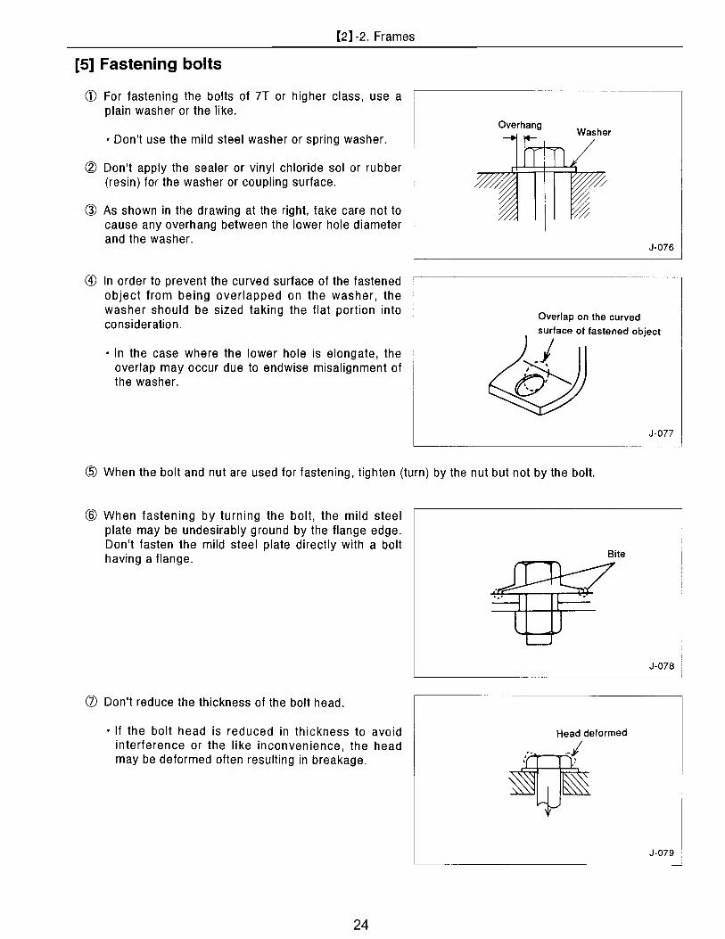
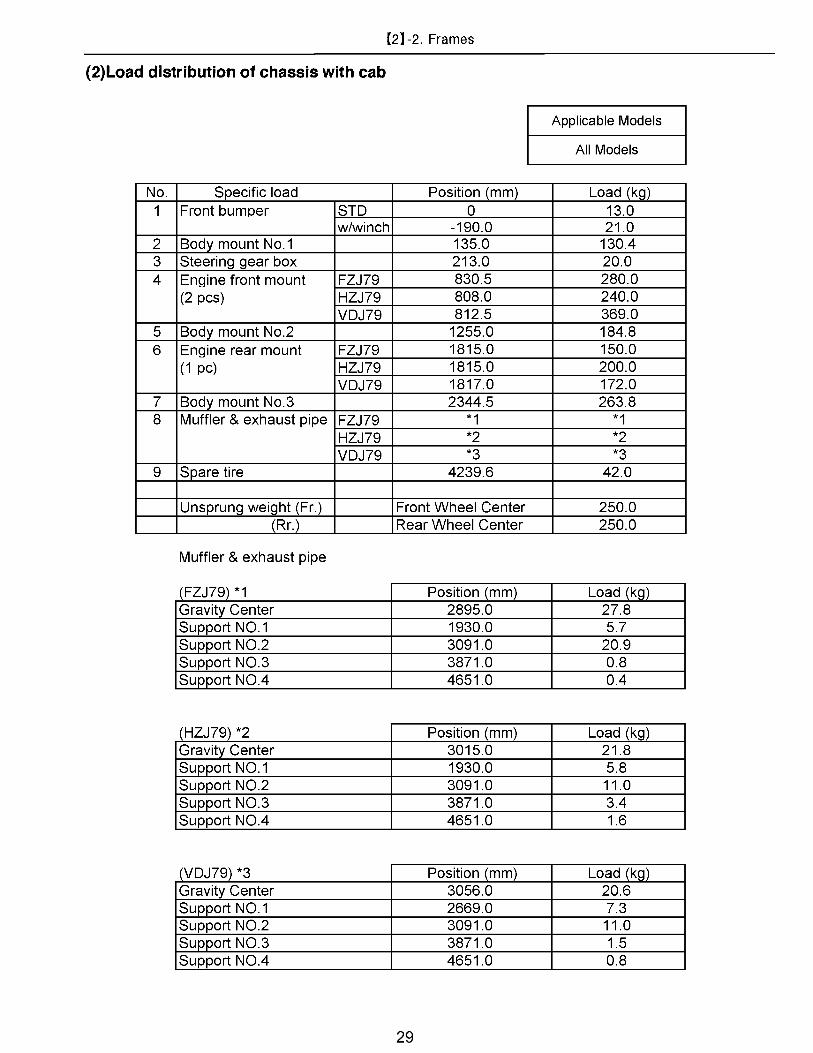
2. Frames............................................................................................................................. 14 [1] Processing ............................................................................................................. 14 [2] Side member reinforcement.................................................................................... 18 [3] Floor joist................................................................................................................ 21 [4] Rear body length and dimensions of longitudinal joist ............................................. 23 [5] Fastening bolts ....................................................................................................... 24 [6] Fixing longitudinal joists .......................................................................................... 25 [7] Data for calculating frame strength.......................................................................... 28
3. Suspension ..................................................................................................................... 30 [1] Front suspension .................................................................................................... 30 [2] Rear suspension..................................................................................................... 30 [3] Tire......................................................................................................................... 30 [4] Bound limit of tire and differential ............................................................................ 30 [5] Data for calculating the ground clearance of frame reference line............................ 31
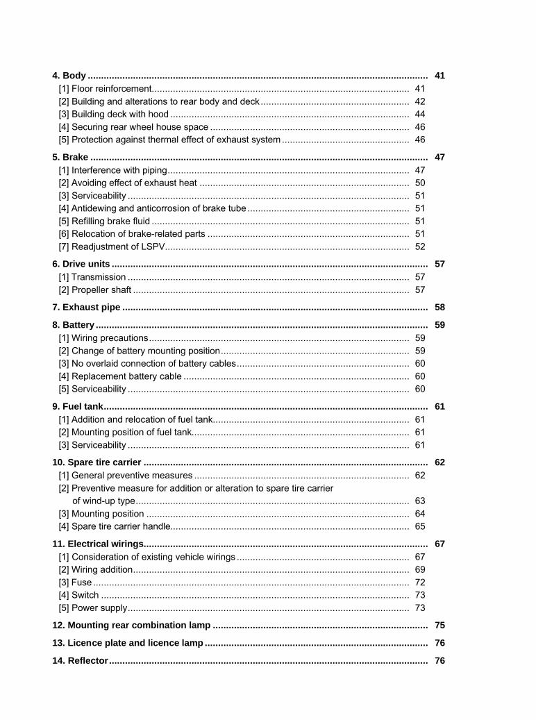
4. Body ................................................................................................................................ 41 [1] Floor reinforcement................................................................................................. 41 [2] Building and alterations to rear body and deck........................................................ 42 [3] Building deck with hood .......................................................................................... 44 [4] Securing rear wheel house space ........................................................................... 46 [5] Protection against thermal effect of exhaust system................................................ 46
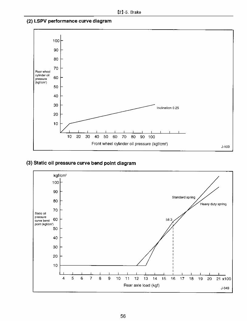
5. Brake ............................................................................................................................... 47 [1] Interference with piping........................................................................................... 47 [2] Avoiding effect of exhaust heat ............................................................................... 50 [3] Serviceability .......................................................................................................... 51 [4] Antidewing and anticorrosion of brake tube............................................................. 51 [5] Refilling brake fluid ................................................................................................. 51 [6] Relocation of brake-related parts ............................................................................ 51 [7] Readjustment of LSPV............................................................................................ 52
6. Drive units ....................................................................................................................... 57 [1] Transmission .......................................................................................................... 57 [2] Propeller shaft ........................................................................................................ 57
7. Exhaust pipe ................................................................................................................... 58
8. Battery ............................................................................................................................. 59 [1] Wiring precautions.................................................................................................. 59 [2] Change of battery mounting position....................................................................... 59 [3] No overlaid connection of battery cables................................................................. 60 [4] Replacement battery cable ..................................................................................... 60 [5] Serviceability .......................................................................................................... 60
9. Fuel tank.......................................................................................................................... 61 [1] Addition and relocation of fuel tank.......................................................................... 61 [2] Mounting position of fuel tank.................................................................................. 61 [3] Serviceability .......................................................................................................... 61
10. Spare tire carrier ........................................................................................................... 62 [1] General preventive measures ................................................................................. 62 [2] Preventive measure for addition or alteration to spare tire carrier of wind-up type....................................................................................................... 63 [3] Mounting position ................................................................................................... 64 [4] Spare tire carrier handle.......................................................................................... 65
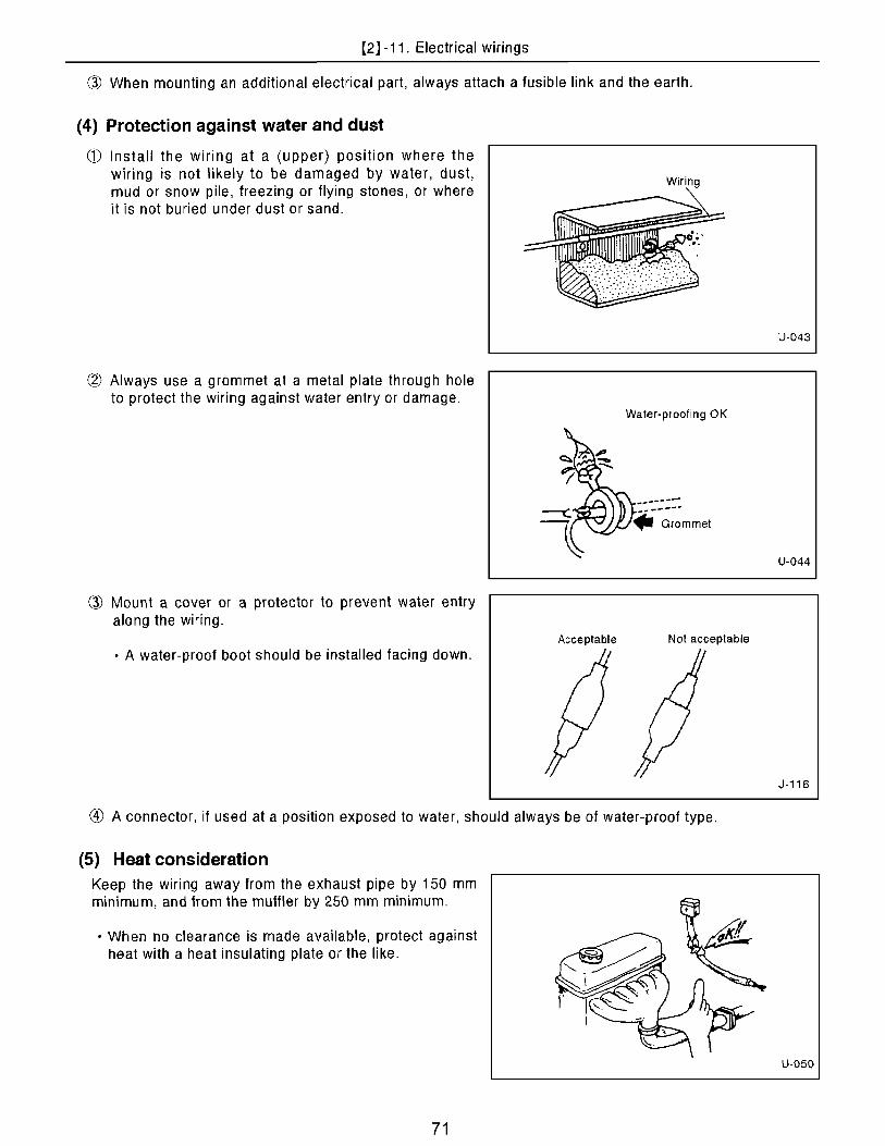
11. Electrical wirings........................................................................................................... 67 [1] Consideration of existing vehicle wirings ................................................................. 67 [2] Wiring addition........................................................................................................ 69 [3] Fuse ....................................................................................................................... 72 [4] Switch .................................................................................................................... 73 [5] Power supply.......................................................................................................... 73
12. Mounting rear combination lamp ................................................................................. 75
13. Licence plate and licence lamp .................................................................................... 76
14. Reflector........................................................................................................................ 76

【3】DRAWINGS ................................................................................................... 77
1. Cab & Chassis drawing .................................................................................................. 77
2. Frame drawing ................................................................................................................ 83
3. Exhaust pipe drawing ..................................................................................................... 85
4. Fuel tank installation-related drawings(Drawings for optional fuel tank)..................... 88
5. Rear combination lamp-related chart............................................................................. 89
6. Licence lamp-related chart ............................................................................................. 90
7. Alternator output characteristic ..................................................................................... 92
(Reference: As for wiring diagram, refer to "Electrical wiring diagram"
published by Technical service division.)
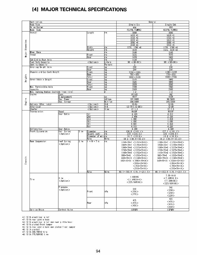
【4】MAJOR TECHNICAL SPECIFICATIONS...................................................... 94

Administrator
1

Administrator
2

Administrator
3

Administrator
4

Administrator
5

Administrator
6

Administrator
7

Administrator
8

Administrator
9

Administrator
10

Administrator
11

Administrator
12

Administrator
13

Administrator
14

Administrator
15

Administrator
16

Administrator
17

Administrator
18

Administrator
19

Administrator
20

Administrator
21

Administrator
22

Administrator
23
Administrator
24

Administrator
25

Administrator
26

Administrator
27

Administrator
28
Administrator
29

Administrator
30

Administrator
31

Administrator
32

Administrator
33

Administrator
34

Administrator
35

Administrator
36

Administrator
37

Administrator
38

Administrator
39

Administrator
40

Administrator
41

Administrator
42

Administrator
43

Administrator
44

Administrator
45

Administrator
46

Administrator
47

Administrator
48

Administrator
49

Administrator
50

Administrator
51

Administrator
52

Administrator
53

Administrator
54

Administrator
55
Administrator
56

Administrator
57

Administrator
58

Administrator
59

Administrator
60

Administrator
61

Administrator
62

Administrator
63

Administrator
64

Administrator
65

Administrator
66

Administrator
67

Administrator
68

Administrator
69

Administrator
70
Administrator
71

Administrator
72

Administrator
73

Administrator
74

Administrator
75

Administrator
76

31-1. Cab & Chassis drawing
77
DRAWINGS MODEL
FZJ79L-TJMRK3
FrameReference Line(H10+30)
*1 w/ schnorkel*2 w/ plated front bumper*3 w/ electrical winch*4 w/ rear pintle hook
2725
2060
1380
3180
5080
1420
1040
*1 1
790
1770
1515
*2 720*3 900
710
1525(TSP)1645(SRP)
*2 5090 *3 5270 *4 5125*2*4 5135 *3*4 5315
1190*4 1235

1-2. Cab & Chassis drawing
78
MODEL
FZJ79L-TJMRK3w/ Fuel Sub Tank
FrameReference Line(H10+30)
*1 w/ schnorkel*2 w/ plated front bumper*3 w/ electrical winch*4 w/ rear pintle hook
625
815
330
1380
2725
20603180
1040
1420
1770
1515
*1 1
790
710*2 720*3 900
1525(TSP)1645(SRP)
5080*2 5090 *3 5270 *4 5125
*2*4 5135 *3*4 5315
1190*4 1235

1-3. Cab & Chassis drawing
79
MODEL
HZJ79L-TJMRS3
FrameReference Line(H10+30)
*1 w/ schnorkel*2 w/ plated front bumper*3 w/ electrical winch*4 w/ rear pintle hook
1420
1040
2725
1380
20603180
1770
*1 1
790
1515
710*2 720*3 900
1525(TSP)1645(SRP)
5080*2 5090 *3 5270 *4 5125
*2*4 5135 *3*4 5315
1190*4 1235

1-4. Cab & Chassis drawing
80
MODEL
HZJ79L-TJMRS3w/ Fuel Sub Tank
FrameReference Line(H10+30)
*1 w/ schnorkel*2 w/ plated front bumper*3 w/ electrical winch*4 w/ rear pintle hook
330
625
815
1420
1040
1380
2725
2060
3180
1770
*1 1
790
1515
710*2 720*3 900
1525(TSP)1645(SRP)
5080*2 5090 *3 5270 *4 5125
*2*4 5135 *3*4 5315
1190*4 1235

1-5. Cab & Chassis drawing
81
MODEL
VDJ79R-TJM*YQ3
FrameReference Line(H10+30)
*1 Tire 265/70R16*2 w/ plated front bumper
1040
2725
1380
2060
3180 1190
1790
*1 1
870
1515
*1 1
555
710*2 720
1525(TSP)1645(SRP)
5080*2 5090
1420
*1 1
460
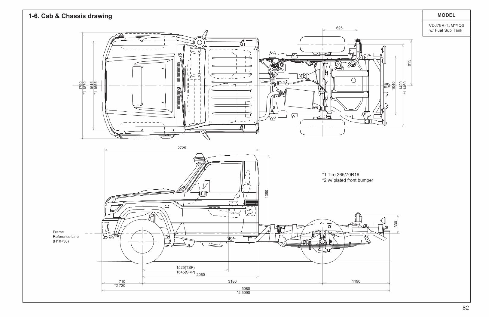
1-6. Cab & Chassis drawing
82
MODEL
VDJ79R-TJM*YQ3w/ Fuel Sub Tank
FrameReference Line(H10+30)
*1 Tire 265/70R16*2 w/ plated front bumper
1040
2725
1380
2060
3180 1190
625
815
330
1790
*1 1
870
1515
*1 1
555
1420
*1 1
460
710*2 720
1525(TSP)1645(SRP)
5080*2 5090

2-1. Frame drawing
83
MODEL
FZJ79L-TJMRK3HZJ79L-TJMRS3
Reference Point dimension
5580
6
6650 520
1046
975.
5
178.5
29.2
757
(Bou
nd S
topp
er)
935.
611
88
600
625
1107
.7
1689
.5
1450
1120
1170
1000
(Spr
ing
Hang
er)
490
120
120
614.8
1000
(Spr
ing
Hang
er)
879
604.8
1025769
490
123
1040
1090
10754880
76
W/Sub TANKW/O Sub TANK
7615
037
0
98182.
1
176.7
120
329.
7
203
76.4
830
3180
21.8
689
195
164
1449
131.
745
164
106.
4
Frame Reference Line (H10+30)
FrontWheelCenter
RearWheelCenter
0
00

2-2. Frame drawing
84
MODEL
VDJ79R-TJMRYQ3VDJ79R-TJMNYQ3
5580
6
1046
6650 520
975.
5
29.2
757
(Bou
nd S
topp
er)
935.
611
88
178.5600
625
1108
.4
1450
1689
.511
20
1170
1000
(Spr
ing
Hang
er)
1000
(Spr
ing
Hang
er)
490
879 12
30
00
490
769
1025
120
120
604.8
614.8
7676
150
370
1040
1090
1075
4880
Reference Point dimension
W/O Sub TANK W/Sub TANK
98182.
1 329.
712
0
176.7
203
76.4
830
3180
21.8
195
164
6891449
4513
1.7
106.
416
4
Frame Reference Line (H10+30)
FrontWheelCenter
RearWheelCenter

FrontWheelCenter
102
143
110
660
630
65
1115
35
RearWheelCenter
Frame Reference Line (H10+30)
3-1. Exhaust pipe drawing
85
MODEL
FZJ79L-TJMRK3

FrontWheelCenter
102
143
110
660
630
1115
35
RearWheelCenter
Frame Reference Line (H10+30)
3-2. Exhaust pipe drawing
86
MODEL
HZJ79L-TJMRS3

FrontWheelCenter
40.1
130
110
660
630
1115
35
RearWheelCenter
Frame Reference Line (H10+30)
3-3. Exhaust pipe drawing
87
MODEL
VDJ79R-TJMRYQ3VDJ79R-TJMNYQ3

4-1. Fuel tank installation-related drawings (Drawings for fuel sub tank)
88
MODEL
All ModelsH10
368.3
220
150
120
120
7676
6485
to Rr Wheel Center 625
Vehicle Center
H10
VDJ, HZJ only
FZJ only
to V
ehic
le C
ente
r 80
5.1

Administrator
89

Administrator
90

Administrator
91

Administrator
92

Administrator
93
Administrator
94

Administrator
95