
1 301 Laboratories Contents - Materials Science and ...msecore.northwestern.edu/301/301labs.pdf ·...
26
1 301 Laboratories Contents 1 301 Laboratories 1 Laboratory 1: Crystal Structure, Imperfections, and Diffraction ................ 2 Objective ............................................ 2 Outcomes ............................................ 2 Exercise 1: Benchtop Simulation of Crystal Structures ................... 2 Exercise 2: Diffraction (HW is the last part below) ..................... 3 Lab Writeup .......................................... 4 Models: Visualizing Defects ................................. 5 DEMO: Atomic Packing illustrated with the “Atomix Raft” ............... 5 DEMO: “Atomic Trampoline” Amorphous vs. Polycrystalline Metal .......... 5 Laboratory 2: Electrical Conductivity & Optoelectronics .................... 6 Prelab .............................................. 6 Exercise 1 ............................................ 6 Exercise 2 ............................................ 7 Lab Writeup .......................................... 8 Laboratory 3: Mechanical Properties of Metals ......................... 10 Objective ............................................ 10 Outcomes ............................................ 10 Experiment ........................................... 10 Homework Problems ..................................... 11 Laboratory 4: Phase Diagrams and Transformations ...................... 13 I. Eutectic salt solidification .................................. 13 II. Steel rod ........................................... 13 III. Shape Memory wires (NiTi) ............................... 14 IV. Bi-Cd binary eutectic alloy ................................ 14 V. Steel wire/carburized steel samples ........................... 14 Homework Problems ..................................... 16 Laboratory 5: Mechanical Behavior of Ceramics and Polymers ................ 17 Polymer 1. Crystallization of Isotatic Polypropylene ................... 17 Ceramics 1. Three-Point bend test (Bonus) ......................... 17 Lab Homework ......................................... 17 Ceramics 2. Softening glass .................................. 18 Polymers 2: Nylon Polymerization ............................. 18 Polymers 3. Plastic Deformation of Polyethylene ..................... 18 Polymers 4. Plastic Deformation of Polyethylene ..................... 19 Polymers 5. Rubber nails (Glass Transition Temperature (a)) ............... 19 Polymers 6. Rubber band (Glass Transition Temperature (b)) .............. 19 Polymers 7. Happy/ Sad balls (Glass Transition Temperature (c)) ............ 19 Ceramics Demonstrations ................................... 20 Addendum: ........................................... 21 Discovery Lab 1: Cholesteryl Ester Liquid Crystals ....................... 22 Pre-lab .............................................. 22 Lab Part 1 ............................................ 23 1
Transcript of 1 301 Laboratories Contents - Materials Science and ...msecore.northwestern.edu/301/301labs.pdf ·...
1 301 Laboratories
Contents
1 301 Laboratories 1Laboratory 1: Crystal Structure, Imperfections, and Diffraction . . . . . . . . . . . . . . . . 2
Objective . . . . . . . . . . . . . . . . . . . . . . . . . . . . . . . . . . . . . . . . . . . . 2Outcomes . . . . . . . . . . . . . . . . . . . . . . . . . . . . . . . . . . . . . . . . . . . . 2Exercise 1: Benchtop Simulation of Crystal Structures . . . . . . . . . . . . . . . . . . . 2Exercise 2: Diffraction (HW is the last part below) . . . . . . . . . . . . . . . . . . . . . 3Lab Writeup . . . . . . . . . . . . . . . . . . . . . . . . . . . . . . . . . . . . . . . . . . 4Models: Visualizing Defects . . . . . . . . . . . . . . . . . . . . . . . . . . . . . . . . . 5DEMO: Atomic Packing illustrated with the “Atomix Raft” . . . . . . . . . . . . . . . 5DEMO: “Atomic Trampoline” Amorphous vs. Polycrystalline Metal . . . . . . . . . . 5
Laboratory 2: Electrical Conductivity & Optoelectronics . . . . . . . . . . . . . . . . . . . . 6Prelab . . . . . . . . . . . . . . . . . . . . . . . . . . . . . . . . . . . . . . . . . . . . . . 6Exercise 1 . . . . . . . . . . . . . . . . . . . . . . . . . . . . . . . . . . . . . . . . . . . . 6Exercise 2 . . . . . . . . . . . . . . . . . . . . . . . . . . . . . . . . . . . . . . . . . . . . 7Lab Writeup . . . . . . . . . . . . . . . . . . . . . . . . . . . . . . . . . . . . . . . . . . 8
Laboratory 3: Mechanical Properties of Metals . . . . . . . . . . . . . . . . . . . . . . . . . 10Objective . . . . . . . . . . . . . . . . . . . . . . . . . . . . . . . . . . . . . . . . . . . . 10Outcomes . . . . . . . . . . . . . . . . . . . . . . . . . . . . . . . . . . . . . . . . . . . . 10Experiment . . . . . . . . . . . . . . . . . . . . . . . . . . . . . . . . . . . . . . . . . . . 10Homework Problems . . . . . . . . . . . . . . . . . . . . . . . . . . . . . . . . . . . . . 11
Laboratory 4: Phase Diagrams and Transformations . . . . . . . . . . . . . . . . . . . . . . 13I. Eutectic salt solidification . . . . . . . . . . . . . . . . . . . . . . . . . . . . . . . . . . 13II. Steel rod . . . . . . . . . . . . . . . . . . . . . . . . . . . . . . . . . . . . . . . . . . . 13III. Shape Memory wires (NiTi) . . . . . . . . . . . . . . . . . . . . . . . . . . . . . . . 14IV. Bi-Cd binary eutectic alloy . . . . . . . . . . . . . . . . . . . . . . . . . . . . . . . . 14V. Steel wire/carburized steel samples . . . . . . . . . . . . . . . . . . . . . . . . . . . 14Homework Problems . . . . . . . . . . . . . . . . . . . . . . . . . . . . . . . . . . . . . 16
Laboratory 5: Mechanical Behavior of Ceramics and Polymers . . . . . . . . . . . . . . . . 17Polymer 1. Crystallization of Isotatic Polypropylene . . . . . . . . . . . . . . . . . . . 17Ceramics 1. Three-Point bend test (Bonus) . . . . . . . . . . . . . . . . . . . . . . . . . 17Lab Homework . . . . . . . . . . . . . . . . . . . . . . . . . . . . . . . . . . . . . . . . . 17Ceramics 2. Softening glass . . . . . . . . . . . . . . . . . . . . . . . . . . . . . . . . . . 18Polymers 2: Nylon Polymerization . . . . . . . . . . . . . . . . . . . . . . . . . . . . . 18Polymers 3. Plastic Deformation of Polyethylene . . . . . . . . . . . . . . . . . . . . . 18Polymers 4. Plastic Deformation of Polyethylene . . . . . . . . . . . . . . . . . . . . . 19Polymers 5. Rubber nails (Glass Transition Temperature (a)) . . . . . . . . . . . . . . . 19Polymers 6. Rubber band (Glass Transition Temperature (b)) . . . . . . . . . . . . . . 19Polymers 7. Happy/ Sad balls (Glass Transition Temperature (c)) . . . . . . . . . . . . 19Ceramics Demonstrations . . . . . . . . . . . . . . . . . . . . . . . . . . . . . . . . . . . 20Addendum: . . . . . . . . . . . . . . . . . . . . . . . . . . . . . . . . . . . . . . . . . . . 21
Discovery Lab 1: Cholesteryl Ester Liquid Crystals . . . . . . . . . . . . . . . . . . . . . . . 22Pre-lab . . . . . . . . . . . . . . . . . . . . . . . . . . . . . . . . . . . . . . . . . . . . . . 22Lab Part 1 . . . . . . . . . . . . . . . . . . . . . . . . . . . . . . . . . . . . . . . . . . . . 23
1
Lab Part 2 . . . . . . . . . . . . . . . . . . . . . . . . . . . . . . . . . . . . . . . . . . . . 25
Laboratory 1: Crystal Structure, Imperfections, and Diffraction
Objective
The objectives of this lab are to gain a better understanding of crystal structures, how they aremeasured and/or identified and the types of defects present in crystalline materials.
Outcomes
Upon completion of the laboratory, the student will be able to:
(a) Distinguish FCC, BCC and HCP structures.(b) Understand how - broadly - diffraction enables qualitative identification and quantitative
measurement of repeating structures.(c) Describe edge and screw dislocations and how they might affect material properties.
Experimental Details Tennis balls simulate “metal atoms” formed into different structures. Alaser pointer, ruler and tape measure are used to measure spacing of a two-dimensional pattern,simulating the application of x-ray diffraction.
Exercise 1: Benchtop Simulation of Crystal Structures
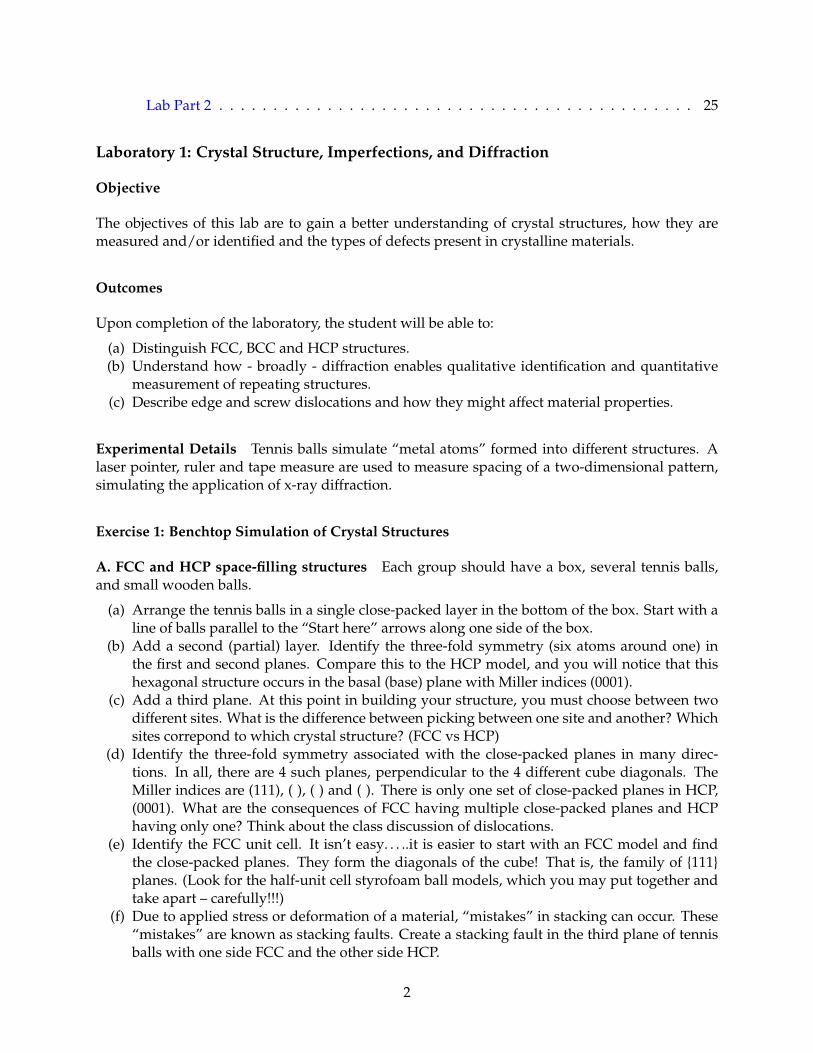
A. FCC and HCP space-filling structures Each group should have a box, several tennis balls,and small wooden balls.
(a) Arrange the tennis balls in a single close-packed layer in the bottom of the box. Start with aline of balls parallel to the “Start here” arrows along one side of the box.
(b) Add a second (partial) layer. Identify the three-fold symmetry (six atoms around one) inthe first and second planes. Compare this to the HCP model, and you will notice that thishexagonal structure occurs in the basal (base) plane with Miller indices (0001).
(c) Add a third plane. At this point in building your structure, you must choose between twodifferent sites. What is the difference between picking between one site and another? Whichsites correpond to which crystal structure? (FCC vs HCP)
(d) Identify the three-fold symmetry associated with the close-packed planes in many direc-tions. In all, there are 4 such planes, perpendicular to the 4 different cube diagonals. TheMiller indices are (111), ( ), ( ) and ( ). There is only one set of close-packed planes in HCP,(0001). What are the consequences of FCC having multiple close-packed planes and HCPhaving only one? Think about the class discussion of dislocations.
(e) Identify the FCC unit cell. It isn’t easy. . . ..it is easier to start with an FCC model and findthe close-packed planes. They form the diagonals of the cube! That is, the family of 111planes. (Look for the half-unit cell styrofoam ball models, which you may put together andtake apart – carefully!!!)
(f) Due to applied stress or deformation of a material, “mistakes” in stacking can occur. These“mistakes” are known as stacking faults. Create a stacking fault in the third plane of tennisballs with one side FCC and the other side HCP.
2
B. Interstitial Sites
(a) You will notice gaps, or interstices, between the spherical atoms. These “interstitial” sitesleave room for small solute atoms, and reinforce that that atomic packing factor (APF) is lessthan 1.
(b) Identify two different interstitial sites: octahedral and tetrahedral. To aid with visualization,you may take the small wooden balls (“solute atoms”) and place them in the intersitial sites.What are the coordination numbers for each of these interstitial sites?
C. Body Centered Cubic Space Filling Model Build a BCC lattice with tennis balls. Be carefulabout which balls touch. How do the interstices of BCC compare to that of the close packedstructures from Part A?
Exercise 2: Diffraction (HW is the last part below)
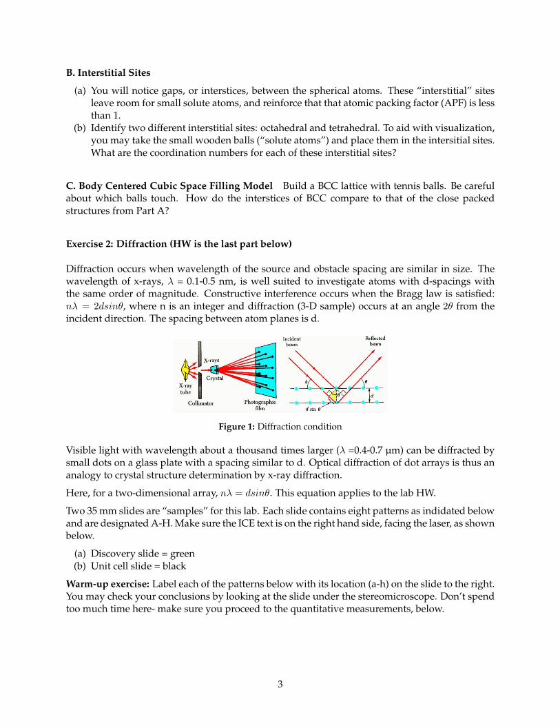
Diffraction occurs when wavelength of the source and obstacle spacing are similar in size. Thewavelength of x-rays, λ = 0.1-0.5 nm, is well suited to investigate atoms with d-spacings withthe same order of magnitude. Constructive interference occurs when the Bragg law is satisfied:nλ = 2dsinθ, where n is an integer and diffraction (3-D sample) occurs at an angle 2θ from theincident direction. The spacing between atom planes is d.
Figure 1: Diffraction condition
Visible light with wavelength about a thousand times larger (λ =0.4-0.7 µm) can be diffracted bysmall dots on a glass plate with a spacing similar to d. Optical diffraction of dot arrays is thus ananalogy to crystal structure determination by x-ray diffraction.
Here, for a two-dimensional array, nλ = dsinθ. This equation applies to the lab HW.
Two 35 mm slides are “samples” for this lab. Each slide contains eight patterns as indidated belowand are designated A-H. Make sure the ICE text is on the right hand side, facing the laser, as shownbelow.
(a) Discovery slide = green(b) Unit cell slide = black
Warm-up exercise: Label each of the patterns below with its location (a-h) on the slide to the right.You may check your conclusions by looking at the slide under the stereomicroscope. Don’t spendtoo much time here- make sure you proceed to the quantitative measurements, below.
3
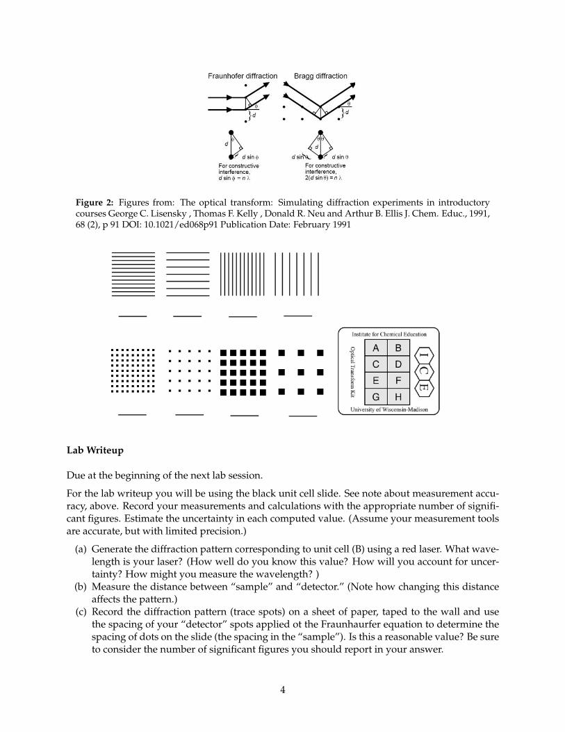
Figure 2: Figures from: The optical transform: Simulating diffraction experiments in introductorycourses George C. Lisensky , Thomas F. Kelly , Donald R. Neu and Arthur B. Ellis J. Chem. Educ., 1991,68 (2), p 91 DOI: 10.1021/ed068p91 Publication Date: February 1991
Lab Writeup
Due at the beginning of the next lab session.
For the lab writeup you will be using the black unit cell slide. See note about measurement accu-racy, above. Record your measurements and calculations with the appropriate number of signifi-cant figures. Estimate the uncertainty in each computed value. (Assume your measurement toolsare accurate, but with limited precision.)
(a) Generate the diffraction pattern corresponding to unit cell (B) using a red laser. What wave-length is your laser? (How well do you know this value? How will you account for uncer-tainty? How might you measure the wavelength? )
(b) Measure the distance between “sample” and “detector.” (Note how changing this distanceaffects the pattern.)
(c) Record the diffraction pattern (trace spots) on a sheet of paper, taped to the wall and usethe spacing of your “detector” spots applied ot the Fraunhaurfer equation to determine thespacing of dots on the slide (the spacing in the “sample”). Is this a reasonable value? Be sureto consider the number of significant figures you should report in your answer.
4
(d) Repeat the process to measure the spading for unit Cell (D) based on the correspondingdiffraction pattern. Again, pay careful attention to the significance of your answer.
(e) What if you used a green laser? Qualitatively, how would the diffraction pattern (displayedon the paper) change?
(f) What type of packing arrangement is observed for Unit Cell (H)?
Models: Visualizing Defects
Look at the models at the front of the room and identify which model represents
(a) an edge dislocation
(b) a screw dislocation
(c) FCC
(d) HCP
(e) BCC
DEMO: Atomic Packing illustrated with the “Atomix Raft”
The steel ball raft is a 2-dimensional model of atomic packing. Observe the following featuresin the demonstration: vacancies, hexagonal-packed grains, square-packed grains, grain and twinboundaries. Similar structures can be seen in (micrographs of) copper and brass samples.
DEMO: “Atomic Trampoline” Amorphous vs. Polycrystalline Metal
The effect of defects and micro-structure on macroscopic properties:
Stacking the tennis balls provides an example of the ordered crystalline arrays that most metalsform. Is it possible for metals to have a completely disordered amorphous structure? Yes. Buttypically these are many-component alloys.
In this demonstration, one base is aluminum (polycrystalline FCC), the second base has a 1/8”thickdisc of amorphous metal alloy (Zr0.42Ti.14Cu.12Ni.10Be.22) glued to the aluminum. As the ballbearing bounces on the aluminum base, it loses kinetic energy to friction, heat and sound gener-ation, and the formation of crystalline defects - slip and dislocation formation. The amorphousmetal plate has a highly disordered structure – it is not a regular crystalline array – and these de-fects do not form. Hence less energy is transferred from the ball to the base. This explains whythese alloys are used in state-of-the-art golf clubs.
5
Laboratory 2: Electrical Conductivity & Optoelectronics
Prelab
Before lab, please READ CAREFULLY both the lab handout and Callister Chapter 18, pages 666-689 & 694-695. The relevant concepts are: Ohm’s Law, the difference between resistance (R) and re-sistivity (ρ), how conductivity changes with temperature in metals vs. semiconductors, bandgaps,and p-n junctions (pp. 694-695). Come in with questions.
Exercise 1
Conductivity and Resistivity In this exercise, we will determine resistance as a function of tem-perature for different materials. This behavior distinguishes semiconductors from metals. If thegeometry of the sample is known, you may convert measured resistance (R) to the correspondingproperty, resistivity (ρ).
A. Metals
(a) Measure the series resistance of your meter and leads: connect the two leads, then turn themeter to the most sensitive resistance scale, which has a maximum value of 200 Ω. (Ignorethe + , which indicates the diode test function.) Note: the meter will read 1 if R is greaterthan the maximum of scale chosen. In that case, turn the dial to the next higher scale.
(b) Measure the resistance R of the steel wire at room temperature. Record R in the table below.(c) Measure R at 77K. With the leads attached, immerse the coil in liquid nitrogen (T = 77 K =
-196 °C). Record the value in the table.(d) Calculate resistivity and conductivity. The wire has a length of 1 meter and a diameter of
0.203 mm. Remember to subtract the series resistance from the measured value of R!(e) Compare your σv to that for "Steel alloy A36" in Table B.9 of the text; some deviation from the
“book value” is expected. Why may your result differ from the book’s?
Temperature R (Ω) ρ(Ωm)
Series resistance RT (~298K)Steel Wire RT
LN2(77K)Graphite Composite RT
LN2(77K)
Table 1: Resistance
Semiconductor: Thermistor
(a) Measure the resistance of the metal oxide thermistor at three or more temperatures between0°C and ~+80°C. Use water baths to expose the thermistor to these temperatures; measurethe water bath temperatures with the thermocouple.
(b) Plot ln(R) vs. 1/T in Kelvin; the slope = Eg/2k. Note that R α 1/σv α exp(Eg/2kT). What isthe effective bandgap, Eg (in eV)? Hint: make sure k is in appropriate units. Typically 0.5 <Eg < 3 eV for semiconductors..
6
Temperature (K)Resistance (Ω)
Table 2: Thermistor Resistance
B. Graphite Composite of Unknown Composite
(a) Measure the resistance of the graphite composite pencil “lead” at room temperature. Recordin the table on pg. 1.
(b) Measure the resistance of the graphite composite cooled in liquid nitrogen. Observe whathappens immediately when it is dunked into the LN2. If the clips freeze, the measurementwill be inaccurate. Record in the table on pg. 1.
(c) Calculate the resistivity of the graphite composite. The diameter of the rod is 0.7 mm. Mea-sure the length between the leads. Does this material behave like a metal or a semiconduc-tor?
Exercise 2
Optoelectronics In this exercise, we will determine the relationship between the current (I)through and voltage across (V) a light emitting diode (LED) and a photoresistor. We will correlatethe I-V behavior with light emission (LED) or absorption (photoresistor).
A. Light Emitting Diode
A light emitting diode is an example of a p-n junction. It is based on a solid solution of GaP andGaAs (GaAsxP1−x). The emission wavelength depends on the composition of this solution, aswell as any dopants present.
(a) Set up the measurement apparatus. Attach the voltmeter clips to the alligator clips on theboard, so it is in parallel with the diode (p-n junction) that you will also attach there. (Note,red = +) Attach the ammeter in series, across the two bare wire connections on the bottom ofthe board. (Connect red to red, so you obtain the correct sign for I.)
(b) Forward Bias (Vbias >0). Do a quick check that as you turn up the voltage (rotate the poston the potentiometer) the diode eventually emits light. Start with the ammeter on the mostsensitive scale (200 μA). Take enough data points (about 10 total) to determine the I-V curvefrom 0V <Vbias <+3V. Remember to note the units for both V,I.
(c) Reverse Bias (Vbias <0) Connect the circuit in reverse bias: take the black lead with the alli-gator clip and attach it to the opposite side of the potentiometer. Again, measure the I- Vresponse. The magnitude should very small; be sure to use the maximum sensitivity of theammeter. Please plot the I-V curve based on both forward and reverse bias on one graph (usegraphing software). Note that the voltage where the current increases rapidly, and where thelight intensity increases, corresponds (approximately) to the bandgap energy. How wouldthe curve change for a green LED? An IR LED?
B. Photoresistor
This photoresistor is made of CdS, a II/VI compound intrinsic semiconductor (not doped). Thebandgap Eg = 2.59 eV, which means that conduction electron/holes provided by thermal energy(kT) are very rare. However, light with energy E(eV) = hc/λ = 1.24/ λ= Eg (λ ≤ 0.48 μm) willpromote valence electrons to create conduction electron/hole pairs. Visible light ranges from 0.4
7

Reverse Bias (-V,-I) Forward Bias (+V,+I)V 0I 0
Light?
Table 3: LED I-V Data
to 0.7 μm. More light will provide more charge carriers (ne = nh), and increasing conductivity σv.A CdS element is the heart of light meters, etc.
(a) Measure R in the dark. Shield the resistor from ambient light with your hand or a cardboardbox. Record the resistance.
(b) Measure R in ambient light. Take photoresistor out of shadow and record the resistance.(c) Observe how R changes with distance from a light source. Move the photoresistor closer to
the ceiling lights. What would happen if you illuminated your photoresistor with monochro-matic 1μm wavelength light?
Dark LightResistance (Ω)
Table 4: Photoresistor resistance
C. Light Emission vs. Composition
Light emission is possible when charge carriers (electrons and holes) recombine across the bandgapof some semiconductors. The four LED’s are solid solutions of GaAs (Eg = 1.4eV) and GaP(Eg=2.3eV).Varying the composition of the solid solution allows us to control the bandgap, and thus vary thecolor of emission.
(a) Observe light emission from the four LEDs. The LEDs have differing ratios of GaAs andGaP- this ratio varies monotonically along the strip. Given what you know, which LED hasthe highest ratio of GaAs:GaP?
(b) Observe the blue LED. This LED is made of a different material. Why might one have toswitch to a different material to get the observed light emission? What property would needto be different?
Lab Writeup
One writeup per person (not per group) is due at the beginning of the next lab session.
Please turn in a full set of data tables, including calculated numbers like resistivity, and answerthe questions/do the tasks in italics. The questions are repeated below for your convenience.
(a) Compare your result for the σv of Steel alloy A36 to that in the book. Why might your valuediffer?
(b) For the Thermistor, Plot ln(R) vs. 1/T in Kelvin; the slope = Eg/2k. Note that R α 1/σv αexp(Eg/2kT).
(c) What is the effective bandgap, Eg (in eV)? Hint: make sure k is in appropriate units. Typi-cally 0.5 < Eg < 3 eV for semiconductors.
(d) Does the graphite composite behave like a metal or a semiconductor?
8
(e) Plot the LED I-V curve based on both forward and reverse bias on one graph (use graphingsoftware).
(f) How would the curve change for a green LED? An IR LED? Note that the voltage wherethe current increases rapidly, and where the light intensity increases, corresponds (approxi-mately) to the bandgap energy.
(g) What would happen if you illuminated your photoresistor with monochromatic 1μm wave-length light?
(h) Given what you know, which LED has the highest ratio of GaAs:GaP?(i) Why might one have to switch to a different material to get the observed light emission?
What property would need to be different?
9
Laboratory 3: Mechanical Properties of Metals
Objective
The objectives of this lab are to explore how crystal structure and defects affect mechanical prop-erties and to understand how these properties are measured.
Outcomes
Upon completion of the laboratory, the student will be able to:
(a) Describe the effects of work-hardening and annealing in metal samples.(b) Describe a ductile-to-brittle transition temperature.(c) Compute the elastic modulus, yield strength, ultimate tensile strength and strain at fracture
from load-displacement (stress-strain) curves.
Experiment
Parts A and B are in Room 2068, while parts C and D are in Room 1034. Safety**
A. Work hardening and annealing in copper - Use caution with torch and hot tubing - seebelow.* You are supplied a length of copper tubing. Grasp it near one end and bend it slightly(through about 20-30). Now bend it back to straighten the piece. You should feel considerableadditional resistance to straightening. Bend and straighten the same place once again, and perhapsa third time. Resistance will continue to grow. Now bend an "original" section near the other end -notice how easy it is to deform the as-received Cu. You are feeling the effect of "work hardening" or"strain hardening". Plastic deformation is accomplished by dislocation motion. The force requiredto achieve plastic deformation also creates many additional dislocations that were not presentinitially.
Dislocations move easily through structurally regular crystals. The dislocations created during thefirst deformation constitute numerous irregularities, and hence make the material more resistantto further deformation, in this case the straightening step. Dislocations are high energy defectsthat can be removed by annealing the material at Ta ~ 0.5Tm. The melting temperature of Cuis 1360 K, so annealing effects are rapid above 680 K or 407 C. The propane torch has a flametemperature greater than 1000 C.
**Keep the propane torch on the table at all times. Holding the Cu tubing with tongs or pliers,heat the "cold worked" region until it is red hot. Cool the entire length of copper and the pliers inwater!! Now test the copper for yield force; you should be back to the original "soft" condition.
B. Rolling of brass As for copper above, brass is capable of significant work hardening. Thepurpose of this exercise is to quantify the effect of work hardening that was observed qualitativelywith the copper tubing. Resistance to yield is here measured by hardness after different extents ofplastic deformation by rolling.
You are provided with a set of brass samples that have been rolled to different thicknesses. Foreach:
10
(a) Measure the thickness of the specimen.(b) Measure its hardness. (Use the Rockwell B scale: 1/16" ball indenter, 100 kg load)
Sample A B C D EThickness
%CWHardness, RB
Table 5: Rolling of brass
C. Charpy impact testing Impact tests (also called Charpy tests) induce fracture under condi-tions of high rates (impact) at an intentional flaw (the notch). This method readily demonstratesthe effect of temperature upon the fracture energy of A36 steel (carbon content of not more than0.30 wt%) and on an Al alloy (2024, 4.4 wt. % Cu). Note: steel is a BCC metal, while Aluminum isFCC. Complete the table below.
Sample Temperature (C) Impact Energy (ft-lb)A36 steel, RT 25CA36 steel, LN -196 C
2024 Al, RT 25 C
2024 Al, LN2 -196 C
Table 6
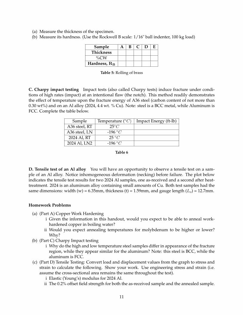
D. Tensile test of an Al alloy You will have an opportunity to observe a tensile test on a sam-ple of an Al alloy. Notice inhomogeneous deformation (necking) before failure. The plot belowindicates the tensile test results for two 2024 Al samples, one as-received and a second after heat-treatment. 2024 is an aluminum alloy containing small amounts of Cu. Both test samples had thesame dimensions: width (w) = 6.35mm, thickness (t) = 1.59mm, and gauge length (Lo) = 12.7mm.
Homework Problems
(a) (Part A) Copper Work Hardeningi Given the information in this handout, would you expect to be able to anneal work-
hardened copper in boiling water?ii Would you expect annealing temperatures for molybdenum to be higher or lower?
Why?(b) (Part C) Charpy Impact testing
i Why do the high and low temperature steel samples differ in appearance of the fractureregion, while they appear similar for the aluminum? Note: this steel is BCC, while thealuminum is FCC.
(c) (Part D) Tensile Testing: Convert load and displacement values from the graph to stress andstrain to calculate the following. Show your work. Use engineering stress and strain (i.e.assume the cross-sectional area remains the same throughout the test).
i Elastic (Young’s) modulus for 2024 Al.ii The 0.2% offset field strength for both the as-received sample and the annealed sample.
11
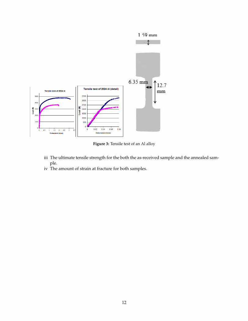
Figure 3: Tensile test of an Al alloy
iii The ultimate tensile strength for the both the as-received sample and the annealed sam-ple.
iv The amount of strain at fracture for both samples.
12
Laboratory 4: Phase Diagrams and Transformations
I. Eutectic salt solidification
Below is part of the phase diagram for the ammonium nitrate-sodium nitrate salt solution. Thediagram shows a eutectic reaction at 21wt% NaNO3.
Figure 4: NH4NO3 −NaNO3
NOTE: Phase diagrams are determined assuming equilibrium and thus predict equilibrium con-centrations and phases. On heating, transitions occur close to equilibrium temperatures. This isnot true for cooling (nucleation).
II. Steel rod
Many useful properties of iron and steel are determined by the crystal structure of the material,which in turn may be altered by heating and cooling. When steel is liquid, carbon dissolves readilyin the iron. Even as a solid, carbon dissolves into the iron, forming a solid solution; however, thesolubility of carbon in iron is limited by the crystal structure, based on the size of the interstitialsites available for carbon in the crystal structure. FCC gamma iron (austenite) can accommodatecarbon at the edges of the crystal cell with little distortion. BCC alpha iron (ferrite) can accom-modate carbon at the edge or face center of a cell; however the sites are smaller, and significantdistortion of the crystal lattice occurs.
When slow cooled, the carbon has time to diffuse through the iron and form cementite Fe3C atdislocation sites; the steel remains ductile at room temperature.
When quenched, the carbon atoms are not given time to diffuse; they force iron atoms out of theusual places in the unit cell, resulting in a distortion of the crystal. This new structure is calledmartensite. It results in material that is hard– because dislocations cannot move easily throughthe distorted lattice, and brittle, for the same reason.
13
If martensite is tempered, that is, heated to a temperature below the eutectoid transformation(usually this means between 250 – 600°C), the material will remain hard, but ductility and tough-ness will be enhanced. (Getting this right with the torch is a bit tricky – because the temperatureis not well-controlled.)
III. Shape Memory wires (NiTi)
The wire on the table is NiTi (or NiTiNOL, named for the NiTi alloys developed at the NavalOrdinance Lab).
(a) Start with the wire at room temperature.(b) Deform it gently, i.e. curl or bend it.(c) Warm it above the austenite transformation temperature, and observe how it recovers.
The low temperature phase (martensite) is deformable, but the alloy “remembers” its shape whenit returns to the higher temperature (austenite) phase at T < 100°C.
IV. Bi-Cd binary eutectic alloy
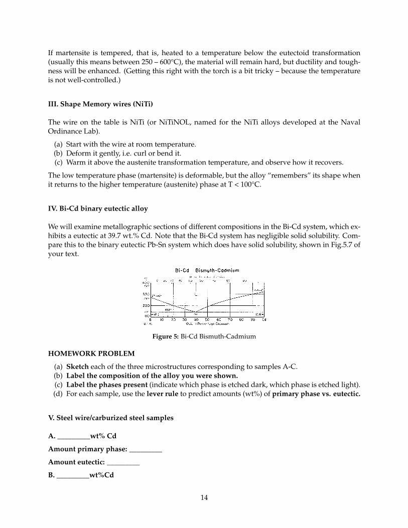
We will examine metallographic sections of different compositions in the Bi-Cd system, which ex-hibits a eutectic at 39.7 wt.% Cd. Note that the Bi-Cd system has negligible solid solubility. Com-pare this to the binary eutectic Pb-Sn system which does have solid solubility, shown in Fig.5.7 ofyour text.
Figure 5: Bi-Cd Bismuth-Cadmium
HOMEWORK PROBLEM
(a) Sketch each of the three microstructures corresponding to samples A-C.(b) Label the composition of the alloy you were shown.(c) Label the phases present (indicate which phase is etched dark, which phase is etched light).(d) For each sample, use the lever rule to predict amounts (wt%) of primary phase vs. eutectic.
V. Steel wire/carburized steel samples
A. _________wt% Cd
Amount primary phase: _________
Amount eutectic: _________
B. _________wt%Cd
14
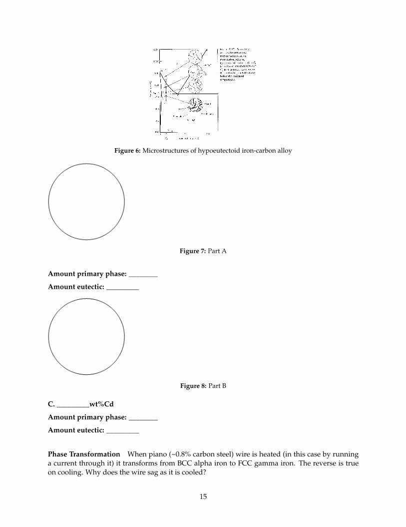
Figure 6: Microstructures of hypoeutectoid iron-carbon alloy
Figure 7: Part A
Amount primary phase: ________
Amount eutectic: _________
Figure 8: Part B
C. _________wt%Cd
Amount primary phase: ________
Amount eutectic: _________
Phase Transformation When piano (~0.8% carbon steel) wire is heated (in this case by runninga current through it) it transforms from BCC alpha iron to FCC gamma iron. The reverse is trueon cooling. Why does the wire sag as it is cooled?
15
Figure 9: Part C
Name: ______________________
Homework Problems
(a) Identify (circle) the eutectic phase transformation on the NH4NO3-NaNO3 phase diagramand indicate the temperature/composition at which it occurs.
(b) Explain why steel quenched from high temperature which forms a martensite phase exhibitshigher hardness and strength then slow cooled steel which forms a mixture of ferrite/cemen-tite.
(c)i Sketch each of the three microstructures you observed, corresponding to samples A-C.
ii Label the composition of the alloy you were shown.iii Label the phases present, which is etched dark and which is etched light?iv For each of the samples use the lever rules to predict the amounts (wt %) of the primary
phase vs. the eutectic.v Are the samples hypo- or hyper eutectic?
4. When piano (~0.8% carbon steel) wire is heated (in this case by running a current through it) ittransforms from BCC alpha iron to FCC gamma iron. The reverse is true on cooling. Why doesthe wire sag as it cools?
16
Laboratory 5: Mechanical Behavior of Ceramics and Polymers
Polymer 1. Crystallization of Isotatic Polypropylene
When cooled from the melt, this isomer, with R = CH3 groups all on the same side of the chain,crystallizes into spherulites. Note that crystallization occurs below Tm = 165 oC (undercooling).
Ceramics 1. Three-Point bend test (Bonus)
It is difficult to perform conventional tensile tests on most ceramic materials; they are brittle andbreak in the grips of the test apparatus. It is easier to test these materials in the bending mode, asillustrated below. Note that when loaded, the top of the material is in compression and the bottomis in tension.
Figure 10: Three-point bend test
A. Measure the force F (weight of volume of water plus container) to fracture a pristine glassmicroscope slide.
B. Abrade a second microscope slide with 180 grit (a = 80 µm) paper. Abrasion should be incenter of slide, and in the "b" direction (above). BE SURE YOUR HANDS AND SLIDE ARE DRY.Measure fracture force for slide with flaw dimension a; flaw on bottom (tensile side).
C. If time permits, repeat part b with abraded side up (under compression). This should be closeto your answer in part a.
D. Glassblowers often use the trick of scribing a mark, then wetting it, to get the glass to breakthere. If you notice the maximum load is less when the abraded region of the slide is wet, youhave observed stress corrosion cracking. The Si-O-Si network in the glass is broken by formationof Si-O-H bonds at the surface, and the material effectively "unzips."
Container weight = 118 g (Add to obtain total load) Vol (ml) Total load (g)A. Pristine slide: vol. (ml)B. Flawed slide: vol. (ml)C. Compression: vol. (ml)
D. Repeat b, but WET abraded region
Table 7: Bend test results
Lab Homework
(a) Calculate fracture force for experiments A and B.(b) Use equation 12.3a in Callister (see addendum) to calculate the "flexural strength" obtained
with this three point bend experiment. Sample dimensions are d = 1 mm, b = 25 mm, andL = 62 mm between support points. Your answer should be in MPa, and you will need toconvert Ff from g to N.
17
(c) Use your result from experiment B and the following equation to calculate KIC for the mi-croscope glass material: KIC = Y σf
√πa , where a is the flaw size (= 80µ) and Y, dependent
on sample & flaw geometry = 1. Compare your KIC to the range predicted for ceramicmaterials in Table 8.1.
(d) Use your KIC and the result from experiment A to calculate flaw size a in the pristine glassslide (the slide you did not intentionally scratch).
Ceramics 2. Softening glass
Hold the glass rod in the flame of the propane torch. When the rod becomes hot enough, that iswhen the temperature exceeds the "glass transition temperature," Tg, the glass will flow and youcan easily bend it. BE CAREFUL NOT TO BURN YOUR FINGERS. Don’t touch the HOT glass.
Polymers 2: Nylon Polymerization
Nylon is formed by the reaction of two liquid monomers, here dissolved in immiscible liquids.These can react with each other, but not with themselves:
0.5 M hexamethylenediamine H2N − (CH2)6 −NH2 in 0.5 M NaOH0.2 M sebacoyl chloride Cl − C − (CH2)− C − Cl in hexane
The reaction occurs in a thin layer at the interface between the two liquids. By slowly pullingthe film in this region, a long, continuous filament can be pulled from the beaker. NOTE THEBYPRODUCT IS HCl – so use gloves.
Polymers 3. Plastic Deformation of Polyethylene
(a) With thumbs separated by about 0.5 cm, stretch the strip with a slow, steady force. Thepolyethylene will yield and deform plastically. Here the sliding of planes of atoms (crys-tals) is accompanied by uncoiling sections of the chain-like polymer molecules (amorphousregions).
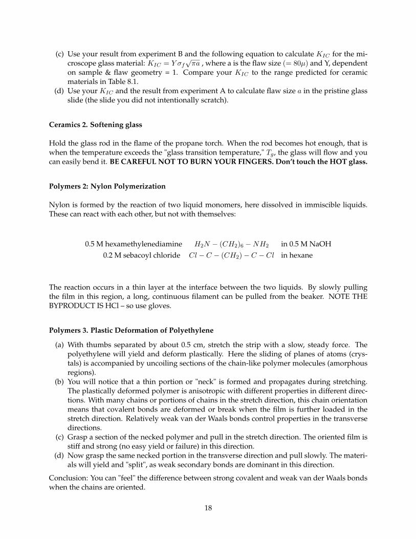
(b) You will notice that a thin portion or "neck" is formed and propagates during stretching.The plastically deformed polymer is anisotropic with different properties in different direc-tions. With many chains or portions of chains in the stretch direction, this chain orientationmeans that covalent bonds are deformed or break when the film is further loaded in thestretch direction. Relatively weak van der Waals bonds control properties in the transversedirections.
(c) Grasp a section of the necked polymer and pull in the stretch direction. The oriented film isstiff and strong (no easy yield or failure) in this direction.
(d) Now grasp the same necked portion in the transverse direction and pull slowly. The materi-als will yield and "split", as weak secondary bonds are dominant in this direction.
Conclusion: You can "feel" the difference between strong covalent and weak van der Waals bondswhen the chains are oriented.
18
Figure 11: Necked polymer
Polymers 4. Plastic Deformation of Polyethylene
You are all familiar with "high density" (fc = 0.7) and "low density" (fc = 0.4) polyethylene. As PEat room temperature is a crystal/rubber combination, the elastic modulus of HDPE is larger. Asthere are more crystals, the yield strength σy of HDPE is larger as well.
• With increased yield strength (more crystallinity) comes reduced ductility.• Somewhat similar to BCC metals, the yield strength of polymers is temperature dependent.
(a) Test with your fingers the two flexure samples. Which is high density polyethylene? Whichis low density polyethylene?
(b) Cool the tensile samples in liquid nitrogen and repeat. A substantial change in ductility (andlikewise an increase in yield stress) will be noticed.
Polymers 5. Rubber nails (Glass Transition Temperature (a))
Cool a rubber “nail” by holding in liquid nitrogen (with tongs!!). The material is now a glass. Usethe glassy nail to join two pieces of (soft) balsa wood. Hints: grasp the nail with the tongs; alignthe nail with the grain of the wood; use repeated soft taps to avoid shattering your “nail.” Haveeveryone in your group contribute a nail.
Polymers 6. Rubber band (Glass Transition Temperature (b))
At room temperature, rubber is above its glass transition temperatures Tg = −70C, but at liquidnitrogen temperature, rubber is below Tg.
A stretched rubber band is cooled with liquid nitrogen. The shape is conserved as the macro-molecules are “frozen in”, and the band is very brittle. As the temperature increases back towardroom temperature and Tg is reached, the band recovers its natural undeformed shape.
Polymers 7. Happy/ Sad balls (Glass Transition Temperature (c))
Two polymer balls of different compositions are provided, along with hot water and LN2. DONOT try to FREEZE the balls completely in LN2. Cool them gently, while moving around in asmall amount of liquid, for 10-20 seconds. Otherwise, the balls will fracture.
(a) Drop both balls onto a table at room temperature. Ball 1 is above its Tg and thus bouncesback elastically (rubber elasticity). Ball 2 is near its Tg and dissipates all the kinetic energywithout bouncing.
(b) Heat Ball 2 and repeat the experiment. The ball is now above its Tg and bounces back elasti-cally (rubber elasticity)
(c) Cool Ball 2 and repeat the experiment. The ball is now below its Tg and bounces elastically(glass elasticity).
19
(d) Cool Ball 1 and repeat the experiment. The ball will be glass elastic below Tg , "dead" nearTg and rubber elastic above Tg . Very cool!
What practical items are made from such rubbery elastomers? Rubber o-rings, used to seal sur-faces – except when they get cold, below Tg, they become stiff and don’t conform – hence resultingin leaks. (The Challenger Disaster was a consequence.)
E. Viscoelasticity (Stain rate dependence) Silly Putty is a polymer above its glass transitiontemperature which is thus viscoelastic at room temp. At high strain rates, it behaves elastically,while at low strain-rates, it is viscous.
Ceramics Demonstrations
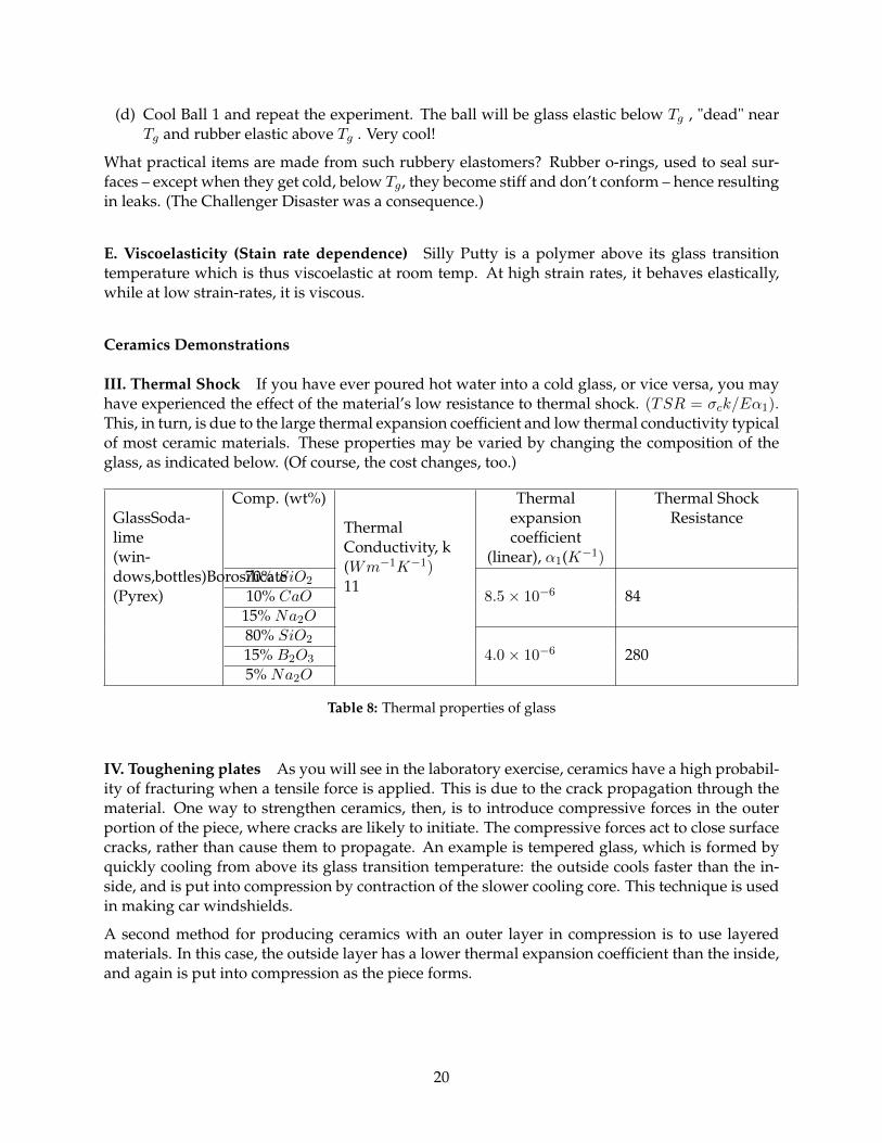
III. Thermal Shock If you have ever poured hot water into a cold glass, or vice versa, you mayhave experienced the effect of the material’s low resistance to thermal shock. (TSR = σck/Eα1).This, in turn, is due to the large thermal expansion coefficient and low thermal conductivity typicalof most ceramic materials. These properties may be varied by changing the composition of theglass, as indicated below. (Of course, the cost changes, too.)
GlassSoda-lime(win-dows,bottles)Borosilicate(Pyrex)
Comp. (wt%)
ThermalConductivity, k(Wm−1K−1)11
Thermalexpansioncoefficient
(linear), α1(K−1)
Thermal ShockResistance
70% SiO2
8.5× 10⁻⁶ 8410% CaO15% Na2O80% SiO2
4.0× 10⁻⁶ 28015% B2O3
5% Na2O
Table 8: Thermal properties of glass
IV. Toughening plates As you will see in the laboratory exercise, ceramics have a high probabil-ity of fracturing when a tensile force is applied. This is due to the crack propagation through thematerial. One way to strengthen ceramics, then, is to introduce compressive forces in the outerportion of the piece, where cracks are likely to initiate. The compressive forces act to close surfacecracks, rather than cause them to propagate. An example is tempered glass, which is formed byquickly cooling from above its glass transition temperature: the outside cools faster than the in-side, and is put into compression by contraction of the slower cooling core. This technique is usedin making car windshields.
A second method for producing ceramics with an outer layer in compression is to use layeredmaterials. In this case, the outside layer has a lower thermal expansion coefficient than the inside,and again is put into compression as the piece forms.
20
V. Tough ceramic ball The material isZr2/CaO “alloy.” At room temperature it contains ~10% ofnonequilibrium tetragonal phase in a matrix of equilibrium monoclinic phase. Large local tensilestress near a crack tip triggers a tet→ mono transition with a 4% volume increase. The largervolume of new monoclinic crystals creates compressive stress that “pinches” the crack shut. KIC
is increased to about 10 MPa m1/2.
VI. Other Ceramics Ceramics are refractrory, That is, they maintain structural integrity at hightemperature, and may provide thermal and electrical insulation. Some are used as capacitors orresistors on computer motherboards. Some are piezoelectric, that is they may be used to transformmechanical energy into a voltage. Others are magnetic (Hard B BaFe12O19, SrFe12O19, used forsmall electric motor field magnets, Refrigerator door seals and posting magnets; Soft B NiFe2O4,MnFe2O4, transformers, inductors) or superconducting.
Addendum:
For a sample with a rectangular cross-section tested on a three-point bend apparatus, the tensilebreaking stress, termed the flexural strength, σfs, is:
σfs =3FbL
2bd2
Here Fb is the load at break, L is the distance between supports, b is the width and d is thethickness of the rectangular cross-section.1
1. Callister, William D. Jr. Materials Science and Engineering: An Introduction, 6th Edition, ISBN 0-471-13576-3, JohnWiley and Sons, Inc., New York, 2003.
21
Discovery Lab 1: Cholesteryl Ester Liquid Crystals
Pre-lab
Important: Be sure that you are wearing long pants and closed -toed shoes for this lab. Lab coats,safety glasses, and gloves will be provided.
Goal To investigate the relationship between temperature, composition, and reflected/trans-mitted colors of a cholesteryl ester liquid crystal.
Background Liquid crystals are organic compounds that are in a state between liquid and solidforms. They are viscous, jelly-like materials that resemble liquids in certain respects (viscosity) andcrystals in other properties (light scattering and reflection). Liquid crystals must be geometricallyhighly anisotropic, as opposed to an isotropic liquid. Such properties, however, can be alteredthrough thermal action (heat) or by the influence of a solvent.
Common liquid crystals are composed of derivatives of cholesterol, C27H46O. Materials thatwill be used in this lab for making the cholesteryl ester liquid crystals are cholesteryl benzoate,C34H50O2, cholesteryl pelargonate, C36H62O2, and cholesteryl oleyl carbonate, C46H80O3.
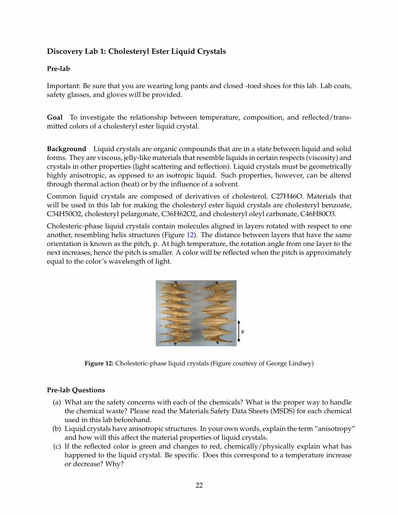
Cholesteric-phase liquid crystals contain molecules aligned in layers rotated with respect to oneanother, resembling helix structures (Figure 12). The distance between layers that have the sameorientation is known as the pitch, p. At high temperature, the rotation angle from one layer to thenext increases, hence the pitch is smaller. A color will be reflected when the pitch is approximatelyequal to the color’s wavelength of light.
Figure 12: Cholesteric-phase liquid crystals (Figure courtesy of George Lindsey)
Pre-lab Questions
(a) What are the safety concerns with each of the chemicals? What is the proper way to handlethe chemical waste? Please read the Materials Safety Data Sheets (MSDS) for each chemicalused in this lab beforehand.
(b) Liquid crystals have anisotropic structures. In your own words, explain the term “anisotropy”and how will this affect the material properties of liquid crystals.
(c) If the reflected color is green and changes to red, chemically/physically explain what hashappened to the liquid crystal. Be specific. Does this correspond to a temperature increaseor decrease? Why?
22
Lab Part 1
Objective Build a cholesteryl ester liquid crystals thermometer that covers the temperature rangebetween 17-40C.
Laboratory Procedure
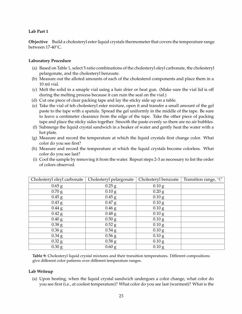
(a) Based on Table 1, select 5 ratio combinations of the cholesteryl oleyl carbonate, the cholesterylpelargonate, and the cholesteryl benzoate.
(b) Measure out the alloted amounts of each of the cholesterol components and place them in a10 ml vial.
(c) Melt the solid in a smaple vial using a hair drier or heat gun. (Make sure the vial lid is offduring the melting process because it can ruin the seal on the vial.)
(d) Cut one piece of clear packing tape and lay the sticky side up on a table.(e) Take the vial of teh cholesteryl ester mixture, open it and transfer a small amount of the gel
paste to the tape with a spatula. Spread the gel uniformly in the middle of the tape. Be sureto leave a centimeter clearance from the edge of the tape. Take the other piece of packingtape and place the sticky sides together. Smooth the paste evenly so there are no air bubbles.
(f) Submerge the liquid crystal sandwich in a beaker of water and gently heat the water with ahot plate.
(g) Measure and record the temperature at which the liquid crystals first change color. Whatcolor do you see first?
(h) Measure and record the temperature at which the liquid crystals become colorless. Whatcolor do you see last?
(i) Cool the sample by removing it from the water. Repeat steps 2-3 as necessary to list the orderof colors observed.
Cholesteryl oleyl carbonate Cholesteryl pelargonate Cholesteryl benzoate Transition range, C0.65 g 0.25 g 0.10 g0.70 g 0.10 g 0.20 g0.45 g 0.45 g 0.10 g0.43 g 0.47 g 0.10 g0.44 g 0.46 g 0.10 g0.42 g 0.48 g 0.10 g0.40 g 0.50 g 0.10 g0.38 g 0.52 g 0.10 g0.36 g 0.54 g 0.10 g0.34 g 0.56 g 0.10 g0.32 g 0.58 g 0.10 g0.30 g 0.60 g 0.10 g
Table 9: Cholesteryl liquid crystal mixtures and their transition temperatures. Different compositionsgive different color patterns over different temperature ranges.
Lab Writeup
(a) Upon heating, when the liquid crystal sandwich undergoes a color change, what color doyou see first (i.e., at coolest temperature)? What color do you see last (warmest)? What is the
23
order of colors you see going from coolest to warmest? Explain what happens to the liquidcrystal during this transition at molecular level.
(b) What is the relationship between the mass of cholesteryl oleyl carbonate in the mixture andthe transition temperature? What do you think might be the reason for this?
(c) As the liquid crystal changes temperature it reflects different colors. Is the color changebetter observed over a black background or a white background? Why?
(d) What are some of the applications you can think of with the temperature sensitive cholesterylester liquid crystals?
(e) What happens if you heat 0.30 g of Cholesteryl oleyl carbonate, Cholesteryl pelargonate,Cholesteryl benzoate by themselves, will you observe the same behavior?
References
(a) Lisensky, G (2007). Preparation of cholesteryl ester liquid crystals. Interdisciplinary Educa-tion Group, Retrieved May 26, 2008.
(b) Lisensky, G, & Boatman, E (2005). Colors in liquid crystals. Journal of Chemical Education,82, 1360A, Retrieved June 4, 2008.
24
Lab Part 2
Liquid crystal display (http://www.microscopyu.com/articles/polarized/polarizedlightintro.html)
One of the most common and practical applications of polarization is the liquid crystal display(LCD) used in numerous devices including wristwatches, computer screens, timers, clocks, and ahost of others. These display systems are based upon the interaction of rod-like liquid crystallinemolecules with an electric field and polarized light waves. The liquid crystalline phase existsin a ground state that is termed cholesteric, in which the molecules are oriented in layers, andeach successive layer is slightly twisted to form a spiral pattern (Figure 13). When polarized lightwaves interact with the liquid crystalline phase the wave is "twisted" by an angle of approximately90 degrees with respect to the incident wave. The exact magnitude of this angle is a function ofthe helical pitch of the cholesteric liquid crystalline phase, which is dependent upon the chemicalcomposition of the molecules (it can be fine-tuned by small changes to the molecular structure).
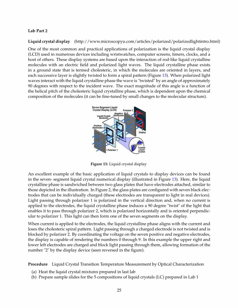
Figure 13: Liquid crystal display
An excellent example of the basic application of liquid crystals to display devices can be foundin the seven- segment liquid crystal numerical display (illustrated in Figure 13). Here, the liquidcrystalline phase is sandwiched between two glass plates that have electrodes attached, similar tothose depicted in the illustration. In Figure 2, the glass plates are configured with seven black elec-trodes that can be individually charged (these electrodes are transparent to light in real devices).Light passing through polarizer 1 is polarized in the vertical direction and, when no current isapplied to the electrodes, the liquid crystalline phase induces a 90 degree "twist" of the light thatenables it to pass through polarizer 2, which is polarized horizontally and is oriented perpendic-ular to polarizer 1. This light can then form one of the seven segments on the display.
When current is applied to the electrodes, the liquid crystalline phase aligns with the current andloses the cholesteric spiral pattern. Light passing through a charged electrode is not twisted and isblocked by polarizer 2. By coordinating the voltage on the seven positive and negative electrodes,the display is capable of rendering the numbers 0 through 9. In this example the upper right andlower left electrodes are charged and block light passing through them, allowing formation of thenumber "2" by the display device (seen reversed in the figure).
Procedure Liquid Crystal Transition Temperature Measurement by Optical Characterization
(a) Heat the liquid crystal mixtures prepared in last lab(b) Prepare sample slides for the 5 compositions of liquid crystals (LC) prepared in Lab 1
25
i It will be helpful if you heat up your slide so that the LC mixture is still liquid whenyou carefully put a coverslip on top of it
ii While placing coverslip try to avoid trapping as many bubble as possible in your sam-ple
(c) TA/instructor will provide instructions on how to operate the optical microscope and recordyour data
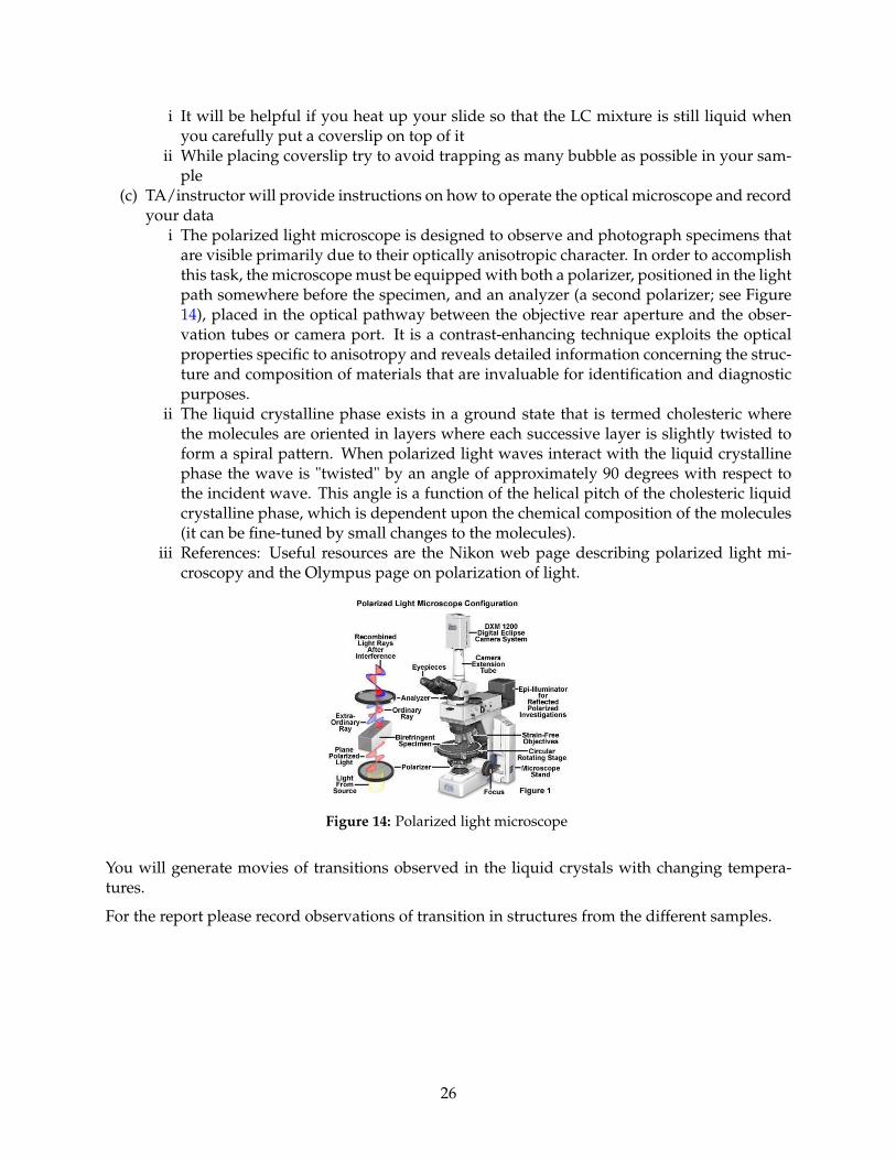
i The polarized light microscope is designed to observe and photograph specimens thatare visible primarily due to their optically anisotropic character. In order to accomplishthis task, the microscope must be equipped with both a polarizer, positioned in the lightpath somewhere before the specimen, and an analyzer (a second polarizer; see Figure14), placed in the optical pathway between the objective rear aperture and the obser-vation tubes or camera port. It is a contrast-enhancing technique exploits the opticalproperties specific to anisotropy and reveals detailed information concerning the struc-ture and composition of materials that are invaluable for identification and diagnosticpurposes.
ii The liquid crystalline phase exists in a ground state that is termed cholesteric wherethe molecules are oriented in layers where each successive layer is slightly twisted toform a spiral pattern. When polarized light waves interact with the liquid crystallinephase the wave is "twisted" by an angle of approximately 90 degrees with respect tothe incident wave. This angle is a function of the helical pitch of the cholesteric liquidcrystalline phase, which is dependent upon the chemical composition of the molecules(it can be fine-tuned by small changes to the molecules).
iii References: Useful resources are the Nikon web page describing polarized light mi-croscopy and the Olympus page on polarization of light.
Figure 14: Polarized light microscope
You will generate movies of transitions observed in the liquid crystals with changing tempera-tures.
For the report please record observations of transition in structures from the different samples.
26


