JIR-301-M manual 1 P.1-4 - Toma JIR-301-M_Manual.pdf · • Specifications of the JIR-301-M and the...
16
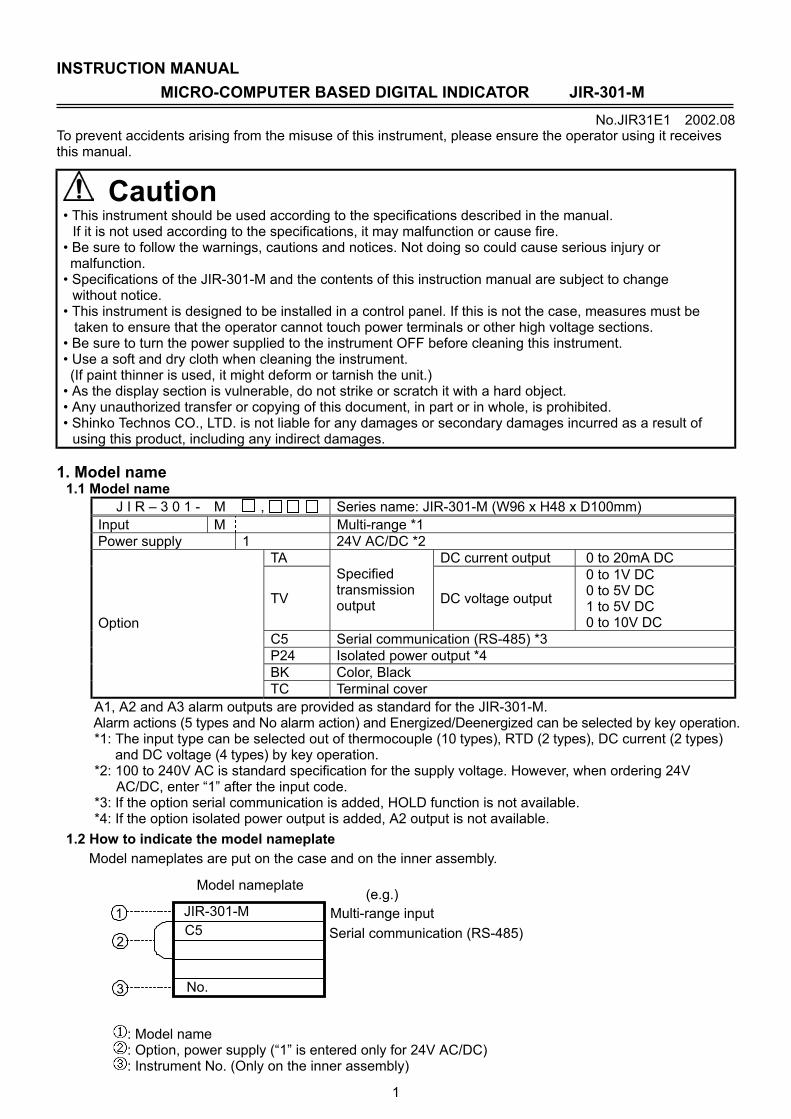
1 INSTRUCTION MANUAL MICRO-COMPUTER BASED DIGITAL INDICATOR JIR-301-M No.JIR31E1 2002.08 To prevent accidents arising from the misuse of this instrument, please ensure the operator using it receives this manual. Caution • This instrument should be used according to the specifications described in the manual. If it is not used according to the specifications, it may malfunction or cause fire. • Be sure to follow the warnings, cautions and notices. Not doing so could cause serious injury or malfunction. • Specifications of the JIR-301-M and the contents of this instruction manual are subject to change without notice. • This instrument is designed to be installed in a control panel. If this is not the case, measures must be taken to ensure that the operator cannot touch power terminals or other high voltage sections. • Be sure to turn the power supplied to the instrument OFF before cleaning this instrument. • Use a soft and dry cloth when cleaning the instrument. (If paint thinner is used, it might deform or tarnish the unit.) • As the display section is vulnerable, do not strike or scratch it with a hard object. • Any unauthorized transfer or copying of this document, in part or in whole, is prohibited. • Shinko Technos CO., LTD. is not liable for any damages or secondary damages incurred as a result of using this product, including any indirect damages. 1. Model name 1.1 Model name J I R – 3 0 1 - M , Series name: JIR-301-M (W96 x H48 x D100mm) Input M Multi-range *1 Power supply 1 24V AC/DC *2 TA DC current output 0 to 20mA DC TV Specified transmission output DC voltage output 0 to 1V DC 0 to 5V DC 1 to 5V DC 0 to 10V DC C5 Serial communication (RS-485) *3 P24 Isolated power output *4 BK Color, Black Option TC Terminal cover A1, A2 and A3 alarm outputs are provided as standard for the JIR-301-M. Alarm actions (5 types and No alarm action) and Energized/Deenergized can be selected by key operation. *1: The input type can be selected out of thermocouple (10 types), RTD (2 types), DC current (2 types) and DC voltage (4 types) by key operation. *2: 100 to 240V AC is standard specification for the supply voltage. However, when ordering 24V AC/DC, enter “1” after the input code. *3: If the option serial communication is added, HOLD function is not available. *4: If the option isolated power output is added, A2 output is not available. 1.2 How to indicate the model nameplate Model nameplates are put on the case and on the inner assembly. : Model name : Option, power supply (“1” is entered only for 24V AC/DC) : Instrument No. (Only on the inner assembly) JIR-301-M C5 No. Model nameplate (e.g.) 3 1 2 Multi-range input Serial communication (RS-485)
Transcript of JIR-301-M manual 1 P.1-4 - Toma JIR-301-M_Manual.pdf · • Specifications of the JIR-301-M and the...
1
INSTRUCTION MANUAL MICRO-COMPUTER BASED DIGITAL INDICATOR JIR-301-M
No.JIR31E1 2002.08 To prevent accidents arising from the misuse of this instrument, please ensure the operator using it receives this manual.
Caution • This instrument should be used according to the specifications described in the manual.
If it is not used according to the specifications, it may malfunction or cause fire. • Be sure to follow the warnings, cautions and notices. Not doing so could cause serious injury or malfunction. • Specifications of the JIR-301-M and the contents of this instruction manual are subject to change
without notice. • This instrument is designed to be installed in a control panel. If this is not the case, measures must be
taken to ensure that the operator cannot touch power terminals or other high voltage sections. • Be sure to turn the power supplied to the instrument OFF before cleaning this instrument. • Use a soft and dry cloth when cleaning the instrument. (If paint thinner is used, it might deform or tarnish the unit.) • As the display section is vulnerable, do not strike or scratch it with a hard object. • Any unauthorized transfer or copying of this document, in part or in whole, is prohibited. • Shinko Technos CO., LTD. is not liable for any damages or secondary damages incurred as a result of
using this product, including any indirect damages. 1. Model name
1.1 Model name J I R – 3 0 1 - M , Series name: JIR-301-M (W96 x H48 x D100mm)
Input M Multi-range *1 Power supply 1 24V AC/DC *2
TA DC current output 0 to 20mA DC
TV
Specified transmission output DC voltage output
0 to 1V DC 0 to 5V DC 1 to 5V DC 0 to 10V DC
C5 Serial communication (RS-485) *3 P24 Isolated power output *4 BK Color, Black
Option
TC Terminal cover A1, A2 and A3 alarm outputs are provided as standard for the JIR-301-M. Alarm actions (5 types and No alarm action) and Energized/Deenergized can be selected by key operation. *1: The input type can be selected out of thermocouple (10 types), RTD (2 types), DC current (2 types)
and DC voltage (4 types) by key operation. *2: 100 to 240V AC is standard specification for the supply voltage. However, when ordering 24V
AC/DC, enter “1” after the input code. *3: If the option serial communication is added, HOLD function is not available. *4: If the option isolated power output is added, A2 output is not available.
1.2 How to indicate the model nameplate Model nameplates are put on the case and on the inner assembly.
: Model name : Option, power supply (“1” is entered only for 24V AC/DC) : Instrument No. (Only on the inner assembly)
JIR-301-MC5
No.
Model nameplate (e.g.)
3
1
2
Multi-range inputSerial communication (RS-485)
2
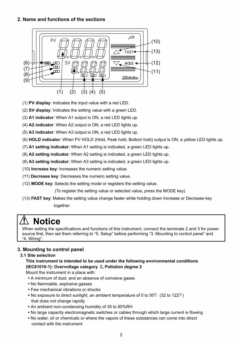
2. Name and functions of the sections
(1) PV display: Indicates the input value with a red LED.
(2) SV display: Indicates the setting value with a green LED. (3) A1 indicator: When A1 output is ON, a red LED lights up.
(4) A2 indicator: When A2 output is ON, a red LED lights up.
(5) A3 indicator: When A3 output is ON, a red LED lights up. (6) HOLD indicator: When PV HOLD (Hold, Peak hold, Bottom hold) output is ON, a yellow LED lights up. (7) A1 setting indicator: When A1 setting is indicated, a green LED lights up.
(8) A2 setting indicator: When A2 setting is indicated, a green LED lights up. (9) A3 setting indicator: When A3 setting is indicated, a green LED lights up.
(10) Increase key: Increases the numeric setting value.
(11) Decrease key: Decreases the numeric setting value.
(12) MODE key: Selects the setting mode or registers the setting value. (To register the setting value or selected value, press the MODE key)
(13) FAST key: Makes the setting value change faster while holding down Increase or Decrease key together.
Notice When setting the specifications and functions of this instrument, connect the terminals 2 and 3 for power source first, then set them referring to “5. Setup” before performing “3. Mounting to control panel” and “4. Wiring”.
3. Mounting to control panel
3.1 Site selection This instrument is intended to be used under the following environmental conditions (IEC61010-1): Overvoltage category , Pollution degree 2
Mount the instrument in a place with: • A minimum of dust, and an absence of corrosive gases • No flammable, explosive gasses
• Few mechanical vibrations or shocks • No exposure to direct sunlight, an ambient temperature of 0 to 50 (32 to 122 )
that does not change rapidly • An ambient non-condensing humidity of 35 to 85%RH • No large capacity electromagnetic switches or cables through which large current is flowing • No water, oil or chemicals or where the vapors of these substances can come into direct
contact with the instrument
(1) (3) (4)(2) (5)
(9)(8)(7)(6)
(11)
(12)
(13)
(10)

3
3.2 External dimension
(Fig. 3.2-1)
3.3 Panel cutout
Lengthwise close mounting n: Number of units mounted
Caution: If lengthwise close mounting is used for the instrument, IP66 specification will not be fulfilled.
(Fig. 3.3-1)
3.4 Mounting Mount the instrument vertically to fulfill the Dust-proof/Drip-proof specification (IP66). Mountable panel thickness: Within 1 to 15mm Insert the instrument from the front side of the panel. Attach the screw type mounting brackets by the holes at the top and bottom of the case and secure the instrument in place with the screws.
(Fig.3.4-1)
Warning As the case is made of resin, do not use excessive force while screwing in the mounting bracket, or the case or screw type mounting bracket could be damaged. The torque is approximately 0.12N•m.
4. Wiring
Warning Turn the power supply to the instrument off before wiring or checking it. Working or touching the terminal with the power switched on may result in Electric Shock causing severe injury or death.
106.2
96
48
11.5104.5 (1)
98.5
Gasket A
44.5
Terminal cover
2 (1
)
130
92 +0.80
92 +0.80
45+0
.5 0
n x
48 -
3+0
.5 0

4
• A1 : Alarm 1 output • A2 : Alarm 2 output • A3 : Alarm 3 output • TRANSMIT OUTPUT: Transmission output • P24 : Isolated power output • HOLD : HOLD function • RS-485 : Serial communication (RS-485) • TC : Thermocouple
• RTD : Resistance temperature detector • DC : DC current, DC voltage
(Fig. 4-1) • Dotted lines show options.
Notice • The terminal block of the JIR-301-M is designed to be wired from the upper side. The lead wire must be inserted from the upper side of the terminal, and fastened by the terminal screw. • Use a thermocouple and compensating lead wire according to the sensor input specification of
this instrument. • Use the 3-wire RTD which corresponds to the input specification of this instrument. • This instrument does not have built-in power switch, circuit breaker or fuse. Therefore, it is
necessary to install them in the circuit near the external instrument. (Recommended fuse: Time-lag fuse, rated voltage 250V AC, rated current 2A)
• When using a 24V AC/DC for the power source, do not confuse the polarity when it is DC. • When using a relay contact output type, externally use a relay according to the capacity of
the load to protect the built-in relay contact. • When wiring, keep input wires (thermocouple, RTD, etc.) away from AC sources or load wires
to avoid external interference. • Do not apply a commercial power source to the sensor connected to the input terminal nor allow the power source to come into contact with the sensor.
Lead wire solderless terminal Use a solderless terminal with isolation sleeve that fits in the M3 screw as shown below. Solderless terminal Manufacturer Model name Tightening
torque Nichifu Terminal Industries CO.,LTD. 1.25Y-3 Y type Japan Solderless Terminal MFG CO.,LTD. VD1.25-B3A Nichifu Terminal Industries CO.,LTD. 1.25-3 Round
type Japan Solderless Terminal MFG CO.,LTD. V1.25-3
0.6N•m Max. 1.0N•m
5. Setup Wire the power terminals only. After the power is turned on, the sensor input characters and temperature unit are indicated on the PV display and the input range high limit value is indicated on the SV display for approx. 3 seconds. (Table 5-1) (If any other value is set in the Scaling high limit setting, the set value is indicated on the SV display) During this time, all outputs and the LED indicators are in OFF status. Indication will then start and the input value will be indicated on the PV display and alarm setting value will be indicated on the SV display. Sensor input PV display SV display PV display SV display K J R S B E T N PL- C (W/Re5-26) Pt100 JPt100
4 to 20mA DC 0 to 20mA DC 0 to 1V DC 0 to 5V DC 1 to 5V DC 0 to 10V DC
Scaling high limit value
Scaling high limit value
����
5.8m
m o
r les
s 3.2mm 3.2mm
����
5.8m
m o
r les
s
(Fig. 4-2)
(Table 5-1)
5
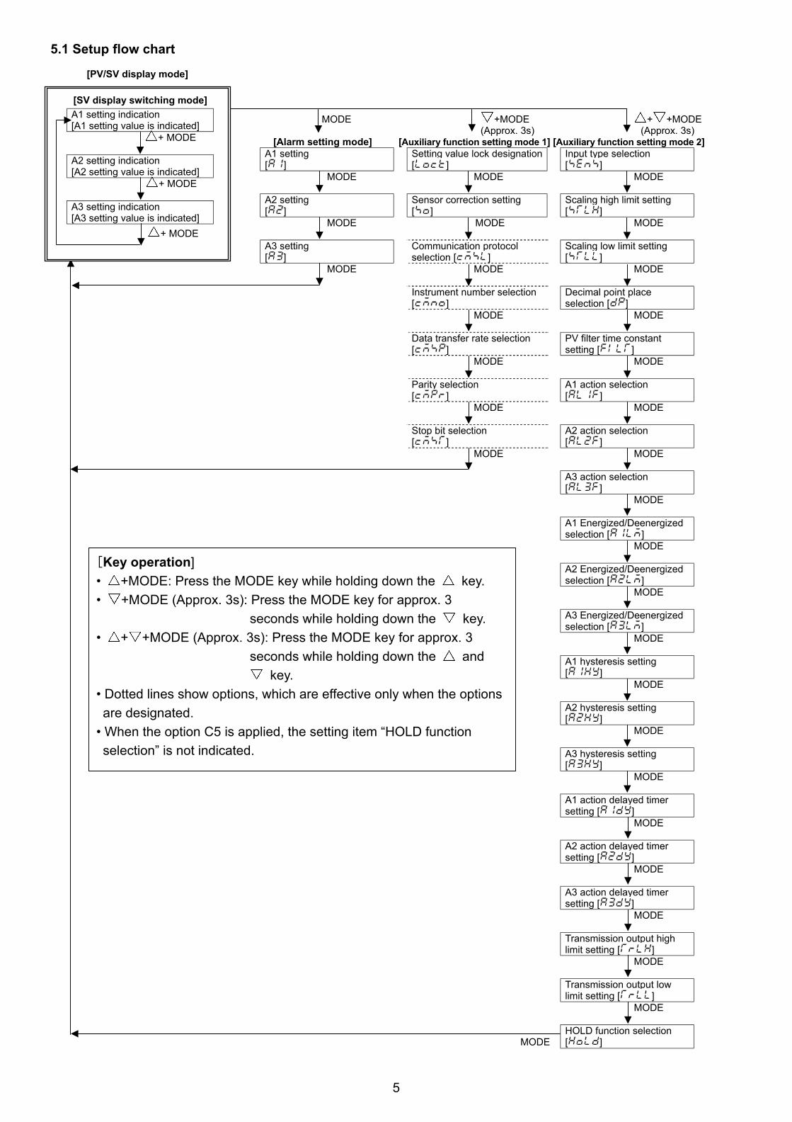
5.1 Setup flow chart
[PV/SV display mode] MODE +MODE + +MODE (Approx. 3s) (Approx. 3s) [Alarm setting mode] [Auxiliary function setting mode 1] [Auxiliary function setting mode 2]
A1 setting [ ]
Setting value lock designation [ ]
Input type selection [ ]
MODE MODE MODE A2 setting [ ]
Sensor correction setting [ ]
Scaling high limit setting [ ]
MODE MODE MODE A3 setting [ ]
Communication protocol selection [ ]
Scaling low limit setting [ ]
MODE MODE MODE
Instrument number selection [ ]
Decimal point place selection [ ]
MODE MODE
Data transfer rate selection [ ]
PV filter time constant setting [ ]
MODE MODE
Parity selection [ ]
A1 action selection [ ]
MODE MODE
Stop bit selection [ ]
A2 action selection [ ]
MODE MODE
A3 action selection [ ]
MODE
A1 Energized/Deenergized selection [ ]
MODE
A2 Energized/Deenergized selection [ ]
MODE
A3 Energized/Deenergized selection [ ]
MODE
A1 hysteresis setting [ ]
MODE
A2 hysteresis setting [ ]
MODE
A3 hysteresis setting [ ]
MODE
A1 action delayed timer setting [ ]
MODE
A2 action delayed timer setting [ ]
MODE
A3 action delayed timer setting [ ]
MODE
Transmission output high limit setting [ ]
MODE
Transmission output low limit setting [ ]
MODE MODE
HOLD function selection [ ]
[Key operation] • +MODE: Press the MODE key while holding down the key. • +MODE (Approx. 3s): Press the MODE key for approx. 3 seconds while holding down the key. • + +MODE (Approx. 3s): Press the MODE key for approx. 3 seconds while holding down the and key. • Dotted lines show options, which are effective only when the options are designated. • When the option C5 is applied, the setting item “HOLD function selection” is not indicated.
[SV display switching mode] A1 setting indication [A1 setting value is indicated] + MODE A2 setting indication [A2 setting value is indicated] + MODE A3 setting indication [A3 setting value is indicated]
+ MODE

6
5.2 Alarm setting mode Character Name, Function, Setting range Default value
A1 setting • Sets A1 output action point. • Not available if No alarm action is selected in A1 action selection. • Refer to (Table 5.2-1).
0
A2 setting • Sets A2 output action point. • Not available if the option Isolated power output is applied, or if No alarm action is selected in A2 action selection. • Refer to (Table 5.2-1).
0
A3 setting • Sets A3 output action point. • Not available if No alarm action or High/Low limit range alarm is selected in A3 action selection. • Refer to (Table 5.2-1).
0
(Table 5.2-1) Alarm action type Setting range
High limit alarm Input range low limit to input range high limit value Low limit alarm Input range low limit to input range high limit value High limit alarm with standby Input range low limit to input range high limit value Low limit alarm with standby Input range low limit to input range high limit value High/Low limit range alarm *1 None
• The placement of the decimal point place follows the selection or input rating. • When input has a decimal point, negative low limit setting value is –199.9, and positive high limit setting value is 999.9. • Setting range of DC current and DC voltage inputs: Scaling low limit to scaling high limit value. *1: High/Low limit range alarm is available only for A3. If High/Low limit range alarm is selected,
the setting items which are related to A3 (A3 setting, A3 action Energized/Deenergized selection, A3 hysteresis setting, A3 action delayed timer setting) will not be indicated.
5.3 SV display switching mode Name, Function Default value
A1 setting value indication • A1 setting value is indicated on the SV display and A1 setting indicator lights up. • Not available if No alarm action is selected in A1 action selection.
0
A2 setting value indication • A2 setting value is indicated on the SV display and A2 setting indicator lights up. • Not available if the option Isolated power output is applied, or if No alarm action is selected in A2 action selection.
0
A3 setting value indication • A3 setting value is indicated on the SV display and A3 setting indicator lights up. • Not available if No alarm action is selected in A3 action selection, or if High/Low
limit range alarm is selected.
0
5.4 Auxiliary function setting mode 1 Character Name, Function, Setting range Default value
Setting value lock designation • Locks the setting values to prevent setting errors. The setting item to be locked depends on the designation.
• (Unlock) : All setting values can be changed. (Lock 1): None of the setting values can be changed. (Lock 2): Only main setting value can be changed. (Lock 3): All setting values can be changed. However, do not change the setting items in the Auxiliary function setting mode 2. They return to their former value after power is turned off because they are not saved in the non-volatile memory.
Unlock
Sensor correction setting • Sets the correction value for the sensor. • Setting range: –100.0 to 100.0 ( ), or –1000 to 1000
0.0
Communication protocol selection • Selects the communication protocol. • Available only when the option Serial communication is applied. • Shinko protocol: , Modbus ASCII mode: ,
Modbus RTU mode:
Shinko protocol

7
Instrument number setting
• Sets the instrument number individually to each instrument when communicating by connecting plural instruments in serial communication.
• Available only when the option Serial communication is added. • Setting range: 0 to 95
0
Data transfer rate selection • Selects a transfer rate to meet the rate of the host computer. • Available only when the option Serial communication is added. • 2400bps: , 4800bps: , 9600bps: , 19200bps:
9600bps
Parity selection • Selects the parity. • Not available when the option Serial communication is not added or when Shinko protocol is selected in the Communication protocol selection. • No parity: , Even parity: ,Odd parity:
Even
Stop bit selection • Selects the stop bit. • Not available when the option Serial communication is not added or when Shinko protocol is selected in the Communication protocol selection. • Setting range: 1, 2
1
5.5 Auxiliary function setting mode 2 Character Name, Function, Setting range Default value
Input type selection • The input type can be selected from thermocouple (10 types), RTD (2 types), DC current (2 types) and DC voltage (4 types),
and the unit / can be selected as well. • When changing the input from DC voltage to other inputs,
remove the sensor connected to this instrument first, then change for the input. If the input is changed with the sensor connected, the input circuit may be broken.
K (–200 to 1370 )
K –200 to 1370 : –199.9 to 400.0 :
J –200 to 1000 : R 0 to 1760 : S 0 to 1760 : B 0 to 1820 : E –200 to 800 : T –199.9 to 400.0 : N –200 to 1300 : PL- 0 to 1390 : C (W/Re5-26) 0 to 2315 : Pt100 –199.9 to 850.0 : JPt100 –199.9 to 500.0 : Pt100 –200 to 850 : JPt100 –200 to 500 : 4 to 20mA DC –1999 to 9999: 0 to 20mA DC –1999 to 9999: 0 to 1V DC –1999 to 9999: 0 to 5V DC –1999 to 9999: 1 to 5V DC –1999 to 9999: 0 to 10V DC –1999 to 9999:
K –320 to 2500 : –199.9 to 750.0 :
J –320 to 1800 : R 0 to 3200 : S 0 to 3200 : B 0 to 3300 : E –320 to 1500 : T –199.9 to 750.0 : N –320 to 2300 : PL- 0 to 2500 : C (W/Re5-26) 0 to 4200 : Pt100 –199.9 to 999.9 : JPt100 –199.9 to 900.0 : Pt100 –300 to 1500 : JPt100 –300 to 900 :
Scaling high limit setting • Sets scaling high limit value. • Available only for DC inputs • Setting range: Scaling low limit value to input range high limit value
9999
Scaling low limit setting • Sets scaling low limit value. • Available only for DC inputs • Setting range: Input range low limit value to scaling high limit value
–1999
Decimal point place selection • Selects decimal point place. • Available only for DC inputs • No decimal point: 2 digits after decimal point:
1 digit after decimal point: 3 digits after decimal point:
No decimal point

8
PV filter time constant setting
• Sets PV filter time constant. (If the value is set too large, it affects alarm action due to the delay of response)
• Setting range: 0.0 to 10.0 seconds
0.0 seconds
A1 action selection • Selects an action for A1. No alarm action :
High limit alarm : High limit alarm with standby: Low limit alarm : Low limit alarm with standby :
No alarm action
A2 action selection • Selects an action for A2. • Not available if the option Isolated power output is added • Action selection and default value are the same as those of A1
action selection.
No alarm action
A3 action selection • Selects an action for A3.
No alarm action: High limit alarm : Low limit alarm : High limit alarm with standby : Low limit alarm with standby : High/Low limit range alarm :
• High/Low limit range alarm is activated depending on A1 and A2 setting values. If both A1 and A2 are turned OFF, A3 is turned ON in combination with A1 High limit alarm (High limit alarm with standby) and A2 Low limit alarm (Low limit alarm with standby) or in combination with A1 Low limit alarm (Low limit alarm with standby) and A2 High limit alarm (High limit alarm with standby).
• If High/Low limit range alarm is selected, A3 related setting items (A3 setting, A3 action Energized/Deenergized selection, A3 hysteresis setting, A3 action delayed timer setting) are not available.)
No alarm action
A1 action Energized/Deenergized selection • Selects Energized/Deenergized for A1. • Not available if No alarm action is selected in A1 action selection • Energized: Deenergized:
Energized
A2 action Energized/Deenergized selection • Selects Energized/Deenergized for A2. • Not available if the option Isolated power output is added or if No alarm action is selected in A2 action selection • Action selection and default value are the same as those of A1 action Energized/Deenergized selection.
Energized
A3 action Energized/Deenergized selection • Selects Energized/Deenergized for A3. • Not available if No alarm action is selected in A3 action selection or if High/Low limit range alarm is selected. • Action selection and default value are the same as those of A1 action Energized/Deenergized selection.
Energized
A1 hysteresis setting • Sets hysteresis for A1. • Not available if No alarm action is selected in A1 action selection • Setting range: 0.1 to 100.0 ( ), or 1 to 1000
1.0
A2 hysteresis setting • Sets hysteresis for A2. • Not available if the option Isolated power output is added or if No alarm action is selected in A2 action selection
• Setting range: 0.1 to 100.0 ( ),or 1 to 1000
1.0
A3 hysteresis setting • Sets hysteresis for A3. • Not available if No alarm action is selected in A3 action selection or if High/Low limit range alarm is selected. • Setting range: 0.1 to 100.0 ( ),or 1 to 1000
1.0
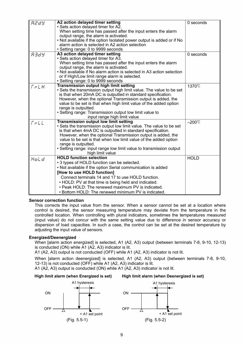
A1 action delayed timer setting • Sets action delayed timer for A1. When setting time has passed after the input enters the alarm output range, the alarm is activated.
• Not available if No alarm action is selected in A1 action selection • Setting range: 0 to 9999 seconds
0 seconds
9
A2 action delayed timer setting • Sets action delayed timer for A2.
When setting time has passed after the input enters the alarm output range, the alarm is activated.
• Not available if the option Isolated power output is added or if No alarm action is selected in A2 action selection
• Setting range: 0 to 9999 seconds
0 seconds
A3 action delayed timer setting • Sets action delayed timer for A3.
When setting time has passed after the input enters the alarm output range, the alarm is activated.
• Not available if No alarm action is selected in A3 action selection or if High/Low limit range alarm is selected. • Setting range: 0 to 9999 seconds
0 seconds
Transmission output high limit setting • Sets the transmission output high limit value. The value to be set is that when 20mA DC is outputted in standard specification. However, when the optional Transmission output is added, the value to be set is that when high limit value of the added option range is outputted. • Setting range: Transmission output low limit value to input range high limit value
1370
Transmission output low limit setting • Sets the transmission output low limit value. The value to be set is that when 4mA DC is outputted in standard specification.
However, when the optional Transmission output is added, the value to be set is that when low limit value of the added option range is outputted.
• Setting range: input range low limit value to transmission output high limit value
–200
HOLD function selection • 3 types of HOLD function can be selected. • Not available if the option Serial communication is added [How to use HOLD function]
Connect terminals 14 and 17 to use HOLD function. • HOLD: PV at that time is being held and indicated. • Peak HOLD: The renewed maximum PV is indicated. • Bottom HOLD: The renewed minimum PV is indicated.
HOLD
Sensor correction function
This corrects the input value from the sensor. When a sensor cannot be set at a location where control is desired, the sensor measuring temperature may deviate from the temperature in the controlled location. When controlling with plural indicators, sometimes the temperatures measured (input value) do not concur with the same setting value due to difference in sensor accuracy or dispersion of load capacities. In such a case, the control can be set at the desired temperature by adjusting the input value of sensors.
Energized/Deenergized When [alarm action energized] is selected, A1 (A2, A3) output (between terminals 7-8, 9-10, 12-13) is conducted (ON) while A1 (A2, A3) indicator is lit. A1 (A2, A3) output is not conducted (OFF) while A1 (A2, A3) indicator is not lit. When [alarm action deenergized] is selected, A1 (A2, A3) output (between terminals 7-8, 9-10, 12-13) is not conducted (OFF) while A1 (A2, A3) indicator is lit. A1 (A2, A3) output is conducted (ON) while A1 (A2, A3) indicator is not lit.
High limit alarm (when Energized is set) High limit alarm (when Deenergized is set) (Fig. 5.5-1) (Fig. 5.5-2)
OFF
ON
A1 hysteresis
+ A1 set pointOFF
ON
+ A1 set point
A1 hysteresis

10
6. Running After the indicator has been mounted to the control panel and wiring is complete, it can be started
in the following manner.
(1) Turn the power supply to the JIR-301-M ON. Turn the power supply to the JIR-301-M ON.
• For approx. 3s after the power is switched ON, the sensor input character and the temperature unit
are indicated on the PV display and input range high limit value is indicated on the SV display. See
(Table 5-1). (If any other value has been set in the Scaling high limit setting, the set value is indicated
on the SV display) During this time, all outputs and LED indicators are in OFF status.
• After that, input value is indicated on the PV display, and alarm setting value is indicated on the SV display.
(2) Input each setting value. Input each setting value, referring to “5. Setup”.
7. Alarm action explanation 7.1 High limit alarm and low limit alarm actions
For A2 output, terminals 9 and 10 are used, and for A3 output, terminals 12 and 13 are used.
A1, A2 and A3 indicators turn on when their output terminals are on, and turn off when their
output terminals are off.
������
����������������������������������������������
: A1 output terminals between 7 and 8 is ON.: A1 output terminals between 7 and 8 is ON or OFF.: A1 output terminals between 7 and 8 is OFF.: Standby functions in this section.
High limit alarm
OFF
ON
Alarm hysteresis
Alarm set pointOFF
ON
Alarm hysteresis
Alarm set point
��������������������������������������������������������������������������������������������������������������������������������������������������������
OFF
ON
Alarm hysteresis
Alarm set point
����������������������������������������������������������������������������������������������������������������������������������������������������
OFF
ON
Alarm hysteresis
Alarm set point
��� ���
������
����
Alarmaction
Alarmaction
outputAlarm
outputAlarm
Low limit alarm
Low limit alarm with standbyHigh limit alarm with standby

11
7.2 High/low limit range alarm action (only for A3)
A3 High/low limit range alarm is activated depending on the status of A1 and A2 indicators (when both A1 and A2 are OFF, A3 is ON). So when using standby function, hysteresis and delayed timer for A1 and A2, be careful about the A3 action point. Note • If A1 or A2 standby function is selected, and while A1 or A2 standby functions, A3 is ON. • When A1 or A2 hysteresis is increased, A3 ON span is decreased. • When A1 or A2 delayed timer setting (time) is increased, A3 ON time is increased. • If A1 or A2 delayed timer setting (time) is set, and while A1 or A2 delayed timer is working
A3 is ON.
: A1 output terminals between 7 and 8 is OFF, A2 output terminals between 9 and 10 is OFF and A3 output terminals between 12 and 13 is ON : A1 output terminals between 7 and 8, A2 output terminals between 9 and 10 and A3 output terminals between 12 and 13 are ON or OFF. : A1 output terminals between 7 and 8 is ON, A2 output terminals between 9 and 10 is ON and A3 output terminals between 12 and 13 is OFF
8. Specifications 8.1 Standard specifications
Mounting method : Flush Setting method : Input system using membrane sheet key Display PV display : Red LED 4 digits, character size 16 x 7.2 mm (H x W)
SV display : Green LED 4 digits, character size 10 x 4.8 mm (H x W) Accuracy (Setting and Indication):
Thermocouple : Within 0.2% of each input span 1digit, or within 2 (4 ), whichever is greater However R, S inputs, 0 to 200 (400 ): Within 6 (12 ) B input, 0 to 300 (600 ): Accuracy is not guaranteed. K, J, E, T, N inputs, less than 0 (32 ): Within 0.4% of each input span 1digit RTD : Within 0.1% of each input span 1digit, or
within 1 (2 ), whichever is greater DC current : Within 0.2% of each input span 1digit DC voltage : Within 0.2% of each input span 1digit
Input sampling period : 0.25 seconds Input Thermocouple : K, J, R, S, B, E, T, N, PL- , C (W/Re5-26) External resistance, 100 or less
(However, B input: External resistance, 40 or less)
������
High/Low limit range alarm action
OFF
ON
A2 (A1) hysteresis
A1 (A2) set point
A1 (A2) hysteresis
A1 (A2) hysteresisset point
A2 (A1) set point
A2 (A1) hysteresisset point
OFF
ON
OFF
ON
����
����
Alarmaction
outputAlarm
[High/Low limit range alarm action]
[Low limit alarm action] [High limit alarm action]
A3 action
12
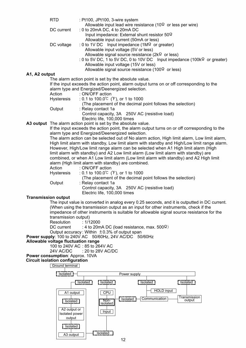
RTD : Pt100, JPt100, 3-wire system Allowable input lead wire resistance (10 or less per wire) DC current : 0 to 20mA DC, 4 to 20mA DC Input impedance: External shunt resistor 50 Allowable input current (50mA or less) DC voltage : 0 to 1V DC Input impedance (1M or greater) Allowable input voltage (5V or less) Allowable signal source resistance (2k or less) : 0 to 5V DC, 1 to 5V DC, 0 to 10V DC Input impedance (100k or greater) Allowable input voltage (15V or less) Allowable signal source resistance (100 or less)
A1, A2 output The alarm action point is set by the absolute value. If the input exceeds the action point, alarm output turns on or off corresponding to the alarm type and Energized/Deenergized selection.
Action : ON/OFF action Hysteresis : 0.1 to 100.0 ( ), or 1 to 1000 (The placement of the decimal point follows the selection)
Output : Relay contact 1a Control capacity, 3A 250V AC (resistive load) Electric life, 100,000 times
A3 output The alarm action point is set by the absolute value. If the input exceeds the action point, the alarm output turns on or off corresponding to the alarm type and Energized/Deenergized selection. The alarm action can be selected out of No alarm action, High limit alarm, Low limit alarm, High limit alarm with standby, Low limit alarm with standby and High/Low limit range alarm. However, High/Low limit range alarm can be selected when A1 High limit alarm (High limit alarm with standby) and A2 Low limit alarm (Low limit alarm with standby) are combined, or when A1 Low limit alarm (Low limit alarm with standby) and A2 High limit alarm (High limit alarm with standby) are combined.
Action : ON/OFF action Hysteresis : 0.1 to 100.0 ( ), or 1 to 1000 (The placement of the decimal point follows the selection)
Output : Relay contact 1a Control capacity, 3A 250V AC (resistive load) Electric life, 100,000 times
Transmission output The input value is converted in analog every 0.25 seconds, and it is outputted in DC current. (When using the transmission output as an input for other instruments, check if the impedance of other instruments is suitable for allowable signal source resistance for the transmission output) Resolution : 1/12000
DC current : 4 to 20mA DC (load resistance, max. 500 ) Output accuracy : Within 0.3% of output span
Power supply: 100 to 240V AC 50/60Hz, 24V AC/DC 50/60Hz Allowable voltage fluctuation range
100 to 240V AC : 85 to 264V AC 24V AC/DC : 20 to 28V AC/DC Power consumption: Approx. 10VA Circuit isolation configuration
Power supply
Isolated Isolated IsolatedIsolated
Isolated
Isolated
Input
CPU
Isolated
Isolated
A3 output
HOLD inputA1 output
A2 output orIsolated power
output
TransmissionoutputCommunicationNon-
isolated
Ground terminal
Isolated
13
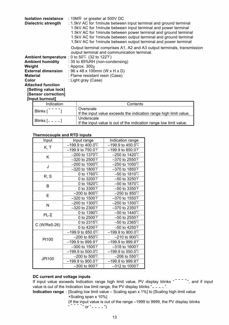
Isolation resistance : 10M or greater at 500V DC Dielectric strength : 1.5kV AC for 1minute between input terminal and ground terminal
1.5kV AC for 1minute between input terminal and power terminal 1.5kV AC for 1minute between power terminal and ground terminal 1.5kV AC for 1minute between output terminal and ground terminal 1.5kV AC for 1minute between output terminal and power terminal Output terminal comprises A1, A2 and A3 output terminals, transmission output terminal and communication terminal.
Ambient temperature : 0 to 50 (32 to 122 ) Ambient humidity : 35 to 85%RH (non-condensing) Weight : Approx. 300g External dimension : 96 x 48 x 100mm (W x H x D) Material : Flame resistant resin (Case) Color : Light gray (Case) Attached function
[Setting value lock] [Sensor correction] [Input burnout]
Indication Contents
Blinks [ ] Overscale If the input value exceeds the indication range high limit value.
Blinks [ ] Underscale If the input value is out of the indication range low limit value.
Thermocouple and RTD inputs Input Input range Indication range
–199.9 to 400.0 –199.9 to 450.0 K, T –199.9 to 750.0 –199.9 to 850.0 –200 to 1370 –250 to 1420 K –320 to 2500 –370 to 2550 –200 to 1000 –250 to 1050 J –320 to 1800 –370 to 1850 0 to 1760 –50 to 1810 R, S 0 to 3200 –50 to 3250 0 to 1820 –50 to 1870 B 0 to 3300 –50 to 3350 –200 to 800 –250 to 850 E –320 to 1500 –370 to 1550 –200 to 1300 –250 to 1350 N –320 to 2300 –370 to 2350 0 to 1390 –50 to 1440 PL- 0 to 2500 –50 to 2550 0 to 2315 –50 to 2365 C (W/Re5-26) 0 to 4200 –50 to 4250
–199.9 to 850.0 –199.9 to 900.0 –200 to 850 –210 to 900
–199.9 to 999.9 –199.9 to 999.9 Pt100
–300 to 1500 –318 to 1600 –199.9 to 500.0 –199.9 to 550.0 –200 to 500 –206 to 550 –199.9 to 900.0 –199.9 to 999.9 JPt100
–300 to 900 –312 to 1000 DC current and voltage inputs If input value exceeds Indication range high limit value, PV display blinks “ ”, and if input value is out of the Indication low limit range, the PV display blinks “ ”. Indication range : [Scaling low limit value – Scaling span x 1%] to [Scaling high limit value +Scaling span x 10%] (If the input value is out of the range –1999 to 9999, the PV display blinks “ ” or “ ”)
14
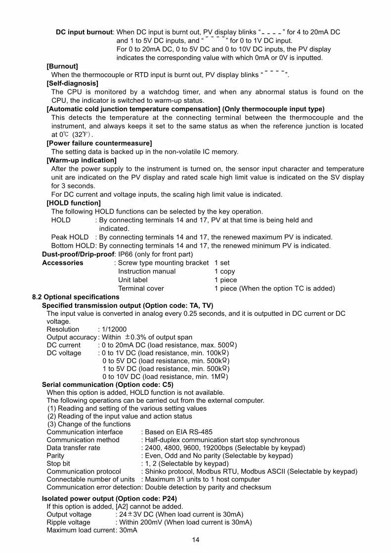
DC input burnout: When DC input is burnt out, PV display blinks “ ” for 4 to 20mA DC and 1 to 5V DC inputs, and “ ” for 0 to 1V DC input.
For 0 to 20mA DC, 0 to 5V DC and 0 to 10V DC inputs, the PV display indicates the corresponding value with which 0mA or 0V is inputted.
[Burnout] When the thermocouple or RTD input is burnt out, PV display blinks “ ”.
[Self-diagnosis] The CPU is monitored by a watchdog timer, and when any abnormal status is found on the CPU, the indicator is switched to warm-up status.
[Automatic cold junction temperature compensation] (Only thermocouple input type) This detects the temperature at the connecting terminal between the thermocouple and the instrument, and always keeps it set to the same status as when the reference junction is located at 0 (32 ).
[Power failure countermeasure] The setting data is backed up in the non-volatile IC memory.
[Warm-up indication] After the power supply to the instrument is turned on, the sensor input character and temperature unit are indicated on the PV display and rated scale high limit value is indicated on the SV display for 3 seconds. For DC current and voltage inputs, the scaling high limit value is indicated.
[HOLD function] The following HOLD functions can be selected by the key operation. HOLD : By connecting terminals 14 and 17, PV at that time is being held and
indicated. Peak HOLD : By connecting terminals 14 and 17, the renewed maximum PV is indicated. Bottom HOLD : By connecting terminals 14 and 17, the renewed minimum PV is indicated.
Dust-proof/Drip-proof: IP66 (only for front part) Accessories : Screw type mounting bracket 1 set Instruction manual 1 copy Unit label 1 piece Terminal cover 1 piece (When the option TC is added)
8.2 Optional specifications Specified transmission output (Option code: TA, TV)
The input value is converted in analog every 0.25 seconds, and it is outputted in DC current or DC voltage. Resolution : 1/12000 Output accuracy : Within 0.3% of output span DC current : 0 to 20mA DC (load resistance, max. 500 ) DC voltage : 0 to 1V DC (load resistance, min. 100k )
0 to 5V DC (load resistance, min. 500k ) 1 to 5V DC (load resistance, min. 500k ) 0 to 10V DC (load resistance, min. 1M )
Serial communication (Option code: C5) When this option is added, HOLD function is not available. The following operations can be carried out from the external computer.
(1) Reading and setting of the various setting values (2) Reading of the input value and action status (3) Change of the functions Communication interface : Based on EIA RS-485 Communication method : Half-duplex communication start stop synchronous Data transfer rate : 2400, 4800, 9600, 19200bps (Selectable by keypad) Parity : Even, Odd and No parity (Selectable by keypad) Stop bit : 1, 2 (Selectable by keypad) Communication protocol : Shinko protocol, Modbus RTU, Modbus ASCII (Selectable by keypad) Connectable number of units : Maximum 31 units to 1 host computer Communication error detection : Double detection by parity and checksum
Isolated power output (Option code: P24) If this option is added, [A2] cannot be added. Output voltage : 24 3V DC (When load current is 30mA) Ripple voltage : Within 200mV (When load current is 30mA) Maximum load current : 30mA

15
Color Black (Option code: BK) Front panel frame and case: Black
Terminal cover (Option code: TC) Electrical shock protecting terminal cover
9. Troubleshooting
If any malfunctions occur, refer to the following items after checking the power supply to the indicator.
Problem Presumed cause and solution [ ] is blinking on the PV display.
• Thermocouple, RTD or DC voltage (0 to 1V DC) input sensor is burnt out. Change each sensor. How to check sensor burnout [Thermocouple]
If the input terminal of the instrument is shorted, and if nearby room temperature is indicated, the instrument should be normal and sensor may be burnt out.
[RTD] If approx. 100 of resistance is connected to the input terminals between A-B of the instrument and between B-B is shorted, then if nearby 0 (32 ) is indicated, the instrument should be normal and sensor may be burnt out. [DC voltage (0 to 1V DC)]
If the input terminal of the instrument is shorted, and if scaling low limit value is indicated, the instrument should be normal and the signal wire may be disconnected.
• Is the input terminal of thermocouple, RTD or DC voltage (0 to 1V DC) securely mounted to the instrument input terminal?
Connect the sensor terminals to the instrument input terminals securely. [ ] is blinking on the PV display.
• Check if input signal source for DC voltage (1 to 5V DC) or DC current (4 to 20mA DC) is normal.
How to check each signal wire [DC voltage (1 to 5V DC)]
If the input to the input terminals of the instrument is 1V DC and scaling low limit value is indicated, the instrument should be normal and the signal wire may be disconnected.
[DC current (4 to 20mA DC)] If the input to the input terminals of the instrument is 4mA DC and scaling low limit value is indicated, the instrument should be normal and the signal wire may be disconnected.
• Is input signal wire for DC voltage (1 to 5V DC) or DC current (4 to 20mA DC) securely connected to the instrument input terminals? Connect the signal lead wire to the instrument input terminals securely.
• Is polarity of thermocouple or compensating lead wire correct? Do codes (A, B, B) of RTD agree with the instrument terminals? Wire them properly.
The PV display keeps indicating the value which was set in the Scaling low limit setting.
• Check if the input signal source for DC voltage (0 to 5V DC, 0 to 10V DC) and DC current (0 to 20mA DC) is normal. How to check each signal wire [DC voltage (0 to 5V DC, 0 to 10V DC)]
If the input to the input terminals of the instrument is 1V DC and the value corresponding to 1V DC is indicated, the instrument should be normal and the signal wire may be disconnected.
[DC current (0 to 20mA DC)] If the input to the input terminals of the instrument is 1mA DC and the value corresponding to 1mA DC is indicated, the instrument should be normal and the signal wire may be disconnected.
• Are the input lead wire terminals for DC voltage (0 to 5V DC, 0 to 10V DC) or DC current (0 to 20mA DC) securely mounted to the instrument input terminals? Mount the sensor terminals to the instrument input terminals securely.

16
The indication of PV display is abnormal or unstable.
• Is sensor input or temperature unit ( or ) correct? Select the proper sensor input and temperature unit ( or ).
• Sensor correcting value is unsuitable. Set the value suitably.
• Is the specification of the sensor correct? Set the sensor to the proper specification. • AC leaks into the sensor circuit.
Use an ungrounded type sensor. • There may be a piece of equipment producing inductive
interference or noise near the indicator. Keep the equipment producing inductive interference or noise away from the indicator.
The PV display is indicating [ ].
• Internal memory is defective. Contact our agency or us.
The value on the PV display does not change.
• Is HOLD function working? Release the HOLD function.
The values do not change by or key.
• Setting value lock (Lock 1 or Lock 2) is designated. Release the lock designation.
• If you have any inquiries, please consult our agency or the shop where you purchased the unit.
SHINKO NORTH AMERICA
:
::
Office
URLE-mail
25 Whitefriars DriveToronto, Ontario M3A 2L7 http://[email protected]
Tel :Fax:
416 444-0817416 444-2361