05 Pumps
60
Chapter 5: Pumps Rules of Thumb for Chemical Engineers, 5th Edition by Stephen Hall This Excel workbook includes Visual Basic for Application function subroutines. Macros must be enabled for them to work.
-
Upload
roberto-oconnor -
Category
Documents
-
view
154 -
download
5
Transcript of 05 Pumps
Chapter 5: PumpsRules of Thumb for Chemical Engineers, 5th Edition
by Stephen Hall
This Excel workbook includes Visual Basic for Application function subroutines.Macros must be enabled for them to work.

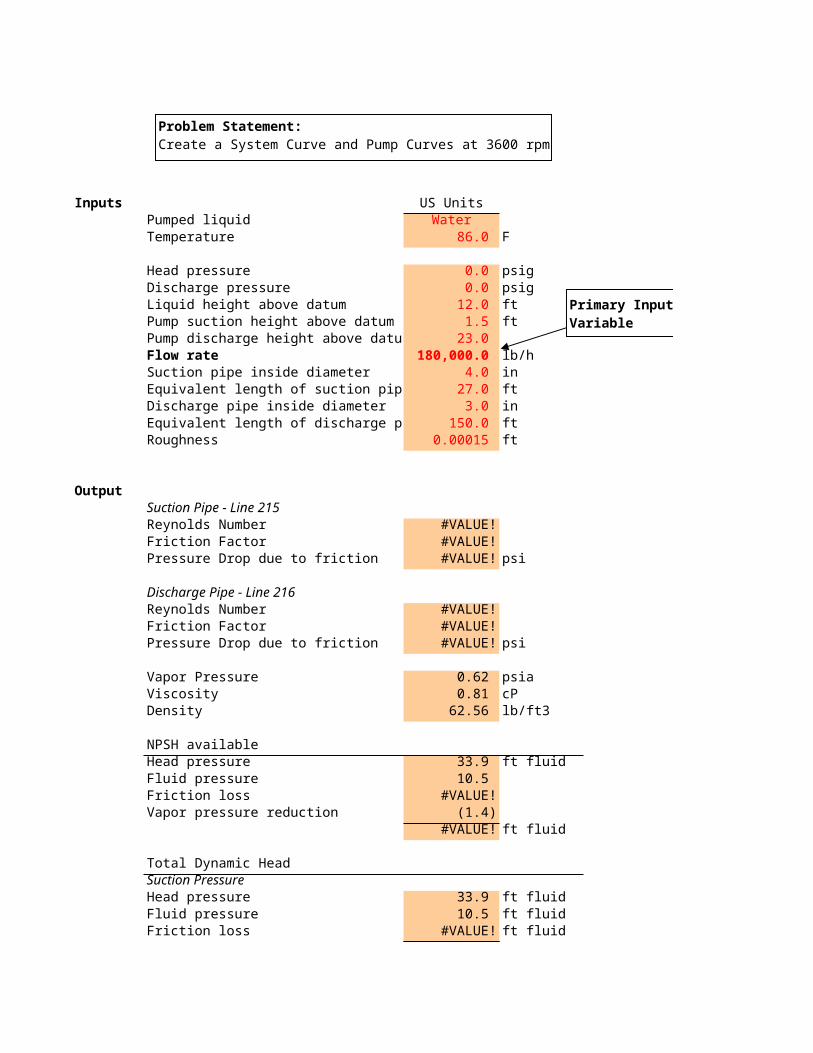
Inputs US UnitsPumped liquid WaterTemperature 86.0 F
Head pressure 0.0 psigDischarge pressure 0.0 psigLiquid height above datum 12.0 ftPump suction height above datum 1.5 ftPump discharge height above datum 23.0 Flow rate 180,000.0 lb/hSuction pipe inside diameter 4.0 inEquivalent length of suction pipe 27.0 ftDischarge pipe inside diameter 3.0 inEquivalent length of discharge pipe 150.0 ftRoughness 0.00015 ft
OutputSuction Pipe - Line 215Reynolds Number #VALUE!Friction Factor #VALUE!Pressure Drop due to friction #VALUE! psi
Discharge Pipe - Line 216Reynolds Number #VALUE!Friction Factor #VALUE!Pressure Drop due to friction #VALUE! psi
Vapor Pressure 0.62 psiaViscosity 0.81 cPDensity 62.56 lb/ft3
NPSH availableHead pressure 33.9 ft fluidFluid pressure 10.5 Friction loss #VALUE!Vapor pressure reduction (1.4)
#VALUE! ft fluid
Total Dynamic HeadSuction PressureHead pressure 33.9 ft fluidFluid pressure 10.5 ft fluidFriction loss #VALUE! ft fluid
Problem Statement:Create a System Curve and Pump Curves at 3600 rpm
Primary Input Variable

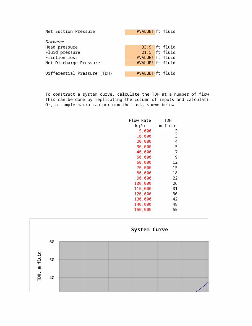
Net Suction Pressure #VALUE! ft fluid
DischargeHead pressure 33.9 ft fluidFluid pressure 21.5 ft fluidFriction loss #VALUE! ft fluidNet Discharge Pressure #VALUE! ft fluid
Differential Pressure (TDH) #VALUE! ft fluid
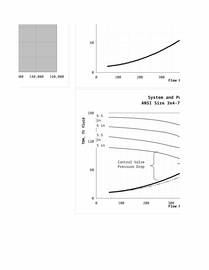
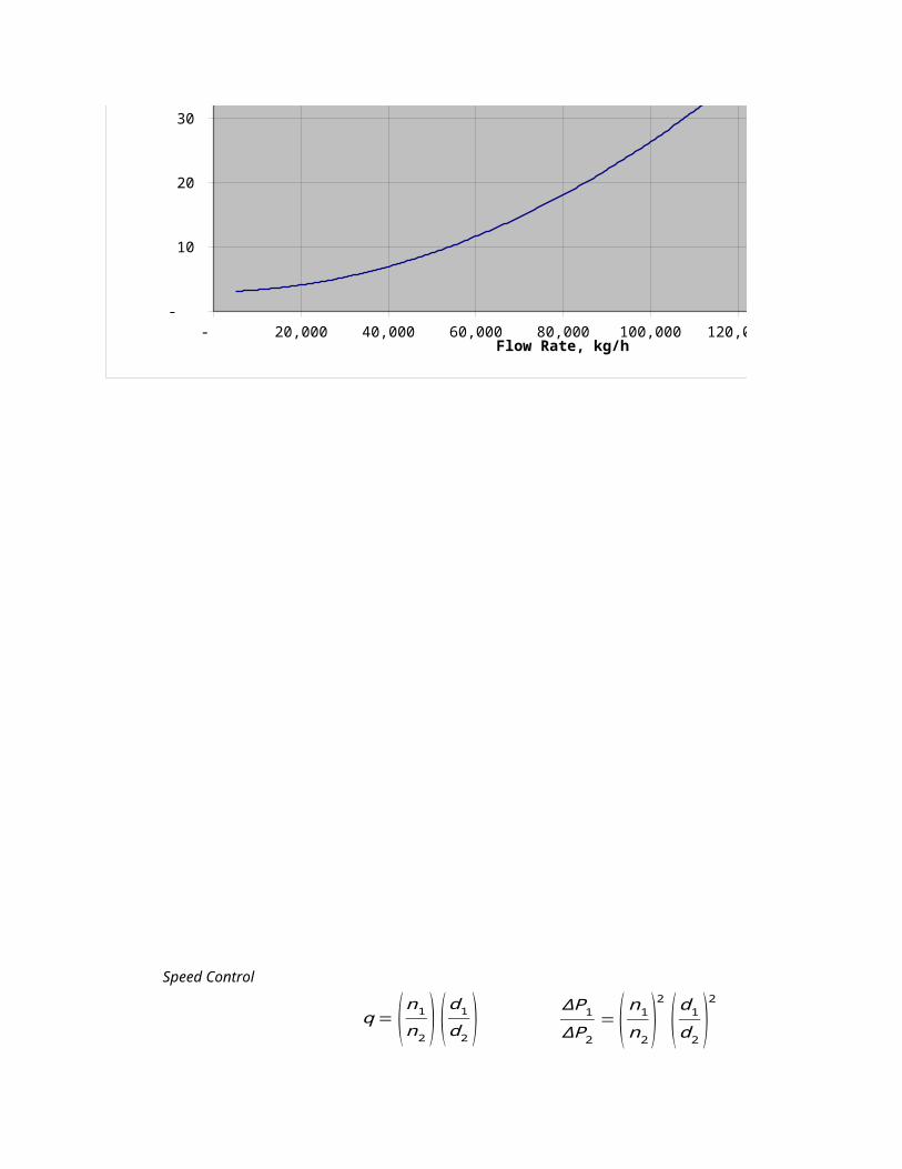
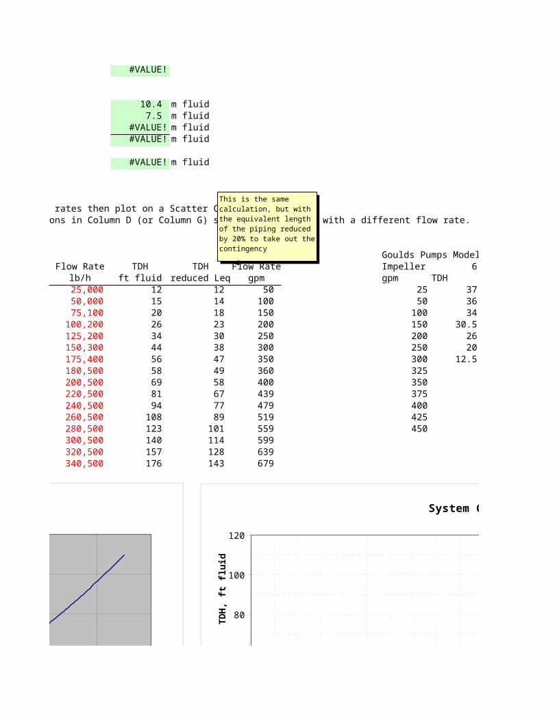
To construct a system curve, calculate the TDH at a number of flow rates then plot on a Scatter ChartThis can be done by replicating the column of inputs and calculations in Column D (or Column G) several times, each with a different flow rate.Or, a simple macro can perform the task, shown below
Flow Rate TDH Flow Ratekg/h m fluid lb/h
5,000 3 25,000 10,000 3 50,000 20,000 4 75,100 30,000 5 100,200 40,000 7 125,200 50,000 9 150,300 60,000 12 175,400 70,000 15 180,500 80,000 18 200,500 90,000 22 220,500 100,000 26 240,500 110,000 31 260,500 120,000 36 280,500 130,000 42 300,500 140,000 48 320,500 150,000 55 340,500
- 20,000 40,000 60,000 80,000 100,000 120,000 140,000 160,000 -
10
20
30
40
50
60
System Curve
Flow Rate, kg/h
TD
H,
m f
luid

- 20,000 40,000 60,000 80,000 100,000 120,000 140,000 160,000 -
10
20
30
40
50
60
System Curve
Flow Rate, kg/h
TD
H,
m f
luid

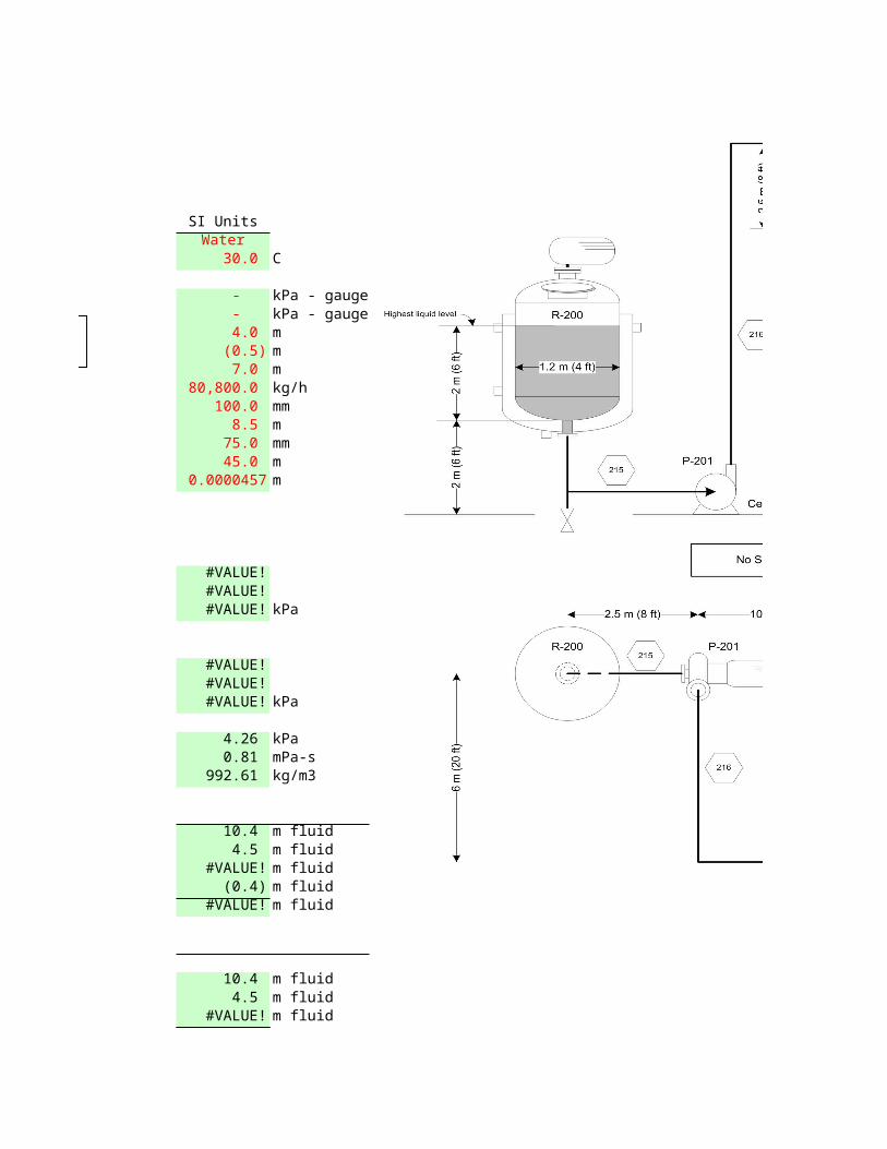
SI UnitsWater
30.0 C
- kPa - gauge - kPa - gauge 4.0 m (0.5) m 7.0 m 80,800.0 kg/h 100.0 mm 8.5 m 75.0 mm 45.0 m
0.0000457 m
#VALUE!#VALUE!#VALUE! kPa
#VALUE!#VALUE!#VALUE! kPa
4.26 kPa 0.81 mPa-s 992.61 kg/m3
10.4 m fluid 4.5 m fluid
#VALUE! m fluid (0.4) m fluid
#VALUE! m fluid
10.4 m fluid 4.5 m fluid
#VALUE! m fluid

#VALUE!
10.4 m fluid 7.5 m fluid
#VALUE! m fluid#VALUE! m fluid 0.283951
#VALUE! m fluid
To construct a system curve, calculate the TDH at a number of flow rates then plot on a Scatter ChartThis can be done by replicating the column of inputs and calculations in Column D (or Column G) several times, each with a different flow rate.
Goulds Pumps Model 3196, Size 3x4-7, 3560 rpmTDH TDH Flow Rate Impeller 5 5.5 6
ft fluid reduced Leq gpm gpm TDH 12 12 50 50 107 130 151 15 14 100 100 105 127 149 20 18 150 150 103 124 147 26 23 200 200 100 120.5 144 34 30 250 250 96 116 141 44 38 300 300 89 110 136 56 47 350 350 81 104 127 58 49 360 400 71 95 118 69 58 400 442 60 86 109 81 67 439 475 76 100 94 77 479 512 89 108 89 519 550 123 101 559 140 114 599 157 128 639 176 143 679
- 20,000 40,000 60,000 80,000 100,000 120,000 140,000 160,000 -
10
20
30
40
50
60
System Curve
Flow Rate, kg/h
TD
H,
m f
luid
0 100 200 300 400 500 600 700 8000
60
120
180
System Curve
Flow Rate, gpm
TD
H,
ft f
luid
This is the same calculation, but with the equivalent length of the piping reduced by 20% to take out the contingency
I68
This is the same calculation, but with the equivalent length of the piping reduced by 20% to take out the contingency
- 20,000 40,000 60,000 80,000 100,000 120,000 140,000 160,000 -
10
20
30
40
50
60
System Curve
Flow Rate, kg/h
TD
H,
m f
luid
0 100 200 300 400 500 600 700 8000
60
120
180
System Curve
Flow Rate, gpm
TD
H,
ft f
luid
0 100 200 300 400 500 600 7000
60
120
180
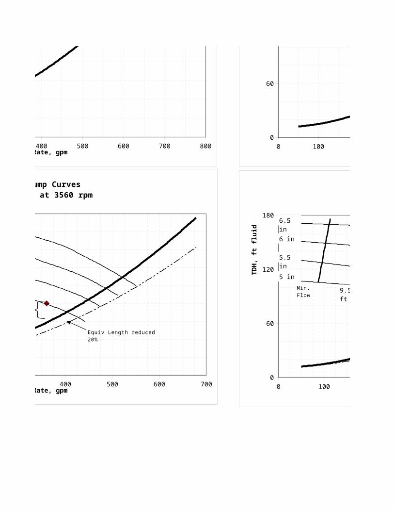
System and Pump CurvesANSI Size 3x4-7 at 3560 rpm
Flow Rate, gpm
TD
H,
ft f
luid
5 in
5.5 in
6 in
6.5 in
Equiv Length reduced 20%
Control Valve Pressure Drop

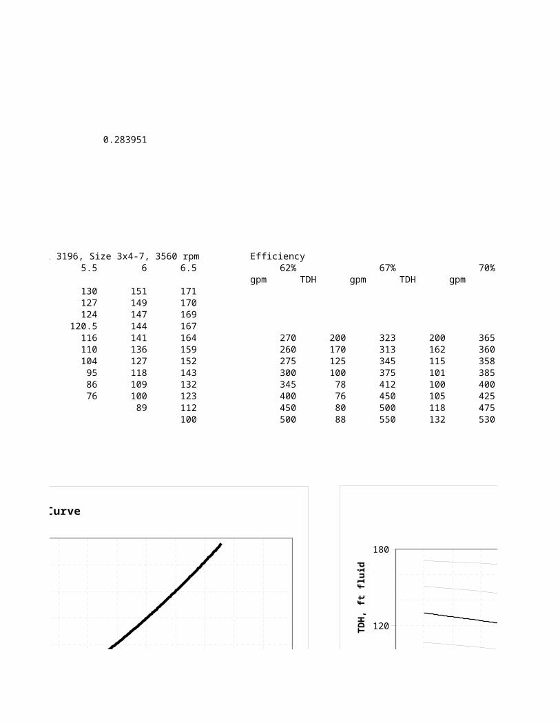
Goulds Pumps Model 3196, Size 3x4-7, 3560 rpm Efficiency Operating Point6.5 62% 67% 70%
gpm TDH gpm TDH gpm TDH gpm TDH171170 360 80169167164 270 200 323 200 365 190159 260 170 313 162 360 180152 275 125 345 115 358 160143 300 100 375 101 385 138132 345 78 412 100 400 133123 400 76 450 105 425 130112 450 80 500 118 475 135100 500 88 550 132 530 154
0 100 200 300 400 500 600 700 8000
60
120
180
System Curve
Flow Rate, gpm
TD
H,
ft f
luid
0 100 200 300 400 500 600 700 8000
60
120
180
System and Pump CurvesANSI Size 3x4-7 at 3560 rpm
Flow Rate, gpm
TD
H,
ft f
luid
62% 67% 70%
0 100 200 300 400 500 600 700 8000
60
120
180
System Curve
Flow Rate, gpm
TD
H,
ft f
luid
0 100 200 300 400 500 600 7000
60
120
180
System and Pump CurvesANSI Size 3x4-7 at 3560 rpm
Flow Rate, gpm
TD
H,
ft f
luid
5 in
5.5 in
6 in
6.5 in
Equiv Length reduced 20%
Control Valve Pressure Drop
0 100 200 300 400 500 600 700 8000
60
120
180
System and Pump CurvesANSI Size 3x4-7 at 3560 rpm
Flow Rate, gpm
TD
H,
ft f
luid
62% 67% 70%
0 100 200 300 400 500 600 7000
60
120
180
System and Pump CurvesANSI Size 3x4-7 at 3560 rpm
Flow Rate, gpm
TD
H,
ft f
luid
5 in
5.5 in
6 in
6.5 in
Equiv Length reduced 20%
62% 67% 70%
15 hp
20 hp
25 hp9.5 ft10 ft
11 ft12 ft
14 ft
Min. Flow

5.375" impeller 5 5.5 6 6.5gpm TDH Power
0 123.9 8.6 107.2147 129.7298 154.3892 181.1929115.9 120.4 10.5 104.186 126.0651 150.0279 176.0744231.9 112.6 12.1 97.43645 117.8981 140.3085 164.6676347.8 98.3 13.3 85.0622 102.9253 122.4896 143.7551
360 96.3 13.5 83.33153 100.8312 119.9974 140.8303463.8 72 14.3 62.30395 75.38778 89.71769 105.2937
0 100 200 300 400 500 600 700 8000
60
120
180
System and Pump CurvesANSI Size 3x4-7 at 3560 rpm
Flow Rate, gpm
TD
H,
ft f
luid
62% 67% 70%

0 100 200 300 400 500 600 700 8000
60
120
180
System and Pump CurvesANSI Size 3x4-7 at 3560 rpm
Flow Rate, gpm
TD
H,
ft f
luid
62% 67% 70%
0 100 200 300 400 500 600 7000
60
120
180
System and Pump CurvesANSI Size 3x4-7 at 3560 rpm
Flow Rate, gpm
TD
H,
ft f
luid
5 in
5.5 in
6 in
6.5 in
Equiv Length reduced 20%
62% 67% 70%
15 hp
20 hp
25 hp9.5 ft10 ft
11 ft12 ft
14 ft
Min. Flow

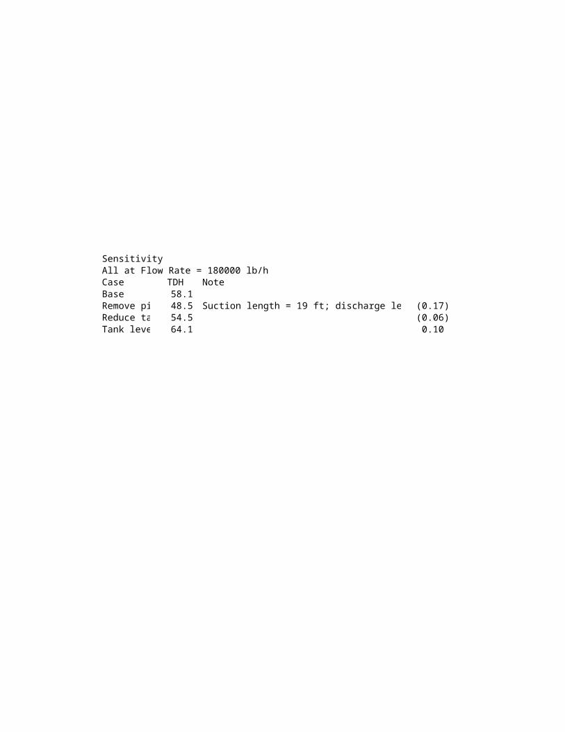
SensitivityAll at Flow Rate = 180000 lb/hCase TDH NoteBase 58.1 Remove piping contingency 48.5 Suction length = 19 ft; discharge length = 120 (0.17)Reduce tank level to 0 54.5 (0.06)Tank level 0 with contingency 64.1 0.10
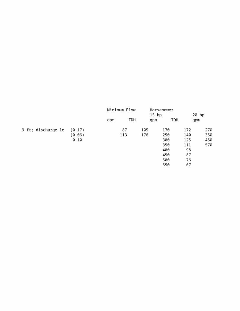
Minimum Flow Horsepower NPSH required15 hp 20 hp 25 hp 9.5 ft
gpm TDH gpm TDH gpm TDH gpm TDH gpm TDH
87 105 170 172 270 184 400 176 170 102113 176 250 140 350 157 450 158 200 125
300 125 450 121 500 137 250 163350 111 570 77 600 100 270 182400 98450 87500 76550 67
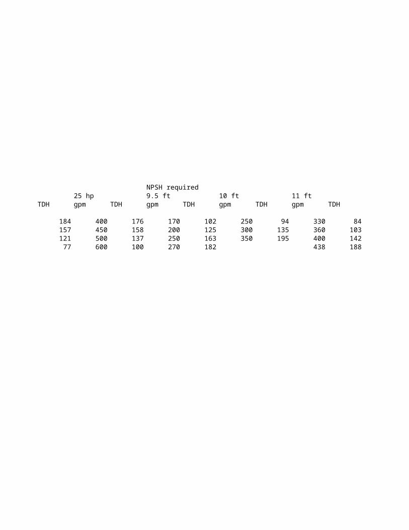
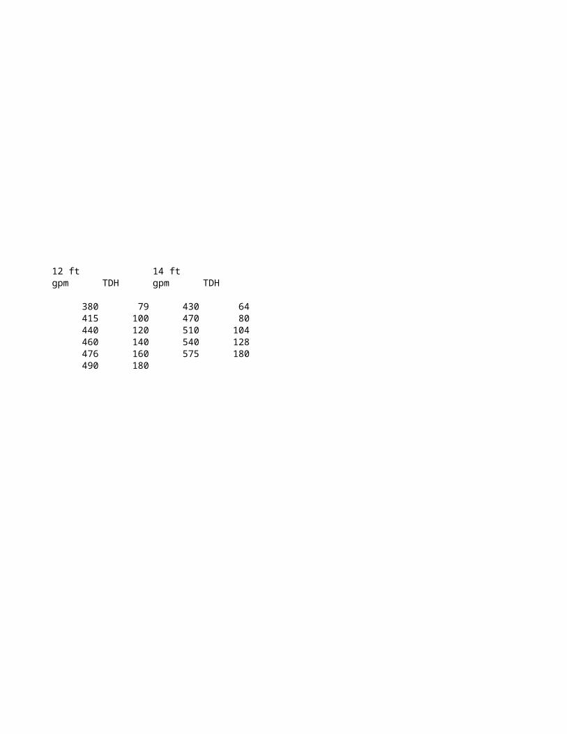
10 ft 11 ft 12 ft 14 ftgpm TDH gpm TDH gpm TDH gpm TDH
250 94 330 84 380 79 430 64300 135 360 103 415 100 470 80350 195 400 142 440 120 510 104
438 188 460 140 540 128476 160 575 180490 180
Inputs US UnitsPumped liquid WaterTemperature 86.0 F
Head pressure 0.0 psigDischarge pressure 0.0 psigLiquid height above datum 12.0 ftPump suction height above datum 1.5 ftPump discharge height above datum 23.0 Flow rate 180,000.0 lb/hSuction pipe inside diameter 4.0 inEquivalent length of suction pipe 27.0 ftDischarge pipe inside diameter 3.0 inEquivalent length of discharge pipe 150.0 ftRoughness 0.00015 ft
OutputSuction Pipe - Line 215Reynolds Number #VALUE!Friction Factor #VALUE!Pressure Drop due to friction #VALUE! psi
Discharge Pipe - Line 216Reynolds Number #VALUE!Friction Factor #VALUE!Pressure Drop due to friction #VALUE! psi
Vapor Pressure 0.62 psiaViscosity 0.81 cPDensity 62.56 lb/ft3
NPSH availableHead pressure 33.9 ft fluidFluid pressure 10.5 Friction loss #VALUE!Vapor pressure reduction (1.4)
#VALUE! ft fluid
Total Dynamic HeadSuction PressureHead pressure 33.9 ft fluidFluid pressure 10.5 ft fluidFriction loss #VALUE! ft fluid
Problem Statement:Create a System Curve and Pump Curves at 1800 rpm
Primary Input Variable

Net Suction Pressure #VALUE! ft fluid
DischargeHead pressure 33.9 ft fluidFluid pressure 21.5 ft fluidFriction loss #VALUE! ft fluidNet Discharge Pressure #VALUE! ft fluid
Differential Pressure (TDH) #VALUE! ft fluid
To construct a system curve, calculate the TDH at a number of flow rates then plot on a Scatter ChartThis can be done by replicating the column of inputs and calculations in Column D (or Column G) several times, each with a different flow rate.Or, a simple macro can perform the task, shown below
Flow Rate TDH Flow Ratekg/h m fluid lb/h
5,000 3 25,000 10,000 3 50,000 20,000 4 75,100 30,000 5 100,200 40,000 7 125,200 50,000 9 150,300 60,000 12 175,400 70,000 15 180,500 80,000 18 200,500 90,000 22 220,500 100,000 26 240,500 110,000 31 260,500 120,000 36 280,500 130,000 42 300,500 140,000 48 320,500 150,000 55 340,500
- 20,000 40,000 60,000 80,000 100,000 120,000 140,000 160,000 -
10
20
30
40
50
60
System Curve
Flow Rate, kg/h
TD
H,
m f
luid
Speed Control
- 20,000 40,000 60,000 80,000 100,000 120,000 140,000 160,000 -
10
20
30
40
50
60
System Curve
Flow Rate, kg/h
TD
H,
m f
luid
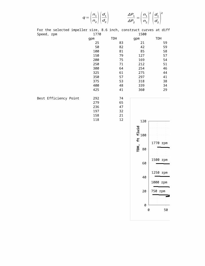
q = ( n1n2 ) ( d1d2)ΔP1ΔP2
= ( n1n2 )2
( d1d2 )2
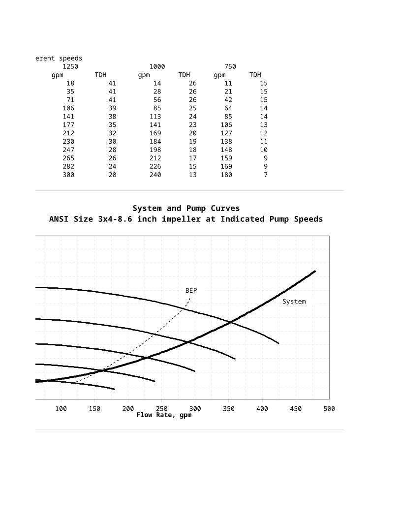
For the selected impeller size, 8.6 inch, construct curves at different speedsSpeed, rpm 1770 1500 1250
gpm TDH gpm TDH gpm 25 83 21 59 18 50 82 42 59 35 100 81 85 58 71 150 79 127 57 106 200 75 169 54 141 250 71 212 51 177 300 64 254 46 212 325 61 275 44 230 350 57 297 41 247 375 53 318 38 265 400 48 339 34 282 425 41 360 29 300
Best Efficiency Point 292 74 279 65 236 47 197 32 158 21 118 12
0 50 100 150 200 250 300 350 400 450 5000
20
40
60
80
100
120
System and Pump CurvesANSI Size 3x4-8.6 inch impeller at Indicated Pump Speeds
Flow Rate, gpm
TD
H,
ft f
luid
BEP
1770 rpm
1500 rpm
1250 rpm
1000 rpm
750 rpm
System
q = ( n1n2 ) ( d1d2)ΔP1ΔP2
= ( n1n2 )2
( d1d2 )2
SI UnitsWater
30.0 C
- kPa - gauge - kPa - gauge 4.0 m (0.5) m 7.0 m 80,800.0 kg/h 100.0 mm 8.5 m 75.0 mm 45.0 m
0.0000457 m
#VALUE!#VALUE!#VALUE! kPa
#VALUE!#VALUE!#VALUE! kPa
4.26 kPa 0.81 mPa-s 992.61 kg/m3
10.4 m fluid 4.5 m fluid
#VALUE! m fluid (0.4) m fluid
#VALUE! m fluid
10.4 m fluid 4.5 m fluid
#VALUE! m fluid
#VALUE!
10.4 m fluid 7.5 m fluid
#VALUE! m fluid#VALUE! m fluid 0.283951
#VALUE! m fluid
To construct a system curve, calculate the TDH at a number of flow rates then plot on a Scatter ChartThis can be done by replicating the column of inputs and calculations in Column D (or Column G) several times, each with a different flow rate.
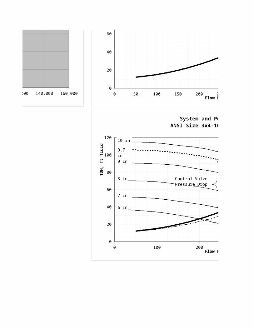
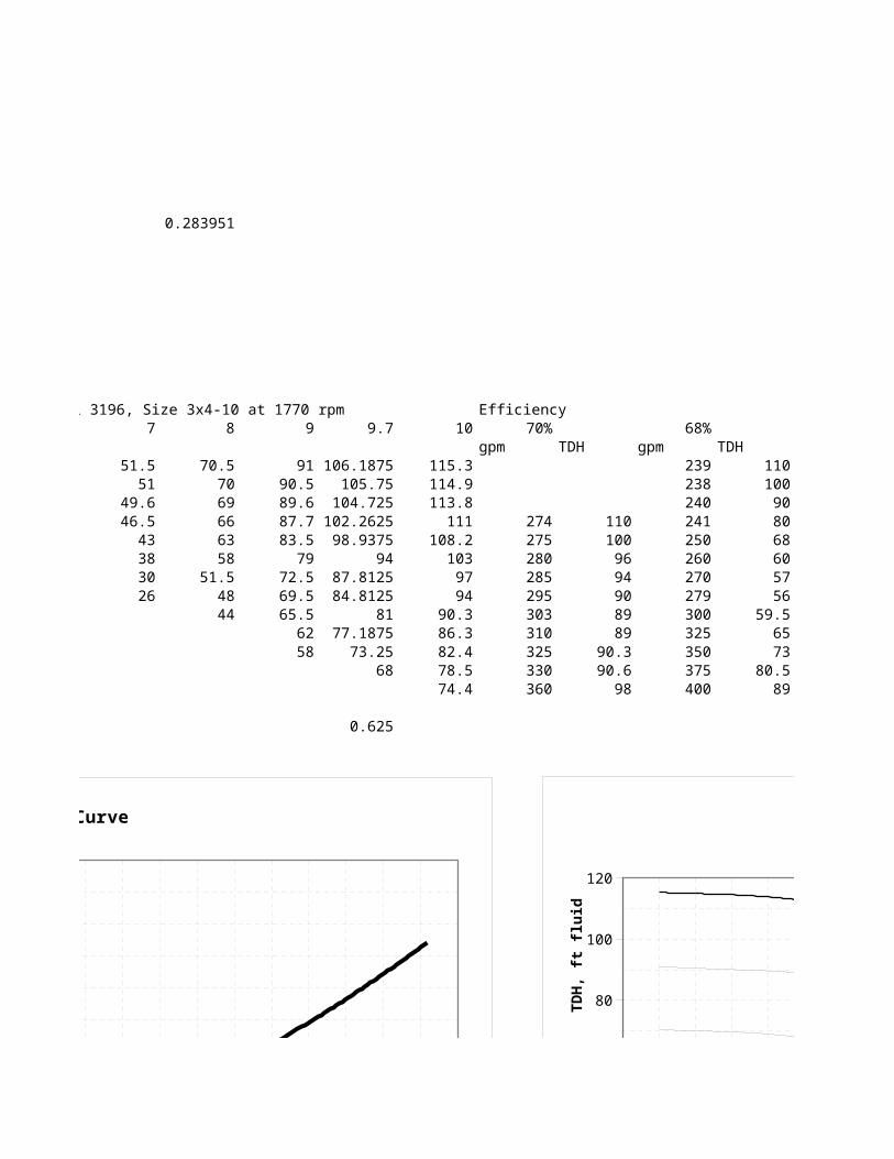
Goulds Pumps Model 3196, Size 3x4-10 at 1770 rpmTDH TDH Flow Rate Impeller 6 7 8
ft fluid reduced Leq gpm gpm TDH 12 12 50 25 37 51.5 70.5 15 14 100 50 36 51 70 20 18 150 100 34 49.6 69 26 23 200 150 30.5 46.5 66 34 30 250 200 26 43 63 44 38 300 250 20 38 58 56 47 350 300 12.5 30 51.5 58 49 360 325 26 48 69 58 400 350 44 81 67 439 375 94 77 479 400 108 89 519 425 123 101 559 450 140 114 599 157 128 639 176 143 679
- 20,000 40,000 60,000 80,000 100,000 120,000 140,000 160,000 -
10
20
30
40
50
60
System Curve
Flow Rate, kg/h
TD
H,
m f
luid
0 50 100 150 200 250 300 350 400 450 5000
20
40
60
80
100
120
System Curve
Flow Rate, gpm
TD
H,
ft f
luid
This is the same calculation, but with the equivalent length of the piping reduced by 20% to take out the contingency
I68
This is the same calculation, but with the equivalent length of the piping reduced by 20% to take out the contingency
- 20,000 40,000 60,000 80,000 100,000 120,000 140,000 160,000 -
10
20
30
40
50
60
System Curve
Flow Rate, kg/h
TD
H,
m f
luid
0 50 100 150 200 250 300 350 400 450 5000
20
40
60
80
100
120
System Curve
Flow Rate, gpm
TD
H,
ft f
luid
0 100 200 300 400 5000
20
40
60
80
100
120
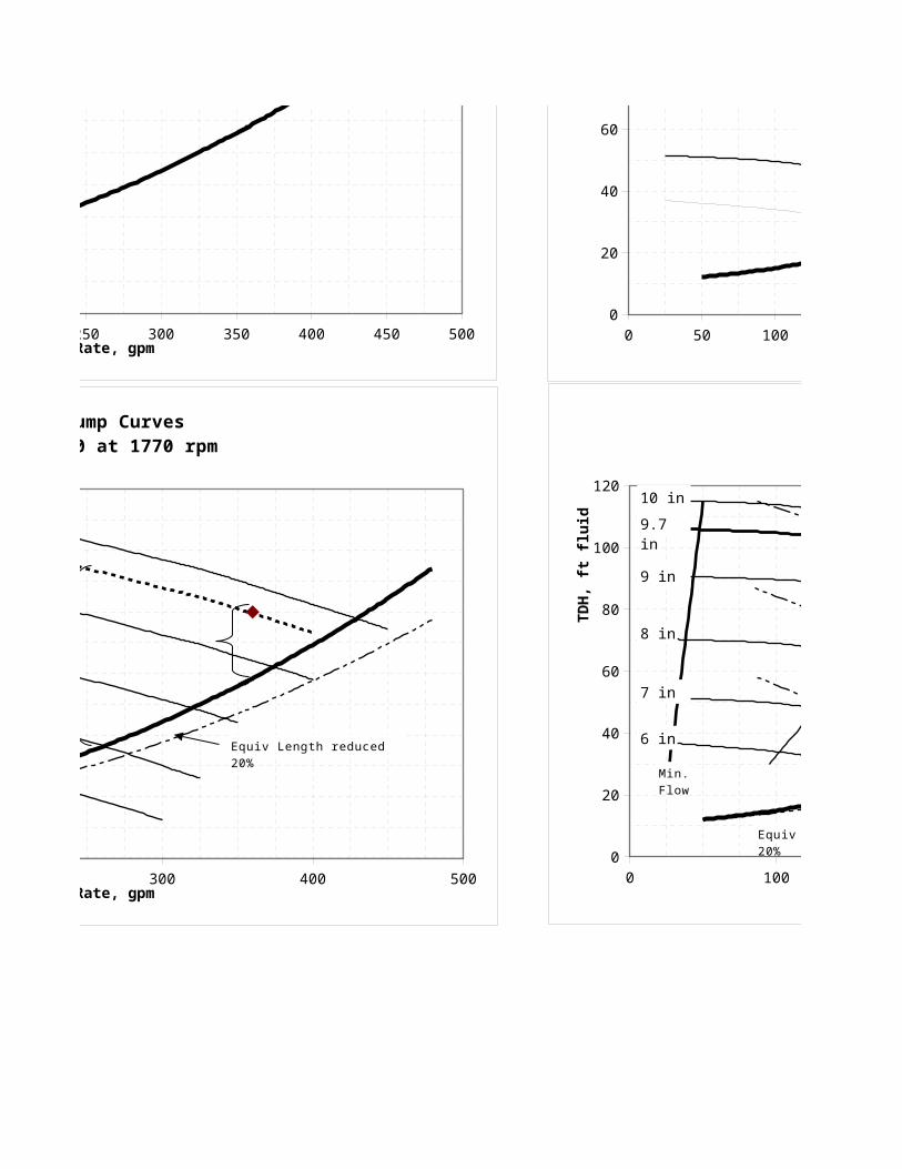
System and Pump CurvesANSI Size 3x4-10 at 1770 rpm
Flow Rate, gpm
TD
H,
ft f
luid
6 in
7 in
8 in
9 in
Equiv Length reduced 20%
Control Valve Pressure Drop
10 in
9.7 in
1000 750TDH gpm TDH gpm TDH
41 14 26 11 15 41 28 26 21 15 41 56 26 42 15 39 85 25 64 14 38 113 24 85 14 35 141 23 106 13 32 169 20 127 12 30 184 19 138 11 28 198 18 148 10 26 212 17 159 9 24 226 15 169 9 20 240 13 180 7
0 50 100 150 200 250 300 350 400 450 5000
20
40
60
80
100
120
System and Pump CurvesANSI Size 3x4-8.6 inch impeller at Indicated Pump Speeds
Flow Rate, gpm
TD
H,
ft f
luid
BEP
1770 rpm
1500 rpm
1250 rpm
1000 rpm
750 rpm
System

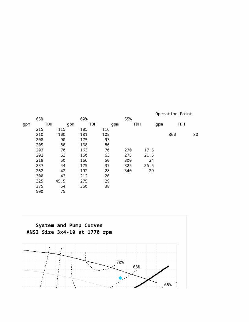
Goulds Pumps Model 3196, Size 3x4-10 at 1770 rpm Efficiency9 9.7 10 70% 68% 65% 60%
gpm TDH gpm TDH gpm TDH gpm91 106.1875 115.3 239 110 215 115 185
90.5 105.75 114.9 238 100 210 100 18189.6 104.725 113.8 240 90 208 90 17587.7 102.2625 111 274 110 241 80 205 80 16883.5 98.9375 108.2 275 100 250 68 203 70 163
79 94 103 280 96 260 60 202 63 16072.5 87.8125 97 285 94 270 57 218 50 16669.5 84.8125 94 295 90 279 56 237 44 17565.5 81 90.3 303 89 300 59.5 262 42 192
62 77.1875 86.3 310 89 325 65 300 43 21258 73.25 82.4 325 90.3 350 73 325 45.5 275
68 78.5 330 90.6 375 80.5 375 54 36074.4 360 98 400 89 500 75
0.625
0 50 100 150 200 250 300 350 400 450 5000
20
40
60
80
100
120
System Curve
Flow Rate, gpm
TD
H,
ft f
luid
0 50 100 150 200 250 300 350 400 450 5000
20
40
60
80
100
120
System and Pump CurvesANSI Size 3x4-10 at 1770 rpm
Flow Rate, gpm
TD
H,
ft f
luid
65%
68%70%
60%
55%
0 50 100 150 200 250 300 350 400 450 5000
20
40
60
80
100
120
System Curve
Flow Rate, gpm
TD
H,
ft f
luid
0 100 200 300 400 5000
20
40
60
80
100
120
System and Pump CurvesANSI Size 3x4-10 at 1770 rpm
Flow Rate, gpm
TD
H,
ft f
luid
6 in
7 in
8 in
9 in
Equiv Length reduced 20%
Control Valve Pressure Drop
10 in
9.7 in
0 50 100 150 200 250 300 350 400 450 5000
20
40
60
80
100
120
System and Pump CurvesANSI Size 3x4-10 at 1770 rpm
Flow Rate, gpm
TD
H,
ft f
luid
65%
68%70%
60%
55%
0 100 200 300 400 5000
20
40
60
80
100
120
System and Pump CurvesANSI Size 3x4-10 at 1770 rpm
Flow Rate, gpm
TD
H,
ft f
luid
6 in
7 in
8 in
9 in
Equiv Length reduced 20%
65%
68%
70%
3 hp5 hp
7.5 hp
2 ft 3 ft 4 ft 5 ft
6 ft
Min. Flow
10 in
10 hp
60%
55%
65% 68%
7 ft9.7 in
Operating Point55% 5.375" impeller
TDH gpm TDH gpm TDH gpm TDH Power116 0 123.9 8.6105 360 80 115.9 120.4 10.5
93 231.9 112.6 12.180 347.8 98.3 13.370 230 17.5 360 96.3 13.563 275 21.5 463.8 72 14.350 300 2437 325 26.528 340 29262938
0 50 100 150 200 250 300 350 400 450 5000
20
40
60
80
100
120
System and Pump CurvesANSI Size 3x4-10 at 1770 rpm
Flow Rate, gpm
TD
H,
ft f
luid
65%
68%70%
60%
55%

0 50 100 150 200 250 300 350 400 450 5000
20
40
60
80
100
120
System and Pump CurvesANSI Size 3x4-10 at 1770 rpm
Flow Rate, gpm
TD
H,
ft f
luid
65%
68%70%
60%
55%
0 100 200 300 400 5000
20
40
60
80
100
120
System and Pump CurvesANSI Size 3x4-10 at 1770 rpm
Flow Rate, gpm
TD
H,
ft f
luid
6 in
7 in
8 in
9 in
Equiv Length reduced 20%
65%
68%
70%
3 hp5 hp
7.5 hp
2 ft 3 ft 4 ft 5 ft
6 ft
Min. Flow
10 in
10 hp
60%
55%
65% 68%
7 ft9.7 in
Sensitivity5 5.5 6 6.5 All at Flow Rate = 180000 lb/h
Case TDH Note107.214710654408 129.7298 154.3892 181.1929 Base 58.1 104.186046511628 126.0651 150.0279 176.0744 Remove pip 48.5 Suction length = 19 ft; discharge length = 12097.4364521362899 117.8981 140.3085 164.6676 Reduce tank 54.5 85.0621957815035 102.9253 122.4896 143.7551 Tank level 64.1 83.3315305570579 100.8312 119.9974 140.830362.3039480800433 75.38778 89.71769 105.2937

Minimum Flow Horsepower3 hp 5 hp
gpm TDH gpm TDH gpm
Suction length = 19 ft; discharge length = 120 (0.17) 27 30 87 58 85 (0.06) 50 115 150 46 175 0.10 200 37.5 225
250 28.5 275300 20.5 325330 15 370

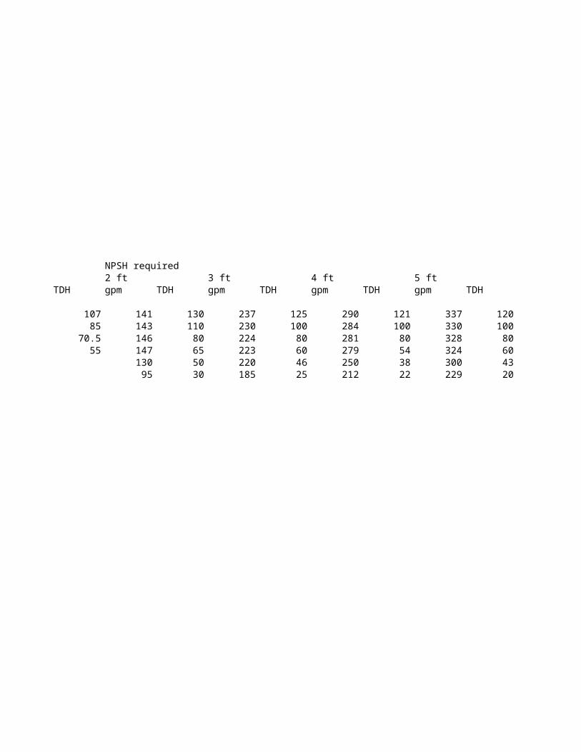
NPSH required7.5 hp 10 hp 2 ft 3 ft 4 ft
TDH gpm TDH gpm TDH gpm TDH gpm TDH gpm
87 87 115 260 107 141 130 237 125 29070 175 99.5 325 85 143 110 230 100 284
59.5 250 83 375 70.5 146 80 224 80 28148 300 69 438 55 147 65 223 60 27936 350 54.5 130 50 220 46 25025 400 38.5 95 30 185 25 212
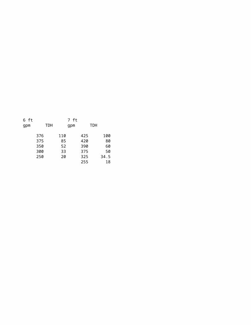
5 ft 6 ft 7 ftTDH gpm TDH gpm TDH gpm TDH
121 337 120 376 110 425 100100 330 100 375 85 420 80
80 328 80 350 52 390 6054 324 60 300 33 375 5038 300 43 250 20 325 34.522 229 20 255 18

Valve CoefficientFluid density 62.56 lb/ft3
Flow Rate Pressure Drop Coefficientgpm ft fluid psi Cv
360 20 8.69 122.29 360 30 13.03 99.85 250 60 26.07 49.03
Check for CavitationVapor pressure -14.08 psigCritical pressure 218.3 atm 3209.01 psia
Flow Rate Upstream Pressuregpm ft fluid ft fluid ft fluid psi psi
360 36.6 83 119.6 51.96 38.93 5.07 360 36.6 83 63.8 27.73 19.04 4.81 250 37.5 96 133.5 58.00 31.93 2.77 250 37.5 96 93.8 40.77 14.70 2.10
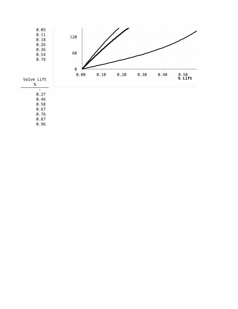
Application and Valve Curves
Installation Curve Flow Rate Pump TDH System Valve Pressure Drop Coefficient Full Open
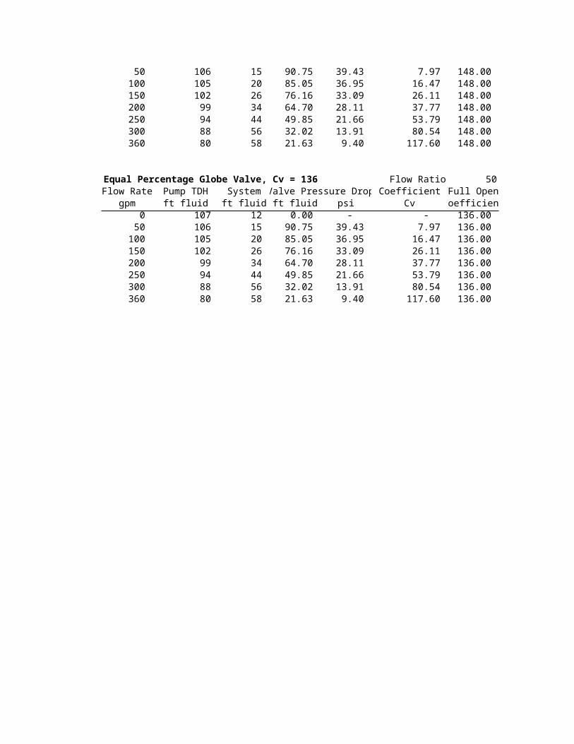
gpm ft fluid ft fluid ft fluid psi Cv Coefficient 0 107 12 - - - 117.60 50 106 15 90.75 39.43 7.97 117.60 100 105 20 85.05 36.95 16.47 117.60 150 102 26 76.16 33.09 26.11 117.60 200 99 34 64.70 28.11 37.77 117.60 250 94 44 49.85 21.66 53.79 117.60 300 88 56 32.02 13.91 80.54 117.60 360 80 58 21.63 9.40 117.60 117.60
Linear Globe Valve, Cv = 148 Flow Rate Pump TDH System Valve Pressure Drop Coefficient Full Open
gpm ft fluid ft fluid ft fluid psi Cv Coefficient 0 107 12 0.00 - - 148.00
Net Suction Pressure
Pump TDH
Downstream Pressure
Cavitation Index
Problem Statement:Size the control valve and create valve curves
50 106 15 90.75 39.43 7.97 148.00 100 105 20 85.05 36.95 16.47 148.00 150 102 26 76.16 33.09 26.11 148.00 200 99 34 64.70 28.11 37.77 148.00 250 94 44 49.85 21.66 53.79 148.00 300 88 56 32.02 13.91 80.54 148.00 360 80 58 21.63 9.40 117.60 148.00
Equal Percentage Globe Valve, Cv = 136 Flow Ratio 50 Flow Rate Pump TDH System Valve Pressure Drop Coefficient Full Open
gpm ft fluid ft fluid ft fluid psi Cv Coefficient 0 107 12 0.00 - - 136.00 50 106 15 90.75 39.43 7.97 136.00 100 105 20 85.05 36.95 16.47 136.00 150 102 26 76.16 33.09 26.11 136.00 200 99 34 64.70 28.11 37.77 136.00 250 94 44 49.85 21.66 53.79 136.00 300 88 56 32.02 13.91 80.54 136.00 360 80 58 21.63 9.40 117.60 136.00
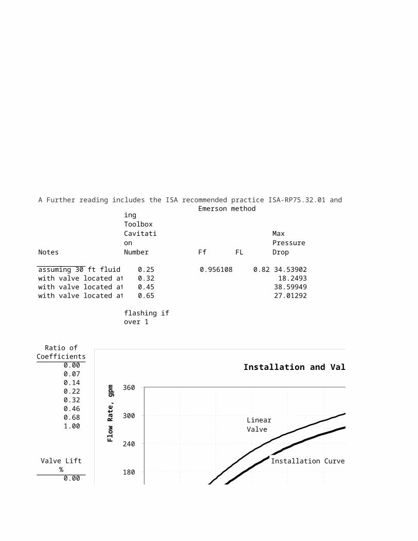
Emerson method
Notes Ff FL
assuming 30 ft fluid press 0.25 0.956108 0.82 34.53902with valve located at pipe 0.32 18.2493with valve located at pum 0.45 38.59949with valve located at pipe 0.65 27.01292
flashing ifover 1
Ratio ofCoefficients
0.00 0.07 0.14 0.22 0.32 0.46 0.68 1.00
Valve Lift%
0.00
A Further reading includes the ISA recommended practice ISA-RP75.32.01 and Instrument Engineer’s Handbook, 4th ed. Chapter 6.15.
Engineering Toolbox Cavitation Number
Max Pressure Drop
0.00 0.10 0.20 0.30 0.40 0.50 0.60 0.70 0.80 0.90 1.00 0
60
120
180
240
300
360
Installation and Valve Curves
% Lift
Flo
w R
ate,
gp
m
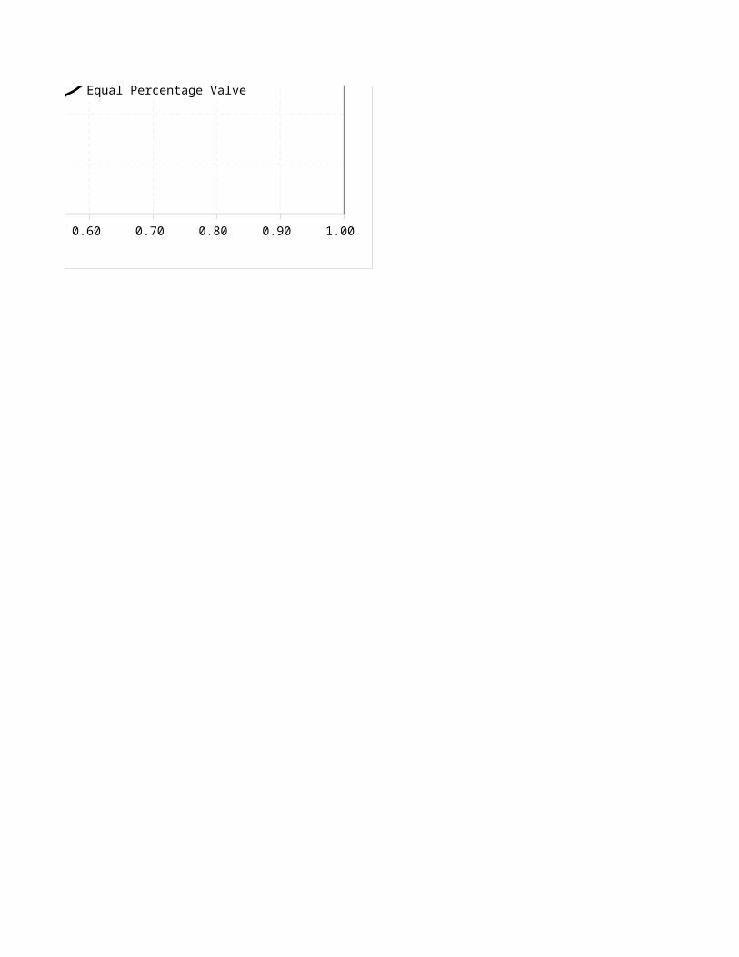
Equal Percentage Valve
Linear Valve
Installation Curve

0.05 0.11 0.18 0.26 0.36 0.54 0.79
Valve Lift%
- 0.27 0.46 0.58 0.67 0.76 0.87 0.96
0.00 0.10 0.20 0.30 0.40 0.50 0.60 0.70 0.80 0.90 1.00 0
60
120
180
240
300
360
Installation and Valve Curves
% Lift
Flo
w R
ate,
gp
m
Equal Percentage Valve
Linear Valve
Installation Curve
A Further reading includes the ISA recommended practice ISA-RP75.32.01 and Instrument Engineer’s Handbook, 4th ed. Chapter 6.15.
0.00 0.10 0.20 0.30 0.40 0.50 0.60 0.70 0.80 0.90 1.00 0
60
120
180
240
300
360
Installation and Valve Curves
% Lift
Flo
w R
ate,
gp
m
Equal Percentage Valve
Linear Valve
Installation Curve
0.00 0.10 0.20 0.30 0.40 0.50 0.60 0.70 0.80 0.90 1.00 0
60
120
180
240
300
360
Installation and Valve Curves
% Lift
Flo
w R
ate,
gp
m
Equal Percentage Valve
Linear Valve
Installation Curve
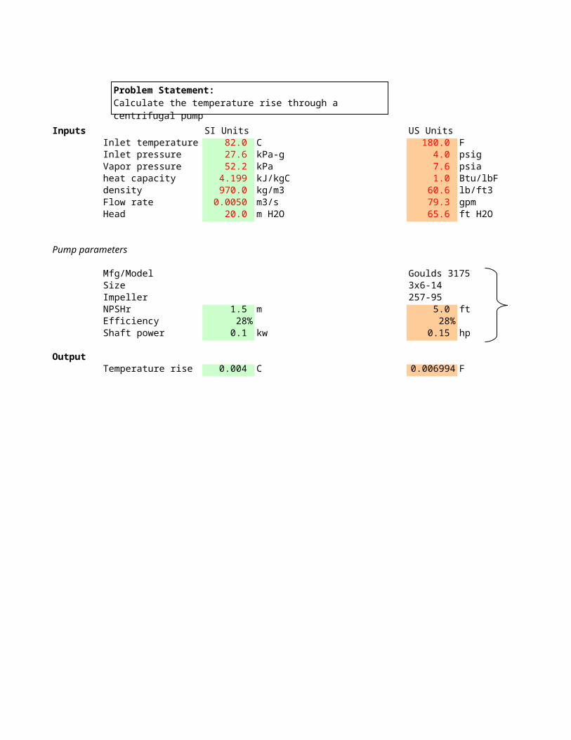
Inputs SI Units US UnitsInlet temperature 82.0 C 180.0 FInlet pressure 27.6 kPa-g 4.0 psigVapor pressure 52.2 kPa 7.6 psiaheat capacity 4.199 kJ/kgC 1.0 Btu/lbFdensity 970.0 kg/m3 60.6 lb/ft3Flow rate 0.0050 m3/s 79.3 gpmHead 20.0 m H2O 65.6 ft H2O
Pump parameters
Mfg/Model Goulds 3175Size 3x6-14Impeller 257-95NPSHr 1.5 m 5.0 ftEfficiency 28% 28%
OutputHyraulic power 0.952 kw 1.274 hp
Shaft power 3.40 kw 4.55 hp
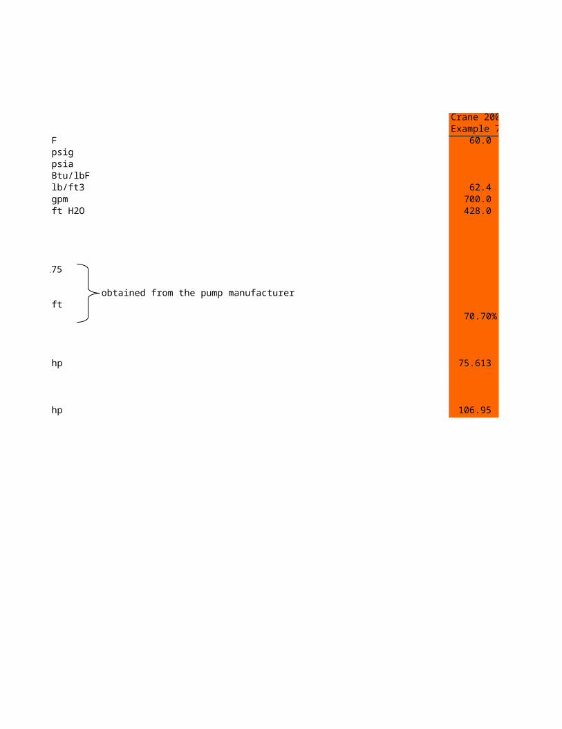
Problem Statement:Calculate the hydraulic and shaft (brake) power of a pump

Crane 2009Example 7-34 60.0 F
62.4 lb/ft3 700.0 gpm 428.0 ft
obtained from the pump manufacturer
70.70%
75.613 hydraulic hp
106.95 bhp
hydraulic hp
(Crane answer is 107 bhp)

Inputs SI Units US UnitsInlet temperature 82.0 C 180.0 FInlet pressure 27.6 kPa-g 4.0 psigVapor pressure 52.2 kPa 7.6 psiaheat capacity 4.199 kJ/kgC 1.0 Btu/lbFdensity 970.0 kg/m3 60.6 lb/ft3Flow rate 0.0050 m3/s 79.3 gpmHead 20.0 m H2O 65.6 ft H2O
Pump parameters
Mfg/Model Goulds 3175Size 3x6-14Impeller 257-95 obtained from the pump manufacturerNPSHr 1.5 m 5.0 ftEfficiency 28% 28%Shaft power 0.1 kw 0.15 hp
OutputTemperature rise 0.004 C 0.006994 F
Problem Statement:Calculate the temperature rise through a centrifugal pump
obtained from the pump manufacturer

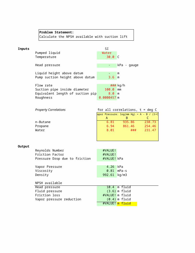
Inputs SI USPumped liquid Water WaterTemperature 30.0 C 86
Head pressure - kPa - gauge -
Liquid height above datum - m - Pump suction height above datum 3.6 m 12.0
Flow rate 80,800.0 kg/h 193,200.0 Suction pipe inside diameter 100.0 mm 4.0 Equivalent length of suction pipe 8.0 m 26.0 Roughness 0.0000457 m 0.00015
Property Correlations for all correlations, t = deg CVapor Pressure: log(mm Hg) = A - B / (t+C) Viscosity: ln(cP) = A + B / (C+t)
A B C An-Butane 6.81 935.86 238.73 (12.95)Propane 6.94 861.46 254.46 30.62 Water 8.01 1,701.79 231.47 (3.63)
OutputReynolds Number #VALUE! #VALUE!Friction Factor #VALUE! #VALUE!Pressure Drop due to friction #VALUE! kPa #VALUE!
Vapor Pressure 4.26 kPa 0.62 Viscosity 0.81 mPa-s 0.81 Density 992.61 kg/m3 62.56
NPSH availableHead pressure 10.4 m fluid 33.8 Fluid pressure (3.6) m fluid (12.0)Friction loss #VALUE! m fluid #VALUE!Vapor pressure reduction (0.4) m fluid (1.4)
#VALUE! m fluid #VALUE!
Problem Statement:Calculate the NPSH available with suction lift
F
psig
ftft
lb/hinftft
Viscosity: ln(cP) = A + B / (C+t) Density: kg/m3 = m t + b Density: lb/ft3 = m t + b
B C m b m b 13,089.6 1,152.98 (1.14) 600.14 (0.07) 37.07 102,599.9 (3,138.68) (1.40) 527.11 (0.08) 32.37 544.02 129.06 (0.46) 1,006.35 (0.06) 64.24
psi
psiacPlb/ft3
ft fluid
ft fluid
Water, 30 C
3.6
m (
12 ft
)
Atmosphere101 kPa
(14.7 psia)
Friction Loss0.6 m H2O(2 ft H2O)
dept
h

Crane 2009Example 7-34
Water60 F
5.0 psig
10.0 ft 35.0 ft 400.0 gal/m 203,312 lb/h
0.26 psia 0.10 cP 63.37 lb/ft3
44.8 ft fluid (25.0) (6.0) ft fluid (given) (0.6) 13.2 ft fluid(Crane answer is 13.9 ft)
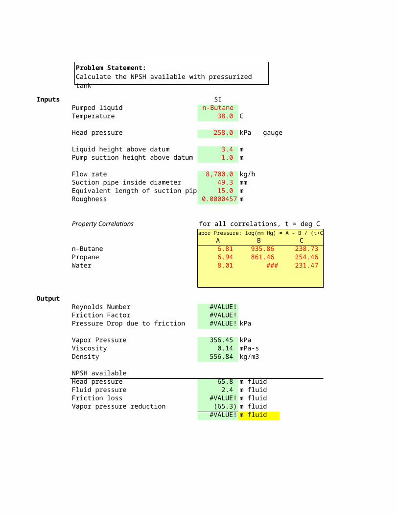
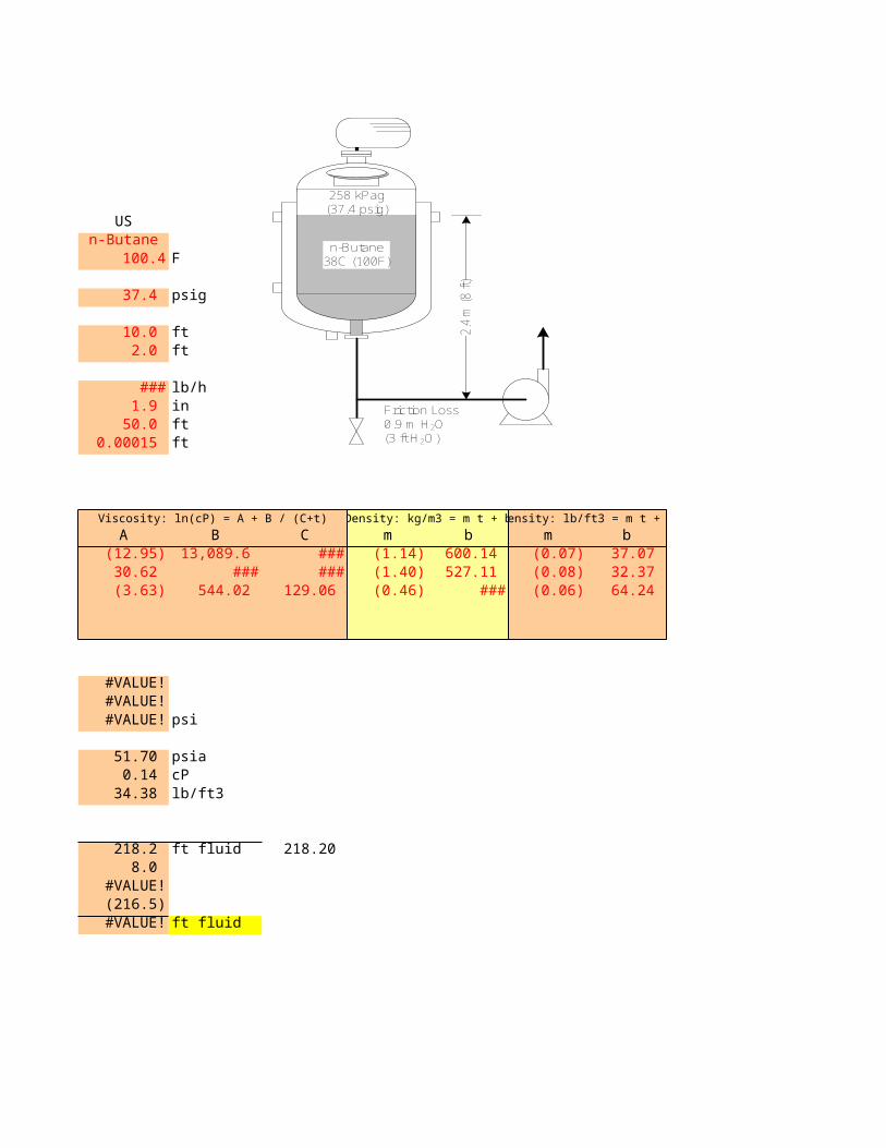
Inputs SI USPumped liquid n-Butane n-ButaneTemperature 38.0 C 100.4
Head pressure 258.0 kPa - gauge 37.4
Liquid height above datum 3.4 m 10.0 Pump suction height above datum 1.0 m 2.0
Flow rate 8,700.0 kg/h 19,140.0 Suction pipe inside diameter 49.3 mm 1.9 Equivalent length of suction pipe 15.0 m 50.0 Roughness 0.0000457 m 0.00015
Property Correlations for all correlations, t = deg CVapor Pressure: log(mm Hg) = A - B / (t+C) Viscosity: ln(cP) = A + B / (C+t)
A B C An-Butane 6.81 935.86 238.73 (12.95)Propane 6.94 861.46 254.46 30.62 Water 8.01 1,701.79 231.47 (3.63)
OutputReynolds Number #VALUE! #VALUE!Friction Factor #VALUE! #VALUE!Pressure Drop due to friction #VALUE! kPa #VALUE!
Vapor Pressure 356.45 kPa 51.70 Viscosity 0.14 mPa-s 0.14 Density 556.84 kg/m3 34.38
NPSH availableHead pressure 65.8 m fluid 218.2 Fluid pressure 2.4 m fluid 8.0 Friction loss #VALUE! m fluid #VALUE!Vapor pressure reduction (65.3) m fluid (216.5)
#VALUE! m fluid #VALUE!
Problem Statement:Calculate the NPSH available with pressurized tank

F
psig
ftft
lb/hinftft
Viscosity: ln(cP) = A + B / (C+t) Density: kg/m3 = m t + b Density: lb/ft3 = m t + b
B C m b m b 13,089.6 1,152.98 (1.14) 600.14 (0.07) 37.07 102,599.9 (3,138.68) (1.40) 527.11 (0.08) 32.37 544.02 129.06 (0.46) 1,006.35 (0.06) 64.24
psi
psiacPlb/ft3
ft fluid 218.20
ft fluid
n-Butane38C (100F)
258 kPag(37.4 psig)
2.4
m (
8 ft)
Friction Loss0.9 m H2O(3 ft H2O)

Inputs SI USFluid waterFlow Rate 80,800 kg/h 180,000 Pipe ID 75 mm 3
PropertiesDensity 1,000 kg/m3 62.4 Bulk Modulus 2.15E+09 Pa 3.12E+05Conversion, gc 1.00 m/s2 32.17
Outputconvert bulk modulus units 44,928,000 Acoustic Velocity 1,466 m/s 4,813
Fluid Velocity 5.08 m/s 16.32
Pressure Spike 7,449 m fluid 2,442
1,057
Time 0.1Length 15Pressure Spike 152.22
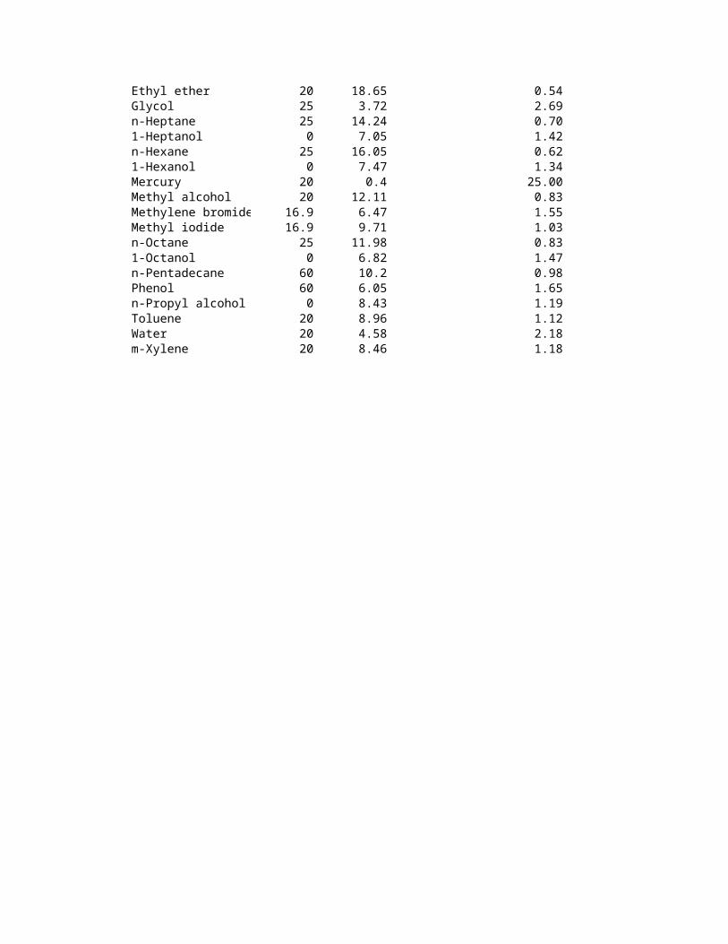
Data Source: CRC, Handbook of Chemistry and Physics, 50th Edition, 1969
Liquid Temp, C m2/dyne x 10^11 Pa lb/in2Acetic Acid 20 9.08 1.10 1.60 Acetone 20 12.75 0.78 1.13 Aniline 20 4.53 2.21 3.21 Benzene 20 9.37 1.07 1.55 Benzene, chloro 20 7.45 1.34 1.94 n-Butyl alcohol 0 8.1 1.23 1.78 Carbon disulfide 20 9.26 1.08 1.57 Carbon tetrachloride 20 10.34 0.97 1.41 Chloroform 20 9.94 1.01 1.46 Cyclohexane 25 11.1 0.90 1.31 Dodecane 60 11.3 0.88 1.28 Ethyl alcohol 20 11.19 0.89 1.29 Ethyl bromide 20 12.94 0.77 1.12 Ethylene chloride 20 8.03 1.25 1.81
Problem Statement:Calculate water hammer pressure for fast closing valve
Ethyl ether 20 18.65 0.54 0.78 Glycol 25 3.72 2.69 3.90 n-Heptane 25 14.24 0.70 1.02 1-Heptanol 0 7.05 1.42 2.06 n-Hexane 25 16.05 0.62 0.90 1-Hexanol 0 7.47 1.34 1.94 Mercury 20 0.4 25.00 36.26 Methyl alcohol 20 12.11 0.83 1.20 Methylene bromide 16.9 6.47 1.55 2.25 Methyl iodide 16.9 9.71 1.03 1.49 n-Octane 25 11.98 0.83 1.20 1-Octanol 0 6.82 1.47 2.13 n-Pentadecane 60 10.2 0.98 1.42 Phenol 60 6.05 1.65 2.39 n-Propyl alcohol 0 8.43 1.19 1.73 Toluene 20 8.96 1.12 1.62 Water 20 4.58 2.18 3.16 m-Xylene 20 8.46 1.18 1.71
lb/hin
lb/ft3lb/in2ft/s2
lb/ft2ft/s
ft/s
ft fluid
psi
sft

CENTRIFUGAL PUMP
CLIENT EQUIP. NO PAGEP-201
REV PREPARED BY DATE APPROVAL W.O. REQUISITION NO. SPECIFICATION NO.0 1 UNIT AREA PROCURED BY INSTALLED BY2
Reactor Transfer Pump
1 General2 Fluid Service Mother Liquor Pump Manufacturer TBD3 Number Required one Model Number TBD4 Pump Type ANSI AA Back Pullout Size 3x4-105 Location Indoor6 Process Data7 Fluid Pumped Water8 Normal Flow Rate gpm 360.0 Corrosive or Non-Corrosive non-corrosive9 Design Flow Rate gpm 360.0 Corrosive Compounds n/a10 Pumping Temperature deg F 86.0 Solids none11 Vapor Pressure @ P.T. psia 0.6 12 Viscosity @ P.T. cP 0.8 Hazards13 Specific Gravity @ P.T. water=1 1.0 14 Pumping Conditions15 Suction Discharge 16 Terminal Pressure psia 14.7 14.7 17 Static Head ft / psi 10.5 4.6 21.5 9.3 18 Equipment Loss (see sketch) ft / psi - - - - 19 Line Loss (per 100 equiv ft) ft / psi 6.8 2.9 30.5 13.2 20 Equiv. Line Length ft 27 15021 Safety Factor in Line Loss (%) 0% 0%22 Total friction Loss ft / psi 1.8 0.8 45.8 19.9 23 Control Valve ft / psi - - 20.0 8.7 24 Net Suction Pressure psia 18.5 25 NPSH available ft / psia 41.3 17.8 26 Total Discharge Pressure psia 52.6 27 Differential Pressure (TDH) ft / psi 79.0 34.1 28 Design Flow Rate gpm 360.0 2930 Mechanical Data31 Type Material Sketch32 Pump Head mfg std 316SS33 Impeller 9.7" diameter 316SS34 Shaft less sleeve 316SS35 Seal Single Mechanical carbon vs ceramic36 Baseplate fabricated 304SS3738 Connections Suction 1-1/2" ANSI RF Case Drn. plug39 Discharge 1" ANSI RF40 Electrical Data41 Area Classification Class 1 Group D Division 2 Enclosure TEFC42 Power Volts 460 Phases 3 Cycles 60 Frame 254T43 Horsepower Calculated 7.16 BHP 10.53 Nominal 15.0 RPM 177044 Efficiency 68%45 Notes46 Motor must be non-overloading at runout47 Fabricated baseplate sized to catch drips from pump, seal, or other components48 Provide 1-inch lip around baseplate so drips are contained49 Provide 3/4" hose bibb at low point of baseplate containment, with cap
505152
CONTROL VALVESCLIENT EQUIP. NO PAGE
REV PREPARED BY DATE APPROVAL W.O. REQUISITION NO. SPECIFICATION NO.0 175001 UNIT AREA PROCURED BY INSTALLED BY2
1
GE
NR
L Tag No. FCV-2162 Service water3 Line No./Vessel No. 2164 Line Size/Sched 3 inch, Sched 405
BO
DY
Type of Body Globe6 Body Size Port Size 3 in 3 in7 Guiding No.of Ports Cage 28 End Conn. & Rating ANSI 150# flange9 Body Material Cast Iron10 Packing Material11 Lubricator Isolat Valve12 Bonnet Type13 Trim Form Linear14 Trim Mat'l Seat/Plug15 Shaft Mat'l16 Required Seat Tightnss17 Max Allow Sound Level18
AC
TU
AT
OR
Model No. & Size19 Type of Actuator Air to close / spring20 Close at Open at21 Flow Action to open22 Fail Position open23 Handwheel & Location24
PO
SIT
.
Mfr & Model No.25 Filt Reg Gages Bypass26 Input Signal27 Output Signal28 Air Supply Pressure 95 psig29 Make & Model No.30 Input Signal31 Output Signal32
OP
TS control at 360 gpm at no greater than 85% open
3334
SE
RV
ICE
FLOW UNITS gpm35 Fluid water36 Quant Max Cv 360 12037 Quant Oper Cv 250 4838 Valve Cv Valve Fl > 14139 Norm In Press P psia 58 2640 Max Inlet Pressure > 60 psia41 Max Shutoff P psia 62 4042 Temp Max Operating 120 F 86 F43 Oper S.G. Mol. Wt. 1.00 1844 Oper Visc. % Flash 0.81 cP 045 % Superheat % Solids 0 046 Vap Press. Crit. Press psia 0.62 321047 Predicted Sound dBA48 Manufacturer49 Model No.50
TR
AN
D
UC
R