CHAPTER 13 - Rafael Landívar...
21
CHAPTER 13 Hydraulic Pumps Hydraulic pumps convert the mechanical energy transmitted by its prime mover (electric motor, internal combustion engine, etc.) into hydraulic working energy. Pumping action is the same for every pump. All pumps generate an increasing volume at the suction side and a decreasing volume at the pressure side. However, the ele- ments which perform the pumping action are not the same in all pumps. The type of pump used in an industrial hydraulic system is a positive dis- placement pump. There are many types of posi- tive displacement pumps. For this reason, we must be selective and concentrate on the most popular. These are vane, gear, and piston pumps. The first group of pumps discussed will be fixed displacement pumps. vane pumps Vane pumps generate a pumping action by caus- ing vanes to track along a ring. what a vane pump consists of A pumping mechanism of a vane pump basically consists of rotor, vanes, ring, and a port plate with kidney-shaped inlet and outlet ports. how a vane pump works The rotor of a vane pump houses the vanes and it is driven by a shaft which is connected to a prime mover. As the rotor is turned, vanes are thrown out by centrifugal force and track along a ring. (The ring does not rotate.) As the vanes make contact, a positive seal is formed between vane tip and ring . The rotor is positioned off-center to the ring. As the rotor is turned, an increasing and decreasing vol- ume is formed within the ring. Since there are no ports in the ring, a port plate is used to separate incoming fluid from outgoing fluid. The port plate fits over the ring, rotor, and vanes. The inlet port of the port plate is located Where the increasing volume is formed. The port plate's outlet port is located where the decreasing volume is generated. All fluid enters and exits the pumping mechanism through the port plate. (The inlet and outlet ports in the port plate are, of course, connected respectively to the inlet and outlet ports in the pump housing.) Inlet Port Increasing Volume Hydraulic Pump Symbol Note: Ring Ooes Not Rotate Port Plate Outlet Port 13-1
Transcript of CHAPTER 13 - Rafael Landívar...

CHAPTER 13
Hydraulic Pumps
Hydraulic pumps convert the mechanical energy transmitted by its prime mover (electric motor, internal combustion engine, etc.) into hydraulic working energy. Pumping action is the same for every pump. All pumps generate an increasing volume at the suction side and a decreasing volume at the pressure side. However, the elements which perform the pumping action are not the same in all pumps. The type of pump used in an industrial hydraulic system is a positive displacement pump. There are many types of positive displacement pumps. For this reason , we must be selective and concentrate on the most popular. These are vane, gear, and piston pumps. The first group of pumps discussed will be fixed displacement pumps.
vane pumps
Vane pumps generate a pumping action by causing vanes to track along a ring.
what a vane pump consists of
A pumping mechanism of a vane pump basically consists of rotor, vanes, ring, and a port plate with kidney-shaped inlet and outlet ports.
how a vane pump works
The rotor of a vane pump houses the vanes and it is driven by a shaft which is connected to a prime mover. As the rotor is turned, vanes are thrown out by centrifugal force and track along a ring. (The ring does not rotate.) As the vanes make contact, a positive seal is formed between vane tip and ring.
The rotor is positioned off-center to the ring. As the rotor is turned, an increasing and decreasing volume is formed within the ring .
Since there are no ports in the ring, a port plate is used to separate incoming fluid from outgoing fluid . The port plate fits over the ring, rotor, and vanes. The inlet port of the port plate is located Where the increasing volume is formed . The port plate's outlet port is located where the decreasing volume is generated. All fluid enters and exits the pumping mechanism through the port plate. (The inlet and outlet ports in the port plate are, of course, connected respectively to the inlet and outlet ports in the pump housing.)
Inlet Port
Increasing Volume
Hydraulic Pump Symbol
Note: Ring Ooes Not Rotate
Port Plate
Outlet Port
13-1

Inlet Port
Port Plate
13-2
Balanced Vane Pump
Outlet Port
Cam Ring
Catridge Assembly
balanced vane pump design
In a pump, two very different pressures are involved - working pressure of a system and lessthan-atmospheric pressure. In the vane pump which has been described, one halfofthe pumping mechanism is at less-than- atmospheric pressure. The other half is subjected to full system pressure.
PRESSURE This results in side loading the shaft which could be severe when high system pressures are encountered. To compensate for this condition , this ring is changed from circular to cam-shaped. With this arrangement, the two pressure quadrants oppose each other and the forces acting on the shaft are balanced. Shaft side loading is eliminated.
Therefore, a balanced vane pump, consists of a cam ring, rotor, vanes, and a port plate with inlet and outlet ports opposing each other. (Both inlet ports are connected together, as are the outlet ports, so that each can be served by one inlet or one outlet port in the pump housing) .
Constant volume, positive displacement vane pumps, used in industrial systems, are generally of the balanced design.
cartridge assembly
The pumping mechanism of industrial vane pumps is often an integral unit called a cartridge assembly. A cartridge assembly consists of vanes, rotor, and a cam ring sandwiched between two port plates. (Note that the port plates of the cartridge assembly are somewhat different in design than the port plates previously illustrated).
An advantage of using a cartridge assembly is easy pump servicing. After a period of time when pump parts naturally wear, the pumping mechanism can be easily removed and replaced with a new cartridge assembly. Also, if for some reason the pump's volume must be increased or decreased, a cartridge assembly with the same outside dimension, but with the appropriate volume, can be quickly substituted for the original pumping mechanism.
vane loading
Before a vane pump can operate properly, a positive seal must exist between vane tip and cam ring . When a vane pump is started, centrifugal force is relied on to throw-out the vanes and achieve a seal.

(This is the reason that the minimum operating speed for most vane pumps is 600 rpm) .
Once the pump is primed and system pressure begins to rise, a tighter seal must exist at the vane so that leakage does not increase across the vane tip. To generate a better seal at high pressures, industrial vane pumps direct system pressure to the underside of the vane. With this arrangement, the higher system pressure becomes, the more force is developed to push the vane out against the cam ring.
Hydraulically loading a vane in this manner develops a very tight seal at the vane tip. But, if the force loading the vane is too great, vanes and cam ring would wear excessively and the vanes would be a source of drag.
As a compromise between achieving the best seal and causing the least drag and wear, manufacturers design their pumps so that the vanes are only partially loaded.
The use of vanes with a chamfer or beveled edge is one way in which high vane loading is eliminated. With these vanes, the complete underside vane area is exposed to system pressure as well as a large portion of the area at the top of the vane. This results in a balance of most of the vane. The pressure which acts on the unbalanced area is the force which loads the vane.
In high pressure systems, the use of a vane with a beveled edge still results in too much wear and too much drag. The use of this type vane in a high pressure pump is not satisfactory. Another arrangement is used.
Common vane construction of high pressure vane pumps consists of dual vanes, intra-vanes, springloaded vanes, pin-vanes, and angled vanes. The dual vane construction consists of two vanes in each vane slot. Each vane is almost completely balanced. And , a good seal is achieved because two vanes are used.
The intra-vane is another type of vane construction which consists of a small vane within a large vane with a beveled edge. System pressure is directed to the area above the small vane. This again results in less vane loading.
Very similar to the intra-vane construction is the pin-vane construction. In pin-vane construction pressure is directed to the underside of a pin. The pin then forces the vane out against the cam ring.
Intra-Vane
Force and Seal Generated Here
Dual Vane
Intra-Vane
Vane rr=:;;;==:::::;:?\
Pin
Pin-Vane
13-3

Spring-Loaded Von.
13-4
Angled Vane
Variable Volume. Pressure Compensated
Pump Symbol
System Pressure
With a spring-loaded vane, spring pressure at the ~
bottom of the vane is primarily what loads th.e vane.
Another means of reducing vane loading is positioning the vanes in the rotor at an angle. This results in a slight loading of the vane without using any other mechanical device.
double pumps
The vane pump which has been described is referred to as a single pump; that is, it consists of one inlet, one outlet and a single cartridge assembly. Vane pumps are also available as a double pump.
A double vane pump consists of housing with two cartridge assemblies, one or two inlets, and two separate outlets. In other words, a double pump consists of two pumps in one housing. A double pump can discharge two different flow rates from each outlet. Since both pump cartridges are connected to a common shaft, one prime mover is used to drive the whole unit.
Double pumps are many times used in hi-Io circuits and where two different flow rates are supplied from the same power unit.
Double pumps give up to twice the flow of a single pump without an appreciably larger unit.
case drain
All variable volume, pressure compensated pumps must have their housings externally drained. The pumping mechanisms in these pumps move extremely fast when pressure compensation is required . Any buildup of fluid within the housing would hinder their movement.
Also , any leakage which accumulates in a pump housing is generally directed back to the pump's inlet side. The leakage from a variable volume pump, while it is compensating , is generally hot. If it were diverted to the inlet side, the fluid would get progressively hotter. Externally draining the housing alleviates the problem.
The external drain of a pump housing is commonly referred to as a case drain .
gear pumps
Gear pumps generate a pumping action by causing gears to mesh and unmesh .

what a gear pump consists of
A gear pump basically consists of a housing with inlet and outlet ports, and a pumping mechanism made up of two gears. One gear, the drive gear, is attached to a shaft which is connected to a prime mover. The other gear is the driven gear.
how a gear pump works
As the drive gear is turned by a prime mover, it meshes with and rotates the drive gear. The action of teeth meshing and unmeshing generates an increasing and decreasing volume. At the inlet where gear teeth unmesh (increasing volume) , fluid enters the housing. The fluid is then trapped between the gear teeth and housing, and carried to the other side of the gear.
At this point, the gear teeth mesh (decreasing volume) and force the fluid out into the system.
A positive seal in this type pump is achieved between the teeth and the housing , and between the meshing teeth themselves .
Gear pumps are generally an unbalanced design .
external gear pumps
The gear pump that has been described above is an external gear pump; that is, both meshing gears have teeth on their outer circumferences. These pumps are sometimes referred to as gear-an-gear pumps.
There are basically three types of gears used in external gear pumps - spur, helical , and herringbone. Since the spur gear is the easiest to manufacture, this type pump is the most common and the least expensive of the three.
internal gear pump
An internal gear pump consists of one external gear which meshes with the teeth on the inside circumference of a larger gear. This type pump is sometimes referred to as gear-with in-gear pump. The most common type of internal gear pump in industrial systems is the gerotor pump.
gerotor pump
A gerotor pump is an internal gear pump with an inner drive gear and an outer drive gear. The inner gear has one less tooth than the outer gear.
Inlet
Gear Teeth Unmesh
Gear Pump
Helical Gear
Herringbone Gear
Driven Gear
Outlet
Shaft Connected To Prime
Mover
Outlet
Spur Gear
13-5

13-6
Port Plate
Outlet Port
Cylinder Shaft Port
irre l~Hole Plate
; ~o (I{) o~
Piston Inlet Outlet Bore Port Port
Axial Piston Pump
Piston Shoe
Cylinder Barrel
As the inner gear is turned by a prime mover, it rotates the larger outer gear. On one side of the pumping mechanism, an increasing volume is formed as gear teeth unmesh. On the other half of the pump, a decreasing volume is formed. A gerotor pump has an unbalanced design.
Fluid entering the pumping mechanism is separated from the discharge fluid by means of a port plate as in a vane pump.
While fluid is carried from inlet to outlet, a positive seal is maintained as the inner gear teeth follow the contour of crests and valleys of the outer gear.
piston pumps
Piston pumps generate a pumping action by causing pistons to reciprocate within a piston bore.
what a piston pump consists of
The pumping mechanism of a piston pump basically consists of a cylinder barrel ; pistons with shoes; swash plate ; shoeplate ; shoeplate bias spring ; and port plate.
how a piston pump works
Earlier, we have seen one example of a piston pump. This pump generates an increasing and decreasing volume by means of a plunger being pulled and pushed in and out of a cylinder body. It was pointed out that the disadvantages ofthis type of pump were that the pump developed a pulsating flow and that it could not be easily operated by an electric motor or internal combustion engine.
However, a piston can be made to reciprocate easily by the turning motion of a prime mover as well as developing a smooth flow.
In the example illustrated , a cylinder barrel with one piston bore is fitted with one piston. A swashplate is positioned at an angle . The shoe of the piston rides on the surface of the swash plate.
As the cylinder barrel is rotated , the piston shoe follows the surface of the swashplate . (The swashplate does not rotate.) Since the swashplate is at an angle, this results in the piston reciprocating within the bore. In one half of the circle of rotation, the piston moves out of the cylinder barrel and generates an increasing volume.
In the other half of the circle of rotation , this piston moves into the cylinder barrel and generates a

decreasing volume. In actual practice, the cylinder barrel is fitted with many pistons. The shoes of the pistons are forced against the swashplate surface by ashoeplate and bias spring. To separate the incomipg fluid from the discharge fluid, a port plate is [positioned at the end of the cylinder barrel opposite ,the swashplate .
~ shaft is attached to the cylinder barrel which connects it with the prime mover. This shaft can be located at the end of the barrel where the porting is taking place. Or, more commonly , it can be positioned at the swashplate end. In this case, the swash plate and shoeplate have a hole in their centers to accept the shaft. If the shaft is positioned at the other end , just the port plate has a shaft hole.
The piston pump which has been described above is known as an axial or in-line piston pump; that is , the pistons are rotated about the same axis as the pump shaft.
Axial piston pumps are the most popular piston pumps in industrial applications. Other types of piston pumps include the bent-axis and radial piston pumps.
bent-axis piston pump
The pumping mechanism of a bent-axis piston pump consists of a cylinder barrel , pistons, port plate , flange , piston linkages, and a drive shaft. In this pump the cylinder barrel is not in-line with the drive shaft, but is at an angle to the shaft. Because of this arrangement, as the shaft is turned the pistons are pulled out of the barrel during one half of the barrel rotation. This generates an increasing volume. On the other half of the barrel rotation , the pistons are pushed in and a decreasing volume is formed. In this pump, incoming fluid is separated from discharge fluid by means of a port plate .
radial piston pump
The pumping mechanism of a radial piston pump baSically consists of a cylinder barrel , pistons with shoes, a ring, and a valve block .
The action of a radial piston pump is quite similar to a vane pump. But, instead of using vanes to track along a ring , the pump uses pistons.
The cylinder barrel , which houses the pistons, is Positioned off-center to the ring. As the cylinder barrel is rotated , an increasing volume is formed within the cylinder barrel during one half of the barrel rotation. During the other half, a decreasing volume is formed .
Cylinder Barrel
Inlet
Piston
Piston
Bent-Axis Piston Pul1l'
Shaft
Valve Block
Outlet
Piston Shoe
Radial Piston Pump
13-7

13-8
Variable Volume Pump Symbol
Fluid enters and is discharged from the pump through the valve block in the center of the pump.
variable volume vane pumps
A positive displacement vane pump delivers the same volume of fluid for each revolution. Industrial pumps are generally operated at 1200 or 1800 rpm. This infers that the pump flow rate remains constant.
In some cases, it is desirable that a pump's flow rate be variable. One way of accomplishing this is by varying the speed of the prime mover. This is usually economically impractical. The only other way, then, to vary the output of a pump is to change its displacement.
The amount of fluid which a vane pump displaces is determined by the difference between the maximum and minimum distance the vanes are extended and the width ofthe vanes. While the pump is operating , nothing can be done to change the width of a vane. But, a vane pump can be designed so that the distance the vanes are extended can be changed. This is known as a variable volume vane pump.
regulating hydraulic power with variable volume pumps
Since hydraulic power consists of gpm (Ipm) and psi (bar) , power generation by pump/electric motor can be controlled by reducing the generation of flow as well as limiting pressure. This is accomplished with the use of variable volume vane and piston pumps which are pressure compensated. These pumps have the ability to reduce their displacement once system pressure reaches a certain level.
The intent of this lesson is to describe how pressure compensated, variable volume pumps can more easily match hydraulic power generated with mechanical power output and how wear affects their operation.
To begin the lesson, we look at the operation of variable volume vane and piston pumps.
what a variable volume vane pump consists of
The pumping mechanism of a variable volume vane pump basically consists of a rotor, vanes, a cam ring which is free to move from side to side, a port plate, a thrust bearing to guide the cam ring,
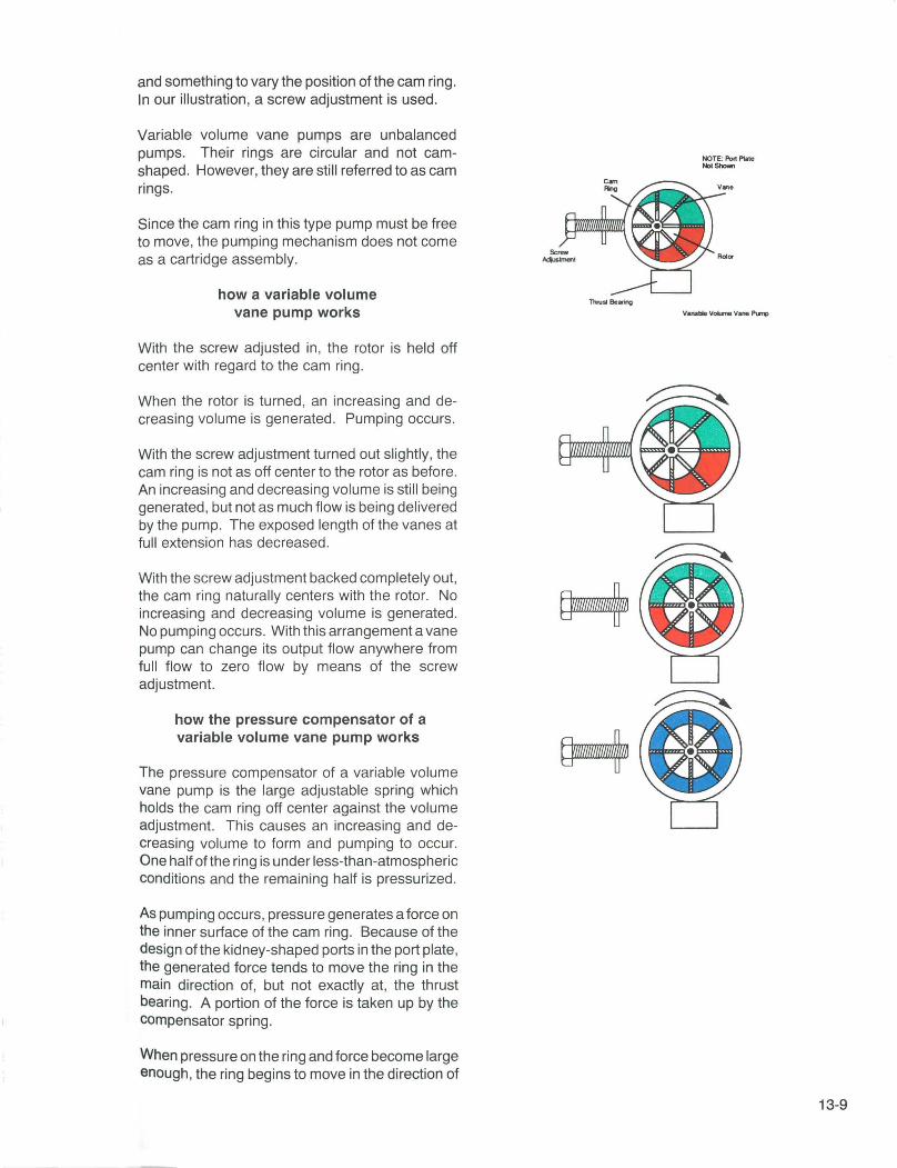
and something to vary the position of the cam ring . In our illustration, a screw adjustment is used.
Variable volume vane pumps are unbalanced pumps. Their rings are circular and not camshaped. However, they are still referred to as cam rings.
Since the cam ring in this type pump must be free to move, the pumping mechanism does not come as a cartridge assembly.
how a variable volume vane pump works
With the screw adjusted in, the rotor is held off center with regard to the cam ring .
When the rotor is turned, an increasing and decreasing volume is generated. Pumping occurs.
With the screw adjustment turned out slightly, the cam ring is not as off center to the rotor as before. An increasing and decreasing volume is still being generated, but not as much flow is being delivered by the pump. The exposed length of the vanes at full extension has decreased .
With the screw adjustment backed completely out, the cam ring naturally centers with the rotor. No increasing and decreasing volume is generated. No pumping occurs. With this arrangement a vane pump can change its output flow anywhere from full flow to zero flow by means of the screw adjustment.
how the pressure compensator of a variable volume vane pump works
The pressure compensator of a variable volume vane pump is the large adjustable spring which holds the cam ring off center against the volume adjustment. Th is causes an increasing and decreasing volume to form and pumping to occur. One half ofthe ring is under less-than-atmospheric conditions and the remaining half is pressurized .
As pumping occurs , pressure generates a force on the inner surface of the cam ring . Because of the design of the kidney-shaped ports in the port plate, the generated force tends to move the ring in the main direction of, but not exactly at, the thrust bearing. A portion of the force is taken up by the compensator spring.
When pressure on the ring and force become large enough, the ring begins to move in the direction of
ThrullBooring
NOTE; Port Plale ""'Show!
13-9

Pump Compensating
13-10
Thrust Bearing
the spring reducing discharge flow. The ring cannot move through the thrust bearing because it is a mechanical stop. Once the ring centers witH the rotor, it stops and discharge flow ceases. The cam ring will not cross to the other side of the rotor because this would cause the pressure half of the pumping mechanism to form an increasing volume which is suction operated. Pressure would immediately drop resulting in the spring pushing the ring off center once again.
The more the pressure compensator adjustment is screwed in , the more the compensator spring is compressed and the greater the force holding the ring off center. To protect the pump from too high of a pressure adjustment, pressure compensated vane pumps are commonly equipped with over pressure stops.
In the next section, the operation of a variable volume axial piston pump is described. We find that the compensator in this pump basically functions as a pilot operated relief valve .
vane pump dual compensation
In a vane pump, a dual compensator consists of a solenoid valve, pilot valve , and orifice which senses system pressure.
With the solenoid valve closed , fluid pressure is allowed to accumulate in the spring chamber through the sensing orifice. This adds to the spring pressure biasing the cam ring against the volume adjustment. The maximum amount of fluid pressure is determined by the pilot valve setting. Compensator setting is a function of spring and fluid pressure.
If the spring were adjusted for 600 psi (41.4 bar) and the pilot valve were adjusted for 900 psi (62 bar), the compensator setting would be 1500 psi (103.4 bar) .
A second compensator setting is achieved when the solenoid valve is energized . This action vents the spring chamber of fluid pressure. Spring pressure only holds the cam ring against the volume adjustment. Since this has a value of 600 psi (41.4 bar) in this example, the pump now compensates at 600 psi (41 .4 bar).
variable volume from a gear pump
The output volume of a gear pump is determined by the volume of fluid each gear displaces, and by the rpmat which the gears are turning. Conse-

quently, the output volume of gear pumps can be altered by replacing the original gears with gears of different dimensions or by varying rpm.
Gear pumps, whether of the internal or external variety, do not lend themselves to a change in displacement while they are operating. There is nothing that can be done to vary the physical dimensions of a gear while it is turning .
One practical way, then, to vary the output flow from a gear pump is to vary the speed of its prime mover. This can be easily done when the pump is being driven by a variable speed internal combustion engine. It can also be accomplished electrically by using a variable speed electric motor.
variable volume axial piston pump
The amount of fluid which an axial piston pump displaces per revolution is determined by the cross sectional area of the piston and the distance pistons are stroked within their cylinder bores. While pumping takes place, nothing can be done to change the cross sectional area of the pistons. But, a variable volume axial piston pump is designed so that the distance pistons are stroked can be varied.
what a variable volume axial piston pump consists of
The pumping mechanism of a variable volume axial piston pump baSically consists of a barrel , port plate , pistons with shoes, an adjustable swashplate, shoeplate , maximum volume adjustment, control piston, orifice, compensator spool , pilot valve, and various bias springs.
Pistons are housed in the bores of the barrel. Attached to the barrel is a shaft which is coupled to an electric motor. The shaft can be connected at either the port plate or swashplate side.
how the volume adjustment of a variable volume axial piston
pump works
The volume adjustment of a variable volume axial piston pump is a threaded rod which mechanically limits the swash plate angle.
With the volume adjustment backed completely out, the spring biasing the control piston positions the swashplate at an extreme angle. As the barrel is rotated by a prime mover, piston shoes are forced by mechanical bias to contact the swash-
Port Swashplate Piston Barrel Plate
Pressure Compensator Adjust.
Drain
Oudet
Orifice
Compensator Spool
13-11
Volume Adjustment
Out
13-12
Volume Adjustment
In ~::r:=~~.~ Less Flow
Overcenter Axial Piston Pump (Drive Shaft Not Shown)
Swash plate Centered
Swashplate Ang le
\
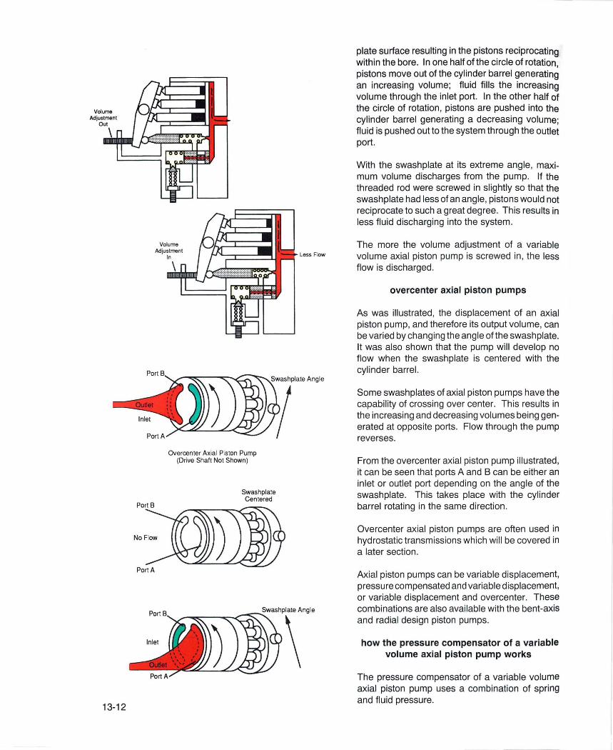
plate surface resulting in the pistons reciprocating within the bore. In one half of the circle of rotation, pistons move out of the cylinder barrel generating an increasing volume; fluid fills the increasing volume through the inlet port. In the other half of the circle of rotation , pistons are pushed into the cylinder barrel generating a decreasing volume; fluid is pushed out to the system through the outlet port.
With the swashplate at its extreme angle, maximum volume discharges from the pump. If the threaded rod were screwed in slightly so that the swashplate had less of an angle, pistons would not reciprocate to such a great degree. This results in less fluid discharging into the system.
The more the volume adjustment of a variable volume axial piston pump is screwed in , the less flow is discharged.
overcenter axial piston pumps
As was illustrated, the displacement of an axial piston pump, and therefore its output volume, can be varied by changing the angle ofthe swashplate. It was also shown that the pump will develop no flow when the swash plate is centered with the cylinder barrel.
Some swash plates of axial piston pumps have the capability of crossing over center. This results in the increasing and decreasing volumes being generated at opposite ports. Flow through the pump reverses.
From the overcenter axial piston pump illustrated, it can be seen that ports A and B can be either an inlet or outlet port depending on the angle of the swashplate. This takes place with the cylinder barrel rotating in the same direction.
Overcenter axial piston pumps are often used in hydrostatic transmissions wh ich will be covered in a later section .
Axial piston pumps can be variable displacement, pressure compensated and variable displacement, or variable displacement and overcenter. These combinations are also available with the bent-axis and radial design piston pumps.
how the pressure compensator of a variable volume axial piston pump works
The pressure compensator of a variable volume axial piston pump uses a combination of spring and flu id pressure.

In the pressure compensated vane pump seen previously, a single spring acted as the compensator. This was possible because the force moving the ring did not act directly opposite the spring, but at an angle. Most of the force was taken up by the thrust bearing. In a pressure compensated axial piston pump, this is not the case.
As a pressure compensated axial piston pump is operating, pressure acts on the ends of the pistons doing the pumping. With the centerline of the swash plate trunnion offset from the centerline of the barrel, the pistons under pressure attempt to push the swashplate to an upright position. This force can be considerable and is counteracted directly by spring and fluid pressure acting on the control piston.
A pressure compensator of a typical axial piston pump consists of a control piston, compensator spool, adjustable pilot valve, and bias springs. When pressure at pump outlet is high enough to overcome the setti ng of the pilot valve and the bias springs, the swash plate is pushed back to an upright position by the pressurized pistons.
Once the swashplate achieves a zero angle, it stops. The swash plate cannot be pushed to the other side of center since this would cause the pressure half of the pumping mechanism to form an increasing volume which is suction operation. Pressure would immediately drop resulting in the spring offsetting the swash plate once again.
The adjustable pilot valve, compensator spool and its bias spring are very similar in operation to a pilot operated relief valve. Pump discharge pressure is sensed through an orifice in the compensator spool. It is allowed to accumulate in the bias spring chamber of the spool and the amount of accumulated pressure is limited by the pilot valve. When pressure at the end of the compensator spool is sufficient to overcome the pilot valve setting and the bias spring, the compensator spool will move venting the control piston spring chamber.
Assume that the spring biasing the compensator spool has a value of 100 psi (6.9 bar) and that the pilot valve will limit pilot pressure in the spring chamber to 700 psi (48.3 bar).
With a system pressure of 500 psi (34.5 bar), 500 psi (34.5 bar) acts to push the spool to the left. 500 psi (34.5 bar) is transmitted through the orifice to the spring chamber acting to hold the spool in place. Areas exposed to pressure on either side of
Trunnion Centerline
Control Piston
Pilot Valve
Set for 700 i 48.3 bar
Control Piston Cavity
Orifice
Compensator Spool
500 psi 34.5 bar
13-13
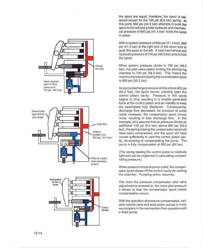
Valve cracked open limiting pressure to 700 psi 148.3 bar
Swash plate approaches zero angle
13-14
Swash plate at Zero Angle
700 psi 48.3 bar
Slightly greater than 800 psi 1 55.2 bar
Pistons cracks open passage to tank
Cavity Vented
the spool are equal; therefore, the spool is balanced except for the 100 psi (6.9 bar) spring. At this point, 500 psi (34.5 bar) attempts to push the spool to the left and a total hydraulic and mechanical pressure of 600 psi (41.4 bar) holds the spool in place.
With a system pressure of 600 psi (41.4 bar) , 600 psi (41.4 bar) at the right end of the spool acts to push the spool to the left. A total mechanical and hydraulic pressure of 700 psi (48.3 bar) acts to hold the spool.
When system pressure climbs to 700 psi (48.3 bar), the pilot valve opens limiting the pilot/spring chamber to 700 psi (48.3 bar) . This means the maximum pressure biasing the compensator spool is 800 psi (55.2 bar).
As pump discharge pressure climbs above 800 psi (55.2 bar), the spool moves cracking open the control piston cavity. Pressure in this cavity begins to drop resulting in a smaller generated force at the control piston and an inability to keep the swashplate fully displaced. Consequently, discharge flow decreases. As pressure at pump outlet increases, the compensator spool moves more, resulting in less discharge flow. In this example, let's assume that as pressure climbs an additional 100 psi (6.9 bar) above 800 psi (55.2 bar) , the spring biasing the compensator spool will have been compressed, and the spool will have moved sufficiently to vent the control piston cavity, de-stroking or compensating the pump. The pump is fully compensated at 900 psi (62 bar).
(The spring biasing the control piston is relatively light and can be neglected in calculating compensating pressure.)
When pressure drops at pump outlet, the compensator spool closes off the control cavity de-venting the chamber. Pumping action resumes.
The more the pressure compensator pilot valve adjustment is screwed in, the more pilot pressure it allows to bias the compensator spool before compensation occurs.
With the operation of pressure compensated, variable volume vane and axial piston pumps in mind, we compare in the next section their operation with a fixed pump.
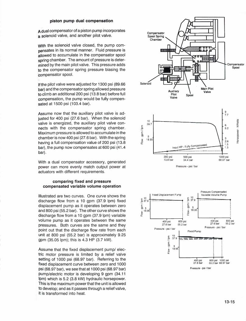
piston pump dual compensation
A dual compensator of a piston pump incorporates a solenoid valve, and another pilot valve.
With the solenoid valve closed, the pump compensates in its normal manner. Fluid pressure is allowed to accumulate in the compensator spool spring chamber. The amount of pressure is determined by the main pilot valve. This pressure adds to the compensator spring pressure biasing the compensator spool.
Ifthe pilot valve were adjusted for 1300 psi (89.66 bar) and the compensator spring allowed pressure to climb an additional 200 psi (13.8 bar) before full compensation , the pump would be fully compensated at 1500 psi (103.4 bar) .
Assume now that the auxiliary pilot valve is adjusted for 400 psi (27.6 bar) . When the solenoid valve is energized , the auxiliary pilot valve connects with the compensator spring chamber. Maximum pressure is allowed to accumulate in the chamber is now 400 psi (27.6 bar) . With the spring having a full compensation value of 200 psi (13.8 bar) , the pump now compensates at 600 psi (41.4 bar) .
With a dual compensator accessory, generated power can more evenly match output power at actuators with different requirements .
comparing fixed and pressure compensated variable volume operation
Illustrated are two curves. One curve shows the discharge flow from a 10 gpm (37.9 Ipm) fixed displacement pump as it operates between zero and 800 psi (55.2 bar) . The other curve shows the discharge flow from a 10 gpm (37.9 Ipm) variable volume pump as it operates between the same pressures. Both curves are the same and they point out that the discharge flow rate from each unit at 800 psi (55.2 bar) is approximately 9.25 gpm (35.05 Ipm) ; this is 4.3 HP (3.7 kW) .
Assume that the fixed displacement pump/ electric motor pressure is limited by a relief valve setting of 1000 psi (68.97 bar). Referring to the fixed displacement curve between zero and 1000 psi (68.97 bar) , we see that at 1000 psi (68.97 bar) pump/electric motor is developing 9 gpm (34.11 Ipm) which is 5.2 (3 .8 kW) hydraulic horsepower. This is the maximum power that the unit is allowed to develop; and as it passes through a relief valve, it is transformed into heat.
10 39.7
E .9--E a. OJ 5 ;: 18.95 0 u:
Input HP - Fully compensated
200 psi 500 psi 13.8 bar 34.4 bar
Pressure - psi I bar
Compensator Spool
9 7 .7
6 5.2
3 2.6 1.5 1.3
1000 psi 68.97 bar
a Q)
f'! o I
Fixed Displacement Pump Pressure Compensated Variable Volume Pump
11~9'+-:-· - :-::-- .::-:- --::'- .""'-- -~--=--=, -"",,--E g; 5 ~ 18.95 o u:
400 psi 800 psi 27.6 bar 55.2 bar
Pressure - psi I bar
E 10 .9- 37.9
E a. 0> 5 ;: 18.95 0 u:
E 10 .Q- 37.9 •• ••• ..•••• ••••• •• -E g; 5 ~ 18.95 o u:
Fixed Pump
400 psi 800 psi 27.6 bar 55.2 bar
Pressure - psi I bar
400 psi 800 psi 1000 psi 27.6 bar 55.2 bar 68.97 bar
Pressure - psi I bar
13-15

E .Q.
E a. m , ~ u::
10
Pressure Compensated Variable Volume Pump
37 .9 t .. -:: .. 7: •. 7: .. ~ .. ~ .. :-:-: .. :-:-: .• :":': •. ~ .• :... . ....... _L 8
55.2
4.2 HP /3 .1 kW
5 18.95
400 psi 27 .6 bar
2.2 HP / 1.6 kW
o HP / 0 kW
800 psi 1000 psi 55.2 bar 68 .97 bar
Pressure - psi / bar
Constant Volume, Rapid Advance and Feed Circuit
13-16
Pressure compensated vane pumps are characteristically fully compensated within 200 psi (13.8 bar). Piston pumps compensate fully within 100 psi (6.9 bar) or less. Since a vane pump has a wider compensating band, the curves of pressure compensated, variable volume vane pumps will be shown. This will more easily illustrate a pump's operating characteristic during compensation.
Assume now that the pressure compensated variable volume pump has a compensator setting of 1000 psi (68.97 bar) . Referring to the pressure compensated pump curve between zero and 1000 psi (68.97 bar), we find that at 800 psi (55.2 bar) and 9.25 gpm (34.86 Ipm) (4.3 hp/3.7 kW), discharge flow begins to decrease. Consequently, generated power decreases as system pressure approaches 1000 psi (68.97 bar) . At a pressure of 900 psi (62.1 bar) discharge flow is 8 gpm (30.3 Ipm) (4.2 HP/3.1 kW). At 950 psi (67.85 bar), discharge flow is 4 gpm (15.16 Ipm) (2.2 HP/1.6 kW). At 1000 psi (68.97 bar), discharge flow rate is zero gpm (0 hp).
With a pressure compensated pump coupled to a prime mover, generated hydraulic power is not only controlled by limiting pressure, but it is reduced by regulating discharge flow. This means less heat is generated in a system since generated power is not wasted over a relief valve.
We have seen that when a pressure compensated pump is fully compensated, the generated hydraulic power to the system is zero. However, the prime mover coupled to the pump must still develop power because of internal leakage and mechanical inefficiencies of the pump.
hydraulic pumps in a circuit
The systems which have been described to this point were primarily constant volume systems. In these systems, the pump would apply whatever pressure was required to get its full flow out into the system.
In the circuit illustrated, the 50 gpm (189.5 Ipm) pump delivers its flow to the work cylinder to achieve a rapid advance. When the cylinder rod reaches the limit switch, the solenoid of the twoway valve is energized and the cylinder rod goes into a feed rate. At this point, the pump is delivering to the system 43.7 HP (32.6 kW) (50 gpm x 1500 psi x .000583). If a hi-Io system were used in the same system, less horsepower would be used.

Let us assume that the feed rate required is 3.7 gpm (14.02 Ipm) . With a hi-Io system, we could use a 45 gpm (170.6Ipm) pump and 5 gpm (1 8.95 Ipm) pump to achieve the rapid advance. During the feed rate , the 45 gpm (170.6 Ipm) is dumped to tank through the unloading valve . The 5 gpm (18.95 Ipm) pump develops the required flow for the feed rate . At this point, 4.4 hp (3 .3 kW) is delivered to the system. (5 gpm x 1500 psi x .000583) .
A pressure compensated , variable volume pump can make the system even more efficient. With this type pump, the relief valve is eliminated. When the cylinder goes into its feed rate, the compensator only allows the pump to deliver 3.7 gpm (14.02 Ipm) at 1500 psi (103.4 bar). This is equal to 3.2 HP (2 .3 kW) .
Systems which use pressure compensated , variable volume pumps are quite efficient.
standby pressure
It was illustrated earlier that pressure compensated pumps mayor may not be compensated during machine idle time. This was due to the input power requirements at various compensator settings .
From the illustrated curve , it can be seen that input power is quite low when the pump is compensating at 200 psi (13.8 bar) approximately .5 horsepower (.37 kW) as compared to compensating at 1 000 psi (68.97 bar) where the input is 1.5 horsepower (1 .1 kW) . This can be taken advantage of during machine idle time.
A pressure compensated vane pump is illustrated. The pump is equipped with a dual compensator.
Assume that the spring is adjusted for 200 psi (13.8 bar) and the pilot valve is adjusted for 800 psi (55 .2 bar). The pump will be fully compensated at 1000 psi (68 .97 bar).
When the solenoid valve is energized during machine idle, the spring chamber is vented compensating the pump at 200 psi (13.8 bar) . The pump stands by at this pressure until the work cycle resumes.
A pressure compensated piston pump is also illustrated. This unit is equipped with a solenoid valve .
E 10 .9- 39.7 -E Q. 5 Ol
:;: 18.95 0 u::
~ Limit U switch
Hi-La System
Pressure Compensated System
9 HP 1 7.7 kW
6 HP 15 .2 kW
3 HP 1 2 .6 kW
L:==~~ .. = ... = ... : ... = ... = ... = ... = ... = ... : .. : ... ~ ... ~ ... ~ ... ~1 . 5 HP / 1 3 kW 200 psi 500 psi
13.6 bar 34.4 bar
Pressure - psi 1 bar
1000 psi 68.7 bar

10 39.7
E .9--E a. 0>
5 ~ 18.95 0 u::
13-18
1.5 Constant Horsepower 1.1 Constant kW
Normal curve
":.:.- .......... >~~~·I·~~~·;t~·~t··· .. 1 •••• 1.5hp / 1.1 kW ~.
/.... .... Actual performance '. •••••• '. 15 hp / 1.1 kW ••••••
500 psi 34.4 bar
Pressure· psi Ibar
Constant HP Spmg
o 0\0 00 0
....
1000 psi 68.97 bar
Assume the compensator spool spring has a value of 200 psi (13.8 bar) at full compensation . The pilot valve is adjusted for 800 psi (55.2 bar). The pump will be fully compensated at 1000 psi (68.97 bar).
During machine idle, the solenoid valve is energized venting the compensator spool spring chamber. The pump compensates at 200 psi (13.8 bar) and stands by until work is required.
By causing a pressure compensated pump to compensate at a low pressure during idle time, minimum power is used .
horsepower limiting
Many variable volume, vane and piston pumps have a horsepower limiting option. This enables a pump/electric motor not to exceed a given horsepower regardless of load resistance .
Horsepower is work performed at a rate of 550 ft.lb ./sec (746 W) . A 775 lb. loading moving 1 ft. in 1 second is 1.5 (1.1 kW) horsepower. Likewise a 1550 lb. load moving 1 ft . in 2 seconds, or a 2325 lb. load moving 1 ft. in 3 seconds, is 1.5 (1.1 kW) horsepower.
Consequently, an electric motor coupled to a variable volume pump with a horsepower limiting option could move a 775 lb. (3441 N) , 1550 lb. (6882 N), and 2325 lb. (10323 N) load using the same horsepower (kW). With a fixed displacement or ordinary pressure compensated unit, this is notthe case; horsepowerwould increase as load resistance increased . (This assumes the pressure compensated pump is not compensating.) A horsepower limiting option is achieved in a vane pump by using a compensator spring with certain compression characteristics. As the cam ring moves closer to rotor center, spring pressure increases and flow decreases. In this manner horsepower is kept relatively constant.
In a piston pump, constant horsepower is achieved with the addition of a pilot valve and control piston of a specific contour. As swashplate approaches a zero angle, the control piston contour increases the pilot setting of the valve . Compensator pressure increases as flow decreases keeping horsepower relatively constant. Since actuator speed decreases as load increases, a constant horsepower feature is found in applications where electric motor size is more important than cycle time. Examples of such systems would be commercial garbage compactors and lift trucks.

volumetric efficiency
While turning at a constant rpm, we generally think of a positive displacement pump as delivering a constant rate of flow regardless of system pressure. This is not entirely true. As system pressure increases, the internal leakage of various pumping mechanisms increase. This results in a decreased output flow. The degree to which this happens is known as volumetric efficiency.
The expression which describes volumetric efficiency is:
Volumetric Efficiency = Actual Output x 100 (%) Theoretical Output
For example, if a particular pump had a theoretical output at 1200 rpm of 10 gpm (37.9 Ipm), but the actual delivery at 1000 psi (68.97 bar) were 9 gpm (34.1 Ipm), the volumetric efficiency would be 90%.
Typically, piston pumps have an initial volumetric efficiency in the high 90's. Gear and vane equipment range from the high 80's to the mid 90's in volumetric efficiency.
overall efficiency
The overall efficiency of a hydraulic pump takes into account a pump's mechanical efficiency as well as its volumetric efficiency. This can be determined by dividing the hydraulic horsepower delivered to the system by the pump, by the input horsepower of its prime mover. An expression which describes overall efficiency is:
Overall Efficiency = Hydraulic HP Output x 100 (%) Input HP of Prime Mover
For instance, if a particular pump delivered 10 gpm (37 .9Ipm) to a system at 1 000 psi (68.97 bar) , this would equal 5.8 hp (4.3 kW) (hp = gpm x psi x .000583) .
If an electric motor driving the pump had to develop 7 hp (5.2 kW) , then the overall efficiency would be 83%.
The overall efficiencies of industrial hydraulic gear, vane, and piston pumps operating at a 1000 psi (68.97 bar) is approximately 85%. Conversely, the overall efficiencies of these same pumps at 200 psi (13.8 bar) is about 60-70%.
1)-c Q) '0 :e w
::E c.. C!l
I ~ u::
Pump Volumetric Efficiency
Pressure - PSI
Pump Overall Efficiency
Pressure - PSI
13-19

13-20
Industrial hydraulic pumps are generally designed to operate at pressures above 200 psi (13.8 bar). For this reason, the overall efficiency of a pump is diminished at this low pressure.
terms and idioms associated with hydraulic pumps
COMBINATION PUMP - a double pump which is equipped with accessory valving to perform relief and unloading functions.
SLiPPAG E- internal leakage of a pumping mechanism.
TWO-STAGE PUMP - a pump with two pumping mechanisms (stages) . The units are connected in series; that is, one feeds the other. With this arrangement, two pumping mechanisms rated at 1000 psi (68.97 bar) individually, could be used to a maximum pressure of 2000 psi (137.9 bar) . Twostage pumps were popular in the days of hydraulics when high pressure pumps were not available.
exercise hydraulic pumps
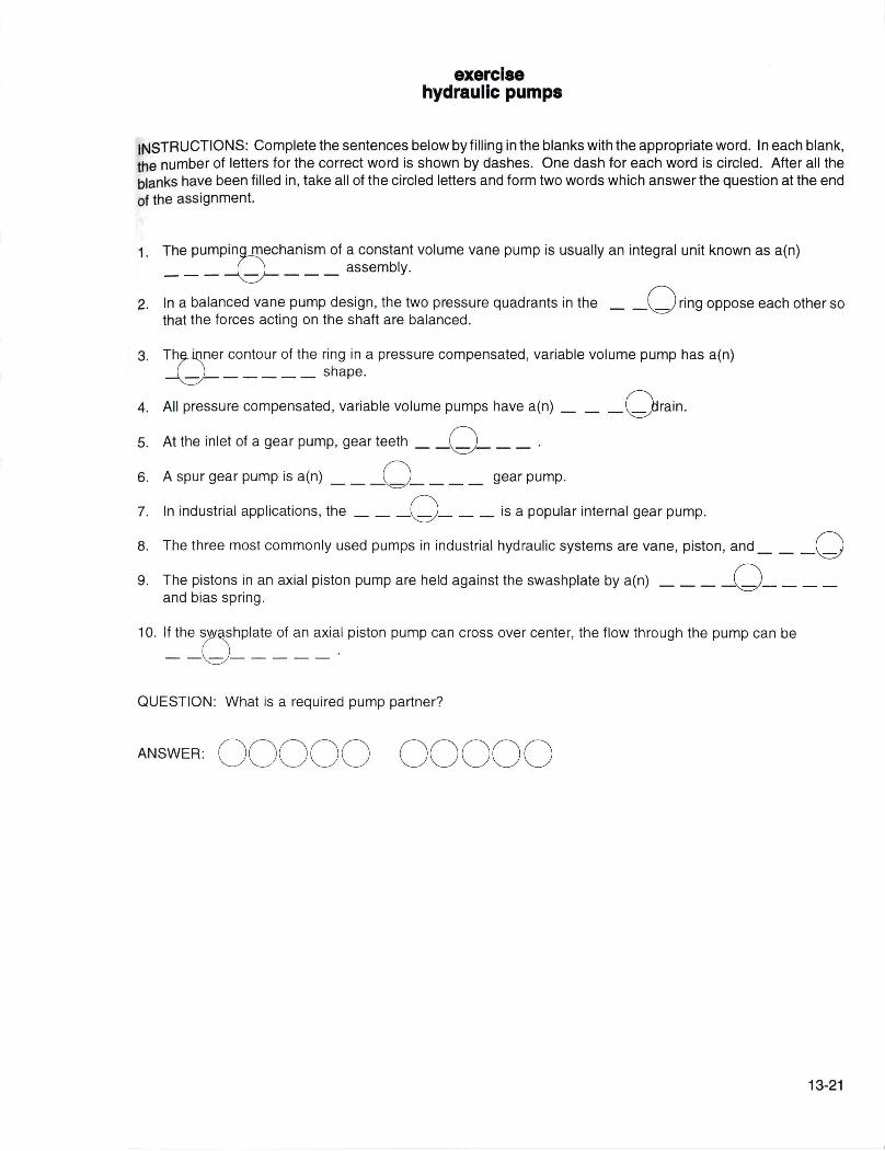
INSTRUCTIONS: Complete the sentences below by filling in the blanks with the appropriate word. In each blank, the number of letters for the correct word is shown by dashes. One dash for each word is circled . After all the blanks have been filled in, take all of the circled letters and form two words which answer the question at the end of the assignment.
1. The pumpin~echanism of a constant volume vane pump is usually an integral unit known as a(n) ___ ~ ___ assembly.
2. In a balanced vane pump design, the two pressure quadrants in the _ -0 ring oppose each other so that the forces acting on the shaft are balanced.
3. ThMner contour of the ring in a pressure compensated, variable volume pump has a(n) ~ _____ shape.
4. All pressure compensated, variable volume pumps have a(n) ___ O rain .
5. At the inlet of a gear pump, gear teeth - -0-__ . 6. A spur gear pump is a(n) __ -0 - _ _ _ gear pump.
7. In industrial applications, the ___ 0 ___ is a popular internal gear pump.
8. The three most commonly used pumps in industrial hydraulic systems are vane, piston, and __ -0 9. The pistons in an axial piston pump are held against the swashplate by a(n) - - - -0 - __ _
and bias spring.
1 O. l~h~c:JhPlate ~ an aXi~1 piston pump can cross over center, the flow through the pump can be
QUESTION: What is a required pump partner?
ANSWER: 00000 00000
13-21