01/2018 MN048019ZU-EN User Manual
125
User Manual 01/2018 MN048019ZU-EN
Transcript of 01/2018 MN048019ZU-EN User Manual

User Manual
01/2018 MN048019ZU-EN

Communications
Manufacturer Eaton Automation GmbH Spinnereistrasse 8-14 CH-9008 St. Gallen Switzerland www.eaton.eu www.eaton.com
Support
Region North America Eaton Corporation Electrical Sector 1111 Superior Ave. Cleveland, OH 44114 United States 877-ETN-CARE (877-386-2273) www.eaton.com
Other regions Please contact your local distributor or send an e-mail to: [email protected]
Original instructions
English
Brand and product names
All brand and product names are trademarks or registered trademarks of the owner concerned.
Copyright
© Eaton Automation GmbH, CH-9008 St. Gallen
All rights, including those of translation, reserved.
None of this documents may be reproduced or processed, duplicated or distributed by electronic
systems in any form (print, photocopy, microfilm or any other process) without the written permission
of Eaton Automation GmbH, St. Gallen.
Subject to alterations

Communications
Imprint
1 General ........................................................................................................................................... 7 1.1 Purpose of this user manual ................................................................................................... 7 1.2 Providing feedback on this user manual ................................................................................ 7 1.3 Additional documentation ....................................................................................................... 7
2 Windows ......................................................................................................................................... 8 2.1 Microsoft Loopback Adapter ................................................................................................... 8
2.1.1 Installation of the Microsoft Loopback Adapter .......................................................... 8 2.1.2 Configuration of the Microsoft Loopback Adapter .................................................... 11
2.2 Adding a Second IP Address to a Network Adapter ............................................................. 12 2.2.1 Verifiying the Second IP Address Is Used ............................................................... 13
3 Hardware ...................................................................................................................................... 15
4 Licensing ...................................................................................................................................... 16 4.1 General ................................................................................................................................. 16
4.1.1 License Administrator .............................................................................................. 16 4.1.2 How to add license points ........................................................................................ 17 4.1.3 Overview showing the license points required for various functionalities ................ 18
5 CODESYS V2 communication .................................................................................................... 19 5.1 Function principle ................................................................................................................. 19
5.1.1 Communication via Ethernet .................................................................................... 19 5.1.2 Connection test ........................................................................................................ 20
5.2 Supported data ..................................................................................................................... 21 5.2.1 Data Type ................................................................................................................ 21 5.2.2 Arrays....................................................................................................................... 21
5.3 Importing tags ....................................................................................................................... 22 5.4 Set up communication to CODESYS V2 device .................................................................. 23
5.4.1 Select Communication ............................................................................................. 23 5.4.2 Configuring PLC parameters ................................................................................... 23 5.4.3 Assigning addresses to PLC tags ............................................................................ 24 5.4.4 Creating a test screen .............................................................................................. 25 5.4.5 Testing a Galileo project .......................................................................................... 26 5.4.6 General information on CODESYS V2 .................................................................... 27 5.4.7 ELAU........................................................................................................................ 27 5.4.8 Turck ........................................................................................................................ 29
6 CODESYS V3 communication .................................................................................................... 30 6.1 Function principle ................................................................................................................. 30 6.2 Communication parameters ................................................................................................. 31
6.2.1 Supported systems .................................................................................................. 31 6.3 Supported data ..................................................................................................................... 31
6.3.1 Addresses ................................................................................................................ 31 6.3.2 Variable type ............................................................................................................ 31 6.3.3 Data Type ................................................................................................................ 32 6.3.4 Structs ...................................................................................................................... 32

Communications
6.3.5 Arrays....................................................................................................................... 32 6.3.6 Unions ...................................................................................................................... 33
6.4 Importing tags ....................................................................................................................... 34 6.5 Fieldbus ................................................................................................................................ 34 6.6 Set up a communication to CODESYS V3 device ............................................................... 34
6.6.1 Setting up communication........................................................................................ 34 6.6.2 Workarounds............................................................................................................ 36 6.6.3 Communication with local runtime system dropping out .......................................... 37
7 Allen Bradley SLC / MicroLogix communication ...................................................................... 38 7.1 Function principle ................................................................................................................. 38
7.1.1 Communication via Ethernet .................................................................................... 38 7.1.2 Serial communications ............................................................................................. 39
7.2 Communication parameters ................................................................................................. 39 7.2.1 Supported systems .................................................................................................. 39
7.3 Communication parameters (serial communication) ............................................................ 40 7.3.1 Supported data ........................................................................................................ 40
7.4 Set up communication to Allen Bradley SLC / MicroLogix device ........................................ 43 7.4.1 Setting up communication – serial interface ............................................................ 43 7.4.2 Setting up communication – Ethernet interface ....................................................... 44 7.4.3 Assigning addresses to tags .................................................................................... 45 7.4.4 Fault messages........................................................................................................ 46
8 Allen Bradley Logix communication.......................................................................................... 49 8.1 Function principle ................................................................................................................. 49
8.1.1 Communication via Ethernet .................................................................................... 49 8.2 Communication parameters ................................................................................................. 50
8.2.1 Supported systems .................................................................................................. 50 8.3 Tag Import ............................................................................................................................ 52 8.4 Set up communication to Allen Bradley Logix device ........................................................... 54
8.4.1 Setting up communication with EtherNet/IP protocol ............................................... 54 8.4.2 Setting up communication DF1 protocol .................................................................. 55
9 Modbus communication ............................................................................................................. 58 9.1 Function principle ................................................................................................................. 58 9.2 Communication parameters ................................................................................................. 58
9.2.1 Supported data types ............................................................................................... 58 9.3 Supported data ..................................................................................................................... 59
9.3.1 Addresses ................................................................................................................ 59 9.3.2 Data interpreter ........................................................................................................ 60
9.4 Cable assembly and termination .......................................................................................... 60 9.4.1 SYSTEM PORT and PC COM(x) method................................................................ 61
9.5 Set up communication to Modbus device ............................................................................. 61 9.5.1 Setting up communication........................................................................................ 61 9.5.2 Assigning addresses to tags .................................................................................... 65 9.5.3 Creating a test screen .............................................................................................. 67 9.5.4 Test Project .............................................................................................................. 68
9.6 Set up communication to Wago I/O System ......................................................................... 70 9.6.1 Function principle ..................................................................................................... 70 9.6.2 Cable assembly and termination.............................................................................. 71 9.6.3 Setting up communication........................................................................................ 71

Communications
9.6.4 Addressing ............................................................................................................... 72 9.6.5 Fault messages........................................................................................................ 73
10 ELC (Eaton Logic Controller) communication .......................................................................... 74 10.1 Function principle ................................................................................................................. 74 10.2 Communication parameters ................................................................................................. 75
10.2.1 Supported systems .................................................................................................. 75 10.3 Supported data ..................................................................................................................... 76
10.3.1 Addresses ................................................................................................................ 76 10.4 Cable assembly and termination .......................................................................................... 76 10.5 Set up communication to ELC device .................................................................................. 77
10.5.1 Setting up ELC generic ASCII and ELC-PV ASCII communications ....................... 77 10.5.2 Setting up ELC generic RTU and ELC-PV RTU communications ........................... 79 10.5.3 Setting up ELC generic TCP and ELC-PV TCP communications............................ 81 10.5.4 Assigning addresses to tags .................................................................................... 82
11 SIMATIC S7 communication ....................................................................................................... 83 11.1 Function principle ................................................................................................................. 83
11.1.1 Panel on MPI/PROFIBUS-DP network .................................................................... 83 11.1.2 Panel on Industrial Ethernet network ....................................................................... 84
11.2 Communication parameters ................................................................................................. 85 11.2.1 Addresses ................................................................................................................ 85 11.2.2 Memory Alignment ................................................................................................... 87 11.2.3 Status Refresh ......................................................................................................... 87 11.2.4 Default Slot .............................................................................................................. 87
11.3 Importing tags ....................................................................................................................... 88 11.3.1 Data Type ................................................................................................................ 89 11.3.2 User-defined types ................................................................................................... 90 11.3.3 Marker bits ............................................................................................................... 90 11.3.4 Arrays....................................................................................................................... 90 11.3.5 Reimport .................................................................................................................. 91
11.4 Set up communication to SIMATIC S7 device ..................................................................... 91 11.4.1 Setting up communication – Siemens MPI .............................................................. 91 11.4.2 Setting up communication – Siemens Industrial Ethernet ....................................... 93 11.4.3 Startup Delay ........................................................................................................... 93 11.4.4 MPI/PROFIBUS Station No. .................................................................................... 94 11.4.5 MPI/PROFIBUS S7-Subnet-ID ................................................................................ 96 11.4.6 IP Address ............................................................................................................... 96
11.5 Setting up communication to – Siemens – S7 Profibus Standard Profile ............................. 98 11.5.1 General .................................................................................................................... 98 11.5.2 Hardware requirements ........................................................................................... 98 11.5.3 SIMATIC network settings ....................................................................................... 98 11.5.4 Setting up communication – Siemens S7 Profibus Standard Profile ....................... 99 11.5.5 Fault messages...................................................................................................... 101 11.5.6 Bug Fix ................................................................................................................... 101
12 SIMATIC S7 / 200 PPI communication ..................................................................................... 103 12.1 Function principle ............................................................................................................... 103
12.1.1 Panel on PROFIBUS network ................................................................................ 103 12.2 Communication parameters ............................................................................................... 104
12.2.1 Addresses .............................................................................................................. 104

Communications
12.2.2 Strings .................................................................................................................... 106 12.2.3 Memory Alignment ................................................................................................. 107
12.3 Set up communication to SIMATIC S7 / 200 PPI device .................................................... 107 12.3.1 Setting up communication – SIMATIC S7 / 200 PPI .............................................. 107 12.3.2 Fault messages...................................................................................................... 108 12.3.3 Bug Fix ................................................................................................................... 108
13 Beckhoff TwinCAT communication ......................................................................................... 110 13.1 Function principle ............................................................................................................... 110 13.2 Tag addressing ................................................................................................................... 110 13.3 Importing Tags ................................................................................................................... 111
13.3.1 TwinCAT 2 ............................................................................................................. 111 13.3.2 TwinCAT 3 ............................................................................................................. 111
13.4 Setting up communication with a Beckhoff TwinCAT device ............................................. 113 13.5 The AmsNetId .................................................................................................................... 115
13.5.1 Adding the AMS route of the panel to the Beckhoff TwinCAT device .................... 116 13.6 Galileo Open and TwinCAT ................................................................................................ 117
13.6.1 Operating principle ................................................................................................. 117 13.6.2 TwinCAT PLC and GRS on the same PC.............................................................. 118 13.6.3 TC3 Workbench (TwinCAT PLC Control) and GRS on the same PC .................... 120
14 Fault messages .......................................................................................................................... 124
15 Bibliography ............................................................................................................................... 125

Communications
1 General
1.1 Purpose of this user manual
This user manual contains the information needed in order to connect Eaton Automation automation
components to Galileo communications.
This user manual goes over the necessary installation and configuration steps. It does not, however,
go over the corresponding operating system or application software.
1.2 Providing feedback on this user manual
If you have any comments, recommendations, or suggestions regarding this user manual, please
send them to [email protected].
1.3 Additional documentation
The following documents may also come in handy.
The following documents may be helpful in the use of the device in addition to this document. These
can be downloaded from our home page (www.eaton.eu):
MN05010007Z
System description Windows CE
MN05010009Z
System Description – Networks in Brief
MN05003003E
Eaton Logic Controller – Programming Manual
MN05003006E
Eaton Logic Controller – Operation Manual
AP048003EN
Product Application – Galileo Training: ELC Driver and Tag Import
MN04802060Z
SIMATIC S7 PG Router User Manual

Communications
2 Windows
2.1 Microsoft Loopback Adapter
2.1.1 Installation of the Microsoft Loopback Adapter
The following description shows how to install a Loopback adapter within Windows. The shown
screen shots are taken from a Windows 7 system.
1. Open the “Add Hardware Wizard”, either via the Control Panel or via the “Run” dialog
(“Start” “Accessories” “Run”, or Win+R) and then type “hdwwiz”. Click on “Next”.
2. The dialog as shown in Fig. 1 appears. Check “Install the hardware that I manually select
from a list” and click on “Next”.
Fig. 1 Add a new hardware
3. Scroll down and select the “Network adapters” in the list, as shown in Fig. 2, then press
“Next”.

Communications
Fig. 2 Selecting hardware type to be installed
4. On the left side in the “Manufacturer” section select “Microsoft” and choose on the right side
the “Microsoft Loopback Adapter”, as displayed in Fig. 3. Then press “Next”.
Fig. 3 Select the hardware to be installed
5. The confirmation dialog as shown in Fig. 4 appears. Click “Next”.

Communications
Fig. 4 Loopback Adapter installation confirmation dialog
6. After successful installation the dialog as shown in Fig. 5 is displayed. Press the “Finish”
button to close the installation wizard.
Fig. 5 Dialog confirming successful Loopback Adapter installation

Communications
2.1.2 Configuration of the Microsoft Loopback Adapter
1. To configure the Loopback Adapter open the “Network Connections”. This is done by either
open the “Control Panel” then go to “Network and Sharing Center”, then to “Change
adapter settings”, or open the “Run” dialog (Win+R) and type “ncpa.cpl”.
2. Open the “Properties” dialog of the connection labeled “Local Area Connection”. The dialog
as shown in Fig. 6 appears.
Fig. 6 Properties dialog for the “Local Area Connection”
3. Uncheck all items expect “Internet Protocol Version 4 (TCP/IPv4)”.
4. Go to the properties of “Internet Protocol Version4 (TCP/IPv4)”.
5. Enter an IP address from the private IP address range which is always immediately
available, even if a network cable is not plugged into the target system. An example is
shown in Fig. 7.

Communications
Fig. 7 The “Internet Protocol Version 4 (TCP/IP)” properties dialog for the “Local Area Connection”
6. Confirm the inserted data by clicking “OK”.
2.2 Adding a Second IP Address to a Network Adapter
1. Open the “Network Connections”, as described in section 2.1.2.
2. Then open the “Properties” dialog of the Network Adapter to which one wants to add the
second IP address.
3. In the item list of the “Properties” dialog select the “Internet Protocol Version 4 (TCP/IPv4)”
and click on “Properties”. A dialog similar to the one shown in Fig. 7 appears.
4. Click on the “Advanced…” button. Then the dialog “Advanced TCP/IP Settings” opens,
similar to the image shown in Fig. 8.

Communications
Fig. 8 Advanced properties settings of a Network Adapter
5. Click on the upper “Add...” button.
6. Add in the opening dialog, labelled as “TCP/IP Address”, the new IP address and subnet
mask pair. Then confirm with the “Add” button. The added IP address should now appear
also in the dialog shown in Fig. 8.
7. Confirm all dialogs with “OK”.
2.2.1 Verifiying the Second IP Address Is Used
In order to check that a second IP address was successfully added, one can run the “ipconfig”
command within a cmd shell, as shown in Fig. 9.
Fig. 9 Example print out of “ipconfig” command

Communications

Communications
3 Hardware
For information on installation, wiring, and commissioning, please refer to the operator manuals for
the devices.

Communications
4 Licensing
For information on installation, wiring, and commissioning, please refer to the operator manuals for
the devices.
4.1 General
The panels feature an integrated licensing system. Each function used will require a certain number
of license points. Moreover, certain device models will already come with a specific number of license
points. The current number of license points will be shown when the panel is started, as well as in the
System Information dialog box.
Note: Licensing is only required for advanced/optional functionalities! Licenses must be added specifically for each individual device, i.e., the activation code provided by the distributor will only work on the MICRO PANEL with the appropriate serial number!
4.1.1 License Administrator
Fig. 10 License Administrator
License Administrator can be used to add license points to a device. Serial: Shows the device's serial number. This number is printed on the device's nameplate. Points: This field will show the number of device license points currently installed.
Change License: If you press this button, a keypad that can be used to manually enter an activation
code will appear. Please refer to the How to add license points section as well.

Communications
Display pane
This field will show the applications and drivers that are currently running and that require license
points. Within this context, "Withdrawn" and "Rejected" mean the following:
Withdrawn This is the number of license points being used by the applications
shown.
Rejected The system does not have enough license points for the applications shown.
Note: License points being used by an application will remain unavailable even after the application is closed, i.e., they will not become available again until the device is restarted. License points cannot be removed from a device.
4.1.2 How to add license points
With a license product certificate:
Fill out the license product certificate completely. All other information needs to be gathered from the
license product certificate. After this, you will be sent an e-mail with the activation code corresponding
to your order. This e-mail will also include a description of how to activate the points on your device.
The License Administrator section shows one way to activate these points.
Without a license product certificate:
Please contact your panel's distributor. The following information will be required in order to place a
license point order:
The functionalities you want
The serial numbers for all the panels to which you want to add license points
Note: You can find the serial number on the device's nameplate, as well as in the System Information and License Administrator dialog boxes.

Communications
4.1.3 Overview showing the license points required for various functionalities
Communication Licence points
Panel PC
Allen Bradley – Logix – DF1 40 40
Allen Bradley – Logix – EtherNet/IP 40 40
Allen Bradley – SLC 5/03 – MicroLogix – DF1 40 40
Beckhoff – TwinCAT TCP/IP 80 80
CODESYS V2 401 80
CODESYS V3 402 80
ELC generic ASCII 40 40
ELC generic RTU 40 40
ELC generic TCP 40 40
ELC-PV ASCII 40 40
ELC-PV RTU 40 40
ELC-PV TCP 40 40
Modbus ASCII 40 40
Modbus RTU 40 40
Modbus TCP 40 40
Persistent Tag Storage - -
Siemens – Industrial Ethernet 40 40
Siemens – MPI 40 –
Siemens – PPI 40 –
Siemens – S7 Profibus Standard Profile 40 –
Universal protocol – TP3 40 40
Tab. 1 Overview showing the license points required for the various communication options
1 Points are only deducted if the PLC is not running locally 2 See 1

Communications
5 CODESYS V2 communication
5.1 Function principle
The CODESYS V2 programming tool generates a symbol file that needs to be transferred to the PLC
being used. When it starts, GRS will read this symbol file from the PLC and use it to assign symbolic addresses to the tags in the PLC.
It is important to make sure that the tags in the PLC and in Galileo are declared with the same
address and that their data types match. Moreover, structures and arrays must have the exact same
structure.
Addresses are assigned (syntax) based on standard IEC 61131-3, and all common data types are
supported, e.g.: <tag> <tag>.<arrayindex>[] <struct>.<tag> <struct>.<tag>.<arrayindex>[] <prog>.<tag> <prog>.<tag>.<arrayindex>[] <prog>.<struct>.<tag> <prog>.<struct>.<tag>.<arrayindex>[]
Note: It is no longer necessary to output field components for arrays in the PLC project's symbol configuration. Outputting the group entries is sufficient. This can reduce the symbol file's size significantly, resulting in faster data synchronization and more efficient space usage.
5.1.1 Communication via Ethernet
To ensure efficient commissioning, you will need to set up a small network as illustrated in the following diagram:
Ethernet
192.168.1.86
192.168.1.20
192.168.1.87

Communications
Note: The IP addresses used here are only an example! What is important is for each individual device to be assigned its own unique IP address.
The following software must already be installed on your computer, and you must be familiar with its use:
- CODESYS V2 PLC programming software
- Galileo HMI visualization software
For information on the required IP address and subnet mask settings, please refer to the
documentation for PLC you are using.
5.1.2 Connection test
Use the "PING.EXE" command prompt command to make sure that every network node can be
reached.
Fig. 11 Pinging an address
Fig. 12 Ping dialog box

Communications
If the connection is working properly, the PLC and the HMI will respond as shown in the screenshot
above, but with the actual IP address being used.
5.2 Supported data
5.2.1 Data Type
Declare the tags on the "CODESYS V2" using a supported data type:
Data type Comment
BOOL –
SINT –
USINT, BYTE The communication server does not distinguish between USINT and BYTE.
INT –
UINT, WORD The communication server does not distinguish between UINT and WORD.
DINT –
UDINT, DWORD The communication server does not distinguish between UDINT and DWORD.
REAL –
STRING –
TIME TIME is mapped to DWORD on the client.
DATE DATE is mapped to DWORD on the client.
TIME_OF_DAY TIME_OF_DAY is mapped to DWORD on the client.
DATE_AND_TIME DATE_AND_TIME is mapped to DWORD on the client.
Subrange types Limits need to be defined manually on the client.
Enumerated types Keep the enumeration's underlying data type in mind (default: INT). If a value that is not defined in the enumerated type is written, it will not be captured.
Tab. 2 Supported data types
The following primitive data types are not supported as of this writing: LREAL POINTER REFERENCE
5.2.2 Arrays
Multi-dimensional arrays of primitive data types must be declared as several single-dimensional
arrays. The higher dimensional indices are added comma separated in brackets to the variable name
or the <tag> part of the address.

Communications
Fig. 13 Multi-dimensional array
One or more dimensional arrays of structures or strings must be declared as single elements. The
indices are added comma separated in brackets to the variable name or the <tag> part of the
address.
Fig. 14 Array of structures
5.3 Importing tags
Galileo supports the import of tags from CODESYS V2 Symbol tables using the XML format
(*.sym_xml). Symbol tables must always be generated with the export data entries option from
CODESYS V2 enabled.
User-defined data types are generated automatically and all supported data gets imported.

Communications
In case of a re-import already existing tags will be merged with new tags based on their addresses. If
the merging based on the addresses fails the tag names are considered as well.
5.4 Set up communication to CODESYS V2 device
5.4.1 Select Communication
Open Galileo and create a new project for your PANEL.
Fig. 15 PLC – Selection and Configuration – CODESYS V2
5.4.2 Configuring PLC parameters
In the "PLC Selection" screen, select the appropriate "Interface" and "Model" as shown in the screenshot above.
Communication parameters Comment
Level (2, 4): This parameter can be used to optimize communication performance. If you cannot find any specific information for your PLC in this document, leave this parameter with its default value of 4 (optimized).
Status Refresh [s]: For more information, read the online help for your Galileo version.
Port number Enter the port number that the PLC will use to provide the communication service. The default port for this service is 1200. Some PLCs may use other ports for this service. In this case, please contact the PLC's manufacturer or consult the documentation for the PLC if you are unable to find any specific

Communications
information for your PLC in this document.
Break [ms]: General pause, in milliseconds, required between two communication cycles. Since Galileo uses polling for this communication method and polling is usually extremely fast, it may be necessary to configure a pause. On one hand, to reduce the load on the network; on the other, to reduce the load on the PLC (default: 1 ms).
Startup Delay [s]: Please refer to the help for Galileo.
IP Address or Hostname: Enter the PLC's IP address or hostname. In the example used in this document, the IP address is 192.168.1.87. If the PLC and GRS are running on the same device, you may enter "localhost" as the address. This will be the case, for example, when CODESYS and Galileo are running on the same panel.
Min. Cycle Time [ms]:
Endian Mode: For PLCs that use "Intel byte order," set this parameter to "Little endian" (default). For PLCs that use "Motorola byte order," set the parameter to "Big endian."
5.4.3 Assigning addresses to PLC tags
In Galileo, tags are assigned addresses like in the PLC, as per IEC 61131-3, using symbolic names.
The PLC in our example has the structure shown in the screenshot below. Now create the same
structure in Galileo.
Note: For information on how to import tags from CODESYS V2, please refer to the documentation for Galileo.
Fig. 16 Setting an address
Whenever possible, use the same name as in the PLC!

Communications
Corresponding declaration in the PLC:
TYPE TimerType1 : STRUCT
Description : STRING[21]; Day : BYTE; Month : BYTE; Year : BYTE; Seconds : BYTE; Minutes : BYTE; Hours : BYTE; Value : BOOL; Days : BYTE; Active : BYTE; TimerNr : BYTE;
END_STRUCT END_TYPE
VAR_GLOBAL TimerStruct: TimerType1; END_VAR
5.4.4 Creating a test screen
Now create a new screen, add a "Value Display/Entry" control to it, and assign "TimerStruct.Year" to
the control.
Fig. 17 "TimerStruct Year" screen
The project is now ready and can be tested directly on your computer.

Communications
5.4.5 Testing a Galileo project
Now compile the project and start Galileo Runtime by clicking on the "Build and Deploy" button.
Fig. 18 Compile Project
Galileo Runtime will establish an active connection to the PLC, after which you will be able to set the
"TimerStruct.Year" tag to the value you want.
Note: By default, communication will be disabled in the Design Tool. It needs to be explicitly turned on by going to Home -> Simulator -> ... -> Build & Simulator -> Simulator settings and enabling the "Communications active…" checkbox.
Exit Galileo Runtime by clicking on the "X" icon in the upper right corner or using a configured "exit"
function, then run it again. If the last value you entered is shown, this means that everything has been
configured properly.
You can now transfer the project to your panel and then start GRS (Galileo Runtime System). For more information, please refer to the documentation for Galileo.
Ethernet
192.168.1.86
192.168.1.87

Communications
Note: Normally, the PLCs can handle multiple connections simultaneously, meaning you can connect both Galileo Runtime from the Design Tool and Galileo Runtime on the panel at the same time.
If multiple GRS instances are communicating with the same CODESYS V2 PLC, there will be a higher load on the panel's CPU in comparison to when only one instance is communicating with the PLC. In this case, it may be necessary to set the "Break" and/or "Min. Cycle Time" communication parameters to a higher value.
5.4.6 General information on CODESYS V2
Following are a couple of examples:
Eaton Automation CODESYS
WAGO IO-Pro
ELAU EPAS
Note: Please make absolutely sure that the names of the CODESYS V2 and Galileo tags match each other exactly, as the system will not be able to establish communications otherwise.
5.4.7 ELAU
The following information only provides specific instructions and settings.
Eaton Automation does not provide support for the EPAS programming toolkit. If you have any
questions, please contact the developer directly.

Communications
5.4.7.1 PacDrive C / PacDrive P
Select port number 5000 and level 4 for these devices, as shown in the screenshot below.
Fig. 19 PacDrive C / PacDrive P

Communications
5.4.8 Turck
The following information only provides specific instructions and settings.
5.4.8.1 Blxx-PG-EN
For the BLxx-PG-EN, select port number 1202, level 2, and big endian mode, as shown in the
screenshot above.
Fig. 20 Blxx-PG-EN
Note: The PANEL and the BLxx-PG-EN must be on the same subnet.
There can only be one connection to the BLxx-PG-EN at a time, i.e., the programming tool and the PANEL cannot communicate with the BLxx-PG-EN simultaneously.

Communications
6 CODESYS V3 communication
6.1 Function principle
Multiple clients can address the communication server used in a CODESYS V3 runtime system. The
CODESYS V3 runtime system is preferentially identified using the corresponding node name,
although connections can also be set up using the relevant IP address. The aforementioned node
name can be viewed and changed using the CODESYS V3 configuration software. It is important to
note that the server can be connected to any CODESYS V3 network hierarchy level, as this will have
no impact on its proper operation.
Fig. 21 How it works without a CODESYS V3 router
Fig. 22 How it works with a CODESYS V3 router

Communications
6.2 Communication parameters
6.2.1 Supported systems
6.2.1.1 Client
The following devices can communicate with a "CODESYS V3" runtime system:
PC with Galileo Open and an Ethernet port
XV series panels (exceptions: XVC100, XVC600)
Starting here, the term "client" will be used in order to refer to these devices and the software running
on them.
6.2.1.2 Server:
As of this writing, the following runtime systems are NOT supported:
Bosch Rexroth CODESYS V3
CODESYS V3 with big-endian byte order (=Motorola) As of this writing, the following runtime systems are supported:
CODESYS Control RTE Version 3.5.5 and higher
CODESYS Control Win Version 3.3 and higher
Starting here, the term "CODESYS V3" will be used in order to refer to these devices and the
software running on them.
6.3 Supported data
6.3.1 Addresses
Addresses can be assigned to tags at all levels within an application.
Set up the addresses on the "CODESYS V3" and the client, keeping in mind that the addresses are
case-sensitive and must match.
6.3.2 Variable type
Declare the tags on the "CODESYS V3" using a supported tag type:
VAR [ RETAIN | PERSISTENT ]
VAR_GLOBAL [ RETAIN | PERSISTENT ]
VAR_INPUT
VAR_OUTPUT

Communications
6.3.3 Data Type
Declare the tags on the "CODESYS V3" using a supported data type:
Data Type Comment
BOOL –
SINT –
USINT, BYTE The communication server does not distinguish between USINT and BYTE.
INT –
UINT, WORD The communication server does not distinguish between UINT and WORD.
DINT –
UDINT, DWORD The communication server does not distinguish between UDINT and DWORD.
REAL –
STRING –
WSTRING –
TIME TIME is mapped to DWORD on the client.
DATE DATE is mapped to DWORD on the client.
TIME_OF_DAY TIME_OF_DAY is mapped to DWORD on the client.
DATE_AND_TIME DATE_AND_TIME is mapped to DWORD on the client.
Subrange types Limits need to be defined manually on the client.
Enumerated types Keep the enumeration's underlying data type in mind (default: INT). If a value that is not defined in the enumerated type is written, it will not be captured.
Tab. 3 Supported data types
The following data types are not supported as of this writing: LREAL LINT ULINT LWORD LTIME POINTER REFERENCE
6.3.4 Structs
Structures are read element by element. The structures on the "CODESYS V3" can also contain tags
with unsupported data types, provided these tags are not used by any of the clients.
6.3.5 Arrays
Multi-dimensional arrays of primitive data types must be declared as several single-dimensional
arrays. The higher dimensional indices are added comma separated in brackets to the variable name
or the <tag> part of the address.

Communications
Fig. 23 Mutli-dimensional array in CODESYS V3 Fig. 24 Mutli-dimensional array in Galileo
One or more dimensional arrays of structures or strings must be declared as single elements. The
indices are added comma separated in brackets to the variable name or the <tag> respectively the
<struct> part of the address.
Fig. 25 Array von Strukturen
6.3.6 Unions
The individual components of a union must be declared client-side as separate variables.

Communications
Fig. 26 Union Definition in CODESYS V3 Fig. 27 Union in Galileo
6.4 Importing tags
Galileo supports the import of tags from CODESYS V3 Symbol tables (*.xml).
User-defined data types are generated automatically and all supported data gets imported.
In case of a re-import already existing tags will be merged with new tags based on their addresses. If
the merging based on the addresses fails the tag names are considered as well.
6.5 Fieldbus
The client features an Ethernet port that can be used to connect it to the Ethernet network.
If the "CODESYS V3" also features an Ethernet port, it can be connected directly to the Ethernet
network.
If the "CODESYS V3" does not feature an Ethernet port, a CODESYS V3 router (runtime system or
gateway) must be used.
Please note: Differently configured subnet masks within a network segment can result in a client not
being able to establish a connection to the CODESYS V3 runtime system.
Limitation: The client can only be run at the highest level of the CODESYS V3 network hierarchy.
6.6 Set up a communication to CODESYS V3 device
The Galileo visualization program supports the use of multiple parallel communication channels. One
communication channel is needed for each application in a "CODESYS V3." And, if necessary, you
can instead set up multiple communication channels for a single application in a "CODESYS V3."
6.6.1 Setting up communication
Select "CODESYS V3" and configure the communication parameters as required.

Communications
Fig. 28 Configuring communications in Galileo without authentication parameters
Communication parameters Comment
Status Refresh Read the online help for your Galileo version.
Startup Delay Read the online help for your Galileo version.
Node/Application Name Enter the node name and the application name for the "CODESYS V3" in this field (use "/" as a separator). Note: If there is no application name, use "/" at the end of the node name. For example: if the node name is "MyHost", you would enter "MyHost/" into the field.
User/Password Enter the username for the "CODESYS V3" Enter the password for the "CODESYS V3" (use "/" as a separator).
Tab. 4 Communication parameters in Galileo
6.6.1.1 Assigning addresses to PLC tags
Galileo supports the following address formats and data types:
Galileo CODESYS V3
<object>.<tag> Tag in object
<object>.<tag>.<array index>[ ] Array in object
<object>.<struct>.<tag> Tag in a structure in the object
<object>.<struct>.<tag>.<array index>[ ] Array in a structure in the object

Communications
<object>.<struct> Structure in object
Galileo (CODESYS V2-compatible) CODESYS V3 { attribute 'namespace':= '' }
<tag> Tag in global tag list
<tag>.<array index>[ ] Array in global tag list
<struct>.<tag> Tag in a structure in the global tag list
<struct>.<tag>.<array index>[ ] Array in a global structure in the global tag list
<struct> Structure in global tag list
Tab. 5 Address formats in Galileo
Galileo CODESYS V3
Bit BOOL
Error bit BOOL
Signed byte SINT
Unsigned byte USINT, BYTE
Signed word INT
Unsigned word UINT, WORD
Signed double word DINT
Unsigned double word UDINT, DWORD
Float REAL
String STRING, WSTRING
Tab. 6 Data types in Galileo
6.6.2 Workarounds
6.6.2.1 Migrating from CODESYS V2 to CODESYS V3
The various tags in CODESYS V2 are stored in a different way in CODESYS V3:
Tag CODESYS V2 CODESYS V3
Global tag (variable) .globalVar App1.GVL.globalVar
Tag (variable) in program PLC_PRG.lokalVar App1.PLC_PRG.lokalVar
Tab. 7 CODESYS V2 / CODESYS V3 addresses
When using global tags in CODESYS V3, the name of the global tag list is added to the name of the application. This means that all the addresses for the global tags from CODESYS V2 would have to be modified. If it is not possible to automatically modify the addresses as required, there are two workarounds available:
CODESYS V3-compatible addresses
CODESYS V2-compatible addresses

Communications
6.6.2.2 CODESYS V3-compatible addresses
On the client, configure a separate communication channel for access to the global tags. In the "Application" parameter for this communication channel, enter both the name of the application and the name of the global tag list, separated by a point. Example: App1.GVL
6.6.2.3 CODESYS V2-compatible addresses
Current CODESYS V3 versions support address compatibility with CODESYS V2 by means of the { attribute 'namespace':= '' } construct. The client will be able to use this method if you leave the "Application" parameter empty. Please note that the client will require at least one tag in the global tag list in this case.
6.6.3 Communication with local runtime system dropping out
If the client and "CODESYS V3" are running on the same device, the CODESYS V3 runtime system will terminate an active communication channel under certain circumstances. The communication channel will be selected using the following method:
If there are one or more IP adapters, one of the IP adapters will be used.
If there are no IP adapters, "localhost" will be used. The number of IP adapters may change during operation if, for example, a cable is connected or disconnected. This may result in communication between the client and "CODESYS V3" dropping out for about half a minute. You can avoid this problem by installing "Microsoft Loopback Adapter" and assigning it an IP address. This way, there will always be an IP adapter and "localhost" will not need to be used. When establishing a connection , the client will give preference to "Microsoft Loopback Adapter."

Communications
7 Allen Bradley SLC / MicroLogix communication
Both the "client" and the "controller" feature an RS232 interface that can be used to connect them.
In addition, MicroLogix controllers can be optionally connected via Ethernet. For information on
installation, wiring, and commissioning, please refer to the operator manuals for the devices.
7.1 Function principle
7.1.1 Communication via Ethernet
This communication method uses the EtherNet/IP protocol via the Ethernet port. Communication
takes place between a panel, or a PC, and exactly one "controller" via Ethernet.
Fig. 29 How Ethernet communication works

Communications
7.1.2 Serial communications
This communication method uses the DF1 protocol via the RS232 interface. Communication takes
place between a panel, or a PC, and exactly one "controller" via RS232.
Fig. 30 How serial communication works
7.2 Communication parameters
7.2.1 Supported systems
7.2.1.1 Client
The following devices can communicate with Communications:
PC with Galileo Open and RS232 interface
XV series panel with RS232 interface
M series panel with RS232 interface
Starting here, the term "client" will be used in order to refer to these devices and the software
running on them.

Communications
7.2.1.2 Server:
The following "controllers" are supported:
SLC 5/03 (RS232 interface)
SLC 5/04 (RS232 interface)
SLC 5/05 (RS232 interface)
MicroLogix (RS232 port and Ethernet interface)
Starting here, the term "controller" will be used in order to refer to these devices.
7.3 Communication parameters (serial communication)
The baud rate settings for the "client" and the "controller" must be identical.
The "client" uses node address 0.
Configure the Ethernet interface for the "controller" as follows:
Node address: 1
System Mode
DF1 Full Duplex
8 Data Bits, Even Parity, 1 Stop Bit
No Handshaking
BCC or CRC Error Detection
1000 ms ACK Timeout
3 NAK Retries
3 ENQ Retries
7.3.1 Supported data
7.3.1.1 Addresses
designation Address range
B-File B0:0 … B255:255
N-File N0:0 … N255:255
F-File F0:0 … F255:255
Tab. 8 Supported addresses
In addition to the files listed above, timer and counter scans are also supported for Ethernet
communication.

Communications
The available address ranges are as follows:
designation Address range
T-File T0:0 … T255:255
C-File C0:0 … C255:255
Tab. 9 Supported addresses
7.3.1.2 Timer
The timer consists of three word data blocks.
Word Bit
0 … 12
13
14
15
0 Used internally only
DN TT EN
1 Default value
2 Accumulated value
Tab. 10 DN = Timer Date Bit
TT = Timer Timing Bit
EN = Timer Enable Bit
A value array with 3 elements needs to be created in order to make the entire data block accessible
on the HMI.
Fig. 31 Timer Array
The data block's start address is specified as usual.

Communications
Fig. 32 Setting the address

Communications
7.3.1.3 Counter
The counter consists of three word data blocks.
Word Bit
0 … 8
11
12
13
14
15
0 Not Used UN OV DN CD CU
1 Preset value
2 Accumulated value
Tab. 11 UN = Count Underflow Bit
OV = Count Overflow Bit
DN = Count Done Bit
CD = Count Down Enable Bit
CU = Count Up Enable Bit
To create counter tags, follow the same steps described for the timer in 2.4.2.
7.4 Set up communication to Allen Bradley SLC / MicroLogix device
The Galileo visualization program supports the use of multiple parallel communication channels. One
"controller" will take up one serial interface exclusively.
7.4.1 Setting up communication – serial interface
Select "A. Bradley – SLC 5/03 – MicroLogix – DF1" and configure the communication parameters
as required.

Communications
Fig. 33 Configuring communications in Galileo – serial interface
Communication parameters Comment
Status Refresh [s]: For more information, read the online help for your Galileo version.
Min. Cycle Time [ms]: For more information, read the online help for your Galileo version.
Endian Mode: For more information, read the online help for your Galileo version.
Baud Rate: The baud rates for the "client" and "controller" must be identical.
Memory alignment inside structures:
For more information, read the online help for your Galileo version.
Tab. 12 Communication parameters
7.4.2 Setting up communication – Ethernet interface
Select "A. Bradley – MicroLogix – EtherNet/IP" and configure the communication parameters as
required.

Communications
Fig. 34 Configuring communications in Galileo – Ethernet interface
Communication parameters Comment
Status Refresh [s]: For more information, read the online help for your Galileo version.
IP Address or Hostname: IP address or hostname Example: 192.168.1.1
Min. Cycle Time [ms]: For more information, read the online help for your Galileo version.
Endian Mode: For more information, read the online help for your Galileo version.
Memory alignment inside structures:
For more information, read the online help for your Galileo version.
Tab. 13 Communication parameters
7.4.3 Assigning addresses to tags
Galileo supports the following address formats and data types:
Galileo Controller
B%d:%d C%d:%d F%d:%d N%d:%d T%d:%d
Tags on the controller.

Communications
Tab. 14 Address formats in Galileo
Galileo Controller
Bit / Error B, N
Byte: B, N
Word B, C, N, T
DWord not supported
Float F
String not supported
Structure B, N
System B, N
Tab. 15 Data types in Galileo
7.4.4 Fault messages
7.4.4.1 Local STS error codes
Local STS error codes contain errors that can occur in the local node. Following are the various
possible error codes (in hex):
Code Description
00 Success; no error
01 DST Node is out of buffer space
02 Cannot guarantee delivery; link layer The remote node specified does not ACK command
03 Duplicate token holder detected
04 Local port is disconnected
05 Application layer timed out waiting for response
06 Duplicate node detected
07 Station is offline
08 Hardware fault
Tab. 16 Local STS error codes
Local STS codes 09 to 0F (hex) are not used.

Communications
7.4.4.2 Remote STS Error Codes
Remote STS error codes contain errors that can occur in remote nodes. Following are the various
possible error codes (in hex) that can occur in the STS byte:
Code Description
00 Success; no error
10 Illegal command or format
20 Host has a problem and will not communicate
30 Remote node host is missing, disconnected, or shut down
40 Remote host could not complete function due to hardware fault
50 Addressing problem or memory protect rungs
60 Function not allowed due to command protection selection
70 Processor is in Program Mode
80 Compatibility mode file missing or communication zone problem
90 Remote node cannot buffer command
A0 Wait ACK (1775 KA buffer full)
B0 Remote node problem due to download
C0 Wait ACK (1775 KA buffer full)
D0 Not used
E0 Not used
F0 Error code in EXT STS byte (see tab. 13)
Tab. 17 Remote STS Error Codes
7.4.4.3 EXT STS byte
If the STS code is F0 (hex), there will be an EXT STS byte.
EXT STS codes for CMD
Hex Code Description
0 Not used
1 A field has an illegal value
2 Fewer levels specified in address than minimum for any address
3 More levels specified in address than system supports.
4 Symbol not found
5 Symbol is of improper format

Communications
6 Address does not point to something usable
7 File is wrong size
8 Cannot complete request; situation has changed since start of the command
9 Data or file size is too large
A Transaction size plus word address is too large
B Access denied; improper privilege
C Condition cannot be generated; resource is not available
D Condition already exists; resource is readily available
E Command cannot be executed
F Histogram overflow
10 Inaccessible
11 Illegal data type
12 Invalid parameter or invalid data
13 Address reference exists to deleted area
14 Command execution failure for unknown reason; possible PLC 3 histogram overflow
15 Data conversion error
16 Scanner not able to communicate with 1771 rack adapter
17 Type mismatch
18 1771 module response was not valid
19 Duplicated label
22 *Remote rack fault
23 *Timeout
24 *Unknown error
1 A File is open; another node owns it
1B Another node is the program owner
1C Reserved
1D Reserved
1E Data table element protection violation
1F Temporary internal problem
Tab. 18 Remote STS error codes
* These codes are used to forward a DH link to a remote I/O link

Communications
8 Allen Bradley Logix communication
8.1 Function principle
The following software must already be installed, and you must be familiar with its use:
Galileo HMI visualization software
RS Logix5000 programming tool
This documentation goes over the following communication options:
A. Bradley - Logix – EtherNet/IP with Ethernet port.
A. Bradley - Logix – DF1 with RS232 interface.
8.1.1 Communication via Ethernet
The connection to the Allen Bradley Logix is made directly using the CPU's or Ethernet
Communication Interface's Ethernet port.
In this regard, no additional parameters need to be configured and no function blocks need to be
enabled.
The panel can communicate with multiple nodes (Allen Bradley Logix) simultaneously.
The station and IP addresses shown above are examples. What is important is for each individual
node to be assigned its own unique station and/or IP address.
Ethernet
192.168.0.2
192.168.0.4
192.168.0.3
192.168.0.41
192.168.0.40

Communications
8.2 Communication parameters
8.2.1 Supported systems
8.2.1.1 Data Types
Galileo data types are mapped to Logix as follows:
Logix Galileo
BOOL BIT
BIT in integer data types BIT `/` notation
SINT BYTE, signed
BYTE, unsigned
INT WORD, signed
WORD, unsigned
DINT DWORD, signed
DWORD, unsigned
REAL FLOAT
STRING STRING
Note: Only the predefined Logix STRING data type with a length of 82 characters is supported. A size of 82 bytes must be defined for a STRING in Galileo. In Logix, this will correspond to 86 bytes (4-byte length information and 82 characters).
8.2.1.2 Predefined Data Type
Galileo supports all predefined data types available in RSLogix 5000 Version 19.01.00.
8.2.1.3 Arrays
Multi-dimensional arrays of primitive data types must be declared as several single-dimensional
arrays. The higher dimensional indices are added comma separated in brackets to the variable name
or the <tag> part of the address.
Example: A tag defined as
_arr3Dim_Variable INT[2,3,8]
in RSLogix must be mapped the following way within Galileo.
1. Create a word array tag as shown in Fig. 35.

Communications
Fig. 35 Create a word array tag
2. Set the array with the last dimension of the tag (_arr3Dim_Variable INT[2,3,8]), as shown in Fig.
36.
Fig. 36 Assign the last dimension of the multi-array dimensions to the array
3. Set the tag name to “_arr3Dim_Variable[0,0]”, i.e. the array tag name as defined in RSLogix
followed by the first and second dimensions in brackets, separated with a comma.
4. Repeat above steps for “_arr3Dim_Variable[0,1]”, “_arr3Dim_Variable[0,2]”,
“_arr3Dim_Variable[0,3]”, “_arr3Dim_Variable[1,0]”, etc.
One or more dimensional arrays of structures or strings must be declared as single elements. The
indices are added comma separated in brackets to the variable name or the <tag> part of the
address.
Communications
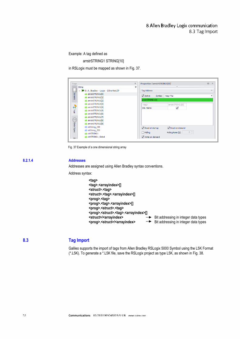
Example: A tag defined as
arrstrSTRING1 STRING[10]
in RSLogix must be mapped as shown in Fig. 37.
Fig. 37 Example of a one dimensional string array
8.2.1.4 Addresses
Addresses are assigned using Allen Bradley syntax conventions.
Address syntax:
<tag> <tag>.<arrayindex>[] <struct>.<tag> <struct>.<tag>.<arrayindex>[] <prog>.<tag> <prog>.<tag>.<arrayindex>[] <prog>.<struct>.<tag> <prog>.<struct>.<tag>.<arrayindex>[] <struct>/<arrayindex> Bit addressing in integer data types <prog>.<struct>/<arrayindex> Bit addressing in integer data types
8.3 Tag Import
Galileo supports the import of tags from Allen Bradley RSLogix 5000 Symbol using the L5K Format
(*.L5K). To generate a *.L5K file, save the RSLogix project as type L5K, as shown in Fig. 38.

Communications
Fig. 38 Example of tag export from RSLogix 5000 in the L5K format
The exported L5K file can be imported in Galileo using the “Import PLC Tags” option, as shown in
Fig. 39.
Fig. 39 Example of how to import a L5K tag information file into Galileo
User-defined data types are generated automatically and all supported data gets imported.
In case of a re-import already existing tags will be merged with new tags based on their addresses. If
the merging based on the addresses fails the tag names are considered as well.

Communications
8.4 Set up communication to Allen Bradley Logix device
8.4.1 Setting up communication with EtherNet/IP protocol
This communication method requires a PANEL with an Ethernet interface. For information on the
communication cable, please consult the Ethernet section in the "Installation Instructions, General
Wiring Information" document.
Regardless of the number of connections, there must be an additional 40 license points available on
the device.
Note: If you have any questions concerning license products, please contact your PANEL distributor.
8.4.1.1 Setting up communication
Fig. 40 Configuring communications in Galileo for A. Bradley Logix – Ethernet/IP
Note: Galileo supports multiple connections for the Ethernet interface, i.e., multiple connections can be configured for the same port. This means that the tags (including the corresponding system structures) on multiple PLCs can be assigned addresses.
Select "A.Bradley – Logix – EtherNet/IP" in the "PLC Selection and Configuration" dialog box. The
dialog box shown above will appear so that you can configure the parameters required for the
corresponding communication method.

Communications
Communication parameters Comment
Status Refresh [s]: For more information, read the online help for your Galileo version.
CPU Slot: Specify the appropriate slot.
Startup Delay [s]: For a description of this parameter, please refer to the documentation for Galileo.
IP Address or Hostname: The IP address entered must match the setting for the Ethernet module in the PLC rack.
Min. Cycle Time:
Endian Mode: This parameter defines how data is organized in the protocol.
Tab. 19 Logix – EtherNet/IP communication parameters
8.4.2 Setting up communication DF1 protocol
This communication method requires a PANEL with an RS232 interface. For information on the
communication cable, please consult the RS232 Port System section in the "Installation Instructions,
General Wiring Information" document.
Regardless of the number of connections, there must be an additional 40 license points available on
the device.
Note: If you have any questions concerning license products, please contact your PANEL distributor.
8.4.2.1 Setting up communication

Communications
Fig. 41 Configuring communications in Galileo – A. Bradley – Logix – DF1
Note: Galileo supports exactly one connection for the RS232 port, i.e., exactly one connection can be configured for each port.
Select "A.Bradley – Logix – DF1" in the "PLC Selection and Configuration" dialog box. The dialog box
shown above will appear so that you can configure the parameters required for the corresponding
communication method.
Communication parameters Comment
Status Refresh [s]: For more information, read the online help for your Galileo version.
Startup Delay [s]: For a description of this parameter, please refer to the documentation for Galileo.
Min. Cycle Time:
Endian Mode: This parameter defines how data is organized in the protocol.
Baud Rate: The baud rate setting must match the setting for the PLC. The other settings for the A. Bradley serial port will be shown in the "Information" pane in the "PLC Selection and Configuration" dialog box.
Tab. 20 Logix – DF1 communication parameters

Communications
Note: The system protocol must be set to "DF1 Point to Point" on the Logix PLC. Error detection can be set to BCC or CRC.

Communications
9 Modbus communication
9.1 Function principle
This documentation describes the connection between a panel and any PLC that supports a Modbus
protocol (ASCII, RTU, TCP).
When using this communication method, the panel will be the master and the PLC will be a slave.
Communication will always be initiated by the panel, and the PLC will respond as appropriate for the
corresponding request.
Modbus protocols use station addresses (STx). Accordingly, both "point-to-point" and "multipoint" connections can be implemented when using the appropriate physical interface (see the figure above).
Note: The Modbus protocol is also available for the panel's SYSTEM PORT. This port is an RS232 interface that is not galvanically isolated.
There is also the option of connecting to a standard PC via COM(x) and implementing communication with Galileo Open (Galileo Runtime System for PC).
9.2 Communication parameters
9.2.1 Supported data types
All configurable data types from Galileo are supported.
ST1 ST2 ST3 ST4 ST1
"Point-to-point" "Multipoint"

Communications
9.3 Supported data
9.3.1 Addresses
As per the protocol, function codes used to access various data storage areas are defined.
For Modbus RTU communication, the panels support the function codes listed below / the
corresponding data storage areas.
Modbus register Galileo Function code Data type Granularity
Read Write
Coil M 0x01 0x0F Bit 1-bits
Discrete Input MI 0x02 - Bit 1-bits
Input Register RI 0x04 - Word 16-bits
Holding Register R 0x03 0x10 Word 16-bits
Galileo Modbus PLC Modbus Galileo
M 0x0F Bit (read/write) 0x01 M
MI Bit (read only) 0x02 MI
RI Wort (read only) 0x04 RI
R 0x10 Wort (read/write) 0x03 R
Note: For information on where the data is ultimately referenced in the PLC, please refer to the documentation for the PLC.

Communications
9.3.2 Data interpreter
According to the original Modbus specification, data fields in the Modbus protocol should be
interpreted using the big-endian format. However, many devices in the field do not interpret data this
way, which is why there is the option to use other modes as necessary. The corresponding parameter
can be configured in "PLC Selection and Configuration."
The following table shows the effect that the various modes have on the data stream based on the
data type being used.
Data byte
Galileo Little Endian Big Endian
Little Endian Twisted
BigEndian Twisted
00 Byte A Byte A Byte A Byte B Byte B
01 Byte B Byte B Byte B Byte A Byte A
02
DWord
DWord[0] LSB DWord[3] MSB DWord[1] DWord[2]
03 DWord[1] DWord[2] DWord[0] LSB DWord[3] MSB
04 DWord[2] DWord[1] DWord[3] MSB DWord[0] LSB
05 DWord[3] MSB DWord[0] LSB DWord[2] DWord[1]
06 Word
Word LSB Word MSB Word MSB Word LSB
07 Word MSB Word LSB Word LSB Word MSB
08 Byte C Byte C Byte C Byte D Byte D
09 Byte D Byte D Byte D Byte C Byte C
10
Bit[32]
Bit 0..7 Bit 0..7 Bit 8..15 Bit 8..15
11 Bit 8..15 Bit 8..15 Bit 0..7 Bit 0..7
12 Bit 16..23 Bit 16..23 Bit 24...31 Bit 24...31
13 Bit 24...31 Bit 24...31 Bit 16..23 Bit 16..23
14
CharArray[6] (String)
CharArray[0] CharArray[0] CharArray[1] CharArray[1]
15 CharArray[1] CharArray[1] CharArray[0] CharArray[0]
16 CharArray[2] CharArray[2] CharArray[3] CharArray[3]
17 CharArray[3] CharArray[3] CharArray[2] CharArray[2]
18 CharArray[4] CharArray[4] CharArray[5] CharArray[5]
19 CharArray[5] CharArray[5] CharArray[4] CharArray[4]
Note: As per the specification, a Modbus register always contains 16-bit values. Accordingly, a 32-bit value (double word or float) will take up 2 registers.
9.4 Cable assembly and termination
For general information on cable assembly and termination, lengths, and shielding, please refer to the
additional documentation specified in the "General" section.

Communications
9.4.1 SYSTEM PORT and PC COM(x) method
DSUB 9pol female
DSUB 9pol female-
MICRO PANEL SYSTEM PORT
RS232
Various -
PIN SIG SIG PIN
2 RxD TxD 3
3 TxD RxD 2
5 0V 0V 5
CASE SHIELD SHIELD CASE
PC COM(x)
RS232
Various -
PIN SIG SIG PIN
2 RxD TxD 3
3 TxD RxD 2
5 0V 0V 5
CASE SHIELD SHIELD CASE
The port on the panel is not galvanically isolated, and the port on most computers will not be
galvanically isolated either. Use a cable that matches the figure or a standard null modem cable.
9.5 Set up communication to Modbus device
9.5.1 Setting up communication
Open Galileo and create a new project for your panel. Galileo supports three Modbus protocol
versions: Modbus RTU (Remote Terminal Unit), Modbus ASCII, and Modbus TCP. Modbus RTU and
Modbus ASCII communications use serial interfaces for communication. Meanwhile, Modbus TCP
uses the Ethernet interface to communicate.
Note: Due to the way in which data is packed at the protocol level, Modbus RTU is usually more efficient than Modbus ASCII.

Communications
Fig. 42 Configuring communications in Galileo – Modbus RTU

Communications
Fig. 43 Configuring communications in Galileo – Modbus ASCII
Fig. 44 Configuring communications in Galileo – Modbus TCP
In "PLC Selection and Configuration," select the appropriate COM interface for Modbus RTU and
Modbus ASCII. In the case of Modbus TCP, only Ethernet will be available for selection. The
screenshots above show examples in which Modbus RTU, ASCII, and TCP are selected respectively.
Communication
RT
U
AS
CII
TC
P
Stopbits (0=standard, 1, 2):
Select the right stop bits for your controller.
Parity Stopbit
Flat 1
odd 1
None 2
Default Node: Enter the default PLC's station number here.
Default Unit Identifier: Enter the station number here.
Status Refresh [s]: For a description of this parameter, please refer to the documentation for Galileo.
Address Offset: As specified in the Modbus RTU specification, the start address of a data packet minus 1 (address offset) will be transferred (Galileo address: 5 = Protocol address: 4). If your PLC does not use this convention, select a value of 0 for this parameter.

Communications
Parity: (0=even, 1=odd, 2=none) Select the right parity for your PLC. The default for Modbus RTU is 0 (even parity).
Port Number: Select the port number that your PLC uses to communicate (default: 502).
Break [ms]: Can be used to define a pause generated after an active data transfer with the PLC.
Min. Cycle Time [ms]: For a description of this parameter, please refer to the documentation for Galileo.
7/8 Bit Mode:
Endian Mode: This parameter defines how the data is organized in the protocol.
Baudrate: Select the right baud rate for your PLC from the options available.
Startup Delay [s]: For a description of this parameter, please refer to the documentation for Galileo.
IP Address or Hostname: Your PLC's IP address or hostname. For more detailed information on the use of hostnames, please refer to the documentation for Windows CE.
Memory alignment inside structures: For a description of this parameter, please refer to the documentation for Galileo.

Communications
9.5.1.1 Memory Alignment
Memory alignment is used to define the granularity (8, 16, or 32 bits) with which data is grouped
within structures.
The table below shows the effect that the memory alignment of structures has on the data map and
data volume in the PLC based on the set granularity.
Data byte Galileo structure Memory Alignment
1 bytes 2 Byte (Word) 4 Byte (DWord)
00 Byte_a Byte_a Byte_a Byte_a
01 Word_a Word_a
02 Word_a Word_a
03 Byte_b Byte_b
04
DWord DWord
Byte_b Byte_b
05
06
DWord
07
08 Byte_c Byte_c
DWord 09
Word_b Word_b 10 Byte_c
11
12 Word_b
Byte_c
13
14 Word_b
15
9.5.2 Assigning addresses to tags
Now create a tag called "TestWord" in Galileo as shown in the screenshot below. Assign an address
on your PLC to the tag.

Communications
Fig. 45 Setting the address – TestWord R
The Galileo "TestWord" tag is referenced to address R10 on the PLC, as shown in the screenshot
above.
Note: If a station number is not explicitly specified for the PLC, the "Default Node" will be used.
The station number for the PLC can be explicitly specified for each tag as well (as shown in the
screenshot below).
Fig. 46 Setting the address – TestWord ST5

Communications
In Galileo, addresses are assigned with the condition that each memory location for types "R" and "RI" must contain a 16-bit value.
PLC address Byte (8-bit value) Word (16-bit value) DWord (32-bit value)
R10.0 Byte[0] Bit 00..07 Word[0] Bit 00..07 DWord[0] Bit 00..07
R10.8 Byte[1] Bit 00..07 Word[0] Bit 08..15 DWord[0] Bit 08..15
R11.0 Byte[2] Bit 00..07 Word[1] Bit 00..07 DWord[0] Bit 16..23
R11.8 Byte[3] Bit 00..07 Word[1] Bit 08..15 DWord[0] Bit 24..31
R12.0 Byte[4] Bit 00..07 Word[2] Bit 00..07 DWord[1] Bit 00..07
R12.8 Byte[5] Bit 00..07 Word[2] Bit 08..15 DWord[1] Bit 08..15
R13.0 Byte[6] Bit 00..07 Word[3] Bit 00..07 DWord[1] Bit 16..23
R13.8 Byte[7] Bit 00..07 Word[3] Bit 08..15 DWord[1] Bit 24..31 Table with examples for linear data types with a start address of R10 In contrast, each memory location for types "M" and "MI" takes up 1 bit only.
PLC address Byte (8-bit value) Word (16-bit value) DWord (32-bit value)
M17..24 Byte[0] Bit 00..07 Word[0] Bit 00..07 DWord[0] Bit 00..07
M25..32 Byte[1] Bit 00..07 Word[0] Bit 08..15 DWord[0] Bit 08..15
M33..40 Byte[2] Bit 00..07 Word[1] Bit 00..07 DWord[0] Bit 16..23
M41..48 Byte[3] Bit 00..07 Word[1] Bit 08..15 DWord[0] Bit 24..31
M49..56 Byte[4] Bit 00..07 Word[2] Bit 00..07 DWord[1] Bit 00..07
M57..64 Byte[5] Bit 00..07 Word[2] Bit 08..15 DWord[1] Bit 08..15
M65..72 Byte[6] Bit 00..07 Word[3] Bit 00..07 DWord[1] Bit 16..23
M73..80 Byte[7] Bit 00..07 Word[3] Bit 08..15 DWord[1] Bit 24..31 Table with examples for linear data types with a start address of R10
9.5.3 Creating a test screen
Now create a new screen, add a "Value Display/Entry" control to it, and assign "TestWord" to the
control.

Communications
Fig. 47 Properties – TestWord
The project is now ready and communication with the PLC can now be tested.
9.5.4 Test Project
Since Modbus RTU and ASCII work with RS232 as well, you have the option of testing your project
directly on the computer. If the PLC features an Ethernet interface, Modbus TCP can also be used for
communicating.
The following example assumes that Modbus RTU has been selected as the communication method.
Requirements for communication with Modbus RTU or Modbus ASCII:
The PLC interface must support the RS232 standard.
Use a communication cable to connect the PC and the PLC.
Now compile the project you created previously and run Galileo Runtime by clicking on the green arrow button.
COM(x)

Communications
Fig. 48 Compile Project
The first time, you will need to specify the PC COM interface that is being used to connect to the
PLC.
Fig. 49 Selecting the interface
After this, Galileo Runtime will establish an active connection to the PLC, after which you will be able to set a value of your choice for the "TestWord" tag.

Communications
Exit Galileo Runtime by clicking on the "X" icon in the upper right corner or using a configured "exit"
function, then run it again. If the last value you entered is shown, this means that everything has been
configured properly.
You can now transfer the project to your panel and then restart the panel. For more information, please refer to the documentation for Galileo.
Note: The plug and pin assignment for the SYSTEM PORT on the panel are identical to those for the standard RS232 PC interface. You can use the exact same communication cable in this case!
9.6 Set up communication to Wago I/O System
The general requirements from the previous sections apply. The following information only provides
specific instructions and settings for the WAGO I/O system.
Eaton Automation does not provide support for the WAGO programming tool. If you have any
questions, please contact the developer directly.
9.6.1 Function principle
The type of connection shown below is only supported by programmable WAGO field bus controllers,
such as the LON 750-819 coupler shown.
LON network

Communications
9.6.2 Cable assembly and termination
DSUB 9pol male
Panel/PC COM PORT
RS422
WAGO module 750-653
PIN SIG SIG PIN
2 TxD+ RxD+ 2
3 RxD+ TxD+ 1
7 TxD- RxD- 6
8 RxD- TxD- 5
5 0V 0V 7
CASE SHIELD SHIELD
Panel/PC COM PORT
RS232
WAGO module
750–650 PIN SIG SIG PIN
2 RxD TxD 1
3 TxD RxD 5
5 0V 0V 3
CASE SHIELD SHIELD
9.6.3 Setting up communication
In the "PLC Selection" dialog box, select a model as follows:
SYSTEM PORT: "Modbus RTU":
Interface terminal - RS422 : 750-653
- RS232 : 750-650
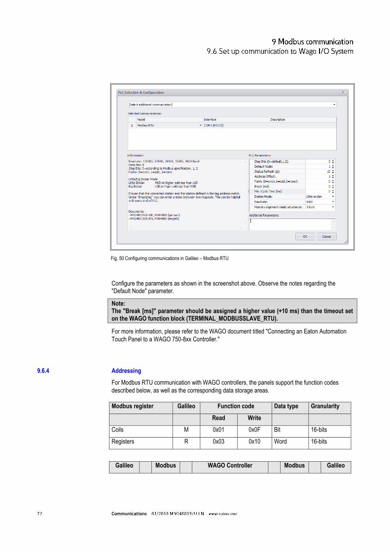
Communications
Fig. 50 Configuring communications in Galileo – Modbus RTU
Configure the parameters as shown in the screenshot above. Observe the notes regarding the "Default Node" parameter.
Note: The "Break [ms]" parameter should be assigned a higher value (+10 ms) than the timeout set on the WAGO function block (TERMINAL_MODBUSSLAVE_RTU).
For more information, please refer to the WAGO document titled "Connecting an Eaton Automation
Touch Panel to a WAGO 750-8xx Controller."
9.6.4 Addressing
For Modbus RTU communication with WAGO controllers, the panels support the function codes
described below, as well as the corresponding data storage areas.
Modbus register Galileo Function code Data type Granularity
Read Write
Coils M 0x01 0x0F Bit 16-bits
Registers R 0x03 0x10 Word 16-bits
Galileo Modbus WAGO Controller Modbus Galileo

Communications
M 0x0F
aDATA[BIT_OFFSET]
0x01 M
R 0x10
aDATA[0]
0x03 R
Note: The WAGO TERMINAL_MODBUSSLAVE_RTU block defines an ARRAY for a maximum of 256 Modbus registers (aDATA).
The BIT_OFFSET parameter can be used to define the index in the ARRAY starting from which the coils are stored.
9.6.5 Fault messages
If there is a communication malfunction, one of the following system messages may be generated:
System message (Status) Possible cause
"............ CONNECTION" "............ CABLE"
There is no bus connection or the connection cable was assembled incorrectly.
"............ TIMEOUT" The PLC is sending an incomplete data stream.
"............ ADDRESS” "............ ILLEGAL DATA ADDRESS”
The requested address is not available on the PLC.
"............ STATION” The response was not generated by the addressed PLC.
"............ PROTOCOL” "............ ILLEGAL FUNCTION”
The PLC's response does not conform to the Modbus RTU specification, or the Modbus function (function code) is not available.
"............ CHECKSUM?” The data packet's checksum is incorrect.

Communications
10 ELC (Eaton Logic Controller) communication
10.1 Function principle
This communication method uses the Modbus protocol (ASCII and RTU for the RS232 and RS485
ports, as well as Modbus/TCP over Ethernet). Communication takes place between a panel, or a PC,
and exactly one "controller" via RS232, RS485, or Ethernet.
The front connector is an RS232 interface.
The connector at the bottom of the device is an RS485 interface.
Fig. 51 How it works with panels
Fig. 52 How it works with PCs

Communications
10.2 Communication parameters
The baud rate settings for the client and the controller must be identical.
The client uses node address 0.
Configure the controller's RS232 or RS485 port as follows:
Node address: Can be specified using the communication parameters
System Mode
Modbus (ASCII / RTU / TCP)
7 Data Bits, Even Parity, 1 Stop Bit (= Modbus ASCII)
8 Data Bits, Even Parity, 1 Stop Bit (= Modbus RTU/TCP)
No Handshaking
BCC or CRC Error Detection
1000 ms ACK Timeout
10.2.1 Supported systems
10.2.1.1 Client
The following devices can communicate with ELCs (Eaton Logic Controllers):
PC with Galileo Open and RS232 or RS485 interface
XV series panel with RS232 or RS485 interface
XC series panel with RS232 or RS485 interface
Starting here, the term client will be used in order to refer to these devices and the software running
on them.
10.2.1.2 Server:
All ELC controllers are supported:
ELC PV (the highest category that has been tested)
Starting here, the term controller will be used in order to refer to all ELC devices.

Communications
10.3 Supported data
10.3.1 Addresses
Designation Address range Data Type
S 0 … 1023 Bit
X 0 … 377 oct (z.B. 0…7, 10…17) Bit
Y 0 … 377 oct Bit
T 0 … 255 Bit / Word
M 0 … 4095 Bit
Cc 0 … 255 Bit / Word
D 0 … 9999 Word
Tab. 21 Supported addresses
10.4 Cable assembly and termination
Pin assignment for the RS232 programming interface on the controller.
Fig. 53 Pin assignment for the port on the controller
Pin No. Designation
1 +5 V
2 +5 V
3 GND
4 Rx
5 Tx
6 GND
7 NC
8 GND
Tab. 22 Pin assignment for the port on the controller

Communications
RS232 cable dimensions.
Fig. 54 RS232 cable
PC/HMI COM port
9-pin female D-sub
ELC COM1 Port
8 Pin MINI DIN
Tab. 23 Pin assignment for RS232 plug
Both the client and the controller feature an RS232 and/or RS485 port and can be connected using
this port.
10.5 Set up communication to ELC device
The Galileo visualization program supports the use of multiple parallel communication channels. One
controller will take up one serial interface exclusively.
Galileo defines 6 ELC communications: ELC generic ASCII, ELC generic RTU, ELC generic TCP,
ELC-PV ASCII, ELC-PV RTU and ELC-PV TCP. The suffix ASCII, RTU and TCP defines the
MODBUS transport protocol to be used. The communications which have a name starting with ELC-
PV should be used to communicate with ELC-PV and ELC2-PV devices. The communications
containing the term generic in the name should be used to communicate with all other ELC flavours
(ELC-PB, ELC-PA, ELC-PC, ELC-PH, ELC2-PB, ELC2-PA, ELC2-PC).
The communication parameters between the ELC generic and ELC-PV communications for the same
MODBUS protocol, e.g. for ELC generic RTU and ELC-PV RTU, are the same. Therefore in the
following subsections only one communication for each MODBUS transport protocol is discussed.
10.5.1 Setting up ELC generic ASCII and ELC-PV ASCII communications
Depending on your device select either ELC generic ASCII or ELC-PV ASCII as communication and
configure the communication parameters as required. The following image shows an example of the
configuration dialogue for the ELC-PV ASCII communication.

Communications
Fig. 55 Configuring communications in Galileo – ELC-PV ASCII
Communication parameters Comment
Stopbits (0=standard,1,2): Select the right stop bits for your controller. If "0=default" is selected: The stop bit will be automatically selected as per the Modbus standard based on the selected parity.
Parity Stop bit
Flat 1
odd 1
None 2
Default Node: Enter the station number for the default PLC here.
Status Refresh [s]: For more information, read the online help for your Galileo version.
Parity: (0=even, 1=odd, 2=none) Select the right parity for your PLC. The default for Modbus RTU is 0 (even parity).
Break [ms]: Can be used to define a pause generated after an active data transfer with the PLC.
7/8 Bit Mode: Number of data bits per character
Min. Cycle Time:
Endian Mode: This parameter defines how data is organized in the protocol.
Baud Rate: The baud rates for the client and controller must be identical.
Memory alignment inside 1 Byte, 2 Byte (Word), 4 Byte (DWord)

Communications
structures:
Tab. 24 ELC generic ASCII and ELC-PV ASCII communication parameters
10.5.2 Setting up ELC generic RTU and ELC-PV RTU communications
Depending on your device select either ELC generic RTU or ELC-PV RTU as communication and
configure the communication parameters as required. The following image shows an example of the
configuration dialogue for the ELC-PV RTU communication.
Fig. 56 Configuring communications in Galileo – ELC-PV RTU
Communication parameters Comment
Stop Bits (0=default,1,2): Select the right stop bits for your controller. If "0=default" is selected: The stop bit will be automatically selected as per the Modbus standard based on the selected parity.
Parity Stop bit
Flat 1
odd 1
None 2
Default Node: Enter the station number for the default PLC here.

Communications
Status Refresh [s]: For more information, read the online help for your Galileo version.
Parity: (0=even, 1=odd, 2=none) Select the right parity for your PLC. The default for Modbus RTU is 0 (even parity).
Break [ms]: Can be used to define a pause generated after an active data transfer with the PLC.
Min. Cycle Time:
Endian Mode: This parameter defines how data is organized in the protocol.
Baud Rate: The baud rates for the client and controller must be identical.
Memory alignment inside structures:
1 Byte, 2 Byte (Word), 4 Byte (DWord)
Tab. 25 ELC generic RTU and ELC-PV RTU communication parameters

Communications
10.5.3 Setting up ELC generic TCP and ELC-PV TCP communications
Depending on your device select either ELC generic TCP or ELC-PV TCP as communication and
configure the communication parameters as required. The following image shows an example of the
configuration dialogue for the ELC-PV TCP communication.
Fig. 57 Configuring communications in Galileo – ELC-PV TCP
Communication parameters Comment
Standard Unit Identifier: Required in order to communicate with target units located behind bridges, routers, or gateways addressed with a single IP address. The "Unit Identifier" identifies the target unit.
Status Refresh [s]: For more information, read the online help for your Galileo version.
Port number Default port number
Break [ms]: Can be used to define a pause generated after an active data transfer with the PLC.
Startup Delay [s] For more information, read the online help for your Galileo version.
IP Address or Hostname: IP address or hostname Example: 172.17.103.5
Min. Cycle Time:
Endian Mode: This parameter defines how data is organized in the protocol.

Communications
Memory alignment inside structures:
1 Byte, 2 Byte (Word), 4 Byte (DWord)
Tab. 26 ELC generic TCP and ELC-PV TCP communication parameters
10.5.4 Assigning addresses to tags
Galileo supports the following address formats and data types:
Galileo Controller
C%d D%d M%d S%d T%d X%o Y%o
Tags on the controller.
Tab. 27 Address formats in Galileo
Galileo Controller
Bit / Error C, M, S, T, X, Y
Byte: not supported
Word C, D, T
DWord Cc
Float not supported
String not supported
Structure not supported
Tab. 28 Data types in Galileo

Communications
11 SIMATIC S7 communication
11.1 Function principle
This documentation describes the following three communication options:
Siemens – MPI for panels with an MPI/DP interface.
Siemens – Industrial Ethernet for panels with an Ethernet interface.
Siemens – S7 Profibus Standard Profile for panels with an MPI/DP interface.
11.1.1 Panel on MPI/PROFIBUS-DP network
The connection to the SIMATIC S7 is made either directly via the CPU's programming port (MPI) or
via a PROFIBUS port (CPU or CP) that supports S7 communication. In this regard, no function blocks
need to be enabled and, in the case of MPI, no parameters need to be configured. As soon as the
panel is connected to the network, it will be shown with the configured node number in the PG, under
"Accessible Nodes." However, you will not be able to establish a connection to the node with the PG.
If you attempt to establish a connection anyway, the panel will reject the connection and the PG will
show a prompt saying "User refuses connection setup."
The panel can establish an active connection to a maximum of 42 nodes (SIMATIC S7 PLCs)
simultaneously.
Note: SIMATIC PLCs only support a limited number of connections. Each panel will take up at least one OP connection.
Fig. 58 How the panel works on an MPI/PROFIBUS-DP network

Communications
The following are the default settings for the addresses in the MPI network:
MPI address 0 is reserved for the SIMATIC PG.
MPI address 1 is the default setting for an Operator Panel (MMI)
MPI address 2 is the default setting for a PLC
MPI addresses 3 to HSA (highest station address) are freely available
11.1.2 Panel on Industrial Ethernet network
The connection to the SIMATIC S7 is made directly using the CPU's or CP's Ethernet port. In this regard, no additional parameters need to be configured and no function blocks need to be enabled. Another option is to use a gateway (router) to communicate with other PLCs on the MPI/PROFIBUS-DP network. In order to use this option, one of the nodes on the Ethernet network must take over the router function. A SIMATIC S7 station with an Ethernet interface and an MPI/PROFIBUS interface or a panel with an Ethernet port and an MPI interface can be used as a router.
For information on how to use a panel as a router, please refer to the "S7 PG Router" user manual.
The panel can establish a connection to multiple nodes (SIMATIC S7 PLCs) simultaneously.
Note: SIMATIC PLCs only support a limited number of connections. Each panel will take up at least one OP connection.
Fig. 59 How the panel works on an Industrial Ethernet network

Communications
Note: The station and IP addresses shown above are examples. What is important is for each individual node to be assigned its own unique station and/or IP address.
11.2 Communication parameters
11.2.1 Addresses
Addresses are assigned based on SIMATIC syntax conventions. All common data types are
supported.
Address syntax without station number Data Block
AB %d.%d Out
EB %d.%d input
MB %d.%d Marker
DB %d.DBX %d.%d
Data access in data function block DB %d.DBB %d
DB %d.DBW %d
DB %d.DBD %d
Tab. 29 Supported addresses without station number
Address syntax with station number Data Block
ST %d:AB %d.%d Out
ST %d:EB %d.%d input
ST %d:MB %d.%d Marker
ST %d:DB %d.DBX %d.%d
Data access in data function block ST %d:DB %d.DBB %d
ST %d:DB %d.DBW %d
ST %d:DB %d.DBD %d
Tab. 30 Supported addresses with station number

Communications
Wildcard %d stands for a decimal number that must be entered when setting the addresses for the
individual tags. ST stands for the station number on the MPI/PROFIBUS network. If a station number
is not specified when assigning addresses, the default station number from the "PLC Selection and
Configuration" dialog box will be used.
Fig. 60 PLC Selection & Configuration – Station number 2
If a station number is specified when assigning the tag's address, the default station number from the
"PLC Selection and Configuration" dialog box will not be used for the tag.

Communications
Fig. 61 Setting an address – DB10_DBB10
11.2.2 Memory alignment inside structures
Memory alignment defines how the individual tags in a structure are stored in the PLC's memory.
Within Siemens PLC’s, data function blocks are normally defined with a memory alignment of 2 bytes.
However, there are some Siemens specific variations to a standard 2 bytes alignment. Therefore for
Siemens communications in Galileo there is, besides the standard 2 and 4 bytes alignment, also an
alignment option called Siemens available. This is the default setting and should be used, if one
intends to access function blocks from within Galileo.
For more information on memory alignment, please refer to the documentation for Galileo or to the
online help for Galileo.
11.2.3 Status Refresh
For information on startup delays, please refer to the online help for Galileo.
11.2.4 Default Slot
The rack slot for the CPU to which an address is being assigned must be entered. If the network
cable is connected directly to the SIMATIC S7 CPU (MPI/DP), a value of 0 can be entered.
Rack 0 has slots 1 to 31, Rack 1 has slots 33 to 63, etc.
This setting will apply to all the stations corresponding to a connection.

Communications
Fig. 62 PLC Selection & Configuration – Default slot 2
11.3 Importing tags
The following file formats are supported:
Siemens Step7 – Symbol table (*.seq) und DB (*awl)
Siemens TIA – Symbol table (*.xlsx) und DB (*.awl)
Note: Make sure that the selected memory alignment is Siemens before you start a tag import.
Since sometimes not all addresses of data function blocks are known during import, the missing DB
numbers must be specified in the second import step.

Communications
Fig. 63 Specifying DB numbers
11.3.1 Data Type
Time data types are imported as follows:
Data type Comment
S5TIME S5TIME is mapped to DWORD on the client.
TIME TIME is mapped to DWORD on the client.
DATE DATE is mapped to DWORD on the client.
TIME_OF_DAY TIME_OF_DAY is mapped to DWORD on the client.
DATE_AND_TIME DATE_AND_TIME is mapped to a structure of 8 byte size.
DTL DTL is mapped to a structure of 12 byte size.
Tab. 31 Supported time data types
The following data types are not supported as of this writing: LTIME LTIME_OF_DAY LDT LWORD LINT ULINT LREAL

Communications
11.3.2 User-defined types
Importing user-defined types is not supported. Instances of user-defined types are imported as
structures
11.3.3 Marker bits
Since it is not possible in Galileo to address bit variables individually, marker bits are combined into
arrays of eight bits.
11.3.4 Arrays
Multi-dimensional arrays of primitive data types must be declared as several single-dimensional
arrays. The higher dimensional indices are added comma separated in brackets to the variable name.
Fig. 64 Data function bloc with a two-dimensional array (AWL) Fig. 65 Data function bloc with a two-dimensional array in Galileo
One or more dimensional arrays of strings must be declared as single elements. The indices are
added comma separated in brackets to the variable name.
Fig. 66 Data function bloc with an array of strings (AWL) Fig. 67 Data function bloc with an array of strings in Galileo
Arrays of structures are not supported.

Communications
11.3.5 Reimport
Existing In, Out and Marker tags are merged with the existing tags based on their addresses. Data
function blocks are address-based merged as well.
All elements of a data function block are merged using their names instead of their addresses.
11.4 Set up communication to SIMATIC S7 device
This communication method requires a panel with an MPI interface. For information on the
communication cable, please consult the PROFIBUS section in the "Installation Instructions, General
Wiring Information" document.
Regardless of the number of connections, there must be 40 available license points on the device.
Note: If you have any questions concerning license products, please contact your panel distributor.
11.4.1 Setting up communication – Siemens MPI
To be able to use Industrial Ethernet, you will need at least one of the following SIMATIC Manager
versions:
STEP 7 V5.2 + NET driver
STEP 7 V5.3
For more information on how to set up and configure a SIMATIC network, please refer to the help for
SIMATIC Manager / SIMATIC NetPro.
Note: Before creating a connection to a panel on a SIMATIC S7 PLC, make sure that the SIMATIC S7 PLC can be reached on the network with the SIMATIC PG.
11.4.1.1 Hardware requirements
This communication method requires a panel with an Ethernet interface.
For information on the communication cable, please consult the Ethernet section in the "Installation
Instructions, General Wiring Information" document.
Regardless of the number of connections, there must be 40 available license points on the device.
Note: If you have any questions concerning license products, please contact your panel distributor.
Select "Siemens – MPI" and configure the communication parameters as required.

Communications
Fig. 68 Configuring communications in Galileo –Siemens MPI
Note: Galileo supports multiple connections for the interface, i.e., multiple connections can be configured for the same interface. This means that the tags (including the corresponding system structures) on multiple PLCs can be assigned addresses. The baud rate, MMI station number, and HSA for all connections must match.
Select "Siemens – MPI" in the "PLC Selection and Configuration" dialog box. The dialog box shown
above will appear so that you can configure the parameters required for the corresponding
communication method.
11.4.1.2 Baud Rate
187.5 kB and 1.5 MB are supported. The baud rate must match the baud rate setting for the MPI
subnet in STEP 7 SIMATIC Manager.
11.4.1.3 MMI Station No.
The panel's station number on the MPI network. The number must fall within a range of 1 to HSA.
Moreover, it is necessary to make sure that every node on the MPI subnet is assigned a unique MPI
address. If necessary, check the information in "Accessible Nodes" using the SIMATIC PG to check
which addresses have been assigned already.

Communications
11.4.1.4 Highest Station Address (HSA)
The setting specifying the highest MPI address is used to optimize the MPI subnet. This setting must
match the setting for the highest MPI address on the MPI subnet in STEP 7 SIMATIC Manager. The
following values are valid: 15, 31, 63, and 126.
11.4.2 Setting up communication – Siemens Industrial Ethernet
Select "Siemens – Industrial Ethernet" and configure the communication parameters as required.
Fig. 69 Configuring communications in Galileo –Siemens Industrial Ethernet
Note: Galileo supports multiple connections for the Ethernet interface, i.e., multiple connections can be configured for the same port. This means that the tags (including the corresponding system structures) on multiple PLCs can be assigned addresses.
Select "Siemens – Industrial Ethernet" in the "PLC Selection and Configuration" dialog box. The
dialog box shown above will appear so that you can configure the parameters required for the
corresponding communication method.
11.4.3 Startup Delay
For information on startup delays, please refer to the online help for Galileo.

Communications
11.4.4 MPI/PROFIBUS Station No.
Used to enter the station number of the node defined as a router on the MPI/PROFIBUS subnet. This
node can be a panel or a SIMATIC S7 station.
In the following example, in which communication takes place via a SIMATIC S7 station used as a
router, station number 31 would be entered for communication with stations 2 and 31.
Fig. 70 Station numbers – Stations 2 and 31
In the following example, in which communication takes place via a panel used as a router, station
number 31 would be entered for communication with station 2.

Communications
Fig. 71 Station numbers – Station 2 and panel 31
In the following example, in which a PLC is connected directly to the Ethernet network, 5 would be
entered for communication with station number 5.
Fig. 72 Station number – Station 5

Communications
11.4.5 MPI/PROFIBUS S7-Subnet-ID
An MPI/PROFIBUS S7 subnet ID only needs to be entered if a PLC on the MPI/PROFIBUS subnet is
being accessed via a router. In the following example, this would be required for station number 2. A
subnet ID does not have to be entered if the PLC can be accessed directly via the Ethernet network.
The MPI/PROFIBUS S7 subnet ID must be taken from the SIMATIC network configuration, and
should not be confused with the Ethernet S7 subnet ID.
Fig. 73 MPI/PROFIBUS S7 – Subnet ID
11.4.6 IP Address
The IP address must match the setting for the SIMATIC station or panel with the PG router function. This setting will be the router's / node's IP address on the Ethernet network.
In the following example, two connections would need to be configured:
1. 192.168.0.39 would be entered for the connection to station numbers 2 and 31.
2. 192.168.0.40 would be entered for the connection to station number 5.

Communications
Fig. 74 IP Address
Fig. 75 Industrial Ethernet – IP address
Note: The subnet mask for the panel must match the subnet mask for the SIMATIC S7 station. For more information on how to set the panel's IP address, please refer to "Windows CE System Description."

Communications
11.5 Setting up communication to – Siemens – S7 Profibus Standard Profile
11.5.1 General
To be able to use this communication method, you will need a SIMATIC CPU/CP that supports S7
communication at least as a slave via PROFIBUS.
A panel will take up at least one OP connection.
For more information on how to set up and configure a SIMATIC network, please refer to the help for
SIMATIC Manager / SIMATIC NetPro.
11.5.2 Hardware requirements
This communication method requires a panel with an MPI/DP interface. For information on the
communication cable, please consult the PROFIBUS section in the "System Description – Networks
in Brief" document.
Regardless of the number of connections, there must be 40 available license points on the device.
Note: If you have any questions concerning license products, please contact your panel distributor.
11.5.3 SIMATIC network settings
The standard profile must be selected under "Profile." When using this profile, the "Options..." button
can be used to take into account additional nodes, that cannot be configured with STEP 7, when
calculating the relevant bus parameters.
Note: If you cannot run the PROFIBUS bus with the bus parameters for the standard profile, please contact our Support staff.

Communications
Fig. 76 MPI Profibus – Network settings
Exactly one active node with an S7 communication load must be added for each panel. The
percentage of the total bus load must be selected as "low."
11.5.4 Setting up communication – Siemens S7 Profibus Standard Profile
Fig. 77 PLC Selection and Configuration - Siemens S7 Profibus Standard Profile
Note: Galileo supports multiple connections for the interface, i.e., multiple connections can be configured for the same interface. This means that the tags (including the corresponding system structures) on multiple PLCs can be assigned addresses. The baud rate, MMI station number, and HSA, and TTR for all connections must match.
Select "Siemens – 7 Profibus Standard Profile" in the "PLC Selection and Configuration" dialog box.
The dialog box shown above will appear so that you can configure the parameters required for the
corresponding communication method.
11.5.4.1 Baud Rate
9.6 kbit/s, 19.2 kbit/s, 45.45 kbit/s, 93.75 kbit/s, 187.5 kbit/s, 500 kbit/s and 1.5 Mbit/s are supported
for XV100 and XV300 devices. In addition also the baud rates 3, 6 and 12 Mbit/s are supported for

Communications
XV300 devices. The baud rate must match the baud rate setting for the PROFIBUS network in STEP
7 SIMATIC Manager.
The 45.45 kB baud rate is intended for segment couplers and links to PROFIBUS-PA.
11.5.4.2 Station Number
The panel's station number on the PROFIBUS network. The number must fall within a range of 1 to
HSA. Moreover, it is necessary to make sure that every node on the PROFIBUS subnet is assigned a
unique PROFIBUS address.
11.5.4.3 Highest Station Address (HAS)
The setting specifying the highest PROFIBUS address is used to optimize the PROFIBUS subnet.
This setting must match the setting for the highest PROFIBUS address on the PROFIBUS subnet in
STEP 7 SIMATIC Manager. The following values are valid: 15, 31, 63, and 126.
11.5.4.4 Target Rotation Time (TTR)
The TTR in t_Bit is calculated in the STEP 7 network configuration and must be copied accordingly.
Please note that changes to the SIMATIC network settings may affect the TTR.
11.5.4.5 Additional Parameters
Further bus parameters can be set in the “Additional Parameters” field. This field requires the
parameters to be specified as a name value pair, separated by an equal sign
<name>=<value>
without any spaces between the <name>, the <value> and the equal sign. Each line contains exactly
one entry.
The available parameters are listed in Error! Reference source not found.. The “Parameter Name”
in the table identifies the <name> in a name value entry.
The
Parameter Name Description
TSL Slot time [tBit] The maximal time in units of tBit a master waits for answer from a slave.
MinTSDR Minimum Station Delay of Responders [tBit] The minimal time in units of tBit the slave has to wait before sending an answer.
MaxTSDR Maximum Station Delay of Responders [tBit] The maximal time in units of tBit the slave is allowed to wait before sending an answer.
TQUI Quiet time [tBit] Time in units of tBit required after a transmission to change from sending to receiving state.
TSET Setup time [tBit] Time duration in units of tBit after switching to transmission mode before sending of data can begin.
GapUpdateFactor Gap update factor [token rotations]
MaxRetryLimit Maximal number of transmission retries

Communications
Tab. 32 Additional parameters for Siemens S7 Profibus Standard Profile communication. tBit refers to the time duration
required to transmit a single bit.
11.5.5 Fault messages
If there is a communication error, a variety of system fault messages may be generated. In turn,
these system fault messages provide a variety of information:
The address, followed by the block size in bytes, specifies the tag or tag blocks on which the error has occurred.
The communication name corresponds to the "Description" field in the "PLC Selection and Configuration" dialog box, and is used to identify the communication channel on which a problem has occurred.
The station number after ST is the MPI address for the affected PLC (CPU).
The additional information may point out a potential error cause using cleartext. However, this information may also be generated by deeper software layers. In other words, users who are not extensively familiar with the system may not be able to always interpret the contents of this additional information. Regardless, the troubleshooting procedure will remain the same in all cases.
Fig. 78 SIMATIC S7 - Fault messages
11.5.6 Bug Fix
We recommend checking the following:
Check the wiring and connections on the panel and PLC.
Active Station activation flag. 0 means turned off, 1 means active.
Optimize Parameter to optimize the communication behavior. The parameter must be specified as an integer. Each bit in the integer turns on or off a certain feature. Bit 0: If turned on, constant time for “SC confirmation” Bit 1: If turned on, constant time for “no reply on indication”

Communications
Check the baud rate, HSA, and TTR settings. These settings must be the same for all nodes. Check all other parameters in the "PLC Selection..." dialog box.
Check the MPI/PROFIBUS addresses on the network. Is the station number shown in the system error message present and reachable on the MPI/PROFIBUS network? Each address must only be found once on the network.
Does the address for the tag shown in the system fault message exist in the corresponding station? (Has the corresponding DB been created?)
Are Ethernet communications overloaded?
Can the PLC (CPU) be reached with the SIMATIC PG?
Can the PLC (CPU) be reached with a ping command via Ethernet?
If the problem continues, please contact our Customer Support staff at [email protected].

Communications
12 SIMATIC S7 / 200 PPI communication
12.1 Function principle
This documentation describes the following three communication options:
Siemens – PPI for panels with a PROFIBUS interface.
This communication method requires a panel with a PROFIBUS interface.
For information on the communication cable, please consult the PROFIBUS section in the "Installation Instructions, General Wiring Information" document.
Regardless of the number of connections, there must be 40 available license points on the device.
Note: If you have any questions concerning license products, please contact your panel distributor.
12.1.1 Panel on PROFIBUS network
The connection to the SIMATIC S7-200 is made directly via the CPU's programming port (PPI) that
supports the PPI protocol. In this regard, no function blocks need to be enabled. As soon as the panel
is connected to the network, it will be shown with the configured node number in the PG, under
"Communication." However, you will not be able to establish a connection to the node with the PG.
The panel will be shown as "UNKNOWN address: n".
The panel can establish an active connection to multiple nodes (SIMATIC S7-200 PLCs)
simultaneously.
Note: Networks featuring multiple panels and S7-200 stations will be affected by various factors. The baud rate and the number of stations will have a direct impact on communications and, when the baud rates are low, may result in communication errors (timeouts).
Fig. 79 How the panel works on an MPI/PROFIBUS-DP network

Communications
The following are the default settings for the addresses on the network:
Address 0 is reserved for the SIMATIC PG.
Address 1 is the default setting for an Operator Panel (MMI)
Address 2 is the default setting for a PLC
Addresses 3 to HSA (highest station address) are freely available
Note: Both the MPI and the PPI protocols can be used on the same network, e.g., ST1 with ST2 and ST4 using PPI and ST3 with ST5 using MPI. For this to work, the baud rate and the HSA of all the stations on the network must match.
12.2 Communication parameters
12.2.1 Addresses
Addresses are assigned based on SIMATIC syntax conventions. All common data types are
supported.
Address syntax without station number Data Block
A %d.%d Output (digital)
AB %d.%d
E %d.%d Input (digital)
EB %d.%d
M %d.%d
Marker MB %d.%d
MW %d.%d
MD %d.%d
V %d.%d
Variable memory VB %d.%d
VW %d.%d
VD %d.%d
Tab. 33 Supported addresses without station number

Communications
Address syntax with station number Data Block
ST %d: A %d.%d Output (digital)
ST %d: AB %d.%d
ST %d: E %d.%d Input (digital)
ST %d: EB %d.%d
ST %d: M %d.%d
Marker ST %d: MB %d.%d
ST %d: MW %d.%d
ST %d: MD %d.%d
ST %d: V %d.%d
Variable memory ST %d: VB %d.%d
ST %d: VW %d.%d
ST %d: VD %d.%d
Tab. 34 Supported addresses with station number
Wildcard %d stands for a decimal number than must be entered when setting the addresses for the
individual tags. ST stands for the station number on the network. If a station number is not specified
when assigning addresses, the default station number from the "PLC Selection and Configuration"
dialog box will be used.
Fig. 80 PLC Selection & Configuration – Station number 2

Communications
If a station number is specified when assigning the tag's address, the default station number from the
"PLC Selection and Configuration" dialog box will not be used for the tag.
Fig. 81 Setting an address – VB136
12.2.2 Strings
There are two generations of S7-200 controllers, hereafter referred to as CPU-21x and CPU-22x. A
string tag can be declared as a "char array" and as a "STRING" type in both PLC generations. Example:
'Hello World' Char array
“Hello World“ STRING
The difference is in the single/double quotation marks.
CPU-21x controllers will store both string types as null-terminated strings in their memory.
In contrast, CPU-22x controllers will only store char array tags as null-terminated strings. STRING
variables will instead be stored as Pascal strings.
Due to these differences, STRING tags for CPU-22x controllers are not supported in Galileo.

Communications
12.2.3 Memory Alignment
Please refer to the Galileo online help.
12.3 Set up communication to SIMATIC S7 / 200 PPI device
12.3.1 Setting up communication – SIMATIC S7 / 200 PPI
Fig. 82 PLC Selection and Configuration – SIMATIC S7 / 200 PPI
12.3.1.1 Baud Rate
9.6 kB, 19.2 kB, and 187.5 kB are supported. The baud rate must match the baud rate setting for all
stations on the network.
12.3.1.2 Highest Station Address (HAS)
The setting specifying the highest station address is used to optimize the PROFIBUS network. This
setting must match the setting for the highest station address on the subnet in STEP 7-Micro/WIN in
the CPU configuration for a CPU interface. The following values are valid: 15, 31, 63, and 126.
12.3.1.3 Status Refresh
Please refer to the Galileo online help.

Communications
12.3.1.4 MMI Station No.
The panel's station number on the PROFIBUS network. The number must fall within a range of 1 to HSA. Moreover, it is necessary to make sure that every node is assigned a unique address.
If necessary, check in "Communication" on the PG to see which addresses have already been assigned.
12.3.1.5 Default Station No.
See addressing.
12.3.2 Fault messages
If there is a communication error, a variety of system fault messages may be generated. In turn,
these system fault messages provide a variety of information:
The address, followed by the block size in bytes, specifies the tag or tag blocks on which the error has occurred.
The communication name corresponds to the "Description" field in the "PLC Selection and Configuration" dialog box, and is used to identify the communication channel on which a problem has occurred.
The station number after ST is the address for the affected PLC (CPU).
The additional information may point out a potential error cause using cleartext. However, this information may also be generated by deeper software layers. In other words, users who are not extensively familiar with the system may not be able to always interpret the contents of this additional information. Regardless, the troubleshooting procedure will remain the same in all cases.
Fig. 83 SIMATIC S7 / 200 PPI - Fault messages
12.3.3 Bug Fix
We recommend checking the following:
Check the wiring and connections on the panel and PLC.
Check the baud rate and HSA settings. These settings must be identical on all nodes.

Communications
Check the station addresses on the network. Is the station number shown in the system fault message present and reachable on the PROFIBUS network? Each address must only be found once on the network.
Does the address for the tag shown in the system fault message exist in the corresponding station?
Are communications overloaded?
Can the PLC (CPU) be reached with the PG?
If the problem continues, please contact our Customer Support staff at [email protected].

Communications
13 Beckhoff TwinCAT communication
13.1 Function principle
A Beckhoff TwinCAT PLC device is connected to a computer or panel running GRS directly by
Ethernet. Communication is implemented via TCP/IP, Port 48898 (0xBF02). The basic
communication procedure is described in the Beckhoff documentation for TwinCAT ADS under
“Introduction ADS”.
Fig. 84 shows a setup connecting two panels with a Beckhoff TwinCAT device. The IP addresses and
AmsNetId’s are shown as examples. It is important that each device is assigned a unique IP address
and AmsNetId. The AmsNetIds of the panels are per default the same as the respective IP address
with the suffix “.1.1”.
The AmsNetId of the Beckhoff device can be adjust using the Beckhoff TwinCAT programming
software.
Fig. 84 Example shows how IP addresses and AmsNetId’s are addressed within a setup connecting two panels with a Beckhoff TwinCAT device over Ethernet.
13.2 Tag addressing
The address format is defined by the CODESYS syntax. The following typical address types are
supported:
<tag>
<tag>.<arrayindex>[]
<struct>.<tag>
<struct>.<tag>.<arrayindex>[]

Communications
<prog>.<tag>
<prog>.<tag>.<arrayindex>[]
<prog>.<struct>.<tag>
<prog>.<struct>.<tag>.<arrayindex>[]
The tag variables are addressed in Galileo and in the PLC via the symbolic names in accordance with
IEC61131-3.
Fig. 85 Available address formats for Beckhoff TwinCAT communication
13.3 Importing Tags
13.3.1 TwinCAT 2
Importing tags from a TwinCAT 2 project works similar to CODESYS V2 see 5.2 and 5.3.
13.3.2 TwinCAT 3
13.3.2.1 Obtaining the import file
To import tags from your existing TwinCAT3 project you first need to generate a PLCopenXML file:
1. Open your project/solution in the TwinCAT3 XAE software.
2. Right click on project you wish to export tags from as shown on the image bellow. If
you wish to export only part of the project it is possible by right-clicking directly on
DUTs, GVLs, POUs.
3. Click on the “Export PLCopenXML…” option.
4. Specify the file name and location and click on save button.

Communications
13.3.2.2 Import process
The PLCopenXML file can be used to import tags into a Beckhoff – TwinCAT communication.
Following table shows how each of the TwinCAT3 objects is imported.
TwinCAT3 Handling
Union Imported as user defined type (same as TC3 “Structure”).
Enumeration Imported as underlying type which is SINGED WORD if not defined otherwise.
Structure Imported as user defined type.
Alias Aliases are not imported. Instead the tags that in TC3 have alias as its type are imported directly as the base type of the alias. Example: TYPE message:STRING[50]; END_TYPE;
Fig. 86 Generating a PLCopenXML file in TwinCAT3 AEX software.
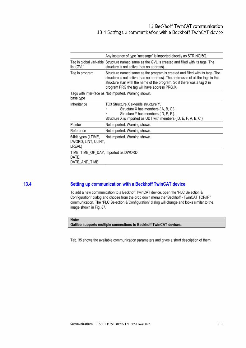
Communications
Any instance of type “message” is imported directly as STRING[50].
Tag in global vari-able list (GVL)
Structure named same as the GVL is created and filled with its tags. The structure is not active (has no address).
Tag in program Structure named same as the program is created and filled with its tags. The structure is not active (has no address). The addresses of all the tags in this structure start with the name of the program. So if there was a tag X in program PRG the tag will have address PRG.X.
Tags with inter-face as base type
Not imported. Warning shown.
Inheritance TC3 Structure X extends structure Y. • Structure X has members { A, B, C }. • Structure Y has members { D, E, F }. Structure X is imported as UDT with members { D, E, F, A, B, C }
Pointer Not imported. Warning shown.
Reference Not imported. Warning shown.
64bit types (LTIME, LWORD, LINT, ULINT, LREAL)
Not imported. Warning shown.
TIME, TIME_OF_DAY, DATE, DATE_AND_TIME
Imported as DWORD.
13.4 Setting up communication with a Beckhoff TwinCAT device
To add a new communication to a Beckhoff TwinCAT device, open the “PLC Selection &
Configuration” dialog and choose from the drop down menu the “Beckhoff - TwinCAT TCP/IP”
communication. The “PLC Selection & Configuration” dialog will change and looks similar to the
image shown in Fig. 87.
Note: Galileo supports multiple connections to Beckhoff TwinCAT devices.
Tab. 35 shows the available communication parameters and gives a short description of them.

Communications
Fig. 87 “PLC Selection & Configuration” dialog with a TwinCAT communication
PLC Parameters Comment
Status Refresh [s] For a description of this parameter, please refer to the Galileo documentation.
Port Number The TCP port used by the PLC. Default is 48898.
AMS Port Target The AMS port of the TwinCAT runtime system. The default is 801. The port 801 is per default the “PLC RuntimeSystem 1” for TwinCAT 2. However for TwinCAT 3 the “PLC RuntimeSystem 1” port is per default 851. For further information see the TwinCAT 2 documentation [1] and TwinCAT 3 documentation [2].
Startup Delay [s] For a description of this parameter, please refer to the Galileo documentation.
IP Address or Hostname The IP address or the host name of the Beckhoff TwinCAT device. Example: 192.168.0.39
AMS Net Id The AmsNetId of the Beckhoff TwinCAT device. Example: 5.0.138.27.1.1 The AmsNetId can be found in the TwinCAT System Manager. An exemplary view for the “System Manager” for TwinCAT 2 and TwinCAT 3 is shown in Fig. 88 and Fig. 89, respectively.
Endian Mode: This parameter defines how data is organized in the protocol. This communication only supports “little endian” mode.
Tab. 35 Communication parameters

Communications
Fig. 88 Find the AmsNetId for a Beckhoff device using the TwinCAT 2 System Manager
Fig. 89 Find the AmsNetId for a Beckhoff device using the TwinCAT 3 System Manager
13.5 The AmsNetId
On a TwinCAT device the exchange of data is handled via the AMS Message Router (Automation
Message Specification). This manages and distributes all messages in the system via TCP/IP
connections. TwinCAT Message Routers are provided on every TwinCAT device.
The Message Router must know the AmsNetId of its communication partner, i.e. in this case the
AmsNetId of the GRS (Galileo Runtime System) instance.
Note:
The AmsNetId of the GRS is the same as the respective IP address with the suffix “.1.1”.

Communications
13.5.1 Adding the AMS route of the panel to the Beckhoff TwinCAT device
There are basically two ways to add an AMS route to the Beckhoff TwinCAT device. Both possibilities
will be briefly explained in the next two section.
13.5.1.1 Within the TwinCAT System Manager
The AMS route to the panel can be added within the TwinCAT programming software. After choosing
the correct TwinCAT device target, one has to perform the steps as shown in Fig. 90 at the example
of the TwinCAT 3 programming software. (The steps for TwinCAT 2 are similar.)
1. Switch to the “Routes” menu.
2. Click in the “Current Routes” tab to the “Add” button.
3. Enter the routes name, the AmsNetId and IP address of the GRS (Galileo Runtime
System).
4. Click the “Add Route” button.
The entry is then transferred to the PLC.
Fig. 90 Add an AMS route to a Beckhoff TwinCAT device from withn the TwinCAT 3 System Manager

Communications
13.5.1.2 Directly on the TwinCAT device
In addition to the above described method, it is also possible to add the AMS route of the panel
directly to the Message Router on the TwinCAT device.
1. Remote connect to the TwinCAT device. E.g. by using the “CERHOST” application,
available from Beckoff [3].
2. Start the “TcAmsRemoteMgr” either by going into the directory “\Hard Disk\System” and
then click on the “TcAmsRemoteMgr” icon or by using the command line shell and type in
“TcAmsRemoteMgr”.
3. Then add the name, the AmsNetId and the IP address of the connection as shown in Fig.
91.
13.6 Galileo Open and TwinCAT
13.6.1 Operating principle
Beckhoff uses an AMS router on each device. This AMS router maintains a single connection with
each AMS router of the other devices. GRS uses AMS and therefore communicates directly with the
AMS router of the target system. On the panel this has the benefit that a router does not have to be
Fig. 91 Add an AMS route to a Beckhoff TwinCAT device from withn the device itself

Communications
installed and configured. For a PC on which the AMS router is not required, the configuration is the
same as for a panel.
The AMS router runs on every PC that is running TC 3 Workbench (TwinCAT PLC Control) or
TwinCAT PLC. Additional configuration settings are required, if GRS is used on this kind of PC. As
the AMS router on the target system (TwinCAT PLC) only supports one AmsNetId per IP address,
GRS must communicate with the AMS router via an additional AMS route. Depending on the
configuration of the installation, use the “Microsoft Loopback Adapter” or a second IP address on a
real network adapter.
13.6.2 TwinCAT PLC and GRS on the same PC
The use of Microsoft Loopback Adapter is recommended if GRS and TwinCAT PLC are installed on
the same PC. The Microsoft Loopback Adapter is a software that emulates a network card. Using the
Microsoft Loopback Adapter means that the communication between GRS and TwinCAT PLC does
not depend on the availability and function of the real network adapter or network.
In Fig. 92 a schematic diagram of an example setup is shown, illustrating the use of a loopback
adapter in addition to a physical network adapter in order to allow GRS to have its own AMSNetId,
while there is also a TwinCAT PLC running on the same machine with another AMSNetId.

Communications
13.6.2.1 Installation of the Microsoft Loopback Adapter
A description of how to install and configure the Loopback Adapter can be found in section 2.1.
13.6.2.2 Declaring the AmsNetID of GRS
Enter the AmsNetId and the IP address in TwinCAT, as described in section 13.5.1.1.
The IP address must match the setting in the network properties of the Loopback Adapter. In the
given example this is 172.16.0.151.
The AmsNetId of the GRS is the same as the respective IP address with the suffix “.1.1”. In
given example this is 172.16.0.151.1.1.
Fig. 92 Example showing a schematic view using a physical network adapter together with a loopback adapter on the same PC in order to allow GRS to have its own AMSNetId.

Communications
13.6.2.3 Selecting the PLC in Galileo
In Galileo also the IP address of the Loopback Adapter of the Beckhoff PLC must be set. The
following steps describe the required actions:
1. In the “PLC Selection & Configuration” dialog choose “Beckhoff – TwinCAT TCP/IP”
communication.
2. Enter the IP address of the Loopback Adapter. In the given example this is 172.16.0.151.
3. Enter the AmsNetId according to the settings in TwinCAT. In the given example this is
172.16.0.151.
4. Set the other communication parameters.
The dialog should look similar to the image shown in Fig. 93.
Note:
The AMSNetId must only be used once. Galileo per default uses the AmsNetId consisting of the IP address with the suffix “.1.1”. TwinCAT must not use this AmsNetId and must be reconfigured accordingly in all cases.
13.6.3 TC3 Workbench (TwinCAT PLC Control) and GRS on the same PC
If GRS and TC3 Workbench (in the TwinCAT 2 environment this was called TwinCAT PLC Control)
are installed on the same PC, GRS must use its own IP address on the network adapter. An example
is illustrated in Fig. 94.
Fig. 93 Setting the AMSNetId and the IP address

Communications
13.6.3.1 Adding a Second IP Address to the Network Adapter
Section 2.2 explains how to add a second IP address to a Network Adapter.
13.6.3.2 Define the AMSNetId used by GRS
GRS, as well as TC3 Workbench, use per default the first IP address of the adapter. For GRS this
means that the constructed AMSNetId is derived from the IP address of the first adapter with the
suffix “1.1”. In order to change this behavior the AMSNetId used by GRS can be set directly in the
“Additional Parameters” entry field in the “PLC Selection & Configuration” dialog. An example is
shown in Fig. 95.
Fig. 94 Example showing a schematic view of how to setup up the IP addresses in order to run GRS and the TC3 Workbench on the same PC.

Communications
13.6.3.3 Configuring the AMS Router of the Target System
To add an AMS route to the target system one can follow the step shown in section 13.5.1.
In the given example the parameters to be added would be 192.168.1.88.1.1 for the “AMS Net Id”
and 192.168.1.88 for the “Address” field, as illustrated in Fig. 96.
Fig. 95 Changing the AMSNetId used by GRS

Communications
.
Fig. 96 Add AMS route to GRS

Communications
14 Fault messages
Fault message
Tag name or address
Interface, protocol
Additional error information

Communications
15 Bibliography
[1] "TwinCAT 2: ADS device identification," [Online]. Available: https://infosys.beckhoff.com/english.php?content=../content/1033/tcadscommon/html/tcadscommon_identadsdevice.htm&id=.
[2] "TwinCAT 3: ADS device identification," [Online]. Available: https://infosys.beckhoff.com/english.php?content=../content/1033/tc3_adscommon/html/tcadscommon_identadsdevice.htm&id=.
[3] "Beckhoff: Remote Display," [Online]. Available: http://infosys.beckhoff.com/english.php?content=../content/1033/sw_os/html/cx1000_os_ce_remotedisplay.htm&id=.


![[EN] User Manual MS4 20190821 re12download.normanwindowcoverings.com/Document/Service...Page 01/09 Product:MS4/ PerfectTilt G4 Version:2019.8.21 User Manual(Motorized Shutters)](https://static.fdocuments.us/doc/165x107/5f0642447e708231d41717ea/en-user-manual-ms4-20190821-page-0109-productims4-perfecttilt-g4-versioni2019821.jpg)