01 E-C230 Cover1 - Transportation Research...
57
TRANSPORTATION RESEARCH Number E-C230 March 2018 Culverts and Soil–Structure Interaction Fifty Years of Change and a Twenty-Year Projection
Transcript of 01 E-C230 Cover1 - Transportation Research...

T R A N S P O R T A T I O N R E S E A R C H
Number E-C230 March 2018
Culverts and Soil–Structure
Interaction
Fifty Years of Change and a Twenty-Year Projection

TRANSPORTATION RESEARCH BOARD 2018 EXECUTIVE COMMITTEE OFFICERS Chair: Katherine F. Turnbull, Executive Associate Director and Research Scientist, Texas
A&M Transportation Institute, College Station Vice Chair: Victoria A. Arroyo, Executive Director, Georgetown Climate Center; Assistant
Dean, Centers and Institutes; and Professor and Director, Environmental Law Program, Georgetown University Law Center, Washington, D.C.
Division Chair for NRC Oversight: Susan Hanson, Distinguished University Professor Emerita, School of Geography, Clark University, Worcester, Massachusetts
Executive Director: Neil J. Pedersen, Transportation Research Board TRANSPORTATION RESEARCH BOARD 2017–2018 TECHNICAL ACTIVITIES COUNCIL Chair: Hyun-A C. Park, President, Spy Pond Partners, LLC, Arlington, Massachusetts Technical Activities Director: Ann M. Brach, Transportation Research Board David Ballard, Senior Economist, Gellman Research Associates, Inc., Jenkintown,
Pennsylvania, Aviation Group Chair Coco Briseno, Deputy Director, Planning and Modal Programs, California Department of
Transportation, Sacramento, State DOT Representative Anne Goodchild, Associate Professor, University of Washington, Seattle, Freight Systems
Group Chair George Grimes, CEO Advisor, Patriot Rail Company, Denver, Colorado, Rail Group Chair David Harkey, Director, Highway Safety Research Center, University of North Carolina,
Chapel Hill, Safety and Systems Users Group Chair Dennis Hinebaugh, Director, National Bus Rapid Transit Institute, University of South
Florida Center for Urban Transportation Research, Tampa, Public Transportation Group Chair
Bevan Kirley, Research Associate, Highway Safety Research Center, University of North Carolina, Chapel Hill, Young Members Council Chair
D. Stephen Lane, Associate Principal Research Scientist, Virginia Center for Transportation Innovation and Research, Charlottesville, Design and Construction Group Chair
Ram M. Pendyala, Professor, School of Sustainable Engineering and the Built Environment, Arizona State University, Tempe, Planning and Environment Group Chair
Joseph Schofer, Professor and Associate Dean of Engineering, McCormick School of Engineering, Northwestern University, Evanston, Illinois, Policy and Organization Group Chair
Eric Shen, Director, Southern California Gateway Office, Maritime Administration, Long Beach, California, Marine Group Chair
William Varnedoe, Partner, The Kercher Group, Raleigh, North Carolina, Operations and Preservation Group Chair
Fred R. Wagner, Partner, Venable, LLP, Washington, D.C., Legal Resources Group Chair

TRANSPORTATION RESEARCH CIRCULAR E-C230
Culverts and Soil–Structure Interaction
Fifty Years of Change and a Twenty-Year Projection
Presentations from the 93rd Annual Meeting of the Transportation Research Board
January 14, 2014 Washington, D.C.
Sponsored by Standing Committee on Subsurface Soil–Structure Interaction
March 2018
Transportation Research Board 500 Fifth Street, NW
Washington, D.C. www.TRB.org

TRANSPORTATION RESEARCH CIRCULAR E-C229 ISSN 0097-8515 The Transportation Research Board is one of seven major programs of the National Academies of Sciences, Engineering, and Medicine. The mission of the Transportation Research Board is to provide leadership in transportation innovation and progress through research and information exchange, conducted within a setting that is objective, interdisciplinary, and multimodal. The Transportation Research Board is distributing this E-Circular to make the information contained herein available for use by individual practitioners in state and local transportation agencies, researchers in academic institutions, and other members of the transportation research community. The information in this E-Circular was taken directly from the submission of the authors. This document is not a report of the National Academies of Sciences, Engineering, and Medicine.
Design and Construction Group Thomas J. Kazmierowski, Chair
Geotechnical Engineering Section
Anand Puppala, Chair
Standing Committee on Subsurface Soil–Structure Interaction Kevin White, Chair
Brent Bass
Josiah Beakley James Brennan
David Brodowshi Eric Carleton Shunyi Chen
Philip Creamer Steven Folkman James Goddard Grant Gummow
Jeffery Hite
Trygve Hoff John Hurd
Leszek Janusz Kate Kattleman John Kurdziel
Michael McGough Timothy McGrath
Antonio Miglio Alena Mikhaylova
Ian Moore Abdolreza Osouli
Miguel Pando
Lee Petersen Kelly Pulaski
Christopher Rogers Hamid Sadraie Shad Sargand John Schuler Jeffery Syar Junliang Tao Jeff Tomure Mark Webb
Kevin Williams
TRB Staff G. P. Jayaprakash, Soils, Geology and Foundations, Engineer
Michael DeCarmine, Program Officer Joanice Johnson, Associate Program Officer
Angela Christian, Program Coordinator
Timothy A. Wood, Format Editor
Transportation Research Board 500 Fifth Street NW Washington, D.C.
www.TRB.org

iii
Preface
his E-Circular was developed from presentations made during the 93rd Annual Meeting of the Transportation Research Board, in a session titled “Fifty Years of Culverts and
Soil–Structure Interaction: What Have We Learned and What Does the Future Hold?” Cecil L. Jones of Diversified Engineering Services, Inc., guided the session, which was cosponsored by the Standing Committee on Culverts and Hydraulic Structures.
From the perspective of most people, the pipe industry, and especially the culvert, storm sewer, sanitary sewer, and drainage pipe industry, is largely unchanged and unchanging. Yet the past 40 to 50 years have seen significant changes in the pipe industry in terms of materials used, structure sizes, shapes, and joint capabilities. Design methodologies have become far more sophisticated, primarily through the use of load resistance factor design (LRFD) and computer-aided design such as the finite element method (FEM). The structure of the industry itself has changed as well, with new companies coming into the marketplace, consolidation of companies, and spin-offs by larger companies of specific pipe-producing units.
Through this time, the Transportation Research Board (TRB) has played a major role, driving research through National Cooperative Highway Research Program (NCHRP) projects, and by offering a platform for the exchange of independent or industry-based research information. The TRB Standing Committees on Culverts and Hydraulic Structures and Subsurface Soil–Structure Interaction have contributed by offering a forum for open discussion of the issues involved in these industry changes. They have also produced Research Needs Statements that have led to several NCHRP projects, which are discussed in more detail in this E-Circular.
Drainage is an integral part of any transportation project, whether it is for highways, airport runways, and taxiways, or railroad rights-of-way. The roadways range from Interstate-type roadway to unpaved roads. At the state department of transportation (DOT) level, drainage accounts for anywhere from 8% to over 12% of a state DOT’s annual construction budget. In terms of annual maintenance costs, the percentages are slightly higher.
The earliest roadways in the United States were “farm-to-market” roads. (This designation is still used by some state highway departments, such as Texas, which uses the prefix “FM” in their numbering system.) These roadways were most often just native soil compacted by repeated traffic, but in some cases had gravel, or even split logs as the roadway surface. During wet periods they were often impassable. Anson Marston, when he was Dean of Engineering at Iowa State University, championed “Let’s get Iowa out of the mud” in order to improve roadway drainage and roadway performance in the state of Iowa. Marston was the first Chairman of the Highway Research Board, now TRB. Marston proposed a theory for predicting soil loads on buried rigid pipe. Under Marston, Merlin G. Spangler derived the original Iowa Formula for predicting deflection of flexible pipe. Under Spangler, Reynold K. Watkins modified and improved the original Iowa Formula. The resulting Modified Iowa Formula is widely used today. This work was published in Highway Research Board Proceedings, Vol. 37, in 1958.
T

iv
Transportation drainage includes underdrain, culverts (from driveways to large stream enclosures under roadways, runways, or railroad track), storm sewers, and stormwater treatment and detention–retention systems.
— Kevin White
Chair, Standing Committee on Subsurface Soil–Structure Interaction
EDITOR’S NOTE Due to staffing changes at TRB and an extensive editing process, this E-Circular was not published immediately after the 93rd Annual Meeting of the Transportation Research Board—the time at which the TRB Standing Committee on Subsurface Soil–Structure Interaction presented these papers contained in this document. Therefore, some institutional affiliations of the paper authors may not be current, and some of the information related to current technology about culverts and soil structure could be outdated. However, it was decided to release this E-Circular because much of the information discussed relates to an historic perspective that remains relevant and is likely to inform the field.
The views expressed in this publication are those of the authors and do not necessarily reflect the views of the TRB or the National Academies of Sciences, Engineering, and Medicine. This publication has not been subjected to the formal TRB peer-review process.

v
Contents Development of Design and Analysis Methods for Buried Culverts .........................................1
Timothy J. McGrath History of Soil–Structure Interaction Models for Buried Culverts ........................................13
Michael G. Katona Fifty Years of Culvert and Soil–Structure Interaction: European Experience .....................21
Leszek Janusz, Jan Vaslestad, and Antonio Miglio Growth of Thermoplastic Pipe Use in Transportation Applications ......................................34
Jim Goddard

1
Development of Design and Analysis Methods for Buried Culverts
TIMOTHY J. MCGRATH TJMcGrath, LLC
fter World War II, President Eisenhower proposed a nationwide road network that eventually became the U.S. Interstate Highway System. Construction of this system began
in earnest in the early 1960s and millions of culverts were eventually installed to provide cross drainage for all the streams, small rivers, and numerous other water conditions crossed by the highways.
This paper presents the development of design and analysis methods used for those culverts, spanning from about 1963 to 2013, a period that saw increased consideration of the benefit of compacted soil around a culvert providing structural support, the addition of thermoplastic and fiberglass pipes to the list of available culvert options, and increased application of computerized methods of analysis.
The improved design models take advantage of the structural support provided by the soil embedment around a culvert, which can be such a large part of the structural support that we should think of a pipe–soil system, where the pipe and soil are both considered part of the structure. To aid in the concept, advances have also been made in modeling the behavior of backfill soils. Both computer and simplified models are addressed.
A significant concern for the designer when considering using soil support is that the specified installation requirements must be achieved in the field. Achieving design compaction levels around buried pipes has long been a problem in construction. The American Association of State Highway and Transportation Officials (AASHTO) is trying to address this through post-construction inspection regimens to evaluate potential pipe performance after backfilling and before placing pavement over pipes. CULVERT DESIGN SPECIFICATIONS: 1963 TO 2013 In 1963, the Standard Specifications for Highway Bridges encompassed both design and construction in a 5 in. by 7 in. format only 345 pages long. Within these specifications were seven pages devoted to culverts and all of those seven pages were for structural plate arches. Concrete pipe was in wide use, with design methods from industry standards and plastic pipe was a thing of the future (1).
Since 1963, the Standard Specifications, which largely used allowable stress methods for design, has been replaced by the AASHTO Load Resistance Factor Design Bridge Design Specifications which designs on the basis of load and resistance factors. The 2012 LRFD Specifications requires two volumes totaling 1,661 pages for design only. The 100 or so pages on the design of concrete, metal, and plastic pipes as well as procedures for box sections, three-sided culverts, and large-span culverts demonstrates that the complexity of design for culverts has expanded significantly just as it has for bridges. Large-span culverts with spans exceeding 70 ft have been successfully designed and constructed (2).
A
2 Transportation Research Circular E-C230: Culverts and Soil–Structure Interaction
DESIGN ADVANCES: 1960s As Interstate highway construction began, metal culverts were designed largely through depth of fill tables that were based on controlling compressive thrust in the pipe wall (3) and deflection using Spangler’s Iowa formula (4) as modified by Watkins (5).At this time the structural benefit of compaction of backfill around culverts was not fully realized and the key design parameter, the modulus of soil reaction (E′) was not well defined. A value of 700 psi was recommended for design, but as described below, later research showed much higher soil stiffness was possible based on backfill type and compaction level.
Concrete pipe at this time was designed based on the work of Marston, Anderson, Schlick, et al. in the early part of the 20th century (6), and several subsequent papers. These methods were presented in the Concrete Pipe Design Manual first published in 1970 (7).
While advances have been made, and additional design criteria applied, these design methods for concrete and metal pipes are still largely applicable today. DESIGN ADVANCES: 1970s Significant advances in analysis and design models for buried culverts were made in the 1970s. These included the development of the first computer programs to model culvert–soil interactions, the first studies investigating the use of plastic pipe in highway projects, and improved soil models for design.
The concrete pipe industry undertook a long-range research program to improve their understanding of pipe–soil interaction through computer models using the FEM to model pipe and soil separately and in a way that allowed variations in soil properties in the backfill zone, such as a zone of soft soil in the hard-to-compact haunch region. Although this program did not culminate until the 1980s the seeds of understanding were germinating. At the same time the concrete pipe industry funded research that led to the development of precast reinforced concrete box sections for use in highway applications.
The most significant advances in metal culverts during this period was the development of long-span structural plate culverts. These structures eventually reached spans greater than 40 ft; however, these long spans were very flexible structures and were susceptible to significant structural movements during construction. This problem was addressed through the incorporation of structural stiffeners, either circumferential stiffeners comprised of corrugated steel plate or other steel shape, or through longitudinal stiffeners usually made of concrete that distributed construction loads along the length of the culvert and thus minimized distortion during backfilling. AASHTO construction specifications were eventually modified to require full-time inspection by a manufacturer’s representative during construction.
One of the most significant design model improvements of the 1970s was the development of a rational table of design values for the modulus of soil reaction (E′). Howard presented a table of E′ values based on back calculation from deflection measurements of a large number of field installations of flexible pipe and showed that E′ could vary from a value of 50 psi for clay soil with little compaction to 3,000 psi for densely compacted coarse-grained soils with limited fines (8) (Table 1). Although not commonly recognized, Howard’s method of back calculation likely produced somewhat conservative values of soil stiffness (E′) by incorporating

Development of Design and Analysis Methods for Buried Culverts 3
TABLE 1 Modulus of Soil Reaction Versus Soil Type and Compaction (8)
Embedment Soil Type
Modulus of Soil Reaction, E′, psi Based on Compaction Level
Dumped
Slight <85% Std.
Proctor
Moderate 85%–95% Std.
Proctor
High >95% Std.
Proctor Fine-grained soils with medium to high plasticity
No data available, consult a competent soils engineer or use E′ = 0 psi
Fine-grained soils with medium to no plasticity
50 200 400 1,000
Coarse-grained soils with fines 100 400 1,000 2,000
Coarse-grained soils with little or no fines
200 1,000 2,000 3,000
Crushed rock 1,000 3,000 Note: Howard’s table is presented briefly here. For complete details, see one of the many publications that use this information.
construction variability, i.e., the previously mentioned difficulty of achieving design compaction levels. The advent of this table greatly enhanced the use of the Spangler Iowa formula for design.
In 1974, NCHRP initiated the first AASHTO study of plastic pipe. The study investigated the structural behavior of solid and corrugated wall thermoplastics, although a large-diameter plastic pipe considered for highway use at the time was about 16 in. and corrugated high-density polyethylene (HDPE) pipes were only manufactured in diameters up to 8 in. Considerations for design criteria included hoop thrust and deflection, as had been considered by metal pipe, but also strain limits. The project investigated the applicability of the Spangler Iowa formula, with soil stiffness taken from Howard’s E′ table, to plastic pipe installations and found it to be a suitable design equation for predicting deflection. Further, although the concept was not developed until later, the design method indicated that circumferential shortening, due to the combination of low cross-sectional area and low modulus of elasticity, could be significant for corrugated pipe profiles, especially pipe manufactured with HDPE. The project final report concluded that plastic pipe was indeed a viable product for highway applications and recommended a design method (9). Soil box tests on 6-in. diameter solid wall polyvinyl chloride (PVC) and corrugated HDPE pipes indicated that the response to highway wheel loads was predictable and reasonable.
One of the most significant findings of the project was the increase in deflection variability as pipe stiffness (F/ΔY in the parallel plate test) decreased. Figure 1 shows that corrugated HDPE pipe has a higher variability than the solid wall pipes, theorized as resulting from the lower longitudinal pipe stiffness; and a low stiffness (18 psi) solid wall HDPE pipe has a reduced mean deflection due to lateral pressure during compaction deflecting the pipe upward before vertical load is added. These variations in pipe deflection with pipe stiffness can be important considerations in design. The applicability of this behavior to larger diameter pipe, while expected to be similar, has not yet been clearly demonstrated.

4 Transportation Research Circular E-C230: Culverts and Soil–Structure Interaction
FIGURE 1 Effect of pipe stiffness on deflection variability (9). Aiding in the design of pipes and culverts in the 1970s was the completion of the
computer program Culvert Analysis and Design (CANDE) (10). CANDE is capable of detailed analysis of all types and shapes of culverts and has been used in research and mainstream design. CANDE is addressed in more detail elsewhere in this E-Circular. DESIGN ADVANCES: 1980s Our understanding of culvert behavior, and subsequently our approach to culvert design, increased significantly in the 1980s.
In research for the concrete pipe industry Heger and McGrath (11–14) developed a reinforcing design method for concrete pipe-based results of hundreds of three-edge bearing tests, as well as slab and beam tests. The method provided design equations for flexure, crack control, shear, and radial tension. This reinforcing design method was used to develop the finite element computer program—Spiral Duct Manufacturers Association—that in turn led to the Standard Installation Direct Design (SIDD) method for addressing pipe–soil interaction in design of concrete pipe installations and was later incorporated into AASHTO. The key element of SIDD is captured in the Heger pressure distribution that addresses how the pressure distribution around pipe changes with backfill type and compaction (15). In particular, the Heger distribution uses a more-complex bedding distribution under the pipe to consider stiffness of the invert bedding and the quality of haunch support. The Heger pressure distribution is compared with other commonly used simplified distributions in Figure 2.

Development of Design and Analysis Methods for Buried Culverts 5
(a) (b) (c) FIGURE 2 Comparison of (a) radial, (b) uniform, and (c) Heger (SIDD)
pressure distributions on rigid pipe. The specific features of the Heger distribution are shown more clearly in Figure 3 which
plots the pressure distributions of the four standard installation types to scale. In this figure, Type 1 is the highest-quality installation and Type 4 is the lowest. The trend from Types 1 to 4 is increased pressure at the invert and decreased horizontal and vertical soil pressure in the haunch region. These changes produce a significant increase in bending moments.
One advance in culvert design funded as part of the American Concrete Pavement Association long-range research program was development of the Selig soil parameters for use with the Duncan hyperbolic elastic modulus and the Selig hyperbolic bulk modulus to model nonlinear elastic behavior of compacted backfill materials (16). The soil model incorporates known behaviors of soils such as strain hardening under confined conditions, and strain softening and failure under conditions of limited confinement. The soil properties provided by Selig represent three broad soil groups: coarse-grained soils with limited fines (called SW or Sn in some publications), coarse-grained soils with fines/fine-grained soils with sand or gravel (ML or Si), and fine-grained soils (CL, or cl). Although limited by characterizing the entire range of backfills into just three groups, these properties have become the basis for almost all AASHTO culvert design procedures.
Type 1 Type 2 Type 3 Type 4
FIGURE 3 Heger pressure distribution for standard installations.

6 Transportation Research Circular E-C230: Culverts and Soil–Structure Interaction
A key distinguishing feature about these three groups is the additional energy required to reach design compaction levels, as demonstrated by Selig (17) and presented in Figure 4. The differences between the soil groups is emphasized even further when the energy required to achieve a level of soil stiffness (higher modulus of soil reaction, E′) as shown in Table 2. This table combines the E′ values at given densities with the compaction energy required to achieve a certain density, as presented in Figure 4 to show, for example, that to achieve an E′ of 1,000 psi in a CL soil requires seven times more energy than in a SW soil. This is a significant point to remember when specifying backfill materials or setting inspection levels during construction.
During the 1980s, the corrugated HDPE industry undertook a study to confirm analysis results that indicated the pipe would shorten circumferentially under high loads due to the combination of a low cross-sectional area and the low modulus of elasticity of HDPE. This circumferential shortening would substantially reduce the hoop compressive stresses in the pipe, and subsequently increase the allowable depth of burial. This concept was indicated both by closed-form elasticity solutions (19) and finite element studies and had been applied successfully to corrugated metal pipes (CMPs) with slotted joints (20). The plastic pipe study installed a 24-in. diameter corrugated HDPE pipe under 100 ft of fill and demonstrated that the compression shortening concept was valid, as the average circumferential strain in the pipe was about 2% (21). This concept was
FIGURE 4 Energy required to compact backfill materials (17). (Note: The soil groups SW, ML, and CL each include soils that do not meet
the specific criteria of ASTM D2487 for that classification.)
TABLE 2 Energy Required to Achieve Soil Stiffness (18)
Soil Type Modulus of Soil Reaction, E′, psi
400 1,000 2,000 3,000 Coarse-grained soils with ≤12% fines (SW) ≤ 5 10 17 30 Coarse-grained soils with fines or sandy or gravelly fine-grained soils (ML)
25 33 40 >100
Fine-grained soils with low plasticity (CL) 50 70 ˃100 >100 Note: Energy expressed as a percentage of the energy required to compact soil in the standard Proctor test.
Development of Design and Analysis Methods for Buried Culverts 7
later incorporated into AASHTO Design Standards for Plastic Pipes, as discussed below. The study did demonstrate some issues with joints and resin quality which have since been resolved. DESIGN ADVANCES: 1990s AND 2000s The 1990s showed a number of improvements to design, some by developing simpler concepts to address design problems and some by research.
The SIDD design method for reinforced concrete pipe was incorporated into AASHTO, culminating over 20 years of research and development using computer modeling as well as full-scale field and laboratory tests. The advance promoted a better understanding of the soil pressures on a buried pipe, but also correlated the backfill conditions with up-to-date terminology, using American Society for Testing and Materials (ASTM) and AASHTO soil classifications (ASTM D2487 and AASHTO M145, respectively) and results of Proctor density tests (e.g., AASHTO T99) for monitoring compaction. This compared with the traditional beddings which classified soils with vague terms such as gravel, sand, clay, etc. The result of this is a design and installation system compatible with modern specifications.
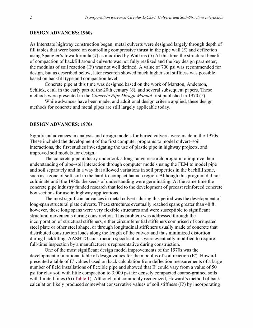
The design of flexible plastic pipes is heavily dependent on controlling deflection. Thus the values of E′, a key parameter in the Spangler deflection equation, are of keen interest to designers. McGrath studied the Selig–Duncan soil model with the Selig soil parameters, both discussed above, to understand the relationship between theoretical stress dependent models and the simplified parameters proposed by Howard (22, 23). McGrath demonstrated that the one-dimensional soil modulus (Ms), also called the constrained soil modulus, calculated using the Selig parameters, showed a close correlation with the Howard values for E′ at moderate depths of fill, which are the depths at which most of Howard’s data was collected. This suggested that E′, a highly empirical parameter, could be represented by Ms in design and, further, that designs could be completed with either the Howard values or a table of Ms values proposed by McGrath. The chief benefit of the McGrath table, which was adopted by AASHTO, is increased soil stiffness at increased depths of fill. This is shown in Table 3 which presents Ms values for a SW soil at 95% of maximum standard Proctor density.
In response to concerns about the quality of HDPE materials used in corrugated pipe, NCHRP funded a project to evaluate slow crack-growth resistance of these materials (24). While the importance of slow crack growth had long been acknowledged for pressure pipe resins, the
TABLE 3 Constrained Modulus Based on Stress Level
Soil Stress level (psi) SW-95 (psi) 1 2,000 5 2,600 10 3,000 20 3,450 40 4,250 60 5,000
Note: Howard E′ for SW soil at 95% density is 3,000 psi.

8 Transportation Research Circular E-C230: Culverts and Soil–Structure Interaction
need for requirements for nonpressure-rated resins was disputed. Hsuan and McGrath conducted a study consisting of sampling in service pipes, some of which had cracked and others not, and then testing the slow crack-growth resistance of these as well as many samples of virgin pipe materials (24). The test chosen to evaluate the slow crack-growth resistance of HDPE resins was the notched constant tensile (NCTL) test that was previously developed for HDPE membranes use in buried applications. The study also concluded that the test should be conducted on finished pipe to assure that resin quality and manufacturing variables were considered. AASHTO adopted the project recommendations into the LRFD Bridge Specifications in 2003 (25).
In other research and development activity related to HDPE, McGrath developed a simplified equation to predict thrust loads on pipe that considered the circumferential shortening previously demonstrated in the HDPE deep burial project (26). This equation developed an equation to compute the compressive force in a pipe in terms of the vertical arching factor (VAF) which is the ratio of the actual force in the pipe to the force that would result from the soil prism load (weight of soil directly over the pipe). The key parameter in this equation is the ratio of the soil stiffness (Ms) to the hoop stiffness of the pipe (EA/R). The general concept of reduced VAF versus hoop stiffness is shown in Figure 5. At almost the same time, NCHRP funded a study to develop a design procedure to evaluate the resistance to local buckling of corrugated thermoplastic pipe profiles (27, 28). This study addressed the issue of thin elements in profile wall sections that would buckle prior to developing full-compression stress. The work of Winter on light gage metal sections which considered the width thickness ratio of these elements was applied to develop a design method.
A key outcome of the work on local buckling and hoop compression forces on HDPE pipe was that corrugated pipes that have low cross-sectional area were typically controlled by compression behavior and not tension, as had been assumed by most designers. This was demonstrated by Schafer and McGrath who looked at failure envelopes under combined thrust and bending (29) (as shown in Figure 6). This work indicated that if corrugated HDPE pipe were installed in accordance with design installation practices tension stresses should rarely be a controlling factor.
FIGURE 5 VAF (load) versus hoop stiffness ratio (26).

Development of Design and Analysis Methods for Buried Culverts 9
FIGURE 6 Moment failure envelope for corrugated HDPE pipe. Since the turn of the century, developments continued for all types of pipes. Design
advances are created in part by development of new products and in part by development of increased knowledge of material properties. Thus representative of both types of advances are mentioned here.
HDPE research continued with refinements to the slow crack-growth requirements for resins and a desire by some states to establish 100-year service life for all culverts (30). Further work that investigates the properties of recycled resins for use in pipe was published by Thomas and Cuttino (31) and NCHRP Project 04-39 was initiated to further advance the work.
The metal pipe industry developed and implemented deep corrugation profiles (6 and 9 in. deep) to allow construction of long spans without the flexibility issues during construction that were related to use of the 6-x-2–in. corrugation.
Composite metal–thermoplastic pipe were introduced into the market taking advantage of the high material strength and stiffness of steel and the durability of polyethylene (PE).
Fiberglass pipe, a product that has been available for many years, was incorporated into the AASHTO LRFD Bridge Specifications.
Concrete pipe manufactured with steel fibers and thinner walls is being tested and installed.
To acknowledge that culverts often require different design treatment than bridges, AASHTO developed new design equations to calculate live loads on pipe as shown in NCHRP Report 647: Recommended Design Specifications for Live Load Distribution to Buried

10 Transportation Research Circular E-C230: Culverts and Soil–Structure Interaction
Structures (32) and initiated NCHRP Project 15-54, “Proposed Modifications to AASHTO Culvert Load Rating Specifications” to evaluate procedures for load rating culverts. KEY ELEMENTS IN DESIGN AND SUGGESTIONS MOVING FORWARD Since the inception of the U.S. Interstate Highway System, many design and material issues have been investigated, and many improvements made. The key elements to long-term success of future culvert installations require continued attention to these past findings and could be further enhanced by additional developments. A few suggestions based on the authors’ experience include the following:
• A strong emphasis on meeting design installation conditions in the field. The one recurring theme of culvert behavior and performance that keeps arising is the importance of providing proper soil support to the pipe. Achieving proper installation has proved difficult due to lack of education of contractors on key issues, the pressures on contractors to work fast to provide competitive prices, and the cost of full-time inspection to monitor actual installation. Current efforts by AASHTO are focused on detailed post-construction inspections to identify installation deficiencies immediately after construction and prior to placing pavement.
• Historically, water tightness of culvert joints has not been emphasized. Joint requirements were often stated in terms of being silt tight, on the assumption that water flowing into a pipe would not be detrimental if the backfill were not disrupted by loss of soil. However, increased environmental concerns, and increasing knowledge of the damage that can be caused by exfiltrating water have resulted in an increased emphasis on watertight joints. Agencies are increasingly specifying such joints and AASHTO materials committees are developing standards to better define joint requirements and to make requirements uniform across all types of culvert materials.
Culverts have developed substantially over the 50 years of the Interstate Highway System. Much attention needs to be paid to culverts due to the large numbers installed and their importance to long-term durability of our highways. Although not as directly related to life safety as bridges, culverts are every bit as important to roadway performance, and thus commerce and our American lifestyle, as bridges.
REFERENCES 1. AASHO. Standard Specifications for Highway Bridges. American Association of State Highway
Officials, 1961. 2. AASHTO. AASHTO LRFD Bridge Design Specifications, Customary U.S. Units. American
Association of State Highway and Transportation Officials, 2012. 3. White, H. L., and J. P. Layer. The Corrugated Metal Conduit as a Compression Ring. Highway
Research Board Proceeding, Vol. 39, 1960, pp. 389–397. 4. Spangler, M. G. The Structural Design of Flexible Pipe Culverts. Iowa State College of Agriculture
and Mechanic Arts, Ames, 1941. 5. Watkins, R. K., and M. G. Spangler. Some Characteristics of the Modulus of Passive Resistance of
Soil: A Study in Simultude. Highway Research Board Proceedings, Vol. 37, 1958, pp. 576–583.

Development of Design and Analysis Methods for Buried Culverts 11
6. Marston, A., and A. O. Anderson. The Theory of Loads on Pipes in Ditches and Tests of Cement and Clay Drain Tile and Sewer Pipe. Presented at Engineering Experiment Station, Bulletin 31, Ames, Iowa, 1913.
7. American Concrete Pipe Association. Concrete Pipe Design Manual. American Concrete Pipe Association, 1970.
8. Howard, A. K. Modulus of Soil Reaction Values for Buried Flexible Pipes. ASCE. Journal of Geotechnical Engineering, Vol. 103, No. GT1, 1977.
9. Chambers, R. E., T. J. McGrath, and F. G. Heger. NCHRP Report 225: Plastic Pipe for Subsurface Drainage of Transportation Facilities, 1980.
10. Katona, M. G., J. M. Smith, R. S. Odello, and C. H. Lee. CANDE: Engineering Manual—A Modern Approach for the Structural Design of Buried Culverts. Report No. FHWA-RD-77-5; Publication RD-77-6. U.S. Naval Civil Engineering Lab, Port Hueneme, CA, 1976.
11. Heger, F. G., and T. J. McGrath. Crack Width Control on Pipe and Box Sections. Journal of the American Concrete Institute, Vol. 81, No. 2, 1984.
12. Heger, F. G., and T. J. McGrath. Radial Tension Strength of Pipe and Other Curved Flexular Members. Journal of the American Concrete Institute, Vol. 80, No. 1, 1983.
13. Heger, F. G., and T. J. McGrath. Shear Strength of Pipe and Box Sections. Journal of the American Concrete Institute, Vol. 79, No. 6, 1982.
14. Heger, F. G., and T. J. McGrath. Design Method for Reinforced Concrete Pipe and Box Sections. American Concrete Pipe Association, Vienna, VA, 1982.
15. Heger, F. J. New Installation Designs for Buried Concrete Pipe. New York, N.Y., 1988. 16. Selig, E. T. Soil Parameters for Design of Buried Pipelines. Presented at the Pipeline Infrastructure
Conference, Reston, VA, 1988. 17. Selig, E. T. Soil Properties for Plastic Pipe Installation. Presented at the Buried Plastic Pipe
Technology, Philadelphia, PA, 1990. https://doi.org/10.1520/STP42118S. 18. McGrath, T. J., R. E. Chambers, and P. A. Sharff. Recent Trends in Installation Standards for Plastic
Pipe. Presented at the Buried Plastic Pipe Technology, Philadelphia, PA, 1990. https://doi.org/10.1520/STP42126S.
19. Burns, J. Q., and R. M. Richard. Attenuation of Stresses for Buried Cylinders. Proc., Symposium on Soil Structure Interaction, Tucson, AZ, 1964.
20. Katona, M. G. Analysis and Behavior of Buried Culverts with Slotted Joints. Transportation Research Record: Journal of the Transportation Research Board, No. 1008, 1985, pp. 372–384.
21. Hashash, N., and E. T. Selig. Analysis of the Performance of Buried High Density Polyethylene Pipe. Balkema, Rotterdam, Netherlands, 1990.
22. McGrath, T. J. Design Method for Flexible Pipe. Simpson Gumpertz & Heger, Inc., Arlington, MA, 1998.
23. McGrath, T. J. Replacing E′ with the Constrained Modulus in Flexible Pipe Design. ASCE Pipelines in the Constructed Environment, 1998, pp. 28–40.
24. Hsuan, Y. G., and T. J. McGrath. NCHRP Report 429: HDPE Pipe: Recommended Material Specifications and Design Requirements, 1999.
25. AASHTO LRFD Bridge Design Specifications. American Association of State Highway and Transportation Officials, Washington, D.C., 2004.
26. McGrath, T. J. Calculating Loads on Buried Culverts Based on Pipe Hoop Stiffness. Transportation Research Record: Journal of the Transportation Research Board, No. 1656, 1999, pp. 73–79. https://doi.org/10.3141/1656-10.
27. McGrath, T. J., and V. E. Sagan. NCHRP Report 438: Recommended LRFD Specifications for Plastic Pipe and Culverts, 2000.
28. McGrath, T. J., and V. Sagan. Design of Profile Wall Thermoplastic Pipe for Local Buckling. Transportation Research Record: Journal of the Transportation Research Board, No. 1770, 2001, pp. 209–219. https://doi.org/10.3141/1770-27.

12 Transportation Research Circular E-C230: Culverts and Soil–Structure Interaction
29. Schafer, B. W., and T. J. McGrath. Buried Corrugated Thermoplastic Pipe: Simulation and Design. Transportation Research Record: Journal of the Transportation Research Board, No. 1849, 2003, pp. 135–143. https://doi.org/10.3141/1849-15.
30. Hsuan, Y. G., and T. J. McGrath. Protocol for Predicting Long-Term Service of Corrugated High Density Polyethylene Pipes. Florida Department of Transportation, Tallahassee, 2005.
31. Thomas, R. W., and D. Cuttino. NCHRP Report 696: Performance of Corrugated Pipe Manufactured with Recycled Polyethylene Content, 2011.
32. Petersen, D. L., C. R. Nelson, G. Li, T. J. McGrath, and Y. Kitane. NCHRP Report 647: Recommended Design Specifications for Live Load Distribution to Buried Structures, 2010.

13
History of Soil–Structure Interaction Models for Buried Culverts
MICHAEL G. KATONA Washington State University
mong the various types of structures in the transportation industry, buried culverts are unique in the sense that the earth-loading distribution acting on the culvert is not known a priori but
is dependent on how the culvert deforms, i.e., soil–structure interaction. In contrast, the loading distribution acting on above-ground structures due to vehicular traffic, dead loads, wind, snow, and other environmental loading are prescribed a priori without the need to know the structural deformation.
Soil–structure interaction models determine the loads acting on the buried structure while simultaneously determining the deformation and distress in the structure. After nearly a century of evolutionary research, soil–structure interaction models have evolved from the pioneering work of Marston and Spangler in the 1920s to modern day FEM. This section provides an overview on the evolution of soil–structure interaction models over the last century.
For bridge structures the external-loading live and dead loads (such as vehicles, wind, snow, etc.) are known or specified. Hence, point and pressure loads can be assigned directly to the structure for a frame analysis. However, for buried culverts the normal pressure and shear traction acting on the culvert is not known. The load distribution on the pipe must be determined by soil–structure analysis.
Fundamental concepts of soil arching are shown in Figure 1. Negative arching means the pipe is attracting soil load. This occurs when the pipe stiffness parameters are large relative to soil stiffness parameters such as the case of a rigid pipe.
Conversely, positive arching means the pipe is diverting (or shedding) some of the soil load. This occurs when the pipe stiffness parameters are small relative to certain soil stiffness parameters such as the case of a flexible pipe.
Soil–structure analysis techniques are required to ascertain the loads acting on the pipe. A historical overview of analysis techniques includes three distinct methodologies. First is the Marston‐Spangler approach. This is a conceptual method dating back to 1920s and is largely an empirically based approach using sliding soil columns. Next is the Burns and Richard solution. This is a closed-form plane–stain elasticity solution which provides a tremendous insight into soil–structure interaction. Finally, the FEM has now become common place and is the method of choice for modern culvert analysis. Both two- and three-dimensional analyses are available. A discussion of each of these analysis methods and illustration of their use and insights to soil–structure interaction follows. MARSTON–SPANGLER APPROACH The basic concept is a one‐dimensional, sliding soil column of weight (HDϒ) as shown in Figure 2. The net vertical load, W, is the column weight plus or minus the shear traction, S, acting on both sides of the sliding column. The magnitude and direction of S is determined by means of an abstract parameter called the settlement ratio, which is dependent on the relative stiffness of the
A

14 Transportation Research Circular E-C230: Culverts and Soil–Structure Interaction
FIGURE 1 Fundamental concepts of soil arching.
FIGURE 2 Marston–Spangler model.
pipe to the soil (determined empirically by Marston). For flexible pipes S acts upward, for rigid pipes S acts downward. The final result gives a net vertical load W acting over the pipe’s crown.
Given the calculated load, the Marston–Spangler design method is then dependent on whether the pipe is rigid (reinforced concrete) or flexible (corrugated metal). Reference is made to Figure 3 for the Marston–Spangler approach to pipe design. For rigid pipes the point load W is reduced by a factor L to account for the more favorable load distribution in the soil–bedding installation. The reduced load W* is then compared to D‐load rated pipes published by ASTM to

History of Soil–Structure Interaction Models for Buried Culverts 15
FIGURE 3 Marston–Spangler design approach. find a suitable wall section (thickness and rebar). D‐load rated pipes are tested in three‐edge bearing and the D‐loads are the loads causing 0.01‐in. cracks and ultimate load.
For flexible pipe the point load is assumed to be distributed uniformly over the crown and partially over the invert depending on the bedding angle. Lateral soil pressure is assumed to be parabolic in shape with peak pressure proportional to lateral displacement times a modulus of soil reaction. Using ring theory with the above loading distribution, the well‐known Iowa deflection formula is produced. Design is achieved by determining a corrugation and gage size to limit deflections to less than 5%. The Marston–Spangler design approach continues to be used today, but is not applicable to plastic pipe. BURNS AND RICHARD ELASTICITY SOLUTION Jerome Burns was a PhD student under R. M. Richard at the University of Arizona in the 1960s. They developed a closed-form elasticity solution for the fundamental pipe–soil problem (1). The basic assumptions are:
• Soil: Continuum theory with an infinite soil expanse in plane strain and characterized by two elastic parameters, Young’s modulus E and Poisson ratio v (or shear and bulk modulus).
• Pipe: Cylindrical shell theory with hoop stiffness (EA) and bending stiffness (EI) in a plane strain formulation.
• Interface: The pipe–soil interface has two solution options, perfectly bonded and frictionless.
• Loading: Soil gravity loading is approximated by applying the free field soil pressure (γH) as a uniform surface pressure.

16 Transportation Research Circular E-C230: Culverts and Soil–Structure Interaction
Figure 4 merely defines an example problem. The example problem investigates the performance of the three basic pipe types; reinforced concrete, corrugated steel, and profile plastic, which are deeply buried in two different classes soil (fair and good). The pipe stiffness properties, shown only by level of magnitude in the above table, are representative of the actual pipe properties to safely support 40 ft of fill soil.
Using the Burns and Richards elasticity solution for a bonded interface, Figures 5 through 7 show response comparisons for crown pressure, spring‐line thrust, and vertical deflection.
Crown pressure is shown in Figure 5 for each pipe type in both soil conditions in reference to the free field pressure shown by the dashed line. Concrete pipe, because of large bending and thrust stiffness, draws excess pressure through negative arching. Conversely, plastic pipe experiences significant pressure reduction by positive arching. The steel pipe appears to experience some positive arching; however, the next figure will show that it really experiences negative arching. Note that the influence of soil stiffness is more significant for the plastic pipe than the concrete or steel pipes.
Springline thrust force is shown in Figure 6 for each pipe type in both soil conditions. Also shown is a dashed line representing the column weight of soil above the pipe, inferring the thrust force at neutral arching. As expected, the concrete pipe carries more load than the weight of the soil column above it, i.e., negative arching. Also, as expected, the plastic pipe carries less than the weight of the soil column, i.e., positive arching. Surprisingly the steel culvert also shows negative arching even though the crown pressure indicated otherwise. (This is due to shear traction). The large thrust stress in the steel pipe is a consequence of its large hoop stiffness. That is, the pipe’s deformation mode is dominated by ovaling, not circumferential contraction. This means the pipe must push laterally outward into the soil which creates additional soil pressure (normal and shear) and thereby increases the thrust in the steel pipe. In contrast, the plastic pipe has a small hoop stiffness so that its lateral motion due to ovaling is countered by circumferential contraction or shortening. Although the model is idealized, the Burns and Richard solution provides tremendous insight into the soil–structure interaction of buried pipes.
FIGURE 4 Burns and Richard illustration parameters.

History of Soil–Structure Interaction Models for Buried Culverts 17
FIGURE 5 Crown pressure for three pipe types (1).
FIGURE 6 Springline thrust.

18 Transportation Research Circular E-C230: Culverts and Soil–Structure Interaction
FIGURE 7 Vertical deflection is the combination of ovaling
deformation plus hoop contraction. FINITE ELEMENT METHOD The FEM is a powerful mathematical numerical method for determining approximate solutions to boundary value partial differential equations. The method has gained wide spread acceptance within the civil engineering community. The benefits of the method include the ability to model complex shapes, incremental soil loading, and variable soil zones, to name just a few. The downside of FEM is that mesh preparation and debugging can be time consuming, and that the analyst should have training in FEMs to avoid blunders.
The first published 2-D finite element paper for buried culverts was authored by C. B. Brown (2). The first published paper on 3-D finite element paper was authored by Allgood and Takahashi (3).
There are several special purpose 2-D finite element codes developed specifically for the analysis of buried culverts. CANDE is considered to be a useful and trustworthy program of these dedicated to buried culverts. CANDE is available for download from the NCHRP project website (http://www.trb.org/TRBNet/ProjectDisplay.asp?ProjectID=408). It was first developed under sponsorship from FHWA in 1976. Since then, it has undergone several iterations and updates. The current version includes 64-bit compatibility, an advanced Windows-based graphical user interface, and advanced post-processing capabilities (4).
ABAQUS, PLAXIS, and ANSYS are popular general purpose proprietary programs used for the 3-D analysis of buried culverts. Finite Element Analysis of Special Features A strong point of FEM is the ability to analyze complex shapes and geometries which include variable material types.
History of Soil–Structure Interaction Models for Buried Culverts 19
Finite element studies and experimental tests have shown stiff beddings are not beneficial to improve the in‐plane structural capacity of pipe whether it is reinforced concrete, corrugated metal, or plastic pipe. In fact, very stiff beddings, such as concrete cradles, have been shown to be detrimental to the in‐plane structural capacity of pipes.
Finite element and experimental studies show that soft inclusions such as polystyrene placed over the crown of a pipe is effective in reducing structural distress due to positive arching effects for steel and concrete pipes, but not for plastic pipes. The VAF can result in as much as a 40% reduction in the soil column load.
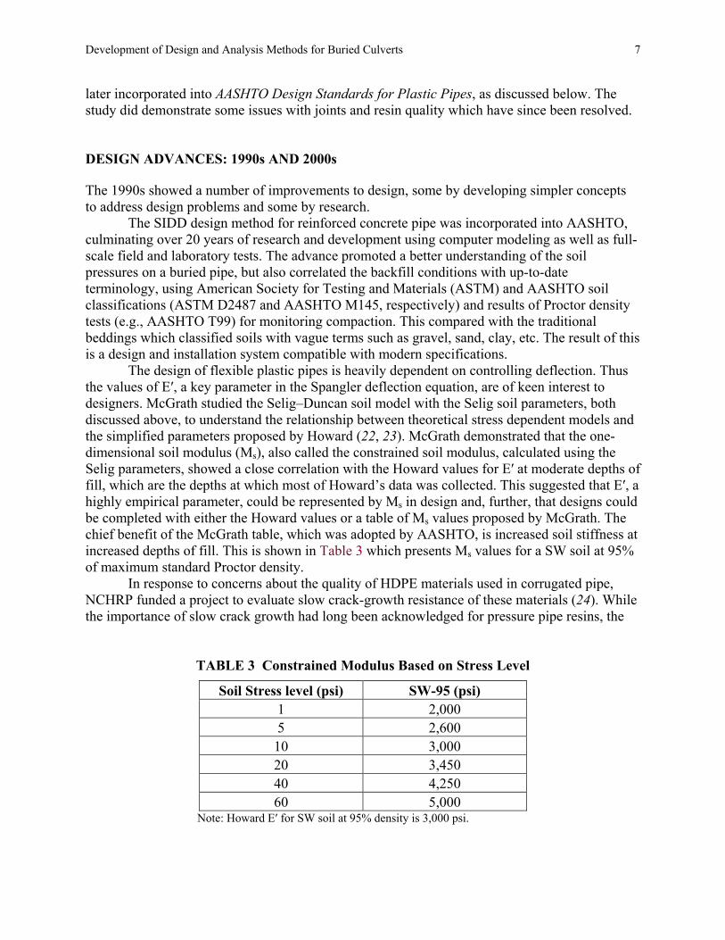
Over the years various special features, shown in Figure 8, have been utilized to improve the structural capacity of long-span corrugated metal structures. Through the use of FEM, it has been determined that thrust beams, once a standard feature on large long‐span culverts, are not effective in reducing in‐plane distress. However, they are useful to promote soil compaction and reduce longitudinal distortions. The soil bin, intuitively thought to act like a keystone soil‐block and reduce thrust stresses, has been found not to be effective in reducing thrust. Circumferential ribs are found to be effective in reducing thrust and bending in the structural plates even without the assumption of composite action.
Additionally, soft wood blocks placed under the arch ends of long-span corrugated steel structures were intended to compress and thereby induce positive soil arching. FEM and instrumented field test results showed that although some positive arching is induced, the wood does not compress enough to be effective. Finally, slotted joints, wherein bolt holes are elongated to allow 1‐in. relative slip between bolted structural plates, have been shown to be extremely effective in reducing thrust stress by up to 50%.
Finite element analysis has played an important role in the development of new culvert products. One example of a product currently in the marketplace is a pipe comprised of a steel ribs encased in HDPE. FEM analysis was used to optimize the cross‐section geometry of the plastic and steel. Another concept still in development is a fluid jacket surrounding concrete
FIGURE 8 Lessons learned about special features for long-span structural plate arches.

20 Transportation Research Circular E-C230: Culverts and Soil–Structure Interaction
pipes. FEM analysis was used to design a plastic jacket and determine the minimum water‐filled annulus. The model showed that the fluid jacket maintains the concrete pipe cross‐section in pure compression without any tension.
Although the culvert community has made heavy use of existing FEM technology, it is gratifying to know that the culvert community has contributed significantly to FEM developments in soil–structure analysis. Developments in FEM which originated in the culvert community which have expanded into nearly all fields of civil engineering include:
• Incremental construction, • Interface elements, • Hyperbolic soil models, • Automated design algorithms, • Soil–structure buckling theories, • Nonlinear material models for reinforced concrete, • Visco-elastic material models for thermoplastics, and • Plasticity models for corrugated metal.
FUTURE DESIGN CONCEPTS AND MODELS FEM likely will continue to be the analytical tool of choice for the foreseeable future. Nonetheless, simplified design formulae such as found in AASHTO LRFD Bridge Design Specifications (5) will continue to be needed and used in routine applications.
As is well known, soil stiffness has a significant impact on the structural integrity of the culvert. However, the current array of soil models based on elasticity, hypo‐elasticity, and plasticity provide a wide range of soil‐stiffness predictions, sometimes resulting in two analysts predicting different outcomes for the same culvert. It is time that the culvert community established unified model parameters and provided guidance on soil model selection and associated parameters for in-situ and imported backfill materials. REFERENCES 1. Burns, J. Q., and R. M. Richard. Attenuation of Stresses for Buried Cylinders. Proc., Symposium on
Soil Structure Interaction, Tucson, AZ, 1964. 2. Brown, C. B. The Forces on Rigid Culverts under High Fills. U.S. Bureau of Public Roads,
Washington, D.C., 1967. 3. Allgood, J. R., and S. K. Takahashi. Balanced Design and Finite-Element Analysis of Culverts.
Highway Research Record, No. 413, 1972, pp. 45–56. 4. Katona, M. G. 1.0.0.7. CANDE-2015: Culvert ANalysis and DEsign. NCHRP Project 15-28, 2015. 5. AASHTO. AASHTO LRFD Bridge Design Specifications, Customary U.S. Units, 7th Ed. American
Association of State Highway and Transportation Officials, Washington, D.C., 2016.

21
Fifty Years of Culverts and Soil–Structure Interaction European Experience
LESZEK JANUSZ VIACON Poland
JAN VASLESTAD
Norwegian Public Roads Administration
ANTONIO MIGLIO Hydraulic and Pipeline Consultant Engineer
he variety of cultures, languages and historical impacts has shaped the position of today’s Europe in engineering. As a continent comprised of 46 independent countries Europe
(Figure 1) has its challenges in the area of unification and standards (codes). Not all European countries are part of the European Union (EU) and those who are in the EU have not fully incorporated all Eurocodes.
FIGURE 1 Europe: 46 countries, 740 million people, 24 languages.
T
22 Transportation Research Circular E-C230: Culverts and Soil–Structure Interaction
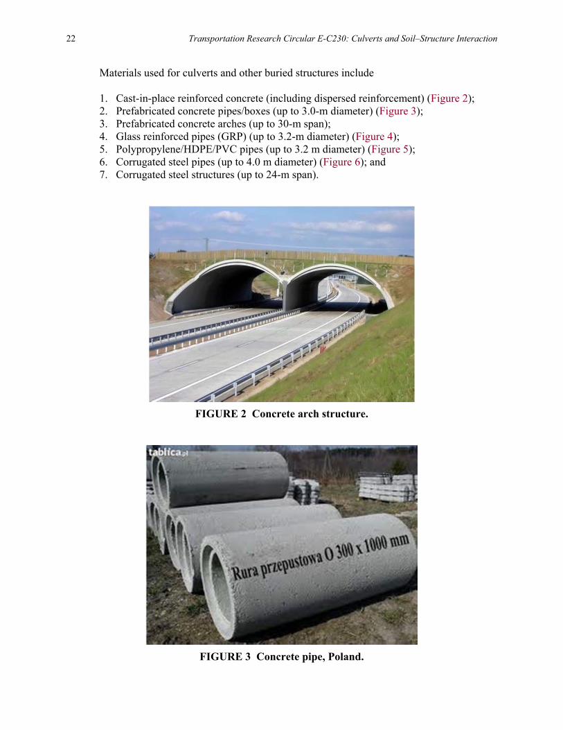
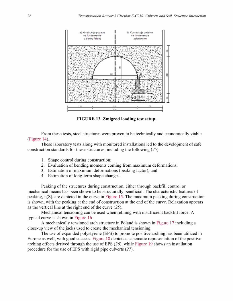
Materials used for culverts and other buried structures include 1. Cast-in-place reinforced concrete (including dispersed reinforcement) (Figure 2); 2. Prefabricated concrete pipes/boxes (up to 3.0-m diameter) (Figure 3); 3. Prefabricated concrete arches (up to 30-m span); 4. Glass reinforced pipes (GRP) (up to 3.2-m diameter) (Figure 4); 5. Polypropylene/HDPE/PVC pipes (up to 3.2 m diameter) (Figure 5); 6. Corrugated steel pipes (up to 4.0 m diameter) (Figure 6); and 7. Corrugated steel structures (up to 24-m span).
FIGURE 2 Concrete arch structure.
FIGURE 3 Concrete pipe, Poland.

Fifty Years of Culverts and Soil–Structure Interaction: European Experience 23
FIGURE 4 GRP structure.
FIGURE 5 Corrugated PE culvert pipe.

24 Transportation Research Circular E-C230: Culverts and Soil–Structure Interaction
FIGURE 6 Corrugated steel pipe.
Corrugated metal pipes were being produced in 1900 by metal works in Pruszkow near Warsaw (at that time Warsaw was a part of Russia). Plastic pipes were introduced in Europe as culverts in the beginning of the 1980s. Considering parts of Russia as part of Europe it is worthwhile to mention that Russians were producing and using corrugated steel pipes beginning in 1875 (1).
There are several producers of metal corrugated pipes and structures in Europe today. There is a full range of corrugations with 200 x 55 mm and 380 x 140 mm. The 400- x 150-mm corrugation is used but not produced in Europe. There are no European producers of aluminum corrugated structures. The increased range of spans of metal corrugated pipes and structures led to applications other than just culverts or small bridges including pedestrian underpass and animal crossings (Figures 7 through 10).
FIGURE 7 Culvert and bridge applications.

Fifty Years of Culverts and Soil–Structure Interaction: European Experience 25
FIGURE 8 Railroad underpass structures.
FIGURE 9 Pantelleria airport passage underneath a runway, Italy.
FIGURE 10 Animal highway crossing in Poland.

26 Transportation Research Circular E-C230: Culverts and Soil–Structure Interaction
After the World War II corrugated steel structures (corrugated culverts) were introduced by a joint venture of Armco and Thyssen. Until 1970, the design of corrugated culverts was based on American codes. The German railway initiated tests of corrugated steel structures, based upon which Germany introduced their own design code (2). Figure 11 is a photograph of one of these tests (3).
European standards vary from country to country. The British Standard is “Design of Corrugated Steel Buried Structures with Spans Greater Than 0.9 Meters and up to 8.0 Meters” (4). The latest development of a design method is the Swedish design method for soil–steel composite bridges developed by H. Sundquist and L. Pettersson from the Royal Institute of Technology (KTH) in Stockholm. This method has been introduced as a part of the Swedish bridge code which requires that the handbook be used in the design of soil–steel composite bridges (5). The design method was developed based on the following:
• Duncan: Soil culvert interaction method (6); • Vaslestad: arching effects (7); • Klöppel and Glock; buckling calculations (3); and • Andréasson: soil modulus for frictional materials (8). Important features of the Swedish design method are (9): • Different pipe and arch profiles can be used.
FIGURE 11 Germany 1970 pipe-arch test
(6.27 x 4.03m; 4.75-mm thick plates; load = 1,079 tons).

Fifty Years of Culverts and Soil–Structure Interaction: European Experience 27
• Any live load can be used (one, two or more lanes, concentrated and/or distributed). • The designer can calculate sectional forces (thrust and bending moments) in the
structure for any cover height (high or low). • Soil material properties can be changed, for example degree of compaction,
gradation, etc. • The structure is designed in the ultimate limit state (including fatigue) as well as the
serviceability limit state. • The method is code independent. Full-scale tests were performed in Sweden from 1983–2006, including: • 1983, Nykoping, pipe-arch with 6.1-m span (10); • 1987, Enkoping, pipe-arch with 6.0-m span (10); • 2002, Giman, box culvert with 12.0-m span (11); • 2003, Skivarpsan arch with 11.1-m span (11, 12); • 2005, Jarpas, box culvert with 8.0-m span (13); and • 2006, Jarpas, box culvert with 14.2-m span (14). From 1997 until 1999 Polish Roads and Bridges Research Institute carried a few tests on
corrugated steel structures (15, 16). Jan Vaslestad published a design method for determining the arching factor in 1990 (17).
European corrosion protection standards for corrugated steel pipe depend on whether the product is a fabricated pipe or assembled plate structure. For pipe, the governing standard is EN 10346 (18) which requires corrosion protection of 600 g/m2 of zinc, or the more stringent requirement of 1,000 g/m2 zinc coupled with 300-µm polymer layer (Figure 12). Steel structures are governed by EN 1461 (19) (from 50 to 85 µm ) + 200 to 400 µm of epoxy. The performance of buried steel structures was described by various tests (20–22). This helped to develop effective corrosion protection systems.
Figure 13 shows static and dynamic load testing conducted in Zmigrod, Poland, comparing concrete and corrugated steel foundations for steel arches. Strains, deformations, and earth pressures were measured (23, 24).
FIGURE 12 Example of corrosion protection of steel strip
used for helically corrugated steel pipes.
28 Transportation Research Circular E-C230: Culverts and Soil–Structure Interaction
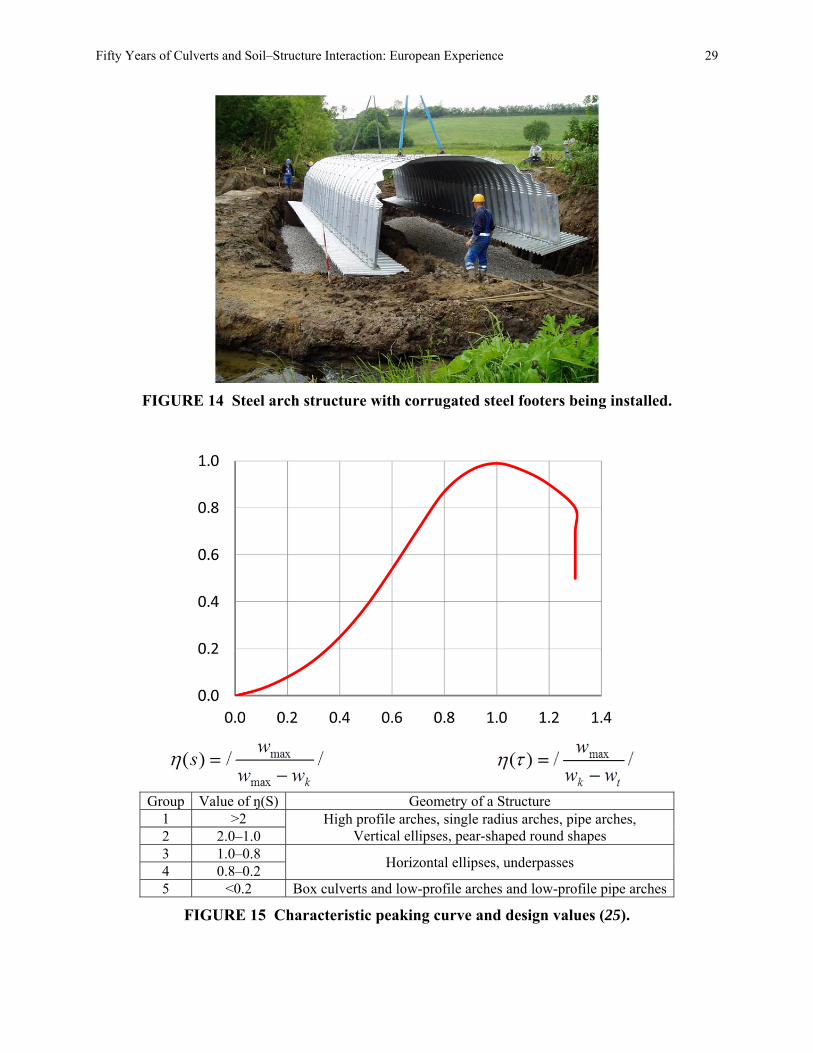
FIGURE 13 Zmigrod loading test setup.
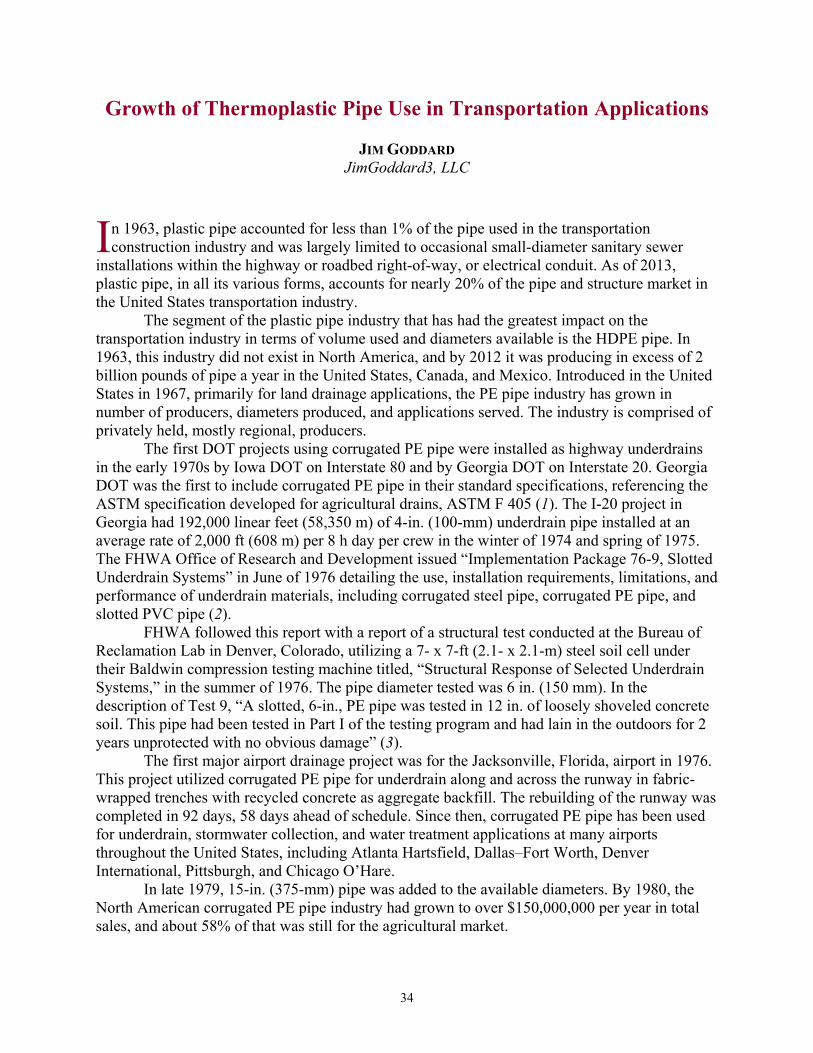
From these tests, steel structures were proven to be technically and economically viable (Figure 14).
These laboratory tests along with monitored installations led to the development of safe construction standards for these structures, including the following (25):
1. Shape control during construction; 2. Evaluation of bending moments coming from maximum deformations; 3. Estimation of maximum deformations (peaking factor); and 4. Estimation of long-term shape changes.
Peaking of the structures during construction, either through backfill control or
mechanical means has been shown to be structurally beneficial. The characteristic features of peaking, η(S), are depicted in the curve in Figure 15. The maximum peaking during construction is shown, with the peaking at the end of construction at the end of the curve. Relaxation appears as the vertical line at the right end of the curve (25).
Mechanical tensioning can be used when relining with insufficient backfill force. A typical curve is shown in Figure 16.
A mechanically tensioned arch structure in Poland is shown in Figure 17 including a close-up view of the jacks used to create the mechanical tensioning.
The use of expanded polystyrene (EPS) to promote positive arching has been utilized in Europe as well, with good success. Figure 18 depicts a schematic representation of the positive arching effects derived through the use of EPS (26), while Figure 19 shows an installation procedure for the use of EPS with rigid pipe culverts (27).
Fifty Years of Culverts and Soil–Structure Interaction: European Experience 29
FIGURE 14 Steel arch structure with corrugated steel footers being installed.
Group Value of ŋ(S) Geometry of a Structure
1 >2 High profile arches, single radius arches, pipe arches, Vertical ellipses, pear-shaped round shapes 2 2.0–1.0
3 1.0–0.8 Horizontal ellipses, underpasses
4 0.8–0.2 5 <0.2 Box culverts and low-profile arches and low-profile pipe arches
FIGURE 15 Characteristic peaking curve and design values (25).

30 Transportation Research Circular E-C230: Culverts and Soil–Structure Interaction
FIGURE 16 Mechanical tensioning of an arch structure.
FIGURE 17 Mechanically tensioned arch construction in Poland showing the jacks used.
FIGURE 18 The effect of the use of EPS to promote positive soil arching (26).

Fifty Years of Culverts and Soil–Structure Interaction: European Experience 31
FIGURE 19 Common procedure for installation of rigid culverts
using an imperfect ditch backfilled with EPS (27).
The use of EPS for load reduction is • Easy to specify material characteristics using EPS; • There is no long-term decomposition of EPS as there is with organic materials; • EPS is easy to install, with controlled geometry; • Vertical earth pressure can be reduced up to 25% of overburden in granular material,
and as much as 50% in cohesive material; and • Long-term earth pressure measurements show the arching effect is stable over time
using EPS. Ongoing research and development in Europe includes: • Methodology to determine the load-bearing capacity of existing bridges and
structures; • Design methodology to determine fatigue tolerance and cyclic loading capacity; • Design methodology for high-speed train loading; and • Life-cycle cost analysis, including considering the environmental footprint and the
use of recycled materials. Future European research includes: • Advanced corrosion protection systems; • Higher grade steel; • Deeper, larger corrugations; • Alternative metals and other materials;

32 Transportation Research Circular E-C230: Culverts and Soil–Structure Interaction
• Improved connection systems; • Backfill improvements; and • On-line monitoring systems for structures.
REFERENCES 1. Makowski, J. And B. Kulczycki, Podsumowanie metod realizacji przepustu doświadczalnego z
blachy falistej w Bolimowie, Materiały na kursokonferencję: Galwanizowane przepusty z blachy falistej jako nowy element organizacji i ekonomiki projektowania dzieł sztuki inżynierskiej na trasach komunikacyjnych, str. 86-101, Instytut Dróg i Mostów Politechniki Warszawskiej, Warszawskie Przedsiębiorstwo Robót Drogowych, Stowarzyszenie Inżynierów i Techników Komunikacji, Towarzystwo Naukowe Organizacji i Kierownictwa Oddział Warszawski, Warszawa 1980.
2. Allgemeines Rundschreiben Strassenbau Nr 20/1997. Wellstahlrohre;-Bedingungen für die Anwendung von Wellstahlrohren, Ausgabe1997“, Reg. Nr.05.40, ARS 20/97, Bonn 23 Mai 1997.
3. Klöppel, K., and D. Glock, Theoretische und experimentelle Untersuchungen zu den Traglastproblemen beigewiecher, in die Erde eingebetteter Rohre, Veröffentlichung des Instituts Statik und Stahlbau der Technischen Hochschule Darmstadt, 3/1979, H-10.
4. Design Manual for Roads and Bridges, Design of Corrugated Steel Buried Structures With Spans Not Exceeding 8 m (Including Circular Arches), Vol. 2, Section 2, Part 6 BD 12/95, Highway Agency, The Scottish Office Development Department, The Welsh Office, The Department of the Environment for Northern Ireland, December 1995.
5. Pettersson, L., and H. Sundquist, Design of Soil–Steel Composite Bridges. TRITABKN, Report 112, 5th Edition, KTH Royal Institute of Technology, Stockholm, Sweden.
6. Flener, E. B. Full-Scale Testing of Two Corrugated Steel Box Culverts with Different Crown Stiffness, TRITA-BKN. Rapport 93, ISSN 1103-4289, ISRN KTH/BKN/R-93-SE, Byggkonstruktion 2006, KTH SE-10044, Stockholm, Sweden.
7. Vaslestad, J. Long-Term Behavior of Flexible Large-Span Culverts. Norwegian Public Road Administration Publication No 74, September 1994.
8. Andréasson, L. Compressibility of Cohesionless Soils: A Laboratory Investigation. National Swedish Building Research, Stockholm, Sweden, 1973 (in Swedish).
9. Pettersson, L. Full-Scale Tests and Structural Evaluation of Soil–Steel Flexible Culverts with Low Height of Cover. Doctoral thesis. TRITA_BKN Bulletin 93, KTH Royal Institute of Technology, Stockholm, Sweden, 2007.
10. Pettersson, L. Full-Scale Live Loads Tests on a Corrugated Steel Culvert. IABSE Colloquium Tunnel Structures, 1998.
11. Pettersson, L., and H. Sundquist. Design of Long Span Flexible Metal Culverts. TRITA-BKN, Report 58, Brobyggnad 2000, English edition, 2003, ISSN 1103-4289, KTH, Stockholm, Sweden.
12. Pettersson, L. Full-Scale Live Loads Tests on a Corrugated Steel Culvert, IABSE Colloquium Tunnel Structures, 1998.
13. Flener, E. B. Field Testing of a Long-Span Arch Steel Culvert Railway Bridge Over Skivarpsan, Sweden, PART I, TRITA-BKN, Rapport 72, ISSN 1103-4289, ISRN/KTH/BKN/R-84-SE, Byggkonstruktion, 2004.
14. Flener, E. B. Field Testing of a Long-Span Arch Steel Culvert Railway Bridge over Skivarpsan, Sweden, PART II, TRITA-BKN Rapport 84, ISSN 1103-4289, ISRN/KTH/BKN/R-84-SE, Byggkonstruktion, 2004.
15. Vaslestad, J., and A. Wysokowski. Full-Scale Testing of Multiplate Corrugated Steel Structures in Poland. Proc., 6th Conference on Shell Structures and Applications, Gdansk, Poland, October 1998.
16. Wysokowski, A., and J. Vaslestad. Ful-Scale Fatigue Testing of large-Diameter Multi–Plate Corrugated Steel Culverts, Archives of Civil Engineering, Vol. XLVIII, No. 1, 2002.

Fifty Years of Culverts and Soil–Structure Interaction: European Experience 33
17. Vaslestad, J. Soil Structure Interaction of Buried Culverts. Doktor Ingeniøravhandling, Vol. 1990:7, Institutt for Geoteknikk Trondheim, ISBN 82-7119-161-6, Norges Tekniske Høgskole.
18. PN-EN 10346:2011 Continuously Hot-Dip Coated Steel Flat Products for Cold Forming—Technical Delivery Conditions.
19. BS EN ISO 1461. Hot Dip Galvanized Coatings on Fabricated Iron and Steel Articles, Specifications and Test Methods, 2009.
20. Mattsson, H.-Å., and H. Sundquist. The Real Service Life and Repair Methods of Steel Pipe Culverts in Sweden, Archives of Institute of Civil Engineering, First European Conference on Buried Flexible Steel Structures, Poznan, Poland, 2007.
21. Pettersson, L., and A. Wadi. Full-Scale Live Load Tests on older Soil–Steel Composite Bridges Close to Skellefteå, Sweden (test report). KTH Structural Engineering and Bridges, 2013.
22. Camitz, G., U. Bergdahl, and T. G. Vinka. Stålpålars beständighet mot korrosion i jord, En sammanställning av kunskaper och erfarenheter (The corrosion resistance of steel piles in soil - A compilation of knowledge and experience), Commission on Pile Research, Report 105, Linköping, Sweden, 2009.
23. Machelski, C., J. B. Michalski, and L. Janusz. Application of Flexible Foundations Under Soil–Steel Bridges. 89th Annual Meeting Transportation Research Board, Washington, January 11-15, 2010 pp. 10-0950.
24. Machelski C. and M., Mońka, Prognosis and measurements of deformation of soil–steel structure settled on steel corrugated plate foundations. Archives of Institute of Civil Engineering, 2th European Symposium, Rydzyna, 2012, p. 147–156.
25. Machelski C., J.B. Michalski, and L. Janusz. Deformation Factors of Buried Corrugated Structures. Transportation Research Record: Journal of the Transportation Research Board, No. 2116, 2009, pp. 70–75.
26. Miglio, A. The Use of EPS Geofoam for Load Reduction on Buried Rigid Pipes Under High Fills. Presented at 90th Annual Meeting of the Transportation Research Board, Washington, D.C., 2011.
27. Statens Vegvesen. Geoteknikk i vegbygging. Håndbok V220, utgave av 2014 (in Norwegian).
34
Growth of Thermoplastic Pipe Use in Transportation Applications
JIM GODDARD JimGoddard3, LLC
n 1963, plastic pipe accounted for less than 1% of the pipe used in the transportation construction industry and was largely limited to occasional small-diameter sanitary sewer
installations within the highway or roadbed right-of-way, or electrical conduit. As of 2013, plastic pipe, in all its various forms, accounts for nearly 20% of the pipe and structure market in the United States transportation industry.
The segment of the plastic pipe industry that has had the greatest impact on the transportation industry in terms of volume used and diameters available is the HDPE pipe. In 1963, this industry did not exist in North America, and by 2012 it was producing in excess of 2 billion pounds of pipe a year in the United States, Canada, and Mexico. Introduced in the United States in 1967, primarily for land drainage applications, the PE pipe industry has grown in number of producers, diameters produced, and applications served. The industry is comprised of privately held, mostly regional, producers.
The first DOT projects using corrugated PE pipe were installed as highway underdrains in the early 1970s by Iowa DOT on Interstate 80 and by Georgia DOT on Interstate 20. Georgia DOT was the first to include corrugated PE pipe in their standard specifications, referencing the ASTM specification developed for agricultural drains, ASTM F 405 (1). The I-20 project in Georgia had 192,000 linear feet (58,350 m) of 4-in. (100-mm) underdrain pipe installed at an average rate of 2,000 ft (608 m) per 8 h day per crew in the winter of 1974 and spring of 1975. The FHWA Office of Research and Development issued “Implementation Package 76-9, Slotted Underdrain Systems” in June of 1976 detailing the use, installation requirements, limitations, and performance of underdrain materials, including corrugated steel pipe, corrugated PE pipe, and slotted PVC pipe (2).
FHWA followed this report with a report of a structural test conducted at the Bureau of Reclamation Lab in Denver, Colorado, utilizing a 7- x 7-ft (2.1- x 2.1-m) steel soil cell under their Baldwin compression testing machine titled, “Structural Response of Selected Underdrain Systems,” in the summer of 1976. The pipe diameter tested was 6 in. (150 mm). In the description of Test 9, “A slotted, 6-in., PE pipe was tested in 12 in. of loosely shoveled concrete soil. This pipe had been tested in Part I of the testing program and had lain in the outdoors for 2 years unprotected with no obvious damage” (3).
The first major airport drainage project was for the Jacksonville, Florida, airport in 1976. This project utilized corrugated PE pipe for underdrain along and across the runway in fabric-wrapped trenches with recycled concrete as aggregate backfill. The rebuilding of the runway was completed in 92 days, 58 days ahead of schedule. Since then, corrugated PE pipe has been used for underdrain, stormwater collection, and water treatment applications at many airports throughout the United States, including Atlanta Hartsfield, Dallas–Fort Worth, Denver International, Pittsburgh, and Chicago O’Hare.
In late 1979, 15-in. (375-mm) pipe was added to the available diameters. By 1980, the North American corrugated PE pipe industry had grown to over $150,000,000 per year in total sales, and about 58% of that was still for the agricultural market.
I

Growth of Thermoplastic Pipe Use in Transportation Applications 35
Growth in volume and applications accelerated after 1981, with the introduction of 18-in. (450-mm) and 24-in. (600-mm) pipe. In September 1981, Ohio DOT installed the first known corrugated PE cross-drain culvert under a state highway. The site is located in southeastern Ohio (Figure 1) and this pipe replaced a failing culvert that had collapsed due to attack from the abrasive and low pH (pH <4) flow through it. At this site the Ohio DOT had been replacing other types of pipe every 2 to 5 years. This PE cross-drain is still in service after 32 years and appears unchanged. Within a relatively few years state DOT maintenance departments were using corrugated PE pipe extensively to replace pipe of other materials in areas where corrosion was a problem.
One of the seminal technical developments in the industry, at least as it applied to the United States markets, was a decision made in March 1983 to promote and produce a variable pipe stiffness, with nominal pipe stiffness decreasing with increasing diameters. These stiffness values are included in AASHTO M294, “Corrugated Polyethylene Pipe, 300- to 1500-mm diameter.” AASHTO M304, “Standard Specification for Polyvinyl Chloride (PVC) Profile Wall Drain Pipe and Fittings Based on Controlled Inside” diameter uses a similar approach, though the stiffness of the pipes are somewhat different (4). This was a substantial deviation from the direction PVC sanitary sewer pipe was taking, with a constant pipe stiffness of 46 lb per inch of sample length per inch of deflection per ASTM D2412 (5). But it was not all that radical, with corrugated steel pipe having nominally lower pipe stiffness as diameters increased and with corrugated aluminum pipe having much lower values throughout the diameter range. It was also analogous to the stiffness values in ASTM F894, which hid the decreasing stiffness values by establishing a ring stiffness constant based on testing at four times the loading rate of ASTM D2412 [2 in. per minute rather than 0.5 in. per minute (50.8 mm per minute rather than 12.7mm per minute)] and determining the stiffness at 3% deflection instead of 5% in ASTM D2412 (5, 6). The actual stiffness values selected are shown in Table 1, along with comparable CMP-tested stiffness.
FIGURE 1 Ohio DOT installation of 24-in. (600-mm) diameter culvert after 27 years in mine acid run-off.

36 Transportation Research Circular E-C230: Culverts and Soil–Structure Interaction
TABLE 1 Comparative Pipe Stiffness (in pounds per inch of sample length per inch of deflection at 5% deflection)
Diameter, in. (mm)
Corrugated Steel Pipe
Corrugated Aluminum
Pipe Corrugated HDPE Pipe
AASHTO M294-13 (4)
AASHTO M304 (7)
12 (300) 145 48.3 45 50 46 15 (375) 104 34.7 42 42 38 18 (450) 79 26.4 40 40 32 24 (600) 51 17.1 34 34 24 30 (750) 41 13.8 28 28 19 36 (900) 31.5 10.5 22 22 16 42 (1,050) 30 10.0 20 20 14 48 (1,200) 24 8.0 17.5 18 12 60 (1,500) 20.1 6.7 14 14 — 72 (1,800) 15.3 5.1 11 — — 84 (2,100) 13.7 4.6 10 — —
NOTE: The reported values for AASHTO M304 are greater than those typically found in standard production pipe. All tested samples were 24 in. in length in accordance with ASTM D2412 (5).
The CMP values are based on standard sinusoidal 2-2/3” x ½” corrugations in the standard gages for those diameters. These corrugated HDPE pipe stiffness values were generated when the largest diameter manufactured in the United States was 24 in. (600 mm) diameter. They represent a decreasing flexibility factor as diameters increase, while the CMP industry promoted a constant maximum flexibility factor for their pipe; 9.5 x 10⁻² for corrugated aluminum pipe (as flexibility factor goes down, stiffness goes up). The flexibility factor of the corrugated HDPE 12 in. (300 mm) pipe is 9.5 x 10⁻², but the flexibility factor for the 60 in. (1500 mm) pipe is 6.3 x 10⁻². This information was published in Transportation Research Record 903 (8).
This variable pipe stiffness approach permitted the design and marketing of very large–diameter pipe at competitive costs to competitive materials, something that a constant pipe stiffness of 46 psi (320 kPa) would not have permitted. These minimum pipe stiffness values are required, unchanged from the 1982 recommendations except for the increase of 12-in. (600-mm) pipe stiffness from 45 psi (310 kPa) to 50 psi (345 kPa), by the current AASHTO M294 specification and in ASTM F2306 and F2648 (4, 9, 10).
PE resins available to the industry have changed significantly as the industry grew. In the early years the primary resins used were “bottle grade” materials, which could be variable in processing performance from lot to lot. Today, the major resin companies all manufacture resins specifically tailored for this industry and these pipe applications. These materials have very consistent material properties and high stress-crack resistance. The resins required in the current AASHTO M294 specification were not even available in 2000 (4).
The next big increase in applications and use came with the development of the manufacturing technology to make corrugated PE pipe with a smooth interior wall in 1987. Developed primarily to improve the flow capacity of the pipe by substantially lowering the Manning’s “n” value (roughness coefficient), the new pipe also had substantially increased longitudinal stiffness, making it easier to install. The industry now had a product that could compete with other smooth interior pipe types. The addition of a smooth interior had a

Growth of Thermoplastic Pipe Use in Transportation Applications 37
significant role in increasing the use of this pipe in storm sewer, closed systems, or long, relatively flat, culverts because of its lower Manning’s “n” value.
At the same time, larger diameter pipes were being developed, with 30 in. (750 mm) and 36 in. (900 mm) introduced in 1987, 42 in. (1050 mm) and 48 in. (1200 mm) manufactured in 1991, and with 60 in. (1500 mm) produced in 1998. In those diameters, only smooth interior pipe has been manufactured and marketed.
With each increase in diameter, Moser, Watkins, and Folkman of Utah State University conducted the soil cell tests (Figure 2) on those new diameters (8). These tests were open to DOT engineers and others, and at various times at least five DOTs were represented at the test site in Logan, Utah. Each diameter or significant wall design change was tested using a coarse-grained material (SW or Sn designation) as backfill compacted to three different densities, 95% Standard Proctor Density (SPD), 85% SPD, and 75% SPD. The most important information gained from these tests was the relative performance of this pipe to other pipe types previously tested the same way in the same test facility. These comparisons demonstrate that a properly designed pipe wall profile can out-perform a much stiffer pipe with a less stable wall design. Most of this testing is reported in “Buried Pipe Design” by Moser and Folkman (11). Some DOTs viewed these tests as proof of performance that were required prior to any acceptance and use of the pipe.
Also, with each increase in diameter, test installations were placed under pavement by various DOTs, normally by their maintenance forces. For instance, the first 24-in. diameter HDPE cross-drain was installed by the Ohio DOT. The first two 48-in. (1,200-mm) HDPE installations were installed by the Ohio DOT and by Pennsylvania DOT. The first 60-in. HDPE installation by a DOT was installed by the Missouri DOT. All of these pipes are still in place and performing well.
FIGURE 2 Utah State University soil cell full test, loading beams down, and load being applied to soil surface over 48-in. (1,200-mm) pipe.

38 Transportation Research Circular E-C230: Culverts and Soil–Structure Interaction
In 1987, with the cooperation of Pennsylvania DOT and Mashuda Construction, and technical assistance from E. Selig of the University of Massachusetts, advanced drainage systems had a 24-in. (600-mm) pipe installed under I-279 north of Pittsburgh, Pennsylvania, (Figure 3) with a maximum fill height of 100 ft (30.5 m) (12). This pipe has been the subject of thousands of pages of reports, including a full inspection and corresponding report after 20 years (13) and an unpublished inspection after 25 years. The total pipe length is 576 ft, with 220 ft being smooth interior and the remainder being corrugated inside and out. A great deal has been learned, or confirmed, from this study, including:
1. Under very high fills and corresponding loads, the HDPE compresses slightly under
wall thrust. In this case, the maximum hoop compression was 1.9%. 2. The hoop compression and subsequent hoop shortening, combined with the vertical
deflection creates a substantial soil arch over the pipe. In this case the vertical soil pressure at the crown of the pipe is about 23% of the vertical soil column weight.
3. Deflection and shortening stabilized in a relatively short period of time; less than 1 year after completion of the fill.
4. Antioxidant levels within the HDPE material have remained much higher than anticipated after 20 years of service, with very little reduction in oxidation induction time or oxidation induction temperature values. These values represent the thermal stability of the material as tested in accordance with ASTM standards.
5. Material properties, specifically tensile strength at yield and flexural modulus have not changed over 20 years. The Pennsylvania Deep Burial Study confirmed that this type of pipe could withstand substantial loads for long periods of time without failure. It has become a very convincing proof for many specifying engineers.
FIGURE 3 Pennsylvania Deep Burial Study pipe under I-279.

Growth of Thermoplastic Pipe Use in Transportation Applications 39
In 1999, Ohio University installed six runs 900-ft (274-m) long of thermoplastic pipe in an embankment condition with 20 ft (6 m) and 40 ft (12 m) of fill in a research project funded by the Ohio DOT, the Pennsylvania DOT, and FHWA (14, 15). Pipe diameters and quantities included 3,600 ft (1,095 m) of 30-in. (750-mm) diameter pipe; 900 ft (274 m) of 42-in. (1,050-mm) diameter pipe; and 900 ft (274 m) of 60-in. (1,500-mm) diameter pipe. Backfill materials included gravel or sand and compaction levels were 86% SPD, 90% SPD, or 96% SPD. Bedding thickness was also varied on two of the runs. Two of the 30-in. (750-mm) runs were profile wall PVC pipe and the remaining runs were corrugated HDPE pipe. A representation view of the site layout is given in Figure 4 and the actual site after construction is shown in Figure 5. There have been no signs of structural distress in any of the pipe in this study. Sensor readings that represent pipe performance and soil–structure interaction stabilized within 3 months or less after construction was completed. Circumferential shortening in the HDPE pipe was –0.1 % to less than 1%. The VAF for the pipe buried 40 ft (12 m) deep ranged from 0.65 to 0.28.
FIGURE 4 Ohio University Deep Burial Study pipe layout.
FIGURE 5 Ohio University Deep Burial Study after installation.

40 Transportation Research Circular E-C230: Culverts and Soil–Structure Interaction
After the addition of the smooth interior and the development of larger diameters, the changes in pipe joint performance have significantly changed the industry and the types of service. Gasketed bell and spigot joints are watertight, as defined by ASTM D3212 (16) and in AASHTO PP63-09, “Pipe Joint Selection for Highway Culvert and Storm Drains” (17).
Over the last 50 years NCHRP research has had considerable impact on the growth of the plastic pipe industry, the quality of its products, and the acceptance of those products. Most of these projects were initiated through Research Problem Statements developed by the TRB Standing Committees on Culverts and Hydraulic Structures and Subsurface Soil–Structure Interaction. The Research Problem Statements include:
• NCHRP Report 116: Structural Analysis and Design of Pipe Culverts. While not
specifically covering plastic pipe, this project did provide structural design guidance for the use of these products (18).
• NCHRP Report 225: Plastic Pipe for Subsurface Drainage of Transportation Facilities. This project did specifically make recommendations regarding the installation and material specifications for perforated underdrain pipe, both PVC and HDPE. The largest diameter pipe included was 8 in. (200 mm) (19).
• NCHRP Report 429: HDPE Pipe: Recommended Material Specifications and Design Requirements. This project looked at pipe failures and material cracking and recommended materials specifications to minimize cracking potential. The majority of the pipe was manufactured by a spiral process, which is no longer used in the diameters tested. These recommendations were accepted by the AASHTO Subcommittee on Materials and are now part of AASHTO M294 (4, 20).
• NCHRP Report 438: Recommended LRFD Specifications for Plastic Pipe and Culverts. This project developed the methodology to incorporate thermoplastic pipe into the AASHTO LRFD Bridge Design Specifications (Section 12) (21, 22).
• NCHRP Report 619: Modernize and Upgrade CANDE for Analysis and LRFD Design of Buried Structures. This project upgraded and simplified the CANDE program and incorporated the LRFD Section 12 changes effecting plastic pipe (23).
• NCHRP Report 631: Updated Test and Design Methods for Thermoplastic Drainage Pipe. This project made extensive recommendations to upgrade testing of plastic pipe and to modify existing design methods to reflect those changes. Much of this has been adopted by AASHTO (24).
• NCHRP Report 647: Recommended Design Specifications for Live Load Distribution to Buried Structures. This project improved the prediction of live load distribution over all types of buried structures, impacting design procedures for all pipe types (25).
• NCHRP Report 696: Performance of Corrugated Pipe Manufactured with Recycled Polyethylene Content. With considerable interest in utilizing recycled plastic in products of all types, including pipe, this project used lab tests on a broad range of recycled PE blends and made recommendations for test requirements and contaminant limits (26). Since this project did not include any pipe tests in the ground, a follow-up project was initiated to calibrate these results and recommendations. That project is now underway as NCHRP Project 04-39, “Field Performance of Corrugated Pipe Manufactured with Recycled Polyethylene Content.”
• NCHRP Project 15-38, “Design Requirement for Culvert Joints.” This project looked at culvert pipe joints, including PVC and HDPE pipe. The results should be valuable to end users in selecting pipe types for different installation conditions (27).

Growth of Thermoplastic Pipe Use in Transportation Applications 41
There have also been a number of NCHRP Syntheses of Highway Practice that impacted the plastic pipe industry. These are listed below:
• NCHRP Syntheses of Highway Practice 50: Durability of Drainage Pipe (28), • NCHRP Syntheses of Highway Practice 96: Pavement Subsurface Drainage Systems
(29), • NCHRP Syntheses of Highway Practice 239: Pavement Subsurface Drainage Systems
(30), and • NCHRP Syntheses of Highway Practice 254: Service Life of Drainage Pipe (31).
SPECIFICATION HISTORY AND DEVELOPMENT The growth of any widely used pipe product is directly impacted by the development of standard specifications. These standards are, in turn, impacted by the research outlined above. Without the NCHRP work outlined above and the industry research these standards would not exist and the use of these products would be limited. In the United States, the AASHTO and ASTM are the primary developers of pipe related material standards. AASHTO specifications have had significant impact on the industry’s growth. AASHTO specifications are referenced by the state highway departments, the District of Columbia Transportation Department, the Puerto Rico Highway Department, FHWA, Federal Aviation Administration (FAA), the U.S. Army Corps of Engineers (USACE), and other government agencies. These AASHTO pipe specifications (Table 2)are developed by the AASHTO Subcommittee on Materials, and only state materials engineers can vote on them for passage or changes.
AASHTO M252, “Corrugated Polyethylene Drainage Pipe,” was first passed and published by AASHTO in 1976, and was intended, primarily, for underdrain or subdrain applications. Initially the standard just included 4-in. (100-mm) and 6-in. (150-mm) pipe, but as available diameters increased they were added to M252, until, ultimately, diameters included through 15 in. (375 mm). Currently, AASHTO M252 includes 3-in. (75-mm) through 12-in. (300-mm) diameters (32).
In 1986, AASHTO M294, “Corrugated Polyethylene Pipe, 300- to 1,500-mm Diameter,” was passed and published. Initially, the M294 specification included only 12 in. (300 mm) diameter through 24-in. (600-mm) diameter, with the 12 in. (300 mm) and 15 in. (375 mm) being removed from M252. As available diameters increased and the appropriated testing on those diameters completed the new sizes were added to the standard (4).
AASHTO goes beyond materials standards and has design standards, construction standards, and a quality assurance program as outlined in Table 3.
TABLE 2 AASHTO Subcommittee on Materials Standards AASHTO Designation Title Year ApprovedM252 (32) Corrugated Polyethylene Drainage Pipe 1976 M294 (4) Corrugated Polyethylene Pipe, 300 to 1,500-mm diameter 1986

42 Transportation Research Circular E-C230: Culverts and Soil–Structure Interaction
TABLE 3 AASHTO Pipe Standards AASHTO Organization PE Pipe Standard
Subcommittee on Materials AASHTO M252 (32) AASHTO M294 (4)
Subcommittee on Bridges and Structures—Design AASHTO LRFD Bridge Design Specifications, Section 12 (22)
Subcommittee on Bridges and Structures—Construction AASHTO LRFD Bridge Construction Specifications, Section 30 (33)
NTPEPa NTPEP for thermoplastic pipe a National Transportation Product Evaluation Program.
All of these standards served to broaden acceptance and increase confidence in these
products. They also served to establish minimum performance and manufacturing standards for these products.
ASTM standards covering these products are listed in Table 4. Under AASHTO, a NTPEP was developed for PE pipe. The program, using two
independent laboratories, randomly samples pipe production from participating manufacturers and tests those samples in accordance with all of the test requirements of AASHTO M294. These test results are then made available on the AASHTO website. A manufacturing plant audit is also included. Recently, some PVC manufacturers have worked with AASHTO to develop a companion program. These programs provide additional assurance that the manufacturers are meeting the requirements of the standards. The NTPEP will likely expand to include other pipe types in the future.
Currently, all of the state DOTs specify and use corrugated PE pipe for some applications. Most specify it for culvert and storm sewer applications. FHWA, FAA, the USACE, and other agencies include it in their specifications. The Federal Emergency Management Agency, in FEMA P-675, includes guidance on the application and installation of corrugated PE pipe in dams (48). FEMA, as the lead agency for the National Dam Safety Program, sponsored development of this document in conjunction with the Association of State Dam Safety Officials, Bureau of Reclamation, Mine Safety and Health Administration, Natural Resources Conservation Service, and USACE.
Corrugated PE pipe has been used successfully to reline failing pipe by a number of agencies. In 1983–1984, Oklahoma DOT relined more than 40 corroded steel pipe cross-drains. In 2007, Delaware DOT relined a failing reinforced concrete pipe under a major thoroughfare in Wilmington, Delaware, (Figure 6) with no disruption of traffic and an estimated savings of nearly $1,000,000 versus removing and replacing the existing pipe. SUMMARY OF THE LAST 50 YEARS The corrugated PE pipe industry in North America today consists of about 20 producers, ranging from large international companies to small single-plant operations serving local markets. Its participation in the transportation infrastructure has grown from nothing in 1966 to a multibillion-dollar industry. As an industry, it dominates the underdrain–subsurface drainage market. It has a double-digit share of the culvert and storm sewer market.

Growth of Thermoplastic Pipe Use in Transportation Applications 43
TABLE 4 ASTM Pipe Standards Designation Title Year Approved
F405 (1) Standard Specification for Corrugated Polyethylene Pipe and Fittings
1974
F449 (34) Standard Practice for Installation of Corrugated Polyethylene Pipe for Agricultural Drainage or Water Table Control
1976
F481 (35) Standard Practice for Installation of Thermoplastic Pipe and Corrugated Pipe in Septic Tank Leach Fields
1976
F667 (36) Standard Specification for Large-Diameter Corrugated Polyethylene Pipe and Fittings
1980
F2306 (9) Standard Specification for 12- to 60-in. (300- to 1,500-mm) Annular Corrugated Profile Wall Polyethylene Pipe and Fittings for Gravity-Flow Storm Sewer and Subsurface Drainage Applications
2005
F2648 (10) Standard Specification for 2- to 60-in. (50- to 1,500-mm) Annular Corrugated Profile Wall Polyethylene Pipe and Fittings for Land Drainage Applications
2007
D7001 (37) Standard Specification for Geocomposites for Pavement Edge Drains and Other High-Flow Applications
2004
F2433 (38) Standard Test Method for Determining Thermoplastic Pipe Wall Stiffness
2005
D1248 (39) Standard Specification for Polyethylene Plastics Extrusion Materials for Wire and Cable
1952
D3350 (40) Standard Specification for Polyethylene Plastics Pipe and Fitting Materials
1974
F2136 (41) Test Method for Notched, Constant Ligament-Stress Test to Determine Slow Crack-Growth Resistance of HDPE Resins or HDPE Corrugated Pipe
2001
F2736 (42) Standard Specification for 6- to 30-in. (152- to 762-mm) Polypropylene Corrugated Single Wall Pipe and Double Wall Pipe
2011
F2762 (43) Standard Specification for 12- to 30-in. (300- to 750-mm) Annular Corrugated Profile Wall Polyethylene Pipe and Fittings for Sanitary Sewer Applications
2011
F2763 (44) Standard Specification for 12- to 60-in. (300- to 1,500-mm) Triple Profile Wall Polyethylene Pipe and Fittings for Sanitary Sewer Applications
2011
F2764 (45) Standard Specification for 6- to 60-in. (150- to 1,500-mm) Polypropylene Triple Wall Pipe and Fittings for Non-Pressure Sanitary Sewer Applications
2011
F2881 (46) Standard Specification for 12- to 60-in. (300 to 1,500-mm) Polypropylene Dual Wall Pipe and Fittings for Non-Pressure Storm Sewer Applications
2011
F2986 (47) Standard Specification for Corrugated Polyethylene Pipe and Fittings for Mine Leachate Applications
2012

44 Transportation Research Circular E-C230: Culverts and Soil–Structure Interaction
FIGURE 6 Delaware DOT reline project in Wilmington. WHAT DOES THE FUTURE HOLD Over the next 20 years, expect more changes in the pipe industry. Possibly the biggest change will be the quantity of pipe installed using trenchless technology. This area has been the fastest growing segment of the pipe market in recent years, and that growth is expected to continue. This includes the repair and relining of deteriorated structures, but also will see growth in boring, tunneling, and directional drilling of more, and larger structures.
Pipe diameters will continue to increase. There are technologies available today that can produce thermoplastic pipe larger than 120 in. (3,000 mm) (Figure 7). These are spiral wound technologies and they have been successful in industrial and sanitary sewer applications.
There will also be an increase in the development and use of composite material designs. There are several existing technologies combining PE and steel elements into the pipe wall (Figure 8). There will be other combinations as well, including fiber-reinforced plastic materials.
The resins themselves will continue to change and improve. The last decade has seen resin properties go far beyond anything that was available prior to that time in terms of both mechanical and chemical properties. PE, polypropylene, and PVC pipe should all see increased use.
Resins costs, particularly those derived from ethylene is expected to remain low. The discovery and exploitation of the vast quantities of natural gas beneath the United States has changed the traditional cost structure of natural gas versus oil, with natural gas becoming considerably less expensive.
TRB and its technical committees likely are to continue to lead the way in identifying needed research on buried structures and promoting the funding of these studies. The TRB Annual meeting also is likely to continue to provide a forum for the discussion and dissemination

Growth of Thermoplastic Pipe Use in Transportation Applications 45
FIGURE 7 3,000-mm PE pipe.
FIGURE 8 A steel-reinforced PE pipe utilizing an arch-shaped steel corrugation incorporated into the pipe wall.
46 Transportation Research Circular E-C230: Culverts and Soil–Structure Interaction
of information regarding industry advances to the benefit of the transportation industry and the public it serves. FUTURE OF PIPE/SOIL SYSTEMS
Predicting the future is always fraught with risks. One thing that can be safely predicted is that the next 20 years will see more changes and more developments than the last 20 years.
Material changes and developments will probably lead the way. There are expected to be better, stronger, more-durable cements and concrete mixtures used in pipe and structure manufacture. Alternate reinforcing materials may replace much of the reinforcing steel. Flexible, thinner wall concrete pipe likely will be manufactured and used.
Foreseeable changes in steel pipe include new coating systems to protect against corrosion and abrasion and new steel alloys becoming available.
It is anticipated that new thermoplastic resins will be available, offering improved performance. As an example, the HDPE resins commonly used today in the manufacture of corrugated PE pipe were not available in the year 2000. Polypropylene use is expected to grow. Other, new resins may enter the market. Plastic blends also are expected to increase, as are the use of recycled materials. Large-diameter plastic pipe likely will become common, many manufactured with new wall designs or as composites of thermoplastic and reinforcing materials.
The use of small arch structures of concrete, steel, or thermoplastic materials as culvert will increase as the demand for improved fish passage and for animal passage beneath roadways and railways.
Additional changes to materials and practices may include:
• Changes to backfill and bedding materials to include more and various recycled materials, alone or blended with native materials.
• Increased use of sensors and “smart structures” during construction, and during the service life of the structure, such as in compaction, with the resulting material modulus being monitored throughout the process, improving installation, and ultimately structure performance. Trenchless construction practices expanding, with newer, faster, more accurate techniques developed. Pipe and structure inspection techniques improves, expanding their use.
All of these changes likely will depend on the activities of the TRB committees and
additional NCHRP projects to help determine the viability of these changes. REFERENCES 1. ASTM. Standard Specification for Corrugated Polyethylene Pipe and Fittings. Publication F405-13.
ASTM International, West Conshohocken, PA, 2013. 2. U.S. Department of Transportation. Slotted Underdrain Systems. Publication 76–9. FHWA Office of
Research and Development, Denver, CO, 1976. 3. U.S. Department of Transportation. Structural Response of Selected Underdrain Systems. FHWA Office
of Research and Development, Denver, CO, 1976.

Growth of Thermoplastic Pipe Use in Transportation Applications 47
4. AASHTO. Standard Specification for Corrugated Polyethylene Pipe, 300- to 1500-mm (12- to 60-in.) Diameter. Publication M294. American Association of State Highway and Transportation Officials, Washington, D.C., 2016.
5. ASTM. Standard Test Method for Determination of External Loading Characteristics of Plastic Pipe by Parallel-Plate Loading. Publication D2412-11. ASTM International, West Conshohocken, PA, 2011.
6. ASTM. Standard Specification for Polyethylene Large-Diameter Profile Wall Sewer and Drain Pipe. Publication F894-13. ASTM International, West Conshohocken, PA, 2013.
7. AASHTO. Standard Specification for Polyvinyl Chloride Profile Wall Drain Pipe and Fittings Based on Controlled Inside Diameter. Publication M304. American Association of State Highway and Transportation Officials, Washington, D.C., 2011.
8. Watkins, R. K., R. C. Reeve, and J. B. Goddard. Effect of Heavy Load on Buried Corrugated Polyethylene Pipe. Transportation Research Record, No. 903, 1983, pp. 99–108.
9. ASTM. Standard Specification for 12- to 60-in. (300- to 1,500-mm) Annular Corrugated Profile-Wall Polyethylene Pipe and Fittings for Gravity-Flow Storm Sewer and Subsurface Drainage Applications. Publication F2306-08. ASTM International, West Conshohocken, PA, 2008.
10. ASTM. Standard Specification for 2- to 60-in. (50- to 1,500-mm) Annular Corrugated Profile Wall Polyethylene Pipe and Fittings for Land Drainage Applications. Publication F2648-13. ASTM International, West Conshohocken, PA, 2013.
11. Moser, A. P., and S. Folkman. Buried Pipe Design. McGraw-Hill, New York, N.Y., 2008. 12. Adams, D. N., T. Muindi, and E. T. Selig. Polyethylene Pipe under High Fill. Transportation Research
Record, No. 1231, 1989, pp. 88–95. 13. Sargand, S. M., and T. Masada. Pennsylvania Deep Burial Study 20 Ear Summary Report on ADS 24-
Inch Dia. Corrugated HDPE Pipeline Structure. Ohio Research Institute for Transportation and the Environment, Ohio University, Athens, 2007.
14. Sargand, S. M., G. A. Hazen, and T. Masada. Field Verification of Structural Performance of Thermoplatic Pipe Under Deep Backfill Conditions. Publication FHWA/OH-2002/023. Ohio Research Institute for Transportation and the Environment, Ohio University, Athens, 2002.
15. Sargand, S. M., and T. Masada. Long-Term Monitoring of Pipe Under Deep Cover. Ohio Research Institute for Transportation and the Environment, Ohio University, Athens, 2007.
16. ASTM. Standard Specification for Joints for Drain and Sewer Plastic Pipes Using Flexible Elastomeric Seals. Publication D3212-07. ASTM International, West Conshohocken, PA, 2013.
17. AASHTO. Standard Specifications for Transportation Materials and Methods of Sampling and Testing. American Association of State Highway and Transportation Officials, Washington, D.C., 2011.
18. Krizek, R. J., R. A. Parmelee, J. N. Kay, and H. A. Elnaggar. NCHRP Report 116: Structural Analysis and Design of Pipe Culverts, 1971.
19. Chambers, R. E., T. J. McGrath, and F. G. Heger. NCHRP Report 25: Plastic Pipes for Subsurface Drainage of Transportation Facilities, 1980.
20. Hsuan, Y. G., and T. J. McGrath. NCHRP Report 429: HDPE Pipe: Recommended Material Specifications and Design Requirements, 1999.
21. McGrath, T. J., and V. E. Sagan. NCHRP Report 438: Recommended LRFD Specifications for Plastic Pipe and Culverts, 2000.
22. AASHTO. AASHTO LRFD Bridge Design Specifications, Customary U.S. Units, 7th Ed. American Association of State Highway and Transportation Officials, Washington, D.C., 2016.
23. Mylnarski, M., M. G. Katona, and T. J. McGrath. NCHRP Report 619: Moderize and Upgrade CANDE for Analysis and LRFD Design of Buried Structures, 2008.
24. McGrath, T. J., I. D. Moore, and Y. G. Hsuan. NCHRP Report 631: Updated Test and Design Methods for Thermoplastic Drainage Pipe, 2009.
25. Petersen, D. L., C. R. Nelson, G. Li, T. J. McGrath, and Y. Kitane. NCHRP Report 647: Recommended Design Specifications for Live Load Distribution to Buried Structures, 2010.
26. Thomas, R. W., and D. Cuttino. NCHRP Report 696: Performance of Corrugated Pipe Manufactured with Recycled Polyethylene Content, 2011.

48 Transportation Research Circular E-C230: Culverts and Soil–Structure Interaction
27. Moore, I. D., D. B. García, H. Sezen, and T. Sheldon. NCHRP Web Document 190: Structural Design of Culvert Joints, 2012.
28. NCHRP Synthesis of Highway Practice 50: Durability of Drainage Pipe, 1978. 29. Ridgeway, H. H. NCHRP Synthesis of Highway Practice 96: Pavement Subsurface Drainage Systems,
1982. 30. Christopher, B. R., and V. C. McGuffey. NCHRP Synthesis of Highway Practice 239: Pavement
Subsurface Drainage Systems, 1997. 31. Gabriel, L. H., and E. T. Moran. NCHRP Synthesis of Highway Practice 254: Service Life of Drainage
Pipe, 1998. 32. AASHTO. Standard Specification for Corrugated Polyethylene Drainage Pipe. Publication M252.
American Association of State Highway and Transportation Officials, Washington, D.C., 2009. 33. AASHTO. AASHTO LRFD Bridge Construction Specifications. American Association of State
Highway and Transportation Officials, Washington, D.C., 2017. 34. ASTM. Standard Practice for Subsurface Installation of Corrugated Polyethylene Pipe for Agricultural
Drainage or Water Table Control. Publication F449. ASTM International, West Conshohocken, PA, 2016.
35. ASTM. Standard Practice for Installation of Thermoplastic Pipe and Corrugated Pipe in Septic Tank Leach Fields. Publication F481. ASTM International, West Conshohocken, PA, 1997.
36. ASTM. Standard Specification for Large Diameter Corrugated Polyethylene Pipe and Fittings. Publication F667. ASTM International, West Conshohocken, PA, 2006.
37. ASTM. Standard Specification for Geocomposites for Pavement Edge Drains and Other High-Flow Applications. Publication D7001. ASTM International, West Conshohocken, PA, 2011.
38. ASTM. Standard Test Method for Determining Thermoplastic Pipe Wall Stiffness. Publication F2433. ASTM International, West Conshohocken, PA, 2013.
39. ASTM. Standard Specification for Polyethylene Plastics Extrusion Materials for Wire and Cable. Publication D1248. ASTM International, West Conshohocken, PA, 2016.
40. ASTM. Standard Specification for Polyethylene Plastics Pipe and Fittings Materials. Publication D3350. ASTM International, West Conshohocken, PA, 2014.
41. ASTM. Standard Test Method for Notched, Constant Ligament-Stress (NCLS) Test to Determine Slow-Crack-Growth Resistance of HDPE Resins or HDPE Corrugated Pipe. Publication F2136. ASTM International, West Conshohocken, PA, 2015.
42. ASTM. Standard Specification for 6- to 30-in. (152- to 762-mm) Polypropylene Corrugated Single Wall Pipe and Double Wall Pipe. Publication F2736. ASTM International, West Conshohocken, PA, 2013.
43. ASTM. Standard Specification for 12- to 30-in. (300- to 750-mm) Annular Corrugated Profile-Wall Polyethylene Pipe and Fittings for Sanitary Sewer Applications (Withdrawn 2016). Publication F2761. ASTM International, West Conshohocken, PA, 2011.
44. ASTM. Standard Specification for 12- to 60-in. (300- to 1,500-mm) Dual and Triple Profile-Wall Polyethylene Pipe and Fittings for Sanitary Sewer Applications. Publication F2763. ASTM International, West Conshohocken, PA, 2016.
45. ASTM. Standard Specification for 6- to 60-in. (150- to 1,500-mm) Polypropylene Corrugated Double and Triple Wall Pipe and Fittings for Non-Pressure Sanitary Sewer Applications. Publication F2764. ASTM International, West Conshohocken, PA, 2017.
46. ASTM. Standard Specification for 12- to 60-in. (300- to 1,500-mm) Polypropylene Dual Wall Pipe and Fittings for Non-Pressure Storm Sewer Applications. Publication F2881. ASTM International, West Conshohocken, PA, 2015.
47. ASTM. Standard Specification for Corrugated Polyethylene Pipe and Fittings for Mine Leachate Applications. Publication F2986. ASTM International, West Conshohocken, PA, 2012.
48. FEMA. Technical Manual: Plastic Pipe Used in Embankment Dams. Publication P-675. Federal Emergency Management Agency, Washington, D.C., 2007.

The National Academy of Sciences was established in 1863 by an Act of Congress, signed by President Lincoln, as a private, non-
governmental institution to advise the nation on issues related to science and technology. Members are elected by their peers for
outstanding contributions to research. Dr. Marcia McNutt is president.
The National Academy of Engineering was established in 1964 under the charter of the National Academy of Sciences to bring the
practices of engineering to advising the nation. Members are elected by their peers for extraordinary contributions to engineering.
Dr. C. D. Mote, Jr., is president.
The National Academy of Medicine (formerly the Institute of Medicine) was established in 1970 under the charter of the National
Academy of Sciences to advise the nation on medical and health issues. Members are elected by their peers for distinguished contributions
to medicine and health. Dr. Victor J. Dzau is president.
The three Academies work together as the National Academies of Sciences, Engineering, and Medicine to provide independent,
objective analysis and advice to the nation and conduct other activities to solve complex problems and inform public policy decisions.
The National Academies also encourage education and research, recognize outstanding contributions to knowledge, and increase
public understanding in matters of science, engineering, and medicine.
Learn more about the National Academies of Sciences, Engineering, and Medicine at www.national-academies.org.
The Transportation Research Board is one of seven major programs of the National Academies of Sciences, Engineering, and Medicine.
The mission of the Transportation Research Board is to increase the benefits that transportation contributes to society by providing
leadership in transportation innovation and progress through research and information exchange, conducted within a setting that
is objective, interdisciplinary, and multimodal. The Board’s varied committees, task forces, and panels annually engage about 7,000
engineers, scientists, and other transportation researchers and practitioners from the public and private sectors and academia, all
of whom contribute their expertise in the public interest. The program is supported by state transportation departments, federal
agencies including the component administrations of the U.S. Department of Transportation, and other organizations and individuals
interested in the development of transportation.
Learn more about the Transportation Research Board at www.TRB.org.