006 Transport
13
Fly Ash India 2005, New Delhi Fly Ash Utilization Programme (FAUP), TIFAC, DST, New Delhi – 110016 V 6.1 APPLICATIONS OF DRY BOTTOM ASH REMOVAL AND TRANSPOR T FOR UTILIZATION S. R. Shah 1 , S. Rastogi 2 , O. Mathis 3 ABSTRACT Bottom Ash produced by coal-fired boilers can be beneficially used in variety of construction and manufacturing applications. These applications include structural and engineering fill, cement raw material, aggregate for concrete and asphalt products, and general reclamation purposes. Utilization of bottom ash in the United States and Europe is increasing (American Coal Ash Association 2002 & 2003). Until a decade ago, removal of bottom ash in a dry state from a large utility size boiler was considered impractical . With the increased use of bottom ash, there is a greater interest in dry cooling and dry removal of ash from the bottom of boilers. A dry type system eliminates the water that is used in a conventional wet hopper or submerged chain conveyor type systems, resulting in reduced operations and maintenance costs. Other benefits include increased system reliability, possible gains in boiler efficiency and potential to sell the bottom ash. This paper describes two methods of cooling, storage and removal of hot bottom ash from a boiler. 1. INTRODUCTION The first type of dry bottom ash system consists of a storage hopper where the bottom ash is collected, cooled and crushed before feeding to a pneumatic conveying system. The seal between the boiler and the hopper can be dry type or water impounded seal trough type depending on customer need. The hopper can be independently supported from grade floor or can be supported from the boiler bottom. Grid type ash discharge doors allow storage of ash and passage of cooling air during non-conveying period. Ash is moved out of the hopper through gravity in to a dry crusher. From the discharge of the crusher, a screw conveyor transfers ash to a pneumatic conveyor system. Ash conveyed is collected in a waiting truck directly or a storage bin for disposal or further use. The second type of dry bottom ash system consists of a storage/transition hopper located below the boiler bottom discharge. The seal between the boiler and the hopper can be a dry type or a water impounded seal trough type depending on customer need. The transition hopper is independently supported from grade floor, and could be isolated from the conveying mechanism underneath by optional hydraulically operated, bomb bay type doors. This design allows for storage of the bottom ash in the hopper in the event that equipment downstream is being serviced, or out of operation for any other reason. The transition hopper connects to the conveyor by means of an expansion seal that isolates the conveyor movement from the hopper. Ash is moved through the conveyor by means of linear vibratory motion of trough, through a specially designed electric drive. Material moves forward by “jumping” from one point to the next due to this vibration action. The ash moves forward in this fashion until it clears the boiler area, and is then ground, transferred to another conveyor and ultimately to a storage bin for disposal or further utilization. 1 Manager International Business Development, United Conveyor Corporation, 2100 Norman Drive West, Waukegan, Illinois 60085 Phone: 847-473-5900 x600 Fax: 847-473-5959 email: samshah@unitedc onveyor.com 2 Manager Research & Testing, United Conveyor Corporation, 2100 Norman Drive West, Waukegan, IL 60085 Phone: 847-473-5900 x216 Fax: 847-473-5959 email: saurabhrastogi@unitedconveyor.c om 3 Technical Director, General Kinematics Corporation 5050 Rickert Road, Crystal Lake, Illinois 60014 Phone: 815-455-3222 Fax: 815-479-9428 email: [email protected]
-
Upload
suresh-aketi -
Category
Documents
-
view
218 -
download
0
Transcript of 006 Transport
8/3/2019 006 Transport
http://slidepdf.com/reader/full/006-transport 1/12
Fly Ash India 2005, New Delhi
Fly Ash Utilization Programme (FAUP), TIFAC, DST, New Delhi – 110016 V 6.1
APPLICATIONS OF DRY BOTTOM ASH REMOVAL ANDTRANSPORT FOR UTILIZATION
S. R. Shah1, S. Rastogi
2, O. Mathis
3
ABSTRACT
Bottom Ash produced by coal-fired boilers can be beneficially used in variety of construction andmanufacturing applications. These applications include structural and engineering fill, cement rawmaterial, aggregate for concrete and asphalt products, and general reclamation purposes. Utilizationof bottom ash in the United States and Europe is increasing (American Coal Ash Association 2002 &2003). Until a decade ago, removal of bottom ash in a dry state from a large utility size boiler wasconsidered impractical. With the increased use of bottom ash, there is a greater interest in dry coolingand dry removal of ash from the bottom of boilers.
A dry type system eliminates the water that is used in a conventional wet hopper or submerged chainconveyor type systems, resulting in reduced operations and maintenance costs. Other benefits
include increased system reliability, possible gains in boiler efficiency and potential to sell the bottomash. This paper describes two methods of cooling, storage and removal of hot bottom ash from aboiler.
1. INTRODUCTION
The first type of dry bottom ash system consists of a storage hopper where the bottom ash iscollected, cooled and crushed before feeding to a pneumatic conveying system. The seal betweenthe boiler and the hopper can be dry type or water impounded seal trough type depending oncustomer need. The hopper can be independently supported from grade floor or can be supportedfrom the boiler bottom. Grid type ash discharge doors allow storage of ash and passage of cooling air during non-conveying period. Ash is moved out of the hopper through gravity in to a dry crusher.From the discharge of the crusher, a screw conveyor transfers ash to a pneumatic conveyor system.
Ash conveyed is collected in a waiting truck directly or a storage bin for disposal or further use.
The second type of dry bottom ash system consists of a storage/transition hopper located below theboiler bottom discharge. The seal between the boiler and the hopper can be a dry type or a water impounded seal trough type depending on customer need. The transition hopper is independentlysupported from grade floor, and could be isolated from the conveying mechanism underneath byoptional hydraulically operated, bomb bay type doors. This design allows for storage of the bottomash in the hopper in the event that equipment downstream is being serviced, or out of operation for any other reason. The transition hopper connects to the conveyor by means of an expansion seal thatisolates the conveyor movement from the hopper. Ash is moved through the conveyor by means of linear vibratory motion of trough, through a specially designed electric drive. Material moves forwardby “jumping” from one point to the next due to this vibration action. The ash moves forward in thisfashion until it clears the boiler area, and is then ground, transferred to another conveyor andultimately to a storage bin for disposal or further utilization.
1 Manager International Business Development, United Conveyor Corporation, 2100 Norman Drive West, Waukegan, Illinois 60085 Phone: 847-473-5900 x600 Fax:
847-473-5959 email: [email protected]
2 Manager Research & Testing, United Conveyor Corporation, 2100 Norman Drive West, Waukegan, IL 60085 Phone: 847-473-5900 x216 Fax: 847-473-5959email: [email protected]
3 Technical Director, General Kinematics Corporation 5050 Rickert Road, Crystal Lake, Illinois 60014 Phone: 815-455-3222 Fax: 815-479-9428 email:[email protected]
8/3/2019 006 Transport
http://slidepdf.com/reader/full/006-transport 2/12
Fly Ash India 2005, New Delhi
Fly Ash Utilization Programme (FAUP), TIFAC, DST, New Delhi – 110016 V 6.2
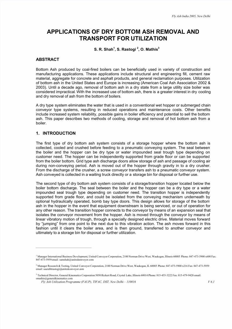
2. DESCRIPTION OF PAX™ PNEUMATIC ASH EXTRACTION SYSTEM
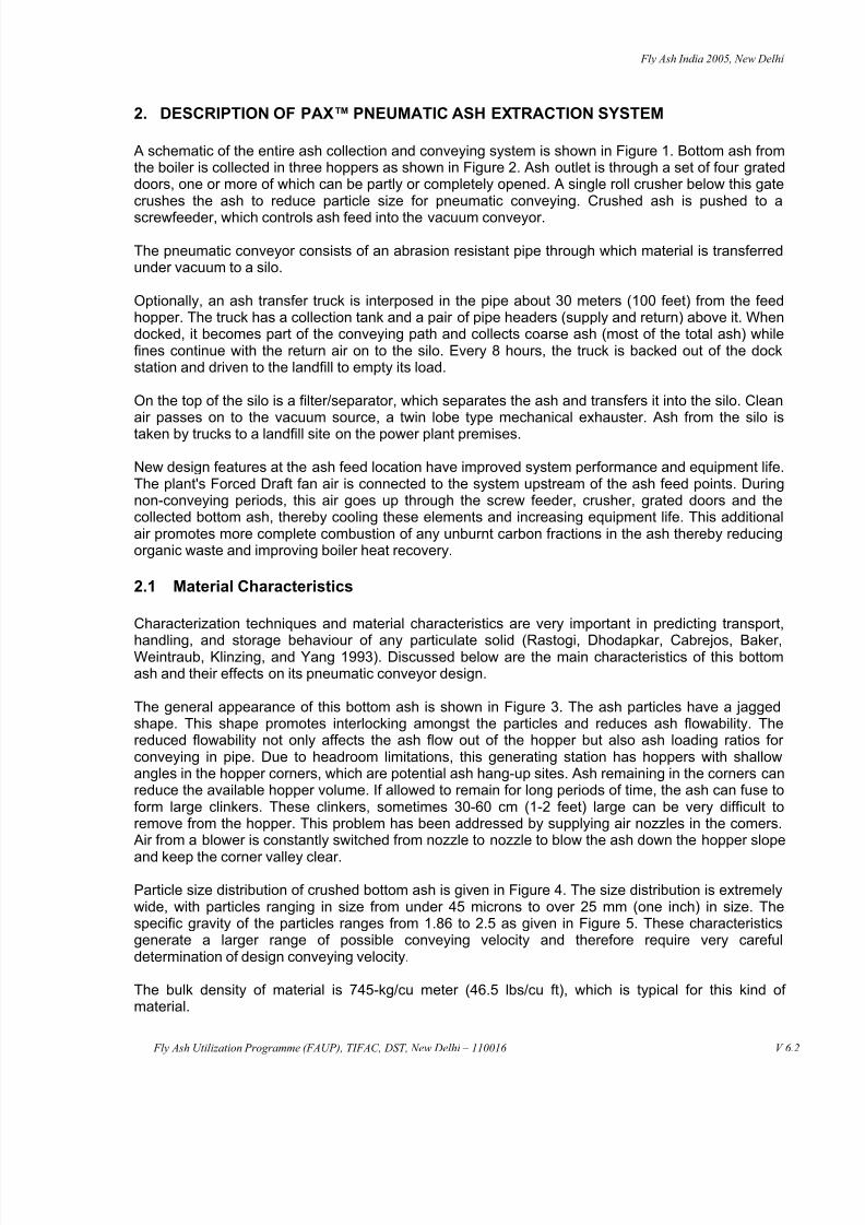
A schematic of the entire ash collection and conveying system is shown in Figure 1. Bottom ash fromthe boiler is collected in three hoppers as shown in Figure 2. Ash outlet is through a set of four grateddoors, one or more of which can be partly or completely opened. A single roll crusher below this gatecrushes the ash to reduce particle size for pneumatic conveying. Crushed ash is pushed to a
screwfeeder, which controls ash feed into the vacuum conveyor.
The pneumatic conveyor consists of an abrasion resistant pipe through which material is transferredunder vacuum to a silo.
Optionally, an ash transfer truck is interposed in the pipe about 30 meters (100 feet) from the feedhopper. The truck has a collection tank and a pair of pipe headers (supply and return) above it. Whendocked, it becomes part of the conveying path and collects coarse ash (most of the total ash) whilefines continue with the return air on to the silo. Every 8 hours, the truck is backed out of the dockstation and driven to the landfill to empty its load.
On the top of the silo is a filter/separator, which separates the ash and transfers it into the silo. Cleanair passes on to the vacuum source, a twin lobe type mechanical exhauster. Ash from the silo is
taken by trucks to a landfill site on the power plant premises.
New design features at the ash feed location have improved system performance and equipment life.The plant's Forced Draft fan air is connected to the system upstream of the ash feed points. Duringnon-conveying periods, this air goes up through the screw feeder, crusher, grated doors and thecollected bottom ash, thereby cooling these elements and increasing equipment life. This additionalair promotes more complete combustion of any unburnt carbon fractions in the ash thereby reducingorganic waste and improving boiler heat recovery.
2.1 Material Characteristics
Characterization techniques and material characteristics are very important in predicting transport,
handling, and storage behaviour of any particulate solid (Rastogi, Dhodapkar, Cabrejos, Baker,Weintraub, Klinzing, and Yang 1993). Discussed below are the main characteristics of this bottomash and their effects on its pneumatic conveyor design.
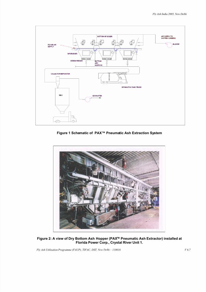
The general appearance of this bottom ash is shown in Figure 3. The ash particles have a jaggedshape. This shape promotes interlocking amongst the particles and reduces ash flowability. Thereduced flowability not only affects the ash flow out of the hopper but also ash loading ratios for conveying in pipe. Due to headroom limitations, this generating station has hoppers with shallowangles in the hopper corners, which are potential ash hang-up sites. Ash remaining in the corners canreduce the available hopper volume. If allowed to remain for long periods of time, the ash can fuse toform large clinkers. These clinkers, sometimes 30-60 cm (1-2 feet) large can be very difficult toremove from the hopper. This problem has been addressed by supplying air nozzles in the comers.Air from a blower is constantly switched from nozzle to nozzle to blow the ash down the hopper slope
and keep the corner valley clear.
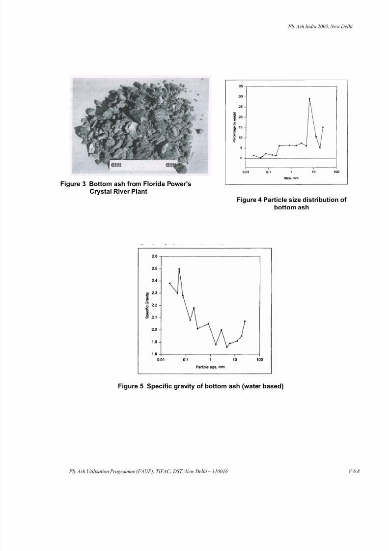
Particle size distribution of crushed bottom ash is given in Figure 4. The size distribution is extremelywide, with particles ranging in size from under 45 microns to over 25 mm (one inch) in size. Thespecific gravity of the particles ranges from 1.86 to 2.5 as given in Figure 5. These characteristicsgenerate a larger range of possible conveying velocity and therefore require very carefuldetermination of design conveying velocity.
The bulk density of material is 745-kg/cu meter (46.5 lbs/cu ft), which is typical for this kind of material.

8/3/2019 006 Transport
http://slidepdf.com/reader/full/006-transport 3/12
Fly Ash India 2005, New Delhi
Fly Ash Utilization Programme (FAUP), TIFAC, DST, New Delhi – 110016 V 6.3
This ash contains 50-70% of combined silica and alumina, which are abrasive components. Toincrease equipment life, AZS or an alumina, zirconia, silica material lining is used in conveying lineelbows installed prior to the ash transfer truck.
2.2 Conveying Velocity
As mentioned above, this material has a wide particle size distribution (Morikawa and Sakamoto1985) (Zenz 1964) and a good spread of particle density. The conveying or pickup velocity should besuch that:
1. System pressure fluctuations do not exceed the capability of the mechanical exhauster.
2. Most of the material is easily accelerated from the feed point.
3. Additional cooling of the material is accomplished in the conveying line.
It is known that in dilute phase pneumatic conveying, as conveying velocity is lowered, systempressure drop reduces up to a certain point (Reed 1990) (Mills 1980). However, as velocity isreduced, system pressure fluctuations are increased. Hence, it is desirable to select the lowestpossible superficial air velocity that enables the system to operate reliably within the pressure
limitations of the prime mover. Additionally with this material, quick acceleration at the feed point isimportant. If the bottom ash is not removed from the feed point fast enough, accumulation andeventual pluggage will occur. Lastly, the pneumatic conveying line allows for additional cooling of thematerial before it enters the ash transfer truck. Effective cooling is accomplished with a dilute phasedensity of approximately 5 kg of ash to 2 kg of air. Extensive laboratory/field testing has indicated apickup velocity around 1800 meters (6000 feet) per minute is required to accomplish the above listedrequirements.
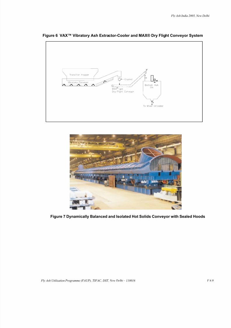
3. DESCRIPTION OF VAX™ VIBRATORY ASH EXTRACTOR SYSTEM
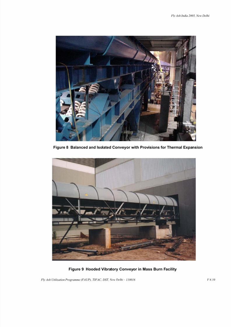
As shown in Figure 6 the VAX (Vibrating Ash Extractor) system consists of a transition hopper locatedbelow the boiler discharge that forms a seal with the boiler. The transition hopper is independentlysupported from grade floor. The refractory lined transition hopper connects to the conveyor by meansof an expansion seal that isolates the conveyor movement from the hopper. The conveyor trough isconstructed of abrasion resistant steel plates, to provide high wear and abrasion resistance along thelength of the conveyor. Material is moved through the conveyor by means of a vibratory motion,introduced through a specially designed electric drive. Material moves forward in a gentle series of “throws and catches” due to this vibration action, which reduces sliding abrasion on the conveyor.The material moves forward in this fashion until it clears the boiler area, and is then either transferredto another conveyor or discharged, as dictated by the equipment arrangement. Photographs inFigures 7, 8 and 9 illustrate typical vibratory conveyor construction.
On the conveyor, any residual pieces of unburnt carbon are allowed to continue the combustionprocess thus recovering heat that would normally be lost in a wet system and therefore contributing tothe boiler efficiency.
The conveyor allows for storage of the bottom ash on the trough section in the event that equipmentdownstream is being serviced, or out of operation for any other reason. Upon resumption of conveying, the material will reliably convey the stored material to the downstream conveyor such asMAX® Dry Flight Conveyor. Additional storage can be provided in the transition hopper by equippingthe hopper with bomb-bay doors.
Before the ash is deposited onto the downstream conveyor a crusher will reduce any oversizedparticles so that the can be conveyed by the secondary mechanical conveyor.

8/3/2019 006 Transport
http://slidepdf.com/reader/full/006-transport 4/12
Fly Ash India 2005, New Delhi
Fly Ash Utilization Programme (FAUP), TIFAC, DST, New Delhi – 110016 V 6.4
3.1 Important Design Characteristics
The vibratory ash extraction and cooling conveyor consists of an ash conveying trough withprovisions for relative thermal expansion and contractions that would be caused by varyingtemperatures of hot gases and bottom ash. The interfacing engineered trough sections incorporateheavy clamped seal plates to enable relative thermal expansion while maintaining seal integrity. The
interface of the upper edges of the ash trough and transition hopper incorporates high temperatureflexible connections to maintain the boiler environment while isolating vibration from the transitionhopper.
To provide for a long wear life, the engineered ash trough deck assemblies are fabricated of thick,abrasion resistant, steel for extended operating life and are independently replaceable, whenrequired, after years of service. Those deck sections beneath the boiler are engineered for impact bylarge clinker pieces whose maximum size, weight, and drop height are determined for each specificinstallation.
The entire trough assembly consisting of the ash trough, plenum assembly and structural frame areconnected to a second structural assembly, the counterbalance, through steel coil reactor springsforming a two mass natural frequency construction. The two masses are driven 180 degrees out of
phase by a common drive assembly, as illustrated in Figure 10, incorporating a fixed eccentric shaftto produce an engineered peak to peak displacement for controlled ash flow rate. A variablefrequency drive is used to adjust the ash conveying rate as required to enable accumulation of ashbeneath the transition hopper and controlled resumption of ash transfer rate to down streamequipment.
3.2 Cooling of Ash
A plenum trough assembly is located beneath the ash-conveying trough to enable controlled, forceddraft, cooling air delivery to the underside of the ash trough. Small holes incorporated in the abrasionresistant trough sections and covered by abrasion resistant formed members produce sufficientpressure drop to uniformly distribute the cooling airflow across the entire ash trough face in plan view.
All cooling air passes completely through the ash bed. This produces intimate, direct gas contact tothe entire bed cross-section, minimizing the amount of cooling air required for the specified ashtemperature drop. If, for any reason, the ash conveyor is operated in the absence of cooling air flowdelivery, any ash fines that may weep into the plenum chamber are conveyed to the end of theconveyor plenum trough and discharged to the receiving equipment down stream while maintainingseal integrity (Figure 11).
Cooling air is supplied to the conveyor plenum assembly by a duct section, supported by and parallelto the stationary conveyor base assembly, incorporating flexible connections along its length. Thecooling airflow is velocity pressure controlled and ambient temperature compensated for adjustablebut controlled mass flow.
4. DESCRIPTION OF PNEUMATIC PRESSURE TRANSPORT SYSTEM
Once the bottom ash has cooled sufficiently, it can be crushed and ground. After proper sizereduction comparable to coarse ash or the fly ash, the bottom ash can be blended with the fly ash in aproper proportion. The blended ash can be sold just like the fly ash.
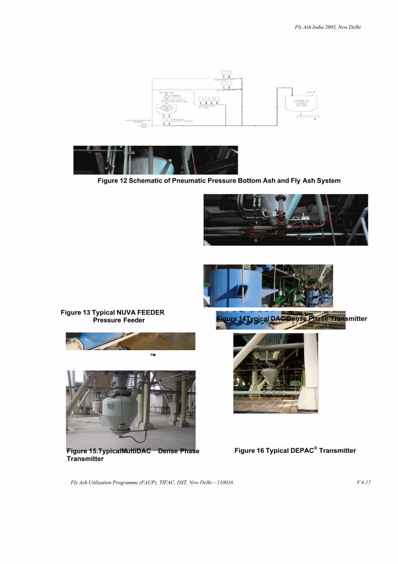
Figure 12 shows a schematic of a positive pressure pneumatic conveyor designed to convey dry free-flowing ash from the Bottom Ash Tank, Economizer Hoppers, Air Preheater and Precipitator hoppersto a large common ash silo. The conveying air is supplied from a blower or a compressor, whichproduces motive airflow into which ash is fed for transport to the common ash silo.

8/3/2019 006 Transport
http://slidepdf.com/reader/full/006-transport 5/12
Fly Ash India 2005, New Delhi
Fly Ash Utilization Programme (FAUP), TIFAC, DST, New Delhi – 110016 V 6.5
4.1 Dilute Phase System
A dilute phase high velocity pneumatic system is a more appropriate solution, where both the groundbottom ash and the economizer ash are coarse and have poor fluidizability. Dilute phase system canconvey fine and coarse particles over a relatively longer distance.
The Bottom ash and Economizer ash are collected continuously in the Bottom Ash Tank andEconomizer hoppers, respectively. Two or more numbers of NUVA FEEDER pressure feeder assemblies are located under Bottom Ash Tank and Economizer hoppers respectively and they areconnected to a single branch line. A NUVA FEEDER pressure feeder assembly, as shown in Figure13, is located under each Air Pre Heater and Precipitator hoppers. The NUVA FEEDER pressurefeeders receives ash from the hoppers above at low-pressure and introduces it into a pressurizedconveying line. Each row of hopper-feeders empties into its respective branch lines, which connect tothe main conveying line. When a system is in operation, the NUVA FEEDER pressure feeder assemblies discharge ash into the conveyor line in a timed sequence. The conveying air and materialis conveyed and discharged into main Ash Silo. The conveying air is vented to atmosphere throughthe Bin Vent Filter.
4.2 Dense Phase System
A low velocity pneumatic dense phase system can be applied for transporting granular coarse ashwith poor fluidizability, however for a relatively shorter distance. Material properties play crucial role indetermining system design parameters. Therefore, at the minimum a designer must have prior knowledge of particle size distribution, maximum particle size, and bulk density.
Beneath each Bottom Ash Tank one or two DAC™ System pressure feeders are located. Dependingon conveyor line configuration DAC, pressure feeders as shown in Figure 14, may or may not beequipped with the discharge valves. In most applications, it will not be appropriate to combine BottomAsh transport pipe lines with the Fly ash transport pipe lines. Bottom ash transport line will beequipped with supplemental air injection ports along its length. Bottom ash from each DAC pressurefeeder shall be conveyed to a combination fly ash and bottom ash silo, or an independent bottom ash
silo when blending of ash is not desired. Economizer ash may be conveyed in the same manner over a shorter distance provided pipe routing constraints are overcome.
Air heater ash and precipitator fly ash particles are considered to be finer and considered easilyfluidizable. Depending on the capacity and transport distance, either MultiDAC™ , as shown in Figure15, or DEPAC
®, low velocity Dense Phase Systems, as shown in Figure 16, can be applied.
5. CONCLUSION
Bottom ash turns in to a valuable resource when it is collected dry, and processed to match the enduse specification. During bottom ash collection and cooling process, heat released migrates up to theboiler, resulting in a heat gain for the boiler. The totally dry ash removal and transport system is moreenvironment friendly, compared to a wet ash removal and transport system.
There are two methods of ash removal from the bottom of the boiler. Pneumatic vacuum system anda mechanical system. Specially engineered primary crusher splinters large clinkers, and a secondstage grinder mill reduces bottom ash to coarse (granular) or fine (powder) sizes, as desired.Technology for a downstream dilute phase ash transport conveyor is well proven. Technology of avery low velocity dense phase coarse ash transport system is relatively new.

8/3/2019 006 Transport
http://slidepdf.com/reader/full/006-transport 6/12
Fly Ash India 2005, New Delhi
Fly Ash Utilization Programme (FAUP), TIFAC, DST, New Delhi – 110016 V 6.6
BIOGRAPHY OF PRIMARY AUTHOR
Sam Shah, Manager International Business Development, United Conveyor Corporation, Illinois.
Received Bachelor of Engineering degree from the S. P. University (India), Master of Businessadministration from the Loyola University of Chicago and has more than 25 years experience in
custom engineered ash and material handling systems.
REFERENCES
American Coal Ash Association, 2002 & 2003 CCP Production & Use Survey, European CoalCombustion Products Association
MILLS, D.: The operational velocity range in pneumatic conveying and its influence on product flowrate; Pneumotransport 5, April 1980, pp. 155-166.
MORIKAWA, Y. and S. SAKAMOTO: Flow characteristics of mixed size particles in horizontalpneumatic conveying; bulk solids handling, Vol. 5, (1985), pp. 61-65.
RASTOGI, S., S.V. DHODAPKAR, F. CABREJOS, J. BAKER, M. WEINTRAUB, G.E. KLINZING, andW.C. YANG: Survey of characterization techniques of dry ultrafine coals and their relationships totransport, handling and storage; Powder Technology, Vol. 74 (1993), pp. 47- 59.
REED, A.R.: Dilute-phase Conveying: Saving Air Means Saving Money; Powder and BulkEngineering, March 1990, pp. 35-36.
ZENZ, F.A.: Conveyability of material of mixed particle size; 1& EC Fundamentals, Vol. 3, (1964), pp.65-75.
8/3/2019 006 Transport
http://slidepdf.com/reader/full/006-transport 7/12
Fly Ash India 2005, New Delhi
Fly Ash Utilization Programme (FAUP), TIFAC, DST, New Delhi – 110016 V 6.7
Figure 2: A view of Dry Bottom Ash Hopper (PAX Pneumatic Ash Extractor) installed atFlorida Power Corp., Crystal River Unit 1.
Figure 1 Schematic of PAX™ Pneumatic Ash Extraction System
8/3/2019 006 Transport
http://slidepdf.com/reader/full/006-transport 8/12
Fly Ash India 2005, New Delhi
Fly Ash Utilization Programme (FAUP), TIFAC, DST, New Delhi – 110016 V 6.8
Figure 3 Bottom ash from Florida Power's
Crystal River Plant
Figure 5 Specific gravity of bottom ash (water based)
Figure 4 Particle size distribution of bottom ash
8/3/2019 006 Transport
http://slidepdf.com/reader/full/006-transport 9/12
Fly Ash India 2005, New Delhi
Fly Ash Utilization Programme (FAUP), TIFAC, DST, New Delhi – 110016 V 6.9
Figure 6 VAX™ Vibratory Ash Extractor-Cooler and MAX® Dry Flight Conveyor System
Figure 7 Dynamically Balanced and Isolated Hot Solids Conveyor with Sealed Hoods
8/3/2019 006 Transport
http://slidepdf.com/reader/full/006-transport 10/12
Fly Ash India 2005, New Delhi
Fly Ash Utilization Programme (FAUP), TIFAC, DST, New Delhi – 110016 V 6.10
Figure 8 Balanced and Isolated Conveyor with Provisions for Thermal Expansion
Figure 9 Hooded Vibratory Conveyor in Mass Burn Facility

8/3/2019 006 Transport
http://slidepdf.com/reader/full/006-transport 11/12
Fly Ash India 2005, New Delhi
Fly Ash Utilization Programme (FAUP), TIFAC, DST, New Delhi – 110016 V 6.11
Figure 10 Dynamically Balanced and Isolated Conveyor Drive
Figure 11 Typical Inclined Conveyor
8/3/2019 006 Transport
http://slidepdf.com/reader/full/006-transport 12/12
Fly Ash India 2005, New Delhi
Fly Ash Utilization Programme (FAUP), TIFAC, DST, New Delhi – 110016 V 6.12
Figure 12 Schematic of Pneumatic Pressure Bottom Ash and Fly Ash System
Figure 14Typical DAC Dense Phase Transmitter Figure 13 Typical NUVA FEEDER
Pressure Feeder
Figure 16 Typical DEPAC ®
Transmitter Figure 15.TypicalMultiDAC Dense PhaseTransmitter