00002 Glenn Dyer Jail Lobby Renovation Specifications …€¦ · PROJECT MANUAL County of Alameda...
84
PROJECT MANUAL County of Alameda GSA Technical Services Department Glenn Dyer Detention Facility Lobby Redesign 550 – 6 th Street, Oakland, California 94607 FINAL SPECIFICATIONS 11 Embarcadero West, Suite 205 Oakland, CA 94607 (510) 538-9991 (510) 327-0312 F AE3 PROJECT # 13-03A July 23, 2013 Book 1 of 1
-
Upload
trinhthuan -
Category
Documents
-
view
213 -
download
0
Transcript of 00002 Glenn Dyer Jail Lobby Renovation Specifications …€¦ · PROJECT MANUAL County of Alameda...

PROJECT MANUAL
County of Alameda GSA Technical Services Department
Glenn Dyer Detention Facility Lobby Redesign
550 – 6th Street, Oakland, California 94607
FINAL SPECIFICATIONS
11 Embarcadero West, Suite 205 Oakland, CA 94607
(510) 538-9991 (510) 327-0312 F
AE3 PROJECT # 13-03A
July 23, 2013
Book 1 of 1


GLENN DYER DETENTION FACILITY LOBBY RENOVATION 100% SUBMITTAL
23 JULY, 2013
Section 00001 Table of Contents page 1 of 2
SECTION 00001 TABLE OF CONTENTS
DIVISION 2 – EXISTING CONDITIONS 024119 Selective Demolition DIVISION 5 – METALS 054000 Cold-Formed Metal Framing DIVISION 6 – WOOD, PLASTICS, AND COMPOSITES 064116 Plastic-Laminate-Faced Architectural Cabinets DIVISION 7 – THERMAL AND MOISTURE PROTECTION 072100 Acoustical Insulation DIVISION 8 – OPENINGS 081113 Hollow Metal Doors and Frames 082110 Bullet Resistant Full Lite Aluminum Door and Frame Assembly 085513 Bullet Resistant 3 Sided Transaction Window DIVISION 9 - FINISHES 092900 Gypsum Board 095123 Acoustical Tile Ceilings 096513 Resilient Base and Accessories 096519 Resilient Tile Flooring 096813 Tile Carpeting 09770 Wall Panel System Application 099123 Interior Painting DIVISION 10 – SPECIALTIES 101423 Panel Signage

GLENN DYER DETENTION FACILITY LOBBY RENOVATION 100% SUBMITTAL
23 JULY, 2013
Section 00001 Table of Contents page 2 of 2
DIVISION 12 - FURNISINGS 123661 Simulated Stone Countertops
DIVISION 13 - SPECIALITY 130700 Bullet Resistant Fiberglass UL752 Level IV (BGAA-04)
DIVISION 26 - LIGHTING 265113 Interior Lighting Fixtures, Lamps, and Ballasts
END OF SECTION

GLENN DYER DETENTION FACILITY LOBBY RENOVATION 100% SUBMITTAL
23 JULY, 2013
SELECTIVE DEMOLITION 024119 - 1
SECTION 024119 - SELECTIVE DEMOLITION
PART 1 - GENERAL
1.1 SUMMARY
A. Section Includes:
1. Demolition and removal of selected portions of building or structure. 2. Demolition and removal of selected site elements. 3. Salvage of existing items to be reused or recycled.
1.2 DEFINITIONS
A. Remove: Detach items from existing construction and legally dispose of them off-site unless indicated to be removed and salvaged or removed and reinstalled.
B. Remove and Salvage: Carefully detach from existing construction, in a manner to prevent damage, and deliver to Owner ready for reuse.
C. Remove and Reinstall: Detach items from existing construction, prepare for reuse, and reinstall where indicated.
D. Existing to Remain: Existing items of construction that are not to be permanently removed and that are not otherwise indicated to be removed, removed and salvaged, or removed and reinstalled.
1.3 PREINSTALLATION MEETINGS
A. Predemolition Conference: Conduct conference at 550 – 6th Street, Oakland, California 94607.
1.4 CLOSEOUT SUBMITTALS
A. Landfill Records: Indicate receipt and acceptance of hazardous wastes by a landfill facility licensed to accept hazardous wastes.
1.5 FIELD CONDITIONS
A. Owner will occupy portions of building immediately adjacent to selective demolition area. Conduct selective demolition so Owner's operations will not be disrupted.
B. Conditions existing at time of inspection for bidding purpose will be maintained by Owner as far as practical.

GLENN DYER DETENTION FACILITY LOBBY RENOVATION 100% SUBMITTAL
23 JULY, 2013
SELECTIVE DEMOLITION 024119 - 2
1. Before selective demolition, Owner will remove the following items:
a. Safe.
b. Computer Equipment.
C. Notify Architect of discrepancies between existing conditions and Drawings before proceeding with selective demolition.
D. Hazardous Materials: It is not expected that hazardous materials will be encountered in the Work.
1. Hazardous materials will be removed by Owner before start of the Work. 2. If suspected hazardous materials are encountered, do not disturb; immediately notify
Architect and Owner. Hazardous materials will be removed by Owner under a separate contract.
E. Storage or sale of removed items or materials on-site is not permitted.
F. Utility Service: Maintain existing utilities indicated to remain in service and protect them against damage during selective demolition operations.
1. Maintain fire-protection facilities in service during selective demolition operations.
1.6 WARRANTY
A. Existing Warranties: Remove, replace, patch, and repair materials and surfaces cut or damaged during selective demolition, by methods and with materials so as not to void existing warranties.
PART 2 - PRODUCTS
2.1 PEFORMANCE REQUIREMENTS
A. Regulatory Requirements: Comply with governing EPA notification regulations before beginning selective demolition. Comply with hauling and disposal regulations of authorities having jurisdiction.
B. Standards: Comply with ANSI/ASSE A10.6 and NFPA 241.
PART 3 - EXECUTION
3.1 EXAMINATION
A. Verify that utilities have been disconnected and capped before starting selective demolition operations.

GLENN DYER DETENTION FACILITY LOBBY RENOVATION 100% SUBMITTAL
23 JULY, 2013
SELECTIVE DEMOLITION 024119 - 3
B. Survey existing conditions and correlate with requirements indicated to determine extent of selective demolition required.
C. When unanticipated mechanical, electrical, or structural elements that conflict with intended function or design are encountered, investigate and measure the nature and extent of conflict. Promptly submit a written report to Architect.
D. Perform an engineering survey of condition of building to determine whether removing any element might result in structural deficiency or unplanned collapse of any portion of structure or adjacent structures during selective building demolition operations.
E. Survey of Existing Conditions: Record existing conditions by use of measured drawings, preconstruction photographs, or preconstruction videotapes.
3.2 UTILITY SERVICES AND MECHANICAL/ELECTRICAL SYSTEMS
A. Existing Services/Systems to Remain: Maintain services/systems indicated to remain and protect them against damage.
B. Existing Services/Systems to Be Removed, Relocated, or Abandoned: Locate, identify, disconnect, and seal or cap off indicated utility services and mechanical/electrical systems serving areas to be selectively demolished.
1. Owner will arrange to shut off indicated services/systems when requested by Contractor. 2. Arrange to shut off indicated utilities with utility companies. 3. If services/systems are required to be removed, relocated, or abandoned, provide
temporary services/systems that bypass area of selective demolition and that maintain continuity of services/systems to other parts of building.
4. Disconnect, demolish, and remove fire-suppression systems, plumbing, and HVAC systems, equipment, and components indicated to be removed.
3.3 PREPARATION
A. Site Access and Temporary Controls: Conduct selective demolition and debris-removal operations to ensure minimum interference with roads, streets, walks, walkways, and other adjacent occupied and used facilities.
B. Temporary Facilities: Provide temporary barricades and other protection required to prevent injury to people and damage to adjacent buildings and facilities to remain.
C. Temporary Shoring: Provide and maintain shoring, bracing, and structural supports as required to preserve stability and prevent movement, settlement, or collapse of construction and finishes to remain, and to prevent unexpected or uncontrolled movement or collapse of construction being demolished.

GLENN DYER DETENTION FACILITY LOBBY RENOVATION 100% SUBMITTAL
23 JULY, 2013
SELECTIVE DEMOLITION 024119 - 4
3.4 SELECTIVE DEMOLITION, GENERAL
A. General: Demolish and remove existing construction only to the extent required by new construction and as indicated. Use methods required to complete the Work within limitations of governing regulations and as follows:
1. Neatly cut openings and holes plumb, square, and true to dimensions required. Use cutting methods least likely to damage construction to remain or adjoining construction. Use hand tools or small power tools designed for sawing or grinding, not hammering and chopping, to minimize disturbance of adjacent surfaces. Temporarily cover openings to remain.
2. Cut or drill from the exposed or finished side into concealed surfaces to avoid marring existing finished surfaces.
3. Do not use cutting torches until work area is cleared of flammable materials. At concealed spaces, such as duct and pipe interiors, verify condition and contents of hidden space before starting flame-cutting operations. Maintain fire watch and portable fire-suppression devices during flame-cutting operations.
4. Locate selective demolition equipment and remove debris and materials so as not to impose excessive loads on supporting walls, floors, or framing.
5. Dispose of demolished items and materials promptly.
B. Reuse of Building Elements: Project has been designed to result in end-of-Project rates for reuse of building elements as follows. Do not demolish building elements beyond what is indicated on Drawings without Architect's approval.
1. Building Structure and Shell: 100 percent.
C. Removed and Salvaged Items:
1. Clean salvaged items. 2. Pack or crate items after cleaning. Identify contents of containers. 3. Store items in a secure area until delivery to Owner. 4. Transport items to Owner's storage area designated by Owner. 5. Protect items from damage during transport and storage.
D. Removed and Reinstalled Items:
1. Clean and repair items to functional condition adequate for intended reuse. 2. Pack or crate items after cleaning and repairing. Identify contents of containers. 3. Protect items from damage during transport and storage. 4. Reinstall items in locations indicated. Comply with installation requirements for new
materials and equipment. Provide connections, supports, and miscellaneous materials necessary to make item functional for use indicated.
E. Existing Items to Remain: Protect construction indicated to remain against damage and soiling during selective demolition. When permitted by Architect, items may be removed to a suitable, protected storage location during selective demolition and cleaned and reinstalled in their original locations after selective demolition operations are complete.

GLENN DYER DETENTION FACILITY LOBBY RENOVATION 100% SUBMITTAL
23 JULY, 2013
SELECTIVE DEMOLITION 024119 - 5
3.5 DISPOSAL OF DEMOLISHED MATERIALS
A. General: Except for items or materials indicated to be recycled, reused, salvaged, reinstalled, or otherwise indicated to remain Owner's property, remove demolished materials from Project site and legally dispose of them in an EPA-approved landfill.
1. Do not allow demolished materials to accumulate on-site. 2. Remove and transport debris in a manner that will prevent spillage on adjacent surfaces
and areas. 3. Remove debris from elevated portions of building by chute, hoist, or other device that
will convey debris to grade level in a controlled descent.
B. Burning: Do not burn demolished materials.
C. Disposal: Transport demolished materials off Owner's property and legally dispose of them.
3.6 CLEANING
A. Clean adjacent structures and improvements of dust, dirt, and debris caused by selective demolition operations. Return adjacent areas to condition existing before selective demolition operations began.
END OF SECTION 024119


GLENN DYER DETENTION FACILITY LOBBY RENOVATION 100% SUBMITTAL
23 JULY, 2013
COLD-FORMED METAL FRAMING 054000 - 1
SECTION 054000 - COLD-FORMED METAL FRAMING
PART 1 - GENERAL
1.1 SUMMARY
A. Section Includes:
1. Exterior non-load-bearing wall framing.
1.2 ACTION SUBMITTALS
A. Product Data: For each type of cold-formed steel framing product and accessory.
B. Shop Drawings:
1. Include layout, spacing, sizes, thicknesses, and types of cold-formed steel framing; fabrication; and fastening and anchorage details, including mechanical fasteners.
2. Indicate reinforcing channels, opening framing, supplemental framing, strapping, bracing, bridging, splices, accessories, connection details, and attachment to adjoining work.
1.3 INFORMATIONAL SUBMITTALS
A. Product test reports.
1.4 QUALITY ASSURANCE
A. Product Tests: Mill certificates or data from a qualified independent testing agency.
PART 2 - PRODUCTS
2.1 PERFORMANCE REQUIREMENTS
A. AISI Specifications and Standards: Unless more stringent requirements are indicated, comply with AISI S100 and AISI S200.
B. Fire-Resistance Ratings: Comply with ASTM E 119; testing by a qualified testing agency.
1. Indicate design designations from UL's "Fire Resistance Directory" or from the listings of another qualified testing agency.

GLENN DYER DETENTION FACILITY LOBBY RENOVATION 100% SUBMITTAL
23 JULY, 2013
COLD-FORMED METAL FRAMING 054000 - 2
2.2 COLD-FORMED STEEL FRAMING, GENERAL
A. Recycled Content of Steel Products: Postconsumer recycled content plus one-half of preconsumer recycled content not less than 25 percent.
B. Steel Sheet: ASTM A 1003/A 1003M, Structural Grade, Type H, metallic coated, of grade and coating weight as follows:
1. Grade: ST33H 2. Coating: G60
C. Steel Sheet for Vertical Deflection Clips: ASTM A 653/A 653M, structural steel, zinc coated, of grade and coating as follows:
1. Grade: 33. 2. Coating: G60
2.3 NON-LOAD-BEARING WALL FRAMING
A. Steel Studs: Manufacturer's standard C-shaped steel studs, of web depths indicated, punched, with stiffened flanges, and as follows:
1. Minimum Base-Metal Thickness: 0.0538 (54-mil). 2. Flange Width: 1-5/8 inches.
B. Steel Track: Manufacturer's standard U-shaped steel track, of web depths indicated, unpunched, with unstiffened flanges, and matching minimum base-metal thickness of steel studs.
C. Single Deflection Track: Manufacturer's single, deep-leg, U-shaped steel track; unpunched, with unstiffened flanges, of web depth to contain studs while allowing free vertical movement, with flanges designed to support horizontal loads and transfer them to the primary structure.
2.4 FRAMING ACCESSORIES
A. Fabricate steel-framing accessories from steel sheet, ASTM A 1003/A 1003M, Structural Grade, Type H, metallic coated, of same grade and coating weight used for framing members.
B. Provide accessories of manufacturer's standard thickness and configuration.
2.5 ANCHORS, CLIPS, AND FASTENERS
A. Expansion Anchors: Fabricated from corrosion-resistant materials, with allowable load or strength design capacities calculated according to ICC-ES AC193 and ACI 318 greater than or equal to the design load, as determined by testing per ASTM E 488 conducted by a qualified testing agency.
B. Power-Actuated Anchors: Fastener system of type suitable for application indicated, fabricated from corrosion-resistant materials, with allowable load capacities calculated according to ICC-

GLENN DYER DETENTION FACILITY LOBBY RENOVATION 100% SUBMITTAL
23 JULY, 2013
COLD-FORMED METAL FRAMING 054000 - 3
ES AC70, greater than or equal to the design load, as determined by testing per ASTM E 1190 conducted by a qualified testing agency.
C. Mechanical Fasteners: ASTM C 1513, corrosion-resistant-coated, self-drilling, self-tapping, steel drill screws.
1. Head Type: Low-profile head beneath sheathing, manufacturer's standard elsewhere.
2.6 MISCELLANEOUS MATERIALS
A. Galvanizing Repair Paint: ASTM A 780.
B. Cement Grout: Portland cement, ASTM C 150, Type I; and clean, natural sand, ASTM C 404. Mix at ratio of 1 part cement to 2-1/2 parts sand, by volume, with minimum water required for placement and hydration.
C. Nonmetallic, Nonshrink Grout: Premixed, nonmetallic, noncorrosive, nonstaining grout containing selected silica sands, portland cement, shrinkage-compensating agents, and plasticizing and water-reducing agents, complying with ASTM C 1107/C 1107M, with fluid consistency and 30-minute working time.
D. Shims: Load bearing, high-density multimonomer plastic, and nonleaching; or of cold-formed steel of same grade and coating as framing members supported by shims.
E. Sealer Gaskets: Closed-cell neoprene foam, 1/4 inch thick, selected from manufacturer's standard widths to match width of bottom track or rim track members.
PART 3 - EXECUTION
3.1 PREPARATION
A. Install load bearing shims or grout between the underside of load-bearing wall bottom track and the top of foundation wall or slab at locations with a gap larger than 1/4 inch to ensure a uniform bearing surface on supporting concrete or masonry construction.
B. Install sealer gaskets at the underside of wall bottom track or rim track and at the top of foundation wall or slab at stud or joist locations.
3.2 INSTALLATION, GENERAL
A. Cold-formed steel framing may be shop or field fabricated for installation, or it may be field assembled.
B. Install cold-formed steel framing according to AISI S200 and to manufacturer's written instructions unless more stringent requirements are indicated.

GLENN DYER DETENTION FACILITY LOBBY RENOVATION 100% SUBMITTAL
23 JULY, 2013
COLD-FORMED METAL FRAMING 054000 - 4
C. Install cold-formed steel framing and accessories plumb, square, and true to line, and with connections securely fastened.
D. Install framing members in one-piece lengths.
E. Install temporary bracing and supports to secure framing and support loads comparable in intensity to those for which structure was designed. Maintain braces and supports in place, undisturbed, until entire integrated supporting structure has been completed and permanent connections to framing are secured.
F. Install insulation, specified in Section 072100 "Thermal Insulation," in built-up exterior framing members, such as headers, sills, boxed joists, and multiple studs at openings, that are inaccessible on completion of framing work.
G. Fasten hole reinforcing plate over web penetrations that exceed size of manufacturer's approved or standard punched openings.
H. Erection Tolerances: Install cold-formed steel framing level, plumb, and true to line to a maximum allowable tolerance variation of 1/8 inch in 10 feet and as follows:
1. Space individual framing members no more than plus or minus 1/8 inch from plan location. Cumulative error shall not exceed minimum fastening requirements of sheathing or other finishing materials.
3.3 NON-LOAD-BEARING WALL INSTALLATION
A. Install continuous tracks sized to match studs. Align tracks accurately and securely anchor to supporting structure as indicated.
B. Fasten both flanges of studs to bottom track unless otherwise indicated. Space studs as follows:
1. Stud Spacing: As indicated.
C. Set studs plumb, except as needed for diagonal bracing or required for nonplumb walls or warped surfaces and similar requirements.
D. Isolate non-load-bearing steel framing from building structure to prevent transfer of vertical loads while providing lateral support.
1. Install single deep-leg deflection tracks and anchor to building structure. 2. Connect drift clips to cold-formed metal framing and anchor to building structure.
E. Install horizontal bridging in wall studs, spaced vertically in not more than 48 inches apart. Fasten at each stud intersection.
1. Top Bridging for Single Deflection Track: Install row of horizontal bridging within 12 inches of single deflection track. Install a combination of bridging and stud or stud-track solid blocking of width and thickness matching studs, secured to stud webs or flanges.

GLENN DYER DETENTION FACILITY LOBBY RENOVATION 100% SUBMITTAL
23 JULY, 2013
COLD-FORMED METAL FRAMING 054000 - 5
a. Install solid blocking at mid-height of studs.
2. Bridging: Cold-rolled steel channel, welded or mechanically fastened to webs of punched studs.
3. Bridging: Combination of flat, taut, steel sheet straps of width and thickness indicated and stud-track solid blocking of width and thickness to match studs. Fasten flat straps to stud flanges and secure solid blocking to stud webs or flanges.
4. Bridging: Proprietary bridging bars installed according to manufacturer's written instructions.
F. Install miscellaneous framing and connections, including stud kickers, web stiffeners, clip angles, continuous angles, anchors, and fasteners, to provide a complete and stable wall-framing system.
3.4 REPAIRS AND PROTECTION
A. Galvanizing Repairs: Prepare and repair damaged galvanized coatings on fabricated and installed cold-formed steel framing with galvanized repair paint according to ASTM A 780 and manufacturer's written instructions.
B. Provide final protection and maintain conditions, in a manner acceptable to manufacturer and Installer, that ensure that cold-formed steel framing is without damage or deterioration at time of Substantial Completion.
END OF SECTION 054000

GLENN DYER DETENTION FACILITY LOBBY RENOVATION 100% SUBMITTAL
23 JULY, 2013
PLASTIC-LAMINATE-FACED ARCHITECTURAL CABINETS 064116 - 1
SECTION 064116 - PLASTIC-LAMINATE-FACED ARCHITECTURAL CABINETS
PART 1 - GENERAL
1.1 SUMMARY
A. Section Includes:
1. Plastic-laminate-faced architectural cabinets. 2. Wood furring, blocking, shims, and hanging strips for installing plastic-laminate-faced
architectural cabinets unless concealed within other construction before cabinet installation.
1.2 ACTION SUBMITTALS
A. Product Data: For each type of product, including panel products, high-pressure decorative laminate, and cabinet hardware and accessories.
B. LEED Submittals:
1. Laboratory Test Reports for Credit IEQ 4.1: For adhesives, documentation indicating
that products comply with the testing and product requirements of the California Department of Health Services' "Standard Practice for the Testing of Volatile Organic Emissions from Various Sources Using Small-Scale Environmental Chambers."
2. Product Data for Credit IEQ 4.4: For adhesives and composite wood products, documentation indicating that products contain no urea formaldehyde.
3. Laboratory Test Reports for Credit IEQ 4.4: For composite wood products, documentation indicating that products comply with the testing and product requirements of the California Department of Health Services' "Standard Practice for the Testing of Volatile Organic Emissions from Various Sources Using Small-Scale Environmental Chambers."
C. Shop Drawings: Show location of each item, dimensioned plans and elevations, large-scale details, attachment devices, and other components.
D. Samples:
1. Plastic laminates, for each color, pattern, and surface finish.

GLENN DYER DETENTION FACILITY LOBBY RENOVATION 100% SUBMITTAL
23 JULY, 2013
PLASTIC-LAMINATE-FACED ARCHITECTURAL CABINETS 064116 - 2
1.3 FIELD CONDITIONS
A. Environmental Limitations: Do not deliver or install cabinets until building is enclosed, wet work is complete, and HVAC system is operating and maintaining temperature and relative humidity at occupancy levels during the remainder of the construction period.
PART 2 - PRODUCTS
2.1 PLASTIC-LAMINATE-FACED ARCHITECTURAL CABINETS
A. Quality Standard: Unless otherwise indicated, comply with the "Architectural Woodwork Standards" for grades of architectural plastic-laminate cabinets indicated for construction, finishes, installation, and other requirements.
B. Grade: Economy.
C. Type of Construction: Frameless.
D. Cabinet, Door, and Drawer Front Interface Style: Flush overlay
E. High-Pressure Decorative Laminate: NEMA LD 3, grades as indicated or if not indicated, as required by woodwork quality standard.
1. Manufacturers: Subject to compliance with requirements, available manufacturers offering products that may be incorporated into the Work include, but are not limited to, the following:
a. Abet Laminati, Inc. b. Formica Corporation. c. Lamin-Art, Inc. d. Panolam Industries International, Inc. e. Wilsonart International; Div. of Premark International, Inc.
F. Laminate Cladding for Exposed Surfaces:
1. Horizontal Surfaces: Grade HGS 2. Postformed Surfaces: Grade HGP. 3. Vertical Surfaces: Grade HGS 4. Pattern Direction: Vertically for drawer fronts, doors, and fixed panels
G. Materials for Semiexposed Surfaces:
1. Surfaces Other Than Drawer Bodies: High-pressure decorative laminate, NEMA LD 3, Grade VGS
2. Drawer Sides and Backs: Thermoset decorative panels with PVC or polyester edge banding.
3. Drawer Bottoms: Thermoset decorative panels.

GLENN DYER DETENTION FACILITY LOBBY RENOVATION 100% SUBMITTAL
23 JULY, 2013
PLASTIC-LAMINATE-FACED ARCHITECTURAL CABINETS 064116 - 3
H. Dust Panels: 1/4-inch plywood or tempered hardboard above compartments and drawers unless located directly under tops.
I. Colors, Patterns, and Finishes: Provide materials and products that result in colors and textures of exposed laminate surfaces complying with the following requirements:
1. As selected by Architect from laminate manufacturer's full range in the following
categories:
a. Cabinetry: Solid colors, white, matte finish.
b. Quartz counter trim: Solid colors, black, matte finish.
2.2 WOOD MATERIALS
A. Wood Products: Provide materials that comply with requirements of referenced quality standard for each type of woodwork and quality grade specified unless otherwise indicated.
1. Wood Moisture Content: 5 to 10 percent.
B. Composite Wood and Agrifiber Products: Provide materials that comply with requirements of referenced quality standard for each type of woodwork and quality grade specified unless otherwise indicated.
1. Recycled Content of Medium-Density Fiberboard and Particleboard: Postconsumer recycled content plus one-half of preconsumer recycled content not less than 40 percent.
2. Composite Wood and Agrifiber Products: Products shall comply with the testing and product requirements of the California Department of Health Services' "Standard Practice for the Testing of Volatile Organic Emissions from Various Sources Using Small-Scale Environmental Chambers."
3. Medium-Density Fiberboard: ANSI A208.2, Grade 130, made with binder containing no urea formaldehyde.
2.3 CABINET HARDWARE AND ACCESSORIES
A. General: Provide cabinet hardware and accessory materials associated with architectural cabinets.
B. Hinges:
1. Semiconcealed Hinges for Flush Doors: BHMA A156.9, B01361.
C. Frameless Concealed Hinges (European Type): BHMA A156.9, B01602, 135 degrees of opening.
D. Wire Pulls: Back mounted, solid metal, 4 inches long.

GLENN DYER DETENTION FACILITY LOBBY RENOVATION 100% SUBMITTAL
23 JULY, 2013
PLASTIC-LAMINATE-FACED ARCHITECTURAL CABINETS 064116 - 4
E. Adjustable Shelf Standards and Supports: BHMA A156.9, B04071; with shelf rests, B04081.
F. Shelf Rests: BHMA A156.9, B04013; metal, two-pin type with shelf hold-down clip.
G. Door Silencers: BHMA A156.16, L03011.
H. Exposed Hardware Finishes: For exposed hardware, provide finish that complies with BHMA A156.18 for BHMA finish number indicated.
1. Satin Stainless Steel: BHMA 630.
2.4 MISCELLANEOUS MATERIALS
A. Furring, Blocking, Shims, and Hanging Strips: Softwood or hardwood lumber, kiln dried to less than 15 percent moisture content.
B. Anchors: Select material, type, size, and finish required for each substrate for secure anchorage. Provide metal expansion sleeves or expansion bolts for post-installed anchors. Use nonferrous-metal or hot-dip galvanized anchors and inserts at inside face of exterior walls and at floors.
C. Adhesives: Do not use adhesives that contain urea formaldehyde.
D. Adhesives: Use adhesives that meet the testing and product requirements of the California Department of Health Services' "Standard Practice for the Testing of Volatile Organic Emissions from Various Sources Using Small-Scale Environmental Chambers."
E. Adhesive for Bonding Plastic Laminate: Unpigmented contact cement
1. Adhesive for Bonding Edges: Hot-melt adhesive or adhesive specified above for faces
2.5 FABRICATION
A. Complete fabrication, including assembly and hardware application, to maximum extent possible before shipment to Project site. Disassemble components only as necessary for shipment and installation. Where necessary for fitting at site, provide ample allowance for scribing, trimming, and fitting.
B. Shop-cut openings to maximum extent possible to receive hardware, appliances, electrical work, and similar items. Locate openings accurately and use templates or roughing-in diagrams to produce accurately sized and shaped openings. Sand edges of cutouts to remove splinters and burrs.

GLENN DYER DETENTION FACILITY LOBBY RENOVATION 100% SUBMITTAL
23 JULY, 2013
PLASTIC-LAMINATE-FACED ARCHITECTURAL CABINETS 064116 - 5
PART 3 - EXECUTION
3.1 PREPARATION
A. Before installation, condition cabinets to average prevailing humidity conditions in installation areas.
3.2 INSTALLATION
A. Grade: Install cabinets to comply with same grade as item to be installed.
B. Install cabinets level, plumb, true, and straight. Shim as required with concealed shims. Install level and plumb to a tolerance of 1/8 inch in 96 inches
C. Scribe and cut cabinets to fit adjoining work, refinish cut surfaces, and repair damaged finish at cuts.
D. Anchor cabinets to anchors or blocking built in or directly attached to substrates. Secure with countersunk, concealed fasteners and blind nailing. Use fine finishing nails or finishing screws for exposed fastening, countersunk and filled flush with woodwork.
E. Cabinets: Install without distortion so doors and drawers fit openings properly and are accurately aligned. Adjust hardware to center doors and drawers in openings and to provide unencumbered operation. Complete installation of hardware and accessory items as indicated.
1. Install cabinets with no more than 1/8 inch in 96-inch sag, bow, or other variation from a straight line.
2. Fasten wall cabinets through back, near top and bottom, and at ends not more than 16 inches o.c.
END OF SECTION 064116


GLENN DYER DETENTION FACILITY LOBBY RENOVATION 100% SUBMITTAL
23 JULY, 2013
THERMAL INSULATION 072100 - 1
SECTION 072100 – ACOUSTICAL INSULATION
PART 1 - GENERAL
1.1 SUMMARY
A. Section Includes:
1. Glass-fiber blanket acoustical insulation.
1.2 ACTION SUBMITTALS
A. Product Data: For each type of product indicated.
1.3 INFORMATIONAL SUBMITTALS
A. Product test reports.
B. Research/evaluation reports.
PART 2 - PRODUCTS
2.1 GLASS-FIBER BLANKET ACOUSTICAL INSULATION
A. Manufacturers: Subject to compliance with requirements, available manufacturers offering products that may be incorporated into the Work include, but are not limited to, the following:
1. CertainTeed Corporation. 2. Guardian Building Products, Inc. 3. Johns Manville. 4. Knauf Insulation. 5. Owens Corning.
B. Recycled Content: Postconsumer recycled content plus one-half of preconsumer recycled content not less than 25 percent.
C. Unfaced, Glass-Fiber Blanket Insulation: ASTM C 665, Type I; with maximum flame-spread and smoke-developed indexes of 25 and 50, respectively, per ASTM E 84; passing ASTM E 136 for combustion characteristics.
D. Sound Transmission Class: STC 35 min.
GLENN DYER DETENTION FACILITY LOBBY RENOVATION 100% SUBMITTAL
23 JULY, 2013
THERMAL INSULATION 072100 - 2
PART 3 - EXECUTION
3.1 INSTALLATION, GENERAL
A. Comply with insulation manufacturer's written instructions applicable to products and applications indicated.
B. Install insulation that is undamaged, dry, and unsoiled and that has not been left exposed to ice, rain, or snow at any time.
C. Extend insulation to envelop entire area to be insulated. Cut and fit tightly around obstructions and fill voids with insulation. Remove projections that interfere with placement.
D. Provide sizes to fit applications indicated and selected from manufacturer's standard thicknesses, widths, and lengths. Apply single layer of insulation units to produce thickness indicated unless multiple layers are otherwise shown or required to make up total thickness.
3.2 INSTALLATION OF INSULATION FOR FRAMED CONSTRUCTION
A. Glass-Fiber or Mineral-Wool Blanket Insulation: Install in cavities formed by framing members according to the following requirements:
1. Use insulation widths and lengths that fill the cavities formed by framing members. If more than one length is required to fill the cavities, provide lengths that will produce a snug fit between ends.
2. Place insulation in cavities formed by framing members to produce a friction fit between edges of insulation and adjoining framing members.
3. Maintain 3-inch clearance of insulation around recessed lighting fixtures not rated for or protected from contact with insulation.
4. For metal-framed wall cavities where cavity heights exceed 96 inches (2438 mm), support unfaced blankets mechanically and support faced blankets by taping flanges of insulation to flanges of metal studs.
END OF SECTION 072100

GLENN DYER DETENTION FACILITY LOBBY RENOVATION 100% SUBMITTAL
23 JULY, 2013
HOLLOW METAL DOORS AND FRAMES 081113 - 1
SECTION 081113 - HOLLOW METAL DOORS AND FRAMES
PART 1 - GENERAL
1.1 SUMMARY
A. Section includes hollow-metal work.
1.2 DEFINITIONS
A. Minimum Thickness: Minimum thickness of base metal without coatings according to NAAMM-HMMA 803 or SDI A250.8.
1.3 ACTION SUBMITTALS
A. Product Data: For each type of product.
PART 2 - PRODUCTS
2.1 MANUFACTURERS
A. Manufacturers: Subject to compliance with requirements, available manufacturers offering products that may be incorporated into the Work include, but are not limited to, the following:
1. Amweld International, LLC. 2. Apex Industries, Inc. 3. Ceco Door Products; an Assa Abloy Group company. 4. Commercial Door & Hardware Inc. 5. Concept Frames, Inc. 6. Curries Company; an Assa Abloy Group company. 7. Custom Metal Products. 8. Daybar. 9. Deansteel. 10. de La Fontaine Industries. 11. DKS Steel Door & Frame Sys. Inc. 12. Door Components, Inc. 13. Fleming-Baron Door Products. 14. Gensteel Doors Inc. 15. Greensteel Industries, Ltd. 16. HMF Express. 17. Hollow Metal Inc. 18. Hollow Metal Xpress. 19. J/R Metal Frames Manufacturing, Inc.
GLENN DYER DETENTION FACILITY LOBBY RENOVATION 100% SUBMITTAL
23 JULY, 2013
HOLLOW METAL DOORS AND FRAMES 081113 - 2
20. Karpen Steel Custom Doors & Frames. 21. L.I.F. Industries, Inc. 22. LaForce, Inc. 23. Megamet Industries, Inc. 24. Mesker Door Inc. 25. Michbi Doors Inc. 26. MPI Group, LLC (The). 27. National Custom Hollow Metal. 28. North American Door Corp. 29. Philipp Manufacturing Co (The). 30. Pioneer Industries, Inc. 31. Premier Products, Inc. 32. Republic Doors and Frames. 33. Rocky Mountain Metals, Inc. 34. Security Metal Products Corp. 35. Shanahans Manufacturing Ltd. 36. Steelcraft; an Ingersoll-Rand company. 37. Steward Steel; Door Division. 38. Stiles Custom Metal, Inc. 39. Titan Metal Products, Inc. 40. Trillium Steel Doors Limited. 41. West Central Mfg. Inc.
2.2 INTERIOR DOORS AND FRAMES
A. Standard-Duty Doors and Frames: SDI A250.8, Level 1. At locations indicated on the drawings
1. Physical Performance: Level C according to SDI A250.4. 2. Doors:
a. Type: as indicated on the drawings. b. Thickness: 1-3/4 inches c. Face: Uncoated, cold-rolled steel sheet, minimum thickness of 0.032 inch d. Edge Construction: Model 1, Full Flush e. Core: Manufacturer's standard
3. Frames:
a. Materials: Uncoated, cold-rolled steel sheet, minimum thickness of 0.042 inch b. Construction: Knocked down
4. Exposed Finish: Factory.
2.3 FRAME ANCHORS
A. Jamb Anchors:

GLENN DYER DETENTION FACILITY LOBBY RENOVATION 100% SUBMITTAL
23 JULY, 2013
HOLLOW METAL DOORS AND FRAMES 081113 - 3
1. Stud-Wall Type: Designed to engage stud, welded to back of frames; not less than 0.042 inch thick.
2.4 MATERIALS
A. Cold-Rolled Steel Sheet: ASTM A 1008/A 1008M, Commercial Steel (CS), Type B; suitable for exposed applications.
B. Frame Anchors: ASTM A 879/A 879M, Commercial Steel (CS), 04Z coating designation; mill phosphatized.
C. Inserts, Bolts, and Fasteners: Hot-dip galvanized according to ASTM A 153/A 153M.
D. Power-Actuated Fasteners in Concrete: From corrosion-resistant materials.
E. Grout: ASTM C 476, except with a maximum slump of 4 inches, as measured according to ASTM C 143/C 143M.
F. Mineral-Fiber Insulation: ASTM C 665, Type I (blankets without membrane facing).
G. Bituminous Coating: Cold-applied asphalt mastic, compounded for 15-mil dry film thickness per coat.
2.5 FABRICATION
A. Fabricate hollow-metal work to be rigid and free of defects, warp, or buckle. Accurately form metal to required sizes and profiles, with minimum radius for metal thickness. Where practical, fit and assemble units in manufacturer's plant. To ensure proper assembly at Project site, clearly identify work that cannot be permanently factory assembled before shipment.
B. Hollow-Metal Frames: Where frames are fabricated in sections due to shipping or handling limitations, provide alignment plates or angles at each joint, fabricated of same thickness metal as frames.
1. Provide countersunk, flat- or oval-head exposed screws and bolts for exposed fasteners
unless otherwise indicated. 2. Grout Guards: Weld guards to frame at back of hardware mortises in frames to be
grouted. 3. Jamb Anchors: Provide number and spacing of anchors as follows:
a. Stud-Wall Type: Locate anchors not more than 18 inches from top and bottom of frame. Space anchors not more than 32 inches o.c. and as follows:
1) Three anchors per jamb up to 60 inches high. 2) Four anchors per jamb from 60 to 90 inches high. 3) Five anchors per jamb from 90 to 96 inches high.

GLENN DYER DETENTION FACILITY LOBBY RENOVATION 100% SUBMITTAL
23 JULY, 2013
HOLLOW METAL DOORS AND FRAMES 081113 - 4
4) Five anchors per jamb plus one additional anchor per jamb for each 24 inches or fraction thereof above 96 inches high.
4. Door Silencers: Except on weather-stripped frames, drill stops to receive door silencers.
a. Single-Door Frames: Drill stop in strike jamb to receive three door silencers.
C. Hardware Preparation: Factory prepare hollow-metal work to receive templated mortised hardware; include cutouts, reinforcement, mortising, drilling, and tapping according to SDI A250.6, the Door Hardware Schedule, and templates.
1. Reinforce doors and frames to receive nontemplated, mortised, and surface-mounted door hardware.
2. Comply with applicable requirements in SDI A250.6 and BHMA A156.115 for preparation of hollow-metal work for hardware.
2.6 STEEL FINISHES
A. Prime Finish: Clean, pretreat, and apply manufacturer's standard primer.
1. Shop Primer: SDI A250.10.
B. Factory Finish: SDI A250.3.
1. Color and Gloss: As selected by Architect from manufacturer's full range
PART 3 - EXECUTION
3.1 INSTALLATION
A. Hollow-Metal Frames: Install hollow-metal frames of size and profile indicated. Comply with SDI A250.11 or NAAMM-HMMA 840 as required by standards specified.
1. Set frames accurately in position; plumbed, aligned, and braced securely until permanent anchors are set. After wall construction is complete, remove temporary braces, leaving surfaces smooth and undamaged. a. Where frames are fabricated in sections because of shipping or handling
limitations, field splice at approved locations by welding face joint continuously; grind, fill, dress, and make splice smooth, flush, and invisible on exposed faces.
b. Install frames with removable stops located on secure side of opening. c. Install door silencers in frames before grouting. d. Remove temporary braces necessary for installation only after frames have been
properly set and secured. e. Check plumb, square, and twist of frames as walls are constructed. Shim as
necessary to comply with installation tolerances.

GLENN DYER DETENTION FACILITY LOBBY RENOVATION 100% SUBMITTAL
23 JULY, 2013
HOLLOW METAL DOORS AND FRAMES 081113 - 5
f. Field apply bituminous coating to backs of frames that will be filled with grout containing antifreezing agents.
2. In-Place Metal or Wood-Stud Partitions: Secure slip-on drywall frames in place according to manufacturer's written instructions.
3. Installation Tolerances: Adjust hollow-metal door frames for squareness, alignment, twist, and plumb to the following tolerances:
a. Squareness: Plus or minus 1/16 inch, measured at door rabbet on a line 90 degrees from jamb perpendicular to frame head.
b. Alignment: Plus or minus 1/16 inch, measured at jambs on a horizontal line parallel to plane of wall.
c. Twist: Plus or minus 1/16 inch, measured at opposite face corners of jambs on parallel lines, and perpendicular to plane of wall.
d. Plumbness: Plus or minus 1/16 inch, measured at jambs at floor.
B. Hollow-Metal Doors: Fit hollow-metal doors accurately in frames, within clearances specified below. Shim as necessary.
1. Non-Fire-Rated Steel Doors:
a. Between Door and Frame Jambs and Head: 1/8 inch plus or minus 1/32 inch. b. Between Edges of Pairs of Doors: 1/8 inch to 1/4 inch plus or minus 1/32 inch. c. At Bottom of Door: 5/8 inch plus or minus 1/32 inch . d. Between Door Face and Stop: 1/16 inch to 1/8 inch plus or minus 1/32 inch.
3.2 ADJUSTING AND CLEANING
A. Final Adjustments: Check and readjust operating hardware items immediately before final inspection. Leave work in complete and proper operating condition. Remove and replace defective work, including hollow-metal work that is warped, bowed, or otherwise unacceptable.
B. Remove grout and other bonding material from hollow-metal work immediately after installation.
C. Prime-Coat Touchup: Immediately after erection, sand smooth rusted or damaged areas of prime coat and apply touchup of compatible air-drying, rust-inhibitive primer.
D. Metallic-Coated Surface Touchup: Clean abraded areas and repair with galvanizing repair paint according to manufacturer's written instructions.
E. Touchup Painting: Cleaning and touchup painting of abraded areas of paint are specified in painting Sections.
END OF SECTION 081113


GLENN DYER DETENTION FACILITY LOBBY RENOVATION 100% SUBMITTAL
23 JULY, 2013
SECTION 082110 – BULLET RESISTANT FULL LITE ALUMINUM DOOR AND FRAME ASSEMBLY
Cross Reference: Section 085513 – Bullet Resistant 3 Sided Transaction Window Section 130700 – Bullet Resistant Fiberglass UL 752 Level IV (BGAA-04)
Part 1
1.1 REFERENCE The publications listed below form a part of this specification. NATIONAL INSTITUTE OF JUSTICE STANDARD 0108.01-STANDARD FOR BALLISTIC RESISTANT PROTECTIVE MATERIALS (September, 1985). UNDERWRITERS LABORATORY UL 752 9th edition, Standard for Bullet Resisting Equipment (January, 1995).
1.2 SUBMITTALS Submit for approval prior to fabrication samples, brochures, shop drawings, specifications, UL listing and UL 752 Current Test Results as provided by Underwriters Laboratory and printed data in sufficient detail to indicate compliance with the contract documents. Manufacturer’s instructions for installation of Bullet Resistant Door and Frame Assembly.
1.3 DESIGN Through design, manufacturing technique and material application, door and frame shall be rated by manufacturer to be bullet resistant UL-752 Level 4. The door and frame must be manufactured by the same firm. Door and frame shall be prepped for hardware by the manufacturer in accordance with the approved hardware schedule.
1.4 WARRANTY All materials and workmanship shall be warranted against defects for a period of two (2) years from date of receipt at job site.
Part 2
2.1 MANUFACTURER The door and frame to be manufactured as indicated on the approved drawings by Bullet Guard Corporation, West Sacramento, CA. 1-800-233-5632. www.bulletguard.com

GLENN DYER DETENTION FACILITY LOBBY RENOVATION 100% SUBMITTAL
23 JULY, 2013
2.2 DOOR Bullet resistant full lite door shall be made of aluminum 6063 Alloy with a minimum of .125” thick. The door shall be welded together at all corners. Clipped or fastened together in lieu of welding is not acceptable. Door unit shall be supplied pre-hung with a Roton Continuous Gear Hinge and hung in a aluminum ballistic capture frame system. Includes UL-752 Level 4 bullet resistant no spall, glass clad polycarbonate required for door vision panels, they shall be standard products furnished by the door manufacturer and must be a UL Listed material of specified level. Doors to be pre-glazed at the manufacturer’s facility. No glazing can take place at the job site.
2.3 FRAME
Frame shall be a protection level equal to the door. Frame shall be a “non-ricochet type” design made of aluminum or steel as specified in the approved plans. Frame shall have a powder coat finish for durability. Standard manufacturing tolerances of +/- 1/16” apply.
Part 3
3.1 INSTALLATION In accordance with manufacturer’s instructions.
3.2 PROTECTION
It shall be the responsibility of the contractor to see that any scratches or damage caused in shipping or handling of the products are properly cleaned and touched up. Store the products in a dry, heated location, covered and ventilated to protect them from damage. Repair damaged units prior to completion and acceptance of the project or replace with new, as directed.
3.3 CLEANING
Upon completion, clean units thoroughly. Clean glazing products in accordance with the manufacturer’s instructions.

GLENN DYER DETENTION FACILITY LOBBY RENOVATION 100% SUBMITTAL
23 JULY, 2013
SECTION 085513 – BULLET RESISTANT 3 SIDED TRANSACTION WINDOW
Cross Reference: Section 082110 – Bullet Resistant Full Lite Aluminum Door & Frame Section 130700 – Bullet Resistant Fiberglass UL 752 Level IV (BGAA-04)
Part 1 1.1 The publications below form a part of this specification. Underwriters
Laboratory UL-752 9th edition, standard for Bullet Resistant Equipment (January 27, 1995).
1.2 Submittals Submit for approval prior to fabrication samples, brochures, shop drawings, specifications, UL Listing and UL-752 Current Test Results as provided by Underwriters Laboratory, and printed data in sufficient detail to indicate compliance with the contract documents.
1.3 Design Through design, manufacturing and construction technique so that frame can be rated by the manufacturer to be “non-ricochet type” and “non-pop out type”, which holds the glazing in place. *Frames with removable stops are not acceptable.
1.4 Warranty All materials and workmanship shall be warranted against defects for a period of two (2) years from date of receipt at job site.
Part 2
2.1 Manufacturer The transaction windows to be manufactured as indicated on the approved drawings by Bullet Guard Corporation, West Sacramento, CA. 1-800-233-5632. www.bulletguard.com.
2.2 Frames Frames to be deep capture with a minimum deep capture of one inch on all three sides of the window. Frames to be specifically extruded to allow all fasteners to be applied to the threat side of the frame. Frames to be made of 6063 Aluminum Alloy with a minimum wall thickness of .125”. Frames must be pre-glazed at the manufacturer facility and shipped to the installation site. No glazing shall take place at the job site.
2.3 Glazing Windows to be glazed with UL-752 listed, Level 4 bullet resistant, no-spall, glass clad polycarbonate . The bottom panel shall sit into an aluminum u-channel with powder coat finish, and fastened to counter top.
2.3 Accessories: Deal tray (see cut sheet at the end of this specification section) 1. Model #: 1210 Recessed Stainless Steel Deal Tray, by Bullet Guard, or
equivalent. 2. Size: 10” x 12” 3. 16 Gauge stainless steel

GLENN DYER DETENTION FACILITY LOBBY RENOVATION 100% SUBMITTAL
23 JULY, 2013
4. Satin finish 5. Standard accepted for ballistic use
Electronic talk thru (see cut sheet at the end of this specification section) TW Intercom, by Bullet Guard, or equivalent.
Part 3
3.1 Installation In accordance with manufacturer’s instructions.
3.2 Protection It shall be the responsibility of the contractor to see that any scratches or damage caused in shipping or handling of the products are properly cleaned and touched up. Store the products in a dry, heated location, covered and ventilated to protect them from damage. Repair damaged units prior to completion and acceptance of the project or replace with new, as directed.
3.3 Cleaning Upon completion, clean units thoroughly. Clean the glazing products in accordance with the manufacturer’s instructions.


LisaZ
Polygon


GLENN DYER DETENTION FACILITY LOBBY RENOVATION 100% SUBMITTAL
23 JULY, 2013
GYPSUM BOARD 092900 - 1
SECTION 092900 - GYPSUM BOARD
PART 1 - GENERAL
1.1 SUMMARY
A. Section Includes:
1. Interior gypsum board.
1.2 ACTION SUBMITTALS
A. Product Data: For each type of product.
B. LEED Submittals:
1. Product Data for Credit IEQ 4.1: For adhesives used to laminate gypsum board panels to substrates, documentation including printed statement of VOC content.
2. Laboratory Test Reports for Credit IEQ 4: For adhesives used to laminate gypsum board panels to substrates, documentation indicating that products comply with the testing and product requirements of the California Department of Health Services' "Standard Practice for the Testing of Volatile Organic Emissions from Various Sources Using Small-Scale Environmental Chambers."
PART 2 - PRODUCTS
2.1 PERFORMANCE REQUIREMENTS
A. Low Emitting Materials: For ceiling and wall assemblies, provide materials and construction identical to those tested in assembly and complying with the testing and product requirements of the California Department of Health Services' "Standard Practice for the Testing of Volatile Organic Emissions from Various Sources Using Small-Scale Environmental Chambers."
2.2 INTERIOR GYPSUM BOARD
A. Manufacturers: Subject to compliance with requirements, available manufacturers offering products that may be incorporated into the Work include, but are not limited to, the following:
1. American Gypsum. 2. CertainTeed Corp. 3. Georgia-Pacific Gypsum LLC. 4. Lafarge North America Inc. 5. National Gypsum Company. 6. PABCO Gypsum.

GLENN DYER DETENTION FACILITY LOBBY RENOVATION 100% SUBMITTAL
23 JULY, 2013
GYPSUM BOARD 092900 - 2
7. Temple-Inland. 8. USG Corporation.
B. Gypsum Wallboard: ASTM C 1396/C 1396M.
1. Thickness: 5/8” 2. Long Edges: Tapered
2.3 JOINT TREATMENT MATERIALS
A. General: Comply with ASTM C 475/C 475M.
B. Joint Tape:
1. Interior Gypsum Board: Paper.
C. Joint Compound for Interior Gypsum Board: For each coat use formulation that is compatible with other compounds applied on previous or for successive coats.
2.4 AUXILIARY MATERIALS
A. Laminating Adhesive: Adhesive or joint compound recommended for directly adhering gypsum panels to continuous substrate.
1. Laminating adhesive shall have a VOC content of 50 g/L or less when calculated according to 40 CFR 59, Subpart D (EPA Method 24).
2. Laminating adhesive shall comply with the testing and product requirements of the California Department of Health Services' "Standard Practice for the Testing of Volatile Organic Emissions from Various Sources Using Small-Scale Environmental Chambers."
B. Steel Drill Screws: ASTM C 1002, unless otherwise indicated.
C. Sound Attenuation Blankets: ASTM C 665, Type I (blankets without membrane facing).
D. Acoustical Joint Sealant: ASTM C 834. Product effectively reduces airborne sound transmission through perimeter joints and openings as demonstrated by testing according to ASTM E 90.
1. Products: Subject to compliance with requirements, available products that may be incorporated into the Work include, but are not limited to, the following:
a. Accumetric LLC; BOSS 824 Acoustical Sound Sealant. b. Grabber Construction Products; Acoustical Sealant GSC. c. Pecora Corporation; [AC-20 FTR] [AIS-919]. d. Specified Technologies, Inc.; Smoke N Sound Acoustical Sealant. e. USG Corporation; SHEETROCK Acoustical Sealant.

GLENN DYER DETENTION FACILITY LOBBY RENOVATION 100% SUBMITTAL
23 JULY, 2013
GYPSUM BOARD 092900 - 3
2. Acoustical joint sealant shall have a VOC content of [250] <Insert value> g/L or less when calculated according to 40 CFR 59, Subpart D (EPA Method 24).
3. Acoustical joint sealant shall comply with the testing and product requirements of the California Department of Health Services' "Standard Practice for the Testing of Volatile Organic Emissions from Various Sources Using Small-Scale Environmental Chambers."
PART 3 - EXECUTION
3.1 APPLYING AND FINISHING PANELS
A. Comply with ASTM C 840.
B. Examine panels before installation. Reject panels that are wet, moisture damaged, and mold damaged.
C. Isolate perimeter of gypsum board applied to non-load-bearing partitions at structural abutments, except floors. Provide 1/4- to 1/2-inch- (6.4- to 12.7-mm-) wide spaces at these locations and trim edges with edge trim where edges of panels are exposed. Seal joints between edges and abutting structural surfaces with acoustical sealant.
D. Install trim with back flanges intended for fasteners, attach to framing with same fasteners used for panels. Otherwise, attach trim according to manufacturer's written instructions.
E. Prefill open joints[, rounded or beveled edges,] and damaged surface areas.
F. Apply joint tape over gypsum board joints, except for trim products specifically indicated as not intended to receive tape.
G. Gypsum Board Finish Levels: Finish panels to levels indicated below and according to ASTM C 840:
1. Level 5:
a. Primer and its application to surfaces are specified in Section 099123 "Interior Painting."
H. Protect adjacent surfaces from drywall compound and texture finishes and promptly remove from floors and other non-drywall surfaces. Repair surfaces stained, marred, or otherwise damaged during drywall application.
I. Remove and replace panels that are wet, moisture damaged, and mold damaged.
END OF SECTION 092900


GLENN DYER DETENTION FACILITY LOBBY RENOVATION 100% SUBMITTAL
23 JULY, 2013
ACOUSTICAL TILE CEILINGS 095123 - 1
SECTION 095123 - ACOUSTICAL TILE CEILINGS
PART 1 - GENERAL
1.1 SUMMARY
A. Section includes acoustical tiles and concealed suspension systems for ceilings.
1.2 PREINSTALLATION MEETINGS
A. Preinstallation Conference: Conduct conference at Project site.
1.3 ACTION SUBMITTALS
A. Product Data: For each type of product.
B. LEED Submittals:
1. Laboratory Test Reports for Credit EQ 4: For ceiling systems, documentation indicating
that products comply with the testing and product requirements of the California Department of Health Services' "Standard Practice for the Testing of Volatile Organic Emissions from Various Sources Using Small-Scale Environmental Chambers."
C. Samples: For each exposed product and for each color and texture specified.
1.4 INFORMATIONAL SUBMITTALS
A. Product test reports.
1.5 CLOSEOUT SUBMITTALS
A. Maintenance data.
1.6 QUALITY ASSURANCE
A. Testing Agency Qualifications: Qualified according to NVLAP.

GLENN DYER DETENTION FACILITY LOBBY RENOVATION 100% SUBMITTAL
23 JULY, 2013
ACOUSTICAL TILE CEILINGS 095123 - 2
PART 2 - PRODUCTS
2.1 PERFORMANCE REQUIREMENTS
A. Seismic Performance: Acoustical ceiling shall withstand the effects of earthquake motions determined according to ASCE/SEI 7.
B. Surface-Burning Characteristics: Comply with ASTM E 84; testing by a qualified testing agency. Identify products with appropriate markings of applicable testing agency.
1. Flame-Spread Index: Comply with ASTM E 1264 for Class A materials. 2. Smoke-Developed Index: 50 or less.
2.2 ACOUSTICAL TILE CEILINGS, GENERAL
A. Low-Emitting Materials: Acoustical tile ceilings shall comply with the testing and product requirements of the California Department of Health Services' "Standard Practice for the Testing of Volatile Organic Emissions from Various Sources Using Small-Scale Environmental Chambers."
B. Acoustical Tile Standard: Comply with ASTM E 1264.
C. Metal Suspension System Standard: Comply with ASTM C 635.
D. Attachment Devices: Size for five times the design load indicated in ASTM C 635, Table 1, "Direct Hung," unless otherwise indicated. Comply with seismic design requirements.
2.3 ACOUSTICAL TILES
A. Manufacturers: Subject to compliance with requirements, available manufacturers offering products that may be incorporated into the Work include, but are not limited to, the following:
B. Basis-of-Design Product: Subject to compliance with requirements, provide product indicated on Drawings or comparable product by one of the following:
1. Armstrong World Industries, Inc. 2. CertainTeed Corp. 3. USG Interiors, Inc.; Subsidiary of USG Corporation.
C. Classification: fine textured, non-perforated, none-fissured.
D. Color: White.
E. LR: 0.86 min.
F. NRC: 0.50 min., Type E-400 mounting according to ASTM E 795.

GLENN DYER DETENTION FACILITY LOBBY RENOVATION 100% SUBMITTAL
23 JULY, 2013
ACOUSTICAL TILE CEILINGS 095123 - 3
G. CAC: 35 min.
H. Thickness: 5/8 inch min.
I. Modular Size: as indicated on drawings.
2.4 METAL SUSPENSION SYSTEM
A. Manufacturers: Subject to compliance with requirements, available manufacturers offering products that may be incorporated into the Work include, but are not limited to, the following:
B. Basis-of-Design Product: Subject to compliance with requirements, provide product indicated on Drawings or comparable product by one of the following:
1. Armstrong World Industries, Inc. 2. USG Interiors, Inc.; Subsidiary of USG Corporation.
C. Structural Classification: Intermediate-duty system.
D. Access: Upward.
E. Roll-Formed, Sheet-Metal Edge Moldings and Trim: Manufacturer's standard moldings for edges and penetrations complying with seismic design requirements; formed from sheet metal of same material, finish, and color as that used for exposed flanges of suspension-system runners.
PART 3 - EXECUTION
3.1 INSTALLATION
A. Install acoustical tile ceilings to comply with ASTM C 636/C 636M and seismic design requirements indicated, according to manufacturer's written instructions and CISCA's "Ceiling Systems Handbook."
B. Measure each ceiling area and establish layout of acoustical tiles to balance border widths at opposite edges of each ceiling. Avoid using less-than-half-width tiles at borders, and comply with layout shown on reflected ceiling plans.
C. Arrange directionally patterned acoustical tiles as indicated on reflected ceiling plans.
END OF SECTION 095123


GLENN DYER DETENTION FACILITY LOBBY RENOVATION 100% SUBMITTAL
23 JULY, 2013
RESILIENT BASE AND ACCESSORIES 096513 - 1
SECTION 096513 - RESILIENT BASE AND ACCESSORIES
PART 1 - GENERAL
1.1 SUMMARY
A. Section Includes:
1. Resilient base.
1.2 ACTION SUBMITTALS
A. Product Data: For each type of product.
B. LEED Submittals:
1. Product Data for Credit IEQ 4.1: For adhesives, documentation including printed statement of VOC content.
2. Laboratory Test Reports for Credit IEQ 4.1: For adhesives, documentation indicating that products comply with the testing and product requirements of the California Department of Public Health's "Standard Method for the Testing and Evaluation of Volatile Organic Chemical Emissions from Indoor Sources Using Environmental Chambers."
3. Product Data for Credit IEQ 4.3: For adhesives, documentation including printed statement of VOC content.
C. Samples: For each exposed product and for each color and texture specified, not less than 12 inches long, 2 each.
PART 2 - PRODUCTS
2.1 PERFORMANCE REQUIREMENTS
A. FloorScore Compliance: Resilient base shall comply with requirements of FloorScore certification.
B. Low-Emitting Materials: Flooring system shall comply with the testing and product requirements of the California Department of Public Health's "Standard Method for the Testing and Evaluation of Volatile Organic Chemical Emissions from Indoor Sources Using Environmental Chambers."

GLENN DYER DETENTION FACILITY LOBBY RENOVATION 100% SUBMITTAL
23 JULY, 2013
RESILIENT BASE AND ACCESSORIES 096513 - 2
2.2 THERMOPLASTIC-RUBBER BASE
A. Manufacturers: Subject to compliance with requirements, available manufacturers offering products that may be incorporated into the Work include, but are not limited to, the following:
1. AB; American Biltrite. 2. Allstate Rubber Corp. 3. Armstrong World Industries, Inc. 4. Burke Mercer Flooring Products, Division of Burke Industries Inc. 5. Flexco. 6. Johnsonite; A Tarkett Company. 7. Mondo Rubber International, Inc. 8. Nora Systems, Inc. 9. Roppe Corporation, USA. 10. VPI, LLC, Floor Products Division.
B. Product Standard: ASTM F 1861, Type TP (rubber, thermoplastic).
1. Group: I (solid, homogeneous) 2. Style and Location:
a. Style B, Cove: Provide in areas with resilient flooring
C. Thickness: 0.125 inch.
D. Height: 4 inches.
E. Lengths: Cut lengths 48 inches long or coils in manufacturer's standard length].
F. Outside Corners: Preformed.
G. Inside Corners: Preformed.
H. Colors: Burke Mercer 502 Brown, or equivalent.
2.3 INSTALLATION MATERIALS
A. Trowelable Leveling and Patching Compounds: Latex-modified, portland cement based or blended hydraulic-cement-based formulation provided or approved by resilient-product manufacturer for applications indicated.
B. Adhesives: Water-resistant type recommended by resilient-product manufacturer for resilient products and substrate conditions indicated.
1. Adhesives shall have a VOC content of 50 g/L or less 2. Adhesives shall comply with the testing and product requirements of the California
Department of Public Health's "Standard Method for the Testing and Evaluation of

GLENN DYER DETENTION FACILITY LOBBY RENOVATION 100% SUBMITTAL
23 JULY, 2013
RESILIENT BASE AND ACCESSORIES 096513 - 3
Volatile Organic Chemical Emissions from Indoor Sources Using Environmental Chambers."
PART 3 - EXECUTION
3.1 PREPARATION
A. Prepare substrates according to manufacturer's written instructions to ensure adhesion of resilient products.
B. Concrete Substrates for Resilient Stair Accessories: Prepare horizontal surfaces according to ASTM F 710.
1. Verify that substrates are dry and free of curing compounds, sealers, and hardeners. 2. Remove substrate coatings and other substances that are incompatible with adhesives and
that contain soap, wax, oil, or silicone, using mechanical methods recommended by manufacturer. Do not use solvents.
3. Alkalinity and Adhesion Testing: Perform tests recommended by manufacturer. Proceed with installation only after substrate alkalinity falls within range on pH scale recommended by manufacturer in writing, but not less than 5 or more than 9 pH.
4. Moisture Testing: Proceed with installation only after substrates pass testing according to manufacturer's written recommendations, but not less stringent than the following:
a. Perform anhydrous calcium chloride test according to ASTM F 1869. Proceed with installation only after substrates have maximum moisture-vapor-emission rate of 3 lb of water/1000 sq. ft. in 24 hours.
b. Perform relative humidity test using in situ probes according to ASTM F 2170. Proceed with installation only after substrates have maximum 75 percent relative humidity level.
C. Fill cracks, holes, and depressions in substrates with trowelable leveling and patching compound; remove bumps and ridges to produce a uniform and smooth substrate.
D. Do not install resilient products until they are the same temperature as the space where they are to be installed.
E. Immediately before installation, sweep and vacuum clean substrates to be covered by resilient products.
3.2 RESILIENT BASE INSTALLATION
A. Comply with manufacturer's written instructions for installing resilient base.
B. Apply resilient base to walls, columns, pilasters, casework and cabinets in toe spaces, and other permanent fixtures in rooms and areas where base is required.

GLENN DYER DETENTION FACILITY LOBBY RENOVATION 100% SUBMITTAL
23 JULY, 2013
RESILIENT BASE AND ACCESSORIES 096513 - 4
C. Install resilient base in lengths as long as practical without gaps at seams and with tops of adjacent pieces aligned.
D. Tightly adhere resilient base to substrate throughout length of each piece, with base in continuous contact with horizontal and vertical substrates.
E. Do not stretch resilient base during installation.
F. On masonry surfaces or other similar irregular substrates, fill voids along top edge of resilient base with manufacturer's recommended adhesive filler material.
G. Preformed Corners: Install preformed corners before installing straight pieces.
3.3 CLEANING AND PROTECTION
A. Comply with manufacturer's written instructions for cleaning and protecting resilient products.
B. Cover resilient products subject to wear and foot traffic until Substantial Completion.
END OF SECTION 096513

GLENN DYER DETENTION FACILITY LOBBY RENOVATION 100% SUBMITTAL
23 JULY, 2013
RESILIENT TILE FLOORING 096519 - 1
SECTION 096519 - RESILIENT TILE FLOORING
PART 1 - GENERAL
1.1 SUMMARY
A. Section Includes: 1. Vinyl composition floor tile.
1.2 ACTION SUBMITTALS
A. Product Data: For each type of product.
B. LEED Submittals:
1. Product Data for Credit IEQ 4.1: For adhesives and sealants, documentation including printed statement of VOC content.
2. Laboratory Test Reports for Credit IEQ 4.1: For adhesives, documentation indicating that products comply with the testing and product requirements of the California Department of Public Health's "Standard Method for the Testing and Evaluation of Volatile Organic Chemical Emissions from Indoor Sources Using Environmental Chambers."
3. Product Data for Credit IEQ 4.3: For adhesives, documentation including printed statement of VOC content.
4. Product Data for Credit IEQ 4.3: For resilient tile flooring, documentation from an independent testing agency indicating compliance with the FloorScore standard.
5. Laboratory Test Reports for Credit IEQ 4.3: For flooring system, documentation indicating that products comply with the testing and product requirements of the California Department of Public Health's "Standard Method for the Testing and Evaluation of Volatile Organic Chemical Emissions from Indoor Sources Using Environmental Chambers."
C. Samples: Full-size units of each color and pattern of floor tile required, 2 each.
1.3 CLOSEOUT SUBMITTALS
A. Maintenance data.
1.4 MAINTENANCE MATERIALS SUBMITTAL
A. Furnish extra materials from the same product run that match products installed and that are packaged with protective covering for storage and identified with labels describing contents. 1. Rubber tiles: 10% of each material and color applied.
GLENN DYER DETENTION FACILITY LOBBY RENOVATION 100% SUBMITTAL
23 JULY, 2013
RESILIENT TILE FLOORING 096519 - 2
PART 2 - PRODUCTS
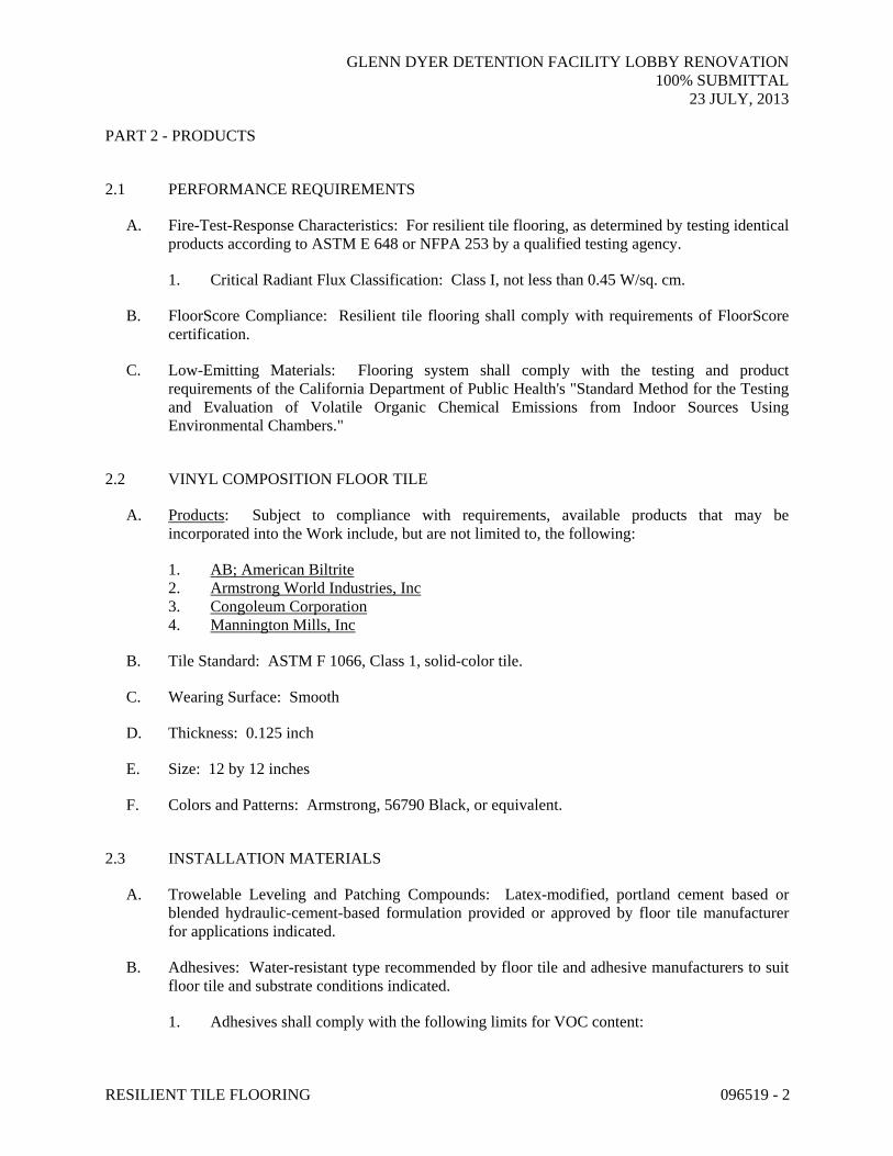
2.1 PERFORMANCE REQUIREMENTS
A. Fire-Test-Response Characteristics: For resilient tile flooring, as determined by testing identical products according to ASTM E 648 or NFPA 253 by a qualified testing agency.
1. Critical Radiant Flux Classification: Class I, not less than 0.45 W/sq. cm.
B. FloorScore Compliance: Resilient tile flooring shall comply with requirements of FloorScore certification.
C. Low-Emitting Materials: Flooring system shall comply with the testing and product requirements of the California Department of Public Health's "Standard Method for the Testing and Evaluation of Volatile Organic Chemical Emissions from Indoor Sources Using Environmental Chambers."
2.2 VINYL COMPOSITION FLOOR TILE
A. Products: Subject to compliance with requirements, available products that may be incorporated into the Work include, but are not limited to, the following:
1. AB; American Biltrite 2. Armstrong World Industries, Inc 3. Congoleum Corporation 4. Mannington Mills, Inc
B. Tile Standard: ASTM F 1066, Class 1, solid-color tile.
C. Wearing Surface: Smooth
D. Thickness: 0.125 inch
E. Size: 12 by 12 inches
F. Colors and Patterns: Armstrong, 56790 Black, or equivalent.
2.3 INSTALLATION MATERIALS
A. Trowelable Leveling and Patching Compounds: Latex-modified, portland cement based or blended hydraulic-cement-based formulation provided or approved by floor tile manufacturer for applications indicated.
B. Adhesives: Water-resistant type recommended by floor tile and adhesive manufacturers to suit floor tile and substrate conditions indicated.
1. Adhesives shall comply with the following limits for VOC content:

GLENN DYER DETENTION FACILITY LOBBY RENOVATION 100% SUBMITTAL
23 JULY, 2013
RESILIENT TILE FLOORING 096519 - 3
a. Vinyl Composition Tile Adhesives: 50 g/L or less.
2. Adhesives shall comply with the testing and product requirements of the California Department of Public Health's "Standard Method for the Testing and Evaluation of Volatile Organic Chemical Emissions from Indoor Sources Using Environmental Chambers."
C. Floor Polish: Provide protective, liquid floor-polish products recommended by floor tile manufacturer.
PART 3 - EXECUTION
3.1 PREPARATION
A. Prepare substrates according to floor tile manufacturer's written instructions to ensure adhesion of resilient products.
B. Concrete Substrates: Prepare according to ASTM F 710.
1. Verify that substrates are dry and free of curing compounds, sealers, and hardeners. 2. Remove substrate coatings and other substances that are incompatible with adhesives and
that contain soap, wax, oil, or silicone, using mechanical methods recommended by floor tile manufacturer. Do not use solvents.
3. Alkalinity and Adhesion Testing: Perform tests recommended by floor tile manufacturer. Proceed with installation only after substrate alkalinity falls within range on pH scale recommended by manufacturer in writing, but not less than 5 or more than 9 pH.
4. Moisture Testing: Proceed with installation only after substrates pass testing according to floor tile manufacturer's written recommendations, but not less stringent than the following:
a. Perform anhydrous calcium chloride test according to ASTM F 1869. Proceed with installation only after substrates have maximum moisture-vapor-emission rate of 3 lb of water/1000 sq. ft. in 24 hours.
b. Perform relative humidity test using in situ probes according to ASTM F 2170. Proceed with installation only after substrates have a maximum 75 percent relative humidity level.
C. Access Flooring Panels: Remove protective film of oil or other coating using method recommended by access flooring manufacturer.
D. Fill cracks, holes, and depressions in substrates with trowelable leveling and patching compound; remove bumps and ridges to produce a uniform and smooth substrate.
E. Do not install floor tiles until they are the same temperature as the space where they are to be installed.
F. Immediately before installation, sweep and vacuum clean substrates to be covered by resilient floor tile.

GLENN DYER DETENTION FACILITY LOBBY RENOVATION 100% SUBMITTAL
23 JULY, 2013
RESILIENT TILE FLOORING 096519 - 4
3.2 FLOOR TILE INSTALLATION
A. Comply with manufacturer's written instructions for installing floor tile.
B. Lay out floor tiles from center marks established with principal walls, discounting minor offsets, so tiles at opposite edges of room are of equal width. Adjust as necessary to avoid using cut widths that equal less than one-half tile at perimeter.
1. Lay tiles in pattern indicated on drawings.
C. Match floor tiles for color and pattern by selecting tiles from cartons in the same sequence as manufactured and packaged, if so numbered. Discard broken, cracked, chipped, or deformed tiles.
1. Lay tiles with grain running in one direction.
D. Scribe, cut, and fit floor tiles to butt neatly and tightly to vertical surfaces and permanent fixtures including built-in furniture, cabinets, pipes, outlets, and door frames.
E. Extend floor tiles into toe spaces, door reveals, closets, and similar openings. Extend floor tiles to center of door openings.
F. Maintain reference markers, holes, and openings that are in place or marked for future cutting by repeating on floor tiles as marked on substrates. Use chalk or other nonpermanent marking device.
G. Install floor tiles on covers for telephone and electrical ducts, building expansion-joint covers, and similar items in finished floor areas. Maintain overall continuity of color and pattern between pieces of tile installed on covers and adjoining tiles. Tightly adhere tile edges to substrates that abut covers and to cover perimeters.
H. Adhere floor tiles to flooring substrates using a full spread of adhesive applied to substrate to produce a completed installation without open cracks, voids, raising and puckering at joints, telegraphing of adhesive spreader marks, and other surface imperfections.
3.3 CLEANING AND PROTECTION
A. Comply with manufacturer's written instructions for cleaning and protecting floor tile.
B. Floor Polish: Remove soil, adhesive, and blemishes from floor tile surfaces before applying liquid floor polish.
1. Apply two coat(s).
C. Cover floor tile until Substantial Completion.
END OF SECTION 096519

GLENN DYER DETENTION FACILITY LOBBY RENOVATION 100% SUBMITTAL
23 JULY, 2013
TILE CARPETING 096813 - 1
SECTION 096813 - TILE CARPETING
PART 1 - GENERAL
1.1 SUMMARY
A. Section includes modular carpet tile.
1.2 PREINSTALLATION MEETINGS
A. Preinstallation Conference: Conduct conference at Project site.
1.3 ACTION SUBMITTALS
A. Product Data: For each type of product indicated.
B. LEED Submittals:
1. Product Data for Credit EQ 4.3:
a. For carpet tile, documentation indicating compliance with testing and product requirements of CRI's "Green Label Plus" program.
b. For installation adhesive, documentation including printed statement of VOC content of 50 g/L or less, as per SCAQMD Rule # 1168.
2. Laboratory Test Reports for Credit EQ 4: For carpet and installation adhesives, documentation indicating that products comply with the testing and product requirements of the California Department of Health Services' "Standard Practice for the Testing of Volatile Organic Emissions from Various Sources Using Small-Scale Environmental Chambers."
C. Samples: For each exposed product and for each color and texture specified, size to be 24” x 24”, 2 samples for each color / texture specified.
D. NSF / ANSI-140 Submittals: 1. Submit proof of independent third-party NSF / ANSI-140 Platinum Certification.
E. Submit written certification of specified recycled content percentages for all carpet products.
F. Submit documentation of manufacturer’s take-back program for carpet. Include: 1. Confirmation that the new carpet being installed will be acceptable (at the point of future
replacement) through a manufacturer’s operated program for recycling or reuse. 2. Written description of such a process for the recycling and / or recovery of used / worn
products. 3. Contact information for the take-back program.

GLENN DYER DETENTION FACILITY LOBBY RENOVATION 100% SUBMITTAL
23 JULY, 2013
TILE CARPETING 096813 - 2
G. Submit documentation of manufacturer’s / vendor’s recycling program for existing carpet. Include appropriate contact information, overview of procedures, and limitations and conditions applicable to the project.
1.4 INFORMATIONAL SUBMITTALS
A. Product test reports.
B. Sample warranty.
1.5 CLOSEOUT SUBMITTALS
A. Maintenance data.
1.6 MAINTENANCE MATERIAL SUBMITTAL
A. Furnish extra materials from the same production that match products installed and that are packaged with protective covering for storage and identified with labels describing contents. 1. Carpet tile: 10% of each material and color applied.
1.7 QUALITY ASSURANCE
A. Installer Qualifications: An experienced installer who is certified by the International Certified Floorcovering Installers Association at the Commercial II certification level.
B. Fire-Test-Response Ratings: Where indicated, provide carpet tile identical to those of assemblies tested for fire response according to NFPA 253 by a qualified testing agency.
1.8 DELIVERY, STORAGE, AND HANDLING
A. Comply with CRI 104.
1.9 FIELD CONDITIONS
A. Comply with CRI 104 for temperature, humidity, and ventilation limitations.
1.10 WARRANTY
A. Special Warranty for Carpet Tiles: Manufacturer agrees to repair or replace components of carpet tile installation that fail in materials or workmanship within specified warranty period.
1. Warranty does not include deterioration or failure of carpet tile due to unusual traffic, failure of substrate, vandalism, or abuse.

GLENN DYER DETENTION FACILITY LOBBY RENOVATION 100% SUBMITTAL
23 JULY, 2013
TILE CARPETING 096813 - 3
2. Failures include, but are not limited to, more than 10 percent edge raveling, snags, runs, dimensional stability, excess static discharge, loss of tuft bind strength, loss of face fiber, and delamination.
3. Warranty Period: 10 years from date of Substantial Completion.
PART 2 - PRODUCTS
2.1 CARPET TILE
A. NSF / ANSI-140 Platinum: All carpet products installed shall be certified to meet the NSF / ANSI-140 Platinum.
B. Products: Subject to compliance with requirements, available products that may be incorporated into the Work include, but are not limited to, the following:
1. Tandus Flooring
2. Shaw
C. Basis-of-Design Product: Subject to compliance with requirements, provide product indicated on Drawings or comparable product by one of the following:
1. Tandus Flooring
2. Shaw
D. Color: Tandus flooring Style: Street Life; Color: High Line 36106, or equivalent
E. Pattern: See color.
F. Fiber Content: 100% commercial grade nylon type 6 or type 6,6
G. Fiber Recycled Content: minimum 10% post-consumer recycled content.
H. Fiber Type: Nylon Fiber
I. Pile Characteristic: Patterned loop.
J. Tuft Density: 128 tufts / sq inch
K. Pile Height: 0.187 inch
L. Pile Thickness: 0.057” for finished carpet tile[ according to ASTM D 6859].
M. Stitches: 10.0 pile units per inch
N. Gage: 5/64

GLENN DYER DETENTION FACILITY LOBBY RENOVATION 100% SUBMITTAL
23 JULY, 2013
TILE CARPETING 096813 - 4
O. Primary Backing/Backcoating: Select one of the following two options: 1. PVC containing backing: Minimum 40% recycled content 2. Non-PVC material: no minimum recycled content
P. Secondary Backing / cushion: Must meet the current U.S. EPA Comprehensive Procurement Guidelines for Carpet Cushion: 1. Bonded polyurethane: 15 – 50% postconsumer content 2. Jute: 40% postconsumer content 3. Synthetic fibers: 100% total recovered materials content 4. Rubber: 60 – 90% postconsumer content
Q. Color System: 100% solution dye.
R. Size: 24 by 24 inches
S. Applied Soil-Resistance Treatment: Manufacturer's standard material.
T. Antimicrobial Treatment: Manufacturer's standard material.
U. Performance Characteristics: As follows:
1. Appearance Retention Rating: Moderate traffic, 2.5 minimum according to ASTM D 7330.
2. Critical Radiant Flux Classification: Not less than 0.45 W/sq. cm. 3. Dry Breaking Strength: Not less than 100 lbf according to ASTM D 2646. 4. Tuft Bind: Not less than 3 lbf according to ASTM D 1335. 5. Delamination: no delamination according to ASTM D 3936. 6. Dimensional Tolerance: Within 1/32 inch of specified size dimensions, as determined by
physical measurement. 7. Dimensional Stability: 0.2 percent or less according to ISO 2551 (Aachen Test). 8. Resistance to Insects: Comply with AATCC 24. 9. Colorfastness to Crocking: Not less than 4, wet and dry, according to AATCC 165. 10. Colorfastness to Light: Not less than 4 after 40 AFU (AATCC fading units) according to
AATCC 16, Option E. 11. Antimicrobial Activity: Not less than 2-mm halo of inhibition for gram-positive bacteria,
not less than 1-mm halo of inhibition for gram-negative bacteria, and no fungal growth, according to AATCC 174.
12. Electrostatic Propensity: Less than 3.5kV according to AATCC 134. 13. Emissions: Provide carpet tile that complies with testing and product requirements of
CRI's "Green Label Plus" program. 14. Emissions: Provide carpet tile that complies with the product requirements of the
California Department of Health Services' "Standard Practice for the Testing of Volatile Organic Emissions from Various Sources Using Small-Scale Environmental Chambers."
2.2 INSTALLATION ACCESSORIES
A. Trowelable Leveling and Patching Compounds: Latex-modified, hydraulic-cement-based formulation provided or recommended by carpet tile manufacturer.

GLENN DYER DETENTION FACILITY LOBBY RENOVATION 100% SUBMITTAL
23 JULY, 2013
TILE CARPETING 096813 - 5
B. Adhesives: Water-resistant, mildew-resistant, nonstaining, pressure-sensitive type to suit products and subfloor conditions indicated, that complies with flammability requirements for installed carpet tile and is recommended by carpet tile manufacturer for releasable installation.
1. Adhesives shall have a VOC content of 50 g/L or less when calculated according to 40 CFR 59, Subpart D (EPA Method 24).
2. Adhesives shall comply with the testing and product requirements of the California Department of Health Services' "Standard Practice for the Testing of Volatile Organic Emissions from Various Sources Using Small-Scale Environmental Chambers."
PART 3 - EXECUTION
3.1 EXECUTION
A. Removal and Recycling of Existing Carpet: Remove existing carpet for recycling in accordance with manufacturer recommendations and as follows: 1. Broadloom:
a. Remove used carpet in large pieces, roll tightly, and pack neatly in container. Include carpet scrap and waste from new installation. Immediately remove used carpet from site.
b. Deposit only clean, dry used carpets in containers. Clean shall be defined as carpet free from demolition debris or asbestos contamination, garbage, and tack strips.
2. Tile: a. Remove used carpet tile and stack neatly on pallets. Neatly stack carpet tiles or
repack in cardboard boxes prior to placing in container. Do not stack higher than 6 feet on pallets. Include carpet scrap and waste from new installation. Immediately remove used carpet from site.
b. Deposit only clean, dry used carpets in containers. Clean shall be defined as carpet free from demolition debris or asbestos contamination, garbage, and tack strips.
3. Remove adhesive according to recommendations of Carpet and Rug Institute (CRI). a. Adhesive removal solvents: Comply with Carpet and Rug Institute Publication
104. 4. Use a carpet recycling agency for all used carpet waste. Carpet scraps from the carpet
installation must also be recycled. 5. Notify project manager in writing which carpet recycling agency is used. 6. Comply with all applicable hauling and disposal regulations. 7. Carpet recycling agency must provide documentation after removal of the existing carpet
indicating the following: a. Date(s) material accepted at facility b. Total material accepted by facility c. Percentage of said carpet accepted for recycling
8. If there are no markets available to recycle existing carpet products and / or carpet is severely contaminated, vendor shall provide documentation to project manager as to why such products cannot be recycled. a. Old carpet contaminated with any controlled hazardous substances must be abated
by a properly qualified hazardous waste management company.

GLENN DYER DETENTION FACILITY LOBBY RENOVATION 100% SUBMITTAL
23 JULY, 2013
TILE CARPETING 096813 - 6
9. If carpet is destined to be recycled or refurbished by the manufacturer (i.e. if a take-back program was decided upon purchase of existing carpet), the manufacturer’s handling guidelines shall be followed.
3.2 INSTALLATION
A. Ensure that installation scraps are recovered at the time of the carpet installation; these scraps must be collected and entered into a recycling or reuse program complying with all governing, hauling, and disposal regulations of the authorities having jurisdiction.
B. Examine substrates, areas, and conditions, with Installer present, for compliance with requirements for maximum moisture content, alkalinity range, installation tolerances, and other conditions affecting carpet tile performance. Examine carpet tile for type, color, pattern, and potential defects.
C. Concrete Subfloors: Verify that concrete slabs comply with ASTM F 710.
D. Proceed with installation only after unsatisfactory conditions have been corrected.
E. Preparation: Comply with CRI 104, Section 6.2, "Site Conditions; Floor Preparation," and with carpet tile manufacturer's written installation instructions for preparing substrates indicated to receive carpet tile installation.
F. Installation: Comply with CRI 104, Section 14, "Carpet Modules," and with carpet tile manufacturer's written installation instructions.
G. Installation Method: As recommended in writing by carpet tile manufacturer
H. Maintain dye lot integrity. Do not mix dye lots in same area.
I. Cut and fit carpet tile to butt tightly to vertical surfaces, permanent fixtures, and built-in furniture including cabinets, pipes, outlets, edgings, thresholds, and nosings. Bind or seal cut edges as recommended by carpet tile manufacturer.
J. Extend carpet tile into toe spaces, door reveals, closets, open-bottomed obstructions, removable flanges, alcoves, and similar openings.
K. Maintain reference markers, holes, and openings that are in place or marked for future cutting by repeating on finish flooring as marked on subfloor. Use nonpermanent, nonstaining marking device.
L. Install pattern parallel to walls and borders, lay tiles with pattern direction alternating 90 degree turn in adjacent tiles.
M. Perform the following operations immediately after installing carpet tile:
1. Remove excess adhesive, seam sealer, and other surface blemishes using cleaner recommended by carpet tile manufacturer.
2. Remove yarns that protrude from carpet tile surface.

GLENN DYER DETENTION FACILITY LOBBY RENOVATION 100% SUBMITTAL
23 JULY, 2013
INTERIOR PAINTING 099123 - 1
SECTION 099123 - INTERIOR PAINTING
PART 1 - GENERAL
1.1 SUMMARY
A. Section includes surface preparation and the application of paint systems on following interior substrates:
1. Concrete. 2. Gypsum board.
1.2 DEFINITIONS
A. Gloss Level 1: Not more than 5 units at 60 degrees and 10 units at 85 degrees, according to ASTM D 523.
B. Gloss Level 2: Not more than 10 units at 60 degrees and 10 to 35 units at 85 degrees, according to ASTM D 523.
C. Gloss Level 3: 10 to 25 units at 60 degrees and 10 to 35 units at 85 degrees, according to ASTM D 523.
D. Gloss Level 4: 20 to 35 units at 60 degrees and not less than 35 units at 85 degrees, according to ASTM D 523.
E. Gloss Level 5: 35 to 70 units at 60 degrees, according to ASTM D 523.
F. Gloss Level 6: 70 to 85 units at 60 degrees, according to ASTM D 523.
G. Gloss Level 7: More than 85 units at 60 degrees, according to ASTM D 523.
1.3 ACTION SUBMITTALS
A. Product Data: For each type of product. Include preparation requirements and application instructions.
B. LEED Submittals:
1. Product Data for Credit EQ 4.2: For paints and coatings, including printed statement of VOC content.
2. Laboratory Test Reports for Credit EQ 4: For paints and coatings, documentation indicating that they meet the testing and product requirements of the California Department of Health Services' "Standard Practice for the Testing of Volatile Organic Emissions from Various Sources Using Small-Scale Environmental Chambers."

GLENN DYER DETENTION FACILITY LOBBY RENOVATION 100% SUBMITTAL
23 JULY, 2013
INTERIOR PAINTING 099123 - 2
C. Samples: For each type of paint system and in each color and gloss of topcoat.
D. Product List: For each product indicated. Include printout of current "MPI Approved Products List" for each product category specified in Part 2, with the proposed product highlighted.
1.4 MAINTENANCE MATERIAL SUBMITTALS
A. Furnish extra materials, from the same product run, that match products installed and that are packaged with protective covering for storage and identified with labels describing contents.
1. Paint: 10 percent, but not less than 1 gal. of each material and color applied.
1.5 QUALITY ASSURANCE
A. Mockups: Apply mockups of each paint system indicated and each color and finish selected to verify preliminary selections made under Sample submittals and to demonstrate aesthetic effects and set quality standards for materials and execution.
1. Architect will select one surface to represent surfaces and conditions for application of each paint system specified in Part 3.
2. Final approval of color selections will be based on mockups.
a. If preliminary color selections are not approved, apply additional mockups of additional colors selected by Architect at no added cost to Owner.
PART 2 - PRODUCTS
2.1 MANUFACTURERS
A. Products: Subject to compliance with requirements, available products that may be incorporated into the Work include, but are not limited to products listed in other Part 2 articles for the paint category indicated.
2.2 PAINT, GENERAL
A. MPI Standards: Provide products that comply with MPI standards indicated and that are listed in its "MPI Approved Products List."
B. Material Compatibility:
1. Provide materials for use within each paint system that are compatible with one another and substrates indicated, under conditions of service and application as demonstrated by manufacturer, based on testing and field experience.
2. For each coat in a paint system, provide products recommended in writing by manufacturers of topcoat for use in paint system and on substrate indicated.
GLENN DYER DETENTION FACILITY LOBBY RENOVATION 100% SUBMITTAL
23 JULY, 2013
INTERIOR PAINTING 099123 - 3
C. VOC Content: Zero VOC
D. Colors: As indicated on the drawings.
2.3 PRIMERS/SEALERS
A. Primer Sealer, Interior, Institutional Low Odor/VOC: MPI #149.
2.4 WATER-BASED PAINTS
A. Latex, Interior, Institutional Low Odor/VOC, Flat (Gloss Level 1): MPI #143.
PART 3 - EXECUTION
3.1 EXAMINATION
A. Examine substrates and conditions, with Applicator present, for compliance with requirements for maximum moisture content and other conditions affecting performance of the Work.
B. Maximum Moisture Content of Substrates: When measured with an electronic moisture meter as follows:
1. Concrete: 12 percent. 2. Gypsum Board: 12 percent.
C. Verify suitability of substrates, including surface conditions and compatibility with existing finishes and primers.
D. Proceed with coating application only after unsatisfactory conditions have been corrected.
1. Application of coating indicates acceptance of surfaces and conditions.
3.2 PREPARATION
A. Comply with manufacturer's written instructions and recommendations in "MPI Manual" applicable to substrates indicated.
B. Remove hardware, covers, plates, and similar items already in place that are removable and are not to be painted. If removal is impractical or impossible because of size or weight of item, provide surface-applied protection before surface preparation and painting.
1. After completing painting operations, use workers skilled in the trades involved to reinstall items that were removed. Remove surface-applied protection if any.
C. Clean substrates of substances that could impair bond of paints, including dust, dirt, oil, grease, and incompatible paints and encapsulants.

GLENN DYER DETENTION FACILITY LOBBY RENOVATION 100% SUBMITTAL
23 JULY, 2013
INTERIOR PAINTING 099123 - 4
1. Remove incompatible primers and reprime substrate with compatible primers or apply tie coat as required to produce paint systems indicated.
3.3 APPLICATION
A. Apply paints according to manufacturer's written instructions and to recommendations in "MPI Manual."
B. Apply paints to produce surface films without cloudiness, spotting, holidays, laps, brush marks, roller tracking, runs, sags, ropiness, or other surface imperfections. Cut in sharp lines and color breaks.
3.4 CLEANING AND PROTECTION
A. Protect work of other trades against damage from paint application. Correct damage to work of other trades by cleaning, repairing, replacing, and refinishing, as approved by Architect, and leave in an undamaged condition.
B. At completion of construction activities of other trades, touch up and restore damaged or defaced painted surfaces.
3.5 INTERIOR PAINTING SCHEDULE
A. Concrete Substrates, Nontraffic Surfaces:
1. Institutional Low-Odor/VOC Latex System:
a. Prime Coat: Primer sealer, interior, institutional low odor/VOC, MPI #149. b. Intermediate Coat: Latex, interior, institutional low odor/VOC, matching topcoat. c. Topcoat: Latex, interior, institutional low odor/VOC, flat (Gloss
Level 1), MPI #143.
B. Gypsum Board Substrates:
1. Institutional Low-Odor/VOC Latex System:
a. Prime Coat: Primer sealer, interior, institutional low odor/VOC, MPI #149. b. Intermediate Coat: Latex, interior, institutional low odor/VOC, matching topcoat. c. Topcoat: Latex, interior, institutional low odor/VOC, flat (Gloss
Level 1), MPI #143.
END OF SECTION 099123

GLENN DYER DETENTION FACILITY LOBBY RENOVATION 100% SUBMITTAL
23 JULY, 2013
TILE CARPETING 096813 - 7
3. Vacuum carpet tile using commercial machine with face-beater element.
N. Protect installed carpet tile to comply with CRI 104, Section 16, "Protecting Indoor Installations."
END OF SECTION 096813


GLENN DYER DETENTION FACILITY LOBBY RENOVATION 100% SUBMITTAL
23 JULY, 2013
09770 - 1 WALL PANEL SYSTEM APPLICATION
SECTION 09770 – INTERIOR WALL PANEL SYSTEM APPLICATION PART 1 – GENERAL 1.01 SECTION INCLUDES A. Interior wall panel system application.
B. Trim and accessories for attaching wall panels, including fastenings, accessory features, connections to the building structure, and other items not mentioned specifically herein, and which are necessary to make a complete installation.
1.03 QUALITY ASSURANCE
A. Work Quality: All work of this Section to be manufactured and
constructed, assembled and installed by skilled craft persons in finish carpentry. All such work to be accurately fabricated, assembled, joined and expertly finished in accordance with measurements taken on the job-site.
B. Defective Work: All work, work not true to line, not in satisfactory
operating condition, improperly installed, damaged or marred will not be accepted. Remedy, remove or replace defective work as directed by the Architect.
C. Standards: All applicable Sections of the "Manual of Millwork" and
current supplements published by the Woodwork Institute for the construction types and grades hereinafter specified. All modifications to such standards shown on the Contract Drawings and approved Shop Drawings or specified shall govern.
D. Manufacturer: Provide wall panels produced by one manufacturer
whose published product literature clearly indicates compliance with specifications.
E. No bright edges from cutting.
1.04 SUBMITTALS A. Shop Drawings
GLENN DYER DETENTION FACILITY LOBBY RENOVATION 100% SUBMITTAL
23 JULY, 2013
09770 - 2 WALL PANEL SYSTEM APPLICATION
B. Submit four samples, 3 1/2”x 3 1/2”, of each color, and texture of specified products. In addition, submit two samples, 18” x 18”, of each color, and texture of specified products.
C. Submit the following Quality Assurance Submittals:
1. Test Reports: Submit certified test reports showing compliance with specified performance characteristics and physical properties.
2. Product certificates signed by manufacturer certifying materials comply with specified performance characteristics and criteria and physical requirements
1.05 DELIVERY, STORAGE AND HANDLING A. Deliver and store materials in the manufacturer’s original protective
packaging. Store materials in an enclosed shelter providing protection from damage and exposure to the elements.
1.06 COORDINATION
A. Do work of this Section in a fully coordinated and cooperative manner with work of other trades to provide complete and proper installation and to expedite the job without delays.
B. Secure field measurements before preparation of shop drawings and
fabrication where possible, for proper and adequate fabrication and installation of the work.
C. Priming and back-painting of all carpentry and millwork is specified in
Section 099123 – Interior Painting. Do not set items until priming and back-painting have been completed.
D. Coordinate work with bullet resistant materials. Contractor shall not
start installing finish materials until all bullet resistant construction (which includes windows, counters, deal tray, fiberglass, and doors) are finalized, inspected, and approved.
E. Where Interior wall panels are clad around outside corners of a room,
the drywall installer should avoid installing drywall corner beads, as this makes shimming the interior wall panels very difficult. (See Section 09260).
F. Protect all work against damage of any kind until final acceptance of
the building. Repair or replace damaged work to the satisfaction of the Architect without additional cost to the Owner.

GLENN DYER DETENTION FACILITY LOBBY RENOVATION 100% SUBMITTAL
23 JULY, 2013
09770 - 3 WALL PANEL SYSTEM APPLICATION
G. Provide adequate ventilation and acclimate panels per Woodwork Institute Manual of Millwork.
1.07 WARRANTY A. Wall panel to be warranted against delamination for (5 Years). The
factory authorized fabricator, product installer and material manufacturer must sign and date the Warranty documents and submit a copy to the Contractor for the warranty to be valid.
PART 2 – PRODUCTS 2.01 MANUFACTURERS
A. These specifications are based on Interior wall panels manufactured by Wall Panel Systems and the wall panel trim and connectors manufactured by Wall Panel Systems, 877-333-4977. (www.wallpanelsystems.net)
B. All panel products specified in this section shall be provided by a single
manufacturer.
C. The listed manufacturer shall not be construed as closing specifications to other prospective manufacturer’s, but rather as establishing a level of quality in wall panel systems. Other systems may be submitted for approval as provided for in the specification at least 5 working days prior to submission of bids. Companies desiring to submit a proposal shall submit all descriptive information of the system proposed including photographs and shop drawings of at least three projects similar in detail and scope.
2.02 MATERIALS A. Basis of design: Wall Panel Systems, Inc., Clean Room System
Colors and surface texture as specified by Architect. Panels are to be fabricated as per details.
B. Thickness: A thickness of 3/8” is approved for interior walls with
concealed fasteners, “Z” clip installations. C. Panel color/texture: to be selected by Architect from Manufacturer’s
standard color pallet, this may include metallics, wood grains, & solid colors.
1. Color 1 side.
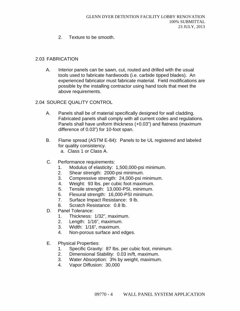
GLENN DYER DETENTION FACILITY LOBBY RENOVATION 100% SUBMITTAL
23 JULY, 2013
09770 - 4 WALL PANEL SYSTEM APPLICATION
2. Texture to be smooth. 2.03 FABRICATION
A. Interior panels can be sawn, cut, routed and drilled with the usual
tools used to fabricate hardwoods (i.e. carbide tipped blades). An experienced fabricator must fabricate material. Field modifications are possible by the installing contractor using hand tools that meet the above requirements.
2.04 SOURCE QUALITY CONTROL
A. Panels shall be of material specifically designed for wall cladding. Fabricated panels shall comply with all current codes and regulations. Panels shall have uniform thickness (+0.03”) and flatness (maximum difference of 0.03”) for 10-foot span.
B. Flame spread (ASTM E-84): Panels to be UL registered and labeled
for quality consistency. a. Class 1 or Class A.
C. Performance requirements: 1. Modulus of elasticity: 1,500,000-psi minimum. 2. Shear strength: 2000-psi minimum. 3. Compressive strength: 24,000-psi minimum.
4. Weight: 93 lbs. per cubic foot maximum. 5. Tensile strength: 13,000-PSI, minimum.
6. Flexural strength: 16,000-PSI minimum. 7. Surface Impact Resistance: 9 lb. 8. Scratch Resistance: 0.8 lb. D. Panel Tolerance: 1. Thickness: 1/32”, maximum.
2. Length: 1/16”, maximum. 3. Width: 1/16”, maximum. 4. Non-porous surface and edges.
E. Physical Properties: 1. Specific Gravity: 87 lbs. per cubic foot, minimum. 2. Dimensional Stability: 0.03 in/ft, maximum. 3. Water Absorption: 3% by weight, maximum. 4. Vapor Diffusion: 30,000

GLENN DYER DETENTION FACILITY LOBBY RENOVATION 100% SUBMITTAL
23 JULY, 2013
09770 - 5 WALL PANEL SYSTEM APPLICATION
F. Optical Properties: 1. Color Stability: Gray scale 4 – 5 according to ISO 105A02-87,
(3000 hours Xenon test 1200). 2. SO (2) resistance: Gray scale 4 – 5 (50 cycles 0.0067%).
2.05 SUB-FRAME ASSEMBLY
A. Aluminum “Z” clips and trim to be manufactured specifically to meet the following requirements:
1. Handle the weight of Interior wall panels. 2. Fasteners for panel assembly to be designed to keep panels
consistantly flat at each joint. 3. Capable of holding panels up to 6’ high x 12’ wide. 4. Allow 1/4" ventilation gap between the wall and the back side of
the panel clip, to prevent condensation behind the panels. 5. System to allow interchanging of components at a later date, with
a dry-fit installation. No liquid adhesives to be used.
B. Trim and Clip Material 1. Where not seen: Al 6061-T6, or equivalent. 2. Where visible: Al 6063-T5, or equivalent. 3. Thickness: not less than 0.62”.
C. Fasteners to be self-tapping Type F, 8/32” x 3/8” plated steel. D. Panel trim for joints, edges and corners to be from Wall Panel Systems;
Clean Room System, as shown on the drawings. 1. Finish:
a. Black Anodized
PART 3 – EXECUTION 3.01 INSTALLATION
A. Install panels and fixing system as per shop drawings and specification.
B. Install aluminum sub-frame to support the “Z” clip sub-frame
assembly.
GLENN DYER DETENTION FACILITY LOBBY RENOVATION 100% SUBMITTAL
23 JULY, 2013
09770 - 6 WALL PANEL SYSTEM APPLICATION
C. Maximum fixing distances: a. 2 fixing points in one direction using:
i. 8 mm panel is 27”. ii. 10 mm panel is 33”.
b. 3 or more fixing points in one direction: i. 8 mm panel is 31” ii. 10mm panel is 37”.
D. The installation of the panel clip system shall be true and plumb. E. Face of the panels are to sit out from the face of the wall ¾” +/-
1/16”shimming as required.
F. Installed panels shall have vertical joints with splines routed directly in the center of the panel edge to ensure that all four intersecting panels are kept in the same plane.
G. Exact sizes and dimensions of the trim to be coordinated with the
drawings, field conditions and approved shop drawings.
3.02 PROTECTION
A. After installation, the General Contractor shall protect the panels from damage. The panels shall be kept free from paint, plaster, cement scratches, or any other destructive forces.
3.03 CLEANING
A. Panels to be cleaned with standard cleaning solution. Mild solvents
may be used to remove stubborn marks and dirt.
B. Repair or replace all damaged material to the satisfaction of the Architect and/or Contractor.
C. Installed areas or portions of the work shall be inspected by Architect
or General Contractor and approved immediately following completion of such areas.
END OF SECTION

GLENN DYER DETENTION FACILITY LOBBY RENOVATION 100% SUBMITTAL
23 JULY, 2013
PANEL SIGNAGE 101423 - 1
SECTION 101423 - PANEL SIGNAGE
PART 1 - GENERAL
1.1 SUMMARY
A. Section Includes:
1. Panel signs.
1.2 ACTION SUBMITTALS
A. Product Data: For each type of product.
B. LEED Submittals:
1. Product Data for Credit IEQ 4.1: For adhesives, documentation including printed statement of VOC content.
2. Laboratory Test Reports for Credit IEQ 4.1: For adhesives, documentation indicating that products comply with the testing and product requirements of the California Department of Health Services' "Standard Practice for the Testing of Volatile Organic Emissions from Various Sources Using Small-Scale Environmental Chambers."
C. Shop Drawings: For panel signs.
1. Include fabrication and installation details and attachments to other work. 2. Show sign mounting heights, locations of supplementary supports to be provided by
others, and accessories. 3. Show message list, typestyles, graphic elements, including raised characters and Braille,
and layout for each sign at least half size.
D. Samples: For each exposed product and for each color and texture specified.
E. Sign Schedule: Use same designations specified or indicated on Drawings or in a sign schedule.
1.3 INFORMATIONAL SUBMITTALS
A. Sample warranty.
1.4 CLOSEOUT SUBMITTALS
A. Maintenance data.

GLENN DYER DETENTION FACILITY LOBBY RENOVATION 100% SUBMITTAL
23 JULY, 2013
PANEL SIGNAGE 101423 - 2
1.5 WARRANTY
A. Special Warranty: Manufacturer agrees to repair or replace components of signs that fail in materials or workmanship within specified warranty period.
1. Warranty Period: Five years from date of Substantial Completion.
PART 2 - PRODUCTS
2.1 PERFORMANCE REQUIREMENTS
A. Accessibility Standard: Comply with applicable provisions in the U.S. Architectural & Transportation Barriers Compliance Board's ADA-ABA Accessibility Guidelines for Buildings and Facilities and ICC A117.1 for signs.
2.2 SIGNS
A. Manufacturers: Subject to compliance with requirementsavailable manufacturers offering products that may be incorporated into the Work include, but are not limited to, the following:
B. Basis-of-Design Product: Subject to compliance with requirements, provide product indicated or comparable product by one of the following:
1. Ace Sign Systems, Inc. 2. Advance Corporation; Braille-Tac Division. 3. Allen Industries, Inc. 4. Allen Markings International. 5. APCO Graphics, Inc. 6. ASE, Inc. 7. ASI Sign Systems, Inc. 8. Best Sign Systems Inc. 9. Bunting Graphics, Inc. 10. Clarke Systems. 11. Diskey Sign Company. 12. Fossil Industries, Inc. 13. InPro Corporation. 14. Mohawk Sign Systems. 15. Nelson-Harkins Industries. 16. Poblocki Sign Company, LLC. 17. Seton Identification Products. 18. Supersine Company (The); Division of Stamp-Rite, Inc. 19. Vista System. 20. Vomar Products, Inc.
C. Panel Sign: Sign with smooth, uniform surfaces; with message and characters having uniform faces, sharp corners, and precisely formed lines and profiles; and as follows:

GLENN DYER DETENTION FACILITY LOBBY RENOVATION 100% SUBMITTAL
23 JULY, 2013
PANEL SIGNAGE 101423 - 3
1. Basis-of-Design Product: Indicated on Drawings.
2. Sign-Panel Perimeter: Finish edges smooth.
a. Edge Condition: Square cut. b. Corner Condition in Elevation: Square.
3. Mounting: countersunk flathead through fasteners or adhesive. 4. Surface Finish and Applied Graphics:
a. Integral Acrylic Sheet Color: As indicated on drawings.
2.3 PANEL-SIGN MATERIALS
A. Acrylic Sheet: ASTM D 4802, Type UVF (UV filtering).
2.4 ACCESSORIES
A. Fasteners and Anchors: Manufacturer's standard as required for secure anchorage of signage, noncorrosive and compatible with each material joined, and complying with the following:
1. Use concealed fasteners and anchors unless indicated to be exposed.
2. Sign Mounting Fasteners:
a. Concealed Studs: Concealed (blind), threaded studs welded or brazed to back of sign material or screwed into back of sign assembly, unless otherwise indicated.
b. Through Fasteners: Exposed metal fasteners matching sign finish, with type of head indicated, installed in predrilled holes.
B. Adhesives: As recommended by sign manufacturer and with a VOC content of 50 g/L or less for adhesives used inside the weatherproofing system and applied on-site when calculated according to 40 CFR 59, Subpart D (EPA Method 24).
C. Adhesives: As recommended by sign manufacturer and that comply with the testing and product requirements of the California Department of Health Services' "Standard Practice for the Testing of Volatile Organic Emissions from Various Sources Using Small-Scale Environmental Chambers."
2.5 FABRICATION
A. General: Provide manufacturer's standard sign assemblies according to requirements indicated.
1. Mill joints to a tight, hairline fit. Form assemblies and joints exposed to weather to resist water penetration and retention.
2. Provide welds and brazes behind finished surfaces without distorting or discoloring exposed side. Clean exposed welded and brazed connections of flux, and dress exposed and contact surfaces.

GLENN DYER DETENTION FACILITY LOBBY RENOVATION 100% SUBMITTAL
23 JULY, 2013
PANEL SIGNAGE 101423 - 4
3. Conceal connections if possible; otherwise, locate connections where they are inconspicuous.
4. Internally brace signs for stability and for securing fasteners. 5. Provide rebates, lugs, and brackets necessary to assemble components and to attach to
existing work. Drill and tap for required fasteners. Use concealed fasteners where possible; use exposed fasteners that match sign finish.
PART 3 - EXECUTION
3.1 INSTALLATION
A. General: Install signs using mounting methods indicated and according to manufacturer's written instructions.
1. Install signs level, plumb, true to line, and at locations and heights indicated, with sign surfaces free of distortion and other defects in appearance.
2. Install signs so they do not protrude or obstruct according to the accessibility standard. 3. Before installation, verify that sign surfaces are clean and free of materials or debris that
would impair installation. 4. Corrosion Protection: Coat concealed surfaces of exterior aluminum in contact with
grout, concrete, masonry, wood, or dissimilar metals, with a heavy coat of bituminous paint.
B. Mounting Methods:
1. Concealed Studs: Using a template, drill holes in substrate aligning with studs on back of sign. Remove loose debris from hole and substrate surface.
a. Masonry Substrates: Fill holes with adhesive. Leave recess space in hole for displaced adhesive. Place sign in position and push until flush to surface, embedding studs in holes. Temporarily support sign in position until adhesive fully sets.
b. Thin or Hollow Surfaces: Place sign in position and flush to surface, install washers and nuts on studs projecting through opposite side of surface, and tighten.
2. Through Fasteners: Drill holes in substrate using predrilled holes in sign as template. Countersink holes in sign if required. Place sign in position and flush to surface. Install through fasteners and tighten.
3. Adhesive: Clean bond-breaking materials from substrate surface and remove loose debris. Apply linear beads or spots of adhesive symmetrically to back of sign and of suitable quantity to support weight of sign after cure without slippage. Keep adhesive away from edges to prevent adhesive extrusion as sign is applied and to prevent visibility of cured adhesive at sign edges. Place sign in position, and push to engage adhesive. Temporarily support sign in position until adhesive fully sets.
C. Remove temporary protective coverings and strippable films as signs are installed.
D. END OF SECTION 101423

GLENN DYER DETENTION FACILITY LOBBY RENOVATION 100% SUBMITTAL
23 JULY, 2013
SIMULATED STONE COUNTERTOPS 123661 - 1
SECTION 123661 - SIMULATED STONE COUNTERTOPS
PART 1 - GENERAL
1.1 SUMMARY
A. Section Includes: 1. Quartz agglomerate countertops.
1.2 ACTION SUBMITTALS
A. Product Data: For countertop materials.
B. LEED Submittals: 1. Product Data for Credit IEQ 4.4: For adhesives and composite wood products,
documentation indicating that product contains no urea formaldehyde. 2. Laboratory Test Reports for Credit IEQ 4: For adhesives, sealants and composite wood
and agrifiber products, documentation indicating that products comply with the testing and product requirements of the California Department of Health Services' "Standard Practice for the Testing of Volatile Organic Emissions from Various Sources Using Small-Scale Environmental Chambers."
C. Shop Drawings: For countertops. Show materials, finishes, edge and methods of joining.
D. Samples: For each type of material exposed to view.
PART 2 - PRODUCTS
2.1 QUARTZ AGGLOMERATE COUNTERTOPS
A. Configuration: as indicated on drawings
B. Countertops: 1-1/4” thick, quartz with front edge built up with same material.
2.2 COUNTERTOP MATERIALS
A. Composite Wood and Agrifiber Products: Provide products that comply with the testing and product requirements of the California Department of Health Services' "Standard Practice for the Testing of Volatile Organic Emissions from Various Sources Using Small-Scale Environmental Chambers," including 2004 Addenda.
B. Particleboard: ANSI A208.1, Grade M-2, made with binder containing no urea formaldehyde.

GLENN DYER DETENTION FACILITY LOBBY RENOVATION 100% SUBMITTAL
23 JULY, 2013
SIMULATED STONE COUNTERTOPS 123661 - 2
C. Plywood: Exterior softwood plywood complying with DOC PS 1, Grade C-C Plugged, touch sanded.
D. Adhesives: Adhesives shall comply with the testing and product requirements of the California Department of Health Services' "Standard Practice for the Testing of Volatile Organic Emissions from Various Sources Using Small-Scale Environmental Chambers."
E. Quartz: Solid sheets consisting of quartz aggregates bound together with a matrix of filled plastic resin and complying with the "Physical Characteristics of Materials" Article of ANSI SS1.
1. Manufacturers: Subject to compliance with requirements, manufacturers offering products that may be incorporated into the Work include, but are not limited to, the following:
a. Cambria. b. Cosentino USA. c. E. I. du Pont de Nemours and Company. d. LG Chemical, Ltd. e. Meganite Inc. f. Samsung Chemical USA, Inc. g. Technistone USA, Inc. h. Transolid, Inc.
2. Colors and Patterns: black.
PART 3 - EXECUTION
3.1 INSTALLATION
A. Fasten countertops by screwing through corner blocks of base units into underside of countertop. Align adjacent surfaces and, using adhesive in color to match countertop, form seams to comply with manufacturer's written instructions. Carefully dress joints smooth, remove surface scratches, and clean entire surface.
END OF SECTION 123661

GLENN DYER DETENTION FACILITY LOBBY RENOVATION 100% SUBMITTAL
23 JULY, 2013
SECTION 130700 – BULLET RESISTANT FIBERGLASS UL752 LEVEL IV (BGAA-04) Cross Reference: Section 082110 – Bullet Resistant Full Lite Aluminum Door & Frame Assembly
Section 085513 – Bullet Resistant 3 Sided Transaction Window
PART 1 GENERAL 1.1 REFERENCE The publications listed below form a part of this specification. NATIONAL INSTITUTE OF JUSTICE STANDARD 0108.01-STANDARD FOR BALLISTIC RESISTANT PROTECTIVE MATERIALS (September, 1985). UNDERWRITERS LABORATORY UL 752 9th Edition, Standard for Bullet Resisting Equipment (January 27, 1995). 1.2 SUBMITTALS Submit for approval prior to fabrication samples, brochures, specifications, UL Listing and UL752 Current Test Results as provided by Underwriters Laboratory, and printed data in sufficient detail to indicate compliance with the contract documents. Manufacturer’s instructions for installation of Bullet Resistant Fiberglass. 1.3 DESIGN Through the design, manufacturing technique and material application the Bullet Resistant Fiberglass shall be of the “non ricochet type”. This design is intended to permit the encapture and retention of an attacking projectile lessening the potential of a random injury or lateral penetration. 1.4 DELIVERY, STORAGE AND HANDLING Deliver the materials to the project with the UL Listed Labels and the manufacturer’s UL752 designation labels intact and legible. Handle the material with care to prevent damage. Store the materials inside under cover; stack flat and off the floor. 1.5 WARRANTY All materials and workmanship shall be warranted against defects for a period of 2 (two) years from the date of receipt at the project site.

GLENN DYER DETENTION FACILITY LOBBY RENOVATION 100% SUBMITTAL
23 JULY, 2013 PART 2 PRODUCTS 2.1 BULLET RESISTANT FIBERGLASS MATERIAL The panels shall be made of multiple layers of woven roving ballistic grade fiberglass cloth impregnated with the thermoset polyester resin and compressed into flat rigid sheets. The production technique and materials used shall provide the controlled internal delamination to permit the encapture of a penetrating projectile. Bullet Resistant Fiberglass panel: 1- 3/8” maximum thickness, and 14 pounds per square foot maximum weight. Material shall be Bullet Guard Architectural Armor (BGAA-04), by Bullet Guard Corporation, West Sacramento, CA, Phone (916) 373-0402, Fax (916) 373-0208, email: [email protected] , Website: www.bulletguard.com 2.2 SECURITY LEVEL The Bullet Resistant Fiberglass will be UL Listed and Tested for UL752 Level IV. 2.3 FIRE RATING (BGAA-04) Has a one-hour fire rating per ASTM E119-98 and can be used for fire corridors and firewalls. PART 3 EXECUTION 3.1 SUPPORTING MEMBERS Prior to installing the bullet resistive material the contractor shall verify that all supports have been installed as required by the contract documents and the architectural drawings. 3.2 JOINTS All joints shall be reinforced by a back-up layer of bullet resistive material. The bullet resistance of the joint, as reinforced, shall be at least equal to that of the panel. Minimum width of reinforcing layer at joint shall be 4-inches (2” on each panel or a 2” minimum overlap). 3.3 APPLICATION Armor shall be installed in accordance with the manufacturer’s printed recommendations. Armor panels shall be adhered using an industrial adhesive, mastic, screws or bolts. Method of application shall maintain the bullet resistive rating at junctures with the concrete floor slab, the concrete roof slab, the bullet resistive doorframes, the bullet resistive window frames, and all required penetrations. **End of Section**

GLENN DYER DETENTION FACILITY LOBBY RENOVATION 100% SUBMITTAL
23 JULY, 2013 1/5/98 13070-2


GLENN DYER DETENTION FACILITY LOBBY RENOVATION 100% SUBMITTAL
23 JULY, 2013
INTERIOR LIGHTING FIXTURES, LAMPS, AND BALLASTS 26 51 13 - 1
SECTION 56 51 13 – INTERIOR LIGHTING FIXTURES, LAMPS, AND BALLASTS
PRODUCT MINIMUM REQUIREMENTS
Equipment must meet the requirements listed below. Equipment must be installed in a manner that delivers the expected savings while maintaining the appropriate lighting levels.
Linear Fluorescent Electronic Ballasts
Standard output ballasts must have a ballast factor of 0..87 - 0..89. Reduced output ballasts must have a ballast factor of 0. 77 - 0.78 Catalog or reference output must have a ballast factor of 0.95 – 1.05. High output ballasts must have a ballast factor of 1.15-1.20. Linear fluorescent retrofit measures with T8 lamps must have “extra-efficient” ballasts from the following list of manufacturers and brand names:
Advance Optanium instant start
Linear Fluorescent Lamps 1. All new 2-foot fluorescent lamps used in fixtures shall be F17T8 (when required).
3. All new 4-foot fluorescent lamps used in fixtures shall be F32T8 (Preferred). Linear fluorescent lamps must be “premium” quality, meaning that they must have the following characteristics
A minimum rated life (at 3-hour start rating) of 24,000 hours with instant start ballasts. Lamps must have a CRI between 80 and 86. Lamps must have color temperature 5000K 4-foot Lamps must have an initial (catalog) lumen output > 3000 lumens. Lamps must carry a three-year parts warranty. Lamps shall be designated as “low mercury content,” with < 6 mg of mercury per 4-foot lamp.
4. Model numbers for the T-8 lamps shall be as follows: Material Product 2 foot T-8 Lamps (when required)
Philips F17T8/ADV850/ALTO
3 foot T-8 Lamps (by acceptation Philips F25T8/ADV850/ALTO

GLENN DYER DETENTION FACILITY LOBBY RENOVATION 100% SUBMITTAL
23 JULY, 2013
INTERIOR LIGHTING FIXTURES, LAMPS, AND BALLASTS 26 51 13 - 2
only) 4 foot T-8 Lamps (Preferred) Philips Advantage – F32T8/ADV850/ALTO
New Recessed Troffer Fixture
New 2’ X 4’ recessed troffer fixture should feature two lamps Direct/Indirect and be Lithonia model Avante (Model # 2AV-G-S-32-MDR-MVOLT-GEB101S.) Specify fixture with 5000K lamps (see above). One or three lamp fixtures are acceptable if needed, based on lighting levels required. The County’s acceptable desktop light level for workspaces is above 30 Foot-candles (maintained). All new fixtures need to include quick disconnects to meet current NEC codes.
High Bay Fluorescent Fixtures
New indoor high bay Fluorescent fixtures should be Precision Fluorescent model OHEE-PC-6-6L32-UL2-HP-PS-M4-C8 or equivalent New outdoor high bay Fluorescent fixtures should be Precision Fluorescent model GCR-6-6L32-UL2-HP-IS-M4-CA or equivalent
Lenses
Lenses shall be made from clear prismatic, acrylic material of 0.125" thickness (A12). Wrap-around lenses must be sized and contoured to be similar to factory-supplied lenses in appearance. Flat lenses must be cut evenly and sized properly so they can be installed in a secure manner.
Reflectors
Retrofit reflectors and reflector kits must be constructed of steel or aluminum and white powder coat finish with a total reflectivity 91%. Unacceptable Indoor Fixtures U-tube fixtures, two-pin compact fluorescent lamps, 3-foot fluorescent lamps, parabolic lenses, incandescent lamps, HID lamps, and 8’ fluorescent lamps are not acceptable in interior spaces at County facilities.