swedishcr.weebly.com · Web viewLogic gates & Flip Flops using PLC ladder logic implementation 15...
58
Industrial ELECTRONICS Lab EL-423 Prepared By :Engr Usama Bukhari Swedish College of Engineering and Technology, RYK Punjab, Pakistan INDUSTRIAL ELECTRONICS Laboratory Manual 8 th Semester Batch 2010-2014 Student Name: ________________________ Class Roll No: ________________________ Exams Roll No: ________________________
Transcript of swedishcr.weebly.com · Web viewLogic gates & Flip Flops using PLC ladder logic implementation 15...
Industrial ELECTRONICS LabEL-423Prepared By :Engr Usama Bukhari
Swedish College of Engineering and Technology, RYKPunjab, Pakistan
INDUSTRIAL ELECTRONICSLaboratory Manual
8th Semester Batch 2010-2014
Student Name: ________________________ Class Roll No: ________________________ Exams Roll No: ________________________
Verification of Instructed: ____________________
Grading: ____________________
Dated: ____________________

Sr. No. EXPERIMENTS Page No.
01 An overall look at Programmable Logic Controllers & its Applications 3
02 Getting familiar with Step 7- Micro/Win 32and the S7-200 PLC 8
03 Logic gates & Flip Flops using PLC ladder logic implementation 15
04 Stamp Machine using Bit Logic Instructions 20
05 Timers Function using PLC 26
06 Counters control Function using SIMATIC7’200 33
07Two Counters Used With A Common Register To Give The Sum Of Two
Count 39
08A Process Where A Timed Interval Is Started When A Count Reaches A
Preset Value 42
09 Sequencer control using PLC SIMATIC’7 45
10 Program Control Instructions using Micro wind XP224. 49
11 Data Manipulation Instructions 57
12 Math Instructions using Micro wind S’7 61
13 Traffic signal Control by PLC 70
14 Water Level Control By PLC 77
15 Elevator Control By PLC 83
16 Temperature Control By PLC 90
LAB CONTENTS

DEPARTMENT OF ELECTRONIC ENGINEERING, SCE&T, RAHIM’YAR’KHAN
INDUSTRIAL ELECTRONICS (8TH SEMESTER, FINAL YEAR) EXPERIMENT # 1/16
Name: ________________________________________Roll No: _____________________
Score: ______________Signature of the Lab Tutor: __________________Date: ____________
----------------------------------------------------------------------------------------------------------------------------
AN OVERALL LOOK AT PROGRAMMABLE LOGIC CONTROLLERS & its
APPLICATIONS
OBJECTIVE:
Upon the successful completion of the experiment, the students will be able to
Understand the programming procedures and its industrial values.
REFRENCE:
John W. Webb. Ronald A. Reis, ”Programmable Logic Controllers”.
DISCUSSION:
Early machines were controlled by mechanical means using cams, gears, levers, and other basic
mechanical devices. As the complexity grew, so did the need for a more sophisticated control
system. This system contained wired relay and switch control elements. These elements were
wired as required to provide the control logic necessary for the particular type of machine
operation, this was acceptable for a machine that never needed to be changed or modified, but as
manufacturing techniques improved and plant changeover to new products became more
desirable and necessary, a more versatile means of controlling this equipment had to be
developed . Hardwired relay and switch logic was cumbersome and time consuming to modify.
Wiring had to be removed and replaced to provide for the new control scheme. This modification
was difficult and time consuming to design and install and any “bug” in the design could be a
major problem to correct since it also required rewiring of the system . A new means to modify
control circuitry was needed. The development and testing ground for this new means was the
U.S. auto industry. The time period was the late 1960’s and early 1970’s and the result was the
programmable logic controllers, or PLC. Automotive plants were confronted with a change in
manufacturing techniques every time a model change and PLC has at first gradually , in some
cases, for changes on the same model if improvements had to be made during the model year.

The PLC provided an easy way of program the wiring rather than actually rewiring the control
system.
The PLC that was developed during this time was not easy to program. The language was
cumbersome to write, requiring highly trained programmers. These early devices were merely
relay replacements and could do very little else. The PLC has at first gradually,, and in recent
years rapidly, developed into a sophisticated and highly versatile control system components.
Units today are capable of performing complex math functions including numerical integration
and differentiation and operate at the fast microprocessor speeds now available.
Over ALL PLC system
The PLC system consist of four major units and they are interconnected.
1. Central Processing Unit(CPU).The “brain” of the system, which has three subparts
a. Microprocessor. The computer center that carries out mathematics and logic operations.
b. Memory. The area of CPU in which data and information is stored or retrieved .Holds the system
software and user program.
c. Power Supply: The electrical supply that converts alternating (AC) line voltage to various
operational DC values. In the process, the power supply filters and regulate the DC voltages to
ensure proper computer operation.
2. I/O Modules: the input has terminal into which outside process electrical signals, generated by
sensors or transducers, are entered. The output module has terminals to which output signals are sent
to activate relays, solenoids, various slid-state switching devices, motors, and display, an electronic
system for connecting I/O modules to remote locations can be added if needed. The an/actual
operating process under OPLC control can be thousand odd feet from the CPU and its I/O modules.
3. Programmer/Monitor: the programmer/monitor(PM) is a device used to communicate with the
circuits of the PLC. Hand Held terminals, industrial terminals, and the personal computer exist as PM
devices. In a hand held unit input takes through a membrane keypad and the display (LCD) . With the
industrial terminal or personal computer, more complex, typewriter type keyboards and cathode ray
tubes (CRTs) are employed.
4. Racks & Chassis: The racks on which the PLC parts are mounted & the enclouseres on
which the CPU, PM & I/O modules are mounted.
PLC Advantages:Following are the 13 major advantages of using a PLC.
Flexibility
Implementing changes & correcting errors
Large quantities of contacts
Lower cost
Pilot running
Visual observation
Speed of operation
Ladder or Boolean Programming methods
Reliability & maintainability
Simplicity of Control System components
Documentation
Security
Ease of changes by Reprogramming

Newer technology
Fixed program applications
Environmental considerations
Fail-safe operations
OBSERVATIONS:
________________________________________________________________________
________________________________________________________________________
________________________________________________________________________
________________________________________________________________________
________________________________________________________________________
________________________________________________________________________
________________________________________________________________________
_____________________

ES-423 Lab Grading Sheet
Lab 1Student Name:………………….. Roll No:…………..
Instructions Print this grading sheet, write your name and roll number at the top, and give it to the Instructor/lab Engineer during your lab check off. Include this as the cover page to your lab report.
Instructor/Lab engineer Grading Section Check Off During your in-lab check off, be prepared to show the Instructor/Lab Engineer the following:
• The connections of the circuit of the experiment • Real Time values of the observed data • Properly Running the Machine within safe limits • Table containing Measurements and Calculations • Graph between the observed quantities
Reminder: This lab requires a Full Report Worksheet Score:
Instructor/Lab Engineer’s Comments:
_______ (of 5) Organization & Quality
_______ (of 5) Completeness & Correctness of Figures
_______ (of 5) Discussion Topics / Q & A
Instructor/Lab Engineer
Date Instructor/Lab Engineer Score (0-5)
Instructor/Lab EngineerReport
Score (0-15)Total
Score (0-20)

DEPARTMENT OF ELECTRONIC ENGINEERING, SCE&T, RAHIM’YAR’KHAN
INDUSTRIAL ELECTRONICS (8TH SEMESTER, FINAL YEAR) EXPERIMENT # 2/16
Name: ________________________________________Roll No: _____________________
Score: ______________Signature of the Lab Tutor: __________________Date: ____________
----------------------------------------------------------------------------------------------------------------------------
GETTING FAMILIAR WITH STEP 7- MICRO/WIN 32AND THE
S7-200 PLC
OBJECTIVE
Upon successful completion of this lab the students will be able to
To construct PLC programs in LAD using Siemens Step 7-Micro/Win 32.
To run and debug the programs on S7-200 PLC.
REFERENCE
John.W.Webb.Ronald A.Reis,”programmable logic controllers”.
Introduction:
Controllers may consist of logical components and connections among them. Depending
on the current logical value of input, output is produced to change the status of the system. PLC
may realize such controllers. Today, the command and feedback control systems of industrial
automation systems are realized by programmable logic controllers (PLCs). Siemens Simatic S7-
200 is one of the PLC brands widely used in industry.
In order for PLCs to work as controllers, they mustbe able to realize some functions. These
functions are basic and combinational logic operations such as AND, OR, AND-NOT,
OR-NOT, timer and counter operations. In addition to these, PLCs may have the ability
to realize several transfer, mathematical, and PID operations.PLC consists of three main parts:
CPU, memory and I/O units. CPU is the brain of PLC. It reads the input values from inputs, runs
the program existed in the program memory and writes the output values to the output register.
Memory is used to store different types ofinformation in the binary structure form. The memory
range of S7-200 is composed of three main parts as program, parameter, and retentive data
fields. I/O units provide communication between PLC control systems.

Constructing of PLC Program
There are mainly two methods for composing PLC programs: Ladder Logic Diagram
(LAD) and Statement List(STL).
LAD method is commonly used to implement the programs for process controls. A network of
LAD is a row of connected elements that form a complete circuit between the left anright power
rail.
The left power rail represents the energized conductor whereas the right power rail represents the
return path conductor of the circuit.
Power flows from the left rail, through the closed contacts to the coils or boxes connected to the
right power rail.
You can then use the power flow to activate the outputs according to your program.
Step 7-Micro/Win 32 is user-friendly development environment for S7-200. A screen shot of
Step 7-Micro/Win 32 is shown in Figure 1.1.
Figure 1.1 Step 7-Micro/Win 32
A simple LAD realizing some Boolean operations is given below:
Figure 1.2 Sample LAD for Boolean operations.
You can also switch between LAD and STL by selecting Ladder or STL from View menu. By
this way, you can see how LAD and STL relate to each other.
Figure 1.3STL codes for the LAD in Figure 1.2

In STEP 7-Micro/WIN 32, click on New option in the Project menu for new project. After
composing program, click the Compile button on the taskbar. By clicking this button,
software translates the program code block into machine language for execution by the
CPU. A program can not be downloaded to the CPU until it is compiled. If there is an error in
your program, your program will not be compiled and software will warn you about the errors in
your program. After correcting errors, try to compile again.
You can save your work by clicking Save All option in the Project menu. You can also load
existed projects by clicking Open option in the Project menu
Running PLC Programs
When the program is compiled successfully, click on the Download button on the taskbar to
transfer the compiled program to the PLC. During this operation, be sure that PLC is STOP or
TERM mode. When the transfer is completed, switch the PLC to RUN mode or click
RUN button in the toolbar .Now, PLC is running. Switch the inputs ON and OFF, and observe
the change on outputs of the PLC module. Check if your program works correctly.You can also
transfer the existed program in PLC to PC. In a similar way, when the PLC is STOP mode,
click on the Upload button on the taskbar. When the operation is completed, you can see the
program code existed in PLC on computer screen. Now you can modify the program if it is
necessary.
You can change the mode of PLC to either RUN, STOP or TERM using the switch on
the PLC module.

Experimental Work
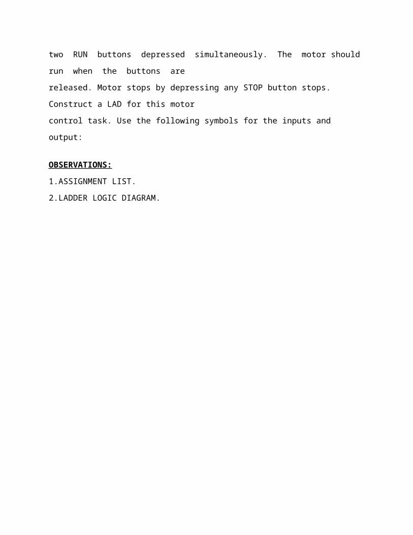
1. Construct a LAD for the following Boolean functions operations using the STEP
7-Micro/WIN
32. Transfer and run your programs on the PLC and verify that the PLC operates according to
the Boolean functions.
2. A PLC motor controller has two START buttons and two STOP buttons. The motor is to run
if
two RUN buttons depressed simultaneously. The motor should run when the buttons are
released. Motor stops by depressing any STOP button stops. Construct a LAD for this motor
control task. Use the following symbols for the inputs and output:
OBSERVATIONS:
1.ASSIGNMENT LIST.
2.LADDER LOGIC DIAGRAM.


ES-423 Lab Grading Sheet
Lab 2Student Name:………………….. Roll No:…………..
Instructions Print this grading sheet, write your name and roll number at the top, and give it to the Instructor/lab Engineer during your lab check off. Include this as the cover page to your lab report.
Instructor/Lab engineer Grading Section Check Off During your in-lab check off, be prepared to show the Instructor/Lab Engineer the following:
• The connections of the circuit of the experiment • Real Time values of the observed data • Properly Running the Machine within safe limits • Table containing Measurements and Calculations • Graph between the observed quantities
Reminder: This lab requires a Full Report Worksheet Score:
Instructor/Lab Engineer’s Comments:
_______ (of 5) Organization & Quality
_______ (of 5) Completeness & Correctness of Figures
_______ (of 5) Discussion Topics / Q & A
Instructor/Lab EngineerDEPARTMENT OF ELECTRONIC ENGINEERING, SCE&T, RAHIM’YAR’KHAN
INDUSTRIAL ELECTRONICS (8TH SEMESTER, FINAL YEAR) EXPERIMENT # 3/16
Date Instructor/Lab Engineer Score (0-5)
Instructor/Lab EngineerReport
Score (0-15)Total
Score (0-20)
Name: ________________________________________Roll No: _____________________
Score: ______________Signature of the Lab Tutor: __________________Date: ____________
----------------------------------------------------------------------------------------------------------------------------
LOGIC GATES & FLIP FLOPs
OBJECTIVE:
Upon the useful completion of this experiment, the students will be able to
Take advantages of the orders of program execution in a PLC to perform digital logic gates
functions.
Construct fundamental asynchronous and clocked flip flop in ladder logic.
Construct a J-K flip flop in plc ladder diagram.
REFERENCE: John W.Webb.Ronald A.Reis, “Programmable Logic Controllers.”
TOOLS:
S7-200 Micro PLC.
Personal Computer
Input modules
DISCUSSIONS:
This activity illustrates the use of a digital logic gates from a PLC logic stand point. All
gates have one output. The outputs either on or off depends on the logic status of their inputs. A
gate on condition is typical when +5 volts DC comes from the output terminal. Off is typically 0
volts output. An input on condition is typically when +5 volts DC is applied to an input terminal.
Off is typically 0 volts to an input terminal.
Ladder Diagram of AND Gate
.
Ladder Diagram of OR Gate
Ladder Diagram of NOT Gate
Ladder Diagram of NAND Gate
Ladder Diagram of NOR Gate
D FLIP FLOP.
DISCUSSION:
In a ladder D-flip flop has two inputs (D and clock). In operation, the state of D input is
transferred to the Q output of the flip flop at the time of clock pulse. The truth table for D flip
flop is shown.
D CL QN QN+1
0 0 X QN
0 1 X 0
1 0 Q QN

1 1 X 1
In the table column QN contains the state of flip flop Q output prior to the clock, and the column
labeled QN+1 contains the state of Q output of the flip flop after the application of the clock.
A ladder D flip flop shown is a one rung function I0.1 and I0.2 and one coil Q 0.1 in this case
I0.1 is the input and I0.2 is the clock.
J-K FLIP FLOPDISCUSSION:
The truth table for J-K Flip Flop is as under:-
J K CL Q n Q n+10 0 1 Q n Q n
0 1 1 X 0
1 0 1 X 1
1 1 1 Q n Q n
X X X Q n Q n
For this truth table, an X in any block indicates a “don’t care” condition, a 1 in the CL (clock)
column indicates the clock makes a 0 to 1 to 0 transition, and a 0 in the CL column indicates
“don’t care” condition, a 1 in the CL(clock) column indicates the clock makes a 0 to 1 transition,
and a 0 in the CL column indicates no clock transition. The Qn column contains the flip flop
state prior to the application of a clock, and the Qn+1 column contains the flip flop state after the
clock. The ladder diagram for a J-K flip flop in which 10.1=J, 10.2=K, 10.3=CL is shown in fig

Ladder Diagram of J-K Flip Flop
REVIEW QUESTIONS:
1.What do you mean by Toggling?
2.What will happen when clock pulse is not applied?
3.What do you mean by rung?
4.What will happen when the clock pulse is not applied?
5.What do you mean by Toggling?
6.What will happen when clock pulse is not applied?

ES-423 Lab Grading Sheet
Lab 3Student Name:………………….. Roll No:…………..
Instructions Print this grading sheet, write your name and roll number at the top, and give it to the Instructor/lab Engineer during your lab check off. Include this as the cover page to your lab report.
Instructor/Lab engineer Grading Section Check Off During your in-lab check off, be prepared to show the Instructor/Lab Engineer the following:
• The connections of the circuit of the experiment • Real Time values of the observed data • Properly Running the Machine within safe limits • Table containing Measurements and Calculations • Graph between the observed quantities
Reminder: This lab requires a Full Report Worksheet Score:
Instructor/Lab Engineer’s Comments:
_______ (of 5) Organization & Quality
_______ (of 5) Completeness & Correctness of Figures
_______ (of 5) Discussion Topics / Q & A
Instructor/Lab EngineerDEPARTMENT OF ELECTRONIC ENGINEERING, SCE&T, RAHIM’YAR’KHAN
INDUSTRIAL ELECTRONICS (8TH SEMESTER, FINAL YEAR) EXPERIMENT # 4/16
Date Instructor/Lab Engineer Score (0-5)
Instructor/Lab EngineerReport
Score (0-15)Total
Score (0-20)

Name: ________________________________________Roll No: _____________________
Score: ______________Signature of the Lab Tutor: __________________Date: ____________
----------------------------------------------------------------------------------------------------------------------------
STAMP MACHINE USING BIT LOGIC INSTRUCTIONS
OBJECTIVE:
Upon the successful completion of this experiment, the students will be able to
To study the operation of bit logic instructions.
To construct PLC program using the bit logic instructions.
REFERENCE:
John W.Webb.Ronald A.Reis, ”Programmable Logic Controllers”.
Bit Logic Instructions
CONTACTS
Standard Contacts
The Normally Open contact instructions (LD, A, and O) and Normally Closed
contact instructions (LDN, AN, ON) obtain the referenced value from the memory or from the
process-image register. The standard contact instructions obtain the referenced value from the memory
(or process-image register if the data type is I or Q).The Normally Open contact is closed (on) when the
bit is equal to 1, and the Normally Closed contact is closed (on) when the bit is equal to 0. In STL, the
Normally Open instructions Load, AND, or OR the bit valueof the address bit to the top of the stack, and
the Normally Closed instructions Load, AND, or OR the logicalNOT of the bit value to the top of the
stack.
Immediate Contacts
An immediate contact does not rely on the S7-200 scan cycle to update; it updates
immediately. The Normally Open Immediate contact instructions (LDI, AI, and OI) and Normally Closed
Immediate contact instructions (LDNI,ANI, and ONI) obtain the physical input value when the
instruction is executed, but the process-image register is not updated. The Normally Open Immediate
contact isclosed (on) when the physical input point (bit) is1,and the normally Closed Immediate contact is
closed (on) when the physical input point (bit) is 0. The Normally Open instructions immediately load,
AND, or OR the physical input value to the top of the stack, and the Normally Closed

instructions immediately Load, AND, or OR the logical NOT of the value of the physical input point to
the top of the stack.
NOT Instruction
The Not instruction (NOT) changes the state of power flow input (that is, it changes
the value on the top of the stack from 0 to 1 or from1 to 0).
Positive and Negative Transition Instructions
The Positive Transition contact instruction (EU)
allows power to flow for one scan for each off-to-on transition. Th Negative Transition contact instruction
(ED) allowspower to flow for one scan for each on-to-off transition. For the Positive Transition
instruction, detection of a 0-to-1 transition in the value on the top of the stacksets the top of the stack
value to 1; otherwise, it is set to 0. For a Negative Transition instruction, detection of a1-to-0 transition in
the value on the top of the stack sets the top of the stack value to 1; otherwise, it is set to 0.For run mode
editing (when you edit your program in RUN mode), you must enter a parameter for the Positive
Transition and Negative Transition instructions.
Table 2-1 Valid Operands for the Bit Logic Input Instructions
Coils
Output
The Output instruction (=) writes the new value forthe output bit to the process-image register.
Whenthe Output instruction is executed, the S7-200 turns the output bit in the process-image
register on or off. For LAD, the specified bit is set equal to power flow. For STL, the value on the top
of the stack is copied to the specified bit.
Output Immediate
The Output Immediate instruction (=I) writes the new value to both the
physical output and the corresponding process-image register location when the instruction is
executed. When the Output Immediate instruction is executed, the physical output point (Bit) is
immediately set equal to power flow. For STL, the instruction immediately copies the value on the
top of the stack to the specified physical output bit (STL). The “I” indicates an immediate reference; the
new value is written to both the physical output and the corresponding process-image register location
when the instruction is executed.This differs from the non-immediate references, which write the new
value to the process-image register only.
Set and Reset

The Set (S) and Reset (R) instructions set (turn on) or reset (turn off) the specified number
of points (N), starting at the specified address (Bit). You can set or reset from 1 to 255 points.If the Reset
instruction specifies either a timer bit (T) or counter bit (C), the instruction resets the timer or counter bit
and clears the current value of the timer or counter.
Set Immediate and Reset Immediate
The Set Immediate and Reset Immediate instructions immediately
set (turn on) or immediately reset (turn off) the number of points (N), starting at specified address(Bit).
You can set or reset from 1 to 128 points immediately.The “I” indicates an immediate reference; when the
instruction is executed, the new value is written to both the physical output point and the corresponding
process-image register location. This differs from the non-immediate references, which write the new
value to the process-image register only.
Table 2-2 Valid Operands for the Bit Logic Output Instructions Contact instructions Coil instructions
Experimental Work

An automatic stamp system shown in Figure 2 works as follows: When
start switch is turned on, system gets ready to run. When the operator puts a box at the beginning of the
conveyor (on LS1) the motor runs and conveyor moves. Upon reaching the mid point of the conveyor (on
LS2) the conveyor motor stops. Then the stamp comes down and puts the stamp on the box.
When this process is finished, the stamp goes up and conveyor moves again to the other end of the
conveyor. After box reaches to end of the conveyor (on LS3), the motor stops. The system waits for the
box to get and another box to be placed at the beginning of the conveyor. If start switch is turned off, the
system cannot run even if there is a box on conveyor. The light on the start box indicates that the system
is active whereas UP and Down lights indicate that the stamp is UP and DOWN position respectively.
Develop a LAD to control the stamp system.
Figure 2. Automatic stamp machine
OBSERVATION:-

1.ASSIGNMENT LIST.
2.LADDER LOGIC DIAGRAM.
\
ES-423 Lab Grading Sheet
Lab 4Student Name:………………….. Roll No:…………..
Instructions Print this grading sheet, write your name and roll number at the top, and give it to the Instructor/lab Engineer during your lab check off. Include this as the cover page to your lab report.
Instructor/Lab engineer Grading Section Check Off During your in-lab check off, be prepared to show the Instructor/Lab Engineer the following:
• The connections of the circuit of the experiment • Real Time values of the observed data • Properly Running the Machine within safe limits • Table containing Measurements and Calculations • Graph between the observed quantities
Reminder: This lab requires a Full Report Worksheet Score:
Instructor/Lab Engineer’s Comments:
_______ (of 5) Organization & Quality
_______ (of 5) Completeness & Correctness of Figures
_______ (of 5) Discussion Topics / Q & A
Instructor/Lab EngineerDEPARTMENT OF ELECTRONIC ENGINEERING, SCE&T, RAHIM’YAR’KHAN
INDUSTRIAL ELECTRONICS (8TH SEMESTER, FINAL YEAR) EXPERIMENT # 5/16
Name: ________________________________________Roll No: _____________________
Date Instructor/Lab Engineer Score (0-5)
Instructor/Lab EngineerReport
Score (0-15)Total
Score (0-20)
Score: ______________Signature of the Lab Tutor: __________________Date: ____________
----------------------------------------------------------------------------------------------------------------------------
TIMERS FUNCTION USING PLC
OBJECTIVE:
Upon the successful completion of this experiment the student will be able to
To study the operation of different types of timers.
To use the PLC timers in a process control.
Time Delay oN
Time Delay oFF
REFERANCE:
John W.RonaldA Reis, “Programmable logic Controllers.”
TIMER INSTRUCTIONS
On-Delay Timer
Retentive On-Delay Timer
The On-Delay Timer (TON) and Retentive On-Delay Timer (TONR)
instructions count time when the enabling input is on. The timer number (Txx) determines the resolution
of the timer, and the resolution is now shown in the instruction box.
Off-Delay Timer
The Off-Delay Timer (TOF) is used to delay turning an output off for a fixed period of
time after the input turns off. The timer number (Txx) determines the resolution ofthe timer, and the
resolution is now shown in the instruction box.
Table 5-1 Valid Operands for the SIMATIC Timer Instructions

• You can use a TON for timing a single interval.
• You can use a TONR for accumulating a number of timed intervals.
• You can use a TOF for extending time past an off (or false) condition, such as for cooling a motor after
it is turned off.
Table 5-2 Operations of the Timer Instructions
The TON and TONR instructions count time when the enabling input is on. When the current value is
equal to or greater than the preset time, the timer bit is on.
• The current value of a TON timer is cleared when the enabling input is off, whereas the current value of
the TONR timer is maintained when the input is off.
• You can use the TONR timer to accumulate time when the input turns on and off. Use the Reset
instruction (R) to clear the current value of the TONR.
• Both the TON and the TONR timers continue counting after the preset is reached, and they stop
counting at the maximum value of 32,767.
•The TOF instruction is used to delay turning an output off for a fixed period of time after the input turns
off. When the enabling input turns on, the timer bit turns on immediately, and the current value is set to
0.When the input turns off, the timer counts until the elapsed time reaches the preset time.
• When the preset is reached, the timer bit turns off and the current value stops incrementing; however, if
the input turns on again before the TOF reaches the preset value, the timer bit remains on.
• The enabling input must make an on-to-off transition for the TOF to begin counting time intervals.
• If the TOF timer is inside an SCR region and the SCR region is inactive, then the current value is set to
0, the timer bit is turned off, and the current value does not increment.

You can reset a TONR only by using the Reset (R) instruction. You can also use the Reset instruction
to reset any TON or TOF. The Reset instruction performs the following operations:
• Timer Bit = off
• Timer Current = 0
After a reset, TOF timers require the enabling input to make the transition from on to off in order for the
timer to restart.
Determining the Resolution of the Timer
Timers count time intervals. The resolution (or time base) of
the timer determines the amount of time in each interval. For example, a TON with a resolution of 10 ms
counts the number of 10-ms intervals that elapse after the TON is enabled: a count of 50on a 10-ms timer
represents 500 ms. The SIMATIC timers are available in three resolutions: 1 ms, 10ms, and 100 ms. As
shown in Table 5-3, the timer number determines the resolution of the timer.
To guarantee a minimum time interval, increase the preset value (PV) by 1. For example: To ensure a
minimum timed interval of at least 2100 ms for a 100-ms timer, set the PV to 22.
Table 5-3 Timer Numbers and Resolutions
Understanding How Resolution Affects the Timer Action
For a timer with a resolution of 1 ms, the
timer bit and the current value are updated asynchronous to the scan cycle. For scans greater than 1 ms,
the timer bit and the current value are updated multiple times throughout the scan. For a timer with a
resolution of 10 ms, the timer bit and the current value are updated at the beginning of each scan
cycle. The timer bit and current value remain constant throughout the scan, and the time intervals that
accumulate during the scan are added to the current value at the start of each scan. For a timer with are
solution of 100 ms, the timer bit and current value are updated when the instruction is executed;
therefore, ensure that your program executes the instruction for a 100-ms timer only once per scan
cycle in order for the timer to maintain the correct timing.
To guarantee that the output of a self-resetting timer is turned on for one scan each time the timer

reaches the preset value, use a normally closed contact instead of the timer bit as the enabling input
to the timer.
Experimental Work
Time Delay On.
This experiment is the simplest form of time delay for grinding operation on a metal part,
the coolant flow on the part must be for on interval before the grinding process starts. When the process
circuits is turned on , the coolant motor is turned on. Eight seconds later, the grinding process starts. The
sequence for this experiment is follows as.
a) When switch 1(I 0. 1) is closed coolant motor goes on
b) Eight seconds later, grinding motor goes on
c) When the grinding is complete, opening switch 1 turns coolant motor and grinding motor off
Time Delay Off. This experiment is the time delay off a motor and its lubrication pump motor. A
motor and its lubrication pump motor are both running. Lubrication for main motor barring is
required during motor coast down. After a main motor shut off, the lubricating pump remains on
for a time of 20 seconds after the main system is shut off.
OBSERVATION:-

1.ASSIGNMENT LIST
2.LADDER LOGIC DIAGRAM.

ES-423 Lab Grading Sheet

Lab 5Student Name:………………….. Roll No:…………..
Instructions Print this grading sheet, write your name and roll number at the top, and give it to the Instructor/lab Engineer during your lab check off. Include this as the cover page to your lab report.
Instructor/Lab engineer Grading Section Check Off During your in-lab check off, be prepared to show the Instructor/Lab Engineer the following:
• The connections of the circuit of the experiment • Real Time values of the observed data • Properly Running the Machine within safe limits • Table containing Measurements and Calculations • Graph between the observed quantities
Reminder: This lab requires a Full Report Worksheet Score:
Instructor/Lab Engineer’s Comments:
_______ (of 5) Organization & Quality
_______ (of 5) Completeness & Correctness of Figures
_______ (of 5) Discussion Topics / Q & A
Instructor/Lab EngineerDEPARTMENT OF ELECTRONIC ENGINEERING, SCE&T, RAHIM’YAR’KHAN
INDUSTRIAL ELECTRONICS (8TH SEMESTER, FINAL YEAR) EXPERIMENT # 6/16
Name: ________________________________________Roll No: _____________________
Date Instructor/Lab Engineer Score (0-5)
Instructor/Lab EngineerReport
Score (0-15)Total
Score (0-20)

Score: ______________Signature of the Lab Tutor: __________________Date: ____________
----------------------------------------------------------------------------------------------------------------------------
COUNTERS CONTROL FUNCTION USING SIMATIC’7 200
OBJECTIVE:
Upon the useful completion of this experiment, the students will be able to
To study the operation of different types of counters.
To use the PLC counters (up,down,up/down)
REFERENCE:
John W.Webb.Ronald A.Reis, “Programmable Logic Controllers.”
Counter Instructions
Count Up Counter
The Count Up instruction (CTU) counts up from the current value each time the count up (CU) input
makes the transition from off to on. When the current value Cxx is greater than or equal to the preset
value PV, the counter bit Cxx turns on. The counter is reset when the Reset (R) input turns on, or when
the Reset instruction is executed. The counter stops counting when it reaches the maximum value
(32,767).
Count Down Counter
The Count Down instruction (CTD) counts down from the current value of that counter each time the
count down (CD) input makes the transition from off to on.When the current value Cxx is equal to 0, the
counter bit Cxx turns on. The counter resets the counter bit Cxx and loads the current value with the

preset value PV when the load input LD turns on. The counter stops upon reaching zero, and the counter
bit Cxx turns on.
Count Up/Down Counter
The Count Up/Down instruction (CTUD) counts up each time the count up (CU) input makes the
transition from off to on, and counts down each time the count down (CD) input makes the transition
from off to on.
The current value Cxx of the counter maintains the current count. The preset value PV is compared to
the current value each time the counter instruction is executed. Upon reaching maximum value
(32,767), the next rising edge at the count up input causes the current count to wrap around to the
minimum value (-32,768).
On reaching the minimum value (-32,768), the next rising edge at the count down input causes
the current count to wrap around to the maximum value (32,767).
When the current value Cxx is greater than or equal to the preset value PV, the counter bit Cxx turns
on. Otherwise, the counter bit turns off. The counter is reset when the Reset (R) input turns on, or
when the Reset instruction is executed.
The CTUD counter stops counting when it reaches PV.
Table 6-1 Valid Operands for the SIMATIC Counter Instructions
Since there is one current value for each counter, do not assign the same number to more than one
counter. (Up Counters, Up/Down Counters, and Down counters with the same number access the
same current value.) When you reset a counter usingthe Reset instruction, the counter bit is reset and the
counter current value is set to zero. Use the counter number to reference both the current value
and the counter bit of that counter.
Table 6-2 Operations of the Counter Instructions

Experimental Work
This activity illustration of PLC counters. After a certain no. of count (18) occurs, the output goes on. The output can be used to energize and as indicator. The output status

could be utilized in the ladder diagram logic in the form of a contact. The counters functions are shown for either up or down counter. They both perform the same function. But After the count input receives 8 pulses, the control relay function output will energize.
You will do this exercise as up and down both the counters.
OBSERVATION:-
1.ASSIGNMENT LIST
2.LADDER LOGIC DIAGRAM.

ES-423 Lab Grading Sheet
Lab 6

Student Name:………………….. Roll No:…………..
Instructions Print this grading sheet, write your name and roll number at the top, and give it to the Instructor/lab Engineer during your lab check off. Include this as the cover page to your lab report.
Instructor/Lab engineer Grading Section Check Off During your in-lab check off, be prepared to show the Instructor/Lab Engineer the following:
• The connections of the circuit of the experiment • Real Time values of the observed data • Properly Running the Machine within safe limits • Table containing Measurements and Calculations • Graph between the observed quantities
Reminder: This lab requires a Full Report Worksheet Score:
Instructor/Lab Engineer’s Comments:
_______ (of 5) Organization & Quality
_______ (of 5) Completeness & Correctness of Figures
_______ (of 5) Discussion Topics / Q & A
Instructor/Lab EngineerDEPARTMENT OF ELECTRONIC ENGINEERING, UCE&T, BAHAWALPUR
INDUSTRIAL ELECTRONICS (8TH SEMESTER, FINAL YEAR) EXPERIMENT # 07/16
Name: ________________________________________Roll No: _____________________
Date Instructor/Lab Engineer Score (0-5)
Instructor/Lab EngineerReport
Score (0-15)Total
Score (0-20)

Score: ______________Signature of the Lab Tutor: __________________Date: ____________
----------------------------------------------------------------------------------------------------------------------------
TWO COUNTERS USED WITH A COMMON REGISTER TO GIVE THE SUM OF
TWO COUNTS
OBJECTIVE:
Upon the successful completion of this experiment, the students will be able to
Understand the PLC counter applications.
REFERENCE:
John W.Webb.Ronald A.Reis,” Programmable Logic Controllers.”
TOOLS:
S7-200 Micro PLC.
Personal computer.
Input modules.
DISUCCION:
We will discuss above counters functions in detailed.
Experimental Work
This activity illustrates the use of a combination of two counters. Suppose
that we wanted an output indicates go on when six of part C and eight part of D are on a
conveyor. This circuit would monitor the proper count. A pilot light indicator will be on when at
least six of part C and eight of part D.
1.build system master relay 2.then use up counter 3.logic 6
4.up counter 5.logic 8 6.poilt light indicator
OBSERVATION:-
1.ASSIGNMENT LIST
2.LADDER LOGIC DIAGRAM.

ES-423 Lab Grading Sheet
Lab 07Student Name:………………….. Roll No:…………..

Instructions Print this grading sheet, write your name and roll number at the top, and give it to the Instructor/lab Engineer during your lab check off. Include this as the cover page to your lab report.
Instructor/Lab engineer Grading Section Check Off During your in-lab check off, be prepared to show the Instructor/Lab Engineer the following:
• The connections of the circuit of the experiment • Real Time values of the observed data • Properly Running the Machine within safe limits • Table containing Measurements and Calculations • Graph between the observed quantities
Reminder: This lab requires a Full Report Worksheet Score:
Instructor/Lab Engineer’s Comments:
_______ (of 5) Organization & Quality
_______ (of 5) Completeness & Correctness of Figures
_______ (of 5) Discussion Topics / Q & A
Instructor/Lab Engineer
DEPARTMENT OF ELECTRONIC ENGINEERING, UCE&T, BAHAWALPUR
INDUSTRIAL ELECTRONICS (8TH SEMESTER, FINAL YEAR) EXPERIMENT # 08/16
Name: ________________________________________Roll No: _____________________
Date Instructor/Lab Engineer Score (0-5)
Instructor/Lab EngineerReport
Score (0-15)Total
Score (0-20)

Score: ______________Signature of the Lab Tutor: __________________Date: ____________
----------------------------------------------------------------------------------------------------------------------------
A PROCESS WHERE A TIMED INTERVAL IS STARTED WHEN A COUNT
REACHES A PRESET VALUE
OBJECTIVE:
Upon the successful completion of this experiment, the student will be able to:
Understand the PLC counter and timer application.
REFERENCE:
John W. Webb.Ronald A. Reis “Programmable Logic Controller”.
TOOLS:
S7-200 Micro PLC
Personal Computer
Input Modules
DISCUSSION:
Now let we deal with timer functions as well as counter function and discus
above in detailed.
Experimental Work
The activity illustrates the use of a combination of a counter and a timer for
a time process that occurs after a certain process count is reached. After a count 15 from a sensor
a paint spray is to run for 25sec. counter goes on after a count of 15. Timer starts after Q0.1 goes
on. The spray (Q0.3) will on for 25sec. after a count of 15 is reached.
OBSERVATION:-
1.ASSIGNMENT LIST
2.LADDER LOGIC DIAGRAM.

ES-423 Lab Grading Sheet
Lab 08Student Name:………………….. Roll No:…………..
Instructions
Print this grading sheet, write your name and roll number at the top, and give it to the Instructor/lab Engineer during your lab check off. Include this as the cover page to your lab report.
Instructor/Lab engineer Grading Section Check Off During your in-lab check off, be prepared to show the Instructor/Lab Engineer the following:
• The connections of the circuit of the experiment • Real Time values of the observed data • Properly Running the Machine within safe limits • Table containing Measurements and Calculations • Graph between the observed quantities
Reminder: This lab requires a Full Report Worksheet Score:
Instructor/Lab Engineer’s Comments:
_______ (of 5) Organization & Quality
_______ (of 5) Completeness & Correctness of Figures
_______ (of 5) Discussion Topics / Q & A
Instructor/Lab Engineer
Date Instructor/Lab Engineer Score (0-5)
Instructor/Lab EngineerReport
Score (0-15)Total
Score (0-20)