Contentsfreddofrog.org/Cisco/CCNA-200-120-Lab-Sims.docx · Web view2017-05-07 · CCNA Lab...
70
CCNA 200-120 Lab Sims CCNA Lab Sims document.docx Page 1 of 70
Transcript of Contentsfreddofrog.org/Cisco/CCNA-200-120-Lab-Sims.docx · Web view2017-05-07 · CCNA Lab...

CCNA 200-120 Lab Sims
CCNA Lab Sims
document.docx Page 1 of 53

CCNA 200-120 Lab Sims
Contents
Contents................................................................................................................................................ 2
OSPF Neighbour Sim............................................................................................................................ 5
Question 1.......................................................................................................................................... 6
Question 2.......................................................................................................................................... 7
Question 3.......................................................................................................................................... 8
Question 4.......................................................................................................................................... 8
Comments.......................................................................................................................................... 9
New Questions............................................................................................................................... 9
EIGRP Troubleshooting Sim................................................................................................................10
Question 1........................................................................................................................................ 11
Question 2........................................................................................................................................ 11
Possible Alternate......................................................................................................................... 11
Question 3........................................................................................................................................ 12
Alternate....................................................................................................................................... 12
Question 4........................................................................................................................................ 12
Comments........................................................................................................................................ 13
New Questions............................................................................................................................. 13
Note.............................................................................................................................................. 13
VTP Sim.............................................................................................................................................. 14
Question 1........................................................................................................................................ 14
Question 2........................................................................................................................................ 14
Question 3........................................................................................................................................ 15
Question 4........................................................................................................................................ 15
Question 5........................................................................................................................................ 16
Question 6........................................................................................................................................ 17
Possible Alternate......................................................................................................................... 17
Question 7........................................................................................................................................ 17
Note.............................................................................................................................................. 18
Question 8........................................................................................................................................ 19
Reports: Alternate Question Version............................................................................................20
Question 9........................................................................................................................................ 20
Comments........................................................................................................................................ 21
VTP: VLAN Trunk Protocol...............................................................................................................21
VTP Configuration Guidelines......................................................................................................21
VTP Configuration on Catalyst Switches......................................................................................21
Catalyst 2900XL, 3500XL, 2950, and 3550..................................................................................22
document.docx Page 2 of 53
CCNA 200-120 Lab Sims
Access List Sim 1................................................................................................................................ 23
Preamble.......................................................................................................................................... 23
Question 1........................................................................................................................................ 24
Question 2........................................................................................................................................ 25
Question 3........................................................................................................................................ 25
Comments........................................................................................................................................ 25
Access List Sim 2................................................................................................................................ 26
Solution............................................................................................................................................ 26
Modifications.................................................................................................................................... 28
Modification 1............................................................................................................................... 28
Modification 2............................................................................................................................... 28
Modification 3............................................................................................................................... 28
Modification 4............................................................................................................................... 28
SIR Seen 4................................................................................................................................... 28
Simulation........................................................................................................................................ 29
Comments........................................................................................................................................ 30
NAT Sim 1........................................................................................................................................... 31
Steps................................................................................................................................................ 32
Comments........................................................................................................................................ 32
NAT Sim 2........................................................................................................................................... 33
Steps................................................................................................................................................ 33
Comments........................................................................................................................................ 34
EIGRP Lab.......................................................................................................................................... 35
Steps................................................................................................................................................ 35
Modifications.................................................................................................................................... 36
Comments........................................................................................................................................ 37
Hotspot................................................................................................................................................ 38
Scenario........................................................................................................................................... 38
Question 1........................................................................................................................................ 38
Question 2........................................................................................................................................ 39
Question 3........................................................................................................................................ 39
Question 4........................................................................................................................................ 39
Question 5........................................................................................................................................ 39
Hotspot Frame-relay............................................................................................................................ 40
Question 1........................................................................................................................................ 41
Question 2........................................................................................................................................ 41
Question 3........................................................................................................................................ 41
Question 4........................................................................................................................................ 41
Comments........................................................................................................................................ 41
Configuration SIM................................................................................................................................ 42
document.docx Page 3 of 53

CCNA 200-120 Lab Sims
Steps................................................................................................................................................ 42
Name the router............................................................................................................................ 42
Set secret password.....................................................................................................................42
Set password for the console.......................................................................................................42
Set the Telnet password...............................................................................................................42
Assign IP address for Ethernet interface (Fa0/0)..........................................................................43
Assign IP address for Serial interface (S0/0)................................................................................43
Configure RIP v2 routing protocol.................................................................................................43
Comments........................................................................................................................................ 43
Implementation Sim............................................................................................................................. 44
Instructions....................................................................................................................................... 44
Configuration.................................................................................................................................... 44
Implementation................................................................................................................................. 45
Specify connections between these devices................................................................................45
Assign appropriate IP addresses for interfaces............................................................................46
Interface Fa0/1 of the router on the left........................................................................................46
Interface Fa0/0 of the router on the right......................................................................................47
Summary.......................................................................................................................................... 47
Configure two routers on the left and right:...................................................................................47
Set passwords.............................................................................................................................. 48
Drag and Drop Sim.............................................................................................................................. 49
Step 1: Identify Types of Router.......................................................................................................49
Step 2: Router Placement................................................................................................................49
Step 3: IP Addresses....................................................................................................................... 50
Comments........................................................................................................................................ 50
DHCP Group of Four Questions..........................................................................................................51
Question 1........................................................................................................................................ 51
Question 2........................................................................................................................................ 51
Question 3........................................................................................................................................ 51
Question 4........................................................................................................................................ 52
document.docx Page 4 of 53

CCNA 200-120 Lab Sims
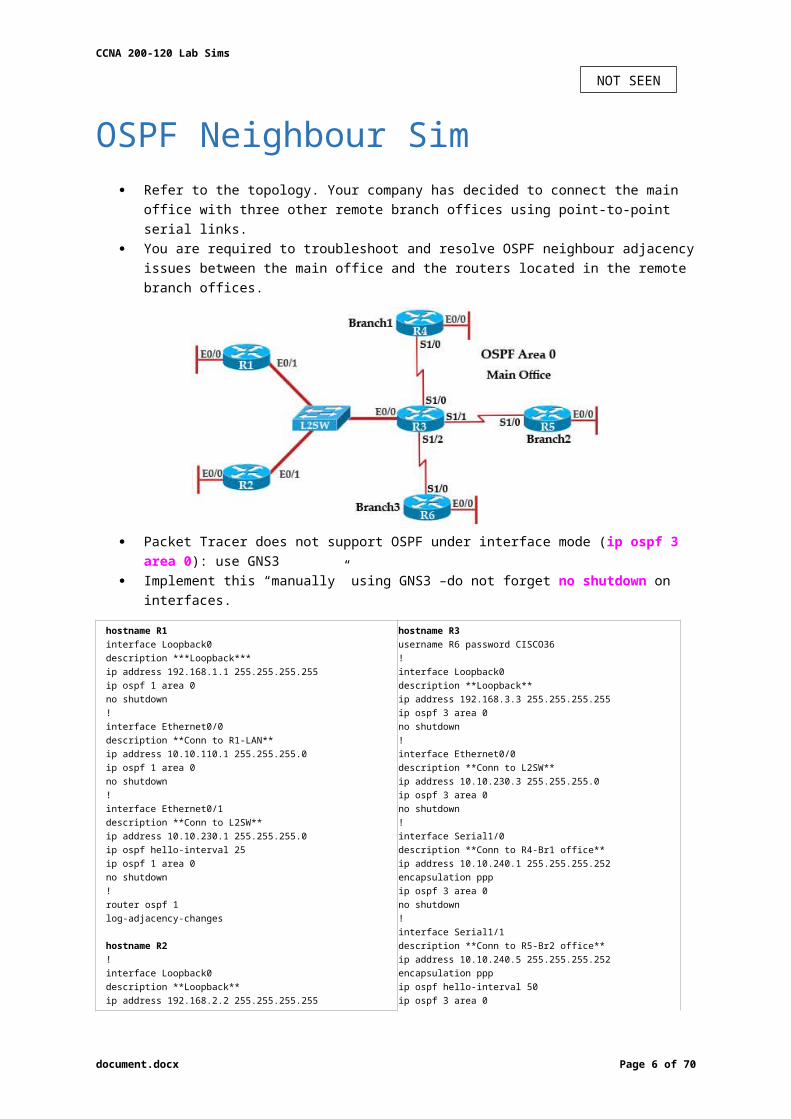
OSPF Neighbour Sim Refer to the topology. Your company has decided to connect the main office with three other
remote branch offices using point-to-point serial links. You are required to troubleshoot and resolve OSPF neighbour adjacency issues between the
main office and the routers located in the remote branch offices.
Packet Tracer does not support OSPF under interface mode (ip ospf 3 area 0): use GNS3 Implement this “manually” using GNS3 –do not forget no shutdown on interfaces.
hostname R1interface Loopback0description ***Loopback***ip address 192.168.1.1 255.255.255.255ip ospf 1 area 0no shutdown!interface Ethernet0/0description **Conn to R1-LAN**ip address 10.10.110.1 255.255.255.0ip ospf 1 area 0no shutdown!interface Ethernet0/1description **Conn to L2SW**ip address 10.10.230.1 255.255.255.0ip ospf hello-interval 25ip ospf 1 area 0no shutdown!router ospf 1log-adjacency-changes
hostname R2!interface Loopback0description **Loopback**ip address 192.168.2.2 255.255.255.255ip ospf 2 area 0no shutdown!interface Ethernet0/0description **Conn to R2-LAN**ip address 10.10.120.1 255.255.255.0ip ospf 2 area 0no shutdown!interface Ethernet0/1description **Conn to L2SW**ip address 10.10.230.2 255.255.255.0ip ospf 2 area 0no shutdown!router ospf 2
hostname R3username R6 password CISCO36!interface Loopback0description **Loopback**ip address 192.168.3.3 255.255.255.255ip ospf 3 area 0no shutdown!interface Ethernet0/0description **Conn to L2SW**ip address 10.10.230.3 255.255.255.0ip ospf 3 area 0no shutdown!interface Serial1/0description **Conn to R4-Br1 office**ip address 10.10.240.1 255.255.255.252encapsulation pppip ospf 3 area 0no shutdown!interface Serial1/1description **Conn to R5-Br2 office**ip address 10.10.240.5 255.255.255.252encapsulation pppip ospf hello-interval 50ip ospf 3 area 0no shutdown!interface Serial1/2description **Conn to R6-Br3 office**ip address 10.10.240.9 255.255.255.252encapsulation pppip ospf 3 area 0ppp authentication chapno shutdown!router ospf 3router-id 192.168.3.3!
document.docx Page 5 of 53
NOT SEEN
CCNA 200-120 Lab Sims
log-adjacency-changes
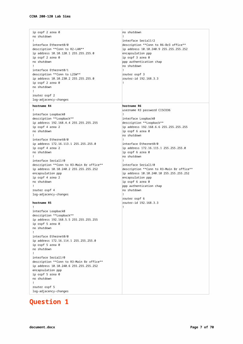
hostname R4!interface Loopback0description **Loopback**ip address 192.168.4.4 255.255.255.255ip ospf 4 area 2no shutdown!interface Ethernet0/0ip address 172.16.113.1 255.255.255.0ip ospf 4 area 2no shutdown!interface Serial1/0description **Conn to R3-Main Br office**ip address 10.10.240.2 255.255.255.252encapsulation pppip ospf 4 area 2no shutdown!router ospf 4log-adjacency-changes
hostname R5!interface Loopback0description **Loopback**ip address 192.168.5.5 255.255.255.255ip ospf 5 area 0no shutdown!interface Ethernet0/0ip address 172.16.114.1 255.255.255.0ip ospf 5 area 0no shutdown!interface Serial1/0description **Conn to R3-Main Br office**ip address 10.10.240.6 255.255.255.252encapsulation pppip ospf 5 area 0no shutdown!router ospf 5log-adjacency-changes
hostname R6username R3 password CISCO36!interface Loopback0description **Loopback**ip address 192.168.6.6 255.255.255.255ip ospf 6 area 0no shutdown!interface Ethernet0/0ip address 172.16.115.1 255.255.255.0ip ospf 6 area 0no shutdown!interface Serial1/0description **Conn to R3-Main Br office**ip address 10.10.240.10 255.255.255.252encapsulation pppip ospf 6 area 0ppp authentication chapno shutdown!router ospf 6router-id 192.168.3.3!
Question 1 An OSPF neighbour adjacency is not formed between R3 in the main office and R4 in the
Branch1 office. What is causing the problem?
A. There is an area ID mismatch.B. There is a Layer 2 issue; an encapsulation mismatch on serial links.C. There is an OSPF hello and dead interval mismatch.D. The R3 router ID is configured on R4.
We learned it is a OSPF problem so we should check the interfaces between them first. On both R3 and R4 use “show running-config” command to check their S1/0 interfaces
R3#show running-config<<output omitted>>!interface Serial1/0description **Conn to R4-Br1 office**ip address 10.10.240.1 255.255.255.252encapsulation pppip ospf 3 area 0 !<<output omitted>>
R4#show running-config<<output omitted>>!interface Serial1/0description **Conn to R3-Main Br office**ip address 10.10.240.2 255.255.255.252encapsulation pppip ospf 4 area 2 DO NOT FORGET the 4 area 2!<<output omitted>>
In the output above we see their Area IDs are mismatched; interface S1/0 of R3 is in area 0 (R3: ip ospf 3 area 0) while interface S1/0 of R4 is in area 2 (R4: ip ospf 4 area 2).
document.docx Page 6 of 53
A
CCNA 200-120 Lab Sims
Question 2 An OSPF neighbour adjacency is not formed between R3 in the main office and R5 in the
Branch2 office. What is causing the problem?
A. There is an area ID mismatch.B. There is a PPP authentication issue; a password mismatch.C. There is an OSPF hello and dead interval mismatch.D. There is a missing network command in the OSPF process on R5.
Continue checking their connected interfaces with the “show running-config” command:
R3#show running-config<<output omitted>>!interface Serial1/1description **Conn to R5-Br2 office**ip address 10.10.240.5 255.255.255.252encapsulation pppip ospf hello-interval 50 ip ospf 3 area 0!<<output omitted>>
R5#show running-config<<output omitted>>!interface Serial1/0description **Conn to R3-Main Br office**ip address 10.10.240.6 255.255.255.252encapsulation pppip ospf 5 area 0!<<output omitted>>
The only difference we can see here is the line “ip ospf hello-interval 50″ on R3.
o Command sets seconds R3 waits before sending next hello packet out this interface. o In this case R3 will send hello packets to R5 every 50 seconds. o But the default value of hello-interval is 10 seconds and R5 is using it. o Therefore, we can think of a hello interval mismatch problem here.
You can verify with the “show ip ospf interface <interface>” command on each router.R3#sh ip ospf int s1/1Serial1/1 is up, line protocol is upInternet Address 10.10.240.5/30, Area 0Process ID 3, Router ID 192.168.3.3, Network Type POINT_TO_POINT, Cost: 64Enabled by interface config, including secondary ip addressesTransmit Delay is 1 sec, State POINT_TO_POINT,Timer intervals configured, Hello 50, Dead 200, Wait 200, Retransmit 5oob-resync timeout 200Hello due in 00:00:28Supports Link-local Signaling (LLS)Index 2/2, flood queue length 0Next 0×0(0)/0×0(0)Last flood scan length is 0, maximum is 0Last flood scan time is 0 msec, maximum is 0 msecNeighbor Count is 0, Adjacent neighbor count is 0Suppress hello for 0 neighbor(s)
R5#sh ip ospf int s1/0Serial1/0 is up, line protocol is upInternet Address 10.10.240.6/30, Area 0Process ID 5, Router ID 10.10.240.6, Network Type POINT_TO_POINT, Cost: 64Enabled by interface config, including secondary ip addressesTransmit Delay is 1 sec, State POINT_TO_POINT,Timer intervals configured, Hello 10, Dead 40, Wait 40, Retransmit 5oob-resync timeout 40Hello due in 00:00:04Supports Link-local Signaling (LLS)Index 1/1, flood queue length 0Next 0×0(0)/0×0(0)Last flood scan length is 0, maximum is 0Last flood scan time is 0 msec, maximum is 0 msecNeighbor Count is 0, Adjacent neighbor count is 0Suppress hello for 0 neighbor(s)
B hello and dead interval are mismatched because the dead interval always four times the value of hello interval, unless you manually configure the dead interval (with the ip ospf dead-interval <seconds> command).
document.docx Page 7 of 53
C

CCNA 200-120 Lab Sims
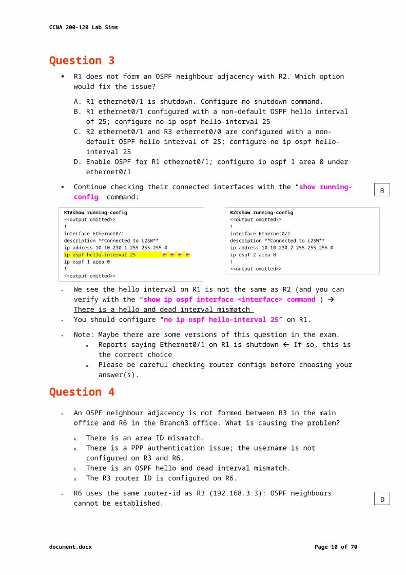
Question 3 R1 does not form an OSPF neighbour adjacency with R2. Which option would fix the issue?
A. R1 ethernet0/1 is shutdown. Configure no shutdown command.B. R1 ethernet0/1 configured with a non-default OSPF hello interval of 25; configure no ip
ospf hello-interval 25C. R2 ethernet0/1 and R3 ethernet0/0 are configured with a non-default OSPF hello interval
of 25; configure no ip ospf hello-interval 25D. Enable OSPF for R1 ethernet0/1; configure ip ospf 1 area 0 under ethernet0/1
Continue checking their connected interfaces with the “show running-config” command:
R1#show running-config<<output omitted>>!interface Ethernet0/1description **Connected to L2SW**ip address 10.10.230.1 255.255.255.0ip ospf hello-interval 25 ip ospf 1 area 0!<<output omitted>>
R2#show running-config<<output omitted>>!interface Ethernet0/1description **Connected to L2SW**ip address 10.10.230.2 255.255.255.0ip ospf 2 area 0!<<output omitted>>
We see the hello interval on R1 is not the same as R2 (and you can verify with the “show ip ospf interface <interface> command”) There is a hello and dead interval mismatch
You should configure “no ip ospf hello-interval 25″ on R1.
Note: Maybe there are some versions of this question in the exam. o Reports saying Ethernet0/1 on R1 is shutdown If so, this is the correct choice o Please be careful checking router configs before choosing your answer(s).
Question 4 An OSPF neighbour adjacency is not formed between R3 in the main office and R6 in the
Branch3 office. What is causing the problem?
A. There is an area ID mismatch.B. There is a PPP authentication issue; the username is not configured on R3 and R6.C. There is an OSPF hello and dead interval mismatch. D. The R3 router ID is configured on R6.
R6 uses the same router-id as R3 (192.168.3.3): OSPF neighbours cannot be established. In real life, such configuration error will be shown in the command line interface (CLI).
R3#show running-config<<output omitted>>username R6 password CISCO36!interface Serial1/2description **Conn to R6-Br3 office**ip address 10.10.240.9 255.255.255.252encapsulation pppip ospf 3 area 0ppp authentication chap!<<output omitted>>!router ospf 3router-id 192.168.3.3 ISSUE!<<output omitted>>
R6#show running-config<<output omitted>>username R3 password CISCO36!interface Serial1/0description **Conn to R3-Main Br office**ip address 10.10.240.10 255.255.255.252encapsulation pppip ospf 6 area 0ppp authentication chap!<<output omitted>>!router ospf 6router-id 192.168.3.3 ISSUE!<<output omitted>>
We are not sure about the configuration of ppp authentication in this case. o Some reports said that only one router has the “ppp authentication chap” command o It is just a trick and is not the problem here.
document.docx Page 8 of 53
D
B

CCNA 200-120 Lab Sims
So please check carefully for this question.
Comments New Questions
Q1. The loopback interfaces on R4 with the IP addresses of 10.4.4.4/32, 10.4.4.5/32 and 10.4.4.6/32 are:
R4 and R5 is same AS number but R4 don’t advertised all loopback (10.4.4.4/32, 10.4.4.5/32 and 10.4.4.6/32).
Ans: The loopback addresses haven’t been advertised, & network command is missing on R4.
Q2. Which path does traffic take from R1 to R5?
Ans: The answer was that the packets will go R1->R2->R5 AND R1->R3->R5 with equal-cost balancing (sh ip route and you’ll see two possible routes to R5 with equal eigrp metric )
Q3. Router R6 does not form an EIGRP neighbour relationship correctly with router R1. What is the cause for this misconfiguration?
R6# show run Router 6<<output omitted>>router eigrp 1network 10.6.6.6 0.0.0.0network 192.168.16.0metric weights 0 0 0 1 1 1 so the correct answer is The K values mismatch.auto-summary
Q4. Study the following output taken on R1:
R1#ping 10.5.5.55 source 10.1.1.1. . . . .Success rate is 0 percent (0/5)
Why are the pings failing?
R1 is advertised network 10.1.1.1 in EIGRP. But R5 isn’t advertised network 10.5.5.5.55 in EIGRP.
Ans: So the correct answer is “The network statement is missing on R5”
document.docx Page 9 of 53
SOME ASPECTS FROM HERE SEEN
CCNA 200-120 Lab Sims
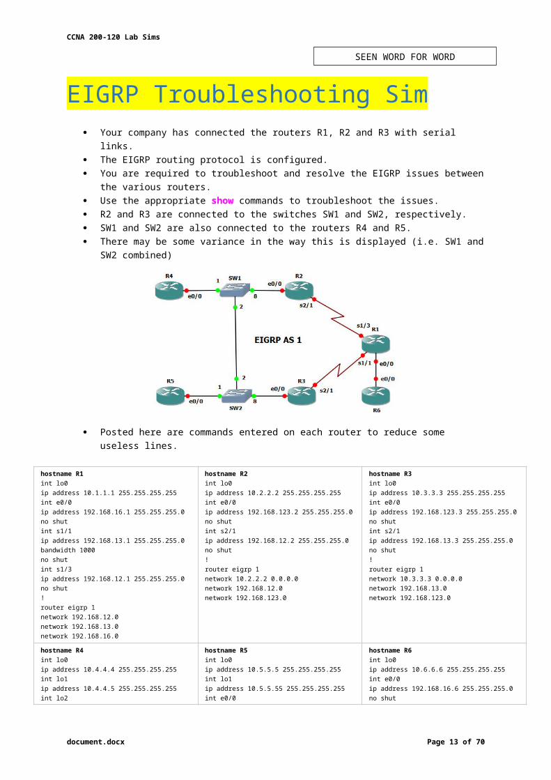
EIGRP Troubleshooting Sim Your company has connected the routers R1, R2 and R3 with serial links. The EIGRP routing protocol is configured. You are required to troubleshoot and resolve the EIGRP issues between the various routers. Use the appropriate show commands to troubleshoot the issues. R2 and R3 are connected to the switches SW1 and SW2, respectively. SW1 and SW2 are also connected to the routers R4 and R5. There may be some variance in the way this is displayed (i.e. SW1 and SW2 combined)
Posted here are commands entered on each router to reduce some useless lines.
hostname R1int lo0ip address 10.1.1.1 255.255.255.255int e0/0ip address 192.168.16.1 255.255.255.0no shutint s1/1ip address 192.168.13.1 255.255.255.0bandwidth 1000no shutint s1/3ip address 192.168.12.1 255.255.255.0no shut!router eigrp 1network 192.168.12.0network 192.168.13.0network 192.168.16.0
hostname R2int lo0ip address 10.2.2.2 255.255.255.255int e0/0ip address 192.168.123.2 255.255.255.0no shutint s2/1ip address 192.168.12.2 255.255.255.0no shut! router eigrp 1network 10.2.2.2 0.0.0.0network 192.168.12.0network 192.168.123.0
hostname R3int lo0ip address 10.3.3.3 255.255.255.255int e0/0ip address 192.168.123.3 255.255.255.0no shutint s2/1ip address 192.168.13.3 255.255.255.0no shut! router eigrp 1network 10.3.3.3 0.0.0.0network 192.168.13.0network 192.168.123.0
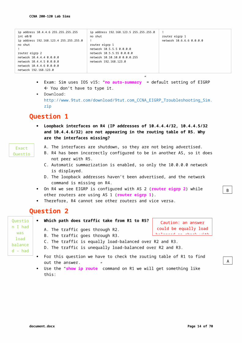
hostname R4int lo0ip address 10.4.4.4 255.255.255.255int lo1ip address 10.4.4.5 255.255.255.255int lo2ip address 10.4.4.6 255.255.255.255int e0/0ip address 192.168.123.4 255.255.255.0no shut!router eigrp 2network 10.4.4.4 0.0.0.0network 10.4.4.5 0.0.0.0network 10.4.4.6 0.0.0.0network 192.168.123.0
hostname R5int lo0ip address 10.5.5.5 255.255.255.255int lo1ip address 10.5.5.55 255.255.255.255int e0/0ip address 192.168.123.5 255.255.255.0no shut!router eigrp 1network 10.5.5.5 0.0.0.0network 10.5.5.55 0.0.0.0network 10.10.10.0 0.0.0.255network 192.168.123.0
hostname R6int lo0ip address 10.6.6.6 255.255.255.255int e0/0ip address 192.168.16.6 255.255.255.0no shut!router eigrp 1network 10.6.6.6 0.0.0.0
Exam: Sim uses IOS v15: “no auto-summary” = default setting of EIGRP You don’t have to type it.
Download: http://www.9tut.com/download/9tut.com_CCNA_EIGRP_Troubleshooting_Sim.zip
document.docx Page 10 of 53
SEEN WORD FOR WORD

CCNA 200-120 Lab Sims
Question 1 Loopback interfaces on R4 (IP addresses of 10.4.4.4/32, 10.4.4.5/32 and 10.4.4.6/32) are
not appearing in the routing table of R5. Why are the interfaces missing?
A. The interfaces are shutdown, so they are not being advertised.B. R4 has been incorrectly configured to be in another AS, so it does not peer with R5.C. Automatic summarization is enabled, so only the 10.0.0.0 network is displayed.D. The loopback addresses haven’t been advertised, and the network command is missing
on R4. On R4 we see EIGRP is configured with AS 2 (router eigrp 2) while other routers are using
AS 1 (router eigrp 1). Therefore, R4 cannot see other routers and vice versa.
Question 2 Which path does traffic take from R1 to R5?
A. The traffic goes through R2.B. The traffic goes through R3.C. The traffic is equally load-balanced over R2 and R3.D. The traffic is unequally load-balanced over R2 and R3.
For this question we have to check the routing table of R1 to find out the answer. Use the “show ip route” command on R1 we will get something like this:
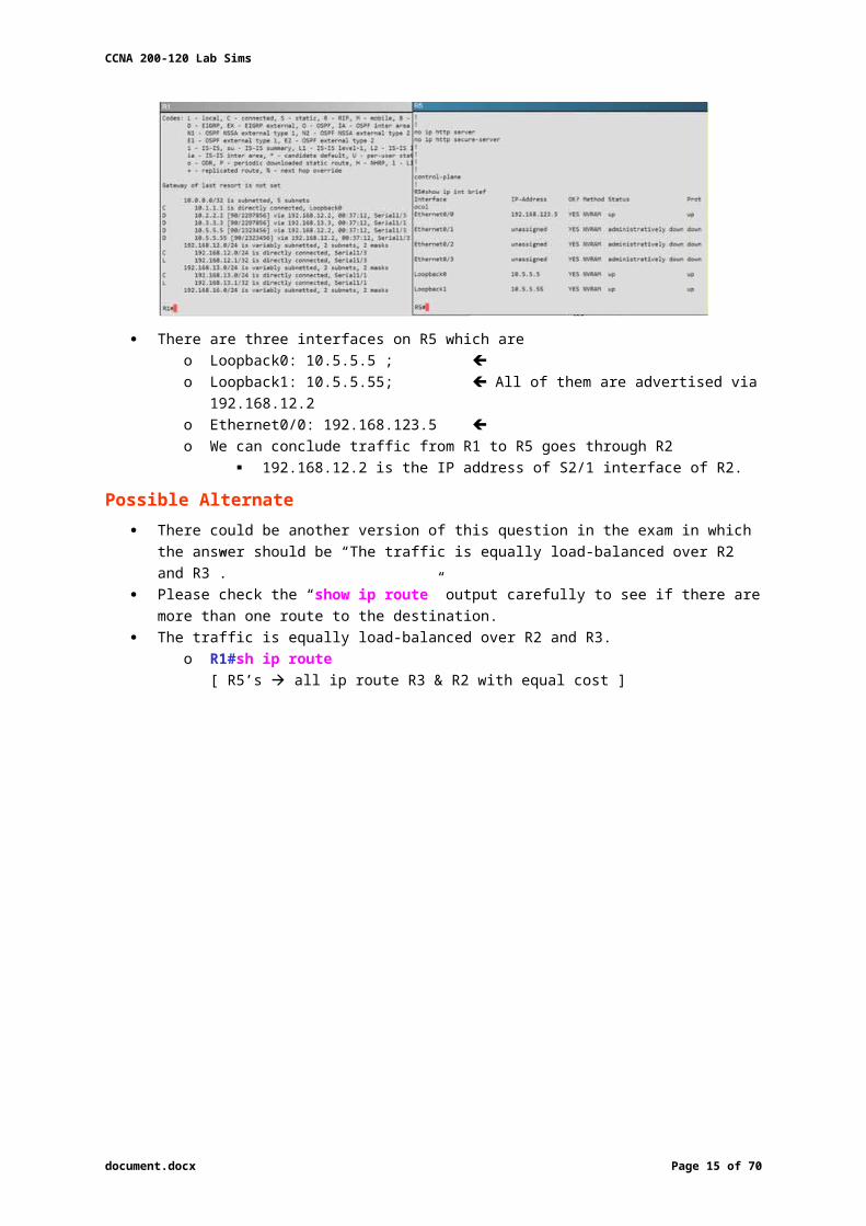
There are three interfaces on R5 which are o Loopback0: 10.5.5.5 ; o Loopback1: 10.5.5.55; All of them are advertised via 192.168.12.2o Ethernet0/0: 192.168.123.5 o We can conclude traffic from R1 to R5 goes through R2
192.168.12.2 is the IP address of S2/1 interface of R2.
Possible Alternate There could be another version of this question in the exam in which the answer should be
“The traffic is equally load-balanced over R2 and R3”. Please check the “show ip route” output carefully to see if there are more than one route to
the destination. The traffic is equally load-balanced over R2 and R3.
o R1#sh ip route[ R5’s all ip route R3 & R2 with equal cost ]
document.docx Page 11 of 53
Caution: an answer could be equally load balanced so check with show ip route
A
B
Question I had was
load balanced – had 2 routes in
table
Exact Question

CCNA 200-120 Lab Sims
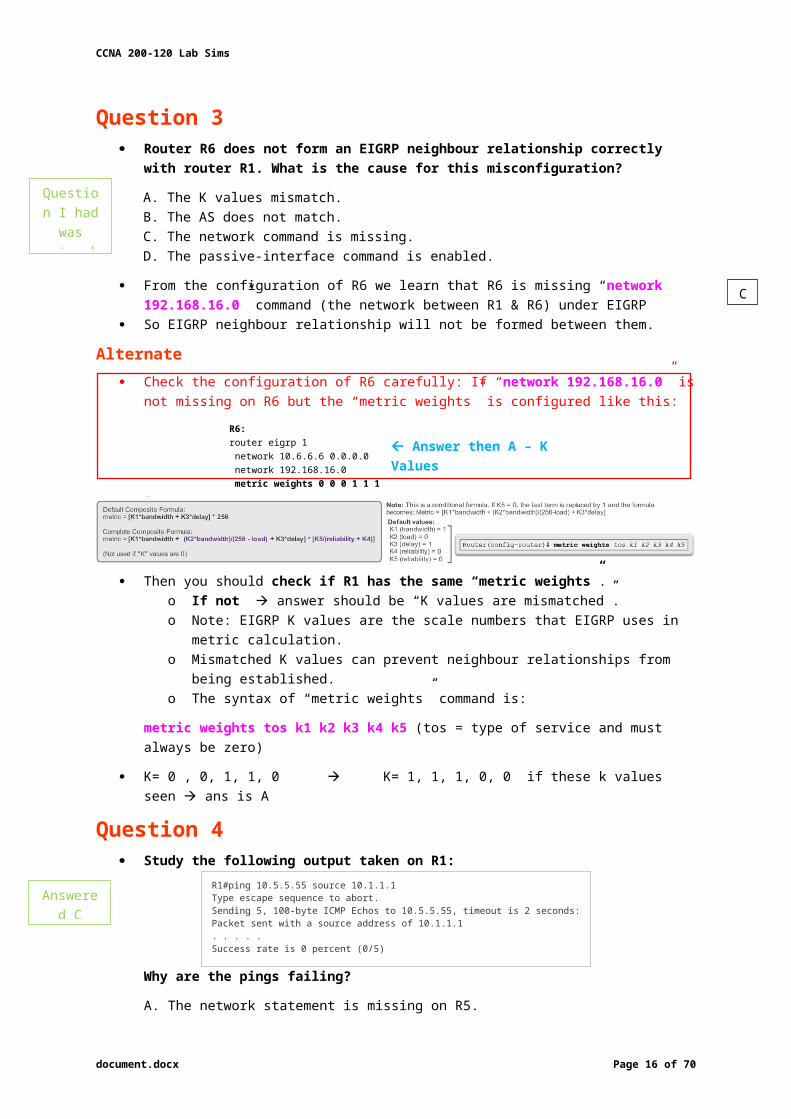
Question 3 Router R6 does not form an EIGRP neighbour relationship correctly with router R1.
What is the cause for this misconfiguration?
A. The K values mismatch.B. The AS does not match.C. The network command is missing.D. The passive-interface command is enabled.
From the configuration of R6 we learn that R6 is missing “network 192.168.16.0” command (the network between R1 & R6) under EIGRP
So EIGRP neighbour relationship will not be formed between them.
Alternate Check the configuration of R6 carefully: If “network 192.168.16.0” is not missing on R6 but
the “metric weights” is configured like this:
R6:router eigrp 1 network 10.6.6.6 0.0.0.0 network 192.168.16.0 metric weights 0 0 0 1 1 1
Answer then A – K Values
--
Then you should check if R1 has the same “metric weights”. o If not answer should be “K values are mismatched”.o Note: EIGRP K values are the scale numbers that EIGRP uses in metric calculation. o Mismatched K values can prevent neighbour relationships from being established. o The syntax of “metric weights” command is:
metric weights tos k1 k2 k3 k4 k5 (tos = type of service and must always be zero)
K= 0 , 0, 1, 1, 0 K= 1, 1, 1, 0, 0 if these k values seen ans is A
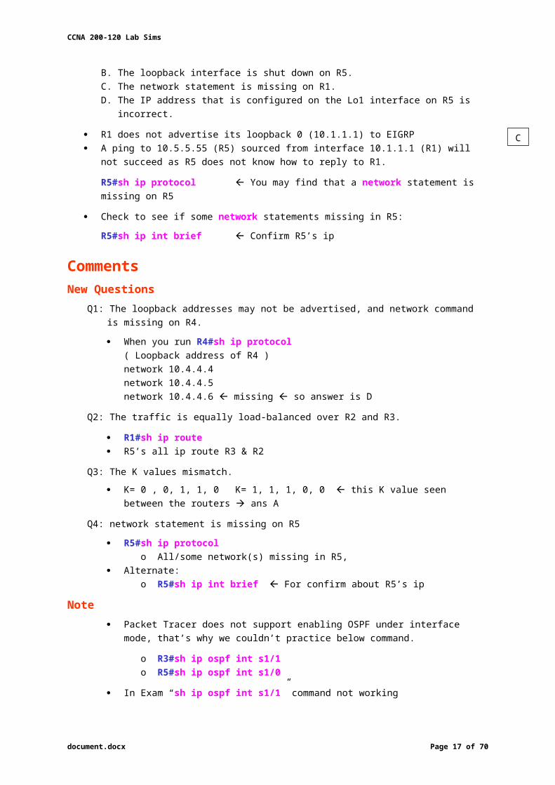
Question 4 Study the following output taken on R1:
R1#ping 10.5.5.55 source 10.1.1.1Type escape sequence to abort.Sending 5, 100-byte ICMP Echos to 10.5.5.55, timeout is 2 seconds:Packet sent with a source address of 10.1.1.1. . . . .Success rate is 0 percent (0/5)
Why are the pings failing?
A. The network statement is missing on R5.B. The loopback interface is shut down on R5.C. The network statement is missing on R1.D. The IP address that is configured on the Lo1 interface on R5 is incorrect.
R1 does not advertise its loopback 0 (10.1.1.1) to EIGRP A ping to 10.5.5.55 (R5) sourced from interface 10.1.1.1 (R1) will not succeed as R5 does not
know how to reply to R1.
R5#sh ip protocol You may find that a network statement is missing on R5
Check to see if some network statements missing in R5:
R5#sh ip int brief Confirm R5’s ip
document.docx Page 12 of 53
C
C
Question I had was network
command
Answered C
CCNA 200-120 Lab Sims
Comments
New QuestionsQ1: The loopback addresses may not be advertised, and network command is missing on R4.
When you run R4#sh ip protocol( Loopback address of R4 )network 10.4.4.4network 10.4.4.5network 10.4.4.6 missing so answer is D
Q2: The traffic is equally load-balanced over R2 and R3.
R1#sh ip route R5’s all ip route R3 & R2
Q3: The K values mismatch.
K= 0 , 0, 1, 1, 0 K= 1, 1, 1, 0, 0 this K value seen between the routers ans A
Q4: network statement is missing on R5
R5#sh ip protocolo All/some network(s) missing in R5,
Alternate:o R5#sh ip int brief For confirm about R5’s ip
Note Packet Tracer does not support enabling OSPF under interface mode, that’s why we
couldn’t practice below command.
o R3#sh ip ospf int s1/1o R5#sh ip ospf int s1/0
In Exam “sh ip ospf int s1/1” command not working
document.docx Page 13 of 53
CCNA 200-120 Lab Sims
VTP Sim This task requires you to use the CLI of Sw-AC3 to answer five multiple-choice questions. This task does not require any configuration. To answer the multiple-choice questions, click on the numbered boxes in the right panel.
There are five multiple-choice questions with this task; be sure to answer all five questions before leaving this item.
Download: http://www.goly.us/download/goly.us_CCNA_vtp_sim.pka
CAUTION: In this VTP sim, you have to answer 5 questions. After answering the first question, click on the number boxes to move to other questions. If you click “Next” at the first question, you will lose points for 4 remaining questions.
Question 1 What interface did Sw-AC3 associate with source MAC address 0010.5a0c.ffba ?
A. Fa0/1B. Fa0/3
C. Fa0/6D. Fa0/8
E. Fa0/9F. Fa0/12
To find the interface associated with a given MAC: show mac address-table on Sw-AC3.o It shows the learned MAC addresses and their associated interfaces.
After entering this command, you will see a MAC address table like this:
From this table we can see that MAC address 0010.5a0c.ffba is associated with Fa0/8.
Note: There are some reports that the “show mac-address-table” command does not exist.
o If you cannot use “show mac-address-table” try “show mac address-table”.
Question 2 What ports on Sw-AC3 are operating as trunks (choose three)?
A. Fa0/1B. Fa0/3
C. Fa0/4D. Fa0/6
E. Fa0/9F. Fa0/12
document.docx Page 14 of 53
D
CCNA 200-120 Lab Sims
Use show interface trunk to determine the trunking status of a link and VLAN status. o This command lists port, its mode, encapsulation and whether it is trunking.
Demonstration image (may not appear as this in reality):
Question 3 What kind of router is VLAN-R1?
A. 1720B. 1841
C. 2611D. 2620
VLAN-R1 is the router directly connected to Sw-Ac3 switch , so we can use the show cdp neighbors command to see:
1. Neighbor Device ID: The name of the neighbour device;2. Local Interface: The interface to which this neighbour is heard3. Capability: Capability of neighbouring device – R for router, S for switch, H for Host etc.4. Platform: Which type of device the neighbour is5. Port ID: The interface of the remote neighbour you receive CDP information6. Holdtime: Decremental hold time in seconds
Sample output of show cdp neighbors command (note: 2600 shown instead of 2620):
One thing I want to notice you is “Local Intrfce” in the image above refers to the local interface on the device you are running the “show cdp neighbors” command
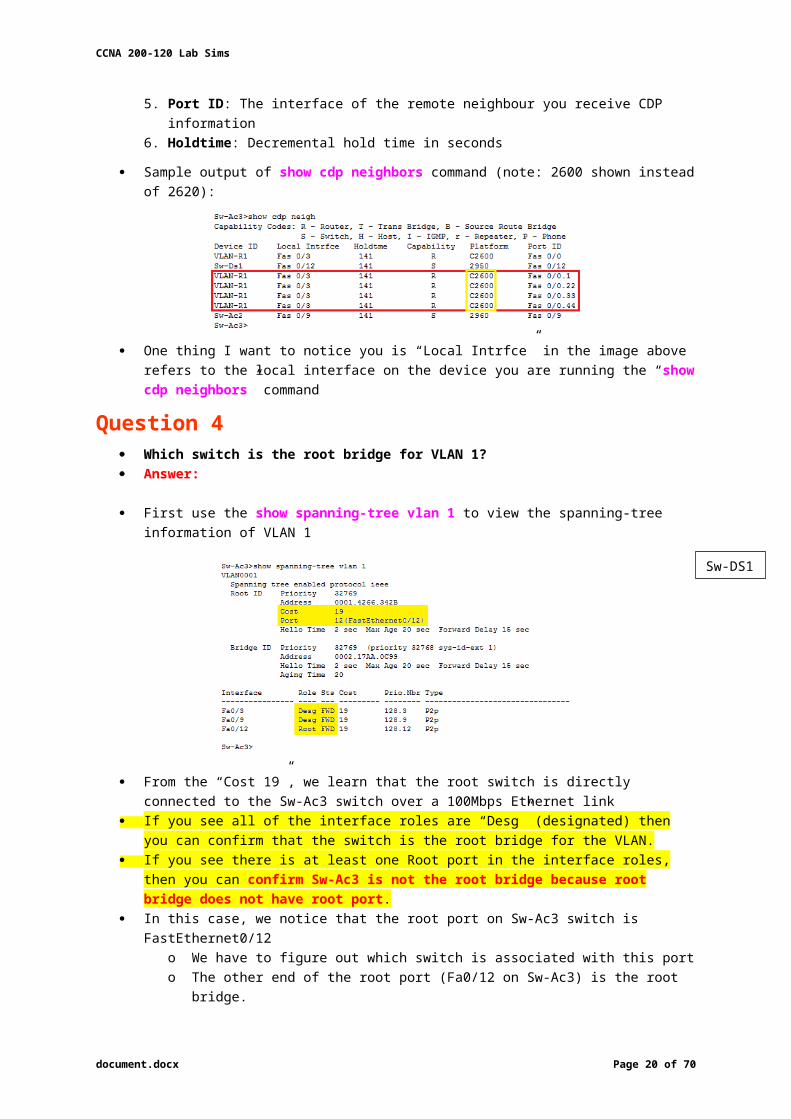
Question 4 Which switch is the root bridge for VLAN 1? Answer:
First use the show spanning-tree vlan 1 to view the spanning-tree information of VLAN 1
document.docx Page 15 of 53
BEF
D
Sw-DS1
CCNA 200-120 Lab Sims
From the “Cost 19”, we learn that the root switch is directly connected to the Sw-Ac3 switch over a 100Mbps Ethernet link
If you see all of the interface roles are “Desg” (designated) then you can confirm that the switch is the root bridge for the VLAN.
If you see there is at least one Root port in the interface roles, then you can confirm Sw-Ac3 is not the root bridge because root bridge does not have root port.
In this case, we notice that the root port on Sw-Ac3 switch is FastEthernet0/12o We have to figure out which switch is associated with this port o The other end of the root port (Fa0/12 on Sw-Ac3) is the root bridge.
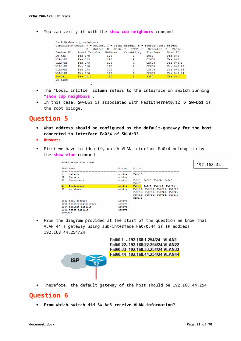
You can verify it with the show cdp neighbors command:
The “Local Intrfce” column refers to the interface on switch running “show cdp neighbors”. In this case, Sw-DS1 is associated with FastEthernet0/12 Sw-DS1 is the root bridge.
Question 5 What address should be configured as the default-gateway for the host connected to
interface Fa0/4 of SW-Ac3? Answer:
First we have to identify which VLAN interface Fa0/4 belongs to by the show vlan command
From the diagram provided at the start of the question we know that VLAN 44’s gateway using sub-interface Fa0/0.44 is IP address 192.168.44.254/24
document.docx Page 16 of 53
192.168.44.254
CCNA 200-120 Lab Sims
Therefore, the default gateway of the host should be 192.168.44.254
Question 6 From which switch did Sw-Ac3 receive VLAN information? Answer:
To view the VTP configuration information, use the show vtp status command:
So we knew Sw-Ac3 received VLAN information from 163.5.8.3
o Note: the IP address may be different to what is shown above (it is 1.1.1.1 in the Packet Tracer exercise)
show cdp neighbors detail Find out who 163.5.8.3 is:
Possible Alternate
If in the exam you find that “Configuration last modified by 0.0.0.0” then “0.0.0.0” here indicates it does not receive VLAN information from anyone Sw-Ac3 is also the local updater. The answer in this case is Sw-Ac3.
Question 7 Refer to the exhibit. SwX was taken out of the production network for maintenance. It
will be reconnected to the Fa 0/16 port of Sw-Ac3. What happens to the network when it is reconnected and a trunk exists between the two switches?
document.docx Page 17 of 53
Sw-AC2

CCNA 200-120 Lab Sims
A. All VLANs except the default VLAN will be removed from all switchesB. All existing switches will have the students, admin, faculty, Servers, Management,
Production, and no-where VLANsC. The VLANs Servers, Management, Production and no-where will replace the VLANs on
SwXD. The VLANs Servers, Management, Production and no-where will be removed from
existing switches
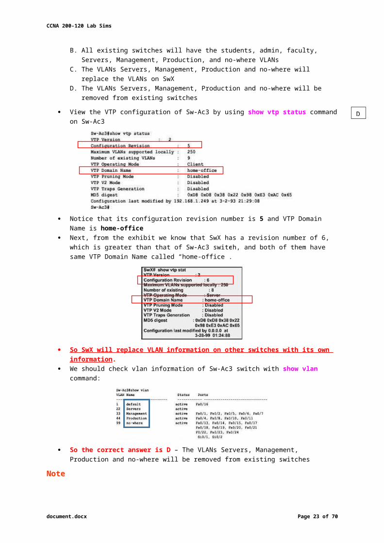
View the VTP configuration of Sw-Ac3 by using show vtp status command on Sw-Ac3
Notice that its configuration revision number is 5 and VTP Domain Name is home-office Next, from the exhibit we know that SwX has a revision number of 6, which is greater than
that of Sw-Ac3 switch, and both of them have same VTP Domain Name called “home-office”.
So SwX will replace VLAN information on other switches with its own information . We should check vlan information of Sw-Ac3 switch with show vlan command:
So the correct answer is D – The VLANs Servers, Management, Production and no-where will be removed from existing switches
Note In the real CCNA exam you may see a different configuration revision of Sw-Ac3 or of SwX.
document.docx Page 18 of 53
D

CCNA 200-120 Lab Sims
In general, the switch that has a higher revision number will become the updater. Check mode: Client, Transparent, Server Other switches will overwrite their current databases with the new information received
from the updater, provided that they are on the same domain and that switch is not in transparent mode.
o In particular, if the revision number of SwX is lower than that of Sw-Ac3, the answer should be “C – The VLANs Servers, Management, Production and no-where will replace the VLANs on SwX”.
o Also, some recent comments have said that the new switch’s VTP Operating Mode is Server but the answer is still the same.
Note: If a switch is in client mode and has a higher Revision number, it can still update other Server switches (with lower Revision numbers).
Question 8 Out of which ports will a frame be forwarded that has source mac-address
0010.5a0c.fd86 and destination mac-address 000a.8a47.e612? (Choose three)A. Fa0/8B. Fa0/3
C. Fa0/1D. Fa0/12
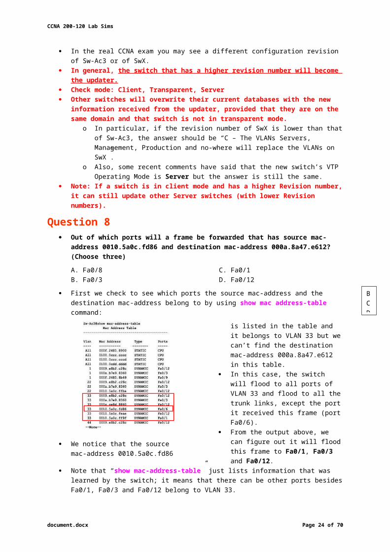
First we check to see which ports the source mac-address and the destination mac-address belong to by using show mac address-table command:
We notice that the source mac-address 0010.5a0c.fd86 is listed in the table and it belongs to VLAN 33 but we can’t find the destination mac-address 000a.8a47.e612 in this table.
In this case, the switch will flood to all ports of VLAN 33 and flood to all the trunk links, except the port it received this frame (port Fa0/6).
From the output above, we can figure out it will flood this frame to Fa0/1, Fa0/3 and Fa0/12.
Note that “show mac-address-table” just lists information that was learned by the switch; it means that there can be other ports besides Fa0/1, Fa0/3 and Fa0/12 belong to VLAN 33.
You can use the show vlan command to see which ports belong to vlan 33
And we found other ports which belong to vlan 33, they are Fa0/2, Fa0/5 and Fa0/7. o Our switch will flood the frame to these ports, too.
We can check which trunk ports will receive this frame using show interface trunk:
Port Fa0/9 will also receive this frame!
document.docx Page 19 of 53
BCD
CCNA 200-120 Lab Sims
Reports: Alternate Question Version What will be the destination MAC address of a packet with Source IP address
192.168.44.1 and destination IP address 192.0.2.X?
o It does not matter what the Dest. IP address will be since it will be sent to the router.
Answer: Since the source IP address belongs to VLAN 44, the default gw of the sender is the Router’s Subinterface 192.168.44.254, and this is where the packet will be sent.
o Perform a show cdp neighbors on the Sw-AC3 to find the local FastEthernet port where the router is connected.
o Then execute a show mac address-table and find the mac address associated with the previous port. This gives the answer.
Question 9 If one of the host connected to Sw-AC3 wants to send something for the ip 190.0.2.5 (or
any ip that is not on the same subnet) what will be the destination MAC address? Answer:
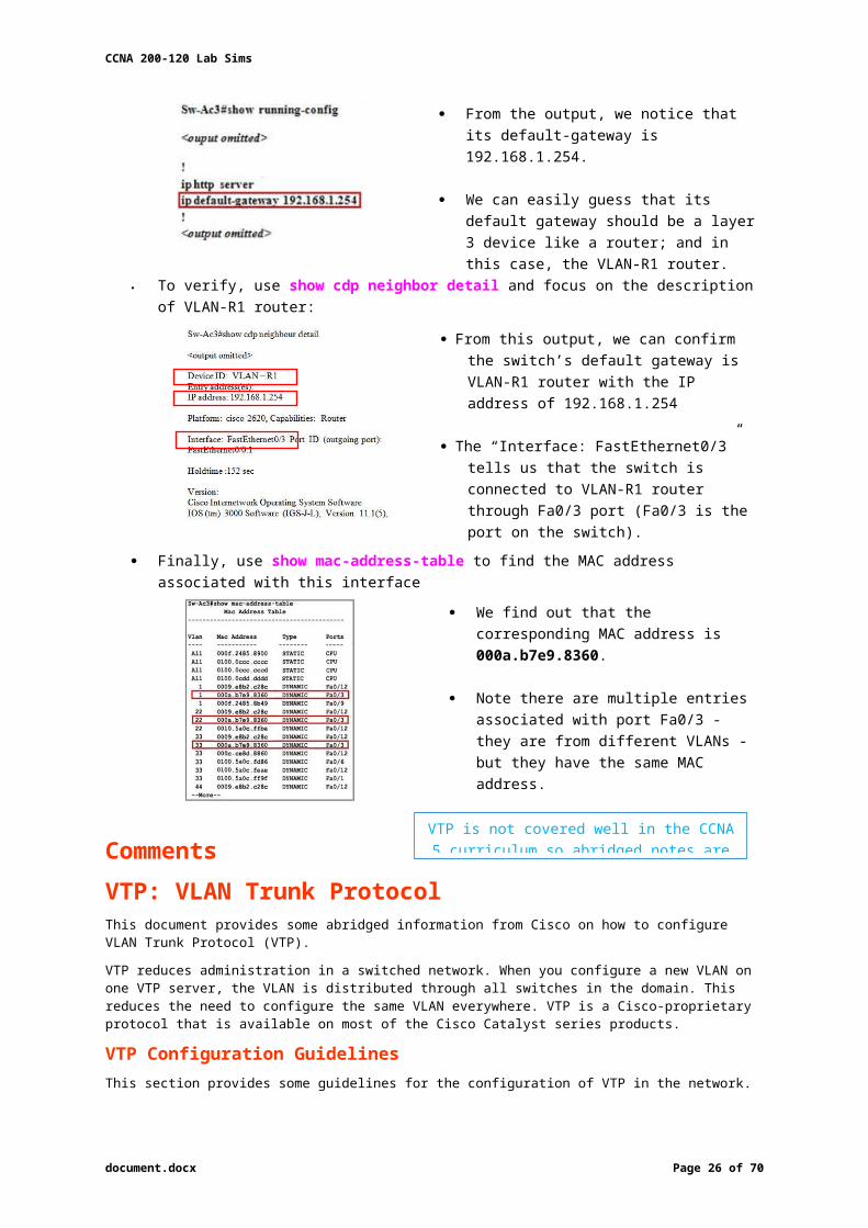
As the destination address is not on the same subnet with the switch, it will forward the packet to its default gateway we have to find out who is the default gateway of this switch by using show running-config:
From the output, we notice that its default-gateway is 192.168.1.254.
We can easily guess that its default gateway should be a layer 3 device like a router; and in this case, the VLAN-R1 router.
To verify, use show cdp neighbor detail and focus on the description of VLAN-R1 router:
From this output, we can confirm the switch’s default gateway is VLAN-R1 router with the IP address of 192.168.1.254
The “Interface: FastEthernet0/3” tells us that the switch is connected to VLAN-R1 router through Fa0/3 port (Fa0/3 is the port on the switch).
Finally, use show mac-address-table to find the MAC address associated with this interface
We find out that the corresponding MAC address is 000a.b7e9.8360.
Note there are multiple entries associated with port Fa0/3 - they are from different VLANs - but they have the same MAC address.
document.docx Page 20 of 53
VTP is not covered well in the CCNA 5 curriculum so abridged notes are provided here
000a.b7e9.8360
CCNA 200-120 Lab Sims
Comments
VTP: VLAN Trunk ProtocolThis document provides some abridged information from Cisco on how to configure VLAN Trunk Protocol (VTP).
VTP reduces administration in a switched network. When you configure a new VLAN on one VTP server, the VLAN is distributed through all switches in the domain. This reduces the need to configure the same VLAN everywhere. VTP is a Cisco-proprietary protocol that is available on most of the Cisco Catalyst series products.
VTP Configuration Guidelines This section provides some guidelines for the configuration of VTP in the network.
All switches have the same the VTP domain name, unless the network design insists for different VTP domains.
Note: Trunk negotiation does not work across VTP domains.
All switches in a VTP domain must run the same VTP version. All switches in a VTP domain has the same VTP password, if there is any. All VTP Server switch(es) should have the same configuration revision number and it should also be the
highest in the domain. When you move a VTP mode of a switch from Transparent to Server, VLANs configured on the VTP
Transparent switch should exist on the Server switch.
VTP Configuration on Catalyst Switches There are two methods that you can use in order to configure VTP.
1. In VLAN database mode:
In Cisco IOS Software, you can configure the VTP domain name, the VTP mode, and the VLANs in VLAN configuration mode.
a. In EXEC mode, issue this command in order to enter VLAN configuration mode:
Router#vlan database
!--- Issue this command in privileged EXEC mode, !--- not in global configuration mode.Router(vlan)#
!--- This is VLAN configuration mode.
b. Issue this command in order to set the VTP domain name:
Router(vlan)#vtp domain domain-name
c. Issue this command in order to set the VTP mode:
Router(vlan)#vtp {client | server | transparent}
d. Issue the exit command in order to exit VLAN configuration mode.
2. In global configuration mode:
In Cisco IOS Software global configuration mode, you can configure all VTP parameters with Cisco IOS Software commands. This is the command format:Router(config)#vtp ?domain Set the name of the VTP administrative domain.file Configure IFS filesystem file where VTP configuration is stored.interface Configure interface as the preferred source for the VTP IP updater address. mode Configure VTP device modepassword Set the password for the VTP administrative domainpruning Set the administrative domain to permit pruningversion Set the administrative domain to VTP version
3. Issue these commands in order to monitor VTP operation and status:
Router#show vtp statusRouter#show vtp counters
Catalyst 2900XL, 3500XL, 2950, and 3550
Complete these steps:
document.docx Page 21 of 53

CCNA 200-120 Lab Sims
1. Issue these commands from the VLAN database mode:Note: This is similar to the method for Cisco 6500 series switches that run Cisco IOS Software.
vtp [client | server | transparent]vtp domain name
2. From enable mode, issue these commands in order to monitor VTP operation:
show vtp countersshow vtp status
Note: The Catalyst 2900XL series switches with Cisco IOS Software Release 11.2(8)SA4 and later support VTP protocol. The Cisco IOS Software Release 11.2(8)SA3 and earlier code do not support VTP protocol on Catalyst 2900XL series switches.
document.docx Page 22 of 53
CCNA 200-120 Lab Sims
Access List Sim 1
Download: http://www.9tut.com/download/9tut.com_CCNA_Access_List_Sim.pkto Enable password is cisco
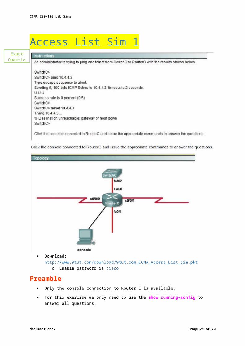
Preamble Only the console connection to Router C is available.
For this exercise we only need to use the show running-config to answer all questions.
Router>enableRouter#show running-config
Relevant sections of the running-config file are shown below:
document.docx Page 23 of 53
Exact Question
CCNA 200-120 Lab Sims
Question 1 How can we allow ping to work while disabling telnet?
A. Correctly assign an IP address to interface fa0/1B. Change the ip access-group command on fa0/0 from “in” to “out”C. Remove access-group 106 in from interface fa0/0 and add access-group 115 in. D. Remove access-group 102 out from interface s0/0/0 and add access-group 114 in E. Remove access-group 106 in from interface fa0/0 and add access-group 104 in
Interface fa0/0 is the interface that we are concerned about as it connects to the switch that we are trying to test
Question not about FTP: skip lines 1 & 2. Line #3 denies telnet traffic Line #4 permits icmp-echo traffic. Line #5 denies echo-reply traffic:
If a ping is sent to a device attached to Fa0/0, the packet will be denied. Line #6 permits all other traffic. The “access-list 106 permit any any” missing!
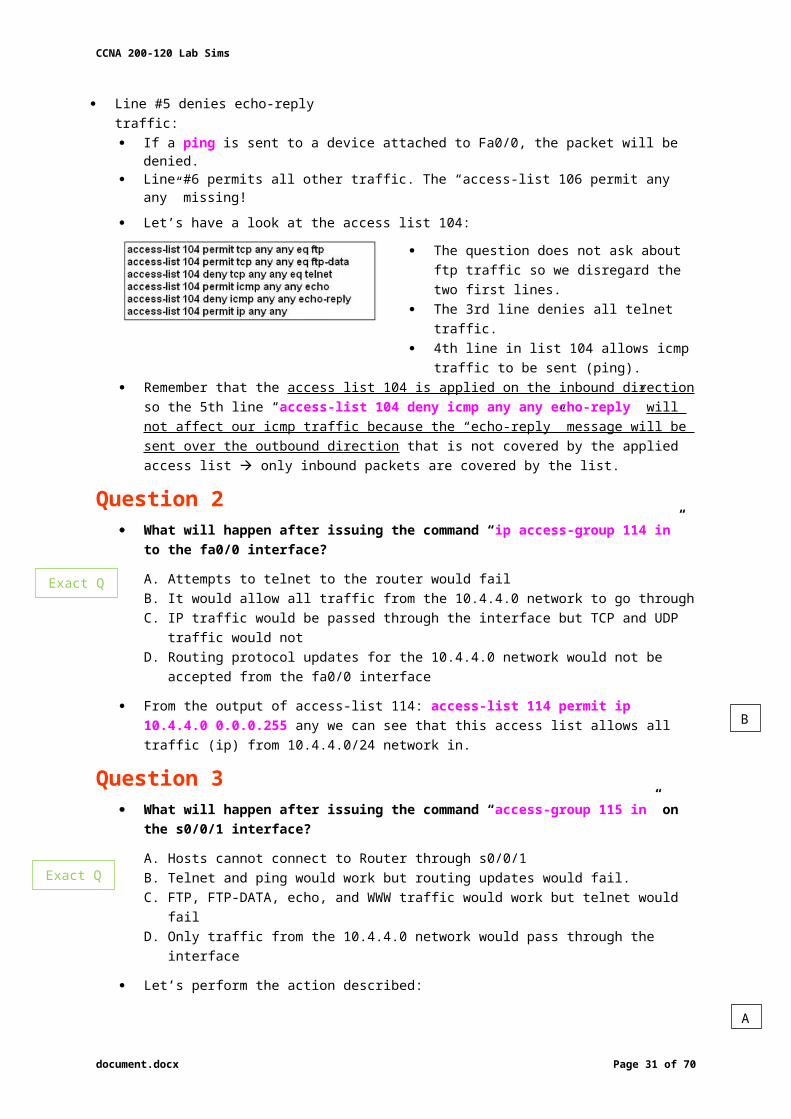
Let’s have a look at the access list 104:
The question does not ask about ftp traffic so we disregard the two first lines.
The 3rd line denies all telnet traffic. 4th line in list 104 allows icmp traffic to be
sent (ping).
Remember that the access list 104 is applied on the inbound direction so the 5th line “access-list 104 deny icmp any any echo-reply” will not affect our icmp traffic because the “echo-reply” message will be sent over the outbound direction that is not covered by the applied access list only inbound packets are covered by the list.
document.docx Page 24 of 53
Remember fa0/0 is the interface that connects to the switch and all ping and telnet services work on the router.
E
Slight reword of
Q

CCNA 200-120 Lab Sims
Question 2 What will happen after issuing the command “ip access-group 114 in” to the fa0/0
interface?
A. Attempts to telnet to the router would failB. It would allow all traffic from the 10.4.4.0 network to go throughC. IP traffic would be passed through the interface but TCP and UDP traffic would notD. Routing protocol updates for the 10.4.4.0 network would not be accepted from the fa0/0
interface
From the output of access-list 114: access-list 114 permit ip 10.4.4.0 0.0.0.255 any we can see that this access list allows all traffic (ip) from 10.4.4.0/24 network in.
Question 3 What will happen after issuing the command “access-group 115 in” on the s0/0/1
interface?
A. Hosts cannot connect to Router through s0/0/1B. Telnet and ping would work but routing updates would fail. C. FTP, FTP-DATA, echo, and WWW traffic would work but telnet would failD. Only traffic from the 10.4.4.0 network would pass through the interface
Let’s perform the action described:
access-list 115 permit ip 0.0.0.0 255.255.255.0 any Recall that each interface only accepts one access-list, so when using the command “ip access-group 115 in” on the s0/0/1 interface it will overwrite the initial access-list 102.
Therefore, any telnet connection will be accepted (so we can eliminate answer C).
B is not correct because if telnet and ping can work then routing updates can, too. D is not correct because access-list 115 does not mention about 10.4.4.0 network. So the most reasonable answer is A.
Comments
Q3 raises a question… The wildcard mask of access-list 115, which is 255.255.255.0, means that only host with ip addresses in the form of x.x.x.0 will be accepted.
o The wildcard mask of access-list 115 is 255.255.255.0, means that only host with IP addresses x.x.x.0 will be accepted.
o If the 4th part of an IP address is 0, then definitely it would be a network address. o So no host can communicate with another networks using S0/0/1 interface.o But it will accept the packet with source IP address – 10.10.0.0/8. The 4th octet is 0,
and is not a network address but a valid IP address. So confusion...o But we all know that x.x.x.0 is likely to be a network address so the answer A: “no
host could connect to Router through s0/0/1” seems right… But what will happen if we don’t use a subnet mask of 255.255.255.0?
o For example, we can use an ip address of 10.45.45.0 255.255.0.0, such a host with that ip address exists and we can connect to the router through that host.
o Now answer A seems incorrect!
document.docx Page 25 of 53
B
A
Exact Q
Exact Q
Pretty sure was another Q
CCNA 200-120 Lab Sims
Access List Sim 2 A network associate is adding security to the configuration of the Corp1 router. The user on
host C should be able to use a web browser to access financial information from the Finance Web Server. No other hosts from the LAN nor the Core should be able to use a web browser to access this server. Since there are multiple resources for the corporation at this location including other resources on the Finance Web Server, all other traffic should be allowed.
The task is to create and apply a numbered access-list with no more than three statements that will allow ONLY host C web access to the Finance Web Server. No other hosts will have web access to the Finance Web Server. All other traffic is permitted.
o Access to the router CLI can be gained by clicking on the appropriate host.o All passwords have been temporarily set to “cisco”.o The Core connection uses an IP address of 198.18.196.65o The computers in the Hosts LAN have been assigned addresses of 192.168.33.1 –
192.168.33.254 Host A 192.168.33.1 Host B 192.168.33.2 Host C 192.168.33.3 Host D 192.168.33.4
o The servers in the Server LAN have been assigned addresses of 172.22.242.17 – 172.22.242.30
o The Finance Web Server is assigned an IP address of 172.22.242.23.o The Public Web Server is assigned an IP address of 172.22.242.17
Some modifications about the access-list have been reported so you should read the “Some modifications” section at the end of this question to understand more.
Download: http://www.9tut.com/download/9tut.com_Access-list_sim2.pkt
SolutionCorp1>enable (you may enter “cisco” as it passwords here)
We should create an access-list and apply it to the interface which is connected to the Server LAN because it can filter out traffic from both Sw-2 and Core networks.
The Server LAN network has been assigned addresses of 172.22.242.17 – 172.22.242.30 so we can guess the interface connected to them has an IP address of 172.22.242.30
document.docx Page 26 of 53
Exact Q-
Different IP
As it is an extended list, Place as close as possible to source of traffic to be filtered

CCNA 200-120 Lab Sims
Use “show running-config” to check which interface has the IP address of 172.22.242.30.
Interface FastEthernet0/1 is the interface connected to Server LAN network: It is the interface we will apply our access-list (for outbound direction – which is closest to the source) to.
Corp1#configure terminal Our access-list needs to allow host C – 192.168.33.3 to the Finance Web Server
172.22.242.23 via web (port 80)
Corp1(config)#access-list 100 permit tcp host 192.168.33.3 host 172.22.242.23 eq 80
Deny other hosts access to the Finance Web Server via web
Corp1(config)#access-list 100 deny tcp any host 172.22.242.23 eq 80
All other traffic is permitted
Corp1(config)#access-list 100 permit ip any any
Apply this access-list to Fa0/1 interface (outbound direction)
Corp1(config)#interface fa0/1Corp1(config-if)#ip access-group 100 out
Note: We have to apply the access-list to Fa0/1 interface (not Fa0/0 interface) so that the access-list can filter traffic coming from both the LAN and the Core networks.
If we apply access list to the inbound interface we can only filter traffic from the LAN network.
In the exam, just click on host C to open its web browser. In the address box type http://172.22.242.23 to see if you can access the Finance Web
Server. o If your configuration is correct then you can access it.
Click on other hosts (A, B and D) and check to make sure you can’t access Finance Web Server from these hosts.
Finally, save the configuration
Corp1(config-if)#endCorp1#copy running-config startup-config
(This configuration only prevents hosts from accessing Finance Web Server via web but if this server supports other traffic – like FTP, SMTP… then other hosts can access it, too.)
Note: You might be asked to allow other host (A, B or D) to access the Finance Web Server so please read the requirement carefully.
document.docx Page 27 of 53

CCNA 200-120 Lab Sims
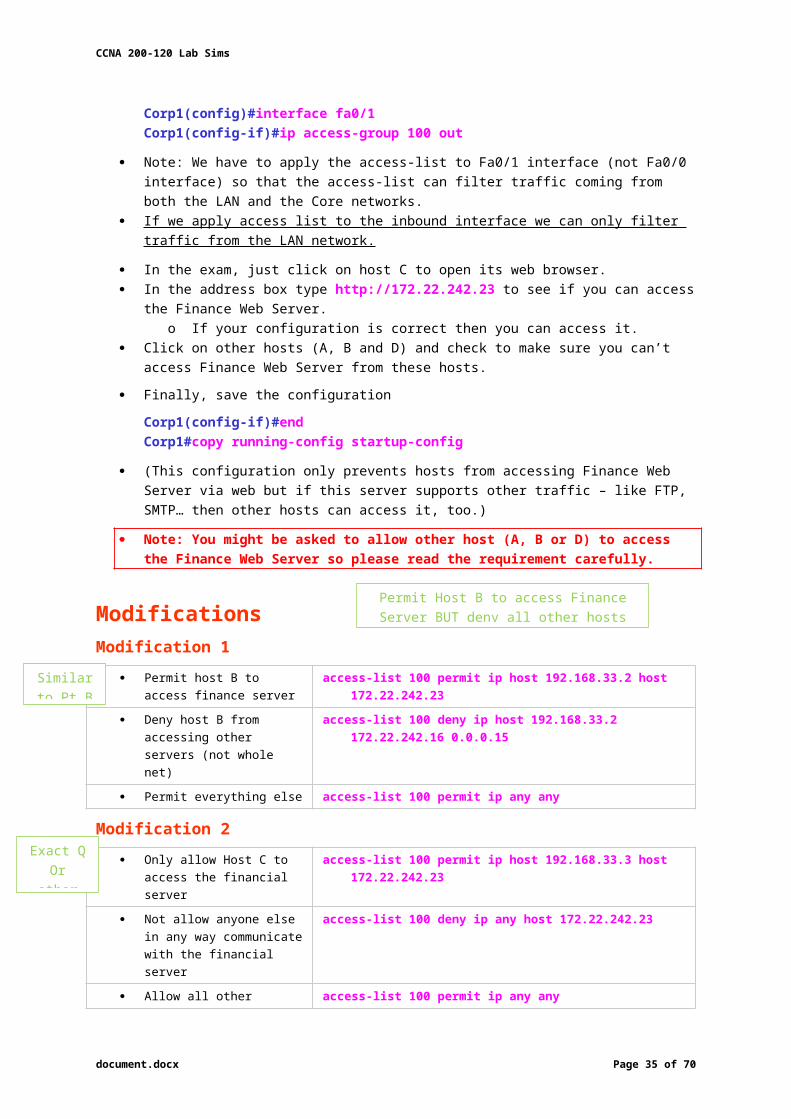
ModificationsModification 1
Permit host B to access finance server
access-list 100 permit ip host 192.168.33.2 host 172.22.242.23
Deny host B from accessing other servers (not whole net)
access-list 100 deny ip host 192.168.33.2 172.22.242.16 0.0.0.15
Permit everything else access-list 100 permit ip any any
Modification 2 Only allow Host C to access
the financial serveraccess-list 100 permit ip host 192.168.33.3 host 172.22.242.23
Not allow anyone else in any way communicate with the financial server
access-list 100 deny ip any host 172.22.242.23
Allow all other traffic access-list 100 permit ip any any
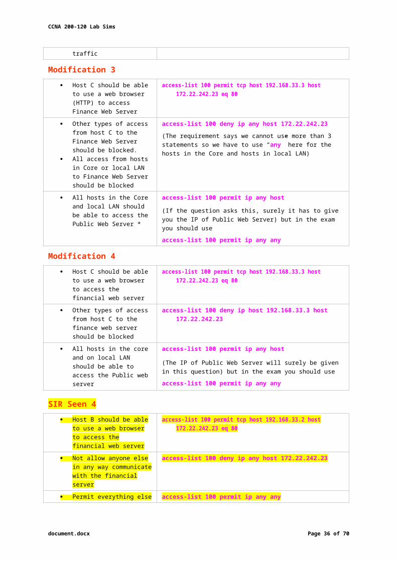
Modification 3 Host C should be able to use
a web browser (HTTP) to access Finance Web Server
access-list 100 permit tcp host 192.168.33.3 host 172.22.242.23 eq 80
Other types of access from host C to the Finance Web Server should be blocked.
All access from hosts in Core or local LAN to Finance Web Server should be blocked
access-list 100 deny ip any host 172.22.242.23(The requirement says we cannot use more than 3 statements so we have to use “any” here for the hosts in the Core and hosts in local LAN)
All hosts in the Core and local LAN should be able to access the Public Web Server *
access-list 100 permit ip any host
(If the question asks this, surely it has to give you the IP of Public Web Server) but in the exam you should use
access-list 100 permit ip any any
Modification 4 Host C should be able to use
a web browser to access the financial web server
access-list 100 permit tcp host 192.168.33.3 host 172.22.242.23 eq 80
Other types of access from host C to the finance web server should be blocked
access-list 100 deny ip host 192.168.33.3 host 172.22.242.23
All hosts in the core and on local LAN should be able to access the Public web server
access-list 100 permit ip any host
(The IP of Public Web Server will surely be given in this question) but in the exam you should use
access-list 100 permit ip any any
SIR Seen 4 Host B should be able to use
a web browser to access the financial web server
access-list 100 permit tcp host 192.168.33.2 host 172.22.242.23 eq 80
Not allow anyone else in any way communicate with the financial server
access-list 100 deny ip any host 172.22.242.23
document.docx Page 28 of 53
Exact QOr other servers
Similar to Pt B
Permit Host B to access Finance Server BUT deny all other hosts server access
CCNA 200-120 Lab Sims
Permit everything else access-list 100 permit ip any any
There are some reports about the command of “All hosts in the core and on the local LAN should be able to access the Public web server” saying that the correct command should be “access-list 100 permit ip any any”, not “access-list 100 permit ip any host (IP of Public Web Server)”.
Although I believe the second command is better but maybe you should use the first command “access-list 100 permit ip any any” instead as some reports said they got 100% when using this command (even if the question gives you the IP address of Public Web Server).
o It is a bug in this sim.
Do not forget to apply this access list to the suitable interface or you will lose points
interface fa0/1ip access-group 100 out
And in the exam, they will slightly change the requirements, for example host A, host B instead of host C… so make sure you read the requirement carefully and use the access-list correctly.
Simulation Practice Sim
Download: http://www.9tut.com/download/9tut.com_Access-list_sim2.pkt
Note: After typing the commands above, if you make a “ping” from other hosts (PC0, PC1, PC3) then PC4 (Finance Web Server) can still reply because we just filter HTTP traffic, not ICMP traffic.
To generate HTTP traffic, select “Web Browser” in the “Desktop” tab of these PCs. When a web browser opens, type the IP address of Finance Web Server and you can see
how traffic flows in Simulation Mode.
Note that in the initial configuration the Core network can ping Finance Web Server. We have to create an access-list that can filter this traffic too.
document.docx Page 29 of 53
Yes

CCNA 200-120 Lab Sims
Comments
There are some reports that in the exam, acl 2 line 2 shows 192.168.33.0 0.0.0.255 ? or “any”. ? o most comments say “any ” access-list 100 deny ip 192.168.33.0 0.0.0.255 host 172.22.242.23
Or access-list 100 deny ip any host 172.22.242.23
Is it correct to say the acl2 will be either like the first example or mod 1,2,3 or 4 (assuming IP’s different and may be a different host) ?
To clarify my question. hoping I don’t have to put this for line 2 :o access-list 100 deny ip 192.168.33.0 0.0.0.255 host 172.22.242.23
and instead use:o access-list 100 deny ip any host 172.22.242.23
ACL
The first ACL you mentioned would only deny the LAN hosts from reaching 172.22.242.23 but the second one would deny any host (including the core) from reaching 172.22.242.23
document.docx Page 30 of 53
CCNA 200-120 Lab Sims
NAT Sim 1 A network associate is configuring a router for the CCNA Training company to provide
internet access. The ISP has provided the company six public IP addresses of 198.18.184.105 198.18.184.110. The company has 14 hosts that need to access the internet simultaneously. The hosts in the CCNA Training company LAN have been assigned private space addresses in the range of 192.168.100.17 – 192.168.100.30.
The task is to complete the NAT configuration using all IP addresses assigned by the ISP to provide Internet access for the hosts in the Weaver LAN. Functionality can be tested by clicking on the host provided for testing.
The following have already been configured on the router:- The basic router configuration- The appropriate interfaces have been configured for NAT inside and NAT outside
– The appropriate static routes have also been configured (since the company will be a stub network, no routing protocol will be required.)
– All passwords have been temporarily set to “cisco”
Download: http://www.goly.us/download/goly.us_CCNA_NAT_sim_question.zip The CCNA Training company has 14 hosts that need to access the internet simultaneously
but we just have 6 public IP addresses from 198.18.184.105 to 198.18.184.110/29. o Therefore, we have to use NAT overload (or PAT)
document.docx Page 31 of 53

CCNA 200-120 Lab Sims
document.docx Page 32 of 53

CCNA 200-120 Lab Sims
Steps Double click on the Weaver router to open it
Router>enableRouter#configure terminal
First you should change the router’s name to Weaver
Router(config)#hostname Weaver Create a NAT pool of global addresses to be allocated with their netmask
o /29 = 255.255.255.248 o There were reports that the simulator in the real exam did not accept “prefix-length”
keyword so you should use “netmask” keyword.
Weaver(config)#ip nat pool MYPOOL 198.18.184.105 198.18.184.110 netmask 255.255.255.248
Create a standard access control list that permits the addresses that are to be translated
Weaver(config)#access-list 1 permit 192.168.100.16 0.0.0.15 Establish dynamic source translation, specifying the list that was defined in the prior step
Weaver(config)#ip nat inside source list 1 pool MYPOOL overload
o This command translates all source addresses that pass access list 1, which means a source address from 192.168.100.17 to 192.168.100.30, into an address from the pool named MYPOOL (pool contains addresses 198.18.184.105 198.18.184.110)
o Overload keyword allows to map multiple IP addresses to a single registered IP address (many-to-one) by using different ports
The question said that appropriate interfaces have been configured for NAT inside and NAT outside statements.
This is how to configure the NAT inside and NAT outside, just for your understanding:
Weaver(config)#interface fa0/0Weaver(config-if)#ip nat insideWeaver(config-if)#exitWeaver(config)#interface s0/0Weaver(config-if)#ip nat outsideWeaver(config-if)#end
Finally, we should save all your work with the following command:
Weaver#copy running-config startup-config Check your configuration by going to “Host for testing” and type:
C:\>ping 192.0.2.114 The ping should work will get a reply from 192.0.2.114
Comments
document.docx Page 33 of 53

CCNA 200-120 Lab Sims
NAT Sim 2 You work as a network technician at NatSimCo. Study the exhibit carefully. You are required
to perform configurations to enable Internet access. The Router ISP has given you six public IP addresses in the 198.18.32.65 198.18.32.70/29 range.
NatSimCo has 62 clients that needs to have simultaneous internet access. These local hosts use private IP addresses in the 192.168.6.65 – 192.168.6.126/26 range.
You need to configure Router1 using the PC1 console. You have already made basic router configuration. You have also configured appropriate NAT interfaces; NAT inside and NAT outside. Now you are required to finish the configuration of Router1.
Download: http://www.9tut.com/download/9tut.com_CCNA_NAT_sim_question.zip
Steps The company has 62 hosts that need to access the internet simultaneously We just have 6 public IP addresses (198.18.32.65 198.18.32.70/29)
o We have to use NAT overload (or PAT) Double click on PC1 to access Router1’s command line interface
Router1>enableRouter1#configure terminal
Create a NAT pool of global addresses to be allocated with their netmask (/29 = 248)
Router1(config)#ip nat pool mypool 198.18.32.65 198.18.32.70 netmask 255.255.255.248
Create a standard access control list that permits the addresses that are to be translated
Router1(config)#access-list 1 permit 192.168.6.64 0.0.0.63
Establish dynamic source translation, specifying the defined access list
Router1(config)#ip nat inside source list 1 pool mypool overload o This command translates all source addresses that pass access list 1, which means a
source address from 192.168.6.65 to 192.168.6.126, into an address from the pool named mypool (the pool contains addresses from 198.18.32.65 to 198.18.32.70)
o Overload allows to map multiple IP addresses to a single registered IP address (many-to-one) by using different ports
The question said that appropriate interfaces have been configured for NAT inside and NAT outside statements.
This is how to configure the NAT inside and NAT outside, just for your understanding:
Router1(config)#interface fa0/0Router1(config-if)#ip nat insideRouter1(config-if)#exitRouter1(config)#interface s0/0Router1(config-if)#ip nat outside
document.docx Page 34 of 53
See comments re sample
configuration
CCNA 200-120 Lab Sims
Before leaving Router1, you should save the configuration:
Router1(config)#end (or Router1(config-if)#end)Router1#copy running-config startup-config
Check your configuration by going to PC2 and type:
C:\>ping 192.0.2.114 The ping should work well and you will be replied from 192.0.2.114
Comments You cannot ping in the base Packet Tracer example that you download, even you adjust for
different subnet for hosts (different in Packet Tracer from the explanation). o Reason: downloaded sample is given to us with the ISP configured for example 1!
ISP Console password: noway
document.docx Page 35 of 53
CCNA 200-120 Lab Sims
EIGRP Lab Your company has just added R3 router to the existing network. But currently no routing updates are being exchanged between R3 and the network. All other connectivity, including Internet access are working properly. The task is to identify the fault(s) and correct the router configuration to provide full
connectivity between the routers. All passwords on all routers are set to cisco.
document.docx Page 36 of 53

CCNA 200-120 Lab Sims
R1Fa0/0: 192.168.77.33S1/0: 198.0.18.6S0/1: 192.168.60.25S0/0: 192.168.36.13
R2Fa0/0: 192.168.60.97Fa0/1: 192.168.60.113S0/0: 192.168.36.14
R3Fa0/0: 192.168.77.34Fa0/1: 192.168.60.65Fa1/0: 192.168.60.81
R4Fa0/0: 192.168.60.129Fa0/1: 192.168.60.145S0/1: 192.168.60.26
Download: http://www.goly.us/download/goly.us_CCNA_EIGRP_sim_question.zip
Steps Check the configuration of the new added router first
o It does not function properly while others work well. From the command line interface of R3 router, enter the show running-config command
From the we know that this router was wrongly configured with an autonomous number (AS) of 22. o When the AS numbers among routers
are mismatched, no adjacency is formed.
You should check the AS numbers on other routers for sure!!!
To solve this problem, we simply re-configure router R3 with the following commands:
R3>enable Secret@9tut as its password hereR3#configure terminalR3(config)#no router eigrp 22 R3(config)#router eigrp 212 R3(config-router)#network 192.168.60.0 R3(config-router)#network 192.168.77.0R3(config-router)#no auto-summaryR3(config-router)#endR3#copy running-config startup-config
Check R1 router with the show running-config command:
Notice that it is missing a definition to the network R3: therefore, we have to add it so that it can recognise the R3 router:
R1>enable enter cisco as its password R1#configure terminalR1(config)#router eigrp 212R1(config-router)#network 192.168.77.0R1(config-router)#endR1#copy running-config startup-config
Now the whole network will work. You should check again with ping command from router R3 to other routers!
document.docx Page 37 of 53

CCNA 200-120 Lab Sims
Modifications In this EIGRP Sim you may see the “passive-interface …” command in R1 configuration:
o If the link between R1 to R2; or R1 to R3; or R1 to R4) routers has the “passive interface” then we have to remove it with the “no passive-interface …” command because it prevents EIGRP update from being sent on that interface.
o If the “passive interface” is applied to the link between R1 and ISP router like this:
R1: router eigrp 212passive-interface s1/0
o Just leave it: Don’t use the “no passive-interface s1/0” on R1 because the link between R1 & ISP doesn’t need EIGRP to run on it.
o A static route from R1 to ISP & “ip default-network” command in R1 are correct so that all the routers (R1, R2, R3, R4) can access the Internet.
Note: The “ip default-network” command in R1 will advertise the static route of R1 (to go to the Internet) to other routers (R2, R3, R4) so that they can access the Internet too).
You will see these lines in R1 configuration:
ip default-network 198.0.18.0ip route 0.0.0.0 0.0.0.0 198.0.18.5
You will see the “passive-interface” in the link between R1 & ISP router just leave it.
Note: Also some readers are confused about if we should use the wildcard masks on the “network” statements under EIGRP process or not: example, should we use:
router eigrp 212network 192.168.77.0 0.0.0.3
The answer is: we can use wildcard masks or not, it does not matter. o Not having a wildcard mask does not make the routes conflict. o “network …” in EIGRP (and OSPF, RIP) does not mean “advertise this network” o Means: “If I have interface(s) belonging to this network turn on EIGRP on that interface”o Therefore, when you don’t use wildcard mask EIGRP will turn on EIGRP on all
interfaces that belongs to the network you specify in the “network …” command.
You should only use wildcard mask on EIGRP if you have 2 or more interfaces that belong to the same major networks but you don’t want to run EIGRP on all of them.
o Example: if your router has 2 interfaces (IP: 192.168.30.1/28 and 192.168.30.17/28), but you only want to run EIGRP on the first interface, you can type “network 192.168.30.0 0.0.0.15” under EIGRP process.
Comments
Derivations of this question have been seen (MGT, Parts, M1, M2 etc.) with slightly different IP addressing schemes.
When you do not need to send EIGRP updates through that interface, you can apply passive interface on that interfaces.
o Example: LAN interfaces
document.docx Page 38 of 53
CCNA 200-120 Lab Sims
Hotspot This item contains several questions that you must answer. You can view these questions by
clicking on the corresponding button to the left. Changing questions can be accomplished by clicking on the numbers to the left of each question. In order to complete the questions, you need to refer to the topology.
To gain access to the topology, click on the topology button at the bottom of your screen. When you have finished viewing the topology, you can return to your questions by clicking on the questions button left.
Each of the windows can be minimised by clicking on the [-] You can also reposition a window by dragging the title bar.
Scenario. Refer to the topology, the diagram represents a small network with a single connection to the
internet. Using the information shown, answer the 5 questions shown on the questions tab.
Question 1 If the router R1 has a packet with a destination address 192.168.1.255, what describes
the operation of the network?
A. R1 will forward the packet out all interfacesB. R1 will drop this packet because it is not a valid IP addressC. As R1 forwards the frame containing this packet, Sw-A will add 192.168.1.255 to its MAC
tableD. R1 will encapsulate the packet in a frame with a destination MAC address of FF-FF-FF-
FF-FF-FFE. As R1 forwards the frame containing this packet, Sw-A will forward it to the device
assigned the IP address of 192.168.1.255
A – Incorrect; This is not the job that a router performs. Its aim is to direct packets out of an interface towards its correct destination
B – Correct; Address 192.168.1.255 with a /24 mask makes this address a broadcast address. Broadcasts cannot cross routers Correct
C – Incorrect; See answer to B. Broadcasts cannot cross routers. Broadcast addresses are a calculated address (apply mask to address) so they are not saved.
D – Incorrect; Routers are a L3 device. This is a L2 action (and is a broadcast to all stations on the same network)
document.docx Page 39 of 53
B
Exact QOr other servers

CCNA 200-120 Lab Sims
E – Incorrect; A L3 device cannot forward to a broadcast address – only to a real, ive active address.
Question 2 Users on the 192.168.1.0/24 network must access files located on the Server 1. What
route could be configured on router R1 for file requests to reach the server?
A. ip route 0.0.0.0 0.0.0.0 s0/0/0B. ip route 0.0.0.0 0.0.0.0 209.165.200.226C. ip route 209.165.200.0 255.255.255.0 192.168.1.250D. ip route 192.168.1.0 255.255.255.0 209.165.100.250
A – Correct; Sets up a default static route for all packets out of S0/0/0 Correct B – Incorrect; Not the format for a default static route using “Quad-8” C – Incorrect; This format of routing statement lists the gateway to the wrong interface – an
interface internal to the network. The interface needs be an exit point. D – Incorrect; as destination is 209.165.100.200 not 209.165.100.250. Then it might provide a
static route for network 192.168.1.0/24 only out –not a default static route.
Question 3 When a packet is sent from Host 1 to Server 1, in how many different frames will the
packet be encapsulated as it is sent across the internetwork?
A. 0B. 1
C. 2D. 3
E. 4
Answer: C or D (depending on your understanding; please read the comments) Poor question: I would guess that C is a better answer: encapsulated Ethernet then Serial. Otherwise would be D if its interpreted as different frame types: ethernet, serial, ethernet Very unclear question; Not seen on recent tests (hence strikeout).
Question 4 What must be configured on the network in order for users on the Internet to view web
pages located on Web Server 2?A. On router R2, configure a default static route to the 192.168.1.0 networkB. On router r2, configure DNS to resolve the URL assigned to Web Server 2 to the
192.168.1.10 addressC. On router R1, configure NAT to translate an address on the 209.165.100.0/24 network to
192.168.1.10D. On router R1, configure DHCP to assign a registered IP address on the 209.165.100.0/24
network to Web Server 2
A – Incorrect; R2 wants to route to 209.165.100.0/24. You cannot route packets from 192.168.0.0/16 down the internet. Not a good idea.
B – Incorrect; DNS is not a routing protocol. C – Correct; NAT overcomes the issues associated with A. It translates between real internet
addresses and private net addresses. D – Incorrect; DHCP has nothing to do with routing.
Question 5 The router address 192.168.1.250 is the default gateway for both the Web Server 2 and
Host 1. What is the correct subnet mask for this network?
A. 255.255.255.0B. 255.255.255.192
C. 255.255.255.250D. 255.255.255.252
This question is fairly basic; /24 = 255.255.255.0
document.docx Page 40 of 53
A
C or D
C
A
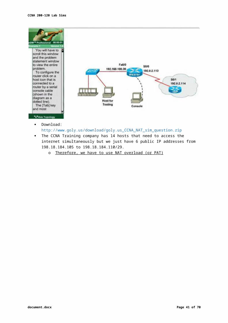
CCNA 200-120 Lab Sims
Hotspot Frame-relay
This question was a multi-choice question; Cisco upgraded it into a lab-sim question.
Instead of listing all the configuration as above, you have to type show frame-relay map and show running-config to get its configuration.
document.docx Page 41 of 53
Exact QOr other servers
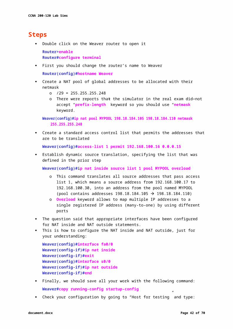
CCNA 200-120 Lab Sims
Question 1 What destination Layer 2 address will be used in the frame header containing a packet
for host 172.30.0.4?A. 704B. 196
C. 702 show frame relay mapD. 344
Question 2 A static map to the S-AMER location is required. Which command should be used to
create this map?
A. frame-relay map ip 172.30.0.3 704 broadcastB. frame-relay map ip 172.30.0.3 196 broadcast from show frame relay mapC. frame-relay map ip 172.30.0.3 702 broadcastD. frame-relay map ip 172.30.0.3 344 broadcast
Question 3 Which connection uses the default encapsulation for serial interfaces on Cisco
routers?
A. The serial connection to the MidEast branch office from show runB. The serial connection to the DeepSouth branch officeC. The serial connection to the NorthCentral branch officeD. The serial connection to the Multinational Core
Question 4 If required, what password should be configured on the router in the MidEast branch
office to allow a connection to be established with the Dubai router?
A. No password is required
B. EnableC. Scr
D. TelnetE. Console
Answer: A or D (as maybe there are 2 versions of this question, depending on the output of “show running-config” command, please read the explanation below)
This question is not clear for a long time but now maybe the trick was solved. What Cisco wants is the word used as password, not the type of connection ,
o In the exam you may see strange words for answers like “En8ble”, “T1net”, “C0nsole”.
All you have to do is to use “Dubai#show running-config” to find the answer.
Comments Q4: if password required which?
o in my example it was connection to Norte! How to figure out which pw is required?
o Dubai#show running-config Check the interface to the router you need connection to. If there is “ppp authentication” you need a password! You will find the password on the top of your running-config output Check the area:
username North password c0nsole username xxxxx yyyyy username…
o In some exercises seen the password was “c0nsole”: o in your case it could be “no password needed” or a different password
document.docx Page 42 of 53
C
B
A
A or D

CCNA 200-120 Lab Sims
Configuration SIM To configure the router (R2-RC) click on the console host icon that is connected to a router by
a serial console cable (shown in the diagram as a dashed black line)
CCNA Training Company recently installed a new router in their office. Complete the network installation by performing the initial router configurations and configuring RIPV2 routing using the router command line interface (CLI) on the R2-RC.
o Name of the router is R2-RCo Enable-secret password is cisco1o The password to access user EXEC mode using the console is cisco2o The password to allow telnet access to the router is cisco3o IPV4 addresses must be configured as follows:
Router has last assignable host address in each subnet Ethernet: 209.165.202.128/27 Serial: 192.0.2.16/28 Interfaces should be enabled.
o Router protocol is RIP V2
Important Note: In practical examinations, please note the following; the actual information is most important.
1. Name of the router is xxx2. Enable-secret password is xxx3. Password to access user EXEC mode using the console is xxx4. The password to allow telnet access to the router is xxx5. IP information
Download: http://www.goly.us/download/goly.us_CCNA_RIP_Configuration.zip
StepsName the router
Router>enableRouter#configure terminalRouter(config)#hostname R2-RC
Set secret passwordR2-RC(config)# enable secret Sec@ret
Set password for the consoleR2-RC(config)#line console 0R2-RC(config-line)#password Sec@ret2R2-RC(config-line)#loginR2-RC(config-line)#exit
Set the Telnet password
document.docx Page 43 of 53

CCNA 200-120 Lab Sims
R2-RC(config)#line vty 0 4R2-RC(config-line)#password Sec@ret3R2-RC(config-line)#loginR2-RC(config-line)#exit
Assign IP address for Ethernet interface (Fa0/0) The Ethernet network 213.123.20.128/27 has:
o Increment:32 (/27 = 255.255.255.224 or 1111 1111.1111 1111.1111 1111.1110 0000)o Network address: 213.123.20.128o Broadcast address: 213.123.20.159 (because 128 + 32 – 1 = 159)
Therefore, the last assignable host address in this subnet is 213.123.20.158 and we will assign it to Fa0/0 interface with these commands:
R2-RC(config)# interface fa0/0R2-RC(config-if)#ip address 213.123.20.158 255.255.255.224R2-RC(config-if)#no shutdownR2-RC(config-if)#exit
Assign IP address for Serial interface (S0/0) Serial network 200.0.1.16/28 has:
Increment:16 (/28 = 255.255.255.240 or 1111 1111.1111 1111.1111 1111.1111 0000) Network address: 200.0.1.16 Broadcast address: 200.0.1.31 (because 16 + 16 – 1 = 31)
So the last assignable host address in this subnet is 200.0.1.30. Finally, we assign it to s0/0/0 interface:
R2-RC(config)# interface s0/0/0R2-RC(config-if)#ip address 200.0.1.30 255.255.255.240R2-RC(config-if)#no shutdownR2-RC(config-if)#exit
Configure RIP v2 routing protocolR2-RC(config)#router ripR2-RC(config-router)#version 2R2-RC(config-router)#network 213.123.20.0R2-RC(config-router)#network 200.0.1.0R2-RC(config-router)#endR2-RC#copy running-config startup-config
Note: We should use classful networks (213.123.20.0 & 200.0.1.0) when configuring RIP. If we use detailed networks (213.123.20.128 & 200.0.1.16) the router will automatically
convert them into classful networks.
Comments General note for anyone taking the exam over the next few weeks:
Learn all sims by heart! I had the same 4 sims except for one question, where the only difference was that packets from R1 to R5 took both R2 and R3 paths instead of only the R2 path.
This exercise: All I had to do is issue show ip route on R1.
document.docx Page 44 of 53

CCNA 200-120 Lab Sims
Implementation SimInstructions
This topology contains 3 routers and 1 switch: complete the topology. Drag the appropriate device icons to the labelled Device Drag the appropriate connections to the locations labelled Connections. Drag the appropriate IP addresses to the locations labelled IP address
o Hint: use the given host addresses and Main router information To remove a device or connection, drag it away from the topology. Use information gathered from the Main router to complete the configuration of any additional
routers. o No passwords are required to access the Main router. o The config terminal command has been disabled for the HQ router. o The router does not require any configuration.
Configuration Configure each additional router with the following:
o Configure the interfaces with the correct IP address and enable the interfaces.o Set the password to allow console access to consolepwo Set the password to allow telnet access to telnetpwo Set the password to allow privilege mode access to privpw
Note: As routes are not being added to the configurations, you will not be able to ping through the internetwork.
All devices have cable autosensing capabilities disabled. All hosts are PC’s
Download: http://www.goly.us/download/goly.us_CCNA_Implementation_question.zip
document.docx Page 45 of 53
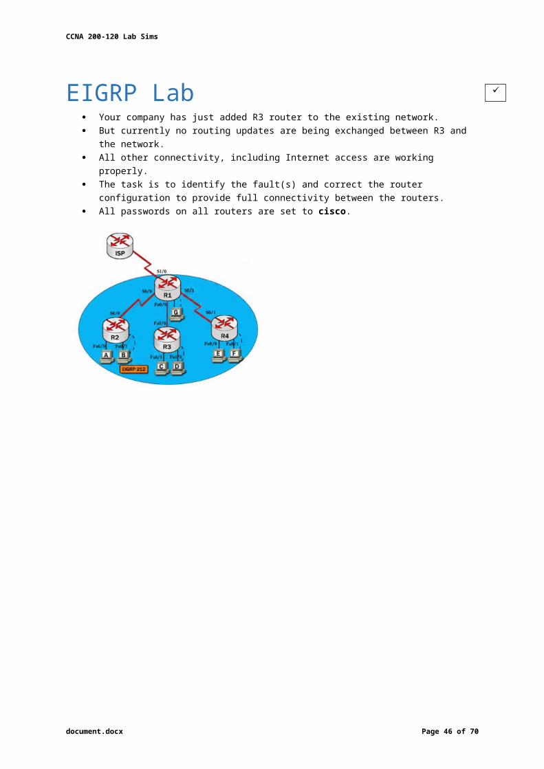
CCNA 200-120 Lab Sims
Implementation Specify appropriate devices and drag them on the “Device” boxes For the device at the bottom-right box, we notice that it has 2 interfaces Fa0/2 and Fa0/4;
moreover, the link connects the PC on the right with the device on the bottom-right is a straight-through link it is a switch
The question stated that this topology contains 3 routers and 1 switch the two other devices are routers
Place them at appropriate locations as follows:
Hosts D and host E will be automatically added after placing two routers. Click on these hosts to gain console access to the neighbouring routers
Specify connections between these devices The router on the left is connected to the Main router through FastEthernet interfaces
o use a crossover cable The router on the right is connected to the Main router through Serial interfaces
o use a serial cable The router on the right and the Switch
o use a straight-through cable The router on the left and the computer
o use a crossover cable
To remember which type of cable you should use, follow these tips:o To connect two serial interfaces of 2 routers we use serial cableo To specify when we use crossover cable or straight-through cable, we should
remember:– Group 1: Router, Host, Server– Group 2: Hub, Switch– One device in group 1 + One device in group 2: use straight-through cable– Two devices in the same group: use crossover cable
o Straight-through cables connect switch to router, switch to host, hub to host, hub to server…
o Crossover cables are used to connect switch to switch, switch to hub, router to router, host to host…
document.docx Page 46 of 53
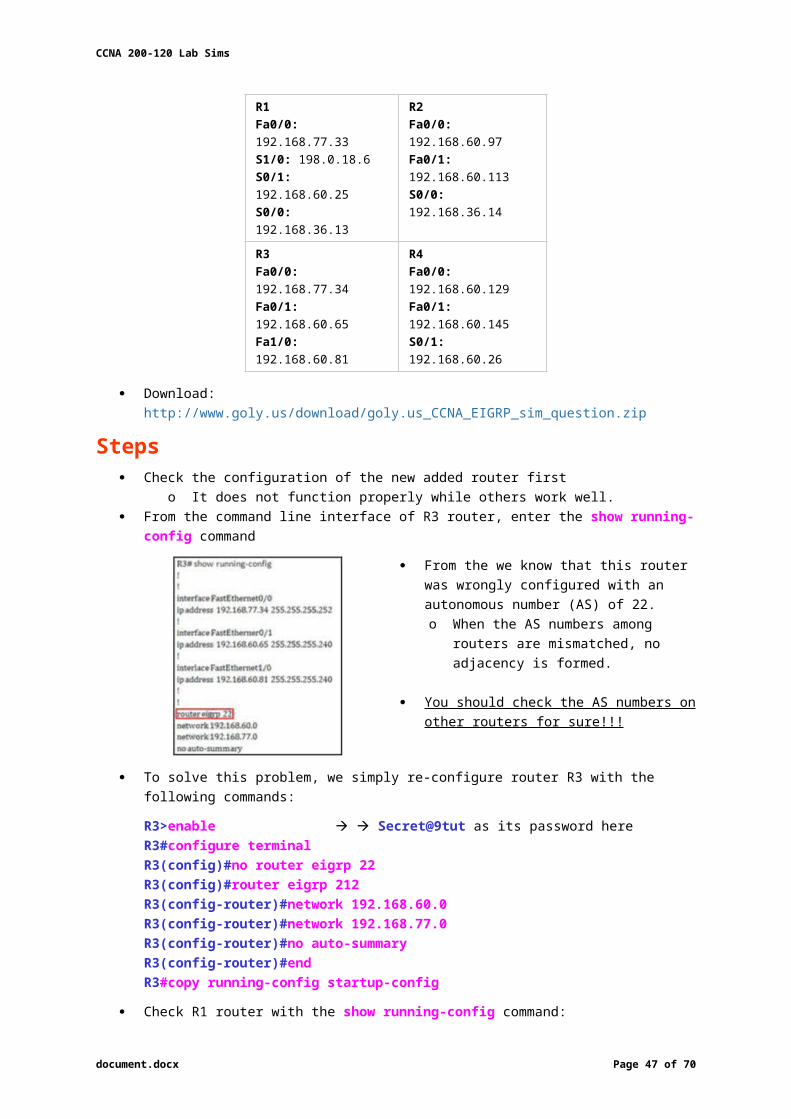
CCNA 200-120 Lab Sims
Assign appropriate IP addresses for interfaces From Main router, use the show running-config command:
Notice that you may see different IP addresses in the real CCNA exam, the ones shown above are just used for demonstration
From the output we learned that the ip address of Fa0/0 interface of the Main router is 192.168.152.177/28. This address belongs to a subnetwork which has:
o Increment: 16 (/28 = 255.255.255.240)o Network address: 192.168.152.176 (because 176 = 16 * 11 and 176 < 177)o Broadcast address: 192.168.152.191 (because 191 = 176 + 16 – 1)
And we can pick up an ip address from the list that belongs to this subnetwork: 192.168.152.190 and assign it to the Fa0/0 interface the router on the left
Use the same method for interface Serial0/0 with an ip address of 192.168.152.161
o Increment: 16o Network address: 192.168.152.160 (because 160 = 16 * 10 and 160 < 161)o Broadcast address: 192.168.152.175 (because 176 = 160 + 16 – 1)
And we choose 192.168.152.174 for Serial0/0 interface of the router on the right
Interface Fa0/1 of the router on the left IP (of the computer on the left): 192.168.152.129/28
o Increment: 16o Network address: 192.168.152.128 (because 128 = 16 * 8 and 128 < 129)o Broadcast address: 192.168.152.143 (because 143 = 128 + 16 – 1)
Choose 192.168.152.142 from the list
document.docx Page 47 of 53

CCNA 200-120 Lab Sims
Interface Fa0/0 of the router on the right IP (of the computer on the left): 192.168.152.225/28
o Increment: 16o Network address: 192.168.152.224 (because 224 = 16 * 14 and 224 < 225)o Broadcast address: 192.168.152.239 (because 239 = 224 + 16 – 1)
Choose 192.168.152.238 from the list
Summary
Configure two routers on the left and right: Assign appropriate IP addresses to Fa0/0 & Fa0/1 interfaces (note Router 1 = left router):
Router1>enableRouter1#configure terminalRouter1(config)#interface fa0/0Router1(config-if)#ip address 192.168.152.190 255.255.255.240Router1(config-if)#no shutdownRouter1(config-if)#interface fa0/1Router1(config-if)#ip address 192.168.152.142 255.255.255.240Router1(config-if)#no shutdown
Router2>enableRouter2#configure terminalRouter2(config)#interface fa0/0Router2(config-if)#ip address 192.168.152.238 255.255.255.240Router2(config-if)#no shutdownRouter2(config-if)#interface serial0/0Router2(config-if)#ip address 192.168.152.174 255.255.255.240Router2(config-if)#no shutdown
document.docx Page 48 of 53
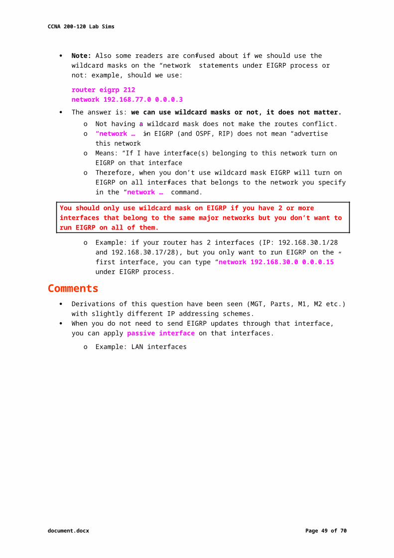
CCNA 200-120 Lab Sims
Set passwords Console password (R1 and R2):
Router1(config-if)#exitRouter1(config)#line console 0Router1(config-line)#password consolepwRouter1(config-line)#loginRouter1(config-line)#exit
Router2(config-if)#exitRouter2(config)#line console 0Router2(config-line)#password consolepwRouter2(config-line)#loginRouter2(config-line)#exit
Telnet password (R1 and R2):Router1(config)#line vty 0 4Router1(config-line)#password telnetpwRouter1(config-line)#loginRouter1(config-line)#exit
Router2(config)#line vty 0 4Router2(config-line)#password telnetpwRouter2(config-line)#loginRouter2(config-line)#exit
Privilege mode password (R1 and R2):Router1(config)#enable password privpw Router1(config)#enable password privpw
Remember to save the configuration when you are finished Save the configuration (R1 and R2):
Router1(config)#exitRouter1#copy running-config startup-config
Router2(config)#exitRouter2#copy running-config startup-config
document.docx Page 49 of 53
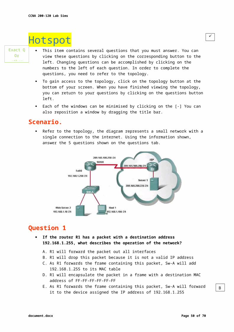
CCNA 200-120 Lab Sims
Drag and Drop Sim You have been hired by Specialty Hardware Incorporated to document the layout of the
network. Complete the following tasks:
o Complete the network topology shown in the graphic by dragging the labels below with the appropriate router types, interface types, and IP addresses to the graphic.
o Find the information you need by using the router console attached to the R-CENTER router.
Download: http://www.goly.us/download/goly.us_CCNA_drag_and_drop_sim_question.pkt
This is the simplest lab question in four labs you see in the real CCNA exam.
Step 1: Identify Types of Router We should identify the types of these routers by using the show cdp neighbors command:
There are 3 columns we should pay more attention to:
o Local Interface: the interface on the device you are using “show cdp neighbors” command. In this case it is the interface of R-CENTER router
o Platform: the platform of neighbour deviceo Port ID: the neighbour device’s port or interface on which the CDP packets are
multicast
Step 2: Router Placement From the exhibit, the “Local Interface”, “Platform” and “Port ID” columns, we can identify
where these four routers should be placed and their corresponding associated ports
document.docx Page 50 of 53

CCNA 200-120 Lab Sims
Step 3: IP Addresses Use show running-config to find out the ip addresses of four interfaces on R-CENTER
You can easily assign corresponding ip addresses to four neighbour routers, which are on the same network with R-CENTER router’s interfaces
Please remember in the real CCNA Exam the routers’ types, ip addresses and interfaces may be different! So make sure you understand how it works.
Comments
document.docx Page 51 of 53
CCNA 200-120 Lab Sims
DHCP Group of Four Questions In the real exam you will be taken to a LAB simulation environment but it is, in fact, just
a group of 4 multi-choice questions!
Refer to the exhibit.
Using the information shown, answer the questions
Question 1 All hosts in the networks have been operational for several hours when the DHCP server
goes down. What happens to the hosts that have obtained service from the DHCP server?
A. The hosts will not be able to communicate with any other hosts.B. The hosts will continue to communicate normally for a period of time.C. The hosts will be able to communicate with hosts outsides their own networkD. The hosts will only be able to communicate with other hosts by IP address not by
hostname
DHCP uses dynamic allocation mechanism to save IP addresses, o Which assigns an IP address to a client for a limited period of time.
When DHCP servers goes down, clients can still use their allocated IP address for a period of time.
Question 2 What is the purpose of the DHCP server?
A. to provide storage for emailB. to translate URLs to IP addressesC. to translate IPv4 addresses to MAC addressesD. to provide an IP configuration information to hosts
The main purpose of the DHCP server is to provide IP configuration parameters to hosts such as the default gateway, domain name, Domain Name System (DNS) server…
Question 3 How is the message sent from a PC2 when is first powers on and attempts to contact the
DHCP Server?
A. Layer 3 unicastB. Layer 3 broadcast
C. Layer 3 multicastD. Without any Layer 3 encapsulation
When a client boots up for the first time, it transmits a DHCPDISCOVER message on its local physical subnet.
As the client has no way of knowing the subnet to which it belongs, the DHCPDISCOVER is an all-subnets broadcast
o Destination IP address of 255.255.255.255, which is a layer 3 broadcast address . The client does not have a configured IP address, so the source IP address of 0.0.0.0 is used.
document.docx Page 52 of 53
B
D
B
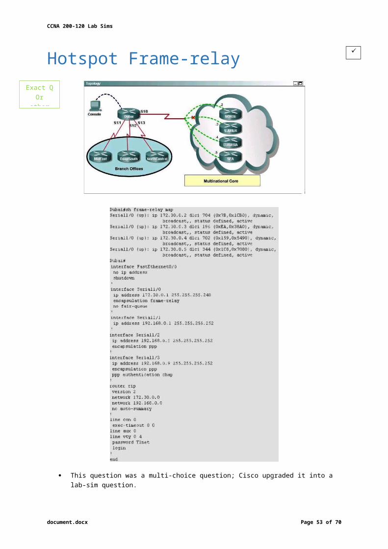
CCNA 200-120 Lab Sims
Question 4 What is the default behaviour of R1 when PC1 requests service from DHCP server?
A. Drop the requestB. Broadcast the request to R2 and R3
C. Forward the request to R2D. Broadcast the request to R2, R3 and ISP
When PC1 requests service from DHCP server (for example, it requests an IP address), it sends a broadcast packet.
But R1 router, by default, will not forward broadcast packet and drop it .
If you want to use the DHCP server from another network (like in this case) you can use the ip helper-address command on a network interface which will make the router forward these DHCP - UDP broadcasts.
document.docx Page 53 of 53
A


![Ccna lab manual[1]](https://static.fdocuments.us/doc/165x107/541276cb7bef0ad8528b547f/ccna-lab-manual1.jpg)