restep.stryker - Stryker Sustainability...
32
Deep Vein Thrombosis (DVT) System User Manual
Transcript of restep.stryker - Stryker Sustainability...
Deep Vein Thrombosis (DVT) System
User ManualMANUFACTURED FOR
1810 West Drake DriveTempe, Arizona, 85283
888.888.3433
restep.stryker.com
RM801005J Printed in the USA
RM801005 Restep Pump Manual Cover.indd 1 1/19/17 2:54 PM

Restep—an economical
and INNOVATIVE solution for
today’s HEALTHY Hospital.
“ “ The information presented in this brochure is intended to demonstrate a Stryker product. Always refer to the package insert, product label and/or user instructions before using any Stryker product. Products may not be available in all markets. Product availability is subject to the regulatory or medical practices that govern individual markets. Please contact your Stryker representative if you have questions about the availability of Stryker products in your area.
Stryker Corporation or its divisions or other corporate affiliated entities own, use or have applied for the following trademarks or service marks: Restep®. All other trademarks are trademarks of their respective owners or holders.
RM801005 Restep Pump Manual Cover.indd 2 1/19/17 2:54 PM

1
TABLE OF CONTENTS
INTRODUCTION ......................................................................................................................... 2 Clinical Indication for use ........................................................................................................ 2 Contraindications ................................................................................................................... 2 Precautions ........................................................................................................................... 3
GENERAL................................................................................................................................... 3 Symbols ............................................................................................................................... 3 Notes, Cautions, and Warning statements ............................................................................... 4 EMC Warning......................................................................................................................... 4 Hazard Information ................................................................................................................ 4
SYSTEM COMPONENTS ............................................................................................................ 5 Pump Kit/Accessories ........................................................................................................... 5 Garments .............................................................................................................................. 6
SYSTEM INSTALLATION ............................................................................................................ 7 Battery Installation ................................................................................................................. 7 Charging the Battery .............................................................................................................. 7 Using the Bed Bracket ........................................................................................................... 8
GARMENT USE .......................................................................................................................... 9 Calf Garments ....................................................................................................................... 9 Bariatric Calf Garments ........................................................................................................ 10 Thigh Garments ................................................................................................................... 10 Foot Garments .................................................................................................................... 11
SYSTEM CONTROLS ...............................................................................................................11 Front Control Panel ..........................................................................................................11-12
PUMP OPERATION ..................................................................................................................13 Switching the pump on and off ............................................................................................. 13 Garment TYPE selection ....................................................................................................... 13 Garment MODE selection ..................................................................................................... 14 Mute ................................................................................................................................... 14
WARNINGS AND ALARMS .......................................................................................................14 HIGH PRESSURE .................................................................................................................. 14 LOW PRESSURE .................................................................................................................. 14 CRITICAL LOW BATTERY ....................................................................................................... 15 BAD BATTERY ..................................................................................................................... 15
TROUBLESHOOTING ...............................................................................................................16CLEANING ...............................................................................................................................17PREVENTIVE MAINTENANCE ..................................................................................................18HANDLING AND STORAGE ......................................................................................................22RETURNS ................................................................................................................................22SPECIFICATIONS .....................................................................................................................23EMC GUIDANCE AND DECLARATIONS ...............................................................................24-27

2
INTRODUCTIONThis manual should be used for the initial set up of the Restep® system and for reference purposes.
Clinical Indications for use
The primary application of the Restep® system is for the prevention of Deep Vein Thrombosis (DVT) due to the presence of risk factors for thrombus formation during orthopedic, trauma, neurology, urologic, critical care, general medicine, obstetrics, and general surgery.
� This system should be used when prescribed by a physician.
� Garments should be removed regularly to inspect the skin.
� Patients with diabetes or vascular disease require frequent skin assessment.
� When appropriate, patients should be instructed in the proper use of the system and any problems should be reported to the nursing staff.
� The garments should be applied to the patient prior to the induction of anesthesia.
� If the garment cannot be applied to the operative limb during surgery, it may be applied to the limb once the patient reaches the recovery room. For a non-surgical patient, the system should be applied as soon as the risk of DVT is identified.
� The system should be used continuously until the person is fully ambulatory. The therapy can continue with leg garments for people with limited mobility.
Contraindications
The Restep® system should NOT be used in the following conditions:
� Severe arteriosclerosis or active infection.
� Suspected or known acute DVT.
� Severe congestive heart failure or any condition where increased fluid to the heart may be detrimental.
� Existing pulmonary edema.
� Local skin or tissue conditions in which the garments would interfere.
If in doubt, refer to the patient’s physician before using device.
CAUTION: US Federal law restricts this device to sale by or on the order of a physician.
Precautions
� Do not drop the power adapter or pump as it may result in damage to the components potentially affecting functional performance.
� Remove pump and Bed Bracket (RSP166) if applicable from the footboard or bedrail prior to moving the bed to prevent impact damage during transportation.

3
� Do not lean on the pump when it is hanging from the footboard or bedrail as this may result in a fracture of the bracket housing.
� Place the equipment in a location where it will not be susceptible to impact forces from other equipment or personnel.
� Pump hooks are designed for bed attachment only.
� It is not recommended that pumps or Bed Brackets (RSP166) if applicable are permanently fastened or tied to objects.
� Only the pump and garment combinations provided by Stryker Sustainability Solutions should be used. The correct function of the product cannot be guaranteed if the incorrect pump/garment combinations are used.
� Regularly check the system while in use, assuring pump operation and garment fit.
� Keep the pump away from sources of liquids and do not immerse in water.
� Switch off the electrical supply to the pump by removing the power supply from the power outlet and the pump before cleaning and inspection.
� Do not use cleaning solutions that are known to damage plastics.
� Do not autoclave any parts of the system.
� Ensure the system is clean and dry prior to storage.
GENERALThe Restep® system has been tested and certified for the following standards:
UL 60601-1 CAN/CSA C22.2 No. 601.1 EN 60601-1 IEC 60601-1 IEC 60601-1-2
The power adapter has been tested by the manufacturer and certified for the following standards:
UL 60601-1 CAN/CSA C22.2 No. 601.1 EN 60601-1
Symbols
Symbols used on this product are as below:
Read through all instructions before use.
� NOTES Indicates some tips or some information users should be aware of.
Caution & Warning statements
� CAUTION Indicates correct operation or maintenance procedures to prevent damage to or destruction of the equipment or other property.
� WARNING Calls attention to a potential hazard that requires correct procedures or practices in order to prevent personal injury.
Type BF
Class II equipment
Consult instructions for use
Single patient use only, do not reuse
Manufacturer
REF Part Number
Serial Number
Stryker Sustainability SolutionsTempe, AZ
℞ONLY CAUTION: US Federal Law restricts this device to sale by or on the order of a physician
4
EMC Warning
This product complies with the requirements of applicable EMC standards. The use of accessories not specified by the manufacturer may result in increased emissions by, or decreased immunity of the equipment, affecting its performance.
There is a possibility of electromagnetic interference with other devices. When there is suspicion of possible EMC interference to the pump, it is recommended to shut down the electrical devices nearby, one-by-one, to locate the possible interference source.
Consult an expert if you are not sure how to solve the interference problem.
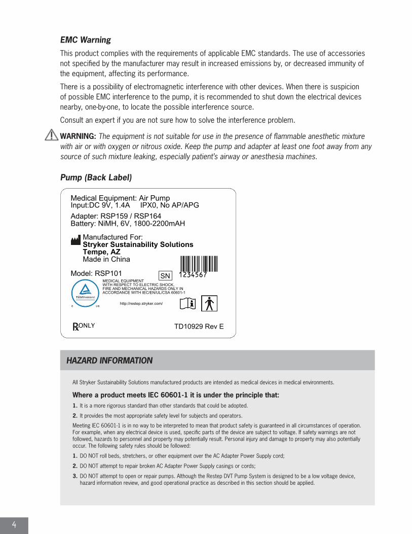
WARNING: The equipment is not suitable for use in the presence of flammable anesthetic mixture with air or with oxygen or nitrous oxide. Keep the pump and adapter at least one foot away from any source of such mixture leaking, especially patient’s airway or anesthesia machines.
HAZARD INFORMATION
All Stryker Sustainability Solutions manufactured products are intended as medical devices in medical environments.
Where a product meets IEC 60601-1 it is under the principle that:1. It is a more rigorous standard than other standards that could be adopted.
2. It provides the most appropriate safety level for subjects and operators.
Meeting IEC 60601-1 is in no way to be interpreted to mean that product safety is guaranteed in all circumstances of operation. For example, when any electrical device is used, specific parts of the device are subject to voltage. If safety warnings are not followed, hazards to personnel and property may potentially result. Personal injury and damage to property may also potentially occur. The following safety rules should be followed:
1. DO NOT roll beds, stretchers, or other equipment over the AC Adapter Power Supply cord;
2. DO NOT attempt to repair broken AC Adapter Power Supply casings or cords;
3. DO NOT attempt to open or repair pumps. Although the Restep DVT Pump System is designed to be a low voltage device, hazard information review, and good operational practice as described in this section should be applied.
Stryker Sustainability SolutionsTempe, AZ
℞ONLY
Pump (Back Label)
5
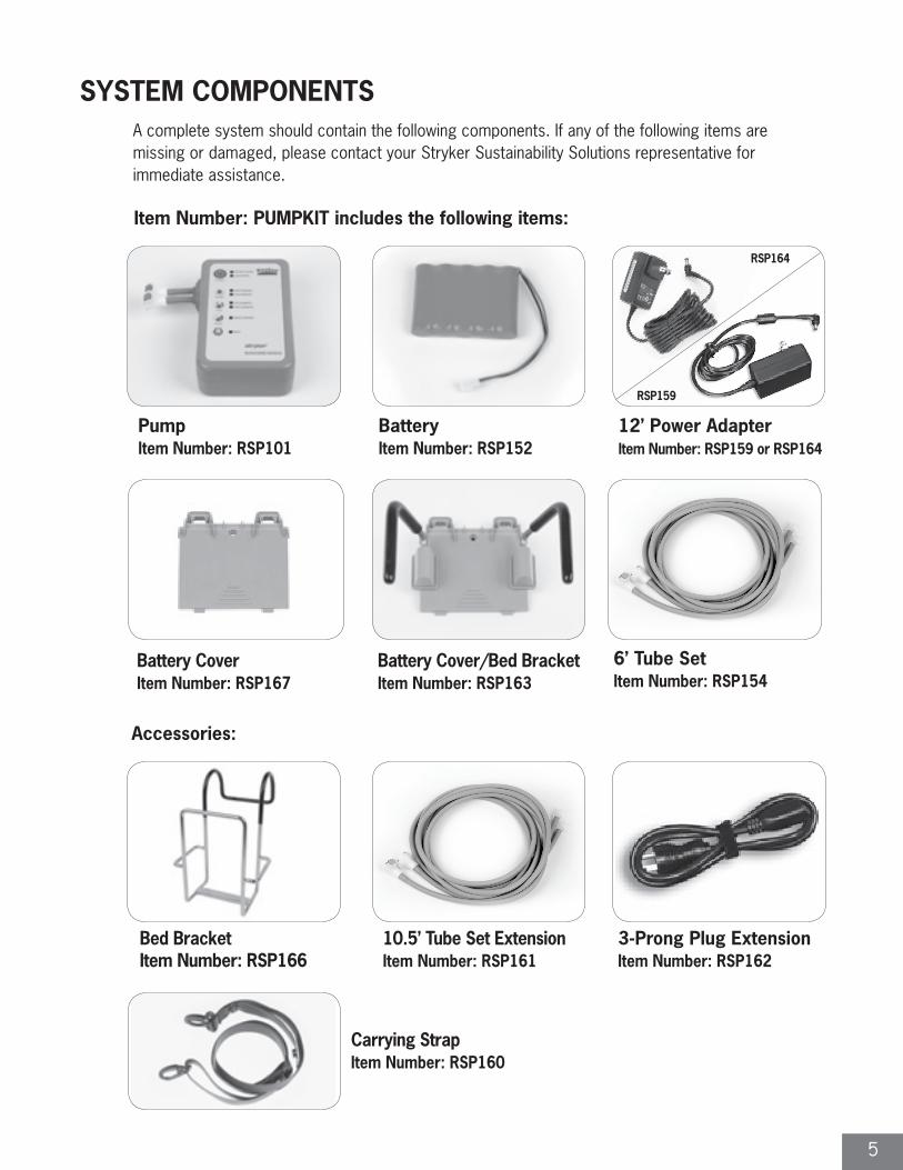
SYSTEM COMPONENTSA complete system should contain the following components. If any of the following items are missing or damaged, please contact your Stryker Sustainability Solutions representative for immediate assistance.
Pump Item Number: RSP101
10.5’ Tube Set ExtensionItem Number: RSP161
Bed BracketItem Number: RSP166
3-Prong Plug ExtensionItem Number: RSP162
Battery Cover/Bed BracketItem Number: RSP163
Battery CoverItem Number: RSP167
Carrying StrapItem Number: RSP160
6’ Tube SetItem Number: RSP154
Battery Item Number: RSP152
12’ Power Adapter Item Number: RSP159 or RSP164
Item Number: PUMPKIT includes the following items:
Accessories:
RSP164
RSP159
6
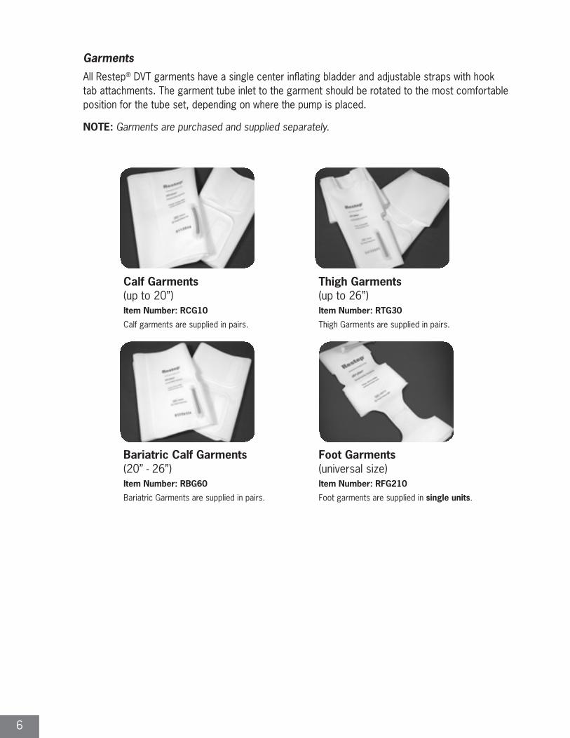
Garments All Restep® DVT garments have a single center inflating bladder and adjustable straps with hook tab attachments. The garment tube inlet to the garment should be rotated to the most comfortable position for the tube set, depending on where the pump is placed.
NOTE: Garments are purchased and supplied separately.
Calf Garments (up to 20”) Item Number: RCG10
Calf garments are supplied in pairs.
Thigh Garments (up to 26”)Item Number: RTG30
Thigh Garments are supplied in pairs.
Bariatric Calf Garments (20” - 26”)Item Number: RBG60
Bariatric Garments are supplied in pairs.
Foot Garments (universal size)Item Number: RFG210
Foot garments are supplied in single units.
7
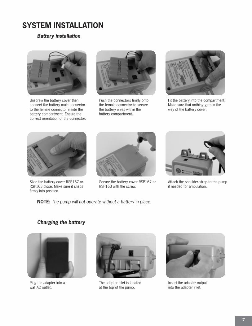
SYSTEM INSTALLATIONBattery installation
Unscrew the battery cover then connect the battery male connector to the female connector inside the battery compartment. Ensure the correct orientation of the connector.
Push the connectors firmly onto the female connector to secure the battery wires within the battery compartment.
Fit the battery into the compartment. Make sure that nothing gets in the way of the battery cover.
Slide the battery cover RSP167 or RSP163 close. Make sure it snaps firmly into position.
Secure the battery cover RSP167 or RSP163 with the screw.
Attach the shoulder strap to the pump if needed for ambulation.
NOTE: The pump will not operate without a battery in place.
Charging the battery
Plug the adapter into a wall AC outlet.
The adapter inlet is located at the top of the pump.
Insert the adapter output into the adapter inlet.
8
Charging the battery (continued)
NOTE: • In a nominal battery, charging may take 16-48 hours (the system may be used while recharging); discharging a fully charged nominal battery (via battery-only operation) may take 8 hours. Overall battery life/effectiveness is maintained by continuous full charging and discharging cycling routines.
• Charge the battery when the battery capacity is low. This will be indicated when the red LOW BATTERY light is solid accompanied by a constant audible alarm when the pump is under battery-only operations.
• While charging the battery, the BATTERY CHARGE light (green) will be blinking. When the battery is fully charged, an audible double-beep is presented once, and the BATTERY CHARGE light (green) will be lit constantly.
• While pump is not being used and idle the power adapter should be connected to the pump to insure a charged battery during its next use. If the pump was left idle without being charged, it is recommended that the pump be charged until the BATTERY CHARGE light emits a constant green light prior to utilization without a power adapter.
• It is normal for the battery to get warm during charging and while in use.
CAUTION:
• Use only the provided manufacturer approved battery included in the package. Replacement Item Number: RSP152.
• Disconnect the adapter from the pump before unplugging the adapter from the AC outlet. Disconnection in reverse order may cause damage to the pump.
• Use only the provided manufacturer approved power adapter included in the package. DO NOT USE any other power adapters with the Restep® system. Replacement Item Number: RSP164.
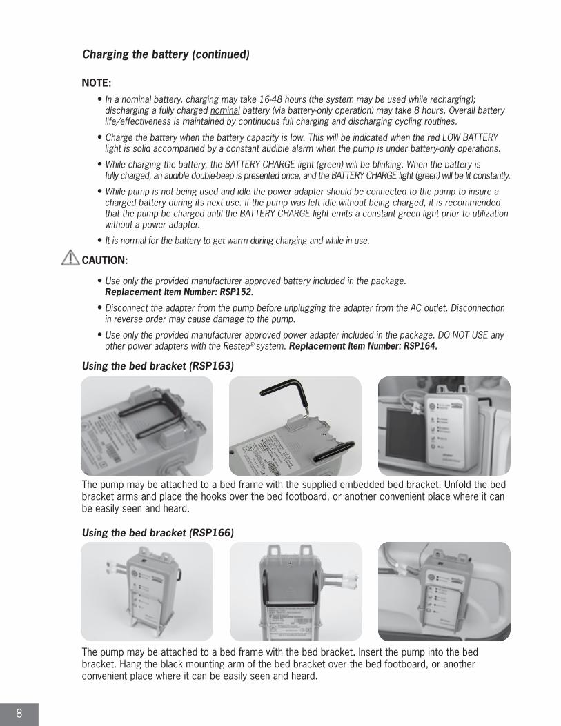
Using the bed bracket (RSP163)
The pump may be attached to a bed frame with the supplied embedded bed bracket. Unfold the bed bracket arms and place the hooks over the bed footboard, or another convenient place where it can be easily seen and heard.
Using the bed bracket (RSP166)
The pump may be attached to a bed frame with the bed bracket. Insert the pump into the bed bracket. Hang the black mounting arm of the bed bracket over the bed footboard, or another convenient place where it can be easily seen and heard.
9
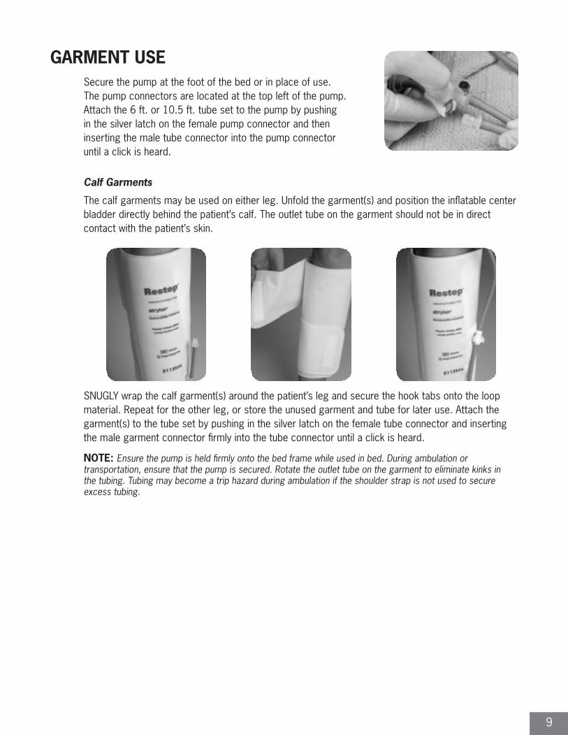
GARMENT USESecure the pump at the foot of the bed or in place of use. The pump connectors are located at the top left of the pump. Attach the 6 ft. or 10.5 ft. tube set to the pump by pushing in the silver latch on the female pump connector and then inserting the male tube connector into the pump connector until a click is heard.
Calf Garments
The calf garments may be used on either leg. Unfold the garment(s) and position the inflatable center bladder directly behind the patient’s calf. The outlet tube on the garment should not be in direct contact with the patient’s skin.
SNUGLY wrap the calf garment(s) around the patient’s leg and secure the hook tabs onto the loop material. Repeat for the other leg, or store the unused garment and tube for later use. Attach the garment(s) to the tube set by pushing in the silver latch on the female tube connector and inserting the male garment connector firmly into the tube connector until a click is heard.
NOTE: Ensure the pump is held firmly onto the bed frame while used in bed. During ambulation or transportation, ensure that the pump is secured. Rotate the outlet tube on the garment to eliminate kinks in the tubing. Tubing may become a trip hazard during ambulation if the shoulder strap is not used to secure excess tubing.
10
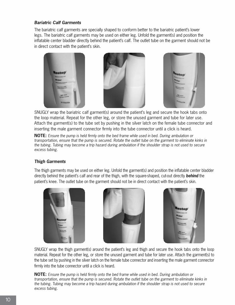
Bariatric Calf Garments
The bariatric calf garments are specially shaped to conform better to the bariatric patient’s lower legs. The bariatric calf garments may be used on either leg. Unfold the garment(s) and position the inflatable center bladder directly behind the patient’s calf. The outlet tube on the garment should not be in direct contact with the patient’s skin.
SNUGLY wrap the bariatric calf garment(s) around the patient’s leg and secure the hook tabs onto the loop material. Repeat for the other leg, or store the unused garment and tube for later use. Attach the garment(s) to the tube set by pushing in the silver latch on the female tube connector and inserting the male garment connector firmly into the tube connector until a click is heard.
NOTE: Ensure the pump is held firmly onto the bed frame while used in bed. During ambulation or transportation, ensure that the pump is secured. Rotate the outlet tube on the garment to eliminate kinks in the tubing. Tubing may become a trip hazard during ambulation if the shoulder strap is not used to secure excess tubing.
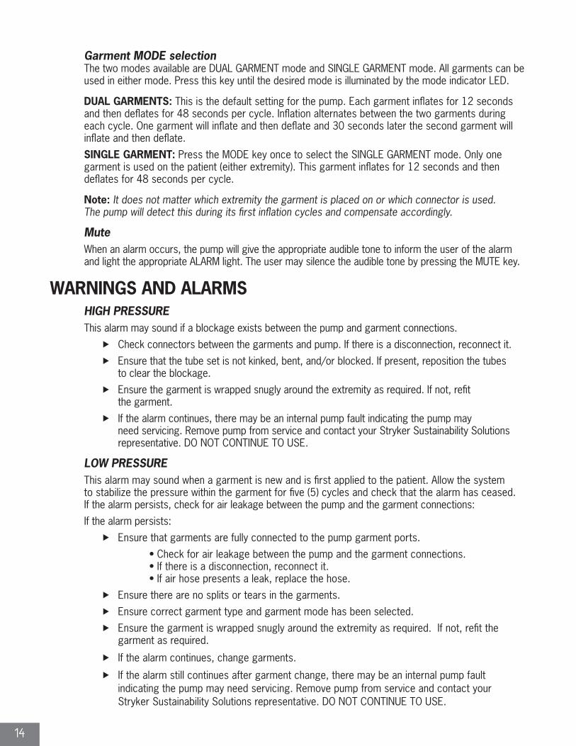
Thigh Garments
The thigh garments may be used on either leg. Unfold the garment(s) and position the inflatable center bladder directly behind the patient’s calf and rear of the thigh, with the square-shaped, cut-out directly behind the patient’s knee. The outlet tube on the garment should not be in direct contact with the patient’s skin.
SNUGLY wrap the thigh garment(s) around the patient’s leg and thigh and secure the hook tabs onto the loop material. Repeat for the other leg, or store the unused garment and tube for later use. Attach the garment(s) to the tube set by pushing in the silver latch on the female tube connector and inserting the male garment connector firmly into the tube connector until a click is heard.
NOTE: Ensure the pump is held firmly onto the bed frame while used in bed. During ambulation or transportation, ensure that the pump is secured. Rotate the outlet tube on the garment to eliminate kinks in the tubing. Tubing may become a trip hazard during ambulation if the shoulder strap is not used to secure excess tubing.

11
Foot Garments
The foot garments may be used on either foot. Unfold the garment(s) and position the inflatable center bladder directly below the arch of the patient’s foot. The outlet tube should be adjusted so it is parallel with the patient’s toes.
NOTE: Do not use calf garments and foot garments on the same patient at the same time.
Snugly wrap the garment(s) around the patient’s foot and secure the hook tabs. Wrap the ankle straps around the back of the ankle and on top of the foot. Repeat for the other foot, or store the unused garment and tube for later use. Attach the garment(s) to the tube set by pushing in the silver latch on the female tube connector and inserting the male garment connector firmly into the tube connector until a click is heard.
NOTE:
• Foot garments should be removed prior to patient ambulation or transportation. • See online IFU for full details: http://restep.stryker.com
SYSTEM CONTROLS
Front control panel
The functions of the Restep® system pump are described below.
1. Power Switch2. Alarm Graphic3. Garment Type Selection Key4. Mode Selection Key5. Mute Key6. Battery Status Indication7. Alarm Indication, HIGH/LOW Pressure8. Garment Type Indication9. Mode Indication10. Alarm/Mute Indication
1 6
2 7
3 8
4 9
5 10

12
1. Power Switch Press the Power Switch to turn the power ON/OFF, and to start/stop the pump.
2. Alarm Graphic This is NOT a key. This graphic highlights the function of the HIGH/LOW pressure alarm indicators.
3. Garment Type Selection Key TYPE selection key is inactivated after 60 seconds of initially powering on the pump. Press the TYPE key to select either LEG GARMENTS (default) or FOOT GARMENTS.
4. Mode Selection Key MODE selection key is inactivated after 60 seconds of initially powering on the pump. Press the MODE key to select dual garment (default) or SINGLE GARMENT.
5. Mute Key Press the Mute Key to silence the audible alarm. If the mute key is enabled (alarm silenced) it will disable (alarm reactivated) automatically after 3 minutes.
6. Battery Status Indication � BATTERY CHARGE light (solid green) = battery fully charged state reached
� BATTERY CHARGE light (flashing green) = battery charging
� LOW BATTERY light (solid red) with constant audible alarm, pump has vented and powered down to a suspended/safe mode = low battery/charge required
� LOW BATTERY light (flashing red) no audible alarm = bad battery (cannot reach fully charged state in 48 hours); pump is on suspended mode and requires all power sources to be removed (AC power adapter and battery) in order to reset
7. Alarm Indication► HIGH PRESSURE light (solid red) with beeping audible alarm = garment not deflating
► HIGH PRESSURE light (solid red) with constant audible alarm = high pressure/kinked tubing
► LOW PRESSURE light (solid yellow) with constant audible alarm = no garment
► LOW PRESSURE light (solid yellow) with beeping audible alarm = low pressure
8. Garment Type Indication► LEG GARMENT light = calf, bariatric calf, and thigh garments in use
► FOOT GARMENT light = foot garments in use
► The default setting is LEG garment mode. Press this key to select FOOT garments.
9. Mode Indication The SINGLE GARMENT light is lit when selected for any single garment, including the foot garment.
10. Mute Indication The MUTE light (yellow) is lit when the MUTE mode is enabled. This function will disable after 3 minutes of activation to allow the user to hear future audible alarms.

13
PUMP OPERATIONSwitching the pump on and off
Light Indicators while pump is off
� No light = pump off and not connected to power
� BATTERY CHARGE light (flashing green) = battery charging
� BATTERY CHARGE light (solid green) = battery charged
To start pump operation, press the POWER button once and wait. The pump will undergo a software auto-check for a few seconds. During this time, the LEG GARMENT light may flash. After the auto-check is completed, the LEG GARMENT light will be lit constantly.
NOTE: When the POWER button is pressed, Restep pumps using Software PSoC Version 2.3 will also produce an audible beep and the BATTERY CHARGE and LOW BATTERY lights will flash simultaneously. A label indicating Software PSoC Version 2.3 can be found on the back of the pump if applicable. Please be patient and do not press the POWER button again or you may turn the pump off.
The pump will now begin its normal operation cycle. Allow the pump to run for several cycles to allow the garments to inflate and fit their shape to the patient’s extremity. During this time the “LOW PRESSURE” alarm may activate. If, after a few cycles, this alarm does not reset, please refer to the trouble-shooting guide.
To end pump operation, press POWER button again. When the pump is powered down during an inflation cycle, the Garment TYPE light will flash while the valves open and drain the pressure from the garment. This ensures the system is left in a safe deflated mode for the patient.
NOTE: You may change the TYPE or MODE settings only within the first 60 seconds of the initial Power button press; after 60 seconds, TYPE and MODE selection keys are inactivated. It is NOT recommended to change garments after initial setup while pump is in use. The pump should be turned off during a garment change to avoid unnecessary alarm disturbance to the patient.
Garment TYPE selection
The user may select between the LEG GARMENTS type or FOOT GARMENTS type by pressing the Type Selection Key. Press this key until the desired type is illuminated by the garment type indicator LED.
LEG: This is the default setting for calf, bariatric calf, and/or thigh garments. The operating inflated pressure is 40mmHg and the compression delivered is considered a uniform-type compression. The LEG GARMENT light will flash during initial setup of the pump and then will be lit constantly during use.
FOOT: Select this button for foot garment use. The operating inflated pressure is 80mmHg and the compression delivered is considered a uniform-type compression. The FOOT GARMENT light will be lit constantly when selected.
Note: Ensure the garments on the patient and the garment TYPE selection are the same. Do not mix leg and foot garments on the same patient. If desired, a calf and thigh garment may be used simultaneously.
14
Garment MODE selectionThe two modes available are DUAL GARMENT mode and SINGLE GARMENT mode. All garments can be used in either mode. Press this key until the desired mode is illuminated by the mode indicator LED.
DUAL GARMENTS: This is the default setting for the pump. Each garment inflates for 12 seconds and then deflates for 48 seconds per cycle. Inflation alternates between the two garments during each cycle. One garment will inflate and then deflate and 30 seconds later the second garment will inflate and then deflate.
SINGLE GARMENT: Press the MODE key once to select the SINGLE GARMENT mode. Only one garment is used on the patient (either extremity). This garment inflates for 12 seconds and then deflates for 48 seconds per cycle.
Note: It does not matter which extremity the garment is placed on or which connector is used. The pump will detect this during its first inflation cycles and compensate accordingly.
MuteWhen an alarm occurs, the pump will give the appropriate audible tone to inform the user of the alarm and light the appropriate ALARM light. The user may silence the audible tone by pressing the MUTE key.
WARNINGS AND ALARMSHIGH PRESSUREThis alarm may sound if a blockage exists between the pump and garment connections.
� Check connectors between the garments and pump. If there is a disconnection, reconnect it.
� Ensure that the tube set is not kinked, bent, and/or blocked. If present, reposition the tubes to clear the blockage.
� Ensure the garment is wrapped snugly around the extremity as required. If not, refit the garment.
� If the alarm continues, there may be an internal pump fault indicating the pump may need servicing. Remove pump from service and contact your Stryker Sustainability Solutions representative. DO NOT CONTINUE TO USE.
LOW PRESSURE This alarm may sound when a garment is new and is first applied to the patient. Allow the system to stabilize the pressure within the garment for five (5) cycles and check that the alarm has ceased.
If the alarm persists, check for air leakage between the pump and the garment connections:
If the alarm persists:
� Ensure that garments are fully connected to the pump garment ports.
• Check for air leakage between the pump and the garment connections. • If there is a disconnection, reconnect it. • If air hose presents a leak, replace the hose.
� Ensure there are no splits or tears in the garments.
� Ensure correct garment type and garment mode has been selected.
� Ensure the garment is wrapped snugly around the extremity as required. If not, refit the garment as required.
� If the alarm continues, change garments.
� If the alarm still continues after garment change, there may be an internal pump fault indicating the pump may need servicing. Remove pump from service and contact your Stryker Sustainability Solutions representative. DO NOT CONTINUE TO USE.
15
CRITICAL LOW BATTERYThis alarm will sound during battery-only pump operation when the battery is near depletion. The following actions will be initiated by the pump when this alarm is activated:
� A solid tone, audible alarm will begin and continue for 10 minutes.
� This alarm cannot be disengaged by pressing the MUTE button.
� The garments will be vented immediately
� The pump operations will be suspended for 10 minutes
� If the User connects the AC Adapter Power Supply to the pump within 10 minutes of alarm initiation, the pump will automatically resume operations (POWER button press is not required) and begin charging the battery.
� If the AC Adapter Power Supply is not connected to the pump after 10 minutes of alarm initiation, the pump will completely power off and will not power on until the AC Adapter Power Supply is connected to the pump.
� If the interval between achieving full battery charge to a critical low battery alarm begins to be noticeably shorter over time (battery operation run-time), the battery pack may require a replacement.
� If a new, replacement battery is observed to have a short battery operation run-time, there may be an internal pump fault indicating the pump may need servicing. Remove pump from service and contact your Stryker Sustainability Solutions representative. DO NOT CONTINUE TO USE.
BAD BATTERYThis alarm is presented when a battery does not complete charging while connected to the AC Adapter Power Supply after 48 hours. The alarm is an indicator that the battery pack may have a fault or has reached its limit to properly maintain useful charge. Remove pump from service and contact your Stryker Sustainability Solutions representative. DO NOT CONTINUE TO USE.
The following actions will be initiated by the pump when this alarm is activated:
� If the alarm condition initiates while the pump is powered on and operating, then the LOW BATTERY (LED) will begin flashing;
• The flashing LED cannot be disengaged by a MUTE button press. • The pump will vent garments and power off. • Once the pump is powered off, the LED will continue to flash and the pump cannot be powered on again, until; – AC Adapter Power Supply is disconnected – Battery Pack is removed and replaced with a new Battery Pack; – Any attempt to power on the pump without executing the steps above will result in an audible double beep upon POWER button press, indicating that the pump has been locked in a power down mode.
� If this alarm condition initiates while pump is not operating, but being charged by the AC Adapter Power Supply, then the LOW BATTERY (LED) will begin flashing;
• The pump cannot be powered on, until
– AC Adapter Power Supply is disconnected – Battery Pack is removed and replaced with a new Battery Pack – Any attempt to power on the pump without executing the steps above will result in an audible double beep upon POWER button press. The double beep indicates that the pump has been locked in a power down mode.

16
TROUBLESHOOTING
Problems Solutions
The pump doesn’t work
• Check if the battery charge is too low, plug in the power adapter to charge the battery. The Battery Charging light should flash.
• If the Battery Charging light does not flash, ensure there is power to the socket you have used or try another socket.
• Press Power Switch and see if the pump works correctly. If it does, the system may be used.
• If pump does not operate when power switch is pressed and an audible alarm is present, ensure a functional battery is properly installed.
• If the pump only works while plugged into a power source, replace the existing battery with a fully charged battery. After charging, turn the pump on and see if it works properly.
• If the pump does not work correctly after these initial troubleshooting steps, remove pump from service and contact your Stryker Sustainability Solutions representative for immediate assistance.
It is not recommended for the user to open the enclosure and try to repair anything inside the pump.
HIGH/LOW Pressure Alarm
• Check if the garment connection tubes are properly connected to the pump and the tube set. Allow the pump to operate for five (5) cycles after switching the pump on.
• Re-arrange the tubes if they are kinked.
• Check that the garments are wrapped snugly around the extremity. If not, reapply the garments.
• Verify correct garment type and garment mode has been selected for the garment used on the patient.
• Ensure there are no splits or tears in the garments. If present, replace the garments.
• Replace the garments with new garments if alarm persists. Switch pump on and allow pump to operate for five (5) cycles. If alarm persists, remove from service.
• The initial alarm will continue until manually muted/reset. The alarm will not activate until another alarm event occurs.
• If the pump does not work correctly after these initial troubleshooting steps, remove pump from service and contact your Stryker Sustainability Solutions representative for immediate assistance.
17
CLEANING
This section describes the procedures to clean the Restep® system after patient use. Cleaning should be in accordance with existing hospital guidelines.
Pump
� Check for external damage before cleaning.
� DO NOT immerse or soak the pump.
� Clean with a soft cloth dampened with water and a mild disinfectant and/or detergent. Excess fluid should be avoided.
� Spray cleaning solution on a piece of cloth and clean the faceplate and the pump with the cloth. Allow surface to thoroughly dry after cleaning.
� DO NOT spray any cleaning solution directly on the surface of the pump.
� DO NOT use a Hypocarbonate or phenol based cleaning solutions as these may cause damage to the enclosure. Allow the solution to work for 10 minutes or in accordance with the time stated by the cleaning product used.
� After the pump is thoroughly cleaned and dried, switch the pump ON and test system function.
� Unplug the pump and store it in an appropriate place.
Accessories
� Check for damage before cleaning.
� DO NOT immerse or soak the accessories.
� Clean with a soft cloth dampened with water and a mild disinfectant and/or detergent. Excess fluid should be avoided.
� Spray cleaning solution on a piece of cloth and clean the accessory with a cloth. Allow surface to thoroughly dry after cleaning.
� DO NOT spray any cleaning solution directly on any accessory.
� DO NOT use a Hypocarbonate or phenol based cleaning solution as these may cause damage.
� DO NOT use a Ethanolamine based cleaning solution for the Bed Bracket (RSP166).
� Allow the solution to work for 10 minutes or in accordance with the time stated by the cleaning product used.
� After the accessory is thoroughly cleaned and dried, test function.
� Store in appropriate place.
NOTE: DO NOT IMMERSE PUMP OR ACCESSORIES IN WATER. DO NOT USE a Hypocarbonate or phenol based cleaning solutions as those may cause damage. DO NOT USE a Ethanolamine based cleaning solution for the Bed Bracket (RSP166).
CAUTION: DO NOT allow excess cleaning solution on control panel of pump or inside accessories, damage may occur.
Garments
� Garments are single patient use and should be collected for reprocessing after each patient use.
� Stryker Sustainability Solutions provides a full reprocessing service for used garments.

18
PREVENTIVE MAINTENANCE
General
� The Restep® system should be inspected and tested by a qualified biomedical service technician annually as part of Preventive Maintenance to ensure proper operation of the pump and garment system. Inspection and testing will verify that the buttons, speaker, lights, compressors, transducers, and solenoids function properly.
� Visually inspect power adapter for abrasions, bent pins, damaged cables, and excessive wear.
� Make sure the garment tubes are correctly connected and ensure they are not kinked, broken, or damaged.
� Visually inspect battery for signs of damage.
� Replace battery annually to ensure optimal performance of the pump.
NOTE 1: Battery (Item Number RSP152) is available from Stryker Sustainability Solutions.
NOTE 2: DO NOT disassemble the pump housing as this will void the warranty. If the pump is not operating prop-erly, contact your Stryker Sustainability Solutions representative.
NOTE 3: Restep Pump inspection and testing may take approximately 15 minutes to execute.
Materials Needed:
1 x Calibrated Manometer (Minimum Accuracy: of at least ± 1% of full scale and Maximum Pressure: at least 200mmHg)2 x 6’ Tube Set (RSP154)1 x Calf Garments (RCG10)1 x Foot Garments (RFG210)1 x 1/8” Plastic Barbed Tee Connector
Light, Button, and Speaker Verification Testing
� Ensure battery (RSP152) is installed in pump. Pump will not operate without battery in place.
� Plug the Power Adapter (RSP159 or RSP164) into a wall outlet. Insert the power adapter output into the pump adapter inlet, located at the top of the pump.
� Without connecting garments, turn on the pump by pressing the POWER button. The BATTERY CHARGE light (green) and the LEG GARMENTS light (green) should illuminate within 5 seconds. Within approximately 60 seconds, the LOW PRESSURE light (yellow) should illuminate with a constant audible alarm emitting from the speaker.
� Press the MUTE key and the MUTE light (yellow) should illuminate and silence the audible alarm. Turn off the pump by pressing the POWER button. Allow pump to completely shut-off.
� A male-to-male connector is necessary to test the HIGH PRESSURE light. To assemble the male-to-male connector, one 6’ Tube Set (RSP154) is necessary. The male-to-male connector can be made as shown below:

19
Locate a 6’ Tube Set (RSP154). Cut tube 6” from male end. Remove male connector from the other 6’ Tube in set.
Gather male connector and 6” tubing. Insert male connector into 6” tubing. Attach male-to-male connector to outlet ports of pump.
� Attach the male-to-male connector to outlet ports of the pump.
� Press the POWER button to turn on the pump and immediately press the MODE selection key to select SINGLE GARMENT and the Garment TYPE selection key to select FOOT GARMENTS. The FOOT GARMENTS light (green) and SINGLE GARMENT light (green) should illuminate.
� Within approximately 60 seconds, the HIGH PRESSURE light (red) should illuminate with a constant audible alarm.
� Turn off the pump by pressing the POWER button. Allow pump to completely shut-off.
Compressor, Transducer, and Solenoid Verification Testing
� A manometer and a modified tube set are required to verify that the compressors, transducers, and solenoids are functioning properly.
� To create a modified tube set, the following materials are necessary: one 6’ Tube Set (RSP154) and one 1/8” plastic barbed tee connector.
NOTE: The Plastic Barbed Tee Connector can be purchased at a local hardware store or online. The modified tube set can be made as shown below:

20
Cut tube 3” from male connector end. Cut 3” piece of tubing. Cut tube 3” from female connector end.
Gather all components as illustrated. Modified tube set is made by connecting the three pieces together using plastic barbed tee connector.
Attach garment, 6’ tube, modified tube set, manometer, and pump.
Testing using Pump Top Outlet Port � Ensure battery (RSP152) is installed in pump. Pump will not operate without battery in place.
� Plug the Power Adapter (RSP159 or RSP164) into a wall outlet. Insert the power adapter output into the pump adapter inlet, located at the top of the pump.
� Make sure calf garment (RCG10) is deflated then wrap the calf garment snugly around a solid object and secure the hook tabs. Attach the garment to a 6’ tube and the other end of 6’ tube to the end of the modified tube set. Connect the modified tube set to the top outlet port of the pump. Press the POWER button to turn on the pump and immediately press the MODE selection key to select SINGLE GARMENT.
� During inflation verify a manometer reading of at least 35mmHg. It may take up to three (3) cycles to achieve this pressure while the garment inflates and fits its shape to the solid object. Inflation will happen in multiple segments. Verify the manometer reading falls below 20mmHg during deflation.
� Press the POWER button to turn off the pump. Allow the pump to completely shut-off.
� Disconnect calf garment from 6’ tube.
� Make sure foot garment (RFG210) is deflated then wrap the foot garment snugly around a solid object and secure the hook tabs. Attach the garment to a 6’ tube which is attached to the end of the modified tube set. Connect the modified tube set to the top outlet port of the pump. Press the POWER button to turn on the pump and immediately press the TYPE selection key to select FOOT GARMENTS. Then press the MODE selection key to select SINGLE GARMENT.

21
� During inflation verify a manometer reading of at least 75mmHg. It may take up to three (3) cycles to achieve this pressure while the garment inflates and fits its shape to the solid object. Inflation will happen in multiple segments. Verify the manometer reading falls below 20mmHg during deflation.
� Press the POWER button to turn off the pump. Allow for the pump to completely shut-off.
Testing using Pump Bottom Outlet Port � Ensure battery (RSP152) is installed in pump. Pump will not operate without battery in place.
� Plug the Power Adapter (RSP159 or RSP164) into a wall outlet. Insert the power adapter output into the pump adapter inlet, located at the top of the pump.
� Make sure calf garment (RCG10) is deflated then wrap the calf garment snugly around a solid object and secure the hook tabs. Attach the garment to a 6’ tube and the other end of 6’ tube to the end of the modified tube set. Connect the modified tube set to the bottom outlet port of the pump. Press the POWER button to turn on the pump and immediately press the MODE selection key to select SINGLE GARMENT.
� During inflation verify a manometer reading of at least 35mmHg. It may take up to three (3) cycles to achieve this pressure while the garment inflates and fits its shape to the solid object. Inflation will happen in multiple segments. Verify the manometer reading falls below 20mmHg during deflation.
� Press the POWER button to turn off the pump. Allow the pump to completely shut-off.
� Disconnect calf garment from 6’ tube.
� Make sure foot garment (RFG210) is deflated then wrap the foot garment snugly around a solid object and secure the hook tabs. Attach the garment to a 6’ tube which is attached to the end of the modified tube set. Connect the modified tube set to the bottom outlet port of the pump. Press the POWER button to turn on the pump and immediately press the TYPE selection key to select FOOT GARMENTS. Then press the MODE selection key to select SINGLE GARMENT.
� During inflation verify a manometer reading of at least 75mmHg. It may take up to three (3) cycles to achieve this pressure while the garment inflates and fits its shape to the solid object. Inflation will happen in multiple segments. Verify the manometer reading falls below 20mmHg during deflation.
� Press the POWER button to turn off the pump. Allow for the pump to completely shut-off.

22
HANDLING AND STORAGEEnvironmental Operating Conditions:
Temperature range: +50°F to +95°F (+10°C to +35°C)Relative humidity: 20% to 80% (non-condensing)Atmospheric pressure: 700hPa to 1060 hPa
Environmental Storage and Shipping Conditions:
Temperature range: +5°F to +122°F (-15°C to +50°C)Relative humidity: 10% to 90% (non-condensing)Atmospheric pressure: 500 hPa to 1060 hPa
NOTE: • If the pump has been stored in a cold place it is recommended that the pump be allowed to reach normal operating temperature before the battery is charged or the pump is used. This will ensure that the pump and battery life is not affected.
• Please contact your Stryker Sustainability Solutions representative for appropriate disposal method.
RETURNSAny equipment, failing to work properly, should be returned to Stryker Sustainability Solutions. Prior to return, please contact Stryker Sustainability Solutions at 888.763.8803 for the best method of return.

23
SPECIFICATIONS
Item Specifications
Item Number
Pump Kit:Pump: Leg Garments: Thigh Garments:Bariatric Calf Garments:Foot Garments:
PUMPKITRSP101RCG10RTG30RBG60RFG210
Classification Class II ; IPX0; NO AP/APG; Type BF
Mode of Operation Continuous, Internally powered, portable.
Applied Part Garment
Adapter
Item #: RSP159Type: TWM15-09-UN-585L-ASC / TRUMPowerInput: AC 100 – 240 Vac; 50 – 60 Hz; 0.5 – 0.3 AOutput: DC 9V, 1.67 A
Item #: RSP164Type: VEP15US09-XA0436B / XP PowerInput: AC 100 – 240 Vac; 50 – 60 Hz; 0.5 A Output: DC 9V, 1.40 A
Battery Protection PTC Overcurrent Protection Device
Air Output 2.5 LPM
Pressure Range Leg (Calf, Bariatric, Thigh): 40 mmHgFoot: 80mmHg
Cycle Time 12 seconds inflate, 48 seconds deflate per garment.
Dimensions (Pump) 7.0” x 4.1” x 2.75” (18 cm x 10.5 cm x 7 cm)
Weight
Pump with battery cover (RSP167): 1.4 lbs (640 g)Pump with battery cover/bed bracket (RSP163): 1.5 lbs (700 g)Adapter (RSP159): 0.5 lbs (215g)Adapter (RSP164): 0.6 lbs (255g)
Environment Requirements
Temperature: Operation 10 to 35°C (50°F to 95°F) Storage -15 to 50°C (5°F to 122°F)
Humidity: Operation 20% to 80% non-condensing Storage 10% to 90% non-condensing
Safety Standards UL60601, C22.2 No. 601.1, EN60601-1, IEC60601-1
Garments
Garments are made from laminated Polyester/Polyurethane.Garments are Latex freeGarments bladders are PVC freeGarments are Single Patient Use only

24
EMC GUIDANCE AND DECLARATIONSThe following EMC Guidance and Declarations refer to the Restep® DVT system.
Guidance and manufacturer’s declaration – electromagnetic emissions
This device is intended for use in the electromagnetic environment specified below. The customer or the user of the device should assure that it is used in such an environment.
Emissions test Compliance Electromagnetic environment – guidance
RF emissionsCISPR 11
Group 1 This device uses RF energy only for its internal function. Therefore, its RF emissions are very low and are not likely to cause any interference in nearby electronic equipment.
RF emissionsCISPR 11
Class B This device is suitable for use in all establishments, including domestic establishments and those directly connected to the public low-voltage power supply network that supplies buildings used for domestic purposes.
Harmonic emissionsIEC 61000-3-2
Class A
Voltage fluctuations/flicker emissionsIEC 61000-3-3
Complies

25
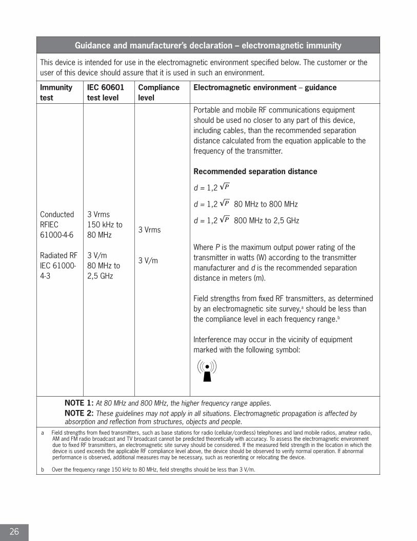
Guidance and manufacturer’s declaration – electromagnetic immunity
This device is intended for use in the electromagnetic environment specified below. The customer or the user of this device should assure that it is used in such an environment.
Immunity test IEC 60601test level
Compliance level Electromagnetic environment – guidance
Electrostatic discharge (ESD)IEC 61000-4-2
±6 kV contact±8 kV air
±6 kV contact±8 kV air
Floors should be wood, concrete or ceramic tile. If floors are covered with synthetic material, the relative humidity should be at least 30%.
Electrical fasttransient/burst
IEC 61000-4-4
±2 kV for powersupply lines
±1 kV for input/output lines
±2 kV for powersupply lines
±1 kV for input/outputlines
Mains power quality should be that of a typical commercial or hospital environment.
SurgeIEC 61000-4-5
±1 kV line(s) to line(s)
±2 kV line(s) to earth
±1 kV line(s) to line(s)
±2 kV line(s) to earth
Mains power quality should be that of a typical commercial or hospital environment.
Interruptions andvoltage variationson power supplyinput lines
IEC 61000-4-11
<5 % UT(>95 % dip in UT)for 0,5 cycle
40 % UT(60 % dip in UT)for 5 cycles
70 % UT(30 % dip in UT)for 25 cycles
<5 % UT(>95 % dip in UT)for 5 sec.
<5 % UT(>95 % dip in UT)for 0,5 cycle
40 % UT(60 % dip in UT)for 5 cycles
70 % UT(30 % dip in UT)for 25 cycles
<5 % UT(>95 % dip in UT)for 5 sec.
Mains power quality should be that of a typical commercial or hospital environment. If the user of the device requires continued operation during power mains interruptions, it is recommended that this device be powered from an uninterruptible power supply or a battery.
Power frequency(50/60 Hz)magnetic field
IEC 61000-4-8
3 A/m 3 A/mPower frequency magnetic fields should be at levels characteristic of a typical location in a typical commercial or hospital environment.
NOTE UT is the a.c. mains voltage prior to application of the test level.
26
Guidance and manufacturer’s declaration – electromagnetic immunity
This device is intended for use in the electromagnetic environment specified below. The customer or the user of this device should assure that it is used in such an environment.
Immunity test
IEC 60601 test level
Compliancelevel
Electromagnetic environment – guidance
Conducted RFIEC 61000-4-6
Radiated RFIEC 61000-4-3
3 Vrms150 kHz to 80 MHz
3 V/m80 MHz to 2,5 GHz
3 Vrms
3 V/m
Portable and mobile RF communications equipment should be used no closer to any part of this device, including cables, than the recommended separation distance calculated from the equation applicable to the frequency of the transmitter.
Recommended separation distance
d = 1,2
d = 1,2 80 MHz to 800 MHz
d = 1,2 800 MHz to 2,5 GHz
Where P is the maximum output power rating of the transmitter in watts (W) according to the transmitter manufacturer and d is the recommended separation distance in meters (m).
Field strengths from fixed RF transmitters, as determined by an electromagnetic site survey,a should be less than the compliance level in each frequency range.b
Interference may occur in the vicinity of equipment marked with the following symbol:
NOTE 1: At 80 MHz and 800 MHz, the higher frequency range applies.NOTE 2: These guidelines may not apply in all situations. Electromagnetic propagation is affected by absorption and reflection from structures, objects and people.
a Field strengths from fixed transmitters, such as base stations for radio (cellular/cordless) telephones and land mobile radios, amateur radio, AM and FM radio broadcast and TV broadcast cannot be predicted theoretically with accuracy. To assess the electromagnetic environment due to fixed RF transmitters, an electromagnetic site survey should be considered. If the measured field strength in the location in which the device is used exceeds the applicable RF compliance level above, the device should be observed to verify normal operation. If abnormal performance is observed, additional measures may be necessary, such as reorienting or relocating the device.
b Over the frequency range 150 kHz to 80 MHz, field strengths should be less than 3 V/m.
27
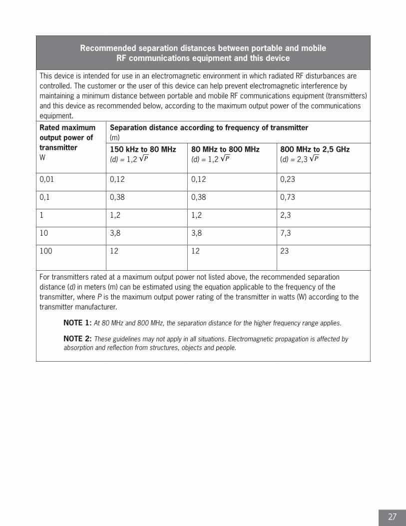
Recommended separation distances between portable and mobile RF communications equipment and this device
This device is intended for use in an electromagnetic environment in which radiated RF disturbances are controlled. The customer or the user of this device can help prevent electromagnetic interference by maintaining a minimum distance between portable and mobile RF communications equipment (transmitters) and this device as recommended below, according to the maximum output power of the communications equipment.
Rated maximum output power of transmitterW
Separation distance according to frequency of transmitter(m)
150 kHz to 80 MHz(d) = 1,2
80 MHz to 800 MHz(d) = 1,2
800 MHz to 2,5 GHz (d) = 2,3
0,01 0,12 0,12 0,23
0,1 0,38 0,38 0,73
1 1,2 1,2 2,3
10 3,8 3,8 7,3
100 12 12 23
For transmitters rated at a maximum output power not listed above, the recommended separation distance (d) in meters (m) can be estimated using the equation applicable to the frequency of the transmitter, where P is the maximum output power rating of the transmitter in watts (W) according to the transmitter manufacturer.
NOTE 1: At 80 MHz and 800 MHz, the separation distance for the higher frequency range applies.
NOTE 2: These guidelines may not apply in all situations. Electromagnetic propagation is affected by absorption and reflection from structures, objects and people.

28
NOTES:
Restep—an economical
and INNOVATIVE solution for
today’s HEALTHY Hospital.
“ “ The information presented in this brochure is intended to demonstrate a Stryker product. Always refer to the package insert, product label and/or user instructions before using any Stryker product. Products may not be available in all markets. Product availability is subject to the regulatory or medical practices that govern individual markets. Please contact your Stryker representative if you have questions about the availability of Stryker products in your area.
Stryker Corporation or its divisions or other corporate affiliated entities own, use or have applied for the following trademarks or service marks: Restep®. All other trademarks are trademarks of their respective owners or holders.
RM801005 Restep Pump Manual Cover.indd 2 1/19/17 2:54 PM
Deep Vein Thrombosis (DVT) System
User ManualMANUFACTURED FOR
1810 West Drake DriveTempe, Arizona, 85283
888.888.3433
restep.stryker.com
RM801005J Printed in the USA
RM801005 Restep Pump Manual Cover.indd 1 1/19/17 2:54 PM