© Maryam Eidini-Nezhad. All rights reserved.
188
© Maryam Eidini-Nezhad. All rights reserved.
Transcript of © Maryam Eidini-Nezhad. All rights reserved.

© Maryam Eidini-Nezhad. All rights reserved.

i
ORIGAMI-INSPIRED STRUCTURES AND MATERIALS: ANALYSIS AND
METAMATERIAL PROPERTIES AND
SEISMIC DESIGN OF HYBRID MASONRY STRUCTURAL SYSTEMS
BY
MARYAM EIDINI-NEZHAD
DISSERTATION
Submitted in partial fulfillment of the requirements
for the degree of Doctor of Philosophy in Civil Engineering
in the Graduate College of the
University of Illinois at Urbana-Champaign, 2015
Urbana, Illinois
Doctoral Committee:
Professor Iwona Jasiuk, Chair
Professor Taher Saif
Professor Sascha Hilgenfeldt
Assistant Professor Ahmed Elbanna

ii
Abstract
This dissertation includes two major sections. The first section presents the research on creating and
studying novel classes of origami-inspired metamaterials and structures. The second section deals
with seismic design of hybrid masonry structural systems.
1) Origami-Inspired Structures and Materials
Origami, the traditional Japanese art of paper folding, has been recognized to be a significant source
of inspiration in science and engineering. Specifically, its principles have been used for innovative
design of mechanical metamaterials for which material properties arise from their geometry and
structural layout. Most research on origami-inspired materials relies on known patterns, especially on
the Miura-ori, i.e., a classic origami pattern with outstanding properties and a wide range of
applications.
Motivated by outstanding properties and a broad range of applications of the Miura-ori, in this
dissertation, inspired by the kinematics of a one-degree of freedom zigzag strip, we create a novel
class of cellular folded sheet mechanical metamaterials. The class of the patterns combines origami
folding techniques with kirigami cutting. Using both analytical and numerical models, we study the
key mechanical properties of the folded materials. We show that they possess properties as
remarkable as those of the Miura-ori on which there has been a surge of research interest.
Consequently, the introduced patterns are single degree of freedom (DOF), developable, rigid-
foldable and flat-foldable.
Furthermore, we show that depending on the geometry, these materials exhibit both negative and
positive in-plane Poisson’s ratio. By introducing a novel class of zigzag-base materials, the current
study extends the properties of the Miura-ori to those of the class of one-DOF zigzag-base patterns,
and our work shows that Miura-ori is only one pattern in this class with such properties. Hence, by
expanding upon the design space of the Miura-ori, our patterns are appropriate for a wide range of
applications, from mechanical metamaterials to light cellular foldcore sandwich panels and
deployable structures at both small and large scales. Furthermore, this study unifies the concept of
the in-plane Poisson’s ratio from the literature for similar materials and extends it to this novel class
of zigzag-base folded sheet metamaterials.
Moreover, in this dissertation, by dislocating the zigzag strips of a Miura-ori pattern along the joining
ridges, we create a class of one-degree of freedom (DOF) cellular mechanical metamaterials. We
further show that dislocating zigzag strips of the Miura-ori along the joining ridges preserves and/or
tunes the outstanding properties of the Miura-ori. The introduced materials are lighter than their
corresponding Miura-ori patterns due to the presence of holes in the patterns. They are also amenable
to similar modifications available for Miura-ori which make them appropriate for a wide range of
applications across the length scales.
Additionally, we study the Eggbox pattern. Similarly to Miura-ori, a regular Eggbox folded sheet
includes parallelogram facets which are connected along fold lines. However, Eggbox sheets cannot
be folded from a flat sheet of material, and contrary to Miura-ori which has received considerable
interest in the literature, there are fewer studies available on Eggbox folded sheet material. By
employing both analytical and numerical models, we review and study the key in-plane mechanical
properties of the Eggbox folded sheet, and we present cellular folded metamaterials containing

iii
Miura-ori and Eggbox cells. The entire structure of the folded materials is a one-DOF mechanism
system and, similarly to Eggbox sheets, the materials composed of layers of Eggbox folded sheets are
bi-directionally flat-foldable, resulting in a material flexible in those directions, but stiff in the third
direction.
2) Seismic Design of Hybrid Masonry Structural Systems
Hybrid masonry is an innovative seismic lateral-load resisting system. The system comprises
reinforced masonry panels within a steel-framed structure as well as steel connector plates which
attach the surrounding steel frame to the masonry panel. Depending on the interfacial conditions
between a masonry panel and the steel frame, the system is categorized into three major groups:
Types I, II and III.
The first part of the research on hybrid masonry systems, in this dissertation, includes a series of
exploratory studies aimed at understanding the global behavior of various types of hybrid masonry
panels and setting the stage for the study on seismic design of the systems. In this regard,
computational analyses were carried out to study the distribution of lateral forces between a masonry
panel and a frame in various types of hybrid masonry structural systems. The results are used to
demonstrate differences in lateral-force distributions in hybrid masonry systems with different
boundary conditions and with various panel aspect ratios as well as with different stiffness of the
wall to that of the frame.
Furthermore, this study presents the general methodology for seismic design of Type I hybrid
masonry systems as well as the steps of a capacity design process in which two favorable ductile
modes of behavior are considered: steel connector plates behaving as fuses or flexural yielding of the
masonry panels. Moreover, using the proposed approaches we design several prototype buildings
located in a high seismic region and investigate viability of hybrid masonry as a new seismic lateral-
load resisting system. According to this design framework and the exploratory studies, both
approaches are shown to be feasible for developing realistic system configurations.
Finally, in this study, an integrated approach for performance-based seismic analysis and design of
hybrid masonry Type I systems with fuse connector plates is presented. The procedure used in this
study is based on the Capacity Spectrum Method. The proposed method includes an iterative process
through which a hybrid masonry structural system with fuse connector plates is designed depending
on its energy dissipation capacity. In this regard, the value of the system R factor is regulated in the
process. In this study, application of the method for design of a sample hybrid masonry building
system is presented.

iv
To my family

v
Acknowledgements
First and foremost, I would like to thank all those genuine professors who promote and
encourage academic integrity, sincerity and responsibility, by their actions.
I would like to thank Dr. Jasiuk, Dr. Elbanna, Dr. Saif and Dr. Hilgenfeldt for serving on my
dissertation committee and for their feedback.
I gratefully acknowledge the support of Schlumberger fellowship during the first two years of
my PhD studies. Nevertheless, the prestigious fellowship appeared like an obstacle on my
academic progress because of the inappropriate treatment of the award by the others and that the
issue was not resolved at the early stages when it was reported. When there is a mistake (even
intentional mistakes), the right and the sensible way is to compensate for the mistake rather than
covering up the mistake by numerous other mistakes and transferring the mistake from one to
another (and consequently leaving the person among numerous unnecessary problems). I am
glad though for having to change my research area. Apart from experiencing a new research
area, overcoming the unusual challenges and the unnecessary difficulties that I have faced, has
improved my self-confidence and has further proved to me that always “honesty is the best
policy”.
I am thankful to all my friends, teachers and professors for their support and/or friendship.
Last but not least, I wish to express my sincere gratitude to my family for their never-ending
support and encouragement.
vi
Table of Contents
List of Tables ...................................................................................................................... x
List of Figures ................................................................................................................... xi
1 Introduction ................................................................................................................. 1
2 Origami Engineering .................................................................................................. 3
2.1 Origami Engineering and Sustainable Development .......................................................... 4
2.1.1 Sustainable design in civil engineering and architecture using origami techniques ... 6
2.2 Application of Origami in Engineering .............................................................................. 7
2.2.1 Deployable structures.................................................................................................. 7
2.2.1.1 Rigid foldable origami (rigid origami) ........................................................................... 8
2.2.2 Impact absorbing devices ............................................................................................ 8
2.2.3 Modifying mechanical properties of materials and structures by corrugation ........... 9
2.2.4 Metamaterials .............................................................................................................. 9
2.2.5 Other engineering applications ................................................................................. 10
2.3 Major Origami Patterns Applied in Engineering .............................................................. 11
3 Miura- and Eggbox-inspired Cellular Folded Materials: Synthesis, Analysis and
Mechanical Properties ..................................................................................................... 14
3.1 Introduction ....................................................................................................................... 15
3.2 Numerical Modeling of Origami-like Structures .............................................................. 18
3.2.1 Bar-framework approach .......................................................................................... 19
3.3 Mechanical Properties of Miura-ori and Eggbox Folded Sheet Materials ....................... 21
3.3.1 Miura-ori pattern ....................................................................................................... 21
3.3.1.1 Stiffness analysis of Miura-based folded Materials...................................................... 22
3.3.1.2 In-plane response of Miura-ori sheet ............................................................................ 24
3.3.2 Eggbox pattern .......................................................................................................... 26
3.3.2.1 Geometry of Eggbox .................................................................................................... 26
3.3.2.2 Stiffness analysis of Eggbox sheet ............................................................................... 27
3.3.2.3 In-plane response of Eggbox sheet ............................................................................... 28
3.4 A Framework to Obtain Poisson’s Ratio Computationally .............................................. 30
3.5 Metamaterials Composed of Miura-ori and Eggbox Cells ............................................... 31

vii
3.6 Non-developable Zigzag-base Sheets and Zigzag-base Tubes ......................................... 33
3.7 Concluding Remarks ......................................................................................................... 34
3.8 Supplementary Materials: In-plane Stiffness .................................................................... 39
3.8.1 Miura-ori ................................................................................................................... 39
3.8.2 Eggbox ...................................................................................................................... 39
4 Unravelling Metamaterial Properties in Zigzag-base Folded Sheets .................. 42
4.1 Introduction ....................................................................................................................... 43
4.2 Kinematics of a Folded One-DOF Zigzag Strip ............................................................... 44
4.3 BCHn Zigzag-base Patterns............................................................................................... 45
4.4 Mechanical Properties of BCHn Patterns .......................................................................... 48
4.5 Discussion ......................................................................................................................... 56
4.6 Materials and Methods ...................................................................................................... 58
4.7 Supplementary Materials .................................................................................................. 60
4.7.1 Geometry, pattern tessellation and combination ....................................................... 60
4.7.2 Number of degrees of freedom of the patterns ......................................................... 61
4.7.3 In-plane stretching response of BCHn sheets ............................................................ 62
4.7.3.1 Poisson’s ratio .............................................................................................................. 62
4.7.3.2 Stretching stiffness ....................................................................................................... 65
4.7.4 Cellular folded metamaterial ..................................................................................... 68
4.7.5 Experimental responses of the patterns..................................................................... 70
4.7.5.1 In-plane behavior .......................................................................................................... 70
4.7.5.2 Out-of-plane behavior .................................................................................................. 70
4.7.6 Numerical investigation of patterns behavior ........................................................... 71
4.7.6.1 Numerical calculation of the number of DOFs of the patterns ..................................... 71
5 Tuning the Miura-ori Properties by Dislocating the Zigzag Strips ..................... 76
5.1 Introduction ....................................................................................................................... 76
5.2 Geometry of the Patterns .................................................................................................. 78
5.3 Key Mechanical Behaviors of the Patterns ....................................................................... 79
5.4 Concluding Remarks ......................................................................................................... 82
5.5 Supplementary Materials .................................................................................................. 84
viii
5.5.1 Out-of-plane behavior of the patterns ....................................................................... 84
5.5.2 Other variations of ZCH and their assemblages ....................................................... 84
5.5.3 Comparison of ZCH with Miura-ori and BCH2 for the same amount of mass ........ 86
5.5.4 Global behavior of the patterns studied numerically ................................................ 90
6 Lateral Force Distributions for Various Types of Hybrid Masonry Panels ....... 92
6.1 Introduction ....................................................................................................................... 92
6.2 Example Structure Considered in the Analyses ................................................................ 93
6.3 Lateral Load Transfer Mechanism in Hybrid Masonry Panels ......................................... 94
6.3.1 Hybrid Type I ............................................................................................................ 95
6.3.2 Hybrid Types II and III ............................................................................................. 97
6.4 Effect of Aspect Ratio and Wall Stiffness on Distribution of Lateral Force between Wall
and Frame ................................................................................................................................ 100
6.5 Effect of Story Level on Distribution of Lateral Force between Wall and Frame ......... 102
6.6 Effect of the Lateral Load Patterns on Distribution of the Lateral Forces between Wall
and Frame ................................................................................................................................ 104
6.7 Concluding Remarks ....................................................................................................... 105
7 Seismic Design and Viability of Hybrid Masonry Building Systems ................. 108
7.1 Introduction ..................................................................................................................... 109
7.2 Hybrid Masonry Type I .................................................................................................. 111
7.2.1 Force transfer mechanisms ..................................................................................... 111
7.2.2 Ductile limit states .................................................................................................. 114
7.2.3 Non-ductile break-out/bearing strength .................................................................. 115
7.3 Seismic Design Methodologies for Hybrid Masonry Building Systems ........................ 116
7.3.1 Case a) Inelasticity concentrated in connector plates ............................................. 117
7.3.2 Case b) Inelasticity concentrated in vertical bars of reinforced masonry panels .... 117
7.4 Major Parameters Affecting Shear Demand on Lateral-Load Resisting Elements of a
Hybrid Masonry System .......................................................................................................... 118
7.4.1 Response modification coefficient (R) ................................................................... 118
7.4.2 Number of hybrid masonry panels .......................................................................... 119
7.4.3 Number of steel connectors per panel (NCP_panel) .................................................... 119
7.5 Seismic Design Process .................................................................................................. 120

ix
7.5.1 Case a) Inelasticity concentrated in steel connector plates ..................................... 120
7.5.2 Case b) Inelasticity concentrated in vertical bars of reinforced masonry panels .... 121
7.5.3 Design of hybrid masonry structural panels ........................................................... 122
7.5.3.1 Case a) Inelasticity concentrated in steel connector plates ......................................... 122
7.5.3.2 Case b) Inelasticity concentrated in vertical bars of reinforced masonry panels ........ 125
7.6 Viability of Hybrid Masonry as a Lateral-Load Resisting System ................................. 125
7.6.1 Description of Prototype Buildings ........................................................................ 125
7.6.2 Design of Prototype Buildings ................................................................................ 126
7.6.2.1 Case a) Inelasticity concentrated in steel connector plates ......................................... 126
7.6.2.2 Case b) Inelasticity concentrated in vertical bars of reinforced masonry panels ........ 129
7.7 Summary, Conclusions and Future Research ................................................................. 129
7.8 Supplementary Materials ................................................................................................ 131
7.8.1 Summary of calculations for Case a) ...................................................................... 131
7.8.2 Summary of calculations for Case b) ...................................................................... 133
8 Capacity Spectrum-Based Seismic Design of Type I Hybrid Masonry Structural
Systems with Fuse Connectors ..................................................................................... 135
8.1 Introduction ..................................................................................................................... 135
8.1.1 Major Advantages of Hybrid Masonry ................................................................... 136
8.2 Hybrid Masonry Type I .................................................................................................. 138
8.2.1 Lateral load analysis in hybrid masonry Type I ...................................................... 138
8.2.2 Lateral stiffness of hybrid masonry Type I ............................................................. 141
8.3 Performance-based Seismic Design of Hybrid Masonry Structural Systems ................. 143
8.4 Description of a Prototype Building ............................................................................... 147
8.5 Design of the Prototype Building ................................................................................... 148
8.6 Concluding Remarks and Future Research ..................................................................... 153
Appendix A: Artworks Related to the BCH2 Pattern ................................................ 157
References ....................................................................................................................... 158

x
List of Tables
Table 2.1: Some major origami patterns applied in engineering, their properties and applications.
.................................................................................................................................. 12
Table 4.1: Summary of main points on the in-plane Poisson’s ratio of the class of zigzag-base
folded metamaterials. ............................................................................................... 65
Table 7.1: Main considerations in capacity design of hybrid masonry panels. ......................... 117
Table 7.2: Panel shear forces from lateral-load analysis (Case a). ............................................ 128
Table 7.3: Parameters considered for design of reinforced masonry panels. ............................. 128
Table 7.4: Panel shear forces from lateral-load analysis (Case b). ............................................ 129
Table 7.5: Number of steel connectors per panel and shear demand per connector (Case a). ... 131
Table 7.6: Moment demands and cross-section geometry at the top of fuses (Case a). ............ 132
Table 7.7: Moment demands and cross-section geometry at the bottom of fuses (Case a). ...... 132
Table 7.8: Check of panel break-out strength and shear demands on panels (Case a). ............. 132
Table 7.9: Summary of shear strength calculations of masonry panels for various configurations
of bars per MSJC 2008 Strength method. .............................................................. 133
Table 7.10: Number of steel connectors per panel and shear demand per connector (Case b). . 133
Table 7.11: Moment demands and cross sections geometry (Case b). ...................................... 134
Table 7.12: Check of panel break-out strength and shear demands on panels (Case b). ........... 134
Table 8.1: Critical points of hysteretic response for the fuse used in the design. ...................... 150
Table 8.2: The number of steel connectors used per panel and lateral-load capacity of each
hybrid masonry panel. ............................................................................................ 150
Table 8.3: The data needed to draw the capacity curve of the system. ...................................... 150

xi
List of Figures
Figure 2.1: Applications of origami in Engineering with emphasis on deployable origami
structures. ................................................................................................................... 4
Figure 2.2: Some applications of origami in engineering. (a) Deployable medical stents [14]. (b)
Metamaterial [15]. (c) Folded core [16]. (d) Car crash boxes [9]. ............................ 4
Figure 2.3: (a, b) Investment Council Headquarters of Abu Dhabi, Al Bahr towers [29], with
origami-inspired kinetic shading and solar responsive screen; (c) “lightweight
origami structure” [28]. .............................................................................................. 7
Figure 2.4: Dynamic façade; Kiefer Technic showroom Bad Gleichenberg Giselbrecht (pictures
by Paul Ott). ............................................................................................................... 7
Figure 2.5: Folded plates [38]. ....................................................................................................... 9
Figure 2.6: Miura-ori sheet with in-plane and out-of-plane Poisson’s ratio of opposite signs [23].
.................................................................................................................................. 10
Figure 2.7: (a) Stacked Miura folds and unfolds uniformly with negative Poisson's ratio in all
directions and highly anisotropic material properties [10]. (b) Curved corrugated
shell structures [40]. ................................................................................................. 10
Figure 2.8: (a) Meguro Persimmon Hall in Tokyo with Miura-ori pattern applied for the ceiling
[12]. (b) Resonant Chamber using Ron Resch pattern [43]. .................................... 11
Figure 3.1: Illustration of 4 by 3 sheets of Miura-ori and Eggbox (m1=4, m2=3): (a) Miura-ori.
(b) Eggbox. .............................................................................................................. 15
Figure 3.2: Herringbone pattern in natural systems. (a) Common beech [79]. (b) Hornbeam [80].
(c) Insect wing [69]. (d) Pattern formed by biaxial compression of a thin film at the
top of a soft substrate [71]. (e) Natural pattern in turkey embryo [75]. ................... 16
Figure 3.3: (a) Tube unit cell with a rhombus cross section decomposed into Miura-ori and Egg-
box cells. The parameters shown in the figure are defined in the Sections on Miura-
ori and Eggbox. (b) A BCH2-based tube forming two different scales Eggbox
surfaces at the sides. ................................................................................................. 17
Figure 3.4: Tubular materials forming Eggbox surfaces. (a) A tubular material decomposed to
layers of Eggbox sheets. (b) A novel material created with special assembly of
BCH2 sheets resulting in Eggbox surfaces parallel to the horizontal plane. ............ 18
Figure 3.5: (a) Illustration of the bar framework approach to model folded shell structures. Fold
lines and vertices are replaced with the bars and hinges, respectively. (b) Geometry
of Miura-ori unit cell. ............................................................................................... 22
Figure 3.6: Stiffness analysis of Miura-ori pattern. ..................................................................... 23

xii
Figure 3.7: Stiffness analysis of stacked Miura-ori pattern. ........................................................ 23
Figure 3.8: Kx/k for a Miura-ori unit cell with a=b=1: (a) Wei et al.’s equation [39]. (b)
modified equation (present work). ........................................................................... 25
Figure 3.9: Ky/k for a Miura-ori unit cell with a=b=1: (a) Wei et al.’s equation [39]. (b)
Modified equation (present work). .......................................................................... 26
Figure 3.10: Geometry of Eggbox unit cell. The geometry of a regular Eggbox sheet can be
parameterized by the geometry of a parallelogram facet (ae, be and ), and one fold
angle, e.g. e [0, ] which is the angle between fold lines be and the z’-axis. Other
important angles in the figure are angle between the fold lines ae and the z’-axis,
i.e., e [0, ]; and dihedral fold angles between parallelogram facets e [0, ]
and e [0, ], joining along fold lines ae and be, respectively. ............................ 27
Figure 3.11: Stiffness analysis of Eggbox pattern. ...................................................................... 28
Figure 3.12: In-plane stretching stiffness Kx’/k of Eggbox unit cell with a=b=1. ....................... 29
Figure 3.13: Simulation set up to compute Poisson’s ratio numerically. (a) Miura-ori. (b)
Eggbox. .................................................................................................................... 31
Figure 3.14: First mode illustrating rigid origami behavior: (a) Miura-ori. (b) Eggbox unit cell.
.................................................................................................................................. 31
Figure 3.15: Poisson’s ratio computed numerically: (a) Miura-ori. (b) Eggbox unit cell. .......... 31
Figure 3.16: (a) Tube cell with rhombus cross section. (b) General tube cell geometry, for the
kite-shape cross section, 1 2A Aa a and 1 2B Ba a . ............................................... 32
Figure 3.17: Miura-ori based tube with parallelogram cross section. (a) Unfolded Miura-ori unit
cells with mountain (blue continuous lines) and valley (red dashed lines)
assignments. (b) Partially folded Miura-ori cells constructing the top and bottom of
the tube cell. (c) Tube cell with parallelogram cross section. ................................. 34
Figure 3.18: (a-d) Sample alignments of tube cells with parallelogram cross sections, and
sample one-DOF mechanism materials made from them. (e-g) Tessellations and/or
combinations of these units results in various configurations of materials. ............ 36
Figure 3.19: (a) Material with Miura surfaces at the top and bottom. (b) Material with Eggbox
surfaces at the top and bottom. (c) Bi-directionally flat-foldable tubular materials
with parallelogram cross sections decomposed to Eggbox sheets. .......................... 36
Figure 3.20: Non-developable zigzag-base patterns constructed from Miura-ori cells with
identical kinematics and different heights of the unit cells (the rule is similar to that
used in the stacking, but the cells possessing different heights are connected side-
by-side instead of stacking). .................................................................................... 37
Figure 3.21: Modified zigzag-base tubes constructed from zigzag strips with identical
kinematics and different heights (in their semi-folded states) and various acute

xiii
angles of parallelograms. The presented tubes are flat-foldable in one direction, and
they provide a flat and load carrying surface in their deployed configurations. ...... 37
Figure 3.22: A side-by-side assembly of the tubes shown in the figure above. The structures is
flat-foldable in one direction and can carry loads in its deployed configuration. .... 38
Figure 3.23: (a) Sample graded bi-directionally flat-foldable cellular material with one-DOF
mechanism inspired by Miura-based tube with parallelogram cross section. The
sample material includes 3 layers of Eggbox with the same Poisson’s ratio bonded
along joining fold lines. (b, c) Fully folded states in 2 orthogonal directions. ........ 38
Figure 3.24: Effect of fold lengths on in-plane stretching stiffness Kx’/k of Eggbox unit cell: Left
(ae=1 and be=5); Right (ae=5 and be=1). ................................................................ 41
Figure 4.1: From Miura-ori to zigzag-base foldable metamaterials possessing different scales of
zigzag strips. (a) A Miura-ori unit cell contains two V-shapes aligned side-by-side
forming one concave valley and three convex mountain folds (or vice versa, if the
unit cell is viewed from the opposite side). (b) Top view of a V-shape fold including
two identical parallelogram facets connected along the ridges with length a. Its
geometry can be defined by the facet parameters a, b, and the angle [0, ].
(c) Two different scales of V-shapes with the same angle are connected along
joining fold lines. The length b of the parallelogram facets in the left zigzag strip of
V-shapes is half that of the strip on the right in the unit cell shown. ....................... 46
Figure 4.2: Geometry of BCHn pattern. (a) Geometry of the unit cell. The geometry of a sheet of
BCHn can be parameterized by the geometry of a parallelogram facet (a, b and ),
half number of small parallelogram facets (n) and fold angle [0, ] which is the
angle between fold lines b and the x-axis. Other important angles in the figure are
fold angle between the facets and the xy-plane, i.e., [0, /2]; angle between the
fold lines a and the x-axis, i.e., [0, ]; and dihedral fold angles between
parallelograms, [0, ] and [0, ], joined along fold lines a and b,
respectively. (b) A sheet of BCH2 with m1=2, m2=3 and outer dimensions of L and
W. ............................................................................................................................. 47
Figure 4.3: Sample patterns including BCHn and cellular folded metamaterials. (a) A sheet of
BCH2. (b) A sheet of BCH3. Adding one layer of small parallelograms to the first
row reduces the DOF of the system to 1 for rigid origami behavior. (c) Combination
of BCH2 and layers of large and small parallelograms with the same geometries as
the ones used in the BCH2. (d) Combination of BCH3 and layers of large and small
parallelograms with the same geometries as the ones used in the BCH3. (e) Sheet of
BCH3 and layers of small parallelograms with the same geometries as the ones used
in the BCH3. (f) A sheet composed of various BCHn and Miura-ori cells with the
same angle . (g) A stacked cellular metamaterial made from 7 layers of folded
sheets of BCH2 with two different geometries. (h) Cellular metamaterial made from
2 layers of 3x3 sheets of BCH2 with different heights tailored for the stacking
purpose, and bonded along the joining fold lines. The material is flat-foldable in one
direction. .................................................................................................................. 51

xiv
Figure 4.4: In-plane Poisson’s ratios of the metamaterials introduced in this work. (a) 5x4 (m1=5
and m2=4) BCH2 sheet (left image) and its corresponding Miura-ori sheet (right
image) with the same geometry, and the same amount of material. Projected lengths
of the zigzag strips along x’-x’ line parallel to the x-axis is used to obtain z and L is
used to obtain e e . Both sheets have identical z , but they have different e e . (b) In-
plane kinematics ( z ) for the class of metamaterials. (c) In-plane Poisson’s ratio
considering the end-to-end dimensions ( e e ) for the unit cell of Miura-ori and BCH2
patterns with a=b. (d) In-plane Poisson’s ratio considering the end-to-end
dimensions ( e e ) for sheets of Miura-ori and BCH2 with m1=5 and a=b. ............... 52
Figure 4.5: In-plane Poisson’s ratio of the BCH2 sheet for an infinite configuration. Poisson’s
ratio obtained by considering the projected length of the zigzag strips, z , versus
Poisson’s ratio considering the end-to-end dimensions of the sheet when the sheet
size approaches infinity, e e (a=b and 1m ). The latter is equivalent to the
Poisson’s ratio of a repeating unit cell of BCH2 within an infinite tessellation. The
figure shows that, contrary to the Miura-ori, the transition towards positive
Poisson’s ratio is present for an infinite configuration of the BCH2 sheet. ............. 53
Figure 4.6: Ratio of in-plane stiffness of Miura-ori cell to that of the BCH2 in the x and y
directions. The results show that depending on the geometry and considering the
same amount of material, BCH2 can be more or less stiff than its corresponding
Miura-ori cell in the x and y directions. (a) a/b=2. (b) a/b=1. (c) a/b=1/2............. 54
Figure 4.7: Behavior of sheet of the BCH2 under bending and the results of the eigen-value
analysis of a 3 by 3 pattern of BCH2. (a) A sheet of BCH2 deforms into a saddle-
shaped under bending (i.e., a typical behavior seen in materials with a positive out-
of-plane Poisson’s ratio). (b) Twisting, (c) saddle-shaped and (d) rigid origami
behavior (planar mechanism) of a 3 by 3 pattern of BCH2 (a=1; b=2; 60 ).
Twisting and saddle-shaped deformations are the softest modes observed for a wide
range of material properties and geometries. For large values of Kfacet/Kfold the rigid
origami behavior (planar mechanism) is the softest deformation mode of the sheets.
.................................................................................................................................. 55
Figure 4.8: Outcomes of the current study. Inspired by the Miura-ori to create the novel BCHn
zigzag-base patterns with a broad range of applications. ........................................ 56
Figure 4.9: BCH2 and BCH3 and their combinations with row/rows of small and/or large
parallelograms. (a) A BCH2 and a BCH3. (b) A BCH2 and a BCH3 combined with a
row of small parallelograms with the same geometry as the one used in the
corresponding BCH. (c) A BCH2 and a BCH3 combined with a row of large
parallelograms with the same geometry as the one used in their corresponding BCH.
(d) A BCH2 and a BCH3 combined with rows of small and large parallelograms
with the same geometry as the one used in their corresponding BCH. ................... 60

xv
Figure 4.10: Constrained DOFs by implicit formation of the structure of the Miura-ori unit cell
between adjoining unit cells of BCH2 and BCH3 in the pattern. (a) Although the
unit cell of the pattern shown, BCH2, does not have Miura-ori unit cell, the Miura-
ori unit cell structure formed implicitly in the tessellation makes the whole BCH2
pattern fold with one-DOF planar mechanism. (b) In the symmetric tessellation of
identical BCH3, except for the small parallelogram facets of the first row, all other
independent DOFs in the unit cell of BCH3 are constrained by the structure of the
Miura-ori cell formed between two adjoining unit cells. ......................................... 61
Figure 4.11: Concept of Poisson’s ratio considering the end-to-end dimensions. Figure shows
two identical 2x2 Miura-ori tessellations. The 2 rows of small Mira-ori cells with
the same z as that of the 2x2 sheet are attached to the left sample. Length b of the
small cells are 1/5 of that of the large cells (i.e., the number of small cells per each
large cell is 5 (n=5)). ................................................................................................ 63
Figure 4.12: Geometry of Miura-ori cell. .................................................................................... 64
Figure 4.13: In-plane stiffness for the BCH2 with a=b=1. (a) Kx/k. (b) Ky/k. ............................. 67
Figure 4.14: Sample stacked cellular folded metamaterials. The samples include layers of BCH2
with two different geometries tailored for stacking. One alternating layer is almost
unfolded ( 5 ) in these samples. (a) Two BCH2 with different heights are
attached along the joining fold lines. (b) 4 layers of BCH2 with two different
heights are attached along the joining fold lines. (c) 4 layers of 2x2 BCH2 with two
different heights are attached along the joining fold lines. ...................................... 70
Figure 4.15: Behavior of the sheet of BCH3 under bending and the results of eigen-value
analysis of a 3 by 3 pattern of BCH3. (a) Sheet of BCH3 deforms into a saddle-
shaped under bending which is typical behavior for materials having a positive
Poisson’s ratio. (b) Twisting, (c) saddle-shaped and (d) rigid origami behavior
(planar mechanism) of a 3 by 3 pattern of BCH3 (with a=1; b=2; 60 ). ......... 73
Figure 4.16: Behavior of a sheet of the pattern shown in Figure 4.3(c) under bending and results
of eigen-value analysis of a 2 by 3 sheet of the pattern. (a) The sheet deforms into a
saddle-shaped under bending (i.e., typical behavior seen in materials having a
positive Poisson’s ratio). (b) Twisting, (c) saddle-shaped from two different views
and (d) rigid origami behavior (planar mechanism) of a 2 by 3 pattern shown in
Figure 4.3(c) (with a=1; b=2; 60 ). .................................................................. 74
Figure 4.17: Behavior of a sheet of the pattern shown in Figure 4.3(d) under bending and the
results of eigen-value analysis of a 2 by 3 sheet of the pattern. (a) The sheet
deforms into a saddle-shaped under bending, i.e. a typical behavior seen in
materials having a positive Poisson’s ratio. (b) Twisting, (c) saddle-shaped from
two different views and (d) rigid origami behavior (planar mechanism) of a 2 by 3
pattern shown in Figure 4.3(d) (with a=1; b=2; 60 ). ..................................... 75
Figure 5.1: Crease patterns of sample zigzag-base folded materials introduced in the current
work and their unit cell. (a) Changing the direction of the offset from a zigzag strip

xvi
to the next adjoining one results in a pattern with holes oriented in different
directions - the direction of the offsets are shown with blue arrows. (b) Arranging
the offsets all to one side, results in zigzag strips with the holes all oriented with the
same direction. (c) Crease pattern of the unit cell. In the figures, the blue and red
lines show mountain and valley folds, respectively, and hatched black areas
represent the places of the cuts. ............................................................................... 78
Figure 5.2: Geometry of ZCH pattern. (a) Geometry of the unit cell. The geometry of a ZCH
sheet can be parameterized by the geometry of a parallelogram facet, hole width bh,
and fold angle [0, ] which is the angle between the edges b0 (and b) and the x-
axis in the xy-plane. Other important angles in the figure are fold angle between the
facets and the xy-plane, i.e., [0, /2]; angle between the fold lines a and the x-
axis, i.e., [0, ]; Dihedral fold angles between parallelogram facets [0, ]
and [0, ], joining along fold lines a and b0, respectively. (b) A ZCH sheet
with m1=2 and m2=3 and outer dimensions L and W. .............................................. 79
Figure 5.3: Sample patterns of ZCH. (a-e) Sample ZCH sheets created by changing the direction
and/or the amount of the offsets, in placement of one zigzag with respect to its
neighboring one, in the patterns. Note that by changing the height h, the length and
width of the parallelogram facets, the hole width (pattern (e)) and other changes
(e.g., similarly to the Miura-ori, changing the geometry of the facets to get the
curved version and others) we can produce numerous graded and/or shape
morphing materials/structures. ................................................................................. 81
Figure 5.4: In-plane Poisson’s ratio of metamaterials introduced in this work with infinite
configurations. (a) Poisson’s ratio of Miura-ori and ZCH sheets for ( 1m ) and
a=b, and two different hole widths - the values correspond to the Poisson’s ratios of
the repeating unit cells of sheets as well. (b) Poisson’s ratio of repeating unit cells
of ZCH and Miura-ori sheets if /b a . ................................................................ 82
Figure 5.5: Results of the eigenvalue analysis of a sample ZCH sheet. (a) Twisting, (b) saddle-
shaped and (c) rigid origami behavior (planar mechanism) of a 4x4 and a 4x3
patterns of ZCH with the holes located on various directions (a=1; b=2; =60). .. 82
Figure 5.6: Behavior of sheets of the ZCH patterns under bending. ZCH Sheets deform into
saddle-shaped curvatures under bending. ................................................................ 84
Figure 5.7: A developable ZCH pattern with augmented bonding areas. .................................... 85
Figure 5.8: A curved ZCH pattern. .............................................................................................. 85
Figure 5.9: Cellular foldable metamaterials. (a, b) Stacked cellular metamaterials made from 7
layers of folded ZCH sheets. Each material includes two different geometries of
similar sheets. (c) Interleaved ZCH tubular materials. (d-f) Materials made from
various assemblages of ZCH tubes. (g) Sample ZCH tube with a parallelogram
cross section. ............................................................................................................ 86

xvii
Figure 5.10: Sample ZCH with its corresponding Miura-ori and BCH2 sheets. (a) A 4x3 ZCH
sheet with its corresponding Miura-ori with b=2a, =70 and bh=0.3b. (b) A 4x3
ZCH sheet with its corresponding BCH2 sheet with b=2a, =70 and bh=0.3b. (c) A
4x3 ZCH sheet with its corresponding Miura-ori with b=2a, =30 and bh=0.3b. . 88
Figure 5.11: Density of ZCH compared with that of its corresponding Miura-ori. (a) m1=4,
b/a=2 and bh=0.3b. (b) m1=∞, b/a=2 and bh=0.3b. (c) m1=∞, b/a=5 and bh=0.3b.
(d) m1=∞, b/a=2 and bh=0.5b. ................................................................................. 89
Figure 5.12: Density of ZCH compared with that of its corresponding BCH2 sheet. (a) m1=4,
b/a=2 and bh=0.3b. (b) m1=∞, b/a=2 and bh=0.3b. (c) m1=∞, b/a=5 and bh=0.3b.
(d) m1=∞, b/a=2 and bh=0.5b. ................................................................................. 90
Figure 5.13: Results of the eigenvalue analysis of a sample ZCH sheet. (a) Twisting, (b) saddle-
shaped and (c) rigid origami behavior (planar mechanism) of a 4x4 and a 4x3
patterns of ZCH with the holes located on the same directions (a=1; b=2; =60). 91
Figure 6.1: Four-story one-bay steel frame used in the analyses. ................................................ 94
Figure 6.2: (a) Hybrid masonry panel Type I; (b) Schematic connection of elements in a hybrid
masonry panel Type I............................................................................................... 97
Figure 6.3: Sample vertical stress distribution for hybrid Types I, IIa and IIIa for the example
frame with aspect ratio 1.5 under triangular lateral load pattern. ............................ 98
Figure 6.4: (a) Sample vertical stress distribution in shear wall system for the example frame
with aspect ratio 1.5 under triangular lateral load pattern. (b) Ratio of overturning
moment in the wall to that of the frame in the 1st and 4th stories for shear wall
system and hybrid Type IIIa. ................................................................................... 99
Figure 6.5: Wall contribution of story overturning moment in the first story for the frames with
different aspect ratios in various types of hybrid panels for two different wall
thicknesses. ............................................................................................................ 101
Figure 6.6: Ratio of wall contribution of story overturning moment to that of the frame
contribution in the first story for the frames with different aspect ratio in various
types of hybrid panels for two different wall thicknesses...................................... 102
Figure 6.7: Wall contribution to story overturning moment in different stories for the frames
with different aspect ratio in hybrid Type I. .......................................................... 103
Figure 6.8: Wall contribution to story overturning moment in different stories for the frames
with different aspect ratio in hybrid Type IIa. ....................................................... 103
Figure 6.9: Wall contribution to story overturning moment in different stories for the frames
with different aspect ratio in hybrid Type IIIa. ...................................................... 104
Figure 6.10: Effect of Triangular (T), and Rectangular (R) lateral load pattern on distribution of
lateral forces between the wall and frame in hybrid masonry panels. ................... 105

xviii
Figure 7.1: (a) Hybrid masonry Type I; (b) Schematic connection of elements in hybrid masonry
Type I building systems. ........................................................................................ 112
Figure 7.2: Parameters used in lateral load analysis of hybrid masonry Type I. ....................... 114
Figure 7.3: Flexural failure modes in hybrid masonry Type I. (a) Flexural yielding of connector
plates. Yielding of connector plates are shown in circles. (b) Flexural yielding of
masonry panels. Flexural cracks at the heel and toe crushing are shown on the
bottom left and right sides of the panel, respectively. To make the deformed shapes
more illustrative, the gaps are shown wider than their normal sizes in a scaled
picture. ................................................................................................................... 115
Figure 7.4: Seismic design process for hybrid masonry building systems considering connector
plates with fuse behavior (Case a). ........................................................................ 123
Figure 7.5: Seismic design process for hybrid masonry building systems considering yielding of
vertical reinforcing bars in reinforced masonry panels (Case b). .......................... 124
Figure 7.6: Typical floor framing plan (dimensions in meters). ................................................ 126
Figure 7.7: (a) Fuse geometry. (b) Connector plate geometry (dimensions in centimeters). .... 128
Figure 8.1: (a) Hybrid masonry Type I. (b) Parameters used in lateral load analysis of hybrid
masonry Type I. (c) Free-body diagram of a masonry panel in hybrid masonry Type
I systems................................................................................................................. 138
Figure 8.2: (a) Schematic connection of a hybrid masonry panel to steel connectors. (b)
Schematic connection of elements in a two-story and three-bay hybrid masonry
Type I building system. Cij represents the steel connectors in the ith bay and jth
story, and Mij stands for the masonry panel in the ith bay and jth story. SFj
represents the steel frame at the jth story. .............................................................. 142
Figure 8.3: CSM-based design of hybrid masonry Type I building systems with fuse connector
plates. ..................................................................................................................... 146
Figure 8.4: (a) Envelope curve derived from the test results; (b) load-displacement curve for a
hybrid masonry panel Type-I; (c) Story shear-displacement curve for a frame
employing hybrid masonry Type-I panels. ............................................................ 147
Figure 8.5: Base shear versus roof displacement. ...................................................................... 147
Figure 8.6: Typical floor framing plan (dimensions in meters). ................................................ 148
Figure 8.7: (a) Test set up for P4_T4_Ft3-01 fuse reported by Johnson et al. [134]. (b) Load
versus displacement for a sample fuse [134] and its envelope drawn by black thick
line.......................................................................................................................... 149
Figure 8.8: Bilinear representation of the capacity spectrum and the key points in damping
calculation. ............................................................................................................. 153

xix
Figure 8.9: Final iteration result. The dotted black line (2nd Iteration) matches well with the
green line. Therefore, performance point is shown by a solid black circle in the
figure. ..................................................................................................................... 153
Figure 8.10: Load versus displacement for a sample fuse obtained experimentally shown by red
line [134] versus the corresponding plot obtained from computational simulation
performed by OpenSees. ........................................................................................ 156
Figure A.1: Novel artworks related to the BCH2 pattern. Figure shows different positions of a
kinetic structure………………………………………………………………….. 157

1
1 Introduction
This dissertation includes two major parts. The first part includes Chapters 2 to 5 and focuses on
origami-inspired structures and materials. The second part, i.e. Chapters 6 to 8, is about seismic
design of hybrid masonry structural systems.
Origami-inspired structures and materials
Origami, the Japanese traditional art of paper folding, has proven to be a substantial source of
inspiration for engineering applications. Among advantages of origami-inspired materials and
structures are: ability of sustaining large unsupported spans, capability of maintaining large
deformation without deforming the base material in rigid origami, possessing both the shape and
the structure at the same time due to corrugation and folding and having anisotropy in
deformation modes. These characteristics make origami-like structures specifically suited for
applications in morphing structures, transformable and deployable structures where structures are
capable of changing shape and mechanical properties in response to external excitations, i.e. a
feature suited for sustainable developments.
Chapter 2 provides an overall view on origami engineering. Chapters 3 to 5 include self-
contained articles. Chapter 3 is about Miura- and Eggbox-inspired materials. In this chapter,
mechanical properties of Eggbox and Miura-ori are both reviewed and studied, and the geometry
of one-degree of freedom (DOF) materials containing both Miura-ori and Egg-box are

2
introduced. Chapter 4 is about a novel class of origami- and kirigami-inspired mechanical
metamaterials. In this Chapter, by creating a class of zigzag-base patterns, we extend the
properties of the Miura-ori, i.e. the most remarkable origami pattern with metamaterial
properties, to the class of one-DOF zigzag-base patterns. In Chapter 5, we present a novel
technique, i.e. dislocating the zigzag strips of the Miura-ori pattern along the joining ridges, to
tune and/or preserve the mechanical properties of the Miura-ori. The technique can be used to
design adaptable and foldable metamaterials and structures whose properties can be tuned
depending on the external excitations. Moreover, we show that the zigzag-base materials
introduced in Chapters 4 and 5, due to possessing cellular structures, are naturally lighter than
their corresponding ones made from the Miura-ori pattern. Hence, they are well-suited for a
broad range of applications at various length scales.
Seismic design of hybrid masonry structural systems
Hybrid masonry in a relatively new lateral load resisting system. The system includes reinforced
masonry panels within a framed steel structure. In the system, masonry panels are linked to the
surrounding steel frame via steel connector plates. Depending on the interfacial conditions
between a masonry panel and the surrounding steel frame, hybrid masonry systems are
categorized into three major groups: Types I, II and III. The second section of this dissertation
focuses on seismic design of hybrid masonry structural systems. In this regard, Chapters 6 to 8
include self-contained articles. Chapter 6 presents lateral load distribution between a masonry
panel and a frame for various types of hybrid masonry systems. Moreover, this chapter sets the
stage for further studies on seismic design of these systems. In Chapter 7, we describe the
general approach for seismic design of hybrid masonry Type I, considering two cases of
plasticity concentrated in steel connectors or in the flexural yielding of steel bars of the masonry
panels. Employing these two design approaches, viability of hybrid masonry Type I systems are
also studied in this chapter. Finally, Chapter 8 presents a general framework for capacity
spectrum method-based seismic design of hybrid masonry Type I with fuse connector plates.

3
2 Origami Engineering
Origami is the Japanese ancient art of paper folding in which “ori” means to fold and “kami”
means paper. Developing complex spatial objects from a flat sheet of material using origami
folding techniques has long attracted attention in science and engineering. Origami has shown to
be a significant source of inspiration for innovations and in this regard, “orimimetics” refers to
the application of this oriental art to solve technical problems [1]. Origami techniques have been
used from folding of maps to construction of airbags, car crash boxes, medical stents, tents and
shelters, instant food packaging, grocery bags, stadium roofs, etc. Folds and corrugations are also
present in natural systems, at various length scales from protein ribbons and DNA to tree leaves
and insect wings [2], and in these systems controlled folding and unfolding aims to improve
functional and (or) mechanical properties.
Origami can be broadly categorized into five areas of application in engineering (Figure 2.1).
Deployable structures: where foldable structures are the solution of choice due to limited
available transportation space such as deployable solar panels [3, 4] medical stents [5] and
deployable space telescope [6]; Energy absorbing systems: for instance, sandwich panel cores
[7], and airbag folding [8] and origami crash boxes [9]; Metamaterials: such as stacked Miura-
ori [10]; Improving mechanical properties of material by adding corrugations and folds: for
example in solar sail structures [11]. Other engineering applications of origami include
improving acoustic quality by corrugation [12], resonance frequency tuning in electro- magnetic
devices [13] and others.

4
Figure 2.1: Applications of origami in Engineering with emphasis on deployable origami
structures.
Figure 2.2: Some applications of origami in engineering. (a) Deployable medical stents
[14]. (b) Metamaterial [15]. (c) Folded core [16]. (d) Car crash boxes [9].
Figure 2.1 illustrates the application of origami in engineering in which the emphasis is placed
on the rigid-origami branch of deployable structures as the potential application of origami-
inspired structures. The classification of deployable structures in Figure 2.1 is also based on their
kinematic and morphological characteristics offered by Hanaor and Levy [17].
2.1 Origami Engineering and Sustainable Development
Rapid reduction of natural resources, increasing of the world population and the change in the
climate are placing demands on structural engineering towards a sustainable engineering. To
develop sustainable design, some issues must be addressed in construction industry such as
environmentally friendly systems, reduced level of energy consumption, operation and
Adaptive and morphing structures
Deployable structure
Mechanism-like structures or Variable Geometry Structures
(VGSs)
Spatial bar structures
Foldable plate structures
Tensegrity structures
Membrane structures
Energy absorbing systems
Application of Origami in
Engineering
Improving mechanical properties of material
by corrugations
Deformable
SDOF Mechanism
MDOF Mechanism
Rigid origami
Rigid origami patterns
Meta-material
Other engineering applications:
Improving acoustic quality by corrugation; resonance frequency
tuning in electro magnetic devices etc.
(a) (b) (c) (d)

5
optimization and others [18]. Moreover, the new trends in structural development show an
increasing interest in kinetic architecture [19] which is in accordance with sustainable
development. In the future, engineering structures can become highly smart, dynamic and
adaptive with the capability of transform themselves to optimize their physical and mechanical
performance in response to both external and internal excitations. Rigid origami is a subclass of
origami structures in which rigid panels are linked through perfect hinges leading to an entirely
geometric mechanism. Also, in rigid origami, there is a continuous path between unfolded and
folded states. Consequently, rigid origami due to its kinetic characteristic has the potential for
application in adaptive systems as well as in self deployable micro mechanisms. When
employing thick panels, rigid origami is appropriate for fabrication of large scale gravity-load
carrying objects [20]. The major advantages of origami-inspired structures which make them
appropriate for applications in sustainable engineering are highlighted as follows:
Origami-inspired deployable structures can be prefabricated on site, and can be
potentially designed to carry gravity and lateral loads in a partially folded configuration.
Hence, rapid manufacturing and easy transportability make these types of structures
appropriate for reusable construction allowing minimal installation cost.
They can be adjusted for use in various environmental conditions by folding or unfolding.
Hence, they are suitable to create adaptive building envelopes and façades, convertible
building covers, and are promising to provide solutions to some of the challenges in the
construction industry, i.e. to provide low energy consumption and green sustainable
buildings. One may find examples of applications in retractable roof structures for
adjusting the light in a stadium [21, 22].
Rigid origami is capable of sustaining large displacements without stretching of the base
material which makes it potentially suitable for transformable structures [23].
Single-Degree of Freedom (SDOF) rigid mechanism (e.g., Miura-ori) is appropriate for
low-energy, efficient and controllable deployable structures [24].
Multi-degree of freedom (MDOF) rigid origami such as the transformable shell proposed
by Resch and Christiansen [25] can be potentially used to cover arbitrary geometric
surfaces by stabilizing the shell structure via effective stiffening methods, such as
negative pressure, as suggested by Tachi [26]. Hence, due to having both the structure

6
and providing the form, origami structures can be utilized to construct complex forms by
removing the need for complex understructure previously needed to support building
covers.
Origami-inspired materials can be customized to deform easily in some directions while
to keep their rigidity in others. Anisotropy in deformation modes makes them suitable for
some novel engineering applications such as in morphing structures. They also possess
the capability of being designed for a favorable coupling between bending and extension
[23].
They are capable to sustain large span shell structures - see for example, the Pseudo-
Cylindrical Concave Polyhedral (PCCP) shells proposed by Miura [27].
2.1.1 Sustainable design in civil engineering and architecture using origami
techniques
Adaptive structures that can transform and optimize their functions in response to environmental
and functional stimuli have gained significant attention in various areas of engineering.
Retractable roofs and environmentally responsive structures such as adaptive building covers and
façades [21], responsive shading [28] and ventilation systems are examples of a new generation
of architecture using kinetic and controllable smart structures (see Figure 2.3 and Figure 2.4).
For civil engineering applications of origami-inspired structures, both folding efficiency and
structural performance of the system are of interest. Origami has been applied by architects to
attain visual appeal, shape, structure and kinetics. Various folding techniques, geometry and
tessellation of a pattern provide versatility to origami-inspired structures making them potentially
appealing for civil engineering applications. The Investment Council Headquarters of Abu
Dhabi, Al-Bahr towers (Figure 2.3) are equipped with origami-inspired kinetic shading and solar
responsive screen which performs as a secondary façade, controls solar light and optimizes the
natural light internally. This type of kinetic and responsive shading decreases the energy
consumption.

7
Figure 2.3: (a, b) Investment Council Headquarters of Abu Dhabi, Al Bahr towers [29],
with origami-inspired kinetic shading and solar responsive screen; (c) “lightweight
origami structure” [28].
Figure 2.4: Dynamic façade; Kiefer Technic showroom Bad Gleichenberg Giselbrecht
(pictures by Paul Ott).
2.2 Application of Origami in Engineering
As mentioned in the introduction and illustrated in Figure 2.1, existing applications of origami in
engineering can be classified into five general groups: deployable structures, energy absorbing
devices, modifying mechanical properties of material by introducing corrugations, metamaterials
and other engineering applications. In the following, more details are provided on these
applications.
2.2.1 Deployable structures
For common applications of pleating, the folds are generally used to enhance flexibility or
motion. Examples include pleated skirts, Japanese traditional and decorative fans and pleated
pipelines. Using this characteristic of pleating, deployable structures can be realized using
(a) (b) (c)

8
origami techniques and they can be categorized under the class of adaptive and morphing
structures. Deployable structures can transform from a stowed (folded) configuration to an
unfolded state while having the capability of carrying load. Hence, origami-like deployable
structures are transformable structures whose functions can be optimized in response to
environmental and functional stimuli. For the purpose of deployable structures, SDOF rigid
mechanism is appropriate for low-energy, efficient and controllable actuation. However, MDOF
mechanism is also applicable for deployable structures. For example, Kuribayashi and You
developed a medical stent using water-bomb origami pattern, an MDOF mechanism, to open
collapsed arteries [14].
2.2.1.1 Rigid foldable origami (rigid origami)
The mathematical theory of rigid origami has been studied by various researchers [30, 31, 32, 33,
34, 35]. In rigid origami, fold lines act as hinges and rigid panels (facets) bend along the fold
lines, and mathematics of rigid origami implies the presence of soft internal mechanism in the
system [34]. Furthermore, for rigid foldability, the entire folding process is of interest and it is
about the existence of a continuous path between the unfolded and folded states, whereas flat
foldability pays attention to the final folded state. As Figure 2.1 shows, rigid origami which is
categorized under adaptive and morphing structures, due to its kinetic behavior, has the potential
to serve as adaptable systems such as adaptive architectural façades and covers [28]. Also, the
stiffness of a folded sheet, for example Miura-ori sheet, can change at various folded states
depending on folding angles. Therefore, it has the potential to be applied as an adaptive
structural system for a structure subjected to a varying external load. For rigid origami, in
general, the number of kinematic degrees of freedom (DOF) is equal to: DOF = N –3M, where N
is the number of fold lines and M is the number of inner vertices.
2.2.2 Impact absorbing devices
Folded sheets can be used as car crash boxes (Figure 2.2(d)). In automobiles, energy absorption
devices, i.e. crash boxes, are installed to absorb energy in the event of a car crash. Introducing an
origami folding into a car crash box lowers the initial buckling force due to geometric

9
imperfections, and also forces the buckled mode to a pre-designated favorite buckled shape with
higher energy absorption capacity [9]. Moreover, the origami technique of folding a flat sheet of
material into three dimensional folded structures has been used to construct packaging material
[16] and impact absorbing devices [7]. Hagiwara [36] also pointed out that manufacturing
vehicles, with origami-inspired structures, has the potential to reduce the impact energy from
collisions. To address the idea by Hagiwara, using the capability of easily crushing and restoring
back of origami folded objects, Wu et al. [37] introduced a Cylindrical Origami Structure (COS)
taking advantage of “progressive collapse deformation” to absorb the impact energy in the event
of a collision.
2.2.3 Modifying mechanical properties of materials and structures by corrugation
Folding increases the out-of-plane stiffness of plates. Hence, covering of a large span is possible
by a folded plate (Figure 2.5). A folded sheet can also be used in sandwich panel cores as it
increases the stiffness of the system [16]. Origami patterns, with large out-of-plane stiffness
while having a small planar stiffness, can be applied to reduce the out-of-plane displacement of
some engineering systems.
Figure 2.5: Folded plates [38].
2.2.4 Metamaterials
Metamaterials are artificially engineered materials which exhibit the material properties beyond
those found in natural materials. Deployable cellular solids [15], folded cellular stacked Miura
metamaterial with omni-directional negative Poisson’s ratio [10], Miura-ori sheet with in-plane

10
and out-of-plane Poisson’s ratios of opposite signs [23, 10, 39] and curved folded shell structures
which can undergo large changes in Gaussian curvature without stretching at the material base
(making it potentially appropriate for morphing surfaces [40, 41]) are examples of folded
metamaterials.
Figure 2.6: Miura-ori sheet with in-plane and out-of-plane Poisson’s ratio of opposite
signs [23].
Figure 2.7: (a) Stacked Miura folds and unfolds uniformly with negative Poisson's ratio
in all directions and highly anisotropic material properties [10]. (b) Curved corrugated
shell structures [40].
2.2.5 Other engineering applications
Other applications of origami include, but are not limited to: resonance frequency tuning in
electromagnetic devices such as “origami tunable frequency selective surfaces” [13] and
“origami tunable metamaterial” [42], improving acoustic quality by corrugation and variable
acoustic surfaces. Miura-ori pattern has been applied for the ceiling of Meguro Persimmon Hall
in Tokyo due to the sound diffusion effect caused by its corrugated surface [12]. Application of
Ron Resch for “Resonant Chamber, an interior envelope system that deploys the principles of
rigid origami, transforms the acoustic environment through dynamic spatial, material and

11
electro-acoustic technologies. The aim is to develop a sound-sphere able to adjust its properties
in response to changing sonic conditions, altering the sound of a space during performance and
creating an instrument at the scale of architecture, flexible enough that it might be capable of
being played” [43].
“Significant work in the areas of kinetic tessellated architectural systems and variable acoustic
surfaces using specific geometry includes David Serero's 2005 "Variable Geometry Acoustical
Domes", Mani Mani's 2009 "Tunable Sound Cloud", the current research of Brady Peters,
particularly his 2011 "Distortion II" and Eddy Sykes' 2008 "Yakuza Lou" kinetic rigid origami
structure” [43].
Figure 2.8: (a) Meguro Persimmon Hall in Tokyo with Miura-ori pattern applied for the
ceiling [12]. (b) Resonant Chamber using Ron Resch pattern [43].
2.3 Major Origami Patterns Applied in Engineering
Origami folding can be used to construct three dimensional objects applicable in engineering
from two dimensional sheets. Due to manufacturing difficulties, simple folding patterns are used
in most applications of origami in engineering such as self-assembly of micro-devices, for
example [44, 45] among others. Since the materials constituting the origami facets for civil
engineering applications are mostly rigid, rigid origami patterns are of our interest in which the
facets do not stretch and bending happens along the fold-lines. In Table 2.1, an overview of the
fundamental and major folding patterns applied in engineering is provided. Also, the patterns
(a) (b)

12
discussed in this section, are mainly selected based on their potential applications in structural
engineering and architecture.
Table 2.1: Some major origami patterns applied in engineering, their properties and
applications.
Miura-Ori (Herringbone pattern)
Crease Pattern and folded Stage Comment
Images by Schenk and Guest
Properties: SDOF pattern; developable; rigid-foldable;
flat-foldable; negative in-plane Poisson’s ratio and
positive out-of-plane Poisson’s ratio [23, 10, 39];
possibility of stacking of Miura-ori sheets with various
heights while keeping the same kinematics [10].
Applications: Folded core [46]; deployable solar
panels [3]; curved folded core material [47]; folding of
maps [48]; applied for ceiling in the Persimmon Hall in
Tokyo due to its sound diffusion effect [12]. Stacked
folded core as energy absorption systems [49].
Reprogrammable mechanical metamaterials [50]. Fluidic
origami cellular system [51].
Egg-box
Crease Pattern and folded Stage Comment
Images by Schenk and Guest
Properties: SDOF pattern; non-developable; rigid-
foldable; bidirectional flat-foldable; positive in-plane
Poisson’s ratio and negative out-of-plane Poisson’s ratio
[23].
Applications “expansible surface structure” [52].
Waterbomb (“Namako” by Shuzo Fujimoto)
Crease Pattern and folded Stage Comment
Images by Tomohiro Tachi
Properties: MDOF pattern (3 DOFs per unit cell);
developable; flat-foldable; flexible (multi DOF) and
complicated motion. Negative Poisson’s ratio [53].
Cylinders constructed from waterbomb pattern are not
generally rigid foldable [53], but a specific geometry can
be found for cylinders with uniform radius making them
rigidly foldable [54].
Applications: Medical stent [14]; packaging; textured
material; cloth folding; deformable wheel robot [55].
13
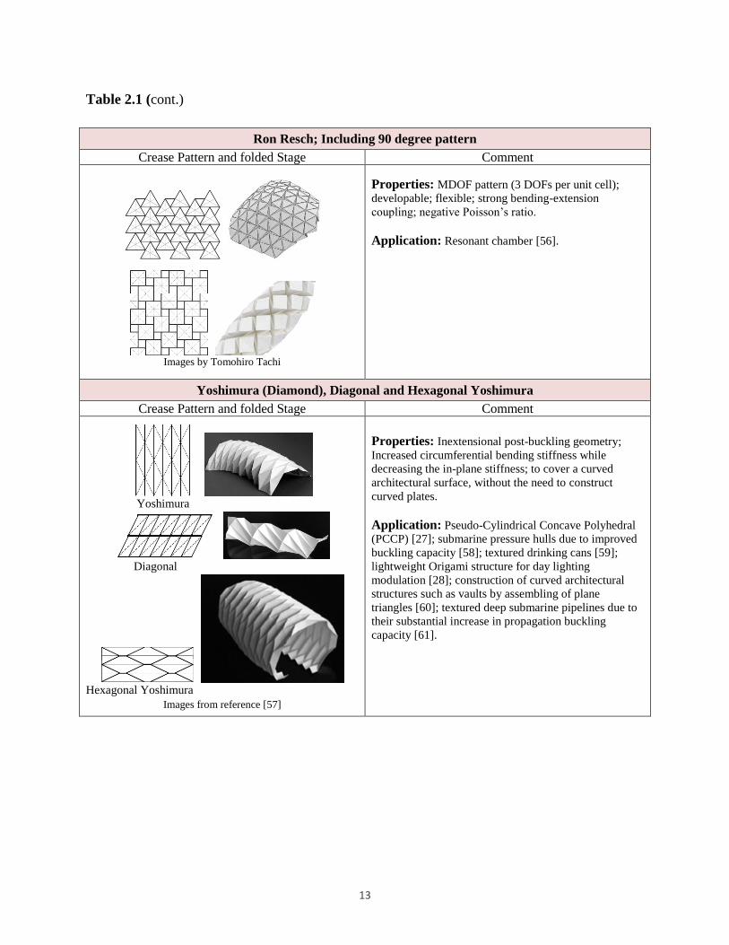
Table 2.1 (cont.)
Ron Resch; Including 90 degree pattern
Crease Pattern and folded Stage Comment
Images by Tomohiro Tachi
Properties: MDOF pattern (3 DOFs per unit cell);
developable; flexible; strong bending-extension
coupling; negative Poisson’s ratio.
Application: Resonant chamber [56].
Yoshimura (Diamond), Diagonal and Hexagonal Yoshimura
Crease Pattern and folded Stage Comment
Yoshimura
Diagonal
Hexagonal Yoshimura
Images from reference [57]
Properties: Inextensional post-buckling geometry;
Increased circumferential bending stiffness while
decreasing the in-plane stiffness; to cover a curved
architectural surface, without the need to construct
curved plates.
Application: Pseudo-Cylindrical Concave Polyhedral
(PCCP) [27]; submarine pressure hulls due to improved
buckling capacity [58]; textured drinking cans [59];
lightweight Origami structure for day lighting
modulation [28]; construction of curved architectural
structures such as vaults by assembling of plane
triangles [60]; textured deep submarine pipelines due to
their substantial increase in propagation buckling
capacity [61].

14
3 Miura- and Eggbox-inspired Cellular Folded
Materials: Synthesis, Analysis and Mechanical
Properties
Abstract
Miura-ori is a classic origami pattern with outstanding mechanical properties which has
received considerable interest in the literature. Similarly to Miura-ori, a regular Eggbox
folded sheet includes parallelogram facets which are connected along fold lines.
However, Eggbox sheets cannot be folded from a flat sheet of material, and contrary to
Miura-ori, there are fewer studies available on Eggbox folded sheet material. By
employing both analytical and numerical models, we review and study the key in-plane
mechanical properties of Miura-ori and Eggbox sheets, and present cellular folded
metamaterials containing Miura-ori and Eggbox cells. The entire structure of the folded
materials is a one-degree of freedom (DOF) mechanism system and, similarly to Eggbox
sheets, the materials composed of layers of Eggbox folded sheets are bi-directionally flat-
foldable, resulting in a material flexible in those directions, but stiff in the third direction.
Moreover, a framework is provided to obtain the Poisson’s ratio of both Miura-ori and
Eggbox sheets. Apart from further investigation of the in-plane Poisson’s ratios of these
folded sheets, the framework can be employed to obtain the in-plane Poisson’s ratios of
similar, but more complex folded sheets for which analytical models are not available.
Keywords: Miura-ori, Eggbox, rigid origami, metamaterial, cellular materials, auxetic materials,
Poisson’s ratio.

15
3.1 Introduction
Although mostly renowned for its visual appeal, origami, the Japanese art of paper folding has
been a source of inspiration for designing cellular foldable materials [62, 63, 64, 15, 10, 65] and
responsive materials and structures [66, 67], among many other applications. In this regard,
Miura-ori, a classic origami folding pattern whose regular form constitutes four parallelogram
facets linked via fold lines (Figure 3.1), has been employed for a wide range of applications
spanning from folding of maps [48], folded-core cellular sandwich panels [68, 16] to the
technologies such as deployable solar arrays [48, 24] and cellular materials and structures [10,
62]. Miura-ori can be folded from a flat sheet of material (i.e., a developable pattern).
Folds and corrugations are also present in natural systems (Figure 3.2), at various scales, from
protein ribbons and DNA to tree leaves and insect wings [2]- in these systems, controlled folding
and unfolding is used to improve functional and (or) mechanical properties. For instance, folding
patterns in insect wings include four panels rotating around four fold-lines intersecting at a point
which is similar to a degree-four origami unit cell and, more specifically, to a Miura-ori cell [69].
Leaves of hornbeam (Carpinus betulus) and common beech (Fagus sylvaticus) have similar
mechanism and folding pattern to that of Miura-ori [70] (Figure 3.2). In addition, a herringbone
pattern forms due to axial compression of a planar stiff thin elastic film at the top of a soft
substrate [71, 72, 73] which corresponds to the minimum energy configuration [74]. The pattern
naturally arises in embryonic intestine as well [75, 76].
Figure 3.1: Illustration of 4 by 3 sheets of Miura-ori and Eggbox (m1=4, m2=3): (a) Miura-ori.
(b) Eggbox.
(a) (b)

16
Observing patterns similar to Miura-ori in biological systems has opened up a research path to
discover associated mechanical, physical and mathematical properties [10, 39, 77]. Some of the
most interesting properties of folded sheet material and structures arise basically due to their
folding geometry. Miura-ori, for most ranges of geometry, is an auxetic material with a negative
in-plane Poisson’s ratio, whereas under bending the sheet exhibits positive Poisson’s ratio, i.e.,
the in-plane and out-of-plane Poisson’s ratio of the sheet are of opposite signs [10, 39, 78].
Figure 3.2: Herringbone pattern in natural systems. (a) Common beech [79]. (b) Hornbeam
[80]. (c) Insect wing [69]. (d) Pattern formed by biaxial compression of a thin film at the top of a
soft substrate [71]. (e) Natural pattern in turkey embryo [75].
Knowing that the Poisson’s ratio of a partially folded Miura-ori sheet is not dependent on the
height of the sheet, and that it is only a function of an angle in the horizontal plane, Schenk and
Guest [10] introduced metamaterials by stacking Miura-ori sheets with different unit cell
geometries while preserving the capability of folding and unfolding. Wei et al. [39] also studied
the in-plane stretching and out-of-plane bending responses of the Miura-ori unit cell.
Eggbox is a bi-directionally flat-foldable pattern. It has been introduced as “expansible surface
structure” by Brunner [52]. The sheet can be made by cutting Miura-ori crease pattern along the
zigzags, and joining the strips with special alignment. Hence, a regular Eggbox sheet includes
parallelogram facets which are connected along fold lines (Figure 3.1). The pattern cannot be
folded from a flat sheet of material. Also, experimental tests [23] show that the sheet exhibits
positive and negative Poisson’s ratio under stretching and bending, respectively. Similarly to
Miura-ori the in-plane and out-of-plane Poisson’s ratios of Eggbox sheet are of opposite signs
which is a remarkable characteristic of this folded sheet material [23].
Tachi and Miura described cellular materials [62] composed of Miura-base tubes [81] with
(a) (b) (c) (d) (e)

17
rhombus cross sections. The tube unit cell, shown in Figure 3.3(a), includes both Miura-ori and
Eggbox cells overlapping by two parallelogram facets. By defining the geometry of Miura-ori
and Eggbox cell in relation to an associated tube cell, we can relate the geometric parameters of
Miura-ori to those of Eggbox as shown in Figure 3.3(a). The tubes assembled in various ways
(e.g., side by side, interleaving etc.) can form the structure of the cellular materials. Special
arrangements of Miura-ori and BCH2 (Basic Cell with Holes in which a unit cell includes 2 large
and 4 small parallelogram facets) [65] tubes form Eggbox surfaces (see Figure 3.4). Hence,
similarly to Eggbox sheets, the materials shown in Figure 3.4 are bi-directionally flat-foldable,
and the materials fabricated with those geometries are soft in two directions and stiff in the third
orthogonal direction.
ea a , eb b , 1 1e , ew l , e , e
Figure 3.3: (a) Tube unit cell with a rhombus cross section decomposed into Miura-ori and Egg-
box cells. The parameters shown in the figure are defined in the Sections on Miura-ori and
Eggbox. (b) A BCH2-based tube forming two different scales Eggbox surfaces at the sides.
In this study, we provide a general overview of the numerical modeling of origami-inspired
structures, where the emphasis is placed on the bar framework approach available in the
literature. Then, the key mechanical properties of Miura-ori and Eggbox patterns are reviewed
and studied and, in this regard, the analytical models for the in-plane stiffness of Miura-ori
available in the literature [39] are modified, and the in-plane Poisson’s ratios and rigidities of
Eggbox are derived. Moreover, a framework is provided to obtain the Poisson’s ratio of both
(a) (b)

18
Miura-ori and Eggbox sheets computationally, using the bar-framework origami structural
modeling approach proposed by Schenk and Guest [23]. Apart from further investigation of the
in-plane Poisson’s ratios of Miura-ori and Eggbox sheets, the framework can be employed to
obtain the Poisson’s ratios of folded sheets with similar kinematics for which analytical models
are not available. Finally, we introduce and describe folded one-DOF mechanism metamaterials
including both Miura-ori and Eggbox cells.
Figure 3.4: Tubular materials forming Eggbox surfaces. (a) A tubular material decomposed to
layers of Eggbox sheets. (b) A novel material created with special assembly of BCH2 sheets
resulting in Eggbox surfaces parallel to the horizontal plane.
3.2 Numerical Modeling of Origami-like Structures
In a folded paper, bending occurs along the fold lines, and the paper has no bending stiffness.
Therefore, it can be approximated either using rigid plates hinged together along the fold lines or
using membrane elements with high stretching stiffness and no bending stiffness. Another
modeling scheme is simulation of origami using pin-jointed truss framework in which the fold-
lines and vertices are modeled using rigid bar elements and perfect hinges, respectively.
Two types of analysis in origami structures are of interest: kinematic analysis and stiffness
analysis. In general, depending on the application of origami, modeling and analysis methods can
be chosen. For example, for kinematic analysis a rigid bar-framework approach and tracking the
null space of the compatibility matrix can be used [23] or the folded sheet can be modeled using
triangular finite element plates [25]. In addition, rigid origami simulation by properly
constraining every vertex has been introduced by Tachi [34]. Balkcom also applied the
(a) (b)

19
mechanism theory for the kinematic analysis [82].
After reaching the mechanism to the desired folded state, to capture the structural properties of a
folded shell system, a stiffness analysis can be carried out and structural modeling can be
performed using a Finite Element Analysis. Depending on the application, either a bar-
framework origami modeling approach or a modeling scheme using nonlinear shell elements
[49] can be used at this stage. The next section includes more details on Schenk and Guest’s bar
framework modeling approach [23] used in current study.
3.2.1 Bar-framework approach
To investigate the effect of geometry on the global behavior of the folded sheet, Schenk and
Guest [23] used a bar framework for modeling of partially folded shell structures. In their
modeling, fold lines and vertices are modeled with bars and frictionless joints, respectively
(Figure 3.5(a)). To stabilize each facet and to model the bending of the facets for stiffness
analysis, the facets are triangulated, and diagonal members are added to each facet (Figure
3.5(a)). In this way, this model considers the bending of the facets and the effect of out-of-plane
kinematics of the sheets, and therefore is not restricted to rigid origami. In a bar-framework
approach the compatibility is to relate the nodal displacements d to the bar extensions e via
compatibility matrix C as follows
Cd e (3.1)
From the relation above, the null space of the compatibility matrix provides the nodal
displacements which do not extend the bars. Additionally, for rigid origami we need to prevent
the bending of the facets. This can be done by adding an angular constraint to the compatibility
matrix. The angular constraint F can be written in terms of the dihedral fold angle between two
facets.
sin( ) sin( ( ))F P (3.2)
where is the dihedral fold angle between two adjoining facets; P is the nodal coordinates of
two facets. By means of vector products, the angle can be obtained. Hence, the change in the

20
dihedral angle is equal to
1
cos( )i
i
Fd dp
p
J d (3.3)
In the above expression, J is the Jacobian of the angular constraint; idp are the nodal coordinates
of joint i. The Jacobian of the angular constraint can be formed for each triangulated facet, and
can be augmented to the compatibility matrix. Hence,
d
eCd (3.4)
in which
facet
CC
J (3.5)
The null space of the above equations provides the solutions that neither extends the bars nor
bends the triangulated facets, i.e., a rigid origami model. Also, the number of internal
infinitesimal mechanisms can be calculated from
3 ( ) 6m j rank C (3.6)
For a modal analysis and also analysis of a folded shell structure subjected to external loads, we
need to have a stiffness formulation. For a bar framework, the stiffness matrix is obtained as
follows
T
barK C G C (3.7)
In Figure 3.5(a), Kfacet and Kfold are rotational stiffness of the facets and folds, respectively. The
equation above can be extended to model the bending of the facets and the fold-lines. Hence, the
stiffness matrix of the system can be obtained from the following expression
0 0
0 0
0 0
T
bar
facet facet facet
fold fold fold
G
G
G
C C
K J J
J J
(3.8)

21
Therefore, for the analysis of the system subjected to the external forces f, we have
Kd f (3.9)
where d is the vector of nodal displacements.
For the stiffness analysis, and to remove the stretching of the panels, we consider a very large
axial stiffness for the bars. The eigenvalue analyses have been done for a wide range of material
properties by changing the ratio of the Kfacet/Kfold.
3.3 Mechanical Properties of Miura-ori and Eggbox Folded Sheet Materials
3.3.1 Miura-ori pattern
The geometry of Miura-ori can be described in various ways. Schenk and Guest [10] defined the
geometry using the angles between the facets and horizontal and vertical planes, whereas Wei et
al. [39] established the geometry based on the dihedral angles between two adjoining facets (see
Section 3.8). However, since the system has only one independent DOF, all these angles are
related. The equations relating the angles defining the geometry of Miura-ori are given by
Schenk and Guest [10]. The geometric parameters of Miura-ori used in current study are shown
in Figure 3.5(b). From the geometry of the unit cell, we have
2 sinw b cos
2cos
a
l sin sinh a (3.10)
Also, the expression relating the angle and the fold angle is given by
tan cos tan (3.11)

22
Figure 3.5: (a) Illustration of the bar framework approach to model folded shell
structures. Fold lines and vertices are replaced with the bars and hinges, respectively. (b)
Geometry of Miura-ori unit cell.
3.3.1.1 Stiffness analysis of Miura-based folded Materials
The results of the stiffness analysis is shown in Figure 3.6 for a Miura-ori 4x4 sheet with facet
angle 60 degrees, a=b=1 and 55 for varying Kfacet/Kfold. Modal shapes for the first lowest
eigen-values of the sheet show that for the large values of Kfacet/Kfold, the first softest eigen-mode
is representing a rigid origami behavior in which the facets do not bend and the bending happens
only around the fold-lines. For the smallest values of Kfacet/Kfold the twisting mode is the
predominant behavior of a Miura-ori sheet. Miura-ori sheet folded from a printing paper exhibits
a saddle shape under bending [23]. As shown in Figure 3.6, the second softest eigen-mode for
the values of Kfacet/Kfold around one (i.e., for the paper material) is a saddle shape which further
confirms the accuracy of the analysis results.
Moreover, the results of the stiffness analysis is illustrated in Figure 3.7 for a sample stacked
Miura. The geometry of the Miura-ori sheets in Figure 3.7 has been chosen according to
reference [10], so that the whole system can fold and unfold freely with the same kinematics.
The result of the eigenvalue analysis also show that the softest eigen-mode of the system is the
rigid origami behavior of the sample stacked Miura-ori for the large values of Kfacet/Kfold. This
analysis further verifies the capability of the bar-framework approach for the stiffness analysis of
complex SDOF system.
(a) (b)
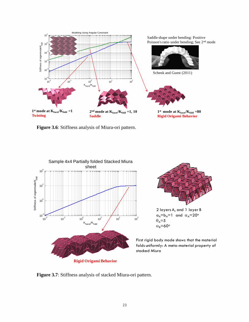
23
Figure 3.6: Stiffness analysis of Miura-ori pattern.
Figure 3.7: Stiffness analysis of stacked Miura-ori pattern.
Schenk and Guest (2011)
Saddle shape under bending: Positive
Poisson's ratio under bending; See 2nd mode
10-2
10-1
100
101
102
10-4
10-3
10-2
10-1
100
101
Kfacet
/Kfold
Stiff
ness o
f eig
enm
ode/K
fold
Modeling Using Angular Constraint
1st mode at Kfacet/Kfold =1
Twisting2nd mode at Kfacet/Kfold =1, 10
Saddle
1st mode at Kfacet/Kfold =80
Rigid Origami Behavior
Rigid Origami Behavior
10-2
10-1
100
101
102
103
10-2
100
102
104
Kfacet
/Kfold
Stiff
ness o
f eig
enm
ode/K
fold
Theta = 5o
First rigid body mode shows that the material
folds uniformly: A meta-material property of
stacked Miura
2 layers A, and 1 layer B
aA=bA=1 and A=20o
A=5
B=60o
Sample 4x4 Partially folded Stacked Miura
sheet

24
3.3.1.2 In-plane response of Miura-ori sheet
In-plane Poisson’s ratio of Miura-ori
The Poisson’s ratio of a (m1 by m2) Miura-ori sheet, shown in Figure 3.1(a), is as follows (see
reference [65] for details)
2
2 1
2
1
2 cos costan
2 cos cosWL e e
m
m
(3.12)
in which, /a b . Therefore, for a Miura-ori sheet, for large number of rows (i.e., 1m ),
Poisson’s ratio considering the end-to-end dimension, e e , approaches the corresponding value
when considering the projected length of the zigzag strips, z (i.e.,2tan ). Notice that even for
a Miura-ori cell in which m1=1, for some ranges of geometric parameters, the Poisson’s ratio
considering the end-to-end dimensions can be positive.
In-plane stiffness of Miura-ori: Kx and Ky
To obtain the in-plane rigidities, we define the unit cell based on parameters similar to those
given in reference [39] (see Section 3.8). The in-plane stretching stiffness of a system in a given
direction (e.g., Kx, Ky) is obtained by taking the derivative of the corresponding force with
respect to the length parameter in that direction [83]. Accordingly, the in-plane stretching
stiffness in the x direction is given by
1 10 0
1
1
x xx
df df dK
d d d
l l (3.13)
in which 01 is the initial dihedral angle at unreformed state.
2 2 2 2
2 1/2 2 2 2 21 3
2 2
(1 ) cos 8 cos4
(1 ) cos sin sin 4 cos 41 1
x
a b aK k
a a all l
(3.14)
where k is the rotational hinge spring constant per unit length. The second term within brackets

25
is missing in reference [39]. The contour plot of the ratio of Kx/k is shown in Figure 3.8 for a
Miura-ori unit cell with a=b=1, in terms of the facet angle and fold angle 1 .
Similarly, the stretching stiffness in the y direction is obtained as follows
0
010 10
1
1
y y
y
ddf dfK
dw d dw
(3.15)
2 2 2
2 2 2 2 21
(1 ) cos 22
(1 ) sin cos( / 2) 4 siny
a bK k
b b w
(3.16)
The contour plot of the ratio of Ky/k is also shown in Figure 3.9 for a Miura-ori unit cell with
a=b=1, in terms of the facet and fold angles and 1 , respectively. Comparison of the two plots
in Figure 3.8 (and Figure 3.9) shows that in-plane stiffness values from reference [39] are less
stiff than their corresponding values obtained from the modified equations.
Figure 3.8: Kx/k for a Miura-ori unit cell with a=b=1: (a) Wei et al.’s equation [39]. (b)
modified equation (present work).
10
10
10
10
10
20
20
20
20
20
20
5050
50
50
5050
50
50
200200
20
0
20
0
200200
200
20
020
0
10001000
1000
10
00
10
00
1000 1000 10
00
10
00
10
00
[Degree]
1 [
Degre
e]
Kx/k [1/length unit]
20 40 60 80
20
40
60
80
100
120
140
160
180
10
10
10
20
20
20
20
50
50
50
50
50
20
0
20
0
200
200
20
0
200200
1000
10
00
10001000
10
00
10
00
10001000
10000
10
000
1000010000
10
000
10
000
10000 10000
[Degree]
1 [
Degre
e]
Kx/k [1/length unit]
20 40 60 80
20
40
60
80
100
120
140
160
180(a) (b)

26
Figure 3.9: Ky/k for a Miura-ori unit cell with a=b=1: (a) Wei et al.’s equation [39]. (b)
Modified equation (present work).
Unlike the expressions given in reference [39], the modified relations for the planar rigidities
(i.e., Kx/k and Ky/k) are not dimensionless, and thus Kx and Ky have dimension of the in-plane
stretching stiffness, which agrees with classical references in structural analysis, e.g. [83].
3.3.2 Eggbox pattern
3.3.2.1 Geometry of Eggbox
The geometric parameters of Eggbox used in current study are shown in Figure 3.10.
From the geometry of the unit cell:
2 sine e eb l , 2 sine e ew a , cos cose e e e eh a b (3.17)
in which 0 ,e e . Another useful expression is given as
cos cos cose e (3.18)
where e and e are the angles between the z’-axis and the edges ae and be, respectively. Also,
1e and 2e are the dihedral angles between two adjacent facets along the edges ae and be,
respectively (Figure 3.10), and are given by
3
3
7
7
7
7
20
20
2020
20
10
010
0
100 100100
10
00
10
00
10
00 1000 1000
1000
[Degree]
1 [
Degre
e]
Ky/k [1/length unit]
20 40 60 80
20
40
60
80
100
120
140
160
180
3
3
7
7
7
20
20
20
20
10
0
100
100 100
10
00
10
00
1000 10001000
10
000
10
000
10000 10000 10000
[Degree]
1 [
Degre
e]
Ky/k [1/length unit]
20 40 60 80
20
40
60
80
100
120
140
160
180(a) (b)

27
1
1
sin2sin
sin
ee
(3.19)
1
2
sin2sin
sin
ee
(3.20)
Figure 3.10: Geometry of Eggbox unit cell. The geometry of a regular Eggbox sheet can
be parameterized by the geometry of a parallelogram facet (ae, be and ), and one fold
angle, e.g. e [0, ] which is the angle between fold lines be and the z’-axis. Other
important angles in the figure are angle between the fold lines ae and the z’-axis, i.e., e
[0, ]; and dihedral fold angles between parallelogram facets e [0, ] and e [0,
], joining along fold lines ae and be, respectively.
3.3.2.2 Stiffness analysis of Eggbox sheet
The results of the stiffness analysis are presented in Figure 3.11 for an Eggbox 4x4 sheet with
facet angle 60 degrees, ae=be=1 and 45e for a wide range of Kfacet/Kfold. Modal shapes for the
first lowest eigen-values of the sheet show that for large values of Kfacet/Kfold, the first softest
eigen-mode is representing a rigid origami behavior, which agrees with our expectation. For
small values of Kfacet/Kfold twisting mode is the predominant behavior of an Eggbox sheet. The
Eggbox sheet folded from a printing paper exhibits a spherical shape under bending [23]. As
shown in Figure 3.11, the second softest eigen-mode for the values of Kfacet/Kfold around one (i.e.,
for paper material) is a spherical shape which further confirms the accuracy of the analysis
results.

28
Figure 3.11: Stiffness analysis of Eggbox pattern.
3.3.2.3 In-plane response of Eggbox sheet
In-plane Poisson’s ratio
In-plane Poisson’s ratio of Eggbox sheet is given by
2
2
tan
tan
e
e e
e
e e e
w
w e e e
w d
dw
ll
ll
(3.21)
From the above expression, the Poisson’s ratio of Eggbox is always positive, i.e. [0, )e ew
l ,
which was also quantified in the literature based on the angle e and the facet acute angle [23].
However, knowing that the Poisson’s ratio is only a function of the angles between the z’-axis
and the edges ae and be is insightful for creating foldable materials containing layers of Eggbox
sheets with different geometries as presented in Section 3.7. The in-plane Poisson’s ratio of
Eggbox versus e for different values of the acute angle is presented in Figure 3.15(b).
1st mode
Twisting2nd mode
Spherical
1st mode
Rigid Origami Behavior
10-2
10-1
100
101
102
10-4
10-3
10-2
10-1
100
101
Kfacet
/Kfold
Stiff
ness o
f eig
enm
ode/K
fold
Modeling Using Angular Constraint
Schenk and Guest (2011)
Spherical shape under bending: Negative
Poisson's ratio under bending; See 2nd mode

29
In-plane stiffness: Kx’ and Ky’
Considering that the facets are rigid and are bonded via elastic torsional hinges at fold lines, we
obtain the in-plane rigidities of Eggbox unit cell in the x’ and y’ directions (see Section 3.8) as
follows
2 2 2
1
2 2 2 2 21 1
(1 ) cos4 1
sin cos( / 2) (1 ) 4 sin
e e ex
e e e ee
a bkK
b b
l
(3.22)
2 2 2
2
2 2 2 2 22 2
cos (1 )4 1
sin cos( / 2) (1 ) 4 sin
e e ey
e e e e e
a bkK
a a w
(3.23)
in which 1 1sin sin / 2e e and 2 2sin sin / 2e e .
For the case of ea a , eb b , 1 1e and ew l , shown in Figure 3.3(a), from Equations (3.16)
and (3.22), the in-plane stiffness of Miura-ori cell in the y direction (Ky), is equal to the in-plane
stiffness of Eggbox cell in the x’ direction (Kx’). The contour plot of the stiffness ratio in the x’
direction (Kx’/k) is shown in Figure 3.12 for an Eggbox unit cell with ae=be=1, in terms of the
facet angle and fold angle 1e .
Figure 3.12: In-plane stretching stiffness Kx’/k of Eggbox unit cell with a=b=1.
3
3
7
7
7
20
20
20
20
10
0
100
100 100
10
00
10
00
1000 10001000
10
000
10
000
10000 10000 10000
[Degree]
1e [
Degre
e]
Kx/k [1/length unit]
20 40 60 80
20
40
60
80
100
120
140
160
180

30
3.4 A Framework to Obtain Poisson’s Ratio Computationally
Instantaneous Poisson’s ratio of Miura-ori is computed numerically in this section. A Miura-ori
unit cell is modeled using the bar framework approach, and the Poisson’s ratio is calculated for
changing and . For the analysis under the external applied loads, we need to remove the rigid
body motions of the system while keeping the planar motion by applying appropriate constraints.
The simulation set up is illustrated in Figure 3.13(a) in which yellow nodes are constrained to
remain in the horizontal (xy) plane (i.e., only displacements in the z direction are constrained,
and the system moves freely in the xy plane), and the blue node is constrained for all
displacements. External force is also applied in the x direction as shown in Figure 3.13(a).
Moreover, to ensure the rigid origami behavior for obtaining the planar Poisson’s ratio, the value
of Kfacet/Kfold must be large enough, and the axial stiffness of the bars, Kbar, is required to be
sufficiently large to prevent the extension of the bars. For this example, we choose Kbar=109 and
Kfacet/Kfold=103 - eigen-value analysis of the system confirms that using these values, the rigid
origami behavior is obtained for the Miura-ori unit cell considered in this section (Figure
3.14(a)). Figure 3.15(a) shows Poisson’s ratio obtained from the simulation matches well with
the analytical model.
A similar approach to the one described for Miura-ori has been used to obtain the instantaneous
Poisson’s ratio of Eggbox. The simulation set up is illustrated in Figure 3.13(b) in which yellow
nodes are constrained to move freely in the horizontal (xy) plane (i.e., only displacements in the z
direction are constrained), and the blue node is constrained for x and y displacements, and moves
freely in z direction. External force is also applied in the x direction as shown in Figure 3.13(b).
The mode shapes showing the rigid origami behavior are shown in Figure 3.14(b). Figure 3.15(b)
shows that Poisson’s ratio obtained from the simulation matches reasonably well the analytical
model.

31
Figure 3.13: Simulation set up to compute Poisson’s ratio numerically. (a) Miura-ori. (b)
Eggbox.
Figure 3.14: First mode illustrating rigid origami behavior: (a) Miura-ori. (b) Eggbox
unit cell.
Figure 3.15: Poisson’s ratio computed numerically: (a) Miura-ori. (b) Eggbox unit cell.
3.5 Metamaterials Composed of Miura-ori and Eggbox Cells
From expression 24, the Poisson’s ratio of a regular Eggbox sheet is a function of the angles e
y
xz
0 10 20 30 40 50 60 70 80 90-5
-4
-3
-2
-1
0
[Degree]
( w
l) Pro
j [-]
=45
=60
=65
=70
=75
0 10 20 30 40 50 600
1
2
3
4
5
e [Degree]
(w
l)e [
-]
=45
=60
=65
=70
=75
(a)
(a) (b)
(b)
(a) (b)

32
and e (see Figure 3.10). Layers of Eggbox sheets with the same Poisson’s ratio can be attached
along the joining fold lines resulting in a bi-directionally flat-foldable material (Figure 3.4). A
similar tubular material composed of Miura-based tubes with identical parallelogram facets has
been described by Tachi [62]. The cross section of the tube described by Tachi has identical
edges (Figure 3.16(a)). In general, Miura-ori tube is a special case of stacking of Miura-ori sheets
[10] in which the angle has different signs for the sheets A and B bonded together along the
joining fold lines, i.e. [ / 2,0]A and [0, / 2]B . Meeting the stacking conditions results in
a tube cell with the kite-shape cross section shown in Figure 3.16(b) which is generally flat-
foldable in one direction.
Figure 3.16: (a) Tube cell with rhombus cross section. (b) General tube cell geometry,
for the kite-shape cross section, 1 2A Aa a and 1 2B Ba a .
For two layers of Miura-ori cells (i.e., layers A and B), from the conditions for stacking of
Miura-ori [10] we have
1 2 1 2cos cosA A A B B Ba a a a (3.24)
where 1Aa , 2 Aa , 1Ba and 2Ba are shown in Figure 3.16(b). Also, from the geometry of Miura cell
we have
coscos
cos
(3.25)
(a) (b)

33
Combining two above equations results in
1 2 1 2cos cosA A A B B Ba a a a (3.26)
From the above expression, for the special case of A B , we need to have
1 2 1 2A A B Ba a a a (3.27)
To meet the above equation, we can have
1 2A Ba a and 2 1A Ba a (3.28)
Hence, for the special case of identical acute angles at the top and bottom cells (i.e., A B ), we
can have bi-directionally flat-foldable tubes with parallelogram cross sections (Figure 3.17). In
the following, we describe tubular folded materials composed of tubes with parallelogram cross
sections. As shown in Figure 3.18, with special alignments of tube cells and tessellation and/or
combinations of tessellations of corresponding units, we can produce various cellular
metamaterials. Tessellation of the alignment of the cells, shown in Figure 3.18(a), can result in
materials with either Miura or Eggbox surfaces (see Figure 3.19). Figure 3.18(e) presents a
cellular metamaterial with Miura-ori and Eggbox surfaces parallel to the xz and yz planes,
respectively. Therefore, the material is auxetic in the planes parallel to xz plane, and expanding
the material in the z direction results in the expansion and contraction of the material in the x and
y directions, respectively.
3.6 Non-developable Zigzag-base Sheets and Zigzag-base Tubes
In this Section, we use the concept of the Poisson’s ratio of a zigzag strip introduced in reference
[65] (see Sections 4.2 of the current dissertation), to design non-developable zigzag-base patterns
(see Figure 3.20) as well as load-carrying zigzag-base tubes (see Figure 3.21 and Figure 3.22).
To construct these structures, zigzag strips with identical kinematics are connected. Figure 3.20
presents non-developable zigzag-base patterns. The patterns shown in the figure are designed so
that, in their fully deployed configurations, the Miura-ori rows in the middle (dark pink) are flat,
while the outer rows remain non-flat. Using the kinematics of a zigzag strip, we can design

34
various configurations of non-developable zigzag-base patterns in which the geometry can differ
from one zigzag to the other one and even from one V-shape (see Sections 4.2) to the other one
while keeping the kinematics identical.
Figure 3.21 and Figure 3.22 show load-carrying zigzag-base tubes. The structures are flat-
foldable in one direction and can carry load in their fully deployed configurations.
3.7 Concluding Remarks
Eggbox is a non-developable folded sheet. The sheet is a one-DOF mechanism system and bi-
directionally flat-foldable material. Its structure can appear into Miura-inspired tubular materials
when assembled in a special way. A sample novel bi-directionally flat-foldable material is shown
in Figure 3.4(b) which contains layers of two different scales Eggbox sheets. Unlike Miura-ori,
there is limited research available in the literature on Eggbox folded sheet.
Figure 3.17: Miura-ori based tube with parallelogram cross section. (a) Unfolded Miura-
ori unit cells with mountain (blue continuous lines) and valley (red dashed lines)
assignments. (b) Partially folded Miura-ori cells constructing the top and bottom of the
tube cell. (c) Tube cell with parallelogram cross section.
In this study, the key mechanical properties of Miura-ori and Eggbox are reviewed and studied
both analytically and numerically. Specifically, the geometric parameters of Miura-ori and
Eggbox are explained in relation to a tube cell with rhombus cross section (see Figure 3.3) which
can be decomposed to Miura-ori and Eggbox cells. In this way, mechanical properties of Eggbox
(a)
(b)
(c)

35
and Miura-ori can be compared appropriately. Furthermore, employing bar-framework numerical
approach, a procedure is described to obtain the Poisson’s ratio of both Miura-ori and Eggbox.
The process can be used to obtain the Poisson’s ratio of similar, but more complex sheets for
which the analytical models are not available. Verifying the analytical models for Poisson’s ratio
numerically, as explained in this work, somehow shows the capability of pin-jointed bar
framework approach for the analysis of folded shell structures subjected to external loads.
Additionally, Miura-based tube with parallelogram cross section is explained (notice that in the
tube shown in Figure 3.17, parallelogram facets of Miura-ori cells are not identical), and the
geometry of one-DOF mechanism cellular metamaterials containing tubes with parallelogram
cross sections is described. The proposed structures are purely geometric. Hence, they can be
applied in a wide range of length-scale from microstructure of materials to deployable structures.
Particularly, possessing one DOF is advantageous to provide low-energy, efficient and
controllable actuation. Hence, making them appropriate as the bases to construct adaptive
structures and materials.
The conditions for stacking Miura-ori sheets with different geometries are described in reference
[10]. However, attaching Eggbox sheets with different geometries, while preserving the
capability of folding and unfolding is not described in the literature. Inspired by tubes with
parallelogram cross sections (Figure 3.17) as well as the fact that the Poisson’s ratio of Eggbox is
only a function of the angles between the edges ae and be and the z’-axis (see Equation (3.21)),
we can design the structure of customizable cellular materials with one-DOF mechanism
containing layers of Eggbox sheets (a sample is shown in Figure 3.23). The material shown in
the figure contains three layers of Eggbox sheets which are attached along the joining fold-lines.
The sheets have different geometries, but the same Poisson’s ratios. Hence, the entire system can
fold and unfold freely.

36
Figure 3.18: (a-d) Sample alignments of tube cells with parallelogram cross sections, and
sample one-DOF mechanism materials made from them. (e-g) Tessellations and/or
combinations of these units results in various configurations of materials.
Figure 3.19: (a) Material with Miura surfaces at the top and bottom. (b) Material with
Eggbox surfaces at the top and bottom. (c) Bi-directionally flat-foldable tubular materials
with parallelogram cross sections decomposed to Eggbox sheets.
z
yx
(a)
(b)
(a)
(b)
(c)
(d)
(e)
(f)
(g)
(c)

37
Figure 3.20: Non-developable zigzag-base patterns constructed from Miura-ori cells with
identical kinematics and different heights of the unit cells (the rule is similar to that used
in the stacking, but the cells possessing different heights are connected side-by-side
instead of stacking).
Figure 3.21: Modified zigzag-base tubes constructed from zigzag strips with identical
kinematics and different heights (in their semi-folded states) and various acute angles of
parallelograms. The presented tubes are flat-foldable in one direction, and they provide a
flat and load carrying surface in their fully deployed configurations.

38
Figure 3.22: A side-by-side assembly of the tubes shown in the figure above. The
structure is flat-foldable in one direction and can carry vertical loads in its deployed
configuration.
Figure 3.23: (a) Sample graded bi-directionally flat-foldable cellular material with one-
DOF mechanism inspired by Miura-based tube with parallelogram cross section. The
sample material includes 3 layers of Eggbox with the same Poisson’s ratio bonded along
joining fold lines. (b, c) Fully folded states in 2 orthogonal directions.
Acknowledgments: I would like to thank Dr. Simon Guest and Dr. Mark Schenk for their
constructive feedback and discussions regarding the bar-framework origami structural
modeling approach and the geometry of Eggbox used in this Chapter.
(a)
(b)
(c)

39
3.8 Supplementary Materials: In-plane Stiffness
3.8.1 Miura-ori
The geometry of Miura-ori unit cell (Figure 3.5(b)) in reference [22] is parametrized based on
the dihedral fold angles between facets as follows
2al 2w b 1tan cos( / 2)h a (3.29)
in which,
1sin sin / 2 and 1/2
2cos 1
(3.30)
By substituting l from Equation (3.29) in Equation (3.14) and for a special case of Miura-ori
unit cell with a=b=leq we have
0 0
2 3 2 2
0 0
2 3
0 1 1
(1 ) cos (1 )4
cos sin sin cos( / 2)x
eq
kK
l (3.31)
By substituting w from Equation (3.29) in equation (3.16) and for a special case of Miura-ori
unit cell with a=b=leq we have
0
2 2 2
0
2 2 2 2
0 1
(1 ) cos2
(1 ) sin cos ( / 2)y
eq
kK
l (3.32)
3.8.2 Eggbox
Potential energy of an Eggbox unit cell subjected to a force in the x’ direction can also be
calculated from the following equation
H U (3.33)
in which, U and are elastic energy and potential of the applied load, respectively and can be
calculated as
0 0
2 2
1 1 2 2( ) ( )e e e e e eU k a b (3.34)

40
1
1 0
1
1
e
e
x e
e
edf d
d
l
(3.35)
where 02e and
01e are the initial dihedral angles at unreformed states. Setting the condition
1/ 0eH , the external force at equilibrium xf can be obtained from
1
1
/
/
ex
ee
dU df
d d
l
(3.36)
where
0 01 1 1 2 2 2 2
1
cos/ 2 ( ) ( )
1 sin sin ( / 2)e e e e e e e
e
dU d k a b
(3.37)
1 1/ sin cos( / 2)ee e ed d b l (3.38)
Substituting the two above equations into xf , we have
0 01 1 2 2 2 2
1
1
cos( ) ( )
1 sin sin ( / 2)2
sin cos( / 2)
ee e e e
e ex
e
a
bkf
(3.39)
Also, xK can be obtained from the following equation
0
1 10 0
11
1
( , )
e e
x x
e
ee
e
x
e
df df dK
d d d
l l
(3.40)
where
0
0 0 01 0
2 2 2 2
1
2 2 2
1 1 1
cos (1 sin sin ( / 2))2 1
sin cos( / 2) (1 sin sin ( / 2))e
e e ex
e e e e
b adf k
d b
(3.41)
1
2 2 2
2
4 sin
e
ee e
d
d b
l l (3.42)
Substituting equations (3.41) and (3.42) into (3.40) we have

41
2 2 2 2
1
2 2 2 2 2 21 1
cos (1 sin sin ( / 2))4 1
sin cos( / 2) (1 sin sin ( / 2)) 4 sin
e e ex
e e ee e
b akK
b b
l
(3.43)
Figure 3.24 shows that increasing the fold length be, i.e. the fold in the x’ direction, makes the
unit cell softer in the x’ direction. Whereas, increasing the fold length ae, increases the ratio of
Kx'/k.
Figure 3.24: Effect of fold lengths on in-plane stretching stiffness Kx’/k of Eggbox unit
cell: Left (ae=1 and be=5); Right (ae=5 and be=1).
Following similar process to the x’ direction, for the y’ direction we have
2 2 2 2
2
2 2 2 2 2 22 2
cos (1 sin sin ( / 2))4 1
sin cos( / 2) (1 sin sin ( / 2)) 4 sin
e e ey
e e e e e
a bkK
a a w
(3.44)
Equation (3.44) is similar to Equation (3.43) where 1, , ,e eeea b l in Equation (3.43) are
substituted with 2, , ,e eeeb a w , respectively.
3
3
3
3
7
7
7
7
20
20
2020
20
10
010
0
100 100 100
10
00
10
00
1000 10001000
10
000
10
000
10
000
10000 10000
[Degree]
1e [
Degre
e]
Kx/k [1/length unit]
20 40 60 80
20
40
60
80
100
120
140
160
180
20
20
10
0
100
100100
10
00
10
00
10001000 1000
10
000
10
000
10000 10000 10000
[Degree]
1e [
Degre
e]
Kx/k [1/length unit]
20 40 60 80
20
40
60
80
100
120
140
160
180

42
4 Unravelling Metamaterial Properties in
Zigzag-base Folded Sheets
This chapter is adapted from an article authored by Eidini and Paulino, published in
Science Advances [65].
Abstract
Creating complex spatial objects from a flat sheet of material using origami folding
techniques has attracted attention in science and engineering. In the present work, we use
the geometric properties of partially folded zigzag strips to better describe the kinematics
of known zigzag/herringbone-base folded sheet metamaterials such as Miura-ori. Inspired
by the kinematics of a one-degree of freedom zigzag strip, we introduce a class of cellular
folded mechanical metamaterials comprising different scales of zigzag strips. This class
of patterns combines origami folding techniques with kirigami. Using analytical and
numerical models, we study the key mechanical properties of the folded materials. We
show that our class of patterns, by expanding on the design space of Miura-ori, is
appropriate for a wide range of applications from mechanical metamaterials to
deployable structures at small and large scales. We further show that, depending on the
geometry, these materials exhibit either negative or positive in-plane Poisson’s ratios. By
introducing a class of zigzag-base materials in the current study, we unify the concept of
in-plane Poisson’s ratio for similar materials in the literature and extend it to the class of
zigzag-base folded sheet materials.
Keywords: origami; auxetic; metamaterial; deployable structures; Miura-ori; soft material;
Herringbone; zigzag; kirigami; Poisson’s ratio.

43
4.1 Introduction
Origami, the art of paper folding, has been a substantial source of inspiration for innovative
design of mechanical metamaterials [10, 50, 39, 40, 62], for which the material properties arise
from their geometry and structural layout. Kirigami is the art of paper cutting and, for
engineering applications, it has been used as combination of origami with cutting patterns to
fabricate complex microstructures through micro-assembly [84], as well as to create 3D core
structures [64, 85, 86, 87]. Furthermore, rigid origami is a subset of origami structures where
rigid panels (facets) are linked through perfect hinges leading to an entirely geometric
mechanism. The mathematical theory of rigid origami has been studied by various researchers
[30, 31, 32, 35, 34]. Based on rigid origami behavior of folding patterns, recent research [10, 39]
has shown that in Miura-ori, metamaterial properties arise due to their folding geometry. Miura-
ori is a classic origami folding pattern and its main constituents are parallelogram facets which
are connected along fold lines. Morphology and/or mechanism similar to that of Miura-ori
naturally arises in insect wings [69], tree leaves [70] and embryonic intestine [75, 76]. Moreover,
it has been reported that a self-organized wrinkling pattern of a planar stiff thin elastic film
connected to a soft substrate subjected to biaxial compression, i.e. a herringbone pattern, is
similar to the Miura-ori [71, 72, 73]; and herringbone pattern corresponds to the minimum
energy configuration [74]. Applications of the Miura-ori pattern range from folding of maps [48]
to the technologies such as deployable solar panels [24], foldcore sandwich panels [16, 68] and
metamaterials [10, 50, 39]. The patterns introduced in this work are herringbone-base patterns,
which are combined with cuts, and shown to possess the remarkable properties of the Miura-ori
pattern.
Motivated by outstanding properties and broad range of applications of the Miura-ori, the present
study starts with raising a question: Can we design patterns aiming at both preserving the
remarkable properties of the Miura-ori and expanding upon its design space? In this regard, upon
closer inspection of the Miura-ori, we associate its kinematics to that of a one-degree of freedom
(DOF) zigzag strip, and we present a technique to create zigzag-base mechanical metamaterials
including various scales of zigzag strips. Through this study, we answer the question
affirmatively.

44
An important material property in the present work is the in-plane Poisson's ratio. It is defined as
the negative ratio of elastic extensional strain in the direction normal to the applied load, to the
axial extensional strain in the direction of the applied load. Most commonly, when a material is
stretched in a given direction it tends to get narrower in the directions perpendicular to the
applied load. However, when stretched, materials with negative in-plane Poisson's ratio or
auxetic materials expand in the direction perpendicular to the applied load. The out-of-plane
bending Poisson’s ratio is defined as the negative ratio of curvatures in two perpendicular
directions. Under bending, anticlastic (saddle-shape) and synclastic (spherical-shape) curvatures
are observed in materials with positive and negative bending Poisson’s ratios, respectively [88,
23]. Based on the theory of elasticity, the Poisson's ratio for a thermodynamically stable isotropic
linear elastic material is bounded between -1 to 0.5 [89]. Contrary to isotropic solids, the value of
Poisson's ratio is unrestricted in an anisotropic elastic material ( ) [90]. Folded sheets
are anisotropic materials in which the deformation happens due to folding and unfolding. Thus,
in folded sheet materials (for instance in most ranges within geometric parameters of the Miura-
ori folding pattern), the Poisson’s ratio can assume values outside the bound for isotropic
materials [10, 39].
4.2 Kinematics of a Folded One-DOF Zigzag Strip
In this section, we look closely at the kinematics of Miura-ori as a zigzag-base folding pattern,
which provides inspiration to create a class of mechanical metamaterials. A regular Miura-ori
sheet contains zigzag strips of parallelogram facets, in which each unit cell can be decomposed
into two V-shapes (Figure 4.1(a)). Each V-shape includes 2 rigid parallelogram facets connected
via a hinge along the joining ridges as shown in Figure 4.1(b). We show that the kinematics of a
properly constrained V-shape, as described in the following, is a function of an angle in the
horizontal xy-plane. The constraints on the V-shape are applied to simulate similar conditions to
those of the V-shapes in Miura-ori sheet, i.e., to create a one-DOF planar mechanism. Hence, to
remove the rigid body motions associated with the translational and rotational DOFs, we
constrain all translational DOFs of the point A and we assume that the edges AB and BC of the
facets move in the xy-plane, and the projected length of the edge AD in the xy-plane remains
along the x-axis (i.e., point D moves in the xz-plane). With this set up, the V-shape has only one
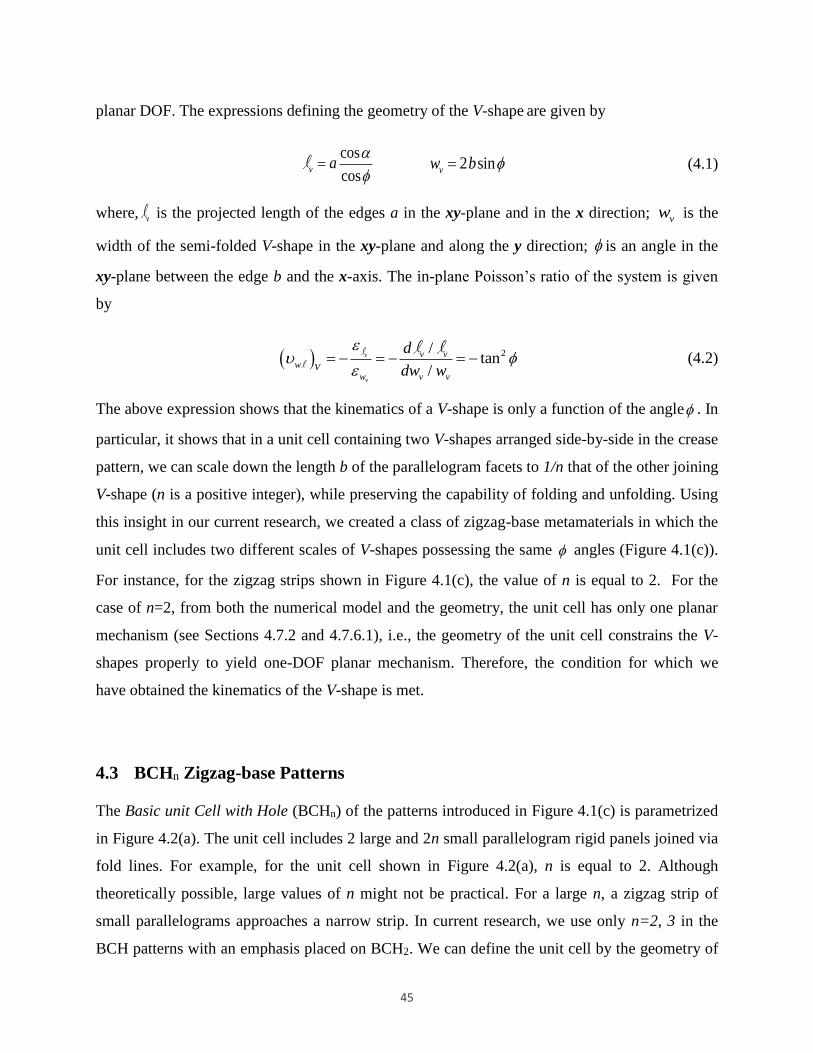
45
planar DOF. The expressions defining the geometry of the V-shape are given by
cos
cosv a
l 2 sinvw b (4.1)
where, vl is the projected length of the edges a in the xy-plane and in the x direction; vw is the
width of the semi-folded V-shape in the xy-plane and along the y direction; is an angle in the
xy-plane between the edge b and the x-axis. The in-plane Poisson’s ratio of the system is given
by
2/tan
/
v
v
v v
w Vw v v
d
dw w
ll
l l (4.2)
The above expression shows that the kinematics of a V-shape is only a function of the angle . In
particular, it shows that in a unit cell containing two V-shapes arranged side-by-side in the crease
pattern, we can scale down the length b of the parallelogram facets to 1/n that of the other joining
V-shape (n is a positive integer), while preserving the capability of folding and unfolding. Using
this insight in our current research, we created a class of zigzag-base metamaterials in which the
unit cell includes two different scales of V-shapes possessing the same angles (Figure 4.1(c)).
For instance, for the zigzag strips shown in Figure 4.1(c), the value of n is equal to 2. For the
case of n=2, from both the numerical model and the geometry, the unit cell has only one planar
mechanism (see Sections 4.7.2 and 4.7.6.1), i.e., the geometry of the unit cell constrains the V-
shapes properly to yield one-DOF planar mechanism. Therefore, the condition for which we
have obtained the kinematics of the V-shape is met.
4.3 BCHn Zigzag-base Patterns
The Basic unit Cell with Hole (BCHn) of the patterns introduced in Figure 4.1(c) is parametrized
in Figure 4.2(a). The unit cell includes 2 large and 2n small parallelogram rigid panels joined via
fold lines. For example, for the unit cell shown in Figure 4.2(a), n is equal to 2. Although
theoretically possible, large values of n might not be practical. For a large n, a zigzag strip of
small parallelograms approaches a narrow strip. In current research, we use only n=2, 3 in the
BCH patterns with an emphasis placed on BCH2. We can define the unit cell by the geometry of

46
the parallelogram facets with sides a and b and acute angle [0, /2], and angle [0, ],
which is half the angle between the edges b1 in the xy-plane. The expressions defining the
geometry of the BCHn are given by
2 sinw b cos
2cos
a
l sin sinh a 1 /b b n (4.3)
Figure 4.1: From Miura-ori to zigzag-base foldable metamaterials possessing different
scales of zigzag strips. (a) A Miura-ori unit cell contains two V-shapes aligned side-by-
side forming one concave valley and three convex mountain folds (or vice versa, if the
unit cell is viewed from the opposite side). (b) Top view of a V-shape fold including two
identical parallelogram facets connected along the ridges with length a. Its geometry can
be defined by the facet parameters a, b, and the angle [0, ]. (c) Two different
scales of V-shapes with the same angle are connected along joining fold lines. The
length b of the parallelogram facets in the left zigzag strip of V-shapes is half that of the
strip on the right in the unit cell shown.
The relationship between the angle and the fold angle is as follows:
tan cos tan (4.4)
The outer dimensions of a sheet made of tessellation of the same BCHn (Figure 4.2(b)) are given
by
(a) (b) (c)

47
2 2 sinW m b 1
cos 1 12 cos cos
cos
nL m a b b
n n
(4.5)
Note that, in the relation given for the length L, the expression within the parentheses presents
the length of the repeating unit cell, and the last term shows the edge effect. The second term
within the parentheses is related to the effect of the holes in the tessellation.
For the case of rigid panels connected via elastic hinges at fold-lines, from the geometry, the
BCH with n=2 has only one independent DOF. In general, the number of DOFs for each unit cell
of BCHn is (2n-3). Using at least two consecutive rows of small parallelograms, instead of one,
in BCHn (see Figure 4.9(b)) decreases the DOFs of the BCH to one irrespective of the number of
n (see Figure 4.10 and Section 4.7.6.1 in supplementary materials for more details). Additionally,
the patterns are all rigid and flat-foldable, and can be folded from a flat sheet of material, i.e.,
they are developable. In Figure 4.3, a few configurations of the patterns are presented.
Figure 4.2: Geometry of BCHn pattern. (a) Geometry of the unit cell. The geometry of a
sheet of BCHn can be parameterized by the geometry of a parallelogram facet (a, b and
), half number of small parallelogram facets (n) and fold angle [0, ] which is the
angle between fold lines b and the x-axis. Other important angles in the figure are fold
angle between the facets and the xy-plane, i.e., [0, /2]; angle between the fold lines
a and the x-axis, i.e., [0, ]; and dihedral fold angles between parallelograms,
[0, ] and [0, ], joined along fold lines a and b, respectively. (b) A sheet of BCH2
with m1=2, m2=3 and outer dimensions of L and W.
(a) (b)

48
4.4 Mechanical Properties of BCHn Patterns
In the present research, we obtain the in-plane Poisson’s ratio in two different ways:
• Considering the projected lengths of the zigzag strips.
• Considering the end-to-end dimensions of a sheet.
Note that while the first approach is valuable to provide insight on the kinematics of a zigzag-
base folded sheet such as the Miura-ori and BCH2, the latter definition can also be relevant
depending on the application. To place emphasis on these two important concepts in relation to
the folded sheet materials introduced in this work, we designate the value obtained by the first
approach as z and the latter as e e , where the indices z and e-e stand for zigzag and end-to-end,
respectively (see Figure 4.4(a) and Figure 4.11). In this regard, for the sheet of BCH2 shown in
Figure 4.2(b), l and L are used to obtain z and e e , respectively. Notice that l for a sheet is the
sum of the projected lengths of the zigzag strips in the xy-plane and parallel to the x-axis, and for
a sheet made of tessellation of identical BCH2 is equal to m1 times that of a unit cell (Figure
4.4(a)). Also, L is the end-to-end dimension of the sheet as shown in Figure 4.2(b). Furthermore,
in both approaches W=w. Hence, z of the sheet is given in the following which is equal to the
kinematics of a V-shape described in the previous sections.
2/tan
/w z
w
d
dw w
l
ll l
(4.6)
Accordingly, BCH2 and all other combined patterns of BCH with one-DOF planar mechanism
(e.g., patterns shown in Figure 4.3) have z equal to 2tan (i.e., z of a Miura-ori sheet with the
same fold angle [10, 39] - see Figure 4.4 (a) and (b)). We emphasize that the in-plane Poisson’s
ratio, obtained by considering the projected lengths of the zigzag strips in the patterns, also
provides insight that the components with identical z can be connected to get a material which
can fold and unfold freely (e.g., see Figure 4.3(f)). Additionally, using this insight, we can create
numerous configurations of metamaterials (see Section 4.7.1 in supplementary materials for
more details). For the sheets made of tessellation of the same BCHn (e.g., Figure 4.3(a)), e e is
given by

49
2
2
2
/ cos costan
/ cos cos
LWL e e
W
dL L
dW W
(4.7)
in which
1
1
2
1 1
n m
m n
and
a
b (4.8)
in which n=2 (notice that n=1 gives the relation for the Miura-ori sheet). Considering the end-to-
end dimension, for a unit cell of BCH2 (m1=1), the e e is similar to that of a Miura-ori unit cell
(Figure 4.4(c)) and is given by
2
2
2
2 cos costan
2 cos cosWL e e
(4.9)
Therefore, unlike z which is always negative (Figure 4.4(b)), e e can be positive for some
geometric ranges (Figure 4.4 (c) and (d)). Moreover, z is only a function of the angle , but e e
can be dependent on other geometric parameters, i.e., the geometry of the facets (a, b, ),
tessellations (n, m1) and the angle . Notice that Poisson’s ratio considering the end-to-end
dimensions can be positive even for a Miura-ori unit cell (Figure 4.4(c)). Also, note that the shift
from negative to positive Poisson’s ratio in Miura-ori is only the effect of considering the tail
[78], and the difference between two Poisson’s ratios (i.e., z and e e ) vanishes as the length of
the Miura-ori sheet approaches to infinity. However, note that for the BCH patterns with holes,
the transition to positive Poisson’s ratio is mainly the effect of the holes in the sheets, and unlike
the Miura-ori, even for a BCH sheet with an infinite configuration, the difference between these
two approaches (i.e., z and e e ) does not disappear (see Figure 4.5). In this regard, Figure 4.5
presents Poisson’s ratio of a repeating unit cell of BCH2 pattern (within an infinite tessellation)
which corresponds to the following expression.
2
2
2
4 cos costan
4 cos cose e
(4.10)
From the Equation above, e e
for the BCH2 sheet is positive if
24 cos cos . The value
is negative if 24 cos cos .

50
Analogous to Miura-ori sheet [10], similar sheets possessing the same z can be designed to be
stacked and attached together along joining fold lines to form cellular folded metamaterials with
capability of folding freely (Figure 4.3 (g) and (h), Figure 4.14). Note that the sheets tailored for
the stacking have identical e e which further confirms the relevance of defining the e e as an
important concept for the folded sheet metamaterials (see Section 4.7.3.1 in supplementary
materials for more details).
Considering that the facets are rigid and are connected via elastic rotational springs along the
fold lines, we obtained the planar stretching stiffness of BCH2, in both x and y directions (Figure
4.13) and compared the results with their corresponding values for the Miura-ori cell. From
Figure 4.6, we infer that depending on the geometry and considering the same amount of
material (compare Figure 4.2(a) with Figure 4.12), BCH2 can be more or less stiff than its
corresponding Miura-ori cell in the x and y directions.
Similarly to Miura-ori pattern, simple experimental observations show that these folded sheets
exhibit anticlastic (saddle shape) curvature under bending (see Figure 4.7(a)), which is an
adopted curvature by conventional materials with positive out-of-plane Poisson’s ratio [88]. This
positional semi-auxetic behavior has been observed in the ‘anti-trichiral’ honeycomb [91] and
auxetic composite laminates [92], as well as in other patterns of folded sheets made of
conventional materials [10, 23, 39].

51
Figure 4.3: Sample patterns including BCHn and cellular folded metamaterials. (a) A
sheet of BCH2. (b) A sheet of BCH3. Adding one layer of small parallelograms to the first
row reduces the DOF of the system to 1 for rigid origami behavior. (c) Combination of
BCH2 and layers of large and small parallelograms with the same geometries as the ones
used in the BCH2. (d) Combination of BCH3 and layers of large and small parallelograms
with the same geometries as the ones used in the BCH3. (e) Sheet of BCH3 and layers of
small parallelograms with the same geometries as the ones used in the BCH3. (f) A sheet
composed of various BCHn and Miura-ori cells with the same angle . (g) A stacked
cellular metamaterial made from 7 layers of folded sheets of BCH2 with two different
geometries. (h) Cellular metamaterial made from 2 layers of 3x3 sheets of BCH2 with
different heights tailored for the stacking purpose, and bonded along the joining fold
lines. The material is flat-foldable in one direction.
(c) (a)
(g) (h)
(b)
(f) (d) (e)

52
Figure 4.4: In-plane Poisson’s ratios of the metamaterials introduced in this work. (a)
5x4 (m1=5 and m2=4) BCH2 sheet (left image) and its corresponding Miura-ori sheet
(right image) with the same geometry, and the same amount of material. Projected
lengths of the zigzag strips along x’-x’ line parallel to the x-axis is used to obtain z and L
is used to obtain e e . Both sheets have identical z , but they have different e e . (b) In-plane
kinematics ( z ) for the class of metamaterials. (c) In-plane Poisson’s ratio considering the
end-to-end dimensions ( e e ) for the unit cell of Miura-ori and BCH2 patterns with a=b.
(d) In-plane Poisson’s ratio considering the end-to-end dimensions ( e e ) for sheets of
Miura-ori and BCH2 with m1=5 and a=b.
W
LBCH
LMiura
x
y
x'
x'
x'
x'
W 0 10 20 30 40 50 60 70 80 90-5
-4.5
-4
-3.5
-3
-2.5
-2
-1.5
-1
-0.5
0
[Degree]
( w
l) z [
-]
=45
=60
=65
=70
=75
0 10 20 30 40 50 60 70 80 90-5
-4
-3
-2
-1
0
1
2
3
4
[Degree]
( W
L) e
-e [
-]
=45
=60
=65
=75
=85
=89
0 10 20 30 40 50 60 70 80 90-5
-4
-3
-2
-1
0
1
2
3
4
[Degree]
( W
L) e
-e [
-]
=65; Miura-ori
=85; Miura-ori
=65; BCH2 (m
1=5)
=85; BCH2 (m
1=5)
(c)
(b) (a)
(d)
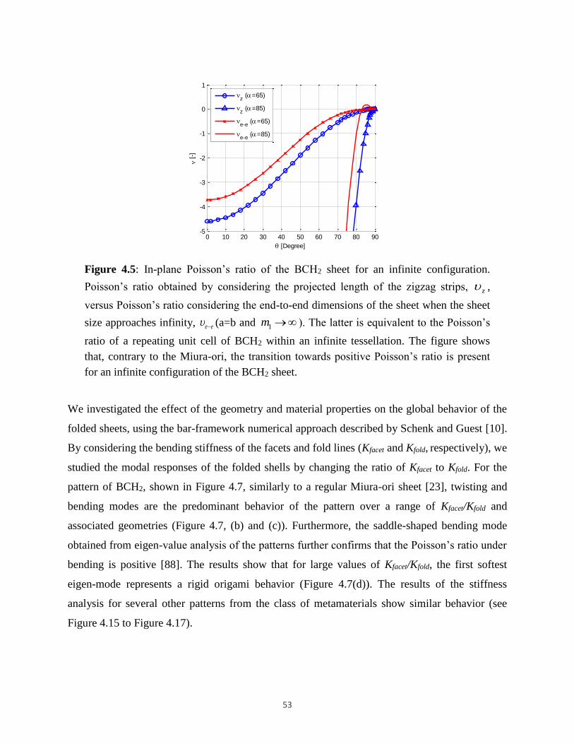
53
Figure 4.5: In-plane Poisson’s ratio of the BCH2 sheet for an infinite configuration.
Poisson’s ratio obtained by considering the projected length of the zigzag strips, z ,
versus Poisson’s ratio considering the end-to-end dimensions of the sheet when the sheet
size approaches infinity, e e (a=b and 1m ). The latter is equivalent to the Poisson’s
ratio of a repeating unit cell of BCH2 within an infinite tessellation. The figure shows
that, contrary to the Miura-ori, the transition towards positive Poisson’s ratio is present
for an infinite configuration of the BCH2 sheet.
We investigated the effect of the geometry and material properties on the global behavior of the
folded sheets, using the bar-framework numerical approach described by Schenk and Guest [10].
By considering the bending stiffness of the facets and fold lines (Kfacet and Kfold, respectively), we
studied the modal responses of the folded shells by changing the ratio of Kfacet to Kfold. For the
pattern of BCH2, shown in Figure 4.7, similarly to a regular Miura-ori sheet [23], twisting and
bending modes are the predominant behavior of the pattern over a range of Kfacet/Kfold and
associated geometries (Figure 4.7, (b) and (c)). Furthermore, the saddle-shaped bending mode
obtained from eigen-value analysis of the patterns further confirms that the Poisson’s ratio under
bending is positive [88]. The results show that for large values of Kfacet/Kfold, the first softest
eigen-mode represents a rigid origami behavior (Figure 4.7(d)). The results of the stiffness
analysis for several other patterns from the class of metamaterials show similar behavior (see
Figure 4.15 to Figure 4.17).
0 10 20 30 40 50 60 70 80 90-5
-4
-3
-2
-1
0
1
[Degree]
[
-]
z (=65)
z (=85)
e-e
(=65)
e-e
(=85)
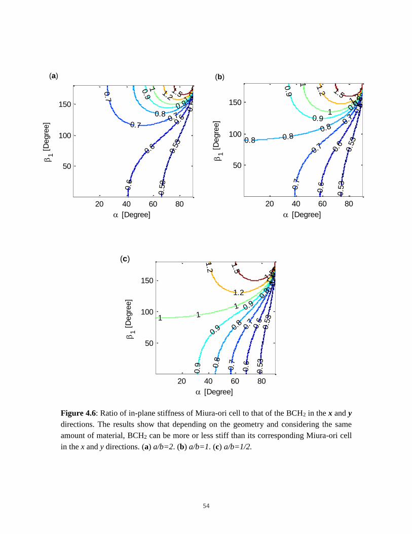
54
Figure 4.6: Ratio of in-plane stiffness of Miura-ori cell to that of the BCH2 in the x and y
directions. The results show that depending on the geometry and considering the same
amount of material, BCH2 can be more or less stiff than its corresponding Miura-ori cell
in the x and y directions. (a) a/b=2. (b) a/b=1. (c) a/b=1/2.
0.5
3
0.5
3
0.5
3
0.6
0.6
0.6
0.70.7
0.7 0
.8
0.80.9
0.9
1
1
1.21.5
[Degree]
1 [
Degre
e]
20 40 60 80
50
100
150 0.5
3
0.5
3
0.5
3
0.6
0.6
0.6
0.7
0.7
0.7
0.8
0.8
0.80.8
0.9
0.90.9 1
11
1.21.2 1.5
[Degree]
1 [
Degre
e]
20 40 60 80
50
100
150
0.5
3
0.5
30.5
3
0.6
0.6
0.6
0.7
0.7
0.7
0.8
0.8
0.8
0.9
0.9
0.9
0.9
1
111
1.2
1.2
1.2
1.5
1.5
[Degree]
1 [
Degre
e]
20 40 60 80
50
100
150
(a)
(c)
(b)

55
Figure 4.7: Behavior of sheet of the BCH2 under bending and the results of the eigen-
value analysis of a 3 by 3 pattern of BCH2. (a) A sheet of BCH2 deforms into a saddle-
shaped under bending (i.e., a typical behavior seen in materials with a positive out-of-
plane Poisson’s ratio). (b) Twisting, (c) saddle-shaped and (d) rigid origami behavior
(planar mechanism) of a 3 by 3 pattern of BCH2 (a=1; b=2; 60 ). Twisting and
saddle-shaped deformations are the softest modes observed for a wide range of material
properties and geometries. For large values of Kfacet/Kfold the rigid origami behavior
(planar mechanism) is the softest deformation mode of the sheets.
(b)
(c)
(d)
(a)

56
4.5 Discussion
Most research on origami-inspired materials relies on known patterns, especially on the Miura-
ori, i.e., a classic origami pattern with outstanding properties and a wide range of applications. In
this study, we have created the BCH2 pattern among other combined patterns and we have shown
that the patterns possess properties as remarkable as those of the Miura-ori. We summarize
significant outcomes of the current research in Figure 4.8 and discuss in the following.
Figure 4.8: Outcomes of the current study. Inspired by the Miura-ori to create the novel
BCHn zigzag-base patterns with a broad range of applications.
We have employed the concept of the in-plane Poisson’s ratio, a key material property in the
present study, in two different contexts (see Table 4.1 in supplementary material):
To describe the kinematics and to create a class of one-DOF zigzag-base mechanical
metamaterials: The Poisson’s ratio is obtained by considering the projected lengths of
the zigzag strips, z , and the value is always equal to 2tan . The value obtained in this
way is an inherent property of the class of one-DOF zigzag-base folded sheets, and is
related to the foldability of the class of the metamaterials. Hence, the concept is insightful
to create novel zigzag-base foldable materials. Note that to describe the stacking of the
Miura-ori in the literature [10], the value (i.e., 2tan ) has been associated to the

57
Poisson’s ratio of the Miura-ori sheet [10]. However, in the present work, by explicitly
associating the value to that of a one-DOF zigzag strip (Figure 4.1), we have scaled down
the width of one joining zigzag strip in the unit cell, and created the BCH patterns
containing various scales of zigzag strips. Accordingly, the present study extends the
kinematics of the Miura-ori to that of a class of one-DOF zigzag-base folded sheet
metamaterials. In other words, our work shows that all one-DOF zigzag-base folded
metamaterials shown in Figure 4.3 have identical kinematics, if the angle is the same.
To study the size change of a folded metamaterial introduced in this work: The
Poisson’s ratio is obtained by considering the end-to-end dimensions of the sheet, e e .
Note that this definition captures the size change of a finite sheet (Figure 4.4) and that of
a repeating unit cell (within an infinite configuration) for a regular sheet (e.g., regular
BCH2 - see Figure 4.5). Moreover, it is applicable for irregular sheets such as the one
shown in Figure 4.3(f).
Because recent literature on the topic had differing expressions regarding Poisson’s ratio
evaluation [10, 39, 78], by introducing a class of zigzag-base folded sheet materials, this study
further clarifies the issue and unifies the concepts. In this regard, for the Miura-ori sheet, the
Poisson’s ratio of a repeating unit cell is equal to z . Hence, the value given in [10, 39] presents
both the kinematics of the Miura-ori sheet and the size change of a repeating unit cell of the
Miura-ori. Thus, considering the end-to-end dimensions in a finite Miura-ori sheet is to simply
capture the edge effect [78] (i.e., the last term given in Equation (4.5) for the L). However, for
the BCH2 pattern, the Poisson’s ratio of a repeating unit cell is not equal to z , and it assumes
both negative and positive Poisson’s ratios due to the presence of the holes in the pattern (Figure
4.5). Therefore, our study shows that considering the end-to-end configuration for the BCH2
pattern is mainly to capture the effect of the holes in the Poisson’s ratio (i.e., the second term
within parentheses in Equation (4.5) for the L).
We have also shown that BCHn and combined patterns, introduced in this work, possess
metamaterial properties arising from their tunable geometrical configurations. An appealing
feature of these patterns is that they display similar properties to those of the Miura-ori, however,
presence of the different scales of zigzag strips in the structure of the patterns as well as

58
existence of the holes make the BCHn patterns unique (e.g., see Figure 4.4(a)). In addition, the
fact that the BCHn mechanical properties differ from those of the Miura-ori (e.g., see Figure 4.6
and Figure 4.4(d)) offer avenues to explore alternative materials and structures based on these
patterns for a certain performance/application of Miura-ori pattern on which there is a surge of
research interest. On the other hand, present technology requires lighter and more customizable
structures and materials. Combining BCHn patterns with Miura-ori provides an augmented
design space for tailored engineering design of materials and structures. Consequently,
availability of large design motifs can be advantageous, for instance, in dynamic architectural
façades where the place of the holes in the patterns can be controlled by combining Miura-ori
with BCHn to either allow light in the interior of the building or to promote shading when
desirable.
The main assumptions in this study are highlighted as: (i) to obtain the in-plane Poisson’s ratio,
we have assumed a rigid origami behavior. (ii) To perform stiffness analysis and to capture the
effect of the stiffness of the panels to that of the fold lines in the global behavior of the patterns,
we have assumed that the panels do not stretch, and bending happens only around the fold lines
(including the added fold lines).
In summary, the remarkable properties of the patterns (specifically BCH2), such as rigid-
foldability, flat-foldability, and possessing one DOF, as well as numerous possible combinations
of the patterns make them potentially suited for a broad range of applications including kinetic
and deployable structures (e.g., solar sails [24]), light cellular foldcore sandwich panels [68, 16],
3D tunable folded cellular metamaterials [10, 62, 63], energy absorbing devices [49], foldable
robots [93] and auxetic materials [88, 89]. In all these applications, scalability is a major feature
of the BCHn or other combined patterns (due to their inherent geometric properties).
4.6 Materials and Methods
To experimentally assess mechanical behavior of the origami-inspired patterns, we fabricate
samples from various types of materials including 20, 24, and 28 lb papers, 76 lb construction
paper, and 110 lb cardstock. For creating holes and patterning creases, we employ an electronic
cutter. We first design the patterns and then convert to a vector format appropriate for electronic

59
cutting. The crease lines are perforated using a dash-and-gap style. After patterning, we fold the
sheets manually along the fold lines constituting the mountains and valleys of the folded sheets.
We verify the observed behavior of the materials numerically using a stiffness analysis over a
broad range of materials including rigid panels connected via frictionless hinges.

60
4.7 Supplementary Materials
4.7.1 Geometry, pattern tessellation and combination
The geometry of BCHn (Basic unit Cell with Hole) is described in the main text and is shown in
Figure 4.2(a). The end-to-end dimensions of a sheet made of tessellation of the same BCHn (see
Figure 4.2(b)) are given by
2 2 sinW m b 1
cos 1 12 cos cos
cos
nL m a b b
n n
(4.11)
By combining BCHn with row/rows of small and/or large parallelograms with the same angle ,
we can obtain numerous unit cells. A few configurations are presented in Figure 4.9. The
tessellations or/and combinations of tessellation of these cells having the same angle can result
in a new metamaterial. For example, patterns shown in Figure 4.3 (c) and (d) are obtained by
tessellations of the unit cells presented in Figure 4.9(d).
Figure 4.9: BCH2 and BCH3 and their combinations with row/rows of small and/or large
parallelograms. (a) A BCH2 and a BCH3. (b) A BCH2 and a BCH3 combined with a row
of small parallelograms with the same geometry as the one used in the corresponding
BCH. (c) A BCH2 and a BCH3 combined with a row of large parallelograms with the
same geometry as the one used in their corresponding BCH. (d) A BCH2 and a BCH3
combined with rows of small and large parallelograms with the same geometry as the one
used in their corresponding BCH.
(a) (b) (c) (d)

61
4.7.2 Number of degrees of freedom of the patterns
For the case of n=2, i.e., for the unit cell of BCH2 pattern shown in Figure 4.2(a), and for a given
geometry of the facet, the geometry of the unit cell implies that it can be defined based on only
one fold angle (i.e., similarly to Miura-ori [10], we can write the relations between all degrees of
freedom (DOFs) based on only one fold angle, e.g., the angle ). Hence, the unit cell of BCH2
has only one DOF. On the other hand, implicit formation of the structure of the Miura-ori unit
cell with one DOF mechanism between two adjoining unit cells, as shown in Figure 4.10(a),
imposes the whole pattern to have only one DOF. The conclusion is further verified using
numerical calculation of the number of DOFs as described in Section 4.7.6.1.
Figure 4.10: Constrained DOFs by implicit formation of the structure of the Miura-ori
unit cell between adjoining unit cells of BCH2 and BCH3 in the pattern. (a) Although the
unit cell of the pattern shown, BCH2, does not have Miura-ori unit cell, the Miura-ori unit
cell structure formed implicitly in the tessellation makes the whole BCH2 pattern fold
with one-DOF planar mechanism. (b) In the symmetric tessellation of identical BCH3,
except for the small parallelogram facets of the first row, all other independent DOFs in
the unit cell of BCH3 are constrained by the structure of the Miura-ori cell formed
between two adjoining unit cells.
In general, from the numerical model described in Section 4.7.6.1 and for rigid origami behavior,
the unit cell of BCHn (Figure 4.9(a)) has 2n-3 DOFs. However, adding one row of small
Miura-ori cell
structure
Unconstrained
DOFs
Constrained
DOFs
Miura-ori cell
structure
(a) (b)

62
parallelogram facets to the BCHn (e.g., Figure 4.9(b)), i.e., creating a complete row of Miura-ori
unit cells with the small parallelogram facets, reduces the DOF of the cell to 1 irrespective of the
number of n. Hence, tessellation of the unit cells shown in Figure 4.9(b) can create patterns with
one DOF planar mechanism (e.g., Figure 4.3(e)).
For the symmetric tessellation of BCH3, as presented in Figure 4.10(b), except for the first row
of small parallelogram facets, all other independent DOFs in the unit cell of BCH3 are
constrained by the implicit formation of the structure of Miura-ori cell between two adjoining
unit cells. Hence, the pattern of BCH3, shown in Figure 4.10(b), due to existence of
unconstrained DOFs in the first row of small parallelogram facets, has more than one DOF.
However, adding one row of small parallelogram facets, and accordingly creating the row of
Miura-ori cells with small parallelogram facts can reduce the DOF of the whole system to one
(e.g., Figure 4.3(b)).
4.7.3 In-plane stretching response of BCHn sheets
4.7.3.1 Poisson’s ratio
A 5x4 sheet of BCH2 along with its corresponding Miura-ori sheet containing the same geometry
of facets and fold angle (a, b, and are identical in both models) is shown in Figure 4.4(a).
The Poisson’s ratio z for both sheets can be obtained from the following relation
/
/w z
w
d
dw w
l
l
l l (4.12)
in which l is the projected length of the zigzag strips in the xy-plane and parallel to the x-axis
(i.e., the projected lengths of the strips along any arbitrary lines of x’-x’ in the xy plane and
parallel to the x-axis intersecting a complete tessellation). Hence, for a sheet with m1 rows, l is
equal to m1 times the projected lengths of the strips in the unit cell shown in Figure 4.2(a). From
Figure 4.4(a), the importance of considering the end-to-end dimensions to obtain the Poisson’s
ratio for folded sheets is more pronounced in sheets with holes, because both sheets have the
same z despite having different lengths along the x-axis. Another example, showing the

63
relevance of the end-to-end dimensions to obtain Poisson’s ratio of folded sheets is presented in
Figure 4.11, where two identical 2x2 Miura-ori sheets are shown. Moreover, 2 rows of small
Mira-ori cells with equal z are also attached to the left-hand sample as shown in the figure.
Therefore, from the figure, considering the end-to-end dimensions to obtain Poisson’s ratio in the
left system is obvious. For the limit cases of very large number of small cells, as well as very
small length of a for small cells (i.e., n and 0sa . See Figure 4.12 for the geometry of
Miura-ori cell), the rows of small Miura-ori cells approach the lines defining the end-to-end
dimension for the 2x2 Miura-ori sheet shown on the right-hand image.
From the expression (4.6) in the main text, when2cos cos , e e is positive and for
2cos cos , e e is negative.
Figure 4.11: Concept of Poisson’s ratio considering the end-to-end dimensions. Figure
shows two identical 2x2 Miura-ori tessellations. The 2 rows of small Mira-ori cells with
the same z as that of the 2x2 sheet are attached to the left sample. Length b of the small
cells are 1/5 of that of the large cells (i.e., the number of small cells per each large cell is
5 (n=5)).
L
l
l

64
Figure 4.12: Geometry of Miura-ori cell.
For a Miura-ori (n=1) sheet, we have
2
2 1
2
1
2 cos costan
2 cos cosWL e e
m
m
(4.13)
Hence, for a Miura-ori sheet, if 1m , then e e approaches z (i.e.,
2tan ). Notice that
from the above relation, even a Miura-ori unit cell (i.e., 1 1m ) can have positive Poisson’s ratio
for some ranges.
Also, for a sheet of BCH2, we have
21
2 1
21
1
4cos cos
1tan
4cos cos
1
WL e e
m
m
m
m
(4.14)
Note that from the above relation, for a sheet of BCH2, while comparing z with e e , the shift
towards positive Poisson’s ratio in e e is mainly the effect of the holes, and thus the difference
between z and e e does not disappear (see Figure 4.5) when the length of the sheet approaches
to infinity ( 1m ). Table 4.1 summarizes the main points on the in-plane Poisson’s ratio of
the class of zigzag-base folded materials.

65
Table 4.1: Summary of main points on the in-plane Poisson’s ratio of the class of zigzag-
base folded metamaterials.
4.7.3.2 Stretching stiffness
4.7.3.2.1 BCH2
In this section, we derived the in-plane stiffness of the BCH2 in the x and y directions. The results
are also compared with those of the Miura-ori cell. For this purpose, an alternative
parameterization for BCH2 (the unit cell is shown in Figure 4.2, (a) and (b)) based on the
dihedral angles between the rigid facets is used, which is similar to the equations of reference
[39] for Miura-ori cell. To better compare the results, we kept the same symbols as those given
for Miura-ori [39], provided that they are consistent with the symbols used in this work.
Therefore,
2al 2w b 1tan cos( / 2)h a (4.15)
in which,
1sin sin / 2 and 1/2
2cos 1
(4.16)
The potential energy of a BCH2 (see Figure 4.2, (a) and (b)), subjected to uniaxial force in the x
Using projected length of the zigzag strips
Using the end-to-end dimensions of a sheet
2/tan
/z
d
dw w
l l /
/e e
dL L
dW W
v By introducing BCHn patterns, our work shows that the value is an inherent property of the class of one-DOF zigzag-base folded materials, and is always negative and is a function of the angle .
v Provides insight on the kinematics and thus on how to create zigzag-base foldable metamaterials.
v It has been used in the literature (1) as the Poisson s ratio of the Miura-ori, to describe the stacking of the Miura-ori sheets.
v By explicitly associating the value to each zigzag, and thus by changing the scale of the zigzags in the patterns, we have created the BCHn patterns.
v The value captures the size change of the sheets, and is a function of the geometry of the facets, tessellation, and the angle . It can be positive depending on the geometry.
v For an infinite tessellation of a regular sheet, it captures the Poisson s ratio of a repeating unit cell.
v The in-plane Poisson s ratio of a repeating unit cell of the Miura-ori sheet, obtained in this way, is equal to .
v For the Miura-ori, considering the end-to-end is to simply capture the edge effect (32). However, for the BCHn patterns, it is to capture the effect of the holes in the patterns.
z

66
direction, can be obtained from
H U (4.17)
in which, U and are elastic energy and potential of the applied load, respectively that are
given by
0 0
2 2
1 1 2 2
14 ( ) ( )
2U k a b (4.18)
1
10
1
1
x
df d
d
l (4.19)
where k is the rotational hinge spring constant per unit length (k). Setting the condition
1/ 0H , the external force at equilibrium xf can be obtained from
0 0
3/2 1/22 2
1 1 2 21
2
1 1
4( ) 1 ( )cos 1/ 2
/ cos sin sinx
bdU d k afd d
l (4.20)
Notice that xK is obtained from the following expression
0
1 10 0
11
1
( , ) x xx
df df dK
d d d
l l (4.21)
0
0
2 2 2 2
01 2 1/2 2 2 2 2
0 1 3
2 2
4 (1 ) cos 8 cos( , ) 2
(1 ) cos sin sin 4 cos 41 1
x
a b aK k
a a a
ll l
(4.22)
where, 00 1, . The contour plot of the stiffness ratio in the x direction (Kx/k) is shown
Figure 4.13(a) for a unit cell with a=b=1, in terms of the facet angle and fold angle 1 .
Similarly, for the y direction:

67
0 01 1 2 2 2
1
1 1
cos4 ( ) ( )
1/
/ sin cos / 2y
a bdU d k
fdw d b
(A.23)
0
1 10 0
11
1
( , )y y
y
df df dK
dw d dw
(4.24)
0
0
2 2 2
01 2 2 2 2 2
0 1
4 (1 ) cos 2( , )
(1 ) sin cos( / 2) 4 siny
a bkK
b b w
(4.25)
The contour plot of the stiffness in the y direction is shown in Figure 4.13(b) for a unit cell with
a=b=1 in terms of the facet and fold angles, and 1 , respectively.
Figure 4.13: In-plane stiffness for the BCH2 with a=b=1. (a) Kx/k. (b) Ky/k.
Note that to compare the in-plane stiffness results with those of the Miura-ori, we considered a
measure of the in-plane stiffness which is equivalent to the load making the unit displacement in
the zigzag strips of the unit cells (i.e., the length of the zigzag strips are used in the derivations).
10
10
10
20
20
20
20
50
50
50
50
50
20
0
200200
20
0
200
200 1000
10
00
10001000
10
00
10
00
1000
50000
50
000
5000050000
50000
50
000
5000
0
50000
[Degree]
1 [
Degre
e]
Kx/K
fold [1/length unit]
20 40 60 80
20
40
60
80
100
120
140
160
180
55
7
7
7
20
20
2020
10
010
0
100 100100
10
00
10
00
10
00
1000 10001000
[Degree]
1 [
Degre
e]
Ky/K
fold [1/length unit]
20 40 60 80
20
40
60
80
100
120
140
160
180
(a) (b)

68
4.7.3.2.2 Classical Miura-ori
The in-plane stretching stiffness in the x direction for Miura-ori cell is obtained by Equation
(4.21), which results in
0
0
2 2 2 2
01 2 1/2 2 2 2 2
0 1 3
2 2
(1 ) cos 8 cos( , ) 4
(1 ) cos sin sin 4 cos 41 1
x
a b aK k
a a a
ll l
(4.26)
The second term within brackets is missing in Ref. [39]. Similarly, the stretching stiffness in the
y direction is obtained by Equation (4.24), which results in
0
0
2 2 2
01 2 2 2 2 2
0 1
(1 ) cos 2( , ) 2
(1 ) sin cos( / 2) 4 siny
a bK k
b b w
(4.27)
Notice that Kx/k and Ky/k are not dimensionless, and thus Kx and Ky have dimension of the in-
plane stretching stiffness [83]. See Section 3.3.1.2 in Chapter 3 for more information.
4.7.3.2.3 In-plane Stiffness of BCH2 compared with its corresponding Miura-ori cell
Figure 4.6 shows the ratio of the in-plane stiffness of Miura-ori cell in the x and y directions to
those of the BCH2, for various ratios of a/b. The ratio is equal for both x and y directions because
only the numerators of the first term in the planar stiffness relations change from BCH2 to Miura-
ori cell, and the numerators are equal in both planar rigidities of x and y directions for a specific
unit cell.
4.7.4 Cellular folded metamaterial
Similar sheets with different heights, while possessing the same z , can be stacked and attached
together along joining fold lines to make a cellular folded metamaterials (see Figure 4.3 (g) and
(h) Figure 4.14). The fold geometry can change from layer to layer, but assuming stacking of the
patterns using 2 layers of A and B [10], and by equating the external dimensions as well as z for

69
both layers of A and B, respectively, we have
B Ab b cos
cos
AB A
B
a a
(4.28)
tanarccos cos
tan
AB A
B
(4.29)
where, the geometry of the layer B can be obtained based on that of the layer A. It is worth
noting that meeting the above equations for the stacking of the layers results in the sheets
possessing identical e e as well. This result further emphasizes the relevance of defining the
end-to-end Poisson’s ratio for the folded sheet metamaterials. Studies similar to the one given in
[10] can be done on stacked folded cellular materials developed from the patterns introduced in
this work.
The angle for the stacked samples shown in Figure 4.3(g) and Figure 4.14 is positive for both
sheets, i.e. , [0, / 2]A B . This form of stacking may be applied as impact absorbing devices
[49].
Considering the angle for one alternating layer being negative, i.e. [ / 2, 0]A results in a
new metamaterial in which the layers can be connected along joining fold lines using adhesive
(Figure 4.3(h)). In this way of stacking, the heights for two successive layers can be identical.

70
Figure 4.14: Sample stacked cellular folded metamaterials. The samples include layers of
BCH2 with two different geometries tailored for stacking. One alternating layer is almost
unfolded ( 5 ) in these samples. (a) Two BCH2 with different heights are attached
along the joining fold lines. (b) 4 layers of BCH2 with two different heights are attached
along the joining fold lines. (c) 4 layers of 2x2 BCH2 with two different heights are
attached along the joining fold lines.
4.7.5 Experimental responses of the patterns
4.7.5.1 In-plane behavior
Under in-plane extension, the patterns, for large geometric ranges (see the analytical model in the
main text), exhibit negative Poisson’s ratios. Simple in-plane experimental tests show that, for
most geometric ranges, the patterns exhibit negative Poisson’s ratio.
4.7.5.2 Out-of-plane behavior
Under bending, this class of patterns folded from various types of papers exhibit anticlastic
(saddle-shaped) curvature (see Figure 4.7(a), Figure 4.15(a), Figure 4.16(a) and Figure 4.17(a))
which is an adopted curvature by conventional materials with positive Poisson’s ratio [24].
(a)
(b)
(c)

71
4.7.6 Numerical investigation of patterns behavior
To capture the effect of geometry and material properties on the global behavior of a folded shell
system, a stiffness analysis can be carried out and the structure can be simulated using a Finite
Element Analysis (FEA). Depending on the application, either a constrained bar-framework
origami modeling approach [10, 23] or a modeling scheme using nonlinear shell elements can be
used at this stage. In the current study, to model folded shell structures, we used the pin-jointed
bar framework approach proposed by Schenk and Guest [10, 23]. In this modeling scheme, fold
lines and vertices are modeled with bars and frictionless joints, respectively. To stabilize each
facet and to model the bending of the facets for stiffness analysis, the facets are triangulated, and
additional members are added to each facet. Placing of additional members is based on
observations from physical models, stabilization of the facets, and energetic consideration in
facet bending [10]. In that way, this model considers the bending of the facets and the effect of
out-of-plane kinematics of the sheets, and therefore is not restricted to rigid origami.
By varying the ratio of the bending stiffness of the facets and fold lines (Kfacet/Kfold), we
performed stiffness analysis for 3x3 patterns of BCH2 and BCH3, and 2x3 patterns of the unit
cells shown in Figure 4.9(d) with =60 degrees, a=1 and b=2. The stiffness analysis of the
patterns reveals that twisting and bending modes are predominant behavior of the patterns over a
large range of Kfacet/Kfold and geometries (Figure 4.15-Figure 4.17, (a) and (b)). The modal shapes
corresponding to the lowest eigen-value of the sheets show that for large values of Kfacet/Kfold, the
first softest deformation mode is representing a rigid origami behavior (Figure 4.15-Figure 4.17,
(c)).
4.7.6.1 Numerical calculation of the number of DOFs of the patterns
In the bar-framework analysis, compatibility equation is to relate the nodal displacements d to
the bar extensions e via compatibility matrix C as follows
Cd e (4.30)
From the above equation, the nullspace of the compatibility matrix provides the solution in
which the bars do not extend. To model rigid origami behavior, we need to add an angular
72
constraint to the compatibility matrix whose nullspace can provide the nodal displacements d for
which the facets do not bend either. The angular constraint can be written in terms of the dihedral
fold angles between triangulated facets connected by added fold lines [10, 23]. Hence,
facet dJ d (4.31)
where is the dihedral fold angle between two adjoining triangulated facets and facetJ is the
Jacobian of the angular constraint considered for the triangulated facets intersecting by added
fold lines. Therefore, the augmented compatibility matrix is as follows
facet
CC
J (4.32)
Accordingly, the number of internal infinitesimal mechanisms (i.e., the number of independent
DOFs) can be obtained from the expression
3 ( ) 6m j rank C (4.33)
in which j is the number of joints (i.e., the number of vertices). In the above relation, the 6 DOFs
related to the rigid-body motions of 3D structures are excluded.
We used the above relation to obtain the number of DOFs for the patterns considering rigid
origami behavior. The results are justified based on the geometry of the patterns as well as
existence of the implicit formation of the structure of the Miura-ori cells with one-DOF
mechanism as described in Section 4.7.2.

73
Figure 4.15: Behavior of the sheet of BCH3 under bending and the results of eigen-value
analysis of a 3 by 3 pattern of BCH3. (a) Sheet of BCH3 deforms into a saddle-shaped
under bending which is typical behavior for materials having a positive Poisson’s ratio.
(b) Twisting, (c) saddle-shaped and (d) rigid origami behavior (planar mechanism) of a 3
by 3 pattern of BCH3 (with a=1; b=2; 60 ).
(b)
(C)
(d)
(a)

74
Figure 4.16: Behavior of a sheet of the pattern shown in Figure 4.3(c) under bending and
results of eigen-value analysis of a 2 by 3 sheet of the pattern. (a) The sheet deforms into
a saddle-shaped under bending (i.e., typical behavior seen in materials having a positive
Poisson’s ratio). (b) Twisting, (c) saddle-shaped from two different views and (d) rigid
origami behavior (planar mechanism) of a 2 by 3 pattern shown in Figure 4.3(c) (with
a=1; b=2; 60 ).
(b)
(c)
(d)
(a)

75
Figure 4.17: Behavior of a sheet of the pattern shown in Figure 4.3(d) under bending and
the results of eigen-value analysis of a 2 by 3 sheet of the pattern. (a) The sheet deforms
into a saddle-shaped under bending, i.e. a typical behavior seen in materials having a
positive Poisson’s ratio. (b) Twisting, (c) saddle-shaped from two different views and (d)
rigid origami behavior (planar mechanism) of a 2 by 3 pattern shown in Figure 4.3(d)
(with a=1; b=2; 60 ).
(b)
(c)
(d)
(a)

76
5 Tuning the Miura-ori Properties by
Dislocating the Zigzag Strips
This chapter is adapted from an article authored by Maryam Eidini, in review [94].
Abstract
The Japanese art of turning flat sheets into three dimensional intricate structures, origami,
has inspired design of mechanical metamaterials. Mechanical metamaterials are
artificially engineered materials with uncommon properties. Miura-ori is a remarkable
origami folding pattern with metamaterial properties and a wide range of applications. In
this study, by dislocating the zigzag strips of a Miura-ori pattern along the joining ridges,
we create a class of one-degree of freedom (DOF) cellular mechanical metamaterials.
The resulting configurations are based on a unit cell in which two zigzag strips surround
a hole with a parallelogram cross section. We show that dislocating zigzag strips of the
Miura-ori along the joining ridges preserves and/or tunes the outstanding properties of the
Miura-ori. The introduced materials are lighter than their corresponding Miura-ori sheets
due to the presence of holes in the patterns. Moreover, they are amenable to similar
modifications available for Miura-ori which make them appropriate for a wide range of
applications across the length scales.
Keywords: Miura-ori; Poisson’s ratio; auxetic; metamaterial; origami; kirigami; zigzag;
herringbone.
5.1 Introduction
Miura-ori, a zigzag/herringbone-base origami folding pattern, has attracted substantial attention

77
in science and engineering for its remarkable properties [71, 95, 96, 97, 98]. The exceptional
mechanical properties of the Miura-ori [97, 39], the ability to produce its morphology as a self-
organized buckling pattern [71, 95] and its geometric adaptability [99, 100] has made the pattern
suited for applications spanning from metamaterials [97] to fold-core sandwich panels [101].
Moreover, Miura-ori is a mechanical metamaterial with negative Poisson's ratio for a wide range
of its geometric parameters [65, 78]. Mechanical metamaterials are artificially engineered
materials with unusual material properties arising from their geometry and structural layout. In-
plane Poisson’s ratio is defined as the negative ratio of transverse to axial strains. Poisson’s
ratios of many common isotropic elastic materials are positive, i.e., they expand transversely
when compressed in a given direction. Conversely, when compressed, materials with negative
Poisson's ratio or auxetics contract in the directions perpendicular to the applied load. Discovery
and creating of auxetic materials has been of interest due to improving the material properties of
auxetics [89, 102, 103, 104]. Auxetic behavior may be exploited through rotating rigid and semi-
rigid units [105, 106], chiral structures [107, 108], reentrant structures [109, 110, 111], elastic
instabilities in switchable auxetics [112, 113], creating cuts in materials [114], and in folded
sheet materials [97, 65]. The latter is the concentration of the current research.
Research studies have shown that the herringbone geometry leads to auxetic properties in folded
sheet materials [97, 65] and textiles [115, 116], and its morphology arises in biological systems
[75, 76, 117]. Due to possessing unprecedented deformability, the herringbone structure
fabricated by bi-axial compression, has been also used in deformable batteries and electronics
[118, 98, 119].
Kirigami, the art of paper cutting, has been applied in science and engineering as three
dimensional (3D) core cellular structures and solar cells among others [64, 120, 121]. The
current research expands on a recent study by Eidini and Paulino [65] where origami folding has
been combined with cutting patterns to create a class of cellular metamaterials. In the present
study, we use the concept of the Poisson’s ratio of a one-DOF zigzag strip (i.e., 2
z tan )
[65] which provides inspiration to tune and/or preserve the properties of the Miura-ori. In this
regard, by dislocating the zigzag strips of the Miura-ori pattern along the joining fold lines, we
create a novel class of metamaterials. The resulting configurations are based on a one-DOF unit
cell in which two zigzag strips surround a hole with a parallelogram cross section.

78
5.2 Geometry of the Patterns
As shown in Figure 5.1, the arrangement of zigzag strips with offsets creates the parallelogram
holes in the patterns.
Figure 5.1: Crease patterns of sample zigzag-base folded materials introduced in the
current work and their unit cell. (a) Changing the direction of the offset from a zigzag
strip to the next adjoining one results in a pattern with holes oriented in different
directions - the direction of the offsets are shown with blue arrows. (b) Arranging the
offsets all to one side, results in zigzag strips with the holes all oriented with the same
direction. (c) Crease pattern of the unit cell. In the figures, the blue and red lines show
mountain and valley folds, respectively, and hatched black areas represent the places of
the cuts.
The Zigzag unit Cell with Hole (ZCH) of the patterns is shown in Figure 5.1(c) and is
parametrized Figure 5.2(a). The equations defining the geometry of the ZCH are given by
2 sinw b cos
2cos
a
l sin sinh a 0 / 2hb b b (5.1)
The expression relating the angle and the fold angle is as follows
tan cos tan (5.2)
The outer dimensions of a regular sheet of ZCH (Figure 5.2(b)) are given by
(a) (b)
(c)

79
2 2 sinW m b (5.3)
1
cos2 2b cos b b cos
cosZCH h hL m a
(5.4)
If considered in the context of rigid origami, the ZCH is a one-DOF mechanism system. Sample
patterns containing ZCH unit cells are presented in Figure 5.3, and the patterns have one DOF.
We obtain the DOF of the patterns in this work using the approach mentioned in [65].
Figure 5.2: Geometry of ZCH pattern. (a) Geometry of the unit cell. The geometry of a
ZCH sheet can be parameterized by the geometry of a parallelogram facet, hole width bh,
and fold angle [0, ] which is the angle between the edges b0 (and b) and the x-axis
in the xy-plane. Other important angles in the figure are fold angle between the facets and
the xy-plane, i.e., [0, /2]; angle between the fold lines a and the x-axis, i.e., [0,
]; Dihedral fold angles between parallelogram facets [0, ] and [0, ], joining
along fold lines a and b0, respectively. (b) A ZCH sheet with m1=2 and m2=3 and outer
dimensions L and W.
5.3 Key Mechanical Behaviors of the Patterns
Being in the class of zigzag-base patterns with one-DOF planar mechanism, the patterns of ZCH
shown in Figure 5.3 all have z equal to 2tan [65]. Using the outer dimensions of the sheet,
the Poisson’s ratio of a regular ZCH sheet (for example, sample patterns shown in Figure 5.2(b)
and Figure 5.3(a)) is given by
(a) (b)

80
2
2
2
/ cos costan
/ cos cos
LWL e e
W
dL L
dW W
(5.5)
in which
1
1 0h
m a
m b b
(5.6)
In Equation (5.4), the dimensions of a repeating unit cell of the sheet are as follows
2 sinw b (5.7)
cos2 2 cos
cosr hL a b
(5.8)
Hence, the Poisson’s ratio of a repeating unit cell (in an infinite tessellation) is given by
2
2
2
cos cos/tan
/ cos cos
r
r
L hr rL we e repeating unit cell
w h
a bdL L
dw w a b
(5.9)
The value given in the relation above presents the Poisson’s ratio of a regular ZCH sheet for an
infinite configuration as well (see Figure 4.4(a)). The value is positive if 2cos cosha b . The
value is negative if 2cos cosha b . If / ha b , the Poisson’s ratio of a repeating unit cell
approaches z . If /b a , the Poisson’s ratio of a repeating unit cell of the Miura-ori remains
as 2tan , i.e., the z (Figure 4.4(b)), but the Poisson’s ratio of a repeating unit cell of ZCH
approaches 2tan . This phenomenon happens due to the existence of the holes in the ZCH
patterns.
Upon bending, a ZCH sheet exhibits a saddle-shaped deformation (see Figure 5.6) which is a
property for materials with positive Poisson’s ratio [104]. Using the bar-framework numerical
approach [97], the results of eigen-value analysis of sample ZCH patterns reveal similar behavior
to those observed in Miura-ori and BCHn [97, 65] (see Figure 5.5 and Section 5.5 for more
details).

81
Figure 5.3: Sample patterns of ZCH. (a-e) Sample ZCH sheets created by changing the
direction and/or the amount of the offsets, in placement of one zigzag with respect to its
neighboring one, in the patterns. Note that by changing the height h, the length and width
of the parallelogram facets, the hole width (pattern (e)) and other changes (e.g., similarly
to the Miura-ori, changing the geometry of the facets to get the curved version and
others) we can produce numerous graded and/or shape morphing materials/structures.
(a) (b) (c)
(d) (e)

82
Figure 5.4: In-plane Poisson’s ratio of metamaterials introduced in this work with
infinite configurations. (a) Poisson’s ratio of Miura-ori and ZCH sheets for ( 1m ) and
a=b, and two different hole widths - the values correspond to the Poisson’s ratios of the
repeating unit cells of sheets as well. (b) Poisson’s ratio of repeating unit cells of ZCH
and Miura-ori sheets if /b a .
Figure 5.5: Results of the eigenvalue analysis of a sample ZCH sheet. (a) Twisting, (b)
saddle-shaped and (c) rigid origami behavior (planar mechanism) of a 4x4 and a 4x3
patterns of ZCH with the holes located on various directions (a=1; b=2; =60).
5.4 Concluding Remarks
In this study, we have presented a method to tune and/or keep the properties of the Miura-ori,
i.e., the most remarkable origami folding pattern. The resulting configurations are zigzag-base
(a) (b)
(a) (b)
(c)
83
patterns which are flat-foldable, developable and 1-DOF systems. The main advantages of the
patterns are highlighted as follows: (i) the patterns are amenable to similar modifications and/or
applications available for the Miura-ori (e.g., [97, 63, 100, 122, 49] - see Figure 5.7 to Figure
5.9). (ii) Due to possessing holes in their configurations, they are less dense than their
corresponding Miura-ori patterns (see Figure 5.10 to Figure 5.12). (iii) They extend geometrical
and mechanical design space of the prior known zigzag-base patterns such as Miura-ori and
BCH2 (for example, see Figure 5.4). (iv) Despite existence of the holes, they are all single‐degree
of freedom (SDOF) systems for the rigid origami behavior. SDOF rigid mechanisms are
appropriate for low energy, efficient and controllable deployable structures. (v) Compared with
BCHn patterns [65] whose unit cell includes two large and 2n small parallelogram facets, the unit
cell of the patterns introduced in this work has identical number of facets on each side of the
hole. Hence, they can be more appropriate than their corresponding BCHn patterns when
considering the thickness of the facets (e.g., when separate thick panels are connected with
frictionless hinges [123]). (vi) For applications such as sandwich folded-cores, unlike Zeta core
[68], the patterns remain developable by adding surfaces at the top and bottom of the patterns to
increase the bonding areas (see Figure 5.7) - developable sheets are well-suited for continuous
manufacturing techniques available for folded core structures. (vii) Dislocating the zigzag strips
along the joining ridges makes the ZCH patterns appropriate for design of programmable
materials and structures in which the directions and values ( hb ) of the offsets can be adjusted
depending on the external excitations.
In summary, the characteristics of the introduced patterns make them suitable for a broad range
of applications from folded-core sandwich panels and morphing structures to metamaterials at
various length scales.

84
5.5 Supplementary Materials
5.5.1 Out-of-plane behavior of the patterns
Upon bending, ZCH sheets exhibit saddle-shaped curvatures (Figure 5.6). The behavior is
typically observed in materials with positive Poisson’s ratio [104].
Figure 5.6: Behavior of sheets of the ZCH patterns under bending. ZCH Sheets deform
into saddle-shaped curvatures under bending.
5.5.2 Other variations of ZCH and their assemblages
The variation of the ZCH pattern shown in Figure 5.7 provides additional bonding areas on the
crests of the corrugation for applications as folded-core sandwich panels. Furthermore, by
changing the geometry of the facets similarly to the curved version of the Miura-ori [122], we
can create a curved version shown in Figure 5.8. In addition to the variations available for the
Miura-ori (e.g., reference [99, 122]) which are applicable to these patterns, changing the hole
width bh (Figure 5.3(f)) and the width of the bonding areas at the crests (shown in Figure 5.7)
combined with other changes can provide extensive versatility to create various variations/shapes
from the patterns.

85
Figure 5.7: A developable ZCH pattern with augmented bonding areas.
Figure 5.8: A curved ZCH pattern.
Sample one-DOF cellular materials designed based on the ZCH patterns are shown in Figure 5.9.
The stacked materials shown in Figure 5.9 (a) and (b) are appropriate for applications such as
impact absorbing devices [49]. The interleaved ZCH tubular material shown in Figure 5.9(c) is
similar to the one made from the Miura-ori pattern [63], which is a bi-directionally flat-foldable
material. Its geometry results in a material which is soft in two directions and relatively stiff in
the third direction. The samples shown in Figure 5.9(d) to Figure 5.9(f) are bi-directionally flat-
foldable materials made from different assemblages of the ZCH tubes.

86
Figure 5.9: Cellular foldable metamaterials. (a, b) Stacked cellular metamaterials made
from 7 layers of folded ZCH sheets. Each material includes two different geometries of
similar sheets. (c) Interleaved ZCH tubular materials. (d-f) Materials made from various
assemblages of ZCH tubes. (g) Sample ZCH tube with a parallelogram cross section.
5.5.3 Comparison of ZCH with Miura-ori and BCH2 for the same amount of mass
In this section, we compare the density of the ZCH with its corresponding Miura-ori and BCH2
sheets (see Figure 5.10 for sample sheets). Knowing that widths and heights of the corresponding
sheets are identical, the ratio of the density of the Miura-ori to that of the ZCH is given by
/ZCH ZCH
Miura ZCH
Miura Miura
V L
V L (5.10)
Equation (5.4) in the main text gives the length of the ZCH sheet. Note that considering 0hb in
that relation, gives the length of the Miura-ori. Hence, the ratio of the length of the ZCH to that
of the Miura-ori, i.e. /M Z , is equal to
(a) (b) (c)
(d) (e) (f) (g)

87
1
/
1
cos2 2 cos cos
cos
cos2 cos
cos
h h
ZCHMiura ZCH
Miura
m a b b bL
Lm a b
(5.11)
Therefore, the relation above is equal to the ratio of the Miura-ori density to that of its
corresponding ZCH sheet and is shown in Figure 5.11. Similarly, for BCH2 we have (see Figure
5.12)
2
2
1
/
1
cos2 2 cos cos
cos
cos 1 12 cos cos
cos 2 2
h h
ZCHBCH ZCH
BCH
m a b b bL
Lm a b b
(5.12)
Working with the relation above, the length of the hole, i.e. hb , at which the density of the ZCH
is equal to that of the BCH2 is given in the following.
1
1
1
2 2 1h
b mb
m
(5.13)
For the infinite configuration of the sheets (i.e., 1m ), the length of the hole at which the
density of ZCH is equivalent to that of the BCH2 is given by
1
4hb b (5.14)
Consequently, for 0.25hb b , the ZCH is less dense than its corresponding BCH2 sheet and for
0.25hb b , BCH2 is less dense than its corresponding ZCH sheet.

88
Figure 5.10: Sample ZCH with its corresponding Miura-ori and BCH2 sheets. (a) A 4x3
ZCH sheet with its corresponding Miura-ori with b=2a, =70 and bh= 0.3b. (b) A 4x3
ZCH sheet with its corresponding BCH2 sheet with b=2a, =70 and bh= 0.3b. (c) A 4x3
ZCH sheet with its corresponding Miura-ori with b=2a, =30 and bh= 0.3b.
(a) (b)
(c)

89
Figure 5.11: Density of ZCH compared with that of its corresponding Miura-ori. (a)
m1=4, b/a=2 and bh=0.3b. (b) m1=∞, b/a=2 and bh=0.3b. (c) m1=∞, b/a=5 and bh=0.3b.
(d) m1=∞, b/a=2 and bh=0.5b.
(a) (b)
(c) (d)

90
Figure 5.12: Density of ZCH compared with that of its corresponding BCH2 sheet. (a)
m1=4, b/a=2 and bh=0.3b. (b) m1=∞, b/a=2 and bh=0.3b. (c) m1=∞, b/a=5 and bh=0.3b.
(d) m1=∞, b/a=2 and bh=0.5b.
5.5.4 Global behavior of the patterns studied numerically
Using the bar-framework numerical approach [10], we perform eigen-value analyses of sample
patterns shown in Figure 5.3 (a) and (b), by changing the ratio of the stiffness of the facet (Kfacet)
to that of the fold line (Kfold). We observe that, similarly to Miura-ori and BCHn zigzag-base
patterns [10, 65], for small values of Kfacet/Kfold, which cover a wide range of material properties,
the twisting and saddle-shaped modes are the first and the second softest modes, respectively
(Figure 5.5 (a) and (b)). That the second softest bending mode is a saddle-shaped deformation
further shows that the material, constructed from a ZCH sheet, has a positive out-of-plane
(a) (b)
(c) (d)

91
Poisson’s ratio (see Figure 5.5(b) and Figure 5.13). Moreover, the patterns exhibit rigid origami
behavior (Figure 5.5(c)) for large values of Kfacet/Kfold which is in accordance with our
expectation.
Figure 5.13: Results of the eigenvalue analysis of a sample ZCH sheet. (a) Twisting, (b)
saddle-shaped and (c) rigid origami behavior (planar mechanism) of a 4x4 and a 4x3
patterns of ZCH with the holes located on the same directions (a=1; b=2; =60).
(a)
(c)
(b)
92
6 Lateral Force Distributions for Various Types
of Hybrid Masonry Panels
This chapter is adapted from a 2011 article by Eidini and Abrams, published in
Proceedings of 11 NAMC conference [124].
Abstract
This chapter summarizes computational analysis results carried out to study the
distribution of lateral forces between a wall and a surrounding frame in hybrid masonry
structural systems. Computational results of several multi-story, one‐bay steel frames
employing different types of hybrid masonry panels are presented. We use computational
results to demonstrate differences in lateral-force distributions in hybrid masonry systems
with different boundary conditions and with various panel aspect ratios as well as with
different stiffness of the wall to that of the frame. This study is based on structural
analyses using the hybrid masonry interfaces incorporated in the Bentley RAM Elements
software. Findings presented in this study will help enhance understanding of the hybrid
masonry behavior, and set the stage for large-scale experiments.
Keywords: Hybrid masonry, lateral force, aspect ratio, computational modeling, seismic.
6.1 Introduction
Hybrid masonry is a new technology for seismic design of structures, and was first proposed in
2007 [125]. Contrary to conventional masonry infilled frames which are usually treated as non-
structural elements in design, the innovative hybrid masonry technology is based on the
structural action of reinforced concrete masonry panels in combination with bounding steel
frames as well as novel steel connectors where the panels including masonry wall, steel frame
93
and steel connectors are designed to resist lateral seismic forces. Depending on the boundary
conditions between a masonry panel and a surrounding frame, hybrid masonry panels are
categorized into three major groups namely hybrid Types I, II, and III. There are two more sub
classifications for hybrid Types II and III. If a panel is resisting overturning moments by tensile
force in vertical reinforcement, it is considered as Type IIa or IIIa. If it is resisting the
overturning moments by bearing contact at the top and bottom of the panel and strut action, it is
categorized as Type IIb or IIIb [126].
In this chapter, the effect of aspect ratio and wall stiffness on distribution of lateral load between
a panel and a frame in various types of hybrid masonry panels is studied. Furthermore, the effect
of story level on lateral load distribution is taken into account. Additionally, the effect of lateral
load pattern using two different load patterns of inverse triangular and rectangular on the results
is compared for the prototype frame described in the following section. This study was part of
the NSF NEESR-CR: Hybrid Masonry Seismic Structural Systems research project [127].
6.2 Example Structure Considered in the Analyses
A four-story one-bay steel frame shown in Figure 6.1 under inverse triangular lateral load is
considered for exploratory studies. The columns are W12x65, and the beams cross sections are
W16x40. The thickness of the wall is 12 inches (30.48 cm). The frame employing five different
types of hybrid panels including Type I, IIa, IIb, IIIa, and IIIb has been considered for one set of
analyses. They are modelled using hybrid masonry interfaces of RAM Elements software [128]
to study the effect of aspect ratio, and various boundary conditions on lateral load distribution.
To evaluate the effect of wall thickness, one more set of analyses using the aforementioned
hybrid panels, but with a thickness of wall equal to 6 inches (15.28 cm) has been carried out. All
column heights (h) are 10 ft (3.048 m), and to generate the different aspect ratios only the frame
bay width (L) has been changed in the models.

94
Figure 6.1: Four-story one-bay steel frame used in the analyses.
6.3 Lateral Load Transfer Mechanism in Hybrid Masonry Panels
The various interfacial conditions in hybrid masonry panels explicitly constitute the type of
interaction between the frame and the masonry panel. This interaction is the main part in
understanding the load transfer mechanism as well as in assessing the behavior of the panels.
Pook and Dawe among others tested several large-scale infill panel specimens, and studied the
influence of boundary conditions between a wall and a frame on behavior of infill systems. It
was concluded that interface conditions significantly affected the initial stiffness and strength of
the infill, and that the best overall performance was the case in which a panel is constructed in
close contact with the moment-resistant frame without having either ties between the wall and
the frame or separating them, for example using interfacial membrane [129, 130].
What presented in the following are the theoretical backgrounds and results aim at improving our
understanding of the behavior of various types of hybrid masonry panels, with unknown
structural behavior to us at the beginning of the present research. Furthermore, the results would
be tempered through the course of the project and after having the results of the tests on several
large-scale specimens as well as on steel connector plates [127].

95
6.3.1 Hybrid Type I
In hybrid Type-I, among all the actions, only shear force transfers to the wall, and there is no
axial load transmission due to existence of gaps between the masonry wall and the frame as well
as presence of slotted holes in the steel connectors. The transfer of story shear is through the steel
links connecting the beam to the masonry wall. To have a continuous lateral load path there
should be shear connectors at the interface of the wall and the beam below. In this kind of hybrid
panel, steel connectors are acting in series with the masonry panel and the system of these two is
performing in parallel with the bounding frame (see Figure 6.2). According to Figure 6.2, and
considering that each connector plate is behaving like a cantilever beam, we have:
Lateral stiffness of each steel connector = 33 /connectors connectorsEI h
Lateral stiffness of wall ≈ 33 /wall wallEI h (considering the wall base is fixed)
Therefore, the ratio of the lateral stiffness of the connectors to that of the wall is proportional to
3( / )wall connectorh h which provides a large lateral stiffness ratio of the connectors to that of the wall
even for small ratios of )/( wallconnectors II .
Since the wall is connected to the steel connector plates in series (Figure 6.2(b)), and considering
the large lateral stiffness ratio of the connectors to that of the wall, the stiffness of the system of
the wall and connectors will be governed by the smaller lateral stiffness, i.e. lateral stiffness of
the wall. Thus,
WCCW KKK
111 (6.1)
For rigid connectors: WCW KK (6.2)
in which, CWK is the lateral stiffness of the connectors and the wall acting in series; WK is the
lateral stiffness of the wall; CK is the lateral stiffness of the connectors. Since WK is much larger
thanframeK , almost all lateral shear is attracted by the wall at each story level.
Based on the above-mentioned mechanism, the value of the shear at the story level i, iV , and the

96
value of the axial load in each column at story level i, iP , can be calculated by the following
formula:
n
i j
j i
V F
(6.3)
L
hFPP i
n
ij
jii1
1
1
(6.4)
where i is the story level index; n is the total number of stories; iP is axial force due to lateral load
in each column at level i; jF is the lateral force at level j;
1ih is the story height for the story
level i+1; L is the bay width.
By substituting corresponding values for 2iP , 3iP , …, nP in the above formula, one can get:
n
ik
kki
L
hVP
1
(6.5)
where, kV is the story shear in story level k, and kh is the story height for the same story level.
Hence, the overturning moment of the frame at level i is equal to:
n
ik
kkiFrame hVM1
(6.6)

97
(a) (b)
Figure 6.2: (a) Hybrid masonry panel Type I; (b) Schematic connection of elements in a
hybrid masonry panel Type I.
A sample vertical stress distribution for hybrid Type I is shown in Figure 6.3(a). Flexural action
of a masonry panel along a story height is evident by the pattern of vertical normal stresses. Type
I hybrid panels, due to presence of slotted holes in the steel connector plates, do not transfer
vertical forces from the top story to the bottom one. Hence, the vertical stresses are not
continuous from one panel to another, as shown in Figure 6.3(a).
6.3.2 Hybrid Types II and III
In hybrid Type II, the wall is in contact with the beams, but there are gaps at the sides which
prevent interaction of the wall with the surrounding frame. Also, in hybrid Type III similar to
traditional infill panels, there is no gap between the wall and the frame, and the walls are
constructed tight at the columns and the top of the wall. Moreover, Types a and b are sub
categories for hybrid Types II and III. In hybrid Types IIa, and IIIa similar to hybrid Type I the
reinforcing bars of the wall are welded to the beam below. Therefore, the contribution of the wall
to the story overturning moment is through flexure of the reinforced section. However, in hybrid
Steel Connectors
Wall
Surrounding Frame
Steel Connectors
Masonry Wall
Steel Column
Steel Beam
Steel beam or Foundation
Level

98
Types IIb, and IIIb the contribution of the wall to the story overturning moment is a result of
bearing and strut action of the panel. Sample contours of vertical stresses developed in the wall
for the example structure employing hybrid panels Types IIa, and IIIa under a triangular lateral
load pattern are shown in Figure 6.3 (b) and (c), respectively.
(a) Type I (b) Type IIa (c) Type IIIa
Figure 6.3: Sample vertical stress distribution for hybrid Types I, IIa and IIIa for the
example frame with aspect ratio 1.5 under triangular lateral load pattern.

99
(a) (b)
Figure 6.4: (a) Sample vertical stress distribution in shear wall system for the example
frame with aspect ratio 1.5 under triangular lateral load pattern. (b) Ratio of overturning
moment in the wall to that of the frame in the 1st and 4th stories for shear wall system
and hybrid Type IIIa.
Figure 6.3(c) shows an essentially continuous vertical stress distribution in hybrid Type IIIa.
Comparison of the vertical stress distribution in hybrid Type IIIa (Figure 6.3(c)), and shear wall
(Figure 6.4) reveals the similarity of the behavior of these two lateral load resisting systems.
Figure 6.4(b) illustrates the ratio of overturning moment in the wall to that of the frame in the 1st
and 4th stories for both shear wall system and hybrid masonry Type IIIa. The results of both
systems are well-matched, as shown in Figure 6.4(b).
0.00
0.50
1.00
1.50
2.00
2.50
0 1 2 3M
w/M
F
L/h
4th (SW)
1st (SW)
4th (IIIa)
1st (IIIa)

100
6.4 Effect of Aspect Ratio and Wall Stiffness on Distribution of Lateral Force
between Wall and Frame
To study the lateral load distribution in various types of hybrid masonry panels, several four-
story one-bay frames employing hybrid masonry panels described in previous sections have been
modeled using RAM Elements software [128]. The graphs presented in Figure 6.5 and Figure 6.6
are obtained from 54 such models. They show the effect of aspect ratio (frame bay to the story
height), and wall thickness on contribution of the wall overturning moment to the story
overturning moment as well as on the ratio of the wall overturning moment to that of the frame,
respectively. In these studies, the structures are subjected to an inverse triangular lateral load
pattern with the lateral load equal to 8.82 Kips (39.23 KN) at the top. Decreasing the wall
thickness while keeping all other parameters unchanged has resulted in reduction of the wall
contribution to the overturning moment which is in accordance with the expectations (see Figure
6.5 and Figure 6.6). Moreover, for the panels having the walls with thickness of 6 inches, similar
behavior to those of the walls with thickness of 12 inches is observed (Figure 6.5 and Figure
6.6). For example, for hybrid panels Type II-a, III-a, and III-b for both thicknesses of 6 and 12
inches overturning moment in the wall increases by increasing the aspect ratio. Because, by
increasing the aspect ratio, the axial load in columns decreases which will result in reduction of
overturning moment in the frame and accordingly increasing the overturning moment in the wall.
For hybrid Type I, overturning moment in the frame at each story level is constant, and depends
on both the story shear and geometry of the frame, as Equation (6.6) shows. Therefore, based on
the formula overturning moment in the wall is constant as well. The results presented in Figure 5
obtained from RAM Elements also show that the overturning moment in the wall is constant for
a wide range of aspect ratios. As discussed under “Hybrid Type I”, the effect of frameK has been
disregarded. However, for small aspect ratios the assumption is not necessarily true. Therefore,
some parts of the story shear will be resisted by the frame, resulting in a smaller shear in the
wall, and consequently smaller overturning moment in the frame than that discussed earlier.
Hence, in hybrid Type I, for small aspect ratios, the wall overturning moment is slightly greater
than the value for large aspect ratios, as Figure 6.5 presents.
In hybrid Type IIIa, contrary to hybrid Type IIa, the masonry wall is in contact with the columns
as well. Therefore, part of axial loads in the wall will transfer to the columns through the contact
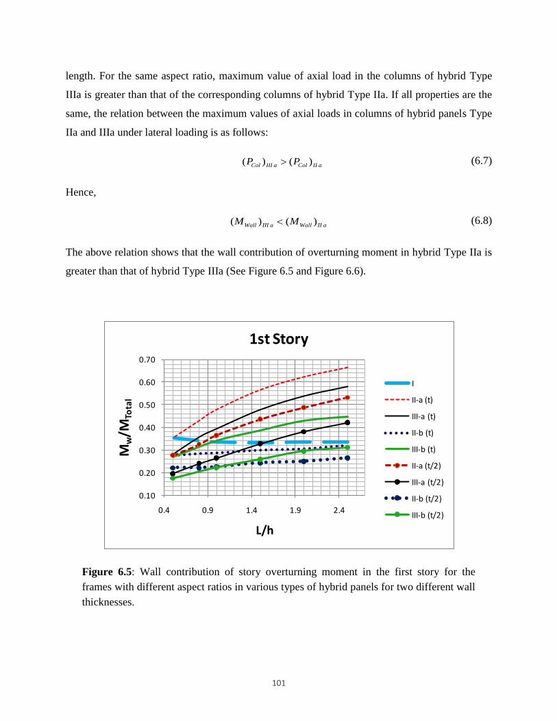
101
length. For the same aspect ratio, maximum value of axial load in the columns of hybrid Type
IIIa is greater than that of the corresponding columns of hybrid Type IIa. If all properties are the
same, the relation between the maximum values of axial loads in columns of hybrid panels Type
IIa and IIIa under lateral loading is as follows:
( ) ( )Col III a Col II aP P
(6.7)
Hence,
( ) ( )Wall III a Wall II aM M
(6.8)
The above relation shows that the wall contribution of overturning moment in hybrid Type IIa is
greater than that of hybrid Type IIIa (See Figure 6.5 and Figure 6.6).
Figure 6.5: Wall contribution of story overturning moment in the first story for the
frames with different aspect ratios in various types of hybrid panels for two different wall
thicknesses.
0.10
0.20
0.30
0.40
0.50
0.60
0.70
0.4 0.9 1.4 1.9 2.4
Mw
/MTo
tal
L/h
1st Story
I
II-a (t)
III-a (t)
II-b (t)
III-b (t)
II-a (t/2)
III-a (t/2)
II-b (t/2)
III-b (t/2)

102
Figure 6.6: Ratio of wall contribution of story overturning moment to that of the frame
contribution in the first story for the frames with different aspect ratio in various types of
hybrid panels for two different wall thicknesses.
6.5 Effect of Story Level on Distribution of Lateral Force between Wall and
Frame
In this section, the distribution of lateral load between the wall and the frame of hybrid masonry
Types I, IIa, and IIIa at different stories are studied. The results are summarized in Figure 6.7-
Figure 6.9. As illustrated in the figures, the ratio of the wall contribution of the overturning
moment to that of the frame is increasing in upper stories. This trend is similar to that found in a
shear wall. Specifically, the results obtained in hybrid Type IIIa (Figure 6.9) are in very close
agreement with the results obtained from the shear wall system (Figure 6.4(b)). This similarity is
due to the continuity of the lateral load path between the wall above and the one below a beam in
hybrid Type IIIa systems.
0.00
0.50
1.00
1.50
2.00
2.50
0.4 0.9 1.4 1.9 2.4
Mw
/MF
L/h
1st Story
I
II-a (t)
III-a (t)
II-b (t)
III-b (t)
II-a (t/2)
III-a (t/2)
II-b (t/2)
III-b (t/2)

103
Figure 6.7: Wall contribution to story overturning moment in different stories for the
frames with different aspect ratio in hybrid Type I.
Figure 6.8: Wall contribution to story overturning moment in different stories for the
frames with different aspect ratio in hybrid Type IIa.
0.00
0.50
1.00
1.50
2.00
0 0.5 1 1.5 2 2.5 3
Mw
/MF
L/h
Type I
3rd Story
2nd Story
1st Story
0.00
0.50
1.00
1.50
2.00
2.50
3.00
3.50
4.00
0 0.5 1 1.5 2 2.5 3
Mw
/MF
L/h
Type IIa
4th Story
3rd Story
2nd Story
1st Story

104
Figure 6.9: Wall contribution to story overturning moment in different stories for the
frames with different aspect ratio in hybrid Type IIIa.
For hybrid Types IIa and IIIa, the ratio of the wall overturning moment to that of the frame at all
stories increases, as the aspect ratio increases (see Figure 6.8 and Figure 6.9). This fact is due to
the reduction of axial load in columns as discussed earlier.
6.6 Effect of the Lateral Load Patterns on Distribution of the Lateral Forces
between Wall and Frame
To evaluate the effect of lateral load distribution pattern on distribution of lateral forces between
a frame and a wall in hybrid masonry systems, the response of the example frame employing
different types of hybrid panels with various aspect ratios subjected to a rectangular lateral load
pattern is compared in Figure 6.10 with the behavior of the corresponding hybrid systems
subjected to an inverse triangular lateral load. To have a rational comparison on the effect of
lateral load patterns, the rectangular load pattern has been chosen so that the sum of lateral loads
is equal to that of the triangular load pattern. Additionally, the comparison has been made for the
first story for which the story shear is the same in both lateral load patterns. The value of the
lateral load in rectangular load pattern at all levels is equal to 5.51 Kips (24.52 KN).
0.00
0.50
1.00
1.50
2.00
2.50
0 0.5 1 1.5 2 2.5 3
Mw
/MF
L/h
Type IIIa
4th Story
3rd Story
2nd Story
1st Story
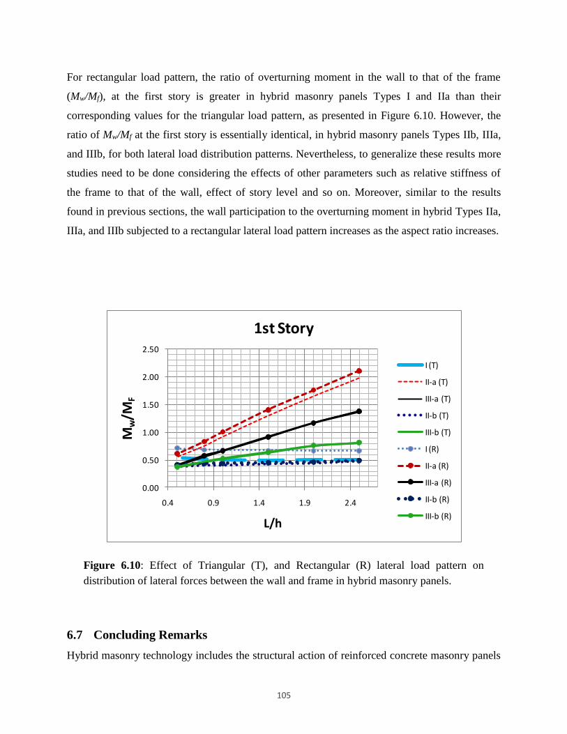
105
For rectangular load pattern, the ratio of overturning moment in the wall to that of the frame
(Mw/Mf), at the first story is greater in hybrid masonry panels Types I and IIa than their
corresponding values for the triangular load pattern, as presented in Figure 6.10. However, the
ratio of Mw/Mf at the first story is essentially identical, in hybrid masonry panels Types IIb, IIIa,
and IIIb, for both lateral load distribution patterns. Nevertheless, to generalize these results more
studies need to be done considering the effects of other parameters such as relative stiffness of
the frame to that of the wall, effect of story level and so on. Moreover, similar to the results
found in previous sections, the wall participation to the overturning moment in hybrid Types IIa,
IIIa, and IIIb subjected to a rectangular lateral load pattern increases as the aspect ratio increases.
Figure 6.10: Effect of Triangular (T), and Rectangular (R) lateral load pattern on
distribution of lateral forces between the wall and frame in hybrid masonry panels.
6.7 Concluding Remarks
Hybrid masonry technology includes the structural action of reinforced concrete masonry panels
0.00
0.50
1.00
1.50
2.00
2.50
0.4 0.9 1.4 1.9 2.4
Mw
/MF
L/h
1st Story
I (T)
II-a (T)
III-a (T)
II-b (T)
III-b (T)
I (R)
II-a (R)
III-a (R)
II-b (R)
III-b (R)

106
in combination with surrounding steel frames as well as novel steel connectors. One of the
advantages of the system includes: the bracing of a steel frame by the use of reinforced masonry
panels will lead to an integrated, efficient application of both materials. This research
summarizes the results of exploratory studies performed to improve understanding of the
behavior of various types of hybrid masonry panels. Particularly, the chapter’s focus is to
understand the effect of aspect ratio and relative stiffness of the wall to that of the frame as well
as the effect of lateral load pattern on lateral load distribution in various types of hybrid masonry
panels. The main results obtained through this study are listed as follows:
For hybrid Type I, overturning moment in both the wall and the frame is constant for
various aspect ratios, and the ratio of the wall to the frame contribution is dependent on
the system geometry and applied lateral load pattern.
Comparison of the vertical stress distribution in hybrid Type IIIa, and shear wall reveals
very close similarity of the behavior of these two lateral load resisting systems. In
addition, the study of contribution of the overturning moment in the wall and the frame in
both shear wall and hybrid masonry Type IIIa systems shows that the behavior of these
two lateral load resisting systems are very close to each other.
In hybrid Types IIa, IIIa, and IIIb at all story levels, wall contribution of overturning
moment increases with increasing aspect ratio, and having all other parameters
unchanged. Frame contribution to overturning moment decreases with increasing aspect
ratio. Axial load in columns decreases with increasing aspect ratio in all three
aforementioned hybrid panels.
In hybrid panels Type I, IIa, and IIIa wall contribution to story overturning moment
increases at higher story levels. This behavior is similar to the behavior of the shear
walls.
The wall contribution to overturning moment in hybrid panel Type IIa is greater than that
in hybrid panel Type IIIa, if all the properties and lateral loading in both panels are the
same. This is mainly due to the fact that the axial load is smaller in columns of hybrid
Type IIa which will accordingly lead to a greater overturning moment in the wall of
hybrid panel Type IIa.
To understand the behavior of the panels in hybrid Types IIb and IIIb, and rationalize the

107
findings in this chapter for these types of hybrid panels more research needs to be
performed.

108
7 Seismic Design and Viability of Hybrid
Masonry Building Systems
This chapter is adapted from a 2013 article by Eidini et al., published in ASCE Journal of
Structural Engineering [131].
Abstract
Hybrid masonry is an innovative technology for seismic design of buildings. The system
utilizes reinforced masonry panels within a steel-framed structure, where steel connector
plates link the steel frame to the masonry panels. The system has been used for
construction of low-rise buildings in the low-seismic regions of the eastern and mid-
western United States, but has not been implemented in regions of moderate or high
seismicity yet. Current research is underway to extend the application of hybrid masonry
for use in high-seismic regions. In this chapter, the overall approach for seismic design
of one type of hybrid masonry systems is studied and the steps of a capacity design
process are presented, where two favorable ductile modes of behavior may be exploited:
steel connector plates behaving as fuses or flexural yielding of the masonry panels.
Moreover, this research applies the two design options for three, six, and nine-story
prototype buildings located in a high seismic region, and evaluates viability of hybrid
masonry as a new seismic lateral-load resisting system. Based on this design framework
and the exploratory studies, both approaches are shown to be feasible for developing
realistic system configurations. Nevertheless, for the case of flexural yielding of the
masonry panels, the steel connector plates must carry significant shear force demands.
The structural system then requires more hybrid panels compared with corresponding
systems when plasticity is concentrated in the steel connector plates.
Keywords: Seismic Design; Hybrid Masonry; Capacity Design; Connections; Structural Fuses;
Ductility.

109
7.1 Introduction
Hybrid masonry, which was first proposed in 2007 [125], is an innovative lateral-load resisting
system that synergistically combines masonry panels and a steel frame. As mentioned by Bertero
and Broken [132], the key principle for seismic resistant design is to use the necessary mass in
the system to resist seismic forces. Hybrid masonry takes advantage of masonry walls present in
most buildings as non-structural elements (i.e., the necessary mass) and uses special details to
make them part of the lateral-load resisting system. Unlike common masonry infill panels, the
innovative aspect of hybrid masonry panels is the intentional detailing of the connections
between the masonry panels and the steel frame such that predictable, robust and ductile
behavior is ensured. Additionally, reinforced masonry panels are used in the system, rather than
unreinforced as are commonly used in masonry infill walls.
The presence of masonry panels in hybrid masonry systems changes the lateral-load transfer
mechanism of the structure from predominantly frame or truss action, depending on whether the
steel frame is unbraced or braced, to a combined truss-shear wall action. Since most low-rise
steel buildings are braced frames, the masonry panels can be viewed as surrogate bracing
elements. Based on the boundary conditions between masonry panels and the surrounding steel
frame, hybrid masonry systems are categorized into three major groups: Types I, II, and III
(NCMA TEK 14-9A 2009) [126]. This research focuses on hybrid masonry Type I, which will
be discussed in more detail below.
Hybrid masonry construction has been introduced to the eastern United States for low-rise office
and commercial buildings, and it has been found to reduce cost and expedite construction since
structural and architectural components can be integrated. However, it has not been used in
regions of high seismicity yet. The research described in this chapter is part of a comprehensive
effort to characterize the inelastic behavior of hybrid masonry and develop design methods so
that it can be implemented in high seismic regions.
Since the system is new, research on hybrid masonry is in its infancy. Sample construction
details of hybrid masonry panels are provided by the National Concrete Masonry Association
(NCMA TEK 3-3B 2009) [133]. An overview of current research on hybrid masonry panels is
given in [127]. Eidini and Abrams [124] performed an exploratory study on distribution of lateral

110
forces between a masonry panel and a frame using models of four-story, one‐bay steel frames
employing different types of hybrid masonry panels. The effects of various parameters such as
panel aspect ratio and lateral-load distribution pattern were taken into account. Johnson et al.
[134] performed an experimental study to establish the strength and hysteretic behavior of
connector plates, and to develop ductile energy dissipating fuse connector plates for use in
hybrid masonry Type I systems. They tested the connector plates under cyclic lateral loading,
and developed steel connectors and ductile fuses with various geometric configurations. Further
research on development and design of steel connector plates for use in hybrid masonry
structural systems can be found in Goodnight et al. [135] and Ozaki-Train and Robertson [136].
The purpose of this research is to establish a framework for the application of hybrid masonry to
construction in areas of moderate and high seismicity. The main contribution of this study is to
present simplified formulas for lateral-load analysis of hybrid masonry Type I, as well as to
provide systematic approaches for seismic design of hybrid masonry as efficient lateral-load
resisting systems. The design methodologies presented in the chapter are based on the widely
accepted capacity design approach [137].
In addition, application of the proposed approaches is used in an exploratory parametric study,
which is done to evaluate the viability of hybrid masonry Type I. The current study precedes a
large-scale experimental program and computational studies as discussed in [127]. There are no
provisions in current codes that define seismic response factors [138], such as the response
modification coefficient (R) and the system over-strength factor (Ω0) for hybrid masonry
systems. Hence, in the portion of this study on evaluating feasibility of these systems, the
demands on the structural elements are calculated assuming a range of likely values for these
currently-undefined seismic design parameters. The values for these parameters are assumed
based on the current code provisions [138] for systems with similar behavior.
This chapter focuses on hybrid masonry Type I and is organized as follows. Hybrid masonry
Type I and its lateral-load transfer paths are discussed in the next section. Seismic design
procedures are then presented for buildings incorporating hybrid masonry Type I. Using the
proposed design methodologies, viability of hybrid masonry building systems is investigated for
use in high seismic regions. The last section provides some concluding remarks and areas for

111
further research.
7.2 Hybrid Masonry Type I
7.2.1 Force transfer mechanisms
In general for hybrid masonry systems, a reinforced concrete masonry panel is attached to a
structural steel frame such that gravity forces, story shears and overturning moments can be
transferred to the masonry. Type I is the simplest form of hybrid masonry since only horizontal
shear force transfers from the steel frame to the top of each panel. As shown in Figure 7.1(a),
there is no axial load transmission due to gaps between the top of the masonry panel and the
frame and vertically slotted holes in the steel connectors. A steel connector comprises two steel
connector plates, one on each side of the masonry panel, and a through bolt. Hence, a masonry
panel at a level functions as an isolated shear wall and vertical stresses in the masonry are not
continuous over the height. The transfer of story shear is through the steel connectors attaching
the beam to the masonry panel. The structural masonry panel acts as a lateral bracing member
and can be reinforced both vertically and horizontally to resist lateral forces and to develop the
deformation capacity of a well-detailed reinforced masonry shear wall. To prevent sliding of the
masonry panel and to provide a continuous lateral-load path there must be adequate connections
at the interface of the masonry panel and the supporting beam below.
In hybrid masonry Type I, steel connectors are acting in series with the masonry panel and the
system of these two elements is acting in parallel with the surrounding frame (see Figure 7.1).
Steel connectors are shown schematically in this figure, but realistic details are achieved by
attaching to both flanges of the beam above with a combination of welds and bolts. The
robustness of this configuration permits the connection between a connector and the beam to be
idealized as fixed. Therefore, each connector plate is behaving like a cantilever beam, and the
lateral stiffness of a steel connector with constant cross section is KCP=3 ESICP/LCP3, where, Es is
the modulus of elasticity of steel; ICP is the moment of inertia of a steel connector; LCP is the
length of a connector. In addition, the lateral stiffness of a cantilever panel is [139]
Kpa≈bEm/[4(hpanel/Lpanel)3+3(hpanel/Lpanel)] where Em is the modulus of elasticity of masonry; hpanel
is the height of the panel; b is the net thickness of the panel; Lpanel is the length of the panel.

112
Therefore, since the panel is connected to the steel connectors in series (Figure 7.1(b)), the
stiffness of the system of the panel and connectors will be:
CPa C Pa C PaK K K / ( K K ) (7.1)
where KC is the lateral stiffness of the steel connectors (equal to the lateral stiffness of each steel
connector, KCP, multiplied by the number of connectors per panel, NCP_panel) and KPa is the lateral
stiffness of the panel. Since the total stiffness in such a series system is dominated by the more
flexible element, the connector plates in hybrid masonry Type I, which are much more flexible
than the masonry panels, play an important role.
Figure 7.1: (a) Hybrid masonry Type I; (b) Schematic connection of elements in hybrid
masonry Type I building systems.

113
In hybrid masonry systems, the steel beams are connected using details that transfer limited
moment, so the steel frame is not considered to contribute lateral stiffness. KCPa is then much
greater than lateral stiffness of the surrounding frame, KFrame. Hence, almost all the lateral shear
is attracted by the masonry panel and steel connector system at each story level. For taller
structures, steel column axial flexibility reduces the overall system stiffness and should be
considered in design.
Based on the assumptions that the steel beams have pinned ends and only horizontal shear is
transferred into the top of the masonry panel at floor level, the value of the shear in story i, Vi,
and the value of axial force due to lateral-load in each column in story i, Pi, can be calculated by
the following expressions:
n
i j
j i
V F
(7.2)
11
1
nCPi i
i i j i
j i
hhP P F F
L L
(7.3)
where i is the story index; n is the total number of stories; Fj is the applied lateral force at level j;
hi+1 is the story height for story i+1; L is the bay width; hcp is the vertical distance from the
through bolts to the point of application of the story force (see Figure 7.2).
Assuming hcp is the same in all stories, and by substituting corresponding values for Pi+1, Pi+2,
…, Pn in Equation (7.3), one can get:
1
n
j j i CP
j i
i
V h V h
PL
(7.4)
where Vj is the story shear in story j and hj is the story height for the same story. For short
connectors, the last terms in the above equation is small and can be ignored. However, in
realistic situations the length of the connectors cannot be neglected.

114
Figure 7.2: Parameters used in lateral load analysis of hybrid masonry Type I.
7.2.2 Ductile limit states
Under in-plane lateral-loads, a hybrid masonry panel can reach a desirable ductile limit state and
sustain inelastic demands through two mechanisms: yielding of the steel connector plates or
yielding of the vertical steel reinforcement in the masonry panels. Non-ductile limit states, such
as break-out/bearing failure where the steel connector plates are bolted to the masonry panel
(discussed below), column buckling, beam hinging and connection failure, are undesirable and
must be prevented through capacity-design procedures. The behavior of a reinforced masonry
panel in the hybrid masonry system is similar to that of a conventional reinforced masonry shear
wall. In a reinforced masonry shear wall under lateral load, the controlling limit state is either
flexure or shear. In a well-designed flexural-controlled wall, horizontal cracks appear at the wall
heel, the vertical reinforcing bars yield before toe crushing of the masonry such that inelastic
deformation can be sustained prior to strength degradation. In this case, toe crushing or rupture
of the extreme tensile bars causes the final failure. Increasing the amount of vertical
reinforcement or the length-to-height ratio of the wall increases the likelihood of shear failure

115
[140]. The flexural failure mode of steel connector plates is shown in Figure 7.3(a), and the
flexural failure mode of a masonry panel is presented in Figure 7.3 (b).
(a) (b)
Figure 7.3: Flexural failure modes in hybrid masonry Type I. (a) Flexural yielding of
connector plates. Yielding of connector plates are shown in circles. (b) Flexural yielding
of masonry panels. Flexural cracks at the heel and toe crushing are shown on the bottom
left and right sides of the panel, respectively. To make the deformed shapes more
illustrative, the gaps are shown wider than their normal sizes in a scaled picture.
Whereas the limit states discussed above are desirable for seismic response due to their ductile
character, an undesirable non-ductile failure mode for hybrid masonry Type I is break-
out/bearing failure of the masonry panel at the points where steel connector plates are attached.
Break-out/bearing is a brittle failure mode, and is due to the stress concentrations at the
connections of the bolts with the masonry panels. To prevent this failure mode, the portion of the
story shear force transferred from a pair of connector plates to a masonry panel is required to be
smaller than the shear break-out/bearing strength of a masonry panel. Shear break-out/bearing
strength is defined in the next section.
7.2.3 Non-ductile break-out/bearing strength
The Building Code Requirements for Masonry Structures [141] provides guidelines for anchor

116
bolts embedded in masonry, but thru-bolts are not addressed. To determine the nominal shear
strength of anchor bolts, the MSJC [141] addresses the possible failure mechanisms as follows:
masonry break-out, masonry crushing, anchor bolt pry-out, and steel yielding. Although the
MSJC provisions do not address the thru-bolt connection that is used in hybrid masonry panels,
Goodnight et al. [135] used them to provide an estimate for the nominal shear strength to assess
the performance of the connections. Furthermore, to establish the break-out strength of the
connections, they performed push out tests on embedded thru-bolts in masonry wall specimens.
They tested four specimens loaded in displacement control. Most specimens were also loaded in
two directions until failure occurred. The specimens showed a masonry break-out strength at
least equal to 89kN (20kips) [136].
7.3 Seismic Design Methodologies for Hybrid Masonry Building Systems
Code-based seismic design is most commonly conducted using the equivalent lateral force
procedure [138], and the objective is to prevent structural collapse by dictating favorable limit
states in the structure. A favorable limit state corresponds to the ductile behavior of the structure
as a whole. Seismic design provisions are based on the capacity design approach through which
certain structural components are designated as the “dissipative components” or “fuses” and are
specially detailed for high energy absorption during a major seismic event. Inelastic response in
the “dissipative components” should not impair the gravity load-carrying capacity and the global
stability of the system. All other structural components including connections are proportioned in
accordance with the capacity design concept [137], and this is typically done by considering
adequate over-strength factors to ensure nearly elastic behavior [142, 143].
For hybrid masonry panels, two design approaches are considered for detailing of components.
The major considerations of each approach are listed in Table 7.1. The goal is to guarantee a
favorable response of the hybrid masonry structural system through utilizing a combination of
“dissipative components” with high inelastic deformation capacity, as well as elastic elements
with high load capacity. The approaches are described in the following.

117
Table 7.1: Main considerations in capacity design of hybrid masonry panels.
Favorable Failure Mode Potential (*)
Ω0 Modes required to be prevented
Case a Flexural plastic hinges in
connector plates 2
Failure of columns, beams, masonry
panels, connections
Case b Flexural yielding of vertical
reinforcing bars in masonry 2.5
Failure of connector plates, columns,
beams, connections, shear failure of
masonry panels, break-out failure of
panels
* Note: These values are used in an exploratory study on viability of hybrid masonry panels. To be
included in future code provisions, further research is required on seismic response factors for hybrid
masonry systems, including R, Cd and Ω0.
7.3.1 Case a) Inelasticity concentrated in connector plates
For this case, the design strategy is to have the plastic hinges form only in the connector plates.
Furthermore, other elements including masonry panels, beams and columns are designed
considering appropriate over-strength factors so that they remain elastic during a seismic event.
Since the plasticity will be concentrated in the steel connector plates, the over-strength factor
equal to 2 is considered for this case.
7.3.2 Case b) Inelasticity concentrated in vertical bars of reinforced masonry
panels
The design strategy for this case is to proportion the structural elements so that the inelasticity
will be concentrated in the vertical bars in the masonry panels to provide favorable flexural
ductility. Accordingly, all steel members including connector plates, beams and columns, and
horizontal reinforcement of the masonry panels are designed considering appropriate over-
strength factors to remain elastic. In ASCE 7-10 [138], the over-strength factor for all types of
reinforced masonry shear walls is 2.5. In view of the fact that the behavior of the masonry panels
in hybrid masonry Type I is similar to the behavior of non-load bearing masonry shear walls, a
rational assumption is to consider the over-strength factor equal to 2.5 for this case as well. To
obtain the seismic shear demands on steel connectors, the shear demands on masonry panels are

118
multiplied by this over-strength factor. The connector plates then are expected to experience
larger shear demands than those of Case a.
7.4 Major Parameters Affecting Shear Demand on Lateral-Load Resisting
Elements of a Hybrid Masonry System
Generally speaking, the shear demand on a given hybrid masonry panel is directly related to the
design base shear, which in turn is dependent on all the parameters affecting the equivalent
lateral-load (e.g. building weight and seismic hazard). To assess the capability of the hybrid
masonry system to efficiently resist seismic loads, prototype buildings are considered for a high
seismic hazard region. Other significant parameters influencing the shear demands on the lateral-
load resisting elements of hybrid masonry systems are discussed in this section. If the system is
appropriate for the high seismic hazard region considered in this study, it can be used for
moderate and low seismic hazard regions as well.
7.4.1 Response modification coefficient (R)
The response modification coefficient R (commonly called the “R factor”) is used in the
equivalent lateral force procedure to determine the design base shear [138]. The R factor depends
on the energy dissipation capacity of the system, where a larger R factor indicates greater energy
dissipation capacity and produces a smaller design base shear. Using connector plates with
special detailing to dissipate the input seismic energy is expected to permit a higher R factor.
Tests on connector plates and fuses are being performed at the University of Hawaii [134]. In the
present study, shear demands have been calculated for R factors equal to 3, 4, 5, and 6. For the
case where inelasticity is concentrated in the connector plates (Case a), the steel connectors are
detailed to behave as energy dissipating fuses [134]. Hence, R factors equal to 5 and 6 are
considered to be appropriate values for the feasibility studies considering Case a. For the case
where inelasticity is concentrated in the vertical bars of the masonry panels (Case b), a range of
R factors from 3 to 6 have been assumed. The considered range covers the possible R factors
from ordinary reinforced masonry walls to specially reinforced ones.

119
7.4.2 Number of hybrid masonry panels
Increasing the number of hybrid masonry panels decreases the shear demand per panel and
connector. Generally, non-structural masonry walls and partitions in a building with a steel frame
can be adapted into hybrid masonry panels. However, similar to any other structural walls in a
building system, the placement of the panels should avoid causing any significant seismic
irregularities.
7.4.3 Number of steel connectors per panel (NCP_panel)
As mentioned earlier a steel connector comprises a pair of steel connector plates and a through
bolt. In calculation of the force demands per connector, one significant assumption is that all
connectors per panel have the same geometry and material properties. There is a limit on the
number of connectors per panel, which is dependent on the minimum practical spacing. In this
study, it is assumed that only one connector per concrete masonry unit (CMU) can be used.
Therefore, NCP_panel cannot exceed the number of CMUs per course at each frame bay.
Considering the length of each CMU equal to 0.41m (16 inches):
0 41CP _ panel panelN L / . (7.5)
where Lpanel is the panel length in meters.
Furthermore, for both Cases a and b, the shear per connector (from lateral-load analysis)
multiplied by the over-strength factor, (VCP)u Ω0, is required to be equal or smaller than the shear
break-out strength of the panel per connector, VBO_panel:
0 0CP panel CP _ panel BO _ panelu uV V / N V (7.6)
in which (Vpanel)u is the shear per panel from lateral-load analysis. Hence,
0 panel BO _ panel CP _ paneluV / V N (7.7)
Equation (7.7) provides the minimum NCP_panel. NCP_panel must be sufficient to tolerate the
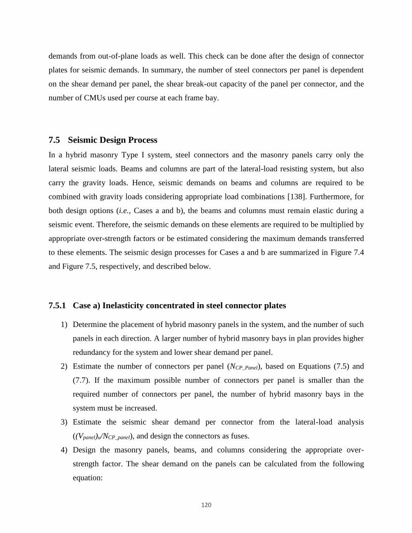
120
demands from out-of-plane loads as well. This check can be done after the design of connector
plates for seismic demands. In summary, the number of steel connectors per panel is dependent
on the shear demand per panel, the shear break-out capacity of the panel per connector, and the
number of CMUs used per course at each frame bay.
7.5 Seismic Design Process
In a hybrid masonry Type I system, steel connectors and the masonry panels carry only the
lateral seismic loads. Beams and columns are part of the lateral-load resisting system, but also
carry the gravity loads. Hence, seismic demands on beams and columns are required to be
combined with gravity loads considering appropriate load combinations [138]. Furthermore, for
both design options (i.e., Cases a and b), the beams and columns must remain elastic during a
seismic event. Therefore, the seismic demands on these elements are required to be multiplied by
appropriate over-strength factors or be estimated considering the maximum demands transferred
to these elements. The seismic design processes for Cases a and b are summarized in Figure 7.4
and Figure 7.5, respectively, and described below.
7.5.1 Case a) Inelasticity concentrated in steel connector plates
1) Determine the placement of hybrid masonry panels in the system, and the number of such
panels in each direction. A larger number of hybrid masonry bays in plan provides higher
redundancy for the system and lower shear demand per panel.
2) Estimate the number of connectors per panel (NCP_Panel), based on Equations (7.5) and
(7.7). If the maximum possible number of connectors per panel is smaller than the
required number of connectors per panel, the number of hybrid masonry bays in the
system must be increased.
3) Estimate the seismic shear demand per connector from the lateral-load analysis
((Vpanel)u/NCP_panel), and design the connectors as fuses.
4) Design the masonry panels, beams, and columns considering the appropriate over-
strength factor. The shear demand on the panels can be calculated from the following
equation:

121
0 0panel panel CP CP _ panelDD uV V V N (7.8)
The demands on columns including the seismic axial load component, and the concentrated
moments on the beams generated from the shear demand on the connector plates, must be
multiplied by the over-strength factor or be designed for the maximum load transferred to these
members from the connector plates. After estimating the demands on beams and columns, the
current code criteria [144, 145] can be used for design of these members.
7.5.2 Case b) Inelasticity concentrated in vertical bars of reinforced masonry
panels
1) Determine the placement of hybrid masonry panels in the system, and the number of such
panels in each direction. A larger number of hybrid masonry bays in plan provides higher
redundancy for the system and lower shear demand per panel.
2) Estimate the shear demand per panel at each story of the building (Vpanel)u from lateral-
load analysis.
3) Estimate the number of connectors per panel (NCP_Panel), based on Equations (7.5) and
(7.7). If the maximum possible number of steel connectors per panel is smaller than the
required number of steel connectors per panel, the number of hybrid masonry bays in the
system must be increased.
4) Design the panels according to the next section for the following demands. For flexural
design and shear design, respectively:
panel panelDF uV V (7.9)
0panel panelDV uV V (7.10)
5) Design the connector plates, beams, and columns considering the appropriate over-
strength factor or the maximum load transferred from the panel to these members. The
shear demand on a pair of connector plates can be calculated as:
0CP panel CP _ panelD uV V / N (7.11)
122
The maximum moment on a pair of connector plate can be calculated as:
CP CP CPD DM V L (7.12)
where LCP is the length of steel connectors from the through bolts to the support of the
connector plates on the beam (Figure 7.1(a)). For design of beams and columns, the demands
from gravity loads need to be added as well using appropriate load combinations [138].
7.5.3 Design of hybrid masonry structural panels
7.5.3.1 Case a) Inelasticity concentrated in steel connector plates
The story shear that can be carried by a hybrid masonry panel for Type I is the minimum of the
panel shear strength VShear, the shear force corresponding to the flexural strength VFlex, and the
shear break-out strength of the panel per steel connector multiplied by the number of connectors
per panel (Equation (6.13)). Shear strength and flexural strength of hybrid masonry panels can be
calculated per MSJC provisions for masonry shear walls [141]. Further research is required on
break-out strength of masonry panels with through bolts.
panel C Shear Flex. BO_ panel CP _ panel(V ) min(V ,V ,( V N )) (7.13)

123
Figure 7.4: Seismic design process for hybrid masonry building systems considering
connector plates with fuse behavior (Case a).
Estimate number of connectors per panel
Seismic shear demand per connector from lateral load analysis:
panelCPupanelDCP NVV _/
Design connector plates
Design masonry panels
?
?
panelCPpanelBOupanel NVV __0 /
NO
YES
NO
YES
Increase number of panels, or (and)
Increase number of connectors per panel
Determine shear force per panel (Vpanel)u from lateral load analysis
Determine the placement of hybrid masonry bays, and
Estimate preliminary number of hybrid masonry panels
41.0/_ panelpanelCP LN
Seismic shear demand on the panel:
Or from the maximum load transferred
panelCPDCPupanelDpanel NVVV _00
Design columns and beams
Combined with
demands from
gravity loads
Calculate demands on columns and beams from lateral load analysis considering over-strength factor,
or from the maximum load transferred to these
elements

124
Figure 7.5: Seismic design process for hybrid masonry building systems considering
yielding of vertical reinforcing bars in reinforced masonry panels (Case b).
Determine the placement of hybrid masonry bays, and
Estimate preliminary number of hybrid masonry panels
Estimate number of connectors per panel
Design connector plates
Design masonry panels
?
?
panelCPpanelBOupanel NVV __0 /
NO
YES
NO
YES
Increase number of panels, or (and)
Increase number of connectors per panel
Estimate shear force per panel (Vpanel)u from lateral load analysis
Design columns and beams
Combined with
demands from
gravity loads
41.0/_ panelpanelCP LN
Seismic shear demand per connector from lateral load analysis:
Or from the maximum load transferred
panelCPupanelDCP NVV _0 /
Seismic shear demand on panels: Flexural design:
Shear design:
upanelDFpanel VV
upanelDVpanel VV 0
Calculate demands on columns and beams from lateral load analysis considering over-strength factor,
or from the maximum load transferred to these
elements

125
7.5.3.2 Case b) Inelasticity concentrated in vertical bars of reinforced masonry panels
The required shear strength of a hybrid masonry panel for Type I to develop the flexural
strength, (Vpanel)CF, is obtained from Equation (7.14), and the shear strength of a hybrid masonry
panel Type I, (Vpanel)CV, is the minimum of the panel shear strength VShear, and the break-out
strength of the panel per connector times the number of connectors per panel Equation (7.15).
_( ) /panel CF C Panel panelV M h (7.14)
_ _( ) min ( , ( ))panel CV Shear BO panel CP panelV V V N (7.15)
MC_Panel, is the flexural strength of a masonry panel.
7.6 Viability of Hybrid Masonry as a Lateral-Load Resisting System
Based on the procedures described above, the feasibility of hybrid masonry panels as practical
lateral-load resisting systems is studied by calculating seismic demands on lateral-load resisting
elements of prototype buildings and designing them. The system design results are presented for
the first story, which has the maximum shear demand on the lateral-load resisting elements.
7.6.1 Description of Prototype Buildings
The prototypes studied in this research are office buildings located in Los Angeles, California,
which is a high seismic hazard region. Three, six and nine story office buildings of rectangular
plan configuration, which are 51.1 m long in the E-W direction and 36.5 m wide in the N-S
direction, are considered (Figure 7.6). Each story height is 3.7 m and 7.3 m bays are used in each
direction. Floors consist of 8.3 cm lightweight concrete placed on corrugated metal deck.
Structural steel members are wide-flange shapes comprised of A992 steel and the beams are pin-
ended. The nominal loading magnitudes are adopted from the design examples in FEMA 451
[146]: 3.0 kN/m2 for floor dead load (deck, slab, beams, girders, fireproofing, ceiling, partitions,
mechanical and electrical systems); 2.6 kN/m2 for roof dead load (roofing, insulation, deck,
beams, girders, fireproofing, ceiling, mechanical and electrical systems); 2.4 kN/m2 for office
live load; 1.2 kN/m2 for roof live load; 1.2 kN/m2 for exterior wall cladding loads (evenly

126
distributed over the exterior wall area of the buildings, including a 1.1 m high parapet wall above
the roof level); weight of the hybrid masonry panels: 4.0 kN/m2.
The design response spectrum parameters considered in the seismic design calculations are: site
class D, SS=1.5 g, S1=0.6 g, Fa=1.0, Fv=1.5, SMS=1.5 g, SM1=0.9 g, SDS=1.0, SD1=0.6, occupancy
category II (I=1.0), and redundancy factor ρ =1. The approximate equation of the code is used to
estimate the period of the prototype buildings [138].
Figure 7.6: Typical floor framing plan (dimensions in meters).
7.6.2 Design of Prototype Buildings
7.6.2.1 Case a) Inelasticity concentrated in steel connector plates
The demands on the lateral-load resisting elements are calculated considering two possible

127
values of the response modification coefficient, R = 5 and 6. The break-out strength of a panel at
one connector location is considered to be 89 kN (20 kips), based on preliminary experimental
studies by Goodnight et al. [135]. Considering W14 column section and a 64 mm (2.5 in) gap at
each side of the panel, the length of the masonry panel is 6.8 m. For this length of the panel, from
Equation (7.5), the maximum number of connectors per panel is equal to 16. The connector
plates utilized in the design are similar to the tapered fuses, detailed and tested at the University
of Hawaii [134]. The steel design is based on AISC 360-10 [144], and AISC 341-10 [145]. The
fuse illustrated in Figure 7.7(a) is designed similar to a cantilever beam subjected to a transverse
concentrated load at the tip, and is detailed so that the cross sections at the top and bottom of the
fuse reach their maximum moment capacity at the same time. Moreover, the design is based on
the provisions of Section F11 in AISC 360-10. It is assumed that the fuse is made up of steel
plates with Fy =250 MPA (36 ksi), and that the fuse length (Lf) is equal to 20 cm. The values of
the panel shear forces from lateral-load analysis are shown for 3, 6, and 9 story prototype
buildings in Table 7.2. In Table 7.2, Wr is the ratio of required number of panels to the possible
number of structural panels in each direction. The possible number of panels is equal to the
number of bays in each frame times the number of frames in each direction. Regarding the
prototype buildings considered in this study, the possible number of hybrid masonry panels in
the N-S direction is equal to 40 (see Figure 7.6). However, this number is impractical since the
building would not be functional. The parameters considered for design of the masonry panels
are listed in Table 7.3. In designing the panels, it is assumed that the vertical bars are distributed
evenly across the panel width. The shear strength of the panel can be calculated from Equation
(7.13). Other calculations are summarized in Table 7.5 to Table 7.9. The results indicate that the
system is potentially viable for the 9-story prototype office building located in a high seismic
hazard region.

128
Table 7.2: Panel shear forces from lateral-load analysis (Case a).
Base shear (kN) No. of panels in each
direction (Vpanel)u (kN)
R 3 Story 6 Story 9 Story 3 Story 6 Story 9 Story 3 Story 6 Story 9 Story
5 4517 10084 14461 7 15 21 645 672 689
6 3731 8183 11643 6 12 17 622 682 685
Note:
Wr = Ratio of required No. of panels to the
possible number of panels in the system
Wr 0.4
0.4 <Wr 0.55
Table 7.3: Parameters considered for design of reinforced masonry panels.
(a) (b)
Figure 7.7: (a) Fuse geometry. (b) Connector plate geometry (dimensions in
centimeters).
d' (mm) 50 End cover over bars
f'm (MPa) 10 Compressive strength of the masonry
fy (MPa) 414 Yield strength of the reinforcement
L (m) 6.83 Length of the panel
b (mm) 194 Thickness of the panel (8" CMU fully grouted)
h (m) 2.90 Height of the panel
Em (GPa) 9 Modulus of elasticity of masonry (900 f'm )
ES (GPa) 200 Modulus of elasticity of the reinforcement

129
7.6.2.2 Case b) Inelasticity concentrated in vertical bars of reinforced masonry panels
The demands on the lateral-load resisting elements are calculated considering four possible
values of response modification coefficient, R 3, 4, 5 and 6. Break-out strength of the panel per
connector and the length of the panels are similar to those of Case a. It is assumed that steel
connectors are made up of plates with Fy =250 MPA (36 ksi), and that the connector length, from
the center of the slotted holes to their support, is equal to 35.5 mm (Figure 7.7(b)). Results of
calculations based on the process described in the previous sections are summarized in Table 7.4
and in Section 7.8. According to the results presented in Table 7.4, for high seismic hazard
regions, using Case b is suitable for the low-rise (around 3 stories) prototype buildings.
Table 7.4: Panel shear forces from lateral-load analysis (Case b).
Base shear (kN)
No. of panels in each
direction (Vpanel)u (kN)
R 3 Story 6 Story 9 Story 3 Story 6 Story 9 Story 3 Story 6 Story 9 Story
3 8063 19750 27971 15 35 N.F. 538 564 ---
4 5847 13598 20367 11 24 36 532 567 566
5 4677 10437 15194 11 19 27 425 549 563
6 3898 8403 12152 11 15 22 354 560 552
Note:
Wr = Ratio of required No. of panels to the
possible number of panels in the system
Wr 0.4 0.55 <Wr 0.75
0.4 <Wr 0.55 0.75 < Wr<1
1.0 ≤Wr Not Feasible (N.F.)
7.7 Summary, Conclusions and Future Research
Hybrid masonry is a new system for seismic-resistant building construction. The system takes
advantage of masonry walls present in most buildings as non-structural elements, and by using
special details, makes them part of the lateral-load resisting system. A hybrid masonry system
consists of reinforced masonry panels within a steel framed structure, where steel connectors are
used to tie the surrounding steel frame to the masonry panels. To date, the system has been used
for construction of low-rise buildings in the eastern and mid-western United States. The current
research provides a framework for using one type of hybrid masonry in areas of moderate and
high seismicity. The main contributions of this study are summarized as follows:

130
Simplified lateral-load analysis of hybrid masonry Type I is presented. The results show
that the lateral-load path is straightforward and thus the system is well suited to hand
calculations.
Employing the widely-accepted capacity design concept, this study establishes the basis
for seismic design of hybrid masonry building systems, specifically those employing
hybrid masonry Type I. Seismic design methodologies for buildings incorporating hybrid
masonry Type I are discussed for two cases: inelasticity concentrated in the steel
connector plates and inelasticity concentrated in the vertical steel bars of the masonry
panels.
The viability of hybrid masonry as a new seismic lateral-load resisting system was
considered and the results of seismic demand calculations for the basic lateral-load
resisting elements show that it is a promising system. Nevertheless, there will be
significant demands on the steel connector plates for the case where plasticity is
concentrated in flexural yielding of steel vertical bars in the masonry panels. The
structural system then requires more hybrid masonry bays compared with corresponding
systems when plasticity is concentrated in steel connector plates.
When inelasticity is concentrated in the steel connector plates, mid-rise prototype office
buildings (around 9 stories) appear to be feasible. However, when inelasticity is
concentrated in the masonry panels, only low-rise buildings (around 3 stories) appear to
be feasible.
The results presented in this chapter are for prototype office buildings located on Site
Class D in a high seismic hazard region. The seismic demands on the system are smaller
for buildings located on sites with better soil conditions and in moderate seismic hazard
regions. Therefore, hybrid masonry Type I can potentially be used for taller prototype
buildings than those considered in this study.
The sample design of prototype buildings presented in this study can be used as a
practical design guide for engineers considering hybrid masonry for seismic design.
Before hybrid masonry can be effectively used as a seismic structural system, large-scale
experimental validation of the system behavior is required. This testing is planned as part of an
ongoing research project on hybrid masonry systems [127]. All hybrid masonry configurations

131
will be studied (Types I, II and III) and the critical force transfer mechanisms at the steel-
masonry interfaces will be explored. These mechanisms include masonry through-bolts (as used
for steel connectors), contact and bearing, and headed steel connectors. Validation of robust
steel-masonry interface behavior and global system performance is a critical step for
implementing hybrid masonry seismic systems.
7.8 Supplementary Materials
7.8.1 Summary of calculations for Case a)
The number of steel connectors per panel, and the shear demands per connector for the prototype
buildings are presented in Table 7.5. Table 7.6 includes moment demands and the cross-section
geometry at the top of the fuses. Moment demands and the cross-section geometry at the bottom
of fuses are presented in Table 7.7. Checks for the panel break-out strength and the shear
demands on the panels are presented in Table 7.8. A summary of shear strength for the masonry
panels using various configurations of bars is presented in Table 7.9. Since the shear break-out
strength has been checked in Table 7.8, Table 7.9 then includes the shear strength calculations
governed by flexural and shear action of the reinforced masonry panel.
Table 7.5: Number of steel connectors per panel and shear demand per connector (Case a).
(NCP_panel)min (NCP_panel)used (VCP)D (kN)
R 3 Story 6 Story 9 Story 3 Story 6 Story 9 Story 3 Story 6 Story 9 Story
5 15 16 16 16 16 16 40 42 43
6 14 16 16 16 16 16 39 43 43

132
Table 7.6: Moment demands and cross-section geometry at the top of fuses (Case a).
(MCP)D at the top of fuse
(kN-m)
Top of fuse cross section (for a single plate)
3 Story 6 Story 9 Story
R 3 Story 6 Story 9 Story Wt (mm) t (mm) Wt (mm) t (mm) Wt (mm) t (mm)
5 12.3 12.8 13.1 100 12 100 12 100 12
6 11.8 13.0 13.0 95 12 100 12 100 12
Table 7.7: Moment demands and cross-section geometry at the bottom of fuses (Case a).
(MCP)D at the bottom of fuse
(kN-m)
Bottom of fuse cross section (for a single plate)
3 Story 6 Story 9 Story
R 3 Story 6 Story 9 Story Wb (mm) t (mm) Wb (mm) t (mm) Wb (mm) t (mm)
5 4.1 4.3 4.4 55 12 60 12 60 12
6 3.9 4.3 4.3 55 12 60 12 60 12
Table 7.8: Check of panel break-out strength and shear demands on panels (Case a).
Ω0 (Vpanel)u /NCP_panel (1) (kN) VBO_panel x NCP_panel (2) (kN) (Vpanel)D =Ω0 (Vpanel)u (3) (kN)
R 3 Story 6 Story 9 Story 3 Story 6 Story 9 Story 3 Story 6 Story 9 Story
5 81 84 86 1423 1423 1423 1291 1345 1377
6 78 85 86 1423 1423 1423 1244 1364 1370
Note:
(1) The values calculated must be smaller than the break-out strength of the panel considered in the design
(See Equation (7.6)).
(2) The values calculated in this column must be greater than the shear demand on the panel (See section
“Design of hybrid masonry structural panels”).
(3) The shear demand on the panel.

133
Table 7.9: Summary of shear strength calculations of masonry panels for various configurations of
bars per MSJC 2008 Strength method.
c (1)
(cm)
Vertical
Bars
VFlex (2)
(kN)
Vm (3)
(kN)
(Vn)max (4)
(kN)
(VFlex & Shear)C (5)
(kN)
(Vs)Req. (6)
(kN)
41 11 # 4 (D13) 365 1149 1953 365 NA
82 11 # 6 (D19) 772 1149 1953 772 NA
105 11 # 7 (D22) 1011 1149 1953 1011 NA
128 11 # 8 (D25) 1262 1149 1953 1262 113
153 11 # 9 (D29) 1525 1149 1953 1525 376
Note:
Shear break-out strength has been checked in other Tables, this Table then includes the shear
strength calculations governed by flexural and shear action of the reinforced masonry panel.
(1) Length of compression zone.
(2) Flexural shear strength of the masonry panel.
(3) Shear strength provided by the masonry.
(4) Upper bound limit on the nominal shear strength of the masonry panel per MSJC 2008 [141].
(5) Shear capacity provided by flexural and shear action of the masonry panel. Comparison of these
values with shear demands per panel from Table 7.4 shows the feasibility of design of the panels for
seismic lateral-load demands.
(6) Required shear capacity of horizontal steel bars.
7.8.2 Summary of calculations for Case b)
Calculations for Case b are summarized in Table 7.10 to Table 7.12.
Table 7.10: Number of steel connectors per panel and shear demand per connector (Case b).
(NCP_panel)min (NCP_panel)used (VCP)D (kN)
R 3 Story 6 Story 9 Story 3 Story 6 Story 9 Story 3 Story 6 Story 9 Story
3 16 16 --- 16 16 --- 84 88 ---
4 15 16 16 16 16 16 83 89 88
5 12 16 16 16 16 16 66 86 88
6 10 16 16 16 16 16 55 88 86
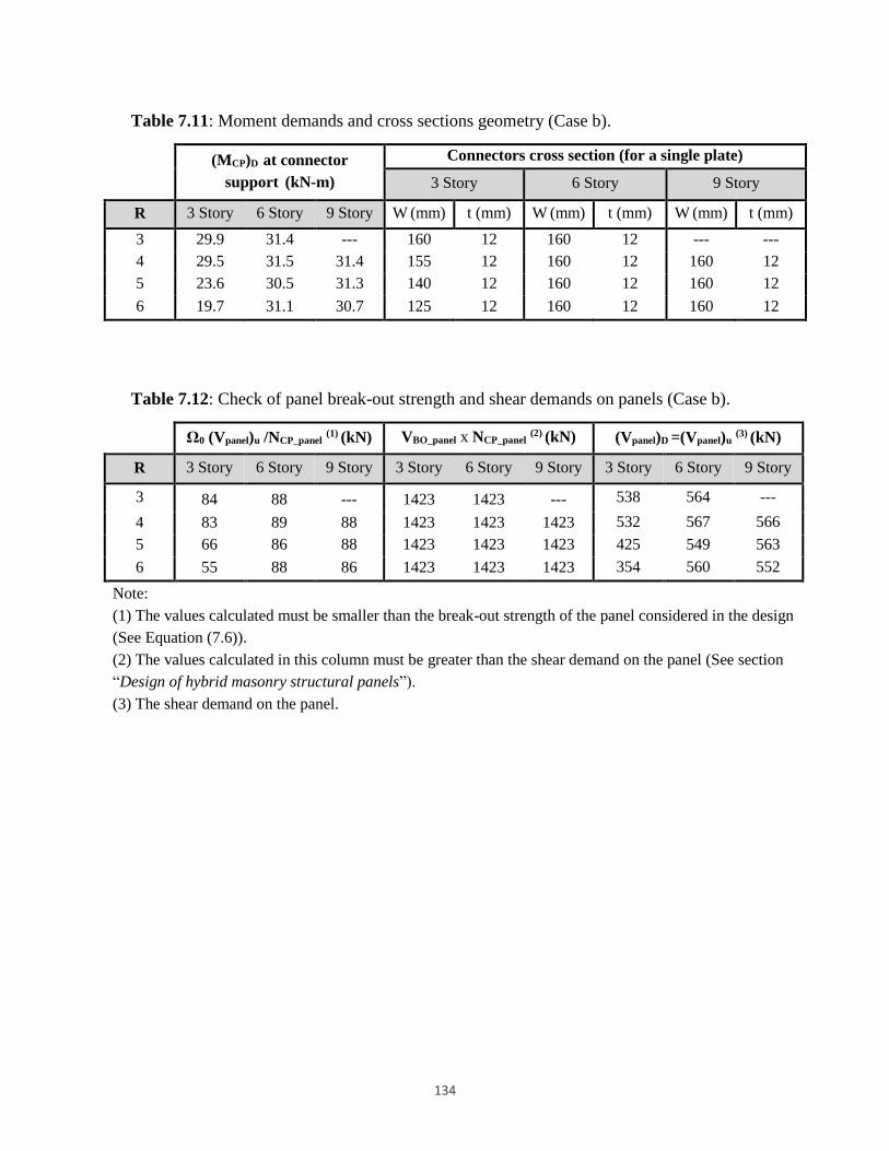
134
Table 7.11: Moment demands and cross sections geometry (Case b).
(MCP)D at connector
support (kN-m)
Connectors cross section (for a single plate)
3 Story 6 Story 9 Story
R 3 Story 6 Story 9 Story W (mm) t (mm) W (mm) t (mm) W (mm) t (mm)
3 29.9 31.4 --- 160 12 160 12 --- ---
4 29.5 31.5 31.4 155 12 160 12 160 12
5 23.6 30.5 31.3 140 12 160 12 160 12
6 19.7 31.1 30.7 125 12 160 12 160 12
Table 7.12: Check of panel break-out strength and shear demands on panels (Case b).
Ω0 (Vpanel)u /NCP_panel (1) (kN) VBO_panel x NCP_panel (2) (kN) (Vpanel)D =(Vpanel)u (3) (kN)
R 3 Story 6 Story 9 Story 3 Story 6 Story 9 Story 3 Story 6 Story 9 Story
3 84 88 --- 1423 1423 --- 538 564 ---
4 83 89 88 1423 1423 1423 532 567 566
5 66 86 88 1423 1423 1423 425 549 563
6 55 88 86 1423 1423 1423 354 560 552
Note:
(1) The values calculated must be smaller than the break-out strength of the panel considered in the design
(See Equation (7.6)).
(2) The values calculated in this column must be greater than the shear demand on the panel (See section
“Design of hybrid masonry structural panels”).
(3) The shear demand on the panel.

135
8 Capacity Spectrum-Based Seismic Design of
Type I Hybrid Masonry Structural Systems with
Fuse Connectors
Abstract
Applying the force-based seismic design procedures of the current codes to hybrid
masonry structural systems requires availability of the seismic response factors. Whereas,
hybrid masonry is a relatively new lateral-load resisting system for which seismic
response factors, including the response modification coefficient (R), are not defined in
the current codes. In this study, an integrated simple approach for performance-based
seismic analysis and design of hybrid masonry Type I systems employing fuse connector
plates is presented. The procedure used in this study is based on the Capacity Spectrum
Method. In this study, we apply the method for design of a sample hybrid masonry
building system.
Keywords: Hybrid Masonry; Capacity Spectrum; Displacement-Based Design; Capacity
Design; Performance-based Design.
8.1 Introduction
Masonry infill walls are primarily used in buildings as architectural partitions worldwide, and
their function as structural elements is usually ignored. Contrary to masonry infill panels, hybrid
masonry is a relatively new technology for earthquake resistant design of buildings, and was first

136
proposed in 2007 [125]. The system has been introduced to the eastern United States for low-rise
office and commercial buildings, but it has not been used in high-seismic regions yet.
The innovative hybrid masonry technology is based on the structural action of reinforced
masonry panels connected to a surrounding steel frame via novel steel connectors. The connector
plates if detailed appropriately can accommodate a large dissipation of energy through yielding
of the steel plates. Depending on the interfacial conditions between a masonry panel and a
surrounding frame, hybrid masonry panels are categorized into 3 major groups designated as
Types I, II, and III [126].
An overview of the current research on hybrid masonry panels is given in Abrams et al. [147].
Employing capacity design concept, seismic design methodologies for buildings incorporating
hybrid masonry panels Type I are discussed in Eidini et al. [131] (see Chapter 7) for two cases of
plasticity concentrated in steel connectors or in vertical steel bars of the masonry panels.
Seismic response factors (e.g., response modification coefficient, R) are not proposed in the
current codes for hybrid masonry systems. One advantage of performance-based design
procedures is that they are not dependent on the current codes’ seismic response factors, but on
the actual performance of the structures. To estimate the base shear of the hybrid masonry Type I
systems employing connector fuses, the current study employs a performance-based design
procedure which does not require the code-based response modification factors. The approach in
this study is an iterative process implemented in the framework of the Capacity Spectrum
Method (CSM). CSM has been widely accepted and extensively improved [148, 149, 150, 151,
152] since its recommendation in ATC-40 [153]. The steps of the approach are described in this
study. The proposed method includes an iterative process through which a hybrid masonry
structural system with fuse connector plates is designed depending on its energy dissipation
capacity. In the proposed design approach, the value of the system R factor is regulated in the
process, depending on the energy absorption capacity of the system.
8.1.1 Major Advantages of Hybrid Masonry
Hybrid masonry uses masonry walls present in most buildings as non-structural elements and by
137
employing special details makes them as parts of the lateral-load resisting system. This merit is
in accordance with a key principle of seismic resistant design of buildings as noted by Bertero
and Brokken [132]. The main advantages of hybrid masonry systems are listed as follows.
Bracing steel frames using reinforced masonry panels leads to an integrated efficient
application of both materials.
In a hybrid masonry system, moment-resisting connections or steel bracings in steel
frames are not required. Hence, making the installation of both the masonry and the
structural steel simpler, for instance by eliminating the construction difficulty in trying to
fit masonry around the braces.
Introducing the technology to engineering and research society as a new lateral load
resisting structural system rather than non-structural partitions as are in the case of infill
panels.
Removing the interaction between a masonry panel and columns, and therefore
preventing from unfavorable brittle shear failure modes of columns (e.g., reported in
[154] for the case of bounding concrete frames) by introducing gaps between a frame and
masonry panels in hybrid masonry Types I and II.
The panels can be designed to reduce the extent of the damage in the masonry, for
example via introducing the novel steel connector plates as fuses for dissipating seismic
energy [131].
Presence of the gaps both at the sides and at the top of the wall as well presence of slotted
holes in the connector plates in hybrid Type I, makes lateral-load analysis of the system
straightforward. Therefore, the system is well-suited for hand calculation [131].
The system is well-suited for a performance-based design approach, particularly for a
design philosophy in which the plasticity is concentrated in the connector plates.
Focusing on this point, the current study introduces a performance-based approach for
seismic design and analysis of hybrid masonry Type I structural systems.
Incomplete codes and lack of recommendations for seismic design of hybrid masonry systems
are among the main barriers to implement the system [147]. The current study addresses this
issue by introducing a seismic design approach which is not dependent on the code-based
seismic response factors.

138
8.2 Hybrid Masonry Type I
The paper by Eidini et al. [131] describes the force transfer mechanism in hybrid masonry Type
I. In this study, we employ an alternative approach based on the free-body diagram of a masonry
panel in Type I hybrid masonry to explain the force transfer mechanism. As described in the
current literature [131], in Type I hybrid masonry, only shear force transfers to the masonry
panel, and specifically there is no axial load transmission due to existence of gaps between the
masonry panel and the frame as well as presence of slotted holes in the steel connectors. The
story shear transfers through the steel links connecting the beam to the masonry panel (Figure 8.1
(a)).
(a) (b) (c)
Figure 8.1: (a) Hybrid masonry Type I. (b) Parameters used in lateral load analysis of
hybrid masonry Type I. (c) Free-body diagram of a masonry panel in hybrid masonry
Type I systems.
8.2.1 Lateral load analysis in hybrid masonry Type I
The free-body diagram of a masonry panel in hybrid Type I is shown in Figure 8.1(c). Beams are
pin-ended in hybrid masonry systems. Therefore, the value of moments in columns are
negligible, and are not considered in the following derivations.
The story shear at level i+1 is given by

139
1
1
n
i j
j i
V F
(8.1)
From moment equilibrium around the X-X axis in Figure 8.1(c), the axial force in the column is
given by
1 1 10X X i i i i i CP iM P L P L V h F h
1
1 1
CPi ii i i i
hhP P V F
L L
(8.2)
where CPh is the length from the slotted holes to the point of application of story forces.
Substituting Equation (8.1) in Equation (8.2), we have
1
1
1
nCPi i
i i j i
j i
hhP P F F
L L
(8.3)
Similarly, for 1iP,
2 1
1 2 2 1
CPi ii i i i
hhP P V F
L L
(8.4)
Assuming CPh is identical in all stories, and by substituting corresponding values for
1iP,
2iP, …,
nP in Equation (8.2), one can get
1 1
n n
j j j j i CPnj i j iCP
i j
j i
V h V h V hh
P FL L L
(8.5)
For very short connector plates, the last term in Equation (8.2) to Equation (8.5) can be ignored.
In RAM Element software [155] the steel connector lengths are assumed to be negligible, and
therefore the value of axial load in columns is estimated from the following formula [147, 124].
However, in realistic situations, the length of connector plates is not very small and its effect on
column axial load cannot be neglected. From Equation (8.5), the larger the length of steel

140
connectors, the larger the axial loads in columns (under lateral load). The frame and the panel
moments under lateral load are given in the following equations
1
n
Frame i j j i CPij i
M P L V h V h
(8.6)
( )Panel i p iiM V h (8.7)
Assuming that the panel height is identical in all stories and that it is approximately equal to the
story height (e.g., (hp)i=hi=h), we have
1 1
( )
n n
j j i CP j
j i j iFrame CP
Panel i p i ii
V h V h VM h
M V h V h
(8.8)
If right hand side of Equation (8.6) is constant (i.e., if lateral load pattern, steel connector length
and story heights remain unchanged throughout the stories), column axial load has an inverse
relation with the frame bay width, i.e., increasing the bay width in this case reduces the axial
load in the columns.
From Equation (8.8), the ratio of frame overturning moment to that of the panel at level i is not
dependent on L (i.e., bay width), and it depends on the lateral load pattern, length of steel
connectors and both the story and the panel heights. Additionally, Equation (8.8) shows that if
lateral load distribution pattern is scaled uniformly, the ratio does not change. However, the ratio
changes if lateral load pattern changes. For example, consider a four-story structure in which the
story height is the same in all stories, and is subjected to an inverse triangular lateral load pattern
with the magnitude equal to 1 to 4 at the 1st to 4th stories, successively. For the first story we
have
2
11
9 7 42
10
n
j
jFrame CP CP CP
Panel
VM h h h
M V h h h
(8.9)

141
Now consider a rectangular lateral load pattern producing the same base shear as that of the
inverse triangular lateral load pattern. The loading magnitude at each story will then be equal to
2.5. Hence,
2
11
7 5 5 2 51 5
10
n
j
jFrame CP CP CP
Panel
VM h h h. .
.M V h h h
(8.10)
8.2.2 Lateral stiffness of hybrid masonry Type I
In this section, using a simplified model we obtain the lateral stiffness of a hybrid masonry Type
I structural system. In the system, each masonry panel is connected in series with the steel
connectors (Figure 8.2(a)). Hence, for a single panel, the displacement of the panel is given by
Pij Cij Mij (8.11)
in which the indices i and j represent the bays and stories numbers, respectively. Also, the
indices P, C and M denote panel (hybrid panel), connectors and masonry panel, successively.
From the above relation we have
Pij Cij Mij
V V V
K K K (8.12)
1 1 1
Pij Cij MijK K K (8.13)
The steel connectors per each panel are acting in parallel with each other. Hence, the lateral
stiffness of the connectors per panel at bay i and story j,CijK , can be estimated as
_
_
1
( )CP panelN
Cij CP CP panel CPK K N K (8.14)
From Equation (8.13), in a single hybrid masonry panel, the total stiffness of the masonry panel
and connectors acting in series is dominated by the more flexible element, i.e., the connector

142
plates which are much more flexible than the masonry panels. Hence, for a single panel, lateral
stiffness of the hybrid panel can be considered equal to that of the connectors as given in the
following.
Pij CijK K (8.15)
Figure 8.2: (a) Schematic connection of a hybrid masonry panel to steel connectors. (b)
Schematic connection of elements in a two-story and three-bay hybrid masonry Type I
building system. Cij represents the steel connectors in the ith bay and jth story, and Mij
stands for the masonry panel in the ith bay and jth story. SFj represents the steel frame at
the jth story.
The schematic connections of the structural elements in a two-story and three-bay hybrid
masonry Type I building system is illustrated in Figure 8.2(b). The lateral stiffness of the jth
story can be estimated as
. .
1 1
No of HM bays No of HM bays
Sj Pij SFj Cij SFj
i i
K K K K K
(8.16)
where SFjK is the stiffness of the steel frame at the jth story. Assuming the steel beams have
pinned ends, and disregarding the stiffness of the frame, we have
.
_
1
( )No of HM bays
Sj CP panel CP i
i
K N K
(8.17)

143
Assuming only one type of steel connector is used at each story, we have
.
_ _
1
( ) ( ) ( )No of HM bays
Sj CP CP panel i CP Story j CP j
i
K K N N K
(8.18)
in which (NCP_Story)j is the number of steel connectors at the jth story. The relation above shows
that in a system with long hybrid masonry bays in which the steel connectors are much more
flexible than the masonry panel, the number and the stiffness of connector plates control the
story stiffness. Note that the relation above is true on the basis of the assumptions that the steel
frame does not contribute in the lateral stiffness and that the connector plates are much more
flexible than the masonry panels. By considering the steel beams as pin-ended and designing the
connector plates as energy absorption fuses, the realistic situation can be close to the assumed
one.
8.3 Performance-based Seismic Design of Hybrid Masonry Structural Systems
In this section, a performance-based design approach is proposed for seismic analysis and design
of hybrid masonry Type I systems. The design methodology is based on formation of the plastic
hinges in the connector plates, i.e., case (a) described by Eidini et al. [131] (see Chapter 7). The
main assumptions used in the proposed design process are summarized as follows:
Plastic hinges only form in the connector plates. This assumption is accommodated
through capacity design of the system described by Eidini et al. [131].
To obtain the story displacement, only connector plates are considered and the
displacements of the masonry panels are ignored (rotation of the masonry panels and the
flexural and shear displacement of the panel are small compared to the deformation of the
connectors, and are neglected in the calculations).
Only one type of connector plate is used at each story, i.e., the geometry and load-
displacement behavior of all connector plates are the same (this assumption simplifies the
design process).
144
The performance-based seismic design procedure presented in this study is an iterative process
based on CSM. The process is illustrated in Figure 8.3. The steps of the proposed CSM-based
approach for seismic design of hybrid masonry Type-I systems with fuse connector plates are
given in the following.
1) Estimate the base shear. Assume a value for R factor (force reduction factor), and
calculate lateral load demand for preliminary design stage. R=6 is suggested at this stage.
2) Design the system based on the steps for case (a) described by Eidini et al. [131].
3) Construct the earthquake response spectrum in acceleration displacement (A-D) format.
To convert a spectrum from the Sa-T format to A-D format use the following relation.
g
TS i
di ai2
2
S 4
(8.19)
4) Construct the capacity curve of the system in terms of the base shear versus roof
displacement. As described in Section 8.2.2, almost all lateral shear is resisted by the
system of connector plates and the masonry panel. Moreover, the connector plates per
each panel are acting in parallel whose resultant system is performing in series with the
masonry panel. Hence, given the load-displacement curve for the connector plates, the
capacity curve of the system can be constructed in terms of base shear versus roof
displacement. The process is illustrated in Figure 8.4 and Figure 8.5. Therefore, we have
_( )Panel u CP CP panelCapacityV F N
(8.20)
in which (VPanel)Capacity is the shear capacity of each hybrid masonry panel; (Fu)CP is the
ultimate shear load capacity of a connector plate. Story shear can then be calculated from the
sum of shear capacity of the panels at each story.
Story Panel Capacity
V V (8.21)
5) Convert the capacity curve of the system to that of a single degree of freedom (SDOF)
representation in A-D format. The conversion is carried out via the following formula.
1
iai
V / WS
(8.22)

145
1 1
roof
di
roof ,
SPF
(8.23)
where (Sai, Sdi) are points on capacity spectrum curve corresponding to (Vi, ∆roof) on the
capacity curve of the system. 1 and PF1 are the mass and modal participation factors of the
first mode, respectively; ϕroof,1 is amplitude of the first mode at the roof level; V is base shear;
W is the dead load plus probable live load; ∆roof is the roof displacement; Sa is the spectrum
acceleration; Sd is the spectrum displacement.
N
1i
2
1i
1
2
1
1
1
/w
/
gg
w
gw
i
N
i
i
N
i
ii
/w
/
1
2
1i
1
1
1 N
i
i
N
i
ii
g
gw
PF
(8.24)
6) Draw the demand versus capacity curve in A-D format in a single plot.
7) Determine the performance point, i.e., the intersection of the demand with the capacity
curve. The performance point obtained in this way is for a SDOF system which needs to
be converted to that of a multi-degree of freedom (MDOF) system.
8) Evaluate performance of the structure. If the performance point is before and close to the
end point of the capacity curve, i.e., it meets the following relation, go to the next step;
otherwise the system design needs to be verified.
toleranced
dd
p
pe
0
(8.25)
where de and dp are ultimate and performance point displacements, respectively. In this study
0.05 is used as the tolerance.
9) Check code displacement limit criteria. If OK, design the system for the demand on each
elements; otherwise use less ductile connector plates and go to Step 3.

146
Figure 8.3: CSM-based design of hybrid masonry Type I building systems with fuse
connector plates.
Determine the number of panels and connector plates based on the steps described for Case a
YES
Estimate the base shear
Construct the A-D
format of the
earthquake spectrum
construct the capacity curve of the system (base shear versus
roof displacement)
Convert the capacity curve of the system to that of a SDOF system
in A-D format
Draw the demand versus capacity in A-D format in a single plot.
Determine the performance point
Determine demands on panels, columns, beams, and
connections and design them (see Case a in Eidini et al. 2013)
?
Capacity curve intersects with the
demand curve
Use more ductile connector plates and (or) increase
the number of connector plates
Use less ductile connector plates
NO
Preliminary
Design
?
Code displacementcheck
YES
NO
Transform the displacement demand from
SDOF to that of MDOF system
?
05.00
p
pe
d
ddYES
Use less ductile connector plates and (or) decrease
the number of connector plates
NO
End

147
(a) (b) (c)
Figure 8.4: (a) Envelope curve derived from the test results; (b) load-displacement curve
for a hybrid masonry panel Type-I; (c) Story shear-displacement curve for a frame
employing hybrid masonry Type-I panels.
Figure 8.5: Base shear versus roof displacement.
8.4 Description of a Prototype Building
The example considered for this section is a three-story office building located in a moderate
seismic hazard region. The building has a rectangular plan configuration with 21.9 m long in the
E-W direction and 21.9 m wide in the N-S direction (Figure 8.6). Each story height is 3.7 m.
They are framed in structural steel with 7.3 m bays in each direction. Floors include 8.3 cm
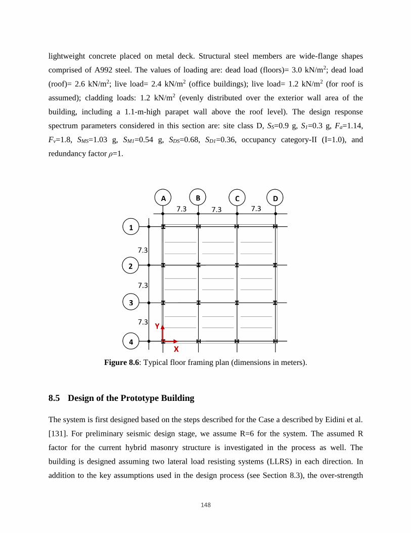
148
lightweight concrete placed on metal deck. Structural steel members are wide-flange shapes
comprised of A992 steel. The values of loading are: dead load (floors)= 3.0 kN/m2; dead load
(roof)= 2.6 kN/m2; live load= 2.4 kN/m2 (office buildings); live load= 1.2 kN/m2 (for roof is
assumed); cladding loads: 1.2 kN/m2 (evenly distributed over the exterior wall area of the
building, including a 1.1-m-high parapet wall above the roof level). The design response
spectrum parameters considered in this section are: site class D, SS=0.9 g, S1=0.3 g, Fa=1.14,
Fv=1.8, SMS=1.03 g, SM1=0.54 g, SDS=0.68, SD1=0.36, occupancy category-II (I=1.0), and
redundancy factor ρ=1.
Figure 8.6: Typical floor framing plan (dimensions in meters).
8.5 Design of the Prototype Building
The system is first designed based on the steps described for the Case a described by Eidini et al.
[131]. For preliminary seismic design stage, we assume R=6 for the system. The assumed R
factor for the current hybrid masonry structure is investigated in the process as well. The
building is designed assuming two lateral load resisting systems (LLRS) in each direction. In
addition to the key assumptions used in the design process (see Section 8.3), the over-strength
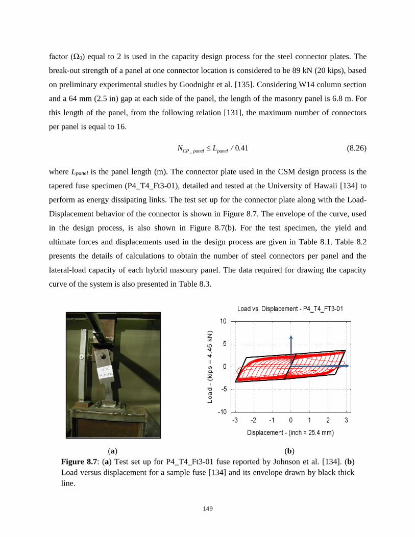
149
factor (Ω0) equal to 2 is used in the capacity design process for the steel connector plates. The
break-out strength of a panel at one connector location is considered to be 89 kN (20 kips), based
on preliminary experimental studies by Goodnight et al. [135]. Considering W14 column section
and a 64 mm (2.5 in) gap at each side of the panel, the length of the masonry panel is 6.8 m. For
this length of the panel, from the following relation [131], the maximum number of connectors
per panel is equal to 16.
0 41CP _ panel panelN L / . (8.26)
where Lpanel is the panel length (m). The connector plate used in the CSM design process is the
tapered fuse specimen (P4_T4_Ft3-01), detailed and tested at the University of Hawaii [134] to
perform as energy dissipating links. The test set up for the connector plate along with the Load-
Displacement behavior of the connector is shown in Figure 8.7. The envelope of the curve, used
in the design process, is also shown in Figure 8.7(b). For the test specimen, the yield and
ultimate forces and displacements used in the design process are given in Table 8.1. Table 8.2
presents the details of calculations to obtain the number of steel connectors per panel and the
lateral-load capacity of each hybrid masonry panel. The data required for drawing the capacity
curve of the system is also presented in Table 8.3.
(a) (b)
Figure 8.7: (a) Test set up for P4_T4_Ft3-01 fuse reported by Johnson et al. [134]. (b)
Load versus displacement for a sample fuse [134] and its envelope drawn by black thick
line.

150
Table 8.1: Critical points of hysteretic response for the fuse used in the design.
Yield Point Ultimate Point
∆y
mm
Fy
kN
∆u
mm
Fu
kN
5.3 6.7 73.7 13.3
Table 8.2: The number of steel connectors used per panel and lateral-load capacity of
each hybrid masonry panel.
Table 8.3: The data needed to draw the capacity curve of the system.
dR R Y (8.27)
Level(V u )LLRS
(1)
kN
N panel(2)
(V u )panel(3)
kN
N CP_panel(4)
Required
N CP_panel(5)
min
N CP_panel(6)
Used
(V C )panel(7)
kN
3 88.4 2 44.2 2 1 3 80
2 161.3 2 80.7 4 2 6 160
1 197.8 3 65.9 3 2 7 187
Note:
(1) Lateral-load demand on each LLRS. The structures include two LLRS.
(2) Number of hybrid masonry panels at each level per LLRS.
(3) Lateral-load demand per each hybrid masonry panel.
(4) Required number of steel connectors per panel.
(5) Minimum number of steel connectors per panel from Equation (6.7).
(6) Used number of steel connectors per panel.
(7) Lateral-load capacity of each panel.
Level(V u-LLRS )C
kN
(∆ u )CP
mm
(D Story )u
mm
(V y-LLRS )C
kN
(∆ y )CP
mm
(D Story )u
mm
3 160.1 2.9 8.7 80.1 0.21 0.63
2 320.3 2.9 5.8 160.1 0.21 0.42
1 560.5 2.9 2.9 280.2 0.21 0.21
Note:
=∆u/∆y= 13.8 R=(2-1)= 5.16
d= 2 R= 10

151
where R and d are the ductility reduction and over-strength factors, respectively, as given by
the following relations [156, 143]. The parameterY is the allowable stress factor [156].
e
y
VR
V
y
d
d
V
V (8.28)
For the structures designed based on the ultimate strength method, the allowable stress factor is
equal to unity. Hence, the response reduction factor is given by
dR R (8.29)
For intermediate period range, and from the equal energy criterion we have [143]
2 1R (8.30)
Considering 0 2d , we have
R 2 2 1 (8.31)
Assuming the first mode is the predominant mode of the system, capacity curve of the system is
converted to that of a SDOF representation in A-D format [153]. Furthermore, the demand and
capacity curves are drawn in A-D format in a single plot. To obtain the demand curve, the
earthquake spectrum needs to be reduced. The reduction factors account for the energy dissipated
by the structure during a seismic event. The spectrum reduction factors are used as follows
3 21 0 68
2 12
eff
A
. . Ln SR
.
(8.32)
2 31 0 41
1 65
eff
V
. . Ln SR
.
(8.33)
In the above formula, SRA and SRV are spectral reduction values in constant acceleration and
constant velocity ranges of the spectrum, respectively; eff, is the effective damping of the
structure, which combines the inherent viscous damping and hysteretic damping. It can be
calculated from the following relation [153]:

152
0
63 75 5
y p y p
eff
p p
. a d d a
a d
(8.34)
in which, 0, is the viscous damping equivalent to the hysteretic damping; 0.05, is the assumed
inherent viscous damping of the structure; (dy, ay) and (dp, ap) are the coordinates of the yield and
performance points, respectively (see Figure 8.8); Performance point is located on the
intersection of the demand and capacity curves and is determined via an iterative procedure
[153]. The parameter is a damping modification factor introduced in ATC 40 for existing
Reinforced Concrete (RC) structures. The factor is dependent on the structural behavior. In ATC
40, structural behavior is also categorized based on quality of the lateral load resisting system
and duration of the ground motion. The structure under investigation is a newly designed hybrid
masonry building, and not a RC structure. For this example, since inelasticity is concentrated to
the steel connector fuses, a higher ductility than that of an existing RC structure, and
consequently a higher factor than that suggested in ATC 40 are expected. For the current
example, the same factor as in the ATC 40 for the structures of category A is used, which is
conservative.
The performance point, i.e., the intersection of the demand with the capacity curve, is then
determined. The performance point obtained in this way is for a SDOF system that needs to be
converted to that of a MDOF system.
The demand versus capacity curve in A-D format, for the example system, is presented in Figure
8.9. The figure shows that the system provides sufficient capacity and the performance point is
(0.1 g, 6.8 in).

153
Figure 8.8: Bilinear representation of the capacity spectrum and the key points in
damping calculation.
Figure 8.9: Final iteration result. The dotted black line (2nd Iteration) matches well with
the green line. Therefore, performance point is shown by a solid black circle in the figure.
8.6 Concluding Remarks and Future Research
A Capacity Spectrum Method-based seismic design approach has been proposed for hybrid
masonry Type I structural systems with fuse connectors. Advantages of hybrid masonry Type I
along with the straightforward implementation of the performance based design approaches for
0
0.1
0.2
0.3
0.4
0.5
0.6
0.7
0.8
0 5 10 15 20 25
S a (g
)
Sd (in)

154
fuse-based hybrid masonry panels, offer an interesting solution for seismic design of these types
of structures.
The proposed approach is capable of providing an estimate of the seismic demands, e.g., the
force and displacement demands on a hybrid masonry Type I structure with fuse connectors
without performing a nonlinear push-over analysis. In this regard, as a substitute for nonlinear
push-over analysis, we obtain the capacity curve of the system via knowing the load-
displacement behavior of the connector plates. Moreover, using the test results carried out on
connector plates at the University of Hawaii, the application of the method is presented for
analysis and design of an example system. The proposed method is for the structures in which
the first mode is the predominant mode of the structure. Hence, it is suitable for low and mid-rise
buildings. Based on the study by Eidini et al. [131], hybrid masonry Type I is also applicable to
low and mid-rise buildings.
In addition to the advantages of displacement-based design approaches cited in the literature
[157], the major benefits of the proposed approach are as follows:
The method is an interactive seismic analysis and design procedure which is not
dependent on the code proposed seismic response factors, but rather on the performance
of the system.
The preliminary design is only dependent on the design of the fuses. Therefore, less effort
is needed compared with the application of the performance-based design approaches on
other structures.
Before the proposed method can be effectively used, several issues must be addressed as listed in
the following.
In this study, the spectrum reduction factors have been chosen based on the proposed
values in the ATC40. However, a higher reduction factor is expected due to the higher
ductility of the Type I hybrid masonry with fuse connectors. More research is required on
the appropriate reduction factor for this type of the structure.
Only one type of steel connector plate has been used in the design process. For the
effective application of the proposed method, availability of the database on the load-

155
displacement relationships for steel connector plats is necessary.
The length of the slotted holes in the connector plates is required to be sufficient to
accommodate the story drifts during a seismic event. Otherwise, the axial load will be
transferred to the connector plates.
Under lateral load a hybrid masonry panel may fail due to the lack of strength in either
in-plane or out-of-plane directions. This study only addresses the in-plane behavior of the
panels.
The push-over curves are obtained based on the assumption that the steel frame does not
contribute in the lateral stiffness. Effect of the stiffness of the continuous columns on the
lateral stiffness of the system, even though small, needs to be investigated.
For the case of the panels with small bay lengths, the effect of the stiffness of the
masonry panels on the lateral stiffness must be investigated.
Base shear capacity is only dependent on the first story connector plates! Force-
displacement curves of the other stories need to be checked separately.
As an alternative, fix the displacement (target displacement) and calculate the demand
accordingly. Start with a target displacement and a value for ductility. Then, calculate the
acceleration demand (base shear). Iteration is not needed in this approach.
Perform the pushover analysis of the structures considering the effect of the columns in
the frame, and compare the result with the simplified model proposed in the current work.
In this regard, the nonlinear force-displacement, obtained numerically for the connector
plate used in the proposed design procedure, has been compared and calibrated to match
with the corresponding force-displacement curve obtained from experimental test (see
Figure 8.10). Hence, it can be used for further investigations of the behavior of the
prototype structures using a nonlinear analysis.

156
Figure 8.10: Load versus displacement for a sample fuse obtained experimentally shown
by red line [134] versus the corresponding plot obtained from computational simulation
performed by OpenSees.

157
Appendix A: Artworks Related to the BCH2 Pattern
Figure A.1: Novel artworks related to the BCH2 pattern. Figure shows different positions
of a kinetic structure.

158
References
[1] H. C. Greenberg, M. L. Gong, S. P. Magleby and L. L. Howell, "Identifying links between origami
and compliant," Mechanical Sciences (Open Access), p. 217–225, 2011.
[2] J. Vincent, "Deployable structures in nature," in Deployable Structures, New York, Springer-Verlag
Wien, 2001, pp. 37-51.
[3] K. Miura and M. Natori, "2-D Array Experiment on Board a Space," Space Power, vol. 5, p. 345–
356, 1985.
[4] K. Miura, "Concepts of deployable space structures," International Journal of Space Structures,
vol. 8, no. 1, pp. 3-16, 1993.
[5] K. Kuribayashi, K. Tsuchiya, Z. You, D. Tomus, M. Umemoto, T. Ito and M. Sasaki, "Self-
deployable origami stent grafts as a biomedical application of Ni-rich TiNi shape memory alloy
foil," Materials Science and Engineering: A, vol. 419, no. 1-2, pp. 131-137, 2006.
[6] A. Heller, "A Giant Leap for Space Telescopes," Science and Technology by Lawrence Livermore
National Laboratory, pp. 12-18, 2003.
[7] E. Elsayed and B. B. Basily, "A continuous folding process for sheet materials," International
Journal of Materials and Product Technology, vol. 21, pp. 217-238, 2004.
[8] C. Cromvik, "Numerical Folding of Airbags Based on Optimization and Origami," Chalmers
University of Technology and Goteborg University, Goteborg , 2007.
[9] J. Ma and Z. You, "Energy Absorption of Thin-Walled Square Tubes With a Prefolded Origami
Pattern—Part I: Geometry and Numerical Simulation," Journal of Applied Mechanics, vol. 81, p.
011003, 2014.
[10] M. Schenk and S. D. Guest, "Geometry of Miura-folded metamaterials," Proceedings of the
National Academy of Sciences, vol. 110, no. 9, pp. 3276-3281, 2013.
[11] S. D. Guest and S. Pellegrino, "Inextensional Wrapping of Flat Membranes," in Proceedings of the
First International Seminar on Structural Morphology, Montpellier, 1992.
[12] T. Fukuchi, "Nagata Acoustics News," 25 December 2002. [Online]. Available:
http://www.nagata.co.jp/news/news0212-e.htm.
[13] K. Fuchi, J. Tang, B. Crowgey, A. R. Diaz, E. J. Rothwell and R. O. Ouedraogo, "Origami Tunable
Frequency Selective Surfaces," Antennas and Wireless Propagation Letters, IEEE, vol. 11, pp. 473-
475, 2012.
[14] K. Kuribayashi and Z. You, "Deployable Stent". US Patent 7,060,092, 2006.

159
[15] K. Miura and T. Tachi, "Synthesis of rigid-foldable cylindrical polyhedra," Journal of the
International Society for the Interdisciplinary Study of Symmetry (ISIS-Symmetry), no. Special Issue
for the Festival-Congress, Gmünd, Austria, pp. 204-213, 2010.
[16] S. Heimbs, "Foldcore sandwich structures and their impact behaviour: An overview," in Dynamic
Failure of Composite and Sandwich Structures, Springer Netherlands, 2013, pp. 491-544.
[17] A. Hanaor and R. Levy, "Evaluation of Deployable Structures for Space Enclosures," Int. J. Space
Struct., vol. 16, no. 4, pp. 211-229, 2001.
[18] N. Friedman, G. Farkas and A. Ibrahimbegovic, "Deployable/retractable structures towards
sustainable development," Pollack Periodica, vol. 6, no. 2, p. 85–97, 2011.
[19] R. Kronenburg, Flexible: architecture that responds to change, Laurence King, 2007.
[20] T. Tachi, Architectural Origami - Architectural Form Design Systems based on Computational
Origami, Lecture notes for MIT 6.849, 2010.
[21] A. E. Del Grosso and P. Basso, "Adaptive building skin structures," Smart Materials and
Structures, vol. 19, no. 12, p. 124011, 2010.
[22] Y. Chen and J. Feng, "Folding of a Type of Deployable Origami Structures," International Journal
of Structural Stability and Dynamics, vol. 12, no. 6, p. 1250054, 2012.
[23] M. Schenk and S. Guest, "Origami folding: A structural engineering approach," in Origami 5: Fifth
International Meeting of Origami Science, Mathematics, and Education (5OSME), 2011.
[24] K. Miura, "Method of packaging and deployment of large membranes in space," in 31st Congress
of the International Astronautical Federation, Japan Aerospace Exploration Agency, Tokyo, 1980.
[25] R. D. Resch and H. Christiansen, "The design and analysis of kinematic folded plate systems," in
Proceedings of IASS Symposium on Folded Plates and Prismatic Structures, 1970.
[26] T. Tachi, M. Masubuchi and M. Iwamoto, "Rigid Origami Structures with Vacuumatics: Geometric
Considerations," [Online]. Available: http://origami.c.u-
tokyo.ac.jp/~tachi/cg/VacuumaticOrigamiIASS2012.pdf. [Accessed August 2015].
[27] K. Miura, "Proposition of pseudo-cylindrical concave polyhedral shells," in Proceedings of IASS
Symposium on Folded Plates and Prismatic Structures, 1970.
[28] F. Heinzelmann, "Lightweight origami structure & daylighting modulation," in Proceedings of the
IASS Symposium, Valencia, 2009.
[29] "Abu Dhabi Investment Council Headquarters (Al Bahr Towers)," ARUP, [Online]. Available:
http://www.arup.com/projects/abu_dhabi_investment_council_headquarters/adic_gallery1.aspx.

160
[30] D. A. Huffman, "Curvature and creases: A primer on paper," IEEE Transaction on Computers, vol.
25, pp. 1010-1019, 1976.
[31] K. Miura, "A Note on Intrinsic Geometry of Origami, 6–7 December," in Proc. 1st Int. Meet. of
Origami Science, Ferrara, Italy, 1989.
[32] T. Hull, in Project Origami, AK Peters, 2006, p. 229–235.
[33] N. Watanabe and K. Kawaguchi, "The method for judging rigid foldability," in Origami4:
Proceedings of the Fourth International Conference on Origami in Science, Mathematics, and
Education, 2009.
[34] T. Tachi, "Simulation of rigid origami," in R.J. Lang, ed., Origami 4: Fourth International Meeting
of Origami Science, Mathematics, and Education (4OSME), 175-188, 2009.
[35] S. M. Belcastro and T. C. Hull, "Modelling the folding of paper into three dimensions using affine
transformations," Linear Algebra and its Applications, vol. 348, pp. 273-282, 2002.
[36] S. Krishnan, "The Christian Science Monitor," 17 September 2003. [Online]. Available:
http://www.csmonitor.com/2003/0917/p01s03-woap.html. [Accessed 6 March 2014].
[37] Z. Wu, I. Hagiwara and X. Tao, "Optimisation of crush characteristics of the cylindrical origami
structure," International Journal of Vehicle Design, vol. 43, no. 1-4, pp. 66-81, 2007.
[38] H. Engel, Structure Systems, Praeger, foreword by Ralph Rapson, 1968.
[39] Z. Y. Wei, Z. V. Guo, L. Dudte, H. Y. Liang and L. Mahadevan, "Geometric mechanics of periodic
pleated origami," Physical Review Letters, vol. 110, no. 21, pp. 215501-215505, 2013.
[40] A. Norman, K. Seffen and S. Guest, "Morphing of Curved Corrugated Shells," Int. J. Solids
Structures, vol. 46, no. 7-8, pp. 1624-1633, 2009.
[41] K. A. Seffen, "Compliant Shell Mechanisms," Philosophical Transactions of the Royal Society of
London A: Mathematical, Physical and Engineering Sciences, vol. 370, no. 1965, pp. 2010-2026,
2012.
[42] K. Fuchi, A. R. Diaz, E. J. Rothwell, R. O. Ouedraogo and J. Tang, "An origami tunable
metamaterial," Journal of Applied Physics, vol. 111, no. 8, p. 084905, 2012.
[43] "Resonant Chamber," [Online]. Available: http://archinect.com/firms/project/14483206/resonant-
chamber/45313996.
[44] C. L. Randall, E. Gultepe and D. H. Gracias, "Self-folding devices and materials for biomedical
applications," Trends in biotechnology, vol. 30, no. 3, pp. 138-146, 2012.
[45] L. Ionov, "Soft microorigami: self-folding polymer films," Soft Matter, vol. 7, no. 15, pp. 6786-

161
6791, 2011.
[46] E. G. Rapp, "Sandwich-type structural element". United States of America Patent 2,963,128, 6
December 1960.
[47] G. A. Sehrndt, "Verbundplatte und Verfahren zu ihrer Herstellung". DD Patent 1434112, 1960.
[48] K. Miura, "Map fold a la Miura style, its physical characteristics and application to the space
science," Research of Pattern Formation, no. ed R Takaki (Tokyo: KTK), pp. 77-90, 1994.
[49] M. Schenk, S. D. Guest and G. J. McShane, "Novel stacked folded cores for blast-resistant
sandwich beams," International Journal of Solids and Structures, vol. 51, no. 25, pp. 4196-4214,
2014.
[50] J. L. Silverberg, A. A. Evans, L. McLeod, R. C. Hayward, T. Hull, C. D. Santangelo and I. Cohen,
"Using origami design principles to fold reprogrammable mechanical metamaterials," Science , vol.
345, no. 6197, pp. 647-650, 2014.
[51] S. Li and K. W. Wang, "Fluidic origami cellular structure--combining the plant nastic movements
with paper folding art," in Proceedings SPIE 9431, Active and Passive Smart Structures and
Integrated Systems, San Diego, California, United States, 2015.
[52] A. Brunner, "Expansible Surface Structure". United States of America Patent 3362118, 9 January
1968.
[53] Z. You and K. Kuribayashi, "Expandable tubes with negative Poisson’s ratio and their application
in medicine," in Origami4: Fourth International Meeting of Origami Science, Mathematics, and
Education, 2009.
[54] J. Ma and Z. You, "Modelling of the Waterbomb Origami Pattern and its Applications," in
Proceedings of the ASME 2014 International Design Engineering Technical Conferences and
Computers and Information in Engineering Conference (IDETC/CIE), Buffalo, New York, USA,
2014.
[55] D.-Y. Lee, J.-S. Kim, S.-R. Kim, J.-S. Koh and K.-J. Cho, "The Deformable Wheel Robot Using
Magic-Ball Origami Structure," in Proceedings of the ASME 2013 International Design
Engineering Technical Conferences & Computers and Information in Engineering Conference,
IDETC/CIE, Oregon, 2013.
[56] "Archinet," [Online]. Available: http://archinect.com/firms/project/14483206/resonant-
chamber/45313996.
[57] H. U. Buri, "Origami - Folded Plate Structures; PhD Thesis," École Polytechnique Fédérale De
Lausanne, 2010.
[58] R. H. Knapp, "Pseudo-cylindrical shells: A new concept for undersea structures," Journal of
Engineering for Industry, vol. 99, no. 2, pp. 485-492, 1977.

162
[59] I. Katsuhiro, M. Ishinabe, S. Kobayashi, H. Matsubayashi and Y. Nishimura, "Packing can". US
Patent 5,100,017, 31 March 1992.
[60] H. Buri and Y. Weinand, "ORIGAMI-folded plate structures, architecture," in 10th World
Conference on Timber Engineering, 2008.
[61] H. Khalilpasha and A. F, "Textured deep subsea pipelines," International Journal of Mechanical
Sciences, vol. 68, pp. 224-235, 2013.
[62] T. Tachi and K. Miura, "Rigid-Foldable Cylinders and Cells," Journal of the International
Association for Shell and Spatial Structures (IASS), vol. 53, no. 4, pp. 217-226, 2012.
[63] K. C. Cheung, T. Tachi, S. Calisch and K. Miura, "Origami interleaved tube cellular materials,"
Smart Materials and Structures , vol. 23, no. 9, p. 094012, 2014.
[64] T. Nojima and K. Saito, "Development of newly designed ultra-light core structures," JSME
International Journal Series A, vol. 49, no. 1, pp. 38-42, 2006.
[65] M. Eidini and G. H. Paulino, "Unravelling Metamaterial Properties in Zigzag-base Folded Sheets,"
Science Advances, vol. 1, no. 8, p. e1500224, 2015.
[66] E. A. Peraza-Hernandez, D. J. Hartl, R. J. Malak Jr and D. C. & Lagoudas, "Origami-inspired active
structures: a synthesis and review," Smart Materials and Structures , vol. 23, no. 9, p. 094001,
2014.
[67] B. H. Hanna, J. M. Lund, R. J. Lang, S. P. Magleby and L. L. Howell, "Waterbomb base: a
symmetric single-vertex bistable origami mechanism," Smart Materials and Structures, vol. 23, no.
9, p. 094009, 2014.
[68] K. Miura, "Zeta-Core Sandwich - Its Concept and Realization," Inst. of Space and Aeronautical
Science, University of Tokyo, vol. 480, pp. 137-164, 1972.
[69] F. Haas and R. J. Wootton, "Two basic mechanisms in insect wing folding," Proceedings of the
Royal Society of London.Series B: Biological Sciences, vol. 263, pp. 1651-1658, 1996.
[70] H. Kobayashi, B. Kresling and J. F. V. Vincent, "The geometry of unfolding tree leaves,"
Proceedings of the Royal Society of London.Series B: Biological Sciences, vol. 265, pp. 147-154,
1998.
[71] L. Mahadevan and S. Rica, "Self-organized origami," Science, vol. 307, p. 1740, 2005.
[72] B. Audolya and A. Boudaoud, "Buckling of a stiff film bound to a compliant substrate—Part III:
Herringbone solutions at large buckling parameter," J. Mech. Phys. Solids, vol. 56, pp. 2444-2458,
2008.
[73] K. Miura, "The science of Miura-ori: a review," in 4th International Meeting of Origami Science,
Mathematics, and Education, RJ Lang, Ed., AK Peters, 2009.

163
[74] X. Chen and J. W. Hutchinson, "Herringbone buckling patterns of compressed thin films on
compliant substrates," Journal of Applied Mechanics, vol. 71, pp. 597-603, 2004.
[75] M. B. Amar and F. Jia, "Anisotropic growth shapes intestinal tissues during embryogenesis,"
Proceedings of the National Academy of Sciences, vol. 110, no. 26, pp. 10525-10530, 2013.
[76] A. E. Shyer, T. Tallinen, N. L. Nerurkar, Z. Wei, E. S. Gil, D. L. Kaplan, C. J. Tabin and L.
Mahadevan, "Villification: how the gut gets its villi," Science, vol. 342, no. 6155, pp. 212-218,
2013.
[77] J. Ginepro and T. C. Hull, "Counting Miura-ori foldings," Journal of Integer Sequences, vol. 17, no.
2, p. 14.10.8, 2014.
[78] C. Lv, D. Krishnaraju, G. Konjevod, H. Yu and H. Jiang, "Origami based Mechanical
Metamaterials," Scientific Reports, vol. 4, p. 5979, 2014.
[79] "ART.COM," [Online]. Available: http://www.art.com.
[80] "Garden Centre Online," [Online]. Available: http://www.gardencentreonline.co.uk/1-meter-of-
hornbeam-hedging-plants-carpinus-betulus-4-plants.html#prettyPhoto/0/. [Accessed 4 March 2014].
[81] T. Tachi, "One-DOF cylindrical deployable structures with rigid quadrilateral panels," in
Symposium of the International Association for Shell and Spatial Structures, Valencia, 2009.
[82] D. Balkcom, "Robotic origami folding," 2004.
[83] W. McGuire, R. H. Gallagher and R. D. Ziemian, Matrix Structural Analysis, New York: Wiley,
2000.
[84] N. Bassik, G. M. Stern and D. H. Gracias, "Microassembly based on hands free origami with
bidirectional curvature," Applied physics letters, vol. 95, no. 9, p. 091901, 2009.
[85] K. Saito, F. Agnese and F. Scarpa, "A cellular kirigami morphing wingbox concept," Journal of
intelligent material systems and structures 22, vol. 22, no. 9, pp. 935-944, 2011.
[86] F. Scarpa, M. Ouisse, M. Collet and K. Saito, "Kirigami auxetic pyramidal core: mechanical
properties and wave propagation analysis in damped lattice," Journal of Vibration and Acoustics ,
vol. 135, no. 4, p. 041001, 2013.
[87] Y. Hou, R. Neville, F. Scarpa, C. Remillat, B. Gu and M. Ruzzene, "Graded conventional-auxetic
Kirigami sandwich structures: Flatwise compression and edgewise loading," Composites Part B:
Engineering, vol. 59, pp. 33-42, 2014.
[88] A. Alderson and K. L. Alderson, "Auxetic Materials," Proceedings of the Institution of Mechanical
Engineers, Part G: Journal of Aerospace Engineering, vol. 221, no. 4, pp. 565-575, 2007.

164
[89] R. Lakes, "Foam structures with a negative Poisson's ratio," Science, vol. 235, no. 4792, pp. 1038-
1040, 1987.
[90] T. C. T. Ting and T. Chen, "Poisson's ratio for anisotropic elastic materials can have no bounds,"
The quarterly journal of mechanics and applied mathematics, vol. 58, no. 1, pp. 73-82, 2005.
[91] A. Alderson, K. L. Alderson, G. Chirima, N. Ravirala and K. M. Zied, "The in-plane linear elastic
constants and out-of-plane bending of 3-coordinated ligament and cylinder-ligament honeycombs,"
Composites Science and Technology , vol. 70, no. 7, pp. 1034-1041, 2010.
[92] T. Lim, "On simultaneous positive and negative Poisson's ratio laminates," physica status solidi (b)
, vol. 244, no. 3, pp. 910-918, 2007.
[93] S. Felton, M. Tolley, E. Demaine, D. Rus and R. Wood, "A method for building self-folding
machines," Science , vol. 345, no. 6197 , pp. 644-646, 2014.
[94] M. Eidini, "Zigzag-base folded sheet cellular mechanical metamaterials," Under Review.
[95] K. Miura, "The science of miura-ori," in 4th International Meeting of Origami Science,
Mathematics, and Education, RJ Lang, Ed., AK Peters, 2009.
[96] K. Tanizawa and K. Miura, "Large displacement configurations of bi-axially compressed infinite
plate," Japan Society for Aeronautical and Space Sciences, Transactions, vol. 20, pp. 177-187,
1978.
[97] M. Schenk and S. D. Guest, "Geometry of miura-folded metamaterials," Proceedings of the
National Academy of Sciences, vol. 110, no. 9, pp. 3276-3281, 2013.
[98] Z. T. M. Song, R. Tang, Q. Cheng, X. Wang, D. Krishnaraju, R. Panat, C. K. Chan, H. Yu and H.
Jiang, "Origami lithium-ion batteries," Nature communications, vol. 5, p. 3140 , 2014.
[99] T. Tachi, "Generalization of rigid foldable quadrilateral mesh origami," in Proc. of the Int.
Association for Shell and Spatial Structures (IASS) Symp, Valencia, Spain, 2009.
[100] F. Gioia, D. Dureisseix, R. Motro and B. Maurin, "Design and analysis of a foldable/unfoldable
corrugated architectural curved envelop," Journal of Mechanical Design, vol. 134, no. 3, p. 031003,
2012.
[101] S. Heimbs, "Foldcore sandwich structures and their impact behaviour: An overview," in Dynamic
Failure of Composite and Sandwich Structures, Springer Netherlands, 2013, pp. 491-544.
[102] K. E. Evans and A. Alderson, "Auxetic materials: functional materials and structures from lateral
thinking!," Advanced materials , vol. 12, no. 9, pp. 617-628, 2000.
[103] W. Yang, Z.-M. Li, W. Shi, B.-H. Xie and M.-B. Yang, "Review on auxetic materials," Journal of
materials science, vol. 39, no. 10, pp. 3269-3279, 2004.

165
[104] A. Alderson and K. L. Alderson, "Auxetic Materials," Proceedings of the Institution of Mechanical
Engineers, Part G: Journal of Aerospace Engineering, vol. 221, no. 4, pp. 565-575, 2007.
[105] J. N. Grima, A. Alderson and K. E. Evans, "Auxetic behaviour from rotating rigid units," Physica
status solidi (b), vol. 242, no. 3, pp. 561-575, 2005.
[106] J. N. Grima, V. Zammit, R. Gatt, A. Alderson and K. E. Evans, "Auxetic behaviour from rotating
semi‐rigid units," Physica Status Solidi (b) , vol. 244, no. 3, pp. 866-882, 2007.
[107] D. Prall and R. S. Lakes, "Properties of a chiral honeycomb with a Poisson's ratio of -1,"
International Journal of Mechanical Sciences, vol. 39, no. 3, pp. 305-314, 1997.
[108] A. Spadoni and M. Ruzzene, "Elasto-static micropolar behavior of a chiral auxetic lattice," Journal
of the Mechanics and Physics of Solids, vol. 60, no. 1, pp. 156-171, 2012.
[109] R. F. Almgren, "An isotropic three-dimensional structure with Poisson's ratio -1," Journal of
Elasticity , vol. 15, no. 4, pp. 427-430, 1985.
[110] K. E. Evans, A. Alderson and F. R. Christian, "Auxetic two-dimensional polymer networks. An
example of tailoring geometry for specific mechanical properties," J. Chem. Soc., Faraday Trans.,
vol. 91, no. 16, pp. 2671-2680, 1995.
[111] H. Yasuda and J. Yang, "Reentrant Origami-Based Metamaterials with Negative Poisson’s Ratio
and Bistability," Physical Review Letters, vol. 114, no. 18, p. 185502, 2015.
[112] K. Bertoldi, P. M. Reis, S. Willshaw and T. Mullin, "Negative Poisson's ratio behavior induced by
an elastic instability," Advanced Materials, vol. 22, no. 3, pp. 361-366, 2010.
[113] S. Babaee, J. Shim, J. C. Weaver, E. R. Chen, N. Patel and K. Bertoldi, "3D soft metamaterials with
negative Poisson's ratio," Advanced Materials, vol. 25, no. 36, pp. 5044-5049, 2013.
[114] Y. Cho, J.-H. Shin, A. Costa, T. A. Kim, V. Kunin, J. Li, S. Y. Lee, S. Yange, H. Nam Hanf, I.-S.
Choi and D. J. Srolovitze, "Engineering the shape and structure of materials by fractal cut,"
Proceedings of the National Academy of Sciences , vol. 111, no. 49, pp. 17390-17395, 2014.
[115] Z. Wang and H. Hu, "3D auxetic warp‐knitted spacer fabrics," physica status solidi (b), vol. 251,
no. 2, pp. 281-288, 2014.
[116] M. Glazzard and P. Breedon, "Weft-knitted auxetic textile design," Physica Status Solidi (b), vol.
251, no. 2, pp. 267-272, 2014.
[117] H. Kobayashi, B. Kresling and J. F. V. Vincent, "The geometry of unfolding tree leaves,"
Proceedings of the Royal Society of London. Series B: Biological Sciences, vol. 265, pp. 147-154,
1998.
[118] J. A. Rogers, T. Someya and Y. Huang, "Materials and mechanics for stretchable electronics,"
Science, vol. 327, no. 5973, pp. 1603-1607, 2010.

166
[119] Y. Zhang, Y. Huang and J. A. Rogers, "Mechanics of stretchable batteries and supercapacitors,"
Current Opinion in Solid State and Materials Science, 2015.
[120] A. Lamoureux, K. Lee, M. Shlian, S. R. Forrest and M. Shtein, "Dynamic kirigami structures for
integrated solar tracking," Nature communications, p. 6:8092, 2015.
[121] T. Castle, Y. Cho, X. Gong, E. Jung, D. M. Sussman, S. Yang and R. D. Kamien, "Making the cut:
Lattice kirigami rule," Physical review letters, vol. 113, no. 24, p. 245502, 2014.
[122] J. M. Gattas, W. Wu and Z. You, "Miura-Base Rigid Origami: Parameterizations of First-Level
Derivative and Piecewise Geometries," Journal of Mechanical Design, vol. 135, no. 11, p. 111011,
2013.
[123] S. A. Zirbel, R. J. Lang, M. W. Thomson, D. A. Sigel, P. E. Walkemeyer, B. P. Trease, S. P.
Magleby and L. L. Howell, "Accommodating thickness in origami-based deployable arrays,"
Journal of Mechanical Design, vol. 135, no. 11, p. 111005, 2013.
[124] M. Eidini and D. P. Abrams, "Lateral force distributions for various types of hybrid masonry
panels," in Proceedings of the Eleventh North American Masonry Conference, Minneapolis,
Minnesota, USA, 2011.
[125] D. T. Biggs, "Hybrid Masonry Structures," in Proceedings of the Tenth North American Masonry
Conference, Boulder, Colorado, USA, 2007.
[126] NCMA, "Hybrid concrete masonry design, TEK 14-9A," National Concrete Masonry Association ,
Herndon, Virginia, USA, 2009.
[127] D. P. Abrams, "NSF NEESR research on hybrid masonry seismic structural systems," in
Proceedings of the Eleventh North American Masonry Conference, Minneapolis, Minnesota, USA,
2011.
[128] R. Elements, Bentley RAM Elements , Version 10.7.0.17, 2010.
[129] L. L. Pook and J. L. Dawe, "Effects of Interface conditions Between a Masonry Shear Panel and
Surrounding Steel Frame," in Proceedings of the Forth Canadian Masonry Symposium, 1986.
[130] J. L. Dawe and C. K. Seah, "Behavior of masonry infilled steel frames," Canadian Journal of Civil
Engineering, pp. 865-876, 1989.
[131] M. Eidini, D. Abrams and L. Fahnestock, "Seismic Design and Viability of Hybrid Masonry
Building Systems," J. Struct. Eng., vol. 139, no. 3, pp. 411-421, 2013.
[132] V. Bertero and S. Brokken, "Infills in seismic resistant building," Journal of Structural
Engineering, vol. 109, no. 6, p. 1337–1361, 1983.
[133] NCMA, "Hybrid concrete masonry construction details, TEK 3-3B," National Concrete Masonry
Association, Herndon, Virgina, USA, 2009.

167
[134] G. Johnson, I. N. Robertson, S. Goodnight and R. Ozaki-Train, "Behavior of energy dissipating
connectors and fuses," in Proceedings of the Eleventh North American Masonry Conference,
Minneapolis, MN, 2011.
[135] S. R. Goodnight, P. Johnson G and I. N. Robertson, "Connector development for hybrid masonry
seismic structural systems, Research Report UHM/CEE/11-03," University of Hawaii, Manoa, HI,
2011.
[136] R. Ozaki-Train and I. N. Robertson, "Hybrid masonry connector development and design, Research
Report UHM/CEE/11-04," University of Hawaii, Manoa, HI, 2011.
[137] T. Paulay and M. J. N. Priestley, Seismic Design of Reinforced Concrete and Masonry Buildings,
New York: Wiley, 1992.
[138] ASCE, "Minimum design loads for buildings and other structures - ASCE/SEI 7-10 (2010)," ASCE,
Reston, VA, 2010.
[139] D. P. Abrams, "A set of class notes for a course in masonry structures," Department of Civil and
Environmental Engineering, Univ. of Illinois at Urbana-Champaign, Urbana, IL, 2009.
[140] P. Soroushian, K. Obaseki and K. Choi, "Non-linear modeling and seismic analysis of masonry
shear walls," Journal of Structural Engineering, vol. 114, no. 5, p. 1106–1119, 1988.
[141] MSJC, "Building Code Requirements for Masonry Structures (ACI 530-05/ASCE 5-05/TMS 402-
05)," The Masonry Society (TMS), Boulder, CO, 2008.
[142] C.-M. Uang, M. Bruneau, A. S. Whittaker and K.-C. Tsai, "Seismic design of steel structures," in
The Seismic Design Handbook, 2 ed., F. Naeim, Ed., Boston, Kluwer Academic Publishers, 2001,
pp. 409-462.
[143] A. S. Elnashai and L. Di Sarno, Fundamentals of earthquake engineering, New York: Wiley, 2008.
[144] AISC, "Specification for Structural Steel Buildings - ANSI/AISC 360-10," American Institute of
Steel Construction, Chicago, 2010.
[145] AISC, "Seismic Provisions for Structural Steel Buildings - ANSI/AISC 341-10," American Institute
of Steel Construction, Chicago, 2010.
[146] FEMA, "Structural steel design. Chapter 5, NEHRP recommended provisions: Design examples,"
Building Seismic Safety Council, National Institute of Building Sciences, Washington, DC, 2006.
[147] D. P. Abrams, L. A. Fahnestock and M. Eidini, "Basic mechanisms for hybrid masonry structures,"
in Proceedings of the 2010 ASCE Structures Congress, 2010.
[148] A. K. Chopra and R. K. Goel, "Capacity-demand-diagram methods based on inelastic design
spectrum," Earthquake spectra, vol. 15, no. 4, pp. 637-656, 1999.

168
[149] P. Fajfar, "Capacity spectrum method based on inelastic demand spectra," Earthquake Engineering
& Structural Dynamics, vol. 28, no. 9, pp. 979-993, 1999.
[150] S. A. Freeman, "The Capacity Spectrum Method as a Tool for Seismic Design," in Proceedings of
the 11th European conference on earthquake engineering, 1998.
[151] S. A. Freeman, "Review of the development of the capacity spectrum method," ISET Journal of
Earthquake Technology, vol. 41, no. 1, pp. 1-13, 2004.
[152] C. Casarotti and R. Pinho, "An adaptive capacity spectrum method for assessment of bridges
subjected to earthquake action," Bulletin of Earthquake Engineering, vol. 5, no. 3, pp. 377-390,
2007.
[153] ATC, "Seismic Evaluation and Retrofit of Concrete Buildings," ATC 40, Applied Technology
Council, Redwood City, CA, 1996.
[154] G. Al-Chaar, "Evaluating strength and stiffness of unreinforced masonry infill structures. Report
No. ERDC/CERL TR-02-1," U.S. Army Corps of Engineers, Champaign, IL, 2002.
[155] RAM, Bentley RAM Elements , Version 10.7.0.17, 2010.
[156] M. R. Maheri and R. Akbari, "Seismic behaviour factor, R, for steel X-braced and knee-braced RC
buildings," Engineering structures, vol. 25, no. 12, pp. 1505-1513, 2003.
[157] M. S. Medhekar and D. J. L. Kennedy, "Displacement-based seismic design of buildings-theory,"
Engineering structures, vol. 22, no. 3, pp. 201-209, 2000.