˘ ˇ ˆ - library.e.abb.com · To make the testing procedure eas-ier, ... BFP, provides backup...
32
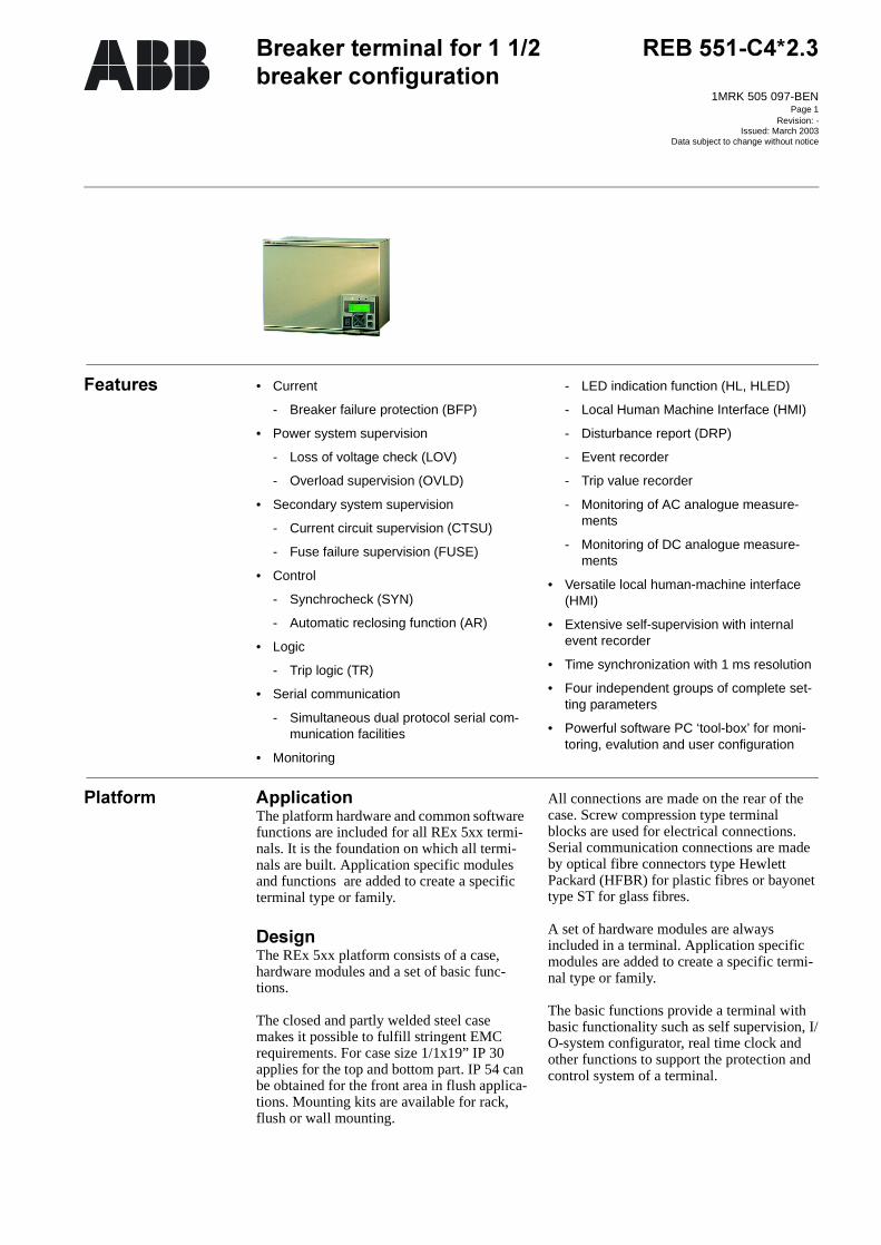
Page 1 5(%& %UHDNHUWHUPLQDOIRU EUHDNHU FRQILJXUDWLRQ 1MRK 505 097-BEN Revision: - Issued: March 2003 Data subject to change without notice )HDWXUHV • Current - Breaker failure protection (BFP) • Power system supervision - Loss of voltage check (LOV) - Overload supervision (OVLD) • Secondary system supervision - Current circuit supervision (CTSU) - Fuse failure supervision (FUSE) • Control - Synchrocheck (SYN) - Automatic reclosing function (AR) • Logic - Trip logic (TR) • Serial communication - Simultaneous dual protocol serial com- munication facilities • Monitoring - LED indication function (HL, HLED) - Local Human Machine Interface (HMI) - Disturbance report (DRP) - Event recorder - Trip value recorder - Monitoring of AC analogue measure- ments - Monitoring of DC analogue measure- ments • Versatile local human-machine interface (HMI) • Extensive self-supervision with internal event recorder • Time synchronization with 1 ms resolution • Four independent groups of complete set- ting parameters • Powerful software PC ‘tool-box’ for moni- toring, evalution and user configuration 3ODWIRUP $SSOLFDWLRQ The platform hardware and common software functions are included for all REx 5xx termi- nals. It is the foundation on which all termi- nals are built. Application specific modules and functions are added to create a specific terminal type or family. 'HVLJQ The REx 5xx platform consists of a case, hardware modules and a set of basic func- tions. The closed and partly welded steel case makes it possible to fulfill stringent EMC requirements. For case size 1/1x19” IP 30 applies for the top and bottom part. IP 54 can be obtained for the front area in flush applica- tions. Mounting kits are available for rack, flush or wall mounting. All connections are made on the rear of the case. Screw compression type terminal blocks are used for electrical connections. Serial communication connections are made by optical fibre connectors type Hewlett Packard (HFBR) for plastic fibres or bayonet type ST for glass fibres. A set of hardware modules are always included in a terminal. Application specific modules are added to create a specific termi- nal type or family. The basic functions provide a terminal with basic functionality such as self supervision, I/ O-system configurator, real time clock and other functions to support the protection and control system of a terminal.
Transcript of ˘ ˇ ˆ - library.e.abb.com · To make the testing procedure eas-ier, ... BFP, provides backup...
1MRK 505 097-BEN
Page 1
Revision: -Issued: March 2003Data subject to change without notice
• Current
- Breaker failure protection (BFP)
• Power system supervision
- Loss of voltage check (LOV)
- Overload supervision (OVLD)
• Secondary system supervision
- Current circuit supervision (CTSU)
- Fuse failure supervision (FUSE)
• Control
- Synchrocheck (SYN)
- Automatic reclosing function (AR)
• Logic
- Trip logic (TR)
• Serial communication
- Simultaneous dual protocol serial com-munication facilities
• Monitoring
- LED indication function (HL, HLED)
- Local Human Machine Interface (HMI)
- Disturbance report (DRP)
- Event recorder
- Trip value recorder
- Monitoring of AC analogue measure-ments
- Monitoring of DC analogue measure-ments
• Versatile local human-machine interface (HMI)
• Extensive self-supervision with internal event recorder
• Time synchronization with 1 ms resolution
• Four independent groups of complete set-ting parameters
• Powerful software PC ‘tool-box’ for moni-toring, evalution and user configuration
!""The platform hardware and common software functions are included for all REx 5xx termi-nals. It is the foundation on which all termi-nals are built. Application specific modules and functions are added to create a specific terminal type or family.
#The REx 5xx platform consists of a case, hardware modules and a set of basic func-tions.
The closed and partly welded steel case makes it possible to fulfill stringent EMC requirements. For case size 1/1x19” IP 30 applies for the top and bottom part. IP 54 can be obtained for the front area in flush applica-tions. Mounting kits are available for rack, flush or wall mounting.
All connections are made on the rear of the case. Screw compression type terminal blocks are used for electrical connections. Serial communication connections are made by optical fibre connectors type Hewlett Packard (HFBR) for plastic fibres or bayonet type ST for glass fibres.
A set of hardware modules are always included in a terminal. Application specific modules are added to create a specific termi-nal type or family.
The basic functions provide a terminal with basic functionality such as self supervision, I/O-system configurator, real time clock and other functions to support the protection and control system of a terminal.

1MRK 505 097-BEN
Page 2
#"Common functions are the software functions that always are included in the terminals.
$%&'$()*
!""Use the time synchronization source selector to select a common source of absolute time for the terminal when it is a part of a protec-tion system. This makes comparison of events and disturbance data between all ter-minals in a system possible.
%Two main alternatives of external time syn-chronization are available. Either the syn-chronization message is applied via any of the communication ports of the terminal as a telegram message including date and time, or as a minute pulse, connected to a binary input. The minute pulse is used to fine tune already existing time in the terminals.
The REx 5xx terminal has its own internal clock with date, hour, minute, second and millisecond. It has a resolution of 1 ms.
The clock has a built-in calendar that handles leap years through 2098. Any change between summer and winter time must be handled manually or through external time synchronization. The clock is powered by a capacitor, to bridge interruptions in power supply without malfunction.
The internal clock is used for time-tagging disturbances, events in Substation monitoring system (SMS) and Substation control system (SCS), and internal events.
+"', *
!""Use the four sets of settings to optimize the terminals operation for different system con-ditions. By creating and switching between fine tuned setting sets, either from the human-machine interface or configurable binary inputs, results in a highly adaptable terminal that can cope with a variety of system scenar-ios.
%The GRP function block has four functional inputs, each corresponding to one of the set-ting groups stored within the terminal. Acti-
vation of any of these inputs changes the active setting group. Four functional output signals are available for configuration pur-poses, so that continuous information on active setting group is available.
+'-)(*
!""Unpermitted or uncoordinated changes by unauthorized personnel may cause severe damage to primary and secondary power cir-cuits. Use the setting lockout function to pre-vent unauthorized setting changes and to control when setting changes are allowed.
By adding a key switch connected to a binary input a simple setting change control circuit can be built simply allowing only authorized keyholders to make setting changes from the built-in HMI.
%Activating the setting restriction prevents unauthorized personell to purposely or by mistake change terminal settings.
The HMI--BLOCKSET functional input is configurable only to one of the available binary inputs of a REx 5xx terminal. For this reason, the terminal is delivered with the default configuration, where the HMI--BLOCKSET signal is connected to NONE-NOSIGNAL.
The function permits remote changes of set-tings and reconfiguration through the serial communication ports. The setting restrictions from remote can be activated only from the local HMI.
All other functions of the local human-machine communication remain intact. This means that an operator can read all distur-bance reports and other information and set-ting values for different protection parameters and the configuration of different logic cir-cuits.
(.%/&01'(. *
!""The I/O system configurator must be used in order for the terminal’s software to recognize added modules and to create internal address mappings between modules and protections and other functions.

1MRK 505 097-BEN
Page 3
+"0'(2$*
!""Use the local HMI, SMS or SCS to view the status of the self-supervision function. The self-supervision operates continuously and includes:
• Normal micro-processor watchdog func-tion
• Checking of digitized measuring signals
• Checksum verification of PROM contents and all types of signal communication
3
!""The user can with the available logic function blocks build logic functions and configure the terminal to meet application specific require-ments.
Different protection, control, and monitoring functions within the REx 5xx terminals are quite independent as far as their configuration in the terminal is concerned. The user can not change the basic algorithms for different functions. But these functions combined with the logic function blocks can be used to cre-ate application specific functionality.
(0'(24*The inverter function block INV has one input and one output, where the output is in inverse ratio to the input.
.'.*The OR function is used to form general combinatory expressions with boolean vari-ables. The OR function block has six inputs and two outputs. One of the outputs is inverted.
!2#'!2#*The AND function is used to form general combinatory expressions with boolean vari-ables.The AND function block has four inputs and two outputs. One of the inputs and one of the outputs are inverted.
$'$)*The function block TM timer has drop-out and pick-up delayed outputs related to the input signal. The timer has a settable time delay (parameter T).
$'$3*The function block TL timer with extended maximum time delay at pick-up and at drop-
out, is identical with the TM timer. The dif-ference is the longer time delay.
'$ *The pulse function can be used, for example, for pulse extensions or limiting of operation of outputs. The pulse timer TP has a settable length.
511&"'$6*The function block TQ pulse timer with extended maximum pulse length, is identical with the TP pulse timer. The difference is the longer pulse length.
50.'7.*The exclusive OR function XOR is used to generate combinatory expressions with bool-ean variables. The function block XOR has two inputs and two outputs. One of the out-puts is inverted. The output signal is 1 if the input signals are different and 0 if they are equal.
+/&%'+*The Set-Reset (SR) function is a flip-flop that can set or reset an output from two inputs respectively. Each SR function block has two outputs, where one is inverted.
+/&%'+)*The Set-Reset function SM is a flip-flop with memory that can set or reset an output from two inputs respectively. Each SM function block has two outputs, where one is inverted. The memory setting controls if the flip-flop after a power interruption will return the state it had before or if it will be reset.
',$*The GT function block is used for controlling if a signal should be able to pass from the input to the output or not depending on a set-ting.
+'$+*The function block TS timer has outputs for delayed input signal at drop-out and at pick-up. The timer has a settable time delay. It also has an Operation setting On, Off that controls the operation of the timer.
1
!""The protection and control terminals have a complex configuration with many included functions. To make the testing procedure eas-ier, the terminals include the feature to indi-

1MRK 505 097-BEN
Page 4
vidually block a single, several or all functions.
This means that it is possible to see when a function is activated or trips. It also enables
the user to follow the operation of several related functions to check correct functional-ity and to check parts of the configuration etc.
"' *
!""In many protection applications local redun-dancy is used. One part of the fault clearance system is however never duplicated, namely the circuit breaker. Therefore a breaker fail-ure protection can be used.
The breaker failure protection is initiated by trip signals from different protection func-tions within or outside the protection termi-nal. When a trip signal is sent to the breaker failure protection first, with no or a very short delay, a re-trip signal can be sent to the pro-tected breaker. If fault current is flowing through the breaker still after a setting time a back-up trip signal is sent to the adjacent breakers. This will ensure fault clearance also if the circuit breaker is out of order.
%Breaker failure protection, BFP, provides backup protection for the primary circuit breaker if it fails to clear a system fault. It is obtained by checking that fault current per-sists after a brief time from the operation of the object protection and issuing then a three phase trip command to the adjacent circuit breakers (back-up trip).
Correct operation at evolving faults is ensured by phase segregated starting com-mand, phase segregated current check and phase segregated settable timers.
Additionally, the retrip of the faulty circuit breaker after a settable time is possible. The retrip can be controlled by current check or carried out as direct retrip.
/%"0
30&'3.4*
!""The loss of voltage detection, LOV, is suit-able for use in networks with an automatic restoration function. The LOV function issues a three-pole trip command to the cir-cuit breaker, if all three phase voltages fall below the set value for a time longer than 7 seconds, and the circuit breaker remains closed.
%The operation of LOV function is based on line voltage measurement. The function is provided with a logic, which automatically recognises if the line was restored for at least three seconds before starting the seven sec-onds timer. Additionally, the function is auto-matically blocked if only one or two phase voltages have been detected low for more than 10 seconds. The LOV function operates again only if the line has been fully energised.
Operation of LOV function is also inhibited by fuse failure and open circuit breaker infor-mation signals, by their connection to dedi-cated inputs of the function block.
The operation of the function is supervised by the fuse-failure function and the information
about the closed position of the associated circuit breaker.
.01"0'.43#*
!""The overload protection, OVLD, prevents excessive loading of power transformers, lines and cables.
Alternative application is the detection of pri-mary current transformer overload, as they usually can withstand a very small current beyond the rated value.
%The function continuously measures the three phase currents flowing through the terminal. If any of the three currents is beyond the pre-set overcurrent threshold for a time longer than the preset value, a trip signal is acti-vated.
#11'#3#*
!""The main purpose of the dead line detection is to provide different protection, control and monitoring functions with the status of the

1MRK 505 097-BEN
Page 5
line, i.e whether or not it is connected to the rest of the power system.
%The dead line detection function continuously measures all three phase currents and phase
voltages of a protected power line. The line is declared as dead (not energized) if all three measured currents and voltages fall below the preset values for more than 200 ms.
+1%%"0
"0'$+8*
!""Faulty information about current flows in a protected element might influence the secu-rity (line differential protection) or depend-ability (line distance protection) of a complete protection system.
The main purpose of the current circuit super-vision function is to detect different faults in the current secondary circuits and influence the operation of corresponding main protec-tion functions.
The signal can be configured to block differ-ent protection functions or initiate an alarm.
%The function compares the sum of the three phase currents from one current transformer core with a reference zero sequence current from another current transformer core.
The function issues an output signal when the difference is greater than the set value.
"0'8+*
!""The fuse failure supervision function, FUSE, continuously supervises the ac voltage cir-cuits between the voltage instrument trans-formers and the terminal. Different output signals can be used to block, in case of faults in the ac voltage secondary circuits, the oper-ation of the distance protection and other
voltage-dependent functions, such as the syn-chro-check function, undervoltage protection, etc.
Different measurement principles are avail-able for the fuse failure supervision function.
The FUSE function based on zero sequence measurement principle, is recommended in directly or low impedance earthed systems.
%The FUSE function based on the zero sequence measurement principle continu-ously measures the zero sequence current and voltage in all three phases. It operates if the measured zero sequence voltage increases over preset operating value, and if the mea-sured zero sequence current remains below the preset operating value.
Three output signals are available. The first depends directly on the voltage and current measurement. The second depends on the operation of the dead line detection function, to prevent unwanted operation of the distance protection if the line has been deenergised and energised under fuse failure conditions. The third depends on the loss of all three measured voltages. A special function input serves the connection to the auxiliary contact of a miniature circuit breaker, MCB (if used), to secure correct operation of the function on simultaneous interruption of all three mea-sured phase voltages also when the additional delta current and delta voltage algorithm is not present in the function block.
+%&&'+92*
!""The main purpose of the synchrocheck func-tion is to provide controlled closing of circuit breakers in interconnected networks.
The main purpose of the energizing check function is to facilitate the controlled recon-nection of a disconnected line or bus to, respectively, an energized bus or line.
To meet the different application arrange-ments, a number of identical SYN function blocks may be provided within a single termi-nal. The number of these function blocks that may be included within any given terminal depends on the type of terminal. Therefore, the specific circuit breaker arrangements that can be catered for, or the number of bays of a specific arrangement that can be catered for, depends on the type of terminal.

1MRK 505 097-BEN
Page 6
%The synchrocheck function measures the con-ditions across the circuit breaker and com-pares them to set limits. The output is only given when all measured conditions are simultaneously within their set limits.
The energizing check function measures the bus and line voltages and compares them to both high and low threshold detectors. The output is only given when the actual mea-sured conditions match the set conditions.
For single circuit breaker and 1 1/2 circuit breaker arrangements, the SYN function blocks have the capability to make the neces-sary voltage selection. For single circuit breaker arrangements, selection of the correct voltage is made using auxiliary contacts of the bus disconnectors. For 1 1/2 circuit breaker arrangements, correct voltage selec-tion is made using auxiliary contacts of the bus disconnectors as well as the circuit break-ers (as well as binary output signals from the other terminals in the same diameter for 1 1/2 circuit breaker applications with a separate terminal per circuit breaker).
!'!*
!""The majority of power line faults are transient in nature, i.e. they do not recur when the line is re-energized following disconnection. The main purpose of the AR automatic reclosing function is to automatically return power
lines to service following their disconnection for fault conditions.
Especially at higher voltages, the majority of line faults are single-phase-to-earth. Faults involving all three phases are rare. The main purpose of the single- and two-pole automatic reclosing function, operating in conjunction with a single- and two-pole tripping capabil-ity, is to limit the effect to the system of faults involving less than all three phases. This is particularly valuable for maintaining system stability in systems with limited meshing or parallel routing.
%The AR function is a logical function built up from logical elements. It operates in conjunc-tion with the trip output signals from the line protection functions, the OK to close output signals from the synchrocheck and energizing check function, and binary input signals. The binary input signals can be for circuit breaker position/status or from other external protec-tion functions.
Of the six reclosing programs, one provides for three-pole reclosing only, while the others provide for single- and two-pole reclosing as well. For the latter, only the first shot may be single- or two-pole. All subsequent shots up to the maximum number will be three-pole. For some of the programs, depending on the initial trip, no shot, or only one shot, will be permitted irrespective of the number of shots selected.
3 $"'$*
!""The main purpose of the TR trip logic func-tion is to serve as a single node through which all tripping for the entire terminal is routed.
The main purpose of the single- and two-pole extension to the basic three-pole tripping function is to cater for applications where, for reasons of system stability, single-pole trip-ping is required for single-phase faults, and/or two-pole tripping is required for two-phase faults, e.g. on double circuit parallel lines.
%The minimum duration of a trip output signal from the TR function is settable.
The TR function has a single input through which all trip output signals from the protec-tion functions within the terminal, or from external protection functions via one or more of the terminal’s binary inputs, are routed. It has a single trip output for connection to one or more of the terminal’s binary outputs, as well as to other functions within the terminal requiring this signal.
The expanded TR function for single- and two-pole tripping has additional phase segre-gated inputs for this, as well as inputs for faulted phase selection. The latter inputs enable single- and two-pole tripping for those functions which do not have their own phase selection capability, and therefore which have just a single trip output and not phase segre-gated trip outputs for routing through the phase segregated trip inputs of the expanded

1MRK 505 097-BEN
Page 7
TR function. The expanded TR function has two inputs for these functions, one for imped-ance tripping (e.g. carrier-aided tripping com-mands from the scheme communication logic), and one for earth fault tripping (e.g. tripping output from a residual overcurrent protection). Additional logic secures a three-pole final trip command for these protection functions in the absence of the required phase selection signals.
The expanded TR function has three trip out-puts, one per phase, for connection to one or more of the terminal’s binary outputs, as well as to other functions within the terminal requiring these signals.
The expanded TR function is equipped with logic which secures correct operation for evolving faults as well as for reclosing on to persistent faults. A special input is also pro-vided which disables single- and two-pole tripping, forcing all tripping to be three-pole.
11"' #*
!""Breaker pole position discordance can occur on the operation of a breaker with indepen-dent operating gears for the three poles. The reason may be an interruption in the closing or trip coil circuit, or a mechanical failure resulting in a stuck breaker pole. A pole dis-cordance can be tolerated for a limited time, for instance during a single-phase trip-reclose cycle. The pole discordance function detects a breaker pole discordancy not generated by auto-reclose cycle and issues a trip signal for the circuit breaker.
%The operation of the pole discordance logic, PD, is based on checking the position of the breaker auxiliary contacts. Three parallel nor-mally open contacts in series with three nor-mally closed contacts in parallel of the respective breaker poles form a condition of pole discordance, connected to a binary input dedicated for the purpose.
In addition, there is an automatic detection criterion based on comparison of currents in the breaker poles. This function is enabled for just a few seconds after close or trip com-mands to the breaker in order to avoid unwanted operation in unsymmetrical load conditions.
+
!""One or two optional optical serial interfaces, one with LON protocol and the other with SPA or IEC 60870-5-103 protocol, for remote communication, enables the terminal to be part of a Substation Control System (SCS) and/or Substation Monitoring System (SMS). These interfaces are located at the rear of the terminal. The two interfaces can be config-ured independent of each other, each with dif-ferent functionalities regarding monitoring and setting of the functions in the terminal.
+:+ !'+ !4"*
!""This communication bus is mainly used for SMS. It can include different numerical relays/terminals with remote communication possibilities. Connection to a personal com-puter (PC) can be made directly (if the PC is located in the substation) or by telephone modem through a telephone network with CCITT characteristics.
%When communicating with a PC, using the rear SPA port, the only hardware needed for a station monitoring system is optical fibres and opto/electrical converter for the PC. Remote communication over the telephone network also requires a telephone modem. The software needed in the PC when using SPA, either locally or remotely, is SMS 510 or/and CAP 540.
SPA communication is applied when using the front communication port, but for this purpose, no special serial communication function is required in the terminal. Only the software in the PC and a special cable for front connection is needed.
+:('(;<=><< "*
!""This communication protocol is mainly used when a protection terminal communicates with a third party control system. This system must have a program that can interpret the IEC 60870-5-103 communication messages.

1MRK 505 097-BEN
Page 8
%As an alternative to the SPA communication the same port can be used for the IEC com-munication. The IEC 60870-5-103 protocol implementation in REx 5xx consists of these functions:
• Event handling
• Report of analog service values (measure-ments)
• Fault location
• Command handling
- Autorecloser ON/OFF
- Teleprotection ON/OFF
- Protection ON/OFF
- LED reset
- Characteristics 1 - 4 (Setting groups)
• File transfer (disturbance files)
• Time synchronization
The events created in the terminal available for the IEC protocol are based on the event function blocks EV01 - EV06 and distur-bance function blocks DRP1 - DRP3. The commands are represented in a dedicated function block ICOM. This block has output signals according to the IEC protocol for all commands.
+:3.2
!""An optical network can be used within the Substation Automation system. This enables communication with the terminal through the LON bus from the operator’s workplace, from the control center and also from other terminals.
%An optical serial interface with LON protocol enables the terminal to be part of a Substation Control System (SCS) and/or Substation Monitoring System (SMS). This interface is located at the rear of the terminal. The hard-ware needed for applying LON communica-tion depends on the application, but one very central unit needed is the LON Star Coupler
and optic fibres connecting the star coupler to the terminals. To communicate with the ter-minals from a Personal Computer (PC), the SMS 510, software or/and the application library LIB 520 together with MicroSCADA is needed.
0'4*
!""When using a Substation Automation system, events can be spontaneously sent or polled from the terminal to the station level. These events are created from any available signal in the terminal that is connected to the event function block. The event function block can also handle double indication, that is nor-mally used to indicate positions of high-volt-age apparatuses. With this event function block, data also can be sent to other terminals over the interbay bus.
%As basic, 12 event function blocks EV01-EV12 running with a fast cyclicity, are avail-able in REx 5xx. When the function Appara-tus control is used in the terminal, additional 32 event function blocks EV13-EV44, run-ning with a slower cyclicity, are available.
Each event function block has 16 connecta-bles corresponding to 16 inputs INPUT1 to INPUT16. Every input can be given a name with up to 19 characters from the CAP 540 configuration tool.
The inputs can be used as individual events or can be defined as double indication events.
The inputs can be set individually, from the Parameter Setting Tool (PST) under the Mask-Event function, to create an event at pick-up, drop-out or at both pick-up and drop-out of the signal.
The event function blocks EV01-EV06 have inputs for information numbers and function type, which are used to define the events according to the communication standard IEC 60870-5-103.
) #"'# *
!""Use the disturbance report to provide the net-work operator with proper information about
disturbances in the primary network. The function comprises several subfunctions enabling different types of users to access rel-evant information in a structured way.

1MRK 505 097-BEN
Page 9
Select appropriate binary signals to trigger the red HMI LED to indicate trips or other important alerts.
%The disturbance report collects data from each subsystem for up to ten disturbances. The data is stored in nonvolatile memory, used as a cyclic buffer, always storing the lat-est occurring disturbances. Data is collected during an adjustable time frame, the collec-tion window. This window allows for data collection before, during and after the fault.
The collection is started by a trigger. Any binary input signal or function block output signal can be used as a trigger. The analog signals can also be set to trigger the data col-lection. Both over levels and under levels are available. The trigger is common for all sub-systems, hence it activates them all simulta-neously.
A triggered report cycle is indicated by the yellow HMI LED, which will be lit. Binary signals may also be used to activate the red HMI LED for additional alerting of fault con-ditions. A disturbance report summary can be viewed on the local HMI.
01
!""Use the event recorder to obtain a list of binary signal events that occurred during the disturbance.
%When a trigger condition for the disturbance report is activated, the event recorder collects time tagged events from the 48 binary signals that are connected to disturbance report and lists the changes in status in chronological order. Each list can contain up to 150 time tagged events that can come from both inter-nal logic signals and binary input channels. Events are recorded during the total recording time which depends on the set recording times and the actual fault time.
Events can be viewed via SMS and SCS.
$"01
!""Use the trip value recorder to record fault and prefault phasor values of voltages and cur-
rents to be used in detailed analysis of the severity of the fault and the phases that are involved. The recorded values can also be used to simulate the fault with a test set.
%Pre-fault and fault phasors of currents and voltages are filtered from disturbance data stored in digital sample buffers.
When the disturbance report function is trig-gered, the function looks for non-periodic change in the analog channels. Once the fault interception is found, the function calculates the pre-fault RMS values during one period starting 1,5 period before the fault intercep-tion. The fault values are calculated starting a few samples after the fault interception and uses samples during 1/2 - 2 periods depend-ing on the waveform.
If no error sample is found the trigger sample is used as the start sample for the calcula-tions. The estimation is based on samples one period before the trigger sample. In this case the calculated values are used both as pre-fault and fault values.
The recording can be viewed on the local HMI or via SMS.
)!
!""Use the AC monitoring function to provide three phase or single phase values of voltage and current. At three phase measurement, the values of apparent power, active power, reac-tive power, frequency and the RMS voltage and current for each phase are calculated. Also the average values of currents and volt-ages are calculated.
%Alarm limits can be set and used as triggers, e.g. to generate trip signals.
The software functions to support presenta-tion of measured values are always present in the terminal. In order to retrieve actual val-ues, however, the terminal must be equipped with the appropriate hardware measuring module(s), i.e. Transformer Input Module (TRM) or Optical Receiver Module (ORM).

1MRK 505 097-BEN
Page 10
)#
!""Use the DC monitoring function to measure and process signals from different measuring transducers. Many devices used in process control uses low currents, usually in the range 4-20 mA or 0-20 mA to represent various parameters such as frequency, temperature and DC battery voltage.
%Alarm limits can be set and used as triggers, e.g. to generate trip signals.
The software functions to support presenta-tion of measured values are always present in the terminal. In order to retrieve actual val-ues, however, the terminal must be equipped with the mA Input Module (MIM).
-1/1
)1
)1$? :/%11:1
$? !"""1
)1 #"
Backplane module The size of the module depends on the size of the case.
Power supply module (PSM) Available in two different versions, each includ-
ing a regulated DC/DC converter that supplies auxiliary voltage to all static circuits.
• For case size 1/2x19” and 3/4x19” a version with four binary inputs and four binary outputs are used. An internal fail alarm output is also available.
• For case size 1/1x19” a version without binary I/O:s and increased output power is used.
Main processing module (MPM) Module for overall application control. All infor-
mation is processed or passed through this module, such as configuration, settings and communication.
Human machine interface (LCD-HMI) The module consist of LED:s, a LCD, push but-
tons and an optical connector for a front con-nected PC
Signal processing module (SPM) Module for protection algorithm processing. Carries up to 12 digital signal processors, per-
forming all measuring functions.
)1 #"
Milliampere input module (MIM) Analog input module with 6 independent, gal-vanically separated channels.
Binary input module (BIM) Module with 16 optically isolated binary inputs
Binary output module (BOM) Module with 24 single outputs or 12 double-pole command outputs including supervision func-
tion
Binary I/O module (IOM) Module with 8 optically isolated binary inputs, 10 outputs and 2 fast signalling outputs.

1MRK 505 097-BEN
Page 11
$"1'$)*
%A transformer input module can have up to 10 input transformers. The actual number depends on the type of terminal. Terminals including only current measuring functions only have current inputs. Fully equipped the transformer module consists of:
• Five voltage transformers
• Five current transformers
The inputs are mainly used for:
• Phase currents
• Residual current of the protected line
• Residual current of the parallel circuit (if any) for compensation of the effect of the zero sequence mutual impedance on the fault locator measurement or residual cur-rent of the protected line but from a paral-lel core used for CT circuit supervision function or independent earth fault func-tion.
• Phase voltages
• Open delta voltage for the protected line (for an optional directional earth-fault protection)
• Phase voltage for an optional synchro-nism and energizing check.
!#01'!#)*
%The inputs of the A/D-conversion module (ADM) are fed with voltage and current sig-
nals from the transformer module. The cur-rent signals are adapted to the electronic voltage level with shunts. To gain dynamic range for the current inputs, two shunts with separate A/D channels are used for each input current. By that a 16-bit dynamic range is obtained with a 12 bits A/D converter.
The input signals passes an anti aliasing filter with a cut-off frequency of 500 Hz.
Each input signal (5 voltages and 5 currents) is sampled with a sampling frequency of 2 kHz.
The A/D-converted signals are low-pass fil-tered with a cut-off frequency of 250 Hz and down-sampled to 1 kHz in a digital signal processor (DSP) before transmitted to the main processing module.
%(."
!""Input channels with high EMI immunity can be used as binary input signals to any func-tion. Signals can also be used in disturbance or event recording. This enables extensive monitoring and evaluation of the operation of the terminal and associated electrical circuits.
%Inputs are designed to allow oxide burn-off from connected contacts, and increase the disturbance immunity during normal protec-tion operate times. This is achieved with a high peak inrush current while having a low steady-state current. Inputs are debounced by software.
Data communication modules (DCMs) Modules used for digital communication to
remote terminal.
Transformer input module (TRM) Used for galvanic separation of voltage and/or current process signals and the internal cir-
cuitry.
A/D conversion module (ADM) Used for analog to digital conversion of analog process signals galvanically separated by the TRM.
Optical receiver module (ORM) Used to interface process signals from optical
instrument transformers.
Serial communication module (SCM) Used for SPA/LON/IEC communication
LED module (LED-HMI) Module with 18 user configurable LEDs for indi-cation purposes
)1 #"

1MRK 505 097-BEN
Page 12
Well defined input high and input low volt-ages ensures normal operation at battery sup-ply earth faults.
The voltage level of the inputs is selected when ordering.
I/O events are time stamped locally on each module for minimum time deviance and stored by the event recorder if present.
(.1'(.)*
!""Use the binary I/O module, IOM, when few input and output channels are needed. The ten output channels are used for trip output or any signalling purpose. The two high speed signal output channels are used for applica-tions where short operating time is essential, for example time synchronization.
%The binary I/O module, IOM, has eight opti-cally isolated inputs and ten output relays. One of the outputs has a change-over contact. The nine remaining output contacts are con-nected in two groups. One group has five contacts with a common and the other group has four contacts with a common, to be used as single-output channels.
The binary I/O module also has two high speed output channels where a reed relay is connected in parallel to the standard output relay.
/""%1' +)*
!""The 20 W power supply module, PSM, with built in binary I/O is used in 1/2 and 3/4 of full width 19” units. It has four optically iso-lated binary inputs and five binary outputs,
out of which one binary output is dedicated for internal fail.
The 30 W power supply module, PSM, is used to provide power for the extended num-ber of modules in a full width 19” unit. It has one binary output dedicated to internal fail.
%The power supply modules contain a built-in, self-regulated DC/DC converter that provides full isolation between the terminal and the battery system.
The 20 W power supply module, PSM, has four optically isolated binary inputs and four output relays.
-&1'-)(*
!""The human machine interface is used to mon-itor and in certain aspects affect the way the product operates. The configuration designer can add functions for alerting in case of important events that needs special attention from you as an operator.
Use the terminals built-in communication functionality to establish SMS communica-tion with a PC with suitable software tool. Connect the PC to the optical connector on the local HMI with the special front commu-nication cable including an opto-electrical converter for disturbance free and safe com-munication.
3#(11'-)(3#*
%The human-machine interface consists of:
• the human-machine interface (HMI) mod-ule.
• the LED module.
1MRK 505 097-BEN
Page 13
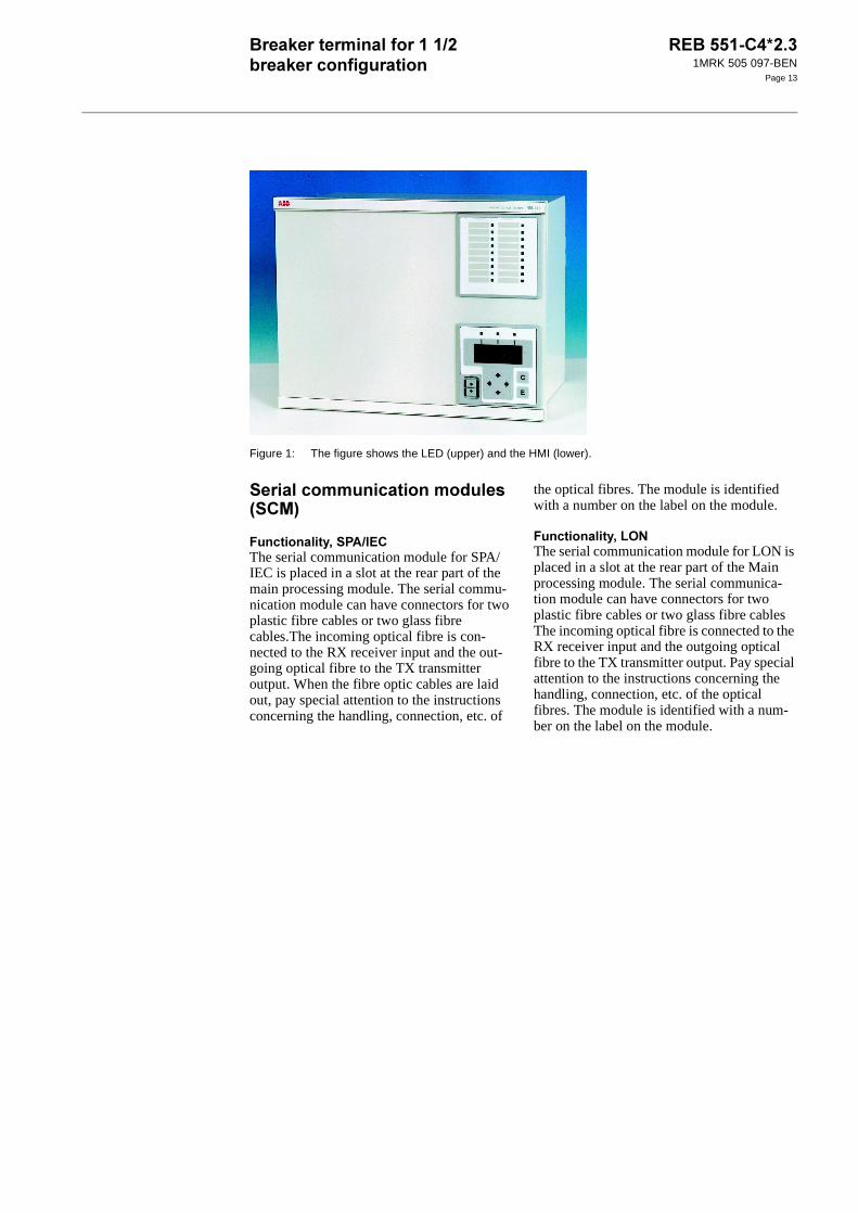
Figure 1: The figure shows the LED (upper) and the HMI (lower).
+1'+)*
%:+ !(The serial communication module for SPA/IEC is placed in a slot at the rear part of the main processing module. The serial commu-nication module can have connectors for two plastic fibre cables or two glass fibre cables.The incoming optical fibre is con-nected to the RX receiver input and the out-going optical fibre to the TX transmitter output. When the fibre optic cables are laid out, pay special attention to the instructions concerning the handling, connection, etc. of
the optical fibres. The module is identified with a number on the label on the module.
%:3.2The serial communication module for LON is placed in a slot at the rear part of the Main processing module. The serial communica-tion module can have connectors for two plastic fibre cables or two glass fibre cables The incoming optical fibre is connected to the RX receiver input and the outgoing optical fibre to the TX transmitter output. Pay special attention to the instructions concerning the handling, connection, etc. of the optical fibres. The module is identified with a num-ber on the label on the module.

1MRK 505 097-BEN
Page 14
-1/1 3%11
#
#:/&0
Figure 2: Case without rear cover
Figure 3: Case without rear cover with 19” rack mounting kit
A
B C
D
E
xx02000646.vsd
F
GH
J
K
xx02000647.vsd
@ ! # , - A B
6U, 1/2 x 19”
265.9
223.7 205.7
190.5
203.7 - -
6U, 3/4 x 19” 336 204.1 252.9 318 316 - 186.6 -
6U, 1/1 x 19” 448.3 430.3 428.3 465.1 482.6
The H and K dimensions are defined by the 19” rack mounting kit
(mm)

1MRK 505 097-BEN
Page 15
#:/&0
Figure 4: Case with rear cover Figure 5: Case with rear cover and 19” rack mounting kit
Figure 6: Case with rear cover
A
B CD
E
F
xx02000648.vsd
J
IH
G
K
xx02000649.vsd
xx02000650.vsd
@ ! # , - ( A B
6U, 1/2 x 19” 223.7 205.7 203.7 - -
6U, 3/4 x 19” 265.9 336 204.1 245.1 255.8 318 190.5 316 - 227.6 -
6U, 1/1 x 19” 448.3 430.3 428.3 465.1 482.6
The I and K dimensions are defined by the 19” rack mounting kit.
(mm)

1MRK 505 097-BEN
Page 16
5<<:
Flush mounting Semi-flush mounting
@
1'*
!C C
6U, 1/2 x 19” 210.1 254.3
6U, 3/4 x 19” 322.4 254.3
6U, 1/1 x 19” 434.7 254.3
C = 4-10 mm
D = 16.5 mm
E = 187.6 mm without rear protection cover, 228.6 mm with rear protection cover
F = 106.5 mm
G = 97.6 mm without rear protection cover, 138.6 mm with rear protection cover
A
B
C
D
E
xx02000665.vsd
F
G
xx02000666.vsd

1MRK 505 097-BEN
Page 17
5<<:1%1
Figure 7: Flush mounting of side by side cases
@ 1
! # ,
6U, 3/4 x 19” 326.4 259.3 352.8 190.5 34.4 13.2 ø 6.4
6U, 1/1 x 19” 438.7 259.3 465.1 190.5 34.4 13.2 ø 6.4
(mm)
B
A
C
G
D
E
F
xx02000651.vsd
xx02000652.vsd

1MRK 505 097-BEN
Page 18
#:/
Figure 8: Wall mounting
@'* ! #
6U, 1/2 x 19” 292 267.1
6U, 3/4 x 19” 404.3 379.4 272.8 390 247
6U, 1/1 x 19” 516 491.1
80
xx02000653.vsd
E
A
B
CD
Screws M6 orcorresponding
en02000654.vsd

1MRK 505 097-BEN
Page 19
$1 #/
Figure 9: Hardware structure of the 3/4 of full width 19” case
$&1 ,
#
$ ? 8
:
0?
The specified value of an influencing factor to which are referred the characteristics of the
equipment.
2?
The range of values of an influencing quantity (factor) whithin which, under specified condi-tions, the equipment meets the specified requirements.
."0?
The range of values of a given energizing quantity for which the equipment, under specified conditions, is able to perform its intended functions according to the specified requirements.
Material Steel sheet
Front plate Aluminium profile with cut-out for HMI and for 18 LED when included
Surface treatment Aluzink preplated steel
Finish Light beige (NCS 1704-Y15R)
Degree of protection Front side: IP40, optional IP54 with sealing strip. Rear side: IP20

1MRK 505 097-BEN
Page 20
$? D&
$? +)< <D
$;? $):@E:101
$>? $"1&1%
$=? !5%#""%0%1"
@ D&
6U, 3/4 x 19” ≤ 11 kg
6% 10 2
Auxiliary dc voltage EL = (48 - 250) V +/- 20%
6% 10 2
Current Ir = 1 or 5 A (0.2-30) × IrOperative range (0.004-100) x IrPermissive overload 4 × Ir cont.
100 × Ir for 1 s *)
Burden < 0.25 VA at I = 1 or 5 A
Ac voltage for the terminal Ur = 110 V **)
or
Ur = 220 V **)
100/110/115/120 V
200/220/230/240 V
Operative range (0.001-1.5) x Ur
Permissive overload 1.5 × Ur cont.
2.5 x Ur for 1 s
Burden < 0.2 VA at Ur
Frequency fr = 50/60 Hz +/-5%*) max. 350 A for 1 s when COMBITEST test switch is included.
**) The rated voltage of each individual voltage input U1 to U5 is Ur/√3
0 2 (
Ambient temperature
Operative range
+20 °C
-25 °C to +55°C
-5 °C to +55 °C 0.01%/°C
Relative humidity
Operative range
10%-90%
0%-95%
10%-90% -
Storage temperature -40 °C to +70 °C - -
#"1? D&
Ripple, in DC auxiliary voltage Max 12%
Interrupted auxiliary DC voltage
Without reset <50 ms
Correct function 0-∞ s
Restart time <120 s
1MRK 505 097-BEN
Page 21
$F? "%
$<? (
$? "
$? )&
$ ? 11
$? (0
$? $():$%&
$ $%"0 11
1 MHz burst disturbance 2.5 kV IEC 60255-22-1, Class III
Electrostatic discharge 8 kV IEC 60255-22-2, Class III
Fast transient disturbance 4 kV IEC 60255-22-4, Class IV
Radiated electromagnetic field distur-bance
10 V/m, 25-1000 MHz
IEC 60255-22-3, Class III IEEE/ANSI C37.90.2
$ $%"0 11
Dielectric test 2.0 kVAC, 1 min. IEC 60255-5
Impulse voltage test 5 kV, 1.2/50 µs, 0.5 J
Insulation resistance >100 MΩ at 500 VDC
$ !1
Immunity EN 50082-2
Emissivity EN 50081-2
Low voltage directive EN 50178
$ $%"0 11
Vibration Class I IEC 60255-21-1
Shock and bump Class I IEC 60255-21-2
Seismic Class I IEC 60255-21-3
Built-in calender With leap years through 2098
# 4
Recording manner Continuous, event con-
trolled
List size 40 events, first in-first out
!%
Time tagging resolution 1 ms
Time tagging error with synchronisation at least once/60 s
+/- 1.5 ms
Drift of clock without synchronisation +/- 3 ms/min

1MRK 505 097-BEN
Page 22
$;?
$>? !0
$=? "
4
Protocol SPA
Communication speed for the cable 0.3-115 Kbaud
Slave number 1 to 899
Remote change of active group allowed Yes
Remote change of settings allowed Yes
8"1 !0%
6 ms AND 30 gates
OR 60 gates
INV 20 inverters
TM 10 timers
TP 10 pulse timers
SM 5 flip-flops
GT 5 gates
TS 5 timers
200 ms TL 10 timers
TQ 10 pulse timers
SR 5 flip-flops
XOR 39 gates
+ !%
Operate current (one mea-suring element per phase)
5-200% of I1b in steps of 1% +/-2.5% of Ir at I ≤ Ir+/-2.5% of I at I > Ir
Retrip time delay t1 0.000-60.000 s in steps of 1 ms
+/-0.5% +/-10 ms
Back-up trip time delay t2 0.000-60.000 s in steps of 1
ms
+/-0.5% +/-10 ms
4
Trip operate time Max 18 ms
Reset time Max 10 ms

1MRK 505 097-BEN
Page 23
/%"0
$F? 30&
$<? .01"0
$? #3##11
+1%%"0
$? "0
$ ? 8+"0
$? !!
+ !%
Operate voltage, U< 10-100% of U1b in steps of
1%
+/-2.5% of Ur
+ !%
Operate current I> 20-300% of I1b in steps of 1% +/-2.5% of Ir at I≤Ir+/-2.5% of I at I>Ir
Time delay 0.0-90000.0 s
Step: 0.1
+/-0.5% +/- 10 ms
+ !%
Automatic check of dead line condition
Operate phase current (5-100) % of I1b in steps of 1%
+/- 2.5 % of Ir
Operate phase voltage (10-100) % of U1b in steps of 1%
+/- 2.5 % of Ur
+ !%
Operate current I> 5-100% of I1b in steps of 1% +/-2.5% of Ir
+ !%
Zero-sequence
quantities:
Operate voltage
3U0
(10-50)% of U1b in steps of
1%
+/- 2.5 % of Ur
Operate current 3I0
(10-50)% of I1b in steps of 1% +/- 2.5 % of Ir
+ !%
Automatic reclosing open time:
shot 1 - t1 1ph 0.000-60.000 s in steps of 1 ms
+/- 0.5% +/- 10 ms
shot 1 - t1 2ph 0.000-60.000 s in steps of
1 ms
+/- 0.5% +/- 10 ms
shot 1 - t1 3ph 0.000-60.000 s in steps of 1 ms
+/- 0.5% +/- 10 ms

1MRK 505 097-BEN
Page 24
$? !
shot 2 - t2 3ph 0-90000.0 s in steps of 0.1
s
+/- 0.5% +/- 10 ms
shot 3 - t3 3ph 0-90000.0 s in steps of 0.1 s
+/- 0.5% +/- 10 ms
shot 4 - t4 3ph 0-90000.0 s in steps of 0.1
s
+/- 0.5% +/- 10 ms
Maximum wait time for OK to close from synchronizing function tSync
0-90000.0 s in steps of 0.1 s
+/- 0.5% +/- 10 ms
Duration of close pulse to circuit breaker tPulse
0.000-60.000 s in steps of 1 ms
+/- 0.5% +/- 10 ms
Duration of reclaim time tReclaim 0-90000.0 s in steps of 0.1
s
+/- 0.5% +/- 10 ms
Inhibit reclosing reset time tInhibit 0.000-60.000 s in steps of 1 ms
+/- 0.5% +/- 10 ms
Maximum trip pulse duration tTrip (longer trip pulse durations will either
extend the dead time or interrupt the reclosing sequence)
0.000-60.000 s in steps of 1 ms
+/- 0.5% +/- 10 ms
Maximum wait time for release from Master tWaitForMaster
0-9000.0 s in steps of 0.1 s +/- 0.5% +/- 10 ms
Wait time following close command
before continuing with further reclosing attempts without new start signal if cir-cuit breaker does not close tAutoWait
0.000-60.000 s in steps of
1 ms
+/- 0.5% +/- 10 ms
Time delay before indicating reclosing
unsuccessful tUnsuc
0-9000.0 s in steps of 0.1 s +/- 0.5% +/- 10 ms
Time CB must be closed before AR becomes ready for a reclosing cycle tCBClosed
0.000-60.000 s in steps of 1 ms
+/- 0.5% +/- 10 ms
4
Reclosing shots 1-4
Programs Three pole trip: 1
Single, two and three pole trip: 6
Number of instances Up to six depending on terminal type (different terminal types support dif-ferent CB arrangements and numbers
of bays)
Breaker closed before start 5 s
+ !%

1MRK 505 097-BEN
Page 25
3
$;? $$"
$>? # 11:11
$=? +'+ !*
$F? +'3.2*
$ <? +'(;<=><< *
)
$ ? #""
4 !%
Setting for the minimum trip
pulse length, tTripMin
0.000 - 60.000 s in steps of
0.001 s
+/-0.5% +/-10 ms
+ !%
Auxiliary-contact-based function - time delay
(0.000-60.000) s in steps of 1 ms
+/- 0.5% +/- 10 ms
Operate current 10% of I1b +/- 2.5 % of IrTime delay (0.000-60.000) s in steps of 1
ms+/- 0.5 % +/- 10 ms
4
Protocol SPA
Communication speed 300, 1200, 2400, 4800, 9600, 19200 or 38400 bit/s
Slave number 1 to 899
Remote change of active group allowed yes/no
Remote change of settings allowed yes/no
Connectors and optical fibres glass or plastic
4
Protocol LON
Communication speed 1.25 Mbit/s
Connectors and optical fibres glass or plastic
4
Protocol IEC 60870-5-103
Communication speed 9600, 19200 bit/s
Connectors and optical fibres glass or plastic
# +
Pre-fault time 50-300 ms in steps of 10 ms
Post-fault time 100-5000 ms in steps of 100 ms
Limit time 500-6000 ms in steps of 100 ms
Number of recorded disturbances Max. 10
1MRK 505 097-BEN
Page 26
$ ? 01
$ ? )0'!*
$ ? )()!
4
Event buffering capacity Max. number of events/distur-bance report
150
Max. number of disturbance
reports
10
2 !%
Frequency (0.95 - 1.05) x fr +/- 0.2 Hz
Voltage (RMS) Ph-Ph (0.1 - 1.5) x Ur +/- 2.5% of Ur, at U≤ Ur
+/- 2.5% of U, at U> Ur
Current (RMS) (0.2 - 4) x Ir +/- 2.5% of Ir, at I≤ Ir
+/- 2.5% of I, at I> IrActive power*) at |cos ϕ| ≥ 0.9 +/- 5%
Reactive power*) at |cos ϕ| ≤ 0.8 +/- 7.5%
*) Measured at Ur and 20% of Ir
+ !%
mA measuring function +/- 5, +/- 10, +/- 20 mA 0-5, 0-10, 0-20, 4-20 mA
+/- 0.1 % of set value +/-0.005
mAMax current of transducer to input
(-25.00 to +25.00) mA in steps of 0.01
Min current of transducer to
input
(-25.00 to +25.00) mA in steps
of 0.01
High alarm level for input (-25.00 to +25.00) mA in steps of 0.01
High warning level for input (-25.00 to +25.00) mA in steps of 0.01
Low warning level for input (-25.00 to +25.00) mA in steps
of 0.01
Low alarm level for input (-25.00 to +25.00) mA in steps of 0.01
Alarm hysteresis for input (0-20) mA in steps of 1
Amplitude dead band for input
(0-20) mA in steps of 1
Integrating dead band for
input
(0.00-1000.00) mA in steps of
0.01

1MRK 505 097-BEN
Page 27
-1/1
$ ? %"
$ ;? %"
$ >? +)+0
(" 3 3= 3< 3<
Binary inputs BIM: 16, IOM: 8, PSM: 4
Debounce frequency 5 Hz (BIM), 1 Hz (IOM)
Oscillating signal discrimi-
nator.*
Blocking and release settable between 1-40 Hz
Binary input voltage RL 24/30 VDC
+/-20%
48/60 VDC
+/-20%
110/125 VDC
+/-20%
220/250 VDC
+/-20%
Power consumption (max.) 0.05 W/input 0.1 W/input 0.2 W/input 0.4 W/input
*) Only available for BIM
E% $"1+%
%
Binary outputs BOM: 24, IOM: 10,
PSM: 4
IOM: 2
Max system voltage 250 V AC, DC 250 V AC, DC
Test voltage across open contact, 1 min 1000 V rms 800 V DC
Current carrying capacity
Continuous 8 A 8 A
1 s 10 A 10 A
Making capacity at inductive load with L/
R>10 ms
0.2 s 30 A 0.4 A
1.0 s 10 A 0.4 A
Breaking capacity for AC, cos ϕ>0.4 250 V/8.0 A 250 V/8.0 A
Breaking capacity for DC with L/R<40ms 48 V/1 A 48 V/1 A
110 V/0.4 A 110 V/0.4 A
220 V/0.2 A 220 V/0.2 A
250 V/0.15 A 250 V/0.15 A
Maximum capacitive load - 10 nF
4
Protocol SPA
Communication speed for the terminals 300, 1200, 2400, 4800, 9600 Kbaud
Slave number 1 to 899
Change of active group allowed Yes
Change of settings allowed Yes

1MRK 505 097-BEN
Page 28
$ =? E+ !(
$ F? 3.2E3.2
,
Cable connector ST connector HFBR, Snap-in connector
Fibre diameter 62.5/125 µm
50/125 µm
1 mm
Max. cable length 500 m 30 m
,
Cable connector ST-connector HFBR, Snap-in connector
Fibre diameter 62.5/125 µm
50/125 µm
1 mm
Max. cable length 1000 m 30 m

1MRK 505 097-BEN
Page 29
.1 ,1Carefully read and follow the set of rules to ensure problem-free order management. Be aware that certain functions can only be ordered in combination with other functions and that some functions require specific hardware selections.
&1/1
1%
)#
%(."
)"
/%"0
+1%%"0
+%
Basic REx 5xx platform and common functions housed in 3/4 sized 19” casing
Operator’s manual (English)
Installation and commissioning manual (English)
Technical reference manual (English)
Application manual (English)
Binary I/O resided on power supply module
Four binary I/O modules
A/D module
Transformer module
Pole discordance protection
Current based
Contact based
Breaker failure protection
Dead line detection
Loss of voltage check
Overload supervision
Current circuit supervision
Fuse failure supervision
Zero sequence
Synchrocheck
For 1 1/2 breaker arrangement, including energizing check
Automatic reclosing function
For single CB, one and/or three phase reclosing

1MRK 505 097-BEN
Page 30
3
)
1"
)"Add measuring capabilities by selecting input energizing options from the following tables.
Trip logic
Single and/or three pole trip
Event recorder
Trip value recorder
Analog AC monitor software
Analog DC monitor software (Requires optional mA-transducer module, MIM)
REB 551-C4 Quantity: 1MRK 004 498-DA
!
Engergizing quantities for binary inputs on
power supply module
24/30 V 1MRK 002 238-AA
48/60 V 1MRK 002 238-BA
110/125 V 1MRK 002 238-CA
220/250 V 1MRK 002 238-DA
"# $%#&'()''*#%)+,-./0!
1&*#.
Energizing quantities for binary I/O modules
Module 1 Module 2 Module 3 Module 4
24/30 V 1MRK 000 173-GB
48/60 V 1MRK 000 173-AC
110/125 V 1MRK 000 173-BC
220/250 V 1MRK 000 173-CC
!21)) &1
1))#%)1*"3!
Rated measuring input energizing quantities 1 A, 110 V 1MRK 000 157-MB
1 A, 220 V 1MRK 000 157-VB
5 A, 110 V 1MRK 000 157-NB
5 A, 220 V 1MRK 000 157-WB

1MRK 505 097-BEN
Page 31
."
!11-)(
-1/
++1+)+"
$/&
0
)
)'))3
Second language beside English German 1MRK 001 459-AA
Russian 1MRK 001 459-BA
French 1MRK 001 459-CA
Spanish 1MRK 001 459-DA
Italian 1MRK 001 459-EA
Customer specific language Contact your local ABB representative for availability
SMS communication, only one alternative can be selected
SPA/IEC 60870-5-103 interface Plastic fibers 1MRK 000 168-FA
Glass fibers 1MRK 000 168-DA
SCS communication, only one alternative can be selected
LON interface Plastic fibers 1MRK 000 168-EA
Glass fibers 1MRK 000 168-DA
Test switch module RTXP 24 mounted side-by-side to the terminal in RHGS case
1MRK 000 371-CA
With internal earthing RK 926 215-BB
With external earthing RK 926 215-BC
On/off switch for the DC-supply RK 795 017-AA
Cover for rear area including fixing
screws and assembly instruction 6U, 3/4 x 19” 1MRK 000 020-AB
19” rack mounting kit 1MRK 000 020-BR
Wall mounting kit 1MRK 000 020-DA
Flush mounting kit 1MRK 000 020-Y
Semiflush mounting kit 1MRK 000 020-BS
Additional mounting seal for IP54 protection of flush and
semiflush mounted terminals
1MKC 980 001-2
Side-by-side mounting kit 1MRK 000 020-Z

1MRK 505 097-BEN
Page 32
!
B%/&
)
1
11
)
Key switch for setting lockout Quantity: 1MRK 000 611-A
Front connection cable for PC (Opto/9-pole D-sub)
Quantity: 1MKC 950 001-2
(&'4)*%&1*%2)#**))$
*#''*)()##1&*!
'1&*31"4)5)#
CD with all manuals Quantity: 1MRK 002 241-AA
'1&*31'#*)5)#
Operator’s manual Quantity: 1MRK 505 025-UEN
Technical reference manual Quantity: 1MRK 505 026-UEN
Installation and commissioning manual Quantity: 1MRK 505 027-UEN
Application manual Quantity: 1MRK 505 091-UEN
For our reference and statistics we would be pleased to be provided with the following applica-
tion data:
Country: End user:
Station name: Voltage level: kV
$&00/&
Accessories for REx 5xx*2.3 1MRK 514 009-BEN
CAP 540*1.2 1MRK 511 112-BEN
!!$&% 1!
Substation Automation
SE-721 59 Västerås
Sweden
Telephone: +46 (0) 21 34 20 00
Facsimile: +46 (0) 21 14 69 18
Internet: www.abb.com/substationautomation