
===!"§ Deutsche Telekom Laboratories Target Acquisition with Camera Phones when used as Magic...
23
===!"§ Deutsche Telekom Laboratories Target Acquisition with Camera Phones when used as Magic Lenses CHI 2008, Florence, Italy, April 9, 2008 Michael Rohs Deutsche Telekom Laboratories Technische Universität Berlin Antti Oulasvirta Helsinki Institute for Information Technology HIIT
-
Upload
james-fowler -
Category
Documents
-
view
214 -
download
0
Transcript of ===!"§ Deutsche Telekom Laboratories Target Acquisition with Camera Phones when used as Magic...
===!"§Deutsche Telekom Laboratories
Target Acquisition with Camera Phoneswhen used as Magic LensesCHI 2008, Florence, Italy, April 9, 2008
Michael Rohs
Deutsche Telekom LaboratoriesTechnische Universität Berlin
Antti Oulasvirta
Helsinki Institute for Information Technology HIIT
Page 2===!"§
Deutsche Telekom Laboratories
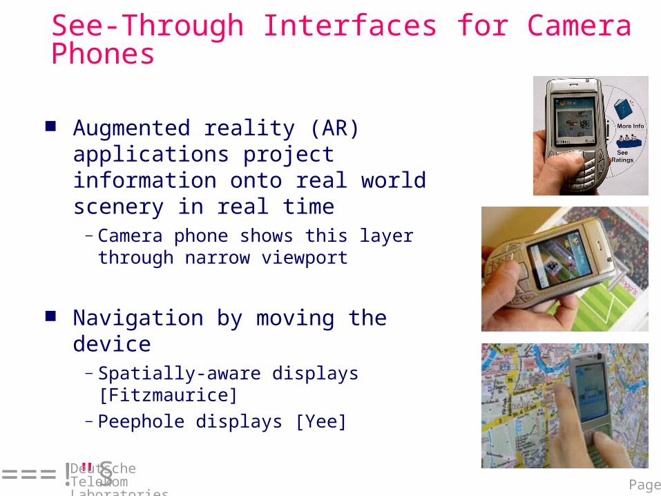
See-Through Interfaces for Camera Phones
Augmented reality (AR) applications project information onto real world scenery in real time
—Camera phone shows this layer through narrow viewport
Navigation by moving the device—Spatially-aware displays [Fitzmaurice]—Peephole displays [Yee]

Page 3===!"§
Deutsche Telekom Laboratories
Magic Lens for Paper Maps
Page 4===!"§
Deutsche Telekom Laboratories
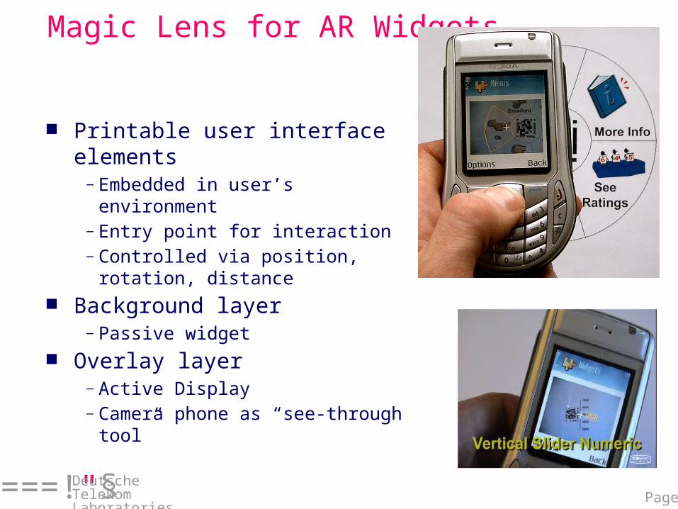
Magic Lens for AR Widgets
Printable user interface elements
—Embedded in user’s environment
—Entry point for interaction—Controlled via position, rotation,
distance Background layer
—Passive widget Overlay layer
—Active Display—Camera phone as “see-through
tool”
Page 5===!"§
Deutsche Telekom Laboratories
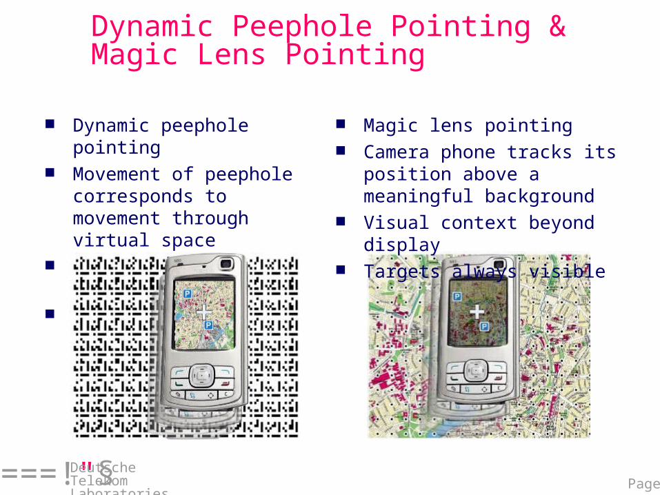
Dynamic Peephole Pointing & Magic Lens Pointing
Dynamic peephole pointing
Movement of peephole corresponds to movement through virtual space
No visual context beyond display
Targets dynamically revealed
Magic lens pointing Camera phone tracks its
position above a meaningful background
Visual context beyond display
Targets always visible
Page 6===!"§
Deutsche Telekom Laboratories
Target Acquisition with Camera Phones
Two distinct categories of interfaces—Dynamic peephole: Objects of interest only in virtual—Magic lens: Objects of interest on the physical surface
Analyzing target acquisition with camera phones—Performance—Modeling
Page 7===!"§
Deutsche Telekom Laboratories
Overview
Analysis of the Pointing Tasks Two-Component Model of Magic Lens Pointing Experiment 1: Dynamic Peephole Pointing Experiment 2: Magic Lens Pointing
Page 8===!"§
Deutsche Telekom Laboratories
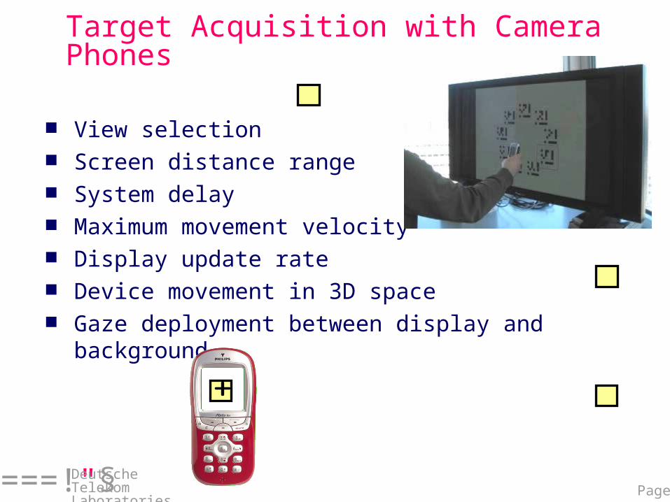
Target Acquisition with Camera Phones
View selection Screen distance range System delay Maximum movement velocity Display update rate Device movement in 3D space Gaze deployment between display and
background
Page 9===!"§
Deutsche Telekom Laboratories
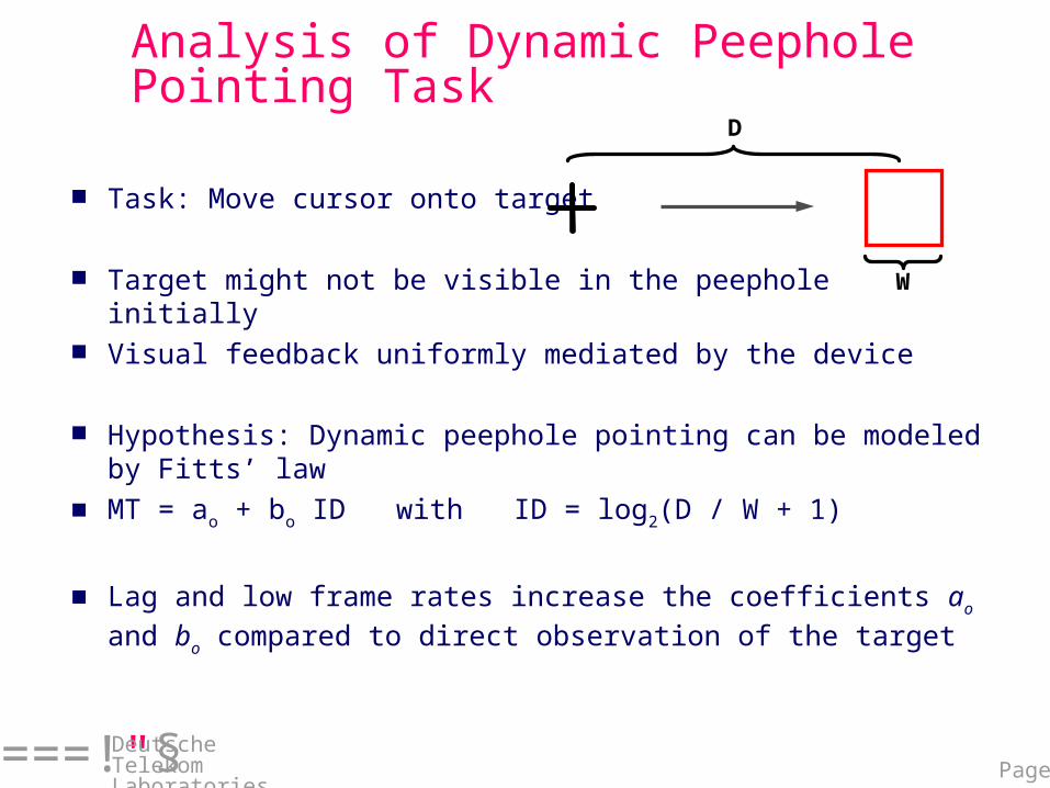
Analysis of Dynamic Peephole Pointing Task
Task: Move cursor onto target
Target might not be visible in the peephole initially Visual feedback uniformly mediated by the device
Hypothesis: Dynamic peephole pointing can be modeled by Fitts’ law
MT = ao + bo ID with ID = log2(D / W + 1)
Lag and low frame rates increase the coefficients ao and bo compared to direct observation of the target
W
D
Page 10===!"§
Deutsche Telekom Laboratories
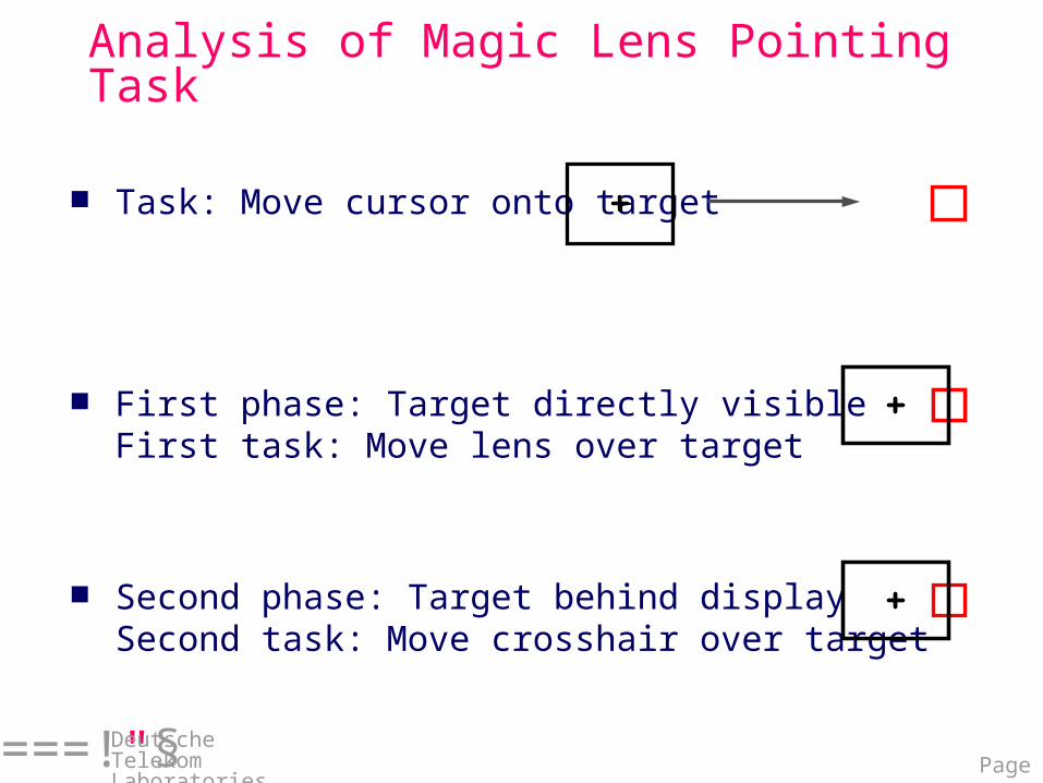
Analysis of Magic Lens Pointing Task
Task: Move cursor onto target
First phase: Target directly visibleFirst task: Move lens over target
Second phase: Target behind displaySecond task: Move crosshair over target
T
Page 11===!"§
Deutsche Telekom Laboratories
Analysis of Magic Lens Pointing Task
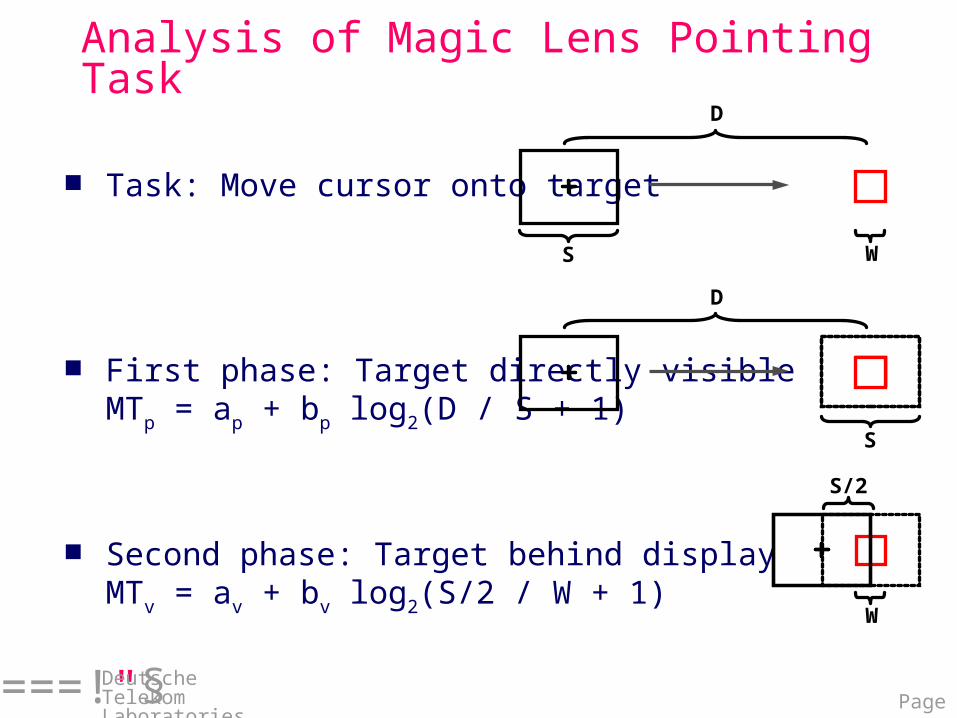
Task: Move cursor onto target
First phase: Target directly visibleMTp = ap + bp log2(D / S + 1)
Second phase: Target behind displayMTv = av + bv log2(S/2 / W + 1)
S W
W
S/2
D
T
S
D
Page 12===!"§
Deutsche Telekom Laboratories
Magic Lens Pointing Model
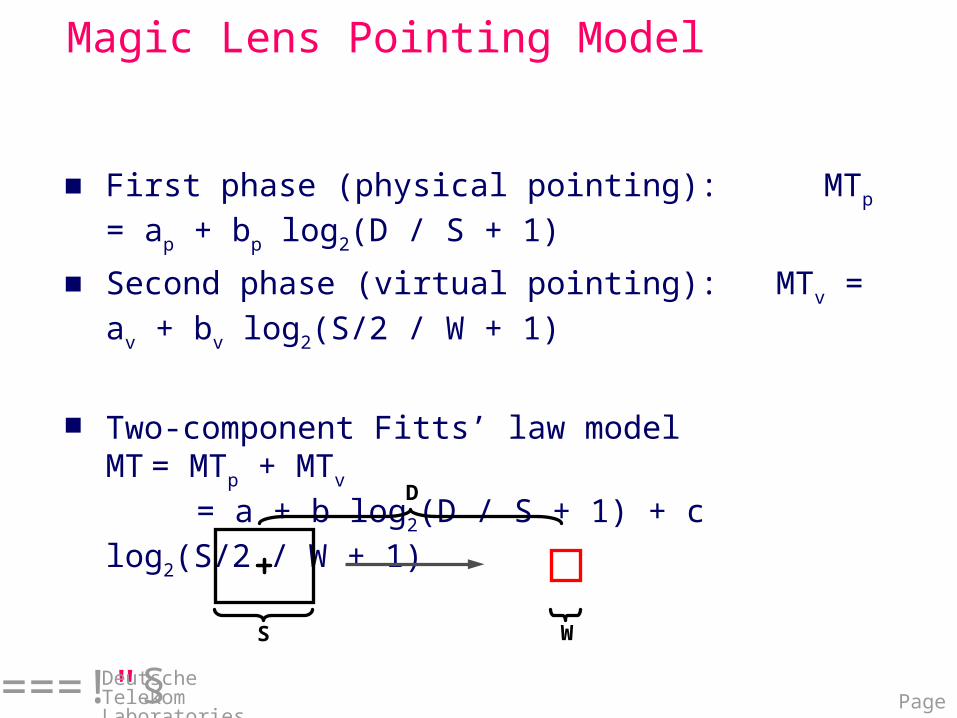
First phase (physical pointing): MTp = ap + bp log2(D / S + 1)
Second phase (virtual pointing): MTv = av + bv log2(S/2 / W + 1)
Two-component Fitts’ law modelMT = MTp + MTv
= a + b log2(D / S + 1) + c log2(S/2 / W + 1)
S W
D
Page 13===!"§
Deutsche Telekom Laboratories
physical pointing
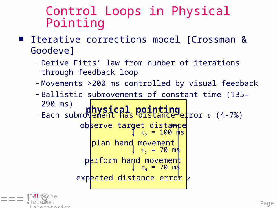
Control Loops in Physical Pointing
Iterative corrections model [Crossman & Goodeve]
—Derive Fitts’ law from number of iterations through feedback loop
—Movements >200 ms controlled by visual feedback—Ballistic submovements of constant time (135-290 ms)—Each submovement has distance error (4-7%)
observe target distance P = 100 ms
plan hand movement C = 70 ms
perform hand movement M = 70 ms
expected distance error
Page 14===!"§
Deutsche Telekom Laboratories
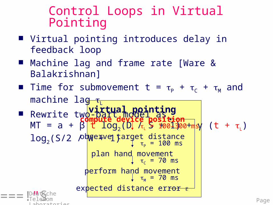
Control Loops in Virtual Pointing
Virtual pointing introduces delay in feedback loop
Machine lag and frame rate [Ware & Balakrishnan]
Time for submovement t = P + C + M and machine lag L
Rewrite two-part model asMT = a + β t log2(D / S + 1) + γ (t + L) log2(S/2 / W + 1) observe target distance
P = 100 ms
plan hand movement
perform hand movement
expected distance error
C = 70 ms
M = 70 ms
virtual pointingcompute device position
L = 100–300 ms
Page 15===!"§
Deutsche Telekom Laboratories
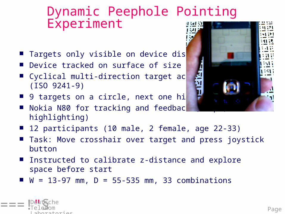
Dynamic Peephole Pointing Experiment
Targets only visible on device display Device tracked on surface of size A0 Cyclical multi-direction target acquisition
(ISO 9241-9) 9 targets on a circle, next one highlighted Nokia N80 for tracking and feedback (beeps, highlighting) 12 participants (10 male, 2 female, age 22-33) Task: Move crosshair over target and press joystick
button Instructed to calibrate z-distance and explore space
before start W = 13-97 mm, D = 55-535 mm, 33 combinations
Page 16===!"§
Deutsche Telekom Laboratories
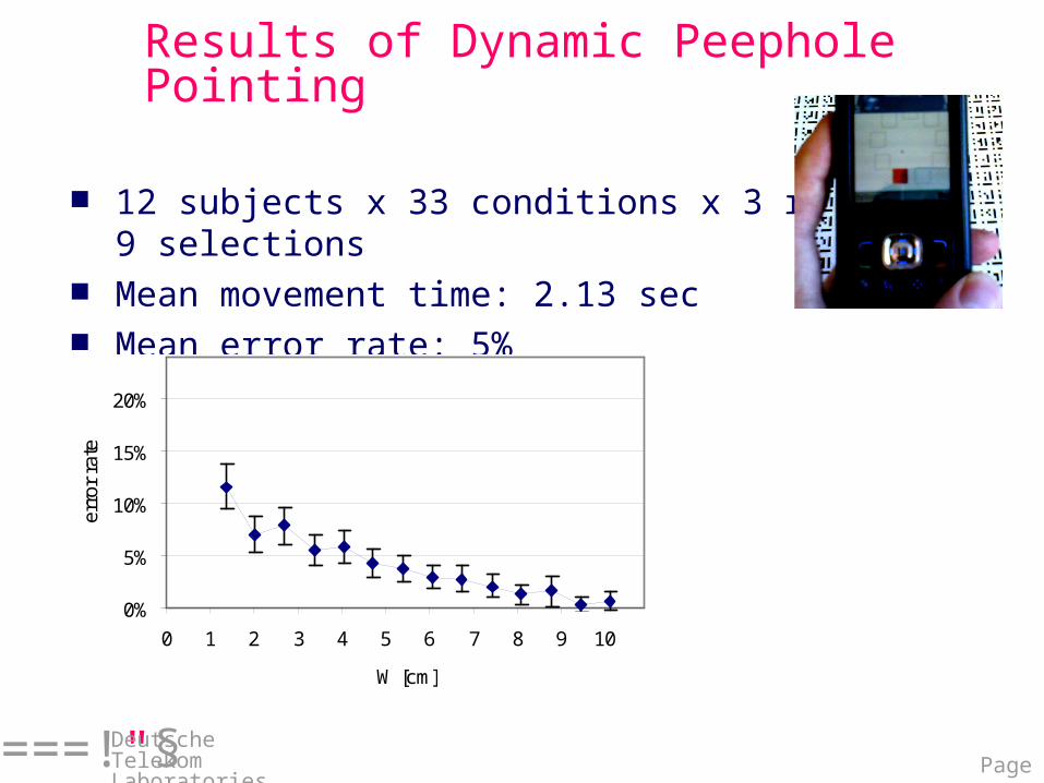
Results of Dynamic Peephole Pointing
12 subjects x 33 conditions x 3 rounds x 9 selections
Mean movement time: 2.13 sec Mean error rate: 5%
0%
5%
10%
15%
20%
0 1 2 3 4 5 6 7 8 9 10
W [cm]
erro
r ra
te
Page 17===!"§
Deutsche Telekom Laboratories
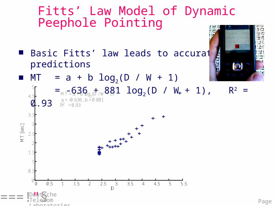
Fitts’ Law Model of Dynamic Peephole Pointing
Basic Fitts’ law leads to accurate predictions MT = a + b log2(D / W + 1)
= -636 + 881 log2(D / W + 1), R2 = 0.93
0 0.5 1 1.5 2 2.5 3 3.5 4 4.5 5 5.5ID
MT
[se
c]
MT = a + b log2 (D / W + 1)
a = 0.636, b = 0.881R2 = 0.93
0 0.5 1 1.5 2 2.5 3 3.5 4 4.5 5 5.50
0.5
1
1.5
2
2.5
3
3.5
4
4.5
5
ID
MT
[se
c]
-
Page 18===!"§
Deutsche Telekom Laboratories
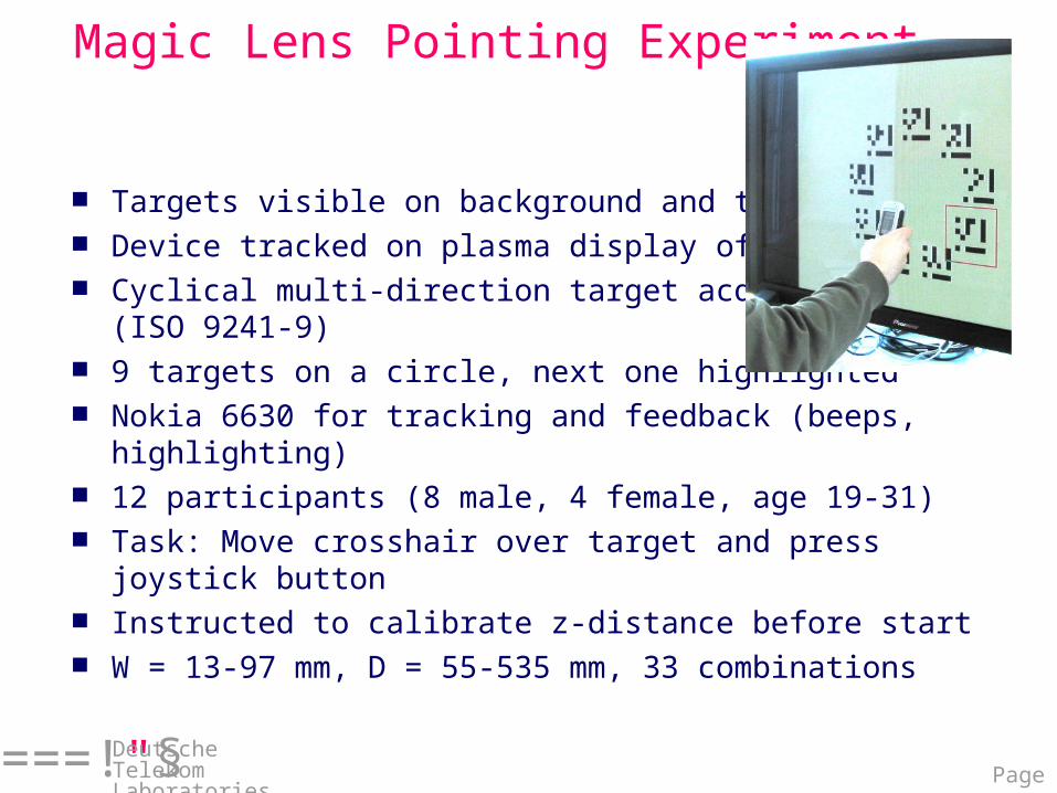
Magic Lens Pointing Experiment
Targets visible on background and through lens Device tracked on plasma display of size A0 Cyclical multi-direction target acquisition
(ISO 9241-9) 9 targets on a circle, next one highlighted Nokia 6630 for tracking and feedback (beeps,
highlighting) 12 participants (8 male, 4 female, age 19-31) Task: Move crosshair over target and press joystick
button Instructed to calibrate z-distance before start W = 13-97 mm, D = 55-535 mm, 33 combinations
Page 19===!"§
Deutsche Telekom Laboratories
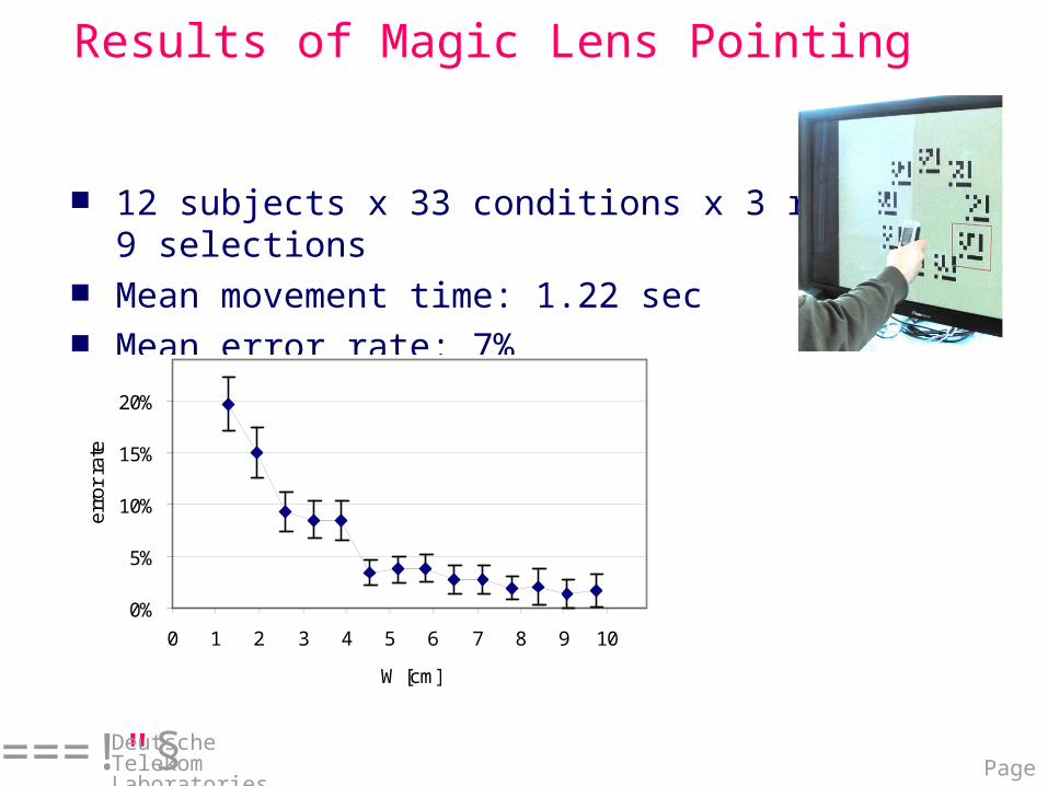
Results of Magic Lens Pointing
12 subjects x 33 conditions x 3 rounds x 9 selections
Mean movement time: 1.22 sec Mean error rate: 7%
0%
5%
10%
15%
20%
0 1 2 3 4 5 6 7 8 9 10
W [cm]
erro
r ra
te
Page 20===!"§
Deutsche Telekom Laboratories
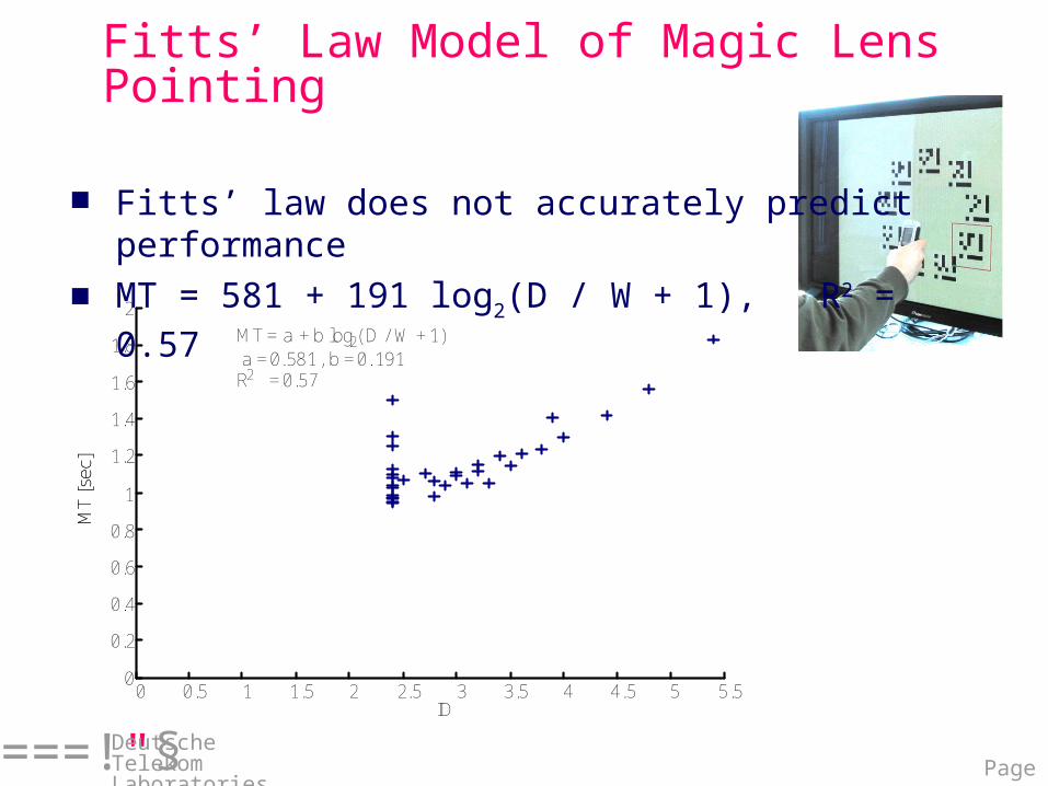
Fitts’ Law Model of Magic Lens Pointing
Fitts’ law does not accurately predict performance
MT = 581 + 191 log2(D / W + 1), R2 = 0.57
0 0.5 1 1.5 2 2.5 3 3.5 4 4.5 5 5.50
0.2
0.4
0.6
0.8
1
1.2
1.4
1.6
1.8
2
ID
MT
[sec
]
MT = a + b log2 ( D / W + 1)a = 0.581, b = 0. 191R2 = 0.57
MT
[sec
]
Page 21===!"§
Deutsche Telekom Laboratories
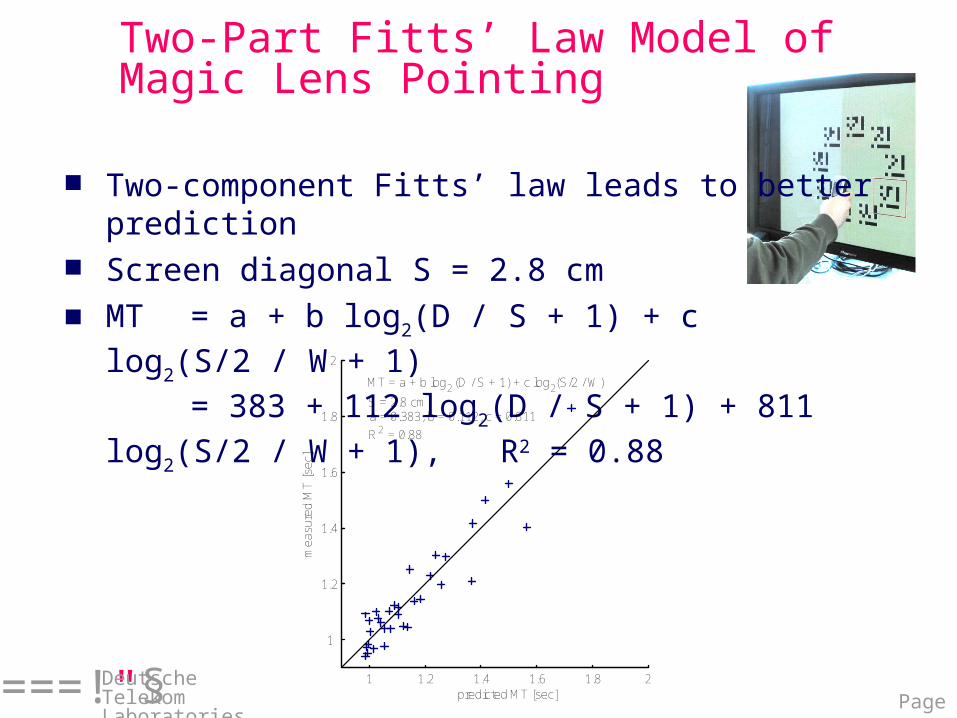
Two-Part Fitts’ Law Model of Magic Lens Pointing
Two-component Fitts’ law leads to better prediction
Screen diagonal S = 2.8 cm MT = a + b log2(D / S + 1) + c log2(S/2 / W +
1)= 383 + 112 log2(D / S + 1) + 811
log2(S/2 / W + 1), R2 = 0.88
1 1.2 1.4 1.6 1.8 2
1
1.2
1.4
1.6
1.8
2
predicted MT [sec]
mea
sure
dM
T [s
ec]
MT = a + b log2 (D / S + 1) + c log2(S/2 / W)
S = 2.8 cma = 0.383, b = 0.112, c = 0.811
R2 = 0.88
Page 22===!"§
Deutsche Telekom Laboratories
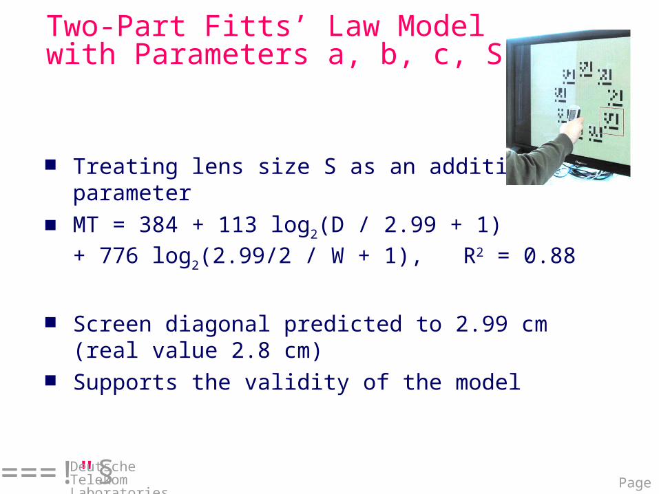
Two-Part Fitts’ Law Model with Parameters a, b, c, S
Treating lens size S as an additional parameter MT = 384 + 113 log2(D / 2.99 + 1)
+ 776 log2(2.99/2 / W + 1), R2 = 0.88
Screen diagonal predicted to 2.99 cm (real value 2.8 cm)
Supports the validity of the model
Page 23===!"§
Deutsche Telekom Laboratories
Conclusion
Analyzed target acquisition with camera phones as—Dynamic peephole displays—Magic lenses
Dynamic peephole pointing can be modeled with Fitts’ law—Interaction uniformly mediated by the device
Magic lens pointing not adequately explainable by Fitts’ law
—Initial physical pointing phase—Second virtual pointing phase
Developed two-part Fitts’ law model for magic lens pointing
—MT = a + b log2(D / S + 1) + c log2(S/2 / W + 1)
Numerous application ideas for magic lens interfaces