
======= C100 Cryomodule Supply/Return header …tnweb.jlab.org/tn/2007/07-051.pdfJLAB-TN-07-051...
21
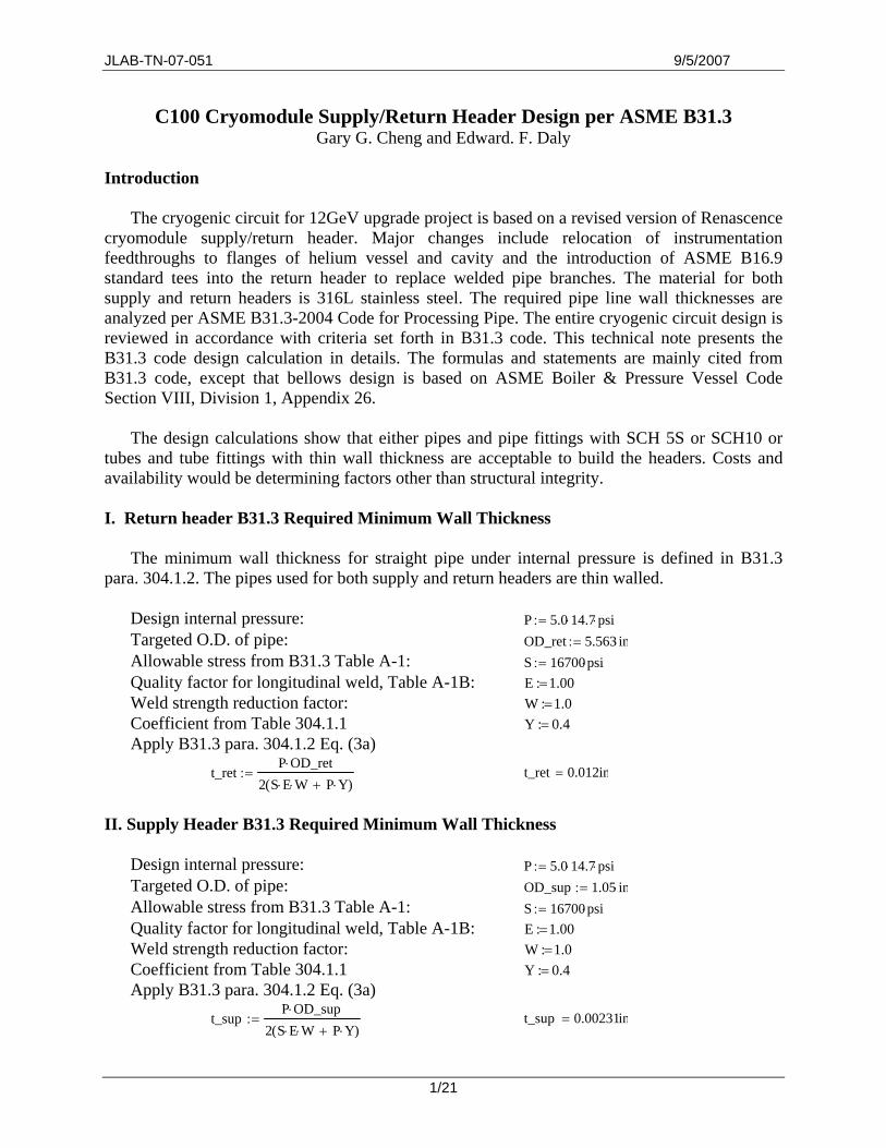
JLAB-TN-07-051 9/5/2007 C100 Cryomodule Supply/Return Header Design per ASME B31.3 Gary G. Cheng and Edward. F. Daly Introduction The cryogenic circuit for 12GeV upgrade project is based on a revised version of Renascence cryomodule supply/return header. Major changes include relocation of instrumentation feedthroughs to flanges of helium vessel and cavity and the introduction of ASME B16.9 standard tees into the return header to replace welded pipe branches. The material for both supply and return headers is 316L stainless steel. The required pipe line wall thicknesses are analyzed per ASME B31.3-2004 Code for Processing Pipe. The entire cryogenic circuit design is reviewed in accordance with criteria set forth in B31.3 code. This technical note presents the B31.3 code design calculation in details. The formulas and statements are mainly cited from B31.3 code, except that bellows design is based on ASME Boiler & Pressure Vessel Code Section VIII, Division 1, Appendix 26. The design calculations show that either pipes and pipe fittings with SCH 5S or SCH10 or tubes and tube fittings with thin wall thickness are acceptable to build the headers. Costs and availability would be determining factors other than structural integrity. I. Return header B31.3 Required Minimum Wall Thickness The minimum wall thickness for straight pipe under internal pressure is defined in B31.3 para. 304.1.2. The pipes used for both supply and return headers are thin walled. Design internal pressure: P 5.0 14.7 ⋅ psi ⋅ := Targeted O.D. of pipe: OD_ret 5.563 in ⋅ := Allowable stress from B31.3 Table A-1: S 16700 psi ⋅ := Quality factor for longitudinal weld, Table A-1B: 1.00 : E = Weld strength reduction factor: 1.0 : W = Coefficient from Table 304.1.1 0.4 : Y = Apply B31.3 para. 304.1.2 Eq. (3a) t_ret P OD_ret ⋅ 2SE ⋅ W ⋅ PY ⋅ + ( ) := t_ret 0.012in = II. Supply Header B31.3 Required Minimum Wall Thickness Design internal pressure: P 5.0 14.7 ⋅ psi ⋅ := Targeted O.D. of pipe: OD_sup 1.05 in ⋅ := Allowable stress from B31.3 Table A-1: S 16700 psi ⋅ := Quality factor for longitudinal weld, Table A-1B: 1.00 : E = Weld strength reduction factor: 1.0 : W = Coefficient from Table 304.1.1 0.4 : Y = Apply B31.3 para. 304.1.2 Eq. (3a) t_sup P OD_sup ⋅ 2SE ⋅ W ⋅ PY ⋅ + ( ) := t_sup 0.00231in = 1/21
Transcript of ======= C100 Cryomodule Supply/Return header …tnweb.jlab.org/tn/2007/07-051.pdfJLAB-TN-07-051...
JLAB-TN-07-051 9/5/2007
C100 Cryomodule Supply/Return Header Design per ASME B31.3 Gary G. Cheng and Edward. F. Daly
Introduction
The cryogenic circuit for 12GeV upgrade project is based on a revised version of Renascence
cryomodule supply/return header. Major changes include relocation of instrumentation feedthroughs to flanges of helium vessel and cavity and the introduction of ASME B16.9 standard tees into the return header to replace welded pipe branches. The material for both supply and return headers is 316L stainless steel. The required pipe line wall thicknesses are analyzed per ASME B31.3-2004 Code for Processing Pipe. The entire cryogenic circuit design is reviewed in accordance with criteria set forth in B31.3 code. This technical note presents the B31.3 code design calculation in details. The formulas and statements are mainly cited from B31.3 code, except that bellows design is based on ASME Boiler & Pressure Vessel Code Section VIII, Division 1, Appendix 26.
The design calculations show that either pipes and pipe fittings with SCH 5S or SCH10 or
tubes and tube fittings with thin wall thickness are acceptable to build the headers. Costs and availability would be determining factors other than structural integrity. I. Return header B31.3 Required Minimum Wall Thickness
The minimum wall thickness for straight pipe under internal pressure is defined in B31.3
para. 304.1.2. The pipes used for both supply and return headers are thin walled. Design internal pressure: P 5.0 14.7⋅ psi⋅:= Targeted O.D. of pipe: OD_ret 5.563 in⋅:= Allowable stress from B31.3 Table A-1: S 16700psi⋅:= Quality factor for longitudinal weld, Table A-1B: 1.00 :E = Weld strength reduction factor: 1.0 :W = Coefficient from Table 304.1.1 0.4 :Y = Apply B31.3 para. 304.1.2 Eq. (3a)
t_retP OD_ret⋅
2 S E⋅ W⋅ P Y⋅+( ):=
t_ret 0.012in=
II. Supply Header B31.3 Required Minimum Wall Thickness
Design internal pressure: P 5.0 14.7⋅ psi⋅:= Targeted O.D. of pipe: OD_sup 1.05 in⋅:= Allowable stress from B31.3 Table A-1: S 16700psi⋅:= Quality factor for longitudinal weld, Table A-1B: 1.00 :E = Weld strength reduction factor: 1.0 :W = Coefficient from Table 304.1.1 0.4 :Y = Apply B31.3 para. 304.1.2 Eq. (3a)
t_supP OD_sup⋅
2 S E⋅ W⋅ P Y⋅+( ):=
t_sup 0.00231in=
1/21

JLAB-TN-07-051 9/5/2007
Considering the availability of piping components, the suggested pipe sizes for the supply
header is 3/4" IPS SCH 5S and for the return header, 5" IPS SCH 5S. Thicker pipes, such as SCH 10, are also acceptable.
III. Branch Connections
ASME B31.3 Table 326.1 lists acceptable components having established ratings per pertinent design/manufacturing standards. In the table, for the factory-made wrought steel butt-welding fittings, ASME B16.9 qualified components are treated as acceptable for design pressures and temperatures in accordance with B31.3 code. Such “listed” components do not require further strength verifications. B16.9 tees are then adopted for branch connections from supply/return headers to helium vessel.
At the ends of the cryogenic circuit, there exist pipes bridging liquid level assemblies to the supply/return headers, see Fig. 1. The connection to supply header is through an elbow. For the return header, a branch pipe of nominal 1.5" IPS is welded onto the 5" IPS × 3" IPS reducer segment on the return header.
1.5" IPS pipe
Bracket (Vertical support) Return header
Liquid level assembly Helium vessel
Supply header
Elbow
Fig. 1 Piping from liquid level assembly to supply/return headers
B31.3 para. 304.3.2 Strength of Branch Connections states “Unless the wall thickness of the run pipe is sufficiently in excess of that required to sustain pressure at an intersection not manufactured in accordance with a listed standard, it may be necessary to provide added material as reinforcement.” For the supply header, 3/4" IPS SCH5S pipes are to be used, the actual wall thickness of 0.065" is 0.065/0.00231>28 times of required minimum wall thickness. For the return header, 5" IPS SCH5S pipes are used. The actual return header wall thickness is 0.109", which is 0.109/0.012 > 9 times of required minimum wall thickness. Based on these facts, the concentric reducers on return header, as well as the nozzle branch welded onto it, can be waived from stress analysis. Finite element analysis (FEA) for the pipe system flexibility analysis, as
2/21
JLAB-TN-07-051 9/5/2007
described in length in the following section and the appendix of this technical note, provides the reference stress state information in this region of the circuit. FEA results are acceptable in B31.3 design per para. 304.7.2(d).
IV. Piping System Flexibility Analysis
B31.3 para 319.4 requires flexibility analysis for piping systems that cannot be excluded by para. 319.4.1, in which Eq. (16) is used as a criterion. For the supply and return headers under study, the developed length of pipe between two anchors, i.e. L, is approximately equal to the straight line distance between two anchors, i.e. the U. Therefore, left hand side of Eq. (16) results in a substantial number, which indicates that detailed flexibility analysis is necessary. The following steps show the analyses complying with B31.3. IV.1 Allowable Displacement Stress, SA, of 316L Stainless Steel Material is 316L stainless steel Thermal expansion coefficient of 316L at 2K (NIST): e_316L 300.4 10 5−
⋅:= in/in Thermal cycles < 7,000 f := 1.0 Sc for 316L at 2K<100F, B31.3 Table A-1 Sc 16700psi⋅:=Sh for 316L at 300K<200F, B31.3 Table A-1 Sh 16700psi⋅:=SA for the system is (302.3.5 Eq. (1b)): SA f 1.25 Sc⋅ 0.25 Sh⋅+( )⋅:= SA 25050psi= IV.2 Sustained Load Stresses by Pressure and Weight
Take a typical pipe segment in between any two tees into consideration. There is a bellows for increased flexibility. The axial force is mainly caused by thermal expansion and bellows pressure. Assuming the tees are rigidly anchored to helium vessel, bending moments at tee branches are caused by bellows pressure thrust force and the sagging of pipeline due to self-weight and liquid weight. Axial force, as well as the stress resulted, can be calculated using simplified formula. However, the bending moment estimation may have to involve a finite element analysis (FEA) model. In the present study, an ANSYS piping analysis model is established in assistance to the pipe system flexibility analysis. Details about the pipe model, loads, solution, and results are given in the appendix to this note.
The B31.3 code differentiates stresses caused by thermal load from that resulted from pressure and gravity loads. The former is termed as “displacement stress” and the latter as “sustained load stress”. Both types of stresses shall be quantified and compared to their corresponding allowable values per B31.3. The supply/return headers, liquid level assembly pipes, and helium vessel are all made of same type of stainless steel. Therefore, a negligible amount of thermal stress will exist in the pipe line, i.e. the displacement stresses due to differential thermal contractions are close to nil. The following is to compute the sustained load induced stresses in supply and return headers respectively and to verify whether they are lower than corresponding allowable stresses.
This part of calculation is based on an ANSYS piping analysis model. The pressure thrust forces in bellows in supply and return headers are adjusted manually since ANSYS cannot
3/21
JLAB-TN-07-051 9/5/2007
accurately estimate such forces. The spring forces from bellows are incorporated by specifying axial stiffness of the bellows. The weight of pipe line material and liquid inside pipes are included in the calculations once material densities are specified and acceleration of gravity is applied as an inertia load in finite element model. IV.2.1 Supply Header Sustained Load Stress Outer diameter of supply line pipe: OD_sup 1.05 in⋅:= Wall thickness of supply line pipe: t_sup 0.065 in⋅:= Inner diameter of supply line pipe: ID_sup OD_sup 2 t_sup⋅−:=Center to center distance between tees L_sup 20.63 15.16+ 3.58+( ) in⋅:= Bellows O.D. (HYSPAN part# 7513G): OD_sup_blw 1.36 in⋅:= Bellows I.D. (HYSPAN part# 7513G): ID_sup_blw 1.00 in⋅:= Bellows wall thickness (HYSPAN part# 7513G): t_sup_blw 0.008 in⋅:= Spring rate of the bellows (HYSPAN part# 7513G): k_sup_bellows
3991.08
lbfin
⋅:=
Supply header hoop stress: σh_supP OD_sup⋅
2 t_sup⋅:=
σh_sup 594psi=
>>> The hoop stress is much lower than the material’s yield stress of 18,800 psi. Supply header bellows spring force (for information only):
Sf_sup L_sup e_316L⋅ k_sup_bellows⋅:= Sf_sup 43.7lbf= Supply header bellows pressure force as a reference to the force applied in FEA model:
Ae_supπ ID_sup_blw 0.5 OD_sup_blw ID_sup_blw−( )⋅+[ ]2⋅
4:=
Ae_sup 1.09in2
=
Pf_sup Ae_sup P⋅:= Pf_sup 80.4lbf= From B31.3 App D Table D300, flexibility Characteristic for a 3/4" IPS × 3/4" IPS × 3/4" IPS welding tee per B16.9 is:
h_sup 3.1t_sup
OD_sup ID_sup+( )
4
⋅:=
h_sup 0.409=
Then the out-of-plane stress intensification factor (SIF) is evaluated as: io_sup
0.9
h_sup
2
3
:=
io_sup 1.63=
In-plane SIF: ii_sup34
io_sup⋅14
+:=
ii_sup 1.47=
The peak stress in supply header is found to occur at the tee next to the end tee. Detailed reasoning of this phenomenon is given in the Appendix. The axial force and bending and torsional moments at this critical tee’s interface to helium vessel calculated from ANSYS FEA model:
Fa_sup 2.64 lbf⋅:= Mi_sup 106.8 in⋅ lbf⋅:= Mo_sup 0.01 in⋅ lbf⋅:= Mt_sup 0.045 in⋅ lbf⋅:=
4/21
JLAB-TN-07-051 9/5/2007
Axial stress due to axial force is: Sa_sup
Fa_supπ
4OD_sup 2 ID_sup 2
−( )⋅
:=
Sa_sup 13.1psi=
Section modulus of pipe:
Z_supπ
32 OD_sup⋅⎛⎜⎝
⎞⎠
OD_sup 4 ID_sup 4−( )⋅:=
Z_sup 0.047in3
=
Bending and torsional stresses in supply header critical tees:
Sb_sup0.75ii_sup Mi_sup⋅( )2 0.75io_sup Mo_sup⋅( )2
+
Z_sup:=
Sb_sup 2531psi=
St_supMt_sup2 Z_sup⋅
:=
St_sup 0.482psi=
Sustained load stress in supply header critical tees is evaluated as:
SL_sup Sa_sup Sb_sup+( )2 4 St_sup 2⋅+:= SL_sup 2544psi=
The allowable stress for supply header is (see Eq (1b) of B31.3 para 302.3.5(d)):
SA_sup 1.0 1.25 Sc Sh+( )⋅ SL_sup−[ ]⋅:= SA_sup 39206psi=
>>> It is seen that the sustained load induced stress in supply header, i.e. 2,544 psi, is less than either the material’s yield strength, 18,800 psi, or the adjusted system allowable stress, 39,206 psi. IV.2.2 Sustained Load Stress in Return Header
The B16.9 tees used in return header for connection to the helium vessel are reducing tees with specification of 5" IPS × 5" IPS × 3" IPS. The calculation of the sustained load stress in the return header is described as follows:
O.D of return header: OD_ret 5.563 in⋅:= Wall thickness of return header: t_ret 0.109 in⋅:= I.D. of return header: ID_ret OD_ret 2 t_ret⋅−:=O.D. of reduced tee OD_tee 3.5 in⋅:= Wall thickness of reduced tee: t_tee 0.083 in⋅:= I.D. of reduced tee: ID_tee OD_tee 2 t_tee⋅−:=Center to center distance between tees L_ret 31.37 8.0+( ) in⋅:= Bellows O.D. (HYSPAN part# 7549N): OD_ret_blw 5.63 in⋅:= Bellows I.D. (HYSPAN part# 7549N): ID_ret_blw 4.625 in⋅:= Bellows wall thickness (HYSPAN part# 7549N): t_ret_blw 0.018 in⋅:= Spring rate of the bellows (HYSPAN part# 7549N): k_ret_bellows
26273.0
lbfin
⋅:=
Return header hoop stress: σh_retP OD_ret⋅
2 t_ret⋅:=
σh_ret 1876psi=
5/21
JLAB-TN-07-051 9/5/2007
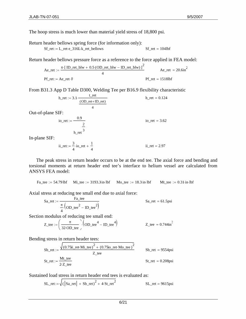
The hoop stress is much lower than material yield stress of 18,800 psi. Return header bellows spring force (for information only):
Sf_ret L_ret e_316L⋅ k_ret_bellows⋅:= Sf_ret 104lbf= Return header bellows pressure force as a reference to the force applied in FEA model:
Ae_retπ ID_ret_blw 0.5 OD_ret_blw ID_ret_blw−( )⋅+[ ]2⋅
4:=
Ae_ret 20.6in2
=
Pf_ret Ae_ret P⋅:= Pf_ret 1518lbf= From B31.3 App D Table D300, Welding Tee per B16.9 flexibility characteristic
h_ret 3.1t_ret
OD_ret ID_ret+( )
4
⋅:=
h_ret 0.124=
Out-of-plane SIF: io_ret
0.9
h_ret
2
3
:=
io_ret 3.62=
In-plane SIF: ii_ret
34
io_ret⋅14
+:=
ii_ret 2.97=
The peak stress in return header occurs to be at the end tee. The axial force and bending and
torsional moments at return header end tee’s interface to helium vessel are calculated from ANSYS FEA model:
Fa_tee 54.79 lbf⋅:= Mi_tee 3193.3in⋅ lbf⋅:= Mo_tee 18.3 in⋅ lbf⋅:= Mt_tee 0.31 in⋅ lbf⋅:=
Axial stress at reducing tee small end due to axial force:
Sa_retFa_tee
π
4OD_tee2 ID_tee2
−( )⋅
:=
Sa_ret 61.5psi=
Section modulus of reducing tee small end:
Z_teeπ
32 OD_tee⋅⎛⎜⎝
⎞⎠
OD_tee4 ID_tee4−( )⋅:=
Z_tee 0.744in3
=
Bending stress in return header tees:
Sb_ret0.75ii_ret Mi_tee⋅( )2 0.75io_ret Mo_tee⋅( )2
+
Z_tee:=
Sb_ret 9554psi=
St_retMt_tee2 Z_tee⋅
:=
St_ret 0.208psi=
Sustained load stress in return header end tees is evaluated as:
SL_ret Sa_ret Sb_ret+( )2 4 St_ret2⋅+:= SL_ret 9615psi=
6/21
JLAB-TN-07-051 9/5/2007
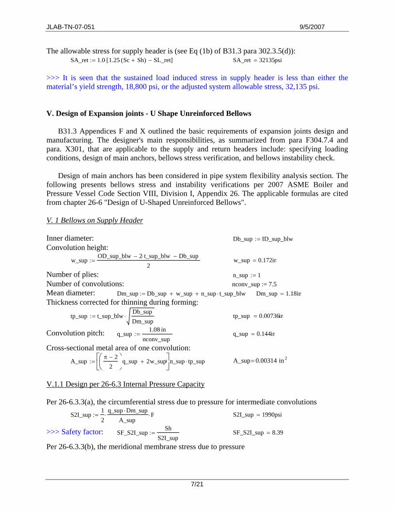
The allowable stress for supply header is (see Eq (1b) of B31.3 para 302.3.5(d)): SA_ret 1.0 1.25 Sc Sh+( )⋅ SL_ret−[ ]⋅:= SA_ret 32135psi=
>>> It is seen that the sustained load induced stress in supply header is less than either the material’s yield strength, 18,800 psi, or the adjusted system allowable stress, 32,135 psi. V. Design of Expansion joints - U Shape Unreinforced Bellows
B31.3 Appendices F and X outlined the basic requirements of expansion joints design and manufacturing. The designer's main responsibilities, as summarized from para F304.7.4 and para. X301, that are applicable to the supply and return headers include: specifying loading conditions, design of main anchors, bellows stress verification, and bellows instability check.
Design of main anchors has been considered in pipe system flexibility analysis section. The
following presents bellows stress and instability verifications per 2007 ASME Boiler and Pressure Vessel Code Section VIII, Division I, Appendix 26. The applicable formulas are cited from chapter 26-6 "Design of U-Shaped Unreinforced Bellows".
V. 1 Bellows on Supply Header Inner diameter: Db_sup ID_sup_blw:=Convolution height:
w_supOD_sup_blw 2 t_sup_blw⋅− Db_sup−
2:=
w_sup 0.172in=
Number of plies: n_sup 1:=Number of convolutions: nconv_sup := 7.5 Mean diameter: Dm_sup Db_sup w_sup+ n_sup t_sup_blw⋅+:= Dm_sup 1.18in= Thickness corrected for thinning during forming:
tp_sup t_sup_blwDb_supDm_sup
⋅:=
tp_sup 0.00736in=
Convolution pitch: q_sup1.08 in⋅
nconv_sup:=
q_sup 0.144in=
Cross-sectional metal area of one convolution:
A_supπ 2−
2⎛⎜⎝
⎞⎠
q_sup 2w_sup+⎡⎢⎣
⎤⎥⎦
n_sup tp_sup⋅:=
2in 0.00314A_sup=
V.1.1 Design per 26-6.3 Internal Pressure Capacity Per 26-6.3.3(a), the circumferential stress due to pressure for intermediate convolutions
S2I_sup12
q_sup Dm_sup⋅
A_sup⋅ P⋅:=
S2I_sup 1990psi=
>>> Safety factor: SF_S2I_supSh
S2I_sup:=
SF_S2I_sup 8.39=
Per 26-6.3.3(b), the meridional membrane stress due to pressure
7/21
JLAB-TN-07-051 9/5/2007
S3_supw_sup
2 n_sup⋅ tp_sup⋅P⋅:=
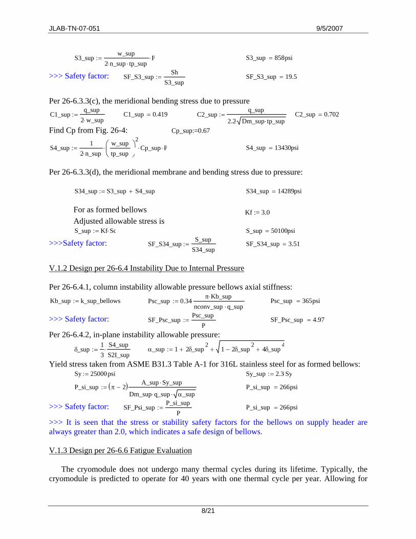
S3_sup 858psi=
>>> Safety factor: SF_S3_supSh
S3_sup:=
SF_S3_sup 19.5=
Per 26-6.3.3(c), the meridional bending stress due to pressure C1_sup
q_sup2 w_sup⋅
:=
C1_sup 0.419= C2_supq_sup
2.2 Dm_sup tp_sup⋅⋅:=
C2_sup 0.702=
Find Cp from Fig. 26-4: Cp_sup:=0.67
S4_sup1
2 n_sup⋅
w_suptp_sup
⎛⎜⎝
⎞⎠
2⋅ Cp_sup⋅ P⋅:=
S4_sup 13430psi=
Per 26-6.3.3(d), the meridional membrane and bending stress due to pressure:
S34_sup S3_sup S4_sup+:= S34_sup 14289psi=
For as formed bellows Kf := 3.0 Adjusted allowable stress is S_sup Kf Sc⋅:= S_sup 50100psi=
>>>Safety factor: SF_S34_supS_sup
S34_sup:=
SF_S34_sup 3.51=
V.1.2 Design per 26-6.4 Instability Due to Internal Pressure Per 26-6.4.1, column instability allowable pressure bellows axial stiffness:
Kb_sup k_sup_bellows:= Psc_sup 0.34π Kb_sup⋅
nconv_sup q_sup⋅⋅:=
Psc_sup 365psi=
>>> Safety factor: SF_Psc_supPsc_sup
P:=
SF_Psc_sup 4.97=
Per 26-6.4.2, in-plane instability allowable pressure:
δ_sup13
S4_supS2I_sup⋅:=
α_sup 1 2δ_sup
2+ 1 2δ_sup
2− 4δ_sup
4++:=
Yield stress taken from ASME B31.3 Table A-1 for 316L stainless steel for as formed bellows: Sy 25000psi⋅:= Sy_sup 2.3 Sy⋅:=
P_si_sup π 2−( ) A_sup Sy_sup⋅
Dm_sup q_sup⋅ α_sup⋅:=
P_si_sup 266psi=
>>> Safety factor: SF_Psi_supP_si_sup
P:=
P_si_sup 266psi=
>>> It is seen that the stress or stability safety factors for the bellows on supply header are always greater than 2.0, which indicates a safe design of bellows. V.1.3 Design per 26-6.6 Fatigue Evaluation
The cryomodule does not undergo many thermal cycles during its lifetime. Typically, the cryomodule is predicted to operate for 40 years with one thermal cycle per year. Allowing for
8/21
JLAB-TN-07-051 9/5/2007
certain safety margins, a conservative estimation of the maximum number of cycles is 100. The fatigue design conducted as follows is mainly for information. The allowable thermal cycle calculation is based on the magnitude of axial elongation, ∆q, of the bellows under working condition. The ANSYS model fails to predict the accurate bellows axial elongation since the bellows is modeled as a straight pipe with axial stiffness. Ideally, a corrugated bellows shall be modeled to improve the accuracy.
The allowable thermal cycle calculations presented herein and hereafter are based on ∆q’s
from ANSYS FEA model. They are conservative in that the axial displacements of the bellows are very possibly exaggerated. The results are for information only. 26-6.6.1 Calculation of stresses due to the total equivalent axial displacement range ∆q of each convolution. The maximum overall displacement in supply header bellows is found in previous piping flexibility analysis FEA model: ∆q_tot_sup 0.167 in⋅:= In each convolution: ∆q_sup
∆q_tot_supnconv_sup
:=
∆q_sup 0.022in=
316L stainless steel Young's modulus @ 2K is: Eb 3.0147107⋅ psi⋅:=
316L stainless steel Young's modulus @ 300K is: Eo 2.8269107⋅ psi⋅:=
(a) Meridional membrane stress:
Cf interpolated from Fig. 26-5: Cf_sup := 1.4
S5_sup12
Eb tp_sup 2⋅
w_sup 3 Cf_sup⋅⋅ ∆q_sup⋅:=
S5_sup 2555psi=
(b) Meridional bending stress:
Cd interpolated from Fig. 26-6 Cd_sup := 1.7
S6_sup53
Eb tp_sup⋅
w_sup 2 Cd_sup⋅⋅ ∆q_sup⋅:=
S6_sup 163829psi=
26-6.6.2 Calculation of the total stress range due to cyclic displacement
St_sup 0.7 S3_sup S4_sup+( )⋅ S5_sup S6_sup+( )+:= St_sup 176387psi= 26-6.6.3 Calculation of allowable number of cycles
Ko 5.2 106⋅ psi⋅:= So 38300psi⋅:= 2.0 :Kg_sup =
Sg_sup Kg_supEoEb⋅ St_sup⋅:=
Sg_sup 330797psi=
The allowed thermal cycles for bellows in supply header is then calculated as:
Nalw_supKo
Kg_supEoEb⋅ St_sup⋅ So−
⎛⎜⎜⎝
⎞
⎠
2:=
Nalw_sup 316=
9/21
JLAB-TN-07-051 9/5/2007
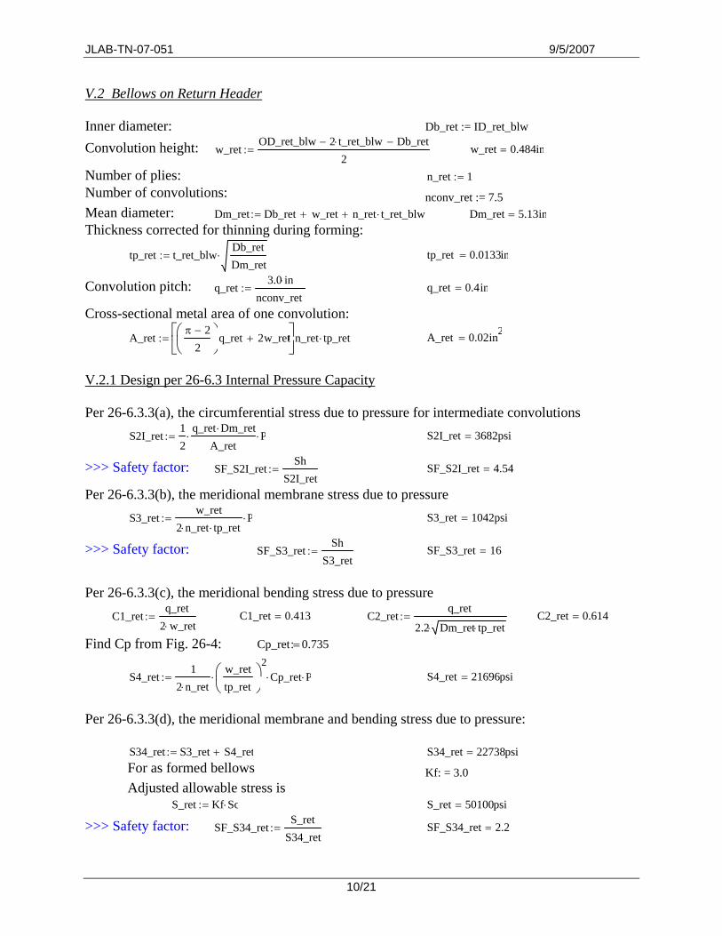
V.2 Bellows on Return Header Inner diameter: Db_ret := ID_ret_blw Convolution height: w_ret
OD_ret_blw 2 t_ret_blw⋅− Db_ret−
2:=
w_ret 0.484in=
Number of plies: n_ret 1:=Number of convolutions: nconv_ret := 7.5 Mean diameter: Dm_ret Db_ret w_ret+ n_ret t_ret_blw⋅+:= Dm_ret 5.13in= Thickness corrected for thinning during forming:
tp_ret t_ret_blwDb_retDm_ret
⋅:=
tp_ret 0.0133in=
Convolution pitch: q_ret3.0 in⋅
nconv_ret:=
q_ret 0.4in=
Cross-sectional metal area of one convolution:
A_retπ 2−
2⎛⎜⎝
⎞⎠
q_ret 2w_ret+⎡⎢⎣
⎤⎥⎦
n_ret tp_ret⋅:=
A_ret 0.02in2=
V.2.1 Design per 26-6.3 Internal Pressure Capacity Per 26-6.3.3(a), the circumferential stress due to pressure for intermediate convolutions
S2I_ret12
q_ret Dm_ret⋅
A_ret⋅ P⋅:=
S2I_ret 3682psi=
>>> Safety factor: SF_S2I_retSh
S2I_ret:=
SF_S2I_ret 4.54=
Per 26-6.3.3(b), the meridional membrane stress due to pressure S3_ret
w_ret2 n_ret⋅ tp_ret⋅
P⋅:=
S3_ret 1042psi=
>>> Safety factor: SF_S3_retSh
S3_ret:=
SF_S3_ret 16=
Per 26-6.3.3(c), the meridional bending stress due to pressure
C1_retq_ret
2 w_ret⋅:=
C1_ret 0.413= C2_ret
q_ret
2.2 Dm_ret tp_ret⋅⋅:=
C2_ret 0.614=
Find Cp from Fig. 26-4: 0.735:Cp_ret =
S4_ret1
2 n_ret⋅
w_rettp_ret
⎛⎜⎝
⎞⎠
2⋅ Cp_ret⋅ P⋅:=
S4_ret 21696psi=
Per 26-6.3.3(d), the meridional membrane and bending stress due to pressure:
S34_ret S3_ret S4_ret+:= S34_ret 22738psi= For as formed bellows Kf: = 3.0 Adjusted allowable stress is
S_ret Kf Sc⋅:= S_ret 50100psi= >>> Safety factor: SF_S34_ret
S_retS34_ret
:=
SF_S34_ret 2.2=
10/21
JLAB-TN-07-051 9/5/2007
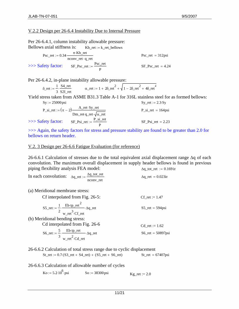
V.2.2 Design per 26-6.4 Instability Due to Internal Pressure Per 26-6.4.1, column instability allowable pressure: Bellows axial stiffness is: Kb_ret k_ret_bellows:=
Psc_ret 0.34π Kb_ret⋅
nconv_ret q_ret⋅⋅:=
Psc_ret 312psi=
>>> Safety factor: SF_Psc_retPsc_ret
P:=
SF_Psc_ret 4.24=
Per 26-6.4.2, in-plane instability allowable pressure:
δ_ret13
S4_retS2I_ret⋅:=
α_ret 1 2δ_ret
2+ 1 2δ_ret
2− 4δ_ret
4++:=
Yield stress taken from ASME B31.3 Table A-1 for 316L stainless steel for as formed bellows: Sy 25000psi⋅:= Sy_ret 2.3 Sy⋅:=
P_si_ret π 2−( ) A_ret Sy_ret⋅
Dm_ret q_ret⋅ α_ret⋅:=
P_si_ret 164psi=
>>> Safety factor: SF_Psi_retP_si_ret
P:=
SF_Psi_ret 2.23=
>>> Again, the safety factors for stress and pressure stability are found to be greater than 2.0 for bellows on return header. V.2. 3 Design per 26-6.6 Fatigue Evaluation (for reference) 26-6.6.1 Calculation of stresses due to the total equivalent axial displacement range ∆q of each convolution. The maximum overall displacement in supply header bellows is found in previous piping flexibility analysis FEA model: ∆q_tot_ret 0.169 in⋅:=
In each convolution: ∆q_ret∆q_tot_retnconv_ret
:=
∆q_ret 0.023in=
(a) Meridional membrane stress:
Cf interpolated from Fig. 26-5: Cf_ret := 1.47
S5_ret12
Eb tp_ret 2⋅
w_ret3 Cf_ret⋅⋅ ∆q_ret⋅:=
S5_ret 594psi=
(b) Meridional bending stress: Cd interpolated from Fig. 26-6 Cd_ret := 1.62
S6_ret53
Eb tp_ret⋅
w_ret2 Cd_ret⋅⋅ ∆q_ret⋅:=
S6_ret 50897psi=
26-6.6.2 Calculation of total stress range due to cyclic displacement
St_ret 0.7 S3_ret S4_ret+( )⋅ S5_ret S6_ret+( )+:= St_ret 67407psi= 26-6.6.3 Calculation of allowable number of cycles
Ko 5.2 106⋅ psi⋅:= So 38300psi⋅:= Kg_ret := 2.0
11/21
JLAB-TN-07-051 9/5/2007
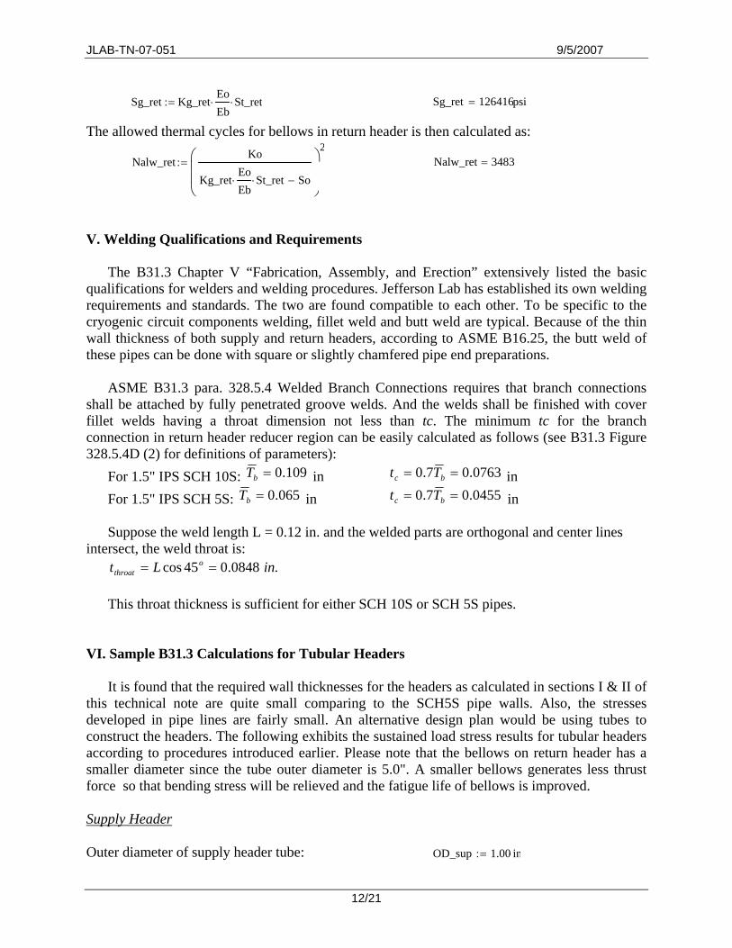
Sg_ret Kg_retEoEb⋅ St_ret⋅:=
Sg_ret 126416psi=
The allowed thermal cycles for bellows in return header is then calculated as:
Nalw_retKo
Kg_retEoEb⋅ St_ret⋅ So−
⎛⎜⎜⎝
⎞
⎠
2:=
Nalw_ret 3483=
V. Welding Qualifications and Requirements
The B31.3 Chapter V “Fabrication, Assembly, and Erection” extensively listed the basic qualifications for welders and welding procedures. Jefferson Lab has established its own welding requirements and standards. The two are found compatible to each other. To be specific to the cryogenic circuit components welding, fillet weld and butt weld are typical. Because of the thin wall thickness of both supply and return headers, according to ASME B16.25, the butt weld of these pipes can be done with square or slightly chamfered pipe end preparations.
ASME B31.3 para. 328.5.4 Welded Branch Connections requires that branch connections
shall be attached by fully penetrated groove welds. And the welds shall be finished with cover fillet welds having a throat dimension not less than tc. The minimum tc for the branch connection in return header reducer region can be easily calculated as follows (see B31.3 Figure 328.5.4D (2) for definitions of parameters):
For 1.5" IPS SCH 10S: 109.0=bT in 0763.07.0 == bc Tt in For 1.5" IPS SCH 5S: 065.0=bT in 0455.07.0 == bc Tt in
Suppose the weld length L = 0.12 in. and the welded parts are orthogonal and center lines
intersect, the weld throat is: .0848.045cos inLt o
throat == This throat thickness is sufficient for either SCH 10S or SCH 5S pipes.
VI. Sample B31.3 Calculations for Tubular Headers
It is found that the required wall thicknesses for the headers as calculated in sections I & II of this technical note are quite small comparing to the SCH5S pipe walls. Also, the stresses developed in pipe lines are fairly small. An alternative design plan would be using tubes to construct the headers. The following exhibits the sustained load stress results for tubular headers according to procedures introduced earlier. Please note that the bellows on return header has a smaller diameter since the tube outer diameter is 5.0". A smaller bellows generates less thrust force so that bending stress will be relieved and the fatigue life of bellows is improved.
Supply Header Outer diameter of supply header tube: OD_sup 1.00 in⋅:=
12/21
JLAB-TN-07-051 9/5/2007
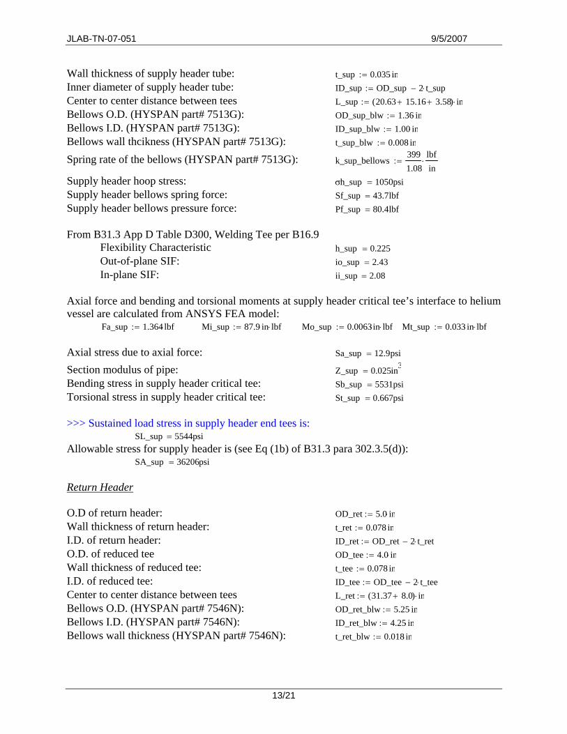
Wall thickness of supply header tube: t_sup 0.035 in⋅:= Inner diameter of supply header tube: ID_sup OD_sup 2 t_sup⋅−:=Center to center distance between tees L_sup 20.63 15.16+ 3.58+( ) in⋅:= Bellows O.D. (HYSPAN part# 7513G): OD_sup_blw 1.36 in⋅:= Bellows I.D. (HYSPAN part# 7513G): ID_sup_blw 1.00 in⋅:= Bellows wall thcikness (HYSPAN part# 7513G): t_sup_blw 0.008 in⋅:= Spring rate of the bellows (HYSPAN part# 7513G): k_sup_bellows
3991.08
lbfin
⋅:=
Supply header hoop stress: σh_sup 1050psi=Supply header bellows spring force: Sf_sup 43.7lbf= Supply header bellows pressure force : Pf_sup 80.4lbf= From B31.3 App D Table D300, Welding Tee per B16.9
Flexibility Characteristic h_sup 0.225= Out-of-plane SIF: io_sup 2.43= In-plane SIF: ii_sup 2.08=
Axial force and bending and torsional moments at supply header critical tee’s interface to helium vessel are calculated from ANSYS FEA model:
Fa_sup 1.364 lbf⋅:= Mi_sup 87.9 in⋅ lbf⋅:= Mo_sup 0.0063in⋅ lbf⋅:= Mt_sup 0.033 in⋅ lbf⋅:= Axial stress due to axial force: Sa_sup 12.9psi= Section modulus of pipe: Z_sup 0.025in3
= Bending stress in supply header critical tee: Sb_sup 5531psi= Torsional stress in supply header critical tee: St_sup 0.667psi= >>> Sustained load stress in supply header end tees is: SL_sup 5544psi=Allowable stress for supply header is (see Eq (1b) of B31.3 para 302.3.5(d)):
SA_sup 36206psi= Return Header O.D of return header: OD_ret 5.0 in⋅:= Wall thickness of return header: t_ret 0.078 in⋅:= I.D. of return header: ID_ret OD_ret 2 t_ret⋅−:=O.D. of reduced tee OD_tee 4.0 in⋅:= Wall thickness of reduced tee: t_tee 0.078 in⋅:= I.D. of reduced tee: ID_tee OD_tee 2 t_tee⋅−:=Center to center distance between tees L_ret 31.37 8.0+( ) in⋅:= Bellows O.D. (HYSPAN part# 7546N): OD_ret_blw 5.25 in⋅:= Bellows I.D. (HYSPAN part# 7546N): ID_ret_blw 4.25 in⋅:= Bellows wall thickness (HYSPAN part# 7546N): t_ret_blw 0.018 in⋅:=
13/21

JLAB-TN-07-051 9/5/2007
Spring rate of the bellows (HYSPAN part# 7546N): k_ret_bellows24773.0
lbfin
⋅:=
Return header hoop stress: σh_ret 2356psi=Return header bellows spring force: Sf_ret 97.65lbf= Return header bellows pressure force Pf_ret = 1302 lbf From B31.3 App D Table D300, Welding Tee per B16.9
Flexibility Characteristic h_ret 0.098= Out-of-plane SIF: io_ret 4.23= In-plane SIF: ii_ret 3.42=
Axial force and bending and torsional moments at return header end tee interfaces to helium vessel are calculated from ANSYS FEA model:
Fa_tee 40.4 lbf⋅:= Mi_tee 2788 in⋅ lbf⋅:= Mo_tee 14.42 in⋅ lbf⋅:= Mt_tee 0.077 in⋅ lbf⋅:= Axial stress at reducing tee small end due to axial force: Sa_ret 42psi= Section modulus of reducing tee small end: Z_tee 0.924in3
= Bending stress in return header end tee: Sb_ret 7737psi= Bending stress in return header end tee: St_ret 0.042psi= >>> Sustained load stress in return header end tees is evaluated as:
SL_ret 7779psi= Allowable stress for supply header is (see Eq (1b) of B31.3 para 302.3.5(d)):
SA_ret 33971psi= Design of Bellows Parameters of bellows on supply headerInner diameter: Db_sup ID_sup_blw:=Convolution height: w_sup 0.172in= Number of plies: n_sup 1:=Number of convolutions: n_conv = 7.5 Mean diameter: Dm_sup 1.18in= Thickness corrected for thinning during forming: tp_sup 0.00736in= Convolution pitch: q_sup 0.144in= Cross-sectional meatl area of one convolution: A_sup = 0.00314 in2
Design per 26-6.3 Internal Pressure Capacity Per 26-6.3.3(a), the circumferential stress due to pressure for intermediate convolutions
S2I_sup 1990psi= Safety factor: SF_S2I_sup 8.39=Per 26-6.3.3(b), the meridional membrane stress due to pressure S3_sup 858psi=Safety factor: SF_S3_sup 19.5=Per 26-6.3.3(c), the meridional bending stress due to pressure S4_sup 13430psi=
14/21
JLAB-TN-07-051 9/5/2007
Per 26-6.3.3(d), the meridional membrane and bending stress due to pressure: S34_sup 14289psi=
Safety factor: SF_S34_sup 3.51= Design per 26-6.4 Instability Due to Internal Pressure 26-6.4.1 Column instability allowable pressure: Psc_sup 365psi=Safety factor: SF_Psc_sup 4.97= 26-6.4.2 In-plane instability allowable pressure: P_si_sup 266psi=Safety factor: SF_Psi_sup 3.62= Design per 26-6.6 Fatigue Evaluation (may be waived) 26-6.6.1 Calculation of stresses due to the total equivalent axial displacement range ∆q of each convolution. The maximum displacement in bellows is: ∆q_tot_sup 0.137 in⋅:= in each convolution: ∆q_sup 0.018in= (a) Meridional membrane stress: S5_sup 2096psi=(b) Meridional bending stress: S6_sup 134399psi= 26-6.6.2 Calculation of total stress range due to cyclic displacement
St_sup 146497psi= 26-6.6.3 Calculation of allowable number of cycles Nalw_sup 484= Parameters of bellows on return header Inner diameter: Db_ret ID_ret_blw:= Convolution height: w_ret 0.482in= Number of plies: n_ret 1:=Number of convolutions: nconv_ret := 7.5 Mean diameter: Dm_ret 4.75in= Thickness corrected for thinning during forming: tp_ret = 0.017 in Convolution pitch: q_ret 0.4in= Cross-sectional meatl area of one convolution: A_ret = 0.02 in2
Design per 26-6.3 Internal Pressure Capacity Per 26-6.3.3(a), the circumferential stress due to pressure for intermediate convolutions
S2I_ret 3440psi= Safety factor: SF_S2I_ret 4.86= Per 26-6.3.3(b), the meridional membrane stress due to pressure S3_ret 1040psi= Safety factor: SF_S3_ret 16.1= Per 26-6.3.3(c), the meridional bending stress due to pressure S4_ret 21647psi=
15/21

JLAB-TN-07-051 9/5/2007
Per 26-6.3.3(d), the meridional membrane and bending stress due to pressure: S34_ret 22687psi=
Safety factor: SF_S34_ret 2.21= Design per 26-6.4 Instability Due to Internal Pressure 26-6.4.1 Column instability allowable pressure: Psc_ret 294psi=Safety factor: SF_Psc_ret 4= 26-6.4.2 In-plane instability allowable pressure: P_si_ret 165psi=Safety factor: SF_Psi_ret 2.24= Design per 26-6.6 Fatigue Evaluation (may be waived) 26-6.6.1 Calculation of stresses due to the total equivalent axial displacement range ∆q of each convolution. The maximum displacement in bellows is: ∆q_tot_ret 0.139 in⋅:= in each convolution: ∆q_ret 0.019in= (a) Meridional membrane stress: S5_ret 492psi= (b) Meridional bending stress: S6_ret 42127psi= 26-6.6.2 Calculation of total stress range due to cyclic displacement
Sg_ret 109711psi= 26-6.6.3 Calculation of allowable number of cycles Nalw_ret 5302= REFERENCES
[1]. ASME B31.3-2004 “Process Piping”, ASME code for pressure piping, B31. The American Society of Mechanical Engineers.
[2]. G. E. Woods and R. B. Baguley, “CASTI Guidebook to ASME B31.3”, Fourth Edition, CASTI Publishing Inc.
[3]. 2007 ASME Boiler & Pressure Vessel Code Section VIII, Division 1, Appendix 26, “ Pressure Vessel and Heat Exchanger Expansion Joints”, The American Society of Mechanical Engineers.
[4]. ASME B16.9 “Factory-Made Wrought Steel Buttwelding Fittings”, The American Society of Mechanical Engineers.
[5]. ASME B16.25 “Buttwelding Ends”, The American Society of Mechanical Engineers.
16/21

JLAB-TN-07-051 9/5/2007
Appendix Finite Element Analysis of C100 Cryogenic Circuit
An ANSYS model (see Fig. A-1) of the cryogenic circuit is created to help in the analysis of displacement stress, sustained load stress, and bellows displacements in the supply and return headers.
5" IPS SCH 5S return header run pipe
3/4" IPS SCH 5S return header run pipe
Bellows on return header
Liquid level assembly
B16.9 Tees
Fig. A-1 Finite Element Model of the Cryogenic Circuit
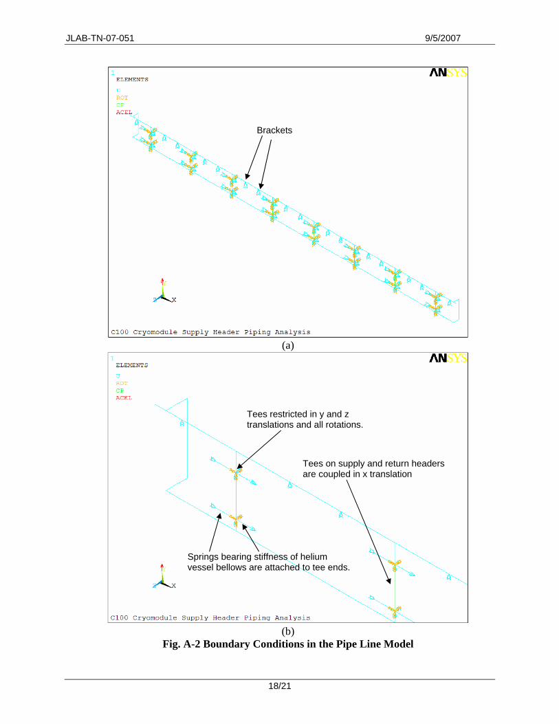
The ends of the tees are almost fixed to the helium vessel except that axial movements are restrained by a few pairs of springs (see Fig. A-2). The tees on supply and return headers are “coupled” so that axial translations will be identical, as if connected through the helium vessel shell. Along the return header, there are a series of brackets that supply vertical supports to the pipe line (Fig. 1).
The nonlinear Young’s modulus and the instantaneous coefficient of thermal expansion
(CTE) for 316L stainless steel in the temperature range from 2K (-456.07oF) to 300K (80.33 oF) are cited from National Institute of Standards and Technology cryogenic properties webpage (http://cryogenics.nist.gov/MPropsMAY/material%20properties.htm) and “Brookhaven National Laboratory Selected Cryogenic Data Handbook” (Figs A-3 and A-4).
There are three types of loads that may occur in the pipe lines: temperature, pressure, and
gravity. In the model, these loads can be turned on or off to simulate the temperature only (displacement stress) or pressure plus gravity (sustained load) cases.
17/21
JLAB-TN-07-051 9/5/2007
Brackets
(a)
Tees restricted in y and z translations and all rotations.
Tees on supply and return headers are coupled in x translation
Springs bearing stiffness of helium vessel bellows are attached to tee ends.
(b) Fig. A-2 Boundary Conditions in the Pipe Line Model
18/21

JLAB-TN-07-051 9/5/2007
Fig. A-3 Temperature (oF) Dependent Young’s Modulus (psi) of 316L Stainless Steel
Fig. A-4 Temperature Dependent Instantaneous CTE of 316L Stainless Steel
19/21
JLAB-TN-07-051 9/5/2007
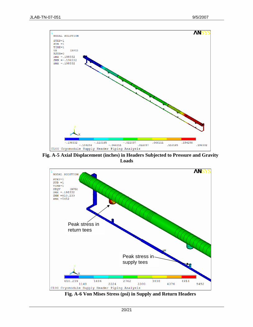
Fig. A-5 Axial Displacement (inches) in Headers Subjected to Pressure and Gravity
Loads
Peak stress in return tees
Peak stress in supply tees
Fig. A-6 Von Mises Stress (psi) in Supply and Return Headers
20/21
JLAB-TN-07-051 9/5/2007
Figure A-5 illustrates the axial displacement in supply and return headers subjected to combined pressure and gravity loads. In Fig. A-6, von Mises stresses in end tees are shown in contour plot. It is seen that in the region where liquid level assembly connects to return header, the stress is in the range from 2,762 psi to 3,300 psi. That is far less than the material’s yield stress of 18,800 psi so that detailed stress analysis is not required. The peak von Mises stress in return header is around 5,500 ksi. This stress level is far below the 316L stainless steel’s yield stress of 18,800 psi. In summary, the headers are safe when combined pressure and gravity loads are exerted.
The highest stress occurs on the supply header at the second tee in from the ends. The stress
in the tee is the result of return header bellows thrust force. This force is transmitted through the outboard helium vessel shell, across the supply bellows, pulling on the run of the tee. The outmost supply tee doesn’t experience this type of force since the liquid level stand pipe rigidly attaches the supply and return headers.
21/21


![C100 Cryomodule End Can Pipeline Design per ASME B31tnweb.jlab.org/tn/2009/09-002.doc · Web viewRules in ASME B&PV code [2] Section VIII “Rules for Construction of Pressure Vessels”](https://static.fdocuments.us/doc/165x107/5ac0817e7f8b9aca388bfb16/c100-cryomodule-end-can-pipeline-design-per-asme-viewrules-in-asme-bpv-code-2.jpg)