Cryogenic Considerations for Cryomodule Design - Pages · Cryogenic Considerations for Cryomodule...
70
Cryogenic Considerations for Cryomodule Design Tom Peterson, SLAC USPAS January 2017
-
Upload
truongkhuong -
Category
Documents
-
view
221 -
download
0
Transcript of Cryogenic Considerations for Cryomodule Design - Pages · Cryogenic Considerations for Cryomodule...
Cryogenic Considerations for
Cryomodule Design
Tom Peterson, SLAC
USPAS
January 2017

January, 2017
USPAS
Cryomodule Design
Tom Peterson
2
Outline
• Introductory comments about considerations for
cryomodule design and helium flow
• Practical superfluid heat transport considerations
• Overview of typical cryomodule requirements
• Stand-alone versus long cryogenic string
• Survey of cryomodule configurations

January, 2017
USPAS
Cryomodule Design
Tom Peterson
3
Cryomodule requirements --
major components • Dressed RF cavities
• RF power input couplers
• Intermediate temperature thermal shield or shields
• Heat exchanger for 4.5 K to 2.2 K precooling of the liquid supply flow if stand-alone style
• Cryogenic valves if stand-alone style
– 2.0 K liquid level control valve
– Cool-down/warm-up valve
– 5 K thermal intercept flow control valve
• Pipe and cavity support structure
• Instrumentation -- RF, pressure, temperature, etc.
• Bayonet connections for helium supply and return
January, 2017
USPAS
Cryomodule Design
Tom Peterson
4
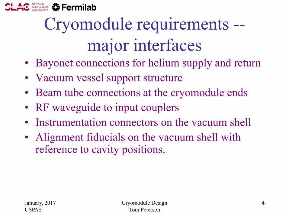
Cryomodule requirements --
major interfaces • Bayonet connections for helium supply and return
• Vacuum vessel support structure
• Beam tube connections at the cryomodule ends
• RF waveguide to input couplers
• Instrumentation connectors on the vacuum shell
• Alignment fiducials on the vacuum shell with reference to cavity positions.

January, 2017
USPAS
Cryomodule Design
Tom Peterson
5
Design considerations
• Cooling arrangement for integration into cryo system
• Pipe sizes for steady-state and emergency venting
• Pressure stability factors
– Liquid volume, vapor volume, liquid-vapor surface area as buffers
for pressure change
• Evaporation or condensation rates with pressure change
• Heat load estimates and uncertainty
• Options for handling 4.5 K (or perhaps 5 K - 8 K) thermal
intercept flow
• Alignment and support stability
• Thermal contraction and fixed points with closed ends

January, 2017
USPAS
Cryomodule Design
Tom Peterson
6
CW cryomodule requirements 1 A “stand-alone” cryomodule is closed at each end, individual insulating
vacuums, with warm beam pipe and magnets in between cryomodules such that individual cryomodules can be warmed up and removed while adjacent cryomodules are cold.
2 Provide the required insulating and beam vacuum reliably
3 Minimize cavity vibration and coupling of external sources to cavities
4 Provide good cavity alignment (typically <0.5 mm)
5 Allow removal of up to 250 W at 2 K per cryomodule if CW
6 Protect the helium and vacuum spaces including the RF cavity from exceeding
allowable pressures. 7 Intercept significant heat loads at intermediate temperatures above 2.0 K to the
extent possible (cavity internal power generation cannot be intercepted)
8 Provide high reliability in all aspects of the cryomodule (vacuum, alignment stability, mechanics, instrumentation) including after thermal cycles
9 Provide excellent magnetic shielding for high Q0
10 Minimize cost (construction and operational)
January, 2017
USPAS
Cryomodule Design
Tom Peterson
7
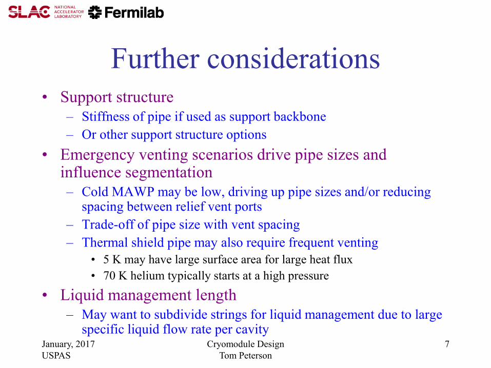
Further considerations • Support structure
– Stiffness of pipe if used as support backbone
– Or other support structure options
• Emergency venting scenarios drive pipe sizes and influence segmentation
– Cold MAWP may be low, driving up pipe sizes and/or reducing spacing between relief vent ports
– Trade-off of pipe size with vent spacing
– Thermal shield pipe may also require frequent venting
• 5 K may have large surface area for large heat flux
• 70 K helium typically starts at a high pressure
• Liquid management length
– May want to subdivide strings for liquid management due to large specific liquid flow rate per cavity
January, 2017
USPAS
Cryomodule Design
Tom Peterson
8
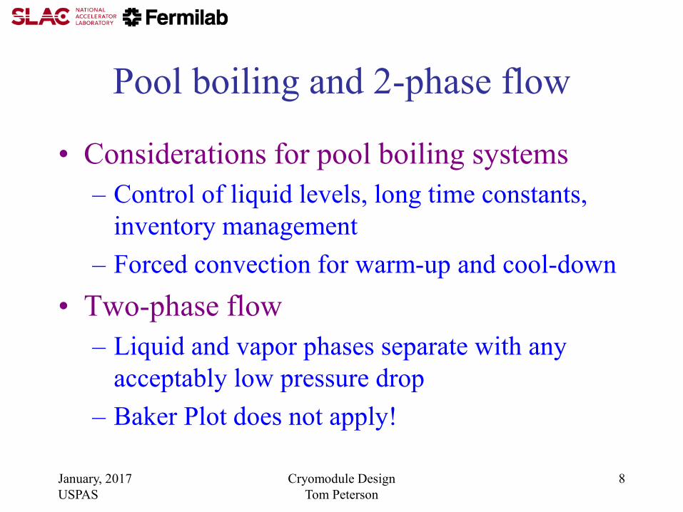
Pool boiling and 2-phase flow
• Considerations for pool boiling systems
– Control of liquid levels, long time constants,
inventory management
– Forced convection for warm-up and cool-down
• Two-phase flow
– Liquid and vapor phases separate with any
acceptably low pressure drop
– Baker Plot does not apply!

January, 2017
USPAS
Cryomodule Design
Tom Peterson
9
Provisions for cool-down and warm-up
• Cool-down
– Return vapor may block liquid supply flow in the same channel; a simple fill from the top or one end might not work. A cool-down vent and/or a bottom-fill port may be required.
• Warm-up
– Flow will stratify. Local electric heat, a bottom vent port, or other feature to force heat down to the lower parts of a cold mass may be required.
• The small “capillary” tubes connected to a manifold and providing helium to the bottoms of helium vessels in TESLA-style cryomodules were included primarily with warm-up in mind
January, 2017
USPAS
Cryomodule Design
Tom Peterson
10
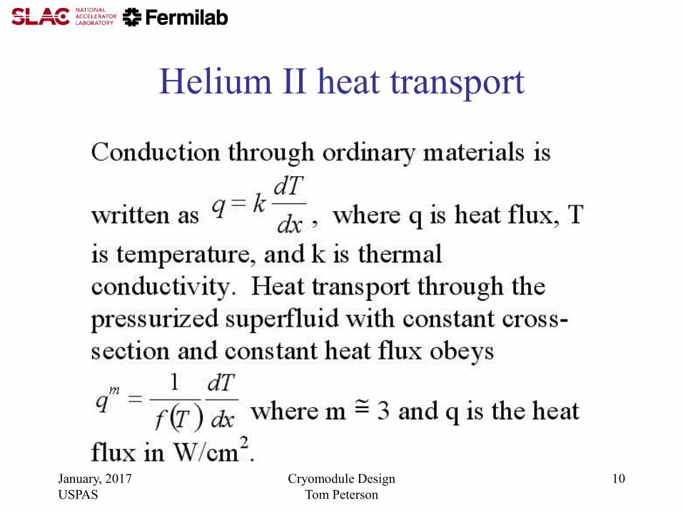
Helium II heat transport
January, 2017
USPAS
Cryomodule Design
Tom Peterson
11
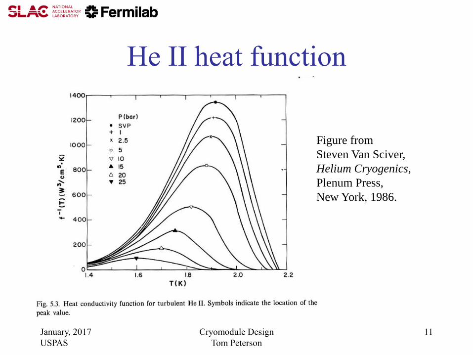
He II heat function
Figure from
Steven Van Sciver,
Helium Cryogenics,
Plenum Press,
New York, 1986.

January, 2017
USPAS
Cryomodule Design
Tom Peterson
12
Helium II heat transport --
near saturation pressure

January, 2017
USPAS
Cryomodule Design
Tom Peterson
13
2-pipe 2 Kelvin vapor system
650 MHz cryomodule a modified TESLA-type

January, 2017
USPAS
Cryomodule Design
Tom Peterson
14
TTF cryomodule cross-section

January, 2017
USPAS
Cryomodule Design
Tom Peterson
15
Heat transport vertically to surface
Recall from our normal fluids behavior discussion, the
pressure head of liquid helium and Clapeyron Equation tell us
that helium saturation temperature increases by about 1.5
mK/cm of depth.
Substituting 0.0015 K/cm into equation (3) on slide 12
results in 1.2 W/cm2 heat flux vertically to the surface of the
helium II. Note that this heat flux is essentially independent of
depth for the depths of 10’s of cm typical of RF helium
vessels. I use 1 W/cm2 as a limit for sizing a conduit for heat
transport to the surface of a saturated helium II bath.

January, 2017
USPAS
Cryomodule Design
Tom Peterson
16
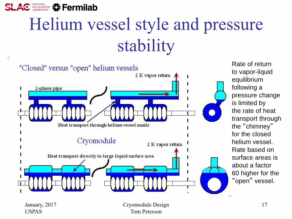
Helium vessel style • Helium vessel style (open vs. closed) is independent of
support style (hung from 300 mm pipe, space frame, rails)
• High heat loads and tight pressure stability ==>
– Large liquid-vapor surface area for liquid-vapor equilibrium
– Acts as thermal/pressure buffer with heat and pressure changes
• Linac is short enough that total helium inventory not an issue ==>
– Open helium vessel is feasible
• For the stand-alone CW cryomodule, a closed TESLA-type helium vessel may be favored by
– Tuner design
– Input coupler design
– And allowed by reduced pressure sensitivity
January, 2017
USPAS
Cryomodule Design
Tom Peterson
17
Helium vessel style and pressure
stability Rate of return
to vapor-liquid
equilibrium
following a
pressure change
is limited by
the rate of heat
transport through
the “chimney”
for the closed
helium vessel.
Rate based on
surface areas is
about a factor
60 higher for the
“open” vessel.

January, 2017
USPAS
Cryomodule Design
Tom Peterson
18
Cryomodule Pipe Sizing Criteria • Heat transport from cavity to 2-phase pipe
– 1 Watt/cm2 is a conservative rule for a vertical pipe (less heat flux with horizontal lengths)
• Two phase pipe size
– 5 meters/sec vapor “speed limit” over liquid
– Not smaller than nozzle from helium vessel
• Gas return pipe (also serves as the support pipe in TESLA-style CM)
– Pressure drop < 10% of total pressure in normal operation
– Support structure considerations
• Loss of vacuum venting P < cold MAWP at cavity
– Path includes nozzle from helium vessel, 2-phase pipe, may include gas return pipe, and any external vent lines
January, 2017
USPAS
Cryomodule Design
Tom Peterson
19
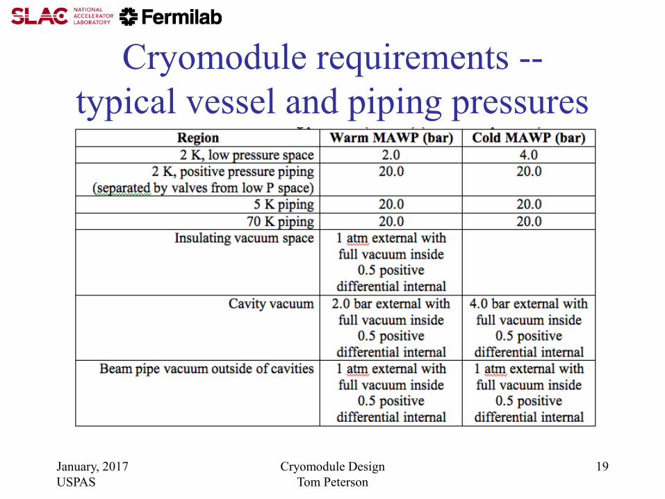
Cryomodule requirements --
typical vessel and piping pressures

January, 2017
USPAS
Cryomodule Design
Tom Peterson
20
Pressure-induced pipe instability

January, 2017
USPAS
Cryomodule Design
Tom Peterson
21
Lateral elastic pipe instability
• Lateral displacement force is proportional to
lateral displacement and to pressure
• If the restoring spring constant of the piping
system in which the bellows is installed is less
than the constant relating lateral displacement
force to lateral displacement (a “negative spring
constant”) at a given pressure, the system is
transversely, elastically unstable at that pressure.
• Relatively light pipe supports near the bellows can
prevent this instability by adding stiffness.
January, 2017
USPAS
Cryomodule Design
Tom Peterson
22
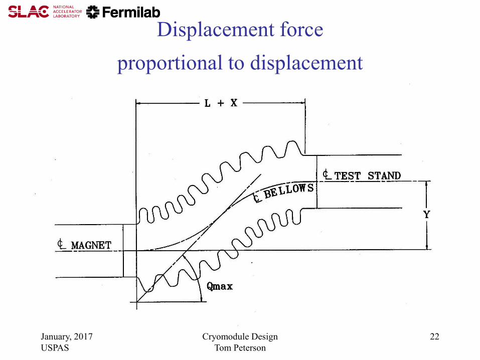
Displacement force
proportional to displacement
January, 2017
USPAS
Cryomodule Design
Tom Peterson
23
Pipe instability analysis
• Lateral pipe instability: displacement force is proportional to displacement (unpublished paper by P.O. Mazur, Fermilab)
• F(P) = PAsin(Qmax) where F(P) is the lateral force as a function of pressure, P is pressure in the system (vacuum outside), A is bellows areas, and Qmax is the maximum angle of displaced convolutions
• Qmax = 3Y/(2(L+X)), where X, Y, and L are shown in the previous figure
• For small angles, F(P)/Y = 3 PA/(2(L+X))
• Instability occurs when F(P)/Y exceeds the restoring spring constant, determined by bellows and pipe stiffness

January, 2017
USPAS
Cryomodule Design
Tom Peterson
24
US LHC high gradient quad (Q2P1) cold mass,
support rings, and internal piping
(from Tom Nicol, Fermilab)
Pipe supports are added
at each end and at the
center for stability
January, 2017
USPAS
Cryomodule Design
Tom Peterson
25
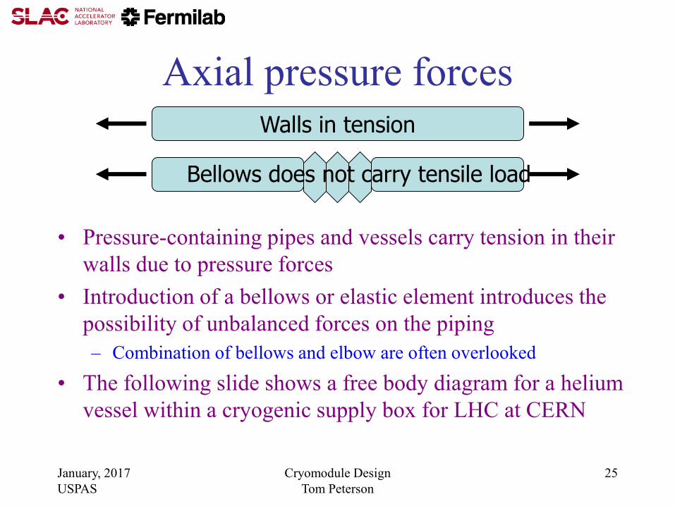
Axial pressure forces
• Pressure-containing pipes and vessels carry tension in their
walls due to pressure forces
• Introduction of a bellows or elastic element introduces the
possibility of unbalanced forces on the piping
– Combination of bellows and elbow are often overlooked
• The following slide shows a free body diagram for a helium
vessel within a cryogenic supply box for LHC at CERN
Walls in tension
Bellows does not carry tensile load

January, 2017
USPAS
Cryomodule Design
Tom Peterson
26
20.0 kN
(4500 lbf)
10.0 kN (2250 lbf) x 2
635 mm
(25.0 in)
767 mm
(30.2 in) 12.5 kN (2820 lbf) x 2
(rods in tension)
66.8 kN (15000 lbf)
(Combined pressure and gravity)
Forces on DFBX-E due to
20 bar M1 line pressure plus
3.5 bar in the helium vessel
20.8 kN (4680 lbf) x 2
(rods in tension)

January, 2017
USPAS
Cryomodule Design
Tom Peterson
27
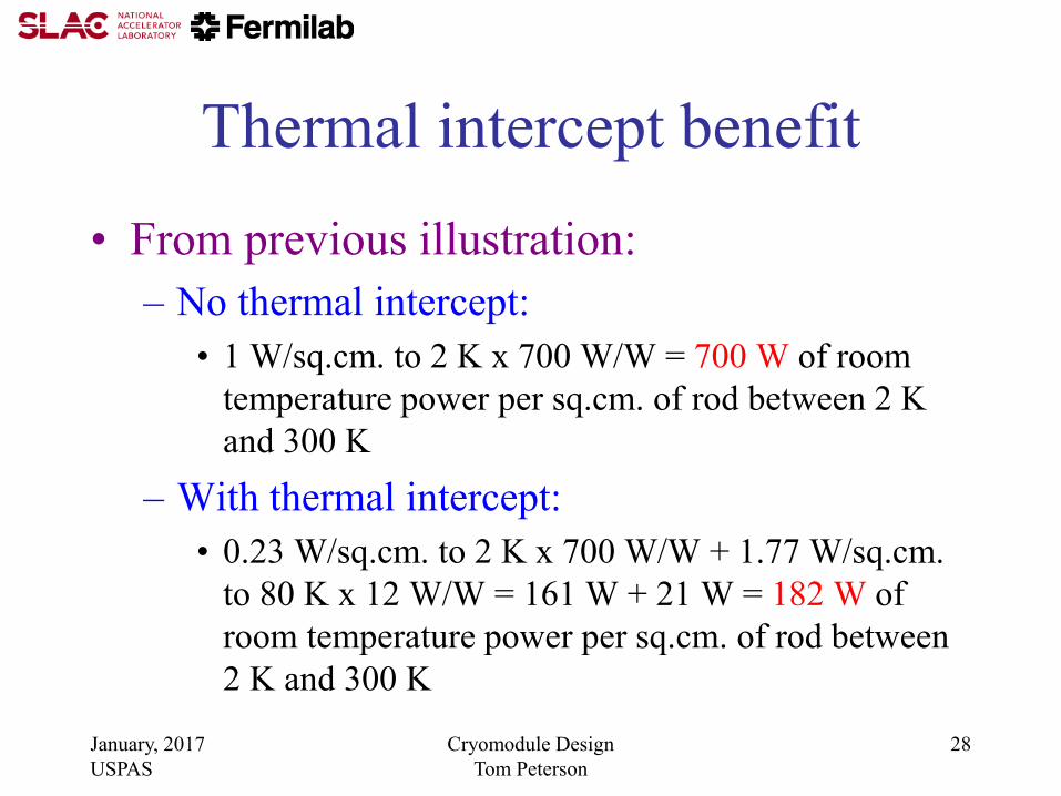
Thermal intercepts Stainless steel in pure conduction
0.0
50.0
100.0
150.0
200.0
250.0
300.0
0.00 0.20 0.40 0.60 0.80 1.00
Position
Tem
peratu
re (
K)
No intercept
80 K intercept
With no thermal intercept,
assume a heat flux of
1 W/sq.cm. to 2.0 K
Then adding an 80 K intercept
at the midpoint results in
0.23 W/sq.cm. to 2.0 K and
1.77 W/sq.cm. to 80 K
January, 2017
USPAS
Cryomodule Design
Tom Peterson
28
Thermal intercept benefit
• From previous illustration:
– No thermal intercept:
• 1 W/sq.cm. to 2 K x 700 W/W = 700 W of room
temperature power per sq.cm. of rod between 2 K
and 300 K
– With thermal intercept:
• 0.23 W/sq.cm. to 2 K x 700 W/W + 1.77 W/sq.cm.
to 80 K x 12 W/W = 161 W + 21 W = 182 W of
room temperature power per sq.cm. of rod between
2 K and 300 K
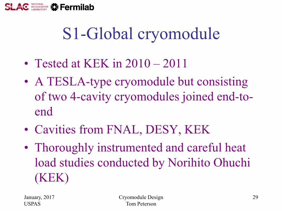
S1-Global cryomodule
• Tested at KEK in 2010 – 2011
• A TESLA-type cryomodule but consisting
of two 4-cavity cryomodules joined end-to-
end
• Cavities from FNAL, DESY, KEK
• Thoroughly instrumented and careful heat
load studies conducted by Norihito Ohuchi
(KEK)
January, 2017
USPAS
Cryomodule Design
Tom Peterson
29

January, 2017
USPAS
Cryomodule Design
Tom Peterson
30
From Norihito Ohuchi (KEK)

Measured thermal radiation heat
• Measured in above-mentioned S1-Global
studies at KEK
– 1.62 W/m2 from 300 K to 80 K thermal shield
– 0.045 W/m2 from 80 K thermal shield to 5 K
thermal shield
• My “rule of thumb” (pre-dates S1-Global)
– 1.5 W/m2 from 300 K to 80 K thermal shield
– 0.05 W/m2 from 80 K thermal shield to 5 K
thermal shield January, 2017
USPAS
Cryomodule Design
Tom Peterson
31

January, 2017 USPAS Cryomodule Design Tom Peterson
32
Pre-accelerator
Electron side Positron side
Beamdelivery
Electron linac
Cryo-unit
Undulator
Positron linac
RTML RTML
Crab-cavity
Final doublet
Booster
Keep-alive
DR cavities
DR wigglersDamping
ring 2 K cryoplants
4.5 K cryoplants
Distribution boxes
Legend:
Transfer lines
Pre-acceleratorBooster
Keep-alive
Electron side Positron side
Beamdelivery
Electron linac
Cryo-unit
Undulator
DR cavities
DR wigglers
Positron linac
RTML RTML
Crab-cavity
Final doublet
Dampingring
Dampingring
BaselineConfiguration
Layout
ReferenceDesignLayout

January, 2017 USPAS Cryomodule Design Tom Peterson
33
Cryogenic unit length limitations
• 25 KW total equivalent 4.5 K capacity – Heat exchanger sizes
– Over-the-road sizes
– Experience
• Cryomodule piping pressure drops with 2+ km distances
• Cold compressor capacities
• With 192 modules, we reach our plant size limits, cold compressor limits, and pressure drop limits
• 192 modules results in 2.47 km long cryogenic unit
• 5 units (not all same length) per 250 GeV linac – Divides linac nicely for undulators at 150 GeV

January, 2017 USPAS Cryomodule Design Tom Peterson
34
Heat loads scaled from
TESLA TDR
Cryomodule ILC 8-8-8 and 9-8-9 refers to the number of cavities in the modules in an RF unit
E, [MV/m] G
Q
Rep rate, [Hz]
Number of Cavities avg number of cavities per module
Fill time [µsec] Tf
Beam pulse [µsec] Tb
Number of bunches Nb
Particles per bunch [1e10] Qb
Gfac Stored Energy Factor = G^2*(Tb + 1.1*Tf)
Pfac Input Power Factor = G*(Tb + 2*Tf)*Cfac
Bfac Bunch Factor = Nb*Qb^2
Cfac Beam Current Factor = Qb*Nb/Tb
2
2820
ILC 9-8-9TESLA
23.4
1.E+10
597
969
5
420
950
12
2670
31.5
1.E+10
5
8.667
2.04
2.09
1.54
0.99
0.95

January, 2017 USPAS Cryomodule Design Tom Peterson
35
Module predicted heat loads -- 2K
Static Dynamic Static Dynamic
Temperature Level
RF load 4.95 7.46 Dynamic load scaled by the number of cavities and Gfac
Supports 0.60 0.60 - Assume independent of nuimber of cavities
Input coupler 0.76 0.14 0.55 0.16 Static load scaled by number of cavities, dynamic by Pfac also
HOM coupler (cables) 0.01 0.27 0.01 0.18 Static and dynamic load scaled by number of cavities, dynamic by Cfac also
HOM absorber 0.14 0.02 0.14 0.01 Dynamic load scaled by Bfac
Beam tube bellows 0.24 0.36 Dynamic load scaled by the number of cavities and Gfac
Current leads 0.04 0.28 0.28 Weigh by a factor of 1/3 since only 1 in 3 modules have quads**
HOM to structure 1.68 1.20 Static load scaled by the number of cavities, dynamic by Bfac also
Coax cable (4) 0.05 0.05 Assume indepent of nuimber of cavities
Instrumentation taps 0.07 0.07 Assume indepent of nuimber of cavities
Scales as Gfac 5.19 7.83
Scales as Pfac 0.14 0.16
Independent of G,Tf 1.67 1.97 1.70 1.68
Static, dynamic sum 1.67 7.30 1.70 9.66 Total for 9-8-9 RF unit below
2K Sum [W] 34.08
2K 2K
9.0 11.4
TESLA ILC 9-8-9
January, 2017 USPAS Cryomodule Design Tom Peterson
36
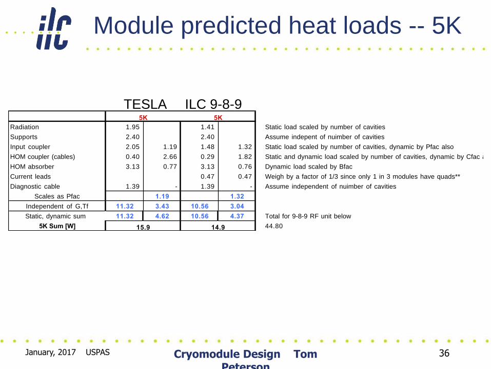
Module predicted heat loads -- 5K
Radiation 1.95 1.41 Static load scaled by number of cavities
Supports 2.40 2.40 Assume indepent of nuimber of cavities
Input coupler 2.05 1.19 1.48 1.32 Static load scaled by number of cavities, dynamic by Pfac also
HOM coupler (cables) 0.40 2.66 0.29 1.82 Static and dynamic load scaled by number of cavities, dynamic by Cfac also
HOM absorber 3.13 0.77 3.13 0.76 Dynamic load scaled by Bfac
Current leads 0.47 0.47 Weigh by a factor of 1/3 since only 1 in 3 modules have quads**
Diagnostic cable 1.39 - 1.39 - Assume independent of nuimber of cavities
Scales as Pfac 1.19 1.32
Independent of G,Tf 11.32 3.43 10.56 3.04
Static, dynamic sum 11.32 4.62 10.56 4.37 Total for 9-8-9 RF unit below
5K Sum [W] 44.80
5K 5K
14.915.9
TESLA ILC 9-8-9

January, 2017 USPAS Cryomodule Design Tom Peterson
37
Module predicted heat loads -- 40K
Radiation 44.99 32.49 Static load scaled by number of cavities
Supports 6.00 6.00 Assume indepent of nuimber of cavities
Input coupler 21.48 59.40 15.51 66.08 Static load scaled by number of cavities, dynamic by Pfac also
HOM coupler (cables) 2.55 13.22 1.84 9.04 Static and dynamic load scaled by number of cavities, dynamic by Cfac also
HOM absorber (3.27) 15.27 (3.27) 15.04 Dynamic load scaled by Bfac
Current leads 4.13 4.13 Weigh by a factor of 1/3 since only 1 in 3 modules have quads**
Diagnostic cable 2.48 2.48 Assume indepent of nuimber of cavities
Scales as Pfac 59.40 66.08
Independent of G,Tf 74.23 28.49 59.19 28.22
Static, dynamic sum 74.23 87.89 59.19 94.30 Total for 9-8-9 RF unit below
40K Sum [W] 460.46
40K 40K
162.1 153.5
TESLA ILC 9-8-9

January, 2017 USPAS Cryomodule Design Tom Peterson
38
Power required for a non-
isothermal load
• Use
• Where P is the ideal room-temperature power
required to remove a non-isothermal heat
load
• I will show the use of this later in calculating
the ILC cryogenic system power
January, 2017 USPAS Cryomodule Design Tom Peterson
39
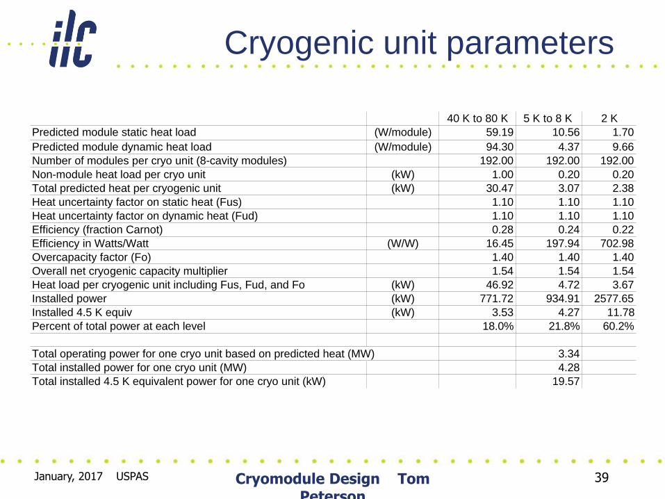
Cryogenic unit parameters
40 K to 80 K 5 K to 8 K 2 K
Predicted module static heat load (W/module) 59.19 10.56 1.70
Predicted module dynamic heat load (W/module) 94.30 4.37 9.66
Number of modules per cryo unit (8-cavity modules) 192.00 192.00 192.00
Non-module heat load per cryo unit (kW) 1.00 0.20 0.20
Total predicted heat per cryogenic unit (kW) 30.47 3.07 2.38
Heat uncertainty factor on static heat (Fus) 1.10 1.10 1.10
Heat uncertainty factor on dynamic heat (Fud) 1.10 1.10 1.10
Efficiency (fraction Carnot) 0.28 0.24 0.22
Efficiency in Watts/Watt (W/W) 16.45 197.94 702.98
Overcapacity factor (Fo) 1.40 1.40 1.40
Overall net cryogenic capacity multiplier 1.54 1.54 1.54
Heat load per cryogenic unit including Fus, Fud, and Fo (kW) 46.92 4.72 3.67
Installed power (kW) 771.72 934.91 2577.65
Installed 4.5 K equiv (kW) 3.53 4.27 11.78
Percent of total power at each level 18.0% 21.8% 60.2%
Total operating power for one cryo unit based on predicted heat (MW) 3.34
Total installed power for one cryo unit (MW) 4.28
Total installed 4.5 K equivalent power for one cryo unit (kW) 19.57

January, 2017 USPAS Cryomodule Design Tom Peterson
40
CERN LHC capacity multipliers
• We have adopted a modified version of the
LHC cryogenic capacity formulation for ILC
• Cryo capacity = Fo x (Qd x Fud + Qs x Fus)
– Fo is overcapacity for control and off-design or
off-optimum operation
– Qs is predicted static heat load
– Fus is uncertainty factor static heat load
estimate
– Fud is uncertainty factor dynamic heat load
estimate
– Qd is predicted dynamic heat load
January, 2017 USPAS Cryomodule Design Tom Peterson
41
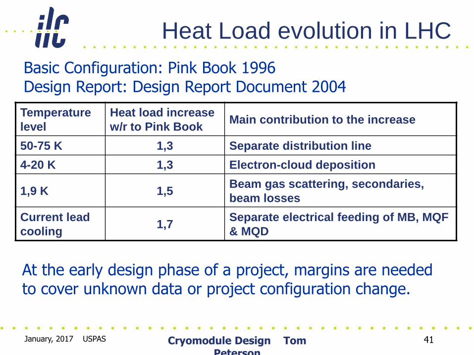
Heat Load evolution in LHC
Temperature
level
Heat load increase
w/r to Pink Book Main contribution to the increase
50-75 K 1,3 Separate distribution line
4-20 K 1,3 Electron-cloud deposition
1,9 K 1,5 Beam gas scattering, secondaries,
beam losses
Current lead
cooling 1,7
Separate electrical feeding of MB, MQF
& MQD
Basic Configuration: Pink Book 1996 Design Report: Design Report Document 2004
At the early design phase of a project, margins are needed to cover unknown data or project configuration change.

January, 2017 USPAS Cryomodule Design Tom Peterson
42
Cryogenic system design
• Fairly complete accounting of cold devices with heat load estimates and locations – Some cold devices still not well defined
– Some heat loads are very rough estimates
• Cryogenic plant capacities have been estimated – Overall margin about 1.54
– Main linac plants dominate, each at 20 kW @ 4.5 K equiv.
• Component conceptual designs (distribution boxes, end boxes, transfer lines) remained sketchy – Need these to define space requirements and make cost
estimates
– Used area system lattice designs to develop transfer line lengths and conceptual cryosystem layouts

January, 2017
USPAS
Cryomodule Design
Tom Peterson
43
Cryomodule string segmentation • Various degrees of possible segmentation
– Total isolation and warm-up with adjacent cryomodule cold
– Total separation of vacuum and cryogenic circuits but no provisions for maintaining segments cold which are adjacent to warm cryomodules
• Limits extent of control lengths and vacuum
• No end buffer from adjacent cold segment for vacuum let-up of warm segment. E.g., one must warm three segments to let up one.
• Segments downstream of warm one may not be held cold
– Vacuum isolation and/or cryo circuit extent of various lengths, not all equal
• For example, liquid flow path shorter than thermal shield circuits
• Some valves distributed more finely than others. May have small “feed boxes” or valves in cryomodules for 2 K liquid supply.
– Relief valve frequency -- low MAWP may force frequent vents
• Pipe sizes trade off with segmentation lengths
January, 2017
USPAS
Cryomodule Design
Tom Peterson
44
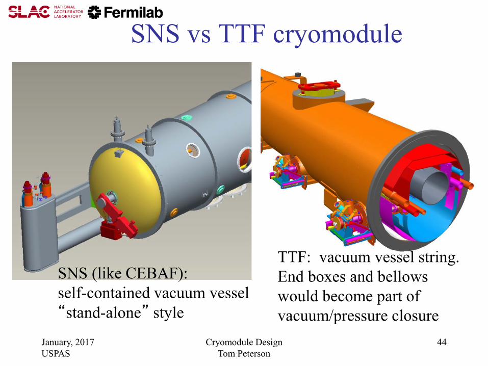
SNS vs TTF cryomodule
TTF: vacuum vessel string.
End boxes and bellows
would become part of
vacuum/pressure closure
SNS (like CEBAF):
self-contained vacuum vessel
“stand-alone” style
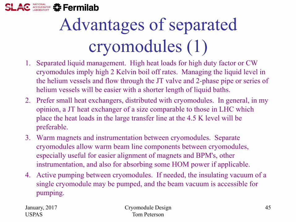
Advantages of separated
cryomodules (1) 1. Separated liquid management. High heat loads for high duty factor or CW
cryomodules imply high 2 Kelvin boil off rates. Managing the liquid level in
the helium vessels and flow through the JT valve and 2-phase pipe or series of
helium vessels will be easier with a shorter length of liquid baths.
2. Prefer small heat exchangers, distributed with cryomodules. In general, in my
opinion, a JT heat exchanger of a size comparable to those in LHC which
place the heat loads in the large transfer line at the 4.5 K level will be
preferable.
3. Warm magnets and instrumentation between cryomodules. Separate
cryomodules allow warm beam line components between cryomodules,
especially useful for easier alignment of magnets and BPM's, other
instrumentation, and also for absorbing some HOM power if applicable.
4. Active pumping between cryomodules. If needed, the insulating vacuum of a
single cryomodule may be pumped, and the beam vacuum is accessible for
pumping.
January, 2017
USPAS
Cryomodule Design
Tom Peterson
45

Advantages of separated
cryomodules (2) 5. Loss of insulating vacuum to air is limited to one cryomodule (assuming vacuum
isolation from the transfer line). The sudden rush of air into insulating vacuum and
resulting heat fluxes with air condensation can deposit up to several Watts per square cm
on liquid helium-temperature vessels and piping, depending on insulation. For a string
of cryomodules, this can result in huge flow rates with requirements for extremely large
vent lines and venting devices. The separate cryomodule vacuums limit this disaster to
one cryomodule for the insulating vacuum loss.
6. Replacement for maintenance. Separate cryomodules allow replacement of individual
cryomodules without warming the entire string.
7. Testing and commissioning. Separate cryomodules allow installation and cryogenic
operation of individual cryomodules or parts of the linac during installation and
commissioning.
8. Incorporation and connection of low-beta cryomodules of different types, for example
FRIB. Separated cryomodules will reduce constraints imposed by matching cold
interconnects and allow easier transitions among different types of cryomodules, also
allowing the top-loading configuration.
January, 2017
USPAS
Cryomodule Design
Tom Peterson
46

January, 2017
USPAS
Cryomodule Design
Tom Peterson
47
Stand-alone
cryomodule
schematic

Advantages of string
1. No external transfer line. A large transfer line with vacuum-jacketed 4 K pumping line
may be $5000 to $10,000 per meter including all the connections to the cryomodules.
So for a 10 meter long cryomodule, it may add the equivalent of another $50K to $100K
or so to the CM cost, as well as occupy tunnel space. I think the external transfer line
cost is the major cost difference between these two configurations. Incorporation of the
transfer line into the cryomodule piping was one of the main motivations for the TESLA
design.
2. Fewer cryogenic valves. By placing the helium vessels and other piping of multiple
cryomodules in series, one valve at a feed or turnaround box controls the flow through
many cryomodules. This may provide significant cost reduction (in addition to the
elimination of the external transfer line) and also simplify operations (assuming control
of the long volumes is not a problem) by resulting in fewer control valves.
3. No warm-cold transitions at the ends. Especially for systems with relatively low
dynamic heat loads where static heat load is more significant, eliminating the warm-cold
transitions at each end helps reduce heat load. It may also result in a simpler end since
one just has a connection to another pipe, no turn-arounds or pressure-load-bearing ends.
However, I do not believe that closing the end is more expensive (as some have
claimed) than the huge vacuum bellows and other features of an interconnect. January, 2017
USPAS
Cryomodule Design
Tom Peterson
48
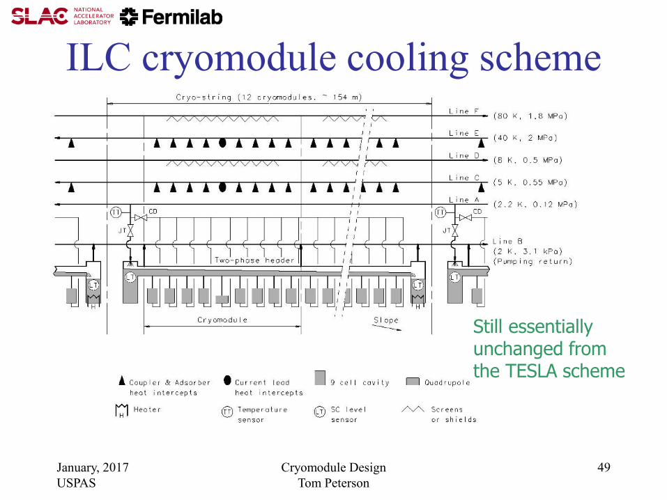
ILC cryomodule cooling scheme
January, 2017
USPAS
Cryomodule Design
Tom Peterson
49
Still essentially unchanged from the TESLA scheme

January, 2017
USPAS
Cryomodule Design
Tom Peterson
50
From Shrikant Pattalwar, STFC Daresbury, UK

January, 2017
USPAS
Cryomodule Design
Tom Peterson
51
Various cryomodule concepts
• Single Spoke Resonator (SSR) cryostat concept using
support posts under the cavities and magnets
• TESLA/ILC
• SNS/Jlab 12 GeV upgrade style “space frame” supports
• Closed-ended “TESLA” style
• BESSY/HZB CW cryomodule string rather than stand-
alone cryomodules
• Cornell’s ERL cryomodule
• ANL/FRIB/TRIUMF-style top-loading rectangular
cryostats

January, 2017
USPAS
Cryomodule Design
Tom Peterson
52
SSR cryomodule concept
Vacuum vessel end removed
Support structure is a cradle on which magnets and cavities are supported
January, 2017
USPAS
Cryomodule Design
Tom Peterson
53
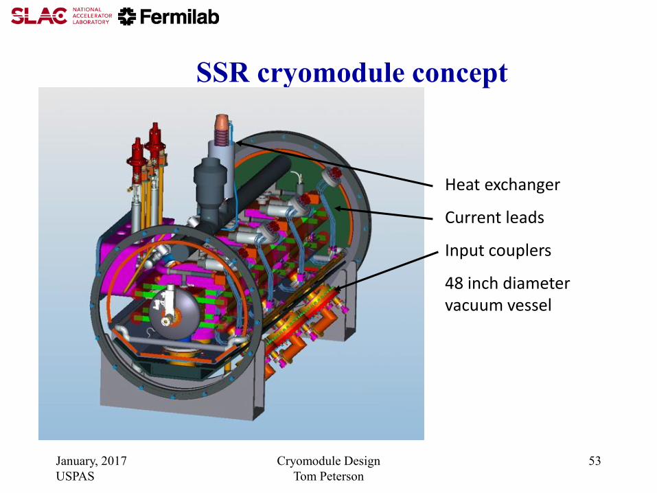
SSR cryomodule concept
Heat exchanger
Current leads
Input couplers
48 inch diameter vacuum vessel
January, 2017
USPAS
Cryomodule Design
Tom Peterson
54
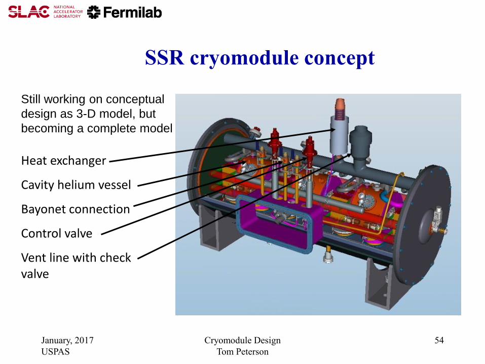
SSR cryomodule concept
Heat exchanger
Cavity helium vessel
Bayonet connection
Control valve
Vent line with check valve
Still working on conceptual
design as 3-D model, but
becoming a complete model

January, 2017
USPAS
Cryomodule Design
Tom Peterson
55
TESLA-style Cryomodule

January, 2017
USPAS
Cryomodule Design
Tom Peterson
56
Cutaway view of cavity within
a cryomodule

January, 2017
USPAS
Cryomodule Design
Tom Peterson
57
Closed ended “TESLA” style

January, 2017
USPAS
Cryomodule Design
Tom Peterson
58

January, 2017
USPAS
Cryomodule Design
Tom Peterson
59
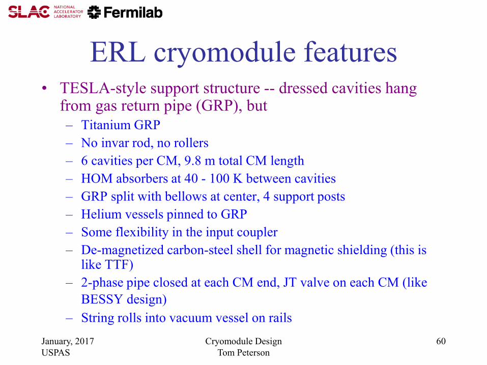
ERL cryomodule features
Figure 1 from CRYOGENIC HEAT LOAD OF THE CORNELL ERL MAIN LINAC CRYOMODULE, by
E. Chojnacki, E. Smith, R. Ehrlich, V. Veshcherevich and S. Chapman, Cornell University, Ithaca, NY, U.S.A.
Published in Proceedings of SRF2009, Berlin, Germany
January, 2017
USPAS
Cryomodule Design
Tom Peterson
60
ERL cryomodule features • TESLA-style support structure -- dressed cavities hang
from gas return pipe (GRP), but
– Titanium GRP
– No invar rod, no rollers
– 6 cavities per CM, 9.8 m total CM length
– HOM absorbers at 40 - 100 K between cavities
– GRP split with bellows at center, 4 support posts
– Helium vessels pinned to GRP
– Some flexibility in the input coupler
– De-magnetized carbon-steel shell for magnetic shielding (this is like TTF)
– 2-phase pipe closed at each CM end, JT valve on each CM (like
BESSY design)
– String rolls into vacuum vessel on rails

61
LCLS-II cryomodule flow scheme
Cryomodule Design Tom Peterson

January, 2017
USPAS
Cryomodule Design
Tom Peterson
62
FRIB cryomodule
“bathtub” style for comparison

January, 2017
USPAS
Cryomodule Design
Tom Peterson
63
TRIUMF cryomodule concept “bathtub” style with 1.3 GHz cavities
for comparison
January, 2017
USPAS
Cryomodule Design
Tom Peterson
64

January, 2017
USPAS
Cryomodule Design
Tom Peterson
65
Conclusions
• Cryomodule must be designed as part of the larger
cryogenic system
• Vacuum and cryogenic line segmentation choices depend
on heat loads as well as various mechanical, alignment,
and reliability considerations
• Off-design requirements such as emergency venting may
determine line sizes and design features
• There is no single best design configuration. A variety of
quite different designs already exist with features
appropriate to the various specific applications
January, 2017
USPAS
Cryomodule Design
Tom Peterson
66
References -- 1
• ASME Boiler & Pressure Vessel Code, 2007 Edition, July 1, 2007
– Primarily Section VIII, Division 1 and Division 2
• ASME B31.3-2008, Process Piping, ASME Code for Pressure Piping
• R. Byron Bird, Warren E. Stewart, Edwin N. Lightfoot, “Transport Phenomena,” John Wiley &Sons, 1960.
• S. W. VanSciver, “Helium Cryogenics,” Plenum Press, 1986.
• CGA S-1.3, “Pressure Relief Device Standards”, Compressed Gas Association, 2005.
January, 2017
USPAS
Cryomodule Design
Tom Peterson
67
References -- 2
• Fermilab’s ES&H Manual (FESHM) pressure vessel
standard, FESHM 5031
– http://esh-docdb.fnal.gov/cgi-bin/ShowDocument?docid=456
• FESHM Chapter 5031.6 - Dressed Niobium SRF Cavity
Pressure Safety
– And associated document: “Guidelines for the Design,
Fabrication, Testing and Installation of SRF Nb Cavities,”
Fermilab Technical Division Technical Note TD-09-005
– http://esh-docdb.fnal.gov/cgi-bin/ShowDocument?docid=1097

January, 2017
USPAS
Cryomodule Design
Tom Peterson
68
References -- 3 • W. Lehman and G. Zahn, “Safety Aspects for LHe Cryostats and LHe
Transport Containers,” ICEC7, London, 1978
• G. Cavallari, et. al., “Pressure Protection against Vacuum Failures on the Cryostats for LEP SC Cavities,” 4th Workshop on RF Superconductivity, Tsukuba, Japan, 14-18 August, 1989
• M. Wiseman, et. al., “Loss of Cavity Vacuum Experiment at CEBAF,” Advances in Cryogenic Engineering, Vol. 39, 1994, pg. 997.
• T. Boeckmann, et. al., “Experimental Tests of Fault Conditions During
the Cryogenic Operation of a XFEL Prototype Cryomodule,” DESY.

January, 2017
USPAS
Cryomodule Design
Tom Peterson
69
References -- 4 • E. G. Brentari, et. al., “Boiling Heat Transfer for Oxygen,
Nitrogen, Hydrogen, and Helium,” NBS Technical Note
317, 1965.
• NBS Technical Note 631, “Thermophysical Properties of
Helium-4 from 2 to 1500 K with Pressures to 1000
Atmospheres”, 1972.
• Vincent D. Arp and Robert D. McCarty, “Thermophysical
Properties of Helium-4 from 0.8 to 1500 K with Pressures
to 2000 Atmospheres,” National Institute of Standards and
Technology (NIST) Technical Note 1334, 1989.
• HEPAK (by Cryodata, Inc.)
January, 2017
USPAS
Cryomodule Design
Tom Peterson
70
References -- 5
• “Flow of Fluids through Valves, Fittings, and Pipes,” Crane Technical Paper #410.
• R.H. Kropschot, et. al., “Technology of Liquid Helium,” NBS Monograph 111
• Ascher H. Shapiro, “The Dynamics and Thermodynamics of Compressible Fluid Flow,” Wiley, 1953.
• J.G. Weisend II, ed., “Cryostat Design: Case Studies, Principles and Engineering,” Springer International Publishing, 2016