· 6331 ... . Waste Pit Contents Study Report CONTENTS SECTION 1.0 Introduction...
99
I I' 6331 U-003-307 .39 WASTE PIT CONTENTS STUDY REPORT, OPERABLE UNIT I; IN OU1 RI) REVISION C, ADVANCED 90% DRAFT - (USED AS A REFERENCE 07/00/93 PROJ ORDER IO PARSONS DOE-FN 75 REPORT
Transcript of · 6331 ... . Waste Pit Contents Study Report CONTENTS SECTION 1.0 Introduction...

I
I'
6331 U-003-307 .39
WASTE PIT CONTENTS STUDY REPORT, OPERABLE UNIT I;
IN OU1 RI) REVISION C, ADVANCED 90% DRAFT - (USED AS A REFERENCE
07/00/93
PROJ ORDER I O PARSONS DOE-FN 75 REPORT

sste Pit Contents Study Report
Operable Unit 1 Project Order 10
July 1993 Revision C, 90% Draft
Environmental Remedial Action Project Femald Environmental Management Project
Femald, Ohio FERMCO Subcontract No. 2-21 487
I ' L J PAR5ON5
Fairfield Executive Cemter 61 20 South Gilmore Road
Fairfield, Ohio 4501 4

Waste Pit Contents Study Report
Operable Unit 1 Project Order 10
July 1993 Revision C, 90% Draft
Environmental Remedial Action Project Femald Environmental Management Project
Femald, Ohio FERMCO Subcontract. No. 2-21 487
PARSONS
Fairfield Executive Center 6120 South Gilmore Road
Fairfield, Ohio 450 14

6331 . . . .
Waste Pit Contents Study Report
CONTENTS
SECTION
1.0 Introduction . . . . . . . . . . . . . . . . . . . . . . . . . . . . . . . . . . . . . . . . . . . . . . . . 1-1 1 .1 Projecthrpose . . . . . . . . . . . . . . . . . . . . . . . . . . . . . . . . . . . . . . . . . 1-1 1.2 PlantHistory . . . . . . . . . . . . . . . . . . . . . . . . . . . . . . . . . . . . . . . . . . . 1-5 1.3 Liquidwastes . . . . . . . . . . . . . . . . . . . . . . . . . . . . . . . . . . . . . . . . . . 1-7 1.4 Solidwastes . . . . . . . . . . . . . . . . . . . . . . . . . . . . . . . . . . . . . . . . . . . 1-9 1.5 Common Waste Types . . . . . . . . . . . . . . . . . . . . . . . . . . . . . . . . . . . . 1-10
2.0 ResearCb~dMethod~log~ . . . . . . . . . . . . . . . . . . . . . . . . . . . . . . . . . . . . . . 2-1 2.1 Historical Documents . . . . . . . . . . . . . . . . . . . . . . . . . . . . . . . . . . . . . . 2-1 2.2 Photographs . . . . . . . . . . . . . . . . . . . . . . . . . . . . . . . . . . . . . . . . . . . 2-1 2.3 Material Control and Accountability Records . . . . . . . . . . . . . . . . . . . . . . . 2-2 2.4 Interviews . . . . . . . . . . . . . . . . . . . . . . . . . . . . . . . . . . . . . . . . . . . . . 2-2 2.5 Volume Calculations . . . . . . . . . . . . . . . . . . . . . . . . . . . . . . . . . . . . . . 2-3
3.0 Wastepit1 . . . . . . . . . . . . . . . . . . . . . . . . . . . . . . . . . . . . . . . . . . . . . . . . 3-1 3.1 Design and Construction . . . . . . . . . . . . . . . . . . . . . . . . . . . . . . . . . . . . 3-1 3.2 Operation . . . . . . . . . . . . . . . . . . . . . . . . . . . . . . . . . . . . . . . . . . . . . 3-3 3.3 Interim Closure . . . . . . . . . . . . . . . . . . . . . . . . . . . . . . . . . . . . . . . . . . 3-3 3.4 Volume Calculations . . . . . . . . . . . . . . . . . . . . . . . . . . . . . . . . . . . . . . 3-6
4.0 Wastepit2 . . . . . . . . . . . . . . . . . . . . . . . . . . . . . . . . . . . . . . . . . . . . . . . . 4-1 4.1 Design and Construction . . . . . . . . . . . . . . . . . . . . . . . . . . . . . . . . . . . . 4-1 4.2 Operation . . . . . . . . . . . . . . . . . . . . . . . . . . . . . . . . . . . . . . . . . . . . . 4-3 4.3 4.4 Interim Closure . . . . . . . . . . . . . . . . . . . . . . . . . . . . . . . . . . . . . . . . . . 4-4 4.5 Volume Calculations . . . . . . . . . . . . . . . . . . . . . . . . . . . . . . . . . . . . . . 4 4
Test Pit on Top of Waste Pit 2 . . . . . . . . . . . . . . . . . . . . . . . . . . . . . . . . 4 4
5.0 Wastepit3 . . . . . . . . . . . . . . . . . . . . . . . . . . . . . . . . . . . . . . . . . . . . . . . . 5-1 5.1 Design and Construction . . . . . . . . . . . . . . . . . . . . . . . . . . . . . . . . . . . . 5-1 5.2 Operation . . . . . . . . . . . . . . . . . . . . . . . . . . . . . . . . . . . . . . . . . . . . . 5-3 5.3 Interim Closure . . . . . . . . . . . . . . . . . . . . . . . . . . . . . . . . . . . . . . . . . 5-3 5.4 Volume Calculations . . . . . . . . . . . . . . . . . . . . . . . . . . . . . . . . . . . . . . 5-7
ERAFSl\VOL 1 : ENVIRO\OUl\POlO\WPCSR.C i
000003
Rev . No . . C
CONTENTS (Continued)
6.0 Wastepit4 . . . . . . . . . . . . . . . . . . . . . . . . . . . . . . . . . . . . . . . . . . . . . . . . 6-1 6.1 Design and Construction . . . . . . . . . . . . . . . . . . . . . . . . . . . . . . . . . . . . . 6-1 6.2 Operation . . . . . . . . . . . . . . . . . . . . . . . . . . . . . . . . . . . . . . . . . . . . . 6-1 6.3 InterimClosure . . . . . . . . . . . . . . . . . . . . . . . . . . . . . . . . . . . . . . . . . 6-4 6.4 Volume Calculations . . . . . . . . . . . . . . . . . . . . . . . . . . . . . . . . . . . . . . 6-7
7.0 Wastepit5 . . . . . . . . . . . . . . . . . . . . . . . . . . . . . . . . . . . . . . . . . . . . . . . . 7-1 7.1 Design and Construction . . . . . . . . . . . . . . . . . . . . . . . . . . . . . . . . . . . . 7-1 7.2 Operation . . . . . . . . . . . . . . . . . . . . . . . . . . . . . . . . . . . . . . . . . . . . . 7-4 7.3 Experimental Treatment Facility . . . . . . . . . . . . . . . . . . . . . . . . . . . . . . . 7-5 7.4 LinerRepairs . . . . . . . . . . . . . . . . . . . . . . . . . . . . . . . . . . . . . . . . . . . 7-5 7.5 Removal Action 18 . . . . . . . . . . . . . . . . . . . . . . . . . . . . . . . . . . . . . . . 7-6 7.6 Volume Calculations . . . . . . . . . . . . . . . . . . . . . . . . . . . . . . . . . . . . . . . 7-6
8.0 Wastepit6 . . . . . . . . . . . . . . . . . . . . . . . . . . . . . . . . . . . . . . . . . . . . . . . . . 8-1 8.1 Design and Construction . . . . . . . . . . . . . . . . . . . . . . . . . . . . . . . . . . . . 8-1 8.2 Operation . . . . . . . . . . . . . . . . . . . . . . . . . . . . . . . . . . . . . . . . . . . . . 8-3 8.3 Removal Action 6 . . . . . . . . . . . . . . . . . . . . . . . . . . . . . . . . . . . . . . . . 8-3 8.4 Volume Calculations . . . . . . . . . . . . . . . . . . . . . . . . . . . . . . . . . . . . . . . 8-5
9.0 B m P i t . . . . . . . . . . . . . . . . . . . . . . . . . . . . . . . . . . . . . . . . . . . . . . . . . . . 9-1 9.1 Design and Construction . . . . . . . . . . . . . . . . . . . . . . . . . . . . . . . . . . . . 9-1 9.2 Operation . . . . . . . . . . . . . . . . . . . . . . . . . . . . . . . . . . . . . . . . . . . . . 9-1 9.3 Interim Closure . . . . . . . . . . . . . . . . . . . . . . . . . . . . . . . . . . . . . . . . . 9-1 9.4 Volume Calculations . . . . . . . . . . . . . . . . . . . . . . . . . . . . . . . . . . . . . . 9-1
10.0 Clearwell . . . . . . . . . . . . . . . . . . . . . . . . . . . . . . . . . . . . . . . . . . . . . . . . . 10-1 10.1 Design and Construction . . . . . . . . . . . . . . . . . . . . . . . . . . . . . . . . . . . . 10-1 10.2 Operation . . . . . . . . . . . . . . . . . . . . . . . . . . . . . . . . . . . . . . . . . . . . 10-3 10.3 Dredging of the Clearwell . . . . . . . . . . . . . . . . . . . . . . . . . . . . . . . . . . 10-3 10.4 Volume Calculations . . . . . . . . . . . . . . . . . . . . . . . . . . . . . . . . . . . . . 10-3
11.0 Summary . . . . . . . . . . . . . . . . . . . . . . . . . . . . . . . . . . . . . . . . . . . . . . . . . 11-1
12.0 References . . . . . . . . . . . . . . . . . . . . . . . . . . . . . . . . . . . . . . . . . . . . . . . . 12-1
ERAFS 1 \VOL1 :ENVIRO\OUl\pO lO\WPCSR.C ii Rev . No . . C

- . -
APPENDICES
A B
Example of the Photograph Database Example of the Material Control and Accountability Records Database
. c
. .
. ..
iii Rev. No.: C

LIST OF ILLUSTRATIONS
FIGURES
1-1 1-2 1-3 1 4 1-5
3-1 3-2 3-3
4-1
5-1 5-2
6- 1
7- 1 7-2
8- 1
9-1 9-2
10-1 10-2
11-1
Photograph dated 1950 - Pre-Construction Site Photograph from March 1992 Waste Pit Area Plan View Production Process General Sump Process Flow
Waste Pit 1 Cross Section Photograph of Waste Pits 1, 2, and 3, and the Clearwell dated August 1959 Waste Pits 1, 2, and 3 Dumping Areas
Waste Pit 2 Cross Section
Waste Pit 3 Cross Section Photograph of Waste Pit 3 from 1972
Waste Pit 4 Cross Section
Photograph of the Construction of Waste Pit 5 Waste Pit 5 Cross Section
Waste Pit 6 Cross Section
Burn Pit Cross Section Photograph of the Bum Pit dated August 1959
Clearwell Cross Section Photograph of the Clearwell Dredging Activities
OU-1 Timeline
iv iictc)GOt;
Rev. No.: C

LIST OF ILLUSTRATIONS (Continued)
TABLES
3-1
4-1
5-1 5-2
6-1 6-2
7- 1
8- 1 8-2
9- 1
10-1
11-1
Waste Pit 1 Material Volumes
Waste pit 2 Material Volumes
Material Placed in Waste Pit 3 for Covering pufposes Waste Pit 3 Material Volumes
Summary of MC&A Records for Waste Pit 4 Waste Pit 4 Material Volumes
Waste Pit 5 Material Volumes
Summary of MC&A Records for Waste Pit 6 Waste Pit 6 Material Volumes
Burn Pit Material Volumes
Clearwell Material Volumes
ou-1 summary
V Rev. No.: C
000007

LIST OF ACRONYMS
AEC AHF BaSOd CaO CRU DOE EPDM ETF FEMP FERMCO FMPC H W M U - IT M C M
NLCO O&M ou PEIC RA Ra RCRA RUFS U UAP UF.4 UNH uo2 uo3 WEMCO WMCO
MiF2
United States Atomic Energy Commission anahydrous hydrogen fluoride barium sulfate calcium oxide CERCLA/RCRA Unit United States Department of Energy Ethylene Propylene Diene Monomer Experimental Treatment Facility Fernald Environmental Management Project Fernald Environmental Restoration Management Corporation Feed Materials Production Center Hazardous Waste Management Unit International Technology Corporation Material Control and Accountability magnesium fluoride National Lead Company of Ohio Operations aud Maintenance Operable Unit Public Environmental Information Center Removal Action Radium Resource Conservation and Recovery Act Remedial InvestigatiodFeasibility Study Uranium uranyl ammonium phosphate uranium tetrafluoride uranyl nitrate uranium dioxide uranium trioxide Westinghouse Environmental Management Company of Ohio Westinghouse Materials Company of Ohio
ERAFS l\VOLl:ENvIRO\OU l\POlO\WPCSR.C vi
000008 Rev. No.: C
1.1
SECTION 1
INTRODUCTION
Project Purpose
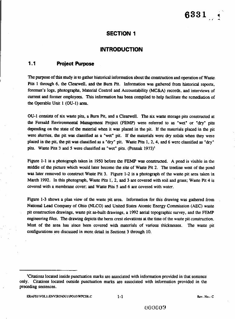
The purpose of this study is to gather historical information about the construction and operation of Waste Pits 1 through 6, the Clearwell, and the Bum Pit. Information was gathered from historical reports, foreman's logs, photographs, Material Control and Accountability (MC&A) records, and interviews of current and former employees. This information has been compiled to help facilitate the remediation of the Operable Unit 1 (OU-1) area.
OU-1 consists of six waste pits, a Burn Pit, and a Clearwell. The six waste storage pits constructed at the Fernald Environmental Management Project (FEMP) were referred to as "wet" or "dry" pits depending on the state of the material when it was placed in the pit. If the materials placed in the pit were slurries, the pit was classified as a "wet" pit. If the materials were dry solids when they were placed in the pit, the pit was classified as a "dry" pit. Waste Pits 1, 2.4, and 6 were classified as "dry" pits. Waste Pits 3 and 5 were classified as "wet" pits. (Pennak 1973)'
Figure 1-1 is a photograph taken in 1950 before the FEMP was constructed. A pond is visible in the middle of the picture which would later become the site of Waste Pit 2. The treeline west of the pond was later removed to construct Waste Pit 3. Figure 1-2 is a photograph of the waste pit area taken in March 1992. In this photograph, Waste Pits 1, 2, and 3 are covered with soil and grass; Waste Pit 4 is covered with a membrane cover; and Waste Pits 5 and 6 are covered with water.
Figure 1-3 shows a plan view of the waste pit area. Information for this drawing was gathered from National Lead Company of Ohio (NLCO) and United States Atomic Energy Commission (AEC) waste pit construction drawings, waste pit as-built drawings, a 1992 aerial topographic survey, and the FEMP engineering files. The drawing depicts the berm crest elevations at the time of the waste pit construction. Most of the area has since been covered with materials of various thicknesses. The waste pit conQurations are discussed in more detail in Sections 3 through 10.
'Citations located inside punctuation marks are associated with information provided in that sentence only. Citations located outside punctuation marks are associated with information provided in the preceding sentences.
ERAFSl\VOL1:ENVIRO\OU1\P010\WPCSR.C 1-1 Rev. No.: C

Figure 1-1 - Photograph dated 1950 - Pre-Construction
ERAFS 1 WOLl :ENVIRO\OU l\POlO\WPCSR.C 1-2 Rev. No.: C
003080

Figure 1-2 - Site Photograph from March 1992
ERAFS1\VOLl:ENVIRO\OU1\P010\WPCSR.C 1-3 Rev. No.: C
00001%

__ - I I 2 I 3 I 4 I I 6 I 7 I a
I I 2 I 3 I 4 I 5 I . 6 I
Figure 1-3 - Waste Pit Area Plan View
ERAFS l\VOLl :ENVIRO\OUl\POlO\WPCSR.C 1 4 Rev. NO.: C
WlES
. EXlSIIHG cwITlows wwn or THIS mvlffi MRE PREP~RED FRM FEW SITE ~ R O V I O E O w n FRM IK
FXISIIPG SITE onin Y~CRCE Pmsms 1 o p o r ~ ~ ~ i . 1 ~ FEW cam WIDIUIILITi W a U l N c S FEW CCNIRAEIOR PROJECl U S l G N W N Q H T S
*33 P W C U M N I S LISTED BELOW. (IN PLWT FIL
. TM G C M I R I C t O l C I ~ T I C N . t O Y E R lWICKNESS.BOTlOn ELEVIIIONS. CNl LOU PERHElBlLl I i MIERIm IHICYIESS W E E
FEnSIBILI I I STUDl lFSl OWWINGS IJANSRI 31.1W.RfV.ll. BORING LOCLaH) F R M I S EXISTING PLWT EPGIMTRINC FILES.
UIEFWNED FRO^ IS BEST n v n i L m E cwn nT IHIS 11%. IHIS cain uns n s s c n S L E n FROH CCNSIRUCIICN ns-wxi. WRVEV.
. IME DIM CREST aw ice E ~ E S YM( m a w THE wnsTE PIIS REFWESENT CWITIONS n i IK TIPS (F TS RESPECTIVE P I1 CMTFUCIICN. M N i CF I K S E DIKES CNl TW EDGES MVE BEEN COVEREO WITH MlERI&S (F DIFFERENT T W 1 0 3 Q S L
i TK ETF aw IESI PIT M L ~ G E R PRESENT m TIE wnsrE PITS.
LEGEN)
_ _ _ _ _ - - - --A
I NOT FOR CONSTRUCTION I
DEPARTMENT OF ENERGY FERNALD ENVIRONMENTAL MANAGEMENT PROJEC
1m c u n ~ PKP.CD II
rH RUM Y. PIRSOM co. - PARSONS CHIS. T. uw. NC. - MGB(EERX;-SCMQ. H
CINCINNATI. OHIO

6331 + - A . -
1.2 Plant History
The FEMP, formerly known as the Feed Materials Production Center (FMPC), was constructed and began operations in 195 1. The NLCO entered into a contract with the AEC , predecessor to the United States Department of Energy (DOE), as Operations and Maintenance (O&M) Contractor. On January 1, 1986, Westinghouse Environmental Management Company of Ohio (WEMCO), formerly known as Westinghouse Materials Company of Ohio (WMCO), took over the O&M contract. (DOE 1987) On October 1,1992, the Fernald Environmental Restoration Management Corporation (FERMCO) took over as the Environmental Restoration Management Contractor at the FEMP.
The FEMP originally produced metallic uranium fuel cores for the DOE'S production reactors. Later, as needs changed, the FEMP process was changed to produce uranium trioxide for the gaseous diffusion plants, depleted uranium metal fuel cores, and small quantities of low-enriched uranium ingots and thorium compounds. Figure 1-4 shows the production process at the FEMP and the major waste streams. (Pennak 1973)
From 1953 to 1955, the FEMP processed pitchblende ore from the Belgian Congo. In 1956, uranium concentrates (yellowcake) from Canada and the United States were processed. Canadian yellowcakes contained higher levels of thorium than the yellowcake from the United States. Canadian yellowcakes were not processed after 1960. From 1954 through 1975, small amounts of thorium were processed at theFEMP. (DOE 1987)
Ore concentrates, recycled uranium, and other various uranium compounds were received at Plant 1 (Sampling Plant) where the material was weighed and sampled for nuclear material accountability records. The feed material was then sent to Plant 2/3 (Refinery) where it was fed into tanks for digestion in nitric acid. The resulting slurry was sent through an extraction system to separate the uranyl nitrate (UNH) from the insoluble acid and excess nitric acid. The aqueous UNH was then sent through a denitration process (evaporation and heating) to obtain uranium trioxide (UO,) or orange oxide. Extraction raffinate and other low-level uranium wastes generated in Plant 2/3 were precipitated and neutralized with lime prior to discharge to settling ponds. The U03 was either shipped to the DOE gaseous diffusion plant at Paducah, Kentucky or it was sent to Plant 4 (Green Salt Plant), where it was converted to uranium dioxide (UO,) by reduction with hydrogen. The UOz was then converted to uranium tetrafluoride (UF,) or green salt, in a reaction with anhydrous hydrogen fluoride (AHF). The green salt was then transferred to Plant 5 (Metals Production Plant) where it was blended with magnesium granules and heated to produce uranium derbies.(WESTON 1986a)(NLO undated)(NLCO 1973)(Facemire et al. 1985)(DOE 1987)
ERAFS 1 \VOLl :ENVIRO\OU 1 \POlO\WPCSR.C 1-5
.- 0 0 0 0 13
Rev. No.: C

URANIUM REFINERY FEEDS, REMELT METAL 8 RESIDUES FROM OFF SITE
I
TO WET CHEMICAL WPSTE PIT
INDNIDLJAL PUNT SUMP DISCHARGES
TO MIAMI RIVER
TO WET CHEMICAL WASTE PIT .
*-.1.1.1..
I N b DlSSOClATOR
TAIL GAS i i ANHYDROUS HF + HF)
!
* ! !
I I I
(FORSALE) i ! i .I.I.I.I.I.I.-.-.I.l t
METAL REDUCTION
* LIMITED OPERATIONS
t UNDER PAST PRODUCTION PROGRAM
RESIDUES I METAL ROLLING p REMELT METAL
METAL MACHINING
+ FINISHED FUEL CORES & BILLETS TO REACTOR SITES
ERAFS2\MACDATA\IUUS\OU-l~l~EMP SCHEMATIC DWG
Figure 1 4 - Production Process
ERAFS1WOL1:ENVIRO\OU1\POlO\WPCSR.C 1-6 Rev. No.: C

6331. s. ,
Cleaned derbies were then placed in graphite crucibles with scrap uranium metal and heated to produce uranium ingots. Ingots destined for extrusion were sampled, cropped, and sent to Plant 6 (Metals Fabrication Plant) where they were heat-treated in a molten salt bath. Ingots were sent off-site for the extrusion process. The extruded tubes were returned to the FEMP in 10-foot lengths. In Plant 6, the extruded tubes were then cut into 8-inch lengths, heat treated, and machined to proper specifications. The finished tubes were cleaned, inspected, and packaged for shipment to other DOE facilities. (WESTON 1986a)(NLO undated)(NLCO 1973)(Facemire et al. 1985)@0E 1987)
Plant 8 (Recovery Plant) processed uranium recycle materials. Plant 9 (Special Products Plant) processed uranium metal pieces larger than those processed in Plants 5 and 6 as well as performjng the Zirnlo process, which was a decladding operation. Reject fuel elements were immersed in a solution of hydrofluoric acid to dissolve material that encased the uranium metal fuel element. The Pilot Plant most often handled enriched uranium feed materials containing up to 10 percent U-235. The Pilot Plant also occasionally processed thorium materials. (WESTON 1986a)(NLO undated)(NLCO 1973)(Facemire et al. 1985)(DOE 1987)
Thorium production steps are similar to those followed in the production of uranium. Final thorium products produced at the FEMP were acid solutions of thorium nitrate tetrahydrate, thorium hydroxide gel and powder, thorium tetrafluoride, solid thorium compounds, and thorium metal. (Boback et al. 1970)(NLCO 1973)
1.3 ' Liquid Wastes
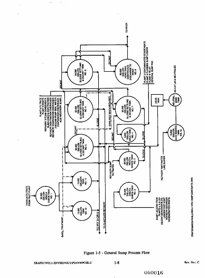
Each plant had its own wastewater treatment equipment for the collection and pretreatment of process water. The pretreatment was specific to each plant waste stream, but normally consisted of pH adjustment for precipitation of uranium and filtration of the resultant slurry. Filter cakes from each individual water treatment system were taken to the Refinery or the Recovery Plant as a process residue. Effluents from the plants were sampled and then pumped to the General Sump. The operation of the General Sump varied slightly over the years, but a simplified flow diagram of the primary process of the General Sump is shown in Figure 1-5. Thorium wastes were segregated, co-precipitated with barium carbonate and aluminum sulfate to reduce the activity of Ra-228, and then pumped to Waste Pit 5 . (Pennak 1973)
Uranium wastes were adjusted for pH with calcium oxide (CaO) to help precipitate the radioactive material. The activity of Ra-226 was then reduced by the addition of barium sulfate (BaSO,). The effluent, with a high content of suspended solids, was then discharged to Waste Pit 3 or, later on, Waste Pit 5 . From 1975 until 1984, filter cakes, from Plant 8, resulting from the filtration of neutralized raffinates and sludges accumulated in the General Sump tanks, and recycled slurries from Waste Pit 5 were classified as dry waste and deposited into Waste Pits 3 and 4 (Pennak 1975)(Pennak et al. 1976)(Pe~ak et al. 1977)(Diehl et al. 1984). In 1984, the filter cake was stored in drums and the solids-
ERAFS l\VOLl :ENVIRO\OU 1 \POlO\WPCSR.C 1-7 .. x , . ? ' , .
Rev. No.: C
003015
. . - .
a E W
U P
pp
I- d
3 W z
Figure 1-5 - General Sump Process Flow
ERAFS 1\VOL1 :ENVIRO\OU l\POlO\WPCSR.C 1-8 Rev. No.: C

free filtrate was pumped to Waste Pit 5 . Also, any sludges which settled in the General Sump were transferred to Waste Pit 5 . In the waste pits, the suspended solids in the water settled out and the clear supernatant liquid passed on to the Clearwell. The effluent was then combined with other plant effluents and sampled prior to discharge to the Great Miami River. (Diehl et al. 1984)(NLCO 1960)(NLCO 1973)
The majority of the liquid wastes were transported from the General Sump to the waste pit area through two 6-inch diameter pipes. The pipes travel from the production area toward the K-65 Silos through an enclosed, underground concrete trench backfilled with soil. The pipes extend west to the fence around the K-65 Silos where the pipes turn north. The two pipes branch at the waste pit area. One pipe rum north between Waste Pits 2 ,3 , and 4 to Waste Pit 5 and the second pipe runs west to the Clearwell. The pipe from the General Sump to Waste Pit 5 C O M ~ C ~ S to three berm valves on the southern berm of Waste Pit 5 . With these valves, the liquid waste could be directed from the General Sump to Waste Pit 4 or 5 , from the pits to the General Sump, or from one pit to the other pit. An additional pipe is routed from the effluent tower in the southwest end of Waste Pit 5 through the Waste Pit 3 berm to the Clearwell. Overflow from Waste Pit 5 traversed through this pipe to the Clearwell. The 6-inch pipe from the General Sump to the Clearwell was used to transport effluent from the Clearwell back to the General Sump. (WESTON 1986a)(DOE 1987)
I
1.4 Solid Wastes
Drummed solid wastes were transported to the waste pits on semi-flatbed trailers. Drummed pyrophoric metal was transported on four-wheeled flatbed trailers pulled by tow tractors. Solid waste contained in dumpsters were transported to the waste pits by dumpster vehicles. Bulk residues were transported to the waste pits by dump trucks and dump trailers. Once at the waste pits, the contents were emptied directly on the edge of the waste pit or on dumping pads. An industrial fork truck equipped with a drum rotator was used to empty drummed waste. The materials were then pushed into the pits by either a bulldozer or a drag line scraper. (NLCO 1977) Loose material was washed from the transport vehicles and the dumping pads into the pits (WESTON 1986a).
ERMS I\VOLI :ENVIRO\OU l\POlO\WPCSR.C 1-9 003087
Rev. No.: C

1.5 Common Waste Types
Listed below are the five most prevalent waste types and a brief description of each waste:
1) Magnesium fluoride (MgF,) slag and residue - white
2) Sump cake, filter cake, and trailer cake - course material with high moisture content, usually brown with yellow streaks, sometimes gray in appearance
3) General sludge - aqueous waste, similar to dirty water, water containing small particles, color was mid to dark brown, maroon, gray, or green
4) Dust collector residues
5 ) Scrap graphite - black, may be coated with light gray material. (interviews)
ERAF!3 1\VOL1 :ENVIRO\OU l\POlO\WPCSR.C 1-10 0OOGBc.I
Rev. No.: C

6331
2.1 Historical Documents
Documents were gathered from the F E W library, the Public Environmental Information Center (PEIC), the PARSONS library, and International Technology Corporation (IT). Information was also obtained from logs each foreman prepared to maintain a record of daily activities.
Section 11, References, lists all of the documents which have been used for this study. To help locate these documents the following system has been established:
1)
2)
3)
2.2
If the document has an FMPC or NLCO number at the end of the reference, it is located at the F E W Library by this number.
If the document has a number in brackets starting with a "G," a copy can be obtained from the PEIC using this number.
If the document has a number in brackets starting with a "P," it is in the PARSONS library.
Photographs
Photographs of the waste pit area from NLCO, the FERMCO photography laboratory, the PEIC, the DOE, and from Historical FMPC PhotoResearch ofNarionaf Archives (DOE 1991c) have been reviewed. A photograph database, using Base IV version 1.5 software, enables anyone to easily locate any photograph desired. The photographs are logged by date, visible pits, type of photograph (Le., aerial, oblique; aerial, direct; ground shot; or close-up), type of activity (construction, dumping, etc.), color versus black and white, negative location, negative number, volume, section, and remarks or notes. The database can be sorted on any field or searched for a particular entry in a specific field. An example report of a search for all aerial photographs showing the waste pit area is provided as Appendix A.
A print of each located picture of the waste pit area was obtained. These prints may be found in the Waste Pit Contents Study Photographs (PARSONS 1993b), which is a seven volume set. If a photograph is located using the database, the volume and section fields refer to the location in the Waste Pit Contents
Study Photographs (PARSONS 1993b).
ERAFS 1 \VOLl :ENVIRO\OU l\POlO\WPCSR.C 'I - , : ; a a - , , , . . i ; !
2- 1 Rev. No.: C

2.3 Material Control and Accountability Records
MC&A records were used to track the disposal of any waste material. The master file of these records was destroyed during a fire in the storage vault. (interviews) The MC&A Department conducted a search throughout site files and records for any existing copies of these records. Sequence numbers 100 through 247 and 87-1 through 87-5 were located. These records have been compiled into a database using dBm IV version 1.5 software. The database contains fields for the sequence number, date, drum lot number, percent uranium, percent U-235, laboratory number, number of containers, net weight, cubic feet, disposal pit, guess pit, and text fields for the material code, class code, and remarks. If the disposal pit was not indicated on the MC&A record, the field labelled guess pit is marked "yes" to indicate that the designated pit was determined by this report and not the MC&A record. When using the database, question marks may appear where numbers were not legible on the MC&A records.
The database can be sorted on any field or searched for a particular entry in a specific field. Two example reports are provided in Appendix B. The first report was a search for all contaminated asbestos material in Waste Pit 4. The second report was a search for all contaminated soil, rocks, sand, bricks, and ceramics material in Waste Pit 4.
2.4 Interviews
PARSONS has interviewed current and former FERMCO employees to gather historical information about the construction and operation of Waste Pits 1-6, the Clearwell, and the Burn Pit. As of July 1, 1993, PARSONS has interviewed the following FERMCO employees:
George Bassitt Charlie Block Dwayne Bonfor Lester Bunk Melvin (Doc) Cleeter Joe Patton Leroy (Digger) Pennington Glenn Rieman Ed Schonegg Lucy Rathgens
2-2 Rev. No.: C 003020

2.5
633 1 1-'
Volume Calculations
The volume of cover, waste, and low permeability material for each waste pit was calculated with the Integraph Corporation InRoadsMite version 4.01.01.00 software. The surface of each material was created by the surfacing modeling portion of the InRoads/InSite software. The surface modeling portion defines each surface by filling it with small triangular planes. The volumes are then calculated between any two surfaces. The triangles from one surface are projected onto the triangles on the other surface forming small prismoids that represent the volume between the two surfaces. The total volume is determined by summing the individual volumes of each prismoid formed by the corresponding pairs of triangles in any two surfaces. For example, the volume for the Waste Pit 3 cover was calculated from the triangulated surfaces from the existing surface and the surface of the existing waste.
ERAFSl\VOLl:ENVIRO\OUlWOlO\WPCSR.C . '
2-3
( b c i O G 2 1
Rev. No.: C
SECTION 3
WASTE PIT 1
3.1 Design and Construction
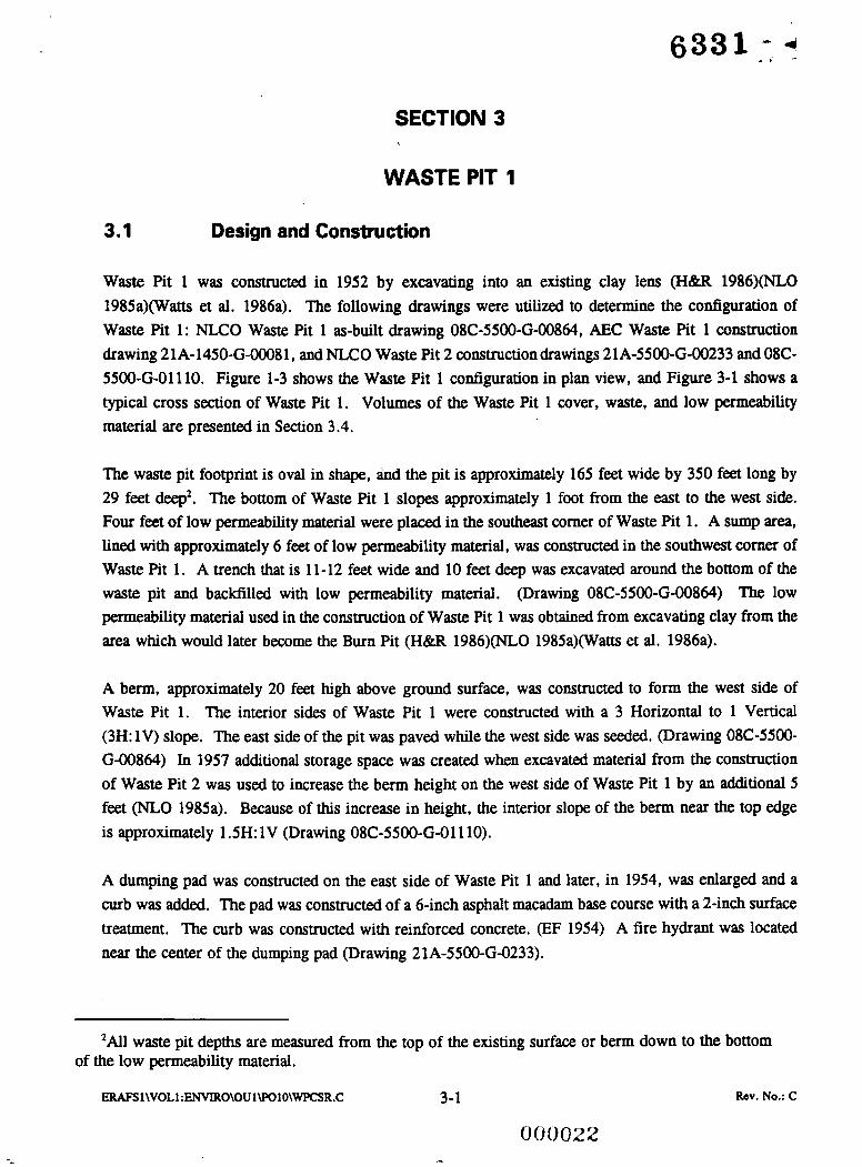
Waste Pit 1 was constructed in 1952 by excavating into an existing clay lens (H&R 1986)(NLO 1985a)(Watts et al. 1986a). The following drawings were utilized to determine the configuration of Waste Pit 1: NLCO Waste Pit 1 as-built drawing 08C-5500-6-00864, AEC Waste Pit 1 construction drawing 21A-1450-G-00081, and NLCO Waste Pit 2 constructiondrawings 21A-5500-G-00233 and OSC- 5500-G-01110. Figure 1-3 shows the Waste Pit 1 configuration in plan view, and Figure 3-1 shows a typical cross section of Waste Pit 1. Volumes of the Waste Pit 1 cover, waste, and low permeability material are presented in Section 3.4.
The waste pit footprint is oval in shape, and the pit is approximately 165 feet wide by 350 feet long by 29 feet deep2. The bottom of Waste Pit 1 slopes approximately 1 foot from the east to the west side. Four feet of low permeability material were placed in the southeast comer of Waste Pit 1. A sump area, lined with approximately 6 feet of low permeability material, was constructed in the southwest comer of Waste Pit 1. A trench that is 11-12 feet wide and 10 feet deep was excavated around the bottom of the waste pit and backfilled with low permeability material. (Drawing OK-5500-G-00864) The low permeability material used in the construction of Waste Pit 1 was obtained from excavating clay from the area which would later become the Bum Pit (H&R 1986)(NLO 1985a)(Watts et al. 1986a).
A berm, approximately 20 feet high above ground surface, was constructed to form the west side of Waste Pit 1. The interior sides of Waste Pit 1 were constructed with a 3 Horizontal to 1 Vertical (3H: 1V) slope. The east side of the pit was paved while the west side was seeded. (Drawing 08C-5500- G-00864) In 1957 additional storage space was created when excavated material from the construction of Waste Pit 2 was used to increase the berm height on the west side of Waste Pit 1 by an additional 5 feet (NLO 1985a). Because of this increase in height, the interior slope of the berm near the top edge is approximately 1.5H: 1V (Drawing 08C-5500-6-01110).
A dumping pad was constructed on the east side of Waste Pit 1 and later, in 1954, was enlarged and a curb was added. The pad was constructed of a 6-inch asphalt macadam base course with a 2-inch surface treatment. The curb was constructed with reinforced concrete. (EF 1954) A fire hydrant was located near the center of the dumping pad (Drawing 21A-5500-6-0233).
'All waste pit depths are measured from the top of the existing surface or berm down to the bottom of the low permeability material.
ERAFS 1 WOLl :ENWRO\OU 1 \Po lO\WPCSR.C 3-1 Rev. No.: C

I 2 I J I 4 I 5 I 6 1 7 I 0 I
E
6
-*. -
WEST
600
595
590
585
580
z 575
z 570 El ; 565
+
L L - >
560
555 SEE NOTE 2-
550
545
540
W
W4SlE PIT CONTENT STWV
W4SlE PIT CONTENT S T W V
- I - nul .o P1I
t a m m w IW - m a
E A S
SECTION a REF HORIZONTAL SCALE: 1.~60' GO1 VERTICAL SCALE: 1 . ~ 2 0 '
T
+ W W LL
Z - Z 2 t
> a W J W
s
I I 2 I 3 1 4 I 5 1 . 6 I . -
Figure 3-1 - Waste Pit 1 Cross Section I
ERAFSl\VOLl : WVIRO\OU l\POIO\WPCSR.C 3-2 RCV. No.: c
NOIES
1. TOP OF WASTE ASSUMED TO '
B E 6 ' F R O M E X I S T I N G GRADE.
2. APPROXIMATE LOCATION OF N A T I V E SOIL.
3. T H I S S U B M I T T A L SHOWS THE TO1 OF THE AOUIFER A S LOCATED 8' CERCLAIRCRA U N I T 5 (CRU-5). CRU-5 I S CURRENTLY UPDATING THE TOP OF THE AOUIFER MAP. ONCE THESE MAPS ARE UPDATED THEY WILL BE COMPARED WITH THE INFORMATION ORGINALLY PROVIOED BY CRU-5 AND ANY DISCREPANCIES WILL BE RESOLVED.
I cccm
LOW P E R M E A B I L I T Y M A T E R I A L (CLAY)
_ _ _ _ _ _ - _ _ _ LOW P E R M E A B I L I T Y - - - - - M A T E R I A L (NATIVE
M A T E R I A L ) - - - - -
TI SAND AND/OR GRAVEL
WASTE
IPRELIMINARY I I NOT FOR CONSTRUCTION I
DEPARTMENT OF ENERGY FERNALD ENVIRONMENTAL MANAGEMENT PROJEC
rnsmmcr*tr4Dn
PARSONS 1% R I L R ( Y PRSUiS CO. - ClUS 1. YrCcHc. - EMNEt3W.SCDIX.N
CINCINNATI. Onlo mctr li..:
SITE RESTORATION REPORT CRUllpol0 PI.Ic mu
WASTE PIT -1 SECTION
SK-6-01851 602 @
a
000023
Water drained from Waste Pit 1 through a series of three pipes located in the west berm (Drawing 21A- 5500-G-0233). Eight-inch decant lines were constructed through the west berm of Waste Pit 1 but were rarely used (NLO 1985a). In 1959, a channel at least 5 feet wide was maintained between the residues and the outer berm to permit the proper drainage of rainwater (Carvitti 1959). During 1958-1959, Waste Pit 1 was used as a clearwell for Waste Pit 2 (Watts et al. 1986a)(NLO 1985a). The solids would settle in Waste Pit 1, while the liquid would be discharged to the Great Miami River (EF 1958).
3.2 Operation
The majority of the materials placed in Waste Pit 1 were dry solids-including neutralized waste filter cakes, production plant sump cakes, depleted slag (magnesium fluoride), scrap graphite, contaminated brick, and sump liquor (Watts et al. 1986a)(H&R 1986)(WESTON 1986a)(NLO 1985a). The following materials were routinely dumped into Waste Pits 1, 2, or 3: trailer cake from Plant 8, neutralized filtrate from uranyl ammonium phosphate (UAP) cake from Plant 8 (including sump liquor), General Sump slurry from the Ore Refinery (including neutralized raffinates), broken graphite molds from Plant 5 , chemical feed sump residues from the Water and Boiler Plants, hand cleaned and moistened residues by the residue crew, and cooling water from heat treating operations in Plant 6. The feed sump residues from the Water and Boiler Plants and the cooling water from the heat treating operation were disposed of using a tank truck. The hand cleaned and monitored residues were disposed of with the use of a truck. Rainwater from the pipe trench in the K-65 area was pumped into the south end of Waste Pit 1 through an existing pump. (Carvitti 1959) Waste acid filter cake from Plant 8, depleted C-liner from the Storage Pad and Plant 5 , and sump cake from Plant 7 were disposed of in Waste Pit 1 (EF 1956). Figure 3-2 is a photograph of Waste Pits 1, 2, and 3, and the Clearwell dated August 1959. Part of Waste Pit 1 is covered, but drums are visible along the eastern edge of the pit. The open portion of Waste Pit 1 is full of water.
Water from the fire hydrant on the dumping pad was used to wash materials down into the pit (EF 1954). The transportation department was responsible for dumping materials in the waste pits and for maintaining the segregation of the materials, Waste Pits 1, 2, and 3 were divided into specialized dumping areas as shown in Figure 3-3, Waste Pit 1 was divided into the following four sections: depleted materials; filter (trailer) cakes from Plant 8; graphite from Plant 5 , bricks, stones, and miscellaneous solids; and chemical trap material or other miscellaneous drummed materials. (Carvitti 1959)
3.3 Interim Closure
Waste Pit 1 was closed and covered with clean fill soil in mid-1959 (NLCO 1977). In November 1972, soil was pushed from Waste Pits 1 and 2 into Waste Pit 3 as part of the Waste Pit 3 closure activities (EF 1972).
ERAFS l\VOLl: ENVIRO\OU 1 \Po lO\WPCSR.C 3-3
O c i O G 2 4 Rev. No.: C

Figure 3-2 - Photograph of Waste Pits 1, 2, and 3, and the Clearwell dated August 1959
Rev. No.: C ERAFS 1 WOLl :ENVIRO\OU 1WO IO\WPCSR.C 3-4
000025

AREA "G" RESERVED
P U N 50' 0 SO' 100'
Figure 3-3 - Waste Pits 1 , 2, and 3 Dumping Areas
3-5 ERAFS 1 \VOL 1 : ENVIRO\OU 1 \Po 10\WPCSR.C Rev. No.: C

Borings 1765, 1766, and 1767 taken during the Remedial InvestigationFeasibility Study (RIFS) activities indicate that Waste Pit 1 has waste material in the top 1 foot of cover material; therefore, PARSONS felt that the cover material should be included in the waste quantity. PARSONS was instructed by FERMCO to show 6 inches of cover material on drawings and in volume calculations (PARSONS 1993a).
MATERIAL DEPTH (Feet) I
3.4 Volume Calculations
VOLUME (Cubic Yards)
The following drawings were utilized to determine the configuration and volume of Waste Pit 1: NLCO Waste Pit 1 as-built drawing 08C-5500-6-00864, AEC Waste Pit 1 construction drawing 21A-1450-G- OOO81, and NLCO Waste Pit 2 construction drawings 21A-5500-G-00233 and 08C-5500-G-01110. The configuration of Waste Pit 1 is presented in Section 3.1. Material volume calculations were performed for Waste Pit 1 under PARSONS PO-88 Site Restoration Calculation Set 15-02. The results of the material volume calculations are shown in Table 3-1.
Cover
Table 3-1 - Waste Pit 1 Material Volumes
0.5 1,700
Low Permeability Material
TOTAL
11 18,200 (maximum)
29.5 (maximum) 68,400
Waste II 18 11 (maximum)
ERAFSl\VOLl :ENVIRO\OU l\POlO\WPCSR.C 3-6 oii0027 Rev. No.: C

SECTION 4
WASTE PIT 2
4.1 Design and Construction
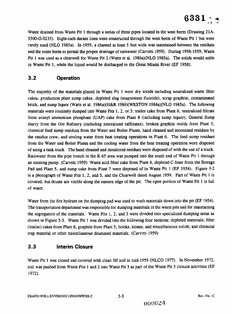
In 1957, Waste Pit 2 was constructed northeast of Waste Pit 1 (H&R 1986)(NLO 1985a)(WESTON 1986a). The following information was utilized to determine the configuration of Waste Pit 2: NLCO Waste Pit 2 construction drawing 21A-5500-G-0233, NLCO Waste Pit 4 drawing 08C-5500-G-01302, and RI/FS boring logs 1768 and 1769. Figure 1-3 shows the configuration of the pit in plan view, and Figure 4-1 shows a cross section of Waste Pit 2. The volumes of the Waste Pit 2 cover, waste, and low permeability material are presented in Section 4.5.
The Waste Pit 2 footprint resembles a six-sided polygon, and the pit is approximately 190 feet wide by 270 feet long by 23 feet deep (Drawing 21A-5500-G-00233). In the southern portion of the waste pit, a small, spring fed pond existed with a typical water elevation of approximately 574 feet. The pond was drained, and the pit was constructed by excavating a basin into the existing native clay (NLO 1985a). At the north end of the pit, trees, stumps and roots were removed from the bottom of the pit and the area was backfilled with clay to construct an impervious pit (EF 1956). The pit was lined with a compacted, on-site native clay layer (H&R 1986)(WESTON 1986a). The pit bottom and interior side slopes were lined with 4.5 feet of low permeability material (IT 1992). The low permeability material used in the construction of Waste Pit 2 was obtained by excavating material from the location of the future Burn Pit (H&R 1986)(NLO 1985a)Watts et al. 1986a).
The coordmates for the top edge of Waste Pit 2 were taken from construction drawing 21A-5500-G- 00233. These coordinates were checked against the survey coordinates shown for the northern edge of Waste Pit 2 on survey drawing 08C-5500-G-01302 for Waste Pit 4. The coordinates were very similar, and therefore, the coordinates given on the Waste Pit 2 construction drawing are assumed to be accurate. In addition, a revised Construction Proposal (EF 1956) dated November 13, 1956, stated that the new pit coordinates can be found on drawing 84069.
The construction drawing for Waste Pit 2, 21A-5500-G-00233, shows two 8-inch cast iron decant pipes constructed through the northwest berm of the waste pit. Like Waste Pit 1, the decant lines were rarely used (NLO 1985a).
Construction drawing 21A-5500-G-00233 indicates that a berm was constructed on the northwest side of the pit where a natural drainage flows. Although the Waste Pit 2 construction drawing showed the berm had a relative elevation of 98 feet, an approximate elevation was determined from the survey drawing of Waste Pit 4, 08C-5500-G-01302. The survey drawing indicates that the Waste Pit 2 edge has an
ERAFS 1 \VOLl:ENVIRO\OU l\POlO\WPCSR.C 4- 1 * - . Rev. No.: C
I I 2 I 3 I 4 I 5 I 6 1 7 I 8
I- W W LL
Z - Z
I-
>
E! a W -J W
NORTH WEST
SOUTH EAST
WASTE PIT ' 2
HORIZONTAL SCALE: 1.~60' . G01 VERTICAL SCALE: 1'=20'
I- W W LL
- I I I 2 I 3 I 4 I 5 I 6 I
Figure 4-1 - Waste Pit 2 Cross Section
ERAFS 1 \VOL1 :ENVIRO\OU l\POlO\WPCSR.C 4-2 Rev. NO.: C
I
MITES ~~
1. TOP OF WASTE ASS LEVEL WITH EDGE E 577+.
2. APPROXIMATE LOCATION OF NATIVE SOIL.
3. THIS SUBMITTAL SHOWS THE TOP OF THE AOUIFER AS LOCATED BY CERCLA/RCRA UNIT 5 (CRU-5). CRU-5 IS CURRENTLY UPDATING THE TOP OF THE AOUIFER MAP. ONCE THESE MAPS ARE UPDATED, THEY WILL BE COMPARED WITH THE INFORMATION ORGINALLY PROVIDED BY CRU-5 AND ANY DISCREPANCIES WILL BE RESOLVED.
LEGEMI
.\//\>( EXISTING SOIL El LOW PERMEABILITY F] MATERIAL ( C L A Y )
SAND AND/OR GRAVEL
I I WASTE
GBI I SITE PLm
I NOT FOR CONSTRUCTION I
t WASTE PIT CONTENT STWV
4 UnSTE PIT CONTENl STWV
n r s 10 DAn 6lu 01 m- MLB .uyIIIpI
UNITED STATES DEPARTMENT OF ENERGY
FERNALD ENVIRONMENTAL MANAGEMENT PROJECT INS mvnc ~ P - D or
PARSONS M RUFW Y. PIRMM C0.- W. 1. YbN. Nc. - EtGlKfERH;-SCENCE. NC
CMCINNATI. moa0 uy OHIO
SITE RESTORATION REPORT
m-.c n u cRuimie
WASTE PIT ' 2 SECTION
000029

approximate elevation of 576 feet Mean Sea Level. It is therefore assumed that the relative elevation of 98 feet is equivalent to 576 feet Mean Sea Level.
According to Waste Pit 2 construction drawing 21A-5500-6-00233, the existing road was built 4 feet from the edge of Waste Pit 2.
A change order dated May 20, 1957, indicated that the pit bottom was excavated to an elevation lower than the elevation shown on construction drawings. This change order was required because an impervious pit could not be obtained without further material removal and backfill with clay. (EF 1956)
The RI/FS boring logs 1768 and 1769 indicate that the top of the low permeability material for Waste Pit 2 is at an elevation of 561 feet. This elevation differs from the bottom elevation stated on the drawings in the Druff Feasibility Srudy Reporf for OU-1 - Task 12 (DOE 1991b) drawings and will be used as the bottom elevation.
4.2 Operation
Waste Pit 2 was primarily used as a dry pit, but some wet materials were placed in the pit before Waste Pit 3 was constructed (Pennak 1973). As shown on Figure 3-3, Waste Pit 2 was filled with semi-liquid, filter cakes, sump liquor, and other aqueous iiquids (Carvitti 1959). Waste Pit 2 received dry solids mainly consisting of neutralized waste filter cakes, sump cakes from the production plants, depleted slag, scrap graphite, contaminated brick, and sump liquor (Watts et al. 1986a)(NLO 1985a)(H&R 1986). The following materials were routinely dumped into Waste Pits 1, 2, or 3: trailer cake from Plant 8, neutralized filtrate from UAP cake from Plant 8 (including sump liquor), General Sump slurry from the Ore Refinery (including neutralized raffhates), broken graphite molds from Plant 5, chemical feed sump residues from the Water and Boiler Plants, hand cleaned and moistened residues by the residue crew, and cooling water from heat treating operations in Plant 6. The feed sump residues from the Water and Boiler Plants and the cooling water from the heat treating operation were disposed of using a tank truck. The hand cleaned and monitored residues were disposed of with the use of a truck. (Carvitti 1959)
In January 1958, Waste Pit 2 was filled with a "non-packing, soupy material" that was generated by the General Sump. The level of the waste pit rose about 6.5 feet (approximately 1.5 feet of slurry material and about 5 feet of liquid) since the previous October. The pit was expected to fill with waste from the General Sump within 6 months to a year. The Recovery Plant was not expected to start pumping their neutralized filtrate from the UAP cake until after February 1958. (Carvitti 1958)
From 1958 to 1959, Waste Pit 2 was used as a settling pond for neutralized raffkate residues. During this time, Waste Pit 1 was used as a clearwell for the effluent from Waste Pit 2. (Watts et al. 1986a)(NLO 1985a)
E M S l\VOLl :ENVIRO\OU l\POlO\WPCSR.C 4-3 Rev. No.: C

4.3 Test Pit on Top of Waste Pit 2
In 1975, a test pit for the above-grade storage of raffinate filter cake was constructed on Waste Pit 2. The test pit was 60 feet by 60 feet and was constructed of earth and coal cinders. The height of the test pit is unknown. An unloading area, about 20 feet in diameter, was constructed inside the test pit and roadfill gravel and sand were placed on the edge of the area. Raffhate cake from Plant 8 was dumped by truck into the unloading area, and the cake was moved into the southern half of the storage area with the use of a crane. From May 22 to June 9, 1975, 29 truckloads (275 tons) of filter cake were placed in the storage area. The filter cake was generated by the filtration of a lime neutralized raffinate stream and had a moisture content of about 70 percent. The filter cake was allowed to dry in the sun to remove some of the moisture to allow for a volume reduction. (Cavendish 1975) The mound was piled about 15 feet high. The height of the mound was reduced to about 6 to 8 feet after drying. The surface dried to a crust. This experiment was not considered a success. Material from this test was loaded into a truck with the use of a crane and then deposited into Waste Pit 3. (interviews)
4.4 Interim Closure
Waste Pit 2 was closed and covered with clean fill in mid 1964 (NLCO 1977)weston 1986a). In November 1972, soil was pushed from Waste Pits 1 and 2 into Waste Pit 3 as part of the Waste Pit 3 closure activities (EF 1972). It is assumed that the cover material varies from approximately 2 to 4 feet over the entire waste pit (PARSONS 1992a).
4.5 Volume Calculations
The following information was utilized to determine the configuration of Waste Pit 2: NLCO Waste Pit 2 construction drawing 21A-5500-G-0233, NLCO Waste Pit 4 drawing 08C-5500-G-01302, and RIFS boring logs 1768 and 1769. The configuration of Waste Pit 2 is presented in Section 4.1. Material volume calculations were performed for Waste Pit 2 under PARSONS PO-88 Site Restoration Calculation Set 15-03. The results of material volume calculations are presented in Table 4-1.
ERAFSl\VOLl :ENVIRO\OU l\POlO\WPCSR.C 4-4 000031 Rev. No.: C

6831 a
1 to 4
15 (maximum)
4.5
23.5 (maximum)
Table 4-1 - Waste Pit 2 Material Volumes
4,200
24,200
9,oOO
37,400
MATERIAL I1 DEPTH (Feet) I VOLUME (Cubic Yards) 11 Cover
Waste
Low Permeability Material
TOTAL
. W S 1\VOL1 :ENVIRO\OU l\WlO\WPCSR.C 4-5 Rev. No.: C

SECTION 5
WASTE PIT 3
5.1 Design and Construction
From 1958 to June of 1959, Waste Pit 3 was constructed by excavating into the underlying clay lens (H&R 1986)(WESTON 1986a). The following drawings were utilized to determine the configuration of Waste Pit 3: NLCO Drawing 21A-5500-G-00234 and NLCO Waste Pit 5 Construction Drawings 21X- 5500-G-00234/08X-550-G-01196 and OK-5500-S-01197. Figure 1-3 shows the Waste Pit 3 configuration in plan view, and Figure 5-1 shows a typical cross section of Waste Pit 3. The volumes of the Waste Pit 3 cover, waste, and low permeability material are presented in Section 5.4.
The pit resembles an irregular oval and is approximately 450 feet wide by 720 feet long by 42 feet deep (Drawing 21A-5500-G-00234). The configuration of the west and north side of Waste Pit 3 was determined from construction drawings and from the existing topography of the area. Waste Pit 3 was constructed by excavating into an existing low permeability material to an approximate elevation of 548 feet. Construction drawing 21X-5500-G-00234/08X-5500-S-01197 indicates that the west berm was constructed approximately 20 feet above the 1958 ground surface. The north side of Waste Pit 3 had no berm. The east side was formed from the west sides of Waste Pits 1 and 2. (Drawings 21X-5500-G- 00234/08X-5500-S-01197) The sides of Waste Pit 3 were constructed with a 1.5H: 1V interior slope and lined with 12 inches of clay (Drawings 2lX-5500-G-00234/08X-5500-G-O1196 and 08C-5500-S- 01197)(EF 1958). Some of the excavated soil was used to form the west wall of the pit. Layers of 6- to &inches were placed on the sides and compacted with a sheepsfoot roller. A natural layer of low permeability material forms the bottom of the pit. (NLCO 1977) Additional clay material was not placed in the bottom of the pit (Drawings 2IX-5500-G-00234/08X-5500-G-O1196)(EF 1958). Spoil areas for the construction of Waste Pit 3 were located due north of the pit and west of the pit; topsoil was placed further north of the pit. The spoil area due north of the pit was graded to an approximate elevation of 575 feet (Drawings 2lX-5500-G-00234/08X-5500-G-00196 and 08C-5500-S-01197).
To construct Waste Pit 3 and the Clearwell, a small creek which ran along the west embankment of Waste Pit 2 was relocated north of the existing Burn Pit, parallel to the railroad tracks (EF 1958). An effluent line from the General Sump was constructed through the north berm (Drawing 08-5500-P-01214). In 1965, the waste pit was expanded by adding 2 feet of additional material to the top of the berms (Watts et al. 1986a)(NLO 1985a). Since an updated as-built drawing could not be located, it is unknown if all of the berms were increased by 2 feet; therefore, this two foot increase is not shown on Figure 5-1. A 4 foot wide walkway was constructed of crushed stone on top of the berm between Waste Pit 3 and the Clearwell. In the middle of the berm, a weir was constructed to allow water to decant from Waste Pit 3 to the Clearwell. The weir was constructed on a 6-inch sand and gravel base. The base of the weir
ERAFS l\VOLl :ENVIRO\OU l\POlO\WPCSR.C 5-1 . Rev. No.: C
000033

- - I I I I I I I 8 I 2 3 4 5 6 7
k- W W LI
Z - a > W -1 W
NORTH WEST
SOUTH EAST
HORIZONTAL SCALE: 1'=60' G01 VERTICAL SCALE: 1.~20'
590
585
580
575
570
565
560
555
550
545
t W W LL
5
a > W _I W
I I 2 I 3 I 4 I 5 I 6 I
1. TOP OF WASTE ASSUMED TO BE
et53 PLE- LEVEL WITH DIK VATION 5752.
2. APPROXIMATE LOCATION OF NATIVE SOIL.
3. THIS SUBMITTAL SHOWS THE TOF OF THE AOUIFER AS LOCATED B'r CERCLA/RCRA UNIT 5 (CRU-5). CRU-5 IS CURRENTLY UPDATING THE TOP OF THE AOUIFER MAP. ONCE THESE MAPS ARE UPDATED, THEY WILL BE COMPARED WITH THE INFORMATION ORIGINALLY PROVIDED BY CRU-5 AND ANY DISCREPANCIES WILL BE RESOLVED.
LEGEN)
m] EXISTING SOIL
L O W PERMEABILITY E d MATERIAL (CLAY)
SAND AND/OR GRAVEL
1-1 WASTE
(PRELIMINARY1 I NOT FOR CONSTRUCTION I
B UASTE PI1 CONTENT STWY , UaSTE P I 1 CONTENT STWY
mars I ) 0.11 ssu 0. *1- - .-a# UNITED STATES
DEPARTMENT OF ENERGY
PARSONS re Rum u P- co. - aw T. um, HC. - wxEw.sma. M
SITE REsToRniioN W m R T cwvwie
FERNALD ENVIRONMENTAL MANAGEMENT PROJECl ins m a e o II
CINCINNATI. -0 *rc OHIO
m-wc 1 L N
WASTE PIT '3 SECTION
A 7 0 1 u85 1.1.1.1.1.11 I SK-G-01853 I G04 1 B
I 0 __ -
Figure 5-1 - Waste Pit 3 Cross Section
E M S l\VOLl :ENVIRO\OU l\POlO\WPCSR.C 5 -2 Rev. No.: C 000034

was 20 feet long by 19 feet wide and was constructed of reinforced concrete. The weir was constructed of 10-foot long, 4- by 8-inch boards stacked on top of each other. Additional 4 by 8 boards were added as necessary to increase the height of the weir. (Drawing 84152) In the early 1970s, the weir was removed, and the area was filled in with soil to create a wider berm between Waste Pit 3 and Clearwell (interviews).
5.2 Operation
From 1959 to 1968, Waste Pit 3 was operated as a wet pit for use as a settling basin (H&R 1986)(Watts et al. 1986a). Waste Pit 3 was divided into three sections (see Figure 3-3). In August 1959, only one third had been designated for use. This portion of Waste Pit 3 was designated to receive slurries from the Ore Refinery and the Recovery Plant. Material was not to be dumped here until Waste Pit 2 was filled. (Carvitti 1959) The majority of the wet material Waste Pit 3 received was lime-neutralized radioactive raffinate concentrate from Plant 8 and the General Sump (H&R 1986). The neutralized waste slurry was received through an inlet pipe at the north end of the pit. The solids settled in the pit, while the supernatant liquid flowed through weirs at the south end of the pit into the Clearwell. (NLCO 1977) Contaminated rainwater from the Bum Pit area was pumped into the north end of Waste Pit 3 with the use of a portable pump. The slumes from the Ore Refinery (Plant 2/3) and the Recovery Plant were pumped to Waste Pit 3. The solids settled out while the clear liquid passed over a weir to the Clearwell. (Carvitti 1959) In the late 1960s, an area was dug in the north end of the pit and wooden pallets were placed in this area and then crushed with the bulldozer (interviews).
The following materials were routinely dumped into Waste Pits 1, 2, or 3: trailer cake from Plant 8, neutralized filtrate from UAP cake from Plant 8 (including sump liquor), General Sump slurry from the Ore Refinery (including neutralized raffkates), broken graphite molds from Plant 5, chemical feed sump residues from the Water and Boiler Plants, hand cleaned and moistened residues by the residue crew, and cooling water from heat treating operations in Plant 6. The feed sump residues from the Water and Boiler Plants and the cooling water from the heat treating operation were disposed of using a tank truck. The hand cleaned and monitored residues were disposed of with the use of a truck. (Carvitti 1959)
5.3 Interim Closure
In 1970, when the pit could no longer be used as a settling basin, solid materials were placed in the pit starting from the northeast corner. A bulldozer was used to push flyash into the pit. While the bulldozer was on the pit surface, the flyash beneath the bulldozer dropped 7 or 8 feet as the underlaying materials moved under the load of the bulldozer. No damage resulted, and the bulldozer was easily retrieved. (Stevenson 1971)
ERAFS1 WOLl :ENVIRO\OU l\POlO\WPCSR.C 5-3 000035
Rev. No.: C

Prior to June 1, 1971, approximately 5,000 cubic yards of dry materials consisting of broken concrete and soil excavations from nearby areas were dumped into Waste Pit 3. Because of the hazards involved in placing these materials on the unstable sludge, it was decided to limit operations to the east side of the pit which was believed to be more stable. (Nelson 1972) In November 1972, a considerable amount of soil was pushed from Waste Pits 1 and 2 into Waste Pit 3. From June 1971 through December 1972 the engineering department kept records of how may truckloads of cinders from the south pit, silo cinders, dirt from the field, and coal fines from the coal storage area were placed in Waste Pit 3. The engineering department assumed that each truckload was equivalent to 10 cubic yards. Table 5-1 shows the amount of each material placed into Waste Pit 3 per month. (EF 1972) Figure 5-2 is a photograph taken in 1972 which shows the covering activities on Waste Pit 3.
From 1975 to 1977, slag leach residue, filter cakes, flyash, soil, and lime sludges were deposited into the pit (Watts et al. 1986a)(H&R 1986)(WESTON 1986a). From 1975 until 1984, some of the filter cakes, from Plant 8, resulting from the filtration of neutralized raffinates and sludges accumulated in the General Sump tanks, and recycled slurries from Waste Pit 5 were classified as dry waste and deposited into Waste Pit 3 (Pennak 1975)(Pennak et al. 1976)(Pennak et al. 1977)(Diehl et al. 1984). There was a road between Waste Pits 2 and 4 which was used to bring material to the pit by uuck. The waste would then be placed into the pit with the use of a bulldozer with a 15 foot extension. (interviews)
In 1975, when Waste Pit 3 was partially covered, the drainage patterns were changed to channel surface water from Waste Pits 1, 2, and 3 to the Clearwell and Waste Pit 4. The surface water from Waste Pit 4 was pumped into Waste Pit 5 to settle suspended solids. (Cavendish 1975)
In 1975,' a field demonstration was held on top of Waste Pit 3 to test the use of a drag scraper for dispersing raffinate and Waste Pit 5 sludge filter cake from a truck dumping point into the pit. The test proved this method was feasible, and the drag scraper was further used to prepare Waste Pit 3 for more filter cake dumping. (Ostendorf 1975)
In 1975, filter cake was put into Waste Pit 3 by using a transfer truck to dump the filter cake into a prepared depression on the edge of the pit. The solids were in a slurry form when first dumped but quickly came to rest. When the depression filled, a clam shell bucket scooped out the solids and piled them further into the pit. Often the solids would mound up to form a conical pile. (Patton 1975)
In 1975, Waste Pit 5 was almost full so several hundred thousand gallons of sludge were removed (Kispert 1978), combined with other waste streams, and pressed into filter cake (Pennak et al. 1976). The resulting filter cakes were primarily discarded into Waste Pit 3 (Pennak et al. 1976). When Waste Pit 5 was full and could not receive additional raffinate, the raffinate was filtered and the resultant filter cake was stored in an extension of Waste Pit 3 (Cavendish 1975).
Waste Pit 3 was closed and completely covered with clean fill in 1977 (H&R 1986)(WESTON 1986a).
ERAFS l\VOLl :ENVIRO\OU l\POIO\WPCSR.C 5-4 o(ioo36'
Rev. No.: C

Table 5-1 - Material Placed in Waste Pit 3 for Covering Purposes
The volume amount for this month does not include the fill from Waste Pits 1 and 2. 1
ERAFS I\VOLl :ENVIRO\OU l\POlO\WPCSR.C
\ * , .
5-5 000037
Rev. No.: C

Figure 5-2 - Photograph of Waste Pit 3 from 1972
ERAFSl \VOL1 : ENVIRO\OUl \POlO\WPCSR.C 5 -6 Rev. No.: C
000038

6831 i
MATERIAL
Cover
Waste
Low Permeability Material
TOTAL
5.4 Volume Calculations
DEPTH (Feet) VOLUME (Cubic Yards)
14 93,700 (maximum)
27 204,100 (maximum)
1 9,700
42 (maximum) 307,500
The following drawings were utilized to determine the configuration and volumes of Waste Pit 3: NLCO Drawing 2 1A-55O-G-00234 and NLCO Waste Pit 5 Construction Drawings 2 lX-5500-G-O0234/08X- 5500-G-01196 and 08C-5500-S-01197. The configuration of Waste Pit 3 is presented in Section 5.1. Material volume calculations were performed for Waste Pit 3 under PARSONS PO-88 Site Restoration Calculation Set 15-04. The results of material volume calculations are shown in Table 5-2.
Table 5-2 - Waste Pit 3 Material Volumes
PARSONS was instructed by FERMCO to place the bottom of the pit 1 foot above the top of the aquifer as defined by CERCLA/RCRA Unit 5 (CRU-5) (PARSONS 1993a). CRU-5 defined the aquifer under Waste Pit 3 to be at an approximate elevation of 547 feet. The bottom of the waste in Waste Pit 3 was located at an approximate elevation of 548 feet, therefore the low permeability material is assumed to be approximately 1 foot thick.
ERAFS I\VOLl:ENVIRO\OUl\POlO\WPCSR.C 5-7 Rev. No.: C

SECTION 6
WASTE PIT 4
6.1 Design and Construction
Waste Pit 4 was constructed in 1960. The configuration and elevations for Waste Pit 4 were taken from the following drawings: NLCO Waste Pit 4 construction drawings 08C-5500-G-01303 and 40A-1900-G- 00021; 1992 aerial topography; and N/FS boring logs 1773, 1774, and 1775. Figure 1-3 shows the Waste Pit 4 configuration in plan view and Figure 6-1 shows a typical cross section of Waste Pit 4. The volumes of the Waste Pit 4 cover, waste, and low permeability material are presented in Section 6.4.
The footprint of Waste Pit 4 resembles a trapezoid, and the pit is approximately 380 feet wide by 310 feet long by 32 feet deep (Drawing 21A-5500-G-00234). Waste Pit 4 was constructed with interior side slopes of 2H:lV (Drawing 40A-1900-G-00021). Waste Pit 4 was lined with 1 to 2 feet of low permeability material (Drawing 08C-5500-G-01303 and 08X-5500-G-01305).
The waste material is assumed to be present up to the top of the berm. The top of the berm is at an elevation of approximately 584 feet (Drawing 08C-5500-G-01303 and 08X-5500-G-01305). RI/FS borings logs 1773, 1774, and 1775 of Waste Pit 4 indicate that the bottom of the waste material is at an approximate elevation of 559 foot. Therefore, the waste depth is approximately 25 feet.
The thickness of the soil covers varies to allow for surface runoff. The maximum thickness of the cover is approximately 6 feet. (PARSONS 1992a)
6.2 Operation
Depleted uranium residues, low grade thorium residues, contaminated ceramics, and general refuse were discarded without treatment into Waste Pit 4. The depleted uranium residues (0.142 - 0.40 percent U- 235) were either not suitable for remelt or it was not economically feasible to recover the uranium. Thorium residues were placed in the pit when it was not economically feasible to reprocess the residues. The ceramics were from production electric furnaces. (Pennak 1973)(Battelle 1981) From 1975 until 1984, the majority of the filter cakes, from Plant 8, resulting from the filtration of neutralized raffinates and sludges accumulated in the General Sump tanks, and recycled slurries from Waste Pit 5 were classified as dry waste and deposited into Waste Pit 4 (Pennak 1975)(Pennak et al. 1976)(Pennak et al. 1977)(Diehl et al. 1984). Waste Pit 4 also received process residues, trailer cakes, slurries, raffinates, graphite, non-combustible trash, and asbestos (WESTON 1986a)(NLO 198%). Waste Pit 4 received construction rubble, crucibles, and contaminated asbestos (Castle 1985). Trash, cans, drums, graphite, graphite crucible molds (13 inches in diameter and 3 feet tall), solids abrasive materials, uranium metal,
ERAFSl\VOLl :ENVIRO\OU l\POlO\WPCSR.C 6- 1 Rev. No.: C
~ 0 0 0 ~ 0

I 2 I 3 I 4 1 5 1 6 I I
8
t- W W LL
Z +-.i
z
t-
> W
, - J : w
E a
WEST EAST
t- W W LL
t a > W 1 W
SECTION REF HORIZONTAL SCALE: 1.~60' [ G05) GQl VERTICAL SCALE: 1"=20' -
I I I I 1 I 2 3 4 5 6 I I
Figure 6-1 - Waste Pit 4 Cross Section
I 8
1. TOP OF WASTE LEVEL WITH DIKE CREST ELE- VATION 584%
2. THIS SUBMITTAL SHOWS THE TO OF THE AOUIFER AS LOCATED B CERCLA/RCRA UNIT 5 (CRU-5). CRU-5 IS CURRENTLY UPDATING THE TOP OF THE AOUIFER MAP. ONCE THESE MAPS ARE UPOATEC THEY WILL BE COMPARED WITH THE INFORMATION ORIGINALLY PROVIDED BY CRU-5 AND ANY DISCREPANCIES WILL BE RESOLVED.
m] EXISTING SOIL
LOW PERMEABILITY E] MATERIAL (CLAY)
SAND AND/OR GRAVEL
WASTE
. . . . .
IPRELIMINARY I I NOT FOR CONSTRUCTION I
I WASTE PIT CONTENT STWY
h W&TE PIT CONTENT SlWY
-4 uu.- m r s 10 DIN
Bu 01 *- -. -D
UNITED STATES DEPARTMENT OF ENERGY
PARSONS
XRNALD ENVIRONMENTAL MANAGEMENT PROJECl I- amc mrm 81
M R U R l U P M W S CO. - CHIS. 1. UUC. NC. - ENUMEW-SCLNCE, N CINCINNATI. -0 N-a Onlo
SITE RESTORATION REPORT cRUI/PoI0 DU..C n u
WASTE PIT .4 SECTION
- -
A
B
C
D
c
ERAFS 1 WOLl :ENVIRO\OU lW)IO\WPCSR.C 6-2 RCV. No.: C

magnesium fluoride, concrete, ceramics, drummed residues of uranium materials, pyrophoric chips and fines, concrete, thorium, and asbestos were deposited in Waste Pit 4. At least 100 drums were deposited on the west side of Waste Pit 4. (interviews) From 1980 to 1983, barium chloride was disposed of in Waste Pit 4 (WMCO 1989). Between May 1981 and April 1983, Waste Pit 4 received approximately 23,500 pounds of low-level radioactive waste containing barium chloride heat treatment salt (Watts et al. 1986a)(NLO 1985a).
Pyrophoric materials deposited in Waste Pits 4 and 6 were packaged in drums or cans no larger than 30 gallons. Drummed pyrophoric materials and dumpsters containing Plant 5 slag [magnesium fluoride (MgF,)] were transferred directly to the waste pit area. All other depleted residues were sent to Plant 1 first for sampling and analysis of total uranium and U-235. Non-pyrophoric material was stored in drums at the chemical pit storage pad and then discarded monthly. The majority of the time, the contents of the drum were emptied in the pit and the drum was returned to the production area for re-use. Special authorization was needed to discard the contents and the metal container into the pit. Pyrophoric materials and materials with sharp edges were discarded in Waste Pit 4 rather than Waste Pit 6 to protect the rubber liner in Waste Pit 6. (Diehl 1980) Lime was occasionally added to Waste Pit 4 to maintain a pH suitable for uranium precipitation (NLCO 1977).
The lids were only secured for transportation purposes and not for storage.
A concrete pad was located on the northeast edge of Waste Pit 4 which served as a temporary storage area for drummed material which was disposed of in the pit. A fire hydrant was located at the pad to wash down vehicles and materials on the pad. This wash water drained into the pit. (NLCO 1977)
In 1975, Waste Pit 5 was almost full so several hundred thousand gallons of sludge were removed (Kispert 1978), combined with other waste streams, and pressed into filter cake (Pennak et al. 1976). Some of the resulting filter cakes were discarded into Waste Pit 4 (Pennak et al. 1976).
During a site visit, Weston personnel observed a considerable quantity of construction rubble overlying miscellaneous material on Waste Pit 4 (WESTON 1986b). Miscellaneous materials may also be seen in the photographs of Waste Pit 4 taken in 1986 (PARSONS 1993b).
Water would periodically collect in Waste Pit 4, and the water would be pumped to the Clearwell overland through hoses (interviews).
During operation, Waste Pit 4 received approximately 23,900 pounds of trichloride salt consisting of 45 percent barium chloride, 32.5 percent potassium chloride, and 22.5 percent sodium chloride. Due to the barium content, Waste Pit 4 was classified as a Hazardous Waste Management Unit (HWMU) under the Resource Conservation and Recovery Act (RCRA). (Krauss 1988)
ERAFS l\VOLl :ENVIRO\OU l\POlO\WPCSR.C 6-3 Rev. No.: C

According to the MC&A records, the following five material types were deposited into Waste Pit 4 in the largest quantities:
1) Scrap salts, high fluoride, including floor sweepings 2) Incinerator cinders - material not passing through grate or screen 3) Dust collector residues - high fluoride 4) Wet sump or filter cake, non-oily and non-halide 5 ) MgF, for milling or discard.
Table 6-1 summarizes the MC&A records when either small quantities of materials were deposited more than 10 times or over 100 cubic feet of material was deposited into Waste Pit 4 (MC&A Database).
6.3 Interim Closure I
Disposal activities in Waste Pit 4 were terminated in 1985 (Krauss 1988), and Waste Pit 4 was closed in May 1986 (Weston 1986a). As an interim closure under RCRA, a cover was placed over Waste Pit 4 in 1989 (WMCO 1989). The cover was designed to prevent surface water infiltration. This cover involved placing subgrade fill into the existing pit surface to form a domed cap over the pit, covering the cap with approximately 2 feet of clay (bentonite) compacted to have a lo7 cm/sec permeability, and installing a 45 mil reinforced Hypalon cover over the clay. (Krauss 1988)
At the time of the pit’s closure, the surface of the pit was a shallow dome of soil surrounded by an earthen berm. The cover was designed to extend a minimum of 3 feet, and an average 9.8 feet, beyond the centerline of the earthen berm. The fill material was placed between the crown of the surface soil dome and the earthen berm. Approximately 5,000 cubic yards of fill material were required to provide sufficient slope to allow water to flow from the top of the dome outward in all directions, over the earthen berm, and into a newly excavated perimeter ditch. Soil and organic material excavated for the perimeter ditch were added to the fill material. (Krauss 1988)
Krauss stated that since heavy earth moving equipment was expected to generate dust and cause surface contaminants to become airborne, the construction contractor was prohibited from performing any excavation or regrading on the pit surface (Krauss 1988). Photographs from the covering activities on Waste Pit 4 show heavy earth moving equipment being used to regrade the pit surface (PARSONS 1993b). The cap was designed to place 0 to 3 feet of fill material over certain sections of the pit to minimize the addition of material while achieving the required slope (Krauss 1988).
The clay was combined with bentonite to achieve the required permeability. Approximately 7,000 cubic yards of clay was required to cover the pit to a depth of 2 feet while maintaining the necessary slope. (Krauss 1988)
ERAFS 1 \VOL 1 :ENVIRO\OU 1 \POlO\WPCSR.C 6-4 Rev. No.: C

6331
MATERIAL DESCRIPTION
Solid metal, other than cores, with embedded steel
Non-briquettable chips and turnings for oxidation
Contaminated asbestos material
Partially oxidized metal for sorting containing no METL-X
Table 6-1 - Summary of MC&A Records for Waste Pit 4
CUBIC FEET
6.22
14.39
65.30
76.80
Briquettable chips and turnings, high impur., for briquetting & double melting
Incinerator ashes - material passing through grate or screen
119.40
199.00
11 Mg oxide & Mg zirconate from crucible cleanout I 204.30
MgF, or CaF,, good liner material
Dust collector residues, high fluoride, > 20% assay
215.00
277.50
Contaminated soil, rocks, sand, bricks, and ceramics
Sludges, salt, soft, chloride (for Plant 8 recovery)
Contaminated Mg
331.85
395.20
453.00
Rockwell cleanings
Dirty prill, code 5 derbies, & Plant 1 titan mill clean-out, hi U
Contaminated rags, paper, and polyethylene
11 Dust collector residues, low fluoride I 1,209.70
458.70
534.90
561.00
Dust collector bags
Wet sump or filter cake, oil contd (abbreviation not defined)
Unfired reduction charges plus MgF, from liner cave-ins
Sludges, non-oily, for oxidation, including high or low free metal
ERAFS l\VOLl :ENVIRO\OUl W)lO\WPCSR.C 6-5
571.20
610.00
715.90
898.40
Rev. No.: C
Scrap U30s or Thoz, high fluoride
Furnace salt, solidified, chloride (for Plant 8 recovery)
Drum Decontamination residues, wet MgF,
1,673.60
1,703.30
1,795.90

,
Furnace salt, solidified, non-chloride
Scrap salts, high fluoride, including floor sweepings
Incinerator cinders - material not passing through grate or screen
Dust collector residues - high fluoride
Wet sump or filter cake, non-oily and non-halide
Table 6-1 - Summary of MC&A Records for Waste Pit 4 (Cont.)
2,850.30
3,274.40
3,672.80
3,937.90
8,168.90
MATERIAL DESCRIPTION I CUBICFEET
MgF, for milling or discard 9,122.80
6-6 0000.15
Rev. No.: C

The.Hypalon cover was placed over the pit in sheets that varied from 47.9 feet to 51.8 feet in length. An anchor system was designed to increase the cover’s stability during high winds. At every other seam, the sheets were joined together. One sheet’s edge was placed into a trench that was excavated 1 foot into the clay. The trench was backfilled with clay and compacted. The adjoining sheet was then welded, with adhesive, to the exposed surface of the buried sheet. On the perimeter of the pit, the cover was secured
. in a trench excavated to 4 feet, below the frost depth. Pillows, made of Hypalon and filled with sand, were welded to the cover surface at 50 feet intervals to act as weights. (Krauss 1988)
MATERIAL
Cover
Waste
Low Permeability Material
TOTAL
1.
A vent was installed through the Hypalon and clay to allow gas to escape. Rock channel protection was placed in the perimeter drainage ditch, and the exposed soil was seeded to prevent erosion. (Krauss 1988)
DEPTH (Feet) VOLUME MC&A VOLUME (Cubic Yards) (Cubic Yards)
6 14,600 N/A
25 55,100 N/A
1 3,100 NIA
32 72,800 346
6.4 Volume Calculations
The configuration, elevations, and volumes for Waste Pit 4 were taken from the following drawings: NLCO Waste Pit 4 construction drawings OK-5500-G-01303 and 40A-1900-G-00021; 1992 aerial topography; and RIFS boring logs 1773, 1774, and 1775. The configuration of Waste Pit 4 is presented in Section 6.1. Material volume calculations were performed for Waste Pit 4 under PARSONS PO-88 Site Restoration Calculation Set 15-05. The results of material volume calculations are shown in Table 6-2.
Table 6-2 - Waste Pit 4 Material Volumes
ERAFS I\VOLl:ENVIRO\OUI\POlO\WPCSR.C 6-7 Rev. No.: C

6331 -
SECTION 7
WASTE PIT 5
7.1 Design and Construction
Waste Pit 5 was constructed from July to October 1968 (NLO 1985a)(NLCO 1974)(Stevenson 1971). The following drawings were utilized in determining the configuration of Waste Pit 5 : NLCO Drawings 21X-5500-G-00196 and 21-5500-G-00197-0199. Figure 7-1 is a photograph dated November 1968 which shows Waste Pit 5 under construction. Waste Pit 5 was constructed by cut and fill, using the excavated material to .build a berm. Figure 1-3 shows the Waste Pit 5 configuration in plan view, and Figure 7-2 shows a typical cross section of Waste Pit 5 . The volumes of the Waste Pit 5 cover, waste, and low permeability material are presented in Section 7.6.
The footprint of Waste Pit 5 is rectangular in shape, and the pit is approximately 820 feet long by 240 feet wide by 30 feet deep. The pit extends about 15 feet above the original grade on the south side and 14 to 20 feet above grade on the north side. (Drawings 21X-5500-G-00196 and 21-5500-G-00197-00199) The pit was lined with a 60-mil thick Royal-Seal Ethylene Propylene Diene Monomer (EPDM) Elastomeric Membrane. (NLO 1985a)(H&R 1986)(WESTON 1986a) Seepage was encountered during excavation of the pit. The areas were seepage occurred, were overexcavated and filled with clay prior to installing the liner. (NLO 1985a)
The Engineering Files in the FEMP Computer Aided Drafting and Design Department contained a Construction Proposal for Waste Pit 5 . The coordinates that are shown on drawing 21X-5500-G-00196 locating Waste Pit 5 vary from the PARSONS 1992 topography by approximately 25 feet. Since Waste Pit 5 is an open pit and its berms and waste can be seen, PARSONS assumed that the 1992 topography governs the configuration.
A change order for the dredging of the Clearwell indicated that the construction contractor for Waste Pit 5 construction may have been Schweitzer Brothers Construction Company (EF 1968).
The bottom elevation of Waste Pit 5 is 560 feet at the east side and 558.5 feet at the west side. Waste Pit 5 was constructed with interior side slopes of 2.5H:lV. (21X-5500-G-00196) The top of the waste elevation is approximately 588 feet (PARSONS 1992a). Hence, the maximum depth of waste is approximately 30 feet.
During the construction of Waste Pit 5 , a soft spot was encountered on the southeast side of the pit. This area was over excavated to remove the mud. The area was then backfilled with clay. Perched water and rain runoff were encountered during excavation activities, but the majority of water in the pit was from
ERAFS 1\VOLI : ENVIRO\OU 1 \POlO\WPCSR.C 7- 1 oci\OG47
Rev. No.: C

Figure 7-1 - Photograph of the Construction of Waste Pit 5
ERAFS 1 \VOLl:ENVIRO\OU 1 \POlO\WPCSR.C 7-2
000048 Rev. No.: C

I 2 I 3 I 4 I 5 I 6 I I
t W W LL
Z .--. Z
b-
> W _J
W
2 a
I- W W LL
Z
z 0
- t-
> W _I W
a
SECTION f E l , REF HORIZONTAL SCALE: I m = 1 2 0 ' W GQl VERTICAL SCALE: 1 .~40 '
I 9 I 7 I I I 4 5 6 I Figure 7-2 - Waste Pit 5 Cross Section
7 I 0 IJJlES
1. E L E V A T I O N TOP OF WASTE 589%. ASSU wg&3 -
2. APPROXIMATE LOCATION OF N A T I V E SOIL.
3. T H I S S U B M I T T A L SHOWS THE TOF OF THE AOUIFER AS LOCATED B' CERCLA/RCRA UNIT ~ 5 p ( C ~ u - 5 ) . CRU-5 IS CURRENTLY UPDATING THE TOP OF THE AOUIFER MAP. ONCE THESE MAPS ARE UPDATED THEY WILL B E COMPARED WITH THE INFORMATION ORIGINALLY PROVIOED BY CRU-5 AND ANY DISCREPANCIES WILL B E RESOLVED.
LEGEND
,;,)P. '.;/ F] E X I S T I N G S O I L
LOW P E R M E A B I L I T Y MATERIAL (CLAY)
I I : . . 1 TI WASTE
SAND AND/OR GRAVEL
I NOT FOR CONSTRUCTION I
I l l B I W S l E PI7 CONTEM SlW1
DEPARTMENT OF ENERGY FERNALD ENVIRONMENTAL MANAGEMENT PROJEC
IWS m.n4 ram or
PARSONS IM Rum u. PIRMM co. - N. I. UIN.K. - m r m . s m a . r i
SITE RESTORATION REPORT cRuvmie
mrrc mu
WASTE PIT ' 5 SECTION
CINCINNATI. W O J u T N OHIO
ERAFSI\VOLI:ENVIRO\OUI\POIO\WPCSR.C 7-3 Rev. NO.: C

rain. The pit bottom was sloped from east to west to permit drainage for the construction and operation of Waste Pit 5. The perched water and rain water were pumped out of the pit from the west end. There was some discussion about bringing clay from Kentucky to line the pit bottom, but it was decided that it was not economically feasible and the pit bottom was not lined with Kentucky clay. (interviews)
The synthetic liner was manufactured, installed, and tested by UniRoyal, Inc. The liner panels were 20 feet by 100 feet by 1/16 inch thick. The panels were sealed together with 6-inch splices overlapped and adhered with a layer of adhesive, tiegum, and another layer of adhesive. Some problems were encountered with the splices sealing properly. The difficulties occurred primarily in the eastern end of the pit and the lower third of the panels. Celotex sheets were placed under the panels in the east end, and all of the defects were co~ected. (TIE 1987)
Two minor liner joint failures have been documented. One failure was at the intersection of the pit lining and the effluent tower. This failure was below the normal pool operating level. The second failure was at a membrane field splice near the feed end of the pit. This failure was above the normal pool operating level. Repairs were scheduled in December 1970. (NLCO 1970) It is unknown if these repairs were completed.
7.2 Operation
Waste Pit 5 was placed in service on October 21, 1968 (NLCO 1974)(Stevenson 1971). Liquid wastes from all of the plants were pretreated and then sent to the General Sump. At the General Sump, thorium wastes were co-precipitated with barium carbonate and aluminum sulfate, to reduce the activity of the Ra- 228, and then pumped to Waste Pit 5. Uranium wastes are treated at the General Sump with CaO to adjust the pH to obtain a maximum precipitation of the radioactive material and then pumped to Waste Pit 5. Any sludges which settled in the General Sump were also sent to Waste Pit 5 . All of the liquid waste entered Waste Pit 5 through a pipe in the eastern end of the basin. The uranium and thorium containing solids settled out and remained in the pit whle the supernatant liquor overflowed through an effluent tower in the southwest end of the pit where it subsequently flowed to the Clearwell. (Pennak 1973) Waste Pit 5 also received neutralized raffinate settled solids, slag leach slurry, sump slurries, and lime sludge from Plant 2/3 and Plant 8 (H&R 1986)(WESTON 1986a).
Slag leach slurry from Plant 2/3, heat-treat quench water from Plant 6, and Zirnlo slurry from Plant 9 were liquid wastes that directly discharged to Waste Pit 5 without first being treated at the General Sump (Pennak 1973).
Process wastewater effluents from thorium refining in the Pilot Plant were sent to the General Sump, where they were adjusted to a pH greater than 8, and a flocculating agent was added. After mixing, the treated wastewater was discharged to Waste Pit 5 for settling. (Boback et al. 1970)
W S 1 \VOL l:ENVIRO\OU lWlO\WPCSR.C 7 4 Rev. No.: C

In 1975, Waste Pit 5 was almost full. Several hundred thousand gallons of sludge were pumped from Waste Pit 5 to Plant 8 to try to extend the life of Waste Pit 5. The sludge was transferred to Plant 8 using a submersible pump mounted to a floating raft. (Kispert 1978) At Plant 8, the sludge was combined with other waste streams and pressed into a filter cake. The resulting filter cakes were primarily discarded into Waste Pit 3 with some also discarded into Waste Pit 4. (Pennak et al. 1976) When Waste Pit 5 was full and could not receive additional raffinate, the raffinate was filtered and the resultant filter cake was stored in an extension of Waste Pit 3 (Cavendish 1975).
7
Waste Pit 5 stopped receiving slurried materials in 1983. Waste Pit 5 stopped being used as a senling basin in 1987 (WMCO 1988). Waste Pit 5 is still covered with water.
7.3 Experimental Treatment Facility
In 1984, the Experimental Treatment Facility (ETF) was constructed for the purpose of volume reduction of the sludges that accumulated in Waste Pit 5. The ETF was constructed on the northwest corner of Waste Pit 3. The ETF was 20 feet by 48 feet, had a 6 foot high wood retaining wall, and was covered by a greenhouse-type enclosure. The original design included a sand and gravel filter bed underlain by a plastic liner. (WEMCO undated)
In November 1984, approximately 12,000 gallons of sludge was pumped from Waste Pit 5 to the ETF for dewatering. The accumulated liquids were subsequently pumped back to Waste Pit 5. On February 23, 1988, high winds removed the ETF roof. Removal Action (RA) 11 was initiated to alleviate the threat of release of the exposed dry sludges. (WEMCO undated) All of the material was removed from the ETF, and the ETF was dismantled by March 1992.
7.4 Liner Repairs
In the winter of 1990, the need for a maintenance action to repair the Waste Pit 5 liner was identified when rips and tears were observed in the liner during a visual inspection. The water in the pit was drained to the Clearwell, vegetation was removed from liner seams, and the waste material in the pit was pushed back to expose the liner seams below the level of the sludge surface. Each seam was inspected to determine what size patch, if any, was needed. The following three basic sizes of patches were used:
1 . Type A - 10 inches by 120 inches minor seam deterioration 2. Type B - 18 inches by 120 inches major seam deterioration 3. Type C - 48 inches by 120 inches major patch (old patch removed).
Repairs to the liner were made in accordance with the liner manufacturer’s repair instructions. Each seam repaired was washed, cleaned, and left to dry. The adhesive was brushed on the area to be patched
ERAFS 1 \VOLl: WVIRO\OU l\POlO\WPCSR.C 7-5 U O 3 0 5 1
Rev. No.: C

and left to dry (becoming tacky). The patch was installed over the repair area, smoothed out, and rolled out flat with a hand roller. After the patch was dry, a bead of caulking was installed around the entire perimeter of the patch. Each repair was visually inspected after installation. Approximately 95 seams were repaired. The Waste Pit 5 liner repair was completed on February 6, 1992. (PARSONS 1992b)
MATERIAL
Cover
-
7.5 Removal Action 18
DEPTH (Feet) VOLUME (Cubic Yards)
N/A N/A
In March 1992, Removal Action (RA) 18 was initiated to mitigate the threat of airborne releases of radioactive particles from the exposed surface of Waste Pit 5. The exposed material was moved from the shallow east end to the deeper west end of the pit to ensure that all the material would be covered with water. The waste material was moved with the use of a small pond dredge. (PARSONS 1992b) RA 18 was completed in December 1992.
Low Permeability Material
TOTAL
7.6 Volume Calculations
28 97,900
N/A N/A
303 97,900
The following drawings were utilized in determining the configuration of Waste Pit 5 : NLCO Drawings 21X-5500-G-00196 and 21-5500-G-00197-0199. The configuration of Waste Pit 5 is presented in Section 7.1. Material volume calculations were performed for Waste Pit 5 under PARSONS PO-88 Site Restoration Calculation Set 15-06. Calculated material volumes for Waste Pit 5 are shown in Table 7-1.
Table 7-1 - Waste Pit 5 Material Volumes
3This depth is measured from the top of the berm to the bottom of the liner.
ERAFSl\VOL1:ENVIRO\OUl\PO1O\WPCSR.C 7-6 Rev. No.: C

6331 ' * . .
SECTION 8
WASTE PIT 6
8.1 Design and Construction
Waste Pit 6 was constructed between September 1978 and June 1979 (NLO 1985a). The following drawings were utilized to determine the configuration of Waste Pit 6: NLCO Drawings 21A-5500-G- 00222 and 21A-5500-G-00225. Figure 1-3 shows the Waste Pit 6 configuration in plan view, and Figure 8-1 shows a typical cross section of Waste Pit 6. The volumes of the Waste Pit 6 cover, waste, and low permeability material are presented in Section 8.4.
Waste Pit 6 is square in shape with each side approximately 210 feet long and is approximately 24 feet deep. Waste Pit 6 was constructed in the same manner Waste Pit 5 was constructed and was also lined with a 60-mil EPDM liner (NLO 1985a). Construction drawings 21A-5500-G-00222 and 21A-5500-G- 00225 show a berm around all sides except the west side, which is adjacent to Waste Pit 4. The berm varies in height from approximately 4 to 8 feet. The bottom elevation of Waste Pit 6 is 560 feet (Drawing 21A-5500-(3-00222), and the elevation of the top of the waste is approximately 580 feet (PARSONS 1992b). Therefore, the depth of the waste material is approximately 20 feet.
Some of the Waste Pit 6 excavated material was used to widen the berm on the east side of Waste Pit 5 . A spoil area was formed to the east of Waste Pit 6. (Drawings 21A-5500-G-00222 and 21A-5500-G- 00225)
Seepage was encountered during excavation activities (NLO 1985a). According to the interviews, during the construction of Waste Pit 6, numerous pockets of groundwater were encountered. Great difficulties were encountered trying to keep the water pumped out of the pit. To eliminate liner buoyancy, holes were punched in the liner, a pump was inserted under the liner, and the groundwater was pumped out. Before cutting holes in the liner, extra pieces of rubber were fixed to the liner to prevent liner tears when the holes were cut. Sand bags were thrown in the bottom of the pit to keep the liner from floating. Because of the small pit size, the pit bottom was not pitched during construction. (interviews)
~
A concrete dumping pad was originally constructed on the west side of Waste Pit 6 (Drawing 21A-5500- G-00222). Later, a concrete dumping pad was constructed on the east side of the pit (interviews)(PARSONS 1992a).
ERAFS l\VOLl :ENVIRO\OU l\POlO\WPCSR.C 8- 1
009053
Rev. No.: C

I
miEs
1. TOP OF WASTE ASSUMED TO B f ' 2. APPROXIMATE LOCATION OF
ELEVATION 5802.
NATIVE SOIL.
t- W W LL
A
Z -
8
a II..
I-
> W _1 W
a
W S l E PIT CONTFN STWY
was- PIT CC~~TENT siwr I - mu L. m.60 -. -0l
585
580
575
570
565
560
555
550
545
540
nrr e D . 1 1
UNITED STATES DEPARTMENT OF ENERGY
PARSONS
SITE RESTORATION E m R T cRuI/rnie
FERNALD ENVIRONMENTAL MANAGEMENT PROJECT n6 Pul.G ram 01
IH RMRl U. PlAsars CO. - OUS. I. U W W. - CHWEERH;-XD(Ct Hc. CINCINNATI. Om0
-0 w
I*- n u
t- W W L L
E
-
z - z
+ > W _I W
El a
SECTION REF HORIZONTAL SCALE: 1'=60' Go1 VERTICAL SCALE: 1.~20'
I I 3 I 7 I I I 4 5 6 I Figure 8-1 - Waste Pit 6 Cross Section
CRU-5 I S CURRENTLY UPDATING THE TOP OF THE AOUIFER MAP. ONCE THESE MAPS ARE UPDATED, THEY WILL BE COMPARED WITH THE INFORMATION ORIGINALLY PROVIDED BY CRU-5 AND ANY DISCREPANCIES WILL BE RESOLVED.
I 3. THIS SUBMITTAL SHOWS THE TOP OF THE AOUIFER AS LOCATED BY CERCLAIRCRA UNIT ~ ~ - ( C R U - ~ ) . ~
-
B I FCFICI
[Zl 'Yb' EXISTING SOIL
t LOW PERMEABILITY l=j MATERIAL (CLAY) rl SAND AND/OR GRAVEL
1-1 WASTE
1 I D NOT FOR CONSTRUCTION
WASTE P I T .6 SECTION I F
ERAFS l\VOLl :ENVIRO\OU l\POlO\WPCSR.C 8-2 Rev. No.: C

8.2 Operation
Waste Pit 6 received non-coarse, non-pyrophoric solid wastes including depleted slag, green salt, filter cakes, and process residues (H&R 1986)(WESTON 1986a)(NLO 1985a). Pyrophoric materials were also deposited in Waste Pit 6 (DieN 1980). Excess rainwater that collected in Waste Pit 6 was pumped to Waste Pit 5 and then discharged to the Clearwell (H&R 1986)(WESTON 1986a)(NLO 1985a). Material was bulldozed or clam-shelled into the center of the pit (NLO 1985a). Extrusion residue, depleted sump filter cake from all of the plants, fine depleted slags, decladding "blue" water, and heat treated quench water were deposited into Waste Pit 6 (Diehl et al. 1984).
Pyrophoric materials deposited in Waste Pits 4 and 6 were packaged in drums or cans no larger than 30 gallons. The lids were only secured for transportation purposes and not for storage. Drummed pyrophoric materials and dumpsters containing Plant 5 slag (MgF,) were transferred directly to the waste pit area. All other depleted residues were sent to Plant 1 first for sampling and analysis of total uranium and U-235. Non-pyrophoric material was stored in drums at the chemical pit storage pad and then discarded monthly. The majority of the time, the contents of the drum were emptied into the pit, and the drum was returned to the production area for re-use. Special authorization was needed to discard the contents and the metal container into the pit. Pyrophoric materials and materials with sharp edges were discarded in Waste Pit 4 rather than Waste Pit 6 to protect the rubber liner. (Diehl 1980) Drums were not placed in pit due to the possibility of tearing the liner (interviews). In the early 198Os, bags of asbestos were placed in Waste Pit 6 (D. Carr).
Table 8-1 shows materials where according to the MC&A records, over 100 cubic feet of material were deposited into Waste Pit 6 (MC&A Database).
8.3 Removal Action 6
The use of Waste Pit 6 ceased as of March 11, 1985 (Castle 1985). In October 1990, RA 6 was initiated to move exposed materials in Waste Pit 6 below the waterline. The exposed material was moved to deeper parts of the pit with the use of a crane with a clamshell bucket. RA 6 was completed in December 1990. Photographs taken during RA 6 indicate the presence of green salt, yellow cake, and rubble (PARSONS 1993b).
ERAFS l\VOLl :ENVIRO\OU l\POlO\WPCSR.C 8-3 000055
Rev. No.: C

Table 8-1 - Summary of MC&A Records for Waste Pit 6
MATERIAL DESCRIPTION CUBIC FEET
11 Contaminated Merco-Dri and Hilco cake I 200.40
Wet sump or filter cake, oil contd
Sludges, salt, soft, chloride (for Plant 8 recovery)
Off-spec UF4 or ThF4
Dust collector residues, high fluoride, > 20% assay
11 Furnace salt, solidified, non-chloride I 252.00
345 S O
427.80
513.10
647.00
~~ ~ ~~~~
U308 rotexted Plant 8 furnace product
Mg oxide & Mg zirconate from crucible cleanout
Drum Decontamination residues, wet MgF,
Dust collector residues, low fluoride
1 290.10
1,167.00
1,5 12.90
2,113.30
~~
Incinerator ashes - material passing through grate or screen
Scrap U308 or Tho,, high fluoride
Wet sump or filter cake, non-oily and non-halide
Scrap salts, high fluoride, including floor sweepings
Dust collector residues - high fluoride
MgF, for milling or discard
I 324.00
3,127.40
8,154.90
8,221.44
11,634.20
24,593.30
ERAFS 1 \VOL 1 : ENVIRO\OU 1 \Po 1 O\WPCSR.C 8 4 0000554;
Rev. No.: C

633 1
MATERIAL
Cover
Waste
Low Permeability Material
TOTAL
1
8.4 Volume Calculations
DEPTH (Feet) VOLUME MC&A VOLUME (Cubic Yards) (Cubic Yards)
N/A N/A N/A
N/A
N/A NJA N/A
244 9,600 2374
20 9,600
The following drawings were utilized to determine the configuration and volumes of Waste Pit 6: NLCO Drawings 21A-5500-G-00222 and 21A-5500-G-00225. The configuration of Waste Pit 6 is presented in Section 8.1. Material volume calculations were performed for Waste Pit 6 under PARSONS PO-88 Site Restoration Calculation Set 15-07. Calculated material volumes from the construction of Waste Pit 6 are shown in Table 8-2.
Table 8-2 - Waste Pit 6 Material Volumes
‘This depth is measured from the top of the berm to the bottom of the liner.
ERAFS I\VOLI :ENVIRO\OU lWIO\WPCSR.C 8-5 Rev. No.: C
000057

SECTION 9
BURN PIT
9.1 Design and Construction
The Burn Pit was constructed in 1957 when the area was excavated to provide clay to line Waste Pits 1 and 2 (H&R 1986). The general area of the Burn Pit was taken from the Waste Pit 4 survey drawing, 08C-5500-G-01302. An approximate location of the Burn Pit is shown on Figure 1-3, and Figure 9-1 shows a typical cross section of the Burn Pit, Gravel was placed in the north end of the Burn Pit to permit truck traffic into the deepest part of the pit (interviews).
9.2 Operation
The Burn Pit was used to burn materials such as laboratory chemicals, combustible materials (including pyrophoric and reactive chemicals), oils, and low-level contaminated combustible material (H&R 1986). The Bum Pit was also used to burn cafeteria debris, cans, napkins, and skids when the Sewage Treatment Plant incinerator was inoperable (interviews). Figure 9-2 is a photograph of the Bum Pit dated August 1959. This photograph was taken looking south, and the weir between Waste Pit 3 and the Clearwell is visible in the upper right hand comer of the photograph. Burning debris is visible in the middle of the photograph.
9.3 Interim Closure
The northern end of the Burn Pit was filled in 1968 during the construction of Waste Pit 5 (interviews). The photographs show that part of the Burn Pit was still open in 1972 (PARSONS 1993b).
9.4 Volume Calculations
The configuration of the Burn Pit is presented in Section 9.1. Material volume calculations were performed for the Burn Pit under PARSONS PO-88 Site Restoration Calculation Set 15-08. Calculated material volumes from the construction of the Burn Pit are shown in Table 9-1.
ERAFS l\VOLl :ENVIRO\OU lWOlO\WPCSR.C 9- 1 Rev. No.: C 000058

NOES
n
NOTE: SINCE THE BURN PIT IS ASSUMED T T O BE LOCATED BETWEEN WASTE PIT 3
WSTE PIT CONTENT S T ~ Y I I
AND WASTE PIT 4. I T IS SHOWN WITH EAST COMMON BERMS TO THE WASTE PITS 7
WEST
595
590
585
~ 580
575
z 570 E 2 565
y 560
t-
LL - >
W Fi-c J 3 J
55e
545
c W W L L
Z - Z E: k
> W
a
J W
SECTION f H 7 REF HORIZONTAL SCALE: 1.~60' GO1 VERTICAL SCALE: 1520 '
I I 4 I 5 I 6 I Figure 9-1 - Bum Pit Cross Section
. THERE I S NO COVER ON THE BURN PIT, SOIL MIXED WIWASTE IS ASSUMED TO GO TO THE EXISTING GRADE.
!. APPROXIMATE LOCATION OF NATIVE SOIL.
3.THIS SUBMITTAL SHOWS THE TOP OF THE AOUIFER AS LOCATED BY CERCLAIRCRA UNIT 5 (CRU-5). CRU-5 IS CURRENTLY UPDATING THE TOP OF THE AOUIFER MAP. ONCE THESE MAPS ARE UPDATED. THEY WILL BE COMPARED WITH THE INFORMATION ORIGINALLY PROVIDED BY CRU-5 AND ANY DISCREPANCIES WILL BE RESOLVED.
LEGEH)
LOW PERMEABILITY MATERIAL ( C L A Y )
I I SAND AND/OR GRAVEL
SOIL MIXED WASTE
IPRELIMINARY I I NOT FOR CONSTRUCTION I
masc1 ul
SITE RESTORATION REPORT CRuI~P010
BURN PIT SECTION
ERAFSI\VOLI :ENVIRO\OU I\POIO\WPCSR.C 9-2 Rev. NO.: C
Figure 9-2 - Photograph of the Burn Pit dated August 1959
00006;~ E M S l\VOLl:ENVIRO\OU 1WO1 O\WPCSR.C 9-3 Rev. No.: C

683 1
MATERIAL DEPTH (Feet)
Table 9-1 - Burn Pit Material Volume
VOLUME (Cubic Yards)
NIA
26
NIA
26
Cover NIA
30,300
NIA
30,300
Waste
Low Permeability Material
TOTAL
RIFS boring logs 1776 and 1777 indcate debris, such as glass, ceramics, metal, wood, etc., exist at an approximate elevation of 558 feet. The photographs of the Burn Pit show waste along the sides of the Burn Pit (PARSONS 1993). PARSONS assumed that the Burn Pit sides have a 1H:lV slope to an approximate elevation of 558 feet.
PARSONS assumed that the area between Waste Pit 3 and Waste Pit 4 was the limit of the Bum Pit Area, as shown on Figure 1-3. A cover volume for the Burn Pit was not calculated because PARSONS assumed that the top of the Burn Pit area would be classified as waste.
ERAFS 1\VOL 1 :ENVIRO\OU 1 \POIO\WPCSR.C 9-4 009061
Rev. No.: C
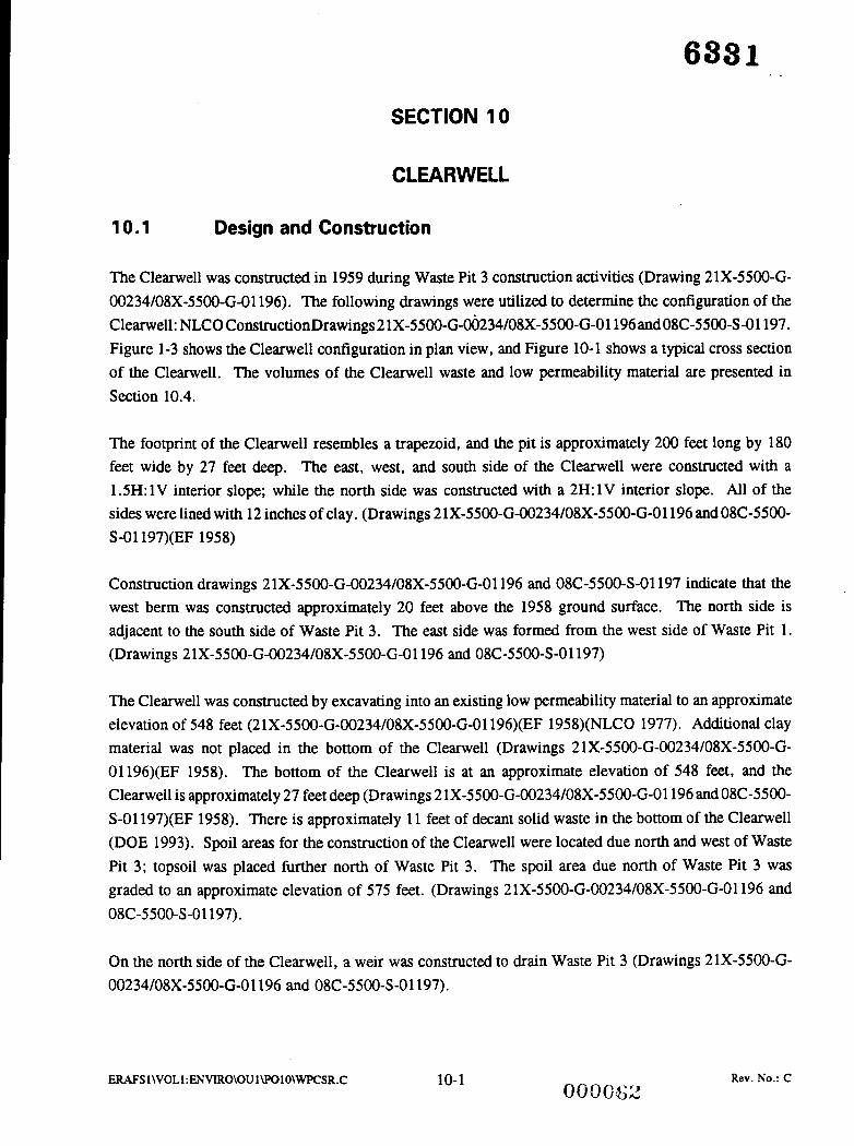
SECTION 10
CLEARWELL
10.1 Design and Construction
The Clearwell was constructed in 1959 during Waste Pit 3 construction activities (Drawing 21X-5500-G- 00234/08X-5500-G-O1196). The following drawings were utilized to determine the configuration of the Clearwell: NLCO ConstructionDrawings 21X-5500-G-~234/08X-5500-G-Ol196andO8C-55OO-S-O1197. Figure 1-3 shows the Clearwell configuration in plan view, and Figure 10-1 shows a typical cross section of the Clearwell. The volumes of the Clearwell waste and low permeability material are presented in Section 10.4.
The footprint of the Clearwell resembles a trapezoid, and the pit is approximately 200 feet long by 180 feet wide by 27 feet deep. The east, west, and south side of the Clearwell were constructed with a 1 SH: 1V interior slope; while the north side was constructed with a 2H: 1V interior slope. All of the sides were lined with 12 inches of clay. (Drawings 2lX-5500-G-00234/08X-5500-G-O1196 and 08C-5500- S-O1197)(EF 1958)
Construction drawings 21X-5500-G-00234/08X-5500-G-01196 and 08C-5500-S-01197 indicate that the west berm was constructed approximately 20 feet above the 1958 ground surface. The north side is adjacent to the south side of Waste Pit 3. The east side was formed from the west side of Waste Pit 1. (Drawings 2 lX-550O-G-00234/08X-5500-G-O1196 and 08C-5500-S-01197)
The Clearwell was constructed by excavating into an existing low permeability material to an approximate elevation of 548 feet (21X-5500-G-00234/08X-5500-G-O1196)(EF 1958)(NLCO 1977). Additional clay material was not placed in the bottom of the Clearwell (Drawings 21X-5500-G-00234/08X-55OO-G- 01196)(EF 1958). The bottom of the Clearwell is at an approximate elevation of 548 feet, and the Clearwell is approximately 27 feet deep (Drawings 2 lX-5500-G-00234/08X-5500-G-01196 and 08C-5500- S-O1197)(EF 1958). There is approximately 11 feet of decant solid waste in the bottom of the Clearwell (DOE 1993). Spoil areas for the construction of the Clearwell were located due north and west of Waste Pit 3; topsoil was placed further north of Waste Pit 3. The spoil area due north of Waste Pit 3 was graded to an approximate elevation of 575 feet. (Drawings 2 lX-5500-G-00234/08X-5500-G-01196 and 08C-5500-S-01197).
On the north side of the Clearwell, a weir was constructed to drain Waste Pit 3 (Drawings 21X-5500-G- 00234/08X-5500-G-01196 and 08C-5500-S-01197).
ERAFS l\VOLl:ENVIRO\OUl\PO1O\WPCSR.C 10-1 Rev. No.: C

I- W W LL
t, Z El c a > W J W
WEST EAST
575
570
565
560
555
550
545
540
SECTION REF HORIZONTAL SCALE: 1.~60' GQ1 VERTICAL SCALE: 1'=20'
575
570
565
560
555
550
i E I- a > W i W
I 5 I 4 I 5 I 6 I
Figure 10-1 - Clearwell Cross Section
MlES
. TOP OF WASTE ASSUMED TO BE
?. APPROXIMATE LOCATION ELEVATION 55%.
3. NATIVE THIS SUBMITTAL SOIL. SHOWS THE TOP OF THE AOUIFER AS LOCATED BY CERCLAIRCRA UNIT 5 (CRU-5). CRU-5 IS CURRENTLY UPDATING THE TOP OF THE AOUIFER MAP. ONCE THESE MAPS ARE UPDATED. THEY WILL BE COMPARED WITH THE INFORMATION ORIGINGALLY PROVIDED BY CRU-5 AND ANY DISCREPANCIES WILL BE RESOLVED.
LEGEN)
EXISTING SOIL
LOW PERMEABILITY [zd MATERIAL ( C L A Y )
1' ; . . . I .' . I SAND AND/OR GRAVEL
I I WASTE
I NOT FOR CONSTRUCTION I
3 WASTE PIT CONTENT S l l D Y
h W S T E PIT CONTENT STlDY
-I - .L nn *o -1,
EU 01 KSiX IIW. -0I
UNITED STATES DEPARTMENT OF ENERGY
PARSONS
FERNALD ENVIRONMENTAL MANAGEMENT PROJECl rm munc nnrc~ 81
IN RMW U. PMSRSONS CO. - MIS. 1. Nm. Hc. - ENCnrtERHC.XEtCE. M CINCINNATI. OHlO
-0 n u SITE RESTORATION REPORT cmmie
m-c mu
CLEARWELL SECTION
ERAFS 1 \VOLl :ENVIRO\OU 1 \POlO\WPCSR.C 10-2 Rev. No.: C

6331 A series of three pipes were located in the berm between Waste Pit 1 and the Clearwell (Drawing 21A- 5500-G-0233). Eight-inch decant lines were constructed through the berm between Waste Pit 1 and the Clearwell but were rarely used (NLO 1985a). Photographs taken during the dredging of the Clearwell indicate a pipe through the east side of the Clearwell (PARSONS 1993b).
To construct Waste Pit 3 and the Clearwell, a small creek which ran along the west embankment of Waste Pit 2 was relocated north of the existing Burn Pit, parallel to the railroad tracks (EF 1958).
10.2 Operation
The Clearwell received surface water runoff from all of the pits and liquid from Waste Pits 3 and 5 . The Clearwell is used as the final settling basin before water is discharged to the Great Miami River. (H&R 1986)(WESTON 1986a) In the late 1950s and early 1960s, water was periodically pumped from the Clearwell through the General Sump to the Great Miami River. During the early "wet" summer season when the river level was high, water could be syphoned or pumped over the weir from Waste Pit 3 to allow the maximum amount of liquid to be pumped to the Great Miami River. This would prevent Waste Pit 3 from overfilling during dry spells when water could not be pumped to the river because the volume of water in the river was too low to accept effluent concentrations from the Clearwell. Water pumped to the Great Miami River was sampled and analyzed daily. Water was allowed to be decanted or syphoned directly to Paddy's Run in an emergency during daylight hours only. (Carvitti 1959)
10.3 Dredging of the Clearwell
Figure 10-2 is a photograph of the Clearwell from November 1968. This photograph was taken from the northwest berm of the Clearwell looking east. (PARSONS 1993b) The Clearwell was dredged in the late 1960s or early 1970s (interviews)(EF 1968). It is suspected that Figure 10-2 is a photograph taken during the dredging activities. The sludge was pumped from the Clearwell to Waste Pit 3 (EF 1968). During the dredging activities, the water department became concerned with the pressure being applied to the north wall of the Clearwell from Waste Pit 3. Due to these concerns, the Clearwell was never emptied or dredged again. (interviews)
10.4 Volume Calculations
The following drawings were utilized to determine the configuration and volumes of the Clearwell: NLCO Construction Drawings 21X-5500-G-00234/08X-550O-G-O1196 and 08C-5500-S-01197. There is approximately 11 feet of waste in the bottom of the Clearwell (IT 1991). Material volume calculations were performed for the Clearwell under PARSONS PO-88 Site Restoration Set 15-04. Table 10-1 presents the calculated material volumes for the Clearwell.
ERAFSl\VOLl :ENVIRO\OU I\POlO\WPCSR.C 10-3 000064 Rev. No.: C

Figure 10-2 - Photograph of the Clearwell Dredging Activities
Rev. No.: C ERAFS 1 \VOL 1 : ENVIRO\OU 1 \Po1 O\WPCSR.C 10-4
000065

Table 10-1 - Clearwell Material Volumes
MATERIAL
Cover
Waste
Low Permeability Material
TOTAL
DEPTH (Feet) VOLUME (Cubic Yards)
NIA NIA
1 1 3,700
1 600
275 4,300
'This depth is measured from the top of the berm to the bottom of the low permeability material.
ERAFS 1 \VOLl :ENVIRO\OU 1 \POlO\WPCSR.C 10-5
00000;6
Rev. No.: C

6331 - 4 .
SECTION 11
SUMMARY
Table 11-1 presents a summary of the dimensions and volumes of various materials for each waste pit. Figure 11-1 presents a timeline of the OU-1 area showing construction periods, operation periods, closure periods, and other significant events.
ERAFSl \VOLl :Eh’VIRO\OU lWOlO\WPCSR.C 000067 11-1 Rev. No.: C

P: ENVIRO\OU 1 \PO 10\WPCSR.C
8 8 a z w m
4 6 z z
8 8 a g w m
b d z z
6 4 z z
o w N N
6 6 z z
z s x x
z 3 2 % N " x x
Y is
CP'
11-2
8 m d
- 8 W
8 rz m
- 6 z
Rev. No.: C

Waste Pit II
waste Pit 2
waste Pit 3
Waste Pi& 4
waste Pit 5
waste Pit 6
7/0/1193
'58 mid-59 '52
'57 mid-'64 z Test Pit Constructed
'58 6/59 70 '77
'60 5/86
10/68 11/84 '87
7/68 ETF Constructed
6/79 3/85
9/78
'72 '57
'89
12/90 * RA-6
'58 6/59 10168 &
Bedging
1'. i :N VII1O\OU IWOlO\WPCSR.C < ,
Figure 1 1-1 - OU-1 Timeline
11-3 Rev. No.: c

(AS1 1986)
6381 -
SECTION 12
REFERENCES
Advanced Sciences, Inc., October 1986. Workplan for the Remedial Investigation of the Feed 'Materials Production Center, Femald, Ohio. Volume 1: Background, Part 1: Evaluation of Current Situation, prepared for Westinghouse Materials Company of Ohio, Cincinnati, Ohio.
(Battelle 1981) Battelle Laboratories, Inc., 1981. Environmental Report of rhe Feed Materials Production Center. Columbus: Battelle Laboratories. [G-000- 106.47P-294.81
(Beers) Beers, H.M., undated. Operating Manual for Accountability in the Scrap Plant. Cincinnati: NLCO. FMPC-333 [P-2381
(Boback et al. 1970) Boback, M.W., J.O. Davis, K.N. Ross, and J.B. Stevenson, July 7, 1970. Disposal of Low-level Radioactive Wastes From Pilot Plant Operations. Cincinnati: NLCO. NLCO-1075.
(Boback et al. 1977) Boback, M.W., K.N. Ross, and D.A. Fuchs, April 1, 1977. Feed Materials Production Center Environmental Monitoring Annual Report for 1976. Cincinnati: NLCO. NLCO-1142.
(Boback et al. 1979) Boback, M.W. and K.N. Ross, May 1, 1979. Feed Materials Production Center Environmental Monitoring Annual Report for 1978. Cincinnati: NLCO. NLCO-1159.
(Boback et al. 1980) -----, May 1, 1980. Feed Materials Production Center E?ivironmenral Monitoring Annual Report for 1979. Cincinnati: NLCO. NLCO-1164.
(Boback et al. 1987) Boback, M.W., T.A. Dugan, D.A. Fleming, R.B. Grant, and R.W. Keys, May 1987. History of FMPC Radionuclide Discharges. Cincinnati: WMCO. Revision to FMPC-2058. FMPC-2082. [G-000-101.9/P-284.1]
(Breitenstein 1953) Breitenstein, J.S., ed., July 15, 1953. Summary Technical Report for rhe Period April I , 1953 to June 30, 1953. Cincinnati: NLCO. FMPC-255.
PENVIRO\OUl\POlO\WPCSR.C 12-1 Rev. No.: C
0000'10

(Carvitti 1958)
(Carvitti 1959)
(Castle' 1985)
(Cavendish 1975)
(Davis 1954)
(Diehl 1980)
(Diehl et al. 1984)
(DOE 1977)
(DOE 1985)
(DOE 1987)
(DOE 1990)
Carvitti, J.E., January 7, 1958. NLCO memo to M.S. Nelson. Subject: New Scrap Pit Investigation. NLCO.
Carvitti, J.E., August 1, 1959. Standard Operating Procedure for the Operation of the Chemical Pits. Revision 2. Cincinnati: NLCO. NLCO-694.
Castle, S.A., April 29, 1985. Feed Materials Production Center Radioactive Waste Management Plan. Revision 6. Cincinnati: NLO. NLCO-1100.
Cavendish, J. H., September 5, 1975. Environmental Assessment Above-Grade Storage of RaDnate Filter Cake. Cincinnati: NLCO. NLCO- 1 126. [G-000-107.1/P-287.4] .
Davis, J.O., ed., January 15, 1954. Summary Technical Report for the Period October I , I953 to December 31, 1953. Cincinnati: NLCO. FMPC-365.
----- , December 10, 1980. Standard Operating Procedure for On-site Shipment . and Discard of Depleted Uranium Metals. Revision 3. Cincinnati: NLO.
NLCO- 102 1.
Diehl, A.R. and T.A. Poff, March 19, 1984. Feed Materials Production Center Radioactive Waste Management Plan. Revision 5 . Cincinnati: NLO. NLCO- 1 100.
United States Department of Energy, 1977. Environmental Impact Assessment, Feed Materials Production Center. Cincinnati: DOE. NLCO-1148.
----- , 1985. Report on Historic Uranium Releasesfrom Current DOE Oak Ridge Operations ODce Facilities. Oak Ridge, Tennessee: DOE. [Updated - see (DOE 1988)]
----- , 1987. Remedial Investigation and Feasibility Study, Feed Materials Production Center, Fernald, Ohio, Task I Report: Description of Current Situation. Oak Ridge, Tennessee: DOE.
----- , December 1990. Remedial Investigation Report for OU-I - Task 6. Oak Ridge Operations Office: DOE. FMPC-0106-3. [P-2101
P:ENVIRO\OU l\POlO\WPCSR.C 12-2 Rev; No.: C
638 1
(DOE 1991a) -__-- , January 4, 1991. Initial Screening of Alternatives for OU-I - Task 12. Oak Ridge Operations Office: DOE. FMPC-0112-6. [P-211.11
(DOE 1991b) --_-- , April 1991. Draft Feasibility Study Report for OU-1 Task 15. Oak Ridge Operations Office: DOE. FMPC-0115-3. [P-211.21
(DOE 1991c) ---__ , August 1991. Historical FMPC Photo Research of National Archives. DOE Fernald Site: WEMCO.
(EF 1954) Engineering File maintained by the FEMP CADD Department, August 11, 1954. Engineering file located under contract proposal CP-F-54-79.
(EF 1956) Engineering File maintained by the FEMP CADD Department, May 28, 1956. Engineering file located under contract proposal CP-F-56-24.
(EF 1958) Engineering File maintained by the FEMP CADD Department, July 11, 1958. Engineering file located under contract proposal CP-58-40.
(EF 1968) Engineering File maintained by the FEMP CADD Department, March 22, 1968. Engineering file located under contract proposal CP-68- 13.
(EF 1972) Engineering File maintained by the FEMP CADD Department, November 2, 1972. Engineering file located under contract proposal CP-58-40.
(Facemire et al. 1985) Facemire, C.F., P.L. Jones, and R.W. Keys, July 15, 1985. Feed Materials Production Center Environmental Monitoring Annual Report for 1984. Cincinnati: NLO. NLCO-2028.
(H&R 1986) H&R Technical Associates, Inc., April 28, 1986. Feed Materials Production Center Installation Assessment. Oak Ridge, Tennessee: H&R Technical Associates, Inc. FMPC-2049. [P-297.491
(IT 1990) International Technology Corporation, July 25, 1990. Calculations. Subject: Pit # 5 Backfill. IT: Knoxville, TN.
P:ENVIRO\OUl \POIO\WCSR.C
. * :.. , . . . , , ' , :.( i
12-3 000072
Rev. No.: C

(IT 1991)
(IT 1992)
(Kispert 1978)
(Krauss 1988)
(Levy et al. 1965)
(Nelson 1972)
(NLCO 1960)
(NLCO 1966)
(NLCO 1970)
(NLCO 1973)
(NLCO 1974)
--__- , January 18, 1991. Calculations. Subject: Fernald Operable Unit #I Waste Pit # 1 Tables, Volume vs. Depth. IT: Knoxville, TN. Project Number 303317.
----_ , March 10, 1992. Calculations. Subject: Fernald Pit Volume Calculation. IT: Knoxville, TN. Project Number 313327.
Kispert, R.C., January 1978. Recovery of Uraniumfrom Pit Sludges and Cold Metal Oxide. Cincinnati:NLCO. NLCO-1149.
Krauss, Mark J. , September 1988. Interim Covering of Waste Pit 4 at the Feed Materials Production Center. Cincinnati: WMCO. FMPC-2 140.
Levy, L.M., A.R. Diehl, G.P. Miller, L. Williams and R.B. Wolf, June 17, 1965. Standard Operating Procedure for Operating the General Sump. Cincinnati: NLCO. NLCO-949.
Nelson, M.S., March 8, 1972. Letter form M.S. Nelson to C.L. Karl.
----- , November 22, 1960. Feed Materials Production Center Environmental Monitoring Quarterly Report for July, August, September 1960. [G-000-106.41
National Lead Company of Ohio, July 1966. Feed Materials Production Center Environmental Monitoring Semi-Annual Report for the First Half of 1966. Cincinnati: NLCO. NLCO-981. [G-000-106.181
----- , December 4, 1970. An OutlineDescription of the Construction of Chemical Waste Pit No. 5. Cincinnati: NLCO.
----- , February 16, 1973. Feed Materials Production Center Environmental Monitoring Annual Report for 1972. Cincinnati: NLCO. NLCO-1098. [G-000- 106.291
----- , October 24, 1974. Environmental Assessment Wet Chemical Waste Pit No. 6. Cincinnati: NLCO. NLCO-1112. [P-2 12. lo]
P:ENVIRO\OU l\POlO\WPCSR.C 12-4 000073
Rev. No.: C

683 1 (NLCO 1975)
(NLCO 1977)
(NLO undated)
(NLO 1981)
(NLO 1985a)
(NLO 1985b)
(Ostendorf 1975)
(ORAU 1985)
(PARSONS 1992a)
(PARSONS 1992b)
(PARSONS 1993a)
(PARSONS 1993b)
----- , November 1 1, 1975. Environmental Assessment of the Processing of Reactor Recycle Materials Containing Transuranium Elements. Cincinnati: NLCO. NLCO-1130. [G-OOO-lO7.2/P-287.3]
----- , April 25, 1977. Study of Radioactive Waste Storage Areas at the FMPC. Cincinnati: NLCO. NLCO-1143. [G-000- 10 1.283/P-2 12.91
National Lead of Ohio, Inc., undated. Uranium Feed Materials Production Center. [P-280.51
_---- , June 1981. Nuclear Materials Control and Accountability Plan. Revision 1. Cincinnati: NLO. NLCO-1173.
----- , March 12, 1985. Letter from T.A. Poff to W.J. Grannen, Re: Feed Materials Production Center Waste Inventory Data. Cincinnati: NLO.
----- , 1985. Unpublished Description of Waste Storage Facilities, contract with Roy F. Weston, Inc., West Chester, Pennsylvania.
Ostendorf, C.W., June 17, 1975. Letter to A.F. Pennak. Subject: Drag Scraper Demonstration: Engineering Project No. G-644, Filter Cake Disposal. NLCO.
Oak Ridge Associated Universities, October 1985. Environmental Program Review of the Feed Materials Production Center, Fernald, Ohio. Oak Ridge Tennessee. [G-000- 106.48/P-205.2]
PARSONS, 1992. Aerial topography.
PARSONS, July 1992. Control Exposed Material in Waste Pit 5 Removal Action 18 Work Plan. Cincinnati: PARSONS.
PARSONS, April 5, 1993. Meeting Minutes from March 25, 1993.
PARSONS, July 1993. Waste Pit Contents Study Photographs. Cincinnati, Ohio: PARSONS.
Rev. No.: C P: ENVIRO\OU 1 \PO 1 O\WPCSR.C 12-5 0000’74

(Patton 1975) Patton, J.B., March 14, 1975. Memo to N.R. Leist. Subject: Pit 5 Sludge/Raffinate Filter Cake Angle of Repose. NLCO.
(Pennak .1973) Pennak, A.F., June 20, 1973. Feed Materials Production Center Radioactive Waste Management Plan. Cincinnati: NLCO. NLCO- 1 100.
(Pennak 1974) Pennak, A.F., June 17, 1974. Feed Materials Production Center Radioactive Waste Management Plan. Revision 1. Cincinnati: NLCO. NLCO-1100.
(Pennak 1975) Pennak, A.F., June 16, 1975. Feed Materials Production Center Radioactive Waste Management Plan. Revision 2. Cincinnati: NLCO. NLCO-1100.
(Pennak et al. 1976) Pennak, A.F. and R.G. Lenyk, June 30, 1976. Feed Materials Production Center Radioactive Waste Management Plan. Revision 3. Cincinnati: NLCO. NLCO-1100.
(Pennak et al. 1977) Pennak, A.F. and R.G. Lenyk, July 31, 1977. Feed Materials Production Center Radioactive Waste Management Plan. Revision 4. Cincinnati: NLCO. NLCO-1100.
(Runion 1952) Runion, T.C., September 15, 1952. Summary Technical Report for the Period July 1, 1951 to September 30, 1952. Cincinnati: NLCO. FMPC-73.
(Runion 1953) ----- , April 15, 1953. Summary Technical Report for the Period January 1, 1953 to March 31, 1953. Cincinnati: NLCO. FMPC-183.
(RunionIWiding 1953) Runion, T.C. and R.A. Widing, February 1, 1953. Summary Technical Report for the Period October 1, 1952 to December 31, 1952. Cincinnati: NLCO. FMPC-210.
(Simmons 1954a) Simmons, J.W., ed., April 15, 1954. Summary Technical Report for the Period January 1, 1954 to March 31, 1954 Volume 1. Cincinnati: NLCO. FMPC-404.
(Simmons 1954b) ----- , October 15, 1954. Summary Technical Report for the Period January 1, 1954 to September 30, 1954. Cincinnati: NLCO. FMPC-475.
(Stevenson 197 1) Stevenson, J.B., February 1, 1971. A Study to Determine a Method for Filling Chemical Waste Pit Number 3. Cincinnati: NLCO.
P:ENVIRO\OU 1 \POlO\WPCSR.C 12-6 Rev. No.: C

683 1
(TIE 1987) Technical Information Exchange, April 21, 1987.
(Watts et al. 1986a) Watts, R.E., T. Allen, S.A. Castle, J.P. Hopper and R.L. Oelrich, October 15, 1986. Feed Materials Production Center Waste Management Plan. Cincinnati: WMCO. FMPC-2040.
(Watts et al. 1986b) Watts, R.E., T. Allen, S.A. Castle, J.P. Hopper and R.L. Oelrich, December 3 1, 1986. Feed Materials Production Center Waste Management Plan. Revision 1. Cincinnati: WMCO. FMPC-2040.
(WEMCO undated) Westinghouse Environmental Management Company of Ohio, undated. Pit 5 Experimental Treatment Facility (ETF) Removal Action Work Plan. Cincinnati: WEMCO.
(Weston 1986a) Weston, Roy F., August 1986, Site Characterization of the Waste Storage Areas, Part I : Evaluation of Current Situation, United States Department of Energy Feed Materials Production Center, Fernald, Ohio. [U-003- 101.17/P-2 10.51
(Weston 1986b) ----- , August 1986. Site Characterization of the Waste Storage Areas, Part 2, d Volumes 1 and 2: Support Documentation.
[U-003-101.19 and U-003-101.16/P-210.5]
(Weston 1987a) ----_ , October 1987. Characterization Investigation Study - Volume I: Geophysical Survey. West Chester, Pennsylvania: Roy F. Weston, Inc. [P-130.13
(Weston 1987b) ----- , November 1987. Characterization Investigation Study - Volume 2: Chemical and Radiological Analyses of the Waste Storage Pits. West Chester, Pennsylvania: Roy F. Weston, Inc. [P-130.11
(Weston 1987c) ----_ , December 1987. Characterization Investigation Study - Volume 3: Radiological Survey of Suqace Soils. West Chester, Pennsylvania: Roy F. Weston, Inc. [P-130.11
P:ENVIRO\OU 1 \POlO\WF'CSR.C
., - .. .:.: { ! '
12-7 0000%
Rev. No.: C

(Weston 1988) -----, March 1988, Characterization Investigation Study - Geotechnical Evaluation of Waste Pit Material Properties and Boring Logs. Albuquerque: Roy F. Weston, Inc. [p- 1 30.21
(WMCO 1988) ----_ , April 30, 1988. Feed Materials Production Center Environmental Monitoring Annual Report for 1987. Cincinnati: WMCO. FMPC-2 135.
(WMCO 1989) ----- , June 1989. Feed Materials Production Center Environmental Monitoring Annual Report for 1988. Cincinnati: WMCO. FMPC-2173.
P:ENVIRO\OU 1 \PO lO\WPCSR.C 12-8 Rev. No.: C
EXAMPLE OF PHOTOGRAPH DATABASE
APPENDIX A
PEh'VIRO\OU l\POlO\WPCSR.C
.:. \ r , .. .,... . . . '
Rev. No.: C

Page No. 1
Aerial Photographs of the Waste Pits and Surrounding Area
.-. 07/12/93
I1 I I (1 11 Photograph I Pit 1 1 Pit 2 I Pit 3 I Pit 4 I Pit 5 I Pit 6 I Burn Pit I Clearwell I Negative I Negative (1 11 Date I Y/N I Y / N I Y / N I Y / N 1 Y / N I Y / N 1 Y / N I Y / N I Number I Location 11
I I I I I I 1 I
11 01/01/50 I I I I I I I I I I I ,
I 3846-2 I FERMCO 11 II I( 01/01/50 I I I I I I I I
I I I I I I I I I I I I I I I I I I I I H
I 3846-3 I FERMCO II I I I I I I I
11 01/01/50 I I I I I I I I I I,
I 3846-4 1 FERMCO 1 I1 11 01/01/50 I I I I I I I I I1
I I I I I I I I I I I I I I I I I I I I B
I I I I I I I I I I H ' I 3846-5 1 FERMCO fl
I I I I I I I I I I
11 10/13/50 I I I I I I I I I 3719-6 I FERMCO t]
I I , , I I
11 12/13/51 I I I I I I I I I 5329-1 I FERMCO I II I I I I I I I I I I
I I I I I I I I I I n 11 12/13/51 I I I I I 1 I I I 5329-2 I FERMCO 11
I 1 I I I I
12/13/51 1 I I I I I I I I 5329-3 I FERMCO I I1 I I I I I I I I I 4
11 I I I I I 1 I I I I R 11 01/01/53 I Y I I I I I I I It I I I I I I I I I I H
I1 I I I I I I I I I 11
II I I I I 1 I I I I I il 11 08/01/57 I I I I I I I I I 35-37-1 I NLO H II I I I I I I I I I I u 11 05/26/61 I Y I Y I Y I Y I I I Y I Y I 1053-2 I NLO U It I I I I I I I I I B 1 1 05/26/61 I Y I Y I Y I Y I I I Y I Y 1 1053-3 I NLO II I1 I I I I I I I I fI 11 05/26/61 I Y I Y I Y I Y I I I Y I Y I 1053-4 I NLO 1 I1 I I I I I I I I 4 11 05/26/61 I Y I Y I Y I Y I I I Y I Y I 1053-5 I NLO II I1 I I I I I I I I I I B 11 05/26/61 I Y I Y I Y I Y I I 1 Y 1 Y I 1053-6 I NLO I II I I I I I I I I I 1 4
II 11 05/26/61 I Y I Y I Y I Y I I II I I I I I I I I I I f l 11 11/29/63 I Y I Y I Y I Y I I I Y I Y I 1424-1 I NLO I I1 I I I I I I I I I I Ii 11 11/29/63 I Y I Y I Y I Y I I I Y I Y 1 1424-2 I NLO n I1 I I I I I I I I I I U 11 11/29/63 I Y I Y I Y 1 Y I I I Y I Y I 1424-3 I NLO n It I I I I I I I I I i 11 11/29/63 I Y I Y I Y I Y 1 I I Y I Y I 1424-4 I NLO U II I I I I I I I I I I m 11 11/29/63 I I I I Y I I I I 1 1424-5 I NLO f
I I I I I I I I I I
11 01/01/52 I Y 1 I I I I I I I 3959-2 I FERMCO 11 I I I I I I I I I I
I 3846-1 I FERMCO I I I I I I I I I I
11 04/01/57 I Y I Y I I I I I Y I I DOE-I 1 FERMCO 11 I I I I I I I I I I
11 04/01/57 I Y I Y I I I I I Y I I DOE-J I FERMCO 1 I I I I I I I I I I
I I I I I I I I I I
I I I I I I I I I I
I I I I I I 1 I I I
I I I I I I I I I I
I I I I I I I I I I
I I I I I I I I I I
I Y I Y I 1053-7 I NLO I I I I I I I I I I
I I I I I I I I I I
I I I I I I I I I I
I I I I I I I I I I
I I I I I I I I I I

Page No. 2
Aerial Photographs of the Waste Pits and Surrounding Area
07/12/93
I1 I I I
11 Photograph I Pit 1 1 Pit 2 I Pit 3 I Pit 4 I Pit 5 I Pit 6 I Burn Pit 1 C l e a r w e l l I Negative I Negative 11 Date I Y/N I Y/N I Y/N I Y/N I Y/N 1 Y/N I Y/N I Y/N I Number I Location
II
II
I I I I I I 1 I I I I I I I I I I I I I
11 11/29/63 I I I I Y I I I I I 1424-6 I NLO I I I I I I I I I I I I I I I I I I I I
I FERMCO 11 11/01/72 I Y I Y I Y I Y I Y I I Y I Y I 3518-2
I
I FERMCO I 3518-5
11 I I I I 1 I I I , 11 11/01/72 1 Y I Y I y I y 1 y I I Y I Y I 4289-5 I FERMCO
II II 11/01/72 I y I Y I y I y I y I
I I 1 I I I I I I I I 1 I I I I I I I I
I y I Y I 4302-10 I FERMCO
I 1 I I I 1 1 I I I I I
I y I Y I 4302-11 I FERMCO II 11/01/72 I Y I y I y I I I I1 11 11/01/72 I I I Y l Y l Y l I Y I
I I I I I I I I I I I I I I I I I I I I
I 4302-11A I FERMCO
I 1 I I 1- - 1 ~~~ I-- 1 I I I 1
I Y 1 Y I 4302-12 I FERMCO 11 11/01/72 I Y I Y I Y I I I I1 I I I I I I I I I I
I I I I I I I I I I
11 11/01/72 I l Y l Y l Y l Y l I Y I I DOE-K I FERMCO
I 3457-1 I FERMCO
II I I I I I I I I I I I I I I I I I I I I
11 06/01/79 I I Y I Y I Y I Y I Y I y I I 3518-1 I FERMCO
I1 I I I I I I I $ I I
11 0 7 / 1 0 / 8 4 1 Y I Y I Y I Y I Y I Y I Y I Y 13602-1 I FERMCO
It 11 10/25/85 I Y I Y I Y I I II
II 11 10/25/85 I I I y I y / y / y I Y I II
I1
II
I I I I I I I I I I I I I I I I I I I I
I I I Y I 3652-1 I FERMCO I I I I I I I I I I I I I I I I I I I 1
11 10/25/85 I Y I Y I Y I I I I I Y I 3652-2 I FERMCO I I I I I I I I I I I I I I I I I I I I
I FERMCO I 3652-3 I I I I I I I I I I I I I I I I I I I
11 08/08/66 I l Y l Y l Y l Y l Y l y I I 3702-17 I FERMCO I I I 1 I I I I I I I I I I I I I I I I
11 08/08/66 I I I I Y l Y l Y l I I 3702-18 I FERMCO I I I I I I I I I I I I I I I I I I I I
11 08/08/86 I Y I Y I Y I Y 1 Y I Y I Y I Y I 3702-19 I FERMCO

Page No. 3
Aerial Photographs of the Waste Pits and Surrounding Area
I1 I I I 11
11 Photograph I Pit 1 1 Pit 2 I Pit 3 I Pit 4 I Pit 5 I Pit 6 I Burn Pit I Clearwell I Negative I Negative 11 11 Date I Y/N I Y/N I Y/N I Y/N I Y/N I Y/N 1 Y/N I Y/N I Number I Location 11
I I I I I I I I I I I1 I I I I I I I I I I II
It I I I I I I I I I I II
I1 I I I I I I I I I I iI
11 08/08/86 I Y I Y 1 Y I Y I Y I Y I Y I Y I 3702-2 I FERMCO 11 I I I I I I I I I I
11 08/08/86 I I l Y l Y l Y l Y l I I 3702-21 I FERMCO 11 I I I I I I I I 1 I
11 08/08/86 I I Y I Y I Y I Y I Y I y I 1 3702-26 I FERMCO II I1 I I I I I I I 4 I
11 08/08/86 I Y I Y I Y I I I I I Y I 3702-3 I FERMCO (1 I I I I I I I I I I It I I I I I I I I I I II
11 08/08/86 I Y I Y I Y I Y I Y I Y I Y I Y I 3702-6 I FERMCO 11
I 1 I 1 I I I I I I I
11 10/14/87 I Y I Y I Y I Y I Y I Y I Y I Y I 3896-109 I FERMCO 11 I I I I I I I I I 1 II I I I I I I I I I I II
It 1 I I I I I I I I I II
I1 I I I I I I I I I I ]I
II I I I I I I I I I II
II I I I I I I I I I I II
II I I I I I I I I I II
I1 I I I I I I I I I I I1
I 1 I I I I I I I I I I /I
I1 I I I I I I 1 I I I II
I 1 I I I I I I I I I II
I1 I I I I I I I I I I II
It I I I I I I I I I II
I1 I I I I I I I I I I II
I1 I I I I I I I I I I II
II 4
It II
11 10/14/87 I Y I Y I Y I Y I Y I Y I Y I Y I 3896-113 I FERMCO 11 I I I I I I I I I I
11 10/14/87 I I I I Y l Y l Y l I I 3896-115 I FERMCO 11 I I I I I I I I I I
11 10/14/87 I Y I Y I Y I Y I Y I Y I Y I Y I 3896-116 I FERMCO 1) I I I I I I I I I I
11 10/14/87 I I Y I Y I Y I Y I Y I y I I 3896-117 1 FERMCO 11 I I I I I I I I I I
11 10/14/87 I Y I Y 1 Y I I Y I I I Y I 3896-118 I FERMCO 11 I I I I I I I I I I
11 10/14/87 I I Y I Y I Y I Y I Y I y I I 3896-119 I FERMCO 11 I I I I I I I I I I
11 10/14/87 I I I Y l Y l Y l Y l Y I I 3896-12 I FERMCO 11 I I I I I I I I I I
11 10/14/87 1 l Y l Y l Y l Y l Y l y I I 3896-120 I FERMCO (1 I I I I I I I I I I
11 10/14/87 I l Y l Y l Y l Y l Y l y I I 3896-121 I FERMCO 11 I I I I I I I 1 I I
1) 10/14/87 I I I Y l Y l Y l Y l Y I I 3896-122 I FERMCO 11 I I 1 I I I I I I I
11 10/14/87 1 I I Y I Y I Y I Y I Y I I 3896-123 I FERMCO 11 I I 1 I I I I I I I
11 10/14/87 I Y 1 Y I Y I Y I I I I Y I 3896-129 I FERMCO 11 I I I I I I I I I I
11 10/14/87 I Y I Y I Y I Y I Y I Y I Y I Y I 3896-13 I FERMCO 11 I I I I I I I I I I
11 10/14/87 I Y I Y I Y I Y I Y I Y I Y I Y I 3896-28 I FERMCO 11 I I I I I I I I 1 I I I I I I I I I I I
I I I I I I I I I I I I I I I I I I I
11 10/14/87 I Y I Y I Y I Y I Y I Y I Y I I 3896-33 I FERMCO 11
11 10/14/87 I I Y l Y l Y I Y I Y I y I I 3896-35 I FERMCO 11

Page No. 4
Aerial Photographs of the Waste Pits and Surrounding Area
0 7 / 1 2 / 9 3
[I 1 I I I
11 Photograph I Pit 1 1 Pit 2 I Pit 3 I Pit 4 1 Pit 5 I Pit 6 I Burn Pit I Clearwell I Negative I Negativ Ii Date I Y/N I -Y/N I Y/N I Y/N I Y/N I Y/N I Y/N I Y/N 1 Number I Locatio
II 11 1 0 / 1 4 / 8 7 I I I I Y I Y I Y I I II
I I I I I I I I t I I I I I I I I I I I
I 3 8 9 6 - 3 8 I FERMCO I I I I I I I I I I I I I I I I I I I I
11 1 0 / 1 4 / 8 7 I Y I Y I Y I Y I Y I Y I Y I Y I 3 8 9 6 - 5 I FERMCO
I
I 3 8 9 6 - 5 4 I FERMCO
I I
I 3 8 9 6 - 7 1 I FERMCO
I 3 8 9 6 - 7 5 I FERMCO
I I
I 3 8 9 6 - 7 6 1 FERMCO
I 3 8 9 6 - 7 7 I FERMCO
I 3 8 9 6 - 7 9 I FERMCO
II I I I I I I I I I I I I I I I I I I I I
11 1 0 / 1 4 / 8 7 I Y I Y I Y 1 Y I Y I Y I Y I Y I 3 8 9 6 - 9 8 I FERMCO
I I
I 4 0 2 9 A - 1 7 I FERMCO
II 11 0 4 / 2 8 / 8 6 I I Y I Y I Y I Y I Y I y l
I I I I I I I I I I I I I I I I I I I I
I 4 0 2 9 A - 1 8 I FERMCO
I1 I I I I I I I I I I
11 0 4 / 2 9 / 8 8 I y I y I Y 1 Y I Y I Y I Y 1 Y I 4 0 3 0 - 1 9 I FERMCO
I1 I I I I I I I I I I I I I I I I I I I I
11 0 4 / 2 9 / 8 6 I l Y l Y l Y l Y l Y l y I I 4 0 3 0 - 2 2 I FERMCO
I 1 I I I 1 I I I I I I
I Y I I I 4 0 3 0 - 2 3 I FERMCO 11 0 4 / 2 9 / 8 6 I I I I Y I I1 I I I I I I I I I I
I I I I I I I I
11 0 4 / 2 9 / 8 6 I Y I Y I Y I Y I Y I I Y I y I 4 0 3 0 - 3 1 FERMCO
I I I
I Y I 4 0 3 0 - 4 I FERMCO
II I I I I I I I I I I I I I I I I I I I I
11 0 4 / 2 9 / 8 6 I Y I Y I Y I Y I Y I I I Y I 4 0 3 0 - 5 I FERMCO
I 4 0 7 8 - 7 I FERMCO
000082

Page No. 5
Aerial Photographs of the Waste Pits and Surrounding Area
07/12/93
I I I II
1 Y 1 4122-108 1 FERMCO I]
I, I I I 1 I - 1 I I I I,
11 0 8 / 3 0 / 8 8 1 Y 1 Y 1 Y 1 Y 1 Y 1 Y 1 Y 1 Y I 4123-3 1 FERMCO 1) I I I I I I I I I I II I I I I I I I II
It I I I I I I I I I I II
I1 I I I I I I I I I II
I1 I I I I I I I I I I II
It I I I I I I I I I II
II I I I I I I I I I II
I1 I I I I I I I I I I I 1
II I I I I I I I I I II
11 0 8 / 3 0 / 8 8 I Y I Y I Y I Y I Y I Y I Y 1 Y I 4123-4 I FERMCO 11 I I I I I I I I I I
11 08/30/88 I Y I Y I Y I Y 1 Y I Y I Y I Y 1 4123-8 I FERMCO 11 I I I 1 I I I I I I
(1 09/19/88 1 I I I Y I Y I Y I I 1 4146-1 1 FERMCO 1) I I I I I I I I I I
11 09/19/68 I Y I Y I Y I Y I Y I Y I Y I Y I 4146-2 I FERMCO 11 I I I I I I I I I I
11 09/19/88 I I I I Y I Y I Y I I I 4146-3 I FERMCO 11 I I I I I I I I I I
I1 09/19/88 I y I y I y 1 Y I y 1 y I y I Y 1 4146-4 1 FERMCO 1) I I I I I I I I I I
II 11/22/88 I I Y I Y I Y I Y I Y I y I I 4206-11 I FERMCO 11 I I I I I I I I I I
II 11/22/88 I I I I Y I I Y I Y I I 4206-119 I FERMCO 11

Page N o . 6
Aerial Photographs of the Waste Pits and Surrounding Area
07/12/93
I1 I I I I
11 Photograph 1 Pit 1 I Pit 2 I Pit 3 I Pit 4 I Pit 5 I Pit 6 I Burn Pit I Clearwell I Negative 1 Negativc
11 Date I Y / N I Y / N I Y/N I Y / N I Y / N 1 Y / N I Y / N I Y / N I Number I Locatio1
II I I I I I I I I I I I I I I I I I I I I
II 11/22/88 I l Y l Y l Y l Y l Y l y I I 4206-12 I FERMCO
I I I I I I I I
II 11/22/88 I I I I Y I I Y I Y I
I I
I 4206-120 I FERMCO
I1 II 11/22/88 I I I I Y I I I I I1
I 1 I I I I I I I 1 I I I I I I I I I I
I 4206-121 I FERMCO I I I I I I I I I I I I I I I I I I I I
II 11/22/88 I Y I Y I Y I Y I I Y I Y 1 Y ' I 4206-122 I FERMCO
I
I 4206-123 I FERMCO
I1 I I I I I I I I I I I I I I I I I I I I
II 11/22/88 I I I Y l Y l Y l I Y I I 4206-124 I FERMCO
I I
I 4206-139 I FERMCO
II I I I I I 1 I I I I I I I I I I I I I I
II 11/22/88 I I I I Y l Y l Y l Y I I 4206-140 I FERMCO
I 1 I I 1 I -1 ~ I I I I I
II 11/22/88 I Y I Y I Y I Y 1 Y I Y I Y 1 Y I 4206-153 I FERMCO
II
I1
I I I I I I I I I I I I I I I I I I I I
11 11/22/88 I Y I y I Y I Y I Y I Y I Y I Y I 4206-23 I FERMCO I I I I I I I I I I I I I I I I I I I I
I1 11/22/88 1 I l Y l Y l Y l Y l Y I I 4206-24 I FERMCO
I I 4206-41 I FERMCO
II I 1 I I I I I I I I I I I I I I I I I I
I 1 11/22/88 1 Y I Y I Y I y I y I y I y I I 4206-42 I FERMCO
I 4206-43 1 FERMCO I I I I I I I I I I I I I I I I I I I I I1
11 11/22/88 I l Y l Y l Y l Y l Y l y I I 4206-44 I FERMCO
I, 1 1 I
11 11/22/88 I Y I Y I Y I Y I Y I Y I Y I Y I 4206-50 I FERMCO
I1 I I I I I I I I I I I I I I I I I I I
11 11/22/88 I Y I Y I Y I Y I Y I Y I Y I Y I 4206-55 I FERMCO
I1 I I I I I I I I I I I I I I I I I I I
11 11/22/88 I Y I Y I Y I Y 1 Y I Y I Y I Y I 4206-73 I FERMCO
It I I I I I I I I I I I I I I I I I I I I
11 11/22/88 I Y I Y I Y I Y I Y I Y I Y I Y I 4206-75 I FERMCO
I 1 I I I I I I 4
11 11/22/88 I Y I Y I Y I Y I Y I Y I Y I Y I 4206-76 1 FERMCO
I1 I I I I I I I I I I I I I I I I I I I I
1) 1 1 / 2 2 / 8 8 1 Y I Y I Y I Y I Y I Y I Y I Y 14211-3 I FERMCO
I 4211-5 I FERMCO
I1 I I I I I I I I I I I I I I I I I I I I
(1 11/22/88 I Y I Y I Y I Y I Y I Y I Y I Y I 4211-6 I FERMCO
I I
I 4211-7 I FERMCO

Page NO. 7
Aerial Photographs of the Waste Pits and Surrounding Area
I1 1 I II
11 Photograph I Pit 1 I Pit 2 I Pit 3 I Pit 4 I Pit 5 I Pit 6 I Burn Pit I Clearwell I Negative I Negative I] 11 Date I Y/N I Y/N I Y/N I Y/N I Y/N I Y/N I Y/N I Y/N I Number I Location 11
I I I I I I I I I I I1 I I I I I I I I I I I1 11 1 1 / 2 2 / 8 8 I Y I Y I Y I Y I Y I Y I Y I Y I 4 2 1 1 - 8 I FERMCO 11
I I I I 1 ~
I Y I 4 2 9 7 - 1 9 I FERMCO 11
I 4 2 9 7 - 2 5 1 FERMCO 11
I I I 1
I 4 2 9 7 - 2 8 I FERMCO 11 I I I I I I I I I I I 1 I I I I I I I I I I 41
1 1 0 4 / 1 9 / 6 9 I Y I Y I Y I Y I Y I Y I Y I Y I 4 2 9 7 - 2 9 I FERMCO ' 1 1
11 0 4 / 1 9 / 6 9 I Y I Y I Y I Y I Y I Y I Y I Y I 4 2 9 7 - 3 1 I FERMCO 0 I I I I I I I I I I 11 I I I I I I I I 11
11 0 4 / 1 9 / 8 9 1 Y I Y I Y I Y I Y I Y I Y I Y I 4 2 9 7 - 3 2 I FERMCO ' 11
I 4 2 9 7 - 8 6 I FERMCO 11 I I I I I I I I I I I1 I I I I I I I I I II
11 0 4 / 1 9 / 6 9 I I Y I Y I Y ' l Y I Y I y I I 4 2 9 7 - 8 7 I FERMCO ]I
I 4 2 9 7 - 8 8 I FERMCO 11 I I I I I I I I I I I t I I I I I I I I I 11
I1 I I I I I I I I I 41
I1 I I I I I I I I I I ll
II I I I I I I I I il
It I I I I I I I I 11
11 0 4 / 1 9 / 6 9 I Y I Y I Y I Y I Y 1 I Y I Y I 4 2 9 7 - 8 9 I FERMCO 11 I I I I I I I I I I
11 0 4 / 1 9 / 8 9 I Y I Y I Y I Y I Y I Y I Y I Y I 4 2 9 7 - 9 I FERMCO 11 I I I I I I I I I I
11 0 4 / 1 9 / 8 9 I Y I Y I Y I Y I Y I Y I Y I Y 1 4 2 9 7 - 9 0 1 FERMCO [I I I I I I I I I I I
11 0 4 / 0 4 / 9 0 1 l Y l Y l Y l Y l Y l y I I 4 4 2 6 - 1 0 I FERMCO 11 I I I I I I I I I I
11 0 4 / 0 4 / 9 0 I I I Y I Y I Y I Y I Y I I 4 4 2 6 - 1 1 1 FERMCO
. I ., <'

Page No. 8
Aerial Photographs of the Waste Pits and Surrounding Area
07/12/93
I1 I I I I I
11 Photograph I Pit 1 I Pit 2 I Pit 3 I Pit 4 I Pit 5 I Pit 6 I Burn Pit I Clearwell I Negative I Negative 11 Date I Y/N I Y/N I Y/N I Y/N I Y/N I Y/N I Y/N I Y/N I Number I Location
I I I I I I I I II I I I I I I I I I I 11 04/04/90 I I I l y l y l y l Y I I 4426-12 I FERMCO
I I
I 4426-13 I FERMCO
II
I1
I I I I I I I I I I I I I I I I I I I
11 O4/O4/90 I y I 'f I y I y I Y I Y I Y I Y I 4426-161 I FERMCO I t I I I I I I I I I I I I I I I I I I
11 04/04/90 I I I Y l Y l Y l I Y I Y I 4426-162 I FERMCO
I I
I 4426-165 I FERMCO
It I I I I I I I I I I I I I I I I I I I I
11 04/04/90 I Y 1 Y I Y I Y I Y I Y I Y I I 4426-9 I FERMCO
I I I I I I I I I I
11 O4/o4/90 1 y I y I y I Y I Y I Y I Y I Y I 4426-98 I FERMCO
II I I I I I I I I I I I I I I I I I I I I
11 08/02/90 I I I I Y l Y l Y l I I 4485-10 I FERMCO
I I
I 4485-15 I FERMCO
II I I I I I I I I I I I I I I I I I I I I
11 08/02/90 I I I l Y l Y l Y l Y I I 4485-18 I FERMCO
I I
I 4485-46 I FERMCO
I1 11 08/02/90 I I I I Y I I Y I I
I I I I I I I I I I I I I I I I I I 1 I
I 4485-47 I FERMCO
I I
I 4485-49 I FERMCO
I I
11 08/02/90 I Y I Y I Y I Y I Y I Y I Y I Y I 4485-59 I FERMCO
II I I I I I I I I I I I I 1 I I I I I I
11 08/02/90 I Y I Y I Y I Y I Y I Y I Y 1 Y I 4485-65 I FERMCO
I I I I I I
I( 08/02/90 I Y I Y 1 Y I Y I Y I Y I Y I Y I 4485-66 1 FERMCO
I 1 I I I I I I I I I I I I I I I I I I
( 1 08/02/90 I Y I Y I Y I Y I Y I Y I Y I Y I 4485-79 I FERMCO
I1 I I I I I I I
/I 08/02/90 I 'f I Y I Y 1 Y I Y I Y I Y I Y I 4485-87 I FERMCO
I1 I 1 I I I I I I I I I I 1 I I I I I I I
11 08/02/90 I I ~ Y I Y I Y I Y I Y I y I I 4485-91 I FERMCO
I 4485-92 I FERMCO

Page No. 9
Aerial Photographs of the Waste Pits and Surrounding Area
o-f l27f i
lr I I1
11 Photograph I Pit 1 I Pit 2 I Pit 3 I Pit 4 I Pit 5 I Pit 6 I Burn Pit I Clearwell I Negative I Negative 11 11 Date I Y/N I Y/N 1 Y/N I Y/N I Y/N I Y/N I Y/N I Y/N I Number I Location 11 I, I I I I I I I I I I 11
11 0 9 / 2 5 / 9 0 I Y I Y I Y I Y I Y I Y I Y I Y I 4 5 1 1 - 1 1 4 I FERMCO 11 I I I I I 1 I I I I II I I I I I I I I I I 11
11 0 9 / 2 5 / 9 0 I Y I Y I Y I Y I Y I Y I Y I Y I 4 5 1 1 - 1 1 7 I FERMCO 11 ,I I I I I I I I I I I I1
11 0 9 / 2 5 / 9 0 I Y I Y I Y I Y I Y I Y I Y I Y 1 4 5 1 1 - 5 9 I FERMCO 11
I 4 6 4 0 - 1 0 3 I FERMCO 11 I I I I I I I I I I II I I I I I I I I I I II
11 0 4 / 2 4 / 9 1 I Y I Y I Y I Y I Y I Y I Y I Y I 4 6 4 0 - 1 0 9 I FERMCO 11
I, I I I I I I I I I I
11 0 4 / 2 4 / 9 1 I Y I y I Y I Y I Y I Y I Y I Y I 4 6 4 0 - 1 5 I FERMCO \I I I I I I I I I I I II I I I I I I I I I I1
II I I I I I I I I I 11
II I I I I I I I I I I 11
11 0 4 / 2 4 / 9 1 I I Y I Y I Y I Y I Y I y I I 4 6 4 0 - 1 7 I FERMCO ' ( 1 ''. I I I I I I I I I I
11 0 4 / 2 4 / 9 1 I I I Y l Y l Y l I Y I I 4 6 4 0 - 2 I FERMCO 11. '.' I I I I I I I I I I
11 0 4 / 2 4 / 9 1 I Y I Y I Y I Y I Y I Y I Y I Y I 4 6 4 0 - 2 9 I FERMCO 11
II I I 1 I I I I
11 0 4 / 2 4 / 9 1 I Y I Y I Y I Y I Y I Y I Y I Y I 4 6 4 0 - 5 3 I FERMCO 11 I I I I I I I I I I It I I I I I I I I I 11
It I I I I I I I I I I II
II I I I I I I I II
I1 I I I I I I I I I1
II I I I I I I I I I I1
It I 1 I I I I I I I ll
11 0 4 / 2 4 / 9 1 I Y I Y I Y I Y I Y 1 I Y I Y I 4 6 4 0 - 5 7 I FERMCO 11 I I I I I I I I I I
11 0 4 / 2 4 / 9 1 I Y I Y I Y I Y I Y I Y 1 Y I Y I 4 6 4 0 - 5 8 I FERMCO 11 I I I I I I I I I I
11 0 4 / 2 4 / 9 1 I Y I Y I Y I I I I I Y I 4 6 4 0 - 5 9 I FERMCO 11 I I I I I I I I I I
11 0 4 / 2 4 / 9 1 I I I I I I I I Y I 4 6 4 0 - 6 0 I FERMCO 11 I I I I I I I I I I
11 0 4 / 2 4 / 9 1 I Y I I I I I I I Y I 4 6 4 0 - 6 1 I FERMCO 11 I I I I I I I I I I
11 0 4 / 2 4 / 9 1 I Y 1 Y I Y I I Y I I Y I Y I 4 6 4 0 - 6 9 I FERMCO 11
. . - ' 1 . .

Page N o . 10
Aerial Photographs of the Waste Pits and Surrounding Area
0 7 / 1 2 / 9 3
I I
1 4 6 4 0 - 7 1 I FERMCO
I1 I I I I I I I I I I I I I 1 I I I I I I
11 0 4 / 2 4 / 9 1 I I I I Y l Y l Y l Y I I 4 6 4 0 - 7 2 I FERMCO
I I I I I 1 I I
11 0 4 / 2 4 / 9 1 I I I I Y l Y l Y l I I I
I 4 6 4 0 - 7 3 I FERMCO
I1
It
I I I I I I I I I I I I I I I I I I I
11 0 9 / 2 7 / 9 1 1 Y I Y I Y I Y I I Y I Y I Y I 4 7 6 6 - 1 5 I FERMCO I I I I I I I I I I I I 1 I I I I I
11 0 9 / 2 7 / 9 1 I I I I I Y I I I I 4 7 6 6 - 2 5 I FERMCO
I I 4 I I 8
I 4 7 6 6 - 2 6 I FERMCO I I I Y I I I I1 I I I I I I I I I I
I I I I I I I I I I
11 0 9 / 2 7 / 9 1 I I I Y I I Y I I I y I 4 7 6 6 - 2 8 I FERMCO
I I
I 4 7 6 6 - 2 9 I FERMCO
II 11 0 9 / 2 7 / 9 1 I Y I I Y I I I I
I I I I I I I I I I I I I I I I I I I I
I Y I 4 7 6 6 - 5 8 I FERMCO
I I
I 4 7 6 6 - 5 9 I FERMCO
II
I1
It
I I I I I I I I I I I I I I I I I I
11 0 9 / 2 7 / 9 1 I y I y I y I Y I Y I Y I Y I Y I 4 7 6 6 - 6 0 I FERMCO I I I I I I I I I I I I I I I I I
11 0 9 / 2 7 / 9 1 I Y I I Y l Y l Y l I Y I Y I 4 7 6 6 - 6 7 I FERMCO I I I I I I I I I I 1 I I I I I I I I I
II 0 9 / 2 7 / 9 1 I y I Y I Y I Y I Y I Y I Y I I 4 7 6 6 - 6 8 I FERMCO
I , I 4 I I I I
11 0 9 / 2 7 / 9 1 I Y I I Y I I I I I I I
I Y I 4 7 6 6 - 6 9 I FERMCO
II I I I I I I I I I I I I I I I I I I I
11 0 9 / 2 7 / 9 1 I Y I I I I I I I I 4 7 6 6 - 7 1 I FERMCO
I I
I 4 7 6 6 - 7 2 I FERMCO
II
II
I I I I I I I I I I I I I I I I I I
11 0 9 / 2 7 / 9 1 I I I Y I I Y I I I I 4 7 6 6 - 7 3 I FERMCO I I I I I I I I I I I I I I I I I I I I
11 0 9 / 2 7 / 9 1 I I I Y I I Y I I I I 4 7 6 6 - 7 4 I FERMCO
I Y I 4 7 6 6 - 7 6 I FERMCO
I1 11 0 9 / 2 7 / 9 1 I I I I I I Y I I
I I I I I I I I I I I I I I I I I I 1
I 4 7 6 6 - 9 0 I FERMCO

Page N O . 11
6381 Aerial Photographs of the
Waste Pits and Surrounding Area
2 .
0 7 / 1 2 / 9 3
I I I 6 I I I 11
11 0 3 / 0 9 / 9 2 I Y I Y I Y I Y I Y I Y 1 Y I Y I 4 8 9 8 - 3 3 I FERMCO 11 I I I I I I I I I I I1 I I I I I I I I I I II
11 0 3 / 0 9 / 9 2 I Y I Y I Y I Y I Y I Y I Y I Y I 4 8 9 8 - 3 7 I FERMCO 11
I I I I 1 I I
11 0 3 / 0 9 / 9 2 I Y I Y I Y I Y I Y I I Y I Y I 4 8 9 8 - 4 7 I FERMCO 11 I I I I I I I I I I II I I I I I I I I I 1 I1
11 0 3 / 0 9 / 9 2 1 I I I I I I I Y I 4 8 9 8 - 4 8 I FERMCO I/ I I
I Y I 4 8 9 8 - 4 9 I FERMCO 11 I I I I I I I I I I II I I I I I I I I I I {I
11 0 3 / 0 9 / 9 2 I Y I I I I I I I Y 1 4 8 9 8 - 5 0 I FERMCO 11 I I
I Y I 4 8 9 8 - 5 1 I FERMCO 11 1 I I I I I I I I I II I I I I I I I I I I I1
1) 0 3 / 0 9 / 9 2 I I I I I I I I Y I 4 8 9 8 - 5 2 I FERMCO 11 I 8
I 4 8 9 8 - 6 1 I FERMCO 11 I I I I I I I I I I II I I I I I I I I I I /I
11 0 3 / 0 9 / 9 2 I I I I Y I I Y I I I 4 8 9 8 - 6 2 I FERMCO 11 I I I I I I I I I I I
1) 0 3 / 0 9 / 9 2 1 Y I Y 1 Y 1 Y 1 Y 1 Y 1 Y I Y I 4 8 9 9 - 1 I FERMCO 11 I I I I I I I 1 I I II I I I I I I I I I {I
11 0 3 / 0 9 / 9 2 I I I I I I Y I I I 4 8 9 9 - 1 1 I FERMCO ' ' 1 1 I, I I I I I I I I I , 11 0 3 / 0 9 / 9 2 1 Y I Y I Y 1 Y I Y I Y I Y 1 Y 1 4 8 9 9 - 3 1 FERMCO 11
I I I I I I I I I I It I I I I I I I I /I 1) 0 3 / 0 9 / 9 2 1 Y 1 I Y J I I I 1 Y I 4 8 9 9 - 3 2 I FERMCO 11
I I I I I I I I I I I I I I I I I I I I
1) 0 3 / 0 9 / 9 2 1 I I ' I I I I I Y I 4 8 9 9 - 6 9 I FERMCO II I I I I I I I I I I I1 I I I I I I I I I I /I
I1 I I I I I 1 I I I II
II I I I I I I I I I II
II I I I I I I I I I I II
It I I I 1 I I I I I II
11 0 3 / 0 9 / 9 2 I I I I I I Y I I I 4 8 9 9 - 7 7 I FERMCO 11 I I I I I I I I I I
11 0 3 / 0 9 / 9 2 1 Y I Y I Y I Y I Y I Y I Y I Y I 4 8 9 9 - 7 9 I FERMCO 11 I I I I I I I I I I
1) 0 3 / 0 9 / 9 2 1 Y 1 Y 1 Y 1 Y 1 Y 1 Y I Y 1 Y I 4 8 9 9 - 9 0 I FERMCO 11 I I I I I I I I I I
11 0 3 / 0 9 / 9 2 I Y I Y I Y I Y I Y I Y I Y I Y I 4 8 9 9 - 9 1 1 FERMCO 11 I I I I I I I I I I
11 0 3 / 0 9 / 9 2 I Y I Y I Y I Y I Y I Y I Y I Y I 4 8 9 9 - 9 2 I FERMCO 11

Page No. 1 2
Aerial Photographs of the Waste Pits and Surrounding Area
0 7 / 1 2 / 9 3
I I I I I I I I I
(1 1 1 / 0 3 / 9 2 I Y 1 Y 1 Y 1 Y 1 Y 1 Y 1 Y 1 Y 1 5 2 2 0 - 1 1 6 1 FERMCO
II I I I I I I I I I I I I I I I I
11 1 1 / 0 3 / 9 2 I Y I Y 1 Y I Y I Y I Y 1 Y I Y I 5 2 2 0 - 1 1 8 I FERMCO
I I I I I I I
11 1 1 / 0 3 / 9 2 I Y I Y I Y I Y I Y I Y I Y I Y I 5 2 2 0 - 1 2 0 I FERMCO
I1 I I I I I I I I I I I I I 1 I I I I I I
11 1 1 / 0 3 / 9 2 I Y I Y 1 Y I Y I Y I Y I Y I Y I 5 2 2 0 - 1 2 3 I FERMCO
I
I 5 2 2 0 - 1 3 I FERMCO I I I I I I I I I
I I I I I I I I I II I
11 1 1 / 0 3 / 9 2 I Y I Y I Y I Y I Y I Y 1 Y I Y I 5 2 2 0 - 1 3 3 1 FERMCO
I i
I 5 2 2 0 - 1 3 5 I FERMCO
I1 (1 1 1 / 0 3 / 9 2 1 I I I Y I Y l Y l I
I I I I I I I I I I I I I I I I I I
1 5 2 2 0 - 1 3 6 1 FERMCO
I 1 I I I I 1- 7 I I I I
11 1 1 / 0 3 / 9 2 I Y I Y I Y I Y I Y I Y I Y I Y I 5 2 2 0 - 1 4 I FERMCO I I I I I I I I I I
I I I I I I I I I I II 11 1 1 / 0 3 / 9 2 I Y I l y 1 I I It
I I Y I 5 2 2 0 - 1 8 1 I FERMCO I I I I I I I I I I I I I I I I I I I I
11 1 1 / 0 3 / 9 2 I Y I Y I Y I Y I Y I Y I Y I Y I 5 2 2 0 - 1 8 6 I FERMCO
4
I 5 2 2 0 - 1 8 7 I FERMCO
I1 11 1 1 / 0 3 / 9 2 I Y I I Y I
I I I I I I I I I I I I I I I I I
I I I I Y I 5 2 2 0 - 1 9 0 I FERMCO
I
I 5 2 2 0 - 6 1 I FERMCO
It I I I I I I I I I I I I I I I I I I I
11 1 1 / 0 3 / 9 2 I Y I Y I Y I Y I Y 1 Y I Y I Y I 5 2 2 0 - 6 2 I FERMCO
1 5 2 2 0 - 6 3 I FERMCO
It I I I I I I I I I I 1 I I I I I I I
11 1 1 / 0 3 / 9 2 I l Y l Y l Y l Y l Y l y I I 5 2 2 0 - 6 6 I FERMCO
I 5 2 2 0 - 6 8 I FERMCO

6388 . Page NO. 13
Aerial Photographs of the
Waste Pits and Surrounding Area
I 1 I I , II
11 Photograph I Pit 1 I Pit 2 I Pit 3 I Pit 4 1 Pit 5 I Pit 6 I Burn Pit 1 Clearwell I Negative I Negative 11 11 Date I Y/N I Y/N I Y/N I Y/N I Y/N I Y/N I Y/N I Y/N 1 Number I Location 11

APPENDIX B
EXAMPLE OF THE MATERIAL CONTROL AND ACCOUNTABILITY RECORDS DATABASE
P:ENVIRO\OU l\POlO\WPCSR.C Rev. No.: C
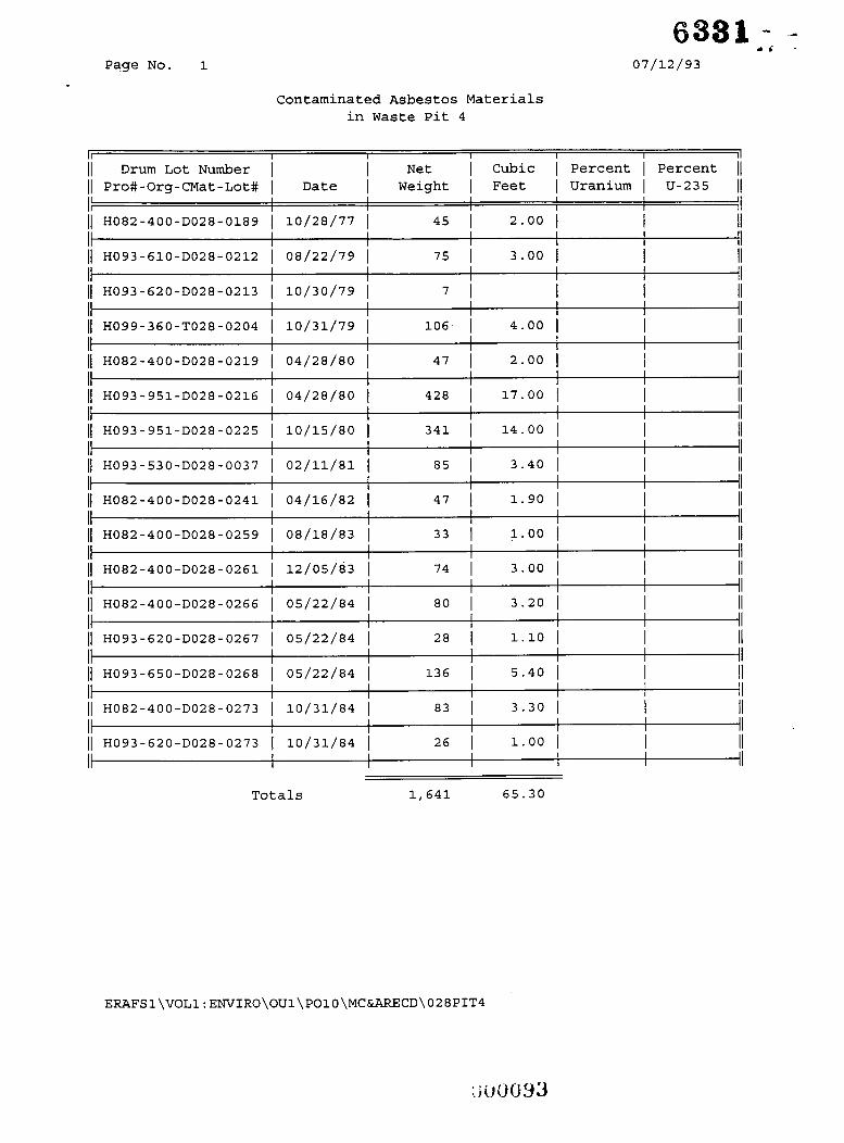
6 3 8 1 - Page NO. 1
r i - 07/12/93
Contaminated Asbestos Materials in Waste Pit 4
II I I I I I il 1 1 Drum Lot Number I I Net I Cubic I Percent I Percent 11 1 1 Pro#-Org-CMat-Lot# I Date I Weight I Feet I Uranium I U-235 11
11 H082-400-D028-0189 I 10/28/77 I
11 H093-610-D028-0212 I 08/22/79 I
I I I I I I I I I I I1
45 I 2.00 I I II I I I I I 11
I II
II
II I I I I
75 I 3.00 I II I I I I 1
11 H093-620-D028-0213 1 10/30/79 i 7 1 I I II I I I I I I I II
106- I 4.00 I I II I1 11 H099-360-T028-0204 I 10/31/79 I II I I I I I I 1
I I I I (1 H082-400-D028-0219 I 04/28/80 I 47 I 2.00 I I II
I I I I I II 428 I 17.00 I I II
I1
I I I I II 341 I 14.00 I I II
II
I I I I I II 85 I 3.40 I I II
II
I I 1 II 47 I 1.90 I I II
I 1
I I I I I II 33 I 1.00 I I II
II I I I I I I1
74 I 3.00 I I II II
I I I I II 80 I 3.20 I I II
II
I I I {I 28 1 1.10 1 I II
II
I I I I iI 136 I 5.40 I I II
II
I I I I II 83 I 3.30 I I II
II
I I I I I II 26 I 1.00 I I II
It
It I I I I I 1
11 H093-951-D028-0216 I 04/28/80 I I I I I
11 H093-951-D028-0225 I 10/15/80 1 I I I I
11 H093-530-D028-0037 I 02/11/81 I I I I I
11 H082-400-D028-0241 I 04/16/82 I I I I I
11 H082-400-D028-0259 I 08/18/83 I I I I I
11 H082-400-D028-0261 I 12/05/83 I I I I I
11 H082-400-D028-0266 I 05/22/84 1 I I I I
11 H093-620-D028-0267 I 05/22/84 I I I I I
11 H093-650-D028-0268 I 05/22/84 I I I I I
1 1 H082-400-D028-0273 I 10/31/84 I I I I I
1 1 H093-620-D028-0273 I 10/31/84 1 I I I I
65.30 Totals 1,641

Page No. 1
I I I I I I I II
6881 07/12/93
Contaminated Soil, Rocks, Sand, Bricks, and Ceramics in Waste Pit 4
I I I I II j / S035-643-Doll-0199 j 01/05/79 I 1303 I 9.00 I 0.65 I 0.3500 1 1 I I I I I II I I I I 1
11 H093-610-Doll-0202 I 02/12/79 I 105 I 1-00 I I II II I I I I I II
11 H082-732-Doll-0204 I 04/17/79 I 44 I 0.33 I I II I I I1
51 I 0.33 I I II I 1 I I I I
11 H082-732-Doll-0206 I 04/17/79 I
ii II I I 1 I I 11 H082-732-Doll-0207 I 04/17/79 I 42 I 0.33 I I
)I H082-732-Doll-0212 I 08/22/79 1 79 I 0.50 I I II II I I - - I I
- -
)I S103-761-0011-0213 I 10/16/79 I I 49.00 I 0.18 j 1.0300 i j I I I I I
I I I I1 930 I 6.00 I I II
I 1 1 1 H093-610-Doll-0211 I 10/30/79 1 II I I I I II
1 1 H093-732-Doll-0213 i 04/28/80 I 46 I I I II I I I I I I I II
86 I 1.00 I I I/ II
II I I I II 11 H093-732-Doll-0219 I 07/23/80 I 46 I I I II
I I I I II 93 I 1.00 1 I II
I 1
(1 H093-732-Doll-0214 I 04/28/80 1 I I I I
I I
11 H093-732-Doll-0223 I 09/10/80 I I1 1 1 I I I ii 11 H093-643-0011-0223 I 10/15/80 I 4393 I 29.00 I I II I I I I I II 11 H093-732-Doll-0224 I 10/15/80 I 44 I I I II
I I I I
II I--- ~ I I I II
I I I I 11 H093-642-Doll-0226 I 02/11/81 I 51 I 0.30 I I /I
I II 50 I 0.30 I I II
II
I 1 I I I I I II 1 1 H093-732-Doll-0225 I 02/11/81 I
I I I I

Page No. 2 07/12/93
Contaminated Soil, Rocks, Sand, Bricks, and Ceramics in Waste Pit 4
II I I I I I 11
11 Drum Lot Number I I Net I Cubic I Percent I Percent 11 11 Pro#-Org-CMat-Lot# 1 Date I Weight I Feet I Uranium I U-235 11
9 I I ii H093-732-Doll-0226 i 02/11/81 i 40 1 0.30 1 I II 11 S052-645-Doll-0214 I 02/11/81 I 9671 I 64.50 1 2.51 I 0.5170 11
I I I I I It I I I II 1 1 H093-732-Doll-0227 I 04/15/81 I 44 I I I II
ii II I I 1 I I
11 H093-510-Doll-0004 I 03/25/82 I 595 I 4.00 I I I1 I I I I
I I I II 261 I 1.70 I I II 11 H093-642-Doll-0232 I 03/25/82 I
II 1 - 1 - 1 I I II _______-
1 1 H093-732-Doll-0232 I 03/25/82 I 86 I 0.60 I I II
1 1 H093-732-Doll-0233 I 03/25/82 I 126 I 0.80 I I II 1 I I ll
105 I 0.70 I I II It
I I I {I II
I I I I II 168 I 1.00 I I II
II
I I I I
11 H093-732-Doll-0234 I 04/16/82 I I I I I
83 I 0.60 I 10.25 I 0.3400 11 11 H093-732-Doll-0236 I 04/16/82 I I I I I I
11 H093-732-Doll-0245 I 06/14/82 I II I I I I I
I I I I 11 H093-642-Doll-0246 i 07/07/82 i 868 1 6.00 I I II II I I I I I 1 11 H093-732-Doll-0246 I 08/11/82 I 40 I I I II II I I I I I I
_ _ _ _ ~
1 1 H093-732-Doll-0248 i 03/10/83 I 236 I 1.60 I 4.18 I 0.5010 11
I 43.78 I 0.3180 11 I I I I I I I I I I II II
1) H082-732-Doll-0257 1 08/18/83 I 40 I I I {I
3615 1 24.00 I I II It
I I II II
I II 226 I 2.00 I I I1
II
I I II 1101 I 7.30 I I II
II I I I I II
122 I 0.80 I I II I 1
I I I I 11 II
I I II 351 I 2.30 I I II
II I I I I I I 1
187 I 1.25 I I II II
I 1 I I I I iI
I I I I
11 H093-517-Doll-0259 1 08/18/83 I I I I I
107 I 0.71 I 4.60 I 0.3900 11 1 1 ???9-510-D011-0261 I 01/09/84 1 I I I I I
11 ???3-510-D011-0263 I 01/09/84 I I I I I
I( ???3-517-D011-0261 I 01/09/84 I I I I I
11 ???3-732-D011-0261 I 01/09/84 I I I I I
444 I 3.00 1 1.30 I 0.3770 11 11 H093-300-Doll-0265 I 01/26/84 I I I I I I
11 H093-732-Doll-0266 I 03/09/84 I I I I I
11 H093-510-Doll-0267 I 05/22/84 I I I I I

Page No. 3
6331 . .
07/12/93
Contaminated Soil, Rocks, Sand, Bricks, and Ceramics in Waste Pit 4
II I I I I I ( I
11 Drum Lot Number I I Net I Cubic I Percent I Percent 11 11 Pro#-Org-CMat-Lot# I Date I Weight I Feet I Uranium 1 U-235 11
11 H093-510-Doll-0270 I 08/02/84 1 288 I 1.90 I I II I 1 I I I I I I 1
I I I I 11 H093-732-Doll-0269 I 08/02/84 1 205 I 1.40 I I II
I I I I I II 522 I 3.70 I I II
It
I I I I I 4 976 1 6.50 I I II
I1
I I I I iI 464 I 3.10 I I II
II
II I I I I II
11 H093-510-Doll-0272 I 10/31/84 I I I I I
11 H093-517-Doll-0273 I 10/31/84 I I I I I
11 H093-732-Doll-0274 I 10/31/84 1 I I I I
Totals 38,282 331.85

I I I I 3 .A2 . . > . I .* . . I I

I
s31w
1 I 9 s I