© 2014 Fluke Corporation Fluke Calibration Web Seminar Series Principles and practical tips about...
31
© 2014 Fluke Corporation Fluke Calibration Web Seminar Series Principles and practical tips about electrical, flow, pressure, RF and temperature calibration How to Set-up a Thermocouple Calibration System
-
Upload
samson-spencer -
Category
Documents
-
view
223 -
download
0
Transcript of © 2014 Fluke Corporation Fluke Calibration Web Seminar Series Principles and practical tips about...

© 2014 Fluke Corporation
Fluke Calibration Web Seminar SeriesPrinciples and practical tips about electrical, flow, pressure, RF and temperature calibration
How to Set-up a Thermocouple Calibration System

Today’s Web Seminar
How to Set-up a Thermocouple Calibration System
October 1, 2014
Thermocouples are broadly used in many industrial and scientific applications. Attend this free web seminar to learn the fundamentals of how thermocouples work and the components needed to set-up a thermocouple calibration system. We’ll give you the basics to understand the main techniques for calibrating thermocouples (including the pros and cons) at both the industrial level and in the calibration lab. System uncertainties, best practices, and tips/tricks for conducting a successful thermocouple calibration will be covered.
This web seminar is for those who are currently using a thermocouple calibration system and want to improve it or those new to thermocouple calibration who are building a calibration system.

Fluke Calibration
• Fluke Calibration– Electrical (Everett, WA)– RF (Norwich, UK)– Temperature (American Fork, UT) – Pressure/Flow (Phoenix, AZ)
• Presenter: Michael Coleman– Director of Temperature Metrology
• With Fluke/Hart Scientific 16 years– Primary Temperature Calibration Lab– TCAL Service Department
Fluke Calibration, Temperature, American Fork, UT
3

Learning Objectives
• Thermocouple characteristics • Theory of operation• Thermocouple types• Calculations – voltage to temperature
conversion, readout accuracy• Typical calibration scenarios• Calibration schemes and equipment
4
Type S or R Thermocouple Standard
9118A Thermocouple Calibration Furnace
1586A Super-DAQ and DAQ-STAQ Multiplexer
Thermocouple Characteristics
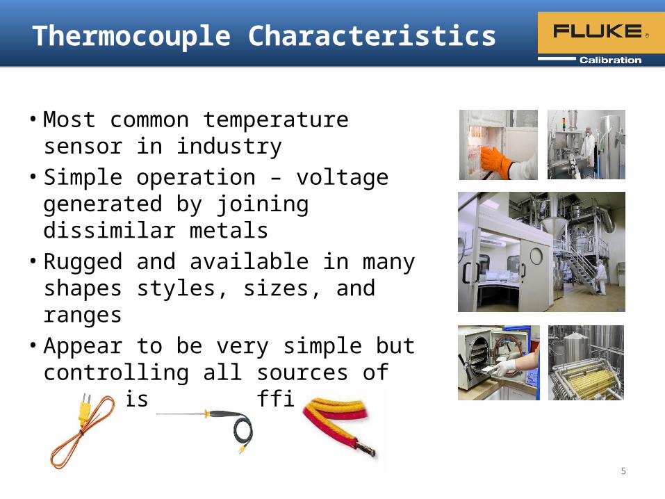
• Most common temperature sensor in industry
• Simple operation – voltage generated by joining dissimilar metals
• Rugged and available in many shapes styles, sizes, and ranges
• Appear to be very simple but controlling all sources of error is very difficult
5

Typical Accuracies
• Base metal thermocouples (Type E, K, N, etc.) range from about ± 1 ºC to 10 ºC accuracy
• Noble metal thermocouples (Type S, R) accuracies range from ± 0.6 ºC to 2.7 ºC but can be calibrated to improve accuracy
• Special thermocouple types (gold vs. platinum, platinum vs. palladium) may achieve accuracies in the ± 0.01 ºC to 0.05 ºC range with calibration
• Main source of error is inhomogeneity (wire inconsistency)– Inconsistent alloy distribution– Oxidation– Metal migration– Strain in the wire
6

Useful Tips (from NMI New Zealand)
• Bending the wire in a temperature gradient region can cause a 3 ºC shift in a Type K temperature reading
• Prolonged high temperature exposure can cause a Type K to change as much as 100 ºC due to oxidation
– 1% change in Seebeck coefficient per 1000 hours at 1000 ºC
• A simple test for checking inhomogeneity:1. Lay a thermocouple on a bench and connect it to a readout
2. Blow a heat gun over different sections of the wire while watching the readout display
3. If the readings fluctuate significantly, the thermocouple is inhomogeneous
4. Replace if inhomogeneity is detected
Source: “Making Sense of Thermocouples”, Measurement Standards Laboratory of New Zealand, https://www.msl.irl.cri.nz/sites/all/files/training-manuals/TG14-July-2009.pdf
7
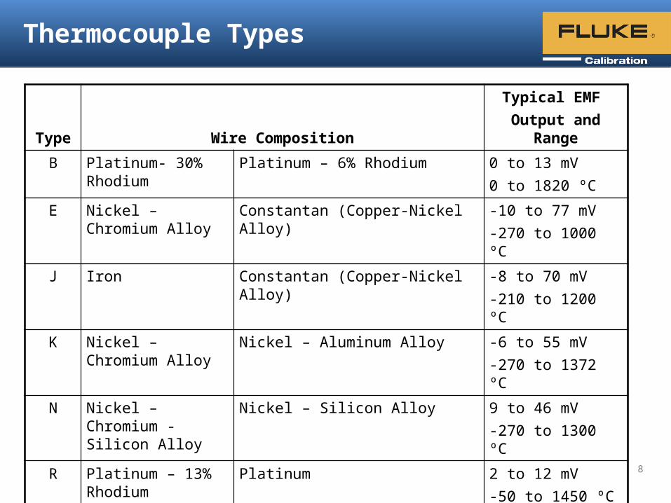
Thermocouple Types
Type Wire CompositionTypical EMF
Output and Range
B Platinum- 30% Rhodium
Platinum – 6% Rhodium 0 to 13 mV0 to 1820 ºC
E Nickel – Chromium Alloy
Constantan (Copper-Nickel Alloy) -10 to 77 mV-270 to 1000 ºC
J Iron Constantan (Copper-Nickel Alloy) -8 to 70 mV-210 to 1200 ºC
K Nickel – Chromium Alloy
Nickel – Aluminum Alloy -6 to 55 mV -270 to 1372 ºC
N Nickel – Chromium - Silicon Alloy
Nickel – Silicon Alloy 9 to 46 mV-270 to 1300 ºC
R Platinum – 13% Rhodium
Platinum 2 to 12 mV-50 to 1450 ºC
S Platinum – 10% Rhodium
Platinum 2 to 11 mV-50 to 1450 ºC
T Copper Constantan (Copper-Nickel Alloy) 4 to 19 mV-270 to 400 ºC
8

Thermocouple Theory of Operation
Thermocouples measure relative temperature: a differential measurement between the hot junction (T1) and the cold junction (T2), between which a voltage potential is generated
T1: Hot junction (also called measuring junction) T2: Cold junction (also called
reference junction)
VT2
T1
A
B
C
C A: thermocouple wireB: thermocouple wireC: copper wire
9

Theory of Operation – Further Detail
• Potential (voltage output) varies as overall temperature differential changes
• Voltage output ranges from -15 to 70 mV (depending on type of thermocouple and measurement temperature)
• Voltage output is proportional to temperature, but the effect is not linear
• Voltage potential is caused by differing electron densities along temperature gradients
– Voltage is created in zones of temperature gradient only– Entire thermocouple is the sensor– Measured voltage is net total of infinitesimally small
temperature gradients (Seebeck effect)
10

Measure Junctions
• Need 2 junctions to work – reference junction and measure junction• Junctions can be created by twisting, crimping, soldering, or
welding the wire• Voltage isn’t generated by the junction itself – Why?
– The junctions are kept in isothermal zones (no gradients) so no voltage is generated (uniform zone in furnace, uniform zone in ice bath)
VT2
T1
A
B
C
C
Majority of voltage generated in this region
11

Reference Junctions – 2 Approaches
• Reference junction is where the transition from thermocouple wire to copper wire is made – Why?– Copper wire can be connected to a meter with no additional voltage
potential
• We need to know the temperature of the reference junction so we can correct the measured voltage– Keeping it at 0 ºC is easiest, no correction needed: Use an ice bath
or ice point furnace– Can be kept at other temperatures but correction is required
• So what are the 2 main approaches?1. External reference junction (copper wires attached and junction placed in a
stable temperature environment) – Best Accuracy! (as good as ± 0.005 ºC)
2. Internal reference junction (connect TC wire to the meter, the meter compensates automatically) – Accuracy varies from meter to meter (± 0.05 to 0.6 ºC)
12

Typical Ice Bath Reference Junction Setup
• Vacuum insulated dewar flask• Shaved ice mixed with water• Thermistor probe monitors
temperature of ice bath
13

+
-
+
-V (T )T C T C
V (0°C)J 1
[V (0°C)+V (0°C)=0]J1 J2
V (0°C)J 2
0°C
V =V (T )o T C T C
Ice Bath
External Reference Junction
14

Internal Reference – Junction Compensation Circuit
+
-
+
-V (T )T C T C
V (T )J1 J
V (T )J2 J
T J
V =V (T )+[V (T )+V (T )]o T C T C J 1 J J 2 J
1586A Super-DAQInternal High-Capacity Module
15

Meter Accuracy Specifications
• 1586A Super-DAQ thermocouple measurement specs:
• 1560 Black Stack with 2565 Module thermocouple measurement specs:
16
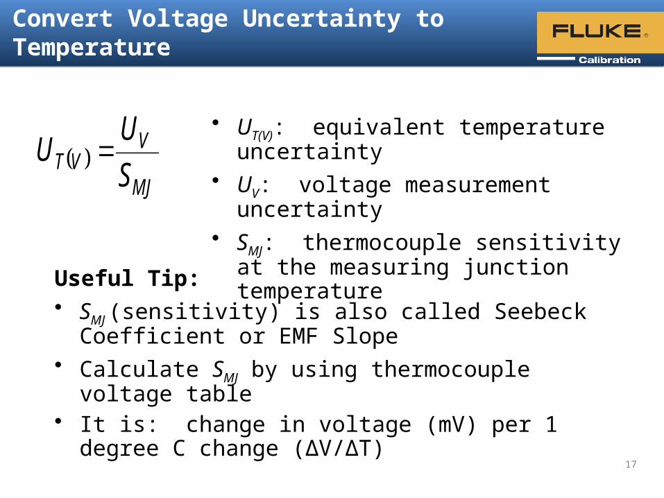
Convert Voltage Uncertainty to Temperature
MJ
VVT S
UU
• UT(V): equivalent temperature uncertainty• UV: voltage measurement uncertainty• SMJ: thermocouple sensitivity at the
measuring junction temperature
Useful Tip:• SMJ (sensitivity) is also called Seebeck Coefficient or
EMF Slope• Calculate SMJ by using thermocouple voltage table• It is: change in voltage (mV) per 1 degree C change
(ΔV/ΔT)
17

Accuracy Calculation Example
• The thermocouple is type S
• The temperature is 1000 ºC
• The voltage at 1000 ºC is 9.6 mV
• The specified voltage accuracy in this range is 0.002 mV
• The TC has a sensitivity of 0.0115 mV/ºC at 1000 ºC
• What is the equivalent temperature uncertainty?
CU VT
17.0CmV0115.0
mV002.0
18
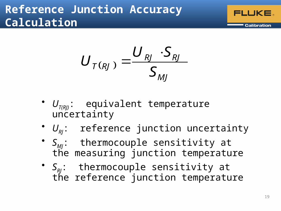
Reference Junction Accuracy Calculation
MJ
RJRJRJT S
SUU
• UT(RJ): equivalent temperature uncertainty• URJ: reference junction uncertainty• SMJ: thermocouple sensitivity at the measuring
junction temperature• SRJ: thermocouple sensitivity at the reference
junction temperature
19

Reference Junction Example
• The thermocouple is type S
• The temperature is 1000 ºC
• The reference junction accuracy is 0.05 ºC
• The TC has a sensitivity of 0.0115 mV/ºC at 1000 ºC
• The TC has a sensitivity of 0.006 mV/ºC at 25 ºC
• What is the equivalent temperature uncertainty?
CU RJT
026.0
CmV0115.0
CmV0060.0C05.0
20
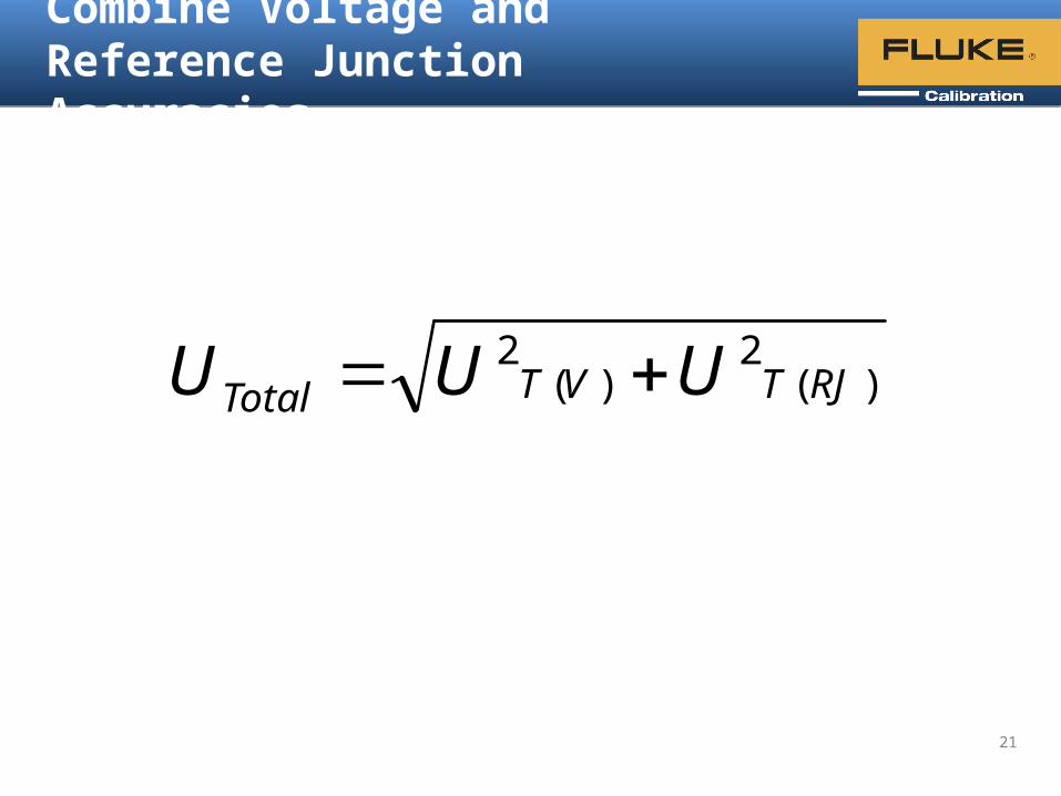
Combine Voltage andReference Junction Accuracies
)(2
)(2
RJTVTTotal UUU
21

Two Calibration Options
Tolerance test– Measure temperature points– Verify if results are in or out of
tolerance– Replace if out of tolerance
Characterize– Gather temperature vs. voltage data– Measure enough points to calculate
coefficients or offsets– Typically only applies to noble metal
Cautions– Difference in gradient profiles between cal setup and
application/point of use will introduce errors with inhomogeneous thermocouples
– Removing and calibrating base metal thermocouples can cause them to shift. If measuring above 300 ºC, may be best to just replace.
22

Calibration Schemes
In situ– Comparison– Simulation
Cal lab– Comparison– Fixed-point– Simulation
23

Basic Comparison Calibration Scheme
• Compare UUT thermocouples against a reference temperature probe or display of the heat source
• Probes are inserted into a heat source (drywell, furnace, or bath)• UUTs are connected to a reference meter or stay connected
to own readout for system calibration (readout and probe calibrated as a system)
24

Comparison Calibration Equipment
• Heat source– Drywell or Metrology Well for -90 to 700 ºC– 9150 vertical furnace up to 1200 ºC– 9118A horizontal furnace up to 1200 ºC– Stability and uniformity are important specs– Furnaces and drywells with zone control are best
• Readout– Largest errors typically from internal RJ circuit– Readouts that measure both PRTs and TCs are
most useful
25
9118A Thermocouple Calibration Furnace
1586A Super-DAQ and DAQ-STAQ Multiplexer
Tip: Take your calibration lab productivity to the next level. Use the 1586A Super-DAQ with a 9118A furnace to automate thermocouple calibration. Watch the video »
914X Field Metrology Well
9150 Vertical Furnace

Comparison Calibration Equipment
• Reference probe– For -200 to 962 ºC, use PRT or SPRT (±0.05 ºC or
better) (Fluke model 5628, 5624, 5699)– For higher temperatures, use noble metal Type S or
Type R (±0.3 ºC and up)
• External reference junction– Ice bath works well– Can use stirred-liquid bath or specialized
drywell set to 0 ºC
9101 Zero-Point Drywell
26
Type S or R Thermocouple Standard
PRT or SPRT

Measurement Tips
• In open cavity, mount UUT probes around reference probe
• Allow sufficient time for stability and uniformity to be achieved
• Use heat source ramp control to avoid over-shooting
[Calibrating a bundle of thermocouples without a block] [Calibrating ceramic-sheathed thermocouples with a block]
27

Total System Uncertainty Analysis
• Readout accuracy (for reference probe and UUT)
• Reference junction accuracy (external or internal)
• Reference probe accuracy (calibration uncertainty and drift)
• Heat source uniformity (axial and radial gradients)
• Heat source stability (affects measurement standard deviation)
• Other (ambient conditions, inhomogeneity of UUT, etc.)
28

References and Useful Links
• “Making Sense of Thermocouples”, Measurement Standards Laboratory of New Zealand, https://www.msl.irl.cri.nz/sites/all/files/training-manuals/TG14-July-2009.pdf
• ASTM E230• NIST SP250 (NIST TC calibration program)• NIST Monograph 175• “How to Calibrate a Thermocouple”, Fluke Calibration application note
(available soon)
• NIST thermocouple database http://srdata.nist.gov/its90/main/

© 2014 Fluke Corporation.
Future web seminarsTemperature Calibration seminars coming soon:
• October 8: Annealing an RTD: Why, When, and How (presented in English)
• October 22: Annealing an RTD: Why, When, and How (presented in Spanish)
• November 12: Understanding Uncertainties Associated with Dry-block Calibrators (presented in English)
For the latest schedule visit
www.flukecal.com/calwebsem
Our seminar topics cover principles and practical tips about electrical, flow, pressure, RF and temperature calibration

© 2014 Fluke Corporation.
Thank youBe the first to know. Sign up for Fluke Calibration e-news bulletins, and the quarterly Total Solutions in Calibration newsletter:
www.flukecal.com/signmeup

![CERTIFICATE OF CALIBRATION - Fluke Caldownload.flukecal.com/pub/literature/9010444_ENG_A_W[1].pdf · AC Voltmeter Fluke 5790A 9380036 C1/778B 29 May 2011 ... CERTIFICATE OF CALIBRATION](https://static.fdocuments.us/doc/165x107/5bdcd85509d3f2321d8c1ad2/certificate-of-calibration-fluke-1pdf-ac-voltmeter-fluke-5790a-9380036-c1778b.jpg)