© 2012 Delmar, Cengage Learning Electronic and Computer Systems Service Chapter 46.
35
© 2012 Delmar, Cengage Learning Electronic and Computer Systems Service Chapter 46
-
Upload
amberlynn-roberts -
Category
Documents
-
view
216 -
download
0
Transcript of © 2012 Delmar, Cengage Learning Electronic and Computer Systems Service Chapter 46.
© 2012 Delmar, Cengage Learning
Electronic and Computer Systems Service
Chapter 46

© 2012 Delmar, Cengage Learning
Objectives• Diagnose related engine and electrical problems
prior to computer repair• Describe the theory and operation of on-board
diagnostics• Read trouble codes• Use a scan tool• Confirm closed loop• Test sensors and actuators• Diagnose computer wiring problems• Diagnose and replace a computer
© 2012 Delmar, Cengage Learning
Introduction• Computer systems have become sophisticated
– Necessary to consult model-specific service information
• Step-by-step procedures for troubleshooting
– Today's technicians must be able to read a wiring schematic
• In order to diagnose and repair modern computerized vehicles

© 2012 Delmar, Cengage Learning
Inspection Sequence• Computers have self-diagnostic ability
– Logical diagnosis sequence must be followed before checking computer
• Digital multimeter– Used to measure electricity in electronic circuits
• Visual inspection– Can often determine problem cause

© 2012 Delmar, Cengage Learning
Perform Diagnostic Tests• Analyze the cause of the problem rather than
just fixing the problem’s result– Listen during cranking for an even rhythm and
then for a smooth idle
– Check base timing setting on engines with a distributor ignition
– Do a charging system test before beginning a diagnostic procedure

© 2012 Delmar, Cengage Learning
On-Board Diagnostics• Computers detect incorrect electrical conditions
– Save trouble codes to memory• Key is turned on: computer does a self-check of
its circuits
• Diagnostic tree– Provides a step-by-step diagnostic procedure
• Sensors – Cause electronic control problems more often
than actuators

© 2012 Delmar, Cengage Learning
Reading Trouble Codes• Different ways to read trouble codes
– OBD II systems have standardized connectors and procedures
– Most systems have a diagnostic link connector (DLC)
• Scan tool can be connected to it to read codes• Procedure for retrieving fault codes varies

© 2012 Delmar, Cengage Learning
Scan Tools• Portable computer
– Reads data from the on-board computer
– Have specific software cartridges
– Handheld and can be taken on a road test
– Limited to diagnosing computer problems
• Communication between scan tool and computer– Unidirectional or bidirectional
• Parameter identification data– Included in on-board diagnostics
© 2012 Delmar, Cengage Learning
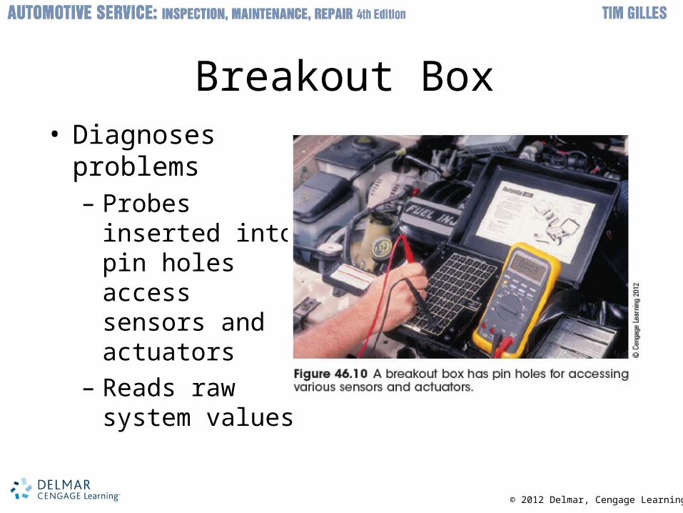
Breakout Box• Diagnoses
problems– Probes inserted
into pin holes access sensors and actuators
– Reads raw system values

© 2012 Delmar, Cengage Learning
Retrieving Trouble Codes• OBD I
– Scan tools were not so widely owned by automotive technicians
• OBD II scan tools – Powered through the DLC
– Do not disconnect or connect while the key is on
– Remove before removing connections to electronic components
© 2012 Delmar, Cengage Learning
Working with Codes• More than one code is given
– Fix the lower number code first
– Fix the problem first and then start again
– Be sure to check power and grounds
– Erase codes and test drive the car to reset codes
• OBD II cars– Scan tool must be used to read codes
© 2012 Delmar, Cengage Learning
Erasing Trouble Codes• Code can remain in memory even though a
problem has been corrected– Clear codes after the repair has been made
• Older vehicles: procedure that shuts off power to computer can be used to erase codes
• OBD II vehicles: scan tool command required • Manufacturer's methods vary
• Scan tool – Erases codes without disconnecting anything
– Test drive car to see if any codes return

© 2012 Delmar, Cengage Learning
Scan Tool Snapshot• Scan tool has a feature like an airplane flight
recorder– Helps catch glitches and intermittent problems
• Settings– Snapshot: series of pictures representing the
conditions present when the DTC was set
– Automatically record when any fault code occurs during the test drive
– Freeze frame

© 2012 Delmar, Cengage Learning
Closed Loop• Computers require correct inputs from sensors
and correct actions from actuators– Several things must occur for a computer system
to go into closed loop
• Methods for confirming closed loop vary– Examples: DMM, scan tool, and a lab scope
– Do not use ohmmeter to test an oxygen sensor

© 2012 Delmar, Cengage Learning
Fuel Trim Diagnosis• Diagnosing fuel trim with scan tool
– Drive vehicle under same conditions where problem occurred
– Restricted fuel filter or low fuel pump output increase fuel trim under load
– Leaks that allow air into intake system result in higher fuel trim values
– Plugged or sticking fuel injector affects fuel trim cells equally as rpm increases

© 2012 Delmar, Cengage Learning
Digital Waveforms• Waveform
– Better diagnostic tool than digital volt-ohmmeter
• Tools capable of displaying voltage or frequency in waveform– Digital storage oscilloscopes
– Graphing multimeters
– Four channel scopes • Can display four waveforms

© 2012 Delmar, Cengage Learning
Logic Probe/Power Probe• Three colored LEDs instead of one bulb
– Touching probe to ground lights green LED
– Red LED illuminates when touched to a power source
– Yellow light comes on when a pulsed voltage is sensed
© 2012 Delmar, Cengage Learning
Sensor and Actuator Testing• Sensor testing strategy
– No-start condition occurs if a distributor reference or crankshaft sensor signal is lost
– Defective or misadjusted TPS can send an excessive voltage to computer as WOT
– With the key on, do not disconnect any electrical components unless instruction says to do this

© 2012 Delmar, Cengage Learning
Diagnosing Sensor Problems• When using a scan tool to diagnose sensors
and actuators, use the following sequence:– Check input sensors
– Perform a quick check of input switches
– Check outputs
• Sensor types– High authority sensors
– Passive sensors
– Active sensors

© 2012 Delmar, Cengage Learning
Sensor Tests• Vehicle speed sensor
– Supplies input for electronic speedometers and cruise control systems
• Also controls torque converter clutch
• Types of speed sensors– Photoelectric and magnetic AC generator
• Failed sensor can cause:– Premature or no converter clutch lockup
– Lack of change in steering assist
– Inoperative cruise control and speedometer

© 2012 Delmar, Cengage Learning
Oxygen Sensor• Enriches mixture so reduction catalyst can work
– Must provide a lean enough mixture for hydrocarbons and carbon monoxide to oxidize
• Characteristics– Start-up varies
– Lazy sensor produces voltage slowly and does not change back and forth
– Range is tested by creating full rich and full lean conditions
– Wide range oxygen sensors can accurately detect air-fuel ratios over a wide range

© 2012 Delmar, Cengage Learning
Load Sensors• Include MAP, vacuum, and MAF
– Tell computer how much air is entering engine
– Affect ignition timing and air-fuel ratios
© 2012 Delmar, Cengage Learning
MAP Sensor and BARO Sensors• MAP sensor
– Basic fuel delivery to the engine is determined by MAP sensor, CKP, and ECT
– Engine load is high: fuel injectors are on longer
– Vacuum higher: MAP sensor voltage drops
• BARO sensors– Monitor changes in weather or altitude
– Several different types
– Defective sensor causes poor high-altitude performance or spark knock
© 2012 Delmar, Cengage Learning
Vacuum Sensors• Measure difference between atmospheric
pressure and intake manifold pressure– Systems that use vacuum sensors must also use
BARO sensors
– BMAP is a combination barometric and MAP sensor

© 2012 Delmar, Cengage Learning
Throttle Position Sensor• Potentiometer mounted on throttle shaft
– Defective or misadjusted TPS causes hesitation when accelerating
• Check with voltmeter or ohmmeter

© 2012 Delmar, Cengage Learning
Coolant Temperature Sensor and Air Temperature Sensors
• Coolant temperature sensor – Affects how the engine operates in all conditions
– Common problem: computer system will not go into closed loop when engine is warm
– Use ohmmeter or voltmeter to test
• Air temperature sensors– IAT sensor works like a coolant temperature
sensor• Fine tunes air-fuel mixture• Compensates for air density

© 2012 Delmar, Cengage Learning
Airflow Sensor Service• Fuel systems controlled by an airflow sensor
– React poorly to vacuum leaks
– Dirt causes problems in vane airflow sensor
– Intake manifold popback causes the door to bend or break
• MAF sensors have no moving parts– Hot film MAF sensors produce a variable
frequency instead of voltage

© 2012 Delmar, Cengage Learning
Knock Sensor Service• Help prevent engine knock
– Loose bracket or other vibration causes retarded timing
– Computer senses an inoperative knock sensor: P0324 through P0334 code will set
– Broken or damaged knock sensor wiring is often the cause of a knock sensor code
– Test by rapping on the engine near sensor with a metal tool
– Many engines use a newer style of knock sensor, called a resonance knock sensor

© 2012 Delmar, Cengage Learning
Actuator Service• Actuators include:
– Solenoids
– Fuel injectors
– Stepper motors
– Motors for electronic suspension hydraulic controls
• Test an actuator– Done by checking for voltage at actuator control
terminal
– Test according to individual service instructions

© 2012 Delmar, Cengage Learning
Repair the Problem• After repairing problem
– Road test vehicle again• Test drive allows a late-model computer to relearn
its best adjustments
– Use scan tool to erase codes
• After replacement of the computer or when a battery has been disconnected– Poor drivability and performance can result until
computer relearns best drivability settings
© 2012 Delmar, Cengage Learning
Computer Wiring Service• Common cause of problems in computer
systems– Poor electrical connections
• Include loose or corroded connections and grounded wires
• Always use a wiring diagram when working on computer systems– Computer must have good power and ground
connections
– Twisted pair wiring carries very small amounts of current
© 2012 Delmar, Cengage Learning
Computer Wiring Service (cont’d.)
• Electronic updates – Regular occurrence among manufacturers
• Battery voltage must be stable during reprogramming– Can take an hour or more to complete
• Computer location– Usually mounted in driver’s compartment

© 2012 Delmar, Cengage Learning
Static Electricity• Static electricity from the front seat is a concern
– People who work around sensitive components sometimes wear a ground strap
– Touch ground before touching computer
– Do not take the computer out of container until you are already in the front seat

© 2012 Delmar, Cengage Learning
Electrical Damage to a Circuit• Too much electrical current
– Causes heat that damages an electrical circuit
– Damaged connections are usually the reason for failure
– Semiconductors are designed for only a limited amount of current
– Bus diagnosis is similar to other electrical system diagnoses

© 2012 Delmar, Cengage Learning