![GunnDiode new.ppt [Read-Only] - Educypedia, The ...educypedia.karadimov.info/library/GunnDiode.pdf · Schematic diagram for n-type GaAs diode GunnEffect + Anode ... • Gunndiode](https://static.fdocuments.us/doc/165x107/5ab823347f8b9ac60e8c7408/gunndiode-newppt-read-only-educypedia-the-diagram-for-n-type-gaas-diode.jpg)
-1- - Educypedia, The educational encyclopedia is the most...
26
-1- A survey of rotordynamics by Marc Crooymans WFW 84.01 1 March 1984 These investigations were supported (in part) by the Netherlands Foundation for Technical Reasearch (STWJ, Future Technical Science Branch/Division of the Netherlands Organization for the Advancement of Pure Research (ZWO).
Transcript of -1- - Educypedia, The educational encyclopedia is the most...

- 1 -
A survey o f rotordynamics
by Marc Crooymans
WFW 84.01 1 March 1984
These investigations were supported (in part) by the
Netherlands Foundation for Technical Reasearch (STWJ, Future Technical Science Branch/Division of the
Netherlands Organization f o r the Advancement o f Pure Research (ZWO).
-2-
Content
1 . i n t ~ ~ ~ u c t i o n ................. ....................page 3
2.Rotordynamics terminology ...................... page 4
3.Literature survey .............................. page 13
4.Subjects for further investigation ............. page 21
References

- 3 -
1.Introduction
In this report we introduce the field of fundamental concepts concerning rotordynamics which includes the vibration o f rotating machinery. The investigations concentrate on the rotating parts, called the rotor. Frequent applications for rotatiny machinery are motors, drills, pumps, turbines and mills which emphasizes the importance of this subject. Differences in geometry, material , assembly and use make it impossible to treat the subject completely; therefore, we will restrict ourselves to: 1: an introduction of rotordynamics terminoloyy. 2: a survey of rotordynamics literature 3 : and a list of some feasible subjects of investigation
This report will be the starting point of future investigations in the field of non-linear rotordynamics.

-4-
2.Rotordvnamics terminoloqv
In general, rotating equipment. i s modelled as a rotor mounted in bearings. The bearings are fitted into the casing of the rotor which is attached to a foundation. The rotor revolves in a liquid or a gas inside its casing and it is connected to other rotor systems by means of gears or couplings.
Characteristically, the rotor is a mechanism with one rotational degree of freedom. In general, the rotational axis is very close to one of the principal axis of the rotor. The rotor oft.en consists of a rotating symmetrical shaft on which several parts are mounted such as blades or vanes. The shaft diameter may vary along its centre line.
An normal rotor mounted in two bearings is shown in fig.1. The rotor is by a circular shaft of constant diameter and its rotational velocity, or the rotor speed, is given by R (rad/s). Section A-A is a cross- section of the shaft.
represented
fig e 1 : a rotor system
section A-A
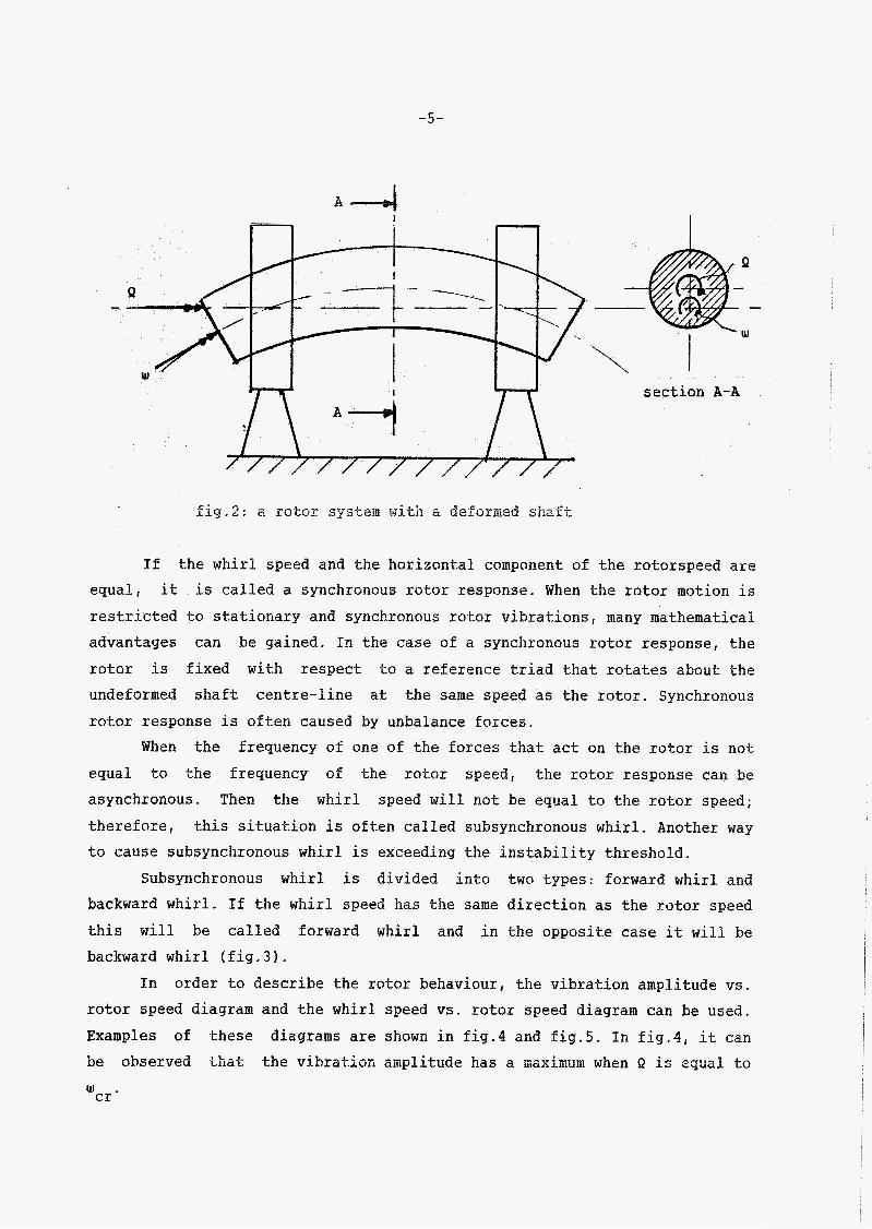
When the shaft is out of balance, it will deform (see fig.2). Now, in section A-A, we can distinguish two rotational velocities: the rotor speed R which is the rotational speed about the deformed shaft centre line and the whirl speeâ w which is t h e rotational velocity âblrüt the üridefûïiììzd shaft centre line.
-5-
A I
\ section A-A
Eig.2: a rotor system with a deformed shaft
If the whirl speed and the horizontal component of the rotorspeed are equal, is called a synchronous rotor response. When the rotor motion is restricted to stationary and synchronous rotor vibrations, many mathematical advantages can be gained. In the case of a synchronous rotor response, the rotor is fixed with respect t o a reference triad that rotates about the undeformed shaft centre-line at the same speed as the rotor. Synchronous
it
rotor response is often caused by unbalance forces. When the frequency of one of the forces that act on the rotor is not
equal to the frequency of the rotor speed, the rotor response can be asynchronous. Then the whirl speed will not be equal to the rotor speed; therefore, this situation is often called subsynchronous whirl. Another way to cause subsynchronous whirl is exceeding the instability threshold.
Cubsynchronous whirl is divided Into two types: forward whirl and backward whirl. If the whirl speed has the same direction as the rotor speed this will be called forward whirl and in the opposite case it will be backward whirl (fig.3).
In order to describe the rotor behaviour, the vibration amplitude vs. rotor speed diagram and the whirl speed vs. rotor speed diagram can be used. Examples of these diagrams are shown in fig.4 and fig.5. In Eig.4, it can be observed that the vibratiûn aitiplitüde has a maximm when c! is ecjuâ? to w cr ’

&- - -- w
I
A ) forward whirl B) backward whirl
B ( i / T ) - fig.5: unbalance response: whirl speed vs . rotorspeed

-7-
w . The maximum can be expected when the out of balance forces are "resonant" with one of the natural frequencies of the rotor system. The rotor speed at which this phenomenon occurs is called a critical speed.
cr
Due to the assymmetry of the shaft, gravity can cause a resonance at a secondary critical speed. A secondary critical speed can double the quasi-static rotor deflection amplitude and the rotor response will stay synchronous.
The problems discussed above are all concerned with forced vibrations. When the problem is restricted to the linear situation, it can be described by an unhomogeneous differential equation:
where x = matrix representation of the displacement vector VI
I, *
~~5 = first and second derivation of 5 with respect to time = mass matrix
0 = damping matrix - G = gyroscopic stiffness makrix - K = stiffness matrix 2 = matrix representation of the out of balance force vector
The solution to the problem of forced rotor response is exactly the same as that of the corresponding solution of eq.(l), provided that the solution is stable. For synchronous rotor response the solution is assumed t o be:
j R t z = x .e -a
where t is the time and za is a time independent column. For a sub- synchronous rotor response, the solution is assumed to have the form:
jut s = x .e -a
where w is the whirl speed
-8 -
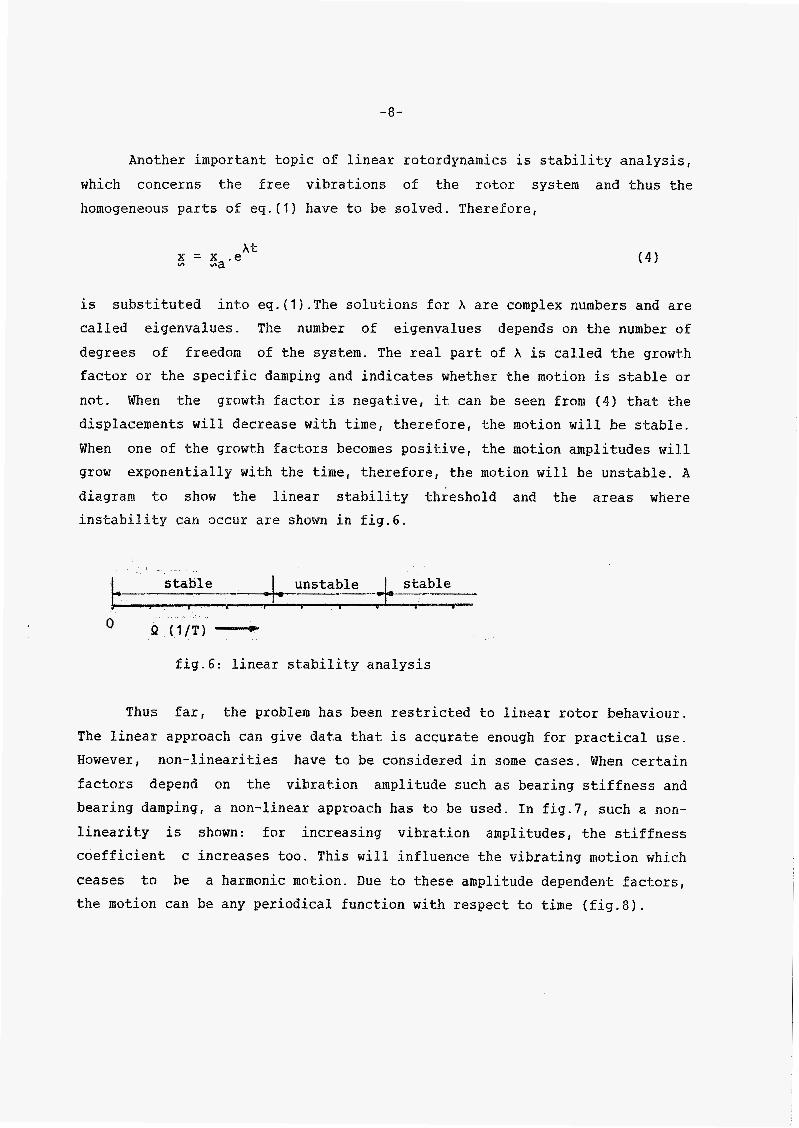
Another important topic of linear rotordynamics is stability analysis, which concerns the free vibrations of the rotor system and thus the homogeneous parts of eq.(l) have to be solved. Therefore,
At 5 = x .e ma (4)
is into eq.(l).The solutions for A are complex numbers and are called eigenvalues. The number of eigenvalues depends on the number of degrees of freedom of the system. The real part of A is called the growth factor or the specific damping and indicates whether the motion is stable or not. When the gr0wt.h factor is negative, it can be seen from 14) that the displacements will decrease with time, therefore, the motion will be stable. When one of the growth factors becomes positive, the motion amplitudes will grow exponentially with the time, therefore, the motion will be unstable. B diagram to show the linear stability threshold and the areas where instability can occur are shown in fig.6.
substituted
fig.6: linear stabi1it.y analysis
Thus far, the problem has been restricted to linear rotor behaviour. The linear approach can give data that is accurate enough for practical use. However, non-linearities have to be considered in some cases. When certain factors depend on the vibration amplitude such as bearing stiffness and bearing damping, a non-linear approach has to be used. In fig.7, such a non- linearity is shown: for increasing vibration amplitudes, the stiffness coefficient c increases too. This will influence the vibrating mokion which ceases to be a harmonic motion. Due to these amplitude dependent factors, the motion can be any periodical function with respect to time (fig.$).

A (mm) - & Y g i*v . I : non-linea stiffness characteristic
fig.8: linear and non-linear displacements vs. time
The unbalance response will change due to this non-linearity. A
typical non-linear unbalance response is shown in fig.9. In case of a non- linear approach, the value of the rotor speed at which a critical speed exists, depends upon the vibration amplitudeS.As can be seen from fig.9, the top values of the response curve move t o the right. This non-linearity can be observed when passing through a critical speed.If the rotor speed is increased from point O to point E, the vibration amplitude of the rotor response will follow the line ODABE. A sudden drop in the vibration amplitudes occurs at the transition from point A to point B. If the rotor speed is decreased from point E to point O, a sudden increase of the vibration amplitude occurs at the transition from point C to pint D. These Sudden changes in the vibration amplitudes are characteric of the non-linear behaviour of the rotor system.

t A
(m
fig.?O: nm-linear stability analyses
Also, in the stability analyses, non-linearities in the rotor system have to be considered. In the linear system, stable and unstable areas can be shown with a one-dimensional diagram. In the non-linear stability analyses, a multi-dimensional diagram will be needed depending on the number of amplitudes that influence the rotor motion. In fig.10, the dependency of the stable and the unstable areas of a non-linear system are shown on one of the vibration amplitudes.
Non-linear stability analysis can be performed by means of a pertur- bation technique. Stability can be determined by analysing the growth factor of perturbations on the motion of the rotor system. If this growth factor is negative, perturbation amplitudes will decrease and the motion will be stable. Stabilty maps (fig.10) can be drawn with the aid of this stability criterium .
the
in € i . g . í í , t h e response of a rotor system is shown. The stability map shows the unstable and the stable areas; On the lefthand side of (fig.lla)

-11-
fig.llb, the first critical speed can be observed. When the unstable area of fig. 1 la is reached, a sudden increase af the vibration amplitude can be seen, but passing through the unstable region causes the vibration amplitude drop until1 the amplitude level of the forced vibrations is reached. In fig. 1 l”, the whirl speed vs. rotor speed diagram is shown. If the rotor behaviour is determined by the forced vibrations, the rotor response is synchronous. Subsynchronous rotor vibrations can be seen in the linear unstable area.
When compared with the linear approach, the non-linear approach is more difficult and requirs more computational time; therefore, it should only be used for rotor behaviour that can not. be determined by the linear approach. This would be the case for self-oscillating vibrations or limit- cycles beyond the linear stability threshold. Also, the amplitude-dependent bearing stiffness and bearing damping can only be taken into account with a non-linear approach. Finally, the coupling between two rotor shafts will be mentioned because it can cause severe whirling which cannot be explained by
a linear analysis alone, since it. is probably caused by a non-linear in- teraction between the two shafts.
The rotordynamics terminology as discussed in this chapter is only a part of the entire rotordynamic theory. More complete introductions are found in the books of e.g. Loewy of Piarulli E401 and Gasch und Pfutzner
~ 4 1 1 .

4 0 - JL-
BI v i b ï a t i û n amplitude vs. rotorspeed
4
3
t 2 I
w 1
í 1 /TI
2 n (1/T) - 3 4
C ) whirl speed vs. rotorspeed
fig.11: non-linear behaviour o f a rotor system

-13-
3.Literature survey
Rotordynamics literature mainly deals with the different influences on a complete rotorsystem that will determine the vibrational behaviour of the rotor. These influences can be divided into four main aspects: 1 ) . Fluid and gas influences that act directly upon the rotor via bearings,
seals and working fluids. 2). Internal rotor influences, such as the rotor geometry, internal damping
and stress-strain relationships. 3). The influence of other rotor systems, such as the effect of torsion,
axial Forces, elastic-couplings and gearing. 4).The influence of the foundation and rotor casing. These four aspects do not cover the rotordynamic literature entirely, because other aspects such as balancing procedures, are omitted deliberately in order to restrict the investigations to those aspects that influence the rotor motion directly. In the first part of this chapter, each of the above four aspects are discussed; whilst the many calculation methods that may be used in the field of rot.ordynamics are discussed later.
3.1. Bearings
In rotordynamics literature, muck attention is paid to gas or liquid lubricated bearings; the advantages of these bearings (damping properties and low wear) often dominate the disadvantages (complicated structure and uncertain shaft position at the bearing location). In bearing technology literature, the position of the shaft centre at the bearing location with respect to the fixed bearing journal is often described by a distance, the eccentricity, and by an angle, the attitude angle. When the eccentricity and/or the attitude angle change as a function of time, the so-called dynamic behaviour of the bearing h a s to be considered. Rotation of the shaft centre with respect to the bearing housing is referred to as oil whirl. The usual method for describing dynamic bearing Uehiavioür is w i t h stiffness an6 Uampinïj coefficients. When considering lateral vibrations only, the axial coordinate can be disregarded and the

-14-
position of the shaft centre at the bearing location should be described instead, with four coordinat.es: two lateral and two rotational displacements perpendicular to the shaft centre line. The linear constitutive equation €or the bearing can be given now by a 4*4 stiffness matrix and a 4*4 damping matrix. In general cases, moments and rotational displacements can be disregarded, usually, so that for both the stiffness and the damping, they reduce to 2*2 matrices. The eight remaining coefficients will depend on the position still and t.he velocity of the shaft centre at the bearing location with respect to the fixed bearing journal. For high rotor speeds and low bearing loads, the bearing tends t o become unstable. This instability can be seen from whirling of the shaft with a
speed equal to half the rotor speed which is caused by strong cross-coupling effects (a force can cause a displacement perpendicular to the direction of
the force) and it is called a jw-whirl. One of the first authors who recog- nized bearing inst.ability was Newkirk [I] and he called it oil-whip. A good factual explanation of this instability is given by Crandall [2] .
The eight bearing coefficients can be determined from experimental data, or from analytical and numerical calculations. Clienecke [ 3 ] determined the coefficients by measuring displacements due to small lateral load variations with a special test rig. Mordman and SchOlhorn [4f used a modern FFT tech- nique and Bannister and Tawfik [ S ] developed a method whereby the bearing coefficients can be measured whilst the machine is operating under normal conditions. Analytically, only bearing coefficients for journal bearings have been obtained. Calculations that are based on the finite element method (FEP!), or the finite difference method (FDM), apply to all types o€
bearings. Reinhoudt [ 6 ] determined bearing coefficients in his doctoral dissertation using the finite element method.
1
3.2. Squeeze film damper
A squeeze film damper is in effect a journal bearing in which the inner mem- ber does not rotate [7]. It is used as a damping element between the bearing and the housing in order to reduce the level of vibration and the transmitted forces to acceptable values. Non-linear phenomena arising from these dampers such as subsynchronous whirling and jumping have to be avoided.

-15-
3 . 3 . Seals
Seals in rot.ating machinery influence the st.ability behaviour considerably and is difficult to find an equation that describes the wide variety of the non-linear dynamic characteristics. Oft.en an equation similar to that for the bearing can be proposed in which the cross coupling coefficients produce unstable behaviour. Most invest.igations have been concerned with determining the characteristics of labyrinth seals. Childs [e] dealt with annular seals in several articles. The influence of high pressure oil-ring seals on the response and stability of turbo compressors was investigated by Fleming [ S I .
it
3 . 4 . Fluid forces
Some of the rotor behaviour is determined by the surface and frictional forces between the fluid and the rotor. In pumps, the significant influences can be treated in the same way as for seals. Black [ I O ] paid attention to the equations for centrifugal machinery. In these machines, a residual lateral force due to asymmetry of the inlet and outlet nozzles has to be taken into account.
3.5. General influences
Rotor behaviour is infiuenced by the properties of the rotor and two very important properties are rotor assymetry and internal damping; they will be discussed in the next. two sections. Here, attention will be paid to the other influences . The effect of rotary inertia and the gyroscopic effect are often confused; the first is proportional to the transverse rotational velocities of the rotor system and is felt whether the shaft did rotate or not. The gyroscopic effect can be felt only during rotation and it is proportional t o the rotor speed. Other gyroscopic influences on the equations of motion were explained by Maller E l l ] .
When the diameter of the shaft is large relative to its length, deflections due to transverse shear become important. Tile influence of this factor on

-16-
rotor behaviour was investigated by Dimentberg [ 121. The shaft equation including transverse shear was first developed by Timoshenko [13] .
Rotor asymmetry
Factors that cause asymmetry in a rotar system relate to the shaft, the moment of inertia of the rotor and the gearing. The effect of each of these factors and any combination o f factors is important. One of the early contributions to the investigations of asymmetric shafts and asymmetric sup- ports was made by Smith [14]. When a system cont.aining one of the three fac- tors that cause asymmetry is investigated, the equations of motion can be written as a set of linear differential equations with constant coefficients for either a fixed or a rotating set-up. Yamamoto [ I S ] paid much attention to this kind of problem in the late sixties. The combination of two factors that cause asymmetry in both a fixed and a rotating set-up for a rotor sys-
tem requires a set of linear differential equations with periodic coefficients. The formulation of t.his problem numerically is still a subject for investigation. The addition of asymmetry with respect to both a fixed and a rotating set.-up multiplies the number of critical speeds by a factor of four. A study dealing with all these three factors was made by Iwatsubo
[ ' i61. Tnvestigat.ions of instability with asymmetric shafts in combinat.ion with in- ternal damping were made by Yamamoto [ IS ] and Ariaratnam [17] . Ariaratnam showed that the presence of external damping narrowed the region of instability that was associated with shaft asymmetry and it was confirmed by Tondl [18] .
A factual explanation of the instability mechanism is given by Crandall
~ 1 9 1 .
-17-
Internal damping
Damping rotating parts is usually called internal damping, because it is caused by friction within the rotor parts, both structural friction and damping in the material. It can be assumed that about 90% of all damping is due to structural damping. The amount of damping depends on the vibration amplitudes, the rotor speed, the temperature, the rotor geometry parameters, the material properties, the rotor displacements and time derivatives. Damping is a phenomenon that. is difficult to describe and, usually, linearized models have to be used. This has two advantages: the linear equations fit bett.er into the existing equations for rotor and the parameter values of the damping model are easier to meaure. Internal damping can lead t o instability and a practical explanation of the mechanism of this instability is given by Crandall [ZO]. Among the first in- vestigators who recognized that internal damping could lead to instability were Kimball [Zl] and Newkirk Cl]. They investigated the threshold of unstable motion due to internal damping and determined that the main cause was friction between the rotating parts. Gunter [22] investigated the influence of flexibility in an asymmetric support and concluded that increased asymmetry could delay the instability threshold. Tondl [I81 con- sidered all kinds of non-linear damping equations and investigated their influence on the stability regions of a simple rotor system. It is necessary to use a non-linear damping equation when explaining why the shaft sometimes has to vibrate with a certain degree of intensity before a subsynchronous whirl is induced. For example, Muszynska [23] studied a non-linear damping model.
shaft
Axial force, torque, couplings and gears
Investigating the influence of axial forces and torque on the behaviour of a rotor started before 1900 but, due to the complexity of the subject it is not yet complete. Eshleman and Eubanks [24] showed that the influence o f a
torque is significant for very slender supports. Torque fluct.uation may lead to torsional vibrat.ions. This fluctuation can be produced by induction in synchronous machines, o+ by Eooke joints. h'ooke
joints can be used to overcome a misalignment bekween two shafts. Rosenberg
-18-
[25 ] showed that this problem for a simple shaft can be transformed into the standard Mathieu equat.ion. In some cases, entire gear systems were investigated and different methods of calculation for such systems were proposed.
Coupled bending and torsional vibrations
Bending and torsional vibrations are coupled when the vibration amplitudes are not. zero. Basically, their interaction is non-linear. Although the coupling may be weak, this phenomenon has to be considered when the critical frequencies for the bending and torsional motions fall into the same region. The coupling can induce an additional instability which produces a non- synchronous whirl. In this situation, the whirl speed will be half of that of the rotor speed. In his book, Tondl [ I S ] gives some analytical results for .the instability region. A queskion that. is still not entirely solved is whether the coupled vibration can have a significant effect on rotor behaviour or not? On one hand, [ 26 ] stated that the resonance due to the coupling will not be dangerous but, an the other hand, it is known that subsynchronous whirl induces bearing instability.
Kellenberger
Exceeding a critical speed
The of a driving unit needed for passing through a critical speed depends the rotor behaviour during the transition and both internal and ext.erna1 damping will play an important role. The influence of damping on the passage through a critical speed was investigated by Dimentberg C.121.
capacity on
Foundation
Until now, only linear rotor-bearing-foundation systems have been inves- tigated and these investigations mainly concerned the influence of support flexibility and its asymmetry on the rotor behaviour. Stecco and Pinzautti [27 ] investigated the influence of casing stiffnesses on rotor behaviour. A complete rotor system can be divided into finite elements, however, the num- ber of finite elements has to be restricted to comply with the computer

-19-
capacity. Kramer [28 ] used a modal analysis method and so did Jäcker [ 2 9 ]
who calculated forced responses and stability regions for large rotor- bearing foundations. A s mentioned before, Gunther [22 ] determined the influence of asymmetric support flexibility on the stability threshold of a rotor system with internal damping. Come interesting results for the behaviour of large rotor-bearing foundations appeared in the bulletin of the conference on "Rotordynamica Problems in Power Plants" held in Rome, Italy from Sept. 28 - Oct. 1, 1982.
Calculation methods
During the last ten years, much effort has been put into the development of methods for solving rotordynamic problems. This has been possible because powerful digital computers are available €or using different solution procedures. Nowadays, programs for large linear systems are generally available to the invest.igat.ors of rotordynamics. Before computers were used, the calculation methods had to be relative simple, but these methods can be used still by designers. The early methods were developed to determine the first critical speed of simple rotors. Both the "Rayleigh method" and the "Dunkeley formulaes" were developed before 1900. In 1922, Kolzer introduced a method that could calculate the critical frequency of the torsional motion of any rotor. This method is based on a rotor model which is considered to comprise a number of individual beams. For each, a relationship between the dynamic parameters o€ the two ends were derived. With a starting value for the rotor speed, the relationship between the dynamic parameters at the ends of the rotor can be determined. Generally, all constraints but one can be satisfied. By means of an iterative process, the critical rotor speed that satisfies all constraints can be found. An extension of Holzer's method was used by Myklestadt and Prah1 for calculating the critical speed of the bending motion. Land [30] ,
E311 adapted the method for calculating complex eigenvalues and forced responses. His contributions made the method into a useful tool for rotor- dynamics and this method is known as the transfer-matrix method. It was shown by Chen [32 ] and Kirk and Gunther [33 ] that this method could be used for non-linear analysis, as weïi.

-20-
Another trend observed in methods used for calculations in rotordynamics is based on energy principles. Again, the rotor is divided into a number of elements. From the equations of motion for each element, a complete set of equations of motion for the entire system can be produced and solved numerically. This method is called "the finite element method". A finite element for the purposes of rotordynamics was first considered by Ruhl and Booker [34]. Nelson [ 3 5 ] published a number of articles that introduced elements with gyroscopic effects, including transverse shear and with inter- nal damping. Using the first eigenmodes of the system, the number of degrees of freedom for the finit.e element equation can be reduced and this method is called the "modal@' method. With the modal method, forced vibration problems and transient. rotor analysis can be considered in an effective way. Transient calculations for complete rotor systems were made by Adams [ 3 6 ] ;
but non-linear calculations of rotor systems mainly concern the non-linear bearing characteristics. The authors mentioned above IShen, Kirk and Cunter, Holmes, Adams) restricted theirselves to this non-linearity in their numerical calculations. The methods used to investigate the stability o f
non-linear rotar sysS.ems are restricted to the perturbation technique and the Galerkin method. In analytical calculations, these are often used in combination with the Routh-I3urwit.z cri-keriurn. Examples o f such calculations can be found in Tondl [ l a ] , Pedersen [ 3 7 ] and Dimaroyonas [ 3 8 ] .

-21-
4 . Subjects for further investisation
In this section, some subjects for further investigation are considered. * Non-linear foundation influences. It was mentioned in the section about foundation influences, that only linear foundation influences have been taken int.0 account until now. In several cases, non-linear influences due to large base rotations and translations do play an important. role. Langelaan E391 investigated the influence the suspension of a washing machine on the equation of motion for a rigid rotor on rigid bearings. Large base rotations and translations of the rotor were allowed. Other examples of such systems include all kinds of port.able machines that contain rotating parts. In these systems, large base rotations and translations exist. A shaft equation which includes these large rotational and translational motions has t o be formed for developing these calculations. * Coupling between t.wo rotor systems.
Several have been performed to study the influence of misalignment of the coupling between two rotors, or of the parameters of the coupling itself. However, the behaviour of the coupled system depends not only on the coupling parameters, but on the characteristics o f the coupled rotors too. These non-linear rotor characteristics have to be investigated probably in order to avoid other kinds of instability. * Damping. Damping of rotors is an important factor in the determination of the amplitude level of rotor vibrations; however, it is rather unpredictable. Damping depends on many factors, but the influence of these factors is usually linearized or assumed to be constant. All linear and non-linear dam- ping equations must be considered in order to find better methods of prediction. The influence of damping on rotor instability and sub-
synchronouos whirling have to be analyzed. * Rotor asymmetry. Asymmetric rotor models can be investigated analytically quite well, but it is that asymmetry with respect to both a fixed and a rotating set-up produces equations of motion with time variable coefficients. This makes it difficult t o formulate a general finite element for the rotor shaft that
of
studies
known

-22-
includes rotor asymmetry and f urt.her . * Modelling transient fluids in A lot of experimental work
of such an element should be investiyated
rotating machinery. for determining the influence of fluids on
rotating machinery has been done, but. the complexity of the system and the different types of numerical calculations involved made it essential for the system t o be simple. New and better numerical models should be developed. Models that are based upon modern numerical techniques can be used for reducing the comp1exit.y of systems and solving the resultant differential equations.
Although many other aspect-s deserve further investigation such as numerical balancing procedures, seal modes, bearings etc., they will not be discussed here.
References
C l 1
c21
i31
c41
csi
Newkirk, B.L., “Shaft whipping” Gen. Elec. Rev. 27, 169-178 (1924)
Crandall, C.H., Heuristic explanation of journal bearing instability, NASA CP 2250, Rotordynamic Instability problems in high performance turbomachinery, may, 1982.
Glienecke, J., “Feder- und Dampfungskonstanten von Gleitlagern für Turbomaschinen und deren Einfuss auf das Schwingungsverhalten eines einfachen Rotors“, Dissertation T.H. Karlsruhe (1966).
Nosdman, R. and Schollhorn, K., Ermittlung der Feder- und Dampfungskonstanten von Gleitlagern durch Parametrische Identifikation VDI-Berichte, Nr. 381, 1980.
Bannister, R.H., Tawfik, A . R . , The determinat.ion of the hydrodynamic oii film force coefficients by i f i - s i t ü tectiny , C::nferer,ce ~n
“Rotordynamic problems in Power Plants“, sept.-oct. 1982, Italy.

-23-
[6] Reindhoudt, J . P . , On the stability of rotor- and bearing systems and on t.he calculation of sliding bearings, PhD dissertation, T.H. Einhnven 1972.
[7 ] Holmes, R., Squeeze-film damping of rotordynamic systems, Shock and vibration digest, sept. 1980, pp- 17-15.
[ S I Childs, D . W . , Dressman, J.B., Testing of turbulent seals for rotor- dynamic coefficients. NASA-CP 2250, May 1982, pp. 157-171.
[ 9 ] Fleming, D.P., Damping in ring seals for compressible fluids, NACA-CP 213.3, may 1980, pp. 169-188.
[ l o ] Black, H.F., Calculation of forced whirling and st.ability of centrifugal pump rotor systems, ASME Paper no. 73 - DET - 1.31 ( 1 9 7 3 ) .
[ll] Müller, P.C., Stabilität und Natrizen, Springer Verlag, 1977.
[12 ] Dimentberg, F.M., Flexural vibrations of rotating Butterworths , London , 196 1 .
shafts i
[ l 3 ] Timoshenko, S . , Collected Papers, McGraw-Hill, New York, 1954, p. XT.
[ i 4 1 Smith, D.M., The motion of a Rotor Carried by Flexible Shaft in Flexible Bearings, Proc. Roy. Soc. (A) 142, 92, ( 1 9 3 3 ) .
[ 151 Yamamoto, T. , Ota, H. , On the vibrations of the shaft carrying an asymmetrical rotating body, Bull. ISME, no. 6 vo. 21, Feb. 1963, p. 2 9 .
[ 16 ] Iwatcubo, T., Stability of rotorsystems having asymmetric elements, Ing. Arch., no. 47, 1978, p. 293.
[17] Ariaratnam, S.T., The vibration of unsymmetrical rotating shafts, ACME winter Annual Weeting, Nou. 29 - k c . 4 , Taper 64 ~ W A t n I clz??-I- 4 ~

-24-
[ 1 8 1 Tondl , A. , Some Problems of Rotor dynamics , London, Chapman and Half i r , td . , 1965.
[ 1 9 ] Crandall, S.H., The physical insight of rotor instabilities, Rotordynamical instabilities , AMD vol. 55, ASME, New York, 1983, pp. 1-18.
E201 Crandall, S.H., Physical explanation of the destabilizing effect of damping in rotating parts, NASA CP 2133, Rotordynamic Instability problems in High Performance Turhomachinery, May 1980, pp. 369-382.
E211 Kimball, A.L., Internal friction as a cause of shaft whirling, Phil. Mag., 49, 1925, pp. 724-727.
1221 Gunter, E.J. jr., Trumpler, P.R., The influence of internal friction on the stability of high speed rotors with anisotropic supports, ACME, Journ. of Eng.F.Ind., nov. 1969, pp. 1105-1113.
[23 ] Nuszynska, A . , "On motion of a horizontal rotor with non-linear elas- tic and internal damping properties, Non-linear vib. prob., 12, 1971,
p. 309.
1241 Eshleman, R - . L . , Euhanks, R . A . , On the critical speeds of a continuous rotor, ASME, Journal of Eng. E'. Ind., nov. 1969, pp. 1180-1188.
by universal 1958, pp. 47-5
[25] Rosenberg, R.M., On the dynamical behaviour of rotating shafts driven (Hooke) couplings, ASME, Journal of Appl, Mech. , mar.
E261 Kellenherger, Welle-Kopplung 117-121.
W., Erzwungene Komhinationsresonanzen der rotierenden von Biegung und Torsion, Brown Boveri Mitt. 1980, pp.
[ 2 7 ] Stecco, S . S . ,
turbomachinery Pinzauti, M., On the influence of casing stiffness in vibrâtirjiì âna?i.'sis, Proc. ::f the Iiist. af Mech. E n g . ,
London, C 271/80, 1980.

-25-
[28] Kramer , E . , Computa t ion of vibrations of t h e c o u p l e d system machine -
f o u n d a t i o n , Proc. of t h e I n s t . of Mech. Eng . London, C 300/80, 1980.
[29] Jäcker, M . , V i b r a t i o n analysis o f large rotor-bear ing-foundat ion-sys-
tems u s i n g a model c o n d e n s a t i o n fo r t h e r e d u c t i o n of unknowns, C o n f .
P u b l . 1980-4, Mech. Eng. P u b l . L t d . for t h e I n s t . o f Mech. E n g . ,
London, C 280/80, 1980.
[30] Lund, J.W., O r c u t t , F . K . , C a l c u l a t i o n s and e x p e r i m e n t s on t h e un-
balance r e s p o n s of a f lex ib le rotor, ASME, Journ. of Eng. F. I n d . , V o l . 89, no. 4, nov. 1967, pp. 785-796.
1311 Lund, J.W., S t a b i l i t y and damped cr i t ical s p e e d s of a f l e x i b l e rotor
i n f l u i d - f i l m bearings, ACME, J o u r n a l of Eng. F. I n d . , V o l . 96, no. 2, may 1974 , p p - 509-517 .
[32] Chen, F . A . , T r a n s i e n t f lexible-rotor dynamics analysis, Part 1 - T h e o r y , J o u r n a l o f Eng. F. Ind . , May 1 9 7 2 , pp. 531-538.
[33] K i r k , R.G., G u n t e r , E.J., T r a n s i e n t r e s p o n s e of rotor-bearing-systems, ASME, J o u r n a l of Eng. F. Ind. , may 1974 , pp- 682-693.
[ 3 4 ] R u h l , R.L., B o o k e r , J.F., A f i n i t e l e m e n t model for d i s t r i b u t e d
parameter t u r b o r o t o r systems, ASME, Jousna l of Efig. F. I n d . , feb.
1 9 7 2 , pp. 126-132.
[35] Relson, H.D., McVaugh, J . M . , The dynamics o f rotor-bearing systems
u s i n g f i n i t e e l e m e n t s , ASME, J o u r n a l of Eng. F. Ind., may 1976, pp.
593-600.
[ 3 6 ] Adams, M.L., N o n l i n e a r d y n a m i c s of m u l t i - b e a r i n g f l e x i b l e rotors, J o u r n a l of Sound and V . Z . , vol . 7 1 , no. I, 1980, pp, 129-144.
[ 3 7 ] Pedersen, P . T . , On t h e self excited w h i r l o f rotorsr I n g . A r c h . , V. 42, iY73 , pp. 267-284.

-26-
E381 Dimarogonas, A.D. , A general method for stability analysis of rotating shafts, Tng. Arch., vol. 44, 1975, pp. 9-20.
[39] Langelaan, F., The dynamic behaviour o f a system consisting of a rigid rotor and a rigid body suspended in springs, MSc Thesis, T.H. Eindhoven, july 1981, (in Dut.ch).
Further litesature
[40 ] Loewy, R.G., Vincent, J.P., Dynamics of ftotakincy Shafts, The shock and vibration information center, naval research laboratory, Washington D.C., 1969.
1411 Gasch, R., Pfutzner, H., Rotordynamik, Berlin, Heidelberg, New York, Spinger, 1975.