digitool.library.mcgill.cadigitool.library.mcgill.ca/thesisfile64570.pdf · 1 " 1 ( '. Il , b " ,;...
212
il. .... ... .. ... ,1 ...... • ........... .... .. ! \ '1 o ! " \ ( .' . CDlAC'rDIS'fiCS or ZIICOlfIDII TI'tUaILOUDE '1'BBIMAJ. lt.A.sHd . A ft P"'!OTIS Z. B. Se. Departllea.t of Chemical Engineermg 1 HcGUl University Under the Superv1siou of Dr. W.H. Gauv:ln ·Subl11tted to the Faculty of Graduate Studies and Reaearch of McGUl University in partial fulf:U.ment of the requirements for the . degree of of Engineering " Itr HcGUl University .. lI>NTR!AL. Canada 1 Ausu:8t 1983 \f) - 1 .. ;. .... .. , . ,. .... \ 'J' 0 0' , ( <:l " , • \ :' ... ,1 f . , 1 f , , ! f ': l' r 1· ' ! 1 1 1 , 1 l , ! 1 i .1 1 j
Transcript of digitool.library.mcgill.cadigitool.library.mcgill.ca/thesisfile64570.pdf · 1 " 1 ( '. Il , b " ,;...

il.
~._ .... ~ ... ,-~_... .."'"'~_ .. _.--~~~" ... ,1 ...... "'~.-." • .-..~ ........... -~ .... ~ ~~~r .. ".-"-~,,
!
\
'1
o
!
"
\
(
.'
. CDlAC'rDIS'fiCS or ZIICOlfIDII TI'tUaILOUDE
'1'BBIMAJ. lt.A.sHd
. A
}~IS ft
P"'!OTIS Z. SPn.IOTOPOULO~ B. Se.
Departllea.t of Chemical Engineermg
1 HcGUl University
Under the Superv1siou of Dr. W.H. Gauv:ln
·Subl11tted to the Faculty of Graduate Studies and Reaearch of McGUl University in partial
fulf:U.ment of the requirements for the . degree of ~ster of Engineering
"
Itr
HcGUl University .. lI>NTR!AL. Canada 1 Ausu:8t 1983 \f)
- 1
.. ;. .... .. , .
,.
....
\
~
'J' 0
0' ,
(
<:l
"
,
•
\
:'
...
,1
f
. , 1
f
, ,
! f
': l' r 1· ' !
1 1 1 , 1 l , ! 1
i .1
1
j

,
" .
..
• ".
'1
- ..
'. ,
..
~STICS or' ZiRcONIUM, TETRACBLORIDB
TBDKAL PWMAS ..
Il
\
~
'.,
."
....
o ., •
f 1 j
• i )
f , ! ! r
,
..
l,

..
" ,. "
(
..
. ""
L
.....
. ,
\ .
• >
'-
l 1
f !
,To' My Beat Fr1'eRd.
(
-"0-'"
My W1f.~
~
1 l j , ~ j
}
1
..

1 " 1
(
'.
Il , b
"
,; l,
.. \\1 j'
l, ::
\1
. . ABSTRACT
This project deals ~th a novel application'of pla~ .
teehnology. A reproducible ZrCl4
transferred-arc pla~ wes Q
8uecessfully generated between a fluid convective cathode and a . .
g
IIlOlten zirconium" anode, using vapours of sublimed zrCl4
as the
feed material, in a specially-designed experimental system. The
operating characteristics of this arc vere expertmentally studied ~ r/ V
and compared ta those of pure argon. The total power used to Q
lenerate the pure ZrC14
plasma, within the operating conditions • ~ fi
us.d in this ~tudy, varied fram 10.2 kW to 30.2 kW, and was more ..
, . than twiee the power·required by pure argon arcs. 'It was_observed
that for the range of Z:C14 fee~ rates studied. the power inereasad
almost linenly vith an increase in feed rate. The arc voltage ~
, inereased s1gnificantly with are length, while 1t8 dependence on
are 'current was minor.
The fraction of the input energy tr&nsferred to the.
anode" for the range of ZrC14
feed rat88 studied, deer .. 1sed
alaost linearly"with an increas. in feed rate. Arc leogth _.
...
x
..
j
j J !
i 1 { ~
j~ ;8 , , }
QI î ....
. , j . 1 ,
" 1
(
1 .' !
r ! , 1
·1
1

r
/
, the major factor in the dist,r;lbution of the arc energy. With·
tnc:reasing arc 1ebgth, the fraction of enell"gy transferred t.o
the anode decreased.
The percent conversions of the meta! co11ected in the
molten zirçon~um anode varied between S,and 16.7%, and depended
atrongly on the stabi1ity of the arc.
.'"
. ,
G
....
..
r
"
. i , ,

'.
' ..
l'
..
.. • •
Le projet pré$enté dans ,cette thèse constitue une
nouvell,e application de la teclmologie des plasmas. On a réussit
-à ét~blir un plasma de vapeur de ZrC14
en générant un arc transféré -
" entre une cathode et une SIiode de zircOnium fondu dans utJ système,
spécialement conçu. L'alimentation consistait de vapeur produite
par la sublbnation de ZrC14. Les caracteristiques opérationnelles
ont été étudiées experfmentalement et c~mparées avec celles d'un
plasma d'argon. La puissance totale requise allait de 10.2 kW à ' (\
30.2 kW dépendant des conditions utilisées, et étsit plus de deux
foi. plus élev~&..> que celle tr.equise par un plasma d'argon.
Il fut observé que pour les taux d r alimentation observé, "" .
la puissance requise 811IPDentait linéairement avec le taux
d'alimentation. La tension augmentait fortement avec la lOngueur
d'arc, et beaucoup moins avec le courant.
ta fraction de 1 '~nergie totale de l'arc, transférée 1
l' &Docte décroissait d'une façon linéaire avec" ùn accroisaemeht·
1 - j
t
,j
...

','
(! •
,
-
, du taux d'alimentation. La longueur d' arc ~tait le facteur
principal dans la distribution de l'énergie dails le réac);eur. En
accroissant - la lon<gueur: de l' ar,c, la fraction de l'énergie
transférée a l'anode décroissait;
La fraction du métal déposé dans l'anode variait entre
S et 16.7% du zirconium contenu dans l'alimentation et dépendait
fort:ement de la 8tabUit~ de l'arc. O'
"' .
. . \. ' .,
< ...
, . \
Il
1 "

,1
a
'.
..
:
(
,.
r
... ...
...
The author nshes to express his gratitude to all 'tho.e'
wbo contrlbuted to tbe work presented in . this thesis.
To Dr. Hyun K: Choi, a special thanks 'an,d a distinct
aclm.owledgement for bis valuable contribution to the design,
construction and operation of the equipment.
To "the members of the Plasma Teclmology Group, :ln
pattieular Prof essor R.J. Mtmz, Dr. M.T. Mehmetoglu, Kr. A. • '\ 0
Kyriacou, Mr. P. Grosdidier and MS. M.-P. Amelôt.
To the Che.adcal Engineering Workshop staff, Kr. Berbert
Alexander, Kr. Allain .Ga'gnon. Ml'. Walter Greenland and -Kr. A.
Jtr18h.
Special thanks to M'r. J.B. Dumont of the Ch_ieal",
Engineering Stores.
. To the staff of the Noranda Research Centre who
-, /---eontribut~ to the construction of vari~s equ_,~pDlent an~,erf~d
the c:he!IIl1cal analya1s of the product. . ~ / /
, ...
- ,
-4 ,
...
•
;
(/).. .. ..- ,
~
1 1 .. . -i
)',
l J l l
i
" " " 1 1
~~ . , ,
'(

(
...
, .. • ..
. '
.. '. f' ~
II
To Kra • Heather Avede~ian for her exc~11ent bYP1ng ôf.
. thu thesis" and to Krs. Janice poltr1ck-Donato f~r "thè' ........
prepa:w;ation of the drawings.
Finally, to ~he author' s famlly' for their under~and:1Dg;
patiesu:e and encouragément, 'and to his fr.i~S who st.o,?d ,by him
thraugh the rough times. , .
.1
j.
"
r •
, y
\
..
cr
.. ~
• 1
" \
)
.'
..
" ,\
(J~ __
"
"
, .
./ ..
" ,~

(
(
, ,
TABLE OF COsr.!RTS , .
,7 ABSTRACT 1 ,
~ ~
RESUME
~ACKNOWLEDGEMENTS \-" , ~
",,-
" .
.. ...... TABLE OF.tONTENTS
0
LIST O'F FIGURES
LIST OF TABLES
GENERAL INTRODUCTION
GENERAL INTRODUCTION"
o
r L:ITERATURE REVIEW
INTRODUCTION' ,. ~
1. ZDtCONIUK METAL. PIOPERTIES AND PRODUCTION
ZIllCONIUH AND ITS USES
OCCURRENCE OF ZIllCON:IUM . \, .,
ZIllCOJJIUH PRODUCTION ME'IHODS
2. PLASMA PHENOMBNA AND PLASHÀ DEntES
-'
DEFIN:ITION OF PLASMA .., PLASMA DrneES
<> • •
1. Eleetrodele88 Plasma GeDeratora
\ . .
,-
. ..
1
" 3
4 ... 4-
S
8 ,1;
9
19
19
19 6
21
.. . 21

(
,. . -{}
"
u. Arc Pl .... Ç>
a. D.C« Jet Arc Pl .... ... ~'" -": ~_.- .. " !
: b.. Tran8,f.,erred-Arc P1.-_
U1 • Uectric Putur .. of Arc Pla ....
. HftALLUl.GICAL 'APPL~TtoNS O~ ~TEN' ANODES ~ .. - '': to6t ' •• _ ..
\;~.,o ...
l'LASMA. APPLICATIONS
3.. THE PLAS!IÀ PRODUCTION OF ZIllCOHIUH METAL
TIll PLASIIA PRODUCTION OP ZIICOrmJK FROH ITS JW.mzs
TlΠ~LASHl PRODUCTION OP ZIltCOHIUM FROH zr02
, . " ~ 'llEDUCTION or iŒut. BALmES TO THE ". , 'HBnL oit LOWER ,SALmIS •
CONCLUS10NS . DftUNCllS'
IlI'DODOC'rION .
~
~I~,OP,~ .. ~ 1. Pover' Suppl,. .
• .... ;:f-
2. éOlltro~ Couol..
3. Cu -and Vater· nov Iut.~tat:I.eD 4~~ Arlon auter . \ .
\ s. Subl~r S1st_
,. i. ,SubUJler v ... ü
'. .: 11. SubU.aer IuulatiOll ad Beater
6. Z~14 ad Arlon ' __ ediDa Lin .. .. _.' CI
!~
~
, , .. '24'-"0 ~
24
34
40
41
Sl
S5
58
...
67
79
~ ~
~
,
84" :
84
85
86
86
'91
92
..
" . -
i ! ,
'~ \
l ,,' ,t((t, t ! 1 i . . , i l
1 j . , 1 1 1
t
, ;

'- ;
~ •• I" • • "
""---
'- 7. Cathode Aa.ably
8. . Anode Aas_b1y
10. Ezbaust: Gas Coud.ser
il. The Chlorine Absorber and Bood
~ TECHNIQUES AND INSTRUMENTATION'
"- ,,,,1.. _.Keaturseo.t of Arc. Voltage ... -..... ...... ~ "-or ... -." ~ -,.", .
2. C~or1aetric Mea~ __ tà ~. - .
3. T_pérature r.otheras on· 'the Molt_ ADode ~ ,
4. Arc GeoIIetry
s. ~ytieal Techniques and Equi.-m-tt"
UPElDŒNTAL PRocEDURE
l'. ExperiaeDtal ltun Preparatioa
2. Peecl PreparatioD
3. Preparatiop of the Arc Stan-up .. ~
4. Pl.u-.a Start-up and apérat10a
s. SbutdowD
6. Dat~rtOD of ZrC14 Peel
7.. Waty 'Mu8Ufta '
,8. Ca11bratioll lletbod. ..,..
"
."
1 •
'. 1. calibratioa. of the ArIOD Iot:~ .. s
11. Ist1aatioD of leeeJ lata >,:
USULTS AIq) DIscussrOR
!Jl .' GfDeral" ObservattoGa
.rotal Arc Voltage
.' " /. 1
_ .. ~
"
, .... - --<8" t ...
\ .
94-
98
101
104
106
107
, 1()7
108
1'~"-l'08-"
109
110
lU
lU
113
114
11S
117
118
119
119
120.
126
U7
132
:
..
\
0, ,
<Ji
, ~.
, " t ..
"
1 " -(
(
. ,
-.
, i. ' Î 1 , , '
, '

(
<
\
-.) OveraU Anode ED.ergy Tranaf er
' .. '''''.
HOlteD Bath Teaper~ture
Production of Z1rcOQ:1uII Hetal
• 1
l'-
,~~I~HS AND',~IOBS AElFl1U!œcE:S
,. '"
. .
~mpoICIS
APrBIIDU 1 tJi&Itlè)DlJWI;[C PllOPDTIES or ZncotmJH BALInES
nQJU-t"l .' BlAT 01' UACTION (AB) POil TB! DISSOCIAtION
. or ZIICORtUH T!TlWW.mES AS A rmtCTIOtt or TIl! TEMPERATUllE
rlGDll! 1-2 nu !HEllGY CHANGE (AF) toa TB! DISSOCIA1'ION or ZDCONIUM T!TlWW.IDES AS le. roNCTION or TEMPERATURE •
fiGUU 1-3 LOèAaITBM OF THE EQUlLlUIUM CONSÙNT PO,,' TB!. DISSOCIATION OF ZIllCONl;UH TE'f1WW.IDBS AS A FURCTION OF TEKPEIATtJU
:-.. -..: ePaD1X Il: DPEIlDŒNTAL DATA
Il - 1. PUllE AllGOli PLAS!a
11 - 2. PUllE ZrCl~ PLASHA.
Il - 3. VOLTAGE AND PllACtiOR or POIIDo 'l'IAlfSlDll!D 1:0 ANQDE AS A l''ORCTIOII OP
l" • ,ZrCl~ FLOW BA1'E
APPaDUIll ~
•
('li, '
139
145
" 148
.149
154
..
. 'lA
4A \
SA .1
"-71.
)-
>.
"
-
, '~
, .
. ,
, l'
J i
i
i Î 1 1 \ 1
t
l. 1

'1lt. '
r 0
~I 7-. ' " . 1 - . ,
( " tIST OF FIGURES f - ?
, lIUMID " PAGE -LITDATURE RE1IEW
~ , :
-1-
1 THE COHV!NTIONAL DOLL PROCESS AS USID BY î 1
.. WAJl-cBANG AND PECHINEY, UGINE KUHLMAN 13 ' l • i , .. 1
2- VOLTAGE DISTRIBUTION ALONG THE ARC LENGtB 32 1
3 PARTIAL PRESSURE-VERsUS-TEMPERATURE -; 1
4.5 .. \
FOR A ZIRCONIUH-CHLORINE SYSTEM ' ,
î , . 1 4 PIlEE ENERGY OF ZIRCONIUM ltALIDES, l '
VERSUS TEMPERATURE 46 ' 1 . " .i' . , j .. r EXPERIMENTAL SECTION J
III 1 i
.. 1 PARTIAL PRESSURE-VERSUS-TEMPERATURE
POR A ZIRCONIUM-CHLORINE systEM 76 , l ,.,
SCBEMAT,IC DIAGRAM OF THE OVERALL SYSTEM 82
'1 2a
., .
2b PROTOGRAPH OF THE OVERALL SYSTEM 83 j . 1
3' 87 i
SCBEMATIC DIAGRAM OF THE ARGON HEATER · 1
4 S~IAGRAM OF THE SUBLIMER " as }-
$' ' S S SCBEMATIC DIAGRAM OF THE CATHODE A:'SSEMBLY 9S
6 SCBEMAtIC DIAGRAM OF THE ANODE 'ASSEMBLY ... 99 1 ~ , , . - .. !
7 SCBEMATIC DIAGRAM OF THE REACTOR SYSTEM 102 1 ! . 1
8 SCBEMATIC DIAÇRAM OF EXHAUST GAS CONDENSER lOS '> ! ; · ,
9 PROCESS SCHEMATIC DIAGRAM 112 1
io CHABACTEllISTIC VOLTÂGE-VERSUS-TIME EXPElUMEN'l'AL CURVE FORI PURE ZrC1
4 ~ il3
11 PHOTOGRAPHS OF PURE ARGON AND ZrC14 TllANSFERRED-ARC PLASMAS 128
(
, . . r -
~ , "
, ,
\ .-----

" '~q - ..
• LIST OF FIGURES
.. ' .
. ' -
..
(
..
, ,
1
1 • "
, j ;
1 , j
.. ,
f ! , r 1
1
1
1

" p
, •
( LIST OP TABLES
,NUMBEIl
EXPERIMENTAL SECTION •
I cALIBRATION OF ZrCllf. SUBLIMER .
.-
\
,.<
.,
(
..
" -
o
t
125
•
1 t~ J
1 1 J
l
r

(
l'
". '" ~\
~ .. "
/ >
1
....
~ •
GENERAL -------
..
".
,
"
-.
6 J
-
r

(
-,
.0
)
.~
GENERAL INTRODUCTION
The ~PPlica~ns of pl~sma technology to the fields of
high-temperature chemical and metallurgical processing have been
receiving increasing attention in recent yeara. The energy criais
and the rather unpredictable future have led Industry ta reevaluate
and fmprove their existing processes,'and to seek new energy
efficient alternatives. )plasmas' unique features of high energy
content a~d reactivity /ombined with a shift, by Industry, towar~ e1ectricity as a more ~table energy base, appears promiaing for
new developments in many high-temperature processes.
This study constitutes the second phase of an overa!l
effort ta demonstrate the technical feasibility of producing,
economically, dense zirconium metal of nuclear-grad~ continuously ~ g
fr~ dehafniated purified zirconium tetrachloride (ZrCl ), ustng a " '~o', 4
plasma system. If successful, this plasma system could replace
the last stage of the conventional Kroll process which involves
several highly energy-deœanding and labour intensive st~p8.
1
\
t
1 i .
..

..
(
"
2
, .
e Specifically, the last production stage, to couvert zirconium'
te,rachloride into zirconium metal sponge, contributes about 35% of - ,
the total operating cost of a conventional plant. o
The purpose of chis s~cond ph~e was to modify the
existing experimental system so that a transferred-arc plasma of
pure ZrCl4 could ,be generated, and to study the characteristics of
'. this plasma using a molten zirconium anode. Dehafniated ZrCl4 used
as the raw material 1a an important'!ntermediate in the final stàge
of ;he ex1st1ng Kroll process. ~
In accordance with the p~actice in the Plasma Laboratory;
this thesia ia preaented as a n~ber of individual sections, which
are complete in themselves. The two main sections are:
(i) Â review of the pertinent literature on the use of
zirconium meta~, existing and proposed methods for its production,
the use of plasma'technology ~or metal tetrahalide dec~position, and a general discussion of plasma types, plasma producing devices,
and plasma applications. o
. (~i) An experimental section with ~ detailed description
of the experimental system design and operating procedure, ~e
cbaracterization of pure zrCl4 plasma, and a preliminar: determination
of the collection of zirconium metal ta the molten anode. From this
experimental evidence, conclusions are presented and recommèhdations
for further work are offered.
..
...
. .
, , '
, , 1 \)
..
f t 1
1

~' . ,
+ for ..
,\
1
l
i ,
.(
.-
" " .;
:.-
If,
... ",
\ ... L ~
1" ..
1.!.!!!~!!!R!. !EYIEW
n ,.
..
." \

, .
-,'
l. .. INTRODUCTION
.. 3 t Th1a rev1.ew of the literature ia presentèd UDder th~ tuee
1Ia~ headiDgs: 1
10 Z1rcon11111 Hetal, Properties and produet1OnO
v> 2. 'Plasma Phenomerui and Plasma Devices '
3. The Pla~ Production of Zirconium Metal.
~
The first section 18 aimed at providing background
1Ïlfoxaetion on zirconium properties and its uses that malte it an
attractive metal to industry" In addirion., the oceurrènee of the
.. ta! and a -rev1ew of the conventional metnods of ,its production
are a1so d1.scussed.
\. Sinee a plasma device WBS used to generate the high-,~
t~erature heat source needed for the react10n to take place, the
lecond section presents a brief background on the plasma state and
pla_-generatiJ\g devices. Particular emphasis is placed on the
tran.ferr~-arc type of plasma, its operation and, cbarae-teristie8,
because ot 1;ta close rdevance to thts study. Furthermore, SOIae --) 3
\-
..
~ , j
* ! !'.- l
J • ~
i .1 (, i , , ! 1 1
1 1
.... ., ~
71
,-\
1 J
.. 1
"
1 l
1
-,"
1 .

o
- 1
1
0,
a\.
•
(
'-( " -1 . - "
. , \ 4 ,
" app11eat1oDà of mo1ten aDode in IUtal1ur~ ~d' applieat:lons of
pl.- teebDology to the field of high-temper.atuTe eheaaistry and
uter1al proeessing tare a1so d1~cussed.
The fin~l part rev1ews previous work that bas been done
on the .,roducti01l of zirconium Imetsl via the plasma J;Oute.- In
~dition, related stupies on the reduct10n of metal tetrahalides
t~ their corresponding metals or lover bal1dea, in electr1c
discharges, are also presen~ed.
1. ZIRCONIUM METAL, PROPERTIES AND PRODUCTION
o
ZirconiUm metal, ~ its present h1ghly-purif1ed form,
cm be considered truly a product of the nuclear age. No other -0
Mtal offers such an unmatched combination of high-tell?-peratureb
.trangth, corrosion resistance an, unusuallY low neut~on èapture ~ f
croaa-section vhich have made the high performan~e' of the Canadiatt \'''
CANDU reactor a reallty. Zirconium's chemistry and particularly
its high reactivity have attracted researchers ever aince it WBS
d1acov~red 'in 1789 by Klaproth. ~~~ever, it ia only sinC'e the end # •
of the Second World War tEiat dete~ined efforts have been ,made to
-.eparate the many ±mpurities w1th vhich tqe native ore, zircon, 1s
contaainated, in 'order to produce the high-purity metal required
0-for nuclear applications in coœœercisl quantities.
" . c .
-<"
..
":0 J
, 0
,1
1 .f -,
' ~ s "
~ . f
i > .; i ~ ., t , ! 1 ~ .. . .. t
r 1 i
l ' .,
f
1 '
1

. . , ,
""~w~. ___ ,:._...:... ... _..........,,._'"" ____ ..... ~
\
(.)
,.
-
'. -
o' -#. -, \
,(
" '. o '-
. . ,
ZIRCONIUM AND lTS qSES ..
Zirconium is a s~very-10ok1ng Group IV-B meca1 of acomic
number 40.and atomic weighc 91.22. lt has a relative1y nigh
of 2,125 K, bdil1ng ,p.
a specifie -melting point a point of ~,853 K and " . .
gravit y of 6.4. • .po
~
.. The importance, of zircon~um i8 based on the four phys;[.cal '
\
proper~ies that'it possesses: • i' 1< ~ '#
,
~LOW neutron absorption ,cro$~-se~ti~ •. ~ 1 2. Excellent corrosion resistance.
l. Good.mechanical strength and ductility.
4. ~ow'radioactivity and radiation exp~sure. $' •
Du~ to'these outstanding phY$icàl propert~es, zirconium . ,
and its a110ys .(zircalloys) have been established as the materials r
of construction for the cûldding of ,uranium dioxide fuel and for
thé permanent reactor core strUctural in the pressùr1zed and
bolling water reacto~s (Kirk and Othmer, 1963), (She1ton et al., ~
lJ ~ ~ n 1956).' The only restriction in the use of zirconium in the nuclear ,
, , industFY 1s its hafnium content which must' not exceed 50 to 100 ppm,
~ -~
because hafnium has ~ very high ~e~tron absorption cross-sectiqn.
Zirconium and hafnium are usually found together in zircon'deposits
and their separation ia a difficult chemical pro~ess, because of . '
their unusual chemica~ stmll~r1ty, in spite of the fact 'that
hafnium's atomic weight ' is do~ble that of zirconium.
.Ù
.1'
,
o
l
-{
j j
}
! .. !
.)
f
1 l i j l l !
1
1

(
-.
/ \
\
.\
6
Zirconium bas been used in the chemical indus'try as a
struetural material for over tWenty-five yearfil~ where strength , .' .~\
is required at elevated temperatures and/or in very corrosive
atlllospheres. For these applicat'ions, the hafnium content of the
metal :ls Y:{o longer a rigid' specification. The excellent corr.os:lon
. -res!stance comes from a tenacious. inert oxide film that forms on
the met al 's surface when it is exposed to air or oxidiz1ng
condit:lons and tUs stable film protects the reactive metal from
ca var1.ety of ~hemlca1 exposures over wide temperature ranges.
When a broad rànge of corrosive environments 18 considered,
zirconium surpass.es practically aIl other metals, especially' in
hot inorganic acids and molten alka1ies (Spink, 1961). Zirconium • •
'0
. dèmand in the chemica1 industry has 1eveied off at about 0.5 million
ingot '1.b/yr (De Poix, 1982). This ·stagnit:ion bas been ~ttributed
by De Poix to the higber cost of z1.rconlum éompared to s9me nickel-
based a1loys and to the unfamiliar1.ty of the chemical industry with
the properties of this metal. However, continued demand, at"the
above-mentioned leve1, for zirconium corros1.on~resistant equipment'
is assured by its use in a number of licenced and proprietary
chemica1 processes.
. The most iIIlportant industr1.al applications of the metal
are first the ones res~lt1ng from corrQs1on-res1stant pt-0t:erties.
Knitte1 (1980) and Spink (1961) offer a thoroügh review of the use
ef the metal as a ·corr.o'sion-resistant materia1 and how :Lt compares
".
'.
o

( . "
7' .
vith o~har 'metala (t1.tanium, tantal.um and Bastélloys A and B). o
"'" Soma of the well-known appl:l.catilon.s are: :ln heat exchanger tubes 1#
4 (uanal.l.y alloyed with titan:l.um) (K:l.rk and Othmer, 1963), in
, stripp:l.ng towera (sul.phuric acid industry), heating units Qd . ,
sgitstors (hydrochloric ac:l.d industry) t reactor: l1ning (urea-• , c
synthesis process), sieve-trays in' distUl.~tion columns and
spinnerets for' the spinning of rayon fibres (Lustman and ICurze,
1955) • lt is alao employed in med1.cine for such applications as
bone screws, suture' vires and cranial pl:ates, where tantalum vas
" ~ in use bafore. lt serves as an °Ut/ert mate'ria1 and will npt be
rej ec t ed by t ne human body (Reno, l. 9 56) • Another p,roperty of
zircon":l.um i~ :tts, high, degree. of reactivity which resu1ts in the
format:l.on of extremel.y stable 'comp9unds such 8S oxides, Ditndea,
borides and s:l.licates.. B~cause of this pro party • zircon:l.um is
, u'sed as gettèr for gases (best knOWD oxygen getter) and :l.t is al.so
r used :in photo-flash bul.b componentS'-, as expl.osive primera (b8sed
() , 1
on the lov èombustion temperature of zirconium, powder and its great
heat', of 'ox1dl1t:l.~n) •
. In 1.981, Free WorJ.d consumpUon ,of reactor-grade
. '\ zirconium !ngot for .c01llD~rcial nuclear power plants totaJ.ed about
6.5 1Il1.l.l.ion lb. An additional 1.S m:l.l}1on l.)) vere melted for
military and non-1lucl.ear applications. Inflationary \actors, . .
inC'l\1d:l.ng c.ost, of ore and freight, chemical.s, magnesiUII used in ..
"the production of zirconiU1ll," energy and labour, continuee! to
1 ., 1
,
" '
~\
l
, q ,

0'
"
•
..
"
. .
, .
8
.~
eacaJ.ate the priee ~f zirconiUlll products. BJ the _d of the, year
1981, pric.. for the standard lI1lJ.. pr~d~t. taDged' f,roa $20 to
$30/1b (De Poix, 1982).
OCCUBllENCE 01" ZnCONrOM
• Zirconium, fonaerly coua1dered a rare e1aent, 1s now
mown to be more plentiful in earth'. cru~t 'than:.l1ickel, copper" ,
lead an~ zinc (Shelt~ et' ~l., 1956). 'Zi~con de~s1ta are the ...
!DOat widely disttibuted and JDpst ~portant 8Ourc~ bf the metal. A
leS8 important source mineral,. because of its reatricted occu~rel1ce, -, '
is badde1eyite. another form. of zirconium oxide (Miller, 1954).
Zircon is ~ ortho8ilicaté rith the formu1a ZrSi?4' containina; -
'"cheoretically 67.2% zr02 and 32.8% Si02" B4ddeleyite ia almost
pure ~irconium d10xide. JIafnium 1a almaat invariably aaaociated
vith zirconium mineral8 and c01IIIIlercial zirconium (as oPpo8ed to
Duc1~r-grade) wU1 always contain hafnium in conc~trations
o re1ated to the Rf/Zr ratioa of the source mineral. These Hf/Zr, ~
rati~a vary from 0.'017 to 0.049 for ,zircon and from 0.008 to 0.014
for baddeleyite {Ryan, 1968}. Certain varietiea of zircon
containing aa lIlUch as 17 percent bainia are the richest aources of
hafnium. ~
Zircon ie found ~. an acce880ry CODstitl,lent in alma st
a11 types of p1utonie and ~lcanic rocks. ··''n1\lfÎ Al.berta ta~ sand a )
cODeain imPortant quant1Ue. of zircon. 1:t 'il a1ao natura~ly:-
, "
...
,
'.

r "
'.
, ' .
.\
1
9, ..
r· .
occ,:,rr1Dg in "r:Lver and ... .. de, a. vell .. sraval •
'\ ZncoNI1JK PRODUCTION MBTHODS
.- Although zi.rconiua 1Iet&1 vas di.acovered in 1789 by
naproth, as prev10usly lIent1oned, 1t rema,iRed a laboratory
.c:~iosJ.ty unt1:J,. in 1925 van Arke1 and de Boer developed the
.ao-cal.led "1odi.de process" by wb1ch pure zirconium lIletal cou1d
he' pr~duCed. (K6011 and Schlechton, 1946). The rea.on for the
paspge' of ~30 years frOll, di.seovery to f:1rst production, may he
the stabUity of the zircon,i.ua-oxtaen bond1Dg in zirconi.um
s:flicates and zircon1.UIJ oxi.de. and the react1v1ty of zirconium o ,
towards the coaaon gases, sucb as oxygen, nitrogen and hydrogen, .
eVen at moderate temperatures. Thi.s makes the production of the
mata! in a pure state. a d1fficult task (Miller, 1954). In general"
tel'lU the "iod:Lde processIf involves placing crude zirconium metai
and iodine in a closed vessel contain!ng a tungsten filament. By
pas.1D$ an el~trical current through the fUament, the latter is
. heated to. a teaaperature of abou~ I450°C. The ves'sel conta~ing
the zircOnium .and iodine is also heated to about 400°C in order
tQ volatUize the :lodine which reacts, with zirconium to foI'lll
zirconium iodide va pour wbicb coming !nto contact with the hot
fU8IIleD.t dec~poaes to zirconi~ crystals, which are depo~it,ed on
the filament, and, iodine. The freed iodine reacts with the ezcesa .
ende zirconium. The crystalline metai is then me1ted in a
' ....
"
" 0'
, ' f ! ,

"
..
.1
"
1
t',
,10
c01ltrol~ed ... eou8 at'llOephere, to obtd.ll -ite duc:t:Ue forme
Thi, lIletbod of production remained the only source of
:drccmiua supply for quite sOllle time. The use of the metal vas
. '
therefore "restricted to the electronics industry because of its
high production cost. "1 ~pite of'" the f~C~ tha,t its corrosi~res1s'f:ant po~entia1 vas saon reeognized, Its app1ic~bi1ity to the
c:hfl!llical industry W8S suppressed by its high priee. By 1948, the 1
tota1 !laIes of the meta! had barely reached a fev thousand
Wogr8118 per annUJll.
1 • +
In the y.ear 1945 a discovery took place in the ..
Massachusetts Institute of Techn010gy that cOlllpletely changed
the rate of utilization of the metal. A.R. Kaufmann accidenta~1y •
discovered that the neutron absorption cross-section of zirconiUID
W8S very low œtherington et al., 1955). This property eOlllbinea
with excellent resistance to corrosion in high' pur1ty water under
liigh temperai\ures and its 10w radioactivity after prolonged
exposure ta radiation, made zirconium the prime candi,date to be 1
uaed as cladding mater1al for the uranium dioxide fuel; e1emènts
ln, at this point under development, nuc1ear reactors (MUler,
• ~" -1954), (She1ton et a1., 1956), (Kirk and Othmer, 1963). This
diseovery instigated a dynamic effort tovards the deve10pment of
nev and iess expensive methods for the production of pure
zirconium. ,
, .'
-.. t.
.. '
...
1 J 1 J .
•
* t l ~
- l-
I ,i
i . 1
1 ~.
1 ,.

&l •
:J
11
The U.S. Bureau of Mines initiated
1945 Ullde~ e direction of W. J. 'Kroll in an
a research program in
attempt to deyelop a ,
large-scale nuclear grade zirconium production method to supp1y
the metal to the U.S. NavY. The process finally developed by'
Kro11 produces zirconium metal free fram most of the natura11y-
oc:c:urri.ng contaminants, inc1uding hafnium. lt, i8 describèd
eztengively in the 1iterature (Kroll et al., 1948,1950), (Shelton
" ët al., 1956) and became the major production technique, which
remains basically the same to this day.'
The Kroll process can be described b1'the follo.mg
major .teps:
,
1. Reaction of zi~~cou (ZrSi.04) vith carbon
in an électric arc fumace ta form zirconiym
carbide or a carbonitride and a volatile
, silicon monoxide. This step 1;eleases zl~rconium
from its silicate bond.
2. Cblorination of the carbide ta form zirconium
tetrachloride (hafniated).
3. llemoval of hafnium and other iDipurities by l
solvent extraction to form highly pure
zirconium oxide.
4. Cblorination of t~e ..pure zirconium oxide in
the presencè of carbon ta form zirco~iua
tetrachloride.
i ,1
l .' ~ 4 • 1
,1 1 1 1
1 1 1
1
..
l • i 1
1-
, .-
12
5. Additional purification ;f zirconium tetra-
chloride and reduction with molten magnesium . . metal. •
. 6. Removal of Magnesium chloride by vacuum .
distillation to produce zirconium sponge,
which upon vacuum remelting is converted
to ductile zirconium metal.
Figure 1 (from Noranda, 1977) illustrates the Krol.l
Yi process, as it is used by Wah-Chang, Pechiney-Ugine-Kuhlmann and
Western Zirconium, three of the major suppliers of the metal À
worldwide. The actual process ~taila over Corty high-cost
\ processing steps, some of them quite labour-intensive. Because
of this relatively high number of operations, the possibility of
impurities entering the system and contaminating Jhe product is ~
sign1ficant and since the purity specifications imposed on the }
nucl.ear-grade metal are very stringent, any reduction of the
number of processing steps or improvements in the ir- respective
efficiencies would be very beneficial puritywise and costwise.
Bence, considerable research and development efforts have been
devot-ed to improve virtual.l.y every~8tep in the entire produc;ton
flowsheet.
• This proj ect dea1s with the production of zi.rconium
aetal nuclear-grade from debafniated purifi~ zircoqium tetra-
cbloride. If suceessful, this system could replace the lut two ...
, , ,
\
r
, '.
..
1 •
1
1 r 1
1
\
\
, ,
13
FIGURE 1
'11ΠCONYENTIONAL KR.OLL PROCESS AS USED BY
WAH-cBANG AND PECHINEY, UGINE KUHLMANN
'.
\
"~
, .
\
..
·, \
} f -'
t '1
. , 1
1

( -- ,
~r \
Zr IN SCRUS
.. ,. Maso.
co
14---C
n.lJIDIZEO - BE:D atLOIUNATlON CS.
WAT!R
Hf IN SOLVENT Zr RAFFINATE
nflocYANATE,. HExONE
Ha so.. EXTRACTION
bOC •• SOLVENT
NH.tOH
SOL VENT REGENERAnON
frLUIDIZ!D ";;BED CHLOR~AnON .... -c .. ·
I.",..."a ... - ....
Mt
.... lItCIt
..
~. .
•
.. • ..
. .

\ 14
stages of the Kroll process, the magnesium or magnesium-sodium
reduction and vacuum distillation steps, which represen~ the most
exp en s ive. part of the who1e plant (about 35% of the "total operating
cost) (Noranda assessment, 1978). The following literature review
deals. with studies concentrated either on these last two stages
or on the whole Kroll process and other processes developed for
the zirconium production. There isoan extensive literature on the
chlorination of zircon or-zirconium carbide and on, the Itopening ll
of the ore, that 4.8 to' breaK the crysta11ine structure into its ....
two oxide constituents, but these studies are not directly re1ated
to this project and will not be discussed. The interested reader
shou1d refer to the Ph.D. thesla of Bicerog1u (1978) for an o
excellent review of those subj ects.
The last two stages of 'zirconium production have been the
- "'topics of many studies and patent c1aW. Klimaszewski (1967),
Ishizuk.a (1972) J Kanj ii (1913a, 1973b), Spink (1976) and Ishimatsu
et al. (1976) described different equipment designs and
modi(ications ,,,,,"~uggesting impro11ements over the original Kroll
process. ' In his patents, Ishizllka (1975a, 1975b) claimed a
red.uction in processiIlg time, whf.ch was reported' to be 1/3 that of
the conventional method.
Starrat (1959) reported th~ use of sodium instead of
" "_gn_:lum for the zirconium tetrachl.oride reduct10n step at the
Aa1:ltabula plant of Mallory Sàanon Meta1s Corporation which USR
, .
• l

-(
\
15
impure zirconium tetrachloride as raw materials. He claimed
,s:lgnif1cant reduction in the operating cost of the plant due to
" this'modification. EIger (1962) investigated the advantages of
using different reductants in the Kroll process and concluded
that sodium-magnesium mixture offered advantages such as lower
reaction temperature, higher purity and-yield of the product, and
easier separati~n. A pilot plant work carried out by Babu et al. ~ .
(1969) and Chintamani et al. (1972) over the complete range fram
ore to'metal tO,establish suitable equipment design and process
conditions for large-scale ope~ations in India confirmed Elger's
findings.
. " Spink (1977b) reviewed the historic~l development bf the
zirconium market in conjunctioil with the conventiona! production
méthod and concluded that, due to the uncertainties and l~rge
fluctuations in zirconium demand caused by financial f political and
regulatory problems, very limited res~rch ,and development work. had
been done in this high.ly demanding technologica! area over the last \ -
20-25 years. As a consequence, the original post-war zirconium
q
\
, 1ndustry had undergone little change, despite the need for \.
'" improvements. In the same article, a new process ("The Spink
process") was proposed for the preparation of nuclear-grade
zirconium. The new process followa the original Kroll concept t
vith 'lmprovements 10 individual operations (electr~thermal
fluidtzed bed chlorination of zircon. removal of hafnium in the
4
,
....
'- )
J

'il'
" -<~~~~",-_ ... " ...... -.- .. - ~-
,
/
16 . "
.. -
tetrachloride form_ etc.) and equipment designs, plus adcÏ1tiooal' " ,.;-
SiC14 , Mg and chlorine recovery processes. In addition to the
clabed economic a~vantages of the Spink process in comparisOD
t~ the Kroll process, the proposed proeess was clatmed to be
relacively pollution free. To the author's knowledge, this
p~oposal bas nevervbeen pursued.
'}
The ltroll convent~,al process bas remafned' the O1'Ily ,
me.ans for large-scale production of zirconium used in the nuelear
and :ln the ch~lcal industry. Several ot.he~- approaches for the
\ -production of the met al have been attempted, mostly at the
exper;tmental 1eveI. ' In the fQ1lowlng paragraphs, 'a reviewoof
,those attempts ls presented, excluding chose dea1ing wlth the
application of plasma teclmology fo,r tbe production of zirc~UID - \ \ P
which will be review,2d 'in a later sect,ion.
f'
Lambert et al. (1950)0 prepared zirconium v:f.a the
reduction of zirconium tetrafluoride witb calcium. metaI. A
sealed steel bomb reactor was used to earry out this reaction
o at the temperature of 700 C. Wilt1elm and Walsh (195,0) 1 and later
1
'Carlson (1953) were successful in produ~;1.Iig good quality ~ircon~um 1 1
using the bàmb reacto,r and carrying out the calcium reduction of
zirconium tetrafluoride in the presence of zinc. The zinc was
o 1atE7r removed by vacuum d'istU1atian at 1500 C and zirconium
sponge was produced.
•
\,
, '
1 • )
..
"

,-
j.
,\
\ ...
.1
...
'-.
.' 17
B~-temperature electrolysis 1s ¬her method wi.th
'po~.:1ble potential -for tndustrial produ~t:f.on of zirconium mefa1 . .
but~ unforttm.ately, the practical_cons1derations àre quite
:lD.volved and are not encouraging at the 'present t1me. ~jor .
pro",lems are encountered ~because of two of ~he physica1 properti~s
of z:1rconium. First, the high melting .point (2,125 K) of
zirconium prec1udes' formation of a molten t»roduct and thus pr~v.~ts
continuous opel'ation. Second, the pyrophoric propert:1es o,f the· . ~.
finél.y povdered product require elaborate precauti,9Uary 1néasur~s
to avo;1d &tlDOspheri.c eontam1nat1~ of the product. From a11 the
methods of eleetrôdepos1t1on of zirconium stud1ed by Cleamer et
, al., (1953), on1y the fused salt method shôwed promise. By applying -
-this method, Steinberg et al. (1954) were able to produce zirconium.
,"Mart.1nez and Couch (1972) Obtained high-purity zirconium in
laboratory yiel\t~ by lilectrdwinning' from zrC14
, using a NaCl NaF
e1ectro1yte whic~ co(tained 2% ;irconium as ZrC14
• The procéss
teaperature was 1,073 K. Martinez et al. (1976) proposed a twin
eel~ des~gn for large-scale operation. Zirconiulll metal meeting "."
!STH standards was produced on1y in e1ectrolytes w1th a relative1y
low (about 3%) zirconiumo-concentration. The rate of removal of
ehlorine from the anode was found to be l;1miting the rate of anodic ------./
react1.on. They concluded that additional development work was still
needed :{orl this ~pproach to gain commercial slgnificanèe.
• Amang other produetioJl methods, the metallo-thermie
reduet10n of zirconium oxide bas found industrial use in the . ,
\
. . '

i . ,
"
- ".
.. -
.. (, \
1 ! 1 Il /// j
, '
18'
, . p~eparation of zirconium meta1 powder tQ be U'sed as "gettel"" in
vacuum tubes and as ignition source in photb~flash and 4ètonator ,
applications. Roy (1964) reported that this ~ype of'reduction is ~ - .
attamabl'e at 1,073-1, 273 K~ only in the presence, (}f calcium. ,
Fol~owi.ng a similar approach with the previous study, Sandaram et
'" c , al., (1967) investigàted the prepa~ation of m1cron~ize zirconium .,
! metal powder by the calciothermic "reduction of zirconium "dioxid411 , ,
at 1,073-1,223 K. Since the reactt.on of zirconium oxide w.1th -"
calcium, i9 highly exothermic,' and to min1mi.ze sintering of the 9
l"eact::f..Qri charge, it wàS. found ne,cessary., t~ add signieficant am0llItts
of CaC~2 to act as a heat sink for tne heat" generated by th~ CI
reaction. This created difficulty during the subsequent 'leaching
treatment for the complete removal of calcium. Theyo obtained a
met al yiE}ld above 90_ percent of the theoretical predicted, using'
about 50 percent excesS' calcium and half a mole of CaCl2 per mole , .
, ·A comp~etely diff.erent approach from th~ ones previous1y
discussed util1zed the extreme1y high temper~tures generated by
... ,~ thet'l!lit piasmas for the production of zirconium. Before the
literature pert$~1ng to this subject 1s reviewed, a literature .
survey oti'"plasma techno1ogy and its applications wiil be presented,
as this technology forms the basis of this thesis.'
" ,
/
...
" " "
l
.. '
.-
'<

o
(
'r
-'.
--19
2. PLASMA PHENOMENA AND PLASMA DEVIeES
1
Reviews of plasma generating devices and of their " .
operation and cha,racterist1.cs can; be found in several books and
review art.1c1es.' ~ongst the books, the one by Gerdeman and . ~
Hecht ~1972), by Hollahan and Bell (1974) apd Howatson (1976)
" arë the most pe,rtinent. ~ Information a1so relevant to this tJ:iesis
can be found in the review articles by Vurzel and Polak (1970), r
Sayce (1971, -1976) .. Wi1ks (1976), Hamlyn (1977~, Auqfeton and
Fauch~iB (1978), Fauchais (~980) an~ Gauvin et al. (1981). For
an excellent re~iew of ,p1a~ Char!f.terization and methods ôf
production the reader ~eferred to the Ph.D. diésertations of
Kehmetollu (1980) and Choi (19$0). An extensive review of plasma
- devices, 1ncludin~ both 1aboracory and commercial, scal,es, is , presented in the Ph.D. dissertatiOn of Munz (1974).
DEFINITION OF PLASMA"'
The tem plasas, ref .. ers to .a IÙ.SS of part1all:y-ionized
","" ......... gas composed of free ele~trdns. positive ions, neutral at~
..
'moIecu1es. It is on the 'average neutral oeeawfe the-number density
of the positive char~es 1s equal to that of tbe ne8ative ones. (.
~ke a gas in 1ts ;O~ state, the 1oniz~ f:rm"18 BD e1l\Ctric:al ~ conductor and is thus influe.iëed by lII1petic a.ttd e1ectrtc fields.
• •
• 6
/ , . \
• <>

{ ,
..
..
20' •
The degree of 1on1zation, wh1eh 1s the percentage of
those gaseous at-ams or molecule~ inieially present that hav~ been 1
decomposed into eharged carr~ers, represents one of the most
• ..r-1mpor~$nt parameters of the'plasma. When the plasma con tains
neutral particles, 'the degree of ionization is less than one.
A. plasma is usually refer~ed t9 as "the fourth state of
matter" because of the fact, that 'lt ia the most' common component
in the composition of the universe (up ta 99 percent). It 1a also , : :)o.
the most energetic state and i8 the source of the highest ".
continuously €outrollable temperatures available today. \ \
, A. plasma possesses extraordinary properties. It has the
conduètive ptop~rties of metall1c materials and in addition to that
1 it 18 a v1scqus compressible 'f-lJ1id and as that 1t obeys the lava of . .
fluid Rechanics as well as those of electramagnetics.
Pl .... s are broadly c1asaif1ed according to o~erating
prusure in two categories: as cold pl ..... (operating under
vacuua) and hot or<ther.al pl .... s (operating at,or abave atBoa
pherie pressures). -The energy d18tribu~1on bet~eeD the e1ectrona, ~
.. &'tOIla and ions is JIOre, unifora ip the latt.r, which .. kea :lt
possible to character1.&e th. 1.11 teras of transPOr1\ and enerIY-~ ,
- 1 teaperature relationsMp.. Bec.auee of the relevance of theral
pla •• s t~ this study. a11 further discussion 'will tberèfore be ,~
restricted ta thia catesory.
J'
u
, . t;
-1 - t-
1

f \ .
..
21
~ermal pla~s formed by electrical discharges typica11y ~
bave,camperatures betveen 2,500 and 30,000 K and ionization levels
g~~ter chan 0.1% (Howatsou, 1~76)~ They ,are a1so charactèri!ed
by Local Thermodynamic Equilibrium (LTE) ~ electrons, ious and
neutral particles in the ar~ column. In·othe~ worfs, these plasmas
are in astate which does not d~ffer very much fram Ideal equ111-
brium and a single thermod~8DliC equilibr1um temper~ture em\be ,
defiDed for a11 species. This assumptfon of LTE is -of fondamental
iaportance from a theoretical and analytical point 'of view, for it
maltes it possible ta eharactertie the st;ate of the gas from
cassieal thertDOdynamic prfnciples .....
PLASMA DEVIeES 1
. . . PlaSlU-generaCing device~ are divided iDto' t:wo classes:
(1) tbe electrodel~s plasma generaCoT (vhic'h iDcludes the
inductance or' th.8 capaciCauee-geuerated plasaas) wbich ut 11 iz es' . . . ~
a higb-frequency'sôurc~ to generate the plasma, and (2) the arc
pla .. _ genetateci betveen, e1ectrodes that carry the current to
the pla ... regi9U-
, 1. Blectrod~ss P!!.-& Generators
o
, ,
In thia cype of gmeracor, - tbe ~et'&Y 1a tr8Dsferred from'
a higb-frequency souree to tbe ~a8 by either a coll or a set of
cap"ac1tor ,p~tea, rehltiDI in. an induc~ive or capacitive coupl1ng
.--.,.
" .~
1
1

<.
. "
•
)
betve_ the e1ectric and _petic field.. Th1.a _uay 1.8 'utUU!ed , 0
by the. pla ... jet to dis80eiate the IIOleculee and ioniz~ the.
rellUltiDg atOllS. E11laiDation of tbe presence, of electÏ'odes fra.
... the 'Pa- cbaJD.ber avoids cont81linat:ion of the' wor1d.J1& system' vieh
. ....
. "terial which may ~aporat:e or erode froa the eleetrodes, and
pel'Jll1t - the uae of leven quite c~rr.()aive" gase.s like chloriDe as
~1a ... -fo~ gas (Biceroglu, 1978).
Induction torches are more coamonly emp10yed iD pla ...
studïee then the-eapaè:itanc:e types. Koet laboratory incJucti~ .
p~a"'4~orche. consis~ of a mult1~urn water-cool~ coppel' ~diction coU surroundiDg a quartz tube wbich conta.tns the pla.... The
cooliDg of the quartz tube 1.e accoapl.iehed vith e1.the't water or
air, depending on the hut reao'Val r~quir~ta. The plasma
produced by iDduct~ torches g'enerally .hova two clearly l , ' • • •
'.
d18t:1ngu1.ahed re110118: the firaball in the reg10n of tbe coU
vith t~er.turee :ran,ing fr~ 7,000 ta Il,OQo ~ and ve.1ocit;ies
froa 50 to 250 _/s' for argOD (Ec~rt. 1974), and the p1as.a ta11 1
-flae reaion, dOWl18tx-eaa froa the 'f1.reball, vith tea})er,atures
typica11y around 2,000 to 5,000 ~. &11d velocities frOll 6 to 12 al.
(Sayeah, -1977) • If 1.t 18 desired to introduce solide or lUes mto
.,:1 induction torch, two apPf.0~ch,. are po •• ible. The fireball
reg ion 'offers the hish teaperature &dYantage, 'hovevu tbe pr ... ee
of, upward ~recircul.àtiou f,lav po.es a ..... r&1 diff~ulti... ID a ~ !}
~..,. "_11,,""01 br _ (l97P>, the .t~tDI of ~ _ pl_
.... .
'\
- l', .. 11'
ri' " . ,
..
, ,
, , ~ i
,-
J
" '
, , 23
,
. ,
, fue&al.l vith a'e.urro~ding sbeatb of bydrogen or air w.as ~;.tempted.
Very little m1x1na oc.curred between the two flows. As pointed but
by Boulos (1975), forced.t~oughput of powders or gas does not aid
in entraining the particles. Reed (1967) found that the injection
- of Juch str';ams in the taU flame to "be more successful. h~wever -
the applicabllity of this method of mixing is very ltmited due to 1" •
the lower temperatures and shorter residenc.e times existing in the
tail flame'region.
-
Compared ta electrode devices of the same power, induction"
torches have an additional disadvantage, namely, their considerably
lover power èfficiency (Sayce, 1971). This is due to energy losses
associated vith the hi8h-frequency' generatio~ and larger radiation
losse~ resulting from the greater volume occupied by the induction
p~asma. An additiona1 disadyantage that becomes impo~~ant in \
industrial applications, ia the significantly higher capit~l cost
per operatirig kilowatt of the induction torches compared ta the
de arc systems.
Induction torches have been used in such b,road ,applications
.a light sources, spheroidization, crystal growing and chemical
synthesia. In the MeGUl Plasma Laboratory, radio-frequency induction
torches have been proven to be a very reliable experimental too1 by ..
tbeir use in chemical reaction and for heat-mass transfer studies.
(lHunz, 1974), (8ayegb, 1977), (Bicerog!u,' 1~78), (Randhawa, 1981),'
.s weIl as a sourceitor laser-doppler anemometry improvement studies
(Bo, 19-76).
"
1 t
, '"

~ -
\ ,
,
11. Arc Plaamas
The Arc Plasmas are .charactet'1zed by the p,resence of
- electrqdes'. According to the configuration ~f these electrodes
they have-been subdivided into two categories: D.C. jet arc
plasmas and tra~sferred-arc pla~s. While the'fo~er ~ill be
briefly reviewed for the sake of completeness. the latter will
be dealt with in greater detail since the transferred-arc pla~
18 the focus of attention~ ~ this thesis. '"
a. D.C. Jet Arc Plasmas
\
,The most widely used version of this type consists of --an inner con~càl cathode and a surroundtng nozzle-shaped anode,
which terminates in a constricted nozzle. The arc.~s struck
between the two electrodes, and the plasma flame i8 forced through
the nozzle by the plasma-foraing gas. The temperature in at the
core of' an argon flame has been found to be about 13.000 K (Freeman,
1968), (Lewis and Gauvin •. 1973). At most operating ~onditions, the
- flamè from this type of torch ia characterized by very high
velocities, steep axial temperature and velocity gradients, and
'high turbulence, although long laminar flaJlles may be produced with
special extra ~ong arcs.
Despite the many different modificatious of the basic
design that have taken place in order to provide a more stable
and efficient operatiou, a Ilumber of 11llitatious stUI prevent ies
, f
" '
i , ~
" 1 " '.

c (
..
,.
2S
( {
u.e in many applications. Because o'f the high' amperage used in
~hese dev~ces, rapid erosion occurs at the electrodes. Processing'
of 80lid particles suffers from great limitations such as increased
injection of the particles beyond a certain level leads to
instabilitJes and excessive electrode erosion, also very (short
residence times due to high velocities, and problematic product , ,
recovery and collection. In addition, the problems encountered by
the use of corrosive gases ltmit their application to mQstly inert
gases such as argon, helium, and nitrogen. Final1y, the heavy
cooling required by the anode limita their efficieney to a maximum
of 60 to 70%. Their major industrial use ~s as gas heaters, where
their performance is tmproved~by a relatively low gas temperature '"
_(3,000 to 5,000 K) whieh alao> improves their efficiency (to about
80i).
The D.C. plasma toreh i8 also c~ercia1ly u8ed in plasma
spraying, cutting and welding. At MeGill University, it has been
used in many diverse applications, such as studies on heat and
momentum transfer to partic1es, (Kubanek and Gauvin, 1968a, 1968b;
Chevalier et al.. 1970; Lewis and Gauvin, 1971, 1973; Katta e't al.,
1973; Katta and Gauvin, 1973fl, 1973b). ·Very recently, two studies
vere successfully conc1uded. In both of these etudies superheated
steam was produeed in a D.C. torch with nitrogen_used as plasmagen
gas and in the firat this steam was used for the gasification of
peat (Grosdidier, 1982) and in the second as a drying medium in
....
-,
1

(
. • . ;,
~ 26
Ir
spray-drying application (Amelot, 1983). Currently, two etudies
ire underway which use a simulated steam D.C. torch (hydrogen ia
uaed as plasmagen gas and oxygen 1s applied to the hydrogen plasma
jet in the nozzle, close to the jet exit) for gasification,of peat
and hydrocracking of heavy oils.
b. Transferred-Arc Plasmas
The main characteristic of the transferred-arc device~ ia ~
the formation of a_~lagma column bei,een two rather ~idely-separated
electrodes. In the baedc design of the transferred-arc torch, an -
arc 18 formed between a conical, cooled cathode and an external
anode which may be either a water-cooled metallic surface (cold , anode) or a molten metal. The plasmagen gas is led past the
internally water-cooled cathode tip through an annular spac~, which
ia formed between the cathode and a closely-spaced water-cooled
nozzle. Because of the small annular cross-sectional area, the
plasmagen gas flows past the cathode tip as a th~ and re1ative1y
high velocity film.
The advantage of this cathode design i8 the good cooliug
by convectio~, and very litt1e erosion from the tip is observed.
This configuration at the cathOde is called Fluid'Convective Cathode
(PCC) (Sheer et al., 1969). lt was also found that if the gaa
tœpinged on the arc column in the contraction zone, the gas would
preferentially enter tbe CQlumn. This ia thè reBult of the
î , ~ \
~ . • '1
#~

21
...
cOIlpr ... ive forces exerted on the arc by ita 0WI1 magnetic fiel.d.
The tmpo.ed electric field in the arc column creates 'a continuous
di.charge resulting in a high current flow which gives rise to lts
own self-magnetic field. The plasmagen gas is drawn 'into the arc
and ~rms a high-temperature, high-velocity jet (the so-called '~
cathode jet) travelling along the arc axis, and impinging on the
anode. The pressure gradient around the cathQde can be calculated
'. by the magneto-hydrodynami~ ~~ories (MHD), and is called the ~ (" r )
"Maecker Effect" or "magneti~-pressure" (Somerville, 1959).
Measurements have shown chat up to 80% of the gas injected around
the cathode will enter into the column, dependins on. the volumetrie
flow rate and angle of injection. This property of transferred
arcs finds eXtensive use in industrial and also laboratory-scale
applications.
The presence of the eODstricting nozzle and of convective
currents (which arise due to magneto-hydrodynamic forces) tend to
constrict the transferred arc to a small column diameter. This
results in steep axial and '>radial temperature, velocity and current
density profiles. The small volume of the arc along with its high
thermal gradients, presents a disadvantage in the industrial ~
applications of the transferred-arc devices~ In an attempt, to p 0
overcome this problem, a mechanically-rotating hollow cylindèr was -.. positioned to sur round the plasma and by interacting the viscous
drag forces with the boundary of the arc column, the arc was
T
1 1 1 . ; 1
1 1 \
,
)

'.
28
stabilized and radially expanded outvards. This scheme incree.ed
the volume of the-arc column and created lower temper~ture,
viscosity and ve10city gradients. Also due to the centrifugal
movement of the arc the residence time of the reacting particles
in the plasma region was increased. This idea was conceived by
Finkelnburg and Maecker in 1956 and was implemented by Audsley
(1967) and Whyman (1967). Fol10wing a similar idea, Manriero et
al. (1966) proposed the use of an external rotating magnetic fi~d
instead of a rotating cylinder, but unfortunate1y this idea did
not receive much attention. In a completely different approach.
Tylko (1972) attempted to mechanically rotate a s'ingle cathode,
slightly inclined ta the vertical, striking a transferred arc ta
awater-coo1ed anode ring. The fast rotation of the inclined
cathode was supposed to generate a conical,~1asma. This configur-
atiOfi was called a Precessive Expanded Plasma. Of course, the ar~
vas not continuous since it consisted of a discreet number of ~
bursts. Be it as it may, this type of arc,forms the basis of the . ,-
operations of the Tetronics Company with demonstration pilot plants
up ta 1.4 MW, in Farringdon, near London, Englan~.
•
The anode represent~ the most important component of the ~
transferred-arc system because the greatest transfer of the
e1ectrica1 energy takes place at the anode face (Cho~, 1981;
Tsantrizos, 1981). Therefore, if this energy can be used, the
energy efficiency of the torch will increase drastically. This .led
( .
\

, ..
... ~..,.~~~~~.,... .... ~ .... ""~-- .,. "'.,... .., ... " ~ ~ ~
.-.
,.
29
to. the molten auode design :ln whieh the produet 1s c~llected in a ,
molten bath Jnd the anodic energy tranafer 1a used to heat the - , J
molteb produet and also further treat tHe unreacted part1eles (the
ones wh1ch have not reaeted dur1ng their fli8ht in the arc) to
iDcrease the conversion. Also; the utUization of· hut radiated
by the arc colUllll.l has bem acccimpH.shed by"iDj ecting the powder to '"
be treated tangentially around the arc on the surface of a' lIletal.l.ic
aleeve surro~diDg the arc, and the heat radiatee! by arc 18 usee!
to.malt and pre-treat the partieles which flow down as a film to .. the iDolten bath (this is the basis of the Gauvin/Kub~ek patent).
This concept has been sueeessfully applied in the product-ion of
ferroalloys at the Noranda Researeh Centre (Gauvin et al., 1981).
By using both a molten anode and a falling film on a sleeve ~
su~rounding the plasma eolumn, the overa!l ~fficiency at the
reaetor beeomes quite high.
;)
Tbe~transferred-are plasmas are eharact~rizeJ mainly by
the nature of the pla~gen gas and the arc ~ength. Of some ~
importance are also the v~loeity of the plaSmage~ gas past the
cathode tip, the plasmagen gas injection at the cathode and the
anode geometry.
The transferred-are plasmas seem to offer substantial , advanta~es ovér the other'te~hnique9 in metallurgieal proeeaaing
for the following ~easons: thèrmal efficieneies are higher and
Partiele loadings are mueh higher beeause the injeeted gases and
, .
"
, ...
I-I
Il
J'
•
-.
• 30
...
. " .' .
part1clea are huted directly by the arc at very h1gh taper.~ures
"<-
(18,000 lt at the cathode tip decru_iDg t4 12.000 lt uear the anode 1 -
surface, aa determ1.ned by M8baetoilu, 1980). When properly ... 1
dea1gned, the efficienc:y of ~he trmafe7ed arc cm be as h1gh .s
90% and.. i_ t~e h1gbest aaong al1 pla ... devices. Scaling ~p' of the
reactor system i_ a rel.tiv~y ~aay task. The molten anode and ita .
appl:teationa are treated more exteDaive1y in a later sect10n of th:l.s
tbeais.
At the JfcGilt1 Pla .. Laboratory, Kebaetoglu (1980)
atudied the ~ij1 and radi~\ tamperature profilea, Çhoi .(1981)
atudiee! the varioua. modes of hea~ transfer in a plasma reactor, 1 1
- ,
Tsantrizos (1981) s~ied the charàcteristics of a n1trogen plasma
and finally the eharacteristics of a thermal plasma contain1ng , -
z1rc:onium tetrachlor1de vere stud1ed by Kyriacou (1982). Currently,
a study ls underway which will investigate specifically the
behaviour of the f eed uterial flowing down the sleeve surrÔUl1ding
the plasma colÙmn.
1ii. Electric~Feature8 of Arc Plasmas
The electr1c arc cau be descr~bed as an,. electri.c gas i
discharge carrying a high curr~t (the latter can amount ta many
thoua.ds of amperes). Voltages may -range up ta 1,000 volts and_ ~
depend largely on tpe arc 1ength. The. electr1c arc 1s characterized
by high current densit1es, rangmg f"rom hundreds of AI cm2 in the arc
- .
..
..
, i j t
--1 J •
f t ! l'
'jy' t 1
1
1. 1 ~ l
l' 1 f

\ .-
, . . ,
CI
, >1..) '.~ .-' .... , .. t"'~ .. ~ _~ ....... ~ ......... _ ... _
. ,
" -
, ,
31 0
colœm to thousands ~d sometimes mlll'1ons of A/cm2 at the
eleetrodes (Somerville, -1959). \" The current-voltage relationship
is oftecrcited as thè most, important characteristic of the arc.-• J ,
1 Two-arc-voltage dependencies can be estab1ished to provide
information about: an a~c. The first one is based on the macro-
"copic 1evel where the, arc-vo1tage/current re1ationship p1ays an
important role 1tt the design of the power supp1y and rectifying
equipment. -For a conventiona1 transferred arc the degree of this
behaviour depends to a-gveat extent on the nozz1e open1ng
(constriètion of the ,arc) as was determined by Choi (1981) who
pbserved t~at by using~ nozzle opening of 0.381 cm and a four- •
cent1meter arc the voltage aecreases w1th '~ci:eas1ng current u~ to -
150 _peres sud then the voltage increases vith iucreasing current,.
This decrease of the arc-voltage with increasing amperage ~s
attr!,.buted to a growth in thermal. ionization and-in thebDa11y-
induced electron emiss!on at the cathode.
The second arc-voltage dependency deals With the voltage . .
var.i.ation along the axis of the arc column which t:eflects the
internal structure of the latter. In Figure 2, a schematic repre-
s8l1tati~ of the axial potential distribution 'along the arc 1s
preaented. ?rom this figure, three. distinct regi~ be,
distinguished whicb are knowa-as the cathode fall, the column
-"
pot ent ial. drop and the ~ode fall,' .The cathode fa11 is in the order"
of ren volts, comparable to the ianuatian potential of the pla_ 0(
-,
\
.. -

o .'
J f
;'
s •
","'.
32
"
.'
. '
FIGURE 2'
"-VOLTAGE DÏSTtuBUTION ALONG THE ÀRc LENGTB
,-
,,'
,
II " " \~ 1 G
\
. - ,
'0
'"
..
!:.
' ..
..' ,1 l ,1
• " r,..\r·.! ': ',;
- , " ,
<0(,
b ••• .'~.~, • r ,t
~'-
,1

·Cl
J ..
.J'J! "
"
4II c
"
..
LaJ (!)
~ :.J 1 \~. 0 > 0 0:: ·4
-1 L "-
,
'AHOQE SURFACE
(f) ô
a
...
C>
ANODE f'ALL VOLTAGE
~
,,-.
j
)
.. '",
, , <,
'.
" , .
33
SU. and soiaewbat gteater tban tbe ULode fall which iD sOlile cases cc
be zero' (Soaerville, 1959), or eVeI?- negative (Pfeo.d~r, 1978). In
the region between the electrodes (arc c:olUIIID) the' voltage decreasea ,. alJlo~t liDearlY indicaciDg uniforasiCy of conditibns. The magnitude
of the colUlllll patentaI drop dépends on th,e nature of the plaSlll&gen
gas, the arc length, material and shape of the cathode and the . ,
velqcity of the 8as.
'. To fadltt;ate tbe understand:f.ng of the existence of these
tbree regi.ons a smpli.fied physic:al picture can be presented by
observing the eutrent transfer from the ê'athode to anode . .. 1. The' current lIlUst be transferred across the
boundary layer at the catbode surface. This
gap 18 bridged at the expense of a drop in
potent1al.
2. The current auat' be cODducted tbrough tbe . '
.' body of the pla .... "
The latter i~ :neutnl
1:n ail overJill vay, ~ut' U rendered, conducting , . \
, ' "by the çrèa.t1On o.f charge carriers (ioDa and,
eleetrOD.~ .
3: In •. 81Ja:llar' fashi011 at the aDCcle. the , . "
c1U"rer1t . iS trauaferrecl frOll the p. tO th-e,
anode . surf~ •• ,' .. \ 1
, '
. )
A 11~~ of tbeodu nave beeli evolved. at:tellptiDa to ~..., .. ,~ • • • 1 • ' ' (tI .' ",'.. \. ' ... . ,
. èplain ~the mode aacJ. cathode f •. Ü reai.oa.. Cbol (1981) ~ut.. t-/ .. , '," ','- ~~~ ,'~~ ~
, -, l' l, " ,1 ~o , , , \ . . "
~ , . , -, , '. l ,
-, ~, : > : f " • . " , ..
'" \" ~ w ~ ". ~ -. ., ,
1 ," . ,
"
:
\
34
• ...
that the existence of the anocle ~all- regton is, due to the p,resence
of' an excessive negative spac~ charge surrouncling the anode wbich ,
i5 causecl by the decrease in production of p'osttive ions clue to the .. .
steep temperature difference between the arc co1umn and the anode.
Ul'der the influence of this potential drop the e~ectronB are
acce1erated, thereby gaining kinetic eneru whic.h i8 lost by
collision vith the anocle. -
The conditions are IIlOre comp1ex at the cathode, for there o ~
ia the pos8ibi1ity of several processes operating simu1taneous1y.
The, detaUed mechani~ ·oper,ating fn the e1ectrode fa11 regions are
not weJ.1 understood and give rise to considerab11heoretica1,
CC!D.troversy. The Ph~D. thesis of Choi (1981) and tlle article by
pfender (1978) are recOIIIIIlended for a revi. of the ex1sting 'theoriea
on the electrode fall phenomena.
METALLURGICAL APPLICATIONS OF !«>LTEN ANODES j ,
\ This section is intended ta provide background inforutlcm
on the application of mo1ten anodes in studies pertinent to this
thesis. The interested reader is referred to the Pb.D. the,su of
:"Cboi (1981) &Ild Mem-toi1u (1980). and in the articles of Bbat (1972),
~rQdachyov et al. (1977). Aada and Ad.achi (197i), .-nd lyltaliu , ,
o
(1976) for .ore extensive revitllN Ob tbe app1:1eat1ona of tbe "ltep . • 1
m)Ode.
. '
. "
\ \
('
\
\
" \
- !
(
\ \
35
The appU"cation. of moltd anodes Ûl aetalluray have Deen
laa.g eetablished w1eh their uae in' furnaces sucb '.8 pl .... me1ting
fumaces, plasaa ~elt1n8 fùrnace.s, and pla ... cOllbined with ---induction furnaees, for primary me1t1ng and secondary refining of
, variaus metals and alloys (Bbat, 1972). aecently, the industr1al
- use of .a transfetred-arc system. with a molten anode of the deaired
product bas been particularly promoted by the Moranda R1!search_
Centre in connection vith cheir worlt on che production of ferro-
alloy. (Gauv:1Jret al. 1981).
1>
The advancages thac the 1II01teQ anode affers are the . ,
foll0vin8:
1. SisnU1cantly increaaed eff1.cienc1es of tbe
pl.... torches, by \18 ing tbe anocU.c enera1
tran.fer to beat the moIte product. , -. ~-~
2. Biaher conversion rate" by addit1oDal~eat --------- '
----------.. trutaent of the ua.~ aater1al in ch..-
------------, ------------.a1tal pool. The .,lten anode prav1d •• ~
.ucb longer reaU_ce tille tban 18 pO •• 1.bl.e.
for in-fl1&ht contact1n& treatllellta in tbe
arc col.u.l. AllIO, by ~1D& _terUJ.. sucb
u
aelt1D8 ~~ts .. the .,lt.-:t AIUHl., and
b"«IÙ.. tbe .,lt_ pool t.,er.t~. 18
betvMD thair -.lt1laa ad bo'U1GÎ poute, -.......
'.
.r
.' ,
. "

(
\ \ ,
, ,
\
" ,
36
t:h18 e_peraeure ls suff!c1eot1y h'1gh, to
---- ~boll off DIO.e of the unwant:ed ligheeI'
bolling 1.mpur1t:l.el.
3. C~tinuou8 operation of the reactor system
1a po •• ~ble t:o produee e1ther a CODt:1nUOU8
_trea of mo1t:en ,met:a1 from' tap boles in
t:he rpctor, or an ingot of cast met:al
t:hrough. a bottOJll wat:er-coo1e~ cast: 1na mo~d ..
.' 1 ICubanek et al. (1979) and Gauvin et al. (I98l) stud:f.ed
''-.., ~ ~ ~ 11
_the p1aaaa dec01lpos1t:l.on of 1IlOlybdenlte concentrate to produce ,
,"l .
". 1 1
IIOlybdenum aeeal and' sulphûr. -They concludec( (Kùbanek' et al.', 1979) • • 1
.
t:bat for optt-al utUtiat:1on of the total energy' dell';'ered#to the , . -' ,
. pl ..... reactor~ effect~"e ...uae' abould be made of :l.I:S maj.or 'copaponenta,
naaèl.y, ~be heat ·relea8ed at the anode and hut 'radiat~ by tne arc.
Thia !.ed th_ to t~e destan of the re.ctdr de~cr1bed in th~
Tran8ferred-Arc Plalnaa Section. Gauvin et al. (1981) pre8eDted a
-cOIIplece prOCe88 ,flow.heet for a ca.aercial plant tOlether. vith a 1 -
t..:lmo-ec:011oa1c ttudy of the WIOlybdenite cOllv.r.~ to .,lybdenua.' ., .q.
" . "'. ~
Barrta.stou· (1979) al.o .tud:l.ed the produc:t:lon of .olybdeDQII froa . ~
.,lybeleaua '8~'~ in a tr"8ferréd.-arc p1uu U8:Ulg thë. ~t_
surface of • coac .. t .alybcleaua inaJot .. &DOde. lu thia 8tudy he . '
found. out t,ut by j~t: acal1JJa up the ,inlot . usad for th~ .,ltllil bath.
the power cOll.8UlQt1oa. per 1dl:.oira of IIOlybcl_mi produced,,_8 . . "
" -
.,'
.'
.' -• \ ,
... '
- ...... ,..
t , , .... ; ,
t i 1 1-f
-'

(
\
"
. '
. !
\ ,
,."
37
Di P·ietro· et al. -'(1950) vere able to dûaociate zirccmi. " , .. "
tetralodide iD a tranaferred~arc pl&8II& reactor and collect the -
z1rcooiU1l product Oll a molten anode, vith good conver8~ou rates, aa
diecus.ed in a bter sectlon. Purthermore, in t~ .... article .>f(
tnere 18 a d1.scU8.iou of the thermo~ynaa1c phenomena occurring on
the molten anode surfac'e during the operat1.oD of the plasma aud' th~
' . •
Ilio Algo. Mines (1967 patent) ,vere 8ucce81J~ul ,in
reduciDg t;1taniUII tetrachloride vith sodlum o-r .. gnuiua t'eduetauta.
The '~1.taniua vas co~).ected ou 8 lIOvable' iDIot of tUauiua, s11.dins
in'a vertical water-eooled .ald. ' The 'reaetor de8tp 1.8 included iD
Olmo ,et a~. (1977) atudlèd the f ... ib1.l1t~ of produciDa
tit .. tua .. ta! fr~ a abture of t1taniua tetraehloridè qd
hydrot_ introcl":Ced iDto an arIon pluaa jet. In thia atudy, a '
. DOn-tranafenec! type D.C. p1aau torch ~ uaed. -They d""_trated , ~
tut, by uaiDa vat-.r-eoolecl "htu ~of .Uiea or tua.gaten, or a , ,
t1~an1.ua ,-olteD bath ~o collect the _tal UIlder the taU flaae, the
~lt_ titaa.1ua .~ec! ~electi~e' ~80rptioD of tne titan1ua &.t&1.
Thia IIOlt.D bath ... GOt u..t a." an &:DOel.,' aiDee the arc va. Dot , ' ,
tr.aferred, but tht. titudy clurly indieated that: there ia .. \ '.. ,~
• -.." .. t&le 111 waiq • .,lt_ &ROde, iDatead. of uaiDa product
• cau-ch:1Da teebDiqu.. (auc:h .. cold fingera OJ;' cold aurfaces) Il fot'
, ,
, . ",

(
, ,
.. '
•
\
\ 38
.the collectiOD of aetal.s wbi.eh are in a dia80Ciatect afoaie or
molecular state in the pl~ ~blUmD ..
~ APPLICATIONS
, Becauae 'of recent tecbn1.eal advanees in plasma generating .
equipaent. the applications of thermal plasma tecbnelogy to high-'
. t~P!lrature chemtca1 and metallurgical proeesaea ar,e gabing
, 1aOIIentum. The lat est deve1o~ents in the design of p1asaa generators
and the growing fields of applications have been descr1bed in a
series of rev1ew articles by Gauvin et al .. (1981), Sayce (1971). ,
Rykalin (1976) and Aubreton and Fauchais (1978). The choiee of a
specifie generator depends on its application, the nature of the
feed material and, more particularly, the nature, character1st1es , .. and' requir:d degree of purity of the product. which impose limita
\
tious on the choice of the plaS11l8-generating system to be adopted.
The ingenuity at;'d creativity displayed by many ~rke;s in
- ,tbu field 1ed to the development of plasma systems capable ,df . , ~
... Ung the criteria demanded by the potent!al industria1 app11ca"-. .
tians they were purslJing. Good examples of this are found in tpe
wock of Sbeer and Korman (1974), Howie and Sayce (1974), Bonet (1976) J
~~e et al. (1976), Tylko (1976), Yeroushalmi (1979), as weIl a8 in
the work -of suèh industr1al laboratories as TAFAllonarc (1972),
10 Wutinghouse (1976). Swiss Aluminum (1978),' Foster-Whee1er/Tetronics .
(1979). SICF (1979) and Noranda (Kubanek et al. J J979). 8DIOng othe~
"
'f
•
,-

~-
t
.\
...,
t f .
..
... ..
}9
\ The c01IIIlercial app1icat ions ~f plasma techno10gy. until
rec:ent1y, vere Umited to three procésses: the production of ,-
. ·titanium oxide pigments (1 MW), (Arkless and Cleaver, 1966), the
production of acetylene (Landt, 1970) and the dissociation of
zircon into zirconia and ailiea (Wilks et al., 1974), (Thorpe and
Wilks, 1971). The breakthrough in plasma commercial applications
occurred approximately 5 years ago, with the commissioning of the
first 20-ton/hour. 19.8 MW plasma stee1-melting furnace by VEB
Edelstahlwerk in Freital, East Germany following an extensive
deve10pment program (Fie1der. 1976)" (Borodachyov et al •• 1977).
(Esser et al., 1974\ Their design uti1ized three plasma
transferred ares to the metal bath, and claims ve~y high thermal
and electriçal efficiencies, togetner" with'easy control. Other, \
1arge-capacity plasma metallurgica1 processes currently in operatidn
are locaterl 10 Linz (Lugscheider. 1981) and in Novosibirsk (~hat,
1977), and will soon be operating in Sweden, as a result of
deve10pment work by SKF. A number of fairly large pilot plants are
u.ed around the wor1d ta study specifie applications: Foster-
- Wheeler/Tetronics (England) (F-W/T, 1979) use a 1.4 MW transferred.,.
-• arc to mets1 bath from a rotating cathode, for a) production of
ferrochrome from chromite, b) sœelting and recovery of precious
metal and c) reme~ting of cast Iron (1.4 MW). Daido Steel Co. of
Japan (Asada and Adachi; 1971) use transferred-arc (200 kW) to meta1
bath combined with induction heating (600 kW), demonstrsted for ~:! ...
• el.tio.g and refining of spec1alty stee1s and last ,Bethlehem Steel
..
,"
,
,;
J 1
·r :! !! .'

\.
'" ,
\
40
Corp. oi U.S.A. (Gold et aL. 1975). (MacRae, 1976) use transferred'-
arc to wall anode in falling film reactor, d~strated for a)
product.ion of steel from iron ore in one step (1 MW) and b) produc-
tian of ferrovanadium from V203
(500 kW).
The metallurgical applications of plasma technology appear
to be promising with one of"the major advances being predicte~ to be
the graduaI replacement of electric arc furnaces by their plasma
eounterparts. Furthermore, their industrial applications in tbe
production of high-purity metals, metallic compounde and refractory
. _terials should be expected in the near future.
, , 3. THE PLASMA PRODUCTION OF ZIRCONIUM METAL
In contrast with the rapid advances which have been made
in plasma technology over the Iast 25 years in the Iron and !ltee!
1nd~try, there have been very few investigations ,on the use of this
technology in zirconium production.
Two main approaches for the production of zirconium cau
be envieaged. -The firet could conceivably be the reduction of o
zirconium oxide (or zitconia) to the metal, dnce zircon (ZrSi04).
the naturally-occurrinl mineraI, can be ea8ily dissociated into
. zr02 and S102 . The second approach could be based on the use of the
, aetal halidt;s as starting materials, dnce the latter are low bolling
compounds 'which are easily produced. In fact, both approaches have
been investigated • ~
..
, . • ,
\
, I-
i
\

.(
, .
41
:JI>--;-The literature review presented in this section ie
divided into three sections. The firet deals with the area of .
direct iDterest for this thesis, namely the plasma production'of
zircOnium Metal from its halides. The secoud .dea.t:w lItth the
plasma production from Zr02 ,.while the iast c~vers the plasma
reduction of metal halides to their respective metals, or lower
~lides in general,-~th particular eœphasis placed on the studies , 1
.SlJOc1ated rith tltanium. as being a sister met~ to zirconium \
vith very s1aUar ch~cal and phyaical \.propert 1es •
. '
DE PLA.SMA PRODUCTION OP ZIRCONIUM FROM ITS BALIDES
Di Pietro et 81.\ (1950) of' the U.S.A. Na~ion~I"lleaearch Corporation, worked on the deposition of zirconium fram tet~a-
i~dide vapours by means of a transferred arc. under reduced <'
pressure. They proved that zirconium can be dissociated in an arc,
and the zirconium product cao-be consolidate~ on a mo~ten ,ingot'
aurface. The ZrI4 vapours were fed into the reactor/ through' a '/
hollow cathode and the arc struck between this cathode and a
~ zirconium. ingot. Representative operating conditions we~e: arc
vo1tage 22-30 volts, arc current 700-1,000 amperes and reactor
pressure of about 250 mm Hg. As the 10d1de decomposed in the arc,
the zirconium Metal remained in the molten pool formed on the
surface of the ingot, while iodine ~d,the'partly decomposed
halides were removed from the reactorby a suction pump. The ZrI4
"
:
-'\'
..

(
-42 '
•
feecl r.~e vas in tbe range of 0.45 - 1.8 ld10gram pèr bour. The
h1.aheat conversion rate accoapliébed vas 97.7% bains. obtained at .'
low feed rates. The maximum" yiQ,ld was' 2,$5 grams, of zircônium per
hour, but at a conversion r~e of only 16.4%. Contamination"(5f tbe
product from the sublimer (formation of iron and nickel iodides) and
(rom the bollow carbon catbode tQrougb wbicb the vapours ~re
introduced, was observed. No contamination from the cathode vas
reported for hollov tungsten cathodes. Because of the manner by
which the arc vas init4ted (under vacuu'm and vith no incoming g:/h, - ::.-
grut difficulties vere encountered vith the striking of tbe&'arcz,
~r\icularlY when a tungs.tm cath~de vas uJ'ed. This work is f"" •
particularly tn~eresting becauee it demonstrates tbe tmportance of
.. , th~ conf ~gurat,ion of the anode on vhlch\ the metal deposi~s, and
of the existence' of a small rate of back reaction at the zirconium
anode surface ~en i'Odine alone vas fed thro~gh the cathC?d~ (7.3%
conversion of thé iodine fad èo produce zirconium iodide).
An ear!ier att_pt Dy the same worken to 1z1troduce
zirconium tetrachloride vapeurs into the plasma vas unauccesaful
becau.e no dissociation was observed. This can be attributed to
the relatively low working temperatures (3,000 - 6,000 K), a \
. (
, "characteristic of plaSIIU\A operating below one ~t1llOspbere of pr~r.,
10 coaparison to transferred-arc plasmas operating under atmoaph~ric
pressure with temperatures in the range of 15,000 - 20,000 K near \ o 0
the -cathode tip. -.ML, ~ and log k data as a function of t_peratur~
vere given for the formation and decomposition of the thr.e higher .
..
....
1 ~
l i 1 ~
1
~. " 1

(
.. '
'-
43
bal:ld~. From th_e data (preaented 1n App.endix I) it cau be ~eeD
that the tetraio41de ta lesa... stable than the tetrabr<Hldde ~J.ch in
turn. 1s les, stable thaDlthe tetrachloride. Therefore the ~eason -/
"for the selecti~ of tetra10dide for thei~ experiaents 1s·obvipus.
, , One 9f the pioneeruig atudies on the deco1llposition of
1. zJ.rconium tetrachlor1de ia that of Gragg !1973) ~ich confirmed the--
tec~ieal feasib_ility . of produ~1ng zircon1..:F' using a 25 kW.,. 4-MIIz
radio frequency torcha Zirconium ,tetrachloride vapours of low feed
rates (0.4404 to 4.658 g/hr) vere ,fad .. upon being ~ixad with a .-preheatad argon stream. through la central beated feed tube, upstream
of an argon pla8118 firebal!. The argon flov rate waa unfortunatel.y
not specUied. Ccmvers:l.ona of ZrC14 to Zr of 3. 7 ~,o 89.6% vere
obta1ned baaed on the UIOunt' of met&! collectee! at the centre l1:ne
of· the }ha ... fireball on s; water-cooled probe. The highest
~~cmv.rsion (89.61%) ,corresponded to the second lovest fead'rate of -
tetra~hloride (0.5808 a/hl'), vith consequent very bJ.gh con.u.ption . -. of electrical eoergy "'UDt~ to 2\9,500 kWhr /ka of Zr ~ The
quenching eff1ciency, the position of the collecting probe in the
"" ~ ... " and the. feed rate influenc;..ed 'the' convera1on. Con8iderinl
the diff1culty ~ involvecl in controll1n1 the sub11llation of ZrC14 , t~.
n~roU8 probleas a •• ocJ.ated ~th thi. type of' operation (oo1Y 20%
of the power input va. uaed for thé pla_ 1tself; , -at higher feee! .. . , .
" . rat •• ~h •. bulld~p of ~ the collectee! uterial ~ 10 heavy that ~t ...
., flatd.Da off ~he cold finaer probe. etc.), and part1cularly the
.. ,f t· . ,
'"
J _'-
, . '. .,wI
f'
l,
, , i
;.
:
"
, .'

r l.
1
44
enr-.ly low '.ublmation rate. he report*. lt 'woultd be dlfficult to
drav def~ite concluaiQDS from Grau' s work.
. . Brown (1967) rëpor(:ed that sn attempt ta produce zirconium
ae'ta1 frOll z1.rconlua tetracb1or~e 'vith th~ use of an arc pla81D8 jet
wa,_ unsut.::cessful. TheJ;"e vas an increase in zirconium content between
the reactant and the 'prodùct. His analysis vas by wet ch~lea"l
aetbods and did not pos.itively identify )the presence of metallic
.. -zirconium. Operat~g condi~lons vere not given. The results of
Brown'. research are rather inconèluslve. . .. The 'Zirconium tetra-
chloride c:ould. have. !Jean. reduced on1y to zircon1ua dleblorlde ta L. ' "
live an 1n~rease ()f zirconiua 'content ln the product. ' Also, tf some . ,~ . , ~ ,.' ~
of the> zirconium tetrachloride was converted' to zireonium dloxide _ \.
- ('by reactins vith lIQuture posslbly present 1Q. the system) 1 this . , .., -
would al.so ~crea.e the percmt tirconium in the product. ~.
',..
l' In the 11_ report:.. Brown pre.ented a therJDOdynamic
analy.i. illuatrating the cba~.cteristics of tbe therœa1 dissociation . .
of ZrC14 • .~e pa~tial pressure-ver~s-telllPerature p~ot for the .. z1rcOniua~cblor~e system.. an~ the free energy re.l,atlons~lps of the--,
zirc:onlUJ11 hal..ides together owi.th HCI, are of partlcular interest for
the purpose of ,th~s thests and are rep,roduced 'in Figures""3 and_4,. ~
--
respectively. Figure ~ sbows that at: approxiaate11 4,000 K and.
" .bIospherie pressure smal1 a.ount8 .of atomic drconium appear in "
,the syst". and as ~he ~ellper.ture 1nc:r~se8 the concent~ation of"
atoaic zlrCODi~ incree'es substant~ly. Above 6,000 K only atom1.c
"
.'
Î
. ~
-' ,
"
f
• !
.e ,
.;

o
P,
45, .'
'1
(
. ,
..
\ ..

p
\
~
<v
8 o -
•
-<.J
f
"
q 0' -
.
. .
0
1"')
~
-~ •
t&J . CI: :::>0 ma. m~ l.&Jan f~ -J-
f 42 ,. b ~
\
0
8 0 • CD
f
8 0 tif
~
-§ w a: .. ::::> ~o .... ct a: IJJ a.. :i "-
§ IJJ .... rtf i11I'
<.
,1
§ .. N
-o ci
i

..
o
'.
.-
"
---
• . '
__ J
h~
"
FIGURE li
FlEE ElŒR<* OF Zn.cotUtJM BALIDES
nasus 'l:œERATUIlE
'",
'-
"-
'.
, '
,.
>, "
l '
1

, ,
"
.. .
"
-,
Il
" ,
, . ,::; .
-(,) .=c
8 -1
....
-~ "- .. :z: N
~. ·8 ft)
1 1
810w/r)f ; " ,
, :,-
»
8, iIO" 1
'-N390'~H ':JO WO.l\f ~d Ae~3N3 3~
8 ~ 0 \i •
lL1 Q:'
§ :J 1-«,
- .. -0: ft)
'LaJ o.' :E 0
'8 w l-
N .. r.
! --o
o
, i

\
)
47 il'
. zirc0Il1\1114aDd chlorine are pruent in the sy.t_. Therefore in a
~
transferred-arc plasma at atmosph~r1c pressure a comple~e
cU.aaociation of ZrC14
is ~pected: CODsequeDcly. the quenching
and freezing of tbe zirconiUiD and chlorine constituent. in their
UIlc~ined state, along vith the kinetics of tb'e rec01llbinaci011 .
reaction are the ': two iDest important factors in the, plasma -
production of the metaI. In Figure 4 it can be seen that 'in the
presence of hydrogen the HCl formed becomes the most stable
.. compound of the .. system &bove 6.000 K.:" This stability together \
, with 'the ~Ch higher atbbility of hydrogen atoms, campared to ~ 0
zirconium atoms. which giv~s an addition~l advantage in capturing,
the uncombined chlorine atoms, suggest that hydrogen gas may be a
favourable reducing agent.
,,,.t... cb A preltmtnary .tudy was conducted by the Noranda Research
Centre (19,78) to investi.gate the poss:J,bility of producing zirconium
metal in the foTm. of a melt from a plasma containing zirc-onium ?* -
tetrach10ride vapour. The ZrC14 vapour ~as produced in a sublima-
tion chamber and then carried by preheated argon gas to the reactor.
Carrier argon flow rat~ of 20 L/min and ZrC14 feed ra~e of 29 g/min
were report~d and the power requirements ta sustâin a 4- CUI arc weré ~
'in the,range of 12.1 to,16.~1tW. Analysis of the materia1
depos~te~ on the anode surface showed that the major compon~ts
Were zr02
and Cu. The presence of Zr02
indicates that decomposition
of_ ZrC14 t~ok place durfng the operation: The reactor operated far
\
-;'
..
..i -

\ '~
'- .. ~
\
,48
" .
r'- •
( ,) , ....
, ,
~y a f8'f ainutea beeause of 'jfl'1ere cond ..... t1OD' prob~ ..
bal:t.cle iA the water7eoolecl D.O~zle wh1ch caua4td pl.ua1D& of
teediDg porta.
\
\ '
Qf the
the
This thu1. consti,tutea a continuation of the wor-k of
Kyr1acou (1982) who stu41ed ehe cbaracterist1cs of a thermal "
,/
pla ... couta1nillg a mixture' of argon and zirconiUm tetrachlor1de. , /
The aubltmed vapours ~ere carried from the su~l~er vessel by ~,
preheated argon st~eam to the reactor. Carrier argon flow rates
of 41.8, 20.9'and 10.4 L/min with a Zr.Cl~ feed rate of 3.9; 3.2
and 2.75 g/min respec~ively. Were reported. Tne total power used
ta generate the ZrCl~'pla~, with1n the operating conditJons used .
': in the study, vB.tied from 3. 6 ~o 11. 85 kW, and the power of tti~ "'
Zrcl~-càntaining plasma was almost tvice the po~er required'by the .'
pure argon arcs. It was observed that. f,or the r~ge ,of ZrC14 feed
rates studied, t~e power increased almost ~in~arly with the increased
feed rate. Material collected from ~he copper-anode surface (co~d
,anode was u8~d instea~of a mQlten one, becaus,.collection of
,zirconi~ was not the objectiye of Kyriacou's work) Umnediately
- after experimental runa was analysed by X-ray d1ffraoti,on. -The
major components found in this ana~ysis were zr02 and CuC12• Th~
- -presence of zr02 1ndi~ates that decompositi~n of the zrCl~ took
1
plaoe during the operation of the plasma. This work vas ~pered ,
by very ,short operating times (approxtmately 5 minutes) becauae-of , .'
Ilelting o'f the air-cooled nozzle due to inaufficient coalin&. and
,"
,,'
,,..
'l,
"
l ,
J

·f
(
" . '
"
o
J
\ ,
'--, • 49
, ' -,
. -probl... aeaoct.ted vith the .ubl~tiOD ay.t.. and calibration of
the hal1.cle flow rate.
nIE PI.ASMA PRODUCTION'OF ZIRCONIUM FROM zr02 ,
/ Brown (1967) llreaented a paper conceruing his work in .
reducing zirconium dioxide to zirconium with the use of an arc
pluma jet. His ~hermodynamic' analysis showed that the metal' \
production by dissociation of zircon~um d1ox1de in the absence-of
a reducing agent vaa not feasible. A~ove 4,300 K, zr02 pa~t1ally ,
dissoelates t~ give'the monoxide and stomic oX1gen, but the,
atability of zrO prevents any further dissociation at higher 1 l , ',
temperatures. Upon quench1ng; the producta sre Zr, ZrO-and oxygen.
But in the cOtldensed phase', the monoxide ia not stable and yields
Zr and, Z~2' The uae of carbon as a reduciIig agent increases the'
zirconium content' fram 66.5 percent in 'the feed to 70 percent in thë
'product. "'1Jrown found out chat the residënce time and particle size
of the zr02
werè more important than the method ,of introducing
car1)on. The incr~ae of zirconium in the product previousl~ .-
~ent1oned vas achieved using lO-micron zr02 powder and a carbon g
tube to ~en8then the plasma section. The producta vere nôt ...
ident if i8d.., " -......
.... In their article cene eru ing the atate of the art ui
applied plasma ehemiatry, ·Vurzel and Polak (1970) indicated that
. they bad s01l.e SUCCHS in reducing z1rconiUll diox~~ ta zirc0ll1ull
< ,"
'.
.' -\
l

,-
-'
-, ,
.,
- ,-
" , so
1Il • bydroS. plaaa ... Bovever. DO furtber inf~matiOD ".. 8iv_ e
cODcerum8 tbi._ vorlt.
Mat..-oto and K1yu-'1d (1971) tnve.tiSated the reaction of .'
zirconlua dioxide vitn 8raphite in, arion and' ar8OD-bydroleD pl ....
. jet. The initial ratio of C/zro2 affected crit!'Cal.1.y the ~inal
product ~.oapo8it~ With C/Zr02
ratio equal to one the. product f
CODsisted of Zr and zr02 ' and Zt., zrc when tfte ratio vas equal to - 't
'1/
Bechere8cu et al. (~~67) studi~ the reaction of zr02 ,.
vith ~etallic Fe at high tamperatures. Mixtures of Fe and Z~2
powders t vith Fe ran8in8 from one to seven,ty pereen.t, vere hOlllOlen-
1.zed and pr_essed to 'farm 0.25 cm2 rectangular pieees whieh vere
, • • 1
melted in a plasma jet 8upplied from a 60 kW uDï~., _ X-ray
examin.ation of the final products indicated that at hi8h temperatures
zr02 reaeted with Fe to form FeO and metallie Zr. FeQ, which ia
.~~tastable, changes to 'e304 an~ metallie Fe. Again this metallic
_Pe eould reaet cont~~ously. with tro2 unt!l it was complete1y /
con~umed. Their incomplete suceess was attributed to the short
re8idence Ume -of the masses in ~he plasma. Final products
/
\ .'
'T -.
\.
/
.. ..:: ' ...
- ,
i l ! ~
1

(
1
\
\,
{ ,
'.
51
PLASIfA UDUCtIOR OP KftAL BALInES TC, '1'IΠMBTAL 01 LOWEll BALmES
Obno et al. (1971) .tudied tbe f ... ibility of'producinl
t1taiua aetaI l'rom a aixture of Ü.taniua tetraC:blodde' and
- bydrolen introduced into an argon pla .... jet. A nOn-trc.ferred ..
. type 1). C. plasas torcb va. u.ed to. senerate tbe arIon pla ... jet.
The flow rate of arion. tbe e1ectr1~ current and the voltaa~ between
botb terminaIs at tbe torcb vere 9 L/min, ~O A and 20 - 25 V
"" respec:tive1y. Titaniua tetracbloride was sURPlied laterally into
the. argon plasma jèt at a rate of 0.4 - 0.5 g/ain througb an
alUllina tube with bydrogen 8S a. carrier and re4ucing gaa, at a flov
rate of 500 cc/min. The time required for each experiment _a abo"t
10 - 20 min. The titaniUlll metal vas ~ollected either on sala11
pl.tes of siliea or tungsten, or titanium sponge partiele.s wbieh
were plaeeci on a water-eooled lDOuld jU8t unéler the plaSIU jet~tail
flame. The ,plates vere not melted, but the titanium partieles were
melted down and kept in a molten atate during the exper~t. Very
fine titanium crystals begap tO fom on the siliea or toog.ten
plates at temperaturea lover than the melting point of titani~ and
needle-shaped erystals I-mm long vere obtained after 20 - 30 minutes.
Such mieroerystalline eondensate could not be obtained by supplying
TiCl4 without the reduc'ing agent hydrogen into the argon plasma jet:,'
X-ray diffraction analysis and scanning electron microanalysis'were
used to identHy the crystals. WhIen the molten titanium metal
(initial weight one gram),was used fOT the ~pllection of the product
" ,
\'
\
, { ,
,

, .
(
, '
o
S2
'under tbe pla ... jet, the weight of the titanium metal iDcr ... eè
about 10% afte~ 20 minute, of operation. The purity of the .etal
va •• attmated to be above 99%. lt was concluded that the hiah-
teaperature condensation •• thod (molteo metal method) was the beSt
vay to colleet-, tbe tit~iUll effectively from the plasaa flUle,. ..
hecaU8e the titaniua could be .. sily abaorbed into the bath of
.,lten titenium. The autbors .,sulaested thae such a pla81l8 proee ..
1Iiaht be utilued as a uaeful m.thod of cont1nuous t1tani~
production. . " Â patent by the Rio Algo. Kine. (1967) clabu the
production of tit811iua metal by reduction of ZrCla. in the pres"ence
of ltOCliua or -anesiUli as r~uc1D8 alenta in a pla ... process. A
.-:t- D.C. plA, ... arc vas tranaf~rred onto the face of a lIOvahle iDiot of
tit.uiua vbich .11ded in a vert1c:al vater-cooled lIQuld. The upper
aurf.ce of the iDiot aüted and on tbis bot surface 8tr .... of
titaoiUII tetracbloride and sodiua vere projected. Pure titanlua
~ cla1aed to be ~otlec:ted iD th • .,lt~ pool vith yield. of up to
90%. Yields vere grutut when" the procea. ft. operated qnder
presaure. As the ingoe buile up, lt waa v1tbdrawn tbroulb the
bottoa of the apparatua. The proc:... ia attractive in that it
produced not sponae but den .. titaniua .. tal. The otber "tals "
\ .1nc:luded iS1 the cl.:IJu of the petai vere zirc01liua, rd.oblua and
.,lybdenua.
\
.'
..
10 •• ,
\
"
'j 1 f
,
. '",,-
j i
1 '
.
. 1 " . t

(
Il:
" \ \ .
\
..
S3
Newham and Watts (1959) reported sueee.s in redueiDa
zirconium· tetrachloride to zirconium trichloride iD an electric-. ,
di.charse. A low-pres.ure stream (3 to 4 mm HI or 0.4 to-0.53 T
kPa) of hydrogen vas drawn through a heated bed of the tet-ra-
halide. and the mixture of halide vapour and hydrolen vas then"
passed through a constr1cted tube into the Slow discharse. Pove~
for the eleetrodes vas provided by a hiah-frequency induction-coi!,
at 2.240 V and 550 mA. ,The tribalide vas collected at the ~ate of
0.5 a/hr. ~ .'
lnlrabam. et al. (1957) produced finely powdered TiClS
of • r
hiah purity by a 10v-PTeaeure (~TiC14 - 12 III Ba. P 82
- 5 mm Ha)
arc to effect the reaction of titanium tetraebloride Vith hydros~.
They found that the type of discharse stronsly affected yields: a
6O-cyele per second arc had no effect. whU. a Tesla coi! discnarge ,
". \. va. eff'eqtive. A 200 kHz hiah-voltage spark diseharge vas fQund to
.' be the .ast effi.cient. In tbis low-pr .. sure elèctrod~ess discharae
no visible r.action of TiC14 occurred.
• - 1Uller and ~yen (1969) alao studied the reduction of . ~ ,
TiCl", iD a t:adio-frequency torch,~ lt vas ~~ that tir
tr.1ehlQride cau ~e produced Vith very IOod yiel4 (60 to '90%) ODly
by bydrog8D reduction. Power input and t:iCl4 fee4 rate had litde
effec:t on, the percent conversion. Tbe Mae va. eonc-ludecl for
&2/Tièl4 ratio'~ The abi!ity to .aintain a pla_ appears to liait
the ,TiC14 fead rat.. to low valu... RD .are tbaD l' .,le % o~ TiCl", \ 1
\
\.
\ \
••
. ')
r-:.
....

(
\ '
\ 54
iD u c.ould- be handled iD the lO-'kW torch. 'The- àrQon flov rate
wu ui the range of 13 to 15 LLmin. In this wOrk no'Ometallte .
.zirconiua vas col'lected. It 1s interesting to coapare tbe resulta
of this wol'k vith the l'esuit. of the work. previQualy discueeed,
by ObBo et al. (1977). Obno et al. vere succeseful in produc1n&
titaniua by reducing TiC14 in the p~e8encê'of_hydrogen where ln ,
previous studies on:, TiCl3-was produeed. This can be attributed :/
to the higher temperatures and greater J,IIIOunt of ~ergy avaU.ble
for the dissociation of the halide iD the arc plasma.
Vurzel and Po~ak (1910) in a review of the state of the
art of applieci pla... chemistry Ai"esented tbeir own study on, a . , ,
.proces8~to produce pure silicon .povdè! fra. SiC14 iD a D.C. pla ...
jet and in an el~ctrodeless high-frequéiÎcy plasmatron. The . .
kin.tics of tetrachlorosllan~ decoapos1tion vere investigaceci
vithiJ? tbe t_perature range of 3;000 - 6,000 K. lt vas found
that tbe tetraclûorosilane decoapoaition occurl'ed in stages by
-- '
aw:ceasive separat'ion of c.lil'or.ine atoas, via SiCl2
yie1ding silicc>n
&a,a atable product.
2nd stage - S~2 + SiCl + Si
The- slow aecond stage of Si,Cl4 1s the r~t~ c.onU'OlliDg ..
'" ' 'Rae ruults obtained frOil thermodynaiic calc:ulation of tetraehloro-
aUae decoaposition in neUtral and reducing ac.o.phere ,p_nonaecl \
by the authore showed tha~ -sUicon ·production' is beat perfonM iD,
"
...
, . .. . '
"
, . ;
.... î
~'~l

(
.1> "
•
.. \ .
_ J
(
. 5S
raclUé1n&' a~.pb.r ••• à~ a t_p~at:ure of approxiJlate1y 4.500 l: <at
l ~tJa). IleduciAg, agente 1ter~ noç specifiee!. The purity of the
.U1cOD procluced va. on1y rtaited by the purity of the rugent •
ln a.private communication, Gauvin (1980) reports that
work OB the preparation of hiah p.u,.rity S'1l1con by Dr. Fauchais at
. tbe Université d~8 LiJIoaes ls continu1ng_ SlC14 vapours are fe~ ta
'an. -1"808 plasma of th..,e D.C. jet type, which is then exposed to a
- tranaveraal stream of, hydrogen. Liquid SiC14
is Urst vapour:1zëd
and the vapour ie then fad ta the tOTch around th-= catho~-t: ,Severe
eorroaion,prob1ems are ,aDcouaterad and a special stain1ess steel
alloy ls u8ed for the reactor construction.
A patent by Ciba Ltd. (1969) c181mB that the productiàn of.-l'l. -
niob!UIl ,is effected in 93% yieid by paa.ing the p-:otachloride in
arlou into a 24 \
kW. bydrogeD p1~8II&. Fine1y powdered n1;obium \lae
Jirod1:lCed at ~ë "" ~'lte of 32 g/ain and this vas heated f irat in
hydro.allD· and later in vacuum. . This proces8 relllOved uncbanged.
b&lideà and yielded non-pyrophoric lliobiUJll with---a surface area of------
6-:5 .2/g • It 8S alao reparted that taDta1Ua, 1D01ybdenua, -tU1lgsten, ...
zirconiUm and hafnium cbuld be obtained in the saae vay with. yields-
, ~f 96%. 90%. 94%, 65% and 70%, respectively.
CORCLUSIONSi4' /
The t.port8Dt pbY.lcal properti.. that zirconium .. ta1
po ....... bave eatabliehed tbe ezt:1ID8ive ua. of th~ a.tal iD the
-
...
'1 1
ri ..
"
'r
nqclear ~du.kry, ~nd alao ~ th~ cpen~cal ,tn~uBtry ~here it has
" foud a ride range of appllcat~ons. The potentl~l fo.r a
s1;sDifieant expan~io.n of the zirconium market in the chemical
industrt exista, but the use of the metal ~s been restrieted ,by
lts high priee.
'J The present'method of zircOnium production (Kroll process)
ia a mature pr'ocess vith many relâtively eomplex unit operations
and very h!gh c'ost of production .. Modifications of the conventionsl
process proposed by vàrious workers have Dot proven to offer -
aubstantial economic, advantages. There has been I1ttle private or
governmental imrolvenent; since 1945, concèrned wlth research for
development of a uew process of praduction, bepuse of the un8table
existing market of zirconilpl) in the nuclear industry. !
> .' There 18 a conslderàble economl~ incentlve for Canada ta
pursue research in this area, in the eventuality of the construction <l
of a national raci1ity fo~ zirconium production, using ~aw material
1
(zircon) avaUable in thu co~ntry. The market for the met al exista
in the CANDU reactors and in the well-developed Canadlan chemlcal
industry.
<
The:. application ,of plaS1A8 techno1ogy to the field o.f high-
'teaperature chemistry-, mater!al pr-ecess:1ng and) metal1urgy has been
receiv1ng increas1ng attention in recent years because of the need
for the development of economica~nd'radieàlly new technologieal
(
,
1
, . \
.1 t t - i ~
~.
1:.

/fi; \.
-
methods for obta"tning chemical products and producing ~terials
with specifie properties. Foundati0~ for the use of plasma
tecbnology" to improve qr·replace,the ~:tsting proc~ss have already .
'been laid by various workers. , . These f)tudies have shown that there
exista good. potential and valid reas'on to pursu"e' this lroute',o and
thé reduction of zirconium tetr~chloride to metallic zirconium ia
o a good exampl'e of this approach. Although the _earlier work has '~:;
been disappointing, largely due to the low temperature levels used
in these expertments, it appears that higb-temperature arc plasmas
apd particularly transferred-arc plasmas, coupled with the use of
a molten anode for the collection of the metal, offer the most
promising direction to follow.'
..
\ .J
"
o
\
. ,

J 0
.. . . ,
.. 0 ,
~
R E I!! E N c E S ---
\ V'"
, 0
~
-:~
(-
~ ) A.." ,
/' • . .
, .. ~ ,. ."' " ~
.. " . " \ ,'t ,. -- \, ~
"
~ " " .,
~ .< "
1'"
... .,' ~-I ~ Ir \ ,'.
t . ' . <>1 •
\ 0.;
,g \
*-. ': J,
, .~~' ci .. <:G" f . . J .
.. '0
'" • \
.<.

, "
\
1 .
.1
l1!'! REFERENCES
Amelot, M. P., "Spray 'Drying With Plasma-Heated Water Vapour." M. Eng. tbesis-'. Pept. of Chemica1 Engineering, HcGill Un1-vers1ty. (May 1"983)
b
Arkless ,r, re and Cleaver. D., to Tioxide International Oxidation Proces;, British Pat. 4,035,191, (1966)
Asada. ,C. and Adachi, T., "On Plasma Iaduct ion Mel t ing," in 3rd Inter. Symp. on Electroslag and Other Special Me1t ing Tech., ed. by G.K. Bhat and A. Silakovich, (June 1971)
Aubreton. J. and Fauchais, P .. , "Les Fours ,à Plasma," Rev. Gen. Therm. Fr. no. 200-201, p. 681, (1978)
Audsley, A., "The~l Plasmas: Their Control and Use," Chem. Eng., 190-192 , Cl Sept.. (1967)" f.'/"" B~bu, R.S., Chintamani, Vljay, P.L. and Subramanyam, R.B.. J rtprodu~tion ,of Nuciee-r-Grade Zlrconi~ Spong~ from Piure Z rconlum Oxide, India, At. Eilergy Comm., Bha1:iha At. Res. Cent., BARC-427,
, (1969) .
Bechereseu,'D., Winter, Fr. and Cicoare, L .• ,"Reaction of zr02\ wich Metall.l,e Fe at Hlgh Temperatures," Bul. 'Stiint. Teh. Inst. Politeeh.
,Tôlml'soara (Rom). 12 (1), 37 (1967): Chem. Abst. 68: 74 782
1
Bhat, G.K.,,' J. Vac. Sel. Technol., .2. (6), 1344 (1972)
Bhat, G.K., Novosibi;rsk, U.S.S.R., Electrotherm. Plant Visit, August 1977 "
\ Biceroglu, O., "Chlorinat1,on K1neti~s of Z~:Ip an RF Plasma, , Ta il flame, " Ph.o-. Thesis, McGill University ~ , (1978)
.', '.B~)Oet, C •• Cbem. Eng\ PrQg., .p., 63, (December 1976)
58
- \
\
\
\
-

\ , '
-',
\
59
Borodachyov, A.S., Okorokov, G.N., Pozdeev, N.P., Tul1n~ N.Ar ' (U.5.S.R.,). and Fiel.der. H., Muller, F. and Scharf, G. (G.D.R.) Proceedings of the World E1ectrotechnical Congress.Jjaper No. -26, Sesaio)l.'IV, Hoscow, 0.5.S.R., (June 1977)
Boulos, K.1.. "Flow and Temp. Fields in the Fire-ball of an Induct1vely Coupled Pla"'sma." Conf. Proceedings. Int. Round Table on Plasmas. Odeillo. France. (1975) ",~~,
BrQWn; R.A~S., ~Reaction of 50me Zirconium Compounds in a Plasma Jet," Presented at the CIMH Conference of Meta-l1urgists, Kingston, Ontario, (August 28-30, 1967)
Carlson, O.N., Ames Laboratory Quarterly -ReporLs, 'I5.C-:-130, 133, 137, 171, 193, 220, 248, 290, 300, 323, 339 and 396, (November 1950 to November 1~55)
Choi, Byun K., "Operating Characteristics and Energy Distribution " in Tr.a.n.sferred 'Plasma Arc Systems," Ph.D. Thesis, McGi11 Univérâ'ity, (1981)
• Chevalier, P.B., Kllbanek, G.R. and Gauvin, ~.H.,·AIChE'J., 16 520~ (1970)
Chintamani,- Vijay, P. L., Subramanyam, R. B. and Sundaram, C.V., "Further Studies on theYi10t Plant Production of Reactor-Grade ZirC01li\JIII Sponge," Ind:ia, At:. [nerg, Comm., Bhabha At. Res. Cent., \ BARC-607, (1972) , \
" C1eamer, P.M., Chambers, D.H., White, C.E •• "Electrodepositioo of Tlt~ium and Zirconium," U. S. Bur. Mines, WADC Technical Report, p. 53-317, (December 1953)
Ciba Ltd., British Patent 1~141,775, (1969) ~
De Poix, Vincen\, "z1rcon~um: Depression Deepen·s Markets,:' E & MJ., 118-119, (March 1982)
~ u.s. Nuc1ear
Di Pietro, W.O.\, Find1ay, G.R. and Mo6re, J.~., National Research .. corr' AECD...i3276, Final Report, (December 30, 1948 through May 20, 195 '
, . Dun as, P.H., "InductioI\ Plasma Heat1ng, Meas. of Gas Concentrations, TempO' and Stagnation Heads in a Binary Plasma System," NASA CR1527, NASA, Washington, D.C., (1970)
• ? EckeX',t, H:W., "The Induction-Arc: A State of the Art(O<Review," Hig~ T. SCi.".§., 99-134 (2974) ,
./ "
"
, t
--

60
EIger, G. W., "Qual1ty of Zirconium prePared by Different: Reducc.:ants," U.S. Bureau of Mines, R.1.-5933, U.S. Government Print. Office, Wa.h~gton • (1962)
Esser, F., Fied1er, H. and Lacbner, W., Neue Hutte, 19 (la), 577 (1974)
Etherington. H., DaUell. R.C. and,Llll1e, D.W .• "Zirconium and Its ,AppH~aClo~ear Reactors," in Metal.1uru of Zirconium, ed. Lustman L. Kerze F. Y:r .• McGraw-Hill Book Company, Ine. Part (1955)
Fauchais, P., Rev. Phys. Appl. 11. 1~81 (1980)
Fiedler, H., Neue Hutte, rr (2), 69 (1976)
1
Finkelnburg, W. and Maecker. H., "lIanbuch der Physik~ IJ 22. p.244-254, Spr1n~er, Berlin. (1956)
,
, "'. Foster-Whee1er /Tetronics: News Features. ''Plasma Processes Ready fa" Metal Recovery," Chem. Eng., ~ (4), 75 (1979)
Freeman, M.P., "Chemical Reactions in Electrical Discharg~s," Advin. Chem. Ser., 80., 406 (1968)
Gauvin. W.H., InternaI Memorandûm. "Visit ~ith Dr. P. Fauchais," \ Noranda Research Centre, Montreal, Canada, (November 22, 1980)
Gauv.1n, W.H., Kubanek, G.R: and IrOns, G.A., "The Plasma Production of FerromolYbdenum - 'Process Development and Economics," J~ of Metals, 33, (1). 42 (1981)
, Gerdeman, D.A. and Hecht, N.L., "Arc Plasma Tec~ology in Materials ... Science;" Springer-Verlag (1972)
Gold, D., "Ve1ocity Measurement in an R.F. Induction Plasma." 'Int. Round Table on Plasmas, Paper IV-a, Odeillo. France (1975)
"Gragg, F.M., "Production of Pure Zirconium by Use of a Radio Frequency P1asma,-" Ph.D. Dissertation, T,he University of Arizona, (1973)
GrQsdidier de Matons, P., "Peat Gasification in a Plasma-Heated Concùrrent Reactor", M. Eng.'" Theais, Dept. of Chemical Engine~.ing. MeGiIl ~niversity, Montreal, Canada (1982)
\
Hamblyn, S. M. L., "A Review of Applications of Plasma Technology with Particu1ar Reference to Ferro-Alloy Production," National Inrt. for Metall., Rep. No. 189'5 (1977) ,"
\ \
\
" .
...
..
',' .' ~" ,
-•

"
'"
"
61 '.
1 • Harr1..l1gtOil, J.H.~ "Reduction and Dia.ociation of Molybdenum Ca.pounds in a Transferred Plasma Arc." Procéed1ngs of the 4th Internatioual S}'1IIposium on Plasma Chemlstry, Zurich, Switzerland, (Auauat 1979)
Ho. T.H., '"Laser-Doppler ADeIIIOaetry and Its Application to 81gb Temperature Reactors," M.Eng. Thes1s, McGill University, (1976)
'., - '"
Hollahan, J. R. and Bell', A. T. "Techniques and Applications -of Pla ... Chemistry," John Wiley and Sons, (1974)'
Hovats01l. A.K., "An introduction to Gas Discbarges," 2nd. ed •• ' Perga-on (1976) ~
Havie, F.H. and Sayce, I.G" Rev. Int. Hees. Temp. et Refract., ~ 169 (1974)
, \
Ingraham, T.R., Oownes, l.W., Marier, P., "The Prod~ction of ·Titani\IJII Trichlor1de by Arc-Induced Hydrogen Reduction of T1~~um Tetrachlor1de," Cano J. Chem. ]1, 8!?O (1957)
- Ishi.mat8u~ K., Ak.ita, M. and Masami, K., ''Manufa.cture of Zir~oni\pll Spouge by Reduction of Zirconium Tetr'ilchloride élIld rts Appararus ,\," Japan. KokabPatent, 7,692,711 (1976) , .: .. ....,
Ishizuka, H., "Zitconi.um Tetrachloride Reduction to thea Metal," German Patent, 2,100,498 (1972)
Ishizuka~ H., "Preparation of Metal. from Volatile Chlori.de," Japan. Koka1 Patent, 75 80 909, (1975a) •
Ishizuka, H., "Zirconi.um Metal," Japan. Kokai fateot, 75 109198, .' (1975b)
Kanjii. E." "Ti.tanium and Other Metals," Japan. Kokal Patent, 7~ 63 914, (1973a) : ..
Kanj!i, E., "Ti.tan!um and Zirconi~ Manufacture," Japan.' Koka! Patent, 73 103 40~,' (1973b)
Katta, S. and Gauvin, W.H., "Heat Transfer: .Fundamentals and Industrial Applications," AIChE E. Symp0sium Series No," 131, 69,
---174 (1973a)
~tta, S. and Gauvin, W.H.; Cano J. Chem. Eng., 51, ,(3), 307 (1973b),:"
! Katta, S., Lewis" t.A~ and Gau.vin, W.H., Review Sei. Instruments', . 44, (10), 1519 (1973)
. ---''''' ,
'.
'-
•
\ \
\
,"

..
62
.' . '\ 'f ' ~1rkf R. E. lWnd Othtaer. D. F. , Encycloped1& of Ch_lc_1 recmio on,
2nd Ed •• li, WUey (lnter,clence), New York (1963)
D1Jaaazewski, 1. C., "Zir,coniUlll Metal Production,." -U. S. Patent, 3318688 (1967)
Kn~tel. D.R., "Zirconium: A Corr081on-aesistânt Material for Induatr1.al Appiicat,1ous. ft Chem. Eng. , p. 95-9~ (June 2, 1980)
\ ' '
Kroll, W. J. and Schlechton, A. W., "Survey of Literature otr'the Metallurgy of Zireonlua,-" U. S. Bureau, of Mines. 1. C. 7341, U. S. Government "Printing Office. Washington (1946) .
Kroll. W.J •• Anderson. C.T., Holaes. H.P •• Verkes. L.A. and Gilbert. H.L •• "Large Scale Laboratory Production of Ductile Z1reonium, ft Trans. E1ectrochem. Soc. 94, ~1948)
Kr.oll,' W.J., Het'gert, W.F. and Gerkes, L.Al., "Improvements in Methods for the Reduction of~ Z1't\coniUlXl Chloride with Magnesi\Dl," Trans. Electrochem. Soc. 21, 305, (1950). \
Kubanek, G.R., Chevalier, P. and Gauvin, ,W.H., -C@. J. Chem. Eng., 46, (2), 10~ (1968a) - 1
\ " Kubanek, G.R. and Gauv1n,- W.H •• The Ch.t1cal Engineer, lli., ,U.K., (1968b)
Kubanek, G.R., Gauvin, W.H., Irons, G.A. and Choi, lI.K., "The I.duatrial Applications of Plasmas to Metallurgiea! Processes, fi ConfeF-enc:e Proceedings, 4.th Int. Symp. on Plasma Chemistry, Zuric~, Switzerland, (August 1979)
Kyriacou, A., "Characteristics of a Thermal Plasma Containing Zirconium Tetrachloride, ft M~ Eng. Thesis, McG:l11 Unïve;rsity, Montreal, Canada (Mareh 1982)
Lambert, F. T., Hagelston, P. J ., and Hutchison, ,R:O., "Preparation of Ductile Zirconium, ft Ames Laboratory Quarterly Report, Y-595 (1950)
Landt, U., "Developments-Inorg. Arc Plasma Chemistry," Agnew Chem. Inst. Edit., 1, 10, (1970)
Lewis, J.A. and Gauvin, W.H., Journal of the Society of Motion Pictures and Television Engineers, 80 (12), 951, (1971)
I-ewis, J .A. and Gauvin, W.H.\ "Motion of Particles Entrained in a \~Plasma Jet, ft AIChE J. 19, (5), 982, (1973)
1 0
'.
\
.\
.. t~._ .. :'
, f
,\

" \
<' '
63 ..
Lus.cheider, W., "Utilisation du Four à . .P1asaa en Aeiérie Electrique'" J. du Four Elèctrique, No. 10, 29-33 (Deceaber 1981)
Lu.tJaan, B. and Kune. F. Jr., ''M~ta1lurgy of Zirconium," HcGraw-co
BUl, New York (1955)
lIacRae,. D.R., Go1d, R.G •• Tho1UOU, C.D. and Sanda11. "l.R., 34th Electric Furnace Conference, St. Louis. Mo. (Decélab'er 1976)
Manriero, D.A •• Kienast, P.F. and Hirayama, G., Westinghouse Engineer, 26, (2), 67 (1966)
Martinez, G.'H: and Couch, D.E., "E1ectrowinning of Zirconium Tetrach1oride." Metall. Trans. 1. 571 (1972)
Kartinez,' G.M., Shanks, D.E., Woodyard, J.R. and Wong, M.M., "Investigation of a Cell Design for Electrowinning Zirconium Metal from Zirconium Tetrachloride," U.S. Bureau of Mines, R.I. - 8125
,U.S. Govemment Printing Office, Washington (1976)" .... Mat.SUDIOCO, O. and Miyaz·aki. T •• "Carburization of Zirconium Oxide by Means of Plasma Jet," Denki Kyuka, 39, (5) 388, (1971)
.. MehIIletoglu, M. T •• "Characteristics of a Transfer~ed-Arc Plasma,"
_Ph.D.' Dissertation, McGill University, Montreal, Canada (1980)
Miller, G.L., "Metallurgy of the'Rare Metals-2, Zirconium, Il Butter- ___ _ worths Scientific Publications, London (1954)
Miller, R.C. and Ayen. R.J., "Reactions of ~T1tanium Tetr4ichloride in a Radio-Frequency Plasma Torch, Il land EC Process Design and Development, !, 371 (196,9)
Munz, R.J., "The Decomposition of Mo1ybdenum Disulphide in an lnduction Plasma Tail-Flame," Ph.D. Thesis, McGill University, Canada (1974) ('\,,,
/---~ \ '
Na.w~, I.E. and Watts, J .A., "The Prep/ration of the A'Ôhydrbus Zirconium Triha1ides, " J. Amer. Chem. S~c., 82,2113 (1960)
Noranda Research Centre, InternaI Report on Zirconium 5ponge Production, Montreal, Canada (October 27,' 1977)
~
Noranda Research Centre, Internal Report on Production of Zirconium by Plasma Dissociation of Zirconium Tetrachloride, Montreal, C~nada (1978)
'Ohno, S., Akashi, K., Ishizuka, R. and Y6shida, T., Commun. Symp. Int. Chim. Plasmas, 3rd, 3 Paper 5.4.6., 8 pp (Eng), Edited by P. Fauchais, Limoges, Fr. (1977)
'. \
..
, ,

\
,{ \
"\
\
-
64' ..
. Pf eader, E.. "Electric Àrc8 and Arc Beatus," Chaptér 5 in Gaseous E1ec~ron1cs, Vol. l, ACadaic Press (1978)
Randhawa. E.B., IfEffect of Massr Transfer on th~ Rate of Reat Transfer to Stationary Spheres in RiSh Temperature Surroundings," K. Eng. Thesi-s, KcGill University, Montreal, Canada (1981>._
, Reed. T.B., "Plasma for High Temperature Chemistry," Advances in Bigb Temp. Ch... 1, Academie Prèss, New York, 259 (1967)
Reno, R.T., ''Kineral Facts and problems:" U.S~" Bureau of Mines \ Bulletin No. 556, U.S. Government Printing Of~lce, Washington (1956)
Rio Algom Mines, Ltd., British Patent 1054162 (1967)
Roy, S .• "Thermodynamies of Metallo-Thermie Reduction of Oxides of ZircQ1l1um and Titanlum in Different Gaseous Media," Trans. Indian Inst. Metals, lZ.., 122 (September 1964)
'u , Ryan, W., "Non-Ferro us Eltcractive getal1urgy in the United Kingdon, ft
t:he Institution of Mining and Metallurgy, 222, London (l968? 1
Ryk,alin, N.N., Niko1aev, A.V. and Ku1agin, 1.0., Tep10fizika Vysokikh Temp .• l (6), 871, (November/Decemlrer 1965)
Sandaram, C.V., Chaudhuri, P.K.R. and Krishnan, T.S., "Preparation of Zirconium Metal Power by Calciothermic Reduction of Zirconium Oxide,'! Trans. Indian Inst. Metals, 20, 197 (necember 1967)
Sayce, 1. G., "Plasma Processes in Extractive Metallurgy," Advances in Ext. Met. & Min~g, The lnst. of Mining & Metall. P aper No. 77 1971)
Sayce, 1.G., "SQme Applications of Thermal Plasmas ta Material Processing," Paper present ed at the World Elec t roch. Congress,
,Sect. 4A, No. 107, Moscow, li.S.S.R. (July 1977)
Sayegh, N.N., "Variable Property Flow and Heat Transfer ta Single Spheres," Ph.D. Thesis, M;cGill University, Montreal, Canada (1977)
\ .li, Sheer, C. and Korman~ S., "Arc Synthesis of Hydrocarbons," Adv. in Chem. Series, 'No. 131, p. 42 (1974)
Shelton, S.M., Kauffman, A.J., Robertson, A.H., Dilling, E.n., Beall, R.A., Hayes, E.r., Kato, H., MeClain, J.H., and Halbrook, F., "Zirconium - Its Production and Properties," U. S. Bureau of Mines Bulletin 561, U.S. GOVernment Printing Office, Washington (1956) - ,
SKF-Anon, CIM Bull., 72 (811), 114 i1979) '\
"
...
"
,
1 i ,

li / ..
65
~ ~ Spink. D.R., "Ii .. ~ive Ketal.a: Zirconium, Hafnium and Titanium,"
l' 1 & Be, .ll, 97-104 (19611 ---...... "- _ l
SpÛlk, D.R •• "Reduction of Hafnium and' Zirconium Tetrac1l1oride by Magnesium," U .S. Patent, 3966460 (1976)
SpÛlk, D.R., "Extractive Ketallurgy of Zirconium and Hafnium," CIM Bulletin, 70, (787), 145 (1977bl
S?",e~U1e., J. M., ','The Blect,rie Arc, If Methuen, (1959)
Starrat, F.W., "Zirconium by Sod-1um Reduct;ion," J. Metals, ll. 441 (1959)
Steinberg, M.A., Sibert, M.E. and Wainer, E., "The Extrative 1.'
Metallurgy of Zirèonium by the Electrolysis of Fused Salts, fi ~art 1 - Background and Process"f.i:yolutio~ in Zirconium and ZlrcQnium Al1oys, P. 37, American' Society of Meta1s, Cleveland (1953); Part II - Process Deve10pment of the E1ectrolytic Product ion of Zirconium from K~zrF 6' J. E1ectrochem. Soc., 101 :';63 (1954)
\
. \ \ \ Swiss Aluminum - Bor-er, W., "Large Scale Spherodiza\~ibn of Oxide·
PoWdèr," discussed at Gordon Conference on PlaS1ll8 q~emistry (August 1978) ~
;, ----- l-TAFA/Ionarc - Wilks, P.H., Ravider, P., Grant, C.L., Pelton, P.A., Downer,-R.J and Talbot, M.L., Chemical Engineering Progr~ss, 68 (4), 82 (1972)
Thorpe, M.L. and Wilks, P.H., Chem. Eng. 417 (1971)
Tsantrizos, P., "Operating Characteristics and Energ~ Distripytion in a Nitrogen Transfer-~ed Arc Plasma," M. Eng. Thesis, McGill University, Montreal, Canada (1981) ,
Tylko, J .K., "Expanded Low Tempel\ature Plasmas and Their Application," Paper presented at the Conference \of the Bu1garian State Committee for Science, (November 1972)
Verzel, F.B. and Po1ak, L.S., "Plasma Chemical Technology - The Future of the Chemica1 Industry," Ind. Eng. Chem., g, (6),8 (1970)
Westinghouse - Fey, M.G. and Harvey, F.J .• Metal Eng. Quarter1y. 21. (May 1976)
\ Whyman, D., liA Rotating Wall D.C. Arc Plasma Furnace," J.Sci. Instru. 44, 525-530 (1967)
\
\
."
, f.


\ \
•
\
\ ,
/---
" .. . "
\ SECtION ------- \
-
\ - .::,."\
"
\ ----/
) " "
0
\
\ -~. -- \ .... ...
,1
" .., l'
1 • i . -~
" j
, \' j
~: ~\
1 ", -~ ,
\ .., ~
_ .. , ...... ~ -.4
" ~~:~~;~:~;~~:. :-~~~:
\ ~
\ ,/
..;;.-- \ , ":. --';;"

..-
.. \
• 1
'. \
.' 1
i
INTRODUCTlON
The exce11~t physical, chemical and nuclear properties of . "'"
zirconium have established its use in nuclear and chemical industries.
In particu1ar, the unmatched combination of unusually low neutron
absorptio~ cross-section, cqr:rosion resistance, high-.tempe~atu.re
mecbaOical strength and low;"rad:1oactivity after radioactive ~posure. ~ ... :r l'
have made zirconium the l,~ading materia1 for the cl~dding of uranium
d1o~ide fuel elements ~J IPennanent reactor dore structural material
in ~hé èANop nuc1e~ , \ reactors. Zirconium has also been used Ui the
chèmica1 industry as a structural material where strength is i1 .... .' \ '
required a~ elevated temperatures, and/or in very corrosive atmos-
pheres because of its outstanding corrosion resistance" over a broad \ , ... -. ~ ~
range of environments, especia11y in hot inorganic a~ids and molten .,.
°a1ka1ies (Spink, 1961). In chemica1 process applications~ the low
- \ ~ hafnium content demanded by the. nuclear industry wou1d no longer be
required. The zirconium market in the chemiea1 industry is in a ~ ...",
period of virtua1 stagnation attributed to the re1ative1y higf priee
\ of the metal and to the unfami1iarity of the chemica1 indus.try with
the advantages ,of zitconium (De Poix, 1982). ~...--
.. 67 "
.'
\
1 '1
\ "Ii f . '1

0,
\
68
The only existing proceS8 for the production of nuclear-
\
grade zirconium was developed by Kroll in 1945 immediately after
the discovery of the excellent nuclear propert iés of the metal.
This process remains basically the same today and is ext\\1sively
de8cr~bed in thf!: lit'~~ature (Kroll et aL t 1948, 1950·'; (Shel. ton et
al., 1956). The process entails over fort y high-cost processing
st *:.? s t some of th~ quite labour-intensive. The major stepa of the
proces8 can be outlined as follows: zircon (ZrS104). the most
r- ~ , abundant zirc.onium-bearing mineral, i5 used as raw material, and by
reacting it with carbon the zirconium is released from its silicate
bo~ and zirconium carbide is formed wnich, in turo, i8 chlorinated
to form zirconium tetrachl.oride. The latter contains large
concentrations .of hafnium, which is'deleterious to the nuclear
operation. Solvent extraction is' employed for the removal of
hafnium and other ---1mpurit ies t and highly"'purif ied z irconlum oxide ~
18 produced. . A second stage of chlorinatlon result;.s iri the
~foduction. of "'pure zirconium tetrachloridè which, in turo, is
reduced with molten magnesium and th~ by vacuum distillation
, 1
zirco,nium sponge is produced. Strict1y speaking, the_term '/'Kroll 1 _
Process" appiies to the final ZrCl4 conversion operation.
The final. steps of th~/ conventiona! process involving the )
reduction of the dehafpiated zirconium tetrachloride in the presence .. of. magnesiwn, fol~owed by the vacuum distillation of the pseudoalloy
: thus obtained J.il dispersion" of fi~e Zr powder _in a Mg-MgC12
matrix,
.....
•
\ ,.
"
)

1 ' ,
1
.' )
69
analyzin'g 70% '!Ir) to remove the magnesium and magnesium chlori,de,
are of crucial importance to the overall process because they
involve high operating costs (about 35% of the total operating co st
of producing Zr spon.ge) according to an. economie assessment by
... NorandLResearch Cent're (1977). The reasons for this high •
operating cost .re: , -
1. They are batch opera,ions. highly labour-
intensive because they requi~ extreme c,~re
/
'2. They requ1re magnesium of high purity, not ~
a11 of which can be economically regenerated.
1
'!Î
3.
The net consumption of magnesium ia very
close to 1 kg per kg of good sppnge, with a
8mall ~rkdit of 1.98 kg MgC12 0
The distlllation.step 1s carr1ed out under
-3 " high vacuum (10 torr at the end), and the
Kroll~ Process involves the use of large
quantities of argon and some helium.
4. Some zirconium losses are exper1enced, due 1
to mechan1cal lopses and to cont~ination; , .
5. The final stages of sponge shearing,
sorting, crushing, blending and p~ckaging
are particularly labour-intensive and cau~e ,1 ,...-
of metal. l '-
l ' ri - further losses
ff~' 1 •
. ~ ~ 1.'
, 1
! "",,
--
l
..., /
/
'0
-. . ,
"

(
.'
(1
('
10' ' .
...-------
,It :I.s al80 1IOrt~ IH!Ilt101;liDI tbae the 'fiDal. procfw:t is,
zireOll1.ua 8p0D8e a.cl reMlt1Dl ta requirecl to produce z1.rcOUiua
maot ~ch i.e the ~~ate tbae the .. tal ~ utUised 1n i.es
applications.
As éXp~ed. eOd.:1derable efforts have beeo devoted to
the illproveaeat or coapl.ete replacellent of the laat staces of the Î
ortg1na1 !Croll Process. Vorkera sucb as Stanu (1959) and Elaer
(1962) proposecl the replac.-eDt of tbe re1atively axpens.1.ve
llApea.1.ua with sodiua or a sodiua--anesi~ 1l1xture for the
reducti.OI1 step, and Sp:lJlk (1976), ~d Isbt.&csu et al., (1976)
,suuesteel ,different equipaent d ... igDs and .odU1cationa, cla1a1Da
ec:OIlc:.i.c: adVllDtaaea over the cOQveIle1.oD&l proc ....
Different &pproac.hes· for tbe produc;tioD of drcooiua bave
also beeD att~ted by a nuab~ of ~rker •• but ri.tb very 1iaited
8UCCesa. The .,st successful.. hal Nell tbe IHtallotheraie reduct~
;;'f drcOIliua oxidé (Boy, 1964) vbicb bu fOUDd. indu.trial. applicatiOil
iD the product1.on of z1rcOll1.ua pcnlIder usee! as "setter" iD vac:uua <.
tub .. aud as 1.p1tion source :ln photo-fla.h and detonator .ppl1c::atiou,
and h1&h-teçerature electro~y.ia.
The bJ.ah telRperatures Sellerateci by pla.... presea.t a very "'-,.,
appropr1ate eftv:1romaent for 'tbe decœapoaiti.OD of ~elat1ve1y Itable
COIIpOUDd.s 1i~e tbe ODes f~rmed by,z:1r_c<r~. The ~ am approacbea
'Ûlvelti&ated for the product1.on of z1.rcon1u. vl8 the pl .... route.
.'
, . • ''10
. , .
"
/. ; .
"
.'
"
l
1.
l i

( :
-'
. '
" .. , ' , , ...
71
bave bec tbe tb~ clecœpoai.t1ou of airC:OD1ua dioxi.de (ai.r~OD1a)
8Dd th. reductiOD of dreooiu. t:etrabal.id __ • Tbe atlJdiel OD ,the
deco.poaic'iDrl of aircOilia bave g:l.vea rather Ua.suec:es8Lul l'eaults.
vf.t:b. partial cleeoapolit1oD occ:urrinl oa.l,. wbm redue1A& l&eIltS lUeb
.. carbon or tron vere uaed (Brmm, 1967) t (Beehereaeu et &1. ~ 1967)
ad fUri:ber 1IOrk i.s not eDcouraged.
oa the o~her band, the reduct:1oI1 of J ~i.rcon~ tetrahal1cle
hatI reeelved IIOre, aUent1.on vith .rather ,pr0ll1a1.n& resul.ts. -The ~ i '
, .
fir.t_ Itudy vu ccmctuc:ted by Di P.1etro et al. (1950) of the U. S.A.
tfat:l.olaal Research CorporatiOD, iD vbic:h the clepo.itiOD of zircOlli_ ..
fre. tetraioclide vapoufS byaeans ot' a pla ... arc transferred to 1
! ~ .,lt_ anOde of zi.rcon1ua a.tal. under redueed pressure, vas
aecoapl1ahed. Th:1.s vork demonacrated that the meta! could be
co11ec:ted in a 1I01ten zirconium bath from the balide vapour. At'
.. conversion 'rates up to 97.7%, the highest conve~sion beinl, bovev'er •
. obta1Ded at ~ow teed rates. The atteÎlpt, by the &aile worür •• ~ to
d1asociate the IDIOre stable zirconium tetTachlor:1.c:le. t::atead of '
zircODiUII tetra1odide. vaa tm8l.lccesafl.ll and thi.s CIU be attr1.butecl
to .uch lover temperatures generated by their low pre •• ure Pia ....
, Grass (1973), in his Ph.D. d1..ssertat:1.On. stud1ed the
tecbll1.cal feasibll1.ty of the thermal dlssocilltion of z1.rconiua '
tetrachloride in a radio frequency torch. Zirconium tetrachloride
vapours It" 10w feed rates (0.4404 to 4.658 S/h) were fed th~uah •
cctral beated' tube, upatream. of an argon plamaa finba1l. The
,.,
",
r J . 1
• 1
. , 1
, -;
,',
•

c;
..
72
.. ta! vas collec:ted 011 a coo1ed probe riaht belov the pla_ n ...
ad Che cOnvers1.on ranged from 3.67 toi 89.61%. the highest couvera1oQ ~ <
correapoa.ding to the second lowest feed rète of zirconium tetra-
ch1oride. Tbe h1.gh meray c!onsumptioD (29.500 kWh/kg Zr) 'and the a/".. •
eEtr_ely lov ZrCllf. feed ratea.make 1:t diff1.eult to drav ao.y du:lnite
cOIlcluaioDs from this study.
r ln a pre1l11inary stw1y conducted &t the Morauda llesearch
C .. tre' (1978) to invest1.gate the poss1.b1l1ty of producing z:lrconiua
_cal 011 a cold anode surface fr011l an argon transferred-iirc cout.bina
zrCl .. vapour, and in a study by Kyr1acou (1982) ~~ the characteristic •
• of • tt:anaferred-arc plasma containing zirconium tetrachloride, it
.... coucluded that 8ome~ecompoS1tion of ZrC1.4
took place due to .the
fo~tion of zr02
on the cold anode surface, although '110 z:lrcooiua
_ta! •• such vaa collected.
Ind1rec.tly related to this theais 1.8 the product:lou of
tit.-a1ull -.etal from tltanlum tetrachloride. M!+ler and Ayen (1969) <1
aeudied the reductiou of titan:lum. tetrachloride vàpours in a u~-"
frequency torch. Feeding of T:lCl4
in an argOD plasma re.sulted in the
partial decOIIppsition to the trlchlor:1.de in good yields, but oo1y
Wheo-hydrogen vas added simu1taneously ta the torch. No meta! vas
deJll.98ited. In the ~work by'Olmo et al. (1979) ~ titau:lum tetrachlor:lde C> vapours vere introduèed 1ateral1y into an argon D.C •. plasma jet.
vith hyArogen as a carr1.er and reduc1ng gas. Titan1.um metal was. 4
collected either in cryst:al-U.ke fom ou water-coo1ed-plates or in
'. ,
.
0
(- ) 1 ! . 1
i q
1 . 1
l 1
J.
t t 1
1 ,
l , ..

'.
, •
..
o
•
•
73
IIOlteD fora tu a .,lten bath of t:1taiua plaeed juat ululer the pla_
j.t tall-flame. lt vas concluded 'that the molten metal 'IIlethod vas
tbe bast vay ta collect the metal effectively, because of selective
abao1':ptlon of the metal in the molten bath. These find:1ng8 should
be contrasted with those reported by Miller and Ayen.
Because of the stability of the zirconi~ tetrachloride e
ca.potqtci, temperatures in excess of 6,000 K should be achieved in , ~
the plasma arc ta assure lts complete dissociatiOn. Thermal plasmas
vere selected for this study due to the generatian of 1IlUch higher
temperatures compared to co Id plasmas (operkting at pressures lover
than.. acmospher1c) •
The three 1DOSt COIIDOll devices used to generate tbermal
plasmaJ!J for expeJ:1mental purposes are the radio-frequency torch, / -v
the D.C. jet torch and tbe transferred-arc torch. The radio-'" -
°frequency torch 18 more w1del.y used in laboratory work because of ~.
,., ~he s:lmpl1ciey of' the teclmique, the ready availabil1ty of smaii
torches and more particularly, the absence of contamination fr01ll a '\
electrode eroscion. The apparent simpliclty of this technique is
however qu1te deceptive and the fluid mechanics of the radio-~ ,'"
frequency piasma hotest lIortion of the fiame, referred ta as the
fireball, have been shown recentIy, largely th~ough the work oD
Boulos (1977), to be quite complexe ,In a study by Dundas (1970),
lt vas shawn that the intrOduction of a secondary stream into the 1
"'''' fireba,ll presented difficulty in muiDg the relatively cold àt~e&IIl
vith the hot highly viscous argon plasmas. The introduction of a
• l'
. .
,
1
t J. f ' . i . ! . '}i..,
~ a: ~
l î , .' 1 ,l
i !
f
1

.'
• 74
o
•• coudary stream in the lower portion of the plasma .(taU flame)
resulted in better mixin..8 (Reed, 1967), tut the températures in
this r.egion ar~ lower and the residence Ume very short. Also the
low energy efficiency of the radio-frequency toreh together with
pOOl' coupling of eleetrie and magnetic fields in the presence of
foreign gases, presence of cold walls and unsatisfactory quenching ~I
conditions, led to the reject::Lon of this type of toreh for' the
pres,ent study. \ ( 1
Tlie operation of a D.C. jet toreh requires high amperage'
which causes the rapid erodon of the eiectrodes, and consequently
the USe of corrosive materials, sueh as zirconium tetrachlori,de, is ~
eXcluded. In addition, at most operating conditions the .flame of , d
this" type of tor~h ie characterized by very high uelocit1e~7 steep
axial temperature and velocity gradients,-.and high turbulence. ' Also
the recovery and collection, of the prôduct is problematic. Therefore,
this type of torch was similarly rej ected for this study.
Rykalin (1976) 7 Sayce (1977). Hamblyn (1977}<and Aubreton \ ,
and Fauehab {l978) have revtewed the us~ of plasmas ibr high-
temperature hete~ogeneous systems and they have unanimously agreed , .
that the transferred-arc plasma corch i8 ofcen far more thermally- •
efficient than the n011-tra~sferred-are deviees. The injected gasea
and particles eau be entrained rlght st the point of cathod::Lc ,
Keoeratian of the plasu:aa arc, therefo~e, ~hey are heated d::Lrectl~
by the arc "in a IIlinÛlUJll volwae of 8as, at very h~h t_peraturea. The
1
1
" fi • i , ~ • '! 1 ,,' J. î
,)
1 •
\ ) l'
" j
1
;
(
..
75
mo1ten anode does not on1y increase t~e, thermal efficiency of the'
torch by utllizing the anodic energy trans;er" but it a1so increases
the recovery of the product by, further treatment bf unreacted
mo1ecu1es captured in the bath. In addition~ it represents the o.
c ,
best technique known for the collection of the zircon1~ product.
Brown (1967) report~d a thermodynamic analysis of the thermal
decomposition of drconium tetrach10ride. In Figure 1, the
characterist1.$: partial pressure-versus-temperature plot for the 1
zirconium-chlorine system 1s presented. From this, figure~ it cau
be seen that complete dissociation of ~rC14 occurs at temperatures ,.
above 6,0001', at one atmosphere pressurlt. If the temperature of
the system 1s lowered slowly, the' concentrations of zirconium -J- -
chlorides will increase and that of zirconium decrease. If the
• zirr:onium and chlorine constituents are quenched rapidly, freezing
the:Jl1 in thei:- uncombined state, zirconiùln metar could be produced. Q
By us'ing cold finger or plate, techniques to quench --ehe ,zirconium, . ' .
tbe possibility of captur1ng any s1gdif1cant 'aœount of the meta! . .-9
18 very small due to the h1gh velocities eD.coùntered in a plasma
jet, 'and the s~b-miëtonic meta1 crystallites are just svept away by
the gas stream. The collection of'"l:irconium by a molten bath,
~intained at temperatures above zirconium' s melting point, i8
goveJ;Ded by .. those factors that affect the diffusion of materials
to and frdm the ingot ~urface and by the reactions that these
materials undergo on or near the surface. Unfortunately; there
are no kinetic data of the zirconiÛm-cblorine reaction avaUable in
'(~
r
1 , \

",
~, 16
( , ...
\
nGUIE 1 ~.'JF'
"
PARTIAL -P1lESSORE-VERSUS-TEMPEllATUR!
Pol. A ZncONIUM-CHLOlUHE SYSTEM
t
..
q
/~ ,
/
c
. ,
1
1-~ ·1 ~
~ ~
--l ,
'j 1
'1 1 1 •

~-
IT~ , ...,/ \'
1 - . .. ~'\ l l
Ji 1: .' q -. ,.,
C, " • J 'I ,
,/ Il \ .
l'
8 r,
-CD , .
ü
8 0 ad"
~ - ~
., ~ " .
• § LaJ a: - :)
......---~ . ~ 1-. .ï> '-h ct a:
" LaJ CI •
a.. ~
• ~" 1&.1 8 l.aJ ct: 1-::;)0 enQ.
.. en" rtr 1&.110
Œ~ .p'
f ;12 b F-
§~ .. N
·0 a 8 - - -o
d . ~
Ddll '3HnSS3Hd 'VI.L~\td •

(
/ 71
the literature and equilibrium calculations around the molten anode
ares which is characterized by high velocity and temperature .J
<'"
gradients, and by high turbulence, are very difficult to carry out.
,Di Pietro et al. (1950) proved the effectiveness of molten anodes
for the collection of" zirconium from tetraiodide vapours by means
of a transferred"arc, with conversions up to 97.7%. Ohno et al. l ' '
(1917) tested the collection of titanium using a water-cooled' plate
and a molten t"itanium bath' placed under the taU flame of a D.C. l , ~
plasma j ~t, operated with argon, and hydrogen was used as a
carrier for the hal;ide. It was concluded that the molt.,en bath c
lIlethod was the best way for effective collection of the metal as tt
showed select~ve absorption of the metal in the molten bath.
Furthermore, the work reported by Gauvin et 'al. (1981) and a
Barrington (1979) on the. production of molybdenum, support!s the use
of the molten ano~e method.
" ,1 As an elem~t of~on8iderable originality, it is proposed
to uae ZrC14 , generated in a sublimer, as ,~he plasmagen gas fed
directly to the torch. Kyriacou (1982) bas shown t~t the stabUity
of ail argon plasma can be maintained in the presence of large
adcl~tion. of Z-rC14 , provlding tbe required hlgh voltage ls suppl:f.ed ...
co the corch. The posslbi11ty of generating a plasma column \
COl18isting aolely of pure ZrCl4 vapour appears therefore to be very
!hia tbula 18 a cootinuat:f.on of tbe Work of AJ1clre.u
E.yr1aeou .(1982). Bis objeetlv .. vere ta d .. tp .ad c:oa.atruct the
, -,
l
"
. {
1"
r
l
•
(
"
• Y>
, .
(
t
78 Q •
expertMental apparatus required for the production of a zirconium
tetrachloride containing transferred-arc plasma, and determine the
e1ectrical properties of .a pla~ formed by ZrCl~ -containing argon
gas at various concentrations and flow rates, power input and arc
~engths.
follows:
"
The specifie objectives of the present study were as
1. To modify the exist!-ng experimental apparatus
sa that pure zirconium" tetrachloride plasma
. 2.
can be produced between a thoria"ted tungsten
'tip cathode and a molten zirconium anode.
To determine the characteristics of a pure
zirconium tetrachloride plasma under a o variety of operating conditions.
3. To ·comp~re·the char~cteristics of pure
zirconium tetrachloride plasmA, with those
of argoÎl under the Saille operat1ng conditions.'
Ât the same time the collection of the met al in the 1I01t_ .
bath is ta be detemined in a preI:1m.inary manner, without thia being J
•• trict obj ective of 1;h~ theaia. ~ -h,
-
t
, ,

" ,
•
.,.
\
.. • ,
"
1/ ud A general description of the system undt!r ,st y ca be
summarized as follows: an argon plasma was fir,t initiated in the . ~
reactor ehamber by a preheated argon stream. When the temperature
iD the sublimer vessel was well above the sublimation temperature ,
(604 K), in order to generate sufficient vapour pressure tp feed
t~é' zirconium tetrachloride, che vapour was sent tp the reactor.
Tbe flow rate 'of the·.argon stream was slowly'decreased, as tbe
vapour fl:.ow rate was :1ncreasing, unti~ the argon was campletely
\, eut off' and a pure zrC14 plasma was esta~~~Shed àfter the argon
, 1
vas purged from the rbctot. Downstrea.m. from the reactor, the "-
gases were passed successively through a condenser, a chlorine
absorber and were fina11y sent to an exhaust system. A more
detaUed description. of the operating procedu\-e along vith' the
Maaurements ~aken during the exper~ts ri1l be pre8ent~ in '
. the IxperiJaental PTocedure Section.
79
\ \ \
",
l "
.. . ~ , . . ' . ,-
i l
,}
1

. -( j
..
."
,.
..........
80
DESIGN OF EQUIPMENT
A number of important probl.eu and l1Jlitationa •• te
iaposed on the operat:lon of the fa:lrl.y compla pil.ot pla~t in othe
f:l.rst part of t,he experiménta1 work. In order to achieve the
()bject:lves of ~he present study, sign:lficant modifications and
1.mprov~ents of the original plant haq to be made, b.~sed on the
e:R'erience gained from the experimental work of Kyriacou (1982),
aad from- extensive preliniinary work carried out during the early , . atages of the present torork.
t •
The Gaat important change o,f the overal1 plant layout
vas tbe 'el.iminat1on of tbe argon preheater an,d superbeater, in' ,
. .. the ZrCI~ - feeding system. The prel1eater was used in'the first , \
.'
part of .the 9t~dy to heat the argon used to carry the vapoura ta J
the reactor after the stream was passed through the superbeater
to raise the temperature weIl above the' condensation temperature
of ZrCl4
• This modification was necessary becau~e t\le obj ective
\ . of tbia thesis was- ta produce pure ZrC1
4 plasma, ,instea.d of the
ZrCl4-containing argon plasma in Kyri.acou' s work, and furtbermpre,
due to better heating and insu1ation of the liDe the superheater
_ no longer needed. These e11minatious vere very important
tl, becau.e the coap1ex operation of the BYst: w~s, s1mp~fied ,/
oRbetmtiaUy. The 1IlOst sign:l.ficant modif1.eations on ind1v:tiual
, equipamt viIi be d"escribed -:ln detail. when the d~:1Bn of ~his'
. equ:1paat 18 presented. , ~'"
. :
(
..
1 . ,
..
. "
, "
" p

-~
'.
(
", .
.. -. -
. .. ,
f .81
.' ..
A ISchema~1c diagram of the pverall system 1s shawn in ,(';
P'f.Sure 2a.- The flow sheet can be subdiv1ded into seven componettt \ '-'"
funct1oua: (1) the electric circuit, consisting of t~~~YNe~ ,
supply and control console; (2) tbe coo1ing water and sas flow
r
systems; (3) argon beating u,nit; (4) the sublimer syst~, ",
c:onsiating of the sublimer vessel, sublimer' iD.sulat,ion' and h~t'er;
(S) the ~rC-14 and argon feeding lines; (6) the reactor 'system
,1
~. ,
1 9'
CQUsisting of the reactor chamber, 'cathode ~ssembly and anode
moviUg assembly;, (7) the exhaust system, consisting of exhayse , ,t
P.
gas condenser, ~hlorine absorber and hood.. A photograph of the
overal1 system is shown in Figu;e 2b. , ,
• The design of the plant ws characteri'zed by the
.. requirement for elevated temperatures in aU its, components (above
604 ~. the condensation temperature of ZrC14), Adequate ma~eriala
of construction to resist corrosive and reactive environment due to "1 •
compounds suc~ as ZrC14
and chlorine and pr.ecautions associate~ wil;h " , ,
the high-,frequency and high-current electrical power. The selecti-on
of the materials of c9nstruction and the design of the equipment was
made considering the limitations impo~ed by those conditions. A
detailed description and design,consider~tion for each unit fo11oW.
~ 1. Power Supp1y ",..,.,.
" 0
The power was supplied 'by à 40-kW maximum.output, General
J)ylÏamics sel en idiii' rectifier model 'l:DC IA - 40. The input voltage'
~t.", --
, , , .
.,J, 1
! 1 1 , l J .. 1 ~ .1
"

, 0(
(-
/ 1
",
"-
82
,
()
F'IGtmE 2a
SCBEKATIC DIAGRAH OF THE OVERALL SY-S11!:M r Il
,
, ,
1 \
1"

c c
(
, .
,( ..
~ . .
. - -'-
" ' , .
-
$ ,
,
1= i
. , •
----
, "
_----1r---..r--== Ji
~, . \
----1 1 ;', l
. f

--~-
',,,
.. " .....
"
......... \
*,
....
.1
83, ~
-
",,'F."...,. ' ..... .. .~~. '"
..~"~
FIGURE 2b
PHO'lOGRAPH OF THE
&
.. --
, -
."
'.
•
OVERALL SYSTEM'
~
" ,'t
,~
,.,
/,
" "
\
~'
r
'. 1-..
, '
, "
"
"
'. , ,c
\ , \
-.
~", ....
"
1t
.1 ;'
/
..
o ,
'1 ," . r
i J,i !~ .ll " '~ .. -'li ;;
" :i " • m 't 1.
"
'. , t ~ .1 n
r
.;; , .' '. t
'1
f i t ~ r .. 4; !
f L i l f i
,"
.
'.

, , .","(t'll it~~_""""I'J'.-e~q~~ ...... .,.."",.,.._~,...~ ....... ~_ ...... __ r:~ I,..r-_ ..... ' ....... ~.,.....--."'~~I"_~~~.........,,_ ... ~ ."-_~"""\ ..... ~ ..... _',' ..... "' .... "i' i'~~~~ .... ""ro- ....... ~~,....,. .,.' ,~ "". , _ ~ • i f
,.
\
•
./
1

.( 1 , '
" .
. , 84
..
<; va. 3-pha~e, "60-Hz! 7S0-V. It had a drooping volt-~pere curve and
could be opera~ed in the open ,circuit voltage at 80, 160 and 320
volts. In this work the l60-volt mode was ~ployed. The rectifier ~
W8S connectéd to a control console, equ1pped with a current
o regulator and a hig~ 'frequency·'starter.
2. Control Console
~The control console was s1milar in 4esign to the thermal
dynamics Model B60, and was built specifically,for th!S stUqy at . , Columbia University. It was equipped with aIl the controls for the
high-frequency starting of the plasma flame and current flow to the
torch. On the control congole there vere also installed a volt-{
meter vith a lOo-V r~ge and a current meter with a 500-A range.
3. Gàs and Water Flo~ Instrumentation oC ...J-rgon gas, with a purity of 99.997%, was supplit!d from two
. ..... cylinders and regulated by two-stage pressure~egulators. Water and
oxygen are unwanted ~purities in the system,' since they contaminate
tbe~irconium product vith zr020' Water and oxygen contents in the
argon gas were less than 10 ppm an~ 5 ppm,-respectively. The argon
flaw rate vas measured vith tWo Fisher and Porter calibrated gaa
rotametera.
r
1 ,~ f
1 . ' " : 1 ~ 1 .... , i 1
1 .;
f .1
i l l ! t \
: 1 1
• 1
"1 t

•
85
• The reactor was coo1ed by distUled water which vas
supplied fram a cooling tank. Three calibrated Brooks vater rota-
~~ meters were used for the regulation of the water f10w ra~ea. The r'../ '1 ' ~!~) . water from the cooling tank was aupplied at a pressure of 4~ psig
V v
- '
" \ J~,
(310 kPa) vhich vas-not sufficient to flov adequate amounts of water -
for the cooling of the cathode tip. Thus a booster centrifuga\.pump
vas installed to raiae the vater pressure to 80 paig (550 kPa).
Compressed air. used for various purpose~. was a1so
availab1e in the plant. _ The pressure vas rjCgulated by a No~gren
ROI-200-RGLA pressure regulator.
, '
The function of t4e argon heater vas to raise t~e
temperature of the argon stream, used initia1ly as the plasmag_
gas, fram room temperature to approxtmately 350°C. The resson for
this was to prevent condensation of ZrCl~ during the time that the
mixtureoof ZrCl~ and argon va~ fed to the reactor and also to
preheat the cathode-nozzle surface prior to zrCl~ feeding.
~ Lindberg semi-cylindrical refractory heatins units . ""
capable of providing 580 watts each. at a maximum temperature of-o 1
1,200 C. were used. By clamping these units together, a cylinder "
vas formed which surrounded a 0.9525-cm (0.375-in) stainless steel
(316) coiled tube of a total 1inear 1ength of l4Q-cm (for the
.~- ,
o
r l
f f . ~ 1 1 -
; .

(
, 0
..
86
...
calculatlons of the lengt~ of the tube refer to Kyriacou, (1982». '-,
The two refractory heaters were 1nsu1ated on the outside wlth a
7.5-cm, layer of Dura B1anket (ceramic fiber) made by Carborundum
Inc. (47% Al203, 53% 5102)' and a~ the top and bottom by Ba~cock ~\ Wllcox HW-28-CI insu1ating bricks shaped "in the form of two 7.S-cm
thick caps. The insulation materia1 was then enc10sed in a O.S-mm . galvanized steel casing. The two semi-cy1indrica1 heating e1emeÏlts
vere electri~a11y connected.in paral1el to a Staco Energy Products
Co. variable autotransformer type 3PNI010, with a capacity of 10
amperes at 120 volts. A schematic diagram of the heater is shown
in Figure 3.
5. Subli.lrlero
Syst$
The sublimer system consisted of the subltmer vessel proper,
, the subltmer insulation and tbe heater.
i. Sublimer Vesse1
-
The sublimer vessel 18 shawn in Figure .. 4. le consisted of
&,21.0 by l2.S-cm Hastellôy C-276 cylinder and a top cover of the
samé material •. The top cover vas fastened via a flange with six
O.63S-cm (0.2S-in) machine screws placed equidistantly Along the
periphery of the cover and cylinder flange. Inside the vessel a
8.o-ca by 6.3-cm quartz beaker was placed on a refractory cup. The
~unction of this refractory cup vas to prevent direct contact of
•
1 1
. f 1 1 f 1 1
f 1 87
( - ~ -r ..
"'\
" "'" \
---'"
"
r
". nGURE 3 j
SCBIMlTIC DIAG1WI OP THE AJlGOR 1ŒATEB.
r
".

---- , 0 . .
( -. .,.. . --
..
(
",
(
1
HEATING ELEMENTS
DURA BLANKET INSULATION
GALVANIZEO SHEET METAL
...
;. ,
",
'. l ,. 1 1 t J
1
t-
1·

SCHEMATIC DIAGRAM OF THE SUBLIMER 5
o
"
..
•
(

•
\
(>
..
1It .. a c .... . (Q.D.-a.ata CID )
T ........ •• d~ \
CI.'M GIll \
1
Il i
a..tz __ --..... .......
\
1-.27-4
Co ... ctedto __ __ for ..... .. .. II ........... .... ",
, .
1.2 c:m
0.32 cm 20.0 cm
l ... --- 12.5 cm -----1
. ,
..
. ,
o ;
l
!
. ,

("
<.
89
the beater vith the huted metallic surface and in addition to .f:f:t.
prov1de support for the beaker during the' transf er of the subl1mer
l from th~ glovebox, where the ZrC14 was kept, to the plant. A Monel
swagelock fitting served as the exit for the :rCI4 _vapour, alang
vith another fitting ue~d to flow argon for purging the vessel and
1~es. A O.318-cm D.D. thermocouple vas a1so installed On the top
caver, reaching down to the surface of the'ZrCl4
powder to give a"
representativ~ temperature measurement. A Bourdon gauge was~
insta1le~ on the Hastelloy tube f:r the measur~ent of the v~
~ressure developed inside the vessel, but because the gauge could
not be directly heated,the ZrC14
vapour was condensing and plugging ,
the gauge, thus its use vas !ery limited. - The materials of
construction indicated for the aforement!oned 'equipment vere
selected on the basis of their_hign ,resistance ta corrosion at
elevated temperatures in environments consisting of cc;nnpoimds
sim:llar to ZrCl4
• The sublimer vas attached ta three supporting
bars which were holding it;. ta the TlIAin frame structure. 1.
The top, caver of the sublimer was originally heated only
through conduction from the bottom and wall of the vessel and this
waa not adequate to avoid condensation of the ';'apours and subsequent
plugging of the sublimer exit. Four cartridges (o. 635-cm 04D. and , "
7.62-cm long) 'Chromalox type CIR with a power of 200 ~tts each were
insta1Led in the top caver by drilling holes to fit their size
a:actly. Two of these cartridges vere placed very close to the
)
..
\
.j " , , .
• i 'f
-, l
,
'f f
.. "i
.,
1 • ~ 1"
. j
i

. . '
.. 1
( ,
, , 1 .. ( '" '~ .. ;r _ ... ' .
~ ... ~ .. - - ~
, .
\ .. ' ' .
.. . . ....
1 . ,
... pour ez1.t • AllIO, .. an .actd:1ticmal preeaùtiouan a.sure, the
.ubltaer exit vas closely wrafPed wdth resistance Nic~rame wire
(l1-Cr resistance vire gauge 22, resistance 1.1 n/ft) protected
vith cer81ll1c beads 12 against contact with the metalilc surface
. ad then the vire was wrappf!d with ceramic fiber and asbeatos , ,
Becauee of the hlgh temperatu~e (1,000 K) that could be
ruebed by the yéssel wall and top cove~, no gasket or sulant
eould be used between the top cover and the vessel flange, because
it vould burn and could cont,aminate the zirconium ingot and/or react
vith the ZrC14 powder in the vessel. Ceramic paste (Aremco PrGducçs
IDc. Ceramacoat 512) vas applied on the outside of the metal-metal
contact and around the scr~s to ensure air tightness. o
The sublimer vessel was designed and built in the firet
stage o{ this project (Kyriacoû. 1982}\with the tptention ~f
providing enough ZrCl4
vapour for an experiment duration of 40' Jo f ,
1IiDutes and a flow rate of 30 g/min. As it was later f.ound out,
this l'low rate vas too high to attain. Also, because of the poor .
positioning of the thermocouple and the way the heat was transferred
t~ the ZrC14 powder, there vas no adequate control over the
Ihlbl:laation procesa. The vesslÙ was at that time heated by an
e1ectrical cylindrical heater surrounding the sublimer. During
the huting period, the ZrCl4
powder in contact with the wall
!- ' vould subltme despit/the fact that the,temperature fnside the
,./ \ L :
,"
, tJ
'j ,1 l
1
\ i
... 1
" J 1 ... l' 1 , ,
~,
l"
l'
, \
.. ,
-'li!;
~,
D
, '. 91
" \
, ,
vessel .:vas much lover tban the sublimation temperature. A. sàp -ws \ ::>
, ,J -- :.,...-'
thu8 created between the bulk of the powder and the wall, so the ~~ . ............... _ .. -~~l',.
~
4l (
.' sublilDaiion rate was s1gnificantly reduced (al~s,t· stopp~), unt~i p • ,
the temperature "vas hiSh enoush to permit sublimatJ.on to increase
again. i " ~
The new system, with the quartz beaker and a b~tter
positioning of the thermocouple, permittëd very good control o~
the whole sub1~tio~ P~OC~S8. " .
--' 'u. r •
Sublimer Insu1ation and Reater
J
\ '. \
The bot tom of the sublimer wes the only 'part expo'sed to 0 \
v 'the bumer flame. In order to prevent excessive cooliug of the
vessel througb' the wall, a refractory crucible (made from MgO)'was &' • , ' '
used. J The dimensions of the crucib1e were 17.5 c~ in height, 13.5 •
cm I.D. and 1.25 cm thickness. In t~e'bottom of the crucible, ~ ~ ,
opening, with a diameter of 8 cm !vas made to expose the suplimer to , .
the bumer flame. The refractory cruci~le was insulated on its "
outside wi~h a 3.5-cm 1~yer of Dura B1anket (ceramic fibe~) made py
Carborundum Inc. The insulation materia1 was then enc10sed in a, a ,
O.5-mm galvani!ed stee~·casing. The crucible with the insulation ... ~(J'" t
Q was held in'position surrounding the sublimer ~y a four-wall frame'
structure made from fire bricks, bui1tO~ such a way as to fit
exactly und~r the steel casing of the crucible. An opening was
1eft so that the bumer 'cou1d be inserted in the :(rame' and placed \
under the vessel. In addition to s~pporting thè'sublimer taBulation,
J ..
.'
,
;
"1 , J
j
, l 1
f ! 1 1 l'
'-. ;' ~
"
o

, d
"
1 •
, 1 (
1.
1 \
l
\
92
the frame W8S used ta protece the bumer flae frolll disturbances
due ta air currents. At the end of the exper:lmeo.t, the bumer was 1
0, \ _
wi.thdr~wn, the frame was removed together witb ~ insulation of
the sublimer and the sublimer "lessel was exposed to air for fast·
cooling. Ceramic fiber insul&tion was a180 used to c,!ver the top
• part of the sublimer, thus dur-ûlg esch experiment the vesse1 was
cOIIlpletely covèred with insulation.
The heater used was' a naturaI gas ,Bunsen bumer. The
flow rate of tbe ~atural g~s was cont14ol1ed through ,; valve and ,
care was taken ta ensure the same sas rate ,for each experiment.
.. ;
6. ZrClJ.&. and Argon Feed4ng' Lines o -
'There were two lines leading" tQ t~ reactor. Th, ZrC14
'
::> Une orig:inated at the sublimer and the argon l111e at the a:ç-gon
heater. Both Hnes ended at the plasmagen gas ~rtB: in the cathode
assembly. '.. 1 The latter had four ports arranged 1:n a cross-wise
l118Dner. Two 'ports across from each other were used for the ZrC14
vap~ur keeding and the other two for the argon. . The ~eason for
us1Dg, separate ports for .ZrC14 an~ argon was that dismantling and
cleaning 'of the zrCl..J.&."line, 'aft~ each ~er1m.ent, was done more ~
easUy, without having ta dismantle' part of the argon gas as well.
Nickel tubing O. 9525-cm' (o. 375-in) O.D: -vas used for
d ZrCl':1- feed1ng Une. Close' ta tbe sublimer exit: a Wb1taey H-6V56
o

. (-.
/
..
-.
1 .-.;,
..
(
93 • c
c1DOqe! reaulat1,ns valve vith high-t'emperature paeldnl vas 1Iiatall.ed. ~
For tli~ argon line, sta1nless steel. ,304 of the same sue as .. for the. - 1 •
ire14
l.1ne liaS used. Before the reaetor. both 1iDes were split
. ~sing T-Uttings into two separltt,e liDes, each leading to. the
'-
, .
cathode assembl.y. Swage10ck fittings were used :ln bo~h lines, wi.th
the on1y differenc.e that monel fittings were used' fqr the ZrCl4
line, Ülstead of. the. stainless steel ones used for the ar$on liDe •
The ael.ection of the material.s for the ZrC14
line w88 based on' ,their
resistance to corrosion at el.evated temperatures in environmeots ' "
- ". simUar to ZrC1
4• Thermoco_uples O.317,s7CJD O.D. were insta1led~:lD
both l:l.nes for monitoring the t~perature.
80th ~
lines ,were traced wi.th Nichrome resistanee vire (Gauge .-t .
~2, resistanee 1.1 nI ft) .proteeted vith eeramic bead 1 2 cOllins
into contact nth the tube surface. The tube and resistauce wire
wet:e insulated vith 4 .. 0 cm of ceram1.c liber and the insul.ation vas wrapped wi~h asbelttos. The whole ~ulation was then wrapped wi.th
, 1 . , heavy dut y aluminum. ~oil for better support. The zrC11f. l.~e WBS
div1dec:l into separate segments because this wade it easter to
d18111antl.e and c;lean or unplug the line in case that condensation of
.ZrC14 vapoùr-had Joccurred, wi.th~ut having to remove the insulation
" and the res.istailcie wire. The resistance wires in those sections
werè connected in series. The terminale of the resistance Wires
, ,vere c:onn~cted in paral1el to Staco Energy Products Co. variable
.autotransformers type 3PNIOlO ~ith capacity of 10 amperes at 120
volts.,
" , , .. / / /.J
•
1
Ifnll " 1-

(
94
\ ./
. .
'.
, ..
Tb1JJ arrang __ r:, wa8 proven to be v~ ver~tUe and
effective. The teaJ»erature ü the Unes vas ysUy 1IOD:ltore4 1;y
. . cOIl,r:rollins the .ur:otr~sformer setting. 'The èoad~.at:lOil of,
ZrCl4 vapour in the lines- vas coaapletely prevenr:ed and th,~ vapo~t; b"
enter1ng the nozlele vas 8uperheated 80 DO conc:lfAsation occurred
when :lt c:ontacted the water-cooled cathode and llozzle :in the •
. cathode a8seaably.
\ 7. car:hode AaS_blt
.'
The cathode aS8eably, scb,eII8t:lc diagrQJll' of wti:lch ,ls showD.
iD, !ligure S. consisted of a bra8s - r:ube ending 111 a thor:lated
ttmgateÈl cathode tip, a, water-cooled noz~zle surrounding the cat:}lode:
" tip "!ld a cathode gu:lde screwed, on the nozzle. ..
..
'the plasmag~ gas vas fed to the nozzle througb four.
sta1nl.ess steel (304) and O.9525-cm O.D. pq,rts, welded on the
cathode guide, arranged in a cross-wise manner. Two ports facing .. -.....
each othèr were used for the feeding of ZrCllj. vapour coudng from the "-
subl:lJDer and the other two for the argon aas coming from the argon
huter.
../ The cathode consisr:ed of a brass tube of 1. 714S-cm O. D. ,
. l.0693-cmI.D. and l7.78tm in length, connected ta a_tungsten r:ip
holder. IDside the brass tube, a stainless ,steel tube ~f O.4763-cm
,0.0.. vas sUver-soldered at the top and reached ta Just abave the
• •
... . ~
•
1 -

.- .,...
"
.. • e •
, " • 1
.. ..
!
nGUll 5 1 ,
.',' . !:ap!ttc DIAGRAM OF THE CATHODE ASSEMBLY
1 "
, . " .
-. ..
"
-• #~
, .
'\ , ,
..

, -.'
(
, .
t( -
h.a ..
..
•
..
..
Ca .... __ .In
&.10 • ...
• .. .
, .
o .. <l, ~
'~~ .. _ ... - J
Teflon
......... "'In
1lI-- ar.. tube (O.D.- 1.715 cm lA -1.0~. ~)
.,.......... ...Ift
, Neopr .... ~'-La---"' '0' rtnaa
SUIInIeaaIt'" ~1.·
..... _-sI .-. CooIIn8 wet .. out.
IIolybclenum , ...
..
"
1 ; ., . ,
L •• 1
, i ·1
l
! ; t 1 ,.. 1: . . .
'. -
l, t

. ' ,
96
. surface of the cathode tip""l Cooling water eDtered through this ~
tube ilIlpinged ante the cathode surface and then left the assembly
• via fhe.,'annular space between the ttibes. A coppel' strip. attached
ta the top of the cathode, served as the electrical connection.
The tungsten tip holder was a brasa piece with the same
diameter of the br!lss tUb,? This was screwed on the 6rass tube and
an "0" ring was used ta form a seal between the two parts.- This
brass piece was machined to fit a thoriated tungsten rod 0.6350 cm
in diameter . o
The thoriated tungsten rod was ground to a 60 angle
.and then silver-soldered to the brass piece.
The part of the cathode that was inside the nozzle was
coVered with a l.5-mm approximately thick layer of ceramic coating
Il • (Aremco Products lnc. Ceramacoat 512). Ooly the tungsten tip' and . . a very sm'all part of the bràss )ust above the tip were exposed. The,
cerami~ coating had three funct1ons: first, elec~rical inaulation,
ta prevent arcing between the cathode (negative patent!a1) and the
surrounding nozzle (floating potential) during the high-frequency
start-ups. Second, thermal .ins~lation to prevent the ZrC14
vapour
to come directly into contact with the cold metallic surface and
last, .t0c..~rotect the brass frolU the very reactive hot Zr,C14 vapours .
The cat:hode was f!xed in position within the nozzle by a ... tefion sleeve placed between the brass tube and the cathode guide.
Two "0" rings on each s"de of the aleeve were used as seal. The
(
Il,
.
"
" ~ l'
'0/ (;
l i j .....
t "

( ,
(
-. ,
/
~,
97
teflon also provided electrical insulation between the two
pieces. High temperature vacuÛIn grease vas applied on both sides
of the ,tE;f1on sleeve to permit the vertical adjustment of ,the
cathode tip 80 it vas protruding slightly out of the nozzle to
faci1itate easy aTC ignition.
~ The cathode guide consisted of two pieces welded together:'
the circular 'plate with the four plasmagen gas ports and thè cathode
hol.der. The cathode holder was used to support and keep the cathode
centered within the nozzle. The cathode guide vas attached on the·
nozzle with six O.1587-cm O.D. screws placed equidistantly along ,the
periphery of the c1rcular plate. An "0" ring was used as a seal • .J
The nozzle which surrounded the cathode tip vas made 'of
stainless steel type 316. The angle of the injection channel ~ \
cbanged from 60° vith the horizontal around the cathode tip to 45°
close to the cathode guide. Tqe diameter of the nozz1e opening was . ' . 1.016 cm. The plasma gas vas forced to pass through the narrow
annulus formed betveen- the cathode tip and the n02!zle opening. The
thin high-velocity plasmagen gas stream "Maecker" formed impinged on
the arc column in the reglon of the contraction zone· at the arc root.
By uSing a small nozzle opening. the arc stability was drastical'ly
improved. The nozzle was exposed to high-intensity radiation from
"'-the arc column. In par~ icular, the part of the Inozzle iDJmediate1y
exposed to arc radiation was protected with a replaceable high-
melting point (2,890 K) molybdenum piece supported in pOsition with
-j{
l 1
... 1

98
" three 8tainless steel 0.1587 O.D. pins attached to the nozzle. In
spite of tbe nozzle being water-cooled, no condensation of the -
Zrc14 vapour occurred because the vapour ente;-ing tbe nozzle vas , "
superheated and the residence time in the nozzle vas amall enough
to prevent excessiV'e cooling and condensation of the vapour.
f) , The design of the cathode aaaemhly used in the first stage
of the experimental work (Kyriacou, 1982) vas very much different
from the one just described. The most important difference was that
the former nozzle was air-cooled and the duration of the experiments
was limited' ta five minutes, 'due to the melting of the nozzle. The
cathode assembly used in the present work had unlimit'ed time of '",
operation and the use of the molybdenum piece proved _ ta be very
effective. Suggestions for improvements of the nozzle design in
order to :1mprove the stabllity of the arc will be given in a later
section.
8. Anode Assembly
The anode unit design shown in Figure 6 consisted of a 316
8tainless steel anode holder and of a copper cap for tbe molten
zirconium bath. The latter was bolted on à copper piece which was
1
1 connected to a copper strip 1.90S-cm wide in the center of the anode
holder extended downwards along the axis ta the outside of the anode 1
holder wher~ the positive electric cable (or anode terminal) was " ~
attached. A Buna "0" ring between tbe anode cap and the copper
(,

99
•
•
•
\
. -
FXGOU 6
.. cS'
SClDDfATIC DIAGRAM OF THE ANODE ASSEKBLY
"
.. . .
\

......
..
STAiNLESS STEEL 316
COOUNG WATER ... .
• _. . .. -- -' ••.. - .. - ! -
......----7 .. c. ---....
NEOPRENE ·0· RING
1!!tt"-tl~p--j- L27cm COPPER TUBES ,
COOI..ItG WA1ER OUT
, '
, ", :
t L i
. i i f l '
, \
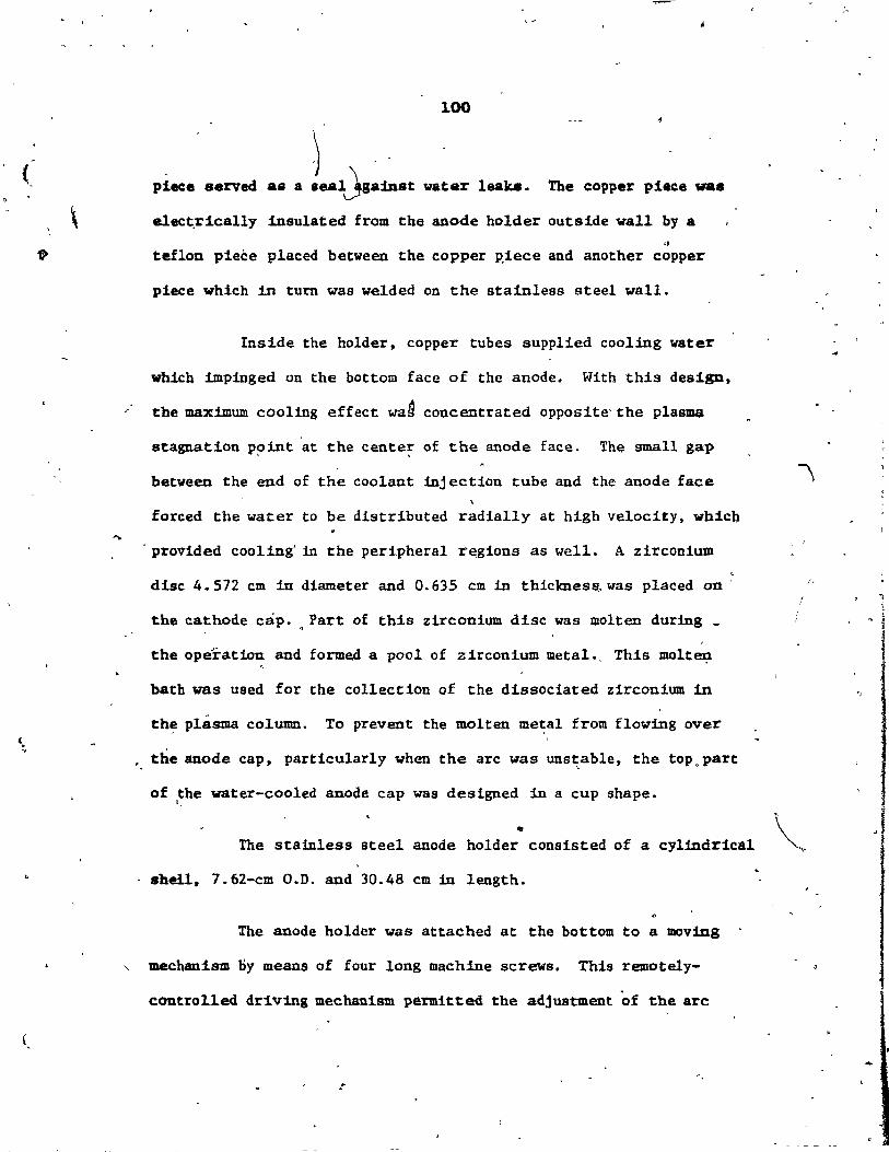
(
( . . ,
100
) ..
piace served as a aealJsainst vater 1eab. The eopper piace va.
elect.rically insulated from tbe anode bolder outside wall by a
" tef10D pieèe placed betveen the copper p.iece and another copper
piece which in turo was welded on the staiuless steel wall.
Inside the holder, copper tubes supplied cooling vater
which impinged on the bot tom face of the anode. With this design,
the maximum cooling effect wa~ concentrated opposite'the pla~
stagnation P?iut at the center of the anode face. The small gal>
betveen the end of the coolant inj ection tube and the anode face
foreed the water to be distributed radially at high velocity t wbicb
. provided cooliug' in the peripheral r~gions as vell. A zirconium
dise 4.572 cm in diameter and 0.635 cm in thickness.. vas placed on .
the cathode cap. " Part of this zirconium dise vas molten during _
the operation and formed a pool of zirconium metaI.. This molte;t
bath was used for the collection of the dissociated zirconium iu
th~· plasma col.umn. To prevent the molten me~al from flowing over
• the anode cap, particularly when the arc was unst:.able, the top. part
of the water-cooled anode cap was designed in a cup shape. "
• The stainless steel anode holder consisted of a cylfndrical
.• hell, 7.62-cm O.D. and 30.48 cm in length.
The anode holder was attached at the bottom to a moving
" mechanism Dy means of four long machine screws. This remotely-
contra lIed dri.ving mechan1sm permitted the adjustment of the arc
-.
/.
\~ .
1 1 ,
, î
1 .{

P'
101
l..eDlth Il1ld allowed the movement of the anode in a vertieal direction
lover a distance of,44 cm. A 1/2 HP n.c. mo~or was-connected through
the motor shaft to a threaded rod w"hose rotation permitted accurate '0
posit1oning of the anode assembly in its axial direction. The motor
vas operated with à precision speed controller and a forward, stop
and reverse swi.tch. The stand was supported on two tracks whicb
provided forward and backward motion. This Îacilitated the access ' "
to ,the anode. surface and, the inside" of the bot tom flange of the
1 reaetor chamber. .,
, , The exper1mental work carr:1ed 'out in the Urst stage o~
this. project (Kyriacou, 1982) was nOF tntended to' collect zircon:lum A
Metal and therefore a cald instead' of a molten anode ws used.
9. Reactar Chambèr ( .. A ~
In Figure 7: a schema tic diagram of the reactor system i8
shawn. It consisted of the reactor chamber, the cathode assembly .
and the anode assembIy. The reactor chamber consisted of a water-
cooled 28.575-cm IoD. 316 stainless steel hollow shell' 21. 6 CUl in
height, which was closed at the top by a 1.2 7-CUl thick stainle8s
steel cover, and at the bottom by a O. 9525-cm thick brass caver.
These cavers were attached with six 1.. 27-cm machine bolts each, onto
l.27-cm thick f1.anges welded at the ends of the reactor cylinder.
Asbestos-based gasket rings O.3pS-cm thick were used as seaIs, and,
also served as electrical and theJ;lD81. insulators. For additionai
"
...
, ", ,
r r l ~
1 \. 1


, .
!
','
d ;
'"
, ! ~,
Q
, , ~
~----~--~---~-'--4~ _r-,------~--------~
1.27 cm
C.W -"'c:::=t=I IN
, EXIT GAS
....... _ .... A~OE MOVING ~UPPORT SYSTEM "
..
". /
"CATHODE ASSEMBLY , . ANODE ASSEMBLY
<l-
EXIT GAS , .
". , .
> 1
.. ;,
STAINLESS STEEL 316
"" c.w. OUT ~
/' STAINLESS STEEL 316 WATER cOOUb R~R . oqUBLE WAU.
9
'ASBESTOS GASKET
fi;
1\
'Â . .
, ." , . ,
'- . '
..
, .
l ", { "
f t i . l ~ j'
j
l 1 1 i I l
f l 1 ,.
"
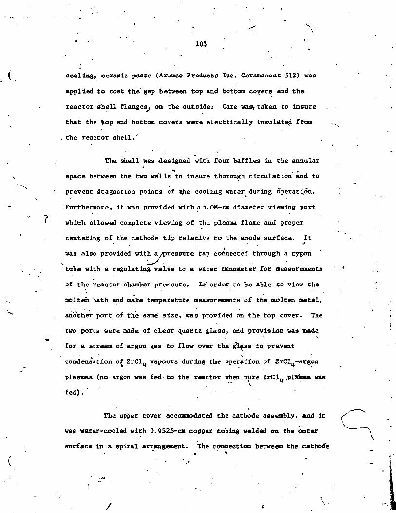
\
l
..
(
D
103
sealing, ceramic paste (Aremco Products Inc. Ceramacoat 512) was '
applied to coat the~ gap between top and bottom coyers and the
reactor~ 'shell flanges, on the outside.. Care wast taken to iusure ~ ",-
that the ~op and bot tom cavera were elect~ically inaulstep fram
, the reactor shell.·
The shell was designed with four baffles -in the annu1ar
~ ,'0
sp~ce between the two wà1ls to tnsure thorou~h circulation and ta
prevent stagnation points of t;he .cooliug water during ôperat1,6n. "
Furthermore, it was provided with a S.OS-cm diameter viewing port \
r whi"Ch allowed complete viewing of the plasma flame and proper
centering of the cathode tip relative ta the anode surface. lt o ,~ / .
W8S a1so provided wit~ressure tap connected through a tygon ~
tube with a regu1ating valve to a water manometer for measurements ,t
. .
of the reactor chamber pressure. In",order to be able ta view the .
molten bath and make temperature measurements of the molten metal,
anoth~'r port of the same size, W8S provided on the top cover. The
two ports were made of clear 'luartz glass, and provision was made
for a stream of argon gas to flow over the g~SS to prevent
condensation o{ ZrC14 vapoùrs duriDg the aper:,aCion. ,of ZrCl4 -arg~n
plasmas (no argon was fed - to the reactor whe,n pure ZrCl,~ \pllr'sma W8S \ .. ~
fed) •
The upper caver accommodated the cathode assembly, and it
wa~ water-cooled with 0.9525-cm copper tubing welded on the outer
surface in a spiral a~angement. The connection between the cathode
,,0 0,
/
,"
\,

(
.. .
-, .
104 • •
nozzl:-e and this cover was sealed with an àêbestos -gaske t to
~1mize heat transfer and prevent electr:t.càl contact betyeen the ~,
two meta1 bodies. F-or additional, sea1ing, the ceraie paste, 1 ~
lIlentioned -previously, was also appl1ed.
, \J' - - \>
- In the bot tom c~ver. t.here Were two 304 stainless steel
0.9525-cm LD. gas exit ports place (!~uidistantly- from th~ anode. l ,-
The anode entry port was large ~ough·to accommodate both the anode - -
cylinder and a nylon sleeve. Two, "0" rings on each ... side of the - ," ,- , .
> -'
sleeve se~ed as a seal arid ,the sleeve a1so provided the electrical
and heat 1nsu1atiOll-, between the anode and the reactor bottOlD c'bver.
10. Exhaust Gas Condenser
1 The schesaatic d1asram of tf;le exhauat las condeD8er ia
shown in Pigure 8: It conaisted of a waCer-c.ool-ed 316 sta1nlu.
atee1 hollow cylindrical shell 12. 7 CIl iJ;1 diaetar and 22.86 CIl. in
lcsth. with circular cover plates at ~eh end. One plate
aupported the t1fO entry ports whièh 'Vere ccmnected to the t1fo ~ .
exhawst tubë. COllinS frba the reae~or. These twO ports utea.ded
frOli a raovab1e pieee alse coutrueted of 316 stainless s~ee1
whic,!a 110 '--1c&lly .. -2. 54-ca d1allerer tube. ' Pro~1on had beeG'
Mde to act~te a ru18t_ce rire to hut this tu}e in orcler
to prevea.t condf!l1U.tioD -of tbe bal1.de sitms froa th~ reactor '
ad 'plu.uing of the eI1tr.ce ~o tlle ecmclea.aer. bperta.ltaUy~ it
VU foUnd that vith the experm.c:a1 cOllcl1.t~. uaed there .. DO
MM for h~~'., ...f' .
.. ,

:.
"
"
(
1
(~
.'
-.
1
'1
...
.'
1 ~
~.\. .
"
1 h"
lOS ..
,'"
nGOJE,8
SCdlfÀTIC Dw;aAH OF URAUST GAS ccnmiJsn ...
~,
--(l,
,
"
'-~
'ï , '
,-
,)
,
t, •
. /
, ",
Cf
.',
, î 1
i ,1
r f 1 j
, "
î
i 1
i
\

~ 1" " ~
- ~ . l
0- t # ,
-\ ~ , . . ~ , , J
;
j , "-i
• , 0
~_.o.-__ • __________ """,
~ 1 a------ _ -------...... ~
, ' .. '
(
"
AI -. .. ., ,
1 . 1 ~ <> Il ..... )
~! .. .. ,-
1 ; i " ~
- , , 0
• 1 • --.... _., • ' . • 1 -j
ft =;- i' • ! i
cra 1 . li l ti .. " JI 1
ft - i .. , , 4 1
i , J. . J
'. 1 1 l~ 1
- 1 ",
,~ , ,h
-,
.\ ; 't ; , , , ,
i ..... , "
• ~ ~ _v
ut .... " ./ ~/
.. . .

1
(
106
At che other end, a 2. 54-cm diameter 20.32 cm in léng~h
cylilldrica1 water-cooled probe extended from the center of thé end'
plate through the condenser. This served as a co1d finger and
provided an additional surface for the condensation o~ ZrCI~ /' ,
vapours. On this same plate a 0.9525-cm I.D. 304 sta101ess ~teel,
-tube served as the exit for argon gas and the chlorine gas
generated by the decomposit1on of ZrCI~ in the plasma flame.
Anoth~. line, closed with a regulating valye, was used,only
/' occssionally to c.onnect to the vacuum pump, in o.rder to clear the < • . \:\
system of air and water vapour prior to operation. Usually, the
vacuum pump was connected after the chlorine absorber •
..
11. The Chlorine Absorbe.:r: and Hood
A 12% caustic solution was· used to strip the chlorine gas
generated in the reactor. The/gases which did not condense in the
condenser were bubbled in the caustic solution and the chlorine and
remaining halides vere neutralized. The remaining gas .vas sucked
by tn vacuum pump and sent to the atmosphere via the hood exhaust
line and stack. The absorber was coUstructed of a l5-liter plastic
container with an inlet tube immersed into the solution and the
exit tube end originating justat the contàiner spout. The l5-1iter
.ize vas chosen in order to accommodate the high heat generation
that results from the caustic/chlorine teaction.
, '
r 1 ! r ,
; , .' ,
• 'i
" t
. , ,
. ,
, 1
-1
1 i

o
(
107
To-prevent any backflow of the absorbing liquid into the o
condenser, an empty Erlenmêyer flask was placed betweén the
condenser and the absorber. For add'itional protection anoth~r
Erlenmeyer flask was placed between the caustic absorber and the
vacuum pump. The ex!t of the vacuum pump'was connected to the
hood exhaust duct.
A square hood one meter on the side was positioned above
the reactor. The hood was connected through a metallic dùct to an ,.
uhaust fan and then to a stack. The exhaus~ fan was kept
continuously in operation during the experiments. ta withdraw any
fugitive gas that might' escape from the system and al,so the ozone
gas produced by the high intensity radiation emitted by the plasma --arc.
. -MEASUREMENT TECHNIQUES AND INSTRUMENTATION
1.' Keasurement of Arc Voltage
In order to determ!ne the electrical characteristics of ,
the transferred-arc plasma of pure zrC14
and compare them to_that
of-pure argon, the total arc voltage was measured as a function of
various operating parameters which were in this case arc current,
arc length and the plasmagen gas flow rate. Aecurate measurements
vere made by connecting the leads from the cathode,and the anode'to
a precision voltmeter and a s,trip chart recorder. The ~rc current
él
'.
, -
• ,
i~
1 1
1 { !
1 i
, .

,.,
•
..
-.\
108 '~?1-, ..
vas measured vith the ammeter attached ta the control console. \
read1ng accuracy of the arc current and voltag~were ±5 A and
fO.l V, respectively.
2. Calorfmetric Measurements
The fractions of the input power trans~erred to the anode,
the cathode tip and the nozzle together with the reactor shell were
determined by measuring coolant flow ~ates ~nd the water temperature
rise for each section. Three ungrounded K-type thermocouples (3.175
mm O.D.) were used for measuring water temperatures. The thermo~
couples were c?nnected to an Omega digital thepmometer type 2168-A,
through a 24-point rotary selector. The precision of the thermometer '" o
vas ±O.3 C. Three separate rotwneters vere used for determining
coolant rates. Characteristic flov rates to each of the rotameters , '
were for anode O.1~9 Lia, cathode tip 0.058 Lis and nozzle-reactor
ahell 0.0467 Lis.
3. Temperature Isotberms on tbe Molten Anode
The temperature isotherme on the,molten anode were measured
using an optical pyrometer (pyro .Micro-optical Pyrometer, The
Pyrometer Instrument Co. Inc., Northvale, N.J.) focused on different
points of the molten metai through the top cover viewing port. The
radiation emitted by the arc could affect the temperature reading of
the pyrometer and to prevent this mast of the viewing pQrt vas
p
'.
,-' . •
1
.1-t
1 j . !
1 -1 1 '-.

~.
(
"
'. 109
covered acept for a small opening. Thus, the view of the point of
focus ~}y was permitted. The temperature measured this way was , ~,-
-
checked by another measurement taken tmmediately after the arc was
extinguished and while the metal was still molten. The two
, "\ temperatures chec~ed reasonably vith each other, vith a difference
of about 6-8% when the arc was turned off, because of the enormous
cooling rates of the ingot occurring when the arc was extinguished.
The values of the temp~rature were corrected by taking into account
the emissivity of zirconium at those temperatures. These measure-
ments were made with on,y pure argonÙarc. During the operation of
, pure ZrC14 plasma, the v1ewing through the ports was Itmited due to
condensation of the halide on the glass. Also, the p~esence of fine
particles in' the atmosphere ar~und the arc made the measurement very
in~ccurate.
, .. 4. Arc Geometry ~
To compare the pure ZrCl4- lumÜlous plasma profile with -
that of pure argon, still photographs of the plasma were taken using
a 35-mm Minolta SRT-202 camera vith a lOO-mm lens. Due to the
excessive light exposure from the plasma, Kodak pan-X film with ASA
setting of 32 was used. Exposure time of 1/500 second and f-22 was
found satisfactory.
•
'.
, .. .
• ,
(
(
110
5. Ana1ytieal Tecbgiques and Equipment
''1 The zirconium ingot was weighed before and after the test
on a Mettler electronic balance type PC 4400, within 0.1 g. The
ingot after the test was eut di~etrieally for a representative
" sample 0.635 cm wide using a diamond rotating wheel in oil to avoid
oxygen contamination of the sample. Due to the low combustion
point of zirconium, cutting of the metal with a regular saw ia not
'-possible. The satnple was cl~anef -~i~h Acetone and placed in a , f'
plastic ,bottle. lt was then sent Yo the analytical laboratory'of
the Noranda Research Centre, where by spectrographic scan the
existence of metal impurities was checked. Each sample wa~ scanned
for tbe followtng metal: Fe, Cu, Ni, Cr, Mg, Si, Mo, W and Al. If
any metal was detected in Any sigoificant quantity, then atomic
absorption was empldyed for the measurement of its actual levél.
Spectrogr~phic scan was also used to detect the presence of chlorine
in the sample. The oxygen determination in the sample was done by
fast-neutron activation analysis performed by the Cint1chem Inc., ~~~ . Toledo, N. Y. laboratories.
Sampl~"s from the material remaining in the sublimer at the ~ ,
end of the experimental tests after the material was rendered alkaline
" and ignited (this will be discussed in a later section). By X-ray
diffraction; the presence of Any crystal110e compound, except zr02 ,
vas checked. This was done to determine if 80y metal oxide, which
lO~ld affect the estimated amount of zirconium fed by taking the
veight of the oxide into account"was present in the ~rC14 residue.
(.
.1
J ç

(
....
111 '"
In this section, tbe procedure involved in operattng
L the experimental system is explained. Included ar-e experimental
run preparation, feed preparation, preparation of the arc start-
up, plasma start-up and operation, shutdown, determination of
ZrC14 fed, safety measures and the calibration methods. To
facilitate the understanding of the experimental procedures, the
reader is referred to Figure 9. l'
. 1. Experimental Run Preparation
The ZrC14
feeding line vas taken apart, cleaned and 1
dried. Also the n~zzle was cleaned and the molybdenum component
was checked to determine if any melting and thus widening of the
opening had oçcurred. In case of damage, the latter was replaced • .
The inside of the reactor and the vie~g w~dow quartz glasees
vere also cleaned. The cathode tip was resharpened or, replaced vith
a n~ one. The anode cup was also checked and in case of damage
replaced, otherwise just cleaned. The nozzle and the line vere
reassembled. The line along with the no~zle feeding ports vere f'
" wrapped with resistance heating elements and then thermally .
insulated ~th ceramic fiber.
.(

•
112 . .
..
Ir
.. "
•
fiGUU 9 ..
PROCESS SCHEMATIC DIAGRAH
1
" v
"'- l o •
f , " 1
1 . 1 1
\ l 1
1 , t .t , . . •
, 1
\

l'.
® Tov'"
port.
• y
Argon ~.
1--
y
AfIOft .... ter
. . , .
To .ubllmer for purglng
"
~, , \;, ".
,
.~ Cathode@
~~;'-~-~II watwln
)
. Coollng wat., ln
Reactor
Anode
r-:-Cooling .ai.,1n
, .Im o
ta o 1
L~==-=- 10 @ 1
, ) Power euppIy
~I. if "U1M!' lt! i' ltst.hlwt.1'Tk"'IoI~~·_'-' 'ILII 'QU.ml' ,ru" Il Il' l ' ... l '1 ..... ,., .... *'. #.. HI ,.' •
"
Pla.m.co"""
ZrCI4 con .......
CoolIng ®
wat ... out
...
..
1#
" . ,
" 1
,~
.1
@, .C"_I llbeOfber
.~
-
1"'- " , ,
"
To v ....
,
"
r { . l
1 1 '
i ~
1
j
.·f
. . ,
,./'<:'"
0'
~""-
4>',t '" .... _~!_1tt. 1 ... '\r,."r~ ...... .....:.,.· .. t'4"'~

(.
1 113-
2. Feecl ,Preparation
'" The sublimer vessel vas placed in an enclosed glovebox
together 'vith a balance and 'the 20o-cm.3 quartz beaker. The glove-. '..
box W8S t4htly ,cl~sed and then tvice pressurized vith nitrogen
sas, and -evacuated to el1minate mo.isture and atJDOsphertc oxygen,
which could react vith zirconium tetrachloride. Finally', the
-glovebox vas pressurized vith nitrogen.
The zirconium tetrâchloride vas kept inside hermetically ,
c10sed plastic containers. These containers were kept at aIl times
,wide the glovebo~der a pressurized mert atmosphere. A' \ .. ' '
predetermined amount of zircon:f.um tetrachloride vas weighed
together vith the quartz beaker and then the beaker w~s p~aced
inside the sublimer onto the fire brick. The sublimer top cover
vas screwed on and tightened with three Allen screws.
3. Pre.paration of the Arc Start-up
The sublimer was brought ~?e plant and'tts outlet was
connected to the ZrC14 feeding line attach~ to the nozzle. Cer8lllic . '
paste (~emco ,Products Iuc., Ceramacoat 512) was used to coat al1
the junctious on the sublimer, in particu1ar outside of tbe top
an) to prevent , cQVer and vessel flange gap, ta ensure air tightness
the escape of toxic ZrC14 vapours. The in1et to the sublimer was
coanected to an argon cylinder and va1ve'4, on the ZrC14
feeding
.. -
-.

(
(
'" ,.
0
~
;,
114 \\ " 0
./ ~.,
/,.""
connection of the sublimer and filled with argon.
as a solid in the vessel and Hel which however does not represent 1 • l '
a contàminat!on of the product:
Th~ zirconium ingot was weighed and placed'on the anode '
cap. The cathode was properly centered withtn its nozzle; and the
~ ",anode aasembly was. raised, 1,lsing the anode moving mechantsm, such .'
that the anode surface was about 5 mm aw~y from the catbode tip.
The power 011 the heaters for th~ ZrCl4 feeding line~
argon line, argon hek~er (A) and sublimer cartr1dges was turned
on. The power setting was increased gradu41ly until the f~al , -
setting of the respective variable autotransformer was reached. , ffi
The, ~emperatures in 'the lines and the heater we~e individually
mon1tored by thermocouples and were read on an 'Omega digital \ \ 1
thermometer 2l68-A. When the temperature in the lines was in ~ :"
excess of 613 K, 'the heating of Qthe ~ublluner was sta~ted by
positioning the BUnsen bunier under the vesse!. .'
, . , :
- '.

'"
.\
1 1
1
115
Since zirconium 1s a very efficient oxygen getter,
el1.Dl1.uat:Lou of oxygen_ fram the reactor was of prime importance, ta
prevent the formation of Xr02 on the anode surface. This vas doue
by ext~sion flushing of the equipment with argon gas. Because of
equipment limitations it was impQssible to cOl1lpletely sea1 the
reactor, so care had been- taken to always sustain a positive pressure
inside the vesseI to prevent air inleauge.
The temperature of the sublimer <as shown by the theriao-
couple positioned Just above th~ po"Per ZrC14
surface), vas allowed
to rise rapidly untll the sublimation temperature of 604 K was
reached. at which 'time the temperature remained steady for same time --
(for 30-35 g of "'ZrC14 charg,;d the Ume was approx.imate1y 15 min)';
Att
this time; the coo1ing water to the various channe1s vas tumeci on
and adjusted to',the desired flov rates. theil, with an obpDeter 1t
-liaS ascertained that the anode, the cathode and the r'eactor chamber
..... if
vere electr1cally iaolated fram eve;nrthing else. Nes:t, all the
electr1caJ. dev1ces -in the_ laboratory were discOtUlected, the reCt1f:L~ \ ..
~ power vas switched on and the argon flow rate, through the uozzle,
liaS set to -14 L/fdn in arder to test the high-frequeDcy start-ùp ;
syst_ anel to check whether there vas a need t? reacljust the arc gap.1
4. Plasma Start-up anr Operat:Lon
.. ~ When the taperature in the sublimer, after beiDJ .t-eà4r
~
for SOIIe t:lme, baga 'to r:Lse r.pid.ly above the 8ubr:i.aation_ pciÛlt -,
, .
, .
.-
(J -",
.-
0'
l,
'<,
.' ,
" ,
lf', , ' , ,~ .. 0 -;
'"
"-~ .~
) 116
("'100c/ain). the arc vas 1.gnited. us1ng pure argon at the rate-of
- . 14 L/aiD •. 'x-ediatel.y JollovUlg igDition, the el.ectrode .. gap, was.
increased ,to t:he duired va1ue.
When the temperature in the sub11mer reached 673 ~ (phich
W&8 found to be adequatè to d~ive the vapours to the 'reactor), t:be .. 0_'
val'te on- the ZrC14 feed:lng line was openeèl çd ZrC14 was .fed into 'the
reactor. "The ~resence of the ZrC14 vapour in the plasma, arc was
iaed.iately perceived by the sudden increase in t.he arc voltage and, "
the subsequent: current decrease, and àlso by the change in po1our
an~ shape of the p!asU~ column. The power input bad to be increasec:!
1DIgediate1y to sustaiD the arc. The argon flow rate was gradually . , '
-1!'educed as the vapopr flov rate increilsed due ta sublimer temperature
r1t\é. When sufficient to iaustain tbe arc vapour flow rat:e was
_~abli.hed tbë a~8011 va8 eut- off frma .. bath viewing windows and . , ,
'nozzlé. 'The arc R •• tabU·~ed br fdjuatiDg the curtent:.
_ ~ 'r ~ 1 \ J
, .
Du,::1n8 the' exper~t thé àetting of. the variabl.e auto- :, , ,
" trau.fomers vas, cOllt~usl.Y' 0 .juated·1O 0 t:hat the taper.tutu 'in , • 0, ' -, , , \:'
~ ~ h ~_ ~ ,
the l~ ,would 'Dot ~al.l bel.OJf 700 & ~, iD the ,-,.-ter CA) belov . . ,
810 K.' ,
, • 0 , 0
. 'S, Sl!!tcbm' ,
. , '
" , , , '. '
\... '" ~ . ','\ ,."
, \
, . ., - J # _ .. ,,~ ,. -1" p
~ "a:aci . Qf' the' ~Wat -~: cl~~ed by tUtabUit,. '. ~ l, "' .,,'. ,:... , ,"" • ~. 0., • ." ~ .. 1<
fa the, arç, .. the .~pply .o..f %~~~ bec._ ,.,.",ted. ,~. t~ii, po~., .. • • \ .. " _. ..to < • ..... '. ~, •
"
" . ,. .... \,.0. .. "1
" q , o' , \ .... : ',' .... :.
\ "
, 1
1 .. , . "
.. .' ,
, , . -, " \
"
. \
.. '- ".\ '.'.. '
" III' ... l' .", .. , . ,,-' ..
~ .. • 01 -.4 .. ~,\
• ( , J , , ,
or
l "
0'
..
~. l "

(
. "
\ o' -
117
\ -'" the argon ws turned cm again and the power switchecl off. The .
- • cool~g vater and th~ flow of argon gas were kept on . ta cool the -
zi.rconium. ingot and maintain an inertatmosph~re.'
The anode .vas withdrawn from the ~eactor and the
z:1rconium ingot was temâved and we1,ghed to tbe nearest 0.1 g. theil
the ingot. W&S eut and sampI es px:epared for analysis.
""-
If;
6 • Determixladon of ZrClq. Fed
The subl~ér took approxilllâtely two' hours to .... cool down. • • •• lt vas disconnected from the line and the toP. flange opened. A11
~he' relllaining power in the vessel f 'ou the ~op flange ~ the
'l;uartz bea.ker vas dissolved vith dist:1l1ect vatel' and transferred . ,. ~
. tO' à pyrex bea~r. Tb~' ZrC14 feed~g line vas a1so cbeeked for.
aceUlllUlat:1on ~#lCODdenSed ZrC1 .. ; - and any amo_~t preseIlt va.
transferred ta the pyrex buter. l'he solutiÔD in the' bea~" " J ~ '. ~
- rea.dereci alkalinè by tb.e &ddi~iou of .-.ulua hydrox1.de. The
. \ auapeIJ810D wu f lltered through Wbatman No. 42 paper. The preei-
p:1tate -and paper were transferred ta an aiua1D.â cruci.ble. The
eru:cible ... placed ul ~ ..ufle furnace and the taperature ...
aaütained at 523 ~ for tvo bour. t~ dry f _4 the ip1ted to
COIUJtàn~ weight at 1,073 .~ 1,273 1.' lt wu tbeD c001ed' and we18hecl
.. ~2" Fra. a ZircoDtu. bal8lc:e the .-:nmt of ZrCl-. ted ... tbUa.
.tÛlAted.
, .. -
\ . 1
- -~t
, , .. ' 1 ,
. r J
r " ., '
. : î.
'.!. ...,,-' . - . "
'-1
(.
, \
.,
)
. ,-
7. Saietl Meaaures
-118
' ..
, . Beeauae of the t~ity of zrc14 and the h~h inteD.ity
/ 'rad1.atiou emitted by,tlle arc colual, preeaut1oa&ry,uae&sur!s ~e of
.rtance in the operat~ _of the aystem.
ZircouiU1ll tetrachlodde powder expo.ed to the atllO.phue
, reac ta vith lIOisture and releases chlorine, gas whieh 1.s highly toxie.
'Also. ~rC14 vapours are theaselves toxie and duriug sub11llat1.011 or •
beating of the 8ub11mer vesse!. accidentaI leak of SOJae vaPours , -. .
- , cou1d oecur. During au exped.lU!lltal nu1 or any ~dling of ZrCI~
.. ,
powï(Jer sas. face .. sb ~Ulsou Jl-68S) ve!;e ,warn. In AdditiOl1 to the
---.. , , ,
hood over the pUot plant. all ZrCI; vapour-c_~ta1u1ng stre.ams vere
•
.,..aed tbrough condensers pr~or to exhaustion to tbe outdde. Tbe J
-:In str ... IMv1D& tbe reaetor vas bubbled tbrougb a eauat1.e , ,
or ZrCI) ,_eratecl in the. reaètor. , "
alov" to
\
The h1&h 1nt .... ~ty racU.aciou .-1tt8Ci by the pla .. col ... ar.,.
ca eaue .artou. eye ~. 1f v1. .... vit_t eye protection. Th.
ue: eol_'~ ob.ened cU..rec:tly QlÛy tbrouah an e1ec.tr1.cai. ~cliq , . . - ~
hel8ec. AJ...o. thé Uv racl:f.atioa froa the pt..a eould aüo 'eauae , , ,
buma _ 011 t~' aida.. .ad tbua care wu ~ lIOt 1:0 .,.. .. bar. akm
1 /
, "
" ,

,',c
.. '
, "
~
"
l, (
."
.. ~ . ~~
..... ( .. <
, "
"",'
"
U9
,C.rai-c: fiber cd .sbe.toe, the uterial. uaec! for
beat1D8 :lnaulation, are made froID fibers chat poae heal.th bazarde
if Ûlbaled, '8IId furthe~re, lIicrol!c::o~ic:: ceramic fibers -caus •• ~
irr:lt~t1on. BandlilÎg of these materials was only done wearing
... ka and loug-sleeved eloth:lng.
The equ:lpaent stand vas carefully_ :1ii.ul.at~d frOli &11
'. curr.e.at;"carry1.ng parts and aU elec::tr1~ally-operated ~1ts were'
, . properly grounded.
_. Pot add1tional protection plastie gl.ovee vere
, • vara clùring the exper1aental runs .. . . \.
A8 several. parts of the syst.. vere kept at very h1.ah
taperat':ttes, constant care ~ to be uer'cised. , ..
, 8. Calibrat1.on MethOde
,The cOlllponeQts of the system that requ1red cal.ibrat:1.on
vare ~he gas rotametere for accurJte meesure of the argon 'f~oww,
_ci - the ZrC14 eubl~r to determiDe the flow rate of tetrabal.1.de
Va~ fad to the reactor •
. i. Calibration of the Arlon Iot_tera
There vere twcS -argon ~otameters in use. One .... usecl to
- -•• aure tb., flQW rate of the argon supplied to the reaetor ,tbrouah
~ - the lIO&zle,o 8Dd the other th~ argon supp1!ed ta the view1Dg viDdova. \
\ -n.-lrotaMters vere directly dovo-scream frOID the argon cyl:1J1ders
.. -~.
. \
1 ..

(
",
\ \ .
«) -
120
. . ~ vere operated at an inlet pressure of 344.5 kPa (50 patg). They
vere calibrated vith an Amer1..can Meter Company, Model 807. wet test
.. te~
-< 11. Estimation of Feed Rate
In the first stage of th1s project (Kyr1acou, 1982), =
carrier argon gas was used to convey the ZrC1lr
to the reaetor and
the estimation of the f10w rate was accomplished by using a
condenser do.wn-stream from the sublimer (the reactor was not in ~
operation). The -argon-ZrCllj. stream was directed to the condenser
·and by measuring the weight of Zrç14 condensed, the amount fed ta
the reactor, for the given argon f10w rate, was found. Then the
assumption that the sublimation rate during the test was approx~~
mately constant was made (the duration of 'these test,s was 6 min)
and t'he flow rate was calculated by dividing the weight of ZrC14
eollected in the condenser by the duration of the test.
The present work was based on the production and operation:
of pure ZrCllj. plasma. Because there was no carrier gas, the va pour
.pTessure deve10ped in the sublimer was the drivtng force for the
feeding of the' vapours t~ the reactor. The sublimer-condenser
~stem, used by Kyriacou had' to be rej ected because it did not
aceount for, the change in the flow rate due to magnetic \pressure
or Haeckel' effect .which occurs when the pla~ arc i9 on. This
effect indue es a pressure gradient near the cathode spot, thùa
1
"
"
1 \,
J

( \
121
_ sucldng the gas into the arc from arounq the cathode and causing i.t
to form a high velocity jet.
~e use of flow metera was also rej ected becà~se of
,iJevere limitations imposed by the operation of the plant such ~'s
h:1gh temperatul'es (above. -673 K) and a very corrosive environment:
The procedure described in a previous section gav:e more accurate
reaults because it was l'epresentative of each sepal'ate experimènt.
The exact amount of zrCl4
fed to t,he, reactor was determined for
each experiment and.thus the product conversion was more
aecurately calcu1ated.
In a11 formaI runs, the initial charge of ZrClq. was in
the range of 30 - 35 g. When the reactor was o.perated with pure
ZrClq. plasma, the power input, compared to that of pure argon arc,
~wa8 doubled and sometimes trip1ed depending on the ZrClq. flow' rate.
When the l'eactor chamber ~as deslgned, in the first stage of the
proj act, there were no data available in the I1terature about the
el.ectrical charactedstics of pure ZrC14 plasma and the coo1ing of . " the reactor top flange was under-designed. In order to prevent any
.
..
(, equipment failure the t.otal operatmg time wss restricted to
approximately 20 min. By, using 30' - 35 g of ZrCl4
in the sublimer
and the conditions previously descr1bed, the duratl.on of the
81I&bliJllat10n process vas 12 - 13 min and .consideting the time
~rwming -with argon the total experimedtal time Wll'S in the order of
20 min.
l
'1 --.-i
•
,
1 Il J
- 1
1 l

,1
\
122
A characteristic voltage-versus-time diagram- i8 shown in ~
Figuré 10, for a current level of 370 - 380 amperes, as, was recorded
t:t by the strip-chart recorder. This graph ta divided into five .
distinct sections. The firet one represents a pure argon pl.asma
arc. In the beginning of the second section the feeding of the
zrC1.4 vapours was initiated. At: the sarne time the argon flow rate ~
was slowly reduced and in approximately two minutes, the flow of
argon, from both nozzle and viewing windows, was completely stopped.
But due to recirculation of the ga.e. inside the rea.ct;")hamber
two 'additional minutes were required to. completely el.iminate the
argon from the arc and for the volt,age of pure ZrC14 plasma to
stabilize at the value of 42 volts. In the fourth seèt;ion, the
voltage of the p~re ZrCl4 plasma was increasing in an approx:imately
linear fashion and then 'at the beginning of the fUth section there ..
-;was a sudden increase in the vol.tage. At 'the end of the fifth
section. the vol~age deereased sharply and argon had to be turned
on to sustain the are. The only variable changing during the
experilnent was the temperature :in the 'sublimer (rang:ing from 673 K
ta 733 K) and thus the flow rate of the ZrClLj. fed to the arc. thë'
variations of the flow rate during the experiment coul.d not be 'il
est1mated directly. The average flow rate was calculated by
dl~iding the amount of zrCl4 fed by the duration of the experiment:
The asaumption was alao made that in the sections 2 - 3, 4, 5 the
flov rate vas inerea.mg iD a linear fashion.
,
Î
1 "

123
.:: 1
..
'- ' ,fiGURE 10
CBABACTERIStIC VOLTAGE-VERSUS-TM
~ UPElllMENTAL CURVE FOR PURE ZrC1q. PLASMA
, .
. JO
('

· .

..
124 > •
", ~ 1
In a number of experimenta.the arc vas very tmstable for
var1OU8 reasons (for example, the cross7"seèt1onsl area of the
1IQlybdeDuIIl nozzle w:l.dened or the feed1ng '!-.f ZrCllf vapo~r wa~ not
. a,.at!trie because of .condensation in one of -the feed1ng ,porta) and
bad to be terminated: or could not be sustained. In 1DOst of these
expe~:l:ments, the arc was switched off when the voltage-versus-time
curve wa~ either in sect ions 2 - 3 or 4. and this .could be
determined by the recorded voltage and/or ,the range of ~he sublimer ~
temperature. Utilizing e:xperiments terminated in the cOllbined
section 2 - 3 the average flow rate for this section vas estÜDated. w
The av~rage now rate of the section 4 was calculated using
experiments terminated in section 4, by estimating the total amount
of ZrC14
fed and from this amount subtracting the amount fed in
section 2 - 3. In the aame manner, the average flow rate of section
5 was estimated by subtracting the amount of ZrC14 fed in sections
2 - 3 and ~ from the total amount sublimed in the c~mplete experi-
Il~tal runs. By linear interpolation the variation of the flow rate
during the experiments was estimated. The results are presented in
Table 1. Despite the fact that J;:he _estimated values of the flow
rate are approximate, the error involved should not be great because
~ue to good reproducibility of the experimental results the average ~-~
f1~w rates calculated shou~d be' representative.
Every two montha tests were also performed to check. the
purlty of the feed and to ensure that no oxidation to zr02
had
,occurred during the time the dehafniated ZrC14 was kept in the glove'!
boX. In aIl tests, no contamination of the feed was detected •
, 1
'.
(
\.

, . ~~~"'~.J"i'., .. ";lo.~ _ ...... ~ ~W;.~""~ ~~ ~ ... -'"-"\. ........
J .
da . ... . ~
" "
\
Section. of Bzperille:ntal CU". (Pipre, 10)
,.
2-3
4 ~
5
us
" .
i.uu 1
Peed rate f?f ZrC14 s/ain
Besiu.:lns' of Section
'1.0 /
1.2
1.5
..
'.
End of Section
.1.2
1.S
2 .. 0
- .
. , '.
lt.aDge of Sub.l,.1lDer
T_perature , (~) .
67~710
710-122
722~733
'Il'
"
, ,
p
,. ~.'
, 1 • !
1
t~
, "
-'

. (..
\-, .
. '
'. 126
USULH AJIÔ DISCùSSIOH
In the previous sections of th1s theeis, the design of
.the aperiaental apparatu'. fo~ the production of a pure ZrCl4 '
traasfeùecl-are pl: .... , the procedure of, 1ts operation alODg witb
the ausuraaent tecbniqu~8 and the instrUllentation 1,lsed, have been ' .
deacribed in detaU. This constituted a major part of the work.,
becauae due to tbe l1ove1ty o-f thé st1,ldy a certain amount _ of
c~ty. bad to be d:lsplayed and, in addition, due t~o the
e~lex:lty of tbe operatian of the plant a certaiIÎ amount of ttial . , ,
and enor vas i:Dvolved bdo!:e reaching the final' sta$es of the '. ~ '. ,
l'
.tudy. ' • ,
. Tbe .y.t •• a. lt bas b~en 'descrihed. bad some equipment
~1Ja:ltati!1D8 wb:lch ÜJIpo.ed a nuaber. of . restrictions on the '(peratiqp 1 1 _ t ~ •
q.f the pl.ant and prev~t~ .. ~re ext~sive and d~tai1ed 8tudy, iD.
th~ . \1A!ted ~ule àv.Uab.l-~. SUlgestions fJ),r SOlDe equipaaent, t'
Jll?d1f1cat:lOns will be gi.ven in a later aeet:lou; "
Th~ results of the exper1Jaeotal wor.k are discus.ed in th:ls
'.ecti.on. General. obServations on the pure ZrC14
'·.rc and ·t~e . . a1ect~od.* .re·prea.f!l1t~ firat. The arc voltage depeudeneie. of the
Z~l4 ~re. ~re· theu 'shovD .S _. funet,iOR o~ varloue. ~raaeter~ to ;. - • Il • ~ •
. pr~Ue iDfôt:aation' ,aD -tqe eleet~1cal' cbarac:teX'1atie. of the arc, , '
.. \ ' . ,.-/
and 1t 1& &180 ocap.red te:? argon and 11.1t~08_ arés. The overall anode , ' r' ~,
cergy tran_te,r 1.8 thers pru8I1ted. folloVed hl' the .olten. bath tellP8l'-~ \ . ,
~~ •• P:'~l',~ the rec;overy of th. aue~"t~ ia d1acuaaed.
"
" ','
p
- .
.1 ,
.',
l J
• 1 1, ,
, ~
li
:', . t j
, .
. l i l 1
.j
. "
, ~
! ,

" ,~
" , ': .' ~.
-;,:
(
, \
'1
\'
, , "
J~'
0
127
General,Observations .~,
The geDera~, appearance aï. tbe arc col\llll[1 iri a· pure ZrCl .... ,
system lias cOmpletely' different from the argon or n~trogen arcs •
• Figure 11 shows two \photographs of the arc column produced by the
.' same ttor~h operat~g with pure ZrC14 and pureo
argoDf l'he ZrC14 t. . ' ,
o
, ~
column appears\ to be' much larger in diFlllleter compared to tlle argon
aTc unger the same operating conditions. This, however, may have. -
~ been dmply due to the presence o~ more radi~tioll emitted in the , .
... "
visible spectrum thruvin the case of tbe argon plaSUla.' .lt. was
~Uso observed th~ the diameter of tlJ.e· IJ,ilninnus arc column' 0 't,
.", , f ~
increased steadily along its length,' enlarging cons1derably near ~ , - '" 0'
the: anode and covering almost' com.pletely the 4.57' cm: a.D. ~1r~onitJ1D ~ .1'" e.
(1 /) () 1
ilÏgot.~ ~e ZrC14 plaS1D4 flame, was characteristica~ly ~in~ lo!~f!n ' .'
v1ewed through a welder' a helm~~, or l.ooking at tts reflecti~n" fro~ ~ • p ~
an object. lt 1s interesting to note thBt if even traces of zrC14
vflre added to an- argon arc the colour and shape of the ar.c changed' . " < '
sisnificantly and th~' ZrC14 presence could be '1mmed~te~y perce;Lved.
The major char~cter1stic of the pure ZrCl .... p~asma i8 the
eoo.siderably high power required to maintain a stable arc. - - c ~ 1
~. '
COIIlpared to argon plasiDa arc of a 1II8SS flow rate of 24.9 glmin (:J _.."
(14 L/min), the ZrC14 ~rc of a mass flow rate of about 2'.a/min, - -, .-
required doüble, tbe power of the argon .àrc. The required power', in , "\'
the ran,e ,of Zr~l .. vapour flow \~eJ:e8 st\Jdied, ap~eaièd to be a
8ti'orlg' functiOn pf the ZrCI~ flo,i rate, increastÎ1$ 'in a c.l0!le l1near
'" ., \ ,
, , , , '.
" ,
'.,
. .......
\
: .., .' ,

128
{ •
FIGURE 11
PHOTOGIlAPHS OF PURE ARGON AND
(
r Q
• < . ,

" , . -:. \'
"
"
-.. -
'.
'.
..'
--
--

'-
"
. ,
;;- '. , 129
, .ft. , faahioa vith flov rate. CoaPared also to nitr08e11. pla .. are
~er s~ar op;rattng cond~tion. (14.2 L/min), the ZrCl~ are,
o~ the same flow r~te p'reviously JIlentioued (2 g/min), required
\ -approxt.ately l.5-t~s the power ~equired by nit~ogen. This 1. ) ~ , - ...
j:l '- b~viour can 6~ attributed -io the penta-at'amie ~leeullf of ZrC14
,
. ... -;-
"", .
coapared !to diatomlc nitroge:n and monoatomic argon molecules, and
to the much ~igher heat cap~city.of ZrC14
• , .
On~ of .the', major problems ~countered in this study,was
the unatable operatiOn of the arc, as indica~ed by -the current and , .. '
~ol.tage flucb+&tions, observed in a large number o~ ex~eriment8.
This unatable oper~ioD was not 88sociated wit~he~ZrCI4 plasma, - " - .
~ _aS proven by' a number ~of erper1ments with relatlvely stable opera-~ .,.. - ~ . -
, tlou reseaabl1hg the ~.erat1on of argon -or D;it~ogen arcs, but was .. . ',rather attripu~ed to prQb+eIIUI assoc~ted rlth the sublimati:~'
, 1
proceas, . and equipiaeo..t design limitations ~sed by thè natu~è of .',
~~14 vapeurs. Because ~he averàge flow rate""Of 1.5 g/m:f.n of
ZrC14
vapeur used was very low, cOlI.pared ,ta. 24.9 g/min for stable
~operat~ with argon, the pla~ arc ~s extr~ely sensitive-to
..all fluctuations in the"! flcnr r.t~. The feeding- df the-ZrCl4 .
vapour to the-reactor was-ca.plet~y_ dependent on the Yapour pressure
deve10ped in the 8ubU.aer and the vapouratreaa exiting the vessei ,'\ . - .. - ,
... ~~ cOmple~elY cont:f.n.uoua stream: bu~ .~et:bae •••• Ulll.t!d a, _
rather s11lhtly pulae-l:1ke character. capable of causing small arc
fluctuati.ons. The .ost iaportant cause of' the fluctuatl00.s,
, ,
"'.
'- .
(
"

"
. \
" ~
1 -
-130 . / .
howev.er, vas th: "U6z~1e design. The ZrC11f, vapour entered 1:he
nozz1e 1:hrough 1:TIIO opposite ports. The distattce fram these 1n1et
port. to the cathode tip vas approximately 4.5. cm~ and des~ed iD
such a ny as ta mloimize the residence time of the vapour in the
'water-cooled nozzle, iD arder to avoid condën •• tion. Complete . .
~~1ng of the twO stream. was .therefore impossible in ~he short
_ time available. If the two ZrC11f, stre~ vere not completely
balaneeèl (due t-o either small con4ensation of the vapeur in one of
the ports-or some~here else iD the line before entering the nozzle) ~ . .
the arc would be·deflected by the stream with the higher flow rate, ,
eauslog the current and voltage to Jluctuate. In extreme cases,o
the surge in current was sueh' that insuf~!eient powe~ was available -
-ta sustain the arc, and the latter extloguished 1tself. To over-
~om.e co~densation 10 the lines, the -heating of. the l~es and 0V •
'fe~ding p~rts was inereased, as a result, the stability of the arc ,-'" ,~
~prove~considerably, but the problem was not completely eliminated
beçause it wàs inherent to the design of the equipment. An ._~
important improvement to minimize this problem will be described , '
later.
-The surfacé -of th'e molten bath was in CODtinuOUS motion, .
iD response ta the continuous JDOv~~ of the arc root. This . - \,
pbenOllenon~ w&s more prdnounc~d with the ZrCl4-plasma arc than vith
_ argon, poss1bly due to h1gher current densities used in the ZrCl4
pla_. A a1allar pbeD.qlleQOIl vas observed by Choi and Gauvin (1:982)
;.
".
, .
.... \
.
- ,
: -
, '
i
1 ,1'"
1
. ~ ~ "
,1
" 1
, .
. , -131 .
'.-"
. , 111 their study-of the character1.at1ce of an argon arE tr_ef~ed
to a mo1ten copper,anod~. ) , The deteriorat.1ou of the cathode .tip. in the presence
" of. pure, ZrCl
4 plasU, vaa initially rapid wtil the abarp conical ' , -
.Eip va" transformed to a shape rsiniscent of a beaisphere,
f~llowing which the ra~e of deter.1oration decreased, but still
-remained IlUch more rapid than in the ease of argon arc.- The
t'eaaous for tq.is rapid det~~ration are: the fairly high curr~ts~,
used (abave 330 A) and the low ZrC14
vapour flow rate.; Becaua~ of
the 1atte~, the convective cool~g of the cathode tip WBS low.
Méhme~oglu (1980) mefsured the temperature-change of the cathode
tip with the 1nlet velocity of the $a~ and showed that the
convec~ cooling plays a very aignificant role in the pr~servat;ion . of the cathode tip.
~ ~
The molybdenum piece uaed to protect the nozzle op~ing
. fr~1Il exposure to the intense arc radiation was pr~ven to be quite 1
/ 'resiatant -to rather severe conditions existing in tbe reactor .~
, ,
d~r~g the opera~ion of ZrC14 p~~~ arc. The open1ng of the,
molybden'Um piece, which ns very important for constricting and
tberef,ore stabil1Zing tbe arc, was senerally unaffected, except
when tbe arc was very un.table in' whicb case .rc~g vith the cathode
tip oecurred cauaing' meltin~ and widening of, the opening-; 1n thia , , , caee f the mo1ybdeDUIR piece had to be rep1aced. During atable
operatiœ" the lif e of the aolybdeaua -piace could- be cOlu.Uered ..
- virtually tnfinite.
'"
~. .'
" ..
.. ,
"
. - , ;
t
: ,~

" ,
(
.'
\ ..
. '
/
. '.
, "
132
" h
A a1rcORiua ~tal di.e 4.57 ca O.D. (1.8 iD), 0.635-ca __ ,.
th1ckD ... ., and we1jh1Dg apprQx1aa~ely 70 a va. uaed to fora. the
aDOd1e .olten bath. J'taure 12 .taova a photoaraph of the frozen
aDOCl. aurfac'e fac1D& tbe-pu-. aft;er a tut. It can be se. tbat
tbe iDaot cxh1bit; a .. rked c~ater-l1ke depre.s1OQ at-1ts center. 1
Al.o. its circu1ar shape bas 'be. altered, and irregular1y
deforaed f 1Dc:licaJ;1na that duriDa the operation of' the arc 11081: of
the ·.urface of tbe 1Dg~t vas in a -olteQ stàte (thia will be dea1t,
vith .ore extensive1y in a 1ater ,.èctiotl). Tbe bottom part of tbe
lngot. whieh ~s in contac:t vith the water-coo1ed copper cup. . -
app~red a1so to be defobaed. axeept the part of tht ~got (abouç
2 ca in d1ameter) which wa. di~ect1y in contact with the coldest
part of the copp~r cup wbere the _ter jet 1lI1pinged. The latter
appeared to be a~fect.a by the 'heat .s weIl but still reta1ned a
.-cotb surface.
Total Arc Voltage
/ 8y using the exper1meot~ procedure described previous1y,
t~, effects ,of the arc -current (1) t the~!c length (1) and the • ' Q
ZrC14 yapour flov rate on the arc ~oltaae were studied. The
part1cu1ar range of the parameters 1nvestigated was dictated by ~
th. Deed to a~erate a _table arc and by the limitations 1lI1posed .,.. -P ..
. by the ZrC'l4 flow rates u'!ec!. AlI the me&surements are tabu1ated'
in Appendix II. ' The total arc voltaae 1s plotted as a function of , .
1
. ,
" , 1
1 ,
"f
1 1
r' , .~: -

.. ( "
,...
.' '.r
/
/
"
. ' "
-1.;i;
.,,' 13.3
/
. 'lauRE 12
PBOTOGRAPH OF THE FROZEN' ANODE
SuaFACE FACiNG THE PLASMA
"
?
1 1
•
"
•
'. "
"
1
1

_. . '
"
' .. ,
,18lJ -\
l'
" -,.
/ '-
'"
~.
"
... ~
i> ~.;,
, ,-
' ,
.. (
i. , 0
..
, ,
r .. , ...... -,
~...6
..
" '
~,.
..
. ;(
"'1';
'1'
"
i """
l 1 1
l f f
'f
, '1 i j
"

i
:.(""-- .
, ,
134
arc current for 3 and 4-cm arc. length of pUJ:e ZrCl4
plasma, and
2, 3, and 5-cm arc length of argon plasma arc for direct comparison. ,
in Figure 13. A1so, the effects of the ZrCl4
vapour flow rate on
the total arc voltage are presented in Figure 14.
The 2-cm arc length for the ZrCl4
plasma arc was nO,t
studied because at shorter arc lengths the plasma jet velocity
close ta the anode, as measured by Chai (1981), in~reases
drastically, particularly in the high current range used in the
present experiments. This high jet cYelocity was causing the
molten metal to splash aIl over the reactor interior. Occasionall~,
depending upon the arc fluctuations, droplets of zirconium metal
wou1d impinge and stick to the surface of the nozzle exposed ta
the arc. On the other hand, arc lengths above 4 cm were not
investigated because of increasing arc instability, which could not
be corrected with a higher power and resulted in inadequate cool1ng
of the top flange of the reactor.
From Figure 13, ft can be ~een that the arc vo~t:age
increase",i!J significantly with an increase in arc length. This was
\ eK~ected ~ince the gas resistance 1s directly proportional to the
arc length. 'Compared to the argon arc presented in the same figure,
,this effect was more significant in the case of the ZrCl"" plasma
.arc.
From Figure 13, tt can alao be sem that the sU8tained
voltage vas relatively independent of the applied current. SiIIûlar
1, l
"
, , t
.J , , '!
!

"
~ • l, IL
"
• t- e } • <
• f
" l:
.'
\'
\ ..... .,
, .. nGUJlE 13 . . "
'.' " ...
st1STIdDD ARC VOLTAGE VAlllATI~ OF ZrCl~ . ' , ,
"
~. .... '.'
\ ,3,
..-'"
"
" ,,~
"\ , ,
"
" ,
-' \ • 1
, , \
"


',.
"
(
•
.'
\
\ \
.. , ,
'"
.'
\ \
, "
, ,
136 \ \
nGÛU 14
"
~ 4IC mTAGE .lMt'TIOR
WlTB zrC~ .. ·lLOW' un; . .. J
, ,
""
\ .. . ,
, ..
,'" ,.
Il ,
.. •

..
{
..
\
~ -- - -' -t'-. '
, . . .
'r
, 100 ...-----....:.------....
80
80
> a 70
1&1 C!J
,.~ 80 ... g,,- ~O . ,
'U . ~ 40
30
20
10
\
, .
, Da -1:018 cm
' .. Arc Iength ~ 3 cm
, , Arc curr.m a 370-380 , ...... .
.. , .
, if'
• <
'~
,
1~O 1.2 ,,1.4 1 .• 1.8 " 2.0 r'J'
ZrCI4· FLOVI RATE, 'g/~n "
-.
"
,
r ..

\
."
'. . ~. ",
137
"
bebaviour vas observed by'Choi and Gauvin (1982) and Mehmetoglu 9
(1980) for argon arcs." and by Tsantrizos and G~uvin (1982) for , ~
nitrogen arcs. This cau ~e explained by. the fact that the
electrical conduct~v1tieQ of these gases do not change too
r.~idly with temperature once th~ latter has-reached a hi~h
leva! (M~hmetoglu, 1980; Choi, 1~8l). lt ia believed that the
pla~ generated betweèh 250 tO,450 A had average temperatures
in this range. "
, In Figure 14 it 1s shown that ZrC14 vapour flow rate
bas'â very signiflcan~ effect on the arc voltage for tne ZrC14 ~
pla~ arc. For an approxtmate ZrC14 vapour flow rate of
1 g/min the corresponding ~oltage was 40 V and by incteasing the •. '
~rC14 flow rate by 1 g/min the ,arc voltage reached 60 V. lt i9
interesting to note ~bat the increase in arc voltage was
:approxtmate1l. propqrti~al to the magnitude of the ZrC14 vapour
flow rate 1ncrease. At this point, 'it must be recalled that the
v.~ues of the flow rate given in Figu~e 14 are approxima~e only,
düe to the assumptions involved in their estimafion. In arder to
explain this voltage 1ncrease with the ZrC14 flow rate increase,
onè of ,the fundamental principles of plasma physics should be
invoked. The Saba Equation gives the fraction of the particles
...
"
. .... ~ .
" .. '
\. ...
\
' .
, ' ..

• - \'--
\' L'" "
1>'.
1 . '."
. ,
,"
" . . (If' '. .
, " U , 1· .,
. '. 1 .. ~ \
, .
~~
138
which "exist in the 1.onized. st.ate in thermal equU1.br1um, aa )
follows:
,.
n ni/n = (21t .JkT)3 / 2 /h3 • [2U~(T) /U(T)] • exp(-eVi/kT) e 0 a
~
ne' ,n' 1. ' na c: electrou. ion and .atom cienait1.e, respectively
k,= Boltz1l!&DD~s constant
h = Plarlk' B constant
U(T) = partit1.on functi,on
U:'(TY=first cier~vative of U(T)
. "
. Vi = ionizati~ potentié!l " . /-(
"lAI '-... , e =" èlectr~lI:lic .charge ,
".&
,
o
,Thils equation c,an .be uged - to es;tilllate the degrèe of
ion:lzatlon w·'any hot . . '" ~as, . wheth~r . Qr not carrying a discharge, -
can be safèly a~sUgled. As it h~$ been r.. ' .
for' whic·h ,equilib,J:'i~ • Il
'0 0, 0 ;
stated !n"the I;iterature Review section of this thesi~, thermal ... ~ ~ ::
, ~quil~briùm ~àn generally ~e assUDled in <thermal p1i~~5 (except
_. ~. ty~_C4<~ty of electrode' ~r other",ol:1d surfaces). ther.fore
th1S equatid can be saf,ely used in the present s1.tuation • . \
'q ~l~iti~lly" the ZrC14 va pour ~19w ~a~e was small and the p~rcentage '~ .
of 'àtoms. and ions in the plasma colmun was determined bY the • ,1 \ \ li
1 ~ ~ .p , \ ' ' '\
èquil'ibrium at the given "temperature. as -can be calculated by Saha' \ f tl': t .' ~ _ • ' .~ .~
'Equ.a,tion: As "the, zrè14 f~ow rate -incr~sed, resulting in ~ t ..... Ci .. ~ ~ ~ J8 • •
increa&è .. concett,t:ratâon, of 'atoms in the are, part ot these ''atoms , . r • -.II,
" -,-' . , . . ,
, . -, ' .
1. ~.
, '. ~ Il ' ~ l .... 1 l"
- ..
. " ,
, , .\ , \ ' \ '
'Ù' *. . , . , . , , ", , , , _ 0
v ',-'''' ;
1 , .
\,
..... ... ~ .t - a 0 ~ t _-... ":....t..' _________ "_. ~_' • ........:.."'".l_~ -~-
\
---' .' ....:.~~ ....... -
\
..,

. ,
>, '
, l
139
..
bad to be ioui..zed as dictateci by the equUibrium at the given l ~ -~
taperature. ln order to .provide this additional ionaati.on,
add~t1.ona1. power had ta be expen~"ed. which depended on the
1onization potential of tne gas. This- phenolllenon would continue .---- ,,(Jf ,
ta occur as the Zrc~4 flow rate was increased up ta the point that
the core of the plasma arc would be saturateci and no more gas \
could enter directIy. but ra~her would noV in the per1phery of
tbe arc. The' uximum flow rate used in this work vas approximlltely
2 s/min whtch vas far belov the 24.9 g/min of argon usua~ly_ used
for stable operation. Consèquently. lt sbould be "eXpected that
tbe,~ requirements for the ZrC14
plasma should increase ...
suba,tantially with furthe.r increase '"in the flow ;-ate, unfortunately,
ta what mapltude of the flov rate the .. power 18 8tabUiz~ ~ ,
'this Power level 18, is impossible ta predict. ln the pres\nt
t~ta1 arc voltage in the (ange of 75 volts at 350 A bas hJ
wbat
-
work,
) recorded. but unfortunately. the correspoading flow rate' could aot
be estim8ted. The effects of argon and nitrogen flov rates on the:
total -arc voltage have be~ studied (Choi, 1981; Tsantrizos, 1981)
but at much ·higher flow rates and the pbenomena taking p1ace were
completely dlfferent.
1
l' )1
OVera11 Anode Energy TransI er' .} <>, '
Figure 15 s~ows a ~lot of the total power transferred to -,
the anode , PA' versus arc current, fbr ZrC14 and argon plasma, arc;,s.
r , 1
r ......
1
S
1 .'
}

140
-- --J,\ / ,- Qo • .J ~,
/
........
fiGURE ~5 •
'. '
POWER TIWfSFÉ1Ut!D Ta ANODE AS A FONCTION OF " ,
.. ARC CtTU!NT J FOR ZrC14 AND ARGON .. ,PLASMAS
E
."
~ / ,-
~//
/. J -/~/
': ' /'
1 II , .. /
f ~ i '
--- , ~
~,
1
? ,{ ,
e. s:
"'" .' , ,
~
\. t . '1
) -. ~
- , \
.. ,1: ~
... " , ,1 ! . . '" ,.' . - -Oz' • ~
"

/,
18~--------------~------~
• 18 'ILl o o fi 14 Z -C
e Cl ILl a: II: ILl II.
,0 Z '-C a: ~
a: ILl ~
12
10
8
e
,4,
2
Dta 1-" 11 CID
Argon .... fIow rat. 2"."",
ZrCM ..... ftow rat. ,1 .... 1 •• 8/ ....
\
7 pure ZrCI.
0'0 1.- 3cm
00 1 :1 4 cm" / o~ o ~ __ ~ __ ~ __ ~ ______ ~ __ _
(
200 300 400 500
ARC CURRENT, amp-eres
/ , .. ..
t. " ..
. \ .... )
. ,.
;'
!
" ,1 l,
1
, .

'.
..
~41
J
The affect of the arc cutteot vas -uch .ore iaportant than that ":
4lf ehe arc 1ensth. A s1aUar be~iour va. also obnrved for t?e ~
argOQ arc preaented in the '-'·plot, and for the nitrogell arcs
\
ftud:1ed by Ttlt\I.Iltrizos and. Gauvin (1982)., In teraS o~itude,
the total pOwer transf err~ to the anode in the case of ZrCl ... ~
pa.- and tbe specffic flov rate (1.8 ... 1.9 il_in), vas alJlost
double that tran.ferr~ by the aracla arc:. J
Figure 16 shows the fractions of the total arc power
tran.ferr~ to the anode (llz\.) ui the cases of ZrC1 ... and argon a!='cs.
The ef,~ect of curr~t on llA vas relatively sma11 for bot!} ZrC14
/ and argon arcs: lt bas been observed trult, in general, for argon
arcs, the va1u~ of .!lz\ decreases vith arc length and that the'
current effecOt .. on ~ is small (Choi and Gauvin, 1982). In the
case of ZrC14
, cons,idering that arc curr~t had no significant /
effect on %' % de~reased with arc 'length. This can be explailled,
for both zrCl ... and argon arcs, by the faet that arc tadiation,
caused by the arc resistanee, inereases with arc length. The
scatter of the argon data presented in Figure 16, do not allow
reaching any conclus ions.
1 1
...
"
lt i8 interesting ta note that ..!l.A, for the zrCl4
arc -was
v\ery/ close to that observed for argon, in the range of 38 ta 48%,
for a ZrC14
flow rate of 1.8 - 1. 9 g/min. On the other hand,
nitrogen displays comp1etely different values of llA for similar
..
/
, ,
"
"", /
-

142
....
-,
t;' f
......
J
, \
, . 1
'. ~ .. , "
,FIGURE 16 " 1
1
1 . / '
1
--.. . ~10N OF TOTAL POWER TRANSFÈ!iREP Ta ANODE,
,AS A ~~IdN OF ARC CURRENT t FOR ZrC1.4 AND ARGON PLASMAS
1 Il' - 1
1 " .. ~\
~ . ! / !
l. ,
J - \l
l.' _ ! " :; 1 "
1 . \
-" -1
1· 1 \
,/ / '·r
--.... / ... /
. -~ . i\ -,

, .,
-'.
•
.,. • 9
W --Cl: O
~i OC' A. __
0 &1. .... ' ,0 •• , a
~',Z W Oa: -a: "'w CJI.L -CU) G: Z LL.<
'. •
;' a: 1 .... ~
1
.-
(
. . ,
, . ,
., '
10
DNZ • 1.01. cm" 80
Argon me •• flow ,.t • • 2 •• 8·g/mJn
70 ZJ:C14 ma •• flow 'M_ :II 1.8-1.8 gtmln
60 ..
'0 •
50
QeÇl f>ru-t1 40 va ua 0
30 Pure argon
0 J. 3 cm 0 1 = 4 cm
20 Pur. ZrC'4 ,(D
1t . .1. 3 cm / '" : 10 c
0 1 = 4 cm
0 200 300 40d '. 500
ARC CURRENT, ampere~
J
1
, -
-'
1
.'
. " .. '- ...
---
(
'1 • " .. ,J ,; f
1 , \ . !
, i , i
l '
l 1
, --\ l

(
Î
143
v operat1Da condition. (c:~rr~t, flov rate and are lmath), vh1.c11 are
c.ooaUerably hiaher than 50%, and the arc: leogth ha •• e1&nif1cant
affect on the ~ value (Taantri:!0s, 1981).
- The effect of ZrC14 va pour flow rate on.n,.. is .hÔvD in
rilùre 17. AD increase in ZrC14 'vapour flov rate has a sign:l.fic8I1t
effect on ~, the latter decreasing fram 48.7% at the approximate
flov rate of 1. 2 g/min to 41. 2% at 1. 9 g/ain. The reason for this
18 .imi1ar ta tl1e exp1anation g1ven in the previous section. ta tbe
effect tbat since the resistance, which i8 "responsible for the arc
radiation. increases with the ZrC14 flow rate, tberef6re the fraction
of energy transferred ta the anode must consequently decrease. ThfL-1 ,"
effects of argon and nitrogen flow rates on ~ have also been
stud1ed (Choi. 1981; Tsantrlzos and Gauvin. 1982), but st much
bigher flow rates. and s~c_e the phenomena occurring under the
latter condi.tions are completely different. no compar:,J.son can be
made.
Approximately 4.2% of ~he total power was transferred to
the cathode cooling water (arc length = 3 cm, arc current = 380 A,
ZrC14 flow rate = 1.8 - L 9 g/min) and -corresponds to O. 94? kW. In
\ ..... the case of argon, ..!4< wa~ in the range of 5.4 to 5.6%.
a sli.gÏie increase w~th ZrC14 fIow rate.
.!4< showed
.. .)
...
-
1 ,
i l ~ .
,
\ , " -

1 1 ','
~ ~,' { .. .....,'!I.... '.J th' ~,. •
l44 "
. "
, .
"
•
~'- •
\
• 1
P'1GUaE 17
FRACTION OF TOTAL POWER TRANSFERRED TO
- .' • ANODE , AS A FUNCT10N OF ZrC14
FLOW RATE
\ '
(---

., ..

.-
(
-, .-"
. '
\ .
\
145
Malteo Bath T .. peracure
,-One of thé important problema aS80eiated vith heat and
.... ~ran8fer from the plasma a~c ~o a molten anode is to determine
the teaperature uisting on the surface of the IDOlten anode. Tbe
1.apo~tance of this temperature 1s associated vith the metal vapour ,
pressure and resulting evaporation from the anode surface.. NeecUe8s "
to say t' bo11111g o'f the anode b~th JDU8t· at al! cost be prevented.
while a temperatu.re lover than the melting point "lIlight lead to
lIlinimual or pos8ibl, zero col~ection of the metal.
In Figure 18, the telfP~rature isotherms on the molten \ ~
zirconium aurfâce for argon arc, are shawn. The measurement .f;, '
technique along vith· t.he explanat ion vhy the temperature of the
molc;en bath vas not mea~ured ,under ~he ZrÇl4 arc have, been /j
presented in tbe Measurement Techniques and Instrumentation section •. •
lt bas to be pointed out that the temperature isotberms shown in
Il Figure 18 are specifie to the partieula! operating conditions
used. The purpose of these measurements was to supply a rough idea
of the temperature of the molten bath. The two isotherms divided
o the ingot into three temperature ranges. Inside the 2320 C isotherm
was the anode spot where the electron reeombination was taking place
and this point undoubtedly was at the maximum temperature, but,
cou]d not be measur~d because lt occurs in a vëry smal1 area. This
inside area of the 2320°C ,isotherm was over 470°C superheated _ -, .
o (melting point of zirconium 1852 C) and the area between the two
..
~ ,\. '
, .

, ,
•
o
\ \
\ ' •
•
\ "! 'b --- JI'
;,
-,( '1 '-
146
\
lIGURE 18
1EMPERATURE ISOTHERMS ON A
MlLTEN ZIRCONIUM SUR.FACE~
'\
\ ..
:
\ '--
-..--
•
•
\
1
. ,
\
\
\ \ .
\
,-

J, '
,/' ,1
~ ~~
-----
",
~
'1
,
. ..
~
Il ' .
/"
'J'
,
• l'i'e .1 nvJl;olÜC"",,-~w.'" ,"",.1, $, "', ,
\"
-----
! .
~<.
p;;== . '
/ . TEMPERA TURE ISOTHERM .. l
~ ON A MOLTEN ZIRCONIUM SURFACE. ~'
'~
Current - abo A
Volt.~. 29 V . -----
10 mm Pur. _Ion pll"".,.c zirconium anodtt ,
, ~--
/"
'" ,~
. " .,......... ~ _ ..... ''11
1
,.""''''''
. '
/'
.'

147
The high.at tempeL. 0.
i.sotherms was over 330 C superheated.
0. ° measured (2320 C) was 1260 C lower than the zirconium boi1ing point.
The teJl1perature of these isotherms wOuld defin:1.tely increase under
the ZrCl4 arc, but, there' is a good possibi.1ity that under normal
operating cbditions it would never reach or exceed the boiling "" . '.".
point temperature of zirconi~ (3580°C). Eroklin et al. (1976) .,.
studiec1 the temperature distribution over the surface of the melt
in the p1asmarc melting of vanadium and stainless steel scrap ,
materials by recording the image of the surface on cine-film and
analyzing the photometrie density distribut ion. The highest
t\emperature he was able ta measure under' a 15% N2
and 8~% air arc
was only 42SoC higher than the highest one Pleasured in an argon· \
... Q a ..... arc (2000 C) .ullder the same operating conditions. This reference
18 mentloned to provide an indication of the magnitude of the \
tempe.rature change that can occur by changing the p1asmagen gas ~ ~
from argon ta a much higher pow~r-demanding air-nitrogen mixture". \ \. .
Some loCill vapourization was expected ta have takeIl: place
at ~the anode spot, b'ut unfortunately, measurement of either)
temperature or rate of vapo,urlzation at the anode spot 1s a v~ry
di.~ficult task.
The ~e cOà;l.ing water rate used in the temperature
measurement experiments was used throughout the experiments since
lt was fOWl,d to be adequate. \
\
1)
/ . \
'0
'" • 1.
• ,
\

r
/ (' 1
. 148
Production of Zircçmium Metal
At the completion of each exper1.mental test, the
zirconium ingot was weighed and a sample prepared for analysis.
-
Tungsten and chlorine, which were feared ta present a contamination 1
problem, were not detected in any of the samples, along with Fe, Cu"
Ni, Cr p Mg, Si, Mo and Al. The only contaminant was oxygen in the
"J
fom of the extreme1y stable oxide zr02
• -The presence of oxygen in
the 1ogot indicated the presence of air in the reactor chamber -,
during the exp~riment or immediately after the arc was extinguished.
Due to the extreme care taken to avoid contamination of the product
after each test, as previously explained, it was cQncluded that the
air leak was occurring during the actua! rune It was observed that,
due to overheating of the reactor top flange, part of the seal
between the flange and the reactor side wall 'sometimes broke.
Measures were taken to prevent this from happening, but the problem .. was only reduced, and not eliminated.· Ways to improve the design
of the reactor top flange wil.l be presented in the naXt sectiÇ>n.
The conversion of the zirconium fed in the fOrIn of Z~CI4
into the zirconium ingot produced. was in the range of '5% to a
maximum of 16~ 7%. Because the feed rate of ZrCI .. ths approximately
equal :in a11 experimental tests, the conversion to the product was
dictated by, the stability of the arc, wit~' the highest conyersion
attained at very stable art operation. In addition, the presence , P
--""

/
149
of ~rgon in the arc had a negative effect on the conversion,
possibly because the argon arc di1uted the ZtC14
vapour :in the
\ plasma arc, and possibly beaause part of the dissociated zirconium
may bave bêen swept away from the arc by the' argon gas.
CONCLUSIONS AND RECOMMENnATIONS
This thesis deals with a novel application of plasma
techn01o~y. Most o~ the major pieces of· equipment used :in this
complex experimental pilot' plant were nove1, both in conception
Jo
and in design aspects. Furthermore, the very characteristic f If:
properties of the ZrC14
vapour such as its corrosive and reactive o ,
nature. and the tenden~y of the va pour to condense iDto a very ....,
harpUd at the smallest temperature drop below the sublimation
1. point, (so that the temperature of the whole plant had to be
maintaiiied over 604 K) created numêrous sealing, insulating and
other operation~l problell1S. In addition, the extreme conditions 1
gènerated in the reactor in the case of a ZrC14
"plasma, made the
cooling of the cathode and anode assemblies a difficult task.
Modifications of the original plant had to be carried out, both :in
the overaU plant layout and in individual- equipment. Seme other
improvements had to be put off to me et the tight time schedule. In
spite of these difficulties it, 1s fe1t that the objectives of the
proj ec t vere ach1eved.
'As a resul'~f .the experience acquired in the course of
this work, lt is DOW possible to concentrate future experimental '
~-----_.
/
1 \

....
,
150
efforts on the optimization of the collection of zirconium into
the molten anode. ) ,
In summary. the spec.if ie modif ications that have to be
accompl1shed in order to continue the work are:
(i) The sublimer vessel must be operated at a
considerably higher pressure to Jcrease substantially the ZrG14
vapour flow rate. In order to seal the sublimer against these . ,
high pressures, the design of the vessel bas' to be modiUed because
no "0" ring or sealant available cau withstand temperatures in o
o excess of 800 C. Also, the choice of the typ~ of sealing medium '
is dictated by the fact that it has to ~e simple. since the vessel
has co be open~ and cleaned after each experimental test.
(ii) By improving the sublimer design the feed rate of ~
ZrCl4
vapeur cau be increased, so that a tangential fèeding
technique to the cathode can be B;dopted. The nozzle will have to
be modified to incorporate the tangential posit ion of the feeding
ports. This modification will greatly improve the stab~Y of the
ZrCl:-", arc and will have a positive effect on the collection of the
met:al ,PToduc t •
(iii) Better cool:lng of the reactor top flange is
\. required. This problem will become more pressing if the ZrCl",
vapour flow rate 1s increased. Better cooUng of tht{ top Hange
will permit the use of nO!' rings ta seal the reactor vessei in , replacement of the asbestos gasket presently used. which bas proven
o
fi
1 4

lfII' -
::0
- ........ ,
151
.' inadequate. Alsc, a bel10w arrangement on the anode, will permit
movement of the anode, (needed for the adjustment of the arc
length) while completely sealing the reactor.
It can now be concluded that the technique, as originally
conceived, can indee'd produce zirconium meta1 by collectins it in
a mol~en zirconium anode from a ZrCl~ transferred plasma arc. lt
is felt that the technical feasib111ty of the produé'tion of the
metal bas been estab1ished, but the optimization of the PJ'ocess
for, industrial application remains ~o be accomp1ished • . '-
A review of the more important observations and conclusions
which were derived from the experimenta1 part of this work, is as
follows:
(i) The power requi~ed to rnaintain a "stabl,e ZrCl~
transferud arc, wi.t:h"3-cm arc length and a curr~t of 380 amperes,
var1ed from 15.8 to 22.8 kW according to the ZrC1~ flow rate, which ,...
~~ varied between 1.0 and 2.0 s/min. When these results are o
'\ catnpared to the ones obtained for an argon plasma using the same ,
torch and under simUararc lengtl;1 and current conditions, it was u 1;.
. observed that t.tre Zrl:1q. plasma are .required as tlN.(:h as tvice the
power needed by argon arcs, in the range of Zrc14 flow rate used in )
this study. , ,
(ii) The ZrCl4
' f10w rate has a very s:1gnificant effect(on
the plasma arc pow4tr requirements. lt vas found chat the total powftr
increased alm08t linearly vith inereas1ng "feec:l raté-, ·for the range of
ZrClq. feed rate stud~ed.

o '
, "
, (,
152,
(iH) It was found that although the arc voltage ".
pepended strongly on 'the arc length and on ~he ZrC14 flov rate,
"~\> it depended much Iess on the curtènt.
(h) The anode energ~ transfer depénded strongly on arc
current. Hovever, the fraction of the total energy transferred to . '
"1
the anodè depended more on the arc 1ength than on the arc current. ,1
The fraction of the energy tran'sferred to the anode was also a
strong. function of the ZrC14
flow rate, decreasing approximately
linearly with the latter. The fraction of the energy transferred ~
to the cathode tip was invariably small and aImost independent' of
arc variables (arc-' current, length and gas flow' rate).
(v) The moiten bath surface temperature was measured
for an argon transferred-arc. lt was found that al~ the mgot ',il 0
surfacè was in a molten 'state with a ~ maximum ~emperature of 2320 C , 0' -. 0
(470' C above the melting point of zirconium and 1260 C below lts
boiling point). Based on these results the cio01ing an~d. require-
mente can be determined SQ as to mmimize vapo.urization of the
zirconium ingot. '
(vi) / ,
In Athis exploratory worlt, the {onversion to 1
z irconium m~ta1. in the mo1ten anode ranged fram 5 to 16.7%. The
conversion was strongly dependent on the stability of the. plasma
" 0
arc. suggesting that a vortex-stabUized arc generated by
tangeneial feeding of the ZrC14
around the cathod~ tip should
iJDprove conversion. s1gnificantlY:. Use of deeper and vider anodes
should also be investigatec1 ... It should be ~ecalled~ 4s.a·final .e,
----,-
l,
; 1
- 1 ~
lL

f \
, 153
, 'conc1usibq, that, the industrial viab1.lit'y of the proposed process
does not depend on the complete ot near-compl.ete collect.ion in' the
" anode of the zirconium fed ta the plasma column. Any zircon'ium
which i9 not collected will be converted to one of the .chlorides, 'fi
and can be recycled to the .~esa feed. Obviously, there will be \
a ,minimum conversion rate below which the process 1s not
eeonom1cally attractive, but the present operating cost of the
. ' convent1onal procass 1s sa high that considerable latitude 1s
provided for successful commercial1zat1on of the plasma procesa.·
r
. '"
.'-----

REFERENCES
, ~
Aubreton, .1. and Fauchais, P., "Les Fours l Plasma,'~ Rev. Gen. Therm. Fr. "No. 2,00-201, p. 681 (1978)
Becherescu,' D., li:lnt~r, Fr. ~d Cicosre, L., '~eaction of zr02 vith Meta11ic Fe at 81gh Temperatures," Bul. 'Stiint. Teh". Inst. lloU.~ech. T1mlsoara (Rom), 12 (1), 37; Chem. Abat. 68: 74 782 (1967) -
~ 1
8ou1.08, M.. l., "Treatment of Pine Powd,era in aD R.F. Plasma Di8c~ge, If- Proceedings of Third International SYmposium on 'Plasma Chem1.stry, Se,s1on No. 3 (July 18, 1977)0
ltrown, R.À.S., "Reaction of Some Zirconium Compounds in a Plasma Jet, i, PreseDted at the Cnes COnference of Meta11.urg1sts, Kingston, Ontario ,(August 2B-30, 1967)
Chai, H~ K., "Operating Characterlaties and Energy Distribution in TranaferTed Plasma Arc Syst_," Ph.D. Thesis, MeCi1.l University, Montreal, Canada (1981)
Chai, B.K. and Gauvin, ,W.B., "Operating Character1stlc:a and Energy DiltribuUon 10 Tranlferred Pla ... Arc Systema," Plasma Cham. and Pla ... Proces., ! (4), 361-386 (1.982)
De .Poix, Vincent. "'Zirconi\l1ll: Deprelaion Deepens in U. S. Nucl.ear Marketa," E "K J., 118-119 (March, 1982)
Di Pietro, W .0., ladlay, G.R. and Moore, J .lI., Nat10nal Ruearch Corp •• A!CD-3276, FiDal Report (Dac_ber 30, 1948 tbrough May 20, 1950)
, Dundas, P.H •• "Induction P1.asma Reating, Keae. of Gal Conc~tra.t1ons,f Temp. and St.pation Heads in a Binary Plaaaa S1at .. ," NASA ClUS27. NASA, Washington, D.C. (1970)
E1gu, G.W., "Qua1ity of Zirconium Prepared by Different Reductants. If U.S. Bureau of Kinés R.I. - 5933. U.S. Government: hint. Office, Washington (1962)
154 - . 1
\ • <

1~5
,/
Erokhin, A.A., Razov, A.F." Sayap:f.na, y. I., Fiz. ~1m. jbrab. Maf.; (2), 136 (~rch 1976) \,
, Gauvin, W.B .. Kubanek, G.R. and Irons, G.A., "The Plasma Pl'oduct1on of Ferromolybdenum-Procé8s Development \ and Economics," J. of Metals,
,33, (1), 42 {1981}.
Gragg, F.M., "Product:ion of Pure Zirconium by Use of a Rad'io Frequency Plasma," Ph.D. Dissertation" University of Arizona (1973)
Hamblyn, S.M.L., "A Revlew of Applications of Plàsma Tecbnology with Particu1al' Reference to Ferro-Alloy Production," N~t1onar Inst. for Metall., Rep. No. 1895 (1977)-
Harrington,-J .H., "Reduction and Dissociation cif Molybdenum Compounds in a l'rans~erred Plasma Arc," Proceeding8 of the 4th International Symposium on Plasma Chemistry, Zurich, Switzerland (August 1979) 1
,)
, Ishimat8u, K.", Akira, M. and Ma8am.1, K., ''Manufacture of Zirconium Sponge by Reduction of Z1rcon1U111 Tetrachloride and lts Appuatus," Japan. Kokai Patent: 7 692 711 (1976) ,
Kroll, W.J., Anderson, C.T., Holme., H.P •• Vel'kes, L.A. and GUbert, H.L., IfLargeO Scale Labaratory Production or Ductile Zireonium," Trans. Electroch8lll. Sac., 94 (1948) . ICrQll,' W.J.f, Herser~. W.F. and Gerkea, L.A., "ImpraV8llleDt8 in Methode- for the RediIFtian o.f Zirconium Chloride witb Magn,sium." Trans. Electrochem. Soc. 97, 30S (1950)
Kyriacou, A.. "Character1atics of a Thermal Plasma Canta:f.ning Z1t;con:f.ua Tetrachloriàe.'" M.Ena. Theais, MeGill University, Montreal,_ Canaela- (March 1982) .
- , ..,. Mehaetoglu, M. T., "Charleteri'tics of a Tranlferred Arc Plasma." Ph.D. Disaertation, MeGUl University, Montreal, Canada (1980)
~
Killer. R.C. and Ayen, R.J., ''Reactions of Titan:f.um Tetrac;hloride :f.n a lladio-P'requlDcy Pluma 'rareh." l & E C, Procesi Design and Development, !.' 371 (1969)
Naranda Reaearch CeDtre. Internal Report on Zirconium Sponae l?roduction, Moptreal, Canada (October 27, 1977)
NoraneSa Relearch Centre, Internal Repor,t on Production of Zirconium by Pla81ll8 Dissociation of Zirconium Tetraehloride, Montreal, Canada (1978)
\
/
,1

-~--- -----.....--II • ...--.., .......... --~ ~--~--
/ 156
Olmo, S., Akashi, F;., Ishizuka, R. and Yoshida, T., Ccmmun.-Symp. Int. Chim. Plasmas, 3rd, 3 Paper 5.4.6, 8 pp (Ens), Edited by Fauchais, P. and Limoges, Fr. U977)
J
Reed, T.B., "Plasma fot High Temperature Chemistry," Advances in High Temp. Chem. ,!, Academic Press, 259, New York (1967)
Roy, S., "Thermodynamics of Metallo-Thermie, Reduction of O~ideB of Zirconium and Titanium in D:1fferent. Gaseoue Media," Trans. Ind:1an Inst. Metals, .!Z. 122 (SeptElfllber 1964)
Ryblin., N.N., Nikolaev, A.V. and Kulagin, 1.D., Teplofizika rI VysokikhTemp., 1 (6),871, (November/December 1965)
Sayce, I.G., "Some Applications of Thermal Plasmas to Material 'Processing, Il paper presented st the World E1ectroch. Congress, ~ Sect. 4A, No. 107, Moscow, U.S.S.R. (July"1977)
She1ton, ,S .M., Kauffman, A.J., Robertson, ,A.H., Dilling, E.D., Beal1, R.A., Hayes, E.T:, Kato, H., McClain, J.H,' and Halbrook, F" "Zirconium'- lts Production and Properties," U.S. Bureau of Mines Bulletin 561, U.S. Government Printing Office, ~ashington (1956)
Sp1Dk, D.R., "React:1ve Metals:- Zirconium, Hafnium and Titanium," 1 & E C, li. 91-104 (1961)
a
Sp1Dk, D.R., "Reèiuction of Hâfn:1um and ,.2irc()tHum Tetrachloride by Magnesium, rf U. S. Patent:' 3 966 460 (1976)
Somerville, " J'.M., "The E1ectric Arc," Methuen (1959)
Starrat, F. W., nZirc~ium by Sod"ium Retucti~ t" J. Metala, 11, 441 (1959) , -
Taantrizos. P •• "Operatina Chârac:teristiC:& and Enèrgy D1stiibution 1.il a Nitroaell Transferred-Arc Pl;.asma," M. Eng. Theds, McGU.l University, Montreal, Canada (1981)
T8811trizQs, P. and Gauvin, W.U •• "Operating Cbaracter:lstic8 and Energy Distribution in. a Nitrogen 'Transferred Arc 'Plasma," Can.J. of Ch_@, Eng., 60 (6) J 822-830 (1982)'
~ 'î
r .. ,
, .
r
'1 ~ " 1 ~
1 ~
M

""'T - .. - ,- q •• -. - - w *W1 CT
(
, THERH>DYNAMIC PROPERTIES OF ZIRCONIUM BALIDES , ".
'" , .

'.
,.
.. >.
'\ FIGURE 1-1
IŒAT 'OF REACTION (âH) FOR THE DISSOCIATION
OF ZIRCONIUM TÈTRA.HAi.IDES AS A
FUNCTION OF THE TEMPERATURE J
, ,.
...
, "
"
- \'
"
_1. ~ ,

""
~ ~
• J
f
0 0 ,.... ... '"
'\ 0 0 rt) .. '" ,- 0 ~ ..... ~ -CI - 0 0
G .. (J) ..
CD - ... I.LI • ~ • + + + et: .J .. .. , .. ::J N N N 0
l' f Î 0 1-
'\ IC) âl - ~
0 f:1j'" -- - ~ I.LI .:f • -.... • 0-u CD - 0 .. " N - ~ N N 0 - UJ .. - 1-
It g .,
0 0
0 0 8 ,8 ~ o If)
0 g 0 ~ ", - co .. .. .. -- -
1-810WI rll~ 'H~ ... 1 /
J
/ (
- l - \ , p
'\ ~ ~ 1 ~

r .... ,../, .'
;5 ...
... 2A
c~
.. ~
()
.1
..
FIGURE 1-2
D "
mE ENERGY CHANGE (6F) FOR THE
DISSOCIATION OF ZIRCONTIrnM TE~IDES AS
- . A FONCTION OF TEMPERATURE .-,
" .
1

1
1 t _
fi'
't
r
i'
-1 •
.!! 0 E
....... ...,
.:JI! .. lJ.. <J
1,300
1,100
900
700
/
500
300
100 300
..
" '
ZrCI4(g)--"Zr + 4CI (g)
, ~
ZrI4(g)-..Zr + 41 (0)
700 . 1,1 00 ~500 1,900 2,300 2,700
,/ TEMPERATURE, K r
\ '------
n, '"

\
1
L
- 1
, ,...
3A
" FIGURE 1-3
(,
LOp,\RITHM OF THE EQUILIBRIUM CONSTANT FOR
THE DISSOCIATION OF ZIRCONIUM TETRAHALIDES
AS A FUblCTION OF TEMPERATURE
..
...
r

..
\ 1

'1
\
\
APPENDIX II -----
EXPERIMENTAL DATA
\
•

4A
1 , ,
II - 1. PURÉ ARGON PLASMA
" .' ~
~
Arc Length. Current Voltage PA ()
PK .!lA Rot cm A_ V kW % kW
3 250- 28.0 2.9 41.4 - 0.23
300 29.5 3.6 40.1 0.23 f
o " 320 36.0 3.9 40.6 0.23
350 30.6 4.5 42.0 0.35
170 30.9 4.5 39.4 -0.35 ~
400 31.6 5.2 .' 40.8 0.35 -
450 32.5 5.8 39.7 0.35 ~
~
4 250 29.7 2.9 39.1 0.23
300 30.7 3.9 42.3 0.35
320 31.0 4.2 42.3 0.35
~ 350 -31.2 4.5 41,.2 0.35
400 32.2 5.2 40.1 0.35
;;T "'-
5 250 30.9 3.2 41.4 0.-35
~ 300 31.5- . 3.9 41.3 0.35
350 32.0 <7""'"
4.5 40.2 0."35 ~
400 33.0- 5.2 40.6 0.35 '>
J'
ARGON ELOW RATE 24.9 g/m (14 L/min)
~ -
J •
r

---}
!
SA
II -' 2. PURE ~rC14 PLASMA
ZrC14 MASS FLOW RATE le 8 - 1. 9 g/min .;
\
~
.'
!
.. 1 -1 .'
Î 4

...
. 6A
" , (
II - 3. VOLTAGE AND FRACTION OF POWER 0
TRANSFERRED Ta 'ANODE AS A FUNCTION
OF zrC1a. FLOW RATE
,"'-
zrCl~ Mass
Flow Rate Voltage
g/min V
1.1 41.5
1.2 43.0
'1.3 44.0
1.4 46.0 .:>
1.5
1.55 51.0
1.6
1.65 53.0
1.7 54.0 "7
1.8 561.0
1.9 59.0
ARC LENGTH 3 cm
<,
\
lLA,
%
48.7
"-44.5
42.8
41.2
. ,
"-
,
li·
/-
(' /:.
/1
- ~
i l "
i.

,
-
., . .
r
III ---
NOMENCLATURE' .
Q
\ \
",
J,
t <;
'~ L t " ' ......

, e
l
m
m
n
,0
'7A
NOMENCLATURE J -
Electronic charge \
Plank's constant
Current (Amperes)
Boltzmann constant
Ar) length
- Mass of electron
- Mass flow rate (g/min)
Number of atoms
n ,ni',n - Electron, ion and atom densities, respectively e a
p pr.souf t
Arc power'transferred to the anode ., p ..
A
Arc power transferred to the cathode
T Temperature
U(T) Partition function
v Voltage (volts)
Ionizatio! potential
"
.~ Fraction of energy transferred to each component
o~ the total arc power
Fractions of energy transferred .t:~ s,pode and
cathQde r .. peeti~ely
.-