Venting Design Procedure - Cupolexcupolex.ca/downloads/Technical Reports/Cupolex VI Venting...
25
CUPOLEX® AERATED FLOOR SYSTEMS VENTING DESIGN PROCEDURE ►►►►► CUPOLEX® DESIGN GUIDE
Transcript of Venting Design Procedure - Cupolexcupolex.ca/downloads/Technical Reports/Cupolex VI Venting...
CUPOLEX® AERATED FLOOR SYSTEMS
VENTING DESIGN PROCEDURE
►►►►► CUPOLEX®
DESIGN GUIDE
CUPOLEX BUILDING SYSTEMS
Design Guide ►►►►► CUPOLEX®
i
NOTICE
Consistent with our policy of continued research and development, we reserve the right to modify or update the information contained in this or any other material published by Cupolex Building Systems®. The onus remains on the user of CUPOLEX® to obtain the most recent information available. The most recent version of the CUPOLEX® Venting Design Guide is available on the CUPOLEX® Web site at www.cupolex.com. Because Cupolex Building Systems® has no control over the installation, workmanship, accessory materials or conditions of application, no responsibility or expressed or implied warranty, either as to merchantability or fitness for a particular purpose, is made as to the performance or results of an installation using CUPOLEX® Forms, except that the physical characteristics of CUPOLEX® Forms shall meet or exceed the specifications published by Cupolex Building Systems®. Cupolex®, Beton Stop®, Pontex®, Cupolex Windi®, Cupolex Rialto®, Cupolex Building Systems®, and any other marks, drawings or symbols identifying products and/or services of Cupolex Building Systems are trademarks of Pontarolo Engineering Inc.
CUPOLEX BUILDING SYSTEMS
Design Guide ►►►►► CUPOLEX®
ii
TABLE OF CONTENTS
1 INTRODUCTION ...................................................................................................................... 1
1.1 Purpose of this Guide ................................................................................................ 1
1.2 Who should use this Guide ....................................................................................... 1
1.3 Mitigation Options .................................................................................................... 1
2 SSD SYSTEM DESIGN............................................................................................................... 4
2.1 Difference between Traditional & Cupolex Systems ................................................ 4
2.2 Negative Pressure Required below Slab ................................................................... 5
2.3 Air Flow Rate versus Negative Pressure .................................................................... 6
2.4 Number of Suction Points ......................................................................................... 8
2.5 Fan Type and Size ...................................................................................................... 9
2.6 Why Liners Additional Liners are not Needed ........................................................ 10
3 PASSIVE SSV SYSTEM DESIGN ............................................................................................... 11
3.1 Evaluation of Venting Rate Needed ........................................................................ 11
3.2 Evaluation of Passive Venting Rates ....................................................................... 12
3.2.1 Venting Due to Heat Stack Effect ............................................................ 12
3.2.2 Venting Using Wind Turbines ................................................................. 13
3.2.3 Venting Using Solar Powered Fans ......................................................... 13
3.3 Inlet Air Vents .......................................................................................................... 14
3.4 Number of Passive Riser Pipes and Fans Required ................................................. 15
3.5 Active System Contingency ..................................................................................... 15
4 OTHER SYSTEM COMPONENTS ............................................................................................ 16
4.1 Suction Points .......................................................................................................... 16
4.2 Air Flow Transfer Pipes............................................................................................ 17
4.3 Cupolex Floor Penetrations ..................................................................................... 18
4.4 Riser Pipes ............................................................................................................... 18
4.5 Codes and Guidance ................................................................................................ 18
5 POST-CONSTRUCTION INSPECTIONS AND TESTING............................................................. 19
5.1 Leak Testing ............................................................................................................. 19
CUPOLEX BUILDING SYSTEMS
Design Guide ►►►►► CUPOLEX®
iii
5.2 Verification Testing ................................................................................................. 19
CUPOLEX BUILDING SYSTEMS
1 INTRODUCTION
1.1 PURPOSE OF THIS GUIDE
This Venting System Design Guide (“Guide”) is intended to assist vapor intrusion (VI) professionals with the design of VI mitigation systems at buildings where Cupolex® aerated floor systems (“Cupolex floors”) are being installed. It should not be used for any other purpose or type of floor system.
1.2 WHO SHOULD USE THIS GUIDE
This Guide has been prepared for and is intended for use by VI professionals designing vapor intrusion mitigation systems for buildings with Cupolex floors. VI professionals who use this Guide should have expertise in the field of vapor intrusion, use of the Johnson & Ettinger Model (e.g., EPA, 2004), and in the design of traditional VI or radon mitigation systems based on sub-slab depressurization (SSD). By traditional mitigation system, we are referring to buildings with concrete slabs overlying soil or engineered fill (e.g., gravel) that are depressurized by applying vacuum at suction pits (often called “radon systems”). Any use which any other parties makes of this guide, or any part thereof, and any reliance on or decision made based on it, is the responsibility of such parties. Cupolex Building Systems® and Pontarolo Engineering Inc. accepts no responsibility for damage, if any, suffered by any third party as a result of decisions made or actions taken based on this Guide. The contents of this Guide should not be relied upon by any other party without the express written consent of Cupolex Building Systems® or Pontarolo Engineering Inc. It is the responsibility of the VI professional to ensure that all information required to suit local building codes and standards is included on the design drawings and specifications. The comments given in this Guide are intended only for the guidance of Design Engineers. Designers should also refer to the Cupolex Building Systems™ Technical Library on the CUPOLEX® Web site at www.cupolex.com. This guide provides general information about the design of VI mitigation systems for buildings with Cupolex aerated floor systems. This guide does not provide designs for any specific site. The design for each site must be prepared by an experienced VI professional based on site specific information, site specific performance requirements and expectations, and site specific tests using professional judgment as appropriate. Anyone using the information presented in this guide must exercise their own judgment regarding its validity and application to any particular site, and does so at their own risk.
1.3 MITIGATION OPTIONS
When designing a VI mitigation system, you must first decide whether you wish to design an active soil depressurization (ASD) system, also called a sub-slab depressurization (SSD) system, or a passive soil depressurization system, which typically relies on sub-slab ventilation (SSV). These two approaches are summarized below:
CUPOLEX BUILDING SYSTEMS
Design Guide ►►►►► CUPOLEX®
2
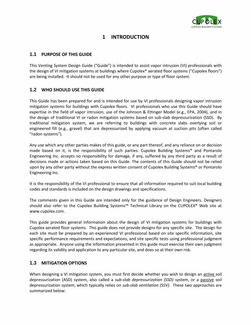
Sub-slab depressurization (SSD): Air is extracted from below the slab (in this case, from the Cupolex void space) so that the air pressure below the slab is lower than in the building (e.g., EPA, 2008). The negative pressure created by an SSD system causes air to flow downwards through the floor slab (through any cracks or openings in the floor slab) rather than upwards into the building, preventing vapor intrusion. SSD generally requires the use of a fan to pull air from under the floor and create negative pressures, resulting in operation and maintenance costs; however, it is also the best way to address high vapor concentrations and is the performance of the system can easily be tested and monitored, by measuring the pressure differential. See Chapter 2 for information related to design of SSD systems using Cupolex floors.
Figure 1. Conceptual diagram of an SSD system.
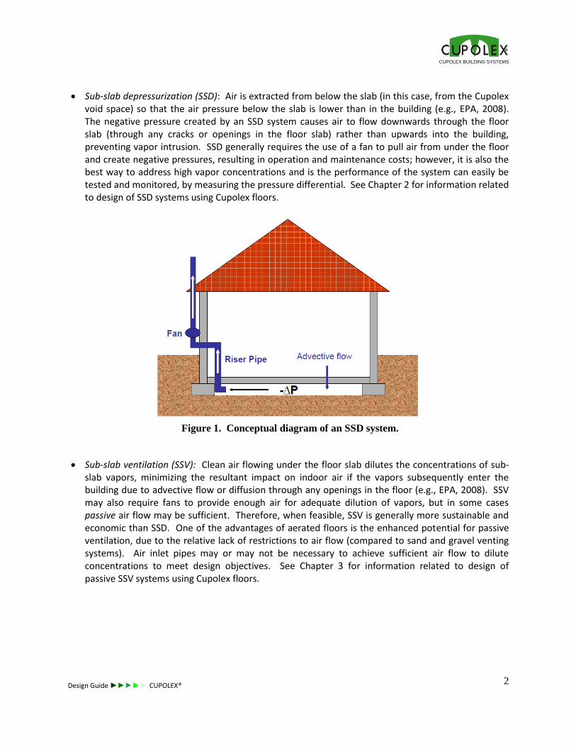
Sub-slab ventilation (SSV): Clean air flowing under the floor slab dilutes the concentrations of sub-slab vapors, minimizing the resultant impact on indoor air if the vapors subsequently enter the building due to advective flow or diffusion through any openings in the floor (e.g., EPA, 2008). SSV may also require fans to provide enough air for adequate dilution of vapors, but in some cases passive air flow may be sufficient. Therefore, when feasible, SSV is generally more sustainable and economic than SSD. One of the advantages of aerated floors is the enhanced potential for passive ventilation, due to the relative lack of restrictions to air flow (compared to sand and gravel venting systems). Air inlet pipes may or may not be necessary to achieve sufficient air flow to dilute concentrations to meet design objectives. See Chapter 3 for information related to design of passive SSV systems using Cupolex floors.
CUPOLEX BUILDING SYSTEMS
Design Guide ►►►►► CUPOLEX®
3
Figure 2. Conceptual diagram of a passive SSV system.
CUPOLEX BUILDING SYSTEMS
Design Guide ►►►►► CUPOLEX®
4
2 SSD SYSTEM DESIGN
This section provides information related to the design of SSD systems at buildings with Cupolex floors, including a discussion of the difference between traditional and Cupolex floor SSD systems, the negative pressure or vacuum level that might be required below the Cupolex floor (or any SSD system slab), the air flow rates that result from negative pressures, the number of suction points required to depressurize the floor, selection of fan size, and why additional liners are not needed with Cupolex floors.
2.1 DIFFERENCE BETWEEN TRADITIONAL & CUPOLEX SYSTEMS
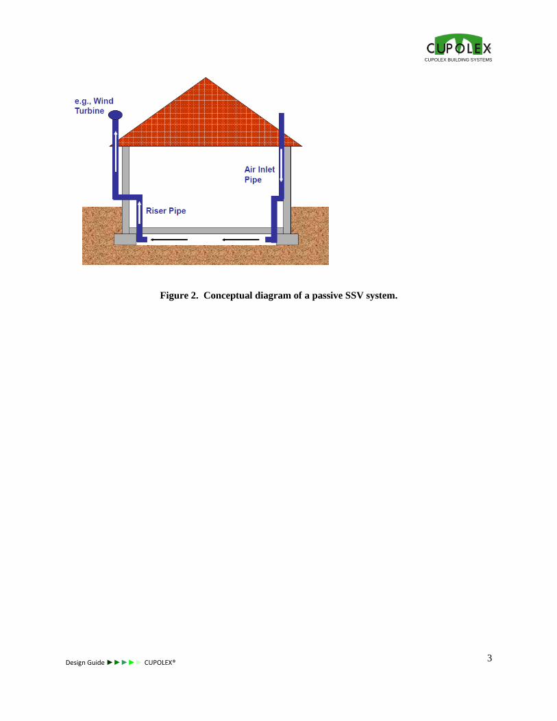
SSD systems with Cupolex floors are very similar to traditional SSD systems with one important difference. Traditional systems require “suction pits” to help depressurize the soil or gravel venting layer below the floor slab, which is resistant to air flow; in the case of Cupolex floors, no suction pits are required, since the entire floor is one large suction pit. Traditional systems must apply sufficient vacuum or negative pressure in the suction pit to overcome the resistance of the gravel to air flow and to extend the negative pressure below the entire floor, resulting in negative pressure distribution or field as shown in Figure 3, below. Negative pressure levels typically drop rapidly with distance from the suction pit, and several suction pits may be required to ensure that the entire floor is adequately depressurized.
Figure 3. Negative pressure field with traditional SSD systems.
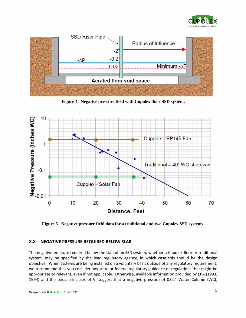
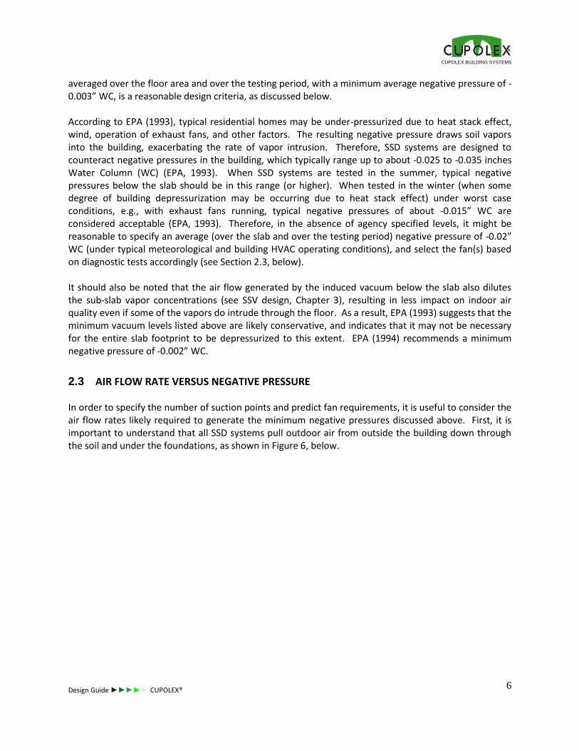
In contrast, because of the very low resistance of the void space below Cupolex floors to air flow (Ove Arup, 1997), a relatively uniform negative pressure field is established below the entire Cupolex floor, as illustrated in Figure 4, below. As a result, lower vacuums can be applied at the riser pipes, allowing the use of smaller and/or fewer fans. Negative pressure data are shown for a traditional system and two Cupolex floor systems in Figure 5, below. Note how the negative pressures drop geometrically with distance from the suction pit for the traditional system, while negative pressures are relatively consistent with distance from the suction points for the two Cupolex floor systems. The second (lower vacuum) Cupolex floor system is actually using a 1.8 watt solar fan to depressurize an 8000 SF building.
Suction Pits
CUPOLEX BUILDING SYSTEMS
Design Guide ►►►►► CUPOLEX®
5
Figure 4. Negative pressure field with Cupolex floor SSD system.
Figure 5. Negative pressure field data for a traditional and two Cupolex SSD systems.
2.2 NEGATIVE PRESSURE REQUIRED BELOW SLAB
The negative pressure required below the slab of an SSD system, whether a Cupolex floor or traditional system, may be specified by the lead regulatory agency, in which case this should be the design objective. When systems are being installed on a voluntary basis outside of any regulatory requirement, we recommend that you consider any state or federal regulatory guidance or regulations that might be appropriate or relevant, even if not applicable. Otherwise, available information provided by EPA (1993, 1994) and the basic principles of VI suggest that a negative pressure of 0.02” Water Column (WC),
CUPOLEX BUILDING SYSTEMS
Design Guide ►►►►► CUPOLEX®
6
averaged over the floor area and over the testing period, with a minimum average negative pressure of -0.003” WC, is a reasonable design criteria, as discussed below. According to EPA (1993), typical residential homes may be under-pressurized due to heat stack effect, wind, operation of exhaust fans, and other factors. The resulting negative pressure draws soil vapors into the building, exacerbating the rate of vapor intrusion. Therefore, SSD systems are designed to counteract negative pressures in the building, which typically range up to about -0.025 to -0.035 inches Water Column (WC) (EPA, 1993). When SSD systems are tested in the summer, typical negative pressures below the slab should be in this range (or higher). When tested in the winter (when some degree of building depressurization may be occurring due to heat stack effect) under worst case conditions, e.g., with exhaust fans running, typical negative pressures of about -0.015” WC are considered acceptable (EPA, 1993). Therefore, in the absence of agency specified levels, it might be reasonable to specify an average (over the slab and over the testing period) negative pressure of -0.02” WC (under typical meteorological and building HVAC operating conditions), and select the fan(s) based on diagnostic tests accordingly (see Section 2.3, below). It should also be noted that the air flow generated by the induced vacuum below the slab also dilutes the sub-slab vapor concentrations (see SSV design, Chapter 3), resulting in less impact on indoor air quality even if some of the vapors do intrude through the floor. As a result, EPA (1993) suggests that the minimum vacuum levels listed above are likely conservative, and indicates that it may not be necessary for the entire slab footprint to be depressurized to this extent. EPA (1994) recommends a minimum negative pressure of -0.002” WC.
2.3 AIR FLOW RATE VERSUS NEGATIVE PRESSURE
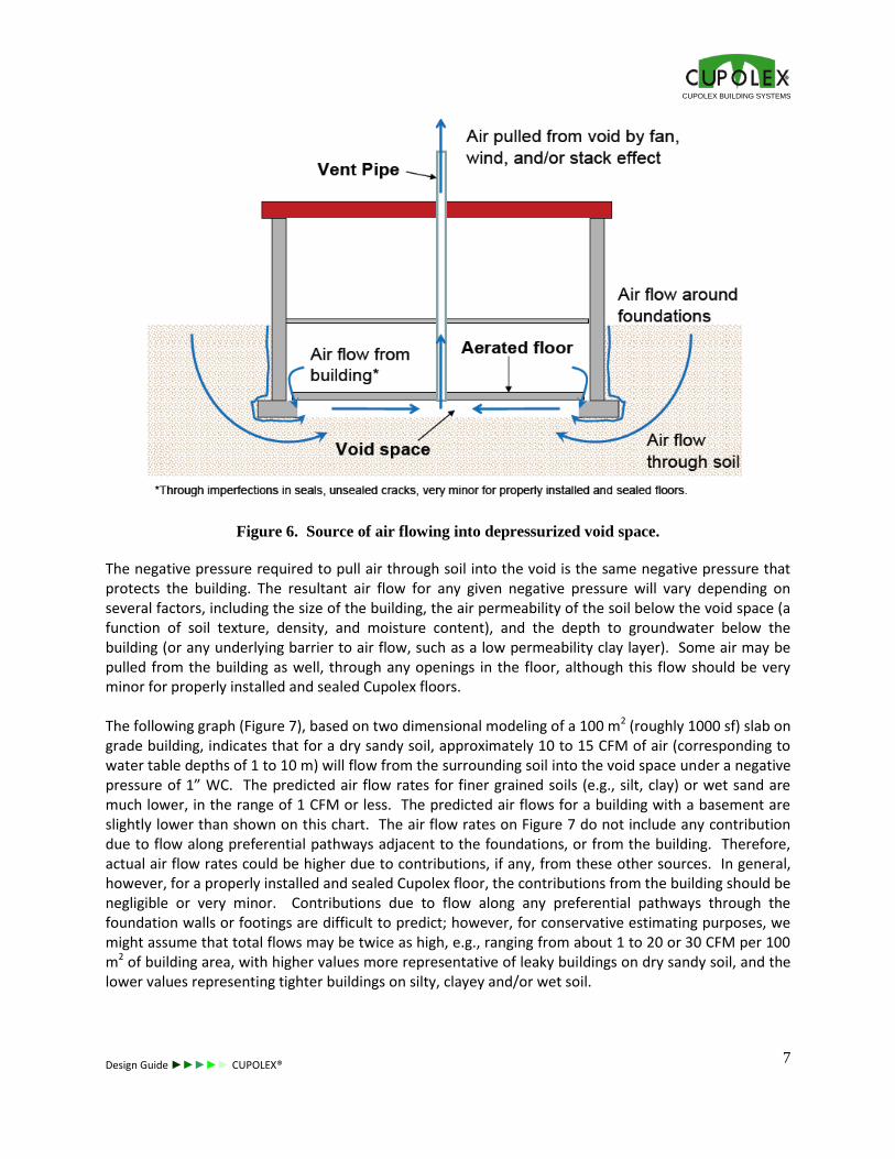
In order to specify the number of suction points and predict fan requirements, it is useful to consider the air flow rates likely required to generate the minimum negative pressures discussed above. First, it is important to understand that all SSD systems pull outdoor air from outside the building down through the soil and under the foundations, as shown in Figure 6, below.
CUPOLEX BUILDING SYSTEMS
Design Guide ►►►►► CUPOLEX®
7
Figure 6. Source of air flowing into depressurized void space.
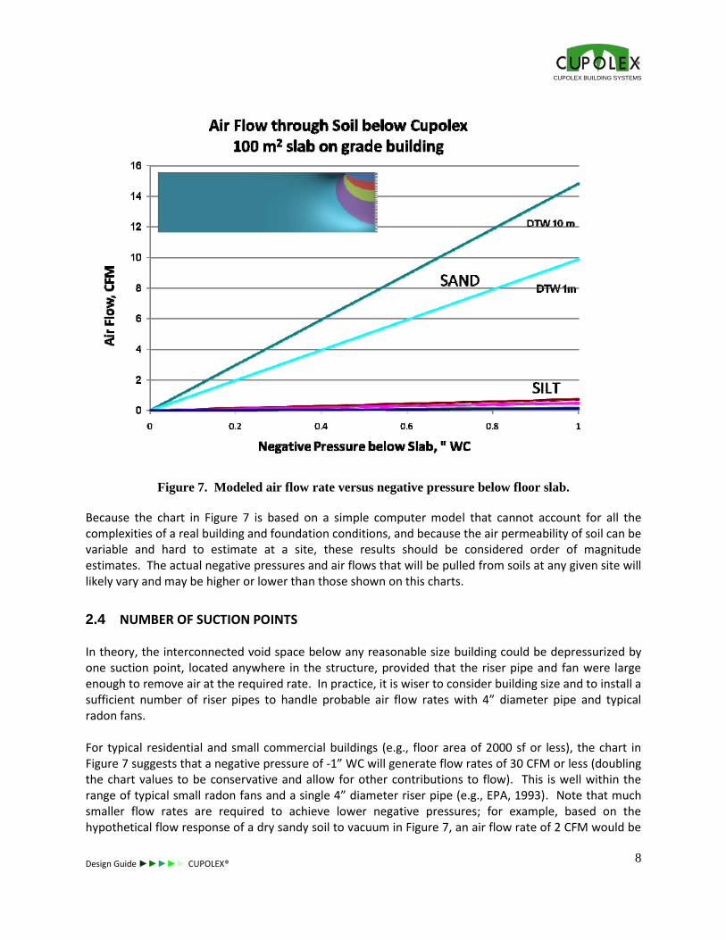
The negative pressure required to pull air through soil into the void is the same negative pressure that protects the building. The resultant air flow for any given negative pressure will vary depending on several factors, including the size of the building, the air permeability of the soil below the void space (a function of soil texture, density, and moisture content), and the depth to groundwater below the building (or any underlying barrier to air flow, such as a low permeability clay layer). Some air may be pulled from the building as well, through any openings in the floor, although this flow should be very minor for properly installed and sealed Cupolex floors. The following graph (Figure 7), based on two dimensional modeling of a 100 m2 (roughly 1000 sf) slab on grade building, indicates that for a dry sandy soil, approximately 10 to 15 CFM of air (corresponding to water table depths of 1 to 10 m) will flow from the surrounding soil into the void space under a negative pressure of 1” WC. The predicted air flow rates for finer grained soils (e.g., silt, clay) or wet sand are much lower, in the range of 1 CFM or less. The predicted air flows for a building with a basement are slightly lower than shown on this chart. The air flow rates on Figure 7 do not include any contribution due to flow along preferential pathways adjacent to the foundations, or from the building. Therefore, actual air flow rates could be higher due to contributions, if any, from these other sources. In general, however, for a properly installed and sealed Cupolex floor, the contributions from the building should be negligible or very minor. Contributions due to flow along any preferential pathways through the foundation walls or footings are difficult to predict; however, for conservative estimating purposes, we might assume that total flows may be twice as high, e.g., ranging from about 1 to 20 or 30 CFM per 100 m2 of building area, with higher values more representative of leaky buildings on dry sandy soil, and the lower values representing tighter buildings on silty, clayey and/or wet soil.
CUPOLEX BUILDING SYSTEMS
Design Guide ►►►►► CUPOLEX®
8
Figure 7. Modeled air flow rate versus negative pressure below floor slab.
Because the chart in Figure 7 is based on a simple computer model that cannot account for all the complexities of a real building and foundation conditions, and because the air permeability of soil can be variable and hard to estimate at a site, these results should be considered order of magnitude estimates. The actual negative pressures and air flows that will be pulled from soils at any given site will likely vary and may be higher or lower than those shown on this charts.
2.4 NUMBER OF SUCTION POINTS
In theory, the interconnected void space below any reasonable size building could be depressurized by one suction point, located anywhere in the structure, provided that the riser pipe and fan were large enough to remove air at the required rate. In practice, it is wiser to consider building size and to install a sufficient number of riser pipes to handle probable air flow rates with 4” diameter pipe and typical radon fans. For typical residential and small commercial buildings (e.g., floor area of 2000 sf or less), the chart in Figure 7 suggests that a negative pressure of -1” WC will generate flow rates of 30 CFM or less (doubling the chart values to be conservative and allow for other contributions to flow). This is well within the range of typical small radon fans and a single 4” diameter riser pipe (e.g., EPA, 1993). Note that much smaller flow rates are required to achieve lower negative pressures; for example, based on the hypothetical flow response of a dry sandy soil to vacuum in Figure 7, an air flow rate of 2 CFM would be
CUPOLEX BUILDING SYSTEMS
Design Guide ►►►►► CUPOLEX®
9
sufficient to achieve a negative pressure of about -0.2” WC, which is ten times higher than the average minimum level of -0.02” WC suggested in Section 2.2. Therefore, unlike traditional systems which need to overcome the resistance of the sand or gravel venting layer, it is not necessary to select a fan for a Cupolex floor that will achieve a negative pressure of -1” WC. For larger buildings where SSD systems are planned, we suggest installing at least one suction point and riser pipe, capable of connection to a fan, for every 4000 to 5000 sf of building area. If diagnostic testing of the system after floor installation indicates that fewer fans are required, the extra riser pipes should be capped and sealed; if left open, these additional riser pipes will increase air flow into the void space and reduce the vacuum that can be generated by any given fan.
2.5 FAN TYPE AND SIZE
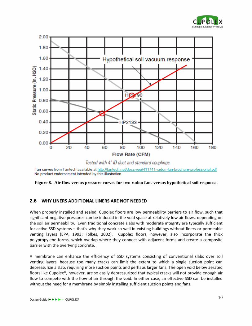
The type, size, and number of fans required to establish the minimum negative pressure in the void space below the Cupolex floor depends on the air flow response of the void space to negative pressure and the fan characteristics (i.e., the relationship between air flow and negative pressure generated by the fan). The response of the void space to negative pressure will depend on site specific soil, moisture, and building conditions and is not easily predicted; therefore, we recommend that final fan selection be based on diagnostic testing of the installed Cupolex floor. Diagnostic testing entails temporary installation of a radon fan on one or more risers pipes (likely stubbed above the floor, if the diagnostic tests are performed shortly after the floor is installed), operation of the fan(s), and measurement of air flow rate at the fan and differential pressures at various points across the floor. This can be done at other riser pipe locations (sealed off) and/or sub-slab probe locations. The size of the fan required can be estimated from the above rule of thumb, i.e., up to 10 to 30 CFM per 1000 sf of Cupolex floor area at a negative pressure of -1” WC, although the flow could be much less, or potentially higher in the case of leaky buildings/foundations and permeable soils. The fans should be operated until a steady state is achieved in the negative pressure and air flow readings; the time required will depend on the size of the void, the air flow rate of the fan (which will decrease as negative pressures develop in the void space) and the air flow rate from the soil into the void (which will increase as negative pressures develop in the void space). For example, assume that a negative pressure of -1” WC generates an air flow rate of 100 cfm below a 10,000 sf building (i.e., 10 cfm per 1000 sf) at steady state. This air flow–vacuum relationship is indicated by the red line on Figure 8, below. Also shown are the characteristic curves for two common radon fans; the points where the fan curves intersect the air flow-vacuum line for the void space represent the equilibrium flow rates and pressure for each fan and the void space. The smaller fan in this case would pull approximately 55 cfm of air at a negative pressure of about 0.55” WC. You should also consider the affect that friction losses in the riser pipe would have on vacuum levels in the void (see EPA, 1993 for friction loss chart based on pipe length, pipe diameter, and flow rate). The fan curves below consider the use of 4” ID pipe and standard couplings, but the length of pipe tested is not indicated.
CUPOLEX BUILDING SYSTEMS
Design Guide ►►►►► CUPOLEX®
10
Figure 8. Air flow versus pressure curves for two radon fans versus hypothetical soil response.
2.6 WHY LINERS ADDITIONAL LINERS ARE NOT NEEDED
When properly installed and sealed, Cupolex floors are low permeability barriers to air flow, such that significant negative pressures can be induced in the void space at relatively low air flows, depending on the soil air permeability. Even traditional concrete slabs with moderate integrity are typically sufficient for active SSD systems – that’s why they work so well in existing buildings without liners or permeable venting layers (EPA, 1993; Folkes, 2002). Cupolex floors, however, also incorporate the thick polypropylene forms, which overlap where they connect with adjacent forms and create a composite barrier with the overlying concrete. A membrane can enhance the efficiency of SSD systems consisting of conventional slabs over soil venting layers, because too many cracks can limit the extent to which a single suction point can depressurize a slab, requiring more suction points and perhaps larger fans. The open void below aerated floors like Cupolex®, however, are so easily depressurized that typical cracks will not provide enough air flow to compete with the flow of air through the void. In either case, an effective SSD can be installed without the need for a membrane by simply installing sufficient suction points and fans.
CUPOLEX BUILDING SYSTEMS
Design Guide ►►►►► CUPOLEX®
11
3 PASSIVE SSV SYSTEM DESIGN
SSV systems rely on air flow to dilute vapor concentrations below the slab and remove VOC mass before it can enter a building. To a certain extent, SSV systems will also reduce air pressures below the slab, reducing the potential for advective flow into the building (like an SSD system). Passive SSV systems rely on natural mechanisms to move air below the slab, including heat stack effects, wind, and solar power. While passive venting will not be sufficient for all buildings, the potential for passive venting is greatly enhanced by the open void of Cupolex floors and its low resistance to air flow. The first step in the design of a passive SSV system is to evaluate the air flow likely needed to reduce VOC concentrations to acceptable levels. The second step is to evaluate the air flow rate that will likely be provided by passive mechanisms, and calculate then the number of riser pipes and passive fans needed to provide this air flow rate. If the number of pipes and passive fans is within reason, then a passive SSV system is potential feasible. All passive SSV system designs, however, should include a contingency for conversion to an active SSD system, if necessary to achieve vapor intrusion mitigation objectives.
3.1 EVALUATION OF VENTING RATE NEEDED
The venting rate required to adequately control vapor intrusion can be evaluated using the Johnson & Ettinger (JE) model (Johnson and Ettinger, 1991), a one-dimensional screening-level model that estimates indoor air concentrations due to both convective and diffusive transport of contaminant vapors into a building located a certain distance above the source of contamination. More information on the use of the JE model to simulate venting rates for SSV systems is provided in the paper by Folkes (2011), available on the Cupolex website. The JE model should only be used by VI professionals who are experienced with its use, using reasonable values for input parameters that tend to err on the conservative side, for sites and conditions where use of the model is not excluded (see EPA, 2004). First, using either the EPA JE spreadsheet model (EPA 2004) or equation (Johnson & Ettinger, 1991), calculate the predicted indoor air concentration for the building, Cb(initial), using site specific VOC concentrations, soil conditions, and building conditions. We suggest using a default value for Qsoil (the rate that soil vapors flow into the building under negative building pressures) of 5 L/min for residential buildings, as recommended by EPA (2004). The Qsoil value should be adjusted, however, for building size. The New Jersey Department of Environmental Protection (NJDEP) recommends scaling Qsoil based on the building perimeter according to the following equation:
Qsoil = 5 L/min * (building perimeter, cm)/(4000 cm) [1]
The resultant indoor air concentration predicted by the JE model is the baseline value for the building, assuming no vapor intrusion mitigation. Second, rerun the JE model, but this time substitute Qtotal for Qsoil, where
Qtotal = Qsoil + Qvent [2]
CUPOLEX BUILDING SYSTEMS
Design Guide ►►►►► CUPOLEX®
12
and where Qvent is the air flow through the Cupolex void introduced by the SSV system. Assume that Qvent is equal to 10 CFM for the first trial. The resultant indoor air concentration using Qtotal will not represent an actual indoor concentration, because it includes the vapor flux that is removed by venting (but the JE model will assume it is directed into the building). We will refer to this indoor air concentration as Cb*. Finally, calculate the actual indoor air concentration resulting from venting or mitigation where:
Cb(mitigated) = Cb* x Qsoil/Qtotal [3]
The reduction in the indoor air concentration from Cb(initial) to Cb(mitigated) is the result of a commensurate reduction in Csoil due to the addition of the venting below the slab, or Qvent. Repeat the above calculations using incrementally higher Qvent values until Cb(mitigated) is at least one order of magnitude lower than the required indoor air concentration. Because the JE model is a screening level model with order of magnitude precision, it is always wise to use conservative input values when running the model. Note that these calculations assume that soil vapors will still flow into the building after mitigation at a rate equal to Qsoil, the same as before mitigation, and that Qsoil is assumed to be a value between 1 and 10 L/min. The reduction in indoor air concentration resulting from SSV according to these calculations is solely due to dilution of the sub-slab vapor concentration (Csoil) due to the introduction of Qvent. This is very conservative, because the Cupolex aerated floor has a lower permeability than standard floors and the resulting value for Qsoil should be much smaller than 1 L/min. Further, the introduction of Qvent will also require a negative pressure to induce the air flow (see SSD design), which may eliminate any advective flow through openings in the floor. It is possible to calculate Cb(mitigated) assuming that Qsoil after mitigation is much smaller than 1 L/min or even zero, but more complex equations (see Johnson & Ettinger, 1991) must be used to account for diffusion through the openings, and Equation 3 will no longer apply. Nevertheless, consideration of more realistic Qsoil values may be desirable to avoid over-conservative results and to explore the potential for passive venting. Contact Cupolex technical support for more information.
3.2 EVALUATION OF PASSIVE VENTING RATES
The feasibility of passive venting will depend on the value of Qvent required to achieve the desired indoor air concentration, as described above, compared to the air flow reasonably provided by passive mechanisms, including heat stack effect, wind turbines, and solar fans, as discussed below.
3.2.1 Venting Due to Heat Stack Effect
The air flow rate due to the heat stack effect can be estimated from the following equation:
Q = 9.4*area pipe*(height of pipe*[sub-slab temperature – outdoor temperature])1/2 [4]
where all values are expressed in feet, second, and Fahrenheit units as applicable. For example, assuming a sub-slab void temperature of 600F; an outdoor air temperature of 200F; a riser vent stack
CUPOLEX BUILDING SYSTEMS
Design Guide ►►►►► CUPOLEX®
13
height of 30 ft; and a 4 inch diameter smooth-walled vent pipe, the estimated air flow rate is approximately 28 cfm. Note that horizontal pipe runs and elbows in the vent pipe will increase the friction loss and air flow rate through the pipe. In addition, air flow due to the heat stack effect will not occur when outside temperatures are higher than the sub-slab temperature. On the other hand, the potential for vapor intrusion is often greatest during colder months, when the heat stack effects are also tending to depressurize the indoor space of buildings.
3.2.2 Venting Using Wind Turbines
Wind turbines can also provide passive ventilation. For example, the Grainger Empire turbine ventilator with a 4” neck diameter is rated at 126 cfm for a 4 mph wind velocity, assuming no resistance to flow. This flow rate will be decreased by friction in the riser pipe and by resistance to the flow of air into the void space through the soil and foundations. Actual wind-induced flow rates, therefore, will be site and building specific and may be substantially lower than the rate under no resistance. For design purposes, we assume an air flow rate of 10 cfm per fan for a 4 mph wind, although this rate is not assured. The potential for wind-induced air flow rates to meet this design level will be enhanced by adding make-up air vents, as described later in this memorandum.
3.2.3 Venting Using Solar Powered Fans
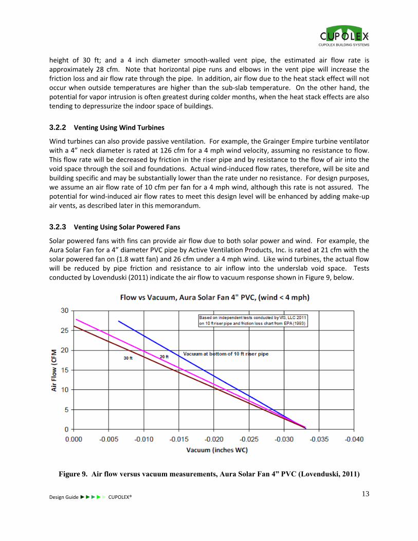
Solar powered fans with fins can provide air flow due to both solar power and wind. For example, the Aura Solar Fan for a 4” diameter PVC pipe by Active Ventilation Products, Inc. is rated at 21 cfm with the solar powered fan on (1.8 watt fan) and 26 cfm under a 4 mph wind. Like wind turbines, the actual flow will be reduced by pipe friction and resistance to air inflow into the underslab void space. Tests conducted by Lovenduski (2011) indicate the air flow to vacuum response shown in Figure 9, below.
Figure 9. Air flow versus vacuum measurements, Aura Solar Fan 4” PVC (Lovenduski, 2011)
CUPOLEX BUILDING SYSTEMS
Design Guide ►►►►► CUPOLEX®
14
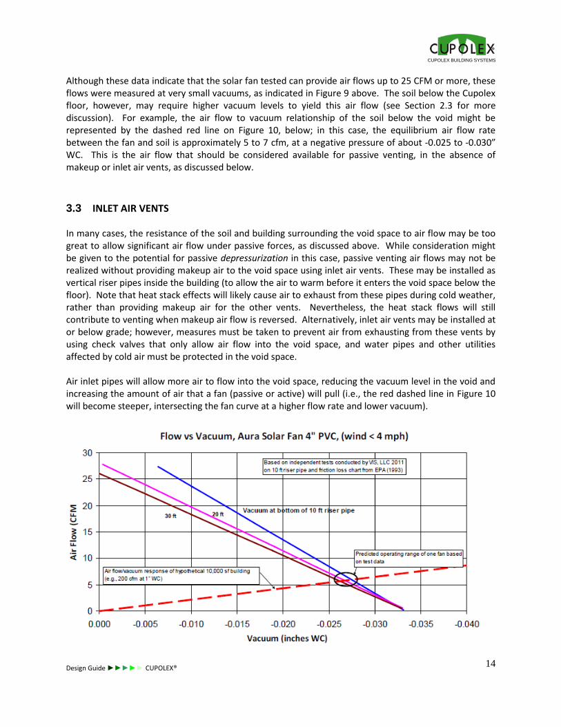
Although these data indicate that the solar fan tested can provide air flows up to 25 CFM or more, these flows were measured at very small vacuums, as indicated in Figure 9 above. The soil below the Cupolex floor, however, may require higher vacuum levels to yield this air flow (see Section 2.3 for more discussion). For example, the air flow to vacuum relationship of the soil below the void might be represented by the dashed red line on Figure 10, below; in this case, the equilibrium air flow rate between the fan and soil is approximately 5 to 7 cfm, at a negative pressure of about -0.025 to -0.030” WC. This is the air flow that should be considered available for passive venting, in the absence of makeup or inlet air vents, as discussed below.
3.3 INLET AIR VENTS
In many cases, the resistance of the soil and building surrounding the void space to air flow may be too great to allow significant air flow under passive forces, as discussed above. While consideration might be given to the potential for passive depressurization in this case, passive venting air flows may not be realized without providing makeup air to the void space using inlet air vents. These may be installed as vertical riser pipes inside the building (to allow the air to warm before it enters the void space below the floor). Note that heat stack effects will likely cause air to exhaust from these pipes during cold weather, rather than providing makeup air for the other vents. Nevertheless, the heat stack flows will still contribute to venting when makeup air flow is reversed. Alternatively, inlet air vents may be installed at or below grade; however, measures must be taken to prevent air from exhausting from these vents by using check valves that only allow air flow into the void space, and water pipes and other utilities affected by cold air must be protected in the void space. Air inlet pipes will allow more air to flow into the void space, reducing the vacuum level in the void and increasing the amount of air that a fan (passive or active) will pull (i.e., the red dashed line in Figure 10 will become steeper, intersecting the fan curve at a higher flow rate and lower vacuum).
CUPOLEX BUILDING SYSTEMS
Design Guide ►►►►► CUPOLEX®
15
Figure 10. Comparison of solar fan curves to hypothetical air flow/vacuum curve for void space.
3.4 NUMBER OF PASSIVE RISER PIPES AND FANS REQUIRED
The number of passive system riser pipes and fans (e.g., wind turbines, solar fans) needed to achieve passive system design objectives can be approximated by dividing the total air flow required (Qvent) by the estimated air flow per riser pipe, as discussed above. We recommend basing this calculation on conservative (high) estimates of the air flow required to meet indoor air screening levels, and conservative (low) estimates of the air flow that can be provided by each riser pipe and/or passive fan. If the number of riser pipes and fans (including air inlet vents, if needed) is reasonable, then a passive SSV system may be viable.
3.5 ACTIVE SYSTEM CONTINGENCY
Passive venting system designs should include a contingency for conversion to an active system if diagnostic, verification, or other tests indicate that passive venting is not sufficient to meet indoor air screening levels. The following contingent actions should be specified:
diagnostic testing of the aerated floor to select an appropriately sized fan or fans to achieve average and minimum negative pressures specified by applicable regulations, guidance, or industry standards, as applicable;
installation of the selected fan(s); and
confirmation of average and minimum negative pressures below the floor under typical HVAC operating and meteorological conditions.
Please note that we recommend that VI professionals never guarantee or represent that a passive system will be adequate based on design evaluations. The JE model used to estimate the vapor intrusion potential of the building, with and without venting, is a screening level model that is imprecise and cannot fully represent real world conditions (e.g., Johnson and Ettinger, 1991; EPA, 2004, and others). In addition, the actual air flow to vacuum behavior of any Cupolex floor void will depend on site soil, moisture, and building conditions that cannot be precisely estimated in advance. The actual potential for passive venting to succeed can only be verified by post-construction tests and monitoring; however, the potential for passive venting to succeed is far greater with a Cupolex floor than it is with a traditional system.
CUPOLEX BUILDING SYSTEMS
Design Guide ►►►►► CUPOLEX®
16
4 OTHER SYSTEM COMPONENTS
The other components of and considerations for a Cupolex aerated floor SSD or SSV system are similar to those for traditional radon systems; therefore, guidance and accepted good industry practices for typical SSD systems should be followed (e.g., EPA, 1993, EPA, 1994, ASTM E1465). The following sections highlight certain aspects of the venting system that are important for system performance, including the number and location of suction points, air transfer pipes across grade beams and interior footings, sealing of floor penetrations, riser pipes, and building codes.
4.1 SUCTION POINTS
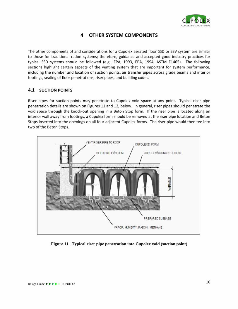
Riser pipes for suction points may penetrate to Cupolex void space at any point. Typical riser pipe penetration details are shown on Figures 11 and 12, below. In general, riser pipes should penetrate the void space through the knock-out opening in a Beton Stop form. If the riser pipe is located along an interior wall away from footings, a Cupolex form should be removed at the riser pipe location and Beton Stops inserted into the openings on all four adjacent Cupolex forms. The riser pipe would then tee into two of the Beton Stops.
Figure 11. Typical riser pipe penetration into Cupolex void (suction point)
CUPOLEX BUILDING SYSTEMS
Design Guide ►►►►► CUPOLEX®
17
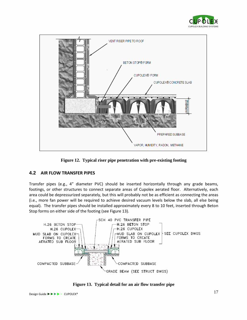
Figure 12. Typical riser pipe penetration with pre-existing footing
4.2 AIR FLOW TRANSFER PIPES
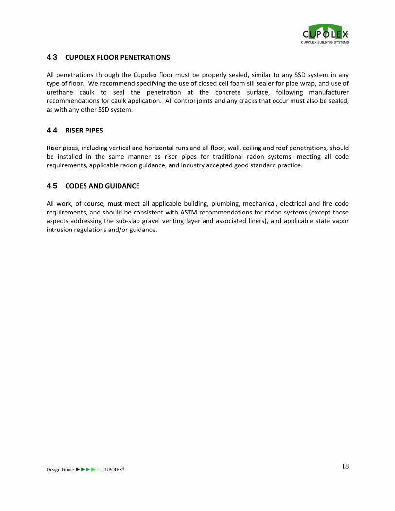
Transfer pipes (e.g., 4” diameter PVC) should be inserted horizontally through any grade beams, footings, or other structures to connect separate areas of Cupolex aerated floor. Alternatively, each area could be depressurized separately, but this will probably not be as efficient as connecting the areas (i.e., more fan power will be required to achieve desired vacuum levels below the slab, all else being equal). The transfer pipes should be installed approximately every 8 to 10 feet, inserted through Beton Stop forms on either side of the footing (see Figure 13).
Figure 13. Typical detail for an air flow transfer pipe
CUPOLEX BUILDING SYSTEMS
Design Guide ►►►►► CUPOLEX®
18
4.3 CUPOLEX FLOOR PENETRATIONS
All penetrations through the Cupolex floor must be properly sealed, similar to any SSD system in any type of floor. We recommend specifying the use of closed cell foam sill sealer for pipe wrap, and use of urethane caulk to seal the penetration at the concrete surface, following manufacturer recommendations for caulk application. All control joints and any cracks that occur must also be sealed, as with any other SSD system.
4.4 RISER PIPES
Riser pipes, including vertical and horizontal runs and all floor, wall, ceiling and roof penetrations, should be installed in the same manner as riser pipes for traditional radon systems, meeting all code requirements, applicable radon guidance, and industry accepted good standard practice.
4.5 CODES AND GUIDANCE
All work, of course, must meet all applicable building, plumbing, mechanical, electrical and fire code requirements, and should be consistent with ASTM recommendations for radon systems (except those aspects addressing the sub-slab gravel venting layer and associated liners), and applicable state vapor intrusion regulations and/or guidance.
CUPOLEX BUILDING SYSTEMS
Design Guide ►►►►► CUPOLEX®
19
5 POST-CONSTRUCTION INSPECTIONS AND TESTING
Construction quality assurance should be provided to ensure that the components of the Cupolex floor venting system are installed and function as expected, including inspection of riser pipes, inspection and testing of seals around all pipes and other floor penetrations, sealing of all control joints and any observed cracks in the concrete, testing of fans, measurement of negative pressures (for SSD systems) under as-built conditions, and testing of any monitoring and alarm systems.
5.1 LEAK TESTING
The integrity of the Cupolex floor slab seals should be tested after the concrete has been poured and set, by placing the void space below the floor under a temporary vacuum and checking for air leaks in the overlying slab. This can be done at the same time diagnostic tests are performed for SSD fan selection, if applicable. The Contractor installing the Cupolex floor slab should be made responsible for sealing any leaks in the slab detected.
5.2 VERIFICATION TESTING
Many agencies require verification testing (i.e., indoor air testing) after VI mitigation systems are in operation (and the building is enclosed) to verify the effectiveness of the system. We also encourage this, regardless of agency requirements, to ensure that the active SSD or passive SSV system is performing as expected. In the case of this passive venting system, the purpose of the indoor air testing would also be to determine the need for converting to an active system. The performance of SSD systems should also be verified by measuring negative pressures at various points across the floor to ensure that design objectives are being met. In some jurisdictions, demonstration of adequate negative pressures across the entire floor may obviate the need for indoor air testing. This is much easier to demonstrate with Cupolex floors, which typically will have relatively uniform negative pressures across the building, than it is with traditional systems, where the negative pressures are typically variable and less reliable. Because passive SSV systems rely on ventilation rather than depressurization to achieve design objectives, there should be no negative pressure requirements for system performance, although some depressurization due to venting is expected (and should be documented). Air flow rates and pressures can be measured in the vent riser pipes to document that passive venting is occurring at the time of verification testing. If indoor air testing indicates that concentrations exceed applicable action levels and a line of evidence evaluation indicates that the source is vapor intrusion and not an indoor or outdoor air source, then one or more suitably sized electric fans should be installed to convert the passive venting system to an active system, as described above.

CUPOLEX BUILDING SYSTEMS
Design Guide ►►►►► CUPOLEX®
21
NOTES