


Languages
Pages
Legal


www. .comwww. .com
your reliable partner
P.9110.V02.EN
ROBA®-DS 9110 / 9210

your reliable partner
ROBA®-DS – The backlash-free, torsionally rigid shaft coupling for HBM torque transducers
Characteristics and Advantages• High precision and reliability
• Optimum running smoothness
• High speeds
• Robust and highly dynamic
• Different designs for optimum set-up
Function ROBA®-DS disk pack couplings compensate for axial, radial and angular shaft misalignments. Torque measurement flanges are precision transducers, using which the measurement of extremely small measurement uncertainties can be realised. However, for this purpose several prerequisites are necessary. One of the most important prerequisites is the minimisation of the parasitic loads affecting the transducer, which amongst other things are caused by alignment errors in the drive line. The use of the ROBA®-DS as a torsionally rigid and backlash-free compensating coupling provides the optimum prerequisites in order to achieve exact measurement results of the torque transducer.
Design ROBA®-DS disk pack couplings of the type series 9110 and 9210 are especially adapted for the attachment of HBM torque transducers. Different types of construction and flexible combination possibilities permit the integration of measurement flanges in almost every test stand and drive constellation (see the Installation and Operational Instructions B.9110._ _).
Constructional Designs
Standard constructional designs – Type 9110._
Preferred type of construction (external shrink disk hub)
Type of construction, internal shrink disk hub Sandwich construction
Compact design
When the set-up of the measurement line from the load side is only possible via a shrink disk hub with internal clamping
Type of construction with maximum shaft misalignment compensation
whilst simultaneously being the shortest possible type of construction
Low mass moment of inertia design Higher mass moment of inertia compared to the “Preferred type of construction”
Quick installationComplex installation in comparison to the “Preferred type of construction”
as a result of the intermediate flange required
External clamping of the shrink disks - External clamping of the shrink disks
Preferred variant is the shortest and most rigid design.
The couplings are balanced according to DIN ISO 1940 to a balance quality of G 2.5 at n = 3000 rpm.
High-speed constructional design for high speeds – Type 9210._
The individual parts are manufactured to a high level of accuracy (Quality IT5), with restricted shaft run-out and axial run-out tolerance.
The couplings are balanced according to DIN ISO 1940 to a balance quality of G 2.5 at n = 5000 rpm.2

your reliable partner
Assignment of the Torque Transducers
The “internal shrink disk hub” construction and the “sandwich construction” are not possible for the previous model, the torque transducer Type T40.This restriction does not apply to the torque transducer Type T40B.
Measurement flange company HBM ROBA®-DS Size
TB2
100 Nm 16 F
200 Nm 16
500 Nm 64
1000 Nm 64
2000 Nm 300
3000 Nm 300
5000 Nm 500
10,000 Nm 850
T12HP
(T12)
(T10FS)
100 Nm 16 F
200 Nm 16
500 Nm 64
1000 Nm 64
2000 Nm 300
3000 Nm 300
5000 Nm 500
10,000 Nm 850
T40B
(T40)
50 Nm 16 F
100 Nm 16 F
200 Nm 16
500 Nm 64
1000 Nm 64
2000 Nm 300
3000 Nm 300
5000 Nm 500
10,000 Nm 850
T10F 50 to 10,000 Nm on request
T40HS 100 to 3000 Nm on request
T40MS 500 to 2000 Nm on request
T40FM 15,000 to 80,000 Nm on request 1) 2)
T40FH 100,000 to 300,000 Nm on request 1) 2)
1) In this torque range, the shaft coupling must be assigned according to the application.
2) See pages 12 – 13
Contents
Assignment of the torque transducers Page 3
Shrink disk hubs Page 4Frictionally-locking transmittable torques Page 4
Standard constructional designs Type 9110._ Page 5Preferred type of construction (external shrink disk hub) Page 5Type of construction, internal shrink disk hub Page 6Sandwich construction Page 7Dimensions of the components Page 8
High-speed constructional design Type 9210._ Page 10Dimensions of the components Page 11
Module according to former HBM ID. number 1-4411.011_ Page 11
ROBA®-DS for high torques – Sizes 2200 to 11000 Page 12ROBA®-DS for high Torques – Measurement flange variants Page 13
Technical explanations Page 14
3
Ød
Ød
Ød
your reliable partner
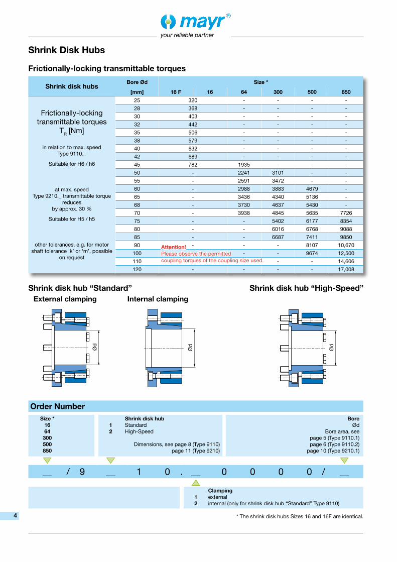
Shrink Disk Hubs
Order NumberSize *
1664300500850
12
Shrink disk hubStandardHigh-Speed
Dimensions, see page 8 (Type 9110)page 11 (Type 9210)
BoreØd
Bore area, see page 5 (Type 9110.1) page 6 (Type 9110.2)
page 10 (Type 9210.1)
__ / 9 __ 1 0 . __ 0 0 0 0 / __
12
Clampingexternalinternal (only for shrink disk hub “Standard” Type 9110)
Shrink disk hub “Standard”External clamping Internal clamping
Shrink disk hub “High-Speed”
* The shrink disk hubs Sizes 16 and 16F are identical.
Frictionally-locking transmittable torques
Shrink disk hubsBore Ød Size *
[mm] 16 F 16 64 300 500 850
Frictionally-locking transmittable torques
TR [Nm]
in relation to max. speed Type 9110._
Suitable for H6 / h6
at max. speedType 9210._ transmittable torque
reduces by approx. 30 %
Suitable for H5 / h5
other tolerances, e.g. for motor shaft tolerance ‘k’ or ‘m’, possible
on request
25 320 - - - -
28 368 - - - -
30 403 - - - -
32 442 - - - -
35 506 - - - -
38 579 - - - -
40 632 - - - -
42 689 - - - -
45 782 1935 - - -
50 - 2241 3101 - -
55 - 2591 3472 - -
60 - 2988 3883 4679 -
65 - 3436 4340 5136 -
68 - 3730 4637 5430 -
70 - 3938 4845 5635 7726
75 - - 5402 6177 8354
80 - - 6016 6768 9088
85 - - 6687 7411 9850
90 - - - 8107 10,670
100 - - 9674 12,500
110 - - 14,606
120 - - - - 17,008
Attention! Please observe the permitted coupling torques of the coupling size used.
4

your reliable partner
Technical Data ROBA®-DS Size 16 F 16 64 300 500 850Nominal torque TKN [Nm] 190 300 1100 3500 5800 10,000Peak torque 1) TKS [Nm] 285 450 1650 5250 8700 14,250Oscillation range acc. DIN 50100 (peak - peak) TKSB [Nm] 380 600 2200 7000 11,600 20,000Outer diameter D [mm] 102 102 132 178 210 252Minimum hub bore d min [mm] 25 H6 25 H6 45 H6 50 H6 60 H6 70 H6Maximum hub bore d max [mm] 45 H6 45 H6 70 H6 85 H6 100 H6 120 H6Maximum speed 2) n max [rpm] 18,000 18,000 15,000 12,000 10,000 8000
Permitted misalignments
Perm. angular misalignment 3) ∆Kw [°] 1.0 0.7 0.6 0.5 0.5 0.5Perm. axial displacement 4) ∆Ka [mm] 1.1 0.8 1.1 1.2 1.4 1.6
Perm. radial misalignment 4)
Module 1, connection plate ∆KVP [mm] 0.30 0.20 0.25 0.25 0.35 0.40Module 1, sleeve ∆KHL [mm] 1.0 0.7 1.0 1.25 1.35 1.7
Spring Rigidities
Torsion 4)Module 1, connection plate CT VP [103 Nm/rad] 72.5 90 600 1740 5950 10,300Module 1, sleeve CT HL [103 Nm/rad] 65 78.5 463 1176 3312 5006
Angular spring rigidity 3) Cw [Nm/rad] 229 285 1850 6980 11,250 18,580Axial spring rigidity 3) Ca [N/mm] 235 525 1325 1400 1195 2640
Mass moments of inertia
Shrink disk hub, external clamping (with max. bore) [10-3 kgm2] 1.53 1.53 8.49 34.47 81.00 203.74Module 1, connection plate [10-3 kgm2] 1.86 1.85 10.78 50.46 110.42 274.68Module 1, sleeve [10-3 kgm2] 2.19 2.18 14.04 68.70 150.99 369.21
WeightsShrink disk hub, external clamping (with max. bore) [kg] 1.16 1.16 3.34 8.03 13.36 23.36Module 1, connection plate [kg] 1.44 1.43 4.06 11.51 17.49 30.03Module 1, sleeve [kg] 1.77 1.76 5.31 15.77 24.50 42.99
1) Valid for unchanging load direction, max. load cycle ≤ 105
2) For speeds of more than 5000 rpm, a limitation of the misalignment to max. 30 % is necessary.
3) The values refer to 1 disk pack.4) The values refer to couplings with 2 disk packs.
Order NumberSize16 Fto
850
Hub side 1Without
Shrink disk hub, external clamping
01
01
Hub side 2WithoutShrink disk hub, external clamping
Boreside 1
Ød
Boreside 2
Ød
__ / 9 1 1 0 . __ __ __ 0 0 / __ / __
Attachment measurement flange side 1Module 1, connection plate **
Module 1, sleeve12
Preferred Type of Construction (External Shrink Disk Hub)
Module 1, sleeve
Torque transducer
Shrink disk hub, external clamping
Module 1, connection plate ** Shrink disk hub, external clamping
Without hub
Without hub
Side 1 Side 2
Preferred variant *
* The “preferred variant” is the shortest and most rigid design.** Does not correspond to the former HBM ID. number 1-4411.011_ (see page 11)
Standard design Type 9110._ _ _00
The depicted connection screws are included in delivery.The screws for the left flange of the torque transducer
are not included in delivery.
The shrink disk hub (side 1) with module 1 is supplied as a finished assembly.
5

your reliable partner
Order NumberSize16 Fto
850
Hub side 1Without
Shrink disk hub, internal clamping
02
01
Hub side 2WithoutShrink disk hub, external clamping
Boreside 1
Ød
Boreside 2
Ød
__ / 9 1 1 0 . __ __ 0 __ 0 / __ / __
12
Attachment measurement flange side 2Module 2, connection plate Module 2, sleeve
Module 2, sleeve
Module 2, connection plate
Shrink disk hub, internal clamping
Shrink disk hub, external clamping
Without hub
Without hub
Type of Construction, Internal Shrink Disk Hub
Torque transducer
Side 1 Side 2
Technical Data ROBA®-DS Size 16 F 16 64 300 500 850Nominal torque TKN [Nm] 190 300 1100 3500 5800 10,000Peak torque 1) TKS [Nm] 285 450 1650 5250 8700 14,250Oscillation range acc. DIN 50100 (peak - peak) TKSB [Nm] 380 600 2200 7000 11,600 20,000Outer diameter D [mm] 102 102 132 178 210 252Minimum hub bore d min [mm] 25 H6 25 H6 45 H6 50 H6 60 H6 70 H6Maximum hub bore d max [mm] 45 H6 45 H6 70 H6 85 H6 100 H6 120 H6Maximum speed 2) n max [rpm] 18,000 18,000 15,000 12,000 10,000 8000
Permittedmisalignments
Perm. angular misalignment 3) ∆Kw [°] 1.0 0.7 0.6 0.5 0.5 0.5Perm. axial displacement 4) ∆Ka [mm] 1.1 0.8 1.1 1.2 1.4 1.6Perm. radial misalignment 4)
Module 2, connection plate ∆KVP [mm] 0.30 0.20 0.25 0.25 0.35 0.40Module 2, sleeve ∆KHL [mm] 1.0 0.7 1.0 1.25 1.35 1.7
Spring Rigidities
Torsion 4) Module 2, connection plate CT VP [103 Nm/rad] 72.5 90 600 1740 5950 10,300Module 2, sleeve CT HL [103 Nm/rad] 65 78.5 463 1176 3312 5006
Angular spring rigidity 3) Cw [Nm/rad] 229 285 1850 6980 11,250 18,580Axial spring rigidity 3) Ca [N/mm] 235 525 1325 1400 1195 2640
Mass moments of inertia
Shrink disk hub, external clamping (with max. bore) [10-3 kgm2] 1.53 1.53 8.49 34.47 81.00 203.74Shrink disk hub, internal clamping (with max. bore) [10-3 kgm2] 1.51 1.51 8.03 32.33 78.33 198.19Module 2, connection plate [10-3 kgm2] 7.73 7.72 31.46 77.37 233.86 540.13Module 2, sleeve [10-3 kgm2] 8.07 8.06 34.71 130.96 274.43 634.67
Weights
Shrink disk hub, external clamping (with max. bore) [kg] 1.16 1.16 3.34 8.03 13.36 23.36Shrink disk hub, internal clamping (with max. bore) [kg] 1.17 1.17 3.16 7.55 12.94 22.65Module 2, connection plate [kg] 3.78 3.77 9.18 20.32 31.19 50.27Module 2, sleeve [kg] 4.11 4.10 10.43 24.62 38.20 63.22
1) Valid for unchanging load direction, max. load cycle ≤ 105
2) For speeds of more than 5000 rpm, a limitation of the misalignment to max. 30 % is necessary.
3) The values refer to 1 disk pack.4) The values refer to couplings with 2 disk packs.
Standard design Type 9110._ _0_0
The module 2 with shrink disk hub (side 2) is supplied as a finished assembly.
The depicted connection screws are included in delivery.The screws for the left flange of the torque transducer
are not included in delivery.
6

your reliable partner
Module 1, single joint
Module 2, single joint
Shrink disk hub, external clamping
Shrink disk hub, external clamping
Order NumberSize16 Fto
850
Hub side 1Without
Shrink disk hub, external clamping
01
01
Hub side 2WithoutShrink disk hub, external clamping
Boreside 1
Ød
Boreside 2
Ød
__ / 9 1 1 0 . __ __ 3 3 0 / __ / __
Without hub
Without hub
Sandwich Construction
Torque transducer
Side 1 Side 2
Technical Data ROBA®-DS Size 16 F 16 64 300 500 850Nominal torque TKN [Nm] 190 300 1100 3500 5800 10,000Peak torque 1) TKS [Nm] 285 450 1650 5250 8700 14,250Oscillation range acc. DIN 50100 (peak - peak) TKSB [Nm] 380 600 2200 7000 11,600 20,000Outer diameter D [mm] 102 102 132 178 210 252Minimum hub bore d min [mm] 25 H6 25 H6 45 H6 50 H6 60 H6 70 H6Maximum hub bore d max [mm] 45 H6 45 H6 70 H6 85 H6 100 H6 120 H6Maximum speed 2) n max [rpm] 18,000 18,000 15,000 12,000 10,000 8000
Permittedmisalignments
Perm. angular misalignment 3) ∆Kw [°] 1.0 0.7 0.6 0.5 0.5 0.5Perm. axial displacement 4) ∆Ka [mm] 1.1 0.8 1.1 1.2 1.4 1.6Perm. radial misalignment 4) 5) ∆Kr [mm] 1.6 1.1 1.1 1.1 1.3 1.5
Spring RigiditiesTorsion 4) Modules 1 and 2 6) CT [103 Nm/rad] 72.5 90 600 1740 5950 10,300Angular spring rigidity 3) Cw [Nm/rad] 229 285 1850 6980 11,250 18,580Axial spring rigidity 3) Ca [N/mm] 235 525 1325 1400 1195 2640
Mass moments of inertia
Shrink disk hub, external clamping (with max. bore) [10-3 kgm2] 1.53 1.53 8.49 34.47 81.00 203.74Module 1, single joint [10-3 kgm2] 1.37 1.37 6.52 31.92 71.86 177.88Module 2, single joint [10-3 kgm2] 7.24 7.24 27.20 94.14 195.30 443.34
WeightsShrink disk hub, external clamping (with max. bore) [kg] 1.16 1.16 3.34 8.03 13.36 23.36Module 1, single joint [kg] 0.96 0.96 2.35 7.35 11.11 19.46Module 2, single joint [kg] 3.30 3.30 7.48 16.19 24.81 39.69
1) Valid for unchanging load direction, max. load cycle ≤ 105
2) For speeds of more than 5000 rpm, a limitation of the misalignment to max. 30 % is necessary.
3) The values refer to 1 disk pack.
4) The values refer to couplings with 2 disk packs.5) The values refer to the length of the measurement flange T40B. 6) The torque transducer is not taken into consideration.
Standard design Type 9110._ _330
The shrink disk hub (side 1) with module 1 and module 2 with the shrink disk hub (side 2) are supplied as finished assemblies respectively.
The depicted connection screws are included in delivery.The screws for the left flange of the torque transducer
are not included in delivery.
7
l2
ØD
1
ØT K
ØZ
A
b2
f2
Ød
Ød 2
a
l1
ØD
1
ØT K
ØZ
1
k
b1
f1
Ød
Ød 2
a
U1U2 U2
L2
ØD
ØT K
ØZ
A
f S f
a
H1U2 U2
L1
ØD
ØT K
ØZ
A
f S f
a
your reliable partner
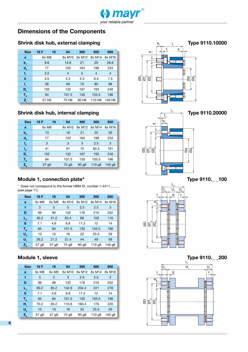
Module 1, sleeve
Size 16 F 16 64 300 500 850
a 6x M8 6x M8 8x M10 8x M12 8x M14 8x M16
f 3 3 3 2.5 2.5 3
D 99 99 132 178 210 252
L1 90.2 85.2 142.6 204.4 221 278
S 7.1 4.6 6.8 11.2 12 14
TK 84 84 101.5 130 155.5 196
H1 70.2 65.2 110.6 160.4 170 220
U2 10 10 16 22 25.5 29
ZA 57 g6 57 g6 75 g6 90 g6 110 g6 140 g6
Shrink disk hub, external clamping
Shrink disk hub, internal clamping
Module 1, connection plate*
Size 16 F 16 64 300 500 850
a 6x M8 8x M10 8x M12 8x M14 8x M16
b1 9.6 14.6 21 20 26.6
d2 77 120 164 198 234
f1 3.5 4 5 4 4
k 3.5 5.3 5.3 6.4 7.5
l1 38 58 70 80 98
D1 102 132 167 193 240
TK 84 101.5 130 155.5 196
Zi 57 H6 75 H6 90 H6 110 H6 140 H6
Size 16 F 16 64 300 500 850
a 6x M8 8x M10 8x M12 8x M14 8x M16
b2 13 16 21 25 30
d2 77 120 164 198 234
f2 3 3 3 2.5 3
l2 41 61 72 82.5 101
D1 102 132 167 193 240
TK 84 101.5 130 155.5 196
ZA 57 g6 75 g6 90 g6 110 g6 140 g6
Size 16 F 16 64 300 500 850
a 6x M8 6x M8 8x M10 8x M12 8x M14 8x M16
f 3 3 3 2.5 2.5 3
D 99 99 132 178 210 252
L2 46.2 41.2 63.4 88 100 116
S 7.1 4.6 6.8 11.2 12 14
TK 84 84 101.5 130 155.5 196
U2 10 10 16 22 25.5 29
U1 26.2 21.2 31.4 44 49 58
ZA 57 g6 57 g6 75 g6 90 g6 110 g6 140 g6
* Does not correspond to the former HBM ID. number 1-4411._ _ _ _ (see page 11)
Type 9110._ _200
Type 9110._ _100
Type 9110.20000
Type 9110.10000
Dimensions of the Components
8

U1U3b3 U2
L3
ØD
ØT K
ØZ
A
f3 S f
a
ØZ
i
ØT K
ØD
3
a
f4
ØD
2H1U3b3 U2
L4
ØD
ØT K
ØZ
A
f3 S f
a
ØZ
i
ØT K
a
ØD
3
ØD
2
f4
U3b3 U2
U5
ØD
ØT K
ØZ
A
f3 S f
a
ØZ
i
ØT K
ØD
2
a
U2 U2
U4
ØT K
ØZ
A
f S f
a
ØZ
A
ØT K
a
ØD
3
f4
your reliable partner
Module 2, connection plate
Module 2, sleeve
Module 1, single joint / module 2, single joint for integrated measurement flange
Type 9110._ _010
Type 9110._ _020
Type 9110._ _330
Size 16 F 16 64 300 500 850a 6x M8 6x M8 8x M10 8x M12 8x M14 8x M16b3 12 12 13,5 19 19 24f 3 3 3 2,5 2,5 3f3 4 4 5 3 3,5 6f4 9,5 9,5 7,5 7 7 7D 99 99 132 178 210 252D2 132 132 170 220 250 300D3 102 102 130 164 188 240L3 69,7 64,7 89,5 113,5 132 145S 7,1 4,6 6,8 11,2 12 14TK 84 84 101,5 130 155,5 196U1 26,2 21,2 31,4 44 49 58U2 10 10 16 22 25,5 29U3 33,5 33,5 42,1 47,5 57,5 58ZA 57 g6 57 g6 75 g6 90 g6 110 g6 140 g6Zi 57 H6 57 H6 75 H6 90 H6 110 H6 140 H6
Size 16 F 16 64 300 500 850a 6x M8 6x M8 8x M10 8x M12 8x M14 8x M16b3 12 12 13,5 19 19 24f 3 3 3 2,5 2,5 3f3 4 4 5 4 3,5 6f4 9,5 9,5 7,5 7 7 7D 99 99 132 178 210 252D2 132 132 170 220 250 300D3 102 102 130 164 188 240H1 70,2 65,2 110,6 160,4 170 220L4 113,7 108,7 168,7 229,9 253 307S 7,1 4,6 6,8 11,2 12 14TK 84 84 101,5 130 155,5 196U2 10 10 16 22 25,5 29U3 33,5 33,5 42,1 47,5 57,5 58ZA 57 g6 57 g6 75 g6 90 g6 110 g6 140 g6Zi 57 H6 57 H6 75 H6 90 H6 110 H6 140 H6
Size 16 F 16 64 300 500 850a 6x M8 6x M8 8x M10 8x M12 8x M14 8x M16b3 12 12 13,5 19 19 24f 3 3 3 2,5 2,5 3f3 4 4 5 4 3,5 6f4 9,5 9,5 7,5 7 7 7D 99 99 132 178 210 252D2 132 132 170 220 250 300D3 102 102 130 164 188 240S 7,1 4,6 6,8 11,2 12 14TK 84 84 101,5 130 155,5 196U2 10 10 16 22 25,5 29U3 33,5 33,5 42,1 47,5 57,5 58U4 27,1 24,6 38,8 55,2 63 72U5 50,6 48,1 64,9 80,7 95 101ZA 57 g6 57 g6 75 g6 90 g6 110 g6 140 g6Zi 57 H6 57 H6 75 H6 90 H6 110 H6 140 H6 9
your reliable partner
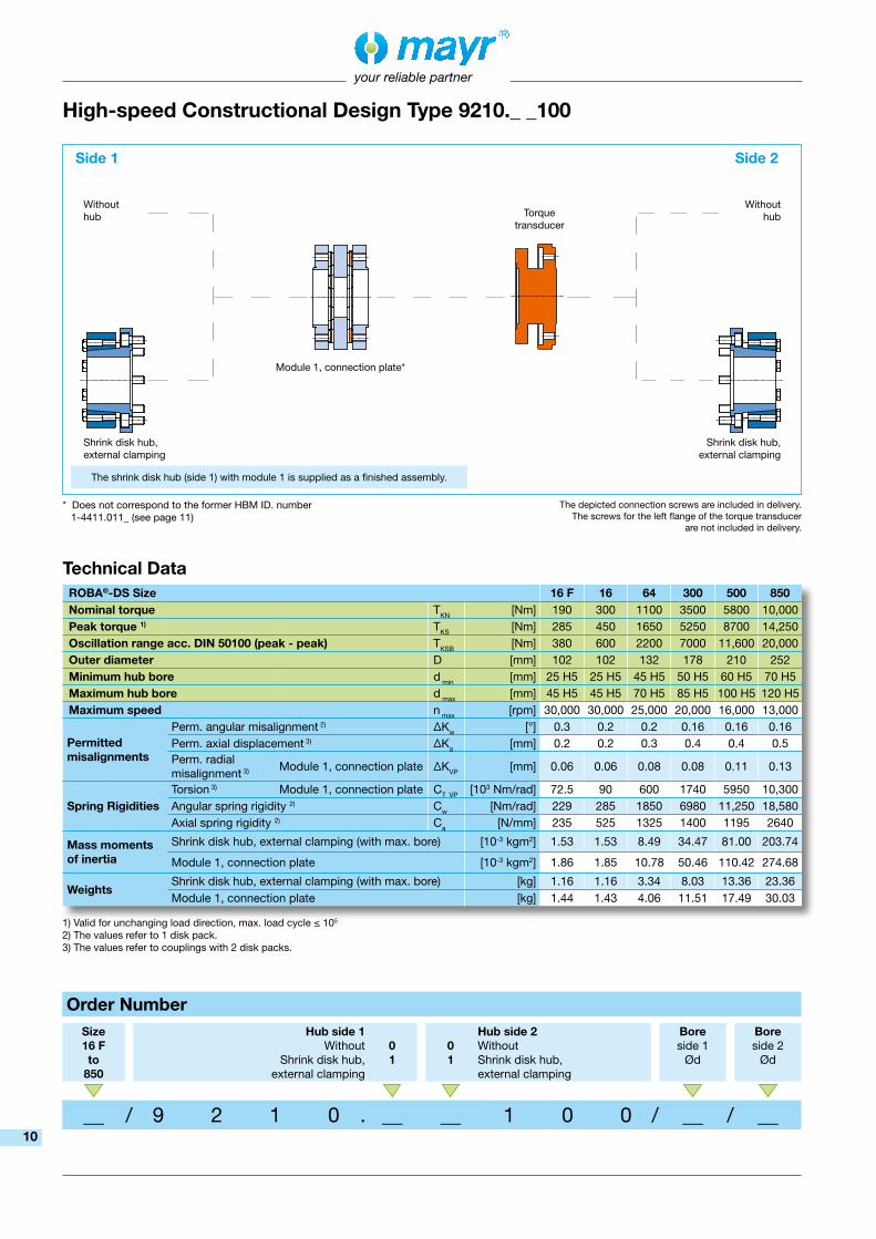
High-speed Constructional Design Type 9210._ _100
Shrink disk hub, external clamping
Module 1, connection plate*
Shrink disk hub, external clamping
Order NumberSize16 Fto
850
Hub side 1Without
Shrink disk hub, external clamping
01
01
Hub side 2WithoutShrink disk hub, external clamping
Boreside 1
Ød
Boreside 2
Ød
__ / 9 2 1 0 . __ __ 1 0 0 / __ / __
Without hub
Without hubTorque
transducer
Side 1 Side 2
Technical Data ROBA®-DS Size 16 F 16 64 300 500 850Nominal torque TKN [Nm] 190 300 1100 3500 5800 10,000Peak torque 1) TKS [Nm] 285 450 1650 5250 8700 14,250Oscillation range acc. DIN 50100 (peak - peak) TKSB [Nm] 380 600 2200 7000 11,600 20,000Outer diameter D [mm] 102 102 132 178 210 252Minimum hub bore d min [mm] 25 H5 25 H5 45 H5 50 H5 60 H5 70 H5Maximum hub bore d max [mm] 45 H5 45 H5 70 H5 85 H5 100 H5 120 H5Maximum speed n max [rpm] 30,000 30,000 25,000 20,000 16,000 13,000
Permittedmisalignments
Perm. angular misalignment 2) ∆Kw [°] 0.3 0.2 0.2 0.16 0.16 0.16Perm. axial displacement 3) ∆Ka [mm] 0.2 0.2 0.3 0.4 0.4 0.5Perm. radial misalignment 3)
Module 1, connection plate ∆KVP [mm] 0.06 0.06 0.08 0.08 0.11 0.13
Spring RigiditiesTorsion 3) Module 1, connection plate CT VP [103 Nm/rad] 72.5 90 600 1740 5950 10,300Angular spring rigidity 2) Cw [Nm/rad] 229 285 1850 6980 11,250 18,580Axial spring rigidity 2) Ca [N/mm] 235 525 1325 1400 1195 2640
Mass moments of inertia
Shrink disk hub, external clamping (with max. bore) [10-3 kgm2] 1.53 1.53 8.49 34.47 81.00 203.74
Module 1, connection plate [10-3 kgm2] 1.86 1.85 10.78 50.46 110.42 274.68
WeightsShrink disk hub, external clamping (with max. bore) [kg] 1.16 1.16 3.34 8.03 13.36 23.36Module 1, connection plate [kg] 1.44 1.43 4.06 11.51 17.49 30.03
1) Valid for unchanging load direction, max. load cycle ≤ 105
2) The values refer to 1 disk pack.3) The values refer to couplings with 2 disk packs.
* Does not correspond to the former HBM ID. number 1-4411.011_ (see page 11)
The shrink disk hub (side 1) with module 1 is supplied as a finished assembly.
The depicted connection screws are included in delivery.The screws for the left flange of the torque transducer
are not included in delivery.
10

l1
ØD
1
ØT K
ØZ
1
k
b1
f1
Ød
Ød 2
a
U1U2 U2
L2
ØD
ØT K
ØZ
A
f S f
a
your reliable partner
Shrink disk hub, external clamping
Module 1, connection plate *
Size 16 F 16 64 300 500 850
a 6x M8 8x M10 8x M12 8x M14 8x M16
b1 9.6 14.6 21 20 26.6
d2 77 120 164 198 234
f1 3.5 4 5 4 4
k 3.5 5.3 5.3 6.4 7.5
l1 38 58 70 80 98
D1 102 132 167 193 240
TK 84 101.5 130 155.5 196
Zi 57 H5 75 H5 90 H5 110 H5 140 H5
Size 16 F 16 64 300 500 850
a 6x M8 6x M8 8x M10 8x M12 8x M14 8x M16
f 3 3 3 2.5 2.5 3
D 99 99 132 178 210 252
L2 46.2 41.2 63.4 88 100 116
S 7.1 4.6 6.8 11.2 12 14
TK 84 84 101.5 130 155.5 196
U2 10 10 16 22 25.5 29
U1 26.2 21.2 31.4 44 49 58
ZA 57 g5 57 g5 75 g5 90 g5 110 g5 140 g5
mayr® article no. 8200430 8198450 8195550 8200508 8200434
HBM article no. 1-4411.0110 1-4411.0111 1-4411.0112 1-4411.0113 1-4411.0114
ROBA®-DS Size 16 64 300 500 850
Dimensions on request
These designs can still be obtained for replacement directly from mayr® power transmission.
* Does not correspond to the former HBM ID. number 1-4411.011_ (see page below)
Module according to Former HBM ID. Number 1-4411.011_
Type 9210.10000
Type 9210._ _100 *
Dimensions of the Components
11

your reliable partner
ROBA®-DS for High Torques – Sizes 2200 to 11000
On the ROBA®-DS with conical connection, the disk pack is connected via positive-locking with the hubs, the flanges or the sleeves. Externally conical bolts are pulled into conical bores in the attachment parts and the collar bushings of the disk packs by tensioning screws. The conical shape produces forces which widen the collar bushings and the attachment parts radially elastically, thus guaranteeing a backlash-free connection of the disk pack.
For this backlash-free, positive locking connection, far lower screw tightening torques are required in comparison to standard frictionally locking connections. This makes installation substantially easier.
The disk packs and the sleeves can be installed and de-installed radially without having to move the respective aggregates.
� Low screw tightening torques
� Can be installed / de-installed radially
� Easy and quick installation / de-installation
� No hydraulic installation tools required; can be installed with a torque wrench
� Backlash-free torque transmission
� FEM-optimized disk shape
� High torsional rigidity
� High performance density
� Compensation of axial, angular and radial misalignments
� Wear and maintenance-free
� High flexibility through customer-specific hubs and sleeves
ROBA®-DS with conical connection
When installed, the cone bolt is pulled by the tensioning screw into the conical core.
For de-installation of the disk pack, the tensioning screw is screwed out and together with the press cover screwed into the cone bolt on the opposite side. This loosens the cone bolt and it can be pulled back axially. In this way, the disk pack and the sleeve can be de-installed radially.
Sleeve Disk pack
Conical connection in installed condition De-installation
Hub
Cone bolt
Press cover
Tensioning screw
Easy installation and de-installation
12

your reliable partner
ROBA®-DS for High Torques – Measurement Flange Variants
Direct installation of the measurement flange onto the input or output. This produces a very rigid connection.
The measurement flange is positioned between the two disk packs. This way, the measurement flange can be de-installed radially with the sleeve, for example for calibration, without de-installing the hubs. Backlash-free shaft-hub connection via shrink disk hub or hub with external shrink disks ensures maximum precision.
Diverse connection variants can be implemented through externally bolted flange hubs or internally bolted measurement flanges, e.g. combinations of very different shaft diameters / measurement flange sizes.
Fig. 4
Fig. 3
Fig. 2
Fig. 1a
Fig. 1b
Figs. 1a and 1b: Classic structure for applications with measurement flange. The screw connection on the measurement flange is accessible from the outside. The measurement flange is tied rigidly to the hub.
13

∆Ka
∆K
r
2 ×
∆K
w
∆K
w
your reliable partner
Angular misalignm
ent ∆Kw [%
]
Axial displacement ∆Ka [%]
Rad
ial m
isal
ignm
ent
∆K
r [%
]
Technical Explanations
Coupling alignmentExact coupling alignment reduces the reaction forces and therefore increases the lifetime of the coupling and the shaft bearing. This will ensure that the measurement line/drive line runs far more smoothly.
Permitted misalignment of the shaft endsShould several types of misalignment occur simultaneously, they will influence each other, i.e. the permitted misalignment values are dependent on one another. The sum of the actual misalignment as a percentage of the maximum value must not exceed 100%, see example.
Valid standards Coupling characteristic values according to DIN 740, Part 2, Section 2.1.Stress dimensions according to DIN 740, Part 2, Sections 2.2 and 3 (dimensioning of the coupling for special applications).Coupling dynamically balanced according to ISO 1940.
General guidelines for installationThe disk packs of the coupling must not be overexpanded beyond the stated permitted flexibilities!
Installation positionThe ROBA-DS® shaft coupling with the torque measurement flange can be operated in any installation position (horizontal or vertical). In case of vertical operation, please make sure that the permitted axial force is not exceeded by the test stand-side masses.
Example (see Table on page 10 and Fig. 5):
ROBA®-DS Size 300, Type 9210.11100
= > An axial displacement of ∆Ka = 0.16 mm equates to 40 % of the permitted maximum value ∆Ka = 0.4 mm.
= > A simultaneously occurring angular misalignment in the disk pack of ∆Kw = 0.048° equates to 30 % of the permitted maximum value ∆Kw = 0.16°.
= > From this, a still-permitted radial misalignment of ∆Kr = 30 % results from the maximum value ∆Kr = 0.08 mm, i.e. maximum 0.024 mm is permitted.
Fig. 5
14

your reliable partner
❑ ROBA-stop® standard Multifunctional all-round safety brakes
❑ ROBA-stop®-M motor brakes Robust, cost-effective motor brakes
❑ ROBA-stop®-S Water-proof, robust monoblock brakes
❑ ROBA®-duplostop®/ROBA®-twinstop®/ROBA-stop®-silenzio®
Doubly safe elevator brakes ❑ ROBA®-diskstop®
Compact, very quiet disk brakes ❑ ROBA®-topstop®
Brake systems for gravity loaded axes ❑ ROBA®-linearstop
Backlash-free brake systems for linear motor axes ❑ ROBA®-guidestop
Backlash-free holding brake for profiled rail guides ❑ ROBATIC®/ROBA®-quick/ROBA®-takt
Electromagnetic clutches and brakes, clutch brake units
❑ smartflex®/primeflex®
Perfect precision couplings for servo and stepping motors ❑ ROBA®-ES
Backlash-free and damping for vibration-sensitive drives ❑ ROBA®-DS/ROBA®-D
Backlash-free, torsionally rigid all-steel couplings ❑ ROBA®-DSM
Cost-effective torque-measuring couplings
❑ EAS®-Compact®/EAS®-NC/EAS®-smartic®
Positive locking and completely backlash-free torque limiting clutches ❑ EAS®-reverse
Reversing re-engaging torque limiting clutch ❑ EAS®-element clutch/EAS®-elements
Load-disconnecting protection against high torques ❑ EAS®-axial
Exact limitation of tensile and compressive forces ❑ EAS®-Sp/EAS®-Sm/EAS®-Zr
Load-disconnecting torque limiting clutches with switching function ❑ ROBA®-slip hubs
Load-holding, frictionally locked torque limiting clutches ❑ ROBA®-contitorque
Magnetic continuous slip clutches ❑ EAS®-HSC/EAS®-HSE
High-speed torque limiters for high-speed applications
❑ tendo®-PM Permanent magnet-excited DC motors
Torque Limiters/Overload Clutches
Shaft Couplings
Electromagnetic Brakes/Clutches
DC Drives
Product Summary
15

04/1
0/20
18 G
C/S
C
your reliable partner
Headquarters
Chr. Mayr GmbH + Co. KGEichenstraße 1, D-87665 MauerstettenTel.: +49 83 41/8 04-0, Fax: +49 83 41/80 44 21www.mayr.com, E-Mail: [email protected]
Representatives
More representatives:
Belgium, Brazil, Canada, Colombia, Croatia, Denmark, Finland, Greece, Hongkong, Hungary, Indonesia, Israel, Luxembourg, Malaysia, Mexico,New Zealand, Norway, Philippines, Portugal, Romania, Russia, Slovakia, Slovenia, South Africa, Spain, Sweden, ThailandYou can find the complete address for the representative responsible for your area under www.mayr.com in the internet.
Branch office
Service Germany/Austria
Baden-WürttembergEsslinger Straße 770771 Leinfelden-EchterdingenTel.: 07 11/45 96 01 0Fax: 07 11/45 96 01 10
BavariaIndustriestraße 5182194 GröbenzellTel.: 0 81 42/50 19 80-7
ChemnitzBornaer Straße 20509114 ChemnitzTel.: 03 71/4 74 18 96Fax: 03 71/4 74 18 95
FrankenUnterer Markt 991217 HersbruckTel.: 0 91 51/81 48 64Fax: 0 91 51/81 62 45
KamenHerbert-Wehner-Straße 259174 KamenTel.: 0 23 07/24 26 79Fax: 0 23 07/24 26 74
NorthSchiefer Brink 832699 ExtertalTel.: 0 57 54/9 20 77Fax: 0 57 54/9 20 78
ChinaMayr ZhangjiagangPower Transmission Co., Ltd. Fuxin Road No.7, Yangshe Town215637 ZhangjiagangTel.: 05 12/58 91-75 67Fax: 05 12/58 91-75 [email protected]
Great BritainMayr Transmissions Ltd.Valley Road, Business ParkKeighley, BD21 4LZWest YorkshireTel.: 0 15 35/66 39 00Fax: 0 15 35/66 32 [email protected]
FranceMayr France S.A.S.Z.A.L. du MinopoleRue Nungesser et Coli62160 Bully-Les-MinesTel.: 03.21.72.91.91Fax: [email protected]
ItalyMayr Italia S.r.l.Viale Veneto, 335020 Saonara (PD)Tel.: 0498/79 10 20Fax: 0498/79 10 [email protected]
SingaporeMayr Transmission (S) PTE Ltd.No. 8 Boon Lay Way Unit 03-06, TradeHub 21Singapore 609964 Tel.: 00 65/65 60 12 30Fax: 00 65/65 60 10 [email protected]
SwitzerlandMayr Kupplungen AGTobeläckerstraße 118212 Neuhausen am RheinfallTel.: 0 52/6 74 08 70Fax: 0 52/6 74 08 [email protected]
USAMayr Corporation10 Industrial AvenueMahwahNJ 07430Tel.: 2 01/4 45-72 10Fax: 2 01/4 45-80 [email protected]
AustraliaDrive Systems Pty Ltd.8/32 Melverton DriveHallam, Victoria 3803AustralienTel.: 0 3/97 96 48 [email protected]
IndiaNational EngineeringCompany (NENCO)J-225, M.I.D.C. Bhosari Pune 411026Tel.: 0 20/27 13 00 29Fax: 0 20/27 13 02 [email protected]
JapanMATSUI Corporation2-4-7 AzabudaiMinato-kuTokyo 106-8641Tel.: 03/35 86-41 41Fax: 03/32 24 24 [email protected]
NetherlandsGroneman BV Amarilstraat 117554 TV Hengelo OVTel.: 074/2 55 11 40Fax: 074/2 55 11 [email protected]
PolandWamex Sp. z o.o. ul. Pozaryskiego, 2804-703 WarszawaTel.: 0 22/6 15 90 80Fax: 0 22/8 15 61 [email protected]
South KoreaMayr Korea Co. Ltd.15, Yeondeok-ro 9beon-gilSeongsan-gu51571 Changwon-siGyeongsangnam-do. KoreaTel.: 0 55/2 62-40 24Fax: 0 55/2 62-40 [email protected]
TaiwanGerman Tech Auto Co., Ltd.No. 28, Fenggong Zhong Road, Shengang Dist.,Taichung City 429, Taiwan R.O.C.Tel.: 04/25 15 05 66Fax: 04/25 15 24 [email protected]
Czech RepublicBMC - TECH s.r.o.Hviezdoslavova 29 b62700 BrnoTel.: 05/45 22 60 47Fax: 05/45 22 60 [email protected]
Rhine-MainKreuzgrundweg 3a36100 PetersbergTel.: 06 61/96 21 02 15
AustriaPummerinplatz 1, TIZ I, A274490 St. Florian, AustriaTel.: 0 72 24/2 20 81-12Fax: 0 72 24/2 20 81 89
TurkeyRepresentative Office TurkeyKucukbakkalkoy Mah.Brandium Residence R2 Blok D:25434750 Atasehir - Istanbul, TurkeyTel.: 02 16/2 32 20 44 Fax: 02 16/5 04 41 [email protected]
Top Related