


Languages
Pages
Legal


Your Presenters: Scott Bayon / Director of Sales Anguil Environmental Systems Brian Kunkle / Director of Systems Sales Verantis Environmental Solutions Group.

Quiz Status and Certificate

PDH Overview
• Today’s Webinar Value = 1 PDH/CH. • Must Be Present for at least 50 Minutes. • Must Complete and Pass Test (8 out of 10). • Available for 32 states. • Keep a Record Log. • Verantis will Keep Records for Six Years. • Contact Mary Rusnak @ Verantis with
Questions.

Agenda
Air Pollution Abatement Technology Overview Emission & Application Overview Thermal & Catalytic Oxidizers Wet Scrubbers Question & Answer Quiz for PDH Credits (Optional)
Topics covered throughout:
● Applicable Industries ● Unique Airstreams ● Airflow & Concentration Ranges ● Removal Efficiencies ● Equipment Options & Selection ● Operating Costs

Thermal & Catalytic Oxidizer Types Thermal
Recuperative Oxidizer
Emission Concentrator
Regenerative Thermal Oxidizer
(RTO)
Direct-Fired Thermal Oxidizer
(DFTO)
Catalytic Recuperative
Oxidizer
Enclosed Flare - Vapor Combustor

What is Oxidation?
Target Pollutants:
• VOCs (Volatile Organic Compounds)
• HAPs (Hazardous Air Pollutants)
• NOx (Nitrogen Oxides)
Plus Odors!
CnH2m + (n + m/2) O2 ⇒ n CO2 + mH2O + heat
Three “T”s: Time, Temperature & Turbulence

Regenerative Thermal Oxidizer (RTO)
Broad Range of Applications: Coating, Printing, Laminating, Painting, Finishing
• Air Flow Range:
1,000-80,000scfm / Single Unit
>80,000 / Multiple Units
• Concentration Range:
0-25% LEL (Lower Explosive Limit)
• Energy-Efficient Operation:
95-97%+ TER (Thermal Energy Recovery)
• High Destruction Rate Efficiency (DRE):
Two Chamber RTOs: 99%+
Multi-Chamber RTOs: 99.7%+

RTO Mode of Operation
RTOs maximize heat recovery from combustion to pre-heat incoming solvent laden air and reduce fuel consumption.
Self-sustains at low
concentrations!

RTO Ceramic Media Options
Random Packing · Typically 1” or 1½” · ½” – 3” Available
Extruded Honeycomb Monolith · Variety of cell sizes and wall widths · Typical block size: 150 x 150 x 300
Multi-Layered Media · Style and Size Options
Advances in Ceramic Media Now Allow for 97% Thermal Energy
Recovery!

Additional RTO Options • Hot Side Bypass Allows the system to handle high loading. • Bake-Out Feature Recommended for streams with particulate and condensables. • Supplemental Fuel Injection (SFI) Reduces combustion air needs and NOX emissions. • Puff / Purge Chamber Used for visible emissions, odors or higher DRE • Induced Fan Arrangement Used on corrosive applications or airstreams with particulate.
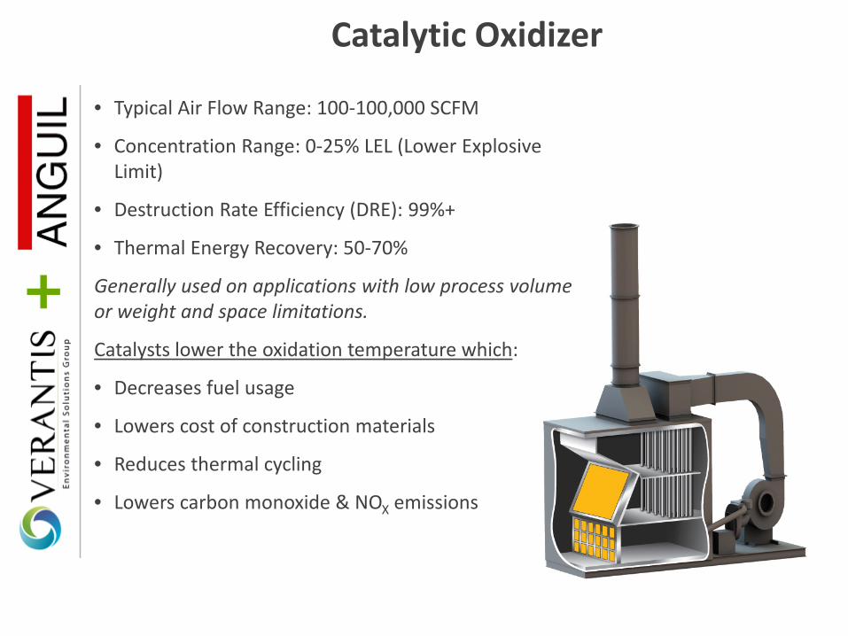
Catalytic Oxidizer
• Typical Air Flow Range: 100-100,000 SCFM
• Concentration Range: 0-25% LEL (Lower Explosive Limit)
• Destruction Rate Efficiency (DRE): 99%+
• Thermal Energy Recovery: 50-70%
Generally used on applications with low process volume or weight and space limitations.
Catalysts lower the oxidation temperature which:
• Decreases fuel usage
• Lowers cost of construction materials
• Reduces thermal cycling
• Lowers carbon monoxide & NOX emissions

Thermal Recuperative Oxidizer
• Typical Air Flow Range: 100-30,000scfm
• Concentration Range: 0-50% LEL (Lower Explosive Limit)
• Destruction Rate Efficiency (DRE): 99%+
• Thermal Energy Recovery: 50-70%
Generally used on applications with:
• High emission concentrations
• Capital cost limitations
• Process heating needs
• Silica dusts in the airstream

Direct Fired Thermal Oxidizer (DFTO)
• Typical Air Flow Range: 100-100,000 SCFM
• Concentration Range: 15-25% LEL (Lower Explosive Limit)
• Destruction Rate Efficiency (DRE): 99.5%+
• Thermal Energy Recovery (TER): None without secondary heat recovery
Generally used on applications with:
• Inert gases
• Low process volume
• Varying process conditions
• High destruction efficiency requirements
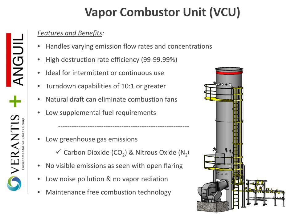
Features and Benefits:
• Handles varying emission flow rates and concentrations
• High destruction rate efficiency (99-99.99%)
• Ideal for intermittent or continuous use
• Turndown capabilities of 10:1 or greater
• Natural draft can eliminate combustion fans
• Low supplemental fuel requirements
----------------------------------------------------------------
• Low greenhouse gas emissions
Carbon Dioxide (CO2) & Nitrous Oxide (N2O)
• No visible emissions as seen with open flaring
• Low noise pollution & no vapor radiation
• Maintenance free combustion technology
Vapor Combustor Unit (VCU)

Emission Concentrator
Converts high process air volumes with low VOC concentrations into a low volume, higher concentration stream.
Technology Applicability: • Inlet Temperature < 100ºF (40ºC) • VOC Concentrations < 500 ppm.
Higher concentrations reduce concentration factor making this technology uneconomical.
• Relative Humidity < 90% • Low boiling point VOCs

How Do Concentrators Work?
Large Flow / Low Concentration
Airstream
Small Flow / High Concentration
Airstream

Operating Cost Comparison
Design Basis:
• 10,000 SCFM process exhaust flow
• 100°F process exhaust temperature
• 15 lbs./hr. styrene emissions
• $5/MM BTU gas cost
• $0.07/KWH electrical cost

Operating Cost Reduction Strategies
1. Know the estimated and actual oxidizer operating costs for gas usage and electrical consumption.
2. Pay attention to percentages.
• A 1% drop in thermal efficiency for a standard RTO equates to a 20% increase in natural gas consumption.
3. Monitor emission loading. Have process conditions changed since the oxidizer was installed?
4. Determine what type of oxidizer System would be specified today. Technologies and components have advanced.

Operating Cost Reduction Strategies
5. Know what state and federal grant money is available. • Database of State Incentives for Renewables & Efficiency:
www.dsireusa.org 6. Consider an emission concentrator for high volume, low concentration process streams; Permanent Total Enclosures (PTE), floor sweeps, washers, spray machines 7. Focus on Combustion Air
• Using ambient air for oxidizer burners is like burning money.
Consider supplying combustion blowers with tempered air from a secondary heat exchanger.
Also ideal for process heating
needs!

Operating Cost Reduction Strategies
8. Improve Primary Heat Recovery
Catalytic & Recuperative: Metal Heat Exchangers
60-80% Efficient
Regenerative Thermal: Ceramic Heat Recovery Media
95-97% Efficient
9. Properly Maintain Existing Systems Did you know some
permits require service documentation?
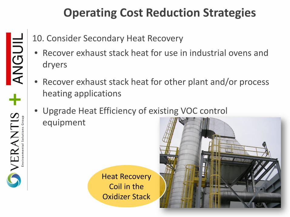
Operating Cost Reduction Strategies
10. Consider Secondary Heat Recovery • Recover exhaust stack heat for use in industrial ovens and
dryers
• Recover exhaust stack heat for other plant and/or process heating applications
• Upgrade Heat Efficiency of existing VOC control equipment
Heat Recovery Coil in the
Oxidizer Stack

Halogenated Hydrocarbons &
Acid Control
Oxidation Reaction Can Produce Acids: Halogenated Hydrocarbon + O2 ⇒ CO2 + H2O + Heat + Inorganic Acid
The presence of halogenated hydrocarbons requires an increase in oxidizer residence time and operating temperature.
Scrubbers Neutralize Acids: HCl + NaOH ⇒ NaCl + H2O

Wet Scrubber

Introduction to Wet Scrubbers
1. Types and classifications of air pollutants.
2. Basic wet scrubber types for different pollutants, with focus on most relevant for thermal oxidation applications.
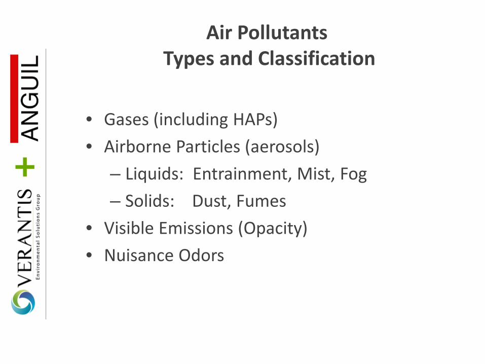
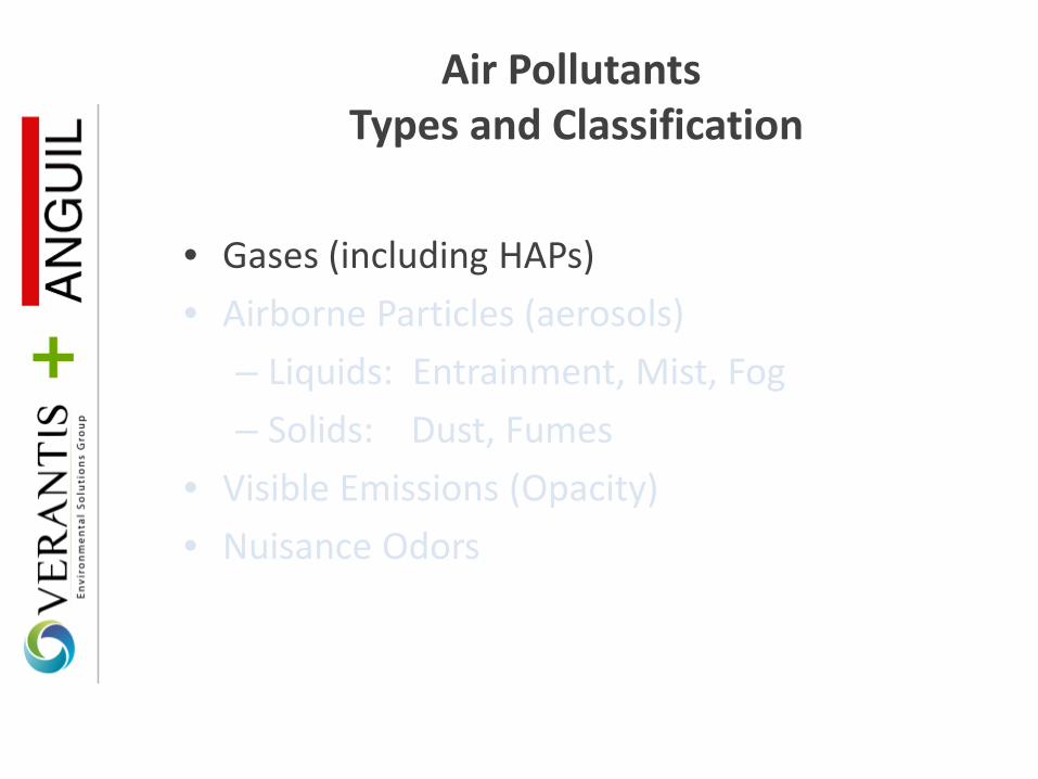
Air Pollutants Types and Classification
• Gases (including HAPs) • Airborne Particles (aerosols)
– Liquids: Entrainment, Mist, Fog – Solids: Dust, Fumes
• Visible Emissions (Opacity) • Nuisance Odors
Air Pollutants Types and Classification
• Gases (including HAPs) • Airborne Particles (aerosols)
– Liquids: Entrainment, Mist, Fog – Solids: Dust, Fumes
• Visible Emissions (Opacity) • Nuisance Odors

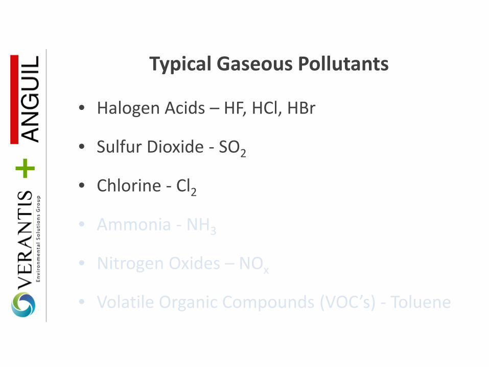
Typical Gaseous Pollutants
• Halogen Acids – HF, HCl, HBr
• Sulfur Dioxide - SO2
• Chlorine - Cl2
• Ammonia - NH3
• Nitrogen Oxides – NOx
• Volatile Organic Compounds (VOC’s) - Toluene
Typical Gaseous Pollutants
• Halogen Acids – HF, HCl, HBr
• Sulfur Dioxide - SO2
• Chlorine - Cl2
• Ammonia - NH3
• Nitrogen Oxides – NOx
• Volatile Organic Compounds (VOC’s) - Toluene

Important Properties of Pollutant Gases for Wet Scrubbing
Solubility - The capability of a substance to dissolve in water. Volatility - The tendency of a substance to vaporize. Reactivity - The capability of a substance to undergo a chemical reaction with another substance.

Gas Scrubbing Chemistry
• HCl + NaOH NaCl + H2O (HBr, HF, etc.)
• SO2 + 2NaOH → Na2SO3 + H2O
• Cl2 + 2NaOH → NaCl + NaOCl + H2O
Note that some low vapor pressure compound like HCl and HF can also be scrubbed into water only if preferred, depending on efficiency requirements and process conditions.

Wet Scrubber Definition
A device that provides intimate contact between a contaminated air stream and a liquid stream to allow for transfer of gases, liquid, or solid contaminants from the air to the liquid. Scrubber types are typically selected based upon achieving the highest contaminant removal while consuming the least amount of energy.

Reasons to use a Wet Scrubber
1. Soluble and/or reactive gases are present. 2. The pollutant cannot be easily removed in dry
form. 3. Liquid droplets or mists are present. 4. Soluble or wettable particulates are present. 5. The pollutant will undergo some subsequent
wet process (such as neutralization). 6. The pollutants are more safely handled wet
than dry (potential explosiveness).
Wet Scrubbing Process
Wet Scrubbing is a two-step process. 1. Capture of the gas and/or particulate in the
liquid.
2. Separation of the scrubbing liquid droplets (entrainment) from the gas stream before leaving the scrubber.

Basic Types Of Wet Scrubbers
• Spray Tower • Countercurrent Packed Tower • Crossflow Packed Bed • Tray Scrubber • Venturi

Basic Types Of Wet Scrubbers
• Spray Tower • Countercurrent Packed Tower • Crossflow Packed Bed • Tray Scrubber • Venturi

Dirty Gas In
Clean Gas Out
Liquid In
Liquid Out
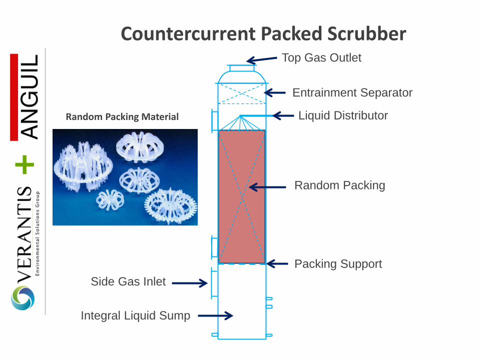
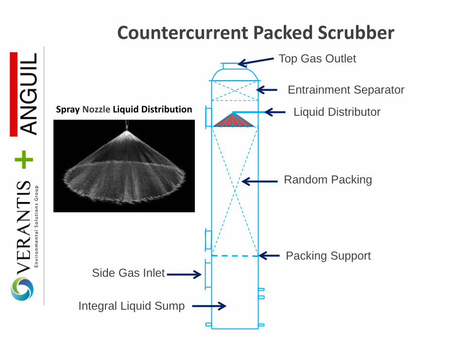
Countercurrent Packed Scrubber

Countercurrent Packed Scrubber
Integral Liquid Sump
Random Packing
Packing Support
Liquid Distributor
Top Gas Outlet
Side Gas Inlet
Entrainment Separator
Countercurrent Packed Scrubber
Integral Liquid Sump
Random Packing
Packing Support
Liquid Distributor
Top Gas Outlet
Side Gas Inlet
Entrainment Separator
Random Packing Material
Countercurrent Packed Scrubber
Integral Liquid Sump
Random Packing
Packing Support
Liquid Distributor
Top Gas Outlet
Side Gas Inlet
Entrainment Separator Spray Nozzle Liquid Distribution

Countercurrent Packed Scrubber
Integral Liquid Sump
Random Packing
Packing Support
Liquid Distributor
Top Gas Outlet
Side Gas Inlet
Entrainment Separator
Chevron Entrainment Separator
Countercurrent Packed Tower
• Vertical configuration with gas flowing upward countercurrent to liquid flow.
• Contains a section of random packing media to provide good mixing and contact of the gas and liquid.
• Used for absorption of soluble and/or reactive gaseous pollutants.
• Also used for impingement of entrained liquids and/or soluble solids (dusts) above 10 micron in size.

Countercurrent Packed Tower Design Considerations
• Commonly employed for gas removal efficiencies in the 90% to 99.99%+ range
• Typical 500-600 ft/min gas velocity range • Packing selection to minimize packed bed height and
pressure drop while maintaining high velocity (and low diameter) equipment – Minimize capital and operating costs
• Gas pressure drop in the typical range of 1 to 6 in-wc, varying based on packing type, entrainment separator type, efficiency requirements
• Typical discharge entrainment separator types include chevron blade assemblies and mesh-pad type separators

Pre-Cooling • A direct contact adiabatic quench system is typically used to efficiently
cool the gas stream to a temperature appropriate for the downstream equipment. A specific approach to the saturation temperature is not required.
• Proper quench design requires good mixing and adequate contact time between the gas and liquid phases to achieve maximum evaporation. As with mass transfer, optimum contacting can be achieved using a number of different methods.
• Quench residence time is defined as the time from the initial contact of gas and liquid and the exit of the quench. This is not necessarily a function of the physical length of the quench.
• If design utilizes circulation of any salt solution, care must be taken to avoid creation of sub-micron salt particulate during evaporation

Quench Arrangements
Quenching Zone
Gas Outlet Q
uenc
hing
Zon
e
Fan Sprays
Horizontal – Low Temp Vertical – High Temp
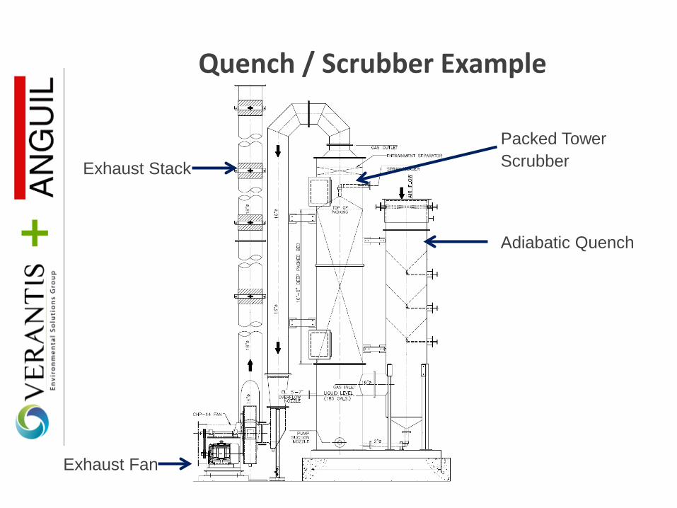
Quench / Scrubber Example
Adiabatic Quench
Packed Tower Scrubber
Exhaust Fan
Exhaust Stack

General Wet Scrubber Selection Guide
Scrubber Type
Gas Absorption
Liquid Aerosols > 10 µm
Liquid Aerosols < 10 µm
Soluble Particulate
> 10 µm
Soluble Particulate
< 10 µm
Insoluble Particulate
> 10 µm
Insoluble Particulate
< 10 µm
Spray Tower G NR NR NR NR NR NR
Packed Tower E E NR E NR NR NR
Crossflow G E NR E NR NR NR
Tray Tower E E NR < 5µm E NR < 5µm E NR < 5µm
Venturi F E E E E E E
E = Excellent
G = Good
F = Fair
NR = Not Recommended
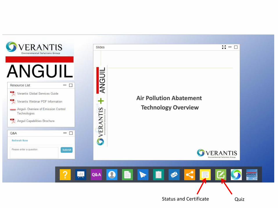
Quiz Status and Certificate

Questions?
Thank You for Attending!
Top Related