


Languages
Pages
Legal


Commercial & Industrial HVACyork air-conditioning products

On the cover...
This shape’s lines are taken from the ultra-modern building shape of the Montreal Biodome. Building Efficiency provides all heating and air conditioning controls to deliver safe and comfortable conditions for the facility’s different inhabitants - ranging from Antarctic temperatures for the penguins to hot and humid conditions for the tropical plants.

A more comfortable,safe and sustainable world
york air-conditioning products

At Johnson Controls, we look at buildings in a way very few others have ever imagined. When we look at a building, we see beyond the bricks and mortar. Beyond the steel and glass. We see a bigger picture. We see the power of the human enterprise.
That’s why we create buildings and environments that help people achieve – and that give buildings, businesses and people every opportunity to reach their full potential.


Solutions for your successEvery building is unique in design and technical requirements.
Our customers always receive customised building solutions to meet their individual needs.
Johnson Controls can handle many challenges with its innovative and flexible solutions. From A to Z, from consulting to planning, installation, maintenance (service, inspection and repair) and modernisation – Johnson Controls supports customers throughout the entire life cycle of a building.
AIR CONDITIONING SOLUTIONS
• Chillers & fan coils• Absorption chillers• Cooling towers• Dry coolers• Air Handling Units
BUILDING AUTOMATION
• Monitoring, control and optimisation• Standardised communication protocols
SECURITY SOLUTIONS
• Identity management• Facility zoning• Video surveillance systems• Alarm systems
york air-conditioning products
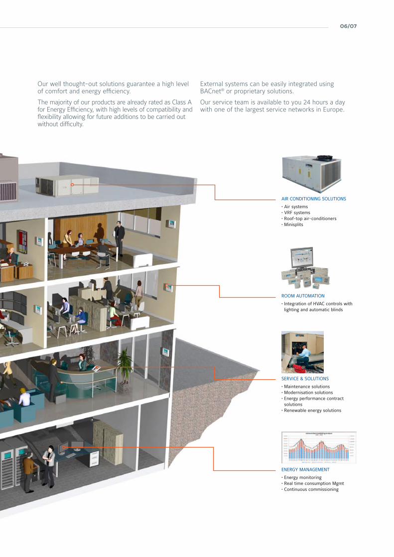
Our well thought-out solutions guarantee a high level of comfort and energy efficiency.
The majority of our products are already rated as Class A for Energy Efficiency, with high levels of compatibility and flexibility allowing for future additions to be carried out without difficulty.
External systems can be easily integrated using BACnet® or proprietary solutions.
Our service team is available to you 24 hours a day with one of the largest service networks in Europe.
AIR CONDITIONING SOLUTIONS
• Air systems• VRF systems• Roof-top air-conditioners• Minisplits
ENERGY MANAGEMENT
• Energy monitoring• Real time consumption Mgmt• Continuous commissioning
ROOM AUTOMATION
• Integration of HVAC controls with lighting and automatic blinds
SERVICE & SOLUTIONS
• Maintenance solutions• Modernisation solutions• Energy performance contract solutions
• Renewable energy solutions
06/07

Catalogue content
york air-conditioning products
Page
ECOFRIO v2 / ECOFRIO v2 Plus Air cooled chiller / heat pump 12
ECOFRIO v2 Air cooled chiller / heat pump 16
YLCD-YLHD Air cooled chiller / heat pump 20
YLAA Air-cooled scroll compressor chiller 24
YLAE-HP Reverse cycle air to water heat pump scroll compressor chiller 26
YLPA Heat pump scroll compressor 28
YVAA Air-cooled VSD screw chiller 30
YMWA / YMRA Water-cooled cooling only, remote condenser and heat pump scroll compressor chiller 32
YCSE Water-cooled or remote air-cooled screw compressor chiller 33
YCWL Water-cooled or remote air-cooled scroll compressor chiller 34
YLCS Water-cooled or remote air-cooled screw compressor chiller 36
YVWA Water-cooled variable speed screw chiller 38
YN Water-cooled screw compressor chiller 40
YR Water-cooled screw compressor chiller 42
YNWS/RS Water-cooled or remote air-cooled screw compressor chiller 44
YNWH Water-cooled screw chiller 45
YMC2 Water-cooled magnetic centrifugal chiller 46
YK Water-cooled centrifugal chiller 48
YIA Single stage hot water or steam powered absorption chiller 50
YPC-ST Two-stage steam fed absorption chiller 52
YPC-F Two-stage direct fired chiller-heater 53
Central Plant Optimization™ 10 54
Chillers & Heat Pumps
08/09
Page
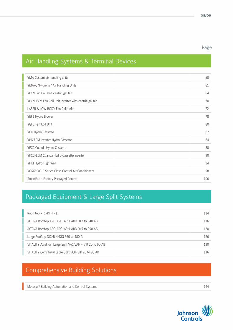
YMA Custom air handling units 60
YMA-C “Hygienic” Air Handling Units 61
YFCN Fan Coil Unit centrifugal fan 64
YFCN-ECM Fan Coil Unit Inverter with centrifugal fan 70
LASER & LOW BODY Fan Coil Units 72
YEFB Hydro Blower 78
YGFC Fan Coil Unit 80
YHK Hydro Cassette 82
YHK ECM Inverter Hydro Cassette 84
YFCC Coanda Hydro Cassette 88
YFCC-ECM Coanda Hydro Cassette Inverter 90
YHM Hydro High Wall 94
YORK® YC-P Series Close Control Air Conditioners 98
SmartPac - Factory Packaged Control 106
Metasys® Building Automation and Control Systems 144
Roomtop RTC-RTH - L 114
ACTIVA Rooftop ARC-ARG-ARH-ARD 017 to 040 AB 116
ACTIVA Rooftop ARC-ARG-ARH-ARD 045 to 090 AB 120
Large Rooftop DIC-BIH-DIG 360 to 480 G 126
VITALITY Axial Fan Large Split VAC/VAH - VIR 20 to 90 AB 130
VITALITY Centrifugal Large Split VCH-VIR 20 to 90 AB 136
Air Handling Systems & Terminal Devices
Comprehensive Building Solutions
Packaged Equipment & Large Split Systems

york air-conditioning products
scroll compressor chillers and heat pumps
screw compressor chillers air-cooled & water-cooled
centrifugal compressor chillers water-cooled
absorption chillers water-cooled
central plant optimisationtm 10
Chillers & Heat Pumps
10/11
york air-conditioning products
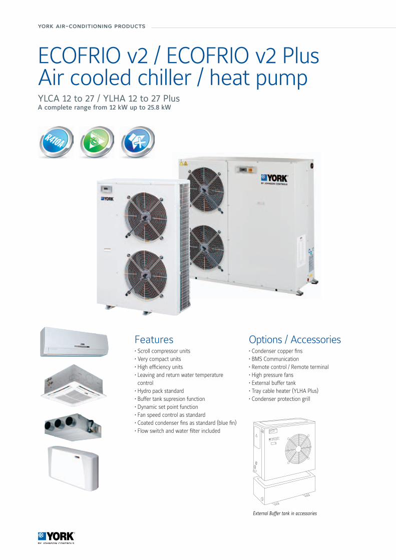
ECOFRIO v2 / ECOFRIO v2 PlusAir cooled chiller / heat pumpYLCA 12 to 27 / YLHA 12 to 27 PlusA complete range from 12 kW up to 25.8 kW
Features• Scroll compressor units• Very compact units • High efficiency units• Leaving and return water temperature control
• Hydro pack standard • Buffer tank supresion function • Dynamic set point function • Fan speed control as standard • Coated condenser fins as standard (blue fin)• Flow switch and water filter included
Options / Accessories• Condenser copper fins • BMS Communication • Remote control / Remote terminal• High pressure fans • External buffer tank• Tray cable heater (YLHA Plus)• Condenser protection grill
External Buffer tank in accessories

Manufacturer reserves the rights to change specifications without prior notice.
Wat
er S
yste
ms
12/13
ECOFRIO v2 / ECOFRIO v2 PlusYLCA 12 to 27 / YLHA 12 to 27 Plus
Compatibility table / CodesYLCA Model 12 TC 15 TC 20 TC 27 TC
Cooling only units (Pack included) S668551282 S668551582 S668552082 S668552782YLHA Plus Model 12 TC 15 TC 20 TC 27 TC
Heat pump units (Pack included) S668651285 S668651585 S668652085 S668652785Use this unit code when a factory fitted option is NOT requiredAccessories (Supplied loose)
Water tank30 Liters S613990300 - S613990300115 Liters - S613991150 - S613991150
Water tank + heater30 L + 4.5 kW (3~) - S613990305 -30 L + 6 kW (3~) - S613990306 -115 L + 10.5 kW (3~) - S613991151
Remote control S613802011Remote terminal S613802231BMS Communication S613802041Anti vibration mounting S613029001 S613029002 S613029001 S613029002Compressor heater S613760322 STANDARD S613760322 STANDARDTray cable heater - S611080788 -
YLCA Model 12 TC 15 TC 20 TC 27 TC
Cooling only units (Pack included) S668000010 S668000012 S668000014 S668000016YLHA Plus Model 12 TC 15 TC 20 TC 27 TC
Heat pump units (Pack included) S6686000239 S6686000242 S6686000243 S6686000244Use this unit code when a factory fitted option is requiredOptions (Factory fitted)
High pressure fans S611991083 S611991085 S611991083 S611991085Condenser protection grill S613995085 S61399086 S61399087 S613995085 S61399086 S61399087LAK -18°C S613112083 STANDARD
Technical features
ModelYLCA G1 YLHA PLUS G1
12 TC 15 TC 20 TC 27 TC 12 TC 15 TC 20 TC 27 TCPerformance Cooling capacity (1) kW 12.4 14.5 19.5 25.6 12 13,8 19.4 25.8
Total Input Power (1) kW 4.2 5.4 6.9 9,1 4.2 5.5 7 8.9EER (1) 2.97 2.52 2.81 2.81 2,88 2,52 2,75 2,9ESEER 3.20 2.91 3.24 3.17 3.08 2.91 3.17 3.25Heating capacity (1) kW - - - - 12,4 16,1 20.9 27.5Total Input Power (1) kW - - - - 4.2 5.2 6.6 8.6COP (1) - - - - 3.0 3,12 3,17 3,2Heating capacity (2) kW - - - - 12.6 16.4 20.5 26.8COP (2) - - - - 3,86 4.0 3,79 3,8Capacity steps % 0 / 100Sound power level dB(A) 73 73 74 78 73 73 74 78Sound pressure level at 10 m dB(A) 43 43 44 48 43 43 44 48
Compressor Type ScrollQuantity 1
Air side heatexchanger
Fans quantity 2Working ambient temp. cool / heat mode (5) (-18°C) -10°C ~ 46°C -18°C ~ 46°C -18°C ~ 46°C / -15°C ~ 20°C
Water side heat exchanger
Type Plate Heat ExchangerUnit water volume Litres 1.5 2 2.8 3.2 1.5 2 2.8 3.2Pump Type Multi stageNominal water flow in cooling l/h 2 065 2 530 3 360 4 405 1 980 2 375 3 335 4 440Available pressure (1) (3) kPa 113 149 129.5 182 116 157.5 124 182Working water leaving temp. cooling/heating mode (4) °C -5°C to 15°C / 30°C to 50°C
Water connections inch 1” 1 1/4” 1” 1 1/4”Dimensions & Weight
Height / Width / Depth mm 1 270 / 905 / 460 1270/1430/502 1270/1876/502 1 270 / 905 / 460 1270/1430/502 1270/1876/502Weight kg 146 160 220 290 150 164 235 330
Electricalfeatures
Voltage / Phases / Frequency V/ph/hz 400-3-50+N+EMaximum Unit current A 11.6 15.8 18.1 23 11.6 12.4 15.5 21
(1) net values at Nominal conditions (2) net values at floor heating conditions (3) with filter (4) below 6°C with glycol (5) -18°C with LAK optionNominal conditions: Cooling capacities for 7°C water leaving temperature ∆t 5°C and 35°C ambient temperature Heating capacities for 45°C water leaving temperature ∆t 5°C and 7°C ambient temperatureFloor heating conditions: Heating capacities for 35°C water leaving temperature ∆t 5°C and 7°C ambient temperature
T Three phases supply C Hydro Pack
york air-conditioning products
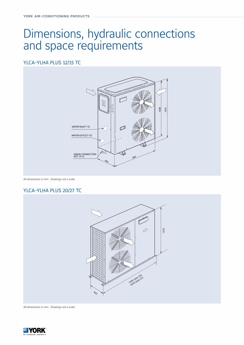
Dimensions, hydraulic connectionsand space requirementsYLCA-YLHA PLUS 12/15 TC
All dimensions in mm. Drawings not a scale.
502
1270
1430 (size 20)
1876 (size 27)
YLCA-YLHA PLUS 20/27 TC
All dimensions in mm. Drawings not a scale.
1270
1238
405905
DRAIN CONNECTIONEXT. Ø 15
WATER INLET 1”G
WATER OUTLET 1”G
Wat
er S
yste
ms
14/15
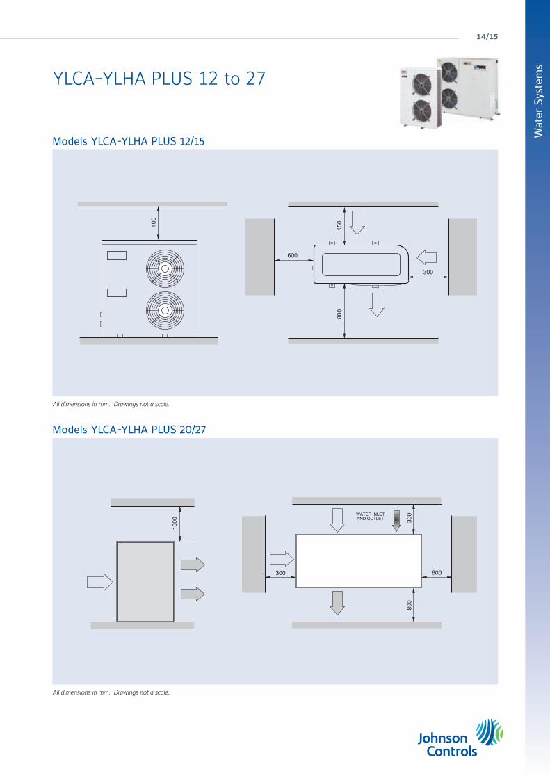
Models YLCA-YLHA PLUS 20/27
All dimensions in mm. Drawings not a scale.
Models YLCA-YLHA PLUS 12/15
All dimensions in mm. Drawings not a scale.
1000
0 0 8
WATERINLET
AND OUTLET
0 0 0 3
0 0 0 1
0 0 8
800
300 600
0 0 3
WATER INLETAND OUTLET
0 0 8
1000
0 0 8
WATERINLET
AND OUTLET
0 0 0 3
0 0 0 1
0 0 8
800
300 600
0 0 3
WATER INLETAND OUTLET
0 0 8
YLCA-YLHA PLUS 12 to 27
york air-conditioning products
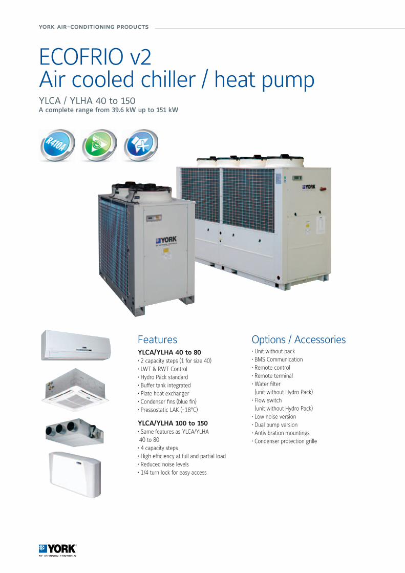
ECOFRIO v2Air cooled chiller / heat pumpYLCA / YLHA 40 to 150A complete range from 39.6 kW up to 151 kW
FeaturesYLCA/YLHA 40 to 80• 2 capacity steps (1 for size 40)• LWT & RWT Control• Hydro Pack standard• Buffer tank integrated• Plate heat exchanger• Condenser fins (blue fin)• Pressostatic LAK (-18°C)
YLCA/YLHA 100 to 150• Same features as YLCA/YLHA 40 to 80• 4 capacity steps• High efficiency at full and partial load• Reduced noise levels• 1/4 turn lock for easy access
Options / Accessories• Unit without pack• BMS Communication• Remote control• Remote terminal• Water filter (unit without Hydro Pack)• Flow switch (unit without Hydro Pack)• Low noise version• Dual pump version• Antivibration mountings• Condenser protection grille

Manufacturer reserves the rights to change specifications without prior notice.
Wat
er S
yste
ms
16/17
Technical features
ModelYLCA / YLHA
40 T-TP 50 T-TP 60 T-TP 80 T-TP 100 T-TP 120 T-TP 150 T-TP
Performance
Cooling capacity c/o units (1) kW 39.6 52.1 60.5 77.6 98 119 151Total Input Power (1) (3) kW 13.26 17.96 19.6 26.6 33.8 40 53.6EER (1) 2.99 2.9 3.09 2.92 2.9 2.98 2.82ESEER (1) 3.31 3.24 3.44 3.26 3.56 3.80 3.60Cooling capacity h/p units (1) kW 37.8 52 60.5 72.2 96 114 145Heating capacity h/p units (1) kW 38.6 52.5 59.6 74.7 104 119.6 150Total Input Power cool/heat mode (1) kW 13.3 / 12.6 17.3 / 17.9 19.6 / 19.8 26 / 26.4 35.5 / 37.1 43.2 / 39.6 50.6 / 53.5EER / COP (1) 2.84/3.14 3/2.93 3.09/3.01 2.78/2.83 2.7 / 2.8 2.64/3.02 2.87/2.8ESEER (1) 3.30 3.24 3.44 3.26 3.65 3.71 3.7Capacity steps % 0 / 100 0-50-100 0-25-50-75-100Sound power level STD / LN dB(A) 81 / 76 83 / 78 85 / 80 86 / 82 86 / 82 86 / 82 87 / 83Sound press. level 10 m STD / LN dB(A) 54 / 48 56 / 50 57 / 51 60 / 54 57 / 54 58 / 54 59 / 55
CompressorType ScrollQuantity 1 2 4
Air sideheat exchanger
Fans quantity 2 3 4Working ambient temp. cool. / heat. mode (4) -18°C ~ 46°C / -10°C ~ 20°C
Waterside heatexchanger
Type Single Plate Heat Exchanger Dual Plate Heat ExchangerUnit water volume (2) Litres 131 188 194 285 193 195 214Pump Type Multistage horizontal pumpsNominal water flow l/h 6 820 8 960 10 400 13 350 17 600 20 470 25 970Available pressure (1) (2) kPa 105 108 158 123 187 202 186Pressure drop (1) (3) kPa 75 40 51 61 54 32 27.5Working range water leaving temperature cooling / heating (5) -5°C ~ 15°C / 30°C ~ 50°C
Water connections (2) inch 1 1/4” 2” 2 1/2”
Dimensions& Weight
Height / Width / Depth mm 1573/1500/822 1600 / 1011 / 2104 1600/1118/2944 2190 / 1101 / 3416 2263/1101/3770Weight without pack / pack c/o kg 340 / 380 524 / 580 555 / 611 715 / 785 1 124 / 1 220 1 190 / 1 286 1 415 / 1 503Weight without pack / pack h/p kg 337 / 397 537 / 593 568 / 624 735 / 805 1 154 / 1 250 1 220 / 1 316 1 445 / 1 703
Electricalfeatures
Voltage / Phases / Frequency V/ph/hz 400 / 3 / 50+N+EMaximum Unit current A 33 46.2 49.2 70.5 80 108 120
YLCA: Cooling only units models. YLHA: Air to water heat pump models.(1) net values at Eurovent nominal conditions (2) version P with hydro kit with filter (3) version without hydro kit (4) -18°C with LAK option (5) below 6°C with glycolNominal conditions: Cooling capacities in kW given for 7°C water leaving temperature ∆t 5°C and 35°C ambient temperature Heating capacities in kW given for 45°C water leaving temperature and 7°C ambient temperature
T Three phases supply P Hydro Pack H Heat pump
Compatibility table / CodesModel 40 TP 50 TP 60 TP 80 TP 100 TP 120 TP 150 TPYLCA Cooling only unit (Pack included) S668554084 S668525182 S668526182 S668528182 S668521182 S668551156 S668551507YLHA Heat pump unit (Pack included) S668654084 S668625182 S668626182 S668628182 S668621182 S668651156 S668651506
Model 40 T 50 T 60 T 80 T 100 T 120 T 150 TYLCA Cooling only unit (without Pack) S668554080 S668525180 S668526180 S668528180 S668521180 S668551154 S668551503YLHA Heat pump unit (without Pack) S668654080 S668625180 S668626180 S668628180 S668621180 S668651154 S668651504Use this unit code when a factory fitted option is NOT requiredAccessories (Supplied loose)
AVM mounting S613029002 S613026080 S613028180 S613021580Mechanical flow switch S611992021Water Filter * S611300150 S611300170 S611300190Remote control S613802011Remote terminal S613802231 -Cable for remote connection of the terminal - S613802241B.M.S. Communication S613802041 S613802051
Model 40 TP 50 TP 60 TP 80 TP 100 TP 120 TP 150 TPYLCA Cooling only unit (Pack included) S668000226 S668000247 S668000251 S668000255 S668000259 S668000107 S668000111YLHA Heat pump unit (Pack included) S668000228 S668000248 S668000252 S668000256 S668000260 S668000131 S668000135
Model 40 T 50 T 60 T 80 T 100 T 120 T 150 TYLCA Cooling only unit (without Pack) S668000038 S668000245 S668000249 S668000253 S668000257 S668000105 S668000109YLHA Heat pump unit (without Pack) S668000039 S668000246 S668000250 S668000254 S668000258 S668000129 S668000133Use this unit code when a factory fitted option is requiredOptions (Factory fitted)
Low Noise version S603990550 S613990650 S613990850 S613991050 S613991285 S613991584Softstart S606744692 S606744693 S606744694Dual pumps - S613990540 S613990640 S613990840 S613991040 S613991286 S613991585Condenser protection grille S613995090 S613995091 S613995092 S613995093 S613995094
* included with unit version “P” only for unit without pack. Filter size: 2” for YLCA 40-50-60-80 and 2 1/2” for YLHA 100-120-150.
ECOFRIO v2YLCA / YLHA 40 to 150
york air-conditioning products
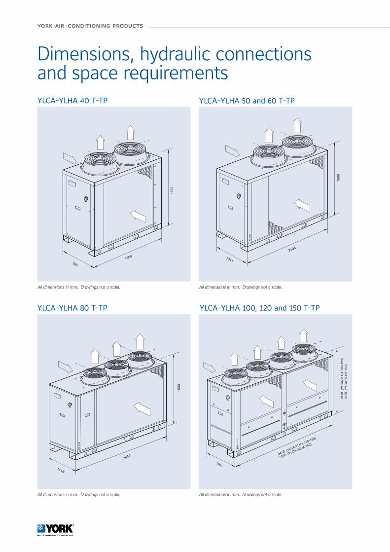
YLCA-YLHA 50 and 60 T-TP
YLCA-YLHA 100, 120 and 150 T-TP
All dimensions in mm. Drawings not a scale.
YLCA-YLHA 40 T-TP
All dimensions in mm. Drawings not a scale. All dimensions in mm. Drawings not a scale.
1500
3751
822
YLCA-YLHA 80 T-TP
All dimensions in mm. Drawings not a scale.
2944
0061
1118
2104
0061
1011
3416 (YLCA-YLHA 100-120)
3770 (YLCA-YLHA 150)
2190
(YL
CA-
YLH
A 10
0-12
0)22
63 (
YLC
A-YL
HA
150)
1101
Dimensions, hydraulic connectionsand space requirements

Wat
er S
yste
ms
18/19
YLCA-YLHA 100, 120 and 150 T-TP
All dimensions in mm. Drawings not a scale.
YLCA-YLHA 50, 60 and 80 T-TP
All dimensions in mm. Drawings not a scale.
3000
1000 1500
1000
1000
INLET /OUTLETWATER
3000
1000 1500
1000
1000
INLET /OUTLETWATER
WATERINLET /OUTLET
1000 1500
1500
1500
3000
WATERINLET /OUTLET
1000 1500
1500
1500
3000
YLCA-YLHA 40 T-TP
All dimensions in mm. Drawings not a scale.
1000
0 0 8
WATERINLET
AND OUTLET
0 0 0 3
0 0 0 1
0 0 8
800
300 600
0 0 3
WATER INLETAND OUTLET
0 0 8
1000
0 0 8 WATERINLET
AND OUTLET
0 0 0 3
0 0 0 1
0 0 8
800
300 600
0 0 3
WATER INLETAND OUTLET
0 0 8
YLCA / YLHA 40 to 150
york air-conditioning products
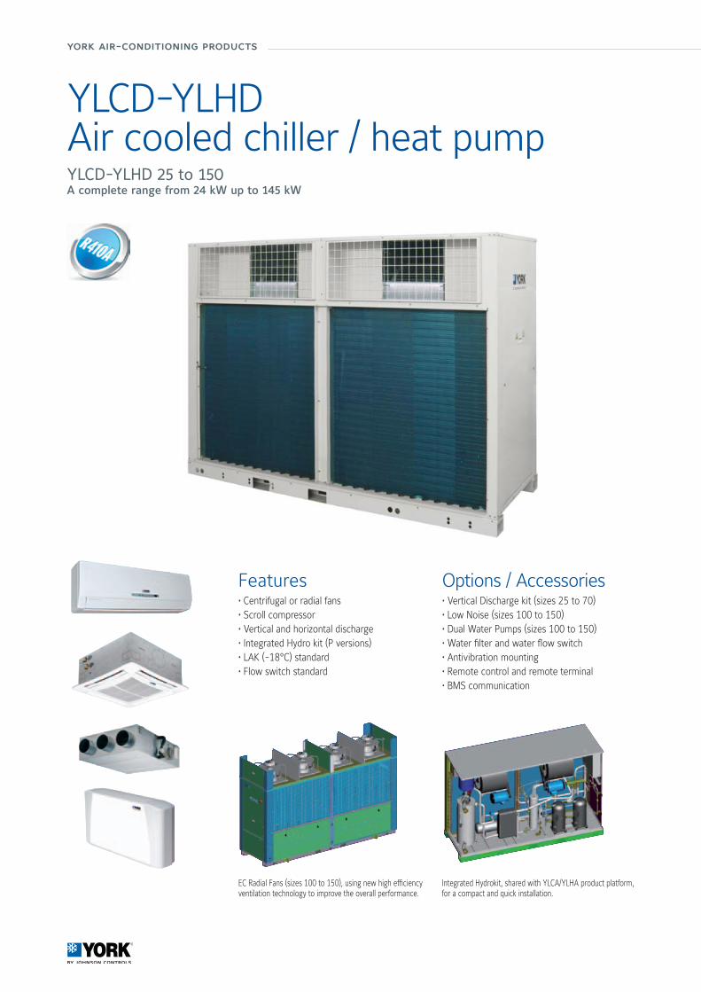
YLCD-YLHDAir cooled chiller / heat pumpYLCD-YLHD 25 to 150A complete range from 24 kW up to 145 kW
Features• Centrifugal or radial fans• Scroll compressor• Vertical and horizontal discharge• Integrated Hydro kit (P versions)• LAK (-18°C) standard• Flow switch standard
Options / Accessories• Vertical Discharge kit (sizes 25 to 70) • Low Noise (sizes 100 to 150) • Dual Water Pumps (sizes 100 to 150) • Water filter and water flow switch • Antivibration mounting• Remote control and remote terminal• BMS communication
Integrated Hydrokit, shared with YLCA/YLHA product platform, for a compact and quick installation.
EC Radial Fans (sizes 100 to 150), using new high efficiency ventilation technology to improve the overall performance.

Manufacturer reserves the rights to change specifications without prior notice.
Wat
er S
yste
ms
20/21
Technical features
ModelsYLCD / YLHD
25 TC 40 T-TP 70 T-TP 100 T-TP 120 T-TP 150 T-TP
Performance
Cooling capacity c/o units (1) kW 24 40 70 99 119 145Total Input Power (1) kW 8.3 15.5 27.5 39.5 47.5 60.0EER (1) 2.9 2.6 2.6 2.5 2.5 2.4Cooling capacity h/p units (1) kW 23 40 68 96 117 143Heating capacity h/p units (1) kW 24 43 72 104 119.6 159Total Input Power cool/heat mode (1) kW 8.0 / 8.0 15.5 / 15.4 26.0 / 26.0 38.5 / 37.0 46.8 / 42.7 60.0 / 58.5EER / COP (1) 2.9 / 3.0 2.6 / 2.8 2.6 / 2.8 2.5 / 2.8 2.5 / 2.8 2.4 / 2.7Capacity steps % 100 50-100 25-50-75-100Sound power level dB(A) 81 83 86 86 86 87
CompressorType ScrollQuantity 1 2 2 4 4 4
Air side heatexchanger
Fans quantity 1 2 2 4 4 4Air flow (50 Pa) m3/h 6 500 11 000 14 500 18 000 20 000 24 000Working ambient temp. cool. / heat. mode (4) (-18°C) ~ 46°C / -10°C ~ 20°C -18°C ~ 46°C / -10°C ~ 20°C
Water side heatexchanger
Type Single plate heat exchanger Dual plate heat exchangerUnit water volume Litres 32 84 92 193 195 214Pump Type Multistage horizontal pumpNominal water flow l/h 4 300 6 880 12 040 17 030 20 470 24 940Available pressure (1) (2) kPa 208 105 120 187 202 186Pressure drop (1) (3) kPa - 31 53 54 140 198Working range water leaving temperature cooling / heating (5) -5°C ~ 15°C / 30°C ~ 50°C
Water connections inch 1-1/4” 2” 2-1/2”
Dimensions & Weight
Height mm 1 526 1 794 1 794 2 460 2 460 2 480Width mm 1 740 2 659 2 659 3 466 3 416 3 768Depth mm 785 897 897 1 101 1 101 1 101Weight without pack / pack c/o kg - / 390 730 / 770 740 / 780 1 264 / 1 360 1 264 / 1 360 1 680 / 1 776Weight without pack / pack h/p kg - / 400 750 / 790 760 / 800 1 284 / 1 380 1 284 / 1 380 1 700 / 1 796
El. supply Voltage / Phases / Frequency V/ph/hz 400 / 3 / 50 + N + E
YLCD: Cooling only units models. YLHD: Air to water heat pump models.(1) net values at Eurovent nominal conditions (2) version P with hydro kit with filter (3) version without hydro kit (4) -18°C with LAK option (5) below 6°C with glycolNominal conditions: Cooling capacities in kW given for 7°C water leaving temperature ∆t 5°C and 35°C ambient temperature Heating capacities in kW given for 45°C water leaving temperature and 7°C ambient temperature
Air cooled chiller & heat pump YLCD-YLHD 25 to 150
T Three phases supply C/P Hydro Pack H Heat pump
Compatibility table / CodesModels - 40 T 70 T 100 T 120 T 150 TCooling only unit YLCD - S668594083 S668597083 S668591083 S668591283 S668591583Heat pump unit YLHD - S668574083 S668577083 S668571083 S668571283 S668571583
Models 25 TC 40 TP 70 TP 100 TP 120 TP 150 TPCooling only unit YLCD S668592580 S668594080 S668597080 S668591080 S668591280 S668591580Heat pump unit YLHD S668572580 S668574080 S668577080 S668571080 S668571280 S668571580
Use this unit code when a factory fitted option is NOT required
Accessories (Supplied loose)AVM mounting S613029002 S613028180 S613021580Flow switch S611992021Remote control S613802011Remote terminal S613802231 -Cable for remote connection of the terminal - S613802241B.M.S. Communication S613802041 S613802051Vertical air discharge S612828405 S612828205 Standard
Models - 40 T 70 T 100 T 120 T 150 TCooling only unit YLCD - S668000264 S668000268 S668000272 S668000276 S668000280Heat pump unit YLHD - S668000266 S668000270 S668000274 S668000278 S668000282
Models 25 TC 40 TP 70 TP 100 TP 120 TP 150 TPCooling only unit YLCD S668000262 S668000265 S668000269 S668000273 S668000277 S668000281Heat pump unit YLHD S668000263 S668000267 S668000271 S668000275 S668000279 S668000283Use this unit code when a factory fitted option is requiredOptions (Factory fitted)Low noise NA S613990550 NA S613991050 S613991285 S613991584Dual pump NA NA NA S613991040 S613991286 S613991585Coil guard net Standard S613995093 S613995094Low Ambient Kit S613114084 S613111084 StandardSoft start S606744692 S606744693 S606744694Copper/copper condenser Contact Johnson Controls
york air-conditioning products
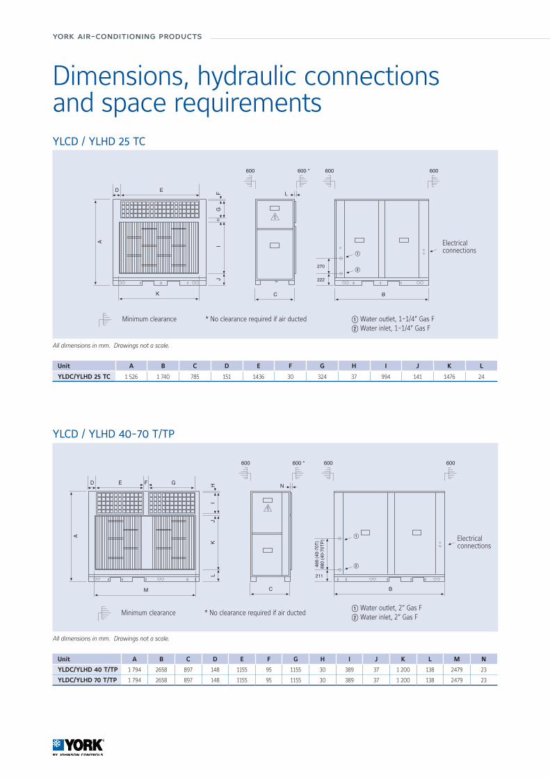
YLCD / YLHD 25 TC
Dimensions, hydraulic connectionsand space requirements
Unit A B C D E F G H I J K L M N
YLDC/YLHD 40 T/TP 1 794 2658 897 148 1155 95 1155 30 389 37 1 200 138 2479 23
YLDC/YLHD 70 T/TP 1 794 2658 897 148 1155 95 1155 30 389 37 1 200 138 2479 23
Electrical connections
Minimum clearance * No clearance required if air ducted
YLCD / YLHD 40-70 T/TP
All dimensions in mm. Drawings not a scale.
Unit A B C D E F G H I J K L
YLDC/YLHD 25 TC 1 526 1 740 785 151 1436 30 324 37 994 141 1476 24
Electrical connections
Minimum clearance * No clearance required if air ducted Q Water outlet, 1-1/4” Gas FW Water inlet, 1-1/4” Gas F
Q Water outlet, 2” Gas FW Water inlet, 2” Gas F
All dimensions in mm. Drawings not a scale.
A
C
D E
B
IH
JK
L
F G
M
N
600 *600 600600
466
(40-
70T)
880
(40-
70TP
)
211
Q
W
A
C
D E
B
270
222
Q
W
GF
HI
J
K
L
600 *600 600600

Wat
er S
yste
ms
22/23
YLCD / YLHD 100-120 T/TP
YLCD / YLHD 150 T/TP
YLCD-YLHD 25 to 150
Unit A B C D E F G H I J K L M N
YLDC/YLHD 100 T/TP 3 466 183 1 550 704 2 058 1 942 2 460 500 410 59 1 450 200 290 380
YLDC/YLHD 120 T/TP 3 416 183 1 525 604 2 208 1 942 2 460 500 418 55 1 438 200 290 380
Unit A B C D E F G H I J K L M N
YLDC/YLHD 150 T/TP 3 768 254 1 630 605 2 558 1 992 2 480 470 386 55 1 617 410 210 458
Q Water outlet, 2-1/2” Gas FW Water inlet, 2-1/2” Gas FE Diameter drain tube, 20 mm
Q Water outlet, 2-1/2” Gas FW Water inlet, 2-1/2” Gas FE Diameter drain tube, 20 mm
All dimensions in mm. Drawings not a scale.
All dimensions in mm. Drawings not a scale.
1
2
3
1
2
3

york air-conditioning products
YLAAAir-cooled scroll compressor chillerCooling capacities from 177 kW to 521 kW
FeaturesThe YORK YLAA TEMPO air-cooled chiller is an environmental leader.
Utilising scroll type compressors and microchannel condenser coil technology the YLAA delivers premium efficiency for all air conditioning applications.
YLAA chillers are a self-contained cooling solution that is light-weight and compact for convenient installation on the ground or on building rooftops.
There are 4 versions COOLING ONLY
YLAA SE Standard Efficiency
YLAA SE LS Standard Efficiency, Low sound
YLAA HE High EfficiencyYLAA HE LS High Efficiency, Low sound
Ultra quiet operation can be obtained through optional dual or low speed fans and a compressor accousitc enclosure.
A single point power connection and optional, factory packaged water pumps, water filter and flow switch provide fast and easy installation.
An optional heat recovery feature can be added to provide hot water to 50°C; which is useful for facility heating or hot water preheating.
The TEMPO delivers energy efficiency levels that surpasses Eurovent A Class requirements. Aluminun microchannel condenser coil technology is one reason for this premium efficiencies.
Supplies chilled liquid at temperatures between -1°C and 15°C.Operates in ambient temperatures from -18°C to 46°C fully loaded.

Manufacturer reserves the rights to change specifications without prior notice.
Wat
er S
yste
ms
24/25
YLAA HE High Efficiency 195 260 300 350 390 440 455 515Cooling capacity (kW) 196 253 310 346 386 429 451 521EER 3.08 3.03 3.10 3.10 3.03 3.04 3.07 3.06ESEER 4.39 4.72 4.14 3.99 4.15 4.14 4.17 4.33Sound pressure at 10 m (dBA) 57 61 61 62 63 63 64 64
YLAA HE LS High Efficiency & Low sound 195 260 300 350 390 440 455 515Cooling capacity (kW) 194 248 304 340 377 421 443 510EER 2.98 2.94 3.01 3.03 2.93 2.96 3.01 2.96ESEER 4.26 4.59 4.22 4.01 4.22 4.19 4.22 4.37Sound pressure at 10 m (dBA) (1) 49 55 54 55 56 56 57 57
At leaving chilled water temperature of 7°C, and ambient temperature of 35°C.(1) Low sound models with acoustically lined compressor enclosure, and fixed low speed fans.
Nominal capacityYLAA SE Standard 180 210 240 285 320 360 400 435 485Cooling capacity (kW) 179 196 218 276 310 344 386 418 466EER 2.84 2.41 2.69 2.71 2.56 2.66 2.55 2.69 2.57ESEER 3.95 3.42 3.65 4.09 3.97 3.94 3.79 3.92 3.83Sound pressure at 10 m (dBA) 57 58 59 61 62 62 62 64 64
YLAA SE LS Standard & Low sound 180 210 240 285 320 360 400 435 485Cooling capacity (kW) 177 193 214 269 301 336 374 408 452EER 2.75 2.30 2.63 2.59 2.42 2.54 2.41 2.57 2.43ESEER 3.88 3.34 3.67 4.01 3.89 3.96 3.79 3.89 3.80Sound pressure at 10 m (dBA) (1) 49 50 52 55 55 55 55 57 57
Technical dataYLAA SE Standard 180 210 240 285 320 360 400 435 485
DimensionsLength mm 2911 3690Width mm 2242Height mm 2508
Operating weight kg 1715 1749 1848 2367 2469 3254 3339 3108 3290
YLAA SE LS Standard & Low sound 180 210 240 285 320 360 400 435 485
DimensionsLength mm 2911 3690Width mm 2242Height mm 2508
Operating weight kg 1871 1905 2004 2523 2625 3449 3534 3303 3485
YLAA HE High Efficiency 195 260 300 350 390 440 455 515
DimensionsLength mm 2911 3690 4807Width mm 2242Height mm 2508
Operating weight kg 2165 2328 3041 2805 3151 3833 3902 4192
YLAA HE LS High Efficiency & Low sound 195 260 300 350 390 440 455 515
DimensionsLength mm 2911 3690 4807Width mm 2242Height mm 2508
Operating weight kg 2321 2484 3236 3000 3346 4028 4097 4387
Air-cooled scroll compressor chiller YLAA 180 to 515
york air-conditioning products
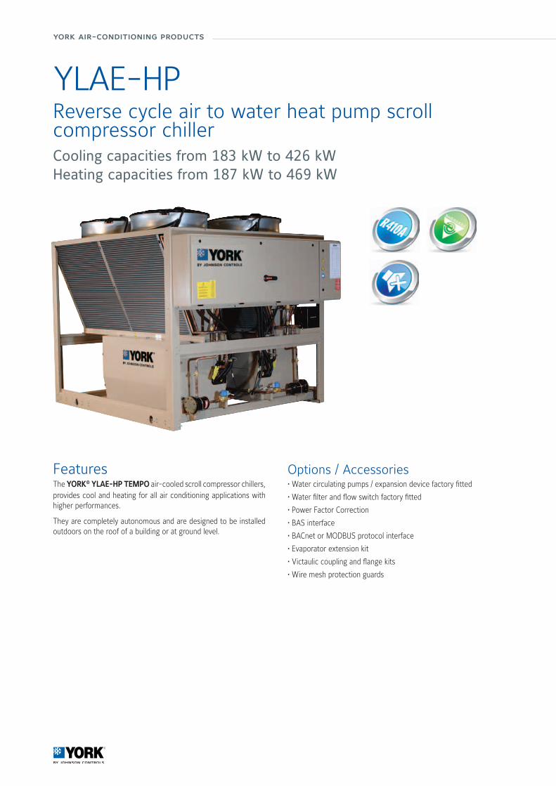
YLAE-HPReverse cycle air to water heat pump scroll compressor chillerCooling capacities from 183 kW to 426 kWHeating capacities from 187 kW to 469 kW
FeaturesThe YORK® YLAE-HP TEMPO air-cooled scroll compressor chillers, provides cool and heating for all air conditioning applications with higher performances.
They are completely autonomous and are designed to be installed outdoors on the roof of a building or at ground level.
Options / Accessories• Water circulating pumps / expansion device factory fitted
• Water filter and flow switch factory fitted
• Power Factor Correction
• BAS interface
• BACnet or MODBUS protocol interface
• Evaporator extension kit
• Victaulic coupling and flange kits
• Wire mesh protection guards
Manufacturer reserves the rights to change specifications without prior notice.
Wat
er S
yste
ms
26/27
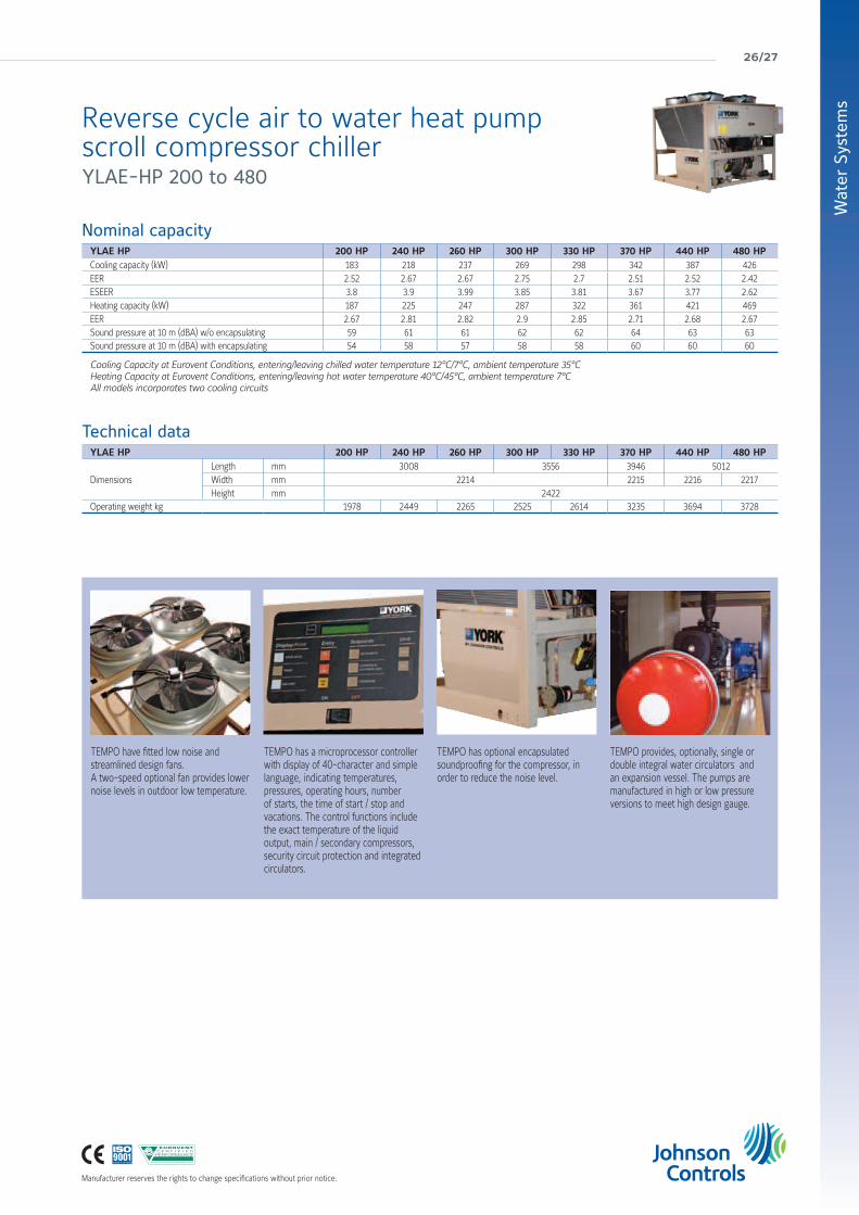
Technical dataYLAE HP 200 HP 240 HP 260 HP 300 HP 330 HP 370 HP 440 HP 480 HP
DimensionsLength mm 3008 3556 3946 5012Width mm 2214 2215 2216 2217Height mm 2422
Operating weight kg 1978 2449 2265 2525 2614 3235 3694 3728
Reverse cycle air to water heat pump scroll compressor chiller YLAE-HP 200 to 480
TEMPO have fitted low noise and streamlined design fans.A two-speed optional fan provides lower noise levels in outdoor low temperature.
TEMPO has a microprocessor controller with display of 40-character and simple language, indicating temperatures, pressures, operating hours, number of starts, the time of start / stop and vacations. The control functions include the exact temperature of the liquid output, main / secondary compressors, security circuit protection and integrated circulators.
TEMPO has optional encapsulated soundproofing for the compressor, in order to reduce the noise level.
TEMPO provides, optionally, single or double integral water circulators and an expansion vessel. The pumps are manufactured in high or low pressure versions to meet high design gauge.
Nominal capacityYLAE HP 200 HP 240 HP 260 HP 300 HP 330 HP 370 HP 440 HP 480 HP Cooling capacity (kW) 183 218 237 269 298 342 387 426EER 2.52 2.67 2.67 2.75 2.7 2.51 2.52 2.42ESEER 3.8 3.9 3.99 3.85 3.81 3.67 3.77 2.62Heating capacity (kW) 187 225 247 287 322 361 421 469EER 2.67 2.81 2.82 2.9 2.85 2.71 2.68 2.67Sound pressure at 10 m (dBA) w/o encapsulating 59 61 61 62 62 64 63 63Sound pressure at 10 m (dBA) with encapsulating 54 58 57 58 58 60 60 60
Cooling Capacity at Eurovent Conditions, entering/leaving chilled water temperature 12°C/7°C, ambient temperature 35°CHeating Capacity at Eurovent Conditions, entering/leaving hot water temperature 40°C/45°C, ambient temperature 7°CAll models incorporates two cooling circuits

york air-conditioning products
YLPAHeat pump scroll compressorCooling capacities from 342 kW to 647 kWHeating capacities from 351 kW to 666 kWAt Eurovent Standard Conditions most high efficiency models meet A Class energy efficiency levels.
FeaturesThe YLPA heat pump delivers premium energy efficiency, it is easy to install, quiet to run, and it is supported by a knowledgable service force.
EfficiencyEurovent A-Class certified full load efficiency, high part load efficiency, improved defrost cycle, extended operating envelope. Maximize heating efficiency and renewable energy use with the YLPA heat pump.
SoundDesigned for quiet operation at full and part load conditions.
SustainabilityEuropean Commission 2020 renewables targets compliant, specifically designed for HFC-410A.
Ease of installationQuick and easy to install, compact design, Metasys® ready.
ReliabilityThe YLPA is our third generation of fully factory tested scroll heat pumps, and thanks to our extensive service solutions, support and minimal maintenance are assured.
Multiple scroll design enables sound reduction during part load operation by simply turning off unnecessary compressors

Manufacturer reserves the rights to change specifications without prior notice.
Wat
er S
yste
ms
28/29
Nominal capacityYLPA SE Standard 340 415 495 560 610Cooling capacity (kW) 342 424 513 568 636
Cooling EER 3.08 3.01 3.00 2.96 2.97
ESEER 4.0 4.1 4.1 3.9 3.9
Heating capacity (kW) 351 439 527 581 666
Heating EER 3.11 3.18 3.19 3.17 3.10
Sound pressure at 10 m (dBA) 54 55 56 55 56
YLPA HE High Efficiency 355 425 505 570 640Cooling capacity (kW) 359 444 526 590 647
Cooling EER 3.26 3.24 3.23 3.11 3.02
ESEER 4.5 4.5 4.6 4.4 4.4
Heating capacity (kW) 369 460 554 600 666
Heating EER 3.27 3.22 3.20 3.24 3.23
Sound pressure at 10 m (dBA) 55 55 55 56 56
Cooling Capacity at Eurovent Conditions, entering/leaving chilled water temperature 12°C/7°C, ambient temperature 35°CHeating Capacity at Eurovent Conditions, entering/leaving hot water temperature 40°C/45°C, ambient temperature 7°CSound Pressure according to Eurovent conditions. LS models
Technical dataYLPA SE Standard 340 415 495 560 610
Dimensions
Length mm 4937 5854 6971
Width mm 2246
Height mm 2501
Operating weight kg 4600 5000 5200 5695 6235
YLPA HE High Efficiency 355 425 505 570 640
Dimensions
Length mm 4937 5854 6971
Width mm 2246
Height mm 2501
Operating weight kg 4750 5400 6100 6495 6695
Additional Energy Savings in Heating Mode
Heat Pump efficiencyRunning cost
(Euros/kWh of useful heat)
Typical Boilertoday
YLPAHeat Pump
Energy Rate: Electricity 0.1 EUR / kWh; Gas 0.03 EUR / kWh
0.0
0.5
10%
1.5
2.5
1.0
2.0
3.0
3.5 -0.035
-0.033
-0.031
-0.029
-0.027
-0.025
High Efficiency Cooling Mode
Heat Pump efficiency (ESEER) Annual energy cost
Typical 10-15 yearold Heat Pump
Typical Heat Pumptoday
YLPAHeat Pump
500 kW unit, 3000 operating hours, energy rate = 0.1 EUR / kWh
3.1
3.3
39%
17%
3.7
4.1
3.5
3.9
4.3
4.5
4.7 - €27,000
- €25,000
- €23,000
- €21,000
- €19,000
- €17,000
- €15,000
Heat pump scroll compressor YLPA 340 to 640

york air-conditioning products
YVAAAir-cooled VSD screw chillerCooling capacities from 525 kW to 1225 kWAt Eurovent Standard Conditions this equipment meets A Class energy efficiency levels.
Features• Reduce your annual energy costs by as much as 30% • Reduce your sound levels by up to 16 dBA to meet tighter regulations • Enhance your flexibility with a variety of chiller options to fit your needs • Minimise your environmental impact dramatically • Lower your part load energy and night time sound levels with inverter fans and compressors
• Deliver increased motor longevity and increased chiller reliability with low starting currents
• Cut your operational expenses with a high chiller power factor at all loads • Improve your peace of mind knowing we stand behind every chiller
Reduce refrigerant charges by up to 15% beyond traditional chiller designs with the YVAA’s falling-film evaporator and microchannel condenser coil technology.
Phot
o co
urte
sy o
f the
LTCM
lab
of th
e Ec
ole
Polyt
echn
ique
Féd
érale
de
Laus
anne
, Sw
itzer
land
A more efficient chiller means less electricity generation, which reduces greenhouse gas emissions, water consumption – and your environmental footprint.The sustainability advantages of the YVAA chiller give you the opportunity to earn points in the LEED® and BREEAM® building certification programs.
Manufacturer reserves the rights to change specifications without prior notice.
Wat
er S
yste
ms
30/31
Air-cooled VSD screw chiller YVAA
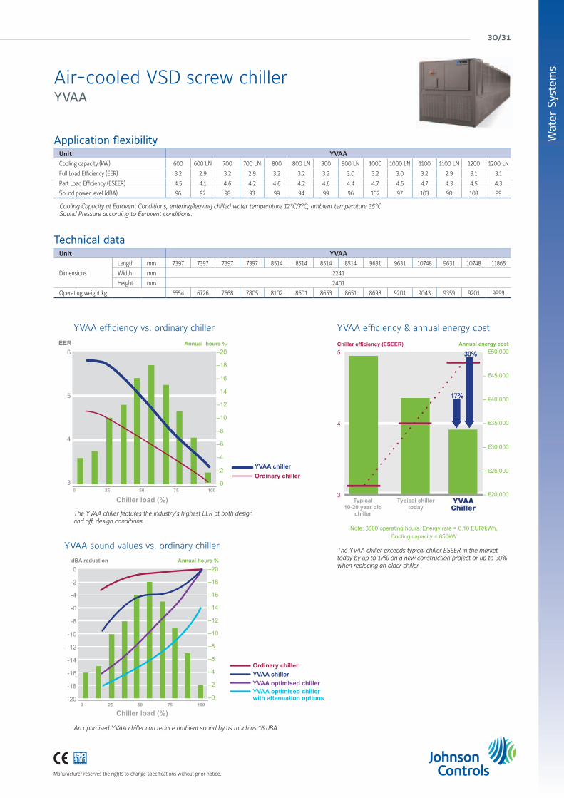
Application flexibilityUnit YVAACooling capacity (kW) 600 600 LN 700 700 LN 800 800 LN 900 900 LN 1000 1000 LN 1100 1100 LN 1200 1200 LN
Full Load Efficiency (EER) 3.2 2.9 3.2 2.9 3.2 3.2 3.2 3.0 3.2 3.0 3.2 2.9 3.1 3.1
Part Load Efficiency (ESEER) 4.5 4.1 4.6 4.2 4.6 4.2 4.6 4.4 4.7 4.5 4.7 4.3 4.5 4.3
Sound power level (dBA) 96 92 98 93 99 94 99 96 102 97 103 98 103 99
Cooling Capacity at Eurovent Conditions, entering/leaving chilled water temperature 12°C/7°C, ambient temperature 35°CSound Pressure according to Eurovent conditions.
Technical dataUnit YVAA
Dimensions
Length mm 7397 7397 7397 7397 8514 8514 8514 8514 9631 9631 10748 9631 10748 11865
Width mm 2241
Height mm 2401
Operating weight kg 6554 6726 7668 7805 8102 8601 8653 8651 8698 9201 9043 9359 9201 9999
The YVAA chiller features the industry’s highest EER at both design and off-design conditions.
An optimised YVAA chiller can reduce ambient sound by as much as 16 dBA.
YVAA efficiency vs. ordinary chiller
YVAA sound values vs. ordinary chiller The YVAA chiller exceeds typical chiller ESEER in the market today by up to 17% on a new construction project or up to 30% when replacing an older chiller.
5
4
3
30%
17%
– €50,000
– €45,000
– €40,000
– €35,000
– €30,000
– €25,000
– €20,000
YVAA efficiency & annual energy cost
–20
–18
–16
–14
–12
–10
–8
–6
–4
–2
–0
6
5
4
3
EER
0 25 50 75 100
–20
–18
–16
–14
–12
–10
–8
–6
–4
–2
–0
0
-2
-4
-6
-8
-10
-12
-14
-16
-18
-200 25 50 75 100
Chiller efficiency (ESEER)
Ordinary chiller
Ordinary chiller
YVAA chiller
YVAA chillerYVAA optimised chillerYVAA optimised chillerwith attenuation options
Annual energy costAnnual hours %
Annual hours %dBA reduction
Note: 3500 operating hours, Energy rate = 0.10 EUR/kWh,Cooling capacity = 850kW
Typical 10-20 year old
chiller
Chiller load (%)
Chiller load (%)
Typical chillertoday
YVAAChiller

york air-conditioning products
Manufacturer reserves the rights to change specifications without prior notice.
YMWA / YMRAWater-cooled cooling only, remote condenser and heat pump scroll compressor chillerCooling capacities from 20 kW to 190 kW
Features• Scroll compressors (single or tandem)• Higher EER and COP• 2 different frames / configurations: · 1 compressor / 1 circuit up to 45 kW · 2 compressors / 1 circuit from 50 to 190 kW• Reduced refrigerant charge• Condensing pressure control• “Plug and Play” units
Available versions14 available YMWA sizes in three versions:
1) YMWA-CO : Cooling only
2) YMRA : Remote condenser
3) YMWA-HP : Heat pump
Nominal capacity and technical dataYMWA-CO 20 25 30 35 40 45 50 60 75 90 120 150 170 190
Cooling Capacity (kW) 21.3 26.4 31.3 35.1 39.5 46.9 51.1 61.3 77.6 91.4 118.8 147.5 170.5 193.3
EER 4.58 4.54 4.46 4.53 4.48 4.57 4.29 4.48 4.48 4.38 4.46 4.46 4.50 4.51
Length /Width / Height (mm) 821 / 455 / 1350 1210 / 850 / 1500
Operating weight (kg) 156 176 174 179 185 203 440 491 540 591 837 966 1041 1145
YMRA 20 25 30 35 40 45 50 60 75 90 120 150 170 190
Cooling Capacity (kW) 20.9 26.0 31.3 34.8 39.3 46.2 51.2 61.7 77.8 91.4 118.7 147.6 169.4 193.2
Length /Width / Height (mm) 821 / 455 / 1350 1210 / 850 / 1500
Operating weight (kg) 144 164 166 166 172 172 376 404 439 466 678 762 813 874
YMWA-HP 20 25 30 35 40 45 50 60 75 90 120 150 170 190
Cooling Capacity (kW) 20.9 26.1 30.3 34.2 38.4 45.8 50.2 59.2 76.4 89.0 115.3 144.8 166.3 186.1
Heating Capacity (kW) 23.5 28.6 33.4 38.2 42.6 50.6 57.2 67.5 85.5 101.2 130.7 162.8 188.3 210.3
EER / COP 4.45/4.03 4.47/4.00 4.28/3.93 4.35/3.96 4.34/3.95 4.39/4.00 4.18/4.03 4.27/3.98 4.38/4.09 4.22/4.06 4.28/4.08 4.35/4.13 4.36/4.11 4.29/4.10
Length /Width / Height (mm) 821 / 455 / 1350 1210 / 850 / 1500
Operating weight (kg) 159 181 179 184 190 208 448 499 551 602 850 983 1058 1162
YMWA-CO: Standard Eurovent LCP/W/AC conditions in cooling mode: evaporator EWT/LWT 12°C/7°C, condenser EWT/LWT 30°C/35°CYMRA: Evaporator EWT/LWT 12°C/7°C, condensing temperature 40°CYMWA-HP: Standard Eurovent LCP/W/AC conditions in cooling mode: evaporator EWT/LWT 12°C/7°C, condenser EWT/LWT 30°C/35°CYMWA-HP: Standard Eurovent LCP/W/AC conditions in heating mode: evaporator EWT/LWT 10°C, condenser EWT/LWT 40°C/45°C
Same cabinet w/o or with factory mounted hydrokit (one or two pumps).More compact and slim.
NEW

Manufacturer reserves the rights to change specifications without prior notice.
Wat
er S
yste
ms
32/33
YCSEWater-cooled or remote air-cooledscrew compressor chillerCooling capacities from 134 kW to 320 kW
FeaturesEfficient screw compressorsHighly efficient the YCSE offers the highest standard of reliability and economical operation utilising twin-screw rotor technology and fully modulating compressor slide valve unloading, together with low inrush current star delta starters. To further improve the operating efficiency the leaving liquid temperature can be remotely reset.
Quiet operationThe compressor has been designed so that there is minimal external gas pulsations and integral oil separators resulting in very low sound and vibration levels.
Small footprint and robust designThe compact design is ideally suited for reduced base area locations. Both single and twin circuit designs require a single liquid inlet and oulet connection. The unit frame is manufactured from heavy gauge galvanised steel coated with baked-on powder paint.
Options / Accessories• Remote control switch unit.• BMS interface.• Compressor circuit breakers.• Evaporator heater.• Flow switch.• Differential pressure switches.• Suction pressure relief valves.• Anti-vibration rubber mounts.• Water connection flanges.• Discharge and/or suction stop valves.• High condenser water temperature and glycol options.
Nominal capacity and technical dataYCSE-SB Model 40 50 60 80 100
Cooling Capacity (kW) 134 160 194 232 320
EER 4.00 4.00 3.95 4.26 4.00
Sound pressure at 1 m (dBA) 68 69 71 71 72
Length /Width / Height (m) 0.85 / 1.1 / 1.5 1.5 / 1.1 / 1.7
Operating weight (kg) 780 800 875 1000 1655
At 7°C leaving chilled water and 35°C leaving condenser water.
york air-conditioning products
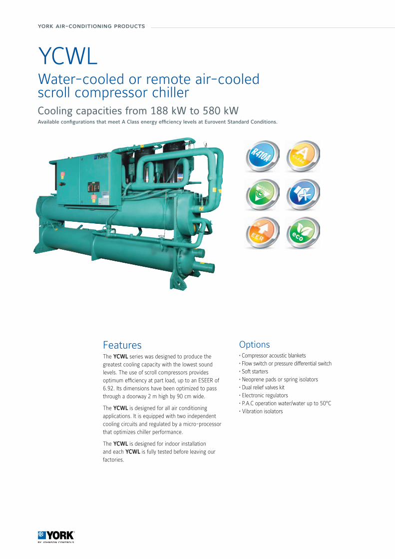
YCWLWater-cooled or remote air-cooledscroll compressor chillerCooling capacities from 188 kW to 580 kWAvailable configurations that meet A Class energy efficiency levels at Eurovent Standard Conditions.
FeaturesThe YCWL series was designed to produce the greatest cooling capacity with the lowest sound levels. The use of scroll compressors provides optimum efficiency at part load, up to an ESEER of 6.92. Its dimensions have been optimized to pass through a doorway 2 m high by 90 cm wide.
The YCWL is designed for all air conditioning applications. It is equipped with two independent cooling circuits and regulated by a micro-processor that optimizes chiller performance.
The YCWL is designed for indoor installation and each YCWL is fully tested before leaving our factories.
Options• Compressor acoustic blankets• Flow switch or pressure differential switch• Soft starters• Neoprene pads or spring isolators• Dual relief valves kit• Electronic regulators• P.A.C operation water/water up to 50°C• Vibration isolators
Manufacturer reserves the rights to change specifications without prior notice.
Wat
er S
yste
ms
34/35
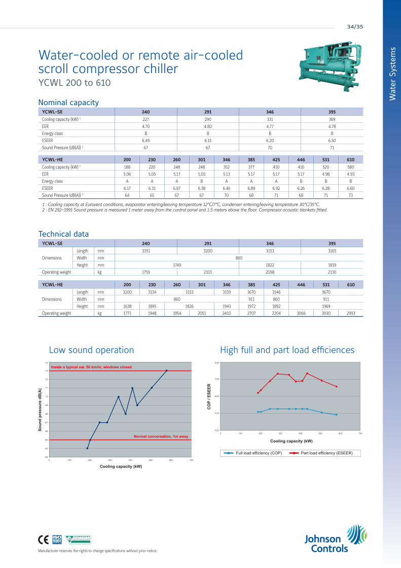
High full and part load efficiencesLow sound operation
Technical dataYCWL-SE 240 291 346 395
Dimensions
Length mm 3191 3200 3153 3165
Width mm 860
Height mm 1749 1822 1819
Operating weight kg 1759 2101 2098 2130
Nominal capacityYCWL-SE 240 291 346 395
Cooling capacity (kW) 1 227 290 331 369
EER 4.70 4.80 4.77 4.78
Energy class B B B B
ESEER 6.49 6.15 6.20 6.50
Sound Pressure (dB(A)) 2 67 67 70 71
YCWL-HE 200 230 260 301 346 385 425 446 531 610
Cooling capacity (kW) 1 188 220 248 248 352 377 410 410 520 580
EER 5.06 5.05 5.17 5.03 5.13 5.17 5.17 5.17 4.98 4.93
Energy class A A A B A A A B B B
ESEER 6.17 6.31 6.87 6.38 6.46 6.89 6.92 6.26 6.28 6.60
Sound Pressure (dB(A)) 2 64 65 67 67 70 68 71 69 71 73
1 : Cooling capacity at Eurovent conditions, evaporator entering/leaving temperature 12°C/7°C, condenser entering/leaving temperature 30°C/35°C.2 : EN 292-1991 Sound pressure is measured 1 meter away from the control panel and 1.5 meters above the floor. Compressor acoustic blankets fitted.
YCWL-HE 200 230 260 301 346 385 425 446 531 610
Dimensions
Length mm 3200 3134 3153 3159 3670 3146 3670
Width mm 860 911 860 911
Height mm 1638 1895 1826 1943 1972 1892 1969
Operating weight kg 1771 1948 1954 2051 2410 2707 2204 3066 3030 2993
Inside a typical car, 50 km/hr, windows closed
Normal conversation, 1m away
Cooling capacity (kW)
Cooling capacity (kW)
Soun
d pr
essu
re d
B(A
)
CO
P / E
SEER
Full load efficiency (COP) Part load efficiency (ESEER)
Water-cooled or remote air-cooledscroll compressor chiller YCWL 200 to 610
york air-conditioning products
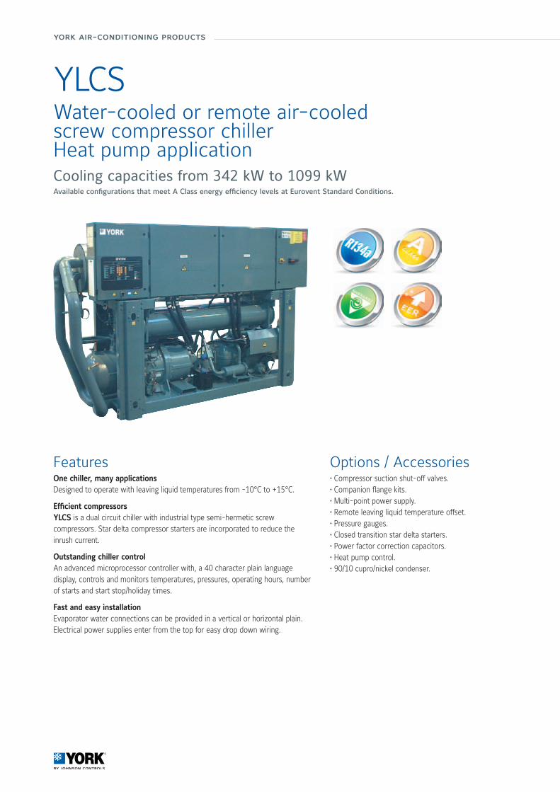
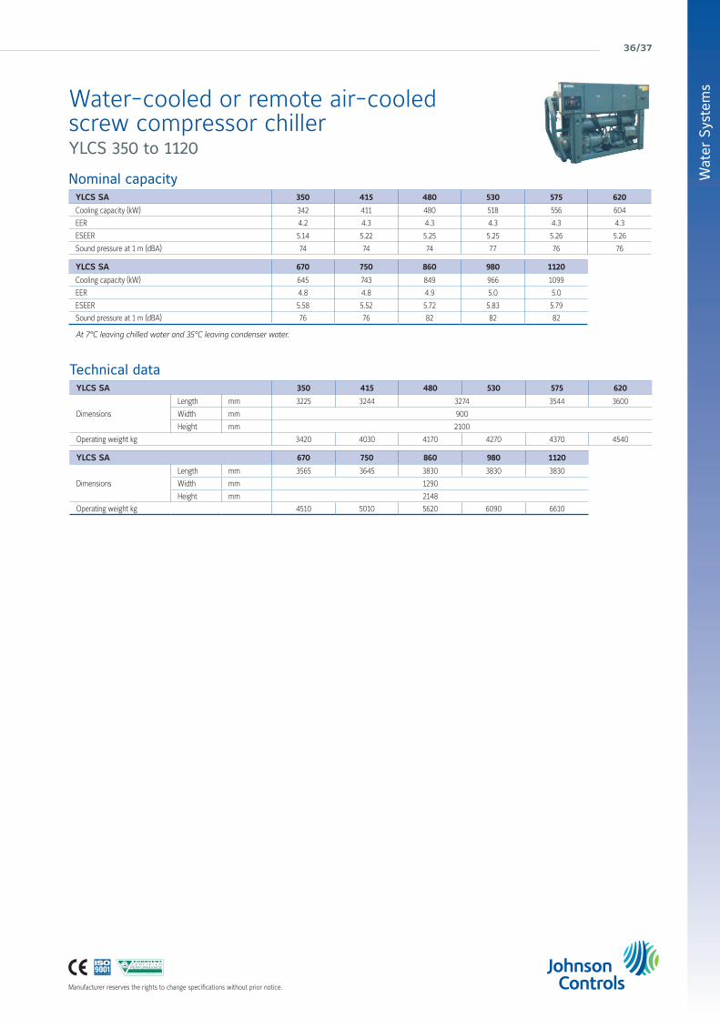
YLCS
FeaturesOne chiller, many applicationsDesigned to operate with leaving liquid temperatures from -10°C to +15°C.
Efficient compressorsYLCS is a dual circuit chiller with industrial type semi-hermetic screw compressors. Star delta compressor starters are incorporated to reduce the inrush current.
Outstanding chiller controlAn advanced microprocessor controller with, a 40 character plain language display, controls and monitors temperatures, pressures, operating hours, number of starts and start stop/holiday times.
Fast and easy installationEvaporator water connections can be provided in a vertical or horizontal plain.Electrical power supplies enter from the top for easy drop down wiring.
Options / Accessories• Compressor suction shut-off valves.• Companion flange kits.• Multi-point power supply.• Remote leaving liquid temperature offset.• Pressure gauges.• Closed transition star delta starters.• Power factor correction capacitors.• Heat pump control.• 90/10 cupro/nickel condenser.
Water-cooled or remote air-cooledscrew compressor chillerHeat pump applicationCooling capacities from 342 kW to 1099 kWAvailable configurations that meet A Class energy efficiency levels at Eurovent Standard Conditions.
Manufacturer reserves the rights to change specifications without prior notice.
Wat
er S
yste
ms
36/37
Nominal capacityYLCS SA 350 415 480 530 575 620
Cooling capacity (kW) 342 411 480 518 556 604
EER 4.2 4.3 4.3 4.3 4.3 4.3
ESEER 5.14 5.22 5.25 5.25 5.26 5.26
Sound pressure at 1 m (dBA) 74 74 74 77 76 76
YLCS SA 670 750 860 980 1120
Cooling capacity (kW) 645 743 849 966 1099
EER 4.8 4.8 4.9 5.0 5.0
ESEER 5.58 5.52 5.72 5.83 5.79
Sound pressure at 1 m (dBA) 76 76 82 82 82
At 7°C leaving chilled water and 35°C leaving condenser water.
Technical dataYLCS SA 350 415 480 530 575 620
Dimensions
Length mm 3225 3244 3274 3544 3600
Width mm 900
Height mm 2100
Operating weight kg 3420 4030 4170 4270 4370 4540
YLCS SA 670 750 860 980 1120
Dimensions
Length mm 3565 3645 3830 3830 3830
Width mm 1290
Height mm 2148
Operating weight kg 4510 5010 5620 6090 6610
Water-cooled or remote air-cooledscrew compressor chiller YLCS 350 to 1120

york air-conditioning products
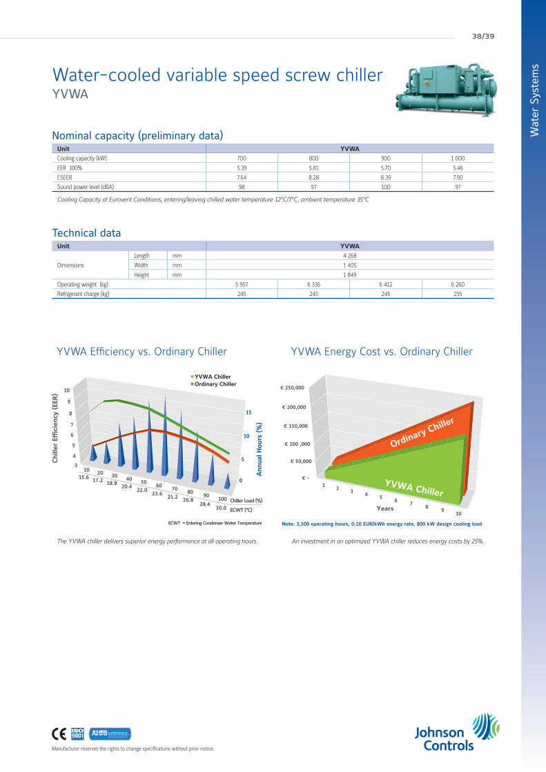
Water-cooled variable speed screw chillerCooling capacities from 703 kW to 1055 kWAt Eurovent Standard Conditions this equipment meets A Class energy efficiency levels.
FeaturesOur newest water-cooled chiller offers the following benefits:
Premium efficiencyThe YVWA reduces operating expenses with the application of a standard variable speed drive.
Application flexibilityTailor and tune flexilibilty makes the YVWA ideal for any application from thermal storage to heat pump duty.
Enhanced sustainabilityAchieved through high efficiency operation and low refrigerant charges.
Product confidenceImprove your peace of mind knowing our experience stands behind every chiller.
Reduce refrigerant charges by up to 15% beyond traditoinal chiller designs with the YVWA’s falling film evaporator design.
Phot
o co
urte
sy o
f the
LTCM
lab
of th
e Ec
ole
Polyt
echn
ique
Féd
érale
de
Laus
anne
, Sw
itzer
land
YVWA
The YVWA chiller can efficiently handle the high condenser pressure required for dry cooling.
Phot
o co
urte
sy o
f Balt
imor
e Ai
r Coi
l.
NEW
Manufacturer reserves the rights to change specifications without prior notice.
Wat
er S
yste
ms
38/39
Nominal capacity (preliminary data)Unit YVWA Cooling capacity (kW) 700 800 900 1 000
EER 100% 5.39 5.81 5.70 5.46
ESEER 7.64 8.28 8.39 7.90
Sound power level (dBA) 98 97 100 97
Cooling Capacity at Eurovent Conditions, entering/leaving chilled water temperature 12°C/7°C, ambient temperature 35°C
Technical dataUnit YVWA
Dimensions
Length mm 4 268
Width mm 1 405
Height mm 1 849
Operating weight (kg) 5 957 6 336 6 412 6 260
Refrigerant charge (kg) 245 245 245 255
The YVWA chiller delivers superior energy performance at all operating hours.
YVWA Efficiency vs. Ordinary Chiller YVWA Energy Cost vs. Ordinary Chiller
An investment in an optimized YVWA chiller reduces energy costs by 25%.
YVWA Efficiency vs. Ordinary Chiller
Ordinary ChillerYVWA Chiller
0
5
10
15
Chi
ller
Effici
ency
(EE
R)
3
4
5
6
7
8
9
10
Chiller Load (%)
ECWT (°C)
ECWT = Entering Condenser Water Temperature
10 20 3040
5060
7080
90100
15.6 17.2 18.820.4
22.023.6
25.226.8
28.430.0
Ann
ual H
ours
(%
)
YVWA Energy Cost vs. Ordinary Chiller
1 2 3 4 5 67
89
10Years
-
50,000
100 ,000
150,000
200,000
250,000
YVWA Chiller
Ordinary Chiller
Note: 3,500 operating hours, 0.10 EUR/kWh energy rate, 800 kW design cooling load
Water-cooled variable speed screw chiller YVWA

york air-conditioning products
YNWater-cooled screw compressor chillerDry cooler application - Heat recovery application Heat pump applicationCooling capacities from 570 kW to 1300 kWAt Eurovent Standard Conditions this equipment meets A Class energy efficiency levels.
FeaturesHigh Efficiency Screw CompressorThe open drive twin rotary screw compressor has been engineered and constructed to meet the exact requirements of the industrial refrigeration market. It utilises state-of-the-art technology to provide the most reliable compressor, with high energy efficiency at all operating conditions.
Heat ExchangersShells - The flooded type evaporator and condenser shells are fabricated from rolled carbon steel plates with fusion welded seams. Carbon steel tube sheets, drilled and reamed to accommodate the tubes, are welded to the end of each shell. Intermediate tube supports are fabricated from 12 mm carbon steel plates.Tubes - The copper alloy heat exchanger tubes are externally and internally enhanced to provide optimum performance.
Smooth and accurate capacity controlCapacity control is achieved by use of a slide valve which provides fully modulating control from 100% to 10% of full load, depending upon the unit selection. The slide valve is actuated by oil pressure controlled by external solenoid valves via the OptiView control centre.Equipped with the optional Solid State Starter, the YN screw chiller starts “softly,” putting less stress on the motor and compressor, extending their life. In addition, the Solid State Starter includes an impressive array of safety controls that protect the chiller against: phase loss, phase reversal, phase imbalance, under-voltage, overvoltage, and over-current

Manufacturer reserves the rights to change specifications without prior notice.
Wat
er S
yste
ms
40/41
Nominal capacityYN Model RB RB S2 RB RD S2 RD RB S2 RD RD S2 RB RB S3 RB RD S3 RD RB S3 RD RD S3 RB RB S4 RB RD S4 RD RB S4
Cooling Capacity kW 576 576 585 585 750 751 769 770 970 971 999
EER 5.65 5.72 5.75 5.81 5.42 5.51 5.56 5.66 5.29 5.43 5.46
ESEER 5.88 5.94 5.98 6.03 5.68 5.75 5.82 5.89 5.72 5.82 5.89
Class EER A A A A A A A A A A A
YN Model RD RD S4 SA SA S4 SA SD S4 SD SA S4 SD SD S4 RD RB S5 RD RD S5 SA SA S5 SA SD S5 SD SA S5 SD SD S5
Cooling Capacity kW (1) 1001 1036 1037 1054 1055 1231 1235 1285 1286 1316 1318
EER 5.6 5.9 6.07 6.01 6.19 5.22 5.39 5.74 5.97 5.89 6.13
ESEER 5.99 6.26 6.39 6.37 6.51 5.67 5.82 6.1 6.28 6.23 6.42
Class EER A A A A A A A A A A A
At 7°C leaving chilled water and 32°C leaving condenser water.
Technical dataYN Model RB RB S2 RB RD S2 RD RB S2 RD RD S2 RB RB S3 RB RD S3 RD RB S3 RD RD S3 RB RB S4 RB RD S4 RD RB S4
Dimensions
Length mm 3580
Width mm 1549
Height mm 2400
Operating weight kg 5017 5127 5157 5267 5097 5207 5237 5347 5476 5586 5616
YN Model RD RD S4 SA SA S4 SA SD S4 SD SA S4 SD SD S4 RD RB S5 RD RD S5 SA SA S5 SA SD S5 SD SA S5 SD SD S5
Dimensions
Length mm 3580 4211 3580 4211
Width mm 1549 1676 1585 1700
Height mm 2400 2500 2410 2500
Operating weight kg 5726 6919 7408 7160 7649 5787 5897 7090 7579 7331 7820
Water-cooled screw compressor chiller YN

york air-conditioning products
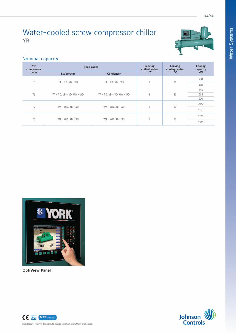
YRWater-cooled screw compressor chillerCooling capacities from 730 kW to 1320 kWAvailable configurations that meet A Class energy efficiency levels at Eurovent Standard Conditions.
Features• The YORK YR chiller has been designed to match the exact building load and lift requirements, which means it will always operate at peak efficiency when operating at Real World operating conditions.
• Equipped with the optional Solid State Starter, the YR screw chiller starts “softly,” putting less stress on the motor and compressor, extending motor life.
• The semi-hermetic YR chiller is designed for all air conditioning applications
• The twin rotary screw compressor driven YORK YR chiller is completely factory mounted , including: evaporator, condenser, subcooler, oil separator, compressor, motor, lubrication system, control panel, as well as all interconnecting piping and wiring.
• Flooded type evaporator and condenser shells are fabricated from rolled carbon steel plates with fusion welded seams.
Manufacturer reserves the rights to change specifications without prior notice.
Wat
er S
yste
ms
42/43
OptiView Panel
Nominal capacityYR
compressor code
Shell codes Leavingchilled water
°C
Leavingcooling water
°C
Cooling capacity
kWEvaporator Condenser
T0 TA - TD, VB - VD TA - TD, VB - VD 6 30730
770
T1 TA - TD, VB - VD, WA - WD TA - TD, VB - VD, WA - WD 6 30
859
905
920
T2 WA - WD, XB - XD WA - WD, XB - XD 6 301070
1110
T3 WA - WD, XB - XD WA - WD, XB - XD 6 301280
1320
Water-cooled screw compressor chiller YR

york air-conditioning products
Manufacturer reserves the rights to change specifications without prior notice.
YNWS/RSWater-cooled or remote air-cooledscrew compressor chillerCooling capacities from 470 kW to 1790 kWAvailable configurations that meet A Class energy efficiency levels at Eurovent Standard Conditions.
Features• The YNWS chiller is designed for all air conditioning applications.
• Both the water cooled YNWS and the remote air cooled YNRS models are designed for chilled water and process applications.
• Both models are designed for indoor mechanical room installation.
• The YNRS requires a cooling tower or an air-water condensing unit for heat dissipation.
• The screw compressor driven YNWS/RS chiller is completely factory mounted, including: direct expansion (DX) evaporator, condenser, subcooler, oil seperator, compressor, motor, lubrication system, control panel, as well as all interconnecting piping and wiring.
• R717 Refrigerant
Nominal capacity and technical dataYNWS Model DC FC SO DC GC S0 EC FC S0 EC GC S0 DC FC S1 DC GC S1 EC FC S1 EC GC S1 EC GC S2 EC HC S2 EC JC S2
Cooling Capacity (kW) 482 485 511 515 575 579 631 636 809 814 848
Length /Width / Height (m) 3.7/1.4/1.9 3.7/1.4/1.9 3.7/1.4/1.9 3.7/1.4/1.9 3.7/1.4/1.9 3.7/1.4/1.9 3.7/1.4/1.9 3.7/1.4/1.9 3.7/1.4/1.9 3.7/1.4/1.9 3.7/1.4/1.9
Operating weight (kg) 4114 4114 4114 4974 4150 4540 4540 5010 5449 5449 5449
YNWS Model FC JC S2 EC HC S3 EC JC S3 EC KC S3 FC HC S3 FC JC S3 FC KC S3 FC KC S4 FC LC S4 FC MC S4 FC NC S4
Cooling Capacity (kW) 856 1012 1015 1019 1084 1088 1093 1347 1352 1354 1395
Length /Width / Height (m) 3.7/1.451.9 3.7/1.4/2.0 3.7/1.4/2.0 3.7/1.4/2.0 3.7/1.4/2.0 3.7/1.4/2.0 3.8/1.5/2.3 3.9/1.6/2.3 3.9/1.6/2.3 3.9/1.6/2.3 3.9/1.6/2.3
Operating weight (kg) 6669 6010 6010 6010 6010 6010 7335 8412 8412 8412 8412
YNWS Model GC KC S4 GC LC S4 GC MC S4 GC NC S4 FC LC S5 FC MC S5 FC NC S5 GC LC S5 GC MC S5 GC NC S5
Cooling Capacity (kW) 1475 1481 1484 1488 1623 1625 1630 1780 1784 1790
Length /Width / Height (m) 3.9/1.6/2.3 3.9/1.6/2.3 3.9/1.6/2.3 3.9/1.8/2.5 3.9/1.7/2.3 3.9/1.7/2.3 3.9/1.7/2.3 3.9/1.7/2.3 3.9/1.7/2.3 3.9/1.8/2.5
Operating weight (kg) 8412 8412 8412 10142 9635 9635 10950 10950 10950 10950
At 6°C leaving chilled water and 32°C leaving condenser water.

Manufacturer reserves the rights to change specifications without prior notice.
Wat
er S
yste
ms
44/45
YNWHWater-cooled screw chillerCooling capacities from 300 kW to 1200 kWAvailable configurations that meet A Class energy efficiency levels at Eurovent Standard Conditions.
Features• The YNWH chiller is ideally suited for air conditioning, brine, and industrial applications.
• The water cooled YNWH is designed for brine based applications.
• This chiller is designed for indoor mechanical room installation.
• The YNWH requires a cooling tower or an air-water condensing unit for heat dissipation.
• The screw compressor driven YNWH chiller is completely factory mounted , including: direct expansion (DX) evaporator, condenser, subcooler, oil seperator, compressor, motor, lubrication system, control panel, as well as all interconnecting piping and wiring.
• R507 refrigerant
Nominal capacity and technical dataYNWH Model 16 12 S0 16 12 S1 20 20 S2 20 20 S3 28 24 S4 28 24 S5
Cooling Capacity (kW) 315 380 533 683 962 1169
Length /Width / Height (m) 3.7/1.5/1.7 3.7/1.5/1.7 3.9/1.6/2.0 3.9/1.6/2.0 4.3/2.0/2.3 4.4/2.0/2.3
Operating weight (kg) 3700 3900 6000 6300 9000 9800
Cooling capacity at -2°/-6°C brine application and 32°C condenser leaving water temperature

york air-conditioning products
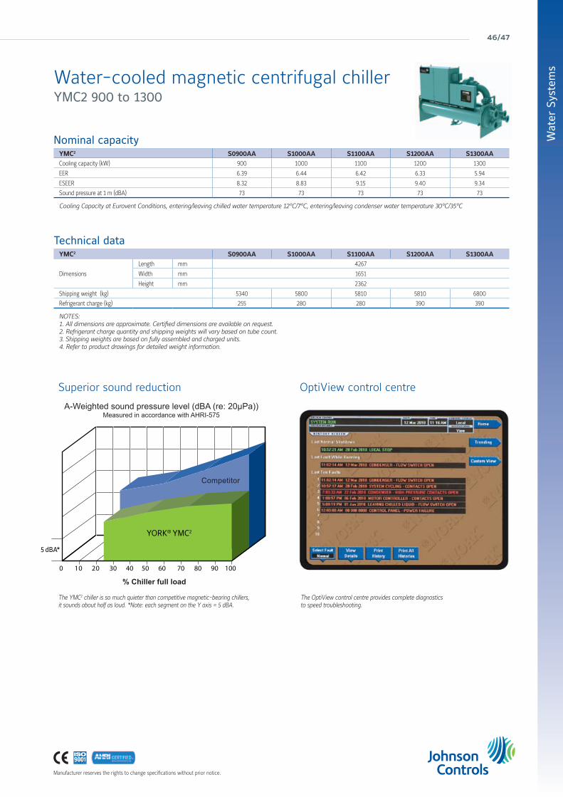
YMC2
Water-cooled magnetic centrifugal chillerCooling capacities from 755 kW to 1340 kWAt Eurovent Standard Conditions this equipment meets A Class energy efficiency levels.
FeaturesOur most advanced water-cooled chiller offers the following benefits:
Enhanced efficiencyAchieved through application of active magnetic bearing technology with variable speed drive.
Enhanced sustainabilityAchieved by leak free refrigerant design, lower refrigerant charge and falling film evaporator.
Low sound levelsAdvanced technology results in sound levels as low as 73dBA.
Superior reliabilityUse of active magnetic bearing technology removes friction and the need for oil resulting in a quieter and more reliable chiller.
A falling-film evaporator is more efficient because refrigerant is sprayed over the tubes, offering improved heat transfer and reducing refrigerant charge by 30%.
To eliminate mechanical-contact losses in the driveline, the YMC2 chiller utilises a permanent-magnet motor and active magnetic-bearing technology.
Phot
o co
urte
sy o
f the
LTCM
lab
of th
e Ec
ole
Polyt
echn
ique
Féd
érale
de
Laus
anne
, Sw
itzer
land
Manufacturer reserves the rights to change specifications without prior notice.
Wat
er S
yste
ms
46/47
Nominal capacityYMC2 S0900AA S1000AA S1100AA S1200AA S1300AACooling capacity (kW) 900 1000 1100 1200 1300
EER 6.39 6.44 6.42 6.33 5.94
ESEER 8.32 8.83 9.15 9.40 9.34
Sound pressure at 1 m (dBA) 73 73 73 73 73
Cooling Capacity at Eurovent Conditions, entering/leaving chilled water temperature 12°C/7°C, entering/leaving condenser water temperature 30°C/35°C
Technical dataYMC2 S0900AA S1000AA S1100AA S1200AA S1300AA
Dimensions
Length mm 4267
Width mm 1651
Height mm 2362
Shipping weight (kg) 5340 5800 5810 5810 6800
Refrigerant charge (kg) 255 280 280 390 390
NOTES:1. All dimensions are approximate. Certified dimensions are available on request.2. Refrigerant charge quantity and shipping weights will vary based on tube count.3. Shipping weights are based on fully assembled and charged units.4. Refer to product drawings for detailed weight information.
5 dBA*
YORK® YMC2
The YMC2 chiller is so much quieter than competitive magnetic-bearing chillers, it sounds about half as loud. *Note: each segment on the Y axis = 5 dBA.
Superior sound reduction OptiView control centre
The OptiView control centre provides complete diagnosticsto speed troubleshooting.
% Chiller full load
A-Weighted sound pressure level (dBA (re: 20µPa))Measured in accordance with AHRI-575
Competitor
Water-cooled magnetic centrifugal chiller YMC2 900 to 1300

york air-conditioning products
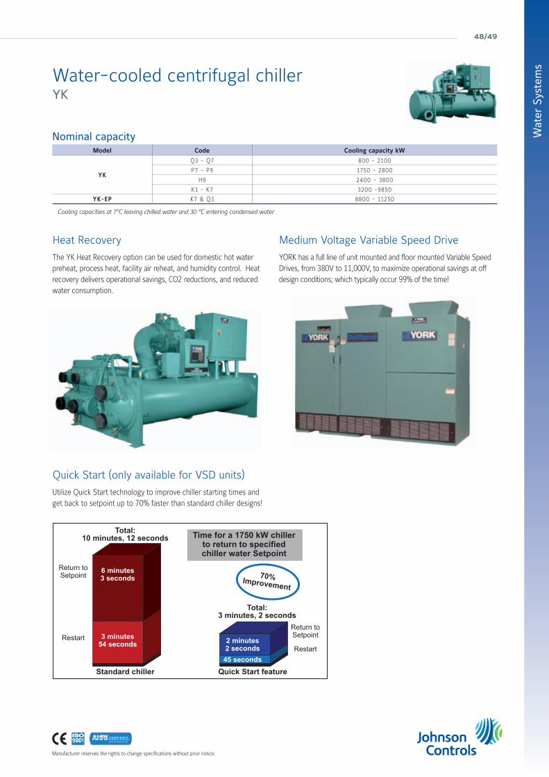
YKWater-cooled centrifugal chillerCooling capacities from 800 kW to 11250 kWAvailable configurations that meet A Class energy efficiency levels at Eurovent Standard Conditions.
Features• The YORK YK chiller is designed for air conditioning and process applications.
• The high efficiency single-stage centrifugal compressor is powered by an open-drive motor. This provides flexibility to operate the chiller with electricity, steam, or gas depending on utility rates.
• The YK utilizes a falling film evaporator to increase chiller efficiency and reduce refrigerant charges, which makes it ideal for LEED® building applications.
• This chiller is designed for indoor mechanical room installation and it requires a cooling tower for heat dissipation
• The inherent design flexibility of this chiller allows it to be precisely selected for any building load profile.
OptiView panel Speed comparison
Constant speedVariable speed
Cooling capacity
EER
Coo
ling
capa
city
/ po
wer
inpu
t
Manufacturer reserves the rights to change specifications without prior notice.
Wat
er S
yste
ms
48/49
Nominal capacityModel Code Cooling capacity kW
YK
Q3 - Q7 800 - 2100
P7 - P9 1750 - 2800
H9 2400 - 3800
K1 - K7 3200 -9850
YK-EP K7 & Q3 8800 - 11250
Cooling capacities at 7°C leaving chilled water and 30 °C entering condensed water.
Heat Recovery
Quick Start (only available for VSD units)
The YK Heat Recovery option can be used for domestic hot water preheat, process heat, facility air reheat, and humidity control. Heat recovery delivers operational savings, CO2 reductions, and reduced water consumption.
Utilize Quick Start technology to improve chiller starting times and get back to setpoint up to 70% faster than standard chiller designs!
Medium Voltage Variable Speed Drive
YORK has a full line of unit mounted and floor mounted Variable Speed Drives, from 380V to 11,000V, to maximize operational savings at off design conditions; which typically occur 99% of the time!
Total:10 minutes, 12 seconds
Standard chiller Quick Start feature
Return to Setpoint
6 minutes3 seconds
3 minutes54 seconds 2 minutes
2 seconds45 seconds
Return to SetpointRestartRestart
Total:3 minutes, 2 seconds
70%Improvement
Time for a 1750 kW chillerto return to specifiedchiller water Setpoint
Water-cooled centrifugal chiller YK

york air-conditioning products
YIASingle stage hot water or steam poweredabsorption chillerCooling capacities from 280 kW to 3150 kW
FeaturesYIA chillers are available using low pressure steam or hot water. Compared to electrically driven chillers YIA chillers can dramatically lower system operating costs when using waste heat.Applications particularly well suited to the YORK YIA absorption chiller include cogeneration, waste heat recovery from diesel or gas engine jacket water, turbine air inlet cooling and district heating and cooling installations.
Hot water unitsHot water units can operate with entering water temperature from 80 to 128°C.
Steam unitsSteam units can operate with a steam pressure at generator inlet from 0.2 barg to 0.95 barg.
Refrigerant cycleThe YORK YIA high efficiency single-stage absorption refrigeration cycle uses water as the refrigerant and lithium bromide as the absorbent. It is the strong affinity and ease of seporation that these two substances have for each other that makes the cycle work. The entire process occurs in hermetic vessels in a near complete vacuum. By using the environmental friendly ADVAGuard 750 inhibitor the internal corrosion rate and hydrogen generation is up to 8 times less than using lithium molybdate.
Chiller controlThe YORK YIA chiller utilizes the OptiView control panel for advanced chiller control and building system integration.Smart Purge is included to eliminate the need for time consuming manual purging of the chiller system.

Manufacturer reserves the rights to change specifications without prior notice.
Wat
er S
yste
ms
50/51
Nominal capacityYIA Model 1A1 1A2 2A3 2A4 2B1 3B2 3B3 4B4 4C1 5C2 5C3
Cooling Capacity kW 280 321 406 465 506 606 674 757 760 928 1048
EER (low temperature hot water) 0,61 0,68 0,69 0,69 0,69 0,69 0,69 0,69 0,68 0,69 0,61
YIA Model 6C4 7D1 7D2 8D3 8E1 9E2 10E3 12F1 13F2 14F3
Cooling Capacity kW 1145 1253 1415 1535 1885 2090 2265 2675 2940 3150
EER (low temperature hot water) 0,68 0,68 0,68 0,68 0,70 0,70 0,69 0,70 0,71 0,69
At 7°C leaving chilled water, 95°C entering generator water, and 29.4°C entering condenser water.
Technical dataYIA Model 1A1 1A2 2A3 2A4 2B1 3B2 3B3 4B4 4C1 5C2 5C3
Dimensions
Length mm 3720 4330 4940 5550 4940 5550 6160 6770 5550 6160 6770
Width mm 1760 1420 1580 1770
Height mm 2320 2640 3020
Operating weight kg 4950 5500 6130 6590 7900 8540 9490 10490 11400 12260 13620
YIA Model 6C4 7D1 7D2 8D3 8E1 9E2 10E3 12F1 13F2 14F3
Dimensions
Length mm 7530 6160 6770 7530 6870 7630 8390 9150
Width mm 1770 2110 1670 2110 2290 2480
Height mm 3020 3540 3840 4240
Operating weight kg 14760 17890 19840 21800 24110 26830 29790 35550 39050 41140
Single stage hot water or steam poweredabsorption chiller YIA

york air-conditioning products
Manufacturer reserves the rights to change specifications without prior notice.
YPC-STTwo-stage steam fed absorption chillerCooling capacities from 1055 kW to 2370 kW
Features• The YORK YPC high efficiency two-stage absorption chiller uses water as the refrigerant and lithium bromide as the absorbent.
• The YORK YPC chiller is designed for chilled water applications.
• Product quality, reliability, and service after the sale is evident by having many YORK brand absorption chillers in operation for more than 35 years.
• ADVAGuard750 is used in YORK absorption chillers to extend chiller life by reducing the corrosion and non-condensable gas generation rates by more than eight (8) times beyond conventional molybdate inhibitors.
• An automatic refrigerant purge system is utilized to eliminate the need for time consuming manual purging of the chiller.
Nominal capacity and technical dataYPC-ST Model 14SC 16SL 17S 18S 19S
Cooling Capacity (kW) 1055 1547 1705 2039 2373
Length / Width / Height (m) 5.1 / 1.9 / 2.3 6.0 / 2.3 / 2.6 5.9 / 2.3 / 2.6 7.0 / 2.3 / 2.8 8.0/2.3/2.8
Operating weight (kg) 11030 17150 17510 20780 24190
Leaving chilled liquid 7°C Entering Tower Water 30°C.Entering Steam 8 psi.
Manufacturer reserves the rights to change specifications without prior notice.
Wat
er S
yste
ms
52/53
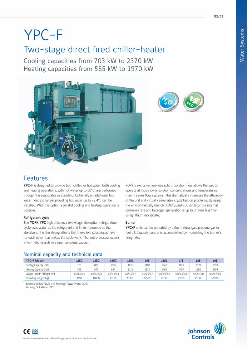
YPC-FTwo-stage direct fired chiller-heaterCooling capacities from 703 kW to 2370 kWHeating capacities from 565 kW to 1970 kW
FeaturesYPC-F is designed to provide both chilled or hot water. Both cooling and heating operations, with hot water up to 60°C, are performed through the evaporator as standard. Optionally an additional hot water heat exchanger providing hot water up to 79,4°C can be installed. With this option a parallel cooling and heating operation is possible.
Refrigerant cycleThe YORK YPC high efficiency two-stage absorption refrigeration cycle uses water as the refrigerant and lithium bromide as the absorbent. It is the strong affinity that these two substances have for each other that makes the cycle work. The entire process occurs in hermetic vessels in a near complete vacuum.
YORK’s exclusive two-way split of solution flow allows the unit to operate at much lower solution concentrations and temperatures than in series flow systems. This dramatically increases the efficiency of the unit and virtually eliminates crystallisation problems. By using the environmentally friendly ADVAGuard 750 inhibitor the internal corrosion rate and hydrogen generation is up to 8 times less than using lithium molybdate.
BurnerYPC-F units can be operated by either natural gas, propane gas or fuel oil. Capacity control is accomplished by modulating the burner’s firing rate.
Nominal capacity and technical dataYPC-F Model 12SC 13SC 14SC 15SL 16S 16SL 17S 18S 19S
Cooling Capacity (kW) 703 809 1055 1231 1407 1547 1705 2039 2373
Heating Capacity (kW) 563 675 844 1013 1125 1268 1407 1688 1969
Length / Width / Height (m) 4.0/1.9/2.3 4.0/2.0/2.3 5.0/1.9/2.3 5.0/2.5/2.7 5.0/2.5/2.7 6.0/2.6/2.8 6.0/2.6/2.8 7.0/2.7/3.0 8.0/2.7/3.0
Operating weight (kg) 9490 10830 12130 17360 17580 21180 21580 25190 29720
Leaving chilled liquid 7°C Entering Tower Water 30°C.Leaving Hot Water 60°C.

york air-conditioning products
Central Plant OptimizationTM 10A facility’s central chiller plant typically uses 20% of the building’s total energy. Managing this load, while still maintaining occupant comfort, is a primary strategy for overall energy management.
Johnson Controls® Central Plant Optimization™ 10 (CPO 10) provides such a strategy combining expertise from designing YORK® chillers and Metasys® controls to save energy and improve reliability in the facility.
The application uses tested best practices to select the most efficient combination of chillers, pumps and cooling towers to match the building load. It then commands the selected devices providing the necessary sequencing of pumps, isolation valves and main equipment, while observing safety and stability operation requirements.

Manufacturer reserves the rights to change specifications without prior notice.
Wat
er S
yste
ms
54/55
Creating a complex program without programmingThe System Selection Tool (SST) is a control program generator that relies on defining the characteristics of the chiller plant and its control strategies. The tool supports selection and sequencing of
• up to eight chillers of different sizes
• up to eight (each) primary and secondary chilled water pumps of varying pumping capacities
• up to eight condenser water pumps
• cooling towers and bypass valve, including single speed, multi-speed, and vernier control
• devices that considers user-defined efficiency rating, runtime equalization, and the number-of-starts/number-of-stops equalization
Furthermore, control definition for the chiller plant in a single Field Equipment Controller (FEC)/Network Controller Engine (NCE), if supported by available memory and point Input/Output (I/O), or split across multiple FECs/NCEs, is offered.
Flexibility, ready for use
A variety of primary control strategies are also available, including
• measuring building chilled-water flow and differential temperature
• chillers’ kW load flow through a decoupler pipe in a primary/secondary system differential temperature only in a constant speed chilled water pump system
It is also possible to select dozens of secondary strategies, such as
• open loop control of the cooling towers (as defined by the American Society of Heating, Refrigerating and Air-Conditioning Engineers)
• closed loop control of condenser-water setpoint
After making the selections, SST generates a complete program by linking together appropriate software modules. This process removes the variability commonly found in totally custom-generated programs using a traditional software program editor.
Once the software modules are linked, the tool allows the entry of all equipment parameters. The resulting program can also be run in a simulator mode to verify proper operation before downloading it into Metasys®.

york air-conditioning products

custom & “hygienic” air handling units
fan coil units
close control units
smartpac - factory packaged controls
Air Handling Systems& Terminal Devices
56/57

york air-conditioning products
So why choose YORK® Air Handling Units?
Energy recovery options
The exhaust air stream from an AHU represents another opportunity to save energy. A heat recovery ‘thermal’ wheel can economically transfer heat and moisture between the exhaust-air and outside-air paths, reducing the cost of conditioning the supply air.
For the simplest form of heat recovery, you can take advantage of “free” cooling with mixing box sections. During spring and autumn operation, cool/dry outside air cools and dehumidifies the facility, reducing the need for mechanical cooling.
Alternatively, you can use recuperative plate heat exchangers. These also allow free cooling in summer by use of face and bypass dampers which by-pass the air around the exchanger so that it is not warmed by the extracted air.
We can also offer refrigerant heat pipe and heat recovery coils on your AHU to maximise energy savings.
Reduce fan operating costs
In an AHU, the fan is traditionally the largest source of energy consumption. We can help reduce this by offering a range of energy-saving options.
• High- or premium-efficiency motors can be specified.
• Direct-drive plenum fans eliminate belt-and-pulley energy losses.
• If the air system is designed for variable-air volume (VAV), YORK® AHUs fitted with variable speed drives offer the most efficient method of VAV fan control.
• Factory-mounting a variable speed drive reduce jobsite labour costs, unit energy consumption and unit Life Cycle Costs.
We recognise that your reputation depends on the quality of the products you choose and how well they are installed. That’s why we work hard to make selecting, installing and operating our products as easy as possible. Our YMA range includes a number of additional options that make YORK® Air Handling Units the professionals’ choice.
Factory Packaged Controls option
• AHUs Metasys® factory packaged controls specified option available.
• Panel Power wiring, Controls wiring and the Variable Speed Drive are included. The pre-engineered controller and required peripheral devices are all supplied factory fitted and tested.
• Guaranteed compliance with European installation regulations.
• Simplified final commissioning through the units’ keypad and display.
Heat-recovery wheels reduce the cost of conditioning supply air.
Factory Packaged controls
Save money and time avoiding to mount controls on-site. Johnson Controls offers YORK® Air Handling Units complete with Metasys® factory packaged controls so it is ready connect to the site network when it arrives.
Our Factory Packaged controls undergo a detailed testing process at the factory to ensure that all wiring is installed correctly, and that all control panels and end devices work appropriately before the AHU is shipped.

58/59
Air
Han
dlin
g Sy
stem
s &
Ter
min
al D
evic
esIntroducing the YMA range of Air Handling Units
Over the past 50 years we have supplied air handling units for:
• Commercial space: office buildings, cinemas, concert halls
• Institutional space: schools, universities, churches
• Industrial manufacturing: automotive, aerospace, chemical, petrochemical
• Hygienic systems: hospitals, life sciences, R&D facilities, food processing, clean rooms
• Process manufacturing: pharmaceutical, electronics, semiconductor
FeaturesThe YMA family of air handling units consists of a range of models having air volumes ranging from 0.25 m3/s to 50 m3/s and total static pressures as high as 2000 Pascal: to ensure maximum flexibility and the best solution for your application, units are available in increments of 40mm in height and 50mm in width.
YMA Air Handling Units can be manufactured in varied configurations, with a wide selection of components, to meet customer requirements. Units are also available in line with the requirements of hospital sector specifications.
Dimensional flexibility. Space constraints are a reality on most construction projects. YORK® AHU’s design is based on variable aspect ratios, so the unit can be specified to fit the application and space.
Material flexibility. Different environments require different materials so we offer a number of construction materials, including galvanized steel, pre-coated steel, stainless steel, and aluminium.
Component flexibility. To meet any AHU requirement, our units offer every available air-handling component. And as applicable technology creates new capabilities, Johnson Controls will apply this to our product range.
The YORK® by Johnson Controls YMA range encompasses our extensive knowledge of air-handling, offering a highly reliable, economical and energy efficient product capable of addressing all of your needs.
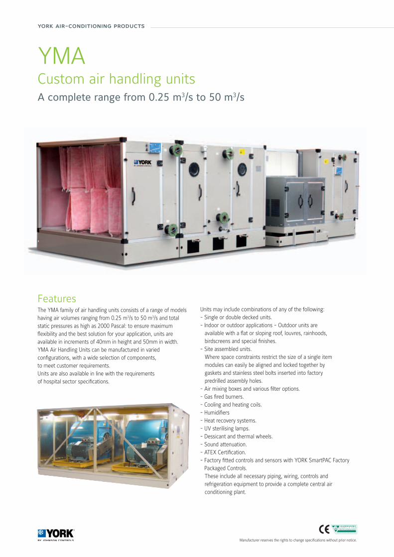
york air-conditioning products
YMACustom air handling unitsA complete range from 0.25 m3/s to 50 m3/s
FeaturesThe YMA family of air handling units consists of a range of models having air volumes ranging from 0.25 m3/s to 50 m3/s and total static pressures as high as 2000 Pascal: to ensure maximum flexibility and the best solution for your application, units are available in increments of 40mm in height and 50mm in width.YMA Air Handling Units can be manufactured in variedconfigurations, with a wide selection of components,to meet customer requirements. Units are also available in line with the requirementsof hospital sector specifications.
Units may include combinations of any of the following:- Single or double decked units.- Indoor or outdoor applications - Outdoor units are available with a flat or sloping roof, louvres, rainhoods, birdscreens and special finishes.- Site assembled units. Where space constraints restrict the size of a single item modules can easily be aligned and locked together by gaskets and stainless steel bolts inserted into factory predrilled assembly holes.- Air mixing boxes and various filter options.- Gas fired burners.- Cooling and heating coils.- Humidifiers- Heat recovery systems.- UV sterilising lamps.- Dessicant and thermal wheels.- Sound attenuation.- ATEX Certification.- Factory fitted controls and sensors with YORK SmartPAC Factory
Packaged Controls. These include all necessary piping, wiring, controls and
refrigeration equipment to provide a complete central air conditioning plant.
Manufacturer reserves the rights to change specifications without prior notice.
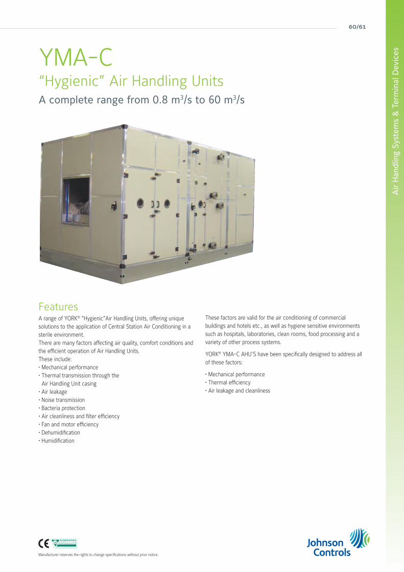
60/61
Air
Han
dlin
g Sy
stem
s &
Ter
min
al D
evic
es
Manufacturer reserves the rights to change specifications without prior notice.
YMA-C“Hygienic” Air Handling UnitsA complete range from 0.8 m3/s to 60 m3/s
FeaturesA range of YORK® “Hygienic”Air Handling Units, offering unique solutions to the application of Central Station Air Conditioning in a sterile environment.There are many factors affecting air quality, comfort conditions and the efficient operation of Air Handling Units.These include:• Mechanical performance• Thermal transmission through the Air Handling Unit casing• Air leakage• Noise transmission • Bacteria protection• Air cleanliness and filter efficiency• Fan and motor efficiency• Dehumidification• Humidification
These factors are valid for the air conditioning of commercial buildings and hotels etc., as well as hygiene sensitive environments such as hospitals, laboratories, clean rooms, food processing and a variety of other process systems.
YORK® YMA-C AHU’S have been specifically designed to address all of these factors:
• Mechanical performance• Thermal efficiency• Air leakage and cleanliness

york air-conditioning products
YORK® Fan Coil unitsDriven by innovative trends and modern technology, the YORK® Fan Coil Units have been designed around a platform of models, versions and accessories, which have been independently tested and certified by Eurovent. The YORK® Fan Coil range meets today’s demanding requirements of performance, size, acoustics, low energy, ease of installation and maintenance.

62/63
Air
Han
dlin
g Sy
stem
s &
Ter
min
al D
evic
es
Manufacturer reserves the rights to change specifications without prior notice.
An extensive offering • One of the most versatile ranges of fan coils on the market today. Wall and ceiling mounted units, exposed or concealed with centrifugal fan, are included, and with cooling capacities ranging from 0.6 kW to 14 kW.
• Dramatic electrical consumption reduction of up to 40% comparative to previous models. This is achieved thanks to the supply of all YORK® Fan Coil Units equipped with centrifugal fans and electric motors, and with 6 speed motors as standard to offer greater flexibility in the selection of products.
• Energy saving brushless motor technology option available. Its combination with a dedicated frequency inverter and unit controller to regulate the fan speed enables higher efficiencies, even at low rotational speeds, lower unit noise, constant speed characteristics and an increase in motor lifetime expectancy. In comparison to the traditional units equipped with asynchronous three-speed-motors, units with brushless motors can obtain a considerable energy saving, by reducing the power consumption by up to 70%.
• A full range of factory fitted Johnson Controls valve and pre-configured control options is offered. This in addition to a patented ‘wireless’ control option - offering greater flexibility in the installation of units, with the highest precision in monitoring and maintaining the desired comfort conditions.
• High pressure ‘Blower’ units are also available. They can offer up to 23kw of cooling at External Static Pressures of up to 250Pa, and are complemented with a full range of options and accessories covering items such as electrical heating battery, air inlet/outlet diffusers and condensate pumps.
Iconography
Infrared or Wired control
Dry modeWiredcontrol
Sleepmode
Timer AutoSweep
AutoRestart
4 WayAir Flow
DuctedInstallation
Air Filter
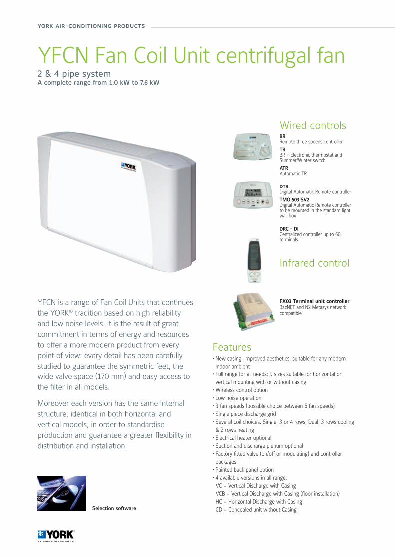
york air-conditioning products
YFCN Fan Coil Unit centrifugal fan2 & 4 pipe systemA complete range from 1.0 kW to 7.6 kW
Features• New casing, improved aesthetics, suitable for any modern indoor ambient
• Full range for all needs: 9 sizes suitable for horizontal or vertical mounting with or without casing
• Wireless control option• Low noise operation • 3 fan speeds (possible choice between 6 fan speeds)• Single piece discharge grid • Several coil choices. Single: 3 or 4 rows; Dual: 3 rows cooling & 2 rows heating
• Electrical heater optional • Suction and discharge plenum optional • Factory fitted valve (on/off or modulating) and controller packages
• Painted back panel option • 4 available versions in all range: VC = Vertical Discharge with Casing VCB = Vertical Discharge with Casing (floor installation) HC = Horizontal Discharge with Casing CD = Concealed unit without Casing
YFCN is a range of Fan Coil Units that continues the YORK® tradition based on high reliability and low noise levels. It is the result of great commitment in terms of energy and resources to offer a more modern product from every point of view: every detail has been carefully studied to guarantee the symmetric feet, the wide valve space (170 mm) and easy access to the filter in all models.
Moreover each version has the same internal structure, identical in both horizontal and vertical models, in order to standardise production and guarantee a greater flexibility in distribution and installation.
Selection software
Wired controlsBRRemote three speeds controller
TRBR + Electronic thermostat and Summer/Winter switch
ATRAutomatic TR
DTRDigital Automatic Remote controller
TMO 503 SV2Digital Automatic Remote controllerto be mounted in the standard light wall box
DRC - DICentralized controller up to 60 terminals
Infrared control
FX03 Terminal unit controllerBacNET and N2 Metasys network compatible

64/65
Air
Han
dlin
g Sy
stem
s &
Ter
min
al D
evic
es
Manufacturer reserves the rights to change specifications without prior notice.
YFCN Fan Coil Unit centrifugal fan1.0 to 7.6 kW
Technical featuresModel 140 240 340 440 540 640 740 840 940
Total cooling capacity [kW] (1)
max 1.23 1.81 2.57 3.12 4.1 4.8 5.58 6.47 7.6
med 1.02 1.43 1.89 2.28 3.25 3.86 4.64 5.73 6.54
min 0.67 1.01 1.65 1.83 2.2 2.83 3.56 4.03 4.88
Sensible cooling capacity [kW] (1)
max 0.97 1.38 1.9 2.34 2.07 3.6 4.23 5.06 6.05
med 0.79 1.07 1.38 1.68 2.4 2.86 3.47 4.43 5.11
min 0.51 0.74 1.2 1.34 1.6 2.07 2.62 3.04 3.72
Water flow in cooling [l/h] (1)
max 229 335 475 576 757 884 1032 1201 1410
med 189 265 349 421 600 714 857 1061 1213
min 126 186 304 339 404 523 657 746 903
Pressure drop in cooling [kPa] (1)
max 5.6 13.9 11.5 15.5 31.3 36.2 27.7 17.5 23.2
med 4 9.2 6.7 9 20.8 24.8 20 14.1 17.8
min 1.9 4.9 5.3 6.1 10.4 14.4 12.5 7.6 10.6
Heating capacity 2 pipes [kW] (2)
max 1.6 2.25 3.14 3.87 4.93 6.05 6.88 8.77 10.53
med 1.32 1.76 2.28 2.79 3.89 4.8 5.68 7.65 8.87
min 0.84 1.21 1.98 2.21 2.58 3.46 4.29 5.23 6.44
Water flow in heating 2 pipes [l/h] * (2)
max 275 387 540 666 848 1041 1183 1508 1811
med 227 303 392 480 669 826 977 1316 1526
min 144 208 341 380 444 595 738 900 1108
Pressure drop in heating 2 pipes [kPa] (2)
max 7.3 16.7 13.2 18.1 35.7 44.9 32.8 24.5 33.8
med 5.2 10.8 7.5 10.2 23.5 29.9 23.5 19.3 25
min 2.4 5.6 5.8 6.8 11.4 16.8 14.3 9.9 14.3
Air flow [m3/h]
max 220 295 385 485 650 760 925 1200 1500
med 175 220 270 335 495 590 735 1020 1210
min 105 145 235 265 315 415 535 655 830
Sound power level [dB(A)]
max 45 47 49 47 48 52 56 60 64
med 39 40 40 39 41 46 51 56 58
min 32 30 36 33 31 37 42 45 50
Sound pressure level [dB(A)] (3)
max 36 38 40 38 39 43 47 51 55
med 30 31 31 30 32 37 42 47 49
min 23 21 27 24 22 28 33 36 41
Power supply [V-ph-Hz] 230 / 1 / 50 + E
Power input [W] max 33 40 49 57 61 88 103 130 176
Absorbed current [A] max 0.16 0.18 0.23 0.26 0.27 0.39 0.47 0.58 0.78
Dimensions
Height mm 530 530 530 530 530 530 530 530 530
Width mm 670 770 985 985 1200 1200 1415 1415 1415
Depth mm 225 225 225 225 225 225 225 255 255
(1) Room temperature 27°C d.b., 19°C w.b. - Water temperature 7/12 °C(2) Room temperature 20°C - Water inlet temperature: 50°C(3) Sound pressure level in a 100 m2 room, at 1,5 m distance and riverberating time of 0,5 s.* Water flow values as Cooling, accordingly to the EUROVENT standards and UNI ENV 1397Data shown is for 4 row cooling version, 2 pipe system. For performance of 3 row cooling version and/or 4 pipe system unit please contact your local Johnson Controls sales office
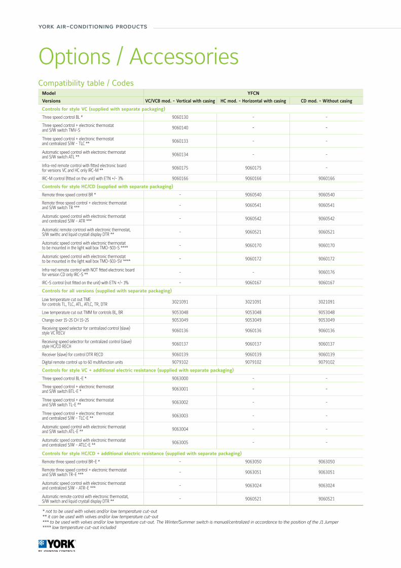
york air-conditioning products
Compatibility table / CodesModel YFCN
Versions VC/VCB mod. - Vertical with casing HC mod. - Horizontal with casing CD mod. - Without casing
Controls for style VC (supplied with separate packaging)
Three speed control BL * 9060130 - -
Three speed control + electronic thermostat and S/W switch TMV-S 9060140 - -
Three speed control + electronic thermostat and centralized S/W - TLC ** 9060133 - -
Automatic speed control with electronic thermostat and S/W switch ATL ** 9060134 - -
Infra-red remote control with fitted electronic board for versions VC and HC only IRC-M ** 9060175 9060175 -
IRC-M control (fitted on the unit) with ETN +/- 3% 9060166 9060166 9060166
Controls for style HC/CD (supplied with separate packaging)
Remote three speed control BR * - 9060540 9060540
Remote three speed control + electronic thermostat and S/W switch TR *** - 9060541 9060541
Automatic speed control with electronic thermostat and centralized S/W - ATR *** - 9060542 9060542
Automatic remote controol with electronic thermostat, S/W swithc and liquid crystall display DTR ** - 9060521 9060521
Automatic speed control with electronic thermostat to be mounted in the light wall box TMO-503-S **** - 9060170 9060170
Automatic speed control with electronic thermostat to be mounted in the light wall box TMO-503-SV **** - 9060172 9060172
Infra-red remote control with NOT fitted electronic board for version CD only IRC-S ** - - 9060176
IRC-S control (not fitted on the unit) with ETN +/- 3% - 9060167 9060167
Controls for all versions (supplied with separate packaging)
Low temperature cut out TME for controls TL, TLC, ATL, ATLC, TR, DTR 3021091 3021091 3021091
Low temperature cut out TMM for controls BL, BR 9053048 9053048 9053048
Change over 15-25 CH 15-25 9053049 9053049 9053049
Receiving speed selector for centralized control (slave) style VC RECV 9060136 9060136 9060136
Receiving speed selectror for centralized control (slave) style HC/CD RECH 9060137 9060137 9060137
Receiver (slave) for control DTR RECD 9060139 9060139 9060139
Digital remote control up to 60 multifunction units 9079102 9079102 9079102
Controls for style VC + additional electric resistance (supplied with separate packaging)
Three speed control BL-E * 9063000 - -
Three speed control + electronic thermostat and S/W switch BTL-E * 9063001 - -
Three speed control + electronic thermostat and S/W switch TL-E ** 9063002 - -
Three speed control + electronic thermostat and centralized S/W - TLC-E ** 9063003 - -
Automatic speed control with electronic thermostat and S/W switch ATL-E ** 9063004 - -
Automatic speed control with electronic thermostat and centralized S/W - ATLC-E ** 9063005 - -
Controls for style HC/CD + additional electric resistance (supplied with separate packaging)
Remote three speed control BR-E * - 9063050 9063050
Remote three speed control + electronic thermostat and S/W switch TR-E *** - 9063051 9063051
Automatic speed control with electronic thermostat and centralized S/W - ATR-E *** - 9063024 9063024
Automatic remote control with electronic thermostat, S/W switch and liquid crystall display DTR ** - 9060521 9060521
* not to be used with valves and/or low temperature cut-out** it can be used with valves and/or low temperature cut-out*** to be used with valves and/or low temperature cut-out. The Winter/Summer switch is manual/centralized in accordance to the position of the J1 Jumper**** low temperature cut-out included
Options / Accessories
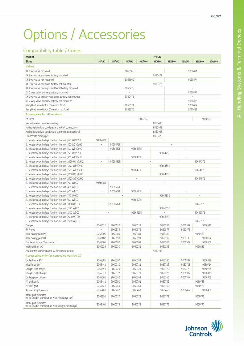
66/67
Air
Han
dlin
g Sy
stem
s &
Ter
min
al D
evic
esOptions / AccessoriesCompatibility table / Codes
Model YFCN
Sizes 130/140 230/240 330/340 430/440 530/540 630/640 730/740 830/840 930/940
Valves
Kit 3 way valve mounted 9066561 9060471
Kit 3 way valve additional battery mounted 9060472
Kit 3 way valve not mounted 9066560 9060474
Kit 3 way valve additional battery not mounted 9060475
Kit 2 way valve primary + additional battery mounted 9060476 -
Kit 2 way valve primary battery mounted - 9060477
Kit 2 way valve primary+additional battery not mounted 9060478 -
Kit 2 way valve primary battery not mounted - 9060479
Semplified valve kit for CD version fitted 9066571 9060484
Semplified valve kit for CD version not fitted 9066570 9060481
Accessories for all versions
Pair feet 9060150 9060151
Vertical auxiliary condensate tray 6060400
Horizontal auxiliary condensate tray (left connections) 6060402
Horizontal auxiliary condensate tray (right connections) 6060403
Condensate drain pipe 6060420
El. resistance and relays fitted on the unit (650 W) VC/HC 9066491E -
El. resistance and relays fitted on the unit (400 W) VC/HC - 9066472E -
El. resistance and relays fitted on the unit (600 W) VC/HC - 9066482E 9066473E -
El. resistance and relays fitted on the unit (750 W) VC/HC - 9066475E -
El. resistance and relays fitted on the unit (900 W) VC/HC - 9066483E -
El. resistance and relays fitted on the unit (1000 W) VC/HC - 9066492E - 9066477E
El. resistance and relays fitted on the unit (1250 W) VC/HC - 9066485E -
El. resistance and relays fitted on the unit (1500 W) VC/HC - 9066493E - 9066487E
El. resistance and relays fitted on the unit (2000 W) VC/HC - 9066495E -
El. resistance and relays fitted on the unit (2500 W) VC/HC - 9066497E
El. resistance and relays fitted on the unit (700 W) CD 9066611E -
El. resistance and relays fitted on the unit (400 W) CD - 9066592E -
El. resistance and relays fitted on the unit (600 W) CD - 9066602E 9066593E -
El. resistance and relays fitted on the unit (750 W) CD - 9066595E -
El. resistance and relays fitted on the unit (900 W) CD - 9066603E -
El. resistance and relays fitted on the unit (1000 W) CD - 9066612E - 9066597E
El. resistance and relays fitted on the unit (1250 W) CD - 9066605E -
El. resistance and relays fitted on the unit (1500 W) CD - 9066613E - 9066607E
El. resistance and relays fitted on the unit (2000 W) CD - 9066615E -
El. resistance and relays fitted on the unit (2500 W) CD - 9066617E
Damper 9066531 9066532 9066533 9066535 9066537 9066538
IM Frame - 9060575 9060576 9060577 9060578 -
Rear closing panel VC 9062005 9060180 9060181 9060182 9060183
Rear closing panel HC 9060187 9060190 9060191 9060192 9060193 9060194
Frontal air intake CD mounted 9066501 9066502 9066503 9066505 9066507 9066508
Intake grid for VC 9060229 9060230 9060231 9060232 9060233
Adaptor for terminal board VC for remote control 9060103
Accessories only for concealed version CD
Outlet flange 90° 9066381 9066382 9066383 9066385 9066387 9066388
Inlet flange 90° 9066441 9060710 9060711 9060712 9060713 9060714
Straight inlet flange 9066451 9060720 9060721 9060722 9060723 9060724
Straight outlet flange 9066371 9066372 9066373 9066375 9066377 9066378
Outlet spigot diffuser 9066361 9066362 9066363 9066365 9066367 9066368
Air outlet grid 9066411 9060750 9060751 9060752 9060753
Air inlet grid 9066421 9060760 9060761 9060762 9060763
Air inlet spigot plenum 9066461 9066462 9066463 9066465 9066467 9066468
Intake grid with filter (to be used in combination with inlet flange 90°) 9066391 9060770 9060771 9060772 9060773
Intake grid with filter (to be used in combination with straight inlet flange) 9066401 9060774 9060775 9060776 9060777
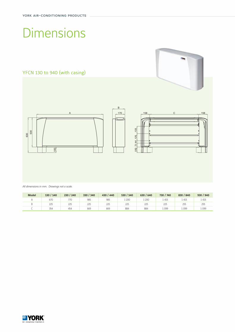
york air-conditioning products
All dimensions in mm. Drawings not a scale.
YFCN 130 to 940 (with casing)
Dimensions
Model 130 / 140 230 / 240 330 / 340 430 / 440 530 / 540 630 / 640 730 / 740 830 / 840 930 / 940
A 670 770 985 985 1 200 1 200 1 415 1 415 1 415
B 225 225 225 225 225 225 225 255 255
C 354 454 669 669 884 884 1 099 1 099 1 099
B
170 158 158
7144
125
133
C
001
A
001
530
630

68/69
Air
Han
dlin
g Sy
stem
s &
Ter
min
al D
evic
es
All dimensions in mm. Drawings not a scale.
YFCN 130 to 940 (without casing)
Dimensions
B
153
511
A
22 22
29
12 12
7144
125
133
10 C
153
17
119
A
12 12
153 B
511
Model 130 / 140 230 / 240 330 / 340 430 / 440 530 / 540 630 / 640 730 / 740 830 / 840 930 / 940
A 374 474 689 689 904 904 1 119 1 119 1 119
B 218 218 218 218 218 218 218 248 248
C 354 454 669 669 884 884 1 099 1 099 1 099
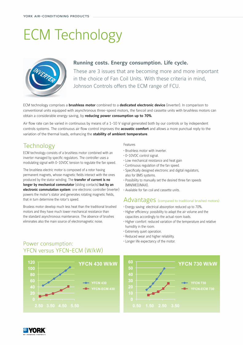
york air-conditioning products
ECM Technology
Advantages (compared to traditional brushed motors)
• Energy saving: electrical absorption reduced up to 70%.• Higher efficiency: possibility to adapt the air volume and the capacities accordingly to the actual room loads.
• Higher comfort: reduced variation of the temperature and relative humidity in the room.
• Extremely quiet operation.• Reduced wear and higher reliability.• Longer life expectancy of the motor.
Features
• Brushless motor with inverter.• 0-10VDC control signal.• Low mechanical resistance and heat gain• Continuous regulation of the fan speed.• Specifically designed electronic and digital regulators, also for BMS systems.
• Possibility to manually set the desired three fan speeds (MIN/MED/MAX).
• Available for fan coil and cassette units.
Running costs. Energy consumption. Life cycle.
These are 3 issues that are becoming more and more important in the choice of Fan Coil Units. With these criteria in mind, Johnson Controls offers the ECM range of FCU.
ECM technology comprises a brushless motor combined to a dedicated electronic device (inverter). In comparison to
conventional units equipped with asynchronous three-speed motors, the fancoil and cassette units with brushless motors can
obtain a considerable energy saving, by reducing power consumption up to 70%.
Air flow rate can be varied in continuous by means of a 1-10 V signal generated both by our controls or by independent
controls systems. The continuous air flow control improves the acoustic comfort and allows a more punctual reply to the
variation of the thermal loads, enhancing the stability of ambient temperature.
TechnologyECM technology consists of a brushless motor combined with an inverter managed by specific regulators. The controller uses a modulating signal with 0-10VDC tension to regulate the fan speed.
The brushless electric motor is composed of a rotor having permanent magnets, whose magnetic fields interact with the ones produced by the stator winding. The transfer of current is no longer by mechanical commutator (sliding contacts) but by an electronic commutation system: one electronic controller (inverter) powers the motor’s stator and generates rotating magnetic fields, that in turn determine the rotor’s speed.
Brusless motor develop much less heat than the traditional brushed motors and they have much lower mechanical resistance than the standard asynchronous maintenance. The absence of brushes eliminates also the main source of electromagnetic noise.
Power consumption:YFCN versus YFCN-ECM (W/kW)
YFCN 430
YFCN-ECM 430
YFCN 730
YFCN-ECM 730
YFCN 430 W/kW YFCN 730 W/kW
0.502.50 1.503.50 2.504.50 3.505.50
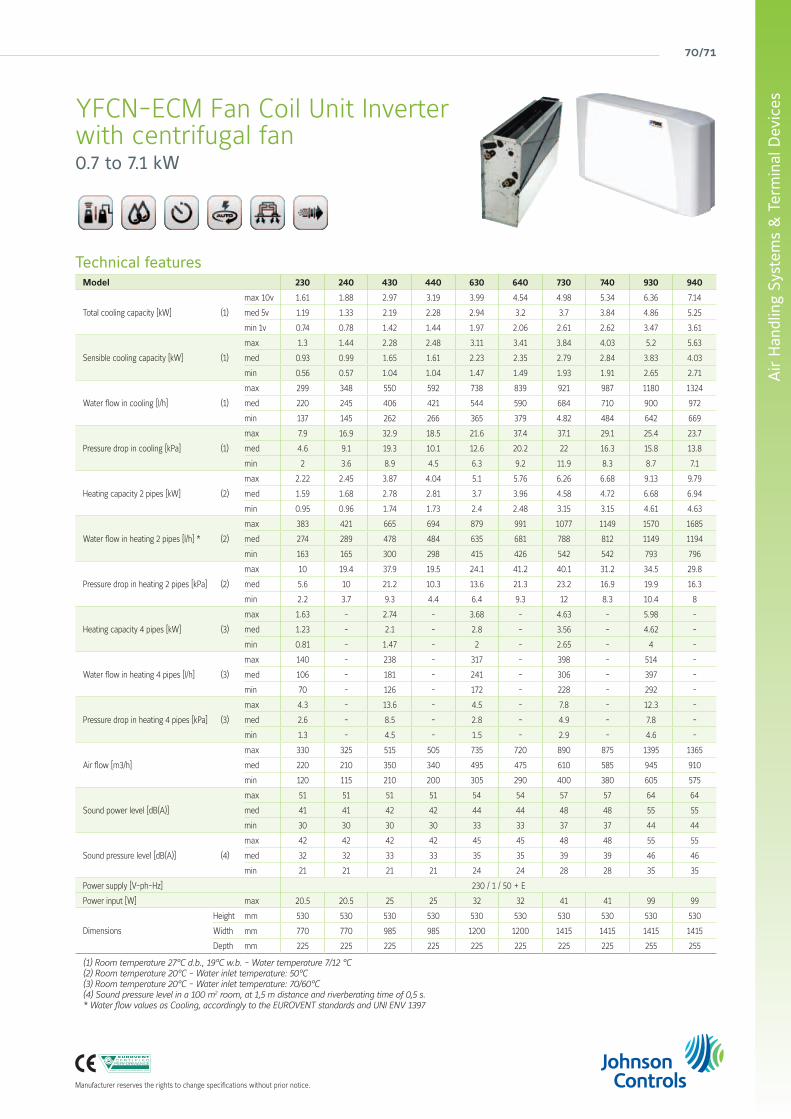
70/71
Air
Han
dlin
g Sy
stem
s &
Ter
min
al D
evic
es
Manufacturer reserves the rights to change specifications without prior notice.
YFCN-ECM Fan Coil Unit Inverterwith centrifugal fan0.7 to 7.1 kW
Technical featuresModel 230 240 430 440 630 640 730 740 930 940
Total cooling capacity [kW] (1)
max 10v 1.61 1.88 2.97 3.19 3.99 4.54 4.98 5.34 6.36 7.14
med 5v 1.19 1.33 2.19 2.28 2.94 3.2 3.7 3.84 4.86 5.25
min 1v 0.74 0.78 1.42 1.44 1.97 2.06 2.61 2.62 3.47 3.61
Sensible cooling capacity [kW] (1)
max 1.3 1.44 2.28 2.48 3.11 3.41 3.84 4.03 5.2 5.63
med 0.93 0.99 1.65 1.61 2.23 2.35 2.79 2.84 3.83 4.03
min 0.56 0.57 1.04 1.04 1.47 1.49 1.93 1.91 2.65 2.71
Water flow in cooling [l/h] (1)
max 299 348 550 592 738 839 921 987 1180 1324
med 220 245 406 421 544 590 684 710 900 972
min 137 145 262 266 365 379 4.82 484 642 669
Pressure drop in cooling [kPa] (1)
max 7.9 16.9 32.9 18.5 21.6 37.4 37.1 29.1 25.4 23.7
med 4.6 9.1 19.3 10.1 12.6 20.2 22 16.3 15.8 13.8
min 2 3.6 8.9 4.5 6.3 9.2 11.9 8.3 8.7 7.1
Heating capacity 2 pipes [kW] (2)
max 2.22 2.45 3.87 4.04 5.1 5.76 6.26 6.68 9.13 9.79
med 1.59 1.68 2.78 2.81 3.7 3.96 4.58 4.72 6.68 6.94
min 0.95 0.96 1.74 1.73 2.4 2.48 3.15 3.15 4.61 4.63
Water flow in heating 2 pipes [l/h] * (2)
max 383 421 665 694 879 991 1077 1149 1570 1685
med 274 289 478 484 635 681 788 812 1149 1194
min 163 165 300 298 415 426 542 542 793 796
Pressure drop in heating 2 pipes [kPa] (2)
max 10 19.4 37.9 19.5 24.1 41.2 40.1 31.2 34.5 29.8
med 5.6 10 21.2 10.3 13.6 21.3 23.2 16.9 19.9 16.3
min 2.2 3.7 9.3 4.4 6.4 9.3 12 8.3 10.4 8
Heating capacity 4 pipes [kW] (3)
max 1.63 - 2.74 - 3.68 - 4.63 - 5.98 -
med 1.23 - 2.1 - 2.8 - 3.56 - 4.62 -
min 0.81 - 1.47 - 2 - 2.65 - 4 -
Water flow in heating 4 pipes [l/h] (3)
max 140 - 238 - 317 - 398 - 514 -
med 106 - 181 - 241 - 306 - 397 -
min 70 - 126 - 172 - 228 - 292 -
Pressure drop in heating 4 pipes [kPa] (3)
max 4.3 - 13.6 - 4.5 - 7.8 - 12.3 -
med 2.6 - 8.5 - 2.8 - 4.9 - 7.8 -
min 1.3 - 4.5 - 1.5 - 2.9 - 4.6 -
Air flow [m3/h]
max 330 325 515 505 735 720 890 875 1395 1365
med 220 210 350 340 495 475 610 585 945 910
min 120 115 210 200 305 290 400 380 605 575
Sound power level [dB(A)]
max 51 51 51 51 54 54 57 57 64 64
med 41 41 42 42 44 44 48 48 55 55
min 30 30 30 30 33 33 37 37 44 44
Sound pressure level [dB(A)] (4)
max 42 42 42 42 45 45 48 48 55 55
med 32 32 33 33 35 35 39 39 46 46
min 21 21 21 21 24 24 28 28 35 35
Power supply [V-ph-Hz] 230 / 1 / 50 + E
Power input [W] max 20.5 20.5 25 25 32 32 41 41 99 99
Dimensions
Height mm 530 530 530 530 530 530 530 530 530 530
Width mm 770 770 985 985 1200 1200 1415 1415 1415 1415
Depth mm 225 225 225 225 225 225 225 225 255 255
(1) Room temperature 27°C d.b., 19°C w.b. - Water temperature 7/12 °C(2) Room temperature 20°C - Water inlet temperature: 50°C(3) Room temperature 20°C - Water inlet temperature: 70/60°C(4) Sound pressure level in a 100 m2 room, at 1,5 m distance and riverberating time of 0,5 s.* Water flow values as Cooling, accordingly to the EUROVENT standards and UNI ENV 1397
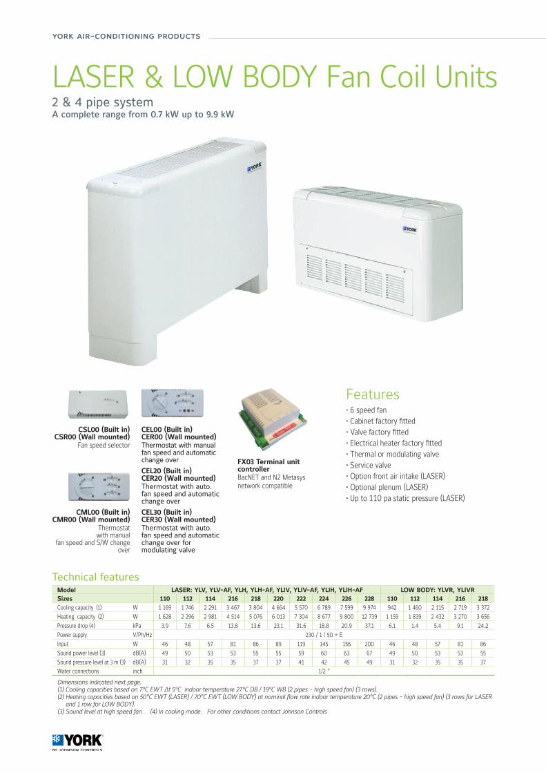
york air-conditioning products
Technical featuresModel LASER: YLV, YLV-AF, YLH, YLH-AF, YLIV, YLIV-AF, YLIH, YLIH-AF LOW BODY: YLVR, YLIVRSizes 110 112 114 216 218 220 222 224 226 228 110 112 114 216 218Cooling capacity (1) W 1 169 1 746 2 291 3 467 3 804 4 664 5 570 6 789 7 599 9 974 942 1 460 2 115 2 719 3 372
Heating capacity (2) W 1 628 2 296 2 981 4 514 5 076 6 013 7 304 8 677 9 800 12 739 1 159 1 839 2 432 3 270 3 656
Pressure drop (4) kPa 3.9 7.6 6.5 13.8 13.6 23.1 31.6 18.8 20.9 37.1 6.1 1.4 5.4 9.1 24.2
Power supply V/Ph/Hz 230 / 1 / 50 + E
Input W 46 48 57 81 86 89 119 145 156 200 46 48 57 81 86
Sound power level (3) dB(A) 49 50 53 53 55 55 59 60 63 67 49 50 53 53 55
Sound pressure level at 3 m (3) dB(A) 31 32 35 35 37 37 41 42 45 49 31 32 35 35 37Water connections inch 1/2 “
Dimensions indicated next page. (1) Cooling capacities based on 7°C EWT ∆t 5°C indoor temperature 27°C DB / 19°C WB (2 pipes - high speed fan) (3 rows).(2) Heating capacities based on 50°C EWT (LASER) / 70°C EWT (LOW BODY) at nominal flow rate indoor temperature 20°C (2 pipes - high speed fan) (3 rows for LASER
and 1 row for LOW BODY). (3) Sound level at high speed fan . (4) In cooling mode. For other conditions contact Johnson Controls
LASER & LOW BODY Fan Coil Units2 & 4 pipe systemA complete range from 0.7 kW up to 9.9 kW
CSL00 (Built in)CSR00 (Wall mounted)
Fan speed selector
CML00 (Built in)CMR00 (Wall mounted)
Thermostatwith manual
fan speed and S/W change over
CEL00 (Built in)CER00 (Wall mounted)Thermostat with manual fan speed and automatic change over
CEL20 (Built in)CER20 (Wall mounted)Thermostat with auto. fan speed and automatic change over
CEL30 (Built in)CER30 (Wall mounted)Thermostat with auto. fan speed and automatic change over for modulating valve
FX03 Terminal unit controllerBacNET and N2 Metasys network compatible
Features• 6 speed fan• Cabinet factory fitted• Valve factory fitted• Electrical heater factory fitted• Thermal or modulating valve• Service valve• Option front air intake (LASER)• Optional plenum (LASER)• Up to 110 pa static pressure (LASER)
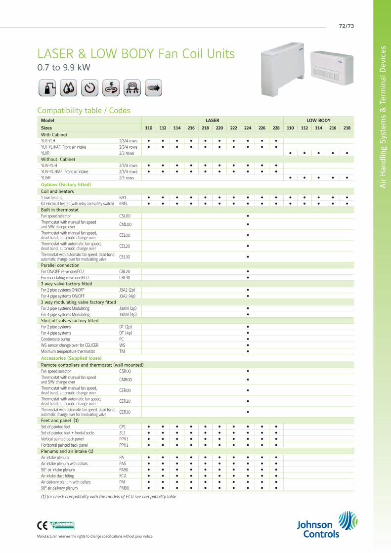
72/73
Air
Han
dlin
g Sy
stem
s &
Ter
min
al D
evic
es
Manufacturer reserves the rights to change specifications without prior notice.
Compatibility table / CodesModel LASER LOW BODY
Sizes 110 112 114 216 218 220 222 224 226 228 110 112 114 216 218With CabinetYLV-YLH 2/3/4 rows l l l l l l l l l l
YLV-YLH/AF Front air intake 2/3/4 rows l l l l l l l l l l
YLVR 2/3 rows l l l l l
Without CabinetYLIV-YLIH 2/3/4 rows l l l l l l l l l l
YLIV-YLIH/AF Front air intake 2/3/4 rows l l l l l l l l l l
YLIVR 2/3 rows l l l l l
Options (Factory fitted)Coil and heaters1 row heating BA1 l l l l l l l l l l l l l l l
Kit electrical heater (with relay and safety switch) KREL l l l l l l l l l l l l l l l
Built in thermostat Fan speed selector CSL00 l
Thermostat with manual fan speedand S/W change over CML00 l
Thermostat with manual fan speed,dead band, automatic change over CEL00 l
Thermostat with automatic fan speed,dead band, automatic change over CEL20 l
Thermostat with automatic fan speed, dead band, automatic change over for modulating valve CEL30 l
Parallel connectionFor ON/OFF valve one/FCU CBL20 l
For modulating valve one/FCU CBL30 l
3 way valve factory fittedFor 2 pipe systems ON/OFF J3A2 (2p) l
For 4 pipe systems ON/OFF J3A2 (4p) l
3 way modulating valve factory fittedFor 2 pipe systems Modulating J3AM (2p) l
For 4 pipe systems Modulating J3AM (4p) l
Shut off valves factory fittedFor 2 pipe systems DT (2p) l
For 4 pipe systems DT (4p) l
Condensate pump PC l
WS sensor change over for CEL/CER WS l
Minimum temperature thermostat TM l
Accessories (Supplied loose)Remote controllers and thermostat (wall mounted)Fan speed selector CSR00 l
Thermostat with manual fan speedand S/W change over CMR00 l
Thermostat with manual fan speed,dead band, automatic change over CER00 l
Thermostat with automatic fan speed,dead band, automatic change over CER20 l
Thermostat with automatic fan speed, dead band, automatic change over for modulating valve CER30 l
Feet and panel (1)Set of painted feet CP1 l l l l l l l l l l
Set of painted feet + frontal socle ZL1 l l l l l l l l l l
Vertical painted back panel PPV1 l l l l l l l l l l
Horizontal painted back panel PPH1 l l l l l l l l l l
Plenums and air intake (1)Air intake plenum PA l l l l l l l l l l
Air intake plenum with collars PAS l l l l l l l l l l
90° air intake plenum PA90 l l l l l l l l l l
Air intake duct fitting RCA l l l l l l l l l l
Air delivery plenum with collars PM l l l l l l l l l l
90° air delivery plenum PM90 l l l l l l l l l l
(1) for check compatibility with the models of FCU see compatibility table
LASER & LOW BODY Fan Coil Units0.7 to 9.9 kW
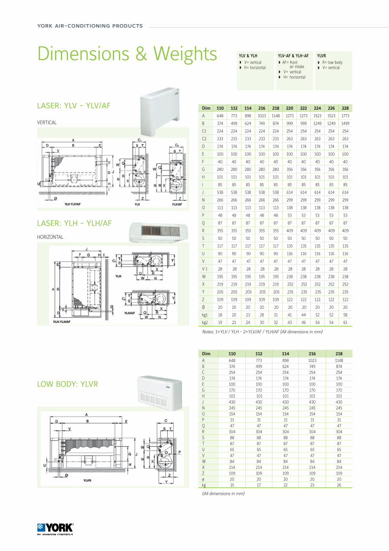
york air-conditioning products
LASER: YLV - YLV/AF
LASER: YLH - YLH/AF
Dim 110 112 114 216 218 220 222 224 226 228
A 648 773 898 1023 1148 1273 1273 1523 1523 1773
B 374 499 624 749 874 999 999 1249 1249 1499
C1 224 224 224 224 224 254 254 254 254 254
C2 233 233 233 233 233 263 263 263 263 263
D 174 174 174 174 174 174 174 174 174 174
E 100 100 100 100 100 100 100 100 100 100
F 40 40 40 40 40 40 40 40 40 40
G 280 280 280 280 280 356 356 356 356 356
H 101 101 101 101 101 101 101 101 101 101
I 85 85 85 85 85 85 85 85 85 85
J 538 538 538 538 538 614 614 614 614 614
N 266 266 266 266 266 299 299 299 299 299
O 113 113 113 113 113 138 138 138 138 138
P 48 48 48 48 48 53 53 53 53 53
Q 87 87 87 87 87 87 87 87 87 87
R 355 355 355 355 355 409 409 409 409 409
S 50 50 50 50 50 50 50 50 50 50
T 117 117 117 117 117 135 135 135 135 135
U 90 90 90 90 90 116 116 116 116 116
V 47 47 47 47 47 47 47 47 47 47
V 1 28 28 28 28 28 28 28 28 28 28
W 195 195 195 195 195 238 238 238 238 238
X 219 219 219 219 219 252 252 252 252 252
Y 205 205 205 205 205 235 235 235 235 235
Z 109 109 109 109 109 122 122 122 122 122
Ø 20 20 20 20 20 20 20 20 20 20
kg1 18 20 23 28 31 41 44 52 52 58
kg2 19 21 24 30 32 43 46 54 54 61
Notes: 1=YLV / YLH - 2=YLV/AF / YLH/AF (All dimensions in mm)
YLV & YLH V= vertical H= horizontal
YLV-AF & YLH-AF AF= front air intake V= vertical H= horizontal
Dimensions & Weights YLVR R= low body V= vertical
VERTICAL
HORIZONTAL
LOW BODY: YLVR
Dim 110 112 114 216 218 A 648 773 898 1023 1148B 374 499 624 749 874C 254 254 254 254 254D 174 174 174 174 174E 100 100 100 100 100G 170 170 170 170 170H 101 101 101 101 101J 430 430 430 430 430N 245 245 245 245 245O 154 154 154 154 154P 31 31 31 31 31Q 47 47 47 47 47R 304 304 304 304 304S 88 88 88 88 88T 87 87 87 87 87U 65 65 65 65 65V 47 47 47 47 47W 84 84 84 84 84X 214 214 214 214 214Z 109 109 109 109 109ø 20 20 20 20 20kg 15 17 22 23 26
(All dimensions in mm)
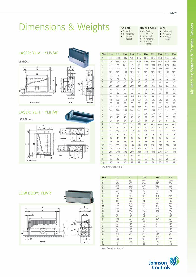
74/75
Air
Han
dlin
g Sy
stem
s &
Ter
min
al D
evic
es
LASER: YLIV - YLIV/AF Dim 110 112 114 216 218 220 222 224 226 228
A 555 680 805 930 1055 1180 1180 1430 1430 1680
A 1 574 699 824 949 1074 1199 1199 1449 1449 1699
B 374 499 624 749 874 999 999 1249 1249 1499
C 215 215 215 215 215 245 245 245 245 245
D 109 109 109 109 109 109 109 109 109 109
D 1 128 128 128 128 128 128 128 128 128 128
E 72 72 72 72 72 72 72 72 72 72
F 40 40 40 40 40 40 40 40 40 40
G 280 280 280 280 280 356 356 356 356 356
H 101 101 101 101 101 101 101 101 101 101
I 85 85 85 85 85 85 85 85 85 85
J 505 505 505 505 505 581 581 581 581 581
K 110 110 110 110 110 125 125 125 125 125
L 55 55 55 55 55 60 60 60 60 60
M 349 474 599 724 849 974 974 1224 1224 1474
N 266 266 266 266 266 299 299 299 299 299
O 113 113 113 113 113 138 138 138 138 138
P 48 48 48 48 48 53 53 53 53 53
Q 87 87 87 87 87 87 87 87 87 87
R 355 355 355 355 355 409 409 409 409 409
S 50 50 50 50 50 50 50 50 50 50
T 117 117 117 117 117 135 135 135 135 135
U 90 90 90 90 90 116 116 116 116 116
V 47 47 47 47 47 47 47 47 47 47
V 1 28 28 28 28 28 28 28 28 28 28
W 195 195 195 195 195 238 238 238 238 238
X 219 219 219 219 219 252 252 252 252 252
Y 200 200 200 200 200 230 230 230 230 230
Z 109 109 109 109 109 122 122 122 122 122
Ø 20 20 20 20 20 20 20 20 20 20
kg 10 13 16 19 22 29 31 38 38 42
(All dimensions in mm)
LASER: YLIH - YLIH/AF
YLIV-AF & YLIH-AF AF= front air intake V= vertical H= horizontal I= without cabinet
YLIV & YLIH V= vertical H= horizontal I= without cabinet
Dimensions & Weights YLIVR R= low body V= vertical I= without cabinet
VERTICAL
HORIZONTAL
Dim 110 112 114 216 218 A 555 680 805 930 1055B 374 499 624 749 874C 230 230 230 230 230D 108 108 108 108 108E 73 73 73 73 73G 170 170 170 170 170H 101 101 101 101 101J 395 395 395 395 395K 61 61 61 61 61L 349 474 599 724 849M 127 127 127 127 127N 245 245 245 245 245O 154 154 154 154 154P 31 31 31 31 31Q 47 47 47 47 47R 304 304 304 304 304S 88 88 88 88 88T 87 87 87 87 87U 65 65 65 65 65V 47 47 47 47 47W 84 84 84 84 84X 214 214 214 214 214Y 201 201 201 201 201Z 109 109 109 109 109ø 20 20 20 20 20kg 9 11 14 16 19
(All dimensions in mm)
LOW BODY: YLIVR

york air-conditioning products
CSL00 (Built in)CSR00 (Wall mounted)
Fan speed selector
CML00 (Built in)CMR00 (Wall mounted)
Thermostatwith manual
fan speed and S/W change over
CEL00 (Built in)CER00 (Wall mounted)Thermostat with manual fan speed and automatic change over
CEL20 (Built in)CER20 (Wall mounted)Thermostat with auto. fan speed and automatic change over
CEL30 (Built in)CER30 (Wall mounted)Thermostat with auto. fan speed and automatic change over for modulating valve
Features CEL/CER• Dead band for change over 5°C or 2°C (factory set
2°C) • Manual fan speeds or automatic (models 20 and 30) • Thermostated fan control or continuous fan running • Option water sensor WS for change over on coil (for
2 pipes) • Led indicated status summer, winter or dead band • Temperature setting for 7 to 30°C (comfort 20-25°C) • Plastic pins for limiting temperature range• Input for window contact • Input for Economy/ occupancy mode • Output for remote alarm • Filter alarm 600 or 1200 running hours (factory set
1200 hours) • With electrical heater post ventilation • With Air sensor in the air intake destratification
function (CEL only)
Compatibility table Thermostats / Valves / Heaters /Parallel connection / Water sensor / Minimum temperature thermostat
Factory fitted thermostat (built in)Valves for 2 pipes Valves for 4 pipes Heaters
Parallel connection Water sensor
Min. Temp. ThermostatON/OFF Modulating
J3A2 (2p) J3AM (2p) J3A2 (4p) J3AM (4p) KREL CBL20 CBL30 WS TMCSL00 Fan speed selector l l
CML00 Thermostat with manual fan speed and S/W change over l l l l
CEL00 Thermostat with manual fan speed, dead band, automatic change over
l l l l l l
CEL20 Thermostat with automatic fan speed, dead band, automatic change over
l l l l l l
CEL30 Thermostat with automatic fan speed, dead band, automatic change over for modulating valve
l l l l l
Remote controllers and thermostats (wall mounted)
CSR00 Fan speed selector l l
CMR00 Thermostat with manual fan speed and S/W change over l l l l
CER00 Thermostat with manual fan speed, dead band, automatic change over
l l l l l l
CER20 Thermostat with automatic fan speed, dead band, automatic change over
l l l l l l
CER30 Thermostat with automatic fan speed, dead band, automatic change over for modulating valve
l l l l l
l Compatible Not compatible
LASER and LOW BODYCompatibility tables
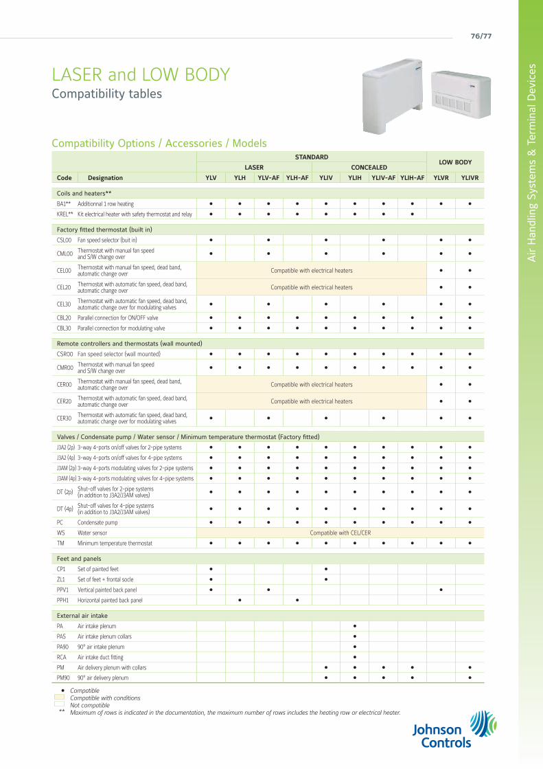
76/77
Air
Han
dlin
g Sy
stem
s &
Ter
min
al D
evic
es
Compatibility Options / Accessories / ModelsSTANDARD
LOW BODYLASER CONCEALED
Code Designation YLV YLH YLV-AF YLH-AF YLIV YLIH YLIV-AF YLIH-AF YLVR YLIVR
Coils and heaters**
BA1** Additionnal 1 row heating l l l l l l l l l l
KREL** Kit electrical heater with safety thermostat and relay l l l l l l l l
Factory fitted thermostat (built in)
CSL00 Fan speed selector (buit in) l l l l l l
CML00 Thermostat with manual fan speed and S/W change over
l l l l l l
CEL00 Thermostat with manual fan speed, dead band, automatic change over Compatible with electrical heaters l l
CEL20 Thermostat with automatic fan speed, dead band, automatic change over Compatible with electrical heaters l l
CEL30 Thermostat with automatic fan speed, dead band, automatic change over for modulating valves
l l l l l l
CBL20 Parallel connection for ON/OFF valve l l l l l l l l l l
CBL30 Parallel connection for modulating valve l l l l l l l l l l
Remote controllers and thermostats (wall mounted)
CSR00 Fan speed selector (wall mounted) l l l l l l l l l l
CMR00 Thermostat with manual fan speed and S/W change over
l l l l l l l l l l
CER00 Thermostat with manual fan speed, dead band, automatic change over Compatible with electrical heaters l l
CER20 Thermostat with automatic fan speed, dead band, automatic change over Compatible with electrical heaters l l
CER30 Thermostat with automatic fan speed, dead band, automatic change over for modulating valves
l l l l l l
Valves / Condensate pump / Water sensor / Minimum temperature thermostat (Factory fitted)
J3A2 (2p) 3-way 4-ports on/off valves for 2-pipe systems l l l l l l l l l l
J3A2 (4p) 3-way 4-ports on/off valves for 4-pipe systems l l l l l l l l l l
J3AM (2p) 3-way 4-ports modulating valves for 2-pipe systems l l l l l l l l l l
J3AM (4p) 3-way 4-ports modulating valves for 4-pipe systems l l l l l l l l l l
DT (2p) Shut-off valves for 2-pipe systems (in addition to J3A2/J3AM valves)
l l l l l l l l l l
DT (4p) Shut-off valves for 4-pipe systems (in addition to J3A2/J3AM valves)
l l l l l l l l l l
PC Condensate pump l l l l l l l l l l
WS Water sensor Compatible with CEL/CER
TM Minimum temperature thermostat l l l l l l l l l l
Feet and panels
CP1 Set of painted feet l l
ZL1 Set of feet + frontal socle l l
PPV1 Vertical painted back panel l l l
PPH1 Horizontal painted back panel l l
External air intake
PA Air intake plenum l
PAS Air intake plenum collars l
PA90 90° air intake plenum l
RCA Air intake duct fitting l
PM Air delivery plenum with collars l l l l l
PM90 90° air delivery plenum l l l l l
Compatible Compatible with conditionsNot compatibleMaximum of rows is indicated in the documentation, the maximum number of rows includes the heating row or electrical heater.
l
**
LASER and LOW BODYCompatibility tables
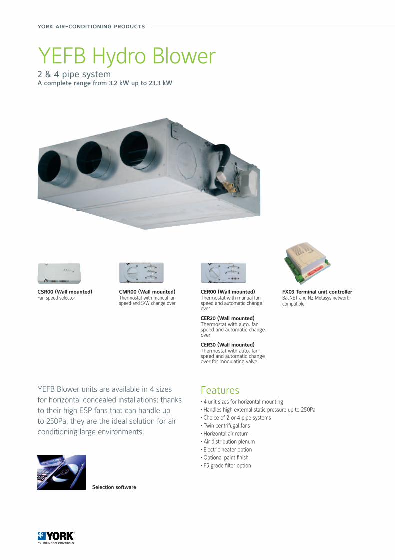
york air-conditioning products
YEFB Hydro Blower2 & 4 pipe systemA complete range from 3.2 kW up to 23.3 kW
Features• 4 unit sizes for horizontal mounting• Handles high external static pressure up to 250Pa• Choice of 2 or 4 pipe systems• Twin centrifugal fans• Horizontal air return• Air distribution plenum• Electric heater option• Optional paint finish• F5 grade filter option
YEFB Blower units are available in 4 sizes for horizontal concealed installations: thanks to their high ESP fans that can handle up to 250Pa, they are the ideal solution for air conditioning large environments.
Selection software
FX03 Terminal unit controllerBacNET and N2 Metasys network compatible
CSR00 (Wall mounted)Fan speed selector
CMR00 (Wall mounted)Thermostat with manual fan speed and S/W change over
CER00 (Wall mounted)Thermostat with manual fan speed and automatic change over
CER20 (Wall mounted)Thermostat with auto. fan speed and automatic change over
CER30 (Wall mounted)Thermostat with auto. fan speed and automatic change over for modulating valve
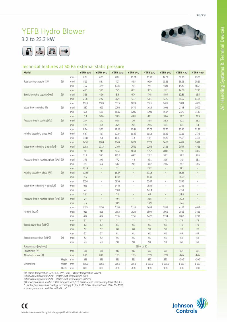
78/79
Air
Han
dlin
g Sy
stem
s &
Ter
min
al D
evic
es
Manufacturer reserves the rights to change specifications without prior notice.
YEFB Hydro Blower3.2 to 23.3 kW
Technical features at 50 Pa external static pressureModel YEFB 130 YEFB 140 YEFB 230 YEFB 240 YEFB 330 YEFB 340 YEFB 430 YEFB 440
Total cooling capacity [kW] (1)
max 6.01 6.92 8.81 10.61 11.15 14.06 17.86 23.31
med 5.13 5.81 7.27 8.55 9.39 11.58 16.28 20.95
min 3.22 3.49 6.08 7.01 7.51 9.00 14.40 18.21
Sensible cooling capacity [kW] (1)
max 4.72 5.29 7.45 8.71 9.13 11.2 14.39 17.73
med 3.95 4.36 5.9 6.74 7.48 8.95 12.86 16.5
min 2.38 2.52 4.79 5.37 5.81 6.75 11.57 13.34
Water flow in cooling [l/h] (1)
max 1033 1189 1515 1824 1916 2417 3071 4008
med 882 999 1250 1470 1615 1991 2798 3602
min 554 600 1045 1205 1291 1547 2475 3130
Pressure drop in cooling [kPa] (1)
max 6.3 20.6 70.9 43.8 45.1 39.6 23.7 21.9
med 27.4 15.2 50.5 30 33.4 28.2 20.1 18.1
min 12.1 6.2 36.9 21.1 22.5 18.1 16.1 14
Heating capacity 2 pipes [kW] (2)
max 8.24 9.25 13.08 15.44 16.02 19.76 25.46 31.27
med 6.87 7.57 10.34 11.89 13.08 15.69 22.69 27.48
min 4.08 4.3 8.36 9.4 10.1 11.72 19.55 23.26
Water flow in heating 2 pipes [l/h] * (2)
max 1430 1604 2269 2678 2779 3426 4414 5421
med 1192 1313 1793 2061 2268 2721 3934 4765
min 708 746 1451 1630 1752 2033 3390 4032
Pressure drop in heating 2 pipes [kPa] (2)
max 51.8 28.3 116.8 69.7 70.2 59.2 38.2 31.6
med 37.6 19.9 77.2 44 49.1 39.5 31 25.1
min 15 7.4 53.2 29.1 31.2 23.6 23.7 18.6
Heating capacity 4 pipes [kW] (3)
max 13.19 - 21 - 25.7 - 41.1 -
med 10.98 - 16.57 - 20.96 - 36.66 -
min 6.5 - 13.37 - 16.17 - 31.58 -
Water flow in heating 4 pipes [l/h] (3)
max 1154 - 1836 - 2247 - 3596 -
med 961 - 1449 - 1833 - 3205 -
min 568 - 1169 - 1414 - 2761 -
Pressure drop in heating 4 pipes [kPa] (3)
max 33.1 - 75 - 45 - 24.8 -
med 24 - 49.4 - 31.5 - 20.2 -
min 9.5 - 33.9 - 19.9 - 15.4 -
Air flow [m3/h]
max 1153 1130 2158 2116 2639 2587 4129 4048
med 916 898 1553 1523 1994 1955 3505 3436
min 494 484 1174 1151 1422 1394 2853 2797
Sound power level [dB(A)]
max 67 67 71 71 71 71 78 78
med 62 62 65 65 65 65 75 75
min 52 52 60 60 59 59 70 70
Sound pressure level [dB(A)] (4)
max 57 57 61 61 62 62 69 69
med 52 52 56 56 56 56 66 66
min 43 43 50 50 50 50 61 61
Power supply [V-ph-Hz] 230 / 1 / 50
Power input [W] max 186 186 419 419 569 569 984 984
Absorbed current [A] max 0.81 0.81 1.95 1.95 2.59 2.59 4.45 4.45
Dimensions
Height mm 331 331 331 331 350 350 439.3 439.3
Width mm 989.6 989.6 989.6 989.6 1 239.6 1 239.6 1 633 1 633
Depth mm 800 800 800 800 900 900 900 900
(1) Room temperature 27°C d.b., 19°C w.b. - Water temperature 7/12 °C(2) Room temperature 20°C - Water inlet temperature: 50°C(3) Room temperature 20°C - Water inlet temperature: 70/60°C(4) Sound pressure level in a 100 m2 room, at 1,5 m distance and riverberating time of 0,3 s.* Water flow values as Cooling, accordingly to the EUROVENT standards and UNI ENV 13974 pipe system not available with 4R coil

york air-conditioning products
YGFC Fan Coil Unit2 & 4 pipe systemA complete range from 1.9 kW to 14 kW
Features• 10 unit sizes, suitable for horizontal or vertical mounting• Models with or without casing• 3 speed ‘whisper quiet’ fans• District cooling coil option allows reduction in pump power and increase in system efficiency
• Single coil 3, or 4 rows• Double coil 3 or 4 rows (cooling) & 1 row (heating)• Electric heating option• Suction and delivery plenum option• Range of coil protection options for increased product longevity
Commercial Fan Coil Unit range, the YGFC Series is designed specially to meet the varied requirements of zone cooling or heating using chilled water or hot water. However in order to meet the growing demand in city centres where loads are high and space at a premium, YGFC units have a coil option suitable for use in ‘district cooling’ systems, thus helping reduce pumping power while increasing the overall system efficiency.
Selection software
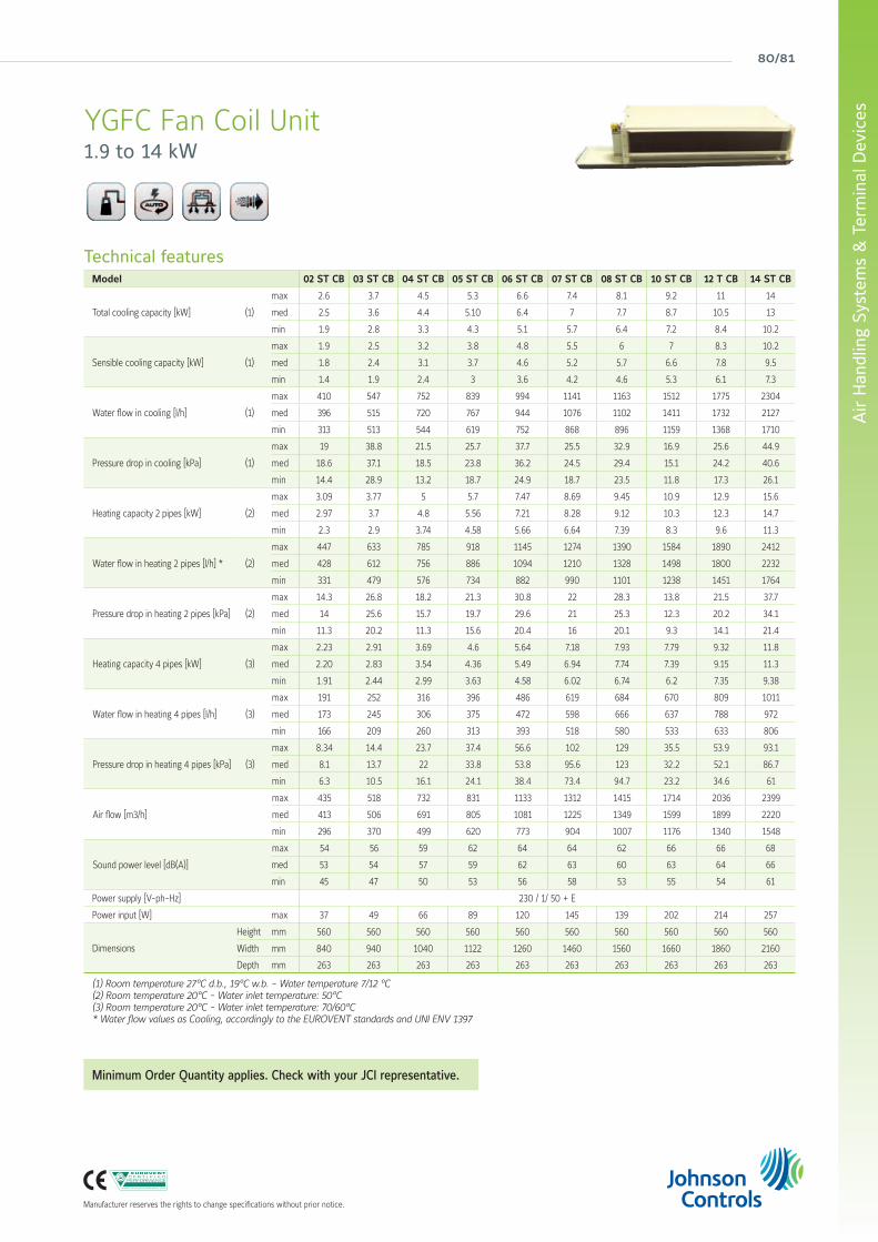
80/81
Air
Han
dlin
g Sy
stem
s &
Ter
min
al D
evic
es
Manufacturer reserves the rights to change specifications without prior notice.
YGFC Fan Coil Unit1.9 to 14 kW
Technical featuresModel 02 ST CB 03 ST CB 04 ST CB 05 ST CB 06 ST CB 07 ST CB 08 ST CB 10 ST CB 12 T CB 14 ST CB
Total cooling capacity [kW] (1)
max 2.6 3.7 4.5 5.3 6.6 7.4 8.1 9.2 11 14
med 2.5 3.6 4.4 5.10 6.4 7 7.7 8.7 10.5 13
min 1.9 2.8 3.3 4.3 5.1 5.7 6.4 7.2 8.4 10.2
Sensible cooling capacity [kW] (1)
max 1.9 2.5 3.2 3.8 4.8 5.5 6 7 8.3 10.2
med 1.8 2.4 3.1 3.7 4.6 5.2 5.7 6.6 7.8 9.5
min 1.4 1.9 2.4 3 3.6 4.2 4.6 5.3 6.1 7.3
Water flow in cooling [l/h] (1)
max 410 547 752 839 994 1141 1163 1512 1775 2304
med 396 515 720 767 944 1076 1102 1411 1732 2127
min 313 513 544 619 752 868 896 1159 1368 1710
Pressure drop in cooling [kPa] (1)
max 19 38.8 21.5 25.7 37.7 25.5 32.9 16.9 25.6 44.9
med 18.6 37.1 18.5 23.8 36.2 24.5 29.4 15.1 24.2 40.6
min 14.4 28.9 13.2 18.7 24.9 18.7 23.5 11.8 17.3 26.1
Heating capacity 2 pipes [kW] (2)
max 3.09 3.77 5 5.7 7.47 8.69 9.45 10.9 12.9 15.6
med 2.97 3.7 4.8 5.56 7.21 8.28 9.12 10.3 12.3 14.7
min 2.3 2.9 3.74 4.58 5.66 6.64 7.39 8.3 9.6 11.3
Water flow in heating 2 pipes [l/h] * (2)
max 447 633 785 918 1145 1274 1390 1584 1890 2412
med 428 612 756 886 1094 1210 1328 1498 1800 2232
min 331 479 576 734 882 990 1101 1238 1451 1764
Pressure drop in heating 2 pipes [kPa] (2)
max 14.3 26.8 18.2 21.3 30.8 22 28.3 13.8 21.5 37.7
med 14 25.6 15.7 19.7 29.6 21 25.3 12.3 20.2 34.1
min 11.3 20.2 11.3 15.6 20.4 16 20.1 9.3 14.1 21.4
Heating capacity 4 pipes [kW] (3)
max 2.23 2.91 3.69 4.6 5.64 7.18 7.93 7.79 9.32 11.8
med 2.20 2.83 3.54 4.36 5.49 6.94 7.74 7.39 9.15 11.3
min 1.91 2.44 2.99 3.63 4.58 6.02 6.74 6.2 7.35 9.38
Water flow in heating 4 pipes [l/h] (3)
max 191 252 316 396 486 619 684 670 809 1011
med 173 245 306 375 472 598 666 637 788 972
min 166 209 260 313 393 518 580 533 633 806
Pressure drop in heating 4 pipes [kPa] (3)
max 8.34 14.4 23.7 37.4 56.6 102 129 35.5 53.9 93.1
med 8.1 13.7 22 33.8 53.8 95.6 123 32.2 52.1 86.7
min 6.3 10.5 16.1 24.1 38.4 73.4 94.7 23.2 34.6 61
Air flow [m3/h]
max 435 518 732 831 1133 1312 1415 1714 2036 2399
med 413 506 691 805 1081 1225 1349 1599 1899 2220
min 296 370 499 620 773 904 1007 1176 1340 1548
Sound power level [dB(A)]
max 54 56 59 62 64 64 62 66 66 68
med 53 54 57 59 62 63 60 63 64 66
min 45 47 50 53 56 58 53 55 54 61
Power supply [V-ph-Hz] 230 / 1/ 50 + E
Power input [W] max 37 49 66 89 120 145 139 202 214 257
Dimensions
Height mm 560 560 560 560 560 560 560 560 560 560
Width mm 840 940 1040 1122 1260 1460 1560 1660 1860 2160
Depth mm 263 263 263 263 263 263 263 263 263 263
(1) Room temperature 27°C d.b., 19°C w.b. - Water temperature 7/12 °C(2) Room temperature 20°C - Water inlet temperature: 50°C(3) Room temperature 20°C - Water inlet temperature: 70/60°C* Water flow values as Cooling, accordingly to the EUROVENT standards and UNI ENV 1397
Minimum Order Quantity applies. Check with your JCI representative.

york air-conditioning products
YHK Hydro Cassette2 & 4 pipe systemA complete range from 1.3 kW to 11.1 kW
Features• Cooling duty from 1.3 to 11.1 kW• 2 & 4 pipes systems in all range• 2 sizes: 600 x 600 & 800 x 800• Possible choice between 6 fan speeds• Condensate pump integrated in all range• 2/3 way valves fitted or supplied loose in all range• Coloured versions, possible to change the colour of the grill and the frame
• Possible to select a complete range of controls• Electric heater fitted as an option for all range (2 pipe only)• All metal parts insulated to avoid condensations
YHK Hydro Cassette units are simple and elegant, discreet in their design. High standards of quality and reliability, combined with a wide range of accessories ensure a total solution for all comfort cooling and heating requirements.
Coloured versions available as an option
Selection software
Wired controlsBRRemote three speeds controller
TRBR + Electronic thermostat and Summer/Winter switch
ATRAutomatic TR
DTRDigital AutomaticRemote controller
TMO 503 SV2Digital Automatic Remote controller to be mounted in the standard light wall box
DRC - DICentralized controller up to 60 terminals
Infrared control
FX03 Terminal unit controllerBacNET and N2 Metasys network compatible
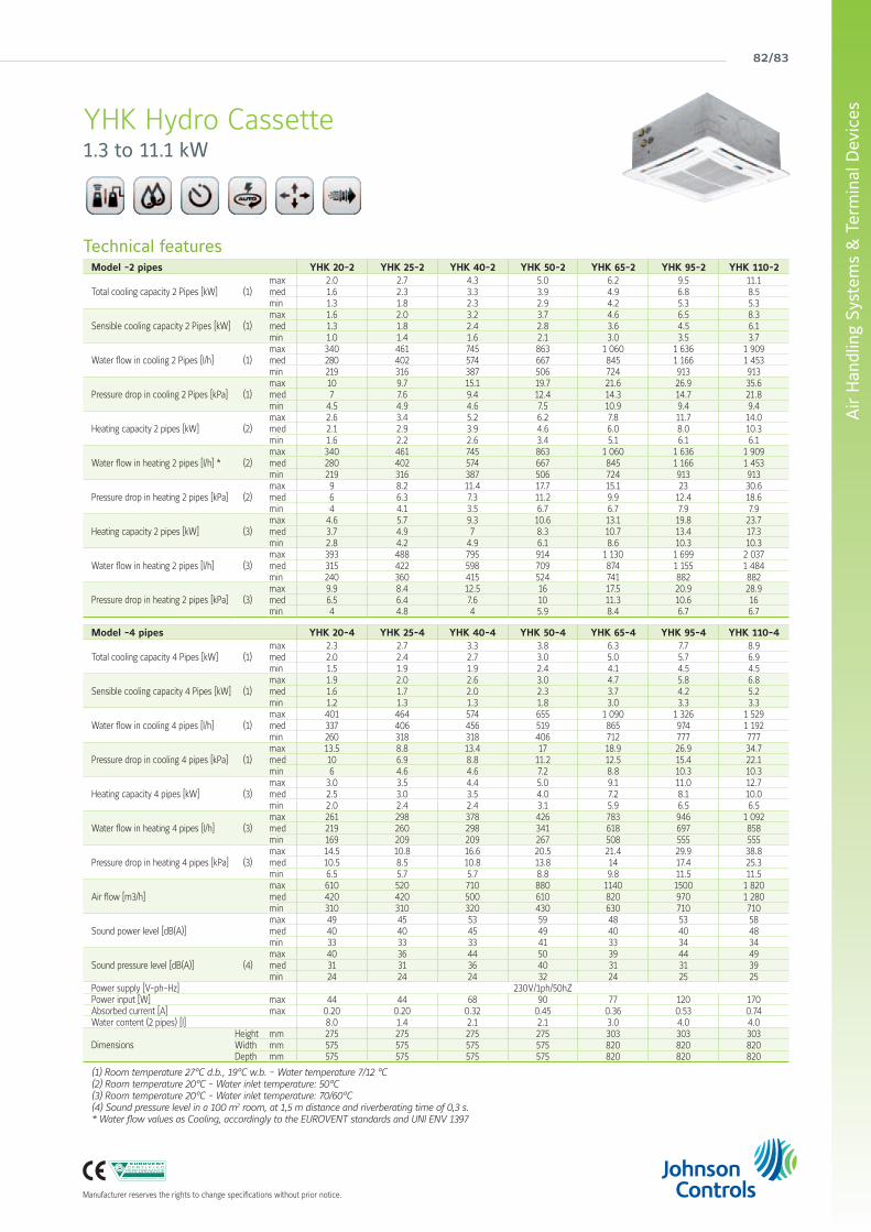
82/83
Air
Han
dlin
g Sy
stem
s &
Ter
min
al D
evic
es
Manufacturer reserves the rights to change specifications without prior notice.
YHK Hydro Cassette1.3 to 11.1 kW
Technical featuresModel -2 pipes YHK 20-2 YHK 25-2 YHK 40-2 YHK 50-2 YHK 65-2 YHK 95-2 YHK 110-2
Total cooling capacity 2 Pipes [kW] (1) max 2.0 2.7 4.3 5.0 6.2 9.5 11.1 med 1.6 2.3 3.3 3.9 4.9 6.8 8.5 min 1.3 1.8 2.3 2.9 4.2 5.3 5.3
Sensible cooling capacity 2 Pipes [kW] (1) max 1.6 2.0 3.2 3.7 4.6 6.5 8.3 med 1.3 1.8 2.4 2.8 3.6 4.5 6.1 min 1.0 1.4 1.6 2.1 3.0 3.5 3.7
Water flow in cooling 2 Pipes [l/h] (1) max 340 461 745 863 1 060 1 636 1 909 med 280 402 574 667 845 1 166 1 453 min 219 316 387 506 724 913 913
Pressure drop in cooling 2 Pipes [kPa] (1) max 10 9.7 15.1 19.7 21.6 26.9 35.6 med 7 7.6 9.4 12.4 14.3 14.7 21.8 min 4.5 4.9 4.6 7.5 10.9 9.4 9.4
Heating capacity 2 pipes [kW] (2) max 2.6 3.4 5.2 6.2 7.8 11.7 14.0 med 2.1 2.9 3.9 4.6 6.0 8.0 10.3 min 1.6 2.2 2.6 3.4 5.1 6.1 6.1
Water flow in heating 2 pipes [l/h] * (2) max 340 461 745 863 1 060 1 636 1 909 med 280 402 574 667 845 1 166 1 453 min 219 316 387 506 724 913 913
Pressure drop in heating 2 pipes [kPa] (2) max 9 8.2 11.4 17.7 15.1 23 30.6 med 6 6.3 7.3 11.2 9.9 12.4 18.6 min 4 4.1 3.5 6.7 6.7 7.9 7.9
Heating capacity 2 pipes [kW] (3) max 4.6 5.7 9.3 10.6 13.1 19.8 23.7 med 3.7 4.9 7 8.3 10.7 13.4 17.3 min 2.8 4.2 4.9 6.1 8.6 10.3 10.3
Water flow in heating 2 pipes [l/h] (3) max 393 488 795 914 1 130 1 699 2 037 med 315 422 598 709 874 1 155 1 484 min 240 360 415 524 741 882 882
Pressure drop in heating 2 pipes [kPa] (3) max 9.9 8.4 12.5 16 17.5 20.9 28.9 med 6.5 6.4 7.6 10 11.3 10.6 16min 4 4.8 4 5.9 8.4 6.7 6.7
Model -4 pipes YHK 20-4 YHK 25-4 YHK 40-4 YHK 50-4 YHK 65-4 YHK 95-4 YHK 110-4
Total cooling capacity 4 Pipes [kW] (1) max 2.3 2.7 3.3 3.8 6.3 7.7 8.9 med 2.0 2.4 2.7 3.0 5.0 5.7 6.9 min 1.5 1.9 1.9 2.4 4.1 4.5 4.5
Sensible cooling capacity 4 Pipes [kW] (1) max 1.9 2.0 2.6 3.0 4.7 5.8 6.8 med 1.6 1.7 2.0 2.3 3.7 4.2 5.2 min 1.2 1.3 1.3 1.8 3.0 3.3 3.3
Water flow in cooling 4 pipes [l/h] (1) max 401 464 574 655 1 090 1 326 1 529 med 337 406 456 519 865 974 1 192 min 260 318 318 406 712 777 777
Pressure drop in cooling 4 pipes [kPa] (1) max 13.5 8.8 13.4 17 18.9 26.9 34.7 med 10 6.9 8.8 11.2 12.5 15.4 22.1 min 6 4.6 4.6 7.2 8.8 10.3 10.3
Heating capacity 4 pipes [kW] (3) max 3.0 3.5 4.4 5.0 9.1 11.0 12.7 med 2.5 3.0 3.5 4.0 7.2 8.1 10.0 min 2.0 2.4 2.4 3.1 5.9 6.5 6.5
Water flow in heating 4 pipes [l/h] (3) max 261 298 378 426 783 946 1 092 med 219 260 298 341 618 697 858min 169 209 209 267 508 555 555
Pressure drop in heating 4 pipes [kPa] (3) max 14.5 10.8 16.6 20.5 21.4 29.9 38.8 med 10.5 8.5 10.8 13.8 14 17.4 25.3 min 6.5 5.7 5.7 8.8 9.8 11.5 11.5
Air flow [m3/h] max 610 520 710 880 1140 1500 1 820 med 420 420 500 610 820 970 1 280 min 310 310 320 430 630 710 710
Sound power level [dB(A)] max 49 45 53 59 48 53 58med 40 40 45 49 40 40 48min 33 33 33 41 33 34 34
Sound pressure level [dB(A)] (4) max 40 36 44 50 39 44 49med 31 31 36 40 31 31 39min 24 24 24 32 24 25 25
Power supply [V-ph-Hz] 230V/1ph/50hZPower input [W] max 44 44 68 90 77 120 170Absorbed current [A] max 0.20 0.20 0.32 0.45 0.36 0.53 0.74 Water content (2 pipes) [l] 8.0 1.4 2.1 2.1 3.0 4.0 4.0
Dimensions Height mm 275 275 275 275 303 303 303Width mm 575 575 575 575 820 820 820Depth mm 575 575 575 575 820 820 820
(1) Room temperature 27°C d.b., 19°C w.b. - Water temperature 7/12 °C(2) Room temperature 20°C - Water inlet temperature: 50°C(3) Room temperature 20°C - Water inlet temperature: 70/60°C(4) Sound pressure level in a 100 m2 room, at 1,5 m distance and riverberating time of 0,3 s.* Water flow values as Cooling, accordingly to the EUROVENT standards and UNI ENV 1397

york air-conditioning products
YHK-ECM Inverter Hydro Cassette2 & 4 pipe systemA complete range from 1.8 kW to 10.8 kW
Features• Cooling duty from 1.8 to 10.8 kW • YHKH: models with infrared control (standard)• YHKY: models with wired control (accessory)• 2 (-2) & 4 (-4 or -6) pipes systems• 2 sizes: 600 x 600 & 800 x 800 • Condensate pump integrated in all range • 2/3 way valves fitted or supplied loose in all range • Coloured versions, possible to change the colour of the grid and the frame
• All metal parts insulated to avoid condensations • Inverter fan motor for a very quiet operation • Electrical consumption reduced by up to 75% • Specific range of controllers with master-slave function
YHK ECM water cassette is the result of significant technical and design research focused on providing an avant-garde product in terms of performance, low noise and control flexibility. YHK ECM series uses an innovative brushless electric motor controlled by an inverter card that varies the air flow continuously by means of a 1-10 V signal. The extreme efficiency, also at a low speed, makes it possible to greatly reduce electrical consumption (more than 75% less in comparison to a traditional motor) with absorption values, under normal operating conditions, that are no greater than 10 Watt in the entire range.
Wired controlETN-ECMWall-mounted controller that can be connected allowing an inverter control with a 0-10V signal. The same controller can be connected to one or several cassettes (master-slave function).
Infrared control
Coloured versions available as an option
Selection software
FX03 Terminal unit controllerBacNET and N2 Metasys network compatible

84/85
Air
Han
dlin
g Sy
stem
s &
Ter
min
al D
evic
es
Manufacturer reserves the rights to change specifications without prior notice.
Condensate pump integrated in all sizes
Metal parts insulatedto avoid condensation
2 or 3 way valves fittedor supplied loosein all sizes
Outer casing as an option to integrate the water cassette into any enviroment
YHK-ECM Inverter Hydro Cassette1.8 to 10.8 kW
Technical featuresModel -2 pipes YHK-ECM 25-2 YHK-ECM 40-2 YHK-ECM 50-2 YHK-ECM 65-2 YHK-ECM 95-2
Total cooling capacity 2 Pipes [kW] (1) max 2.8 4.3 5.0 6.3 10.8med 2.2 3.1 3.9 5.2 7.7min 1.8 2.2 2.6 4.2 5.3
Sensible cooling capacity 2 Pipes [kW] (1) max 2.1 3.2 3.7 4.7 7.9med 1.6 2.2 2.8 3.8 5.5min 1.4 1.6 1.8 3.0 3.7
Water flow in cooling 2 Pipes [l/h] (1) max 473 744 864 1 089 1 848med 373 524 666 885 1 328min 317 385 441 723 909
Pressure drop in cooling 2 Pipes [kPa] (1) max 10.1 15.1 19.7 22.7 33.6med 6.6 9.4 12.4 15.6 18.5min 4.9 4.6 5.9 10.9 9.4
Heating capacity 2 pipes [kW] (2) max 3.4 5.2 6.2 8.0 12.7med 2.7 3.6 4.6 6.4 8.8min 2.2 2.6 3.0 5.1 5.9
Pressure drop in heating 2 pipes [kPa] (2) max 8.7 13.1 17.7 19.5 28.8med 5.5 6.6 10.5 12.8 14.9min 4.0 3.6 4.7 8.7 7.2
Model -4 pipes YHK-ECM 25-4 YHK-ECM 40-6 YHK-ECM 50-6 YHK-ECM 65-4 YHK-ECM 95-6
Total cooling capacity 4 Pipes [kW] (1) max 2.8 3.9 4.5 6.5 9.9med 2.2 2.8 3.5 5.3 7.2min 1.9 2.1 2.4 4.3 5.0
Sensible cooling capacity 4 Pipes [kW] (1) max 2.1 3.0 3.5 4.8 7.4med 1.6 2.0 2.6 3.8 5.2min 1.3 1.5 1.7 3.1 3.5
Water flow in cooling 4 pipes [l/h] (1) max 476 676 779 1 120 1 697med 375 483 608 908 1 233min 318 359 409 740 856
Pressure drop in cooling 4 pipes [kPa] (1) max 9.5 10.5 13.1 19.8 30.1med 6.2 5.7 8.4 13.6 17.0min 4.6 3.5 4.1 9.4 8.8
Heating capacity 4 pipes [kW] (3) max 3.6 3.4 3.8 9.4 9.5med 2.9 2.5 3.1 7.5 7.2min 2.4 2.0 2.2 6.1 5.2
Water flow in heating 4 pipes [l/h] (3) max 311 288 326 805 818med 245 217 263 649 616min 209 170 189 528 449
Pressure drop in heating 4 pipes [kPa] (3) max 11.7 9.0 11.0 22.5 18.0med 7.6 5.5 7.5 15.5 11.0min 5.7 3.5 4.5 10.5 6.5
Air flow [m3/h] max 535 710 880 1 165 1 770med 380 445 610 870 1 130min 310 310 360 630 710
Sound power level [dB(A)] max 47 54 60 48 57med 39 43 50 39 47min 33 33 37 33 34
Sound pressure level [dB(A)] (4) max 38 45 51 39 48med 30 34 41 30 38min 24 24 28 24 25
Power supply [V-ph-Hz] 230V/1ph/50hZPower input [W] max 16 31 62 53 108Water content (2 pipes) [l] 1.4 2.1 2.1 3.0 4.0
Dimensions Height mm 275 275 275 303 303 Width mm 575 575 575 820 820 Depth mm 575 575 575 820 820
(1) Room temperature 27°C d.b., 19°C w.b. - Water temperature 7/12 °C(2) Room temperature 20°C - Water inlet temperature: 50°C(3) Room temperature 20°C - Water inlet temperature: 70/60°C(4) Sound pressure level in a 100 m2 room, at 1,5 m distance and riverberating time of 0,3 s.* Water flow values as Cooling, accordingly to the EUROVENT standards and UNI ENV 1397

york air-conditioning products
Compatibility table / CodesModel (Panel not included) YHK 20 YHK 25 YHK 40 YHK 50 YHK 65 YHK 95 YHK 110
Cassette YHKY 2 pipe system 0079100K 0079000K 0079001K 0079002K 0079003K 0079004K 0079005K4 pipe system 0079110K 0079010K 0079011K 0079012K 0079013K 0079014K 0079015K
Cassette YHKH - with infrared remote control included2 pipe system 0079140K 0079040K 0079041K 0079042K 0079043K 0079044K 0079045K4 pipe system 0079150K 0079050K 0079051K 0079052K 0079053K 0079054K 0079055K
Cassette YHKY-ECM - basic model2 pipe system - 0079801K 0079802K 0079803K 0079804K 0079805K -
4 pipe system - 0079811K 0079812K 0079813K 0079814K 0079815K -
Cassette YHKH-ECM - basic model2 pipe system - 0079821K 0079822K 0079823K 0079824K 0079825K -
4 pipe system - 0079831K 0079832K 0079833K 0079834K 0079835K -
Options (Factory fitted)
Cassette YHKY-E - with electric resistance
Version without infrared remote control YHKY-E 2 pipe system - 0079060K 0079061K 0079062K 0079063K 0079064K 0079065KVersion with infrared remote control included YHKH-E 2 pipe system - 0079080K 0079081K 0079082K 0079083K 0079084K 0079085K
Cassette YHKY-REB - with remote electric board
Cassette YHKY-REB2 pipe system 0079120K 0079020K 0079021K 0079022K 0079023K 0079024K 0079025K4 pipe system 0079130K 0079030K 0079031K 0079032K 0079033K 0079034K 0079035K
Valves3 way valve + mounting kit for 2 pipe models(factory fitted)
9079510 l -
9079511 - l
3 way valve + mounting kit for 4 pipe models(factory fitted)
9079512 l -
9079513 - l
Accessories (supplied loose)
Air diffusers / PanelsAir diffuser - intake grid, frame and louvres in RAL 9003 white colour
AKPA 600 l -
AKPA 800 - l
Air diffuser - other colours (*) Contact Johnson Controls
Valves (220V On/Off)
3 way valve + mounting kitfor 2 pipe models (not fitted)
9079500 l -
9079501 - l
3 way valve + mounting kitfor 4 pipe models (not fitted)
9079502 l -
9079503 - l
2 way valve + mounting kitfor 2 pipe models (not fitted)
9079505 l -
9079506 - l
2 way valve + mounting kitfor 4 pipe models (not fitted)
9079507 l -
9079508 - l
3 way valve + mounting kit for units with outer casing OCA (not fitted) 9079155 l -
3 way valve + mounting kit for units with outer casing OCA (not fitted) 9079156 - l
Other type of valvesOther valves Contact Johnson Controls
Other Accessories
Outer casingOCA 600 l -
OCA 800 - l
Fresh air duct FAD l
Fresh air kit 1 way for units with outer casing OCA FAK 600 l -
Fresh air kit 1 way for units with outer casing OCA FAK 800 - l
CONTROLS for YHKY versionsRemote three speed control BR 9060540 l
Remote three speed control + electronic thermostat and S/W switch TR 9060541 l
Automatic speed control with electronic thermostat and S/W - ATR 9060542 l
Automatic speed control with electronic thermostat to be mounted in the light wall box TMO-503-SV2 9060172 l
Receiver REC-S 9079110 l
Automatic remote control with electronic thermostat, S/W swithc and liquid crystall display DTR 9060521 l
Receiver (slave) for control DTR RECD 9060139 l
Change over CH 15-25 9053049 l
Low temperature cut out thermostat TME 3021091 l
CONTROLS for YHKH versionsDigital remote control up to 60 multifunction units DRC-DI 9079102 l
Change over for infrared remote control CH T2 9079103 l
CONTROLS only for YHK-ECM versionDigital remote control up to 60 multifunction units DRC-DI 9079102 l
ETM-ECM control 3021232 l
RT03/ECM infrared remote control 9079220 l
Maxinet management system for a network of cassette fan coilMaxinet 9079104 l
Board 8 relais for Maxinet 9079105 l
(*) Minimum order quantity : 20 units
Options & Accessories
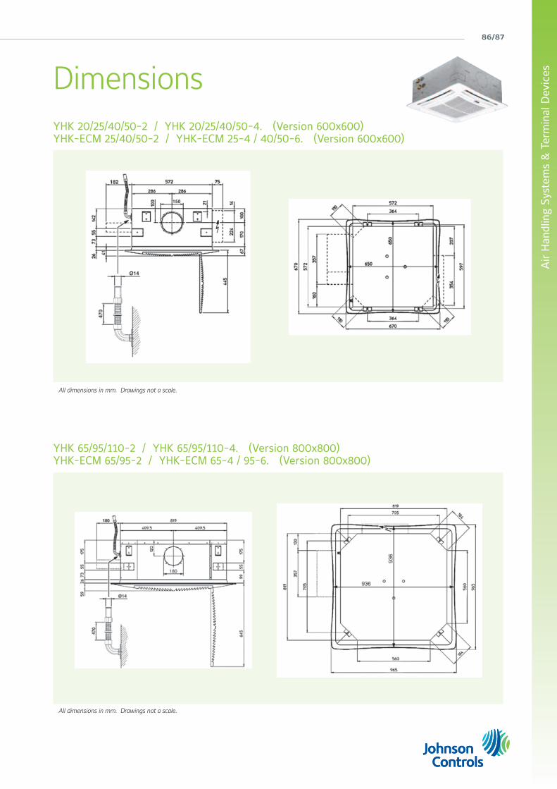
86/87
Air
Han
dlin
g Sy
stem
s &
Ter
min
al D
evic
es
All dimensions in mm. Drawings not a scale.
All dimensions in mm. Drawings not a scale.
YHK 20/25/40/50-2 / YHK 20/25/40/50-4. (Version 600x600)YHK-ECM 25/40/50-2 / YHK-ECM 25-4 / 40/50-6. (Version 600x600)
YHK 65/95/110-2 / YHK 65/95/110-4. (Version 800x800)YHK-ECM 65/95-2 / YHK-ECM 65-4 / 95-6. (Version 800x800)
Dimensions

york air-conditioning products
YFCC Coanda Hydro Cassette2 & 4 pipe systemA complete range from 0.9 kW to 4.0 kW
Features• Coanda effect units, allowing easier and cheaper installation • Cooling duty from 0.9 to 4.0 kW • 2 & 4 pipes systems in all range • 3 sizes: 600 x 600, 600 x 1000 & 600 x 1200 • 2/3 way valves fitted or supplied loose in all range • Left and right hand (optional) water connections • 6 fan speeds (3 pre-wired) • Air throw till 7.6m (cooling) and 9.5m (heating)
Thanks to its unique diffuser, YFCC cassette units generate an airflow with a “coanda” effect. The unit is suitable for installation in a suspended ceiling. Air intake is from the bottom while the air is supplied parallel to the ceiling.
The resulting “coanda” effect creates excellent draft free distribution of the air inside the room.Units can be supplied with 1 coil (2 pipe system) with optional electric heating element, or with 2 coils (4 pipe system) with one or two rows.
Selection software
Coanda effect
Wired controlsBRRemote three speeds controller
TRBR + Electronic thermostat and Summer/Winter switch
ATRAutomatic TR
DTRDigital AutomaticRemote controller
TMO 503 SV2Digital Automatic Remote controller to be mounted in the standard light wall box
DRC - DICentralized controller up to 60 terminals
Infrared control

88/89
Air
Han
dlin
g Sy
stem
s &
Ter
min
al D
evic
es
Manufacturer reserves the rights to change specifications without prior notice.
YFCC Coanda Hydro Cassette0.9 to 4.0 kW
Technical featuresModel -2 pipes YFCC 130 YFCC 140 YFCC 230 YFCC 240 YFCC 330 YFCC 340
Total cooling capacity 2 Pipes [kW] (1) max 1.5 1.7 2.4 2.6 3.3 4.0med 1.1 1.2 1.6 1.7 2.8 3.6min 0.9 1.0 1.4 1.4 2.0 2.5
Sensible cooling capacity 2 Pipes [kW] (1) max 1.2 1.3 1.8 1.9 2.5 3.0med 0.8 0.9 1.2 1.2 2.1 2.6min 0.7 0.7 1.0 1.0 1.4 1.8
Pressure drop in cooling 2 Pipes [kPa] (1) max 6.1 12.9 7.6 12.1 16.2 15.5med 3.3 6.7 3.9 6.0 12.1 12.6min 2.4 4.7 2.9 4.4 6.4 6.7
Heating capacity 2 pipes [kW] (2) max 1.9 2.1 2.9 3.1 4.0 4.8med 1.3 1.4 1.9 2.0 3.4 4.2min 1.1 1.1 1.6 1.7 2.3 2.9
Pressure drop in heating 2 pipes [kPa] (2) max 4.9 10.7 6.3 10.2 13.4 12.6med 2.6 5.4 3.1 4.8 9.8 10.0min 1.8 3.7 2.3 3.5 5.2 5.5
Air flow [m3/h] max 280 280 380 380 540 620med 180 180 240 240 440 540min 140 140 200 200 290 360
Sound power level [dB(A)] max 52 52 48 48 52 55med 41 41 36 36 46 52min 35 35 33 33 35 41
Sound pressure level [dB(A)] (4) max 43 43 39 39 43 46med 32 32 27 27 37 43min 26 26 24 24 26 32
Power supply [V-ph-Hz] 230V/1ph/50HzPower input [W] max 49 44 59 49 44 72
Dimensions Height mm 309 309 309 309 309 309Width mm 592 592 592 592 592 592Depth mm 592 592 970 970 1 192 1 192
Model -4 pipes YFCC 130+1 YFCC 230+1 YFCC 330+1
Total cooling capacity 4 Pipes [kW] (1) max 1.5 2.4 3.3med 1.1 1.6 2.8min 0.9 1.4 2.0
Sensible cooling capacity 4 Pipes [kW] (1) max 1.2 1.8 2.5med 0.8 1.2 2.1min 0.7 1.0 1.4
Pressure drop in cooling 4 pipes [kPa] (1) max 6.1 7.6 16.2med 3.3 3.9 12.1min 2.4 2.9 6.4
Heating capacity 4 pipes [kW] (3) max 1.5 2.4 3.3med 1.1 1.7 2.9min 0.9 1.5 2.1
Pressure drop in heating 4 pipes [kPa] (3) max 3.6 2.0 4.3med 2.1 1.2 3.4min 1.6 0.9 2.0
Air flow [m3/h] max 280 380 540med 180 240 440min 140 200 290
Sound power level [dB(A)] max 52 48 52med 41 36 46min 35 33 35
Sound pressure level [dB(A)] (4) max 43 39 43med 32 27 37min 26 24 26
Power supply [V-ph-Hz] 230V/1ph/50HzPower input [W] max 49 44 59
Dimensions Height mm 309 309 309Width mm 592 592 592Depth mm 592 970 1 192
(1) Room temperature 27°C d.b., 19°C w.b. - Water temperature 7/12 °C(2) Room temperature 20°C - Water inlet temperature: 50°C(3) Room temperature 20°C - Water inlet temperature: 70/60°C(4) Sound pressure level in a 100 m2 room, at 1,5 m distance and riverberating time of 0,3 s.* Water flow values as Cooling, accordingly to the EUROVENT standards and UNI ENV 1397

york air-conditioning products
YFCC-ECM Coanda Hydro Cassette Inverter2 & 4 pipe systemA complete range from 0.8 kW to 4.0 kW
Features• Coanda effect units, allowing easier and cheaper installation • Cooling duty from 0.8 to 4.0 kW • 2 & 4 pipes systems in all range • 3 sizes: 600 x 600, 600 x 1000 & 600 x 1200 • 2/3 way valves fitted or supplied loose in all range • Left and right hand (optional) water connections • 6 fan speeds (3 pre-wired) • Air throw till 7.6m (cooling) and 9.5m (heating)• ECM variable speed motor
Thanks to its unique diffuser, YFCC cassette units generate an airflow with a “coanda” effect. The unit is suitable for installation in a suspended ceiling. Air intake is from the bottom while the air is supplied parallel to the ceiling.
The resulting “coanda” effect creates excellent draft free distribution of the air inside the room.Units can be supplied with 1 coil (2 pipe system) with optional electric heating element, or with 2 coils (4 pipe system) with one or two rows.
Selection software
Coanda effect
Wired controlsCR-T-ECMContinuous fan speed control with electronic thermostat and s/w switch
Infrared control
ETN-ECMWall-mounted controller that can be connected allowing an inverter control with a 0-10V signal. The same controller can be connected to one or several cassettes (master-slave function).
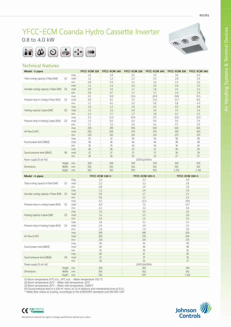
90/91
Air
Han
dlin
g Sy
stem
s &
Ter
min
al D
evic
es
Manufacturer reserves the rights to change specifications without prior notice.
YFCC-ECM Coanda Hydro Cassette Inverter0.8 to 4.0 kW
Technical featuresModel -2 pipes YFCC-ECM 130 YFCC-ECM 140 YFCC-ECM 230 YFCC-ECM 240 YFCC-ECM 330 YFCC-ECM 340
Total cooling capacity 2 Pipes [kW] (1) max 1.6 1.8 3.2 3.5 3.8 4.0med 1.2 1.3 2.3 2.5 2.8 2.9min 0.8 0.9 1.5 1.6 1.9 2.0
Sensible cooling capacity 2 Pipes [kW] (1) max 1.2 1.4 2.4 2.6 2.8 3.0med 0.9 1.0 1.7 1.8 2.1 2.2min 0.6 0.7 1.1 1.1 1.4 1.4
Pressure drop in cooling 2 Pipes [kPa] (1) max 6.5 13.9 12.6 20.8 19.8 15.5med 4.0 8.1 7.3 11.6 11.7 8.9min 2.1 4.1 3.2 5.0 5.8 4.3
Heating capacity 2 pipes [kW] (2) max 2.0 2.2 3.9 4.3 4.5 4.8med 1.5 1.6 2.8 3.0 3.3 3.4min 1.0 1.1 1.7 1.8 2.2 2.3
Pressure drop in heating 2 pipes [kPa] (2) max 5.3 11.6 10.4 17.1 16.6 13.0med 3.3 6.6 6.0 9.4 9.4 7.4min 1.7 3.3 2.6 4.1 4.7 3.5
Air flow [m3/h] max 295 295 540 540 620 620med 205 205 370 370 430 430min 130 130 215 215 275 275
Sound power level [dB(A)] max 55 55 56 56 58 58med 46 46 46 46 48 48min 35 35 34 34 36 36
Sound pressure level [dB(A)] (4) max 46 46 47 47 49 49med 37 37 37 37 39 39min 26 26 25 25 27 27
Power supply [V-ph-Hz] 230V/1ph/50Hz
Dimensions Height mm 309 309 309 309 309 309Width mm 592 592 592 592 592 592Depth mm 592 592 970 970 1 192 1 192
Model -4 pipes YFCC-ECM 130+1 YFCC-ECM 230+1 YFCC-ECM 330+1
Total cooling capacity 4 Pipes [kW] (1) max 1.6 3.2 3.8med 1.2 2.3 2.8min 0.8 1.4 1.8
Sensible cooling capacity 4 Pipes [kW] (1) max 1.2 2.4 2.8med 0.9 1.7 2.1min 0.6 1.1 1.4
Pressure drop in cooling 4 pipes [kPa] (1) max 6.5 12.6 19.8med 4.0 7.3 11.7min 2.1 3.2 5.8
Heating capacity 4 pipes [kW] (3) max 1.5 3.0 3.6med 1.2 2.3 2.8min 0.9 1.6 2.0
Pressure drop in heating 4 pipes [kPa] (3) max 3.8 3.1 5.1med 2.5 2.0 3.3min 1.4 1.0 1.8
Air flow [m3/h] max 295 540 620med 205 370 430min 130 215 275
Sound power level [dB(A)] max 55 56 58med 46 46 48min 35 34 36
Sound pressure level [dB(A)] (4) max 46 47 49med 37 37 39min 26 25 27
Power supply [V-ph-Hz] 230V/1ph/50Hz
Dimensions Height mm 309 309 309Width mm 592 592 592Depth mm 592 970 1 192
(1) Room temperature 27°C d.b., 19°C w.b. - Water temperature 7/12 °C(2) Room temperature 20°C - Water inlet temperature: 50°C(3) Room temperature 20°C - Water inlet temperature: 70/60°C(4) Sound pressure level in a 100 m2 room, at 1,5 m distance and riverberating time of 0,3 s.* Water flow values as Cooling, accordingly to the EUROVENT standards and UNI ENV 1397

york air-conditioning products
Options & Accessories YFCC / YFCC-ECM
Compatibility table / CodesModel (Panel not included) YFCC 130 YFCC 140 YFCC 230 YFCC 240 YFCC 330 YFCC 340
Cassette YFCC 2 pipe system 0064001K 0064011K 0064002K 0064012K 0064003K 0064013K4 pipe system (+1) 0064021K 0064031K 0064022K 0064032K 0064023K 0064033K4 pipe system (+2) 0064041K - 0064042K - 0064043K -
Cassette YFCC-ECM2 pipe system 0064201K 0064211K 0064202K 0064212K 0064203K 0064213K4 pipe system (+1) 0064221K 0064231K 0064222K 0064232K 0064223K 0064233K4 pipe system (+2) 0064241K - 0064242K - 0064243K -
Options (Factory fitted)
Right hand connection Contact Johnson Controls
Valves (220V On/Off) (factory fitted)
3 way valve + mounting kit for 2 pipe models (factory fitted)9066561 -
- 90604713 way valve + additional battery (factory fitted) 90604722 way valve + additional battery (factory fitted) 9060476 Contact Johnson Controls
Controls
Infrared control90601759060166
Accessories (supplied loose)
Valves (220V On/Off)
3 way valve + mounting kit for 4 pipe models (not fitted)9066560 -
- 90604743 way valve + additional battery not fitted 9060475
2 way valve + additional battery not fitted9060478 Contact Johnson Controls9060479 Contact Johnson Controls
Other type of valvesOther valves Contact Johnson Controls
Wired controlsRemote three speed control BR 9060540Remote three speed control + electronic thermostat and S/W switch TR 9060541Automatic speed control with electronic thermostat and S/W - ATR 9060542Automatic remote control with electronic thermostat, S/W swithc and liquid crystall display DTR 9060521
Automatic speed control with electronic thermostat to be mounted in the light wall box TMO-503-S 9060170
Automatic speed control with electronic thermostat to be mounted in the light wall box TMO-503-SV2 9060172
Remote thermostat with S/W switch (for 2 pipe system only) 9060174Continuous fan speed control with electronic thermostat and s/w switch CRT-ECM 9066342E
Power unit for CR-T-ECM remote control, fitted on the unit UPM-ECM 9066341Power unit for CR-T-ECM remote control, not fitted on the unit UPS-ECM 9066340Wall-mounted control (to be used only with IR-ECM) ETN-ECM 3021232Receiver REC-S 9079110Receiver (slave) for control DTR RECD 9060139Low temperature cut out thermostat TME 3021091Low temperature cut out thermostat TMM 9053048Change over CH 15-25 9053049
Infrared and Free controls
Infrared remote control with not fitted electronic board for versions CD only IRC-S 9060176
IRC-S control (not fitted on the unit) with ETN +/-3% 9060167Infrared remote control with receiver (to be used only with IR-ECM), not fitted on the unit RT03/ECM-S 9066327
Control board fitted on the unit IR-ECM-M 9066326 Control board not fitted on the unit IR-ECM-S 9066325Low temperature cut out CH 9079103Digital remote control up to 60 multifunction units 9079102Maxinet 9079104Board 8 relais for Maxinet 9079105Remote control FREE-COM 9060572Free control 9060571Not mounted Electronic board FREE-UPS 9060570Temperature sensor FREE-SEN 9060573Low temperature cut out FREE-NTC 3021090
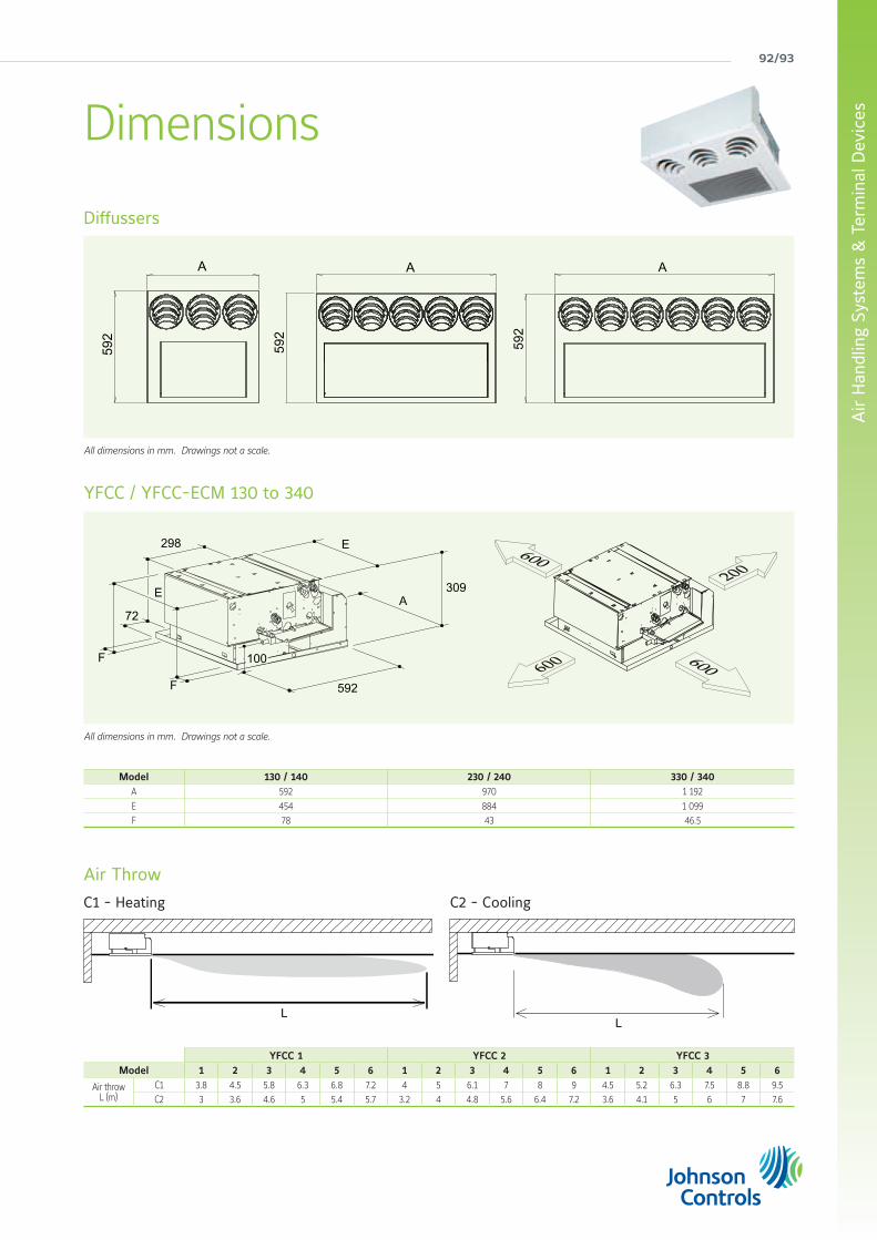
92/93
Air
Han
dlin
g Sy
stem
s &
Ter
min
al D
evic
es
All dimensions in mm. Drawings not a scale.
All dimensions in mm. Drawings not a scale.
Diffussers
YFCC / YFCC-ECM 130 to 340
Air Throw
C1 - Heating C2 - Cooling
Dimensions
A
592
A59
2A
592
72
298
309
592
E
A
F
F
E
100
Model 130 / 140 230 / 240 330 / 340A 592 970 1 192
E 454 884 1 099F 78 43 46.5
YFCC 1 YFCC 2 YFCC 3Model 1 2 3 4 5 6 1 2 3 4 5 6 1 2 3 4 5 6
Air throwL (m)
C1 3.8 4.5 5.8 6.3 6.8 7.2 4 5 6.1 7 8 9 4.5 5.2 6.3 7.5 8.8 9.5C2 3 3.6 4.6 5 5.4 5.7 3.2 4 4.8 5.6 6.4 7.2 3.6 4.1 5 6 7 7.6
LL

york air-conditioning products
Wired control (YHMY)• 4 operation modes (Cool/Heat/Auto/Fan)
• Room temperature and setting
• Fan speed selector
(Auto, low, medium and high)
Infrared control (YHMH)• Wireless
• 5 operation modes (Cool/Heat/Auto/Dry/Fan)
• Sleep Mode
• Room Temperature setting
• Fan speed selection
• Timer
• Air flow direction setting
• LCD display
Features• Wired control or infrared control
• Automatic air sweep
• 3 way valves fitted (YHMH 20V and 30V
models) or 2 way valves supplied loose in
all range
• Condensate collection tray
• Air filter included
• Heat exchange coil
TR. Wired ControlRemote three speeds controller, electronic thermostat and Summer/Winter switch
ATR. Wired ControlAutomatic TR
2 Way Valve ON/OFF with thermoelectric actuator.Suitable for the connection with Ø 12 mm pipes
Rear Framefor installation of valves (accessorie)
Electronic Infrared Control
FX03 Terminal unit controllerBacNET and N2 Metasys network compatible
YHM Hydro High Wall2 pipe systemA range from 1.7 to 4.7 kW
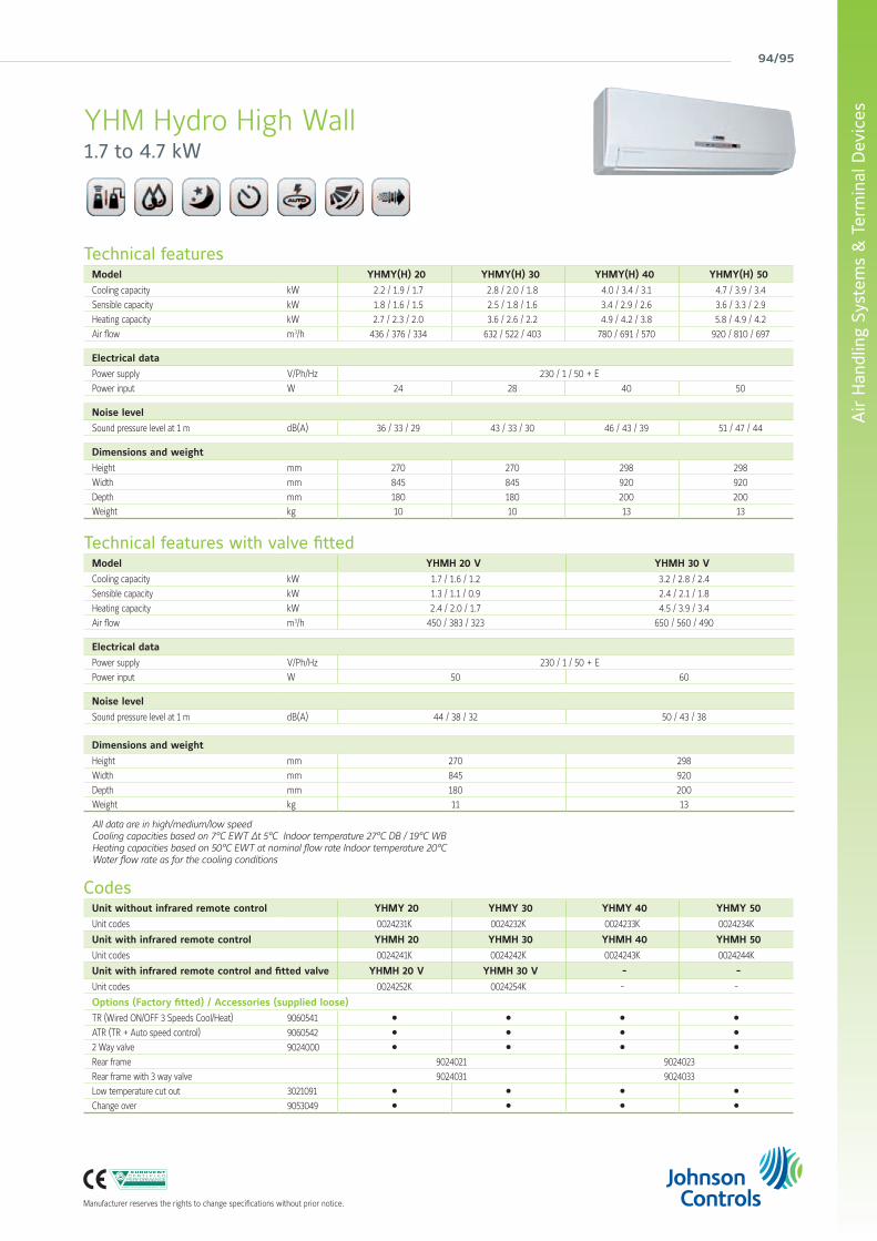
94/95
Air
Han
dlin
g Sy
stem
s &
Ter
min
al D
evic
es
Manufacturer reserves the rights to change specifications without prior notice.
Technical featuresModel YHMY(H) 20 YHMY(H) 30 YHMY(H) 40 YHMY(H) 50
Cooling capacity kW 2.2 / 1.9 / 1.7 2.8 / 2.0 / 1.8 4.0 / 3.4 / 3.1 4.7 / 3.9 / 3.4
Sensible capacity kW 1.8 / 1.6 / 1.5 2.5 / 1.8 / 1.6 3.4 / 2.9 / 2.6 3.6 / 3.3 / 2.9
Heating capacity kW 2.7 / 2.3 / 2.0 3.6 / 2.6 / 2.2 4.9 / 4.2 / 3.8 5.8 / 4.9 / 4.2
Air flow m3/h 436 / 376 / 334 632 / 522 / 403 780 / 691 / 570 920 / 810 / 697
Electrical data
Power supply V/Ph/Hz 230 / 1 / 50 + E
Power input W 24 28 40 50
Noise level
Sound pressure level at 1 m dB(A) 36 / 33 / 29 43 / 33 / 30 46 / 43 / 39 51 / 47 / 44
Dimensions and weight
Height mm 270 270 298 298
Width mm 845 845 920 920
Depth mm 180 180 200 200Weight kg 10 10 13 13
Technical features with valve fittedModel YHMH 20 V YHMH 30 V
Cooling capacity kW 1.7 / 1.6 / 1.2 3.2 / 2.8 / 2.4
Sensible capacity kW 1.3 / 1.1 / 0.9 2.4 / 2.1 / 1.8
Heating capacity kW 2.4 / 2.0 / 1.7 4.5 / 3.9 / 3.4
Air flow m3/h 450 / 383 / 323 650 / 560 / 490
Electrical data
Power supply V/Ph/Hz 230 / 1 / 50 + E
Power input W 50 60
Noise level
Sound pressure level at 1 m dB(A) 44 / 38 / 32 50 / 43 / 38
Dimensions and weight
Height mm 270 298
Width mm 845 920
Depth mm 180 200Weight kg 11 13
All data are in high/medium/low speedCooling capacities based on 7°C EWT ∆t 5°C Indoor temperature 27°C DB / 19°C WB Heating capacities based on 50°C EWT at nominal flow rate Indoor temperature 20°CWater flow rate as for the cooling conditions
CodesUnit without infrared remote control YHMY 20 YHMY 30 YHMY 40 YHMY 50
Unit codes 0024231K 0024232K 0024233K 0024234K
Unit with infrared remote control YHMH 20 YHMH 30 YHMH 40 YHMH 50
Unit codes 0024241K 0024242K 0024243K 0024244K
Unit with infrared remote control and fitted valve YHMH 20 V YHMH 30 V - -
Unit codes 0024252K 0024254K - -
Options (Factory fitted) / Accessories (supplied loose)
TR (Wired ON/OFF 3 Speeds Cool/Heat) 9060541 l l l l
ATR (TR + Auto speed control) 9060542 l l l l
2 Way valve 9024000 l l l l
Rear frame 9024021 9024023
Rear frame with 3 way valve 9024031 9024033
Low temperature cut out 3021091 l l l l
Change over 9053049 l l l l
YHM Hydro High Wall1.7 to 4.7 kW

york air-conditioning products
YORK® Close Control unitsMaintaining a constant temperature, purity and humidity of air is essential for ensuring a stable environment for critical electronic and computer equipment, this is why there is the need for close control air conditioning. Unlike comfort air conditioning, close control systems must operate constantly 24/7 requiring high reliability and minimal power consumption. Johnson Controls knows that no two close control requirements are the same, this is why the YORK® range of custom close control units offers quiet, compact and energy efficient equipment that can be configured to needed requirements.

96/97
Air
Han
dlin
g Sy
stem
s &
Ter
min
al D
evic
es
Manufacturer reserves the rights to change specifications without prior notice.
An extensive offering • cooling capacities of up to 220kw (chilled water) or 100kw (direct expansion) with optional free cooling models. Up flow or down flow configuration, either as self-contained packaged units or suitable for connection to remote condensers, are also available
• optional direct expansion units fitted with scroll compressors, which have much lower noise and energy consumption than reciprocating compressors
• R410a refrigerant units available
• optional Free Cooling coil to reduce energy consumption required through use of mechanical cooling
• plug fan with Electronically Commuted ‘EC’ fans option, to allow fully modulating control of airflow
• low component face velocities, for a lower total pressure drop and reduced energy consumption
• minimised dimensions, enabling one of the market’s greatest ratios between sensible cooling capacity and base foot print

york air-conditioning products
YORK® YC-P SeriesClose Control Air ConditionersA complete range from 6.6 kW up to 200 kW
High energy efficiency and minimum environmental impact“P” Series air conditioners for close control applications are specialised machines with design and operating features which clearly differentiate them from standard air conditioning units.
The “P” Series air conditioners offer very high energy efficiency values in all operating conditions which translates into less CO
2
emissions and particularly low running costs. Though optimised for use in data centers and telephone exchanges, they are equally valid in special applications such as measurement laboratories, TV recording studios, museums, control rooms for electricity power stations and railway junctions and other areas where there are prevalent sensible thermal loads and crowding is negligible.
Their application is also ideal in widely varied industrial sectors: optics, electronics, electromedical equipment, electronic equipment production, musical instrument production etc.
Optimal efficiency
Johnson Controls’ “P” Series design offers the highest sensible cooling capacity with the minimum footprint possible, which translates into optimal ratio levels of cooling capacity to footprint area. This is an important feature in reducing the space needed by machinery, allowing more room in the space for IT equipment. This advantage is especially important given the progressive increases in capacity required by data centers and other computer applications which, over time, need the addition of extra air conditioners.
Clean efficiency is also ensured by the use of the R-410A refrigerant, respectful to the ozone layer.
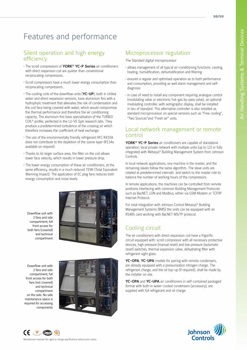
98/99
Air
Han
dlin
g Sy
stem
s &
Ter
min
al D
evic
es
Manufacturer reserves the rights to change specifications without prior notice.
Silent operation and high energy efficiency• The scroll compressors of YORK® YC-P Series air conditioners with direct expansion coil are quieter than conventional reciprocating compressors.
• Scroll compressors have a much lower energy consumption than reciprocating compressors.
• The cooling coils of the downflow units (YC-UP), both in chilled water and direct expansion versions, have aluminium fins with a hydrophylic treatment that alleviates the risk of condensation and the coil face being covered with water, which would compromise the thermal performance and therefore the air conditioning capacity. The aluminum fins have specialisation of the TURBO/COIL® profile, perfected in the LU-VE SpA research labs. They produce a predetermined turbulence of the crossing air which therefore increases the coefficient of heat exchange.
• The use of the environmentally friendly refrigerant HFC R410A does not contribute to the depletion of the ozone layer (R134a available on request).
• Thanks to its larger surface area, the filter on the coil allows lower face velocity, which results in lower pressure drop.
• The lower energy consumption of these air conditioners, at the same efficiency, results in a much reduced TEWI (Total Equivalent Warming Impact). The application of EC plug fans reduces both energy consumption and noise levels.
Downflow unit with 2 fans and side
compartment; full front access for
both fans (covered) and technical compartment
Downflow unit with 2 fans and side
compartment; full front access for both
fans (not covered) and technical compartment
on the side. No side maintanance space is required for accessing
components
Microprocessor regulationThe Standard digital microprocessor
• allows management of all typical air-conditioning functions: cooling, heating, humidification, dehumidification and filtering
• ensures a regular and optimised operation as to both performance and consumption, providing as well alarm management and self-diagnosis
• in case of need to install any component requiring analogue control (modulating valve or electronic hot-gas by-pass valve), an optional modulating controller, with semigraphic display, shall be installed in lieu of standard. This alternative controller is also installed as standard microprocessor on special versions such as “Free cooling”, “Two Sources”and “Fresh air” units.
Local network management or remotecontrolYORK® YC-P Series air conditioners are capable of standalone operation, local private network with multiple units (up to 12) or fully integrated with Metasys® Building Management System from Johnson Controls.
In local network applications, one machine is the master, and the remaining slaves follow the same algorithm. The slave units are rotated at predetermined intervals and switch to the master role to balance the number of working hours of the compressors.
In remote applications, the machines can be controlled from remote positions interfacing with common Building Management Protocols such as BacNET, LON and Modbus, either via GSM Modem or TCP/IP Internet Protocol.
For total integration with Johnson Control Metasys® Building Management Systems (BMS) the units can be equipped with an RS485 card working with BacNET MS/TP protocol.
Cooling circuitThe air conditioners with direct expansion coil have a frigorific circuit equipped with: scroll compressor with all necessary protective devices, high pressure (manual reset) and low pressure (automatic reset) switches, thermal expansion valve, dehydrating filter with refrigerant sight glass.
YC-OPA, YC-UPA models for pairing with remote condensers, are already equipped with a pressurisation nitrogen charge. The refrigerant charge, and the oil top-up (if required), shall be made by the installer on site.
YC-OPA and YC-UPA air conditioners in self-contained packaged format with built-in water-cooled condensers (accessory), are supplied with full refrigerant and oil charge.
Features and performance

york air-conditioning products
Control PanelAll the units are equipped with a complete control panel with main isolator switch. Magnetothermic switches, contactors, and all necessary protection is provided, as required by legal codes and standards.
The control panel of the units equipped with compressors (“A” as third letter of the identification code) has as standard a phase sequencer, which prevents the compressor from getting damaged when counter running. Also, the control panel has two spare terminals for remote indication of a cumulative alarm, as well as two terminals for starting up and stopping the unit from remote position.
The control panel does not include the fan speed controller(s) for the fans of the air cooled remote condensers (winter control). This device is included as standard in the CEA and CEA/LN air cooled condensers from Johnson Controls.
Should you decide to match the unit with a condenser from another manufacturer, the controller(s) can be ordered as accessory.
Electronic expansion valve (*)Electronic expansion valves are one of the most recent pieces of equipment that enable us to improve the energy efficiency at partial loads of direct expansion machines. These valves are installed at the inlet of the evaporator, substituting the traditional thermostatic expansion ones: this allows more precise control of the quantity of refrigerant entering the evaporator, and guarantees good capacity regulation, typically between 100% and 50%. Electronic expansion valves also allows control of the amount of overheated gas at the outlet of the evaporator, thus allowing a significant reduction of the condensation pressure during winter or night-time operation whilst maintaining the evaporation pressure unchanged. Adoption of the electronic expansion valve (optional) guarantees a significant increase of the EER values.
One or two completely independentcompressorsModels with “1” as the last digit of the unit model number have a single circuit and a single compressor. Those with “2” as the last digit on the other hand have two completely independent refrigerant circuits and two compressors.
The circuits are fitted with all the safety and regulation devices necessary for efficient and reliable operation.
The evaporator coil can be single or double circuit depending on the number of compressors.
Hydraulic circuitAir conditioners with chilled water coil, YC-OPU and YC-UPU, include a finned coil and a three-way throttling motorised valve for water flow regulation. The hydraulic circuit is provided with copper tubes with anti-condensate insulation. The coils are optimised for both water with a temperature of 7/12 and for higher ones such as 15/20.
The standard throttling valve (3 points) allows good modulation of the cooling capacity as a function of the environmental conditions, especially with constant thermal loads.
Modulating regulation of the cooling capacity (**)If a very precise regulation and high response speed are required, a modulating valve (optional) can be installed in lieu of the throttling one. The installation of this valve is recommended in case of functionment with a lot of fresh air. However, the modulating valve needs an analogue signal, not digital, so the installation of the optional modulating controller is necessary.
Large surface filtersThe units are equipped with self-extinguishing media class G4 filters. The filters are installed inclined before the cooling coil in order to offer a larger surface and allow lower air crossing speeds, with lower energy consumption.
A 450 mm high duct (accessory) can be installed for holding a F7 class filter, vertically on supply air discharge.
Design suitable to civil environmentsYORK® YC-P Series air conditioners have a pleasant and functional design, suitable for installation in civil environments. Their structure consists of aluminium profiles and closing panels hinged on them. Both panels and profiles are coated with a dark grey PVC layer (anthracites), thermoacoustically insulated by polyurethane layer, and further coated with an anti scratch plastic film.
Two versions are available for up flow units (YC-OP): front grille & top air discharge (standard), or blind front panel, suction from the bottom and top discharge (optional).
Modulating controller display and keypad
(*) units equipped with frigorific circuit(**) units equipped with chilled water coil

100/101
Air
Han
dlin
g Sy
stem
s &
Ter
min
al D
evic
es
Standard fansThe standard fan section is made up by one or more backward curved, free running impeller, radial fans (plug fan) with single speed motors which offer a particularly low noise level as well as a high efficiency. The free running impeller assures a very high efficiency and an easy cleaning of the blades too.
These fans offer a high available static pressure, perfect for most applications. The final air flow comes as a consequence of the real pressure drop of the installation; anyhow it can be calculated through our selection software.
Standard fans with AC motors have two operating speeds and therefore two different airflows and static pressures, which can be selected through their terminal strip cabling.
Electronically commutated fans (EC) for a perfect air flow regulationPlug fans, made up by one or more backward curved, free running impeller, radial fans, offer several advantages:
- particularly silent operation;
- extremely high performance;
- easy cleaning of the blades.
Plug fans factory fitted with EC (electronically commutated) constant current brushless motors with external rotors are the latest innovation in energy saving when it comes to the fan sector. They are about 25-30% more efficient than traditional asynchronous alternating current motors. They also allow continuous speed variation depending on the external sensor signal on the microprocessor control of the machine, without the need for an inverter or other electronic devices.
At equal operating conditions, the combination of EC motors and plug fans therefore offers several advantages:
- better functionality;
- improved energy efficiency;
- lower sound level;
- absence of vibration in operation and soft start (lower absorbed current on starting).
Regulation OptionsJohnson Controls provides four different alternatives for the regulation of the airflow of the EC fans depending on the requirements of the installation:
1. Constant fan rotation speed. The available high static pressure is ideal for most applications. The effective air flow depends on the real pressure drop of the aeraulic system of the installation, however it can be calculated through Johnson Controls computerised selection program.
2. Constant airflow independent of the pressure drop of the filters. In order to maintain a constant airflow, an internal sensor guides the microprocessor management system to vary the airflow handled by the fan, depending on the degree of clogging of the filters. This ensures that insufficient cooling does not occur due to reduced airflow arising from dirty filters.
3. Variable airflow depending on the cooling capacity required by the installation. This is the classic VAV (Variable Air Volume) plant arrangement which responds to increased demand by a proportionate increase in airflow and vice versa. This type of plant offers interesting energy advantages at partial loads, which occur extensively throughout the year, especially at night.
4. Airflow as a function of pressure in the raised floor. This regulation alternative is envisaged for plants with raised floors where the air is distributed under the floor itself. The microprocessor management system maintains constant under-floor pressure. In particular, in very large areas subdivided into multiple local zones with partition dampers driven by individual thermostats, constant regulation of the pressure is necessary to avoid imbalances in the distribution of the air.
Fan section
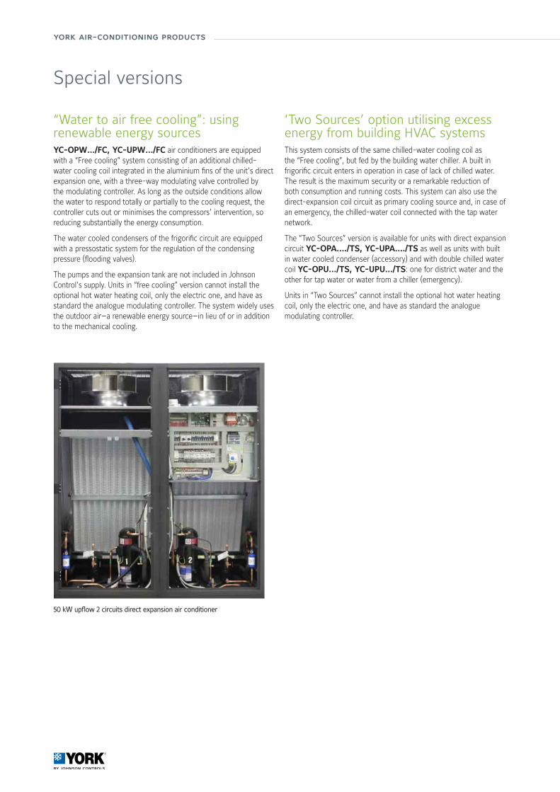
york air-conditioning products
“Water to air free cooling”: using renewable energy sourcesYC-OPW…/FC, YC-UPW…/FC air conditioners are equipped with a “Free cooling” system consisting of an additional chilled-water cooling coil integrated in the aluminium fins of the unit’s direct expansion one, with a three-way modulating valve controlled by the modulating controller. As long as the outside conditions allow the water to respond totally or partially to the cooling request, the controller cuts out or minimises the compressors’ intervention, so reducing substantially the energy consumption.
The water cooled condensers of the frigorific circuit are equipped with a pressostatic system for the regulation of the condensing pressure (flooding valves).
The pumps and the expansion tank are not included in Johnson Control’s supply. Units in “free cooling” version cannot install the optional hot water heating coil, only the electric one, and have as standard the analogue modulating controller. The system widely uses the outdoor air—a renewable energy source—in lieu of or in addition to the mechanical cooling.
‘Two Sources’ option utilising excess energy from building HVAC systemsThis system consists of the same chilled-water cooling coil as the “Free cooling”, but fed by the building water chiller. A built in frigorific circuit enters in operation in case of lack of chilled water. The result is the maximum security or a remarkable reduction of both consumption and running costs. This system can also use the direct-expansion coil circuit as primary cooling source and, in case of an emergency, the chilled-water coil connected with the tap water network.
The “Two Sources” version is available for units with direct expansion circuit YC-OPA…./TS, YC-UPA…./TS as well as units with built in water cooled condenser (accessory) and with double chilled water coil YC-OPU…/TS, YC-UPU…/TS: one for district water and the other for tap water or water from a chiller (emergency).
Units in “Two Sources” cannot install the optional hot water heating coil, only the electric one, and have as standard the analogue modulating controller.
Special versions
50 kW upflow 2 circuits direct expansion air conditioner
102/103
Air
Han
dlin
g Sy
stem
s &
Ter
min
al D
evic
es
Numerous accessories and options are available for the “P” Series air conditioners to personalise the installation depending on the requirements of the plant and its design. Divided by function, they include:
Free cooling or two sources
• Additional Free cooling circuit.• Additional Two sources circuit.
Alarms
• Water alarm (supplied loose).• Out-of-range air discharge temperature alarm.• Smoke/fire alarm terminals.
Water cooled condensers and pressostatic valves
• Welded stainless steel water cooled plate condenser.• 2 way pressostatic valve (only if the water condenser is selected).
Sound proofing devices
• Sound damped duct for air suction or discharge (h=550 mm). Allows a reduction of approx 4 dB(A) of the SPL of the unit.
• Double layer sound damping panels. Reduces SPL by approx 2 dB(A) in upflow units (OP series), and approx.4 dB(A) in downflow units ((UP series).
• Double-layer “sandwich” thermo-acoustic insulation panels.
Panels and base
• Blind front panel (OP) and open base for bottom air intake.• Front panel with grille in the lower part (UP) and closed base.
Plenum
• Plenum (h=550 mm) for air discharge or intake with front grille.• Plenum (h=550 mm) for air discharge or intake with front and side grilles.
Direct expansion unit cooling capacity regulation
• Electronic expansion valve.• Electronic hot-gas injection system for the regulation of cooling capacity (100-10%).
Heating, reheating and humidification
• Single-step or double-step low thermal inertia electrical heating/reheating coil.
• Immersed-electrode modulating humidifier and dehumidification control.
• Humidity sensor for the single control of dehumidification.
Boards and sensors
• Humidity sensor and board for external humidification control not supplied by Johnson Controls.
• RS 485 communication board.
Dampers
• Gravity-operated overpressure dampers on the air outlet (OP series).
• Motorised overpressure dampers on the air intake (UP series).
Under bases
• Adjustable under base (OP only). (Precise height to be specified with order).
• Adjustable under base with air deflector (UP only). (Precise height to be specified with order).
Fans and filters
• Electronic EC fans with incorporated inverter for constant rotation speed regulation.
• Electronic EC fans with incorporated inverter for the regulation of air flow in relation to the required cooling capacity.
• Electronic EC fans with incorporated inverter for the regulation of constant pressure in the raised floor.
• Electronic two-speed AC fans.• F7 filter to be installed on the air intake as substitute for the standard G4.
• Monophase condenser-fan rotation speed variator
Fittings and accessories

york air-conditioning products
Technical Characteristics
YC-OPA: direct expansion air conditioners with air cooled or water condensers and up-flow air supply
Models 71 111 141 211 251 301 302 372 361 461 422 512 612 662 852 932
Performances
Total cooling capacity kW 7.2 11.2 14.3 20.9 25.2 30.4 30.6 38.2 33.8 47.2 42.2 51.2 64.3 67.5 84.3 96.0
Sensible cooling capacity kW 6.7 10.6 11.8 19.8 21.7 29.4 27.7 31.0 31.5 46.2 41.5 45.0 58.2 59.8 67.3 83.5
Airflow m3/h 2200 3200 3200 7000 7000 8700 8700 8700 14500 14500 14500 14500 17900 17900 17900 22500
EER 3.09 3.11 3.15 3.12 3.05 3.10 3.18 2.96 2.55 3.38 3.12 3.06 3.21 3.11 3.14 3.41
Sound pressure level dB(A) 49 49 49 56 56 58 58 58 63 63 63 63 68 68 68 69
Dimensions & weight
Lenght mm 750 750 750 860 860 750 1410 1410 1750 1750 1750 1750 2300 2300 2300 2640
Depth mm 630 630 630 880 880 880 880 880 880 880 880 880 880 880 880 880
Height mm 1990 1990 1990 1990 1990 1965 1990 1990 1990 1990 1990 1990 990 990 990 1990
Net weight kg 170 170 170 210 270 270 300 315 330 400 420 440 420 490 315 330
* The performances are referred to: refrigerant R410; condensing temperature: 45°C; inlet air: 24°C - 45% RH; for chilled water: 7/12°C;The SPL is referred to 2 m distance, 1,5 m height, free field and sound damped discharge mouth. Available static pressure: 30 Pa.EER = Electro Efficiency Ratio = Total cooling capacity / Compressors + fans + condensers fans power input.The above performances don’t consider the heat generated by the fans which must be added to the thermal load of the system.
Technical Characteristics
YC-UPA: direct expansion air conditioners with air cooled or water condensers and down-flow air supply
Models 71 111 141 211 251 301 302 372 361 461 422 512 612 662 852 932
Performances
Total cooling capacity kW 7.2 11.2 14.3 20.9 25.2 30.4 30.6 38.2 33.8 47.2 42.2 51.2 64.3 67.5 84.3 96.0
Sensible cooling capacity kW 6.7 10.6 11.8 19.8 21.7 29.4 27.7 31.0 31.5 46.2 41.5 45.0 58.2 59.8 67.3 83.5
Airflow m3/h 2200 3200 3200 7000 7000 8700 8700 8700 14500 14500 14500 14500 17900 17900 17900 22500
EER 3.09 3.11 3.15 3.12 3.05 3.10 3.18 2.96 2.55 3.38 3.12 3.06 3.21 3.11 3.14 3.41
Sound pressure level dB(A) 49 49 49 56 56 58 58 58 63 63 63 63 68 68 68 69
Dimensions & weight
Lenght mm 750 750 750 860 860 750 1410 1410 1750 1750 1750 1750 2300 2300 2300 2640
Depth mm 630 630 630 880 880 880 880 880 880 880 880 880 880 880 880 880
Height mm 1990 1990 1990 1990 1990 1965 1990 1990 1990 1990 1990 1990 990 990 990 1990
Net weight kg 170 170 170 210 255 270 300 315 330 400 420 440 420 470 315 330
* The performances are referred to: refrigerant R410; condensing temperature: 45°C; inlet air: 24°C - 45% RH; for chilled water: 7/12°C;The SPL is referred to 2 m distance, 1,5 m height, free field and sound damped discharge mouth. Available static pressure: 30 Pa.EER = Electro Efficiency Ratio = Total cooling capacity / Compressors + fans + condensers fans power input.The above performances don’t consider the heat generated by the fans which must be added to the thermal load of the system.
Performance at JOHNSON CONTROLS test conditions*
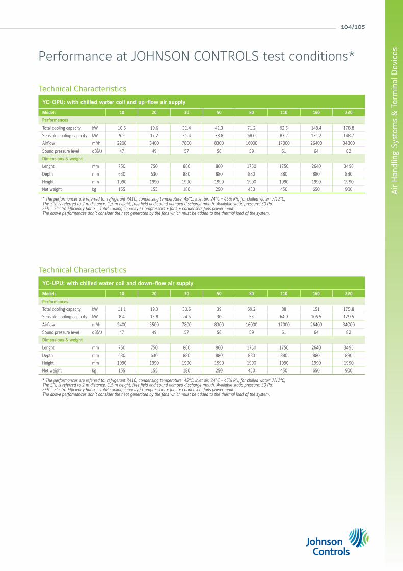
104/105
Air
Han
dlin
g Sy
stem
s &
Ter
min
al D
evic
es
Technical Characteristics
YC-OPU: with chilled water coil and up-flow air supply
Models 10 20 30 50 80 110 160 220
Performances
Total cooling capacity kW 10.6 19.6 31.4 41.3 71.2 92.5 148.4 178.8
Sensible cooling capacity kW 9.9 17.2 31.4 38.8 68.0 83.2 131.2 148.7
Airflow m3/h 2200 3400 7800 8300 16000 17000 26400 34800
Sound pressure level dB(A) 47 49 57 56 59 61 64 82
Dimensions & weight
Lenght mm 750 750 860 860 1750 1750 2640 3496
Depth mm 630 630 880 880 880 880 880 880
Height mm 1990 1990 1990 1990 1990 1990 1990 1990
Net weight kg 155 155 180 250 450 450 650 900
* The performances are referred to: refrigerant R410; condensing temperature: 45°C; inlet air: 24°C - 45% RH; for chilled water: 7/12°C;The SPL is referred to 2 m distance, 1,5 m height, free field and sound damped discharge mouth. Available static pressure: 30 Pa.EER = Electro Efficiency Ratio = Total cooling capacity / Compressors + fans + condensers fans power input.The above performances don’t consider the heat generated by the fans which must be added to the thermal load of the system.
Technical Characteristics
YC-UPU: with chilled water coil and down-flow air supply
Models 10 20 30 50 80 110 160 220
Performances
Total cooling capacity kW 11.1 19.3 30.6 39 69.2 88 151 175.8
Sensible cooling capacity kW 8.4 13.8 24.5 30 53 64.9 106.5 129.5
Airflow m3/h 2400 3500 7800 8300 16000 17000 26400 34000
Sound pressure level dB(A) 47 49 57 56 59 61 64 82
Dimensions & weight
Lenght mm 750 750 860 860 1750 1750 2640 3495
Depth mm 630 630 880 880 880 880 880 880
Height mm 1990 1990 1990 1990 1990 1990 1990 1990
Net weight kg 155 155 180 250 450 450 650 900
* The performances are referred to: refrigerant R410; condensing temperature: 45°C; inlet air: 24°C - 45% RH; for chilled water: 7/12°C;The SPL is referred to 2 m distance, 1,5 m height, free field and sound damped discharge mouth. Available static pressure: 30 Pa.EER = Electro Efficiency Ratio = Total cooling capacity / Compressors + fans + condensers fans power input.The above performances don’t consider the heat generated by the fans which must be added to the thermal load of the system.
Performance at JOHNSON CONTROLS test conditions*

york air-conditioning products
SmartPac
Site Fitted Manufacturer Factory Fitted “SmartPac”
Wiring & Installation
Control Panel
Commissioning
Engineering
Controls
100%
90%
80%
70%
60%
50%
40%
30%
20%
10%
0%
SmartPac from Johnson Controls offers factory packaged control solutions that reduce cost, enhance quality and optimise site time.
Once on site, the equipment can be started immediately. Commissioning time is dramatically reduced, allowing to better control the project costs through simplifying equipment installation and commissioning.
Quality is ensured through application and testing to European Installation regulations at the factory. Pre-installed software is configured to deliver air at the specified volume, temperature and humidity.

106/107
Air
Han
dlin
g Sy
stem
s &
Ter
min
al D
evic
es
Manufacturer reserves the rights to change specifications without prior notice.
SmartPac and YORK® Air Handling unitsThe Air Handling Unit arrives on site ready to connect to the site network, and final commission is simplified through the unit’s keypad and display.
Panel Power wiring, controls wiring, Variable Speed Drive, pre-engineered controller and required peripheral devices are all supplied, factory fitted and tested.
SmartPac and YORK® Fan Coil unitsYORK® Fan Coil Units are available with factory packaged controls and numerous options for controllers and valves to allow reduced installation time on site.
Either EUBAC approved or alternative configurable controllers are offered, and a choice of BACNet, N2 Open or LON communication options is no extra cost. Valve requirements can also be met with a wide range of modulating and on/off actuators and isolation valves available and factory fitted.
SmartPac and YORK® Standard Control panelWith a standardized design the YORK® Airside Equipment is a cost effective solution. Furthermore, Variable Speed Drives give extra efficiency communicating the Johnson controller in either full native BACNet or LON or N2 protocols allowing seamless communication with existing control systems.
SmartPac and YORK® Roof Top & Close Control unitsFactory packaged controls’ solution enable, to dramatically reduce on-site commissioning costs. Both are delivered to site with pre-installed controls, factory tested and ready to apply the power.
york air-conditioning products
roomtop
rooftop
large split
Packaged Equipment& Large Split Systems
108/109

york air-conditioning products
The YKlon is a controller regulating all components and accessories. It will pro actively manage cool and heat stages to maintain a stable room temperature maximizing the efficiency. Additionally, the benefits are:• Redundancy on cool and heat stages (if one step is locked out, the PCB starts another one automatically).• Random start between units to minimise electrical tariff.• All stages will start in sequence to reduce peak inrush.• Reduces nuisance calls by using 3 times “you are out” on all safeties before a hard lockout occurs.• Automatic restart after power failure. Compressors run time priority.• Alarm output relay and led diagnostic code. No parameters to check before starting.• Lockout and incident level of protection. Last 10 lockouts stored in a non-volatile memory.• 4 heating stages on hot water heating.• BMS connection (N2 Open protocol).
The Yktool is the perfect tool to use on a regular basis for comissioning and service on site. For comissioning, it will override the thermostat and start the cooling or heating stages. Being a plug and play device, you will have direct acess to all sensors and status of each components and accessories installed (lockout & incidents, temperatures, defrost test...).
Code: S613786031
Control System
YKN2open
YKtool N2open

Pack
aged
Equ
ipm
ent
& L
arge
Spl
it S
yste
ms
110/111
Indoor remote probe to provide close control of the ambient temperature at a location away from the DPC-1 and DPC-1R thermostats.
Code: S603786042
Digital remote probe to provide close control of the ambient temperature at a location away from DPC-1 and DPC-1R thermostats. Up to 4 remote probes can be connected to make an average of the room conditioned.
Code: S603786049
Remote probe to provide close control of the return air temperature in the duct, at a location away from DPC-1 and DPC-1R thermostats. The use of this probe is recommended when an indoor remote probe cannot be installed in the area where temperature is to be controlled.
Code: S603786047
• Day (normal), night (economy) and unoccupied (stand by).
• Lockout code on screen gives direct diagnostics.
• ON/OFF or programmable from dip switch setting.
• Day or night programmable state avoids wide internal temperature variation.
• 3 preset and 3 programmable profiles.
• Temperature override.• Select the control sensor you want to use (integrated in the thermostat, return air in duct or room sensor).
• Turbo, normal or economy logic from dip switch setting.
• From –3°C to +3°C sensor offset.• Average temperature with room or duct sensors.
Thermostat DPC-1
Main featuresStrategy Turbo, normal or economyAuto restart after power failure l l
Number of cool stages 2 1 2Number of heat stages 2 1 2Auxiliary Heat l l
Automatic Heat/Cool change over l l
Continuous or auto indoor fan l l
Manual setback (Day/Night key) Day, night and unocuppiedOverride possibility l l
Compressor anti short cycle l l
°C Range cooling / heating 10 to 32°C / 9 to 32°CProgrammable, 7-day l l
Lockout codes l l
Outdoor air temperature l with YKlonSensor selection l l
X : Delivered as standard with the unit. X (1) : Standard but has to be ordered separately. O : Optional. l : Function available.
Thermostat models DPC-1 DPC-1RCode S603786044 S603786045
Roomtop RTC and RTH X 0Rooftop All models X (1) 0
Split systemVAC and VAH X 0VCH X 0
Thermostats with integrated sensors
Room sensor
Ambiance sensor
Duct sensor
DS-1
AS-1
RS-1
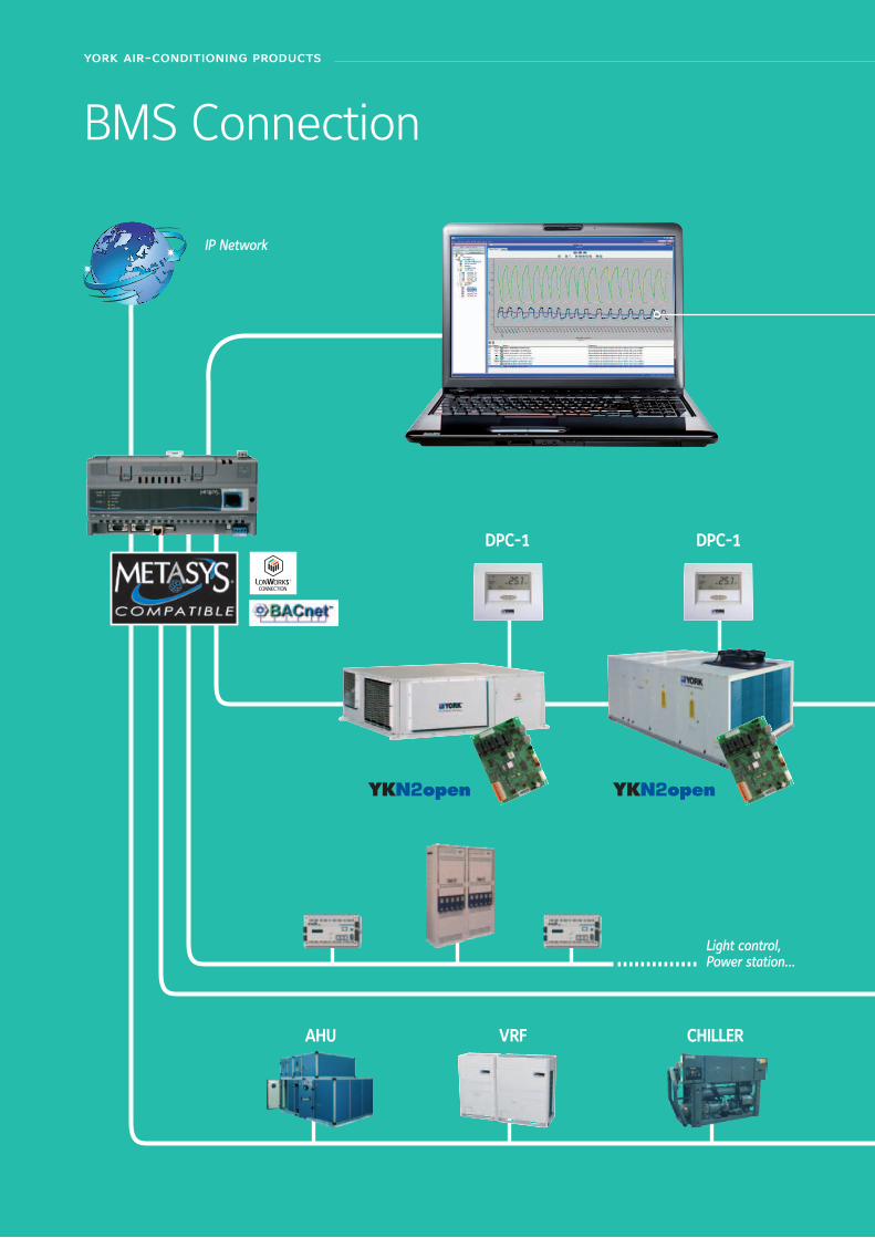
york air-conditioning products
IP Network
DPC-1
YKN2open
DPC-1
YKN2open
york air-conditioning products
BMS Connection
Light control,Power station...
CHILLERVRFAHU
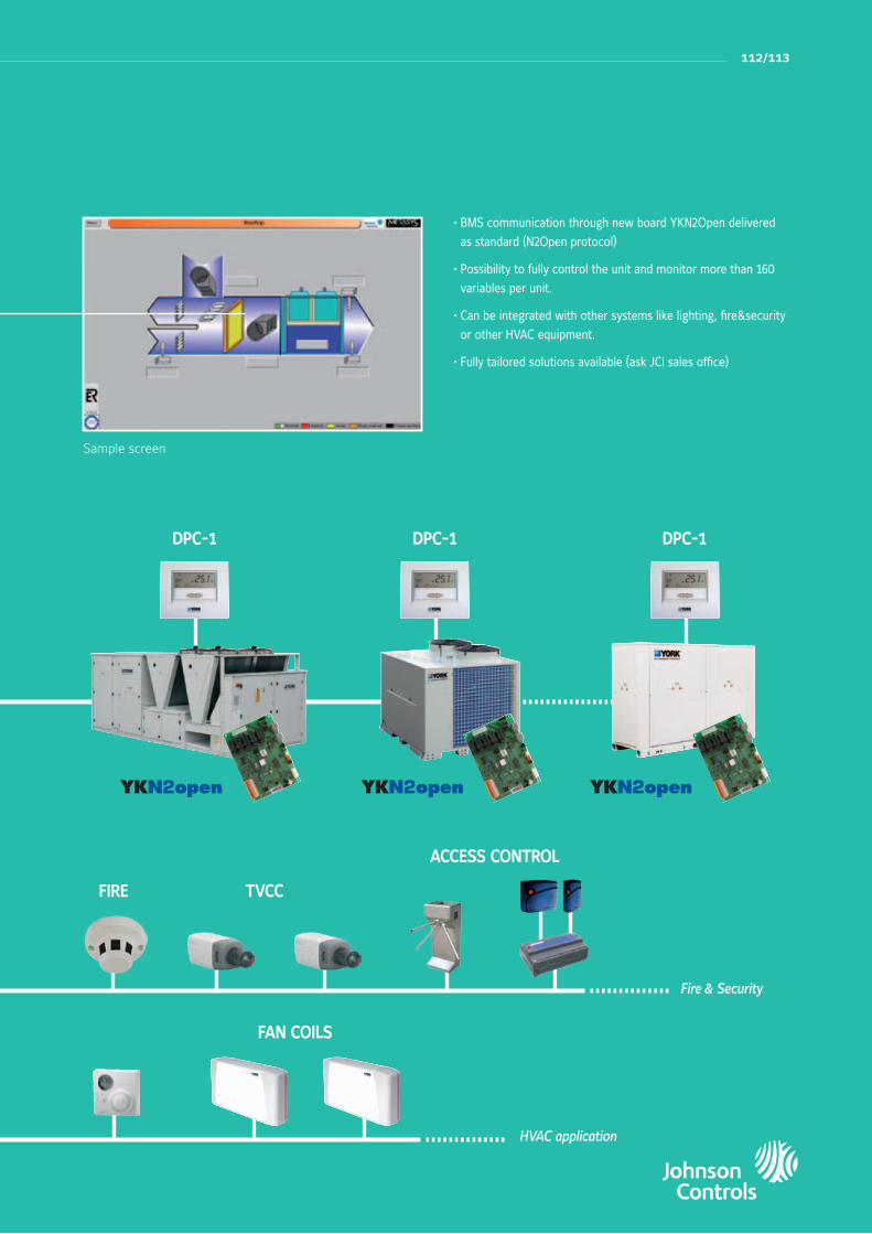
Pack
aged
Equ
ipm
ent
& L
arge
Spl
it S
yste
ms
112/113
Sample screen
• BMS communication through new board YKN2Open delivered
as standard (N2Open protocol)
• Possibility to fully control the unit and monitor more than 160
variables per unit.
• Can be integrated with other systems like lighting, fire&security
or other HVAC equipment.
• Fully tailored solutions available (ask JCI sales office)
DPC-1 DPC-1 DPC-1
YKN2open YKN2open YKN2open
112/113
Fire & Security
HVAC application
FAN COILS
FIRE TVCC
ACCESS CONTROL

york air-conditioning products
RoomtopRTC-RTH - LA complete range from 14.6 kW up to 27.0 kW
Features• New YKN2open board • Possibility to be installed outdoor• Scroll Compressors• High COP and EER• 1/4 turn on electrical panel• Expansion valves for models 20, 25 and 30• High external static pressure on evaporator and condenser
• Digital thermostat DPC-1 and indoor air filter included
Summer RTC-RTH Winter RTH
Outdoor air Outdoor airIndoor air Indoor air
Compressor Compressor
4 ways valveCondenser
Evaporator
Standard air flow Site modification
L = version
Capacity range:15 = 15 kW
Product category:RTC = Cooling onlyRTH = Heat pump
RTC 15 L Nomenclature
YKN2open

Pack
aged
Equ
ipm
ent
& L
arge
Spl
it S
yste
ms
Manufacturer reserves the rights to change specifications without prior notice.
114/115
RoomtopRTC-RTH 15 to 30 - L
Compatibility table / Codes
Cooling only models RTC 15 L RTC 20 L RTC 25 L RTC 30 L
S661211545 S661212081 S661212545 S661213045
Heat pump modelsRTH 15 L RTH 20 L RTH 25 L RTH 30 L
S662051544 S662052054 S662052545 S662053045
Thermostat
Delivered as standard with the unit DPC-1
Accessoriesor options Remarks Code
RTC 15 L RTC 20 L RTC 25 L RTC 30 L
RTH 15 L RTH 20 L RTH 25 L RTH 30 L
ElectricalHeaters *(in duct)
5 kW / 3ph. S611765653 A A A A
10 kW / 3ph. S611765583 A A A A
15 kW / 3ph. S611765513 A A A A
Low ambient regulationS613111533 O
S613113087 * O O O
Alarm relay board S606791243 O/A O/A O/A O/A
Copper-copper coils unit Contact us O O O O
A= Accessory (supplied loose). O= Option (factory fitted). O/A=If you want this item factory fitted, precise it in the order form. * Not protected against external conditions.
Technical featuresCooling only models RTC 15 L RTC 20 L RTC 25 L RTC 30 L
Cooling capacities kW 14.60 19.90 22.20 27.00
Power input in cooling kW 5.50 8.60 10.00 12.00
In duct outdoor side sound power level dB(A) 72 74 77 81
In duct indoor side sound power level dB(A) 71 73 75 75
Heat pump models RTH 15 L RTH 20 L RTH 25 L RTH 30 L
Cooling capacities kW 14.10 19.90 22.20 26.80
Power input in cooling kW 5.40 8.32 10.04 11.63
Heating capacities kW 13.80 17.80 20.80 25.40
Power input in heating kW 4.84 7.15 7.89 9.67
In duct outdoor side sound power level dB(A) 74 74 81 81
In duct indoor side sound power level dB(A) 73 73 81 81
Common characteristics
Power supply 400V/3 + N/ 50Hz
Nominal current RTC / RTH A 11.6 / 11.5 19 / 19 21 / 21 23 / 23
Starting current A 64 95 111 118
Main switch (1) A 20 25 25 32
Main cable (1) Nbr.xmm2 5 x 4 5 x 4 5 x 4 5 x 6
Cable to standard thermostat (2) Nbr.xmm2 10 x 0.22
Evaporator fanat nominal airflow
Airflow m3/h 3 580 4 100 5 060 5 300
Standard ESP Pa 50 50 62 62
Condenser fanat nominal airflow
Airflow m3/h 3 890 4 810 5 640 7 450
Standard ESP Pa 50 50 50 50
Nett dimensions
Height mm 557 585 650 650
Length mm 1 312 1 575 1 750 1 770
Depth mm 1 312 1 575 1 656 2 056
Nett weight RTC kg 235 305 358 420
Nett weight RTH kg 243 317 379 434
(1) For information only. These should be checked for compliance with local regulations depending also on installation and cable type(2) Shield type cable onlyAll the data are at EUROVENT conditions with 400V/3+N/50Hz.Cooling : Entering indoor coil temp. 27°C / 19°C WB and outdoor temperature 35°CHeating : Entering indoor coil temp. 20°C and outdoor temperature 7°C / 6°C WB

york air-conditioning products
ACTIVA RooftopARC-ARG-ARH-ARDA complete range from 17 kW up to 40 kW
Features• High efficiency EER and COP• Low noise level• EC supply fan• All configurations: Cooling only, Cooling + gas, Heating, Heating + Gas
• BMS connection as standard• Compact design• Energy recovery (enthalpy wheel)• External HP & LP access• Filters G4, F6 & F7 available
B = Blue finC = Copper fin (ask JCI)
A = version
Capacity range:032 = 32 kW
Product category:C = CoolingH = Heat pumpG = Cooling & GasD = Heat pump & Gas (Dual)
Rooftop
Activa series
A R C 032 A B Nomenclature
YKN2open

Pack
aged
Equ
ipm
ent
& L
arge
Spl
it S
yste
ms
Manufacturer reserves the rights to change specifications without prior notice.
116/117
ACTIVA RooftopARC-ARG-ARH-ARD 017 to 040 AB
Technical featuresCooling only models ARC 017 AB ARC 022 AB ARC 032 AB ARC 040 ABNet cooling capacities kW 18.2 22.2 31 39.9
Power input kW 5.8 7.4 9.9 14.2
EER 3.25 3.15 3.23 2.9
Working range (full load / partial load) °C 7°C ~ 46°C / -10°C ~ 52°C
Heat pump models ARH 017 AB ARH 022 AB ARH 032 AB ARH 040 ABNet cooling capacities kW 18.2 22.2 31 39.9
Power input in cooling kW 5.8 7.4 9.9 14.2
EER 3.25 3.15 3.23 2.9
Heating capacities (1) kW 18.1 22.1 30.9 39.0
Power input in heating kW 5.7 6.9 9.8 13.5
COP 3.29 3.36 3.23 3.0
Working range (full load / partial load) °C -10°C ~ 46°C / -10°C ~ 52°C
Cooling only + Gas heating models ARG 017 AB ARG 022 AB ARG 032 AB ARG 040 ABNet cooling capacities kW 18.2 22.2 31 39.9
Cooling power input kW 5.8 7.4 9.9 14.2
Standard Heating capacities (1) NET kW 23 23 41 41
Natural gas 2ND-H, G20 m3/h 2.5 2.5 4.5 4.5
Working range (full load / partial load) °C -15°C ~ 46°C / -15°C ~ 52°C
Heat pump + Gas heating models ARD 017 AB ARD 022 AB ARD 032 AB ARD 040 ABNet cooling capacities kW 18.2 22.2 31 39.9
Power input in cooling kW 5.8 7.4 9.9 14.2
Heating capacities (1) kW 18.1 22.1 30.9 39.0
Power input in heating kW 5.7 6.9 9.8 13.5
Standard Heating capacities (1) NET kW 23 23 41 41
Natural gas 2ND-H, G20 m3/h 2.5 2.5 4.5 4.5
Working range (full load / partial load) °C -15°C ~ 46°C / -15°C ~ 52°C
Common characteristicsPower supply 400V/3 + N/ 50Hz
Main switch A 20 25 40 50
Main cable Nbr. x mm2 5 x 4 5 x 6 5 x 10 5 x 16
Cable to thermostat Nbr. x mm2 10 x 0,22
Number of circuits / Compressor type 1 / 1 x Scroll 1 (Tandem) / 2 x Scroll
Evaporator fan at nominal airflow
Airflow m3/h 3400 4300 5700 7400
ASP Pa 600 600 600 600
Nett dimensions
Height mm 1 420 1 420 1 420 1 420
Length mm 1 866 1 866 2 135 2 135
Depth mm 1 540 1 540 1 850 1 850
Nett weight ARC / ARG kg 420 / 462 440 / 482 581 / 642 585 / 646
Nett weight ARH / ARD kg 425 / 467 445 / 487 587 / 648 591 / 652
All the data are at EUROVENT conditions with 400V/3+N/50Hz.Cooling : Entering indoor coil temp. 27°C / 19°C WB and outdoor temperature 35°C - Heating : Entering indoor coil temp. 20°C and outdoor temperature 7°C / 6°C WB(1) Add indoor fan motor consumption to know total heating capacity.
Codes
Cooling only models ARC 017 AB ARC 022 AB ARC 032 AB ARC 040 ABS661752110 S661752120 S661752130 S661752150
Heat pump modelsARH 017 AB ARH 022 AB ARH 032 AB ARH 040 AB
S661752113 S661752123 S661752133 S661752153
Cooling only + Gas heating modelsARG 017 AB ARG 022 AB ARG 032 AB ARG 040 AB
S661752111 S661752121 S661752131 S661752151
Heat pump + Gas heating modelsARD 017 AB ARD 022 AB ARD 032 AB ARD 040 AB
S661752112 S661752122 S661752132 S661752152Thermostat
to be ordered separately DPC-1

york air-conditioning products
Activa rooftop details & features
High EfficiencyHigh efficiency compressor and fans managed by an smart control allows the unit to achieve and maintain the level of comfort required in the most efficient way, reducing therefore the energy bill.
Easy Installation and MaintenanceThe high level of usability of the control, the internal solutions adopted (like direct driven fans with variable speed) and the easy access to components simplify and reduce the need of external interventions. Full information on commissioning and maintenance plan are provided to help to ensure unit keeps running always in optimal conditions.
Low NoiseUltra quiet fans and optimized airflow reduces the noise level increasing the comfort. Compressors are mounted on shock absorbers and anti-vibration springs are available to avoid vibration transmissions into de building.
Compact DesignThe refrigerant circuit layout has been redesigned and high efficiency exchangers been used to reduce the footprint and improve the transport and handling. Transition roofcurbs are available to fit in existing installations.

Pack
aged
Equ
ipm
ent
& L
arge
Spl
it S
yste
ms
118/119
Accessories & options
CodeCooling only Heat pump Cooling + gas heating Heat pump + gas heating
017 022 032 040 017 022 032 040 017 022 032 040 017 022 032 040
Thermostat DPC-1 S603786044 A A A A A A A A A A A A A A A A
Dry bulb triple input economizer or motorized air damper with rain hood
S611752301 O O O O O O O O
S611752311 O O O O O O O O
Enthalpy probes S613990081 O O O O O O O O O O O O O O O O
Indoor air quality sensor S606819964 O/A O/A O/A O/A O/A O/A O/A O/A O/A O/A O/A O/A O/A O/A O/A O/A
Power Exhaust S611752302 O/A O/A O/A O/A O/A O/A O/A O/A
S611752312 O/A O/A O/A O/A O/A O/A O/A O/A
Barometric relief damper and rain hood
S611752472 O/A O/A O/A O/A O/A O/A O/A O/A
S611752473 O/A O/A O/A O/A O/A O/A O/A O/A
Fresh air damper and rain hood (2)S611752303 A A A A A A A A
S611752313 A A A A A A A A
Low ambient kit S611752381 O O O O O O O O O O O O O O O O
Roofcurb adapter (3)S611752886 A A A A A A A A
S611752887 A A A A A A A A
Fixed roof curbS611752881 A A A A A A A A
S611752882 A A A A A A A A
Adjustable roof curb S611752883 A A A A A A A A
S611752884 A A A A A A A A
Dirty filter switch S613990085 O O O O O O O O O O O O O O O O
Smoke detector S613995382 O O O O O O O O O O O O O O O O
Fire detection thermostat S613903003 O O O O O O O O O O O O O O O O
Hot water coilS611752351 O O O O
S611752352 O O O O
Electric heaters
16 kW S611752516 O O O O
16 kW S611752616 O O O O
25 kW S611752525 O O O O
25 kW S611752625 O O O O
37 kW S611752537 O O O O
Propane conversion Kit S611752780 A A A A A A A A
Filter kit F6S611752401 O O O O O O O O
S611752402 O O O O O O O O
Filter kit F7S611752411 O O O O O O O O
S611752412 O O O O O O O O
Grill condenser coil protectionS611752451 O O O O O O O O
S611752452 O O O O O O O O
Antivibration mounting kit S611752461 A A A A A A A A A A A A A A A A
Return fan bottom duct *S611752361 A A A A A A A A
S611752362 A A A A A A A A
Energy recovery *S611752501 A A A A A A A A
S611752511 A A A A A A A A
Filter kit F6 for energy recovery **S611755506 O/A O/A O/A O/A O/A O/A O/A O/A
S611755516 O/A O/A O/A O/A O/A O/A O/A O/A
Filter kit F7 for energy recovery **S611752507 O/A O/A O/A O/A O/A O/A O/A O/A
S611752517 O/A O/A O/A O/A O/A O/A O/A O/A
Alarm relay board S606791243 O/A O/A O/A O/A O/A O/A O/A O/A O/A O/A O/A O/A O/A O/A O/A O/A
Copper-copper coil Contact us O O O O O O O O O O O O O O O O
O=Option (factory fitted). A=Accessory (supplied loose). O/A=If you want this item factory fitted, precise it in the order form. (1) Energy recovery accessory include: economizer, rain hood, indoor air quality sensor, enthalpy probe and G4 filters.(2) Fresh air damper can not be installed if economizer or motorized damper is fitted.(3) Transition roofcurbs to fit in D_IC/D_IG/B_IG existing installations (090-150 kbtu/h).* Ask JCI for availability ** available mid 2012
Accessories & options

york air-conditioning products
ACTIVA RooftopARC-ARG-ARH-ARDA complete range from 45.1 kW up to 84 kW
Features• High efficiency EER and COP• Low noise level• All configurations: Cooling only, Cooling + gas, Heating, Heating + Gas
• New board with BMS connection (N2open protocole as standard)
• Energy recovery (enthalpy wheel)• EC Return fan• External HP & LP access• Filters G4, F6 & F7 available• Tandem configuration (up to 52°C outdoor temperature)
B = Blue finC = Copper fin (ask JCI)
A = version
Capacity range:045 = 45 kW
Product category:C = CoolingH = Heat pumpG = Cooling & GasD = Heat pump & Gas (Dual)
Rooftop
Activa series
A R C 045 A B Nomenclature
YKN2open
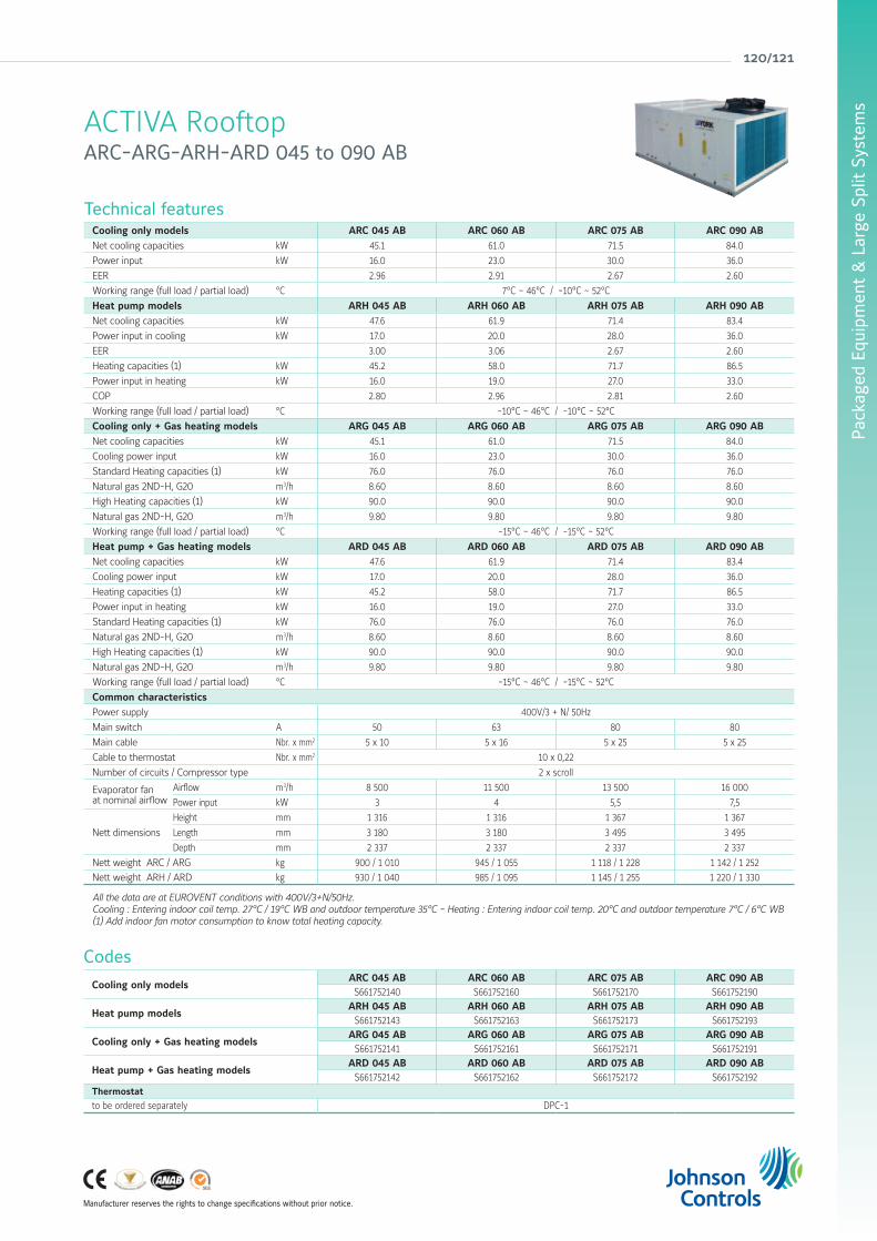
Pack
aged
Equ
ipm
ent
& L
arge
Spl
it S
yste
ms
Manufacturer reserves the rights to change specifications without prior notice.
120/121
ACTIVA RooftopARC-ARG-ARH-ARD 045 to 090 AB
Technical featuresCooling only models ARC 045 AB ARC 060 AB ARC 075 AB ARC 090 ABNet cooling capacities kW 45.1 61.0 71.5 84.0
Power input kW 16.0 23.0 30.0 36.0
EER 2.96 2.91 2.67 2.60
Working range (full load / partial load) °C 7°C ~ 46°C / -10°C ~ 52°C
Heat pump models ARH 045 AB ARH 060 AB ARH 075 AB ARH 090 ABNet cooling capacities kW 47.6 61.9 71.4 83.4
Power input in cooling kW 17.0 20.0 28.0 36.0
EER 3.00 3.06 2.67 2.60
Heating capacities (1) kW 45.2 58.0 71.7 86.5
Power input in heating kW 16.0 19.0 27.0 33.0
COP 2.80 2.96 2.81 2.60
Working range (full load / partial load) °C -10°C ~ 46°C / -10°C ~ 52°C
Cooling only + Gas heating models ARG 045 AB ARG 060 AB ARG 075 AB ARG 090 ABNet cooling capacities kW 45.1 61.0 71.5 84.0
Cooling power input kW 16.0 23.0 30.0 36.0
Standard Heating capacities (1) kW 76.0 76.0 76.0 76.0
Natural gas 2ND-H, G20 m3/h 8.60 8.60 8.60 8.60
High Heating capacities (1) kW 90.0 90.0 90.0 90.0
Natural gas 2ND-H, G20 m3/h 9.80 9.80 9.80 9.80
Working range (full load / partial load) °C -15°C ~ 46°C / -15°C ~ 52°C
Heat pump + Gas heating models ARD 045 AB ARD 060 AB ARD 075 AB ARD 090 ABNet cooling capacities kW 47.6 61.9 71.4 83.4
Cooling power input kW 17.0 20.0 28.0 36.0
Heating capacities (1) kW 45.2 58.0 71.7 86.5
Power input in heating kW 16.0 19.0 27.0 33.0
Standard Heating capacities (1) kW 76.0 76.0 76.0 76.0
Natural gas 2ND-H, G20 m3/h 8.60 8.60 8.60 8.60
High Heating capacities (1) kW 90.0 90.0 90.0 90.0
Natural gas 2ND-H, G20 m3/h 9.80 9.80 9.80 9.80
Working range (full load / partial load) °C -15°C ~ 46°C / -15°C ~ 52°C
Common characteristicsPower supply 400V/3 + N/ 50Hz
Main switch A 50 63 80 80
Main cable Nbr. x mm2 5 x 10 5 x 16 5 x 25 5 x 25
Cable to thermostat Nbr. x mm2 10 x 0,22
Number of circuits / Compressor type 2 x scroll
Evaporator fan at nominal airflow
Airflow m3/h 8 500 11 500 13 500 16 000
Power input kW 3 4 5,5 7,5
Nett dimensions
Height mm 1 316 1 316 1 367 1 367
Length mm 3 180 3 180 3 495 3 495
Depth mm 2 337 2 337 2 337 2 337
Nett weight ARC / ARG kg 900 / 1 010 945 / 1 055 1 118 / 1 228 1 142 / 1 252
Nett weight ARH / ARD kg 930 / 1 040 985 / 1 095 1 145 / 1 255 1 220 / 1 330
All the data are at EUROVENT conditions with 400V/3+N/50Hz.Cooling : Entering indoor coil temp. 27°C / 19°C WB and outdoor temperature 35°C - Heating : Entering indoor coil temp. 20°C and outdoor temperature 7°C / 6°C WB(1) Add indoor fan motor consumption to know total heating capacity.
Codes
Cooling only models ARC 045 AB ARC 060 AB ARC 075 AB ARC 090 AB
S661752140 S661752160 S661752170 S661752190
Heat pump modelsARH 045 AB ARH 060 AB ARH 075 AB ARH 090 AB
S661752143 S661752163 S661752173 S661752193
Cooling only + Gas heating modelsARG 045 AB ARG 060 AB ARG 075 AB ARG 090 AB
S661752141 S661752161 S661752171 S661752191
Heat pump + Gas heating modelsARD 045 AB ARD 060 AB ARD 075 AB ARD 090 AB
S661752142 S661752162 S661752172 S661752192Thermostat
to be ordered separately DPC-1

york air-conditioning products
Activa rooftop details & features
PCB boardThe new control board keeps same features and benefits as YKlon V3 (see pg. 159) and adds new logical to control the tandem circuit, the new options (heat recovery, return fan) and the possibility to communicate with BMS system as standard (N2Open).
Condenser fanNew condenser fans with high technology blades and outdoor bell that reduce the turbulences in the air and therefore increase the efficiency and improve the noise level performance.
PCB board
Return fanLocated in a special roof curb underneath the rooftop, it works simultaneously with the indoor fan in order to balance the amount of air supplied to and removed from the space. It is the best suited for systems with high return path static pressures.Also, incorporates EC technology and a differential pressure gauge to easy set up and maintain automatically the working point in the installation.
Tandem scroll compressorsTandem compressors configuration allows the unit to operate at partial load (only with one compressor) with higher efficiency and increases the working range up to +52°C ambient temperature.
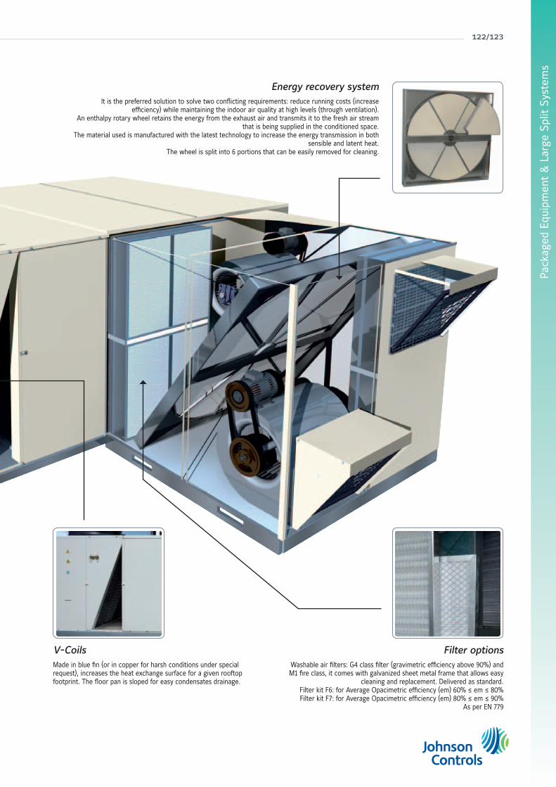
Pack
aged
Equ
ipm
ent
& L
arge
Spl
it S
yste
ms
122/123
V-CoilsMade in blue fin (or in copper for harsh conditions under special request), increases the heat exchange surface for a given rooftop footprint. The floor pan is sloped for easy condensates drainage.
Energy recovery systemIt is the preferred solution to solve two conflicting requirements: reduce running costs (increase
efficiency) while maintaining the indoor air quality at high levels (through ventilation).An enthalpy rotary wheel retains the energy from the exhaust air and transmits it to the fresh air stream
that is being supplied in the conditioned space.The material used is manufactured with the latest technology to increase the energy transmission in both
sensible and latent heat.The wheel is split into 6 portions that can be easily removed for cleaning.
Filter optionsWashable air filters: G4 class filter (gravimetric efficiency above 90%) and M1 fire class, it comes with galvanized sheet metal frame that allows easy
cleaning and replacement. Delivered as standard.Filter kit F6: for Average Opacimetric efficiency (em) 60% ≤ em ≤ 80%Filter kit F7: for Average Opacimetric efficiency (em) 80% ≤ em ≤ 90%
As per EN 779

york air-conditioning products
Accessories & options
CodeCooling only Heat pump
45 60 75 90 45 60 75 90
Thermostat DPC-1 S603786044 A A A A A A A A
Dry bulb triple input economizer or motorized air damper with rain hood
S661752301 O O O O
S661752311 O O O O
Enthalpy probes S613990081 O O O O O O O O
Indoor air quality sensor S606819964 A A A A A A A A
Power Exhaust S661752302 A A A A
S661752322 A A A A
Barometric relief damper and rain hoodS613990472 A A A A
S613990473 A A A A
Fresh air damper and rain hood (2)S661752303 A A A A
S661752323 A A A A
High speed drive
4 kW S611990401 O O
5.5 kW S611990601 O O
7.5 kW S611990701 O O
9.2 kW S611990901 O O
11 kW S611990902 O O
Soft start indoor fan5.5 kW S606744690 O O O O O O O O
11.5 kW S606744691 O O O O O O O O
Low ambient kit S613118301 O O O O O O O O
Side duct flangesS613991482 A A A A
S613991483 A A A A
Fixed roof curbS613991884 A A A A
S613991885 A A A A
Adjustable roof curb S613992081 A A A A
S613992082 A A A A
Dirty filter switch S613990085 O O O O O O O O
Smoke detector S613995382 O O O O O O O O
Fire detection thermostat S613903003 O O O O O O O O
Hot water coil S611083351 O O O O O O O O
Electric heaters
12 kW S611761584 O O O O O O O O
25 kW S611762284 O O O O O O O O
37 kW S611763385 O O O O O O O O
50 kW S611764485 O O O O O O O O
Propane conversion Kit S611801780 A A A A A A A A
High heat gas conversion kit S611803080 O O O O O O O O
Filter kit F6
S611300401 O O O O
S611300701 O O
S611300901 O O
Filter kit F7
S611300402 O O O O
S611300702 O O
S611300902 O O
Grill condenser coil protection
S661752304 O O
S661752324 O O
S661752314 O O O O
Antivibration mounting kit S613990411 A A A A A A A A
Return fan bottom ductS613993042 A A A A
S613993072 A A A A
Energy recovery
Q6000 (1) S611994501 A A A A
Q3000 (1) S611994502 A A A A
Q9000 (1) S611997501 A A A A
Q4500 (1) S611997502 A A A A
Filter kit F6 for energy recoveryS611994506 O/A O/A O/A O/A
S611997506 O/A O/A O/A O/A
Filter kit F7 for energy recoveryS611994507 O/A O/A O/A O/A
S611997507 O/A O/A O/A O/A
Alarm relay board S606791243 O/A O/A O/A O/A O/A O/A O/A O/A
Copper-copper coil Contact us O O O O O O O O
O=Option (factory fitted). A=Accessory (supplied loose). O/A=If you want this item factory fitted, precise it in the order form. (1) = Energy recovery accessory include: economizer, rain hood, indoor air quality sensor, enthalpy probe and G4 filters.(2) Fresh air damper can not be installed if economizer or motorized damper is fitted
Accessories & options

Pack
aged
Equ
ipm
ent
& L
arge
Spl
it S
yste
ms
124/125
Accessories & options
CodeCooling + gas heating Heat pump + gas heating
45 60 75 90 45 60 75 90
Thermostat DPC-1 S603786044 A A A A A A A A
Dry bulb triple input economizer or motorized air damper with rain hood
S661752301 O O O O
S661752311 O O O O
Enthalpy probes S613990081 O O O O O O O O
Indoor air quality sensor S606819964 A A A A A A A A
Power Exhaust S661752302 A A A A
S661752322 A A A A
Barometric relief damper and rain hoodS613990472 A A A A
S613990473 A A A A
Fresh air damper and rain hood (2)S661752303 A A A A
S661752323 A A A A
High speed drive
4 kW S611990401 O O
5.5 kW S611990601 O O
7.5 kW S611990701 O O
9.2 kW S611990901 O O
11 kW S611990902 O O
Soft start indoor fan5.5 kW S606744690 O O O O O O O O
11.5 kW S606744691 O O O O O O O O
Low ambient kit S613118301 O O O O O O O O
Side duct flangesS613991482 A A A A
S613991483 A A A A
Fixed roof curbS613991884 A A A A
S613991885 A A A A
Adjustable roof curb S613992081 A A A A
S613992082 A A A A
Dirty filter switch S613990085 O O O O O O O O
Smoke detector S613995382 O O O O O O O O
Fire detection thermostat S613903003 O O O O O O O O
Hot water coil S611083351
Electric heaters
12 kW S611761584
25 kW S611762284
37 kW S611763385
50 kW S611764485
Propane conversion Kit S611801780 A A A A A A A A
High heat gas conversion kit S611803080 O O O O O O O O
Filter kit F6
S611300401 O O O O
S611300701 O O
S611300901 O O
Filter kit F7
S611300402 O O O O
S611300702 O O
S611300902 O O
Grill condenser coil protection
S661752304 O O
S661752324 O O
S661752314 O O O O
Antivibration mounting kit S613990411 A A A A A A A A
Return fan bottom ductS613993042 A A A A
S613993072 A A A A
Energy recovery
Q6000 (1) S611994501 A A A A
Q3000 (1) S611994502 A A A A
Q9000 (1) S611997501 A A A A
Q4500 (1) S611997502 A A A A
Filter kit F6 for energy recoveryS611994506 O/A O/A O/A O/A
S611997506 O/A O/A O/A O/A
Filter kit F7 for energy recoveryS611994507 O/A O/A O/A O/A
S611997507 O/A O/A O/A O/A
Alarm relay board S606791243 O/A O/A O/A O/A O/A O/A O/A O/A
Copper-copper coil Contact us O O O O O O O O
O=Option (factory fitted). A=Accessory (supplied loose). O/A=If you want this item factory fitted, precise it in the order form. (1) = Energy recovery accessory include: economizer, rain hood, indoor air quality sensor, enthalpy probe and G4 filters.(2) Fresh air damper can not be installed if economizer or motorized damper is fitted
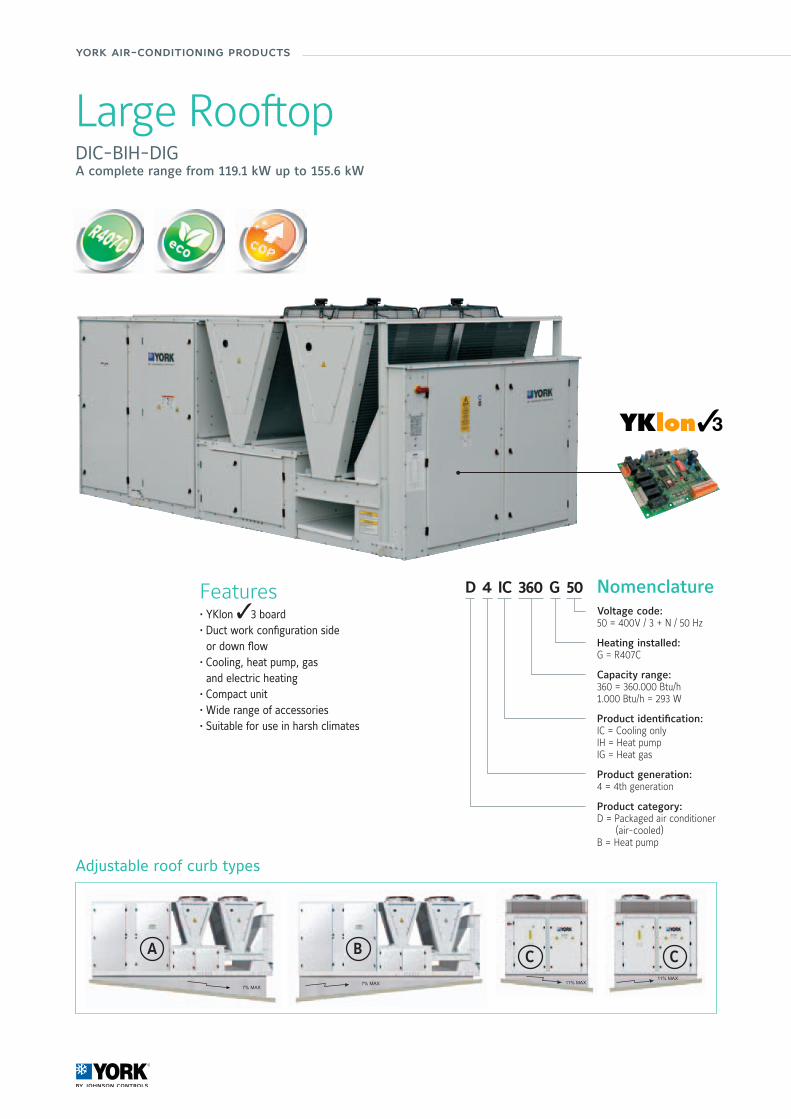
york air-conditioning products
D 4 IC 360 G 50 NomenclatureVoltage code:50 = 400V / 3 + N / 50 Hz
Heating installed:G = R407C
Capacity range:360 = 360.000 Btu/h1.000 Btu/h = 293 W
Product identification:IC = Cooling onlyIH = Heat pumpIG = Heat gas
Product generation:4 = 4th generation
Product category:D = Packaged air conditioner (air-cooled)B = Heat pump
A C CB
Adjustable roof curb types
Large RooftopDIC-BIH-DIGA complete range from 119.1 kW up to 155.6 kW
Features• YKlon 33 board• Duct work configuration side or down flow• Cooling, heat pump, gas and electric heating• Compact unit• Wide range of accessories• Suitable for use in harsh climates

Pack
aged
Equ
ipm
ent
& L
arge
Spl
it S
yste
ms
Manufacturer reserves the rights to change specifications without prior notice.
126/127
Technical featuresModels D4IC 360 G D4IC 480 G B4IH 360 G B4IH 480 G D4IG 360 G* D4IG 480 G*Gross cooling capacities (1) kW 119.1 155.6 115.1 151.0 119.1 155.6Power input in cooling (2) kW 31.4 37.2 32.0 44.5 31.4 37.2Heating capacities kW - - 127.1 163.3 - -Power input in heating kW - - 41.9 56.7 - -Cooling capacities (3) kW 111.6 144.6 107.6 140.0 111.6 144.6Power input in cooling (3) kW 42.4 52.2 43.0 59.5 42.4 52.2Heating capacities (3) kW - - 127.1 163.3 - -Power input in heating (3) kW - - 41.9 56.7 - -Gas heating capacities (3) kW 117 + 9.2 117 + 11Natural gas 2ND-H, G20 m3/h 12.8 12.8Power supply 400V/3 + N/ 50HzNominal / Starting current A 89 / 167 109 / 250 83 / 169 109 / 250 89 / 167 109 / 250Main switch A 125 160 125 160 125 160Main cable Nbr x mm2 5 x 50 5 x 70 5 x 50 5 x 70 5 x 50 5 x 70Cable to thermostat DPC-1 Nbr x mm2 10 x 0,22 shield cable onlyNumber of circuits 3 3 3 3 3 3Thermostat DPC-1
Evaporator fanat nominal airflow
Airflow m3/h 21 000 25 000 21 000 25 000 21 000 25 000Standard ESP Pa 250 250 250 250 250 250ESP with HSD Pa 400 (Side duct connections) - 450 (Down duct connections)Power input kW 9.2 11 9.2 11 9.2 11Power input HSD kW 11 15 11 15 11 15Drive Pulley - Belt (6 turns adjustable)
Nett dimensionsHeight mm 1.815Length mm 4.580Depth mm 2.200
Nett weight kg 2 010 2 295 2 060 2 350 2 125 2 410
(1) : without heat from evaporator fan motor (2) : without evaporator fan motor (3) : All the data are at EUROVENT conditions with 230V/1/50Hz or 400V/3+N/50HzCooling : Entering indoor coil temp. 27°C / 19°C WB and outdoor temperature 35°C - Heating : Entering indoor coil temp. 20°C and outdoor temperature 7°C / 6°C WB* You should indicate airflow connection (side or down) when placing order.
Compatibility table / Codes
Cooling only models D4IC 360 G D4IC 480 GS661723680 S661724880
Heat pump modelsB4IH 360 G B4IH 480 GS661923680 S661924880
Cooling and gas heating modelsD4IG 360 G D4IG 480 GS661763681 S661764882
Thermostat
to be ordered separately DPC-1
Accessories or optionsModels D4IC 360 G D4IC 480 G B4IH 360 G B4IH 480 G D4IG 360 G D4IG 480 GThermostat DPC-1 S603780044 A A A A A ADry bulb triple input economizer ormotorized air damper with rain hood (1) S613993601 O O O O O O
Enthalpy probe * S613990081 O O O O O OIndoor air quality sensor * S606819964 O/A O/A O/A O/A O/A O/APower exhaust * S613994880 O/A O/A O/A O/A O/A O/ABarometric relief damper + rain hood S613990471 O/A O/A O/A O/A O/A O/AFresh air damper and rain hood (2) S613990488 O O O O O OHigh pressure drive 360 S611993680 O O OHigh pressure drive 480 S611994880 O O OLow ambient control 360 and 480 S613113680 O O O O O OHot water coil with control S611083651 O O O OElectric heater 37 kW (2 stages) S611763384 O O O OElectric heater 50 kW (2 stages) S611764484 O O O OElectric heater 60 kW (2 stages) S611765581 O O O OWashable air filter set G4 (EU4) S611303680 O O O O O ODirty filter switch S613990084 O O O O O OSmoke detector S613995381 O O O O O OFire detection thermostat S613903002 O O O O O OFixed roof curb ** S613991980 A A A A A A
Adjustable roof curb **A S613992084 A A A A A AB S613992085 A A A A A AC S613992086 A A A A A A
O=Option (factory fitted). A=Accessory (supplied loose). O/A=If you want this item factory fitted, precise it in the order form. * It is mandatory to order the economizer with this item. ** Delivered in kit form. (1) You should indicate airflow connection (side or down) when placing order. (2) Fresh air damper can not be installed if economizer or motorized damper is fitted
Large RooftopDIC-BIH-DIG 360 to 480 G

york air-conditioning products
Fire detection thermostatThis fire detection thermostat is protecting the AHU but must not be used to ensure a full building protection against fire danger. The standard AHU is protected as standard with a Supply Air probe that shuts the unit down (lockout) when temperature exceeds 80°C. The electro-mechanical fire detection thermostat is used to fulfil specific local requirement. A manual reset is necessary.
Motorised outdoor air damperEquipped with the same dampers as the economizer, the Return Air probe is not used. Outdoor air damper opens to pre-set position whenever the indoor fan is operating (selected from the thermostat, the indoor fan can be activated with the compressor or to operate continuously) and will drive fully closed when the indoor fan shuts down. The rain hood is painted to match the basic unit and aluminium mesh pre-filter prevents water penetration.
Enthalpy sensorsTo control the economizer in humid areas, or when indoor air humidity needs to remains dry, you should select enthalpy regulation. Enthalpy sensors will be used with the triple input economizer.
Fresh air damper and rain hoodThe most cost effective method with a complete rain hood and a fixed damper that can be adjusted to provide approximately 10, 15 or 25% of fresh air.
Barometric relief damperThis accessory can be used to relieve internal air pressure on units equipped with triple input economiser or motorised air damper but no power exhaust. When the rooftop is working in free cooling or introducing fresh air, the damper opens to relieve over pressure from the return air section. This accessory is comprised of a rain hood, a protective grille and a fully assembled damper.
Triple input economizerThis system utilizes 3 probes: Return Air, Outdoor Air and Supply Air. The Outdoor Air damper and the Return Air dampers are mechanically interconnected in order to provide the same airflow at the coil inlet, with a single damper motor. The PCB compares sensor values and modulates the dampers providing maximum efficiency of the economiser system (free cooling) and comfort (Supply Air > 12°C). Combined with the air quality sensor, your payback will be ensured within few months. The rain hood is painted to match the basic unit and aluminium mesh pre-filter prevents water penetration.
Power ExhaustUsed to mechanically relieve internal air pressure from the Return Air section and ensure efficient fresh air introduction on units equipped with triple input economiser or motorised air damper. The power exhaust fan motor works when enough Outdoor Air is blowing into the room and if Outdoor Air temperature is acceptable (12°C < t° < 30°C).
High speed driveThe high speed drive will increase the supply fan performance for applications requiring greater air flow and/or static pressure.Please consult technical guide for more information.
Low ambient controlAll our rooftops are designed to work in cooling mode down to 7°C ambient temperatures. Although this working range suits most applications, the units can operate correctly down to -18°C with optional low ambient control.
Dirty filter switchEnsures that clean air is being supplied, advises when maintenance is required to prevent excessive depression and ensures water integrity of the AHU. These are the main advantages of filter dirty switch. Connected with the DPC-1 thermostat, the filter icon will appear on the thermostat screen when a filter change is required.
Indoor air qualityThis sensor measures concentrations of pollutant gases, such as tobacco smoke, human body odours, kitchen odours, carbon monoxide, etc… It automatically overrides the economizer when pollutant levels rise above preset limits. A shorting plug will set the algorithm to acceptable, good or very good air quality. This VOC sensor (Volatile Organic Compounds) sends an ON/OFF signal to the control PCB. The YKlon will then adjust the fresh air damper, optimising indoor air quality and minimising the energy consumption.
Smoke detectorThe smoke detector is protecting the AHU but must not be used to ensure a full building protection against smoke danger. If smoke is detected the AHU is shutdown (lockout). A manual reset is necessary.
Rooftop & Large Rooftop accessories & options

Pack
aged
Equ
ipm
ent
& L
arge
Spl
it S
yste
ms
128/129
Side duct flangesFitted as standard on units 90, 120 and 150, this accessory is composed of easy to install sheet metal panels to allow ductwork connections on the side of the AHU for horizontal return air and/or supply air.
Kit conversion propaneThis kit comprises replacement burner, pilot injectors and all necessary instructions for converting the natural gas burner to propane gas. The nominal pressure of the propane gas should be 37 mbar.
High heat gasThis kit comprises replacement burner injectors and all necessary instructions to provide high heat capacity for gas rooftop.
Hot water coil with controlThe hot water coil and his control are always fitted, wired and factory tested. Located in the supply air section, side or bottom duct connection is possible without any modification. Complete with an anti-frost thermostat, the PCB will activate the modulated valve (24V supply, 0 – 10V modulating signal) in order to get the best comfort. A jumper will allow using hot water coil as 1st heating stage.
Electric heatersAvailable on cooling only and Heat pump units, the electric heater is protected with two overheats per element.When the overheat operates, there is a lock out of the faulty electric heater stage and the PCB starts automatically another heat stage.
Air filtersG4, F6 and F7 filters are available to purify the air in the room. M1 fire class and manufactured in sheet metal frame, they are easy to install and clean.
Indoor fan soft startCompact control unit with a motor with AC semiconductors, designed for soft starting and stopping of three-phase motors for centrifugal fans. The starting time, the stopping time and the initial torque are adjusted by mean of independent potentiometers.
Return fanUsed to overcome high return path pressure drops, works in series with the indoor fan to maintain the air pressure of the conditioned space within acceptable levels.
Grill condenser protectionMetallic frame painted with oven-baked polymerized paint (800h salt spray resistance) to protect the fins of the coils from external damages.
Fixed and adjustable roof curbsIdeal for down-flow applications, it is a great help for installation allowing duct connections, electrical connection and weatherproofing between the roofcurb and the roof of the building. Shipped in kit form, it also gives sufficient height for condensate trap operation.
The adjustable roof curbs have the same benefits as the fixed roof curb, it allows the rooftop to be levelled on a roof with up to 7° slope (4%).
Antivibration mounting kitIt is composed by a set of stainless steel springs, to be assembled underneath the rooftop in a specific position. Their installation avoids the potential vibration transmission of the equipment to the building and reduces therefore the noise level (compressors have their own shock absorbers delivered as standard).
Energy recoveryAttached to the return air box of the rooftop, a rotary enthalpy wheel retrieves the energy of the exhausted air and transmits it to the fresh air intake. A special material used in the wheel allows that latent heat as well as sensible heat are transmitted.

york air-conditioning products
VITALITY Axial Fan Large SplitVAC/VAH - VIR 20 to 90 ABA complete range from 19.1 kW up to 86.1 kW
Features• New YKN2open board • High technology fan blades increases efficiency and reduces noise level
• Service valves• Economizer or motorized damper• Return fan• Indoor air quality• Hot water coil and control• Scroll compressor with crankcase heater• Digital thermostat DPC-1 included
B = Blue finC = Copper fin (ask JCI)
A = version
Capacity range:40 = 40 kW
Product category:C = Cooling onlyH = Heat PumpR = ReversibleI = Indoor
A = Axial
V = Vitality
V A H 40 A B Nomenclature
YKN2open
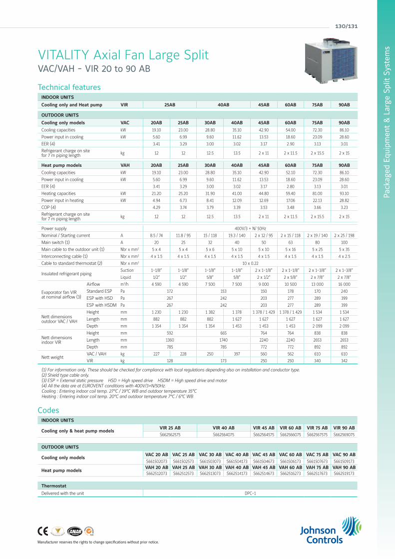
Pack
aged
Equ
ipm
ent
& L
arge
Spl
it S
yste
ms
Manufacturer reserves the rights to change specifications without prior notice.
130/131
Technical featuresINDOOR UNITS
Cooling only and Heat pump VIR 25AB 40AB 45AB 60AB 75AB 90AB
OUTDOOR UNITS
Cooling only models VAC 20AB 25AB 30AB 40AB 45AB 60AB 75AB 90AB
Cooling capacities kW 19.10 23.00 28.80 35.10 42.90 54.00 72.30 86.10
Power input in cooling kW 5.60 6.99 9.60 11.62 13.53 18.60 23.09 28.60
EER (4) 3.41 3.29 3.00 3.02 3.17 2.90 3.13 3.01
Refrigerant charge on sitefor 7 m piping length kg 12 12 12.5 13.5 2 x 11 2 x 11.5 2 x 15.5 2 x 15
Heat pump models VAH 20AB 25AB 30AB 40AB 45AB 60AB 75AB 90AB
Cooling capacities kW 19.10 23.00 28.80 35.10 42.90 52.10 72.30 86.10
Power input in cooling kW 5.60 6.99 9.60 11.62 13.53 18.60 23.09 28.60
EER (4) 3.41 3.29 3.00 3.02 3.17 2.80 3.13 3.01
Heating capacities kW 21.20 25.20 31.90 41.00 44.80 59.40 81.00 93.10
Power input in heating kW 4.94 6.73 8.41 12.09 12.69 17.06 22.13 28.82
COP (4) 4.29 3.74 3.79 3.39 3.53 3.48 3.66 3.23
Refrigerant charge on sitefor 7 m piping length kg 12 12 12.5 13.5 2 x 11 2 x 11.5 2 x 15.5 2 x 15
Power supply 400V/3 + N/ 50Hz
Nominal / Starting current A 8.5 / 74 11.8 / 95 15 / 118 19.3 / 140 2 x 12 / 95 2 x 15 / 118 2 x 19 / 140 2 x 25 / 198
Main switch (1) A 20 25 32 40 50 63 80 100
Main cable to the outdoor unit (1) Nbr x mm2 5 x 4 5 x 4 5 x 6 5 x 10 5 x 10 5 x 16 5 x 25 5 x 35
Interconnecting cable (1) Nbr x mm2 4 x 1.5 4 x 1.5 4 x 1.5 4 x 1.5 4 x 1.5 4 x 1.5 4 x 1.5 4 x 2.5
Cable to standard thermostat (2) Nbr x mm2 10 x 0.22
Insulated refrigerant pipingSuction 1-1/8” 1-1/8” 1-1/8” 1-1/8” 2 x 1-1/8” 2 x 1-1/8” 2 x 1-3/8” 2 x 1-3/8”
Liquid 1/2” 1/2” 5/8” 5/8” 2 x 1/2” 2 x 5/8” 2 x 7/8” 2 x 7/8”
Evaporator fan VIR at nominal airflow (3)
Airflow m3/h 4 590 4 590 7 500 7 500 9 000 10 500 13 000 16 000
Standard ESP Pa 172 153 150 178 170 240
ESP with HSD Pa 267 242 203 277 289 399
ESP with HSDM Pa 267 242 203 277 289 399
Nett dimensionsoutdoor VAC / VAH
Height mm 1 230 1 230 1 382 1 378 1 378 / 1 429 1 378 / 1 429 1 534 1 534
Length mm 882 882 882 1 627 1 627 1 627 1 627 1 627
Depth mm 1 354 1 354 1 354 1 453 1 453 1 453 2 099 2 099
Nett dimensionsindoor VIR
Height mm 592 665 764 764 838 838
Length mm 1360 1740 2240 2240 2653 2653
Depth mm 785 785 772 772 892 892
Nett weightVAC / VAH kg 227 228 250 397 560 562 610 610
VIR kg 128 173 250 250 340 342
(1) For information only. These should be checked for compliance with local regulations depending also on installation and conductor type.(2) Shield type cable only. (3) ESP = External static pressure HSD = High speed drive HSDM = High speed drive and motor(4) All the data are at EUROVENT conditions with 400V/3+N/50Hz.Cooling : Entering indoor coil temp. 27°C / 19°C WB and outdoor temperature 35°CHeating : Entering indoor coil temp. 20°C and outdoor temperature 7°C / 6°C WB
VITALITY Axial Fan Large SplitVAC/VAH - VIR 20 to 90 AB
CodesINDOOR UNITS
Cooling only & heat pump modelsVIR 25 AB VIR 40 AB VIR 45 AB VIR 60 AB VIR 75 AB VIR 90 ABS662562575 S662564075 S662564575 S662566075 S662567575 S662569075
OUTDOOR UNITS
Cooling only modelsVAC 20 AB VAC 25 AB VAC 30 AB VAC 40 AB VAC 45 AB VAC 60 AB VAC 75 AB VAC 90 ABS661502073 S661502573 S661503073 S661504173 S661504673 S661506173 S661507673 S661509173
Heat pump modelsVAH 20 AB VAH 25 AB VAH 30 AB VAH 40 AB VAH 45 AB VAH 60 AB VAH 75 AB VAH 90 ABS662512073 S662512573 S662513073 S662514173 S662514673 S662516273 S662517673 S662519173
Thermostat
Delivered with the unit DPC-1

york air-conditioning products
Compatibility table / CodesINDOOR UNITS
Cooling only & heat pumpVIR 25 AB VIR 40 AB VIR 45 AB VIR 60 AB VIR 75 AB VIR 90 AB
S662562575 S662564075 S662564575 S662566075 S662567575 S662569075
OUTDOOR UNITS
Cooling only modelsVAC 20 AB VAC 25 AB VAC 30 AB VAC 40 AB VAC 45 AB VAC 60 AB VAC 75 AB VAC 90 AB
S661502073 S661502573 S661503073 S661504173 S661504673 S661506173 S661507673 S661509173
Heat pump modelsVAH 20 AB VAH 25 AB VAH 30 AB VAH 40 AB VAH 45 AB VAH 60 AB VAH 75 AB VAH 90 AB
S662512073 S662512573 S662513073 S662514173 S662514673 S662516273 S662517673 S662519173
Thermostat
Delivered with the unit DPC-1
Accessories or options for outdoor units
20AB 25AB 30AB 40AB 45AB 60AB 75AB 90AB
Low Ambient KitS606819974 O O O OS606819975 O O O O
Soft start compressorS606744692 O O O OS606744693 O O O O
Alarm relay board S606791243 O/A O/A O/A O/A O/A O/A O/A O/ACopper-copper coil Contact us O O O O O O O O
Accessories or options for indoor units
VIR models 25A 40AB 45AB 60AB 75AB 90AB
Electrical Heaters(Inside the unit)(cable 20 m included)
10 kW (1 stage) S611763704 O/A
15 kW (1 stage) S611763714 O/A
10 kW (1 stage) S611763724 O/A
20 kW (2 stages) S611763734 O/A
15 kW (1 stage) S611763744 O/A O/A
30 kW (2 stages) S611763754 O/A O/A
30 kW (2 stages) S611763764 O/A O/A
40 kW (2 stages) S611763774 O/A O/A
50 m connecting cable1 stage S611763780 A A A A
2 stages S611763781 A A A A A
Economizer or Motorised damper(dry bulb sensors included)(cable 20 m included)
S613994250 A
S613994400 A
S613994450 A A
S613994750 A A
Indoor air quality S606819964 A A A A A A
Hot water coil and control(cable 20 m included)
S611082513 O
S611084010 O
S611084512 O O
S611087510 O O
50 m communication cable (Economizer/HWC) S611087520 * A A A A A A
Return fanS613995450 A A
S613995750 A A
Vertical discharge Kit
S669482502 O
S669484002 O
S669486002 O O
S669487502 O O
Indoor fan smooth start up to 5,5 kW S606744690 O O O O O O
High speed drive
S611991087 O
S611991089 O
S611991091 O O
S611991092 O
S611991095 O
High speed drive and motor
S611991088 O
S611991090 O
S611991093 O
S611991094 OS611991096 O
O = Option (factory fitted) A = Accessory (supplied loose) O/A = If you want this item factory fitted, precise it in the order form (1) Factory fitted, for horizontal airflow only.* If the unit is equipped with economizer and hot water coil, only 1 communication cable is necessary.
Accessories or options

Pack
aged
Equ
ipm
ent
& L
arge
Spl
it S
yste
ms
132/133
Indoor units dimensions
All dimensions in mm. Drawings not a scale.
VIR 25 AB
L
BCD FE
IJ
K
A
M N
Electrical connections
Piping connections
Unit A B C D E F G H I J K L M N
VIR 25 AB 592 1360 785 480 403 480 - - 347 40 1094 520 21 25
VIR 40-45-60 AB
L
BCF G
IJ
ED H
K
A
M N
Electrical connections
Piping connections
Unit A B C D E F G H I J K L M N
VIR 40 AB 665 1740 785 442 316 229 316 442 347 79 1337 593 21 25VIR 45 AB 764 2240 772 567 401 309 401 567 347 79 1920 692 21 25VIR 60 AB 764 2240 772 567 401 309 401 567 347 79 1920 692 21 25
All dimensions in mm. Drawings not a scale.
VIR 75-90 AB
Unit A B C D E F G H I J K L M N
VIR 75 AB 838 2653 892 663 478 376 478 663 409 79 2196 766 21 25VIR 90 AB 838 2653 892 663 478 376 478 663 409 79 2196 766 21 25
All dimensions in mm. Drawings not a scale.
Electrical connections L
BCF HG
JI
ED
A
KM N
Piping connections
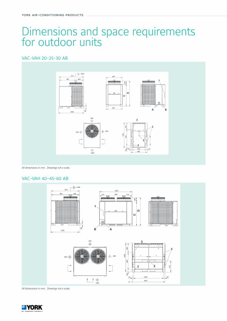
york air-conditioning products
VAC-VAH 20-25-30 AB
All dimensions in mm. Drawings not a scale.
VAC-VAH 40-45-60 AB
All dimensions in mm. Drawings not a scale.
Dimensions and space requirementsfor outdoor units
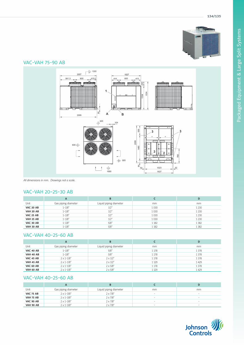
Pack
aged
Equ
ipm
ent
& L
arge
Spl
it S
yste
ms
134/135
VAC-VAH 75-90 AB
VAC-VAH 20-25-30 AB
VAC-VAH 40-25-60 AB
VAC-VAH 40-25-60 AB
All dimensions in mm. Drawings not a scale.
A B C D
Unit Gas piping diameter Liquid piping diameter mm mm
VAC 20 AB 1-1/8” 1/2” 1 030 1 230VAH 20 AB 1-1/8” 1/2” 1 030 1 230VAC 25 AB 1-1/8” 1/2” 1 030 1 230VAH 25 AB 1-1/8” 1/2” 1 030 1 230VAC 30 AB 1-1/8” 5/8” 1 182 1 382VAH 30 AB 1-1/8” 5/8” 1 182 1 382
A B C D
Unit Gas piping diameter Liquid piping diameter mm mm
VAC 40 AB 1-1/8” 5/8” 1 178 1 378VAH 40 AB 1-1/8” 5/8” 1 178 1 378VAC 45 AB 2 x 1-1/8” 2 x 1/2” 1 178 1 378VAH 45 AB 2 x 1-1/8” 2 x 1/2” 1 129 1 429VAC 60 AB 2 x 1-1/8” 2 x 5/8” 1 178 1 378VAH 60 AB 2 x 1-1/8” 2 x 5/8” 1 129 1 429
A B C D
Unit Gas piping diameter Liquid piping diameter mm mm
VAC 75 AB 2 x 1-3/8” 2 x 7/8” - -VAH 75 AB 2 x 1-3/8” 2 x 7/8” - -VAC 90 AB 2 x 1-3/8” 2 x 7/8” - -VAH 90 AB 2 x 1-3/8” 2 x 7/8” - -
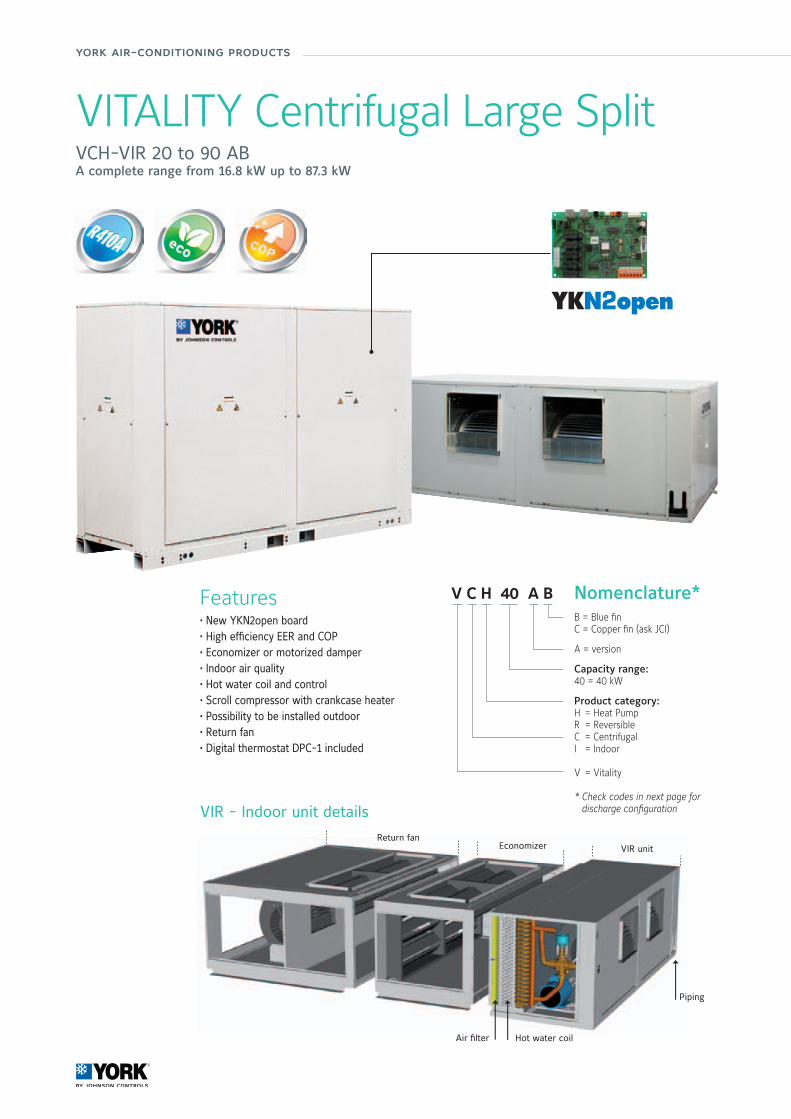
york air-conditioning products
B = Blue finC = Copper fin (ask JCI)
A = version
Capacity range:40 = 40 kW
Product category:H = Heat PumpR = ReversibleC = CentrifugalI = Indoor
V = Vitality
* Check codes in next page for discharge configuration
V C H 40 A B Nomenclature*
Air filter
Return fanEconomizer VIR unit
Hot water coil
Piping
VIR - Indoor unit details
VITALITY Centrifugal Large SplitVCH-VIR 20 to 90 ABA complete range from 16.8 kW up to 87.3 kW
Features• New YKN2open board • High efficiency EER and COP• Economizer or motorized damper• Indoor air quality• Hot water coil and control• Scroll compressor with crankcase heater• Possibility to be installed outdoor• Return fan• Digital thermostat DPC-1 included
YKN2open

Pack
aged
Equ
ipm
ent
& L
arge
Spl
it S
yste
ms
Manufacturer reserves the rights to change specifications without prior notice.
136/137
Technical featuresVITALITY UNITS
Heat pump models VCH/VIR 20 AB 25 AB 30 AB 40 AB 45 AB 60 AB 75 AB 90 AB
Cooling capacities kW 16.8 20.6 28.7 32.4 43.5 54.1 76.1 87.3
Power input in cooling kW 5.9 7.48 10.25 12.81 14.81 20.86 29.21 34.92
EER 2.85 2.75 2.8 2.53 2.94 2.6 2.61 2.5
Heating capacities kW 21.5 23.2 32.3 39.3 47.4 53 77.7 89.9
Power input in heating kW 5.68 6.84 9.95 12.87 13.75 20 27.56 33.19
COP 3.79 3.39 3.25 3.05 3.45 2.8 2.82 2.71
Refrigerant charge on sitefor 7m piping length kg 8.5 8.5 12 12 2 x 9.5 2 x 10.5 2 x 15 2 x 16
Power supply 400V/3 + N/ 50Hz
Nominal / Starting current A 13 / 16 / 22 / 27 / 33 / 43 / 59 / 72 /
Main switch (1) A 20 25 32 40 50 63 80 100
Main cable to the condensing unit (1) Nbr x mm2 5 x 4 5 x 4 5 x 6 5 x 10 5 x 10 5 x 16 5 x 25 5 x 35
Interconnecting cable (1) Nbr x mm2 4 x 1.5 4 x 1.5 4 x 1.5 4 x 1.5 4 x 1.5 4 x 1.5 4 x 1.5 4 x 2.5
Cable to standard thermostat (1) (2) Nbr x mm2 10 x 0.22
Insulated refrigerant pipingSuction 1 1/8" 1 1/8" 1 1/8" 1 1/8" 2 x 1 1/8" 2 x 1 1/8" 2 x 1 3/8" 2 x 1 3/8"
Liquid 1/2" 1/2" 5/8" 5/8" 2 x 1/2" 2 x 5/8" 2 x 7/8" 2 x 7/8"
Evaporator fan VIRat nominal airflow (3)
Airflow m3/h 4 590 7 500 9000 10500 13700 16000
Standard ESP Pa 117 118 130 137 125 175
ESP with HSD Pa - 217 188 246 260 -
ESP with HSDM Pa 222 - 188 246 260 354
Condenser fanat nominal airflow
Airflow m3/h 6235 6235 11975 11975 17250 20340 25200 25200
Standard ESP Pa 50 50 50 50 50 50 50 50
Nett dimensions VCHcondensing units
Height mm 1392 1392 1526 1526 1641 1641 1794 1794
Length mm 1362 1362 1740 1740 2240 2240 2658 2658
Depth mm 790 790 785 785 778 778 897 897
Nett dimensions VIRindoor units
Height mm 592 665 764 764 838 838
Length mm 1360 1740 2240 2240 2653 2653
Depth mm 785 785 772 772 892 892
Nett weightVCH kg 285 310 355 375 578 589 710 715
VIR kg 128 173 223 223 310 312
(1) For information only. These should be checked for compliance with local regulations depending also on installation and conductor type. (2) Shield type cable will have a better insulation against electromagnetic interference. It is recommended for sensitive sites and for communications. (3) ESP = External static pressure HSD = High speed drive HSDM = High speed drive and motorAll the data are at EUROVENT conditions with 400V/3+N/50Hz.Cooling : Entering indoor coil temp. 27°C / 19°C WB and outdoor temperature 35°CHeating : Entering indoor coil temp. 20°C and outdoor temperature 7°C / 6°C WB
CodesINDOOR UNITS
Cooling only & heat pump modelsVIR 25 AB VIR 40 AB VIR 45 AB VIR 60 AB VIR 75 AB VIR 90 ABS662562575 S662564075 S662564575 S662566075 S662567575 S662569075
OUTDOOR UNITS
Heat pump models VCH 20 AB VCH 25 AB VCH 30 AB VCH 40 AB VCH 45 AB VCH 60 AB VCH 75 AB VCH 90 ABwith horizontal discharge S662512043 S662512653 S662513043 S662514044 S662514543 S662516153 S662517543 S662519043with vertical discharge - - - - S662514565 S662516174 S662517564 S662519064
Thermostat
Delivered with the unit DPC-1
VITALITY Centrifugal Large SplitVCH-VIR 20 to 90 AB
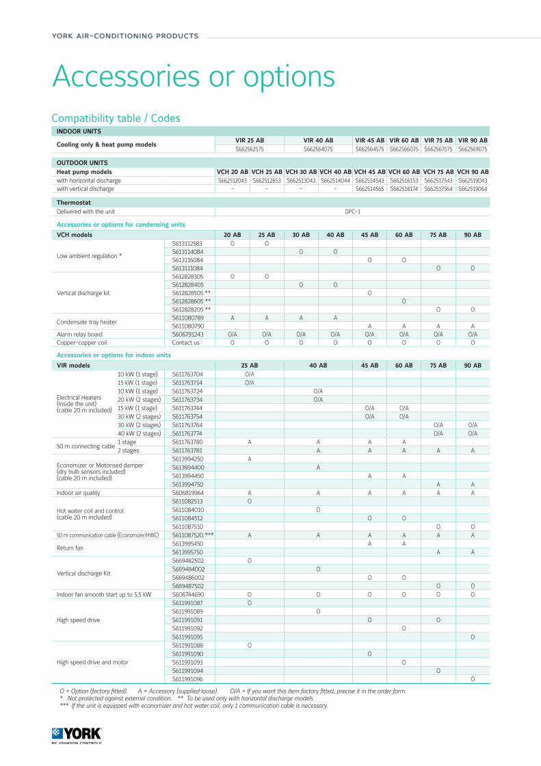
york air-conditioning products
Compatibility table / CodesINDOOR UNITS
Cooling only & heat pump modelsVIR 25 AB VIR 40 AB VIR 45 AB VIR 60 AB VIR 75 AB VIR 90 ABS662562575 S662564075 S662564575 S662566075 S662567575 S662569075
OUTDOOR UNITS Heat pump models VCH 20 AB VCH 25 AB VCH 30 AB VCH 40 AB VCH 45 AB VCH 60 AB VCH 75 AB VCH 90 ABwith horizontal discharge S662512043 S662512653 S662513043 S662514044 S662514543 S662516153 S662517543 S662519043with vertical discharge - - - - S662514565 S662516174 S662517564 S662519064
ThermostatDelivered with the unit DPC-1
Accessories or options for condensing units
VCH models 20 AB 25 AB 30 AB 40 AB 45 AB 60 AB 75 AB 90 AB
Low ambient regulation *
S613112583 O OS613114084 O OS613116084 O OS613111084 O O
Vertical discharge kit
S612828305 O OS612828405 O OS612828505 ** OS612828605 ** OS612828205 ** O O
Condensate tray heaterS611080789 A A A AS611080790 A A A A
Alarm relay board S606791243 O/A O/A O/A O/A O/A O/A O/A O/ACopper-copper coil Contact us O O O O O O O O
Accessories or options for indoor units
VIR models 25 AB 40 AB 45 AB 60 AB 75 AB 90 AB
Electrical Heaters(Inside the unit)(cable 20 m included)
10 kW (1 stage) S611763704 O/A15 kW (1 stage) S611763714 O/A10 kW (1 stage) S611763724 O/A20 kW (2 stages) S611763734 O/A15 kW (1 stage) S611763744 O/A O/A30 kW (2 stages) S611763754 O/A O/A30 kW (2 stages) S611763764 O/A O/A40 kW (2 stages) S611763774 O/A O/A
50 m connecting cable1 stage S611763780 A A A A2 stages S611763781 A A A A A
Economizer or Motorised damper(dry bulb sensors included)(cable 20 m included)
S613994250 AS613994400 AS613994450 A AS613994750 A A
Indoor air quality S606819964 A A A A A A
Hot water coil and control(cable 20 m included)
S611082513 OS611084010 OS611084512 O OS611087510 O O
50 m communication cable (Economizer/HWC) S611087520 *** A A A A A A
Return fanS613995450 A AS613995750 A A
Vertical discharge Kit
S669482502 OS669484002 OS669486002 O OS669487502 O O
Indoor fan smooth start up to 5,5 kW S606744690 O O O O O O
High speed drive
S611991087 OS611991089 OS611991091 O OS611991092 OS611991095 O
High speed drive and motor
S611991088 OS611991090 OS611991093 OS611991094 OS611991096 O
O = Option (factory fitted). A = Accessory (supplied loose). O/A = If you want this item factory fitted, precise it in the order form.* Not protected against external condition. ** To be used only with horizontal discharge models *** If the unit is equipped with economizer and hot water coil, only 1 communication cable is necessary.
Accessories or options
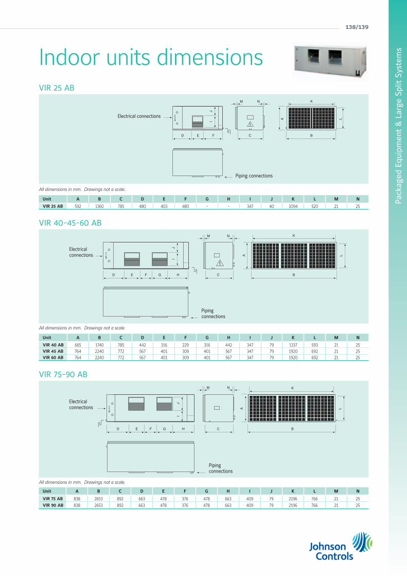
Pack
aged
Equ
ipm
ent
& L
arge
Spl
it S
yste
ms
138/139
All dimensions in mm. Drawings not a scale.
VIR 25 AB
VIR 40-45-60 AB
VIR 75-90 AB
L
BCD FE
IJ
K
A
M N
Electrical connections
Piping connections
L
BCF G
IJ
ED H
K
A
M N
Electrical connections
Piping connections
Unit A B C D E F G H I J K L M N
VIR 40 AB 665 1740 785 442 316 229 316 442 347 79 1337 593 21 25VIR 45 AB 764 2240 772 567 401 309 401 567 347 79 1920 692 21 25VIR 60 AB 764 2240 772 567 401 309 401 567 347 79 1920 692 21 25
Unit A B C D E F G H I J K L M N
VIR 25 AB 592 1360 785 480 403 480 - - 347 40 1094 520 21 25
Unit A B C D E F G H I J K L M N
VIR 75 AB 838 2653 892 663 478 376 478 663 409 79 2196 766 21 25VIR 90 AB 838 2653 892 663 478 376 478 663 409 79 2196 766 21 25
All dimensions in mm. Drawings not a scale.
All dimensions in mm. Drawings not a scale.
Electrical connections L
BCF HG
JI
ED
A
KM N
Piping connections
Indoor units dimensions
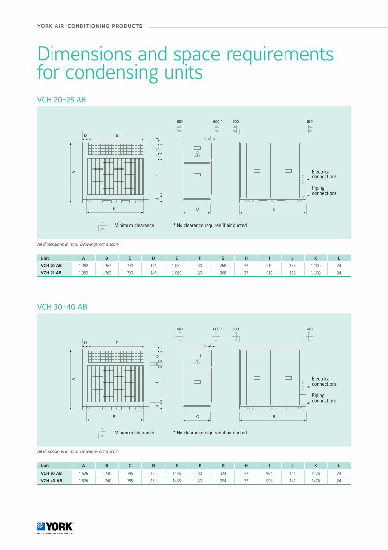
york air-conditioning products
VCH 20-25 AB
Unit A B C D E F G H I J K L
VCH 20 AB 1 392 1 362 790 147 1 069 30 268 37 919 138 1 100 24
VCH 25 AB 1 392 1 362 790 147 1 069 30 268 37 919 138 1 100 24
Unit A B C D E F G H I J K L
VCH 30 AB 1 526 1 740 785 151 1436 30 324 37 994 141 1476 24
VCH 40 AB 1 526 1 740 785 151 1436 30 324 37 994 141 1476 24
A
C
piping
electricalconnections
D E
B
GF
HI
J
K
L
600 *600 600600
All dimensions in mm. Drawings not a scale.
Electrical connections
Piping connections
Minimum clearance * No clearance required if air ducted
A
C
piping
electricalconnections
D E
B
GF
HI
J
K
L
600 *600 600600
Electrical connections
Piping connections
Minimum clearance * No clearance required if air ducted
VCH 30-40 AB
All dimensions in mm. Drawings not a scale.
Dimensions and space requirementsfor condensing units

Pack
aged
Equ
ipm
ent
& L
arge
Spl
it S
yste
ms
140/141
VCH 45-60 AB
All dimensions in mm. Drawings not a scale.
Unit A B C D E F G H I J K L M N
VCH 75 AB 1 794 2658 897 148 1155 95 1155 30 389 37 1 200 138 2479 23
VCH 90 AB 1 794 2658 897 148 1155 95 1155 30 389 37 1 200 138 2479 23
Unit A B C D E F G H I J K L M N
VCH 45 AB 1 641 2 240 778 148 945 95 945 38 389 38 1044 140 2 060 23
VCH 60 AB 1 641 2 240 778 148 945 95 945 38 389 38 1044 140 2 060 23
A
C
piping
electricalconnections
D E
B
IH
JK
L
F G
M
N
600 *600 600600
Electrical connections
Piping connections
Minimum clearance * No clearance required if air ducted
A
C
piping
electricalconnections
D E
B
IH
JK
L
F G
M
N
600 *600 600600
Electrical connections
Piping connections
Minimum clearance * No clearance required if air ducted
VCH 75-90 AB
All dimensions in mm. Drawings not a scale.

york air-conditioning products

142/143
metasys® building automation and control systems
Comprehensive Building Solutions

york air-conditioning products
Metasys® Building Automation and Control Systems
Ease of use • Easy to configure and deploy
• No special training is required to use it
• Enhanced Ready Access Portal (RAP) graphics capability, combined with the tenant user setup capabilities, deliver targeted views of data to any building occupants. It’s also now compatible with Apple iPhone® or iPod® Touch platforms.
More efficiency, less costs • The Energy Essentials leverages the Metasys® Advanced Reporting System to take the existing data and present it in an organized and informative way, providing easy-to-configure, easy-to-use and actionable energy reports
• The improved Johnson Controls Central Plant Optimization™ 10 (CPO 10) helps facility managers operate their chiller plants more efficiently. CPO algorithms are used to operate and sequence plant equipment in an efficient and reliable manner, and to ensure that runtime, starts and stops are equalized across the individual plant components saving energy and improving reliability in the facility.
Metasys® building management system from Johnson Controls ensures all of the building systems – comfort controls, lighting, fire safety, security and HVAC equipment – operate together in harmony. With an innovative, IT-based infrastructure, software and wireless capabilities, Metasys® is the one building management system that coordinates and organizes all the information logically to deliver it where and when needed, giving more control and easier access to information than any other system of its kind.
Already the winner of the 2009 Frost & Sullivan North American BAS Market Leadership Award, Metasys® now offers even more.

Manufacturer reserves the rights to change specifications without prior notice.
144/145
Com
preh
ensi
ve B
uild
ing
Solu
tion
sC
ompr
ehen
sive
Bui
ldin
g So
lution
s
Single platform communication • Enhanced, single platform interface of thousands of different hardwired and wireless systems, devices and equipment.
• Even more control options and better information access by users, thanks to:
• Field Equipment Controllers redesigning• Terminal Equipment Controller updates and improvements • Added wireless and network sensors• Enhanced software and firmware
Wireless Capabilities • Increased control flexibility, streamlines retrofits and faster download times, thanks to the latest wireless technologies that Metasys® incorporates into more devices.
• At system’s user interface, network automation, field controller or room sensing levels, Wireless Building Technologies from Johnson Controls always result in increased application flexibility and cost effectiveness.
Security features • Metasys® now incorporates P2000 Security Management System, whose software and network controllers ensure the safety of employees and security of company assets.
• P2000 open integration platform, designed for interoperability with a variety of security subsystems including access control, alarm & intrusion detection, video surveillance, visitor management.
P2000Badging Station
RS485 / IPConverter
2 DoorsController
S321
P2000Server
CCTV
CK721Up to 16Readers
S300S300
P2000Work Station
Intrusion DVN 5000
IP Network

CD Rom 2012 :Commercial Leaflets, Technical Library, Software Tools and more...

Multi-language Technical Information
easy-direct-clear
Minimum system requirements• Operating system Windows 98 or better• Pentium II processor or superior• 32 MB of RAM• Screen resolution 800 x 600 pixels, 16 bits
To view all pdf files, the Adobe Acrobat Reader© program is required. If said program is not installed, install the one included in this CD-ROM.
CD available at Johnson Controls
office
Residential & Light Commercial 2012york air-conditioning products m-cd-g2012

E-CAT-LC-G2012http://www.johnsoncontrols.co.uk
About Johnson Controls
Johnson Controls delivers products, services and solutions that increase energy efficiency and lower operating costs in buildings for more than one million customers.
Operating from 500 branch offices in more than 150 countries, the company is a leading provider of equipment, controls and services for heating, ventilating, air-conditioning, refrigeration and security systems. Johnson Controls is involved in more than 500 renewable energy projects including solar, wind and geothermal technologies.
Its solutions have reduced carbon dioxide emissions by 13.6 million metric tons and generated savings of $7.5 billion since 2000. Many of the world’s largest companies rely on Johnson Controls to manage 1.5 billion square feet of their commercial real estate.
www.johnsoncontrols.com© Johnson Controls, 2012
PUBL-6912
Johnson Controls reserve the right, in line with continuing research and development, to amend or change specifications without notice.