


Languages
Pages
Legal


Product Specification
XL270
Power SuppliesDocument No. 706601 Rev 07
Product Specification
XL270 Series 270-Watt AC to DC
Power Supplies Document No. 706601 Rev 07-01-19

706601 Rev 07-01-19 i
Notices
N2Power is a wholly owned subsidiary of Qualstar Corporation.
N2Power and the N2Power logo are registered trademarks of Qualstar Corporation.
Copyright© 2017 by Qualstar Corporation — All Rights Reserved
For warranty information refer to http://www.qualstar.com/n2p-pss.php
Information contained in this document is copyrighted by Qualstar Corporation and is
intended for use by customers and prospective customers to evaluate and integrate
our power supplies. Customers and prospective customers may reproduce this
document as needed for these purposes. Reproduction in whole or in part for any other
purpose or by any other party is prohibited without prior written permission from
Qualstar Corporation.
Every effort has been made to keep the information contained in this document
current and accurate as of the date of publication or revision. However, no guarantee
is given or implied that the document is error-free or that it is accurate with regard to
any specification.
N2Power reserves the right to modify the design or specification without notice. This
specification may not be construed as a contractual obligation except as specifically
agreed to by N2Power in writing at the time of order.
For information about this product specification, please write or call N2Power at:
N2Power A Subsidiary of Qualstar Corp.
1267 Flynn Road Camarillo, CA 93012
FAX: (805) 978-5212
Phone: (805) 583-7744
E-Mail: [email protected] www.qualstar.com/n2p-pss.php
706601 Rev 07-01-19 ii
Table of Contents
1. Introduction ................................................................................................................... 1-1
1.1 Introduction .................................................................................................................... 1-1
1.2 Agency Compliance ........................................................................................................ 1-2
2. AC Input .......................................................................................................................... 2-1
2.1 Input Line Requirements .............................................................................................. 2-1
2.2 Input Over Current Protection ...................................................................................... 2-1
2.3 Inrush Current Limiting ............................................................................................... 2-1
2.4 Low Input Voltage .......................................................................................................... 2-1
2.5 Touch Current ................................................................................................................ 2-2
2.6 Power Factor................................................................................................................... 2-2
2.7 Safety Warning .............................................................................................................. 2-3
3. DC Output ....................................................................................................................... 3-1
3.1 Output Voltage Regulation ............................................................................................ 3-1
3.2 Common Return ............................................................................................................. 3-1
3.3 No Load Operation ......................................................................................................... 3-1
3.4 Overshoot at Turn On/Turn Off .................................................................................... 3-1
3.5 Output Current/Power ................................................................................................... 3-2
3.6 Efficiency ........................................................................................................................ 3-2
3.7 Unloaded Power Consumption ...................................................................................... 3-3
3.8 Cooling ............................................................................................................................ 3-3
3.9 Output Ripple/Noise ...................................................................................................... 3-4
3.10 Local and Remote Sensing (RS) ................................................................................ 3-5
3.11 Parallel Operation ..................................................................................................... 3-6
3.12 Power Supply Protection ........................................................................................... 3-8
3.13 Output Transients ..................................................................................................... 3-9
3.14 Capacitive Loading .................................................................................................. 3-10
4. General Specifications ................................................................................................ 4-1
4.1 Environmental................................................................................................................ 4-1
4.2 Mean Time Between Failures ....................................................................................... 4-1
4.3 Component Stress .......................................................................................................... 4-1
4.4 Labeling/Marking ........................................................................................................... 4-2
4.5 Physical Dimensions ...................................................................................................... 4-2
4.6 Weight ............................................................................................................................. 4-3
4.7 Mating Connectors ......................................................................................................... 4-3
4.8 Signal Descriptions and Remarks ................................................................................. 4-6
706601 Rev 07-01-19 iii
5. Timing and Control ...................................................................................................... 5-1
5.1 Power Supply Timing ..................................................................................................... 5-1
5.2 Power Good Output ........................................................................................................ 5-1
5.3 Remote Enable Input ..................................................................................................... 5-2
5.4 Hold-Up Time ................................................................................................................. 5-2
5.5 Output Rise Time ........................................................................................................... 5-2
5.6 LED Indicators ............................................................................................................... 5-2
6. Ordering Information .................................................................................................. 6-1
706601 Rev 07-01-19
1.
1.1 Introduction
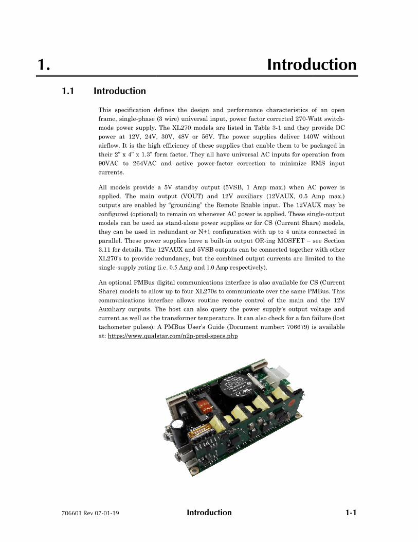
This specification defines the design and performance characteristics of an open
frame, single-phase (3 wire) universal input, power factor corrected
mode power supply. The XL
power at 12V, 24V,
airflow. It is the high efficiency of these supplies that enable the
their 2” x 4” x 1.3” form factor. They all have universal AC inputs
90VAC to 264VAC
currents.
All models provide a
applied. The main
outputs are enabled by
configured (optional)
models can be used as stand
they can be used in redundant or
parallel. These power supp
3.11 for details. The 12V
XL270’s to provide redundancy, but the
single-supply rating
An optional PMBus digital communications interface is also available
Share) models to allow up to four XL270s to communicate over the same PMBus. This
communications interface allows routine remote control of the main and the 12V
Auxiliary outputs. The host can also query the power supply’s output voltage and
current as well as the tran
tachometer pulses). A PMBus User’s Guide
at: https://www.qualstar.com/n2p
Introduction
Introduction
This specification defines the design and performance characteristics of an open
phase (3 wire) universal input, power factor corrected 270-W
mode power supply. The XL270 models are listed in Table 3-1 and they provide
, 30V, 48V or 56V. The power supplies deliver 140
It is the high efficiency of these supplies that enable them to be packaged in
” form factor. They all have universal AC inputs for operation from
VAC and active power-factor correction to minimize RMS
models provide a 5V standby output (5VSB, 1 Amp max.) when AC power is
output (VOUT) and 12V auxiliary (12VAUX, 0.5 Amp max.)
abled by “grounding” the Remote Enable input. The 12VAUX
(optional) to remain on whenever AC power is applied. These single
models can be used as stand-alone power supplies or for CS (Current Share)
can be used in redundant or N+1 configuration with up to 4 units connected in
These power supplies have a built-in output OR-ing MOSFET – see Section
The 12VAUX and 5VSB outputs can be connected together with other
s to provide redundancy, but the combined output currents are limited to the
(i.e. 0.5 Amp and 1.0 Amp respectively).
An optional PMBus digital communications interface is also available for CS
to allow up to four XL270s to communicate over the same PMBus. This
communications interface allows routine remote control of the main and the 12V
Auxiliary outputs. The host can also query the power supply’s output voltage and
current as well as the transformer temperature. It can also check for a fan failure (lost
tachometer pulses). A PMBus User’s Guide (Document number: 706679) is available
https://www.qualstar.com/n2p-prod-specs.php
1-1
Introduction
This specification defines the design and performance characteristics of an open
Watt switch-
provide DC
140W without
m to be packaged in
operation from
RMS input
when AC power is
Amp max.)
AUX may be
These single-output
Current Share) models,
with up to 4 units connected in
see Section
together with other
limited to the
for CS (Current
to allow up to four XL270s to communicate over the same PMBus. This
communications interface allows routine remote control of the main and the 12V
Auxiliary outputs. The host can also query the power supply’s output voltage and
sformer temperature. It can also check for a fan failure (lost
is available

706601 Rev 07-01-19
1.2 Agency Compliance
The XL270 complies with the following international agency standards:
Safety Complies with Standard
United States UL 60950-1 Second Edition
UL 62368-1 Second Edition
(Information Technology Equipment)
Canada CSA 22.2: 60950
EU Council 2006/95/EC
International IEC 60950-1 (2005) Second Edition
IEC 62368-1 (2014
EMC Complies with Standard
United States FCC part 15, subpart B
EU Council 2004/108/EC
International EN 61204-3 (refers to the following)
EN 55032 Class
EN 61000 (refers to the following) EN 61000
EN 61000 EN 61000 EN 61000 EN 61000 EN 61000 EN 61000
Reduction of Hazardous Substances (RoHS)
EU Council
Marks of Conformance
United States & Canada
EU Council
RoHS
XL270 Series Product Specification
Introduction
Agency Compliance
complies with the following international agency standards:
Complies with Standard Remarks
Second Edition
1 Second Edition
(Information Technology Equipment)
Touch Current – see table 2-2
Hi-pot – 2121vdc for 1 second Secondary and P.E.)
CSA 22.2: 60950-1
Low Voltage Directive
(2005) Second Edition
2014) Second Edition
Complies with Standard Remarks
15, subpart B Conducted emissions
Limits per CISPR 32 Class A
Tested to ANSI C63.4: 2003
EMC Directive
3 (refers to the following) Low Voltage Power Supplies –
2 Class A Conducted emissions Limits per CISPR 32 Class
(refers to the following) Immunity EN 61000-3-2 Class D Harmonic Current Emissions
(Power Factor Correction EN 61000-3-3 Voltage Fluctuations & EN 61000-4-3 Radiated Susceptibility EN 61000-4-4 Fast Transient/Burst ImmunityEN 61000-4-5 Power Mains Surge ImmunityEN 61000-4-6 RF Immunity EN 61000-4-11 Voltage Dips, Short Interruptions
Reduction of Hazardous Substances (RoHS) Complies with Standard Remarks
2002/95/EC
2011/65/EU
RoHS Directive
RoHS 2 Directive
(Underwriters Laboratories File E211115)
Table 1-1 Agency Compliance
Product Specification
1-2
(Primary to
– DC Output
2 Class A
Harmonic Current Emissions (Power Factor Correction – PFC)
Flicker
Fast Transient/Burst Immunity Power Mains Surge Immunity
Voltage Dips, Short Interruptions
Remarks
RoHS Directive
RoHS 2 Directive

706601 Rev 07-01-19 AC Input 2-1
2. AC Input
2.1 Input Line Requirements
The following table defines the voltage and frequency requirements for the AC line
inputs to the XL270 power supply. The XL270 is capable of supplying full rated power
in continuous operation throughout the specified ranges of voltages and frequencies.
The power supply will automatically recover from AC power loss and is capable of
starting under maximum load at the minimum AC input voltage described below.
Parameter Minimum Rated Maximum
RMS Input Voltage 90 VAC 100 –240VAC 264 VAC
RMS Input Current – – 3.2 A @ 100 V
1.4 A @ 240 V
Input Frequency 47 Hz 50–60 Hz 63 Hz
Table 2-1 XL270 AC Input Parameters
2.2 Input Over Current Protection
The XL270 series incorporates a 6.3A primary AC line fuse for input over current
protection to meet product safety requirements as outlined in Section 1.2.
2.3 Inrush Current Limiting
The cold-start (25° C) inrush current at 90° input phase angle (i.e. AC switch is closed
at the peak of the AC sine wave input) is limited to less than 35 Amps peak for 240
VAC and 18 Amps peak for 120VAC.
Repetitive ON-OFF cycling of the AC input voltage should not damage the power
supply or cause the input fuse to open as long as the AC remains off for more than two
seconds.
2.4 Low Input Voltage
The application of an input voltage below the minimums specified in Table 2-1 shall
not damage the XL270.

706601 Rev 07-01-19
2.5 Touch Current
The current from AC
input voltage and frequency
of multiple power supplies are additive. Consult the appropriate electrical safety
specification for the maximum
will always go to zero when a DPDT switch simultaneously disconnects both the line
and neutral from the power supply
applied to only the Neutral input terminal.
Line VoltageFrequency
120VAC, 60Hz
240VAC, 60Hz
240VAC, 50Hz
Table
2.6 Power Factor
The XL270 power factor exceeds
both 115VAC and 23
XL270 Series Product Specification
AC Input
The current from AC Line or AC Neutral to Protective Earth varies linearly with the
input voltage and frequency (Table 2-2). The touch currents (a.k.a. leakage currents)
multiple power supplies are additive. Consult the appropriate electrical safety
specification for the maximum touch current permitted in your product. Th
will always go to zero when a DPDT switch simultaneously disconnects both the line
from the power supply. A single fault can occur when the AC power is
applied to only the Neutral input terminal.
Voltage Frequency
Operating
Single Fault (see text)
120VAC, 60Hz 0.40 mA 0.75 mA
240VAC, 60Hz 0.80 mA 1.50 mA
240VAC, 50Hz 0.65 mA 1.25 mA
Table 2-2 Touch Current – Single XL270
factor exceeds 0.950 with loads of 135-watts (50%) or greater at
30VAC input voltages. See Figure 2-1 for typical curves.
Figure 2-1 Power Factor, Typical
XL270 Series Product Specification
2-2
Protective Earth varies linearly with the
(a.k.a. leakage currents)
multiple power supplies are additive. Consult the appropriate electrical safety
ermitted in your product. This current
will always go to zero when a DPDT switch simultaneously disconnects both the line
. A single fault can occur when the AC power is
or greater at
1 for typical curves.
XL270 Series Product Specification
706601 Rev 07-01-19 AC Input 2-3
2.7 Safety Warning
WARNING
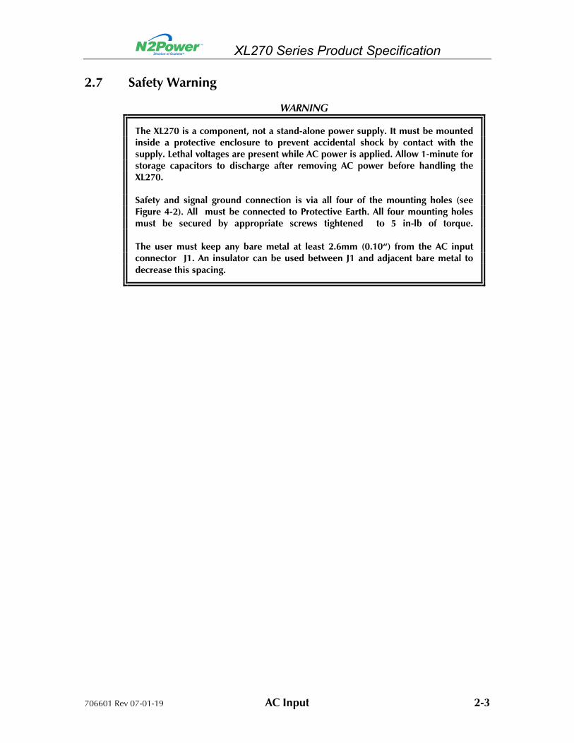
The XL270 is a component, not a stand-alone power supply. It must be mounted inside a protective enclosure to prevent accidental shock by contact with the supply. Lethal voltages are present while AC power is applied. Allow 1-minute for storage capacitors to discharge after removing AC power before handling the XL270.
Safety and signal ground connection is via all four of the mounting holes (see Figure 4-2). All must be connected to Protective Earth. All four mounting holes must be secured by appropriate screws tightened to 5 in-lb of torque. The user must keep any bare metal at least 2.6mm (0.10“) from the AC input connector J1. An insulator can be used between J1 and adjacent bare metal to
decrease this spacing.

706601 Rev 07-01-19 DC Output 3-1
3. DC Output
3.1 Output Voltage Regulation
The DC output voltages shall remain within the limits defined in Table 3-1 when
measured at the power supply connector under all specified conditions contained
herein. Voltage regulation is measured with load currents from zero to the rated load
currents listed in Table 3-2.
Model Output Rated Voltage
Regulation Minimum(VDC)
Rated (VDC)
Maximum (VDC)
RemoteSense
XL270-12 VOUT +12 V ±3% 11.64 12.0 12.36 VOUT/RTN
XL270-24
XL270-30
VOUT
VOUT
+24 V
+30 V
±3%
±3%
23.28
29.10
24.0
30.0
24.72
30.90
VOUT/RTN
VOUT/RTN
XL270-48 VOUT +48 V ±3% 46.56 48.0 49.44 VOUT/RTN
XL270-56 VOUT +56 V ±3% 54.32 56.0 57.68 VOUT/RTN
All 12VAUX +12 V ±5% 11.40 12.0 12.60 N/A
5VSB +5 V ±5% 4.75 5.0 5.25 N/A
Table 3-1 XL270 Output Voltage Specifications
3.2 Common Return
All DC outputs, status outputs and control inputs share a common return (RTN)
found on all output connectors. This return floats with respect to P.E. (Protective
Earth) and is by-passed with a 600V capacitor.
3.3 No Load Operation
A no load condition will not damage the supply or cause a hazardous condition. The
power supply will remain stable and operate normally after application of a load. The
Power Good logic output will indicate normal operation when the supply is unloaded.
3.4 Overshoot at Turn On/Turn Off
The output voltage overshoot upon the application or removal of the AC input voltage
will be less than 5% above the rated voltage. No opposite polarity voltage (with
respect to RTN) will be present on any output during either turn on or turn off.

706601 Rev 07-01-19
3.5 Output Current/Power
The maximum available output power is a function of the airflow and
temperature. The maximum of
available with a minimum of
temperature of 50°C.
watts, 12VAUX is limited to
Model
XL270-
XL270-
XL270-
XL270-
XL270-
All
All
Table 3-2 Maximum Individual
3.6 Efficiency
The power supply efficiency varies with the output
Higher output voltage
(less IR losses). Efficiency dat
airflow, after a 15-minute warm
intervals up to 100%
unloaded. See Figure 3
Figure 3-1 XL
DC Output
Output Current/Power
The maximum available output power is a function of the airflow and
temperature. The maximum of 270-watts combined total power (from all outputs
available with a minimum of 15-CFM of forced airflow up to a maximum ambient
50°C. Each individual output is also limited: VOUT is limited to
is limited to 6W and 5VSB is limited to 5W.
Model Output Rated Voltage
Rated Load
-12 VOUT 12 V 22.5 A
-24
-30
VOUT
VOUT
24 V
30 V
11.3 A
9.0 A
-48 VOUT 48 V 5.7 A
-56 VOUT 56 V 4.9 A
5VSB 5 V 1.0 A
12VAUX 12 V 0.5 A
Maximum Individual Continuous Load Currents
The power supply efficiency varies with the output power and AC input
voltage models tend to exhibit higher efficiencies due to lower currents
(less IR losses). Efficiency data is measured at room temperature with
minute warm-up period. The measurements are taken at 10%
100% rated output power. The 5VSB and 12VAUX outputs
See Figure 3-1 for typical curves.
XL270-12 (12V Model) Typical Efficiency Curves
3-2
The maximum available output power is a function of the airflow and ambient
from all outputs) is
up to a maximum ambient
is limited to 270-
AC input voltage.
exhibit higher efficiencies due to lower currents
with 15-CFM
taken at 10%
outputs are
706601 Rev 07-01-19 DC Output 3-3
3.7 Unloaded Power Consumption
When unloaded with rated input voltage applied, the XL270 will consume about 3W
with the power supply disabled (Remote Enable open) and about 9W under normal
operation, all outputs unloaded.
3.8 Cooling
The XL270 can operate under Convection Cooling at temperatures up to 50°C ambient
temperatures when total power output is less than 140W and the power supply is
mounted open-side up. 15-CFM of airflow is required for an output power up to 270W
in an ambient up to 50°C. The airflow must be either co-planar with the power supply
or impinge downward in the center of the power supply from above. The XL270 may
be mounted in any attitude when 15-CFM airflow is provided.
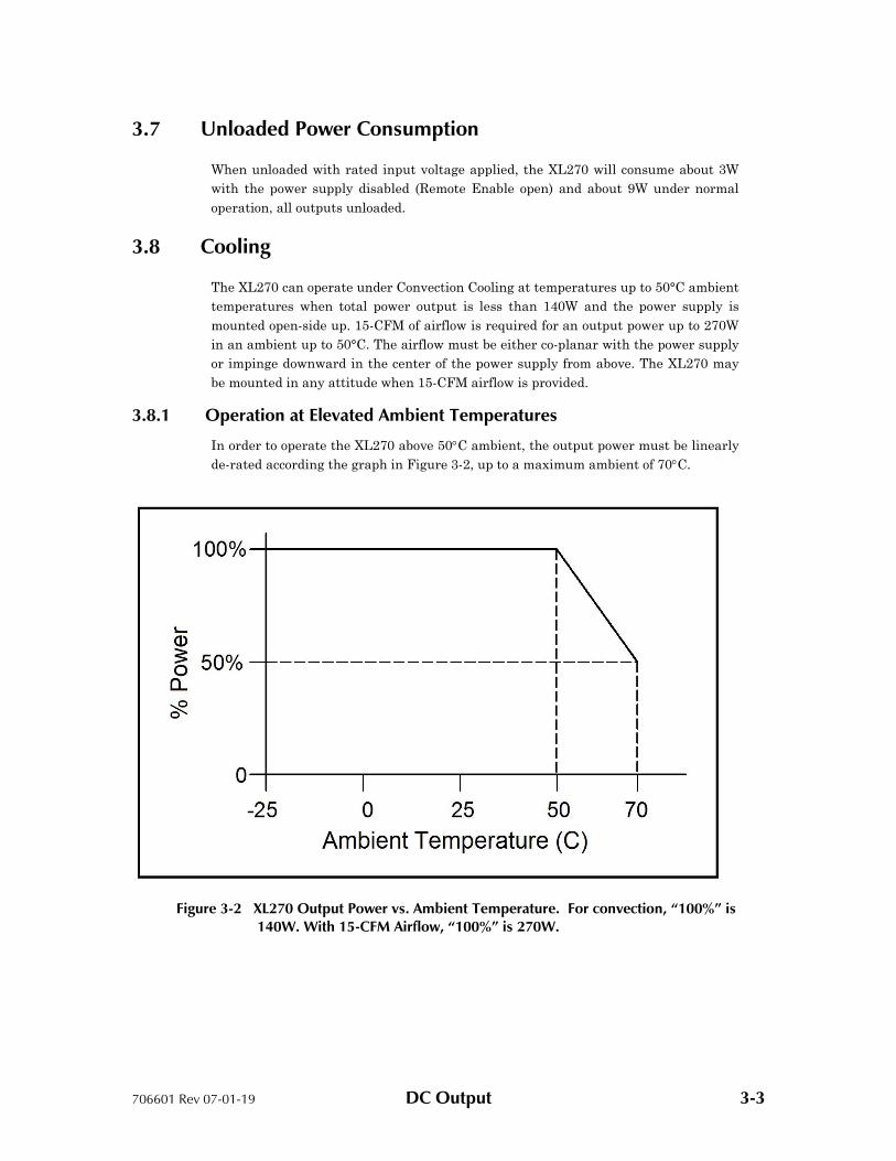
3.8.1 Operation at Elevated Ambient Temperatures
In order to operate the XL270 above 50C ambient, the output power must be linearly
de-rated according the graph in Figure 3-2, up to a maximum ambient of 70C.
Figure 3-2 XL270 Output Power vs. Ambient Temperature. For convection, “100%” is 140W. With 15-CFM Airflow, “100%” is 270W.

706601 Rev 07-01-19 DC Output 3-4
3.8.2 Over Temperature Shutdown
The power supply is equipped with a temperature sensor for self-protection. Failure to
provide adequate airflow, or operation above the specified maximum ambient, will
result in the shutdown of the VOUT and 12VAUX outputs. The 5VSB output remains
operational. The VOUT and 12VAUX outputs will automatically recover when the
temperature of the temperature sensor sufficiently cools.
3.9 Output Ripple/Noise
Output ripple voltage and noise are defined as periodic or random signals over a
frequency band of 10 Hz to 20 MHz Measurements are to be made with an oscilloscope
with a 20 MHz bandwidth. Outputs should be bypassed at the connector with a 0.1 F
ceramic disk capacitor and a 47 F tantalum capacitor to simulate system loading
(Figure 3-3). Ripple and noise (P.A.R.D. ≡ Periodic And Random Deviation) shall not
exceed the limits specified in the following tables.
The ripple voltage of the output is measured at the pins of the mating connector.
Ripple and noise shall not exceed the limits specified in Table 3-3 under any condition
of line voltage and frequency specified in Section 2.1 and DC loading specified in
Section 3.5.
Model Output Rated Voltage
Maximum Ripple+Noise (peak-to-peak)
XL270-12 VOUT 12 V 120 mV
XL270-24
XL270-30
VOUT
VOUT
24 V
30 V
240 mV
300 mV
XL270-48 VOUT 48 V 480 mV
XL270-56 VOUT 56 V 560 mV
All 12VAUX 12 V 120 mV
All 5VSB 5 V 50 mV
Table 3-3 Ripple + Noise Output Voltage
706601 Rev 07-01-19
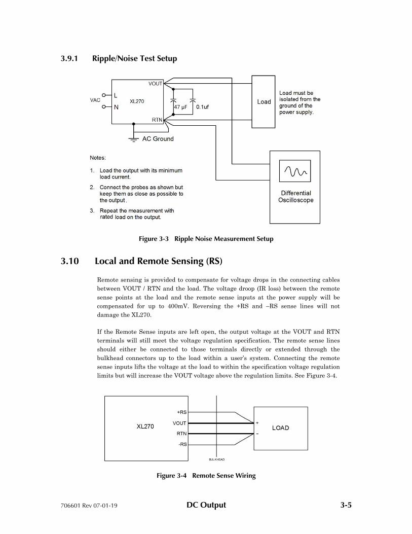
3.9.1 Ripple/Noise Test Setup
Figure
3.10 Local and Remote Sensing
Remote sensing is provided to compensate for voltage drops in the
between VOUT / RTN and the
sense points at the load
compensated for up to 400mV
damage the XL270.
If the Remote Sense inputs are left open, the output voltage at the
terminals will still me
should either be connected to th
bulkhead connectors
sense inputs lifts the voltage a
limits but will increase the V
DC Output
Ripple/Noise Test Setup
Figure 3-3 Ripple Noise Measurement Setup
Local and Remote Sensing (RS)
Remote sensing is provided to compensate for voltage drops in the connecting cables
/ RTN and the load. The voltage droop (IR loss) between the
sense points at the load and the remote sense inputs at the power supply will be
compensated for up to 400mV. Reversing the +RS and –RS sense lines
If the Remote Sense inputs are left open, the output voltage at the VOUT
meet the voltage regulation specification. The remote
connected to those terminals directly or extended through
bulkhead connectors up to the load within a user’s system. Connecting the remote
lifts the voltage at the load to within the specification voltage
increase the VOUT voltage above the regulation limits. See Figure
Figure 3-4 Remote Sense Wiring
47 μF
3-5
connecting cables
loss) between the remote
at the power supply will be
sense lines will not
VOUT and RTN
The remote sense lines
extended through the
to the load within a user’s system. Connecting the remote
voltage regulation
Figure 3-4.
706601 Rev 07-01-19 DC Output 3-6
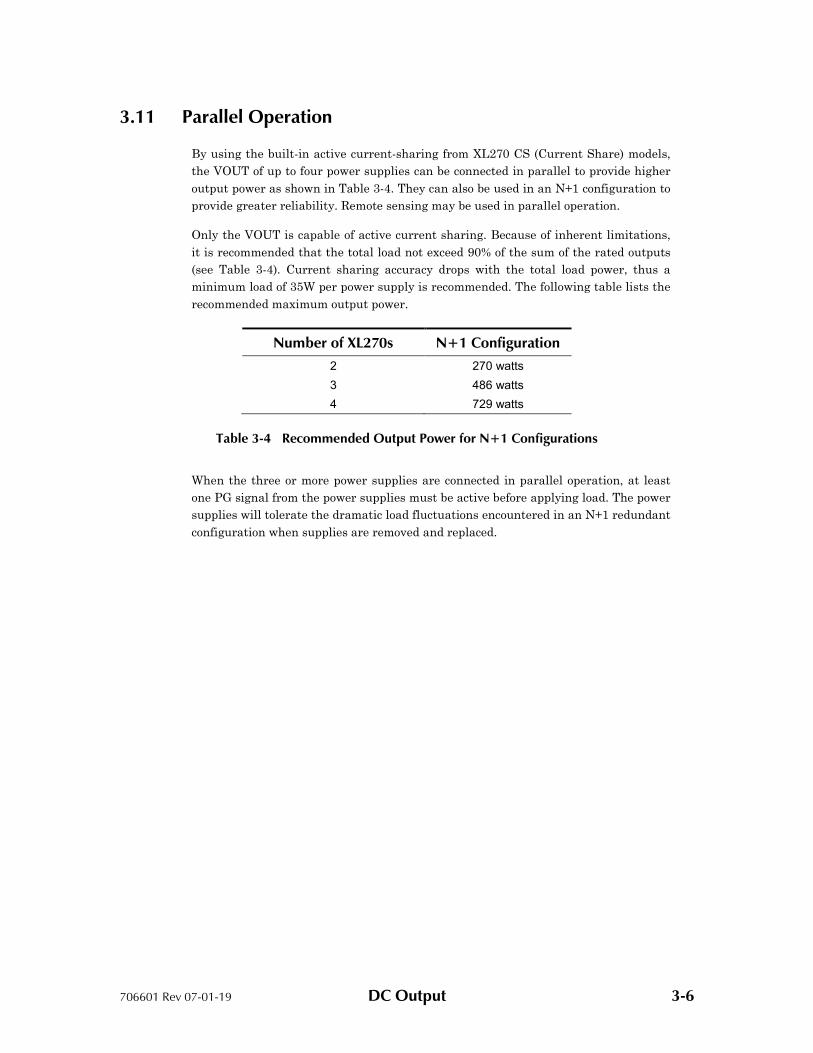
3.11 Parallel Operation
By using the built-in active current-sharing from XL270 CS (Current Share) models,
the VOUT of up to four power supplies can be connected in parallel to provide higher
output power as shown in Table 3-4. They can also be used in an N+1 configuration to
provide greater reliability. Remote sensing may be used in parallel operation.
Only the VOUT is capable of active current sharing. Because of inherent limitations,
it is recommended that the total load not exceed 90% of the sum of the rated outputs
(see Table 3-4). Current sharing accuracy drops with the total load power, thus a
minimum load of 35W per power supply is recommended. The following table lists the
recommended maximum output power.
Number of XL270s N+1 Configuration
2 270 watts
3 486 watts
4 729 watts
Table 3-4 Recommended Output Power for N+1 Configurations
When the three or more power supplies are connected in parallel operation, at least
one PG signal from the power supplies must be active before applying load. The power
supplies will tolerate the dramatic load fluctuations encountered in an N+1 redundant
configuration when supplies are removed and replaced.

706601 Rev 07-01-19 DC Output 3-7
3.11.1 Current Sharing Connections
For the purposes of active current sharing, communication between paralleled
XL270’s is made though the CAN communications interface pins on the J3 option
connector (CAN ≡ Controller Area Network). The CANH (J3-8), CANL (J3-9) and RTN
(J3-6) pins of each power supply must be connected together. Current sharing does not
require the remote sensing, but the sharing accuracy will be enhanced with its use.
See Figure 3-5 below.
Each individual PG/PF signal (J3-10) should be monitored separately by the user
system.
Figure 3-5 Current Share Wiring Example – Two XL270’s.
3.11.2 Current Share Accuracy
When the CAN Bus of all paralleled units are connected together and all the Remote
Sense signals are connected at the regulation point, the current delivered by any of
the sharing supplies will not vary by more than ±5% of IDEAL, at rated current.
Let N = Number of Units in Parallel.
ITOTAL = I1 + I2 +…+ IN
IIDEAL ≡ ITOTAL ÷ N
Error = Ik – IIDEAL, where Ik is the k-th unit’s current
%Error = [(IK – IIDEAL) ÷ IIDEAL] X 100%
Sharing accuracy deteriorates with decreasing load current.

706601 Rev 07-01-19 DC Output 3-8
3.11.3 5V Standby Parallel Operation
For parallel operation, each 5VSB requires a series diode (a schottky, supplied by
customer, is recommended) placed between the output and the load for isolation.
Configured this way, the 5VSB will remain active so long as one of the paralleled
supplies is functioning. As stated before, the total current rating may not go beyond
the single supply rating.
3.11.4 12V Auxiliary Parallel Operation
The 12VAUX requires a series diode as described in 3.11.3.
3.11.5 Output Rise Times
The output rise time and monotonic requirements of 5.5 may not be met when the
paralleled units are powered up into a load that exceeds 270-watts. This is due to
differing in start-up times of the paralleled power supplies.
3.12 Power Supply Protection
There are several different protection circuits designed to protect the load and the
XL270 from component failures and extraordinary circumstances.
3.12.1 Over Temperature Protection (OTP)
If the XL270 is operated without adequate cooling, it will sense an over-temperature
condition and shut down the VOUT and 12VAUX outputs. It will restart after it has
cooled down to below its maximum operating temperature. The PF/PG signal and
LED go false about 2ms before the V1 output is disabled. The V2 and V3 outputs are
unaffected by a V1 OTP condition.
3.12.2 Over-Voltage Protection (OVP)
Only VOUT provides Over-Voltage Protection. When an over-voltage occurs
(nominally at 120% of rated output voltage with an acceptable range of 115% - 125%),
the power supply will shut down and latch off. The AC input will need to be cycled
OFF-ON for recovery.
When OVP is triggered, the 12VAUX will be disabled but the 5VSB will continue to
function. The XL270 will shut down under the following over voltage conditions:

706601 Rev 07-01-19 DC Output 3-9
Table 3-5 Over Voltage Protection Limits
3.12.3 Over Current Protection (OCP)
An over-load on the VOUT will induce constant-current limiting which will cause the
output voltage to fall. The constant-current limit has a threshold of 115% (± 5%) of the
rated output current. The VOUT current-limit is not affected by the loading on 5VSB
and 12VAUX.
During OCP an under-voltage detector (UVD) turns off the Power Good output signal
and LED before the output voltage falls below 83% of rated and restores them to the
on state before the output voltage rises above 86%.
The under-voltage protection (UVP) circuit will shut the output off when the output
voltage falls below about 67%. The XL270 will attempt to restart approximately 6-
seconds after the UVP event. If the load current is low enough to allow the output
voltage to exceed 67%, the supply will remain on. If not, it will attempt to restart
every 6 seconds.
3.12.4 Short Circuit Protection (SCP)
A short circuit on VOUT will disable the output but not damage the XL270. A short on
the 12VAUX output will disable all outputs. The XL270 will periodically attempt to
restart until the short circuit condition is removed. After successfully restarting, the
power supply will operate normally.
3.13 Output Transients
The maximum output voltage transient caused by step load changes will not exceed
the output voltage regulation limits by more than 5%. With an AC input as specified
in Section 2.1, the power supply will remain stable when subjected to the load
transients described below with capacitive loading per Table 3-6:
Load changes between 75% and 100% on any output
Load changing repetition of 50 to 333 cycles per second
Transient load slew rate = 1 A / us
Model VOUT Minimun Nominal Maximum
XL270-12 12V 13.8V 14.4V 15.0V
XL270-24
XL270-30
24V
30 V
27.6V
34.5V
28.8V
36.0V
30.0V
37.5V
XL270-48 48V 55.2V 57.6V 60.0V
XL270-56 56V 58.0V 59.0V 60.0V
706601 Rev 07-01-19 DC Output 3-10
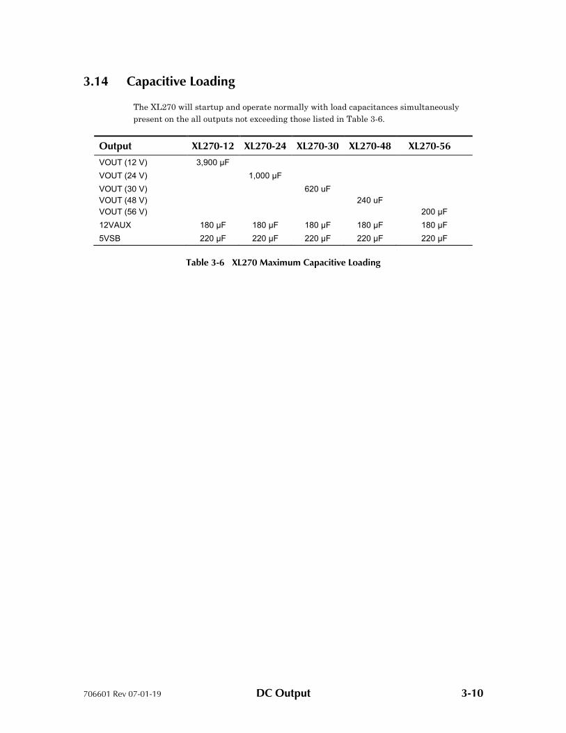
3.14 Capacitive Loading
The XL270 will startup and operate normally with load capacitances simultaneously
present on the all outputs not exceeding those listed in Table 3-6.
Output XL270-12 XL270-24 XL270-30 XL270-48 XL270-56
VOUT (12 V) 3,900 μF
VOUT (24 V) 1,000 μF
VOUT (30 V)
VOUT (48 V)
VOUT (56 V)
620 uF
240 uF
200 μF
12VAUX 180 μF 180 μF 180 μF 180 μF 180 μF
5VSB 220 μF 220 μF 220 μF 220 μF 220 μF
Table 3-6 XL270 Maximum Capacitive Loading
706601 Rev 07-01-19 General Specifications 4-1
4. General Specifications
4.1 Environmental
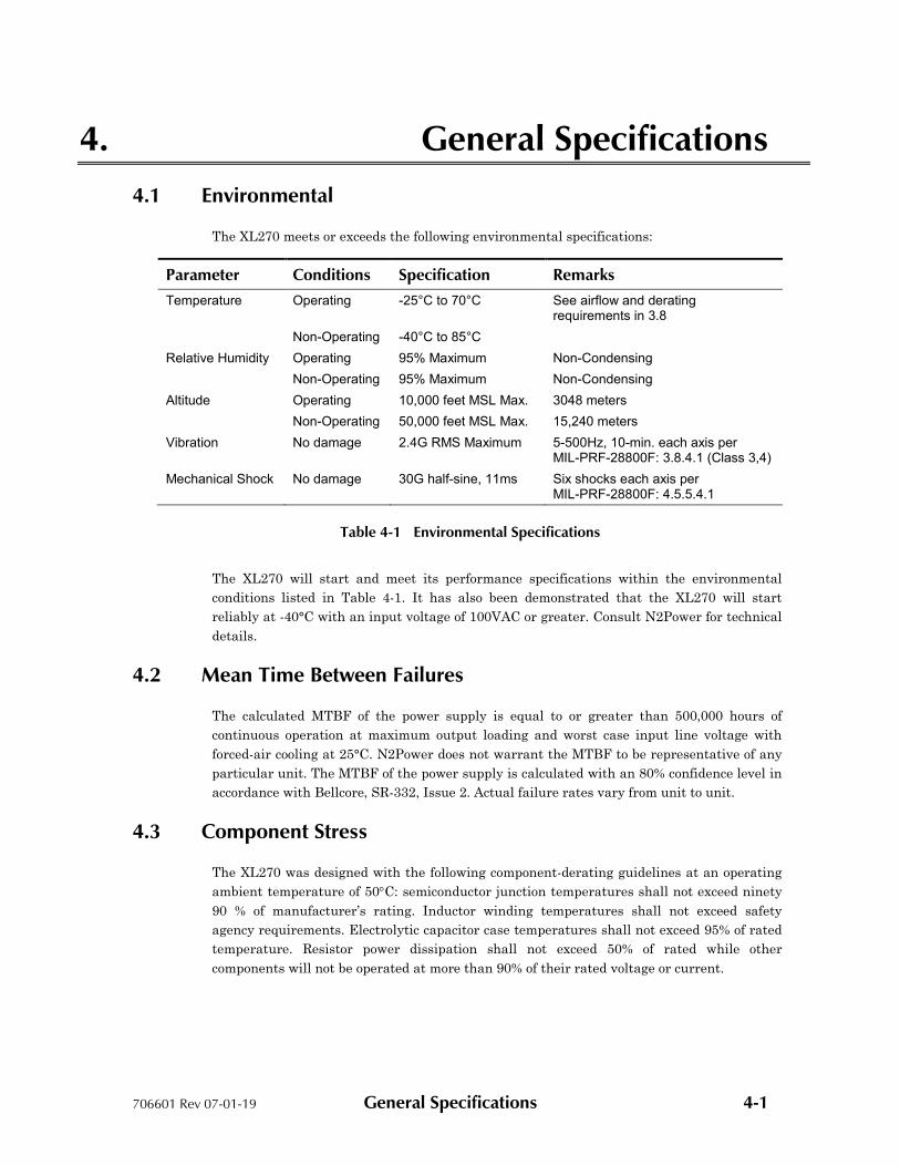
The XL270 meets or exceeds the following environmental specifications:
Parameter Conditions Specification Remarks
Temperature Operating -25°C to 70°C See airflow and derating requirements in 3.8
Non-Operating -40°C to 85°C
Relative Humidity Operating 95% Maximum Non-Condensing
Non-Operating 95% Maximum Non-Condensing
Altitude Operating 10,000 feet MSL Max. 3048 meters
Non-Operating 50,000 feet MSL Max. 15,240 meters
Vibration No damage 2.4G RMS Maximum 5-500Hz, 10-min. each axis per MIL-PRF-28800F: 3.8.4.1 (Class 3,4)
Mechanical Shock No damage 30G half-sine, 11ms Six shocks each axis per MIL-PRF-28800F: 4.5.5.4.1
Table 4-1 Environmental Specifications
The XL270 will start and meet its performance specifications within the environmental
conditions listed in Table 4-1. It has also been demonstrated that the XL270 will start
reliably at -40°C with an input voltage of 100VAC or greater. Consult N2Power for technical
details.
4.2 Mean Time Between Failures
The calculated MTBF of the power supply is equal to or greater than 500,000 hours of
continuous operation at maximum output loading and worst case input line voltage with
forced-air cooling at 25°C. N2Power does not warrant the MTBF to be representative of any
particular unit. The MTBF of the power supply is calculated with an 80% confidence level in
accordance with Bellcore, SR-332, Issue 2. Actual failure rates vary from unit to unit.
4.3 Component Stress
The XL270 was designed with the following component-derating guidelines at an operating
ambient temperature of 50C: semiconductor junction temperatures shall not exceed ninety
90 % of manufacturer’s rating. Inductor winding temperatures shall not exceed safety
agency requirements. Electrolytic capacitor case temperatures shall not exceed 95% of rated
temperature. Resistor power dissipation shall not exceed 50% of rated while other
components will not be operated at more than 90% of their rated voltage or current.

706601 Rev 07-01-19
4.4 Labeling/Marking
The power supply is marked and
number, input and output specifications, production code, appropriate safety agency logos,
CE mark, and country of origin. A
4.5 Physical Dimensions
General Specifications
Labeling/Marking
The power supply is marked and labelled with the N2Power logo model number, part
number, input and output specifications, production code, appropriate safety agency logos,
CE mark, and country of origin. An example label is pictured below.
Figure 4-1 Sample XL270 Label
Physical Dimensions
Figure 4-2 XL270 Series Dimensions
Protected Earth Ground (4 places)
LEDs indicators
4-2
with the N2Power logo model number, part
number, input and output specifications, production code, appropriate safety agency logos,
Protected Earth Ground
LEDs indicators
706601 Rev 07-01-19 General Specifications 4-3
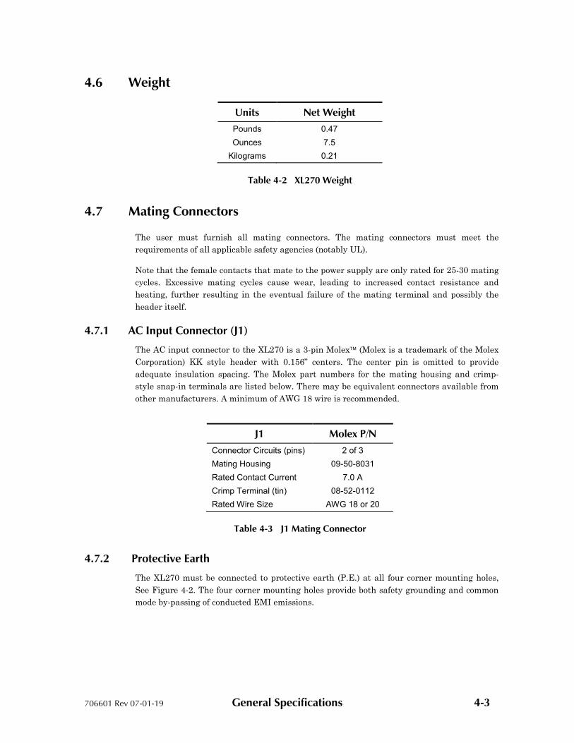
4.6 Weight
Units Net Weight
Pounds 0.47
Ounces 7.5
Kilograms 0.21
Table 4-2 XL270 Weight
4.7 Mating Connectors
The user must furnish all mating connectors. The mating connectors must meet the
requirements of all applicable safety agencies (notably UL).
Note that the female contacts that mate to the power supply are only rated for 25-30 mating
cycles. Excessive mating cycles cause wear, leading to increased contact resistance and
heating, further resulting in the eventual failure of the mating terminal and possibly the
header itself.
4.7.1 AC Input Connector (J1)
The AC input connector to the XL270 is a 3-pin Molex (Molex is a trademark of the Molex
Corporation) KK style header with 0.156” centers. The center pin is omitted to provide
adequate insulation spacing. The Molex part numbers for the mating housing and crimp-
style snap-in terminals are listed below. There may be equivalent connectors available from
other manufacturers. A minimum of AWG 18 wire is recommended.
J1 Molex P/N
Connector Circuits (pins) 2 of 3
Mating Housing 09-50-8031
Rated Contact Current 7.0 A
Crimp Terminal (tin) 08-52-0112
Rated Wire Size AWG 18 or 20
Table 4-3 J1 Mating Connector
4.7.2 Protective Earth
The XL270 must be connected to protective earth (P.E.) at all four corner mounting holes,
See Figure 4-2. The four corner mounting holes provide both safety grounding and common
mode by-passing of conducted EMI emissions.
706601 Rev 07-01-19 General Specifications 4-4
4.7.3 Output Terminals (VOUT and RTN)
The DC output terminals for VOUT are designed to accept a ring-lug terminal. There are
many sources available. A minimum of AWG 16 wire is recommended. The lugs must have a
minimum I.D. of 0.140” [3.53mm] and a maximum O.D. of 0.32” [8.1mm]. The lugs must be
contaminant free and should be tightened to a torque of approximately 8-inch-pounds [0.9 N-
m]. These terminals use 6-32 UNC screws.
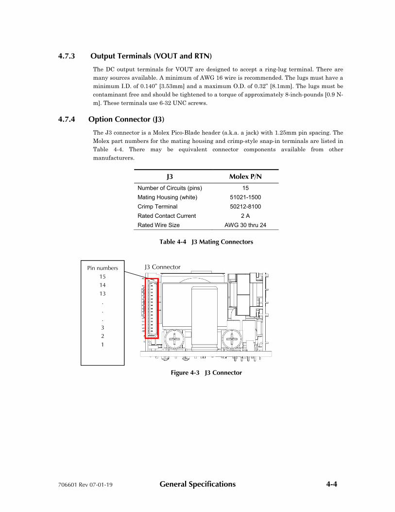
4.7.4 Option Connector (J3)
The J3 connector is a Molex Pico-Blade header (a.k.a. a jack) with 1.25mm pin spacing. The
Molex part numbers for the mating housing and crimp-style snap-in terminals are listed in
Table 4-4. There may be equivalent connector components available from other
manufacturers.
J3 Molex P/N
Number of Circuits (pins) 15
Mating Housing (white) 51021-1500
Crimp Terminal 50212-8100
Rated Contact Current 2 A
Rated Wire Size AWG 30 thru 24
Table 4-4 J3 Mating Connectors
Figure 4-3 J3 Connector
Pin numbers
15
14
13
.
.
.
3
2
1
J3 Connector Pin numbers
15
14
13
.
.
.
3
2
1
Pin numbers
15
14
13
.
.
.
3
2
1

706601 Rev 07-01-19 General Specifications 4-5
4.7.5 Auxiliary/Standby Output Connector (J6)
The J6 connector is a Molex Micro-Latch header (a.k.a. a jack) with 2mm pin spacing. The
Molex part numbers for the mating housing and crimp-style snap-in terminals are listed in
Table 4-4. There may be equivalent connector components available from other
manufacturers.
J6 Molex P/N
Number of Circuits (pins) 5
Mating Housing (white) 51065-0500
Crimp Terminal 50212-8100
Rated Contact Current 2 A
Rated Wire Size AWG 30 thru 24
Table 4-5 J6 Mating Connectors
Figure 4-4 J6 Connector
Pin numbers 1 2 3 4 5

706601 Rev 07-01-19 General Specifications 4-6
4.8 Signal Descriptions and Remarks
Signal Description/Remarks
AC Line (L1) Highest in potential compared to earth ground. Should be connected to the AC power switch.
AC Neutral (L2) Closest in potential to earth ground. Should not be connected to a single-pole power switch.
RTN / DC Return (ground)
XL270 circuit return for all outputs and status/control signals.
VOUT The main output (+)
I2C Serial Clock Optional: Provides PMBus control/status interface. Pulled-up to 3.3V by a 4.7K resistor. Maximum frequency is 100Khz.
I2C Serial Data Optional: Provides PMBus control/status interface. Pulled-up to 3.3V by a 4.7K resistor.
Address 1 High-true address selection input (2 bits: 0,1).
Address 0 High-true address selection input (2 bits: 0,1).
CAN HIGH HIGH data line for CAN (Controller area Network) communications (for current sharing and service use)
CAN LOW LOW data line for CAN (Controller area Network) communications (for current sharing and service use)
-RS Remote sense for RTN
+RS Remote sense for VOUT (compensates for load-cable drop)
PF/PG A high-logic level (≈4.5V) indicates the output power is in regulation for at least the next 2ms.
RE Remote Enable Input
12V Auxiliary (12VAUX) / FAN Controlled Output
Provides 0.5A at 12V. Uses RTN for its return.
With the PMBus command, this output can switch on and off with a preprogrammed duty cycle to control fan speed.
5VSB Provides 1A at 5V. Uses RTN for its return.
Tachometer Input The tachometer output of a single fan may be connected to this input. The loss of the tachometer signal is detected and can be reported over the optional serial data interface.
Table 4-6 Signal Descriptions and Remarks

706601 Rev 07-01-19 General Specifications 4-7
Pin Signal Name
J1-1 VAC Neutral Input (L2)
J1-2 No Pin (open)
J1-3 VAC Line Input (L1)
Pin Signal Name
J2-1,J2-2 Jumper for Gateway application
Pin Signal Name
N/A VOUT (Positive with respect to RTN)
N/A RTN (Main Output Return)
Pin Signal Name
J3-1 I2C Serial Clock
J3-2 I2C Serial Data
J3-3 Address 1 Input (A0, see below)
J3-4 Address 0 Input (A1, see below)
J3-5 Return (RTN)
J3-6 Return (RTN)
J3-7 CAN High (CANH) (for Current Sharing)
J3-8 CAN High (CANH) (for Current Sharing)
J3-9 CAN Low (CANL) (for Current Sharing)
J3-10 CAN Low (CANL) (for Current Sharing)
J3-11 Negative Remote Sense (-RS)
J3-12 Positive Remote Sense (+RS)
J3-13 Power Fail/Power Good (PF/PG)
J3-14 Remote Enable (ENABLE)
J3-15 Not used
Pin Signal Name
J6-1 Return (RTN)
J6-2 5V Standby (5VSB)
J6-3 Return (RTN)
J6-4 12V Auxiliary (12VAUX) / FAN Controlled Output
J6-5 Tachometer Input
Table 4-7 Connector Pin Assignments
706601 Rev 07-01-19 Timing and Control 5-1
5. Timing and Control
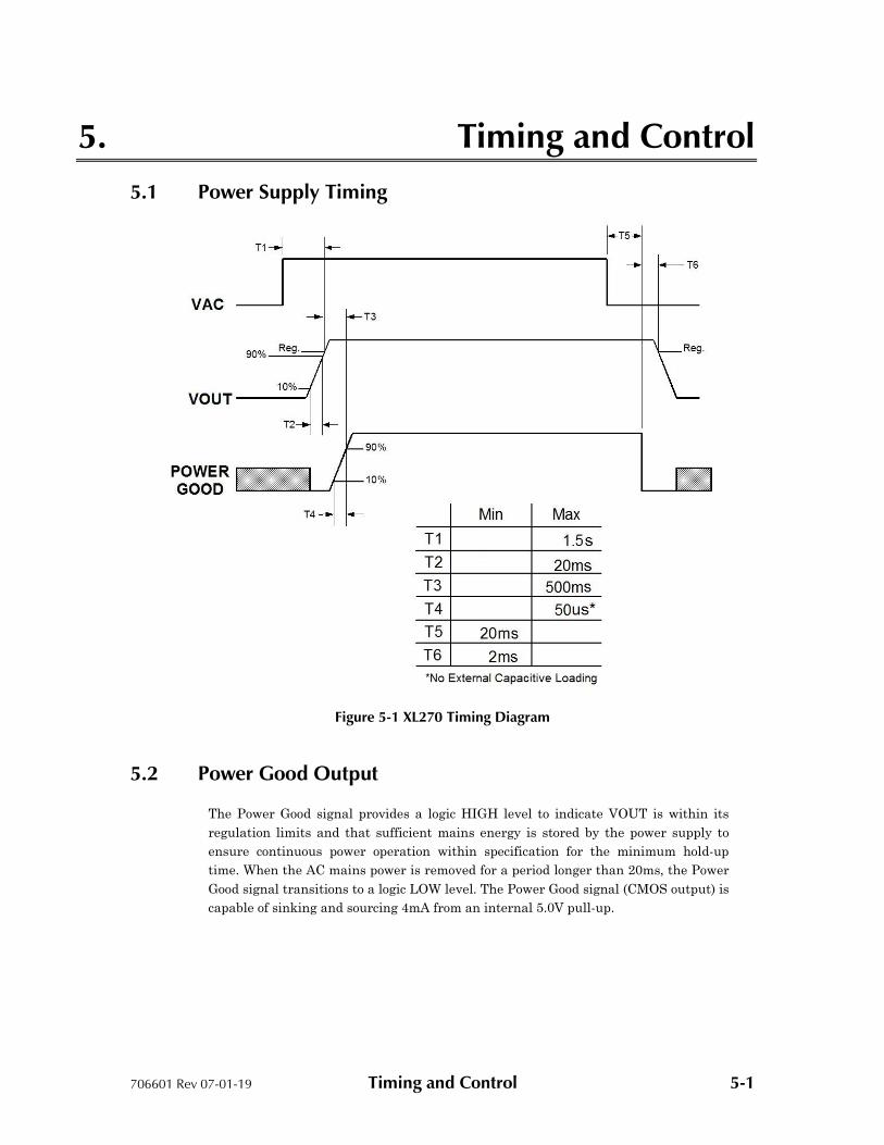
5.1 Power Supply Timing
Figure 5-1 XL270 Timing Diagram
5.2 Power Good Output
The Power Good signal provides a logic HIGH level to indicate VOUT is within its
regulation limits and that sufficient mains energy is stored by the power supply to
ensure continuous power operation within specification for the minimum hold-up
time. When the AC mains power is removed for a period longer than 20ms, the Power
Good signal transitions to a logic LOW level. The Power Good signal (CMOS output) is
capable of sinking and sourcing 4mA from an internal 5.0V pull-up.

706601 Rev 07-01-19 Timing and Control 5-2
5.3 Remote Enable Input
This input is normally floating to enable VOUT. It must be connected to RTN to
disable VOUT. It has no effect on the 5V stand-by, or the 12V auxiliary. It is
internally pulled-up to 3.3V through a 10kΩ resistor. External voltage may be applied
to this input to control VOUT. The input voltage must be less than 0.2V in order to
disable VOUT and greater than 2.0V (up to 3.3V) to enable it.
5.4 Hold-Up Time
The power supply will maintain output regulation per Table 3-1 despite a loss of input
power at 100VAC/50Hz and 230VAC/50Hz at maximum rated continuous output for a
minimum of 22ms.
5.5 Output Rise Time
All outputs from the XL270 shall rise monotonically from 10% to 90% of their rated
output voltage (Table 3 1) within 0.2ms to 20ms under any loading conditions (Table
3-2). The voltage rise of two or more XL270s operating in parallel may not be
monotonic.
5.6 LED Indicators
There are two LED indicators mounted near the top of the control board behind J5
(See Figure 4-2). A green LED illuminates whenever the Power Good signal is true
(high). This indicates the main output is on and regulating. A red LED indicates a
problem with the unit.

706601 Rev 07-01-19 Ordering Information 6-1
6. Ordering Information
The following table provides the N2Power part numbers that should appear on your
purchase order and will appear on any N2Power correspondence:
Model Number V1
XL270 N2Power
Part Number
XL270-12 12 V 400075-01-6
XL270-24
XL270-30
24 V
30 V
400075-02-4
400075-03-3
XL270-48 48 V 400075-05-7
XL270-56 56 V 400075-07-3
XL270-12 CS 12 V 400075-09-9
XL270-24 CS 24 V 400075-10-7
XL270-30 CS 30 V 400075-11-5
XL270-48 CS 48 V 400075-13-1
XL270-56 CS 56 V 400075-15-6
Table 6-1 XL270 Part Numbers
For warranty information refer to http://www.qualstar.com/n2p-pss.php
All XL270 power supplies are RoHS compliant.
Direct all questions, orders or requests for quotation as follows:
N2Power Order Desk: [email protected]
805-583-7744 x112
Fax (Attention N2Power): 805-978-5212
Sales: [email protected]
805-583-7744 x122
Technical Support [email protected]
805-583-7744 x119
Street Address: 1267 Flynn Road
Camarillo, CA 93012
Top Related