


Languages
Pages
Legal


White Paper March 2006 A quick-guide to 802.16e radio-planning with ICS telecom
Emmanuel Grenier
Fixed
Nomadic
Mobile
Software solutions in radiocommunications

Abstract This white paper provides a radio-planning workflow for WiMax technologies with ICS telecom.
It focuses not only on fixed and nomadic WiMax that have heavily being tested and deployed all
over the world, but also provides dedicated planning methodologies for mobile WiMAX. Since the
early ratification of the 802.16e standard by IEEE, WiMAX becomes eventually mobile, enabling
roaming between cells.
The provided workflow is divided in three parts :
The coverage model allows the user to dimension its WiMax network.
The capacity model will ensure that the WiMAX BS won't be overloaded due to the traffic
requests of the CPEs or Mobile Units.
The spectrum model will minimize the interference areas, and update the achievable traffic
in the WiMAX network designed.
References
WiMAX Forum: Mobile WiMAX -- Part I: A Technical Overview and Performance Evaluation
ATDI (Daniel Humire-EG) : A brief overview of 802.16e specific features and current developments for
simulating a WiMAX Network with ICS telecom
WiMAX forum : WiMAX application usage profile (AWG Application Traffic Model and Usage Profile -
Sub team) Intel© Corporation : RF systems and circuit challenges for WiMAX
J.H. Stott : How and why OFDM
brief overview
2
Table of Content
1 Required components __________________________________________________________ 1
1.1 Cartography ____________________________________________________________ 2
1.2 Network components _____________________________________________________ 3
2 Project setup _________________________________________________________________ 4
3 The Base Stations network _____________________________________________________ 5
3.1 Import _________________________________________________________________ 5
3.2 Optimize the base station locations __________________________________________ 6
4 The WiMAX coverage _________________________________________________________ 9
4.1 802.16 Propagation _______________________________________________________ 9
4.2 Coverage calculation _____________________________________________________ 10
4.3 Filtering the best BS locations _____________________________________________ 11
4.4 Sectorizing the Base Stations and analyze the coverage ________________________ 12
5 WiMAX Capacity analysis _____________________________________________________ 13
5.1 Bit rate / modulation map ________________________________________________ 13
5.2 The WiMAX CPE _______________________________________________________ 14 5.2.1 Radiation pattern _____________________________________________________ 15
5.2.2 The 802.16 parenting according to the Service Flows ________________________ 15
5.2.3 QoS curve according to the contention ratio ________________________________ 21
6 WiMAX Spectrum analysis ____________________________________________________ 22
6.1 FWA-type analysis ______________________________________________________ 22 6.1.1 Coverage mode ______________________________________________________ 22
6.1.2 PMP interference ____________________________________________________ 26
7 Mobility analysis ____________________________________________________________ 27
7.1 Delay spread ___________________________________________________________ 27
7.2 Hand-over maps ________________________________________________________ 28 7.2.1 Fast Base Station Switching ____________________________________________ 28
7.2.2 Hard handover _______________________________________________________ 30
7.3 Hand-over along a mobile path ____________________________________________ 30
8 WiMAX radio-planning : a workflow with ICS telecom _____________________________ 31

1
1
1/35
A QUICK-GUIDE TO 802.16E RADIO-PLANNING WITH ICS TELECOM
Note : all provided values are FOR IN FORMATION ONLY
1 Required components
In order to perform an accurate WiMAX radio-planning of fixed, nomadic type or mobile type, ICS telecom
requires several inputs such as digital cartography, technical parameters of the equipment(s) you
want to simulate, having a good knowledge of the minimum Quality of Service you want to ensure, as well
as being aware of the spectrum available.
Different 802.16 profiles
Different types of WiMAX

2
2
2/35
1.1 Cartography
The choice of the cartography to use depends on the type of WiMAX radio-planning to perform :
Large scale WiMAX networks would require Medium Resolution cartography
Close range WiMAX network analysis would require High resolution cartography.
HR cartography
MR cartography
Low resolution data Medium resolution data High resolution data
Typical
content DTM at 500m
. DTM at 30m
. Clutter file giving different
urban and vegetation heights as
aggregates
. Topographic map
. DTM at 2m
. Building height file at 2m
. Type of building map at 2m
. True-orthophoto
Typical use
Not advised because of
the lack of accuracy of
the cartography
Network dimensioning
Capacity and QoS analysis of an
entire network
Interchannel interference
between the Base Stations
Handover map of the network
High-end OFDM coverage of a
few base stations
Detailed throughput and
interference analysis on a hot-
spot
Different cartographic datasets for different planning methodologies
3
3
3/35
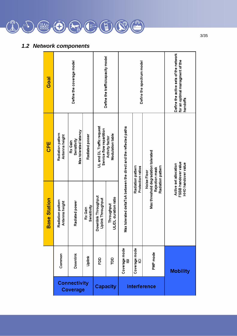
1.2 Network components
4
4
4/35
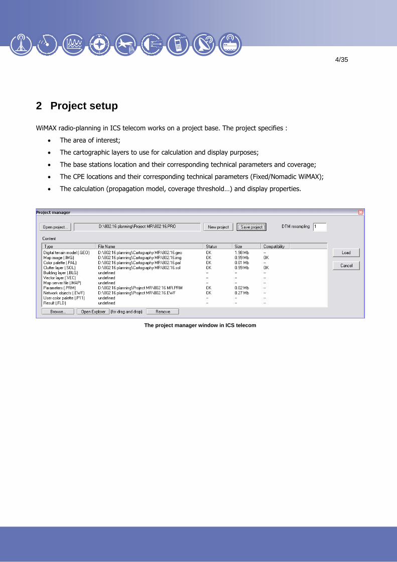
2 Project setup
WiMAX radio-planning in ICS telecom works on a project base. The project specifies :
The area of interest;
The cartographic layers to use for calculation and display purposes;
The base stations location and their corresponding technical parameters and coverage;
The CPE locations and their corresponding technical parameters (Fixed/Nomadic WiMAX);
The calculation (propagation model, coverage threshold…) and display properties.
The project manager window in ICS telecom

5
5
5/35
3 The Base Stations network
3.1 Import
There are number of ways to add a base station on the map :
Manually
Using coordinates
Adding a site using its coordinates
Import from an Excel spreadsheet
Import of a site list from a spreadsheet
Connection to an ODBC/ADO compliant exchange table (Access©, Oracle©, Foxpro©…)
Integration of ICS telecom into an ODBC/DAO compliant database management software

6
6
6/35
3.2 Optimize the base station locations
ICS telecom features different ways to find the best locations for a WiMAX BS (Identification of the highest
point in a given area, site searching from the prospected CPE locations..).
One way to proceed would be to display on top of the Area of Interest a pattern of hexagonal shapes, and to
place an omni-directionnal BS in the center of each cell.
WiMAX Macrocell technical parameters
Raw distribution of the WiMAX macrocells in ICS telecom

7
7
7/35
The size of the cell should be smaller than the expected coverage range.
Downlink – 3 sectors
Uplink – 3 sectors
Downlink - Omni Uplink - Omni
As a worst case scenario, defining a cell pattern of 2 km in a urban area guarantees on a good theoretical
coverage, including the relevant fade margin.
8
8
8/35
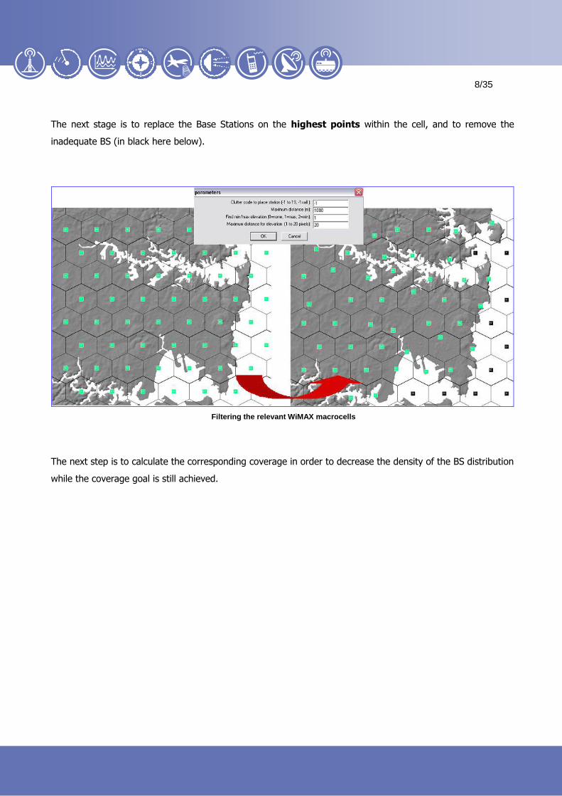
The next stage is to replace the Base Stations on the highest points within the cell, and to remove the
inadequate BS (in black here below).
Filtering the relevant WiMAX macrocells
The next step is to calculate the corresponding coverage in order to decrease the density of the BS distribution
while the coverage goal is still achieved.
9
9
9/35
4 The WiMAX coverage
4.1 802.16 Propagation
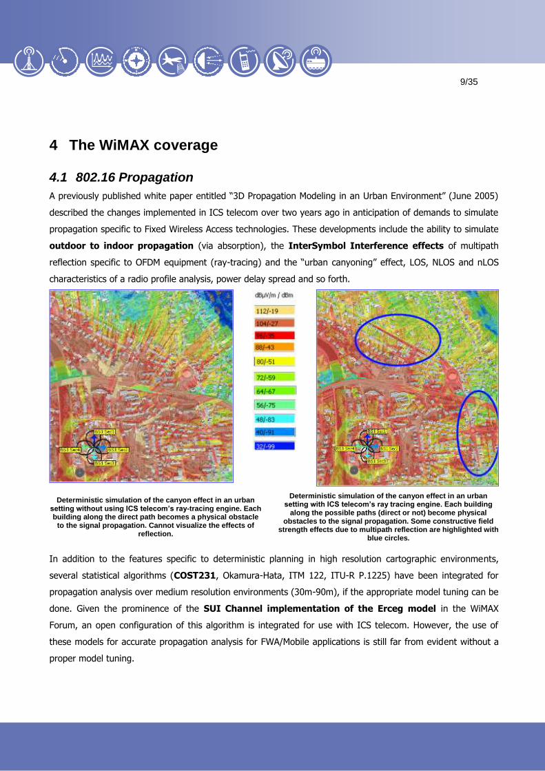
A previously published white paper entitled “3D Propagation Modeling in an Urban Environment” (June 2005)
described the changes implemented in ICS telecom over two years ago in anticipation of demands to simulate
propagation specific to Fixed Wireless Access technologies. These developments include the ability to simulate
outdoor to indoor propagation (via absorption), the InterSymbol Interference effects of multipath
reflection specific to OFDM equipment (ray-tracing) and the “urban canyoning” effect, LOS, NLOS and nLOS
characteristics of a radio profile analysis, power delay spread and so forth.
Deterministic simulation of the canyon effect in an urban setting without using ICS telecom’s ray-tracing engine. Each building along the direct path becomes a physical obstacle
to the signal propagation. Cannot visualize the effects of reflection.
Deterministic simulation of the canyon effect in an urban setting with ICS telecom’s ray tracing engine. Each building
along the possible paths (direct or not) become physical obstacles to the signal propagation. Some constructive field
strength effects due to multipath reflection are highlighted with blue circles.
In addition to the features specific to deterministic planning in high resolution cartographic environments,
several statistical algorithms (COST231, Okamura-Hata, ITM 122, ITU-R P.1225) have been integrated for
propagation analysis over medium resolution environments (30m-90m), if the appropriate model tuning can be
done. Given the prominence of the SUI Channel implementation of the Erceg model in the WiMAX
Forum, an open configuration of this algorithm is integrated for use with ICS telecom. However, the use of
these models for accurate propagation analysis for FWA/Mobile applications is still far from evident without a
proper model tuning.
10
10
10/35
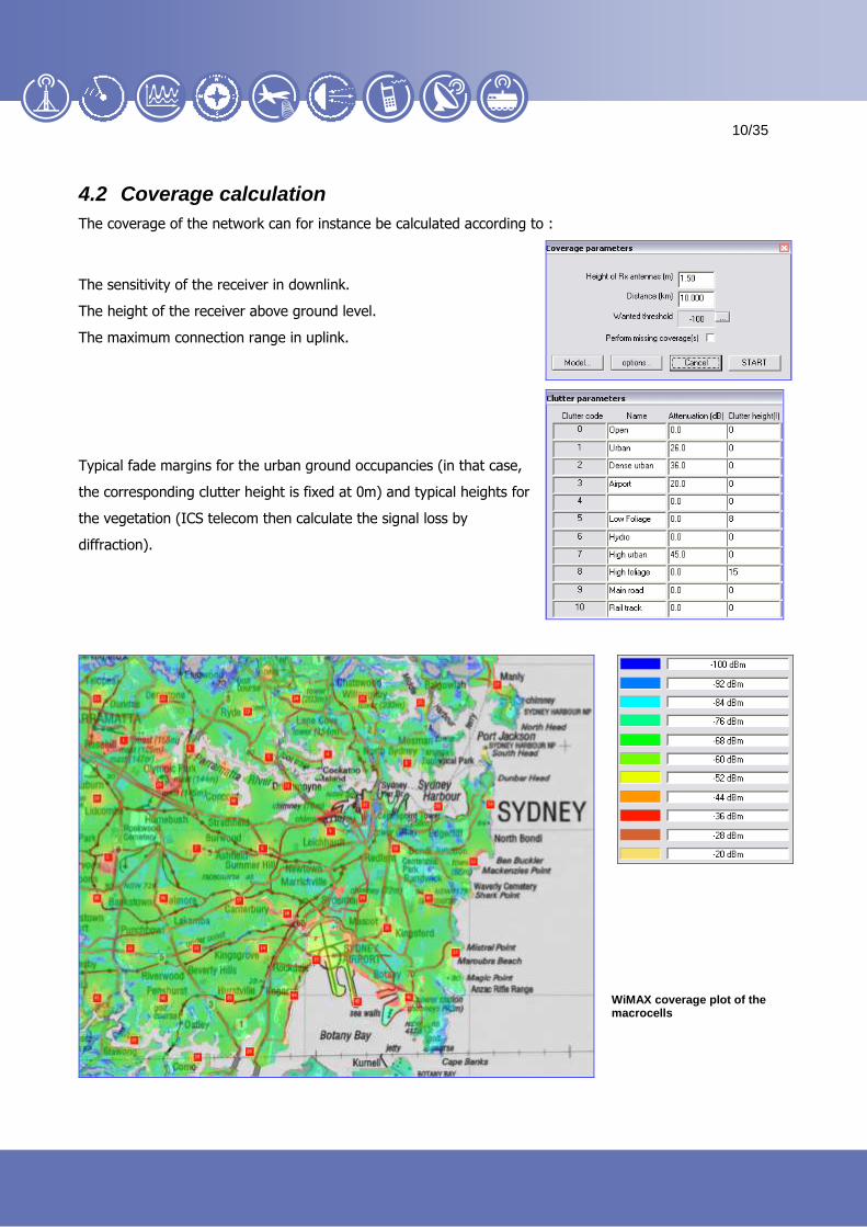
4.2 Coverage calculation
The coverage of the network can for instance be calculated according to :
The sensitivity of the receiver in downlink.
The height of the receiver above ground level.
The maximum connection range in uplink.
Typical fade margins for the urban ground occupancies (in that case,
the corresponding clutter height is fixed at 0m) and typical heights for
the vegetation (ICS telecom then calculate the signal loss by
diffraction).
WiMAX coverage plot of the macrocells

11
11
11/35
4.3 Filtering the best BS locations
ICS telecom can then select among this site list the BS covering the largest area and the most interesting
ground occupancies.
Selected sites
Removed sites
WiMAX coverage plot of the
most relevant macrocells

12
12
12/35
4.4 Sectorizing the Base Stations and analyze the coverage
Once the best site locations have been found, the BS can be sectorized (for fixed/nomadic WiMax).
Omni-directional 3 Sectors 4 Sectors
Coverage map (Omni-directional)
Best Server map (Omni-directional)
Coverage map (Tri-sectorial) Best Server map (Tri-sectorial)

13
13
13/35
5 WiMAX Capacity analysis
5.1 Bit rate / modulation map
A first stage is to display a map of the achievable bit rates according to the power received. Typical
values are given here below :
Typical sensitivities in fixed mode:
Traffic map (raw bit rates) of a fixed/nomadic WiMAX network in ICS telecom
14
14
14/35
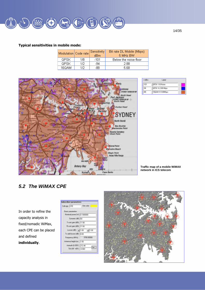
Typical sensitivities in mobile mode:
Traffic map of a mobile WiMAX network in ICS telecom
5.2 The WiMAX CPE
In order to refine the
capacity analysis in
fixed/nomadic WiMax,
each CPE can be placed
and defined
individually.

15
15
15/35
5.2.1 Radiation pattern
Each WiMAX CPE is configured using its corresponding radiation pattern.
It can be a standard antenna, or being adaptive (better connectivity, with
more resistance with regards to the interference).
5.2.2 The 802.16 parenting according to the Service Flows
5.2.2.1 Throughput at the BS level
The user can make the choice between TDD or FDD type of equipment. The way the BS throughput is
managed is different.
For FDD systems, the user can specify one throughput value for the downlink, and one for the uplink.
Base Station
CPEs
16
16
16/35
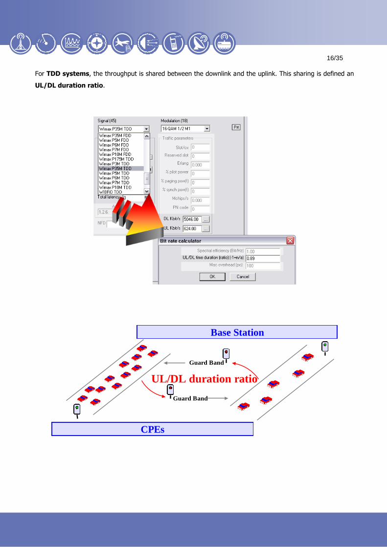
For TDD systems, the throughput is shared between the downlink and the uplink. This sharing is defined an
UL/DL duration ratio.
Base Station
Guard Band
Guard Band
CPEs
UL/DL duration ratio
17
17
17/35
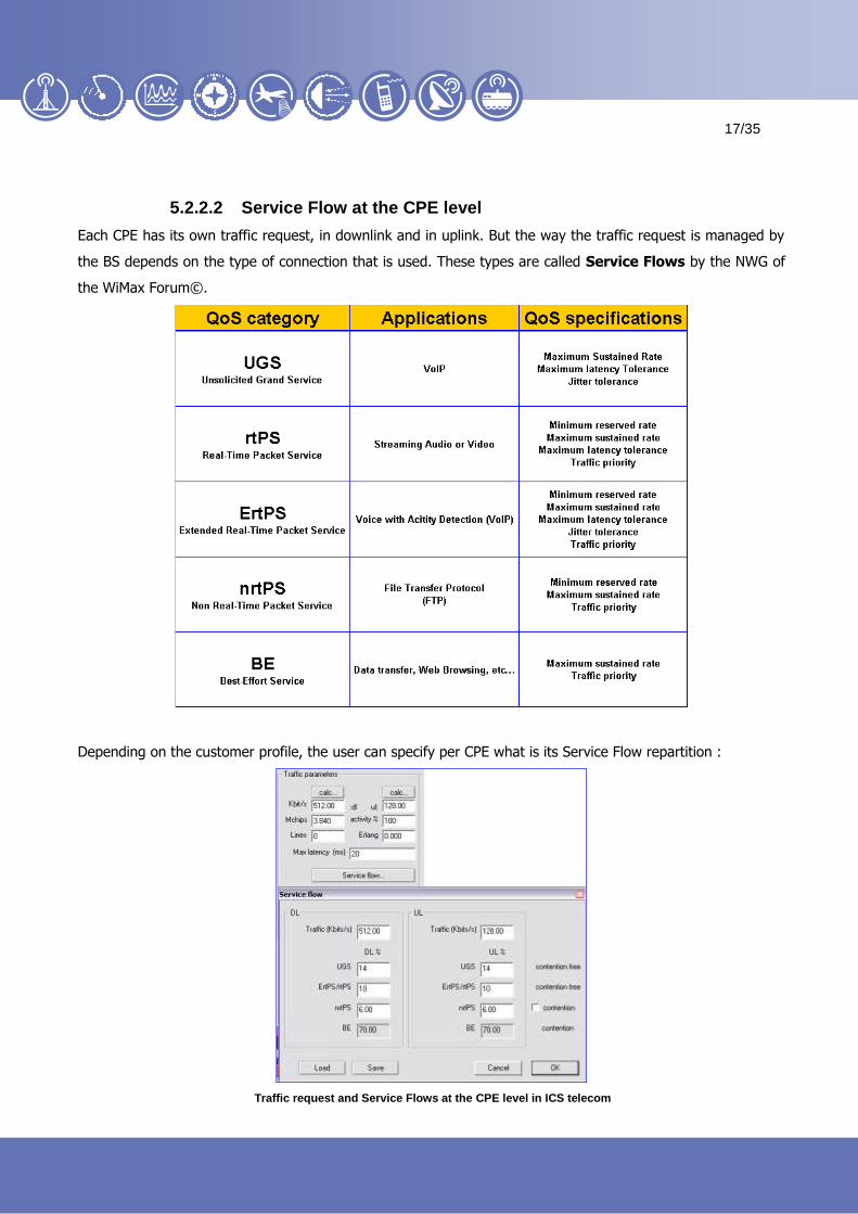
5.2.2.2 Service Flow at the CPE level
Each CPE has its own traffic request, in downlink and in uplink. But the way the traffic request is managed by
the BS depends on the type of connection that is used. These types are called Service Flows by the NWG of
the WiMax Forum©.
Depending on the customer profile, the user can specify per CPE what is its Service Flow repartition :
Traffic request and Service Flows at the CPE level in ICS telecom

18
18
18/35
5.2.2.3 The service Flow parenting
Once the user has defined the available throughput available at the BS level, and the traffic/service flow
requests at the CPEs level, a very detailed QoS analysis can be performed.
Parenting 802.16 CPEs in ICS telecom
The 802.16 parenting checks :
The priorities between the service flows
The fact that the service flows might be contention free (UGS, rtPS…) or contention based (BE)
The parenting in DL, then in UL
The maximum tolerable latency between the end user and the source of the signal
The contention ratio of each CPE
19
19
19/35
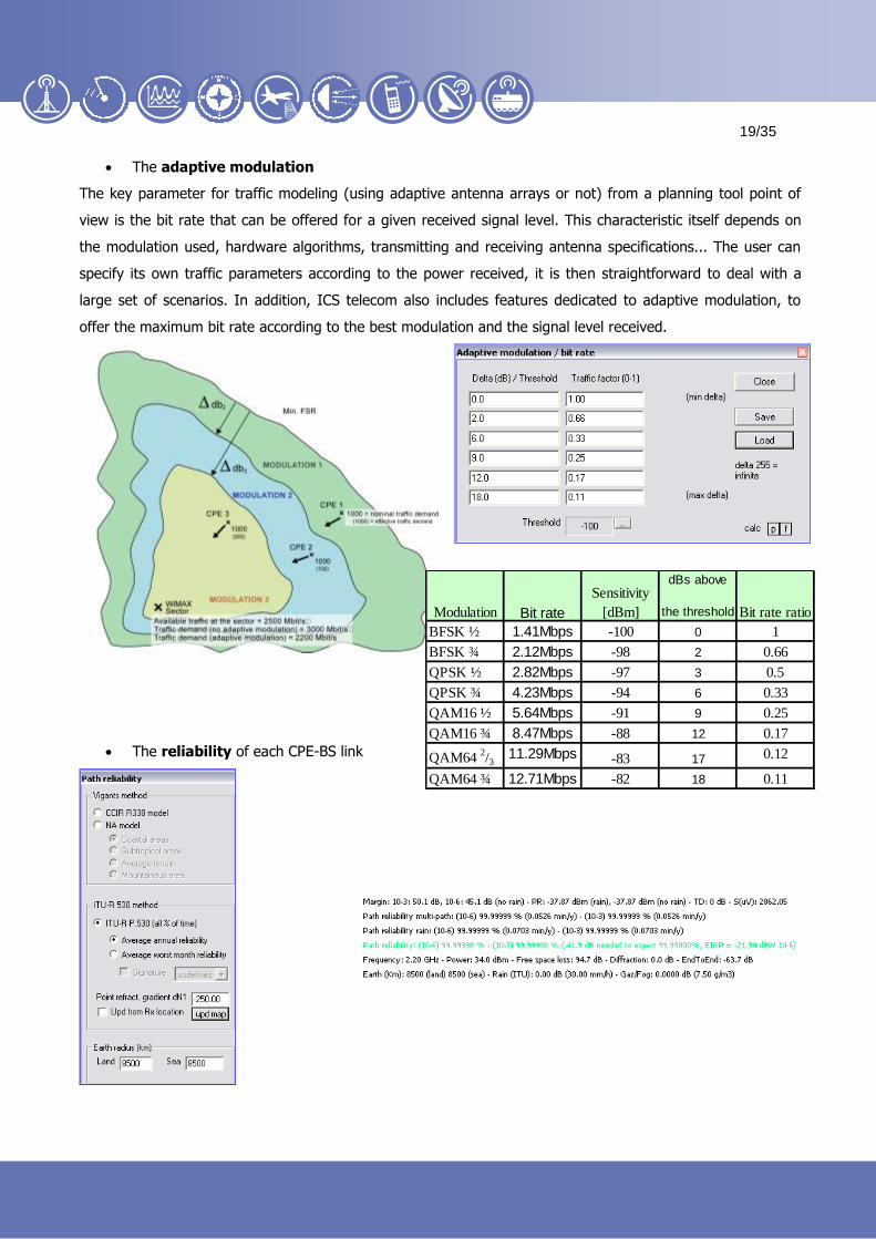
The adaptive modulation
The key parameter for traffic modeling (using adaptive antenna arrays or not) from a planning tool point of
view is the bit rate that can be offered for a given received signal level. This characteristic itself depends on
the modulation used, hardware algorithms, transmitting and receiving antenna specifications... The user can
specify its own traffic parameters according to the power received, it is then straightforward to deal with a
large set of scenarios. In addition, ICS telecom also includes features dedicated to adaptive modulation, to
offer the maximum bit rate according to the best modulation and the signal level received.
The reliability of each CPE-BS link
dBs above
the threshold
BFSK ½ 1.41Mbps -100 0 1
BFSK ¾ 2.12Mbps -98 2 0.66
QPSK ½ 2.82Mbps -97 3 0.5
QPSK ¾ 4.23Mbps -94 6 0.33
QAM16 ½ 5.64Mbps -91 9 0.25
QAM16 ¾ 8.47Mbps -88 12 0.17
QAM64 2/3
11.29Mbps -83 17 0.12
QAM64 ¾ 12.71Mbps -82 18 0.11
Modulation Bit rate
Sensitivity
[dBm] Bit rate ratio
20
20
20/35
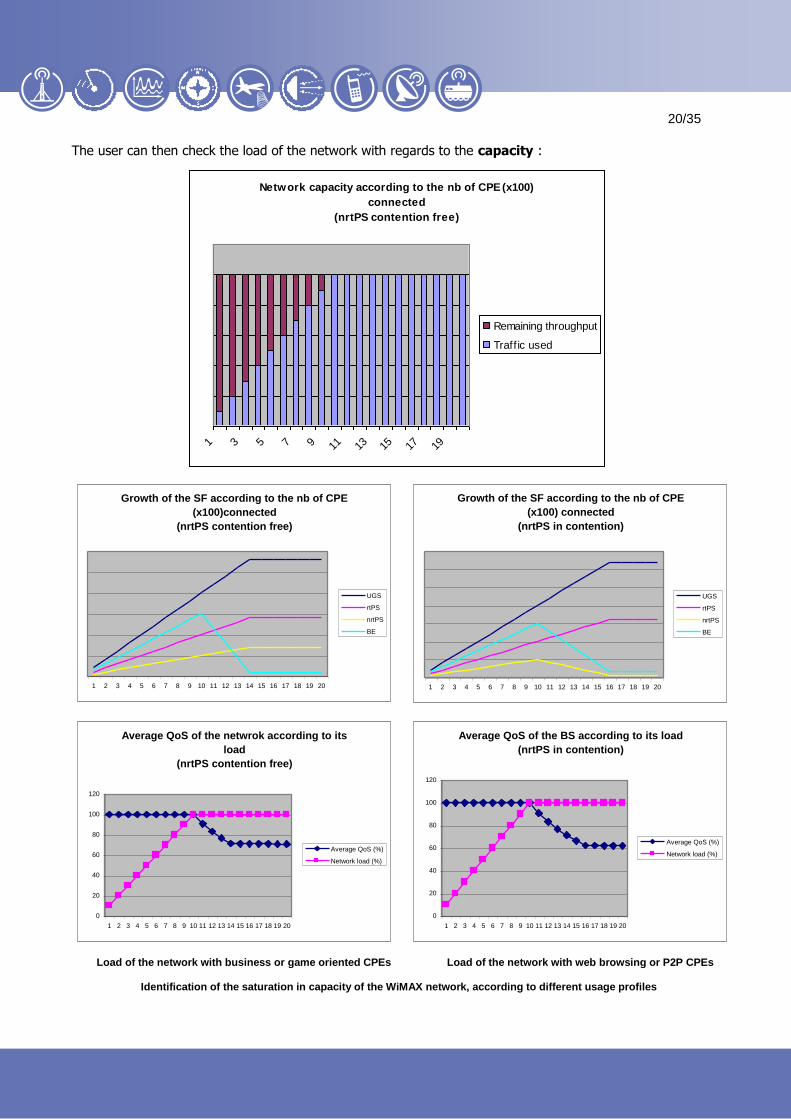
The user can then check the load of the network with regards to the capacity :
Network capacity according to the nb of CPE (x100)
connected
(nrtPS contention free)
1 3 5 7 9 11 13 15 17 19
Remaining throughput
Traffic used
Growth of the SF according to the nb of CPE
(x100)connected
(nrtPS contention free)
1 2 3 4 5 6 7 8 9 10 11 12 13 14 15 16 17 18 19 20
UGS
rtPS
nrtPS
BE
Growth of the SF according to the nb of CPE
(x100) connected
(nrtPS in contention)
1 2 3 4 5 6 7 8 9 10 11 12 13 14 15 16 17 18 19 20
UGS
rtPS
nrtPS
BE
Average QoS of the netwrok according to its
load
(nrtPS contention free)
0
20
40
60
80
100
120
1 2 3 4 5 6 7 8 9 10 11 12 13 14 15 16 17 18 19 20
Average QoS (%)
Network load (%)
Average QoS of the BS according to its load
(nrtPS in contention)
0
20
40
60
80
100
120
1 2 3 4 5 6 7 8 9 10 11 12 13 14 15 16 17 18 19 20
Average QoS (%)
Network load (%)
Load of the network with business or game oriented CPEs Load of the network with web browsing or P2P CPEs
Identification of the saturation in capacity of the WiMAX network, according to different usage profiles
21
21
21/35
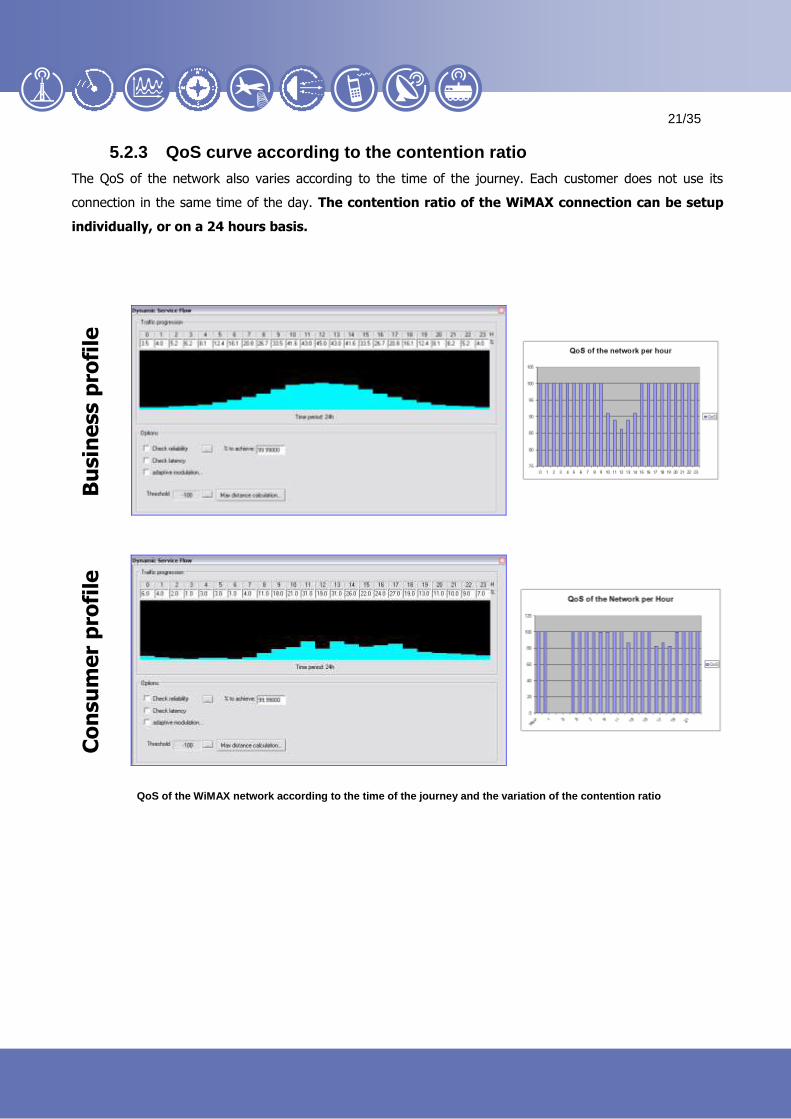
5.2.3 QoS curve according to the contention ratio
The QoS of the network also varies according to the time of the journey. Each customer does not use its
connection in the same time of the day. The contention ratio of the WiMAX connection can be setup
individually, or on a 24 hours basis.
Bu
sin
ess p
rofi
le
Co
nsu
me
r p
rofi
le
QoS of the WiMAX network according to the time of the journey and the variation of the contention ratio

22
22
22/35
6 WiMAX Spectrum analysis
6.1 FWA-type analysis
6.1.1 Coverage mode
Fixed Wireless Access type of networks must be configured in order to lower as much as possible the
interference cases between the sectors of the network. In order to so, the protection ratios according to co-
channel or adjacent channel unwanted signals must be known. The interference generated might decrease the
C/N ratio.
6.1.1.1 Frequency allocation
Based upon the allocated spectrum, the user can ask ICS telecom to automatically find the best frequency
plan that would be used by the BS.
When the connection is made with the highest modulation, the receiver is the most sensible; it therefore
advised to use the worst case scenario when the frequencies are assigned by ICS telecom.
Frequency assignment engine in ICS telecom

23
23
23/35
6.1.1.2 Interference calculation and resulting traffic map
The calculation can be launched on a best RSSI basis, highlighting for each covered location the best non-
interfered sector, or the pink color, meaning that all potential servers interfere one with each other.
Best server map, including interference cases in ICS telecom

24
24
24/35
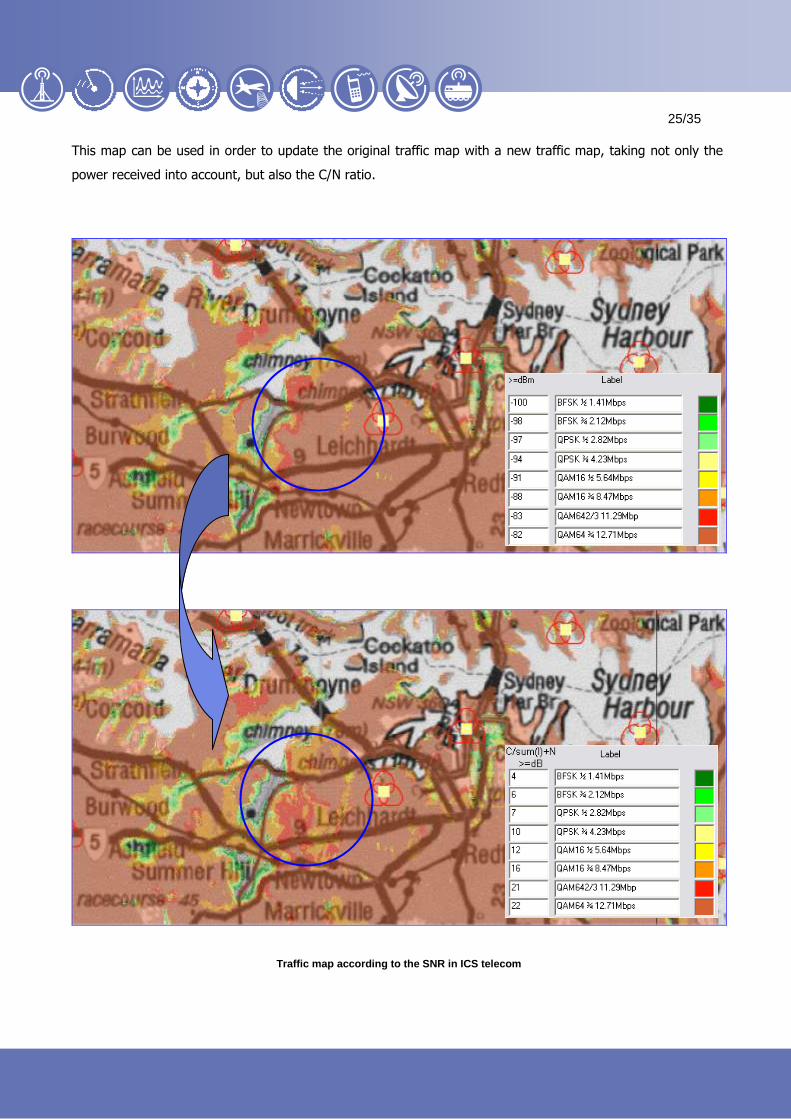
ICS telecom can also display a SNR map, based upon the rejection filter. Here below an example of a SNR
map in C/sum(I) + N mode, using a Noise Floor of –104 dBm, a 1st channel attenuation of 34 dB, and a
second channel attenuation of 50 dB, and an directive Rx pattern with 16 dBi gain.
Signal to Noise ratio map (in C/sum(I)+n mode) of a WiMAX network in ICS telecom
25
25
25/35
This map can be used in order to update the original traffic map with a new traffic map, taking not only the
power received into account, but also the C/N ratio.
Traffic map according to the SNR in ICS telecom

26
26
26/35
6.1.2 PMP interference
6.1.2.1 Power control
To improve the overall performance of the system. The transmitted power
of the CPEs is regulated so that the power received at the base station is at
a predetermined level. ICS telecom adjusts the uplink radiated power at the
CPE side, thereby limiting cases of interference.
6.1.2.2 UL/DL interference
ICS telecom features an interference calculation engine specially dedicated to the Point to Point connections
that allow an easy analysis for uplink and downlink interference cases.
This could be useful for non-synchronized TDD systems, or FDD systems, where the CPEs can raise the noise
floor of the BS they are non-parented to (or the other way).
SDMA systems uplink interference can be managed by specifying the maximum number of terminals that can
be simultaneously connected to a given BS.

27
27
27/35
7 Mobility analysis
ICS telecom features various functions in order to manage the upcoming WiMax mobility.
7.1 Delay spread
Orthogonal Frequency Division Multiplexing (OFDM) is a multiplexing technique that subdivides the
bandwidth into multiple frequency sub-carriers. In an OFDM system, the input data stream is divided into
several parallel sub-streams of reduced data rate (thus increased symbol duration) and each sub-stream is
modulated and transmitted on a separate orthogonal sub-carrier. The increased symbol duration improves the
robustness of OFDM to delay spread. Furthermore, the introduction of the cyclic prefix (CP) can completely
eliminate Inter-Symbol Interference (ISI) as long as the CP duration is longer than the channel delay spread
(source : WiMAX Forum©).
ICS telecom’s OFDM parameters box for simulating multipath reflection can also highlight the cases where the
signal is damaged due to the reflected signal being greater (by a user-defined margin in dB) than the direct
path threshold and with a ToA outside of the OFDM receiver Guard interval:
Constructive and Destructive OFDM signals in ICS telecom
28
28
28/35
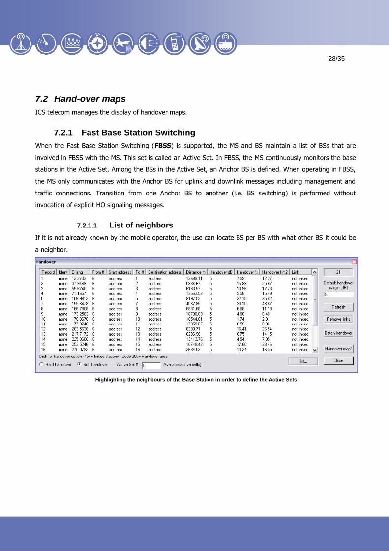
7.2 Hand-over maps
ICS telecom manages the display of handover maps.
7.2.1 Fast Base Station Switching
When the Fast Base Station Switching (FBSS) is supported, the MS and BS maintain a list of BSs that are
involved in FBSS with the MS. This set is called an Active Set. In FBSS, the MS continuously monitors the base
stations in the Active Set. Among the BSs in the Active Set, an Anchor BS is defined. When operating in FBSS,
the MS only communicates with the Anchor BS for uplink and downlink messages including management and
traffic connections. Transition from one Anchor BS to another (i.e. BS switching) is performed without
invocation of explicit HO signaling messages.
7.2.1.1 List of neighbors
If it is not already known by the mobile operator, the use can locate BS per BS with what other BS it could be
a neighbor.
Highlighting the neighbours of the Base Station in order to define the Active Sets
29
29
29/35
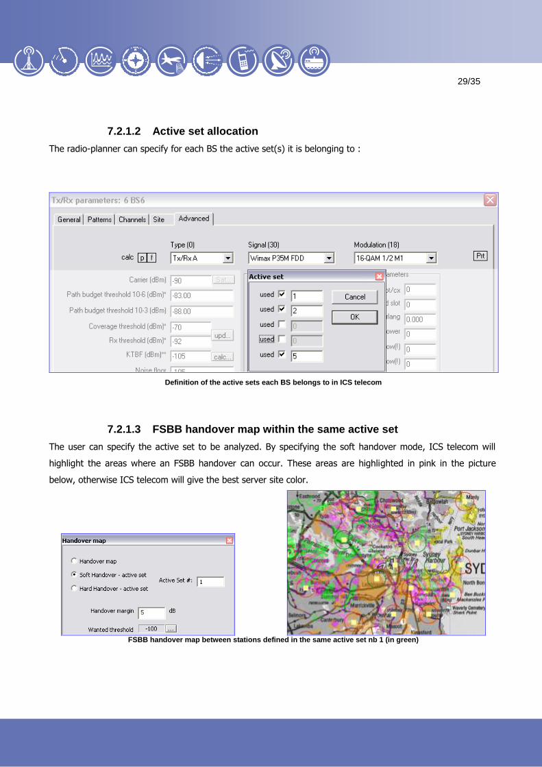
7.2.1.2 Active set allocation
The radio-planner can specify for each BS the active set(s) it is belonging to :
Definition of the active sets each BS belongs to in ICS telecom
7.2.1.3 FSBB handover map within the same active set
The user can specify the active set to be analyzed. By specifying the soft handover mode, ICS telecom will
highlight the areas where an FSBB handover can occur. These areas are highlighted in pink in the picture
below, otherwise ICS telecom will give the best server site color.
FSBB handover map between stations defined in the same active set nb 1 (in green)

30
30
30/35
7.2.2 Hard handover
When the Mobile WiMAX unit will switch from one active set area to another, it performs what is called a hard
handover (HHO). ICS telecom can display where the mobile anchored to a specific active set will have to hard
hand off to another one.
HHO map of a mobile anchored to Active set 1 to any other active set
7.3 Hand-over along a mobile path
If the radio planner is more particularly interested into a mobile path, a dedicated hand over analysis can be
performed, in UL or in DL.
Hand over analysis of a mobile WiMAX unit in ICS telecom

31
31
31/35
8 WiMAX radio-planning : a workflow with ICS telecom
WiMAX radio-planning is an iterative process. A first start would be to select the best locations for the Base
stations (Phase 1), in order to minimize the spectrum required (Phase 2). If the interference areas are too
large, or if the SNR map highlights a high decrease of bandwidth, the network itself might have to be
optimized from Phase 1 again. What's more, guaranteeing coverage without interference does not close the
planning process : the capacity of the designed network needs indeed to be checked, in order to foresee a
potential saturation of the network (Phase 3). If so, the network might have to be densified, generating
therefore additional potential interference (Phase 2). Radio-planning is mean of iteration between these 3
phases, in order to achieve a good balance between them.

32
32
32/35
ATDI Inc. 2, Pidgeon Hill Drive, Suite 560 Sterling - VA 20165 - USA Tel. +1 703 848 4750 Fax +1 703 848 4752 e-mail : [email protected]
http://www.atdi-us.com
ATDI SA 8, rue de l’Arcade 75008 Paris - France Tel. +33 (0) 53 30 89 40 Fax +33 (0)1 53 30 89 49 e-mail : [email protected]
http://www.atdi.com
ATDI Ibérica c/Manuel González Longoria,8 28010 Madrid - Spain Tel. +34 91 44 67 252 Fax +34 91 44 50 383 e-mail : [email protected]
http://www.atdi.es
ATDI Ltd. Kingsland Court - Three Bridges Road Crawley - West Sussex - RH10 1HL - UK Tel. +44 (0)1293 522052 Fax +44 (0)1293 522521 e-mail : [email protected]
http://www.atdi.co.uk
ATDI SAL 812 Tabaris, Avenue Charles Malek Achrafieh, Beirut - Lebanon Tel. +961 1 330 331 Fax +961 1 216 206 e-mail : [email protected]
http://www.atdi.com
ATDI EST Bd. Aviatorilor, 59 Bucharest Romania Tel +40 21 222 42 10 Fax +40 21 222 42 13 e-mail : [email protected]
http://www.atdi.ro
ATDI OOO Sadovnicheskaya st. 72 bld 1 115035 Moscow - Russian Federation Tel. +7 095 252 96 10 Fax +7 501 408 50 74 e-mail : [email protected]
http://www.atdi.ru
ATDI South Pacific PTY Ltd 79 Macarthur Street - Ultimo NSW 2007 - Australia Tel. +61 (0)2 9213 2200 Fax +61 (0)2 9213 2299 e-mail : [email protected]
http://www.atdi.com
ATDI UA partnership with LIS erbitskogo str. 1 02068 Kiev Ukraine Tel +380 44 564 33 68 e-mail : v [email protected]
http:// www.lissoft.com.ua
Software solutions in radiocommunications
Top Related