


Languages
Pages
Legal


ibm.com/redbooks
WebSphere Application Server V7 Messaging Administration Guide
Carla SadtlerLeonard Blunt
Neela M Suram
Messaging with the default messaging provider
Configuration and management
Securing the default messaging provider
Front cover


WebSphere Application Server V7 Messaging Administration Guide
July 2009
International Technical Support Organization
SG24-7770-00

© Copyright International Business Machines Corporation 2009. All rights reserved.Note to U.S. Government Users Restricted Rights -- Use, duplication or disclosure restricted by GSA ADPSchedule Contract with IBM Corp.
First Edition (July 2009)
This edition applies to WebSphere Application Server V7.
Note: Before using this information and the product it supports, read the information in “Notices” on page vii.
Contents
Notices . . . . . . . . . . . . . . . . . . . . . . . . . . . . . . . . . . . . . . . . . . . . . . . . . . . . . . viiTrademarks . . . . . . . . . . . . . . . . . . . . . . . . . . . . . . . . . . . . . . . . . . . . . . . . . . . viii
Preface . . . . . . . . . . . . . . . . . . . . . . . . . . . . . . . . . . . . . . . . . . . . . . . . . . . . . . . ixThe team that wrote this book . . . . . . . . . . . . . . . . . . . . . . . . . . . . . . . . . . . . . . ixBecome a published author . . . . . . . . . . . . . . . . . . . . . . . . . . . . . . . . . . . . . . . . xComments welcome. . . . . . . . . . . . . . . . . . . . . . . . . . . . . . . . . . . . . . . . . . . . . . xi
Chapter 1. WebSphere Application Server asynchronous messaging support. . . . . . . . . . . . . . . . . . . . . . . . . . . . . . . . . . . . . . . . . . . . . . 1
1.1 Messaging . . . . . . . . . . . . . . . . . . . . . . . . . . . . . . . . . . . . . . . . . . . . . . . . . . 21.2 Runtime messaging resources . . . . . . . . . . . . . . . . . . . . . . . . . . . . . . . . . . 31.3 Configuring JMS providers . . . . . . . . . . . . . . . . . . . . . . . . . . . . . . . . . . . . . 6
1.3.1 JMS provider configuration for the default messaging provider . . . . . 71.3.2 JMS provider configuration for the WebSphere MQ provider . . . . . . . 81.3.3 JMS provider configuration for a generic JMS provider . . . . . . . . . . 10
1.4 Configuring WebSphere JMS administered objects . . . . . . . . . . . . . . . . . 121.4.1 JMS connection factories and destinations. . . . . . . . . . . . . . . . . . . . 121.4.2 Message-driven beans and activation specifications . . . . . . . . . . . . 131.4.3 Common configuration properties . . . . . . . . . . . . . . . . . . . . . . . . . . . 13
1.5 Configuring the default messaging provider . . . . . . . . . . . . . . . . . . . . . . . 141.5.1 Configuring a connection factory. . . . . . . . . . . . . . . . . . . . . . . . . . . . 141.5.2 Configuring JMS destinations . . . . . . . . . . . . . . . . . . . . . . . . . . . . . . 231.5.3 Configuring JMS activation specifications. . . . . . . . . . . . . . . . . . . . . 33
1.6 Configuring the WebSphere MQ provider . . . . . . . . . . . . . . . . . . . . . . . . . 391.6.1 Support for CCDT . . . . . . . . . . . . . . . . . . . . . . . . . . . . . . . . . . . . . . . 401.6.2 Configuring a connection factory. . . . . . . . . . . . . . . . . . . . . . . . . . . . 401.6.3 WebSphere MQ destination . . . . . . . . . . . . . . . . . . . . . . . . . . . . . . . 471.6.4 Configuring activation specifications . . . . . . . . . . . . . . . . . . . . . . . . . 521.6.5 Thread pool for WebSphere MQ JMS provider . . . . . . . . . . . . . . . . . 55
1.7 Configuring a generic JMS provider . . . . . . . . . . . . . . . . . . . . . . . . . . . . . 561.7.1 JMS connection factory configuration . . . . . . . . . . . . . . . . . . . . . . . . 561.7.2 JMS destination configuration . . . . . . . . . . . . . . . . . . . . . . . . . . . . . . 59
1.8 Thin Client for JMS . . . . . . . . . . . . . . . . . . . . . . . . . . . . . . . . . . . . . . . . . . 601.9 References and resources . . . . . . . . . . . . . . . . . . . . . . . . . . . . . . . . . . . . 62
Chapter 2. Default messaging provider concepts . . . . . . . . . . . . . . . . . . . 652.1 Concepts and architecture . . . . . . . . . . . . . . . . . . . . . . . . . . . . . . . . . . . . 66
2.1.1 Service integration bus . . . . . . . . . . . . . . . . . . . . . . . . . . . . . . . . . . . 66
© Copyright IBM Corp. 2009. All rights reserved. iii

2.1.2 Bus member . . . . . . . . . . . . . . . . . . . . . . . . . . . . . . . . . . . . . . . . . . . 672.1.3 Messaging engines . . . . . . . . . . . . . . . . . . . . . . . . . . . . . . . . . . . . . . 672.1.4 Message stores. . . . . . . . . . . . . . . . . . . . . . . . . . . . . . . . . . . . . . . . . 732.1.5 Destinations . . . . . . . . . . . . . . . . . . . . . . . . . . . . . . . . . . . . . . . . . . . 752.1.6 Foreign bus connections . . . . . . . . . . . . . . . . . . . . . . . . . . . . . . . . . . 802.1.7 JMS and the default messaging provider . . . . . . . . . . . . . . . . . . . . . 87
2.2 Runtime components . . . . . . . . . . . . . . . . . . . . . . . . . . . . . . . . . . . . . . . . 882.2.1 SIB service . . . . . . . . . . . . . . . . . . . . . . . . . . . . . . . . . . . . . . . . . . . . 882.2.2 Service integration bus transport chains . . . . . . . . . . . . . . . . . . . . . . 892.2.3 Message stores. . . . . . . . . . . . . . . . . . . . . . . . . . . . . . . . . . . . . . . . . 952.2.4 Exception destinations . . . . . . . . . . . . . . . . . . . . . . . . . . . . . . . . . . 1052.2.5 Service integration bus links . . . . . . . . . . . . . . . . . . . . . . . . . . . . . . 1072.2.6 WebSphere MQ links . . . . . . . . . . . . . . . . . . . . . . . . . . . . . . . . . . . 1102.2.7 WebSphere MQ servers . . . . . . . . . . . . . . . . . . . . . . . . . . . . . . . . . 120
2.3 Service integration bus topologies . . . . . . . . . . . . . . . . . . . . . . . . . . . . . 1222.3.1 One bus, one bus member (single server) . . . . . . . . . . . . . . . . . . . 1232.3.2 One bus, one bus member (a cluster). . . . . . . . . . . . . . . . . . . . . . . 1242.3.3 One bus, multiple bus members . . . . . . . . . . . . . . . . . . . . . . . . . . . 1272.3.4 Multiple buses . . . . . . . . . . . . . . . . . . . . . . . . . . . . . . . . . . . . . . . . . 1272.3.5 WebSphere MQ Server. . . . . . . . . . . . . . . . . . . . . . . . . . . . . . . . . . 129
2.4 High availability and workload management . . . . . . . . . . . . . . . . . . . . . . 1302.4.1 Cluster bus members for high availability . . . . . . . . . . . . . . . . . . . . 1302.4.2 Cluster bus members for workload management . . . . . . . . . . . . . . 1312.4.3 Partitioned queues . . . . . . . . . . . . . . . . . . . . . . . . . . . . . . . . . . . . . 1312.4.4 JMS clients connecting to a cluster of messaging engines. . . . . . . 1322.4.5 Preferred servers and core group policies . . . . . . . . . . . . . . . . . . . 1332.4.6 Best practices . . . . . . . . . . . . . . . . . . . . . . . . . . . . . . . . . . . . . . . . . 136
2.5 Service integration bus and message-driven beans . . . . . . . . . . . . . . . . 1362.5.1 Message-driven beans connecting to the bus. . . . . . . . . . . . . . . . . 1362.5.2 MDBs and clusters . . . . . . . . . . . . . . . . . . . . . . . . . . . . . . . . . . . . . 139
2.6 Connecting to a service integration bus . . . . . . . . . . . . . . . . . . . . . . . . . 1402.6.1 JMS client run time environment. . . . . . . . . . . . . . . . . . . . . . . . . . . 1402.6.2 Controlling messaging engine selection . . . . . . . . . . . . . . . . . . . . . 144
Chapter 3. Default messaging provider configuration and management1553.1 Configuration and management overview. . . . . . . . . . . . . . . . . . . . . . . . 1563.2 SIB service . . . . . . . . . . . . . . . . . . . . . . . . . . . . . . . . . . . . . . . . . . . . . . . 1563.3 Creating a bus . . . . . . . . . . . . . . . . . . . . . . . . . . . . . . . . . . . . . . . . . . . . . 1583.4 Adding bus members . . . . . . . . . . . . . . . . . . . . . . . . . . . . . . . . . . . . . . . 161
3.4.1 Adding a single server as a bus member . . . . . . . . . . . . . . . . . . . . 1623.4.2 Adding a server to a bus using the default data store. . . . . . . . . . . 1663.4.3 Adding a bus member with a non-default data store. . . . . . . . . . . . 1673.4.4 Adding a cluster as a bus member . . . . . . . . . . . . . . . . . . . . . . . . . 171
iv WebSphere Application Server V7 Messaging Administration Guide

3.4.5 Modifying the messaging engine policy . . . . . . . . . . . . . . . . . . . . . 1763.4.6 Manually creating messaging engine policies. . . . . . . . . . . . . . . . . 177
3.5 Creating and using a WebSphere MQ Server. . . . . . . . . . . . . . . . . . . . . 1823.5.1 Creating a WebSphere MQ Server . . . . . . . . . . . . . . . . . . . . . . . . . 1833.5.2 Adding the WebSphere MQ server as a bus member . . . . . . . . . . 185
3.6 Creating destinations. . . . . . . . . . . . . . . . . . . . . . . . . . . . . . . . . . . . . . . . 1863.6.1 Creating a queue destination . . . . . . . . . . . . . . . . . . . . . . . . . . . . . 1863.6.2 Creating a topic space destination . . . . . . . . . . . . . . . . . . . . . . . . . 1893.6.3 Creating an alias destination. . . . . . . . . . . . . . . . . . . . . . . . . . . . . . 189
3.7 Adding messaging engines to a cluster. . . . . . . . . . . . . . . . . . . . . . . . . . 1913.8 Working with foreign buses . . . . . . . . . . . . . . . . . . . . . . . . . . . . . . . . . . . 192
3.8.1 Setting up a foreign bus connection to a service integration bus . . 1923.8.2 Setting up a foreign bus connection to an MQ queue manager . . . 1933.8.3 Routing messages from a local bus to a remote bus . . . . . . . . . . . 197
3.9 Problem determination . . . . . . . . . . . . . . . . . . . . . . . . . . . . . . . . . . . . . . 1983.9.1 Normal startup messages . . . . . . . . . . . . . . . . . . . . . . . . . . . . . . . . 1993.9.2 CWSIS1535E: Messaging engine’s unique ID does not match . . . 2003.9.3 CWSIT0019E: No suitable messaging engine . . . . . . . . . . . . . . . . 201
Chapter 4. Securing the service integration bus . . . . . . . . . . . . . . . . . . . 2034.1 Overview . . . . . . . . . . . . . . . . . . . . . . . . . . . . . . . . . . . . . . . . . . . . . . . . . 2044.2 Understanding the example environment . . . . . . . . . . . . . . . . . . . . . . . . 2064.3 Creating a secure bus . . . . . . . . . . . . . . . . . . . . . . . . . . . . . . . . . . . . . . . 209
4.3.1 Creating a secure bus using the administrative console. . . . . . . . . 2104.3.2 Creating a secure bus using wsadmin . . . . . . . . . . . . . . . . . . . . . . 2194.3.3 Understanding the secure bus defaults. . . . . . . . . . . . . . . . . . . . . . 220
4.4 Securing the data store . . . . . . . . . . . . . . . . . . . . . . . . . . . . . . . . . . . . . . 2294.5 Connecting to a secure bus. . . . . . . . . . . . . . . . . . . . . . . . . . . . . . . . . . . 234
4.5.1 Configuring the connector role using administrative console . . . . . 2344.5.2 Configure the connector role using wsadmin . . . . . . . . . . . . . . . . . 237
4.6 Configuring authorization on queue destinations . . . . . . . . . . . . . . . . . . 2374.6.1 Configuring authorization using the administrative console . . . . . . 2384.6.2 Configuring authorization using wsadmin . . . . . . . . . . . . . . . . . . . . 242
4.7 Configuring authorization on temp destinations . . . . . . . . . . . . . . . . . . . 2434.7.1 Configuring authorization using the administrative console . . . . . . 2454.7.2 Configuring authorization using wsadmin . . . . . . . . . . . . . . . . . . . . 248
4.8 Configuring authorization on topics . . . . . . . . . . . . . . . . . . . . . . . . . . . . . 2504.8.1 Configuring authorization using the administrative console . . . . . . 2514.8.2 Configuring authorization using wsadmin . . . . . . . . . . . . . . . . . . . . 264
4.9 Configure application resources . . . . . . . . . . . . . . . . . . . . . . . . . . . . . . . 2654.9.1 Configure activation specifications . . . . . . . . . . . . . . . . . . . . . . . . . 2674.9.2 Configuring security on connection factories . . . . . . . . . . . . . . . . . 2724.9.3 Configuring application resources during application install . . . . . . 275
Contents v

4.10 Configuring foreign bus connections . . . . . . . . . . . . . . . . . . . . . . . . . . . 2824.10.1 Configuration using the administrative console. . . . . . . . . . . . . . . 2844.10.2 Configuring using wsadmin . . . . . . . . . . . . . . . . . . . . . . . . . . . . . . 298
4.11 Other considerations . . . . . . . . . . . . . . . . . . . . . . . . . . . . . . . . . . . . . . . 2994.12 AdminTask wsadmin commands for security . . . . . . . . . . . . . . . . . . . . 301
Related publications . . . . . . . . . . . . . . . . . . . . . . . . . . . . . . . . . . . . . . . . . . 307IBM Redbooks publications . . . . . . . . . . . . . . . . . . . . . . . . . . . . . . . . . . . . . . 307Other publications . . . . . . . . . . . . . . . . . . . . . . . . . . . . . . . . . . . . . . . . . . . . . 307Online resources . . . . . . . . . . . . . . . . . . . . . . . . . . . . . . . . . . . . . . . . . . . . . . 308How to get Redbooks . . . . . . . . . . . . . . . . . . . . . . . . . . . . . . . . . . . . . . . . . . . 308Help from IBM . . . . . . . . . . . . . . . . . . . . . . . . . . . . . . . . . . . . . . . . . . . . . . . . 308
vi WebSphere Application Server V7 Messaging Administration Guide

Notices
This information was developed for products and services offered in the U.S.A.
IBM may not offer the products, services, or features discussed in this document in other countries. Consult your local IBM representative for information about the products and services currently available in your area. Any reference to an IBM product, program, or service is not intended to state or imply that only that IBM product, program, or service may be used. Any functionally equivalent product, program, or service that does not infringe any IBM intellectual property right may be used instead. However, it is the user's responsibility to evaluate and verify the operation of any non-IBM product, program, or service.
IBM may have patents or pending patent applications covering subject matter described in this document. The furnishing of this document does not give you any license to these patents. You can send license inquiries, in writing, to: IBM Director of Licensing, IBM Corporation, North Castle Drive, Armonk, NY 10504-1785 U.S.A.
The following paragraph does not apply to the United Kingdom or any other country where such provisions are inconsistent with local law: INTERNATIONAL BUSINESS MACHINES CORPORATION PROVIDES THIS PUBLICATION "AS IS" WITHOUT WARRANTY OF ANY KIND, EITHER EXPRESS OR IMPLIED, INCLUDING, BUT NOT LIMITED TO, THE IMPLIED WARRANTIES OF NON-INFRINGEMENT, MERCHANTABILITY OR FITNESS FOR A PARTICULAR PURPOSE. Some states do not allow disclaimer of express or implied warranties in certain transactions, therefore, this statement may not apply to you.
This information could include technical inaccuracies or typographical errors. Changes are periodically made to the information herein; these changes will be incorporated in new editions of the publication. IBM may make improvements and/or changes in the product(s) and/or the program(s) described in this publication at any time without notice.
Any references in this information to non-IBM Web sites are provided for convenience only and do not in any manner serve as an endorsement of those Web sites. The materials at those Web sites are not part of the materials for this IBM product and use of those Web sites is at your own risk.
IBM may use or distribute any of the information you supply in any way it believes appropriate without incurring any obligation to you.
Information concerning non-IBM products was obtained from the suppliers of those products, their published announcements or other publicly available sources. IBM has not tested those products and cannot confirm the accuracy of performance, compatibility or any other claims related to non-IBM products. Questions on the capabilities of non-IBM products should be addressed to the suppliers of those products.
This information contains examples of data and reports used in daily business operations. To illustrate them as completely as possible, the examples include the names of individuals, companies, brands, and products. All of these names are fictitious and any similarity to the names and addresses used by an actual business enterprise is entirely coincidental.
COPYRIGHT LICENSE:
This information contains sample application programs in source language, which illustrate programming techniques on various operating platforms. You may copy, modify, and distribute these sample programs in any form without payment to IBM, for the purposes of developing, using, marketing or distributing application programs conforming to the application programming interface for the operating platform for which the sample programs are written. These examples have not been thoroughly tested under all conditions. IBM, therefore, cannot guarantee or imply reliability, serviceability, or function of these programs.
© Copyright IBM Corp. 2009. All rights reserved. vii

Trademarks
IBM, the IBM logo, and ibm.com are trademarks or registered trademarks of International Business Machines Corporation in the United States, other countries, or both. These and other IBM trademarked terms are marked on their first occurrence in this information with the appropriate symbol (® or ™), indicating US registered or common law trademarks owned by IBM at the time this information was published. Such trademarks may also be registered or common law trademarks in other countries. A current list of IBM trademarks is available on the Web at http://www.ibm.com/legal/copytrade.shtml
The following terms are trademarks of the International Business Machines Corporation in the United States, other countries, or both:
DB2®developerWorks®IBM®
Lotus®Parallel Sysplex®Redbooks®
Redbooks (logo) ®WebSphere®z/OS®
The following terms are trademarks of other companies:
EJB, J2EE, J2SE, Java, JDBC, JDK, JNI, JRE, JVM, and all Java-based trademarks are trademarks of Sun Microsystems, Inc. in the United States, other countries, or both.
Windows Server, Windows, and the Windows logo are trademarks of Microsoft Corporation in the United States, other countries, or both.
Other company, product, or service names may be trademarks or service marks of others.
viii WebSphere Application Server V7 Messaging Administration Guide

Preface
WebSphere® Application Server V7 supports asynchronous messaging based on the Java™ Message Service (JMS) and the Java EE Connector Architecture (JCA) specifications. Asynchronous messaging support provides applications with the ability to create, send, receive, and read asynchronous requests as messages. WebSphere Application Server provides a default messaging provider, as well as support for WebSphere MQ and generic messaging providers.
This IBM® Redbooks® publication provides information about the messaging features of WebSphere Application Server V7. It contains information about configuring, securing, and managing messaging resources, with a focus on the WebSphere default messaging provider.
The team that wrote this book
This book was produced by a team of specialists from around the world working at the International Technical Support Organization, Raleigh Center.
Carla Sadtler is a Consulting IT Specialist at the ITSO, Raleigh Center. She writes extensively about WebSphere products and solutions. Before joining the ITSO in 1985, Carla worked in the Raleigh branch office as a Program Support Representative, supporting MVS customers. She holds a degree in Mathematics from the University of North Carolina at Greensboro.
Leonard Blunt is a Senior IT Specialist working in ASEAN Software Lab Services, based in Singapore. Leonard has a history in middleware architecture design and development, with an emphasis on multi-channel e-business applications and previous integrations. Leonard's origins are in building application middleware architectures, with a focus on rapid application
development through product integration and the generation of code. Leonard is experienced in implementing J2EE/Java and service-oriented architecture (SOA) solutions and is passionate about producing robust, hardened software that incorporates from its inception performance, monitoring, and security. Leonard has been working with WebSphere Application Server since 2003, and graduated from Wollongong University in New South Wales Australia with a Bachelor of Engineering (Computer) in 1999.
© Copyright IBM Corp. 2009. All rights reserved. ix

Neela M Suram is an IT Specialist at IBM India Software Labs, Bangalore. He is currently working as a WebSphere Consultant with IBM Business Partner Technical Strategy and Enablement (BPTSE) Developer Services team, enabling and supporting worldwide business partners for WebSphere products. He has experience in design, development, and porting of applications
from distributed platforms to the z platform. Since he joined IBM in 2001, he has held various roles, from design and development of applications to working with earlier systems running on z platform. He holds a master’s degree in Software Systems from BITS Pilani, India.
Thanks to the following people for their contributions to this project:
Margaret TicknorInternational Technical Support Organization, Raleigh Center
Alasdair Nottingham Matthew LemingAndrew LeonardRichard Ellis Mayur Raja Alasdair Nottingham David WarePaul HarrisGareth BottomleyIBM UK
Thanks to the authors of the messaging chapters in WebSphere Application Server V6 System Management & Configuration Handbook, SG24-6451, published in March 2005:
Martin Smithson and Martin Phillips
Become a published author
Join us for a two- to six-week residency program! Help write a book dealing with specific products or solutions, while getting hands-on experience with leading-edge technologies. You will have the opportunity to team with IBM technical professionals, Business Partners, and Clients.
Your efforts will help increase product acceptance and customer satisfaction. As a bonus, you will develop a network of contacts in IBM development labs, and increase your productivity and marketability.
x WebSphere Application Server V7 Messaging Administration Guide

Find out more about the residency program, browse the residency index, and apply online at:
ibm.com/redbooks/residencies.html
Comments welcome
Your comments are important to us!
We want our books to be as helpful as possible. Send us your comments about this book or other IBM Redbooks publications in one of the following ways:
� Use the online Contact us review Redbooks form found at:
ibm.com/redbooks
� Send your comments in an e-mail to:
� Mail your comments to:
IBM Corporation, International Technical Support OrganizationDept. HYTD Mail Station P0992455 South RoadPoughkeepsie, NY 12601-5400
Preface xi

xii WebSphere Application Server V7 Messaging Administration Guide

Chapter 1. WebSphere Application Server asynchronous messaging support
In this chapter we describe the concepts behind the asynchronous messaging functionality provided as part of WebSphere Application Server. We discuss:
� “Messaging” on page 2� “Configuring JMS providers” on page 6� “Configuring WebSphere JMS administered objects” on page 12� “Configuring the default messaging provider” on page 14� “Configuring the WebSphere MQ provider” on page 39� “Configuring a generic JMS provider” on page 56� “Thin Client for JMS” on page 60� “References and resources” on page 62
1
© Copyright IBM Corp. 2009. All rights reserved. 1

1.1 MessagingThe term messaging, in the generic sense, is usually used to describe the exchange of information between two interested parties. In the context of computer science, messaging can be used to loosely describe a broad range of mechanisms used to communicate data. For example, e-mail and instant messaging are two communication mechanisms that could be described using the term messaging. In both cases, information is exchanged between two parties, but the technology used to achieve the exchange is different.
There are two messaging types that define the mode of interaction between the sending and receiving applications:
� Synchronous messaging
Synchronous messaging involves tightly coupled processes, where the sending and receiving applications communicate directly and both must be available in order for the message exchange to occur.
� Asynchronous messaging
Asynchronous messaging involves loosely coupled processes, where the sending and receiving applications communicate through a messaging provider. The sending application is able to pass the data to the messaging provider and then continue with its processing. The receiving application is able to connect to the messaging provider, possibly at some later point in time, to retrieve the data.
For detailed information about the concepts of messaging, see Enterprise Messaging Using JMS and WebSphere (references are listed in 1.9, “References and resources” on page 62).
This book focuses on asynchronous messaging in WebSphere. WebSphere Application Server supports asynchronous messaging through the use of the Java Message Service (JMS). The JMS API is the standard Java API for accessing enterprise messaging systems from Java programs. In other words, it is a standard API that sending and receiving applications written in Java can use to access a messaging provider to create, send, receive, and read messages.
The JMS API was first included in Version 1.2 of the Java EE specification. This specification required that the JMS API definitions be included in a Java EE product, but that the platform was not required to include an implementation of the JMS ConnectionFactory and Destination objects. Subsequent versions of the Java EE specification have placed further requirements on application server vendors. WebSphere Application Server V7 is fully compliant with the Java EE 5 specification. These requirements are documented in section 6.6, “Java
2 WebSphere Application Server V7 Messaging Administration Guide

Message Service (JMS) 1.1 Requirements,” of the Java EE 5 Specification. The Java EE 5 Specification can be downloaded from the following Web site:
http://jcp.org/en/jsr/detail?id=244
1.2 Runtime messaging resources
Messaging applications require runtime resources in order to deliver messages. These resources consist of the messaging provider implementation that holds the messages on queue and topic destinations for delivery and the JMS configuration objects that the application uses to access the queue and topic destinations.
WebSphere Application Server provides a default messaging provider that uses the service integration bus as the messaging system. In addition, WebSphere supports WebSphere MQ as a messaging provider and third-party messaging providers that implement the ASF component of the JMS 1.0.2 specification. WebSphere supports JCA 1.5 compliant messaging providers through the installation of resource adapters that allow applications to connect to third-party provided external providers.
Chapter 1. WebSphere Application Server asynchronous messaging support 3

Figure 1-1 illustrates the runtime resources that are configured for a messaging application. While all three messaging providers can be configured in the system, an application would only make use of one provider. In Figure 1-1, the resources for the default messaging provider have been configured for the application.
Figure 1-1 JMS provider components
The JMS configuration objects used by the application to connect to a provider and to access queues and topics on the provider are specific to the JMS provider. This chapter focuses on the JMS configuration objects and shows how they can be configured for each provider type.
Application ServerMessaging Providers
Default Messaging Provider
Service Integration Bus
Queue Topic
Outbound Messages
JMS Provider
Connection Factory
JMS Queue / Topic
Application
Inbound Messages
Activation Spec
MDB
Generic JMS Provider
WebSphere MQ
Queue Topic
Queue Manager
TopicQueue
4 WebSphere Application Server V7 Messaging Administration Guide

JMS configuration objectsIn order for a JMS provider to be used by a messaging application, the following items must be configured using the WebSphere administrative tools:
� A JMS provider
A JMS provider is configured in WebSphere to manage resources specific to a messaging provider implementation. The JMS administered objects required to connect to the provider and the destinations (queues or topics) on the provider are associated with the JMS provider definition.
JMS provider definitions come preconfigured in WebSphere for the default messaging provider, the WebSphere MQ provider, and the V5 default messaging provider. You only need to create a new JMS provider if you plan to use a third-party messaging provider.
� A JMS connection factory
The connection factory is used by an application to connect to the JMS provider. The connection factory configuration includes the JNDI name that binds it to the WebSphere name space and the information required to connect to the JMS provider.
For example, a connection factory for a WebSphere MQ provider would include the queue manager name and the information required to connect to that queue manager. A connection factory for the default messaging provider would include the bus name.
� JMS queues and JMS topics
These resources define the destination for messages sent to the provider. Applications attach to these resources as producers, consumers, or both to exchange messages. Queue destinations are used for point-to-point messaging, while topic destinations are used for publish/subscribe messaging.
The corresponding destinations on the provider must be created through administrative facilities provided by the implementation. For example, the corresponding queues and topics must be defined to WebSphere MQ using the WebSphere MQ Explorer. Queues and topics for the default messaging provider can be configured on the service integration bus using the WebSphere administrative tools.
Chapter 1. WebSphere Application Server asynchronous messaging support 5

� Activation specifications
An activation specification is created and associated with a message-driven bean in order for the beans to receive messages. Note that if you are using third-party JMS providers that implement ASF, you would need to configure a message listener port instead an activation spec.
� The underlying queues and topics on the messaging systems
The JMS destinations are representations of a real endpoint provided by the JMS provider implementation. This chapter focuses on the JMS configuration objects. Chapter 3, “Default messaging provider configuration and management” on page 155, shows how the destinations are created on the service integration bus for the WebSphere default JMS messaging provider.
1.3 Configuring JMS providers
WebSphere Application Server V7 supports the following JMS providers:
� The WebSphere Application Server default messaging provider, which is a JCA resource adapter implementation that is fully integrated in WebSphere
The default messaging provider uses a service integration bus as the messaging system.
Terminology: A service integration bus (or just bus) consists of a group of one or more application servers or server clusters in a WebSphere Application Server cell that cooperate to provide asynchronous messaging.
A messaging engine is a server component that provides the core messaging function of a service integration bus. A messaging engine manages bus resources and allows applications to communicate with the bus.
� The WebSphere MQ messaging provider, which uses a WebSphere MQ installation as the provider
The WebSphere administration tools can be used to both configure and manage WebSphere MQ JMS administered objects. The creation and management of the corresponding queue managers, channels, and queues must be performed using WebSphere MQ native tools.
� Third-party messaging providers that implement either a JCA Version 1.5 resource adapter or the Application Server Facilities (ASF) component of the JMS Version 1.0.2 specification
� V5 default messaging provider, which is supported for migration purposes
This provider is not discussed in this book. For information about the V5 default messaging provider, see IBM WebSphere Application Server V5.1
6 WebSphere Application Server V7 Messaging Administration Guide

System Management and Configuration WebSphere Handbook Series, SG24-6195.
The sections that follow describe how the WebSphere administrative console can be used to manage the JMS provider definitions.
1.3.1 JMS provider configuration for the default messaging provider
The default messaging provider is fully compliant with Version 1.1 of the JMS specification and supports both point-to-point and publish/subscribe messaging.
A JMS provider for the default messaging provider has been preconfigured in WebSphere Application Server at every scope. To view the properties of the default messaging provider, use the administrative console to complete the following steps:
1. In the navigation tree, expand Resources → JMS → JMS Providers. This opens a list of JMS providers. A default messaging provider is preconfigured for you at each scope. You can narrow down the list by setting the scope.
2. Click Default messaging provider to open the configuration page.
New in V7: New administrative console panels have been added for the default messaging provider to:
� View all the references to messaging resources present in the deployment descriptor of an application.
� View all the applications and messaging resources that reference the selected destination, both directly and indirectly.
Note: You do not have to configure the underlying bus resources before configuring the corresponding JMS resources. However, certain fields within the default messaging provider administration panels are populated with relevant bus resources, if they exist. Therefore, to simplify the process of creating JMS resources for the default messaging provider, we recommend that you create and configure the underlying service integration bus resources first.
Chapter 1. WebSphere Application Server asynchronous messaging support 7

The JMS provider definition does not have any configurable properties exposed in the console, but the important thing is that the JMS administered objects associated with this provider can be configured from the links in the Additional properties section (Figure 1-2).
Figure 1-2 Default messaging provider configuration properties
The default messaging provider is implemented as a JCA resource adapter. You can view the properties of the resource adapter from the administrative console, however, we do not expect you to need to change anything in this configuration. The resource adapter can be found by doing the following:
1. In the navigation tree, expand Resources → Resource Adapters → Resource adapters.
2. In the Preferences section, check the box by Show built-in resources and click Apply.
3. The resource adapter is called the SIB JMS Resource Adapter. The adapter is configured at every scope.
1.3.2 JMS provider configuration for the WebSphere MQ providerWebSphere Application Server V7 supplies a pre-installed resource adapter for communicating with installations of the following products:
� WebSphere MQ� WebSphere Event Broker� WebSphere Message Broker
8 WebSphere Application Server V7 Messaging Administration Guide
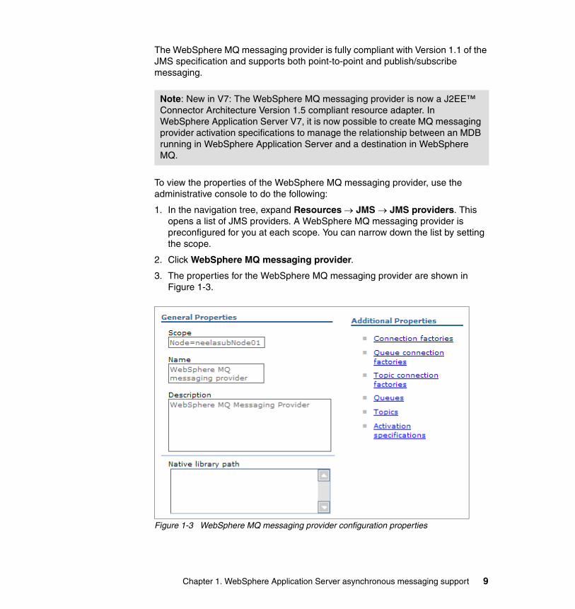
The WebSphere MQ messaging provider is fully compliant with Version 1.1 of the JMS specification and supports both point-to-point and publish/subscribe messaging.
To view the properties of the WebSphere MQ messaging provider, use the administrative console to do the following:
1. In the navigation tree, expand Resources → JMS → JMS providers. This opens a list of JMS providers. A WebSphere MQ messaging provider is preconfigured for you at each scope. You can narrow down the list by setting the scope.
2. Click WebSphere MQ messaging provider.
3. The properties for the WebSphere MQ messaging provider are shown in Figure 1-3.
Figure 1-3 WebSphere MQ messaging provider configuration properties
Note: New in V7: The WebSphere MQ messaging provider is now a J2EE™ Connector Architecture Version 1.5 compliant resource adapter. In WebSphere Application Server V7, it is now possible to create MQ messaging provider activation specifications to manage the relationship between an MDB running in WebSphere Application Server and a destination in WebSphere MQ.
Chapter 1. WebSphere Application Server asynchronous messaging support 9

1.3.3 JMS provider configuration for a generic JMS providerWebSphere Application Server supports the use of third-party JMS providers within its runtime environment through the use of a generic JMS provider. A generic JMS provider must be defined to WebSphere Application Server before any JMS resources can be configured for that provider. Defining a generic JMS provider to WebSphere ensures that the JMS provider classes are available on the application server classpath at run time.
We recommend a generic JMS provider in the following situations:
� A third-party messaging system already exists in the environment, and into which the WebSphere installation is required to integrate directly.
� A third-party JMS provider supports functionality that is not available using the default messaging or WebSphere MQ messaging providers, and that would be useful for the user’s messaging environment.
WebSphere interaction with a generic JMS providerThe JMS administered objects for a generic JMS provider are bound into the local JNDI name space within WebSphere Application Server. These JNDI entries act as aliases to the real JMS administered objects that have been configured in the external JNDI name space of the messaging provider. This relationship is shown in Figure 1-4.
Figure 1-4 Generic JMS provider components
Note: WebSphere Application Server also supports the use of third-party JMS providers that are implemented as JCA resource adapters. The JMS resources for such JMS providers are configured using the resource adapter configuration panels.
Application Server
Local JNDIMessaging Provider
Admin Tool
Application
ConnectionFactory
Destination
Generic JMS Provider
External JNDI
ConnectionFactory
Destination
Destination
10 WebSphere Application Server V7 Messaging Administration Guide

This indirection is achieved by providing additional JNDI information when configuring the JMS administered objects for the generic JMS provider. JMS client application code is not affected in any way. It is the responsibility of the WebSphere runtime to resolve accesses to the real JNDI entries in the external name space.
WebSphere is not responsible for binding the JMS administered objects into the external name space. This administrative task, along with creating the underlying messaging objects, queues, and topics, must be performed using the tools provided by the generic JMS provider.
Defining a generic JMS providerBefore you can configure a generic JMS provider, you must install the underlying messaging provider software and configure it using the tools and information provided with the messaging provider.
To define a new generic messaging provider, use the administrative console to complete the following steps:
1. In the navigation tree, expand Resources → JMS → JMS providers and set the scope.
2. Click New in the content pane.
3. Define the JMS provider by specifying the appropriate values in the General Properties section of the content pane:
– Name: The name by which the generic JMS provider is known for administrative purposes.
– Class path: The list of paths or JAR file names that together form the location for the generic JMS provider’s classes.
– Native library path: An optional path to any native libraries (.dll’s, .so’s) required by the generic JMS provider.
– External initial context factory: This property is the Java classname of the generic JMS providers initial context factory. For example, this would be the com.swiftmq.jndi.InitialContextFactoryImpl for the SwiftMQ JMS provider.
– External provider URL: This is the JMS provider URL for external JNDI lookups. The external provider URL specifies how the initial context factory should connect to the external naming service. The format of the external provider URL is:
<protocol>://<host name>:<port number>.
Chapter 1. WebSphere Application Server asynchronous messaging support 11

Continuing with the example, the provider URL smqp://localhost:4001 indicates that the initial context factory connects to the SwiftMQ naming service using port 4001 on the local machine and using the sqmq protocol.
Click OK.
4. Save the changes and synchronize them with the nodes.
Once the generic JMS provider has been defined, JMS administered objects can be configured for it.
1.4 Configuring WebSphere JMS administered objects
An administrator must configure JMS administered objects before they can be used within a JMS client application. JMS administered objects are configured using the WebSphere administrative tools.
1.4.1 JMS connection factories and destinations
A JMS connection factory is used by JMS clients to create connections to a messaging provider. To be compatible with JMS specification Version 1.0, there are two specific types of connection factories (queue connection factories and topic connection factories) and a more general type of connection factory. All three are configured in exactly the same way with minor exceptions.
In the administrative console, you will see three connection factory types:
� Connection factories� Queue connection factories� Topic connection factories
The connection factory option supports the JMS 1.1 domain-independent interfaces (sometimes referred to as the unified or common interfaces). Applications can use this common interface for both point-to-point and publish/subscribe messaging. This also enables both point-to-point and publish/subscribe messaging within the same transaction.
For backward compatibility with JMS 1.0.2b, WebSphere also supports domain-specific connection factories (queue and topic). You should use the connection factory type that matches the JMS level and domain pattern in which an application is developed.
JMS clients use JMS destination objects to specify the target of messages that they produce and the source of messages that they consume. A JMS destination provides a specific endpoint for messages.
12 WebSphere Application Server V7 Messaging Administration Guide
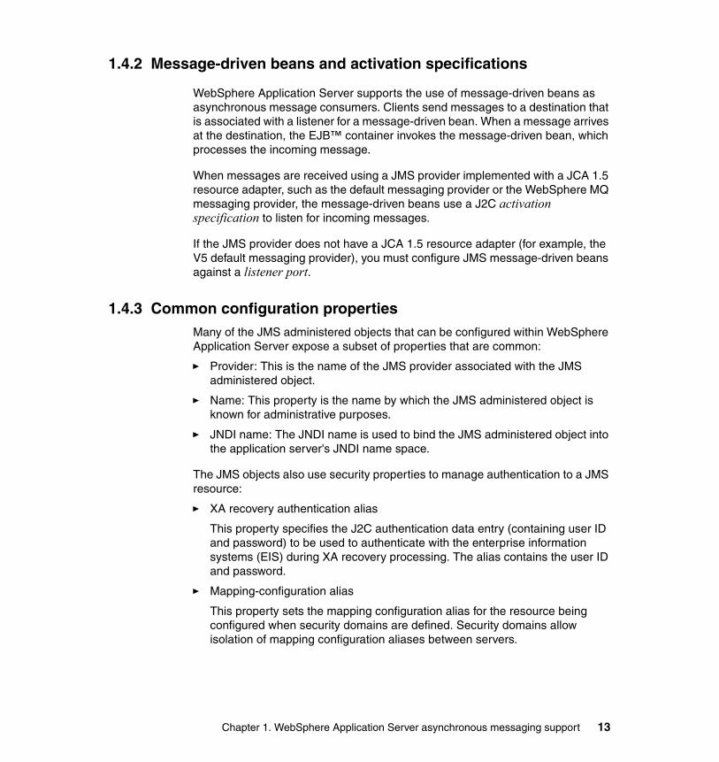
1.4.2 Message-driven beans and activation specifications
WebSphere Application Server supports the use of message-driven beans as asynchronous message consumers. Clients send messages to a destination that is associated with a listener for a message-driven bean. When a message arrives at the destination, the EJB™ container invokes the message-driven bean, which processes the incoming message.
When messages are received using a JMS provider implemented with a JCA 1.5 resource adapter, such as the default messaging provider or the WebSphere MQ messaging provider, the message-driven beans use a J2C activation specification to listen for incoming messages.
If the JMS provider does not have a JCA 1.5 resource adapter (for example, the V5 default messaging provider), you must configure JMS message-driven beans against a listener port.
1.4.3 Common configuration propertiesMany of the JMS administered objects that can be configured within WebSphere Application Server expose a subset of properties that are common:
� Provider: This is the name of the JMS provider associated with the JMS administered object.
� Name: This property is the name by which the JMS administered object is known for administrative purposes.
� JNDI name: The JNDI name is used to bind the JMS administered object into the application server's JNDI name space.
The JMS objects also use security properties to manage authentication to a JMS resource:
� XA recovery authentication alias
This property specifies the J2C authentication data entry (containing user ID and password) to be used to authenticate with the enterprise information systems (EIS) during XA recovery processing. The alias contains the user ID and password.
� Mapping-configuration alias
This property sets the mapping configuration alias for the resource being configured when security domains are defined. Security domains allow isolation of mapping configuration aliases between servers.
Chapter 1. WebSphere Application Server asynchronous messaging support 13

� Container-managed authentication alias
This property specifies the J2C authentication data entry (containing user ID and password) to be used to provide security credentials.
1.5 Configuring the default messaging provider
Figure 1-5 shows a high-level view of the components that must be configured to enable a messaging application to use the default messaging provider.
Figure 1-5 High-level view of components
The sections that follow describe how to configure connection factories and destinations for the default messaging provider.
1.5.1 Configuring a connection factory
To configure a JMS connection factory for the default messaging provider, complete the following steps:
1. If you have not created a service integration bus, create it now (see 3.3, “Creating a bus” on page 158). In this example, a bus called SampleBus has been created.
2. In the navigation tree, expand Resources → JMS → Connection factories and set the scope.
// Get the connection factoryConnectionFactory connFactory = (ConnectionFactory) initCtx.lookup(“java:comp/env/jms/SampleJMSConnFactory”);
// Get the destination used to send a messageDestination destination = (Destination) initCtx.lookup(“java:comp/env/jms/SampleJMSQueue”);
JMS Destination Type=Queue JNDI name = jms/SampleJMSQueue Bus name=SampleBus Queue name = SampleJMSQueue
JMS Connection FactoryJNDI name = jms/SampleJMSConnFactoryBus = SampleBus
Default Messaging JMS ProviderMessaging Application
// Create the message producerMessageProducer msgProducer = session.createProducer(destination);
// Create the messageTextMessage txtMsg = session.createTextMessage(“Hello World”);
// Send the messagemsgProducer.send(txtMsg);
Service Integration Bus
Bus=SampleBus
Destination
Queue=SampleJMSQueue
Messaging Application
14 WebSphere Application Server V7 Messaging Administration Guide

3. To create a new JMS connection factory object, click New and select the Default messaging provider option. Click OK.
Figure 1-6 shows the top portion of the configuration page for the connection factory object. The only required properties are:
– Name– JNDI name– Bus name– Security settings if bus security has been enabled
In this example, the SampleJMSConnFactory will connect to SampleBus. The JMS application will access the factory using the JNDI name jms/SampleJMSConnFactory.
Figure 1-6 Default messaging JMS connection factory properties
Chapter 1. WebSphere Application Server asynchronous messaging support 15

Enter any configuration properties required for this specific connection factory (these are discussed in the next section).
Click OK.
You will see the new connection factory in the collection table (Figure 1-7).
Figure 1-7 Default messaging JMS connection factory administered objects
4. Save the changes and synchronize them with the nodes.
JMS connection factory propertiesThe JMS connection factory properties for the default messaging provider are briefly discussed here to give you an idea of the capabilities available. Detailed help is available from both the WebSphere Information Center and using the help in the administrative console. The Information Center article is “Default messaging provider unified connection factory [Settings],” available at:
http://publib.boulder.ibm.com/infocenter/wasinfo/v7r0/index.jsp?topic=/com.ibm.websphere.pmc.nd.doc/sibjmsresources/SIBJMSConnectionFactory_DetailForm.html
16 WebSphere Application Server V7 Messaging Administration Guide

Connection properties to select the bus and messaging engineWhen a JMS client connects to a service integration bus, it connects to an individual messaging engine that is part of that bus. The connection properties, shown in Figure 1-8, determine to which messaging engine a client connects.
Figure 1-8 Connection factory connection properties
Specifying only the bus name will connect clients to any suitable messaging engine within the named service integration bus.
You can fine-tune the selection of the messaging engine using the target and target type properties. These properties allow you to specify a messaging engine or group, while the target significance and target inbound transport chain properties can be used to influence the selection.
If the client application is not running in the WebSphere Application Server environment or if the target bus is in another cell, the provider endpoints and connection proximity properties can be used to specify the bootstrap server to be used to find the messaging engine and the proximity of that messaging engine to the bootstrap server (on the same bus, cluster, server, or host).
Chapter 1. WebSphere Application Server asynchronous messaging support 17
Detailed information about the connection properties and how they can be used to select specific messaging engines can be found in the article “Administrative properties for JMS connections to a bus,” available at:
http://publib.boulder.ibm.com/infocenter/wasinfo/v7r0/index.jsp?topic=/com.ibm.websphere.pmc.nd.doc/sibjmsresources/ujb0001_.html
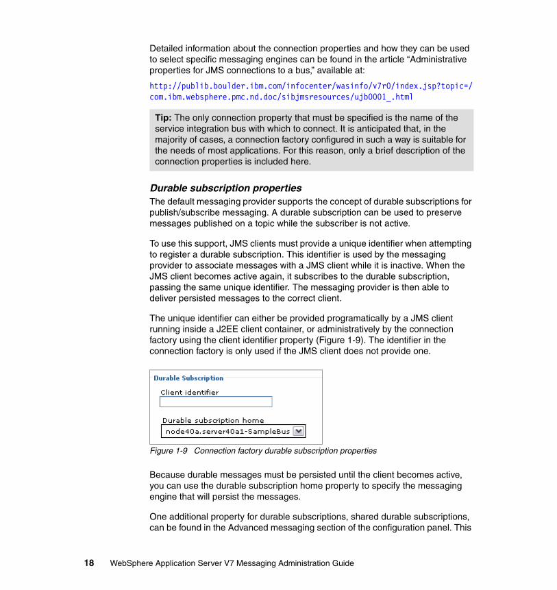
Durable subscription propertiesThe default messaging provider supports the concept of durable subscriptions for publish/subscribe messaging. A durable subscription can be used to preserve messages published on a topic while the subscriber is not active.
To use this support, JMS clients must provide a unique identifier when attempting to register a durable subscription. This identifier is used by the messaging provider to associate messages with a JMS client while it is inactive. When the JMS client becomes active again, it subscribes to the durable subscription, passing the same unique identifier. The messaging provider is then able to deliver persisted messages to the correct client.
The unique identifier can either be provided programatically by a JMS client running inside a J2EE client container, or administratively by the connection factory using the client identifier property (Figure 1-9). The identifier in the connection factory is only used if the JMS client does not provide one.
Figure 1-9 Connection factory durable subscription properties
Because durable messages must be persisted until the client becomes active, you can use the durable subscription home property to specify the messaging engine that will persist the messages.
One additional property for durable subscriptions, shared durable subscriptions, can be found in the Advanced messaging section of the configuration panel. This
Tip: The only connection property that must be specified is the name of the service integration bus with which to connect. It is anticipated that, in the majority of cases, a connection factory configured in such a way is suitable for the needs of most applications. For this reason, only a brief description of the connection properties is included here.
18 WebSphere Application Server V7 Messaging Administration Guide

property specifies whether multiple TopicSubscribers, created using this connection factory, can consume messages simultaneously from a single durable subscription. Normally, only one session at a time can have a TopicSubscriber for a particular durable subscription. This property enables you to override this behavior, to enable a durable subscription to have multiple simultaneous consumers.
For more information about durable subscriptions, see “Using durable subscriptions” at:
http://publib.boulder.ibm.com/infocenter/wasinfo/v7r0/topic/com.ibm.websphere.pmc.nd.multiplatform.doc/tasks/tjn0012_.html
Quality of service properties: PersistenceThe JMS specification supports two modes of delivery for JMS messages:
� Persistent � Non-persistent
However, the service integration bus defines several levels of reliability that can be applied to both persistent and non-persistent messages.
Figure 1-10 Connection factory quality of service properties
The quality of service properties enable an administrator to define the reliability applied to messages sent using connections created from this connection factory.
More information about the reliability levels can be found in “Message reliability levels” at:
http://publib.boulder.ibm.com/infocenter/wasinfo/v7r0/topic/com.ibm.websphere.pmc.nd.multiplatform.doc/concepts/cjj9000_.html
Advanced properties: Read aheadRead ahead is an optimization technique used by the default messaging provider to reduce the time taken to satisfy requests from message consuming applications running in different JVMs from the JVM running the messaging engine where the messages are stored. It works by pre-emptively assigning
Chapter 1. WebSphere Application Server asynchronous messaging support 19
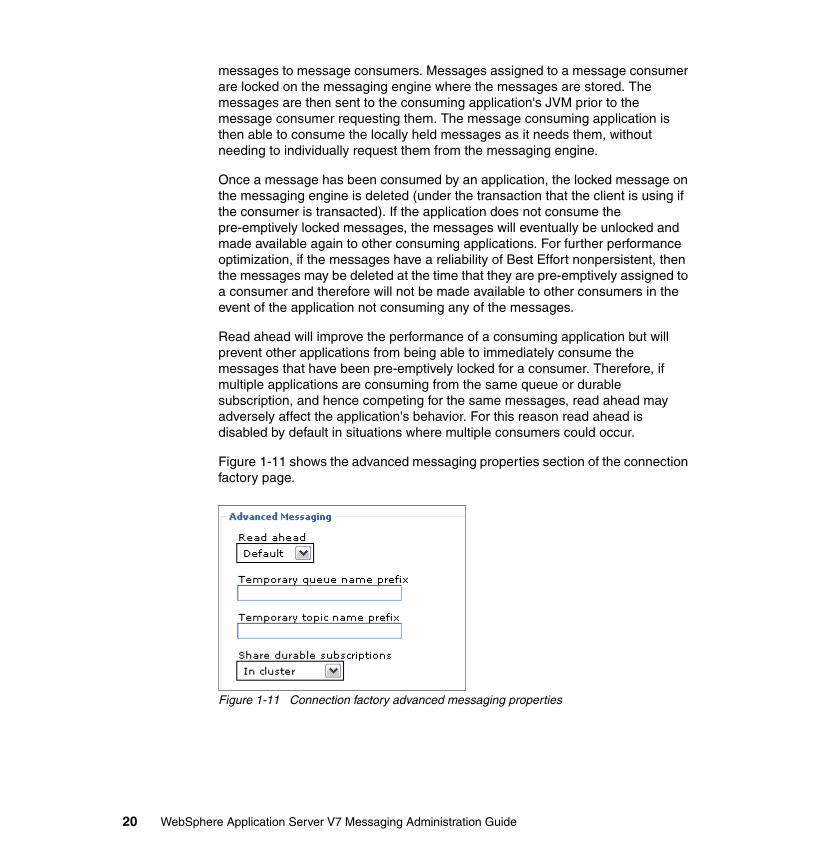
messages to message consumers. Messages assigned to a message consumer are locked on the messaging engine where the messages are stored. The messages are then sent to the consuming application's JVM prior to the message consumer requesting them. The message consuming application is then able to consume the locally held messages as it needs them, without needing to individually request them from the messaging engine.
Once a message has been consumed by an application, the locked message on the messaging engine is deleted (under the transaction that the client is using if the consumer is transacted). If the application does not consume the pre-emptively locked messages, the messages will eventually be unlocked and made available again to other consuming applications. For further performance optimization, if the messages have a reliability of Best Effort nonpersistent, then the messages may be deleted at the time that they are pre-emptively assigned to a consumer and therefore will not be made available to other consumers in the event of the application not consuming any of the messages.
Read ahead will improve the performance of a consuming application but will prevent other applications from being able to immediately consume the messages that have been pre-emptively locked for a consumer. Therefore, if multiple applications are consuming from the same queue or durable subscription, and hence competing for the same messages, read ahead may adversely affect the application's behavior. For this reason read ahead is disabled by default in situations where multiple consumers could occur.
Figure 1-11 shows the advanced messaging properties section of the connection factory page.
Figure 1-11 Connection factory advanced messaging properties
20 WebSphere Application Server V7 Messaging Administration Guide

Valid values for this property are:
� Default: Read ahead is enabled in situations where there can only be a single message consumer. That is, read ahead is enabled for message consumers of non-durable subscriptions and unshared durable subscriptions. This is the default value for this property.
� Enabled: Read ahead is enabled for all message consumers.
� Disabled: Read ahead is disabled for all message consumers.
The read ahead property for the connection factory can be overridden by specifying a value for the read ahead property on a specific JMS destination.
Advanced properties: Temporary namesYou can also specify prefixes to be used on temporary queues and topics created within JMS clients that are using this connection factory.
Pass message payload by referenceWhen large object messages or bytes messages are sent, the cost in memory and processor use of serializing, deserializing, and copying the message payload can be significant. If you enable the pass message payload by reference properties on a connection factory or activation specification, you tell the default messaging provider to override the JMS 1.1 specification and potentially reduce or bypass this data copying. This feature is enabled separately for messages sent and received (Figure 1-12).
Figure 1-12 Connection factory pass message payload by reference properties
When these settings are enabled, applications that use the connection factory to send messages will not have their data copied, and the system will only serialize the message data when absolutely necessary with this property set. Applications
Chapter 1. WebSphere Application Server asynchronous messaging support 21

that receive messages using this connection factory will only have the message data serialized by the system when absolutely necessary with this property set.
Advanced administrative propertiesThe connection factory for the default messaging provider also exposes a number of advanced properties that are used for administrative purposes.
These properties allow you to do the following:
� Log missing transaction contexts.
Specify whether the Web or EJB container logs the fact that there is no transaction context associated with the thread on which a connection is obtained. This situation can occur if an application has created its own threads. The log entry is written to the SystemOut.log file. The default value for this property is false. The check box is not selected.
� Manage cached handles.
Specify whether the Web or EJB container tracks connection handles that have been cached by an application. An application caches connection handles by storing them in instance variables. If the application subsequently fails, the Web or EJB container will attempt to close any connections that it was using. However, tracking cached connection handles incurs a large runtime performance overhead and should only be used for debugging purposes. The default value for this property is false (the check box is not selected).
� Share data source with CMP.
Use this property to enable the sharing of JDBC™ connections between the data store component of a messaging engine and container-managed persistence (CMP) entity beans. In order for this to provide a performance improvement, the data source used by the data store and the CMP entity bean must be the same. If this is the case, a JDBC connection can be shared within the context of a global transaction involving the messaging engine and the CMP entity bean. If no other resources are accessed as part of the global transaction, WebSphere is able to use local transaction optimization in an effort to improve performance. The default value for this property is false (the check box is not selected).
22 WebSphere Application Server V7 Messaging Administration Guide

Security settingsThe security settings determine the security credentials used for authentication with the JMS provider:
� XA recovery authentication alias
This property specifies the J2C authentication data entry (containing user ID and password) to be used to authenticate the creation of a connection with the JMS provider during XA recovery processing. The alias contains the user ID and password.
XA recovery may require a connection to a messaging engine. When security is enabled for the bus, this authentication alias is used when creating that connection.
� Mapping-configuration alias
This property sets the mapping configuration alias for the resource being configured when security domains are defined. Security domains allow isolation of mapping configuration aliases between servers.
� Container-managed authentication alias
This property specifies the J2C authentication data entry (containing user ID and password) to be used to connect to the bus.
This field will be used in the absence of a loginConfiguration on the component resource reference. The specification of a login configuration and associated properties on the component resource reference determines the container-managed authentication strategy when the res-auth value is Container.
1.5.2 Configuring JMS destinations
Both queue and topic destinations can be configured for the default messaging provider.
JMS queue configurationTo configure a queue destination for the default messaging provider, complete the following steps:
1. Create the queue on the bus (see 3.6.1, “Creating a queue destination” on page 186).
2. In the navigation tree, expand Resources → JMS → Queues and set the scope. To create a new queue destination object, click New.
3. Select Default messaging provider and click OK.
Chapter 1. WebSphere Application Server asynchronous messaging support 23

4. Complete the properties in the configuration page. The only required fields are Name, JNDI name, and Queue name. Figure 1-13 shows a portion of the configuration page containing the required fields.
Figure 1-13 Default messaging queue destination properties
In the example, the value specified for the queue name property is SampleJMSQueue. This must match the name of the queue destination defined on the corresponding service integration bus.
By default, no value is specified for the bus name property. The default behavior when no bus name is specified is to assume that the queue destination is defined on the same bus to which the application is connected. That is, the bus will be determined from the connection factory that is used in conjunction with the JMS queue destination.
Complete the configuration properties and click OK. The properties are discussed in the next section.
24 WebSphere Application Server V7 Messaging Administration Guide

The new queue destination will be created and shown in the collection list (Figure 1-14).
Figure 1-14 New JMS queue for the default messaging provider
5. Save the changes and synchronize them with the nodes.
JMS topic configurationTo configure a topic destination for the default messaging provider, complete the following steps:
1. Create the topic space on the bus (see 3.6.2, “Creating a topic space destination” on page 189).
2. In the navigation tree, expand Resources → JMS → Topics and select the scope.
3. To create a new topic destination object, click New.
4. Select Default messaging provider and click OK.
Chapter 1. WebSphere Application Server asynchronous messaging support 25

5. Complete the properties in the configuration page. Figure 1-15 shows part of the configuration page for the new SoccerTopic object.
Figure 1-15 Default messaging topic destination properties
The required properties are name, JNDI name, and the topic space name on the bus. In our example, the value specified for the topic space property is SoccerTopic. This must match the name of the topic space destination defined on the corresponding service integration bus.
By default, no value is specified for the bus name property. The default behavior when no bus name is specified is to assume that the topic destination is defined on the same service integration bus to which the application is connected. The service integration bus will be determined from the connection factory that is used in conjunction with the JMS topic destination.
26 WebSphere Application Server V7 Messaging Administration Guide

It is also worth noting that the topic name property shown in Figure 1-15 on page 26 has a value of sports/soccer.
The topic name property allows a topic space to be partitioned into a tree-like hierarchical structure. The JMS topic destinations shown in Figure 1-17 on page 28 refer to the SportsTopic destination on the service integration bus. However, they all specify different topic names, as shown in Table 1-1.
Table 1-1 Sample sports topic names
Effectively, this configuration partitions the SportsTopic topic space into the hierarchical structure shown in Figure 1-16.
Figure 1-16 Sample sports topic hierarchy
If a subscriber subscribes to the SoccerTopic JMS destination, which represents the sports/soccer topic name, it will only receive publications sent using the SoccerTopic JMS destination that maps to the same topic name.
However, the SportsTopic JMS destination defines a topic name that ends with a wildcard character. This allows a subscriber interested in all sports to subscribe to the SportsTopic destination. This subscriber would then receive publications sent to either the SoccerTopic, CricketTopic, or BasketballTopic JMS destinations.
6. Once you have entered the configuration properties for the JMS topic destination, click OK.
JMS topic destination Topic name
SportsTopic sports/*
SoccerTopic sports/soccer
CricketTopic sports/cricket
BasketballTopic sports/basketball
Sports
Basketball Cricket Soccer
Chapter 1. WebSphere Application Server asynchronous messaging support 27
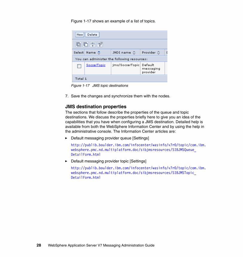
Figure 1-17 shows an example of a list of topics.
Figure 1-17 JMS topic destinations
7. Save the changes and synchronize them with the nodes.
JMS destination propertiesThe sections that follow describe the properties of the queue and topic destinations. We discuss the properties briefly here to give you an idea of the capabilities that you have when configuring a JMS destination. Detailed help is available from both the WebSphere Information Center and by using the help in the administrative console. The Information Center articles are:
� Default messaging provider queue [Settings]
http://publib.boulder.ibm.com/infocenter/wasinfo/v7r0/topic/com.ibm.websphere.pmc.nd.multiplatform.doc/sibjmsresources/SIBJMSQueue_DetailForm.html
� Default messaging provider topic [Settings]
http://publib.boulder.ibm.com/infocenter/wasinfo/v7r0/topic/com.ibm.websphere.pmc.nd.multiplatform.doc/sibjmsresources/SIBJMSTopic_DetailForm.html
28 WebSphere Application Server V7 Messaging Administration Guide

Common propertiesJMS queue and JMS topic destinations share a number of common properties.These are primarily found in the connection area (Figure 1-18).
Figure 1-18 Destination connection properties
The bus name property is used to specify the bus on which the destination is defined. If no value is specified for this property, we assume that the destination is defined on the same service integration bus to which the application is connected. That is, the service integration bus will be determined from the connection factory that is used in conjunction with this JMS destination.
The only situation in which a bus name must be specified is when the underlying destination that this JMS destination refers to is defined on a foreign bus. The foreign bus specified can refer to a service integration bus or to WebSphere MQ. Refer to 2.1.6, “Foreign bus connections” on page 80, for more information.
The following connection properties can be used to override settings from the JMS client:
� The delivery mode property is used to specify the persistence settings (persistent or nonpersistent) for messages that are sent to this destination. The default (application) indicates that the persistence is determined by the client application.
� The time to live property specifies the length of time, in milliseconds, from its dispatch time that a message sent to this destination should be kept by the system. A value of 0 (zero) means that messages are kept indefinitely. By default, no value is specified for this property, allowing the JMS client application to determine the time to keep messages.
Chapter 1. WebSphere Application Server asynchronous messaging support 29

� The message priority setting specifies the relative priority for messages sent to this destination. The JMS specification defines 10 levels of priority ranging from 0 (zero) to 9. Zero is the lowest priority and 9 is the highest. By default, no value is specified for this property, allowing the JMS client application to determine the priority for a message. If the JMS client application does not specify a priority, the default JMS priority of 4 will be used.
The JMS queue and JMS topic destinations also allow you to override the read ahead property setting on the connection factory.
Queue-specific propertiesThe queue name property specifies the name of the queue destination on the underlying service integration bus or foreign bus. If this JMS destination refers to a destination defined on WebSphere MQ through a foreign bus, special consideration must be given to the queue name specified. Refer to “Addressing destinations across the WebSphere MQ link” on page 114 for more information.
(New in V7) Properties in the queue destination now provide you with finer control over sending messages to a bus queue with multiple queue points, hosted on a multi-messaging engine cluster bus member. This control includes the ability to create an affinity between sets of messages and a single queue point, the ability to workload balance messages across queue points in a wider range of topologies, and the ability to scope individual messages and reply messages to specific queue points of a clustered queue. These abilities allow clustered queues to be used in many more messaging topologies than in previous releases, enabling better scaling solutions to be applied.
This release also allows a service integration bus queue with multiple queue points to be seen by a message consumer as a single collection of messages, rather than a set of discrete collections. This new feature allows a single consuming application to have all messages on any of the queue points available to it from anywhere in the bus, removing the need for a consumer to carefully check each queue point individually for messages.
30 WebSphere Application Server V7 Messaging Administration Guide

Figure 1-19 shows these settings.
Figure 1-19 JMS queue properties for control across multiple queue points
For information about these settings, see “Performing request/reply JMS messaging with a scalable bus member” at:
http://publib.boulder.ibm.com/infocenter/wasinfo/v7r0/topic/com.ibm.websphere.pmc.nd.multiplatform.doc/concepts/cjt0020_.html
Topic-specific connection propertiesThe topic space property is used to specify the name of the topic space destination on the bus.
The topic name property allows a topic space to be partitioned into a tree-like hierarchical structure. Several JMS topic destinations can be defined that refer to different nodes of this tree structure within the same underlying topic space on a service integration bus. If no value is specified for this property the topic name defaults to the value specified for the name property for this JMS topic destination.
Chapter 1. WebSphere Application Server asynchronous messaging support 31

The topic name property also allows the use of wildcard characters. Table 1-2 describes the wildcard characters that can be used when specifying the topic name.
Table 1-2 Service integration bus topic wildcard characters
Refer to the WebSphere Information Center for a full description of using topic wild cards in topic expressions to retrieve topics provided by the default messaging provider and service integration bus.
Topic name Topics selected
A/B Selects the B child of A
A/* Selects all children of A
A//* Selects all descendents of A
A//. Selects A and all descendents of A
//* Selects everything
A/./B Equivalent to A/B
A/*/B Selects all B grandchildren of A
A//B Selects all B descendents of A
//A Selects all A elements at any level
* Selects all first level elements
Note: The use of wildcards within a topic name for a JMS topic destination is only valid when the JMS topic destination is used by a message consumer. If a message producer attempts to use such a JMS topic destination, a JMS exception will be thrown to the JMS client application.
32 WebSphere Application Server V7 Messaging Administration Guide
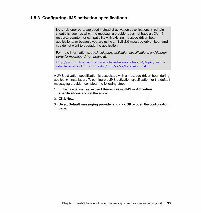
1.5.3 Configuring JMS activation specifications
A JMS activation specification is associated with a message-driven bean during application installation. To configure a JMS activation specification for the default messaging provider, complete the following steps:
1. In the navigation tree, expand Resources → JMS → Activation specifications and set the scope.
2. Click New.
3. Select Default messaging provider and click OK to open the configuration page.
Note: Listener ports are used instead of activation specifications in certain situations, such as when the messaging provider does not have a JCA 1.5 resource adapter, for compatibility with existing message-driven bean applications, or because you are using an EJB 2.0 message-driven bean and you do not want to upgrade the application.
For more information see Administering activation specifications and listener ports for message-driven beans at:
http://publib.boulder.ibm.com/infocenter/wasinfo/v7r0/topic/com.ibm.websphere.nd.multiplatform.doc/info/ae/ae/tm_admin.html
Chapter 1. WebSphere Application Server asynchronous messaging support 33
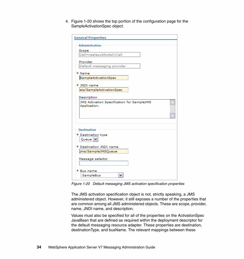
4. Figure 1-20 shows the top portion of the configuration page for the SampleActivationSpec object.
Figure 1-20 Default messaging JMS activation specification properties
The JMS activation specification object is not, strictly speaking, a JMS administered object. However, it still exposes a number of the properties that are common among all JMS administered objects. These are scope, provider, name, JNDI name, and description.
Values must also be specified for all of the properties on the ActivationSpec JavaBean that are defined as required within the deployment descriptor for the default messaging resource adapter. These properties are destination, destinationType, and busName. The relevant mappings between these
34 WebSphere Application Server V7 Messaging Administration Guide
properties and the corresponding properties on the JMS activation specification are shown in Table 1-3.
Table 1-3 Required properties for a JMS activation specification object
Following our example, we know that the SampleJMSQueue object was bound into the JNDI name space with the name jms/SampleJMSQueue. This JMS queue object maps on to the SampleJMSQueue on the SamplesBus service integration bus.
Therefore, if a message-driven bean is associated with this JMS activation specification, it would be invoked when messages arrived at the SampleJMSQueue destination on the SamplesBus.
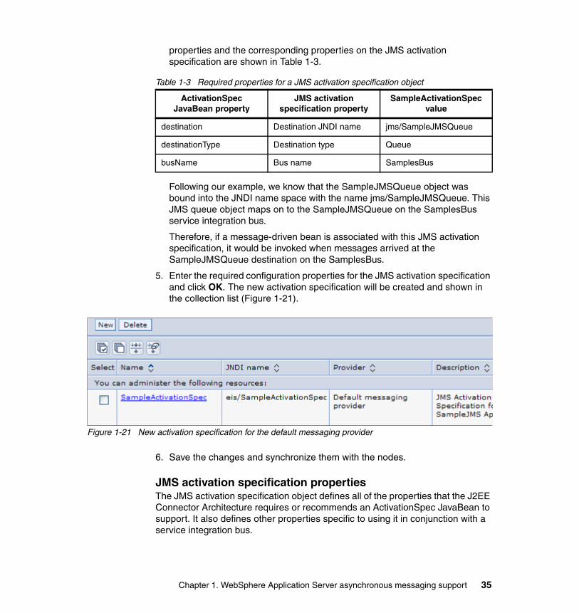
5. Enter the required configuration properties for the JMS activation specification and click OK. The new activation specification will be created and shown in the collection list (Figure 1-21).
Figure 1-21 New activation specification for the default messaging provider
6. Save the changes and synchronize them with the nodes.
JMS activation specification propertiesThe JMS activation specification object defines all of the properties that the J2EE Connector Architecture requires or recommends an ActivationSpec JavaBean to support. It also defines other properties specific to using it in conjunction with a service integration bus.
ActivationSpec JavaBean property
JMS activation specification property
SampleActivationSpec value
destination Destination JNDI name jms/SampleJMSQueue
destinationType Destination type Queue
busName Bus name SamplesBus
Chapter 1. WebSphere Application Server asynchronous messaging support 35

We discuss the properties briefly here to give you an idea of the capabilities that you have when configuring a JMS activation specification. Detailed help is available from both the WebSphere Information Center and by using the help in the administrative console. The Information Center article “JMS activation specification [Settings],” and is available at:
http://publib.boulder.ibm.com/infocenter/wasinfo/v7r0/topic/com.ibm.websphere.pmc.nd.multiplatform.doc/sibjmsresources/SIBJMSActivationSpec_DetailForm.html
The sections that follow describe the properties organized as you will see them grouped in the administrative console:
Destination propertiesThe JMS activation specification defines a number of properties that identify the destination with which a message-driven bean will be associated. When messages arrive on this destination, the message-driven bean will be invoked and the messages passed to it.
The destination type (queue or topic) and destination JNDI name are used to specify how the message-driven bean will look up the JMS destination in the JNDI name space.
The bus name property specifies the bus where the target destination is defined. In previous versions, the message-driven bean had to be running on an application server in the same cell as the bus. In V7 you can use the provider endpoints to connect to a bus in a remote cell.
You can fine-tune the selection of the messaging engine using the target and target type properties. These properties allow you to specify a messaging engine or group, while the target significance and target inbound transport chain properties can be used to influence the selection.
Note: JMS activation specifications also expose the following administration properties:
� Provider� Name� JNDI name
A description for these properties can be found in 1.4.3, “Common configuration properties” on page 13.
Tip: The best performance will be obtained if the application server on which the message-driven bean is running is a member of the bus specified.
36 WebSphere Application Server V7 Messaging Administration Guide

If the client application is not running in the WebSphere Application Server environment or if the target bus is in another cell, the provider endpoints and connection proximity properties can be used to specify the bootstrap server to be used to find the messaging engine and the proximity of that messaging engine to the bootstrap server (on the same bus, cluster, server, or host).
Detailed information about the connection properties and how they can be used to select specific messaging engines can be found in “Administrative properties for JMS connections to a bus,” available at:
http://publib.boulder.ibm.com/infocenter/wasinfo/v7r0/index.jsp?topic=/com.ibm.websphere.pmc.nd.doc/sibjmsresources/ujb0001_.html
The message selector property specifies a JMS message selector that should be applied to the target JMS destination. Only messages that match this message selector will be delivered to the message-driven bean. For example, the following message selector selects messages with a message type of car, color of blue, and weight greater than 2500 lbs:
JMSType = 'car' AND color = 'blue' AND weight > 2500
The acknowledge mode property is used to specify how the EJB container acknowledges the receipt of a message by a message-driven bean instance that is using bean-managed transactions. Valid values for this property are:
� Auto-acknowledge
The EJB container automatically acknowledges the delivery of a message when the onMessage method of the message-driven bean successfully returns.
� Duplicates-ok auto-acknowledge
The EJB container lazily acknowledges the delivery of messages to message-driven beans. This can improve performance, but can lead to a message-driven bean receiving a message more than once.
Additional propertiesThe JMS activation specification for the default messaging provider exposes a group of additional properties that allow you to specify the following parameters:
� Maximum batch size specifies the maximum number of messages that can be received from a messaging engine in a single batch. These messages are then delivered serially to an instance of the message-driven bean that is associated with this JMS activation specification. Delivering messages in a batch can improve the performance of the JMS application. However, if message ordering must be maintained across failed deliveries, the batch size should be set to 1. If no value is specified for this property, it defaults to 1.
Chapter 1. WebSphere Application Server asynchronous messaging support 37

� Maximum concurrent endpoints specifies the maximum number of message endpoints to which messages are delivered concurrently. In the case of a JMS activation specification, a message endpoint is a JMS message-driven bean. Increasing this number can improve performance but will also increase the number of running threads within the application server. If message ordering must be maintained across failed deliveries, the number of maximum concurrent endpoints should be set to 1. If no value is specified for this property, it defaults to 10.
� Automatically stop endpoints enables the automatic stopping of an endpoint when the failed message threshold is reached. When the configured value of sequential failed message threshold is reached, the endpoint will be stopped. The delay between failing messages retries property provides the time delay in milliseconds between successive attempts to process a message by the MDB.
Subscription durability propertiesA durable subscription can be used to preserve messages published on a topic while the subscriber is not active. While a message-driven bean might need to register a durable subscription for a topic, it is not able to do so programatically. The subscription durability properties on a JMS activation specification enable a durable subscription to be specified administratively.
The properties in this section allow you to specify a subscription name, the subscription durability (durable or nondurable), and to provide the client identifier property used to associate messages to an inactive client.
Because durable messages must be persisted until the client becomes active, you can use the durable subscription home property to specify the messaging engine that will persist the messages.
One additional property for durable subscriptions, shared durable subscriptions, can be found in the Advanced messaging section of the configuration panel. This property controls whether durable subscriptions are shared across connections with members of a server cluster.
Advanced propertiesThe JMS activation specification for the default messaging provider also exposes the advanced properties described in this section:
� Share data source with CMP.
Use this property to enable the sharing of JDBC connections between the data store component of a messaging engine and container-managed persistence (CMP) entity beans. In order for this to provide a performance improvement, the data source used by the data store and the CMP entity bean must be the same. If this is the case, a JDBC connection can be shared
38 WebSphere Application Server V7 Messaging Administration Guide

within the context of a global transaction involving the messaging engine and the CMP entity bean. If no other resources are accessed as part of the global transaction, WebSphere is able to use local transaction optimization in an effort to improve performance. The default value for this property is false (the check box is not selected).
Refer to the WebSphere Information Center for a full description of this performance optimization.
� Read ahead.
See “Advanced properties: Read ahead” on page 19.
� Always activate MDBs in all servers.
This property allows the MDB application to process messages whether or not the server also hosts a running messaging engine. This property is only used when the MDB application is running on a server that is a member of the bus that the application is targeting. It has no effect when the MDB is running on a server that is not a member of the target bus.
� Retry interval.
This property sets the delay (in seconds) between attempts to connect to a messaging engine.
Security settingsThe authentication alias property specifies the J2C authentication data entry alias to be used to authenticate the creation of a new connection to the JMS provider. The alias encapsulates the user ID and password that will be used to authenticate the creation of the connection.
1.6 Configuring the WebSphere MQ provider
The WebSphere MQ messaging provider can be configured to communicate with WebSphere MQ using a bindings or client connection. These two connectivity options are described below:
� Bindings connection
When used in bindings mode, the WebSphere MQ messaging provider uses the Java Native Interface (JNI™) to call directly into the existing queue manager API, rather than communicating through a network. This provides better performance when connecting to WebSphere MQ than using a client connection.
However, to use a bindings connection, WebSphere MQ and WebSphere Application Server must be installed on the same machine.
Chapter 1. WebSphere Application Server asynchronous messaging support 39

� Client connection
If it is not possible to collocate WebSphere Application Server and WebSphere MQ on the same machine, the WebSphere MQ messaging provider must be configured to connect to WebSphere MQ using TCP/IP. Using a client connection also allows you to perform authorization checks.
Additional considerations must be taken into account when configuring the WebSphere MQ messaging provider to use a client connection, for example:
– Whether the connection must be secured by encrypting the data that flows over the connection
– Whether the connection will go through a firewall
The sections that follow describe the properties exposed by WebSphere MQ connection factories and destinations, and also how to configure connection factories and destinations for the WebSphere MQ messaging provider.
1.6.1 Support for CCDT
A client channel definition table (CCDT) is a binary file that contains information about how to establish a client connection channel to one or more queue managers. A CCDT is either generated by the WebSphere MQ queue manager or with standalone tools.
In WebSphere Application Server V7, information needed by MQ messaging provider connection factories or activation specifications to connect to a WebSphere MQ queue manager can be provided in two ways:
� Enter all the information manually through the various panels of the wizard.� Provide a URL that points to an entry in the CCDT.
1.6.2 Configuring a connection factory
To configure a connection factory for the WebSphere MQ messaging provider, complete the following steps:
1. In the navigation tree, expand Resources → JMS → Connection factories and select the scope to see a list of existing connection factories.
2. To create a new connection factory object, click New.
Note: The actual WebSphere MQ resources, such as queue managers, channels, and queues, must be created using the tools provided with WebSphere MQ.
40 WebSphere Application Server V7 Messaging Administration Guide

3. Specify the WebSphere MQ messaging provider in the next panel and click OK.
4. Specify the name for the connection factory and the JNDI name that binds it to the name space and click Next.
5. Select the connection method. The options are to use a client channel definition table or to enter all the connection information via the wizard (Figure 1-22). Select an option and click Next.
Figure 1-22 Select the connection method
6. The next panels vary depending on the option that you select. For this example we assume that you selected the option to enter all the required information. (The client channel definition table option will be discussed after the example.).
The first step in this path asks for the queue manager or queue sharing group name. The queue manager property provides the name of the WebSphere MQ queue manager. If no queue manager is specified, the connections created by this factory will connect to the default queue manager on the local machine if one exists.
Enter the name and click Next.
Chapter 1. WebSphere Application Server asynchronous messaging support 41

7. The next panel asks for the information required to make the connection:
– Transport
The transport type property defines the connection type. The options for this field are:
• Client
• Bindings
• Bindings, then client (the default)
This option attempts to connect in bindings mode, and if not possible, reverts to client mode.
– Hostname and port
When a client connection is possible (client or bindings, then client is selected), the hostname and port properties define the connection to the WebSphere queue manager. The port must match the listener port defined for the queue manager, for example, 1414.
– Server connection channel
The Server connection channel specifies the channel used for connection to the queue manager. If no channel is specified, the default channel SYSTEM.DEF.SVRCONN is used.
Enter the connection information and click Next.
8. Click the Test connection button to make sure that the connection information that you entered is correct.
9. Review the results of the test and click Finish to create the connection factory.
10.Save the configuration and synchronize with the nodes.
The new MQ connection factory will be created and shown in the collection list (Figure 1-23).
Figure 1-23 New MQ connection factory
42 WebSphere Application Server V7 Messaging Administration Guide

Figure 1-24 shows the top portion of the configuration page for the SampleMQJMSConnFactory object created in this example.
Figure 1-24 WebSphere MQ connection factory properties
Chapter 1. WebSphere Application Server asynchronous messaging support 43
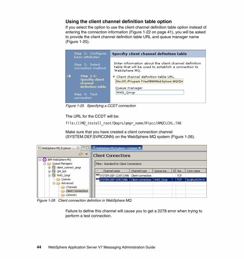
Using the client channel definition table optionIf you select the option to use the client channel definition table option instead of entering the connection information (Figure 1-22 on page 41), you will be asked to provide the client channel definition table URL and queue manager name (Figure 1-25).
Figure 1-25 Specifying a CCDT connection
The URL for the CCDT will be:
file:///MQ_install_root/Qmgrs/qmgr_name/@ipcc/AMQCLCHL.TAB
Make sure that you have created a client connection channel (SYSTEM.DEF.SVRCONN) on the WebSphere MQ system (Figure 1-26).
Figure 1-26 Client connection definition in WebSphere MQ
Failure to define this channel will cause you to get a 2278 error when trying to perform a test connection.
44 WebSphere Application Server V7 Messaging Administration Guide
WebSphere MQ connection factory propertiesA WebSphere MQ connection factory is used to create connections to WebSphere MQ. These connections are used by JMS clients to interact with WebSphere MQ using both the point-to-point and publish/subscribe domains. However, because the WebSphere MQ connection factory is not specific to either domain, it encapsulates all of the configuration information that might be required to communicate using either messaging model. Consequently, a large number of properties are exposed by the WebSphere MQ connection factory object. Fortunately, default values are defined for many of these properties.
To maintain compatibility with JMS specification 1.0, there are two specific types of connection factories (prefixed with Queue and Topic) and a more general type of connection factory with no prefix. The particular properties of specific types of connection factories will be a subset of the more general connection factory, but all are administered in the same way.
The sections that follow describe some of the more important properties that are exposed by the WebSphere MQ connection factory object. The properties have been grouped as seen in the administrative console on the configuration page for the connection factory:
Connection propertiesThe connection properties will contain the fields that you selected when you created the connection factory. You also will have the option to configure SSL.
Security settingsThe security settings allow you to specify the J2C authentication alias entries (containing user ID and password) that will be used to create connections to WebSphere MQ when the connections are secured.
Note: Not all of the properties of the WebSphere MQ connection factory are described. For a full description of all of the properties, refer to the WebSphere Information Center and the help pages in the administrative console.
Chapter 1. WebSphere Application Server asynchronous messaging support 45

Additional propertiesIn the Additional properties area of the configuration page, there are links to advanced properties for specific features. This section provides a summary of the settings you will find in these links. Use the help information in the administrative console and the Information Center for details about these settings:
� Advanced properties
The settings on this link allow you to manage advanced features, including:
– Defining how temporary dynamic destinations are created by providing a queue to use as a model for queue destinations, and a prefix to use in the destination name.
– Message compression.
– Settings that define how messages for the consumers of the connection are handled. This includes how to manage unwanted messages and how long a consumer will wait for a message to appear on a queue before moving on to another queue.
– Message format options, including a coded character set and whether to append an RFH2 header to reply messages.
– Whether to fail JMS method calls if the queue manager is quiescing.
� Broker properties
The settings in this section allow you to define specific characteristics for connections for pub/sub broker (WebSphere Event Broker, WebSphere Message Broker). These settings include queue information for the broker, capability levels of the broker, and subscription controls.
� Client transport properties
The settings in this section allow you to modify connection properties that are used when the JMS resource is used to create a connection to WebSphere MQ. This includes additional SSL settings and channel exits.
� Connection pool properties
The WebSphere MQ connection factory object also exposes some connection pool properties that affect the timing of connection management tasks and performance of the application.
46 WebSphere Application Server V7 Messaging Administration Guide

Connection pool settings should be monitored and adjusted to ensure that WebSphere MQ is not overwhelmed with connections from WebSphere Application Server, while at the same time, applications are not waiting on connections when WebSphere MQ could handle more.
� Session pool properties
The WebSphere MQ connection factory object also exposes session properties, similar to the connection pool properties.
1.6.3 WebSphere MQ destination
To configure a queue destination for the WebSphere MQ messaging provider, complete the following steps:
1. In the navigation tree, expand Resources → JMS → Queues. Set the scope.A list of existing queue destinations defined at this scope will be displayed.
2. To create a new queue destination object, click New.
3. Specify the WebSphere MQ messaging provider and click OK.
Chapter 1. WebSphere Application Server asynchronous messaging support 47

4. The configuration page opens (Figure 1-27). The mandatory fields are name, JNDI name and queue name. The value specified for the queue name property must match the name of the queue defined to the WebSphere MQ queue manager to which you are connecting.
Figure 1-27 WebSphere MQ queue destination properties
Click Apply.
5. Note that the links in the additional properties section become active.
48 WebSphere Application Server V7 Messaging Administration Guide
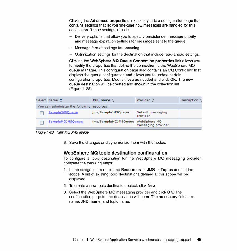
Clicking the Advanced properties link takes you to a configuration page that contains settings that let you fine-tune how messages are handled for this destination. These settings include:
– Delivery options that allow you to specify persistence, message priority, and message expiration settings for messages sent to the queue.
– Message format settings for encoding.
– Optimization settings for the destination that include read-ahead settings.
Clicking the WebSphere MQ Queue Connection properties link allows you to modify the properties that define the connection to the WebSphere MQ queue manager. This configuration page also contains an MQ Config link that displays the queue configuration and allows you to update certain configuration properties. Modify these as needed and click OK. The new queue destination will be created and shown in the collection list (Figure 1-28).
Figure 1-28 New MQ JMS queue
6. Save the changes and synchronize them with the nodes.
WebSphere MQ topic destination configurationTo configure a topic destination for the WebSphere MQ messaging provider,complete the following steps:
1. In the navigation tree, expand Resources → JMS → Topics and set the scope. A list of existing topic destinations defined at this scope will be displayed.
2. To create a new topic destination object, click New.
3. Select the WebSphere MQ messaging provider and click OK. The configuration page for the destination will open. The mandatory fields are name, JNDI name, and topic name.
Chapter 1. WebSphere Application Server asynchronous messaging support 49

In Figure 1-29, the value specified for the topic name property is SampleMQTopic. This must match the name of the topic defined on the broker.
Figure 1-29 WebSphere MQ topic destination properties
50 WebSphere Application Server V7 Messaging Administration Guide

In addition to the name and JNDI name properties, there are four additional properties that you can set on the configuration page:
– Broker durable subscription queue
Specify the name of the brokers queue from which durable subscription messages are retrieved. The subscriber specifies the name of the queue when it registers a subscription. The default value is As connection.
– Broker durable subscriber connection consumer queue
Specify the name of the broker’s queue from which durable subscription messages are retrieved for a ConnectionConsumer. The default value is As connection.
– Broker publication queue
Specify the name of the queue to which publication messages should be sent. The default value is As connection.
– Broker publication queue manager
Specify the name of the queue manager on which the broker is running. The default value is As connection.
Enter the required values and click Apply to activate the links in the Additional Properties section.
4. Clicking the Advanced properties link takes you to a configuration page that contains settings that let you fine-tune how messages are handled for this destination. These settings include:
– Delivery options that allow you to specify persistence, message priority, and message expiration settings for messages sent to the queue.
– Message format settings for encoding.
– Optimization settings for the destination that include read-ahead settings.
Chapter 1. WebSphere Application Server asynchronous messaging support 51
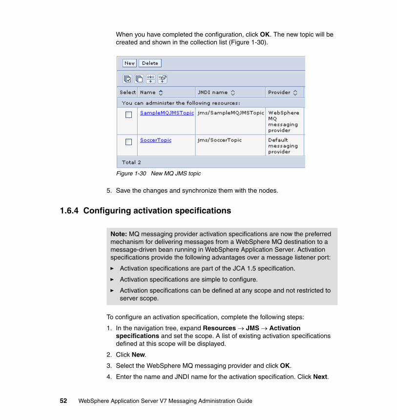
When you have completed the configuration, click OK. The new topic will be created and shown in the collection list (Figure 1-30).
Figure 1-30 New MQ JMS topic
5. Save the changes and synchronize them with the nodes.
1.6.4 Configuring activation specifications
To configure an activation specification, complete the following steps:
1. In the navigation tree, expand Resources → JMS → Activation specifications and set the scope. A list of existing activation specifications defined at this scope will be displayed.
2. Click New.
3. Select the WebSphere MQ messaging provider and click OK.
4. Enter the name and JNDI name for the activation specification. Click Next.
Note: MQ messaging provider activation specifications are now the preferred mechanism for delivering messages from a WebSphere MQ destination to a message-driven bean running in WebSphere Application Server. Activation specifications provide the following advantages over a message listener port:
� Activation specifications are part of the JCA 1.5 specification.
� Activation specifications are simple to configure.
� Activation specifications can be defined at any scope and not restricted to server scope.
52 WebSphere Application Server V7 Messaging Administration Guide
5. Enter the JNDI name and destination type (queue or topic) that defines the destination where the messages will arrive. Optionally, enter a message selector expression that filters the messages to be delivered. Click Next.
6. Select the connection method. You can enter the connection information or use a client channel definition table.
If you select the option to enter the connection information, the next steps will ask for the queue manager or queue sharing group name:
– Queue manager name or queue sharing group name: The queue manager property provides the name of the WebSphere MQ queue manager. If no queue manager is specified, the connections created by this factory will connect to the default queue manager on the local machine if one exists.
– The transport type property defines the connection type. The options for this field are:
• Client
• Bindings
• Bindings, then client (the default)
This option attempts to connect in bindings mode, and if not possible, reverts to client mode.
When a client connection is possible (client or bindings, then client is selected), the hostname and port properties define the connection to the WebSphere queue manager. The port must match the listener port defined for the queue manager, for example, 1414. The server connection channel specifies the channel used for connection to the queue manager. If no channel is specified, the channel defaults to SYSTEM.DEF.SVRCONN. This channel must be defined on WebSphere MQ.
If you select the CCDT option, you will be asked to provide the client channel definition table URL and queue manager name.
Click Next.
7. Test the connection. If the connection is successful, click Next. Otherwise, revisit the connection selections that you made and make sure that the queue manager is available.
8. Review the summary and click Finish.
Chapter 1. WebSphere Application Server asynchronous messaging support 53

9. This will create the activation specification and take you to the list of activation specifications. To view and modify the configuration, click the new activation specification in the list. This opens the configuration page (Figure 1-31).
Figure 1-31 New activation specification
10.Review and modify the properties as needed.
11.Click OK and save the changes.
54 WebSphere Application Server V7 Messaging Administration Guide

1.6.5 Thread pool for WebSphere MQ JMS provider
WebSphere MQ messaging provider uses threads from the WMQCommonServices thread pool to accomplish most of its tasks. Properties for this thread pool can be seen by opening the application server configuration page and selecting Thread pools in the Additional Properties section. The thread pool is shown in Figure 1-32.
Figure 1-32 WebSphere MQ messaging provider thread pool
For details about sizing the thread pools used by the WebSphere MQ messaging provider see:
http://publib.boulder.ibm.com/infocenter/wasinfo/v7r0/index.jsp?topic=/com.ibm.websphere.express.doc/info/exp/ae/tmj_adm34.html
Chapter 1. WebSphere Application Server asynchronous messaging support 55

1.7 Configuring a generic JMS provider
If you use a generic JMS provider, the WebSphere administrative console can still be used to configure JMS administered objects within the JNDI name space of the application server. The sections that follow describe how the WebSphere administrative console can be used to specify a JMS provider, and also to configure JMS connection factories and JMS destinations for that JMS provider.
1.7.1 JMS connection factory configuration
To remain compatible with JMS specification 1.0, there are two specific types of connection factories (prefixed with Queue and Topic) and a more general type of connection factory with no prefix (JMS 1.1). The particular properties of specific types of connection factories will be a subset of the more general connection factory, but all are administered in the same way.
To configure a JMS connection factory for a generic JMS provider, complete the following steps:
1. Make sure that you have installed the provider and defined it to WebSphere. (See 1.3.3, “JMS provider configuration for a generic JMS provider” on page 10.)
2. In the navigation tree, expand Resources → JMS → Connection factories. Set the scope. A list of any existing connection factories defined at this scope will be displayed.
3. To create a new connection factory object, click New.
4. Specify the generic provider in the next panel and click OK. Figure 1-33 on page 57 shows the configuration page for a connection factory object.
56 WebSphere Application Server V7 Messaging Administration Guide

Figure 1-33 Generic JMS provider connection factory configuration panel
Chapter 1. WebSphere Application Server asynchronous messaging support 57

5. Enter the required configuration properties for the JMS connection factory.
In addition to the name and JNDI name properties that you have seen in previous examples, you have the following settings:
– Type
This is a read-only property that is set according to the type of connection factory being configured. For a JMS 1.1 general connection factory, the property will be UNIFIED. For the Queue Connection Factory and Topic Connection Factory, the property will be QUEUE or TOPIC, respectively.
– External JNDI name
Specify the JNDI name used to bind the JMS connection factory into the name space of the messaging provider.
– Component-managed authentication alias
The component-managed authentication alias list can be used to specify a J2C authentication data entry. If the resource reference used within the JMS client application specifies a res-auth of Application, the user ID and password defined by the J2C authentication data entry will be used to authenticate the creation of a connection. The component-managed authentication alias defaults to none. If no component-managed authentication alias is specified and the messaging provider requires the user ID and password to get a connection, then an exception will be thrown when attempting to connect. If using a component-managed alias, the container-managed alias should not be used.
– Mapping-configuration alias
This property provides a list of modules defined at Security → Java Authentication and Authorization Service → Application Logins. The DefaultPrincipalMapping JAAS configuration maps the authentication alias to the user ID and password required by the JMS Provider resource. Other mappings can be defined and used.
– Container-managed authentication alias
The container-managed authentication alias list can be used to specify a J2C authentication data entry. If using a container-managed alias, the component-managed alias should not be used.
Click OK.
6. Save the changes and synchronize them with the nodes.
58 WebSphere Application Server V7 Messaging Administration Guide

1.7.2 JMS destination configuration
There are two types of generic JMS provider destinations:
� Queue � Topic
The properties for both are the same. This section looks at creating a queue destination. To configure a JMS destination for a generic JMS provider, complete the following steps:
1. In the navigation tree, expand Resources → JMS → Queues. Set the scope.
2. Click New.
3. Specify the generic provider in the next panel and click OK. Figure 1-34 shows the configuration page for a destination object.
Figure 1-34 Generic JMS provider queue destination configuration panel
Chapter 1. WebSphere Application Server asynchronous messaging support 59

Enter the required configuration properties for the JMS destination. In addition to the name and JNDI name properties you have seen in previous examples, you must enter the following:
– Type: This is a read-only property set to QUEUE or TOPIC depending on the type of destination being configured.
– External JNDI name: Define the JNDI name used to bind the JMS connection factory into the name space of the messaging provider.
Click OK.
4. Save the changes and synchronize them with the nodes.
5. For the new destination to be bound into the JNDI name space at the correct scope, restart the relevant application servers.
1.8 Thin Client for JMS
The Thin Client for JMS with WebSphere Application Server (hereafter referred to as the Thin Client for JMS) is an embedable technology that provides JMS V1.1 connections to a WebSphere Application Server default messaging provider messaging engine. The Thin Client for JMS is compatible with default messaging provider messaging engines for WebSphere Application Server version 6.0.2 or later.
The client is shipped as a jar file packaged for either a Java application or a Lotus® Expeditor application:
� com.ibm.ws.sib.client.thin.jms_7.0.0.jar: The regular JMS Client
� com.ibm.ws.sib.client_ExpeditorDRE_7.0.0.jar: The JMS Client packaged for Lotus Expeditor
Other files shipped to support the Thin Client for JMS features are:
� sibc.nls.zip: Contains language files needed by the client if using a language other than US-English.
� com.ibm.ws.ejb.thinclient_7.0.0.jar: The Thin Client for EJB is required to add JNDI support to the Thin Client for JMS.
� com.ibm.ws.orb_7.0.0.jar: The IBM ORB is required for Thin Client for JMS applications running in non-IBM JREs.
There is no specific location where the client must be installed. It can be installed in any location on the file system. The client does not require any further configuration after installation, apart from adding the jar files to the classpath for your client application.
60 WebSphere Application Server V7 Messaging Administration Guide

JMS connection factories can be created programmatically (see http://publib.boulder.ibm.com/infocenter/wasinfo/v7r0/index.jsp?topic=/com.ibm.websphere.pmc.nd.doc/tasks/tjj_jmsthcli_connf.html) or by using the JNDI to look up a connection factory defined in WebSphere Application Server. If you are using a JNDI connection factory, a list of provider endpoints must be specified in the connection factory properties to direct the client to the correct location, as shown in Figure 1-35. If required, connections can be secured by configuring SSL settings. See:
http://publib.boulder.ibm.com/infocenter/wasinfo/v7r0/index.jsp?topic=/com.ibm.websphere.nd.doc/info/ae/ae/tcli_securestandaloneclient.html
Figure 1-35 Provider endpoint in a JMS connection factory
Chapter 1. WebSphere Application Server asynchronous messaging support 61

To use the thin client for JMS with WebSphere Application Server V7, follow this procedure:
1. The Thin Client for JMS is located in the /runtimes directory of the WebSphere Application Server installation. You can install the client in any location by copying jar file com.ibm.ws.sib.client.thin.jms_7.0.0.jar from the /runtimes directory.
2. Make sure that com.ibm.ws.sib.client.thin.jms_7.0.0.jar (and optionally com.ibm.ws.ejb.thinclient_7.0.0.jar and com.ibm.ws.orb_7.0.0.jar) is present in the classpath.
3. Compile and execute the JMS client program.
1.9 References and resources
See the following documents and Web sites for more information:
� WebSphere Information Center
http://www.ibm.com/software/webservers/appserv/infocenter.html
� Java Enterprise Edition V5 Specification
http://java.sun.com/javaee/reference/
� J2EE Connector Architecture
http://java.sun.com/j2ee/connector/
� Java Message Service (JMS)
http://java.sun.com/products/jms
� Yusuf, Enterprise Messaging Using JMS and WebSphere, Pearson Education, 2004, ISBN 0131468634
Note: Copy the additional jar files com.ibm.ws.ejb.thinclient_7.0.0.jar, com.ibm.ws.orb_7.0.0.jar, and sibc.nls.zip, as required, from the /runtimes directory.
Note: The thin client is not designed to be executed using the WebSphere Application Server JRE™. It is designed to run from J2SE™. Execution using the WebSphere Application Server JRE is not supported and could result in ORB conflicts.
62 WebSphere Application Server V7 Messaging Administration Guide

� Monson-Haefel, et al, Java Message Service, O’Reilly Media, Incorporated,2000, ISBN 0596000685
� Giotta, et al, Professional JMS, Wrox Press Inc., 2001, ISBN 1861004931
Chapter 1. WebSphere Application Server asynchronous messaging support 63

64 WebSphere Application Server V7 Messaging Administration Guide

Chapter 2. Default messaging provider concepts
In this chapter we describe the concepts behind the service integration bus, focusing on its role as the default messaging provider within WebSphere Application Server. We cover:
� “Concepts and architecture” on page 66� “Runtime components” on page 88� “Service integration bus topologies” on page 122� “High availability and workload management” on page 130� “Service integration bus and message-driven beans” on page 136
2
© Copyright IBM Corp. 2009. All rights reserved. 65

2.1 Concepts and architecture
The service integration bus (or just bus) provides a managed communications framework that supports a variety of message distribution models, reliability options, and network topologies. It provides support for traditional messaging applications, as well as enabling the implementation of service-oriented architectures (SOAs) within the WebSphere Application Server environment.
The service integration bus is the underlying messaging provider for the default messaging provider. The sections that follow discuss each of the concepts in more detail.
2.1.1 Service integration bus
A bus consists of a group of interconnected application servers or clusters of application servers that have been added as members of the bus. Each member has a messaging engine that performs the message processing.
Tip: A bus is defined at the cell level. In a standard configuration, no more than one bus is normally required within a cell. However, a cell can contain any number of buses.
66 WebSphere Application Server V7 Messaging Administration Guide

Resources are created within, or added to, the scope of a specific bus. Simply defining a bus within a cell has no run time impact on any of the components running within a cell. It is not until members are added to a bus that any of the run time components within an application server are affected. Figure 2-1 shows a bus defined within a cell.
Figure 2-1 Service integration buses within a cell
2.1.2 Bus member
A bus member is simply an application server, a cluster of application servers, or an MQ Server that has been added as a member of a bus. Adding an application server, or cluster of application servers, as a member of a bus automatically defines a number of resources on the bus member in question. In terms of the functionality provided by a bus, the most important of the resources that are automatically defined is a messaging engine.
2.1.3 Messaging engines
A messaging engine is the component within an application server that provides the core messaging functionality of a bus. At run time, it is the messaging engines within a bus that communicate and cooperate with each other to provide the messaging capabilities of the bus. A messaging engine is responsible for managing the resources of the bus and provides a connection point to which local and remote client applications can connect.
ApplicationServer 2
ApplicationServer 1
Node Agent
Node 1
Node Agent
Node 2
ApplicationServer 3
ApplicationServer 4
DeploymentManager
Deployment Manager Node
WebSphere Application Server V7 Cell
Chapter 2. Default messaging provider concepts 67

A messaging engine is associated with a bus member. When an application server is added as a member of a bus, a messaging engine is automatically created and associated with this application server. Figure 2-2 shows a cell that contains two buses, each of which has two application servers defined as bus members. The messaging engines (MEs) in application server 2 and application server 3 form the HR department bus. The MEs in application server 1 and application server 4 form the accounts department bus.
Figure 2-2 Messaging engines within bus members
ApplicationServer 2
ApplicationServer 1
Node Agent
Node 1
Node Agent
Node 2
ApplicationServer 3
ApplicationServer 4
DeploymentManager
Deployment Manager Node
WebSphere Application Server V7 Cell
ME
ME
Accounts Department BusMembers = {Application Server 1, Application Server 4}
HR Department BusMembers = {Application Server 2, Application Server 3}
ME
ME
68 WebSphere Application Server V7 Messaging Administration Guide

A messaging engine is a relatively lightweight runtime object. This allows a single application server to host several messaging engines. If an application server is added as a member of multiple buses, that application server is associated with multiple messaging engines, one messaging engine for each bus of which it is a member. In Figure 2-3 you can see that application server 1 is a member of two buses and has two MEs, one per bus.
Figure 2-3 Multiple messaging engines within a single application server
ApplicationServer 2
ApplicationServer 1
Node Agent
Node 1
Node Agent
Node 2
ApplicationServer 3
ApplicationServer 4
DeploymentManager
Deployment Manager Node
WebSphere Application Server V7 Cell
ME
ME
Accounts Department BusMembers = {Application Server 1, Application Server 4}
HR Department BusMembers = {Application Server 2, Application Server 3}
ME
MEME
Payroll Department BusMembers = {Application Server 1}
Chapter 2. Default messaging provider concepts 69

When a cluster of application servers is added as a member of bus, a single messaging engine is automatically created and associated with the application server cluster, regardless of the number of application servers defined as members of the cluster. At run time, this messaging engine is activated within a single application server within the cluster. The application server that is chosen to host the messaging engine will be the first cluster member to start. This is shown in Figure 2-4.
Figure 2-4 An application server cluster as a bus member
ApplicationServer 2
ApplicationServer 1
Node Agent
Node 1
Node Agent
Node 2
Cluster 1Application
Server 3Application
Server 4
DeploymentManager
Deployment Manager Node
WebSphere Application Server V7 Cell
ME
HR Department BusMembers = {Cluster 1}
70 WebSphere Application Server V7 Messaging Administration Guide

However, this messaging engine is able to run within any of the application servers defined as members of the cluster. If the messaging engine or the application server within which it is running should fail, the messaging engine is activated on another available server in the cluster. Therefore, adding an application server cluster as a member of a bus enables failover for messaging engines that are associated with that cluster. This is shown in Figure 2-5.
Figure 2-5 Messaging engine failover within an application server cluster
ApplicationServer 2
ApplicationServer 1
Node Agent
Node 1
Node Agent
Node 2
Cluster 1Application
Server 3Application
Server 4
DeploymentManager
Deployment Manager Node
WebSphere Application Server V7 Cell
ME
HR Department BusMembers = {Cluster 1}
ME
Chapter 2. Default messaging provider concepts 71

Once an application server cluster has been added as a member of a bus, it is also possible to create additional messaging engines and associate them with the cluster. These additional messaging engines can then be configured to run within a specific cluster member, if required. Such a configuration enables a bus to be scaled to meet the needs of applications that generate high message volumes. It also improves the availability of the bus in question. This is shown in Figure 2-6.
Figure 2-6 Messaging engine scalability within an application server cluster
For more information about failover and scalability within the bus, refer to 2.4, “High availability and workload management” on page 130.
ApplicationServer 2
ApplicationServer 1
Node Agent
Node 1
Node Agent
Node 2
Cluster 1Application
Server 3Application
Server 4
HR Department BusMembers = {Cluster 1}
DeploymentManager
Deployment Manager Node
WebSphere Application Server V7 Cell
ME MEME ME
72 WebSphere Application Server V7 Messaging Administration Guide
Messaging engine namingAs discussed previously, when a member is added to a bus, a messaging engine is automatically created and associated with the new bus member. The name of the new messaging engine is generated based on the details of the new bus member, as follows:
� Application server bus members
The format of the messaging engine name generated when an application server is added as a member of a bus is as follows:
node_name.server.name-bus_name
The elements are defined as:
– node_name is the name of the node on which the new bus member is defined.
– server.name is the name of the new application server bus member.
– bus_name is the name of the bus to which the new bus member has been added.
For example:
Node.Server 1-SimpleBus
� Application server cluster bus members
The format of the messaging engine name generated when an application server cluster is added as a member of a bus is as follows:
cluster_name.X-bus_name
The elements of this format are:
– cluster_name is the name of the new application server cluster bus member.
– X is a number that is used to uniquely identify the messaging engine within the cluster. This value starts at 000 and is incremented each time that a new messaging engine is added to the cluster.
– bus_name is the name of the bus to which the new bus member has been added.
For example:
Cluster.000-SimpleBus
2.1.4 Message stores
Every messaging engine defined within a bus has a message store associated with it. A messaging engine uses this message store to persist durable data,
Chapter 2. Default messaging provider concepts 73
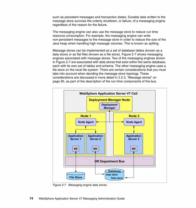
such as persistent messages and transaction states. Durable data written to the message store survives the orderly shutdown, or failure, of a messaging engine, regardless of the reason for the failure.
The messaging engine can also use the message store to reduce run time resource consumption. For example, the messaging engine can write non-persistent messages to the message store in order to reduce the size of the Java heap when handling high message volumes. This is known as spilling.
Message stores can be implemented as a set of database tables (known as a data store) or as flat files (known as a file store). Figure 2-7 shows messaging engines associated with message stores. Two of the messaging engines shown in Figure 2-7 are associated with data stores that exist within the same database, each with its own set of tables and schema. The other messaging engine uses a file store on the local file system. There are certain considerations that you must take into account when deciding the message store topology. These considerations are discussed in more detail in 2.2.3, “Message stores” on page 95, as part of the description of the run time components of the bus.
Figure 2-7 Messaging engine data stores
ApplicationServer 2
ApplicationServer 1
Node Agent
Node 1
Node Agent
Node 2
ApplicationServer 3
HR Department Bus
DeploymentManager
Deployment Manager Node
WebSphere Application Server V7 Cell
MEME ME
File StoreData store
Data store
Database
74 WebSphere Application Server V7 Messaging Administration Guide

2.1.5 Destinations
A destination within a bus is a logical address to which applications can attach as message producers, message consumers, or both, in order to exchange messages. The types of destination that can be configured on a bus are:
� Queue destinations
Queue destinations are destinations that can be configured for point-to-point messaging.
� Topic space destinations
Topic space destinations are destinations that can be configured for publish/subscribe messaging.
� Alias destinations
Alias destinations are destinations that can be configured to refer to another destination, potentially on a foreign bus connection. They can provide an extra level of indirection for messaging applications. An alias destination can also be used to override some of the values specified on the target destination, such as default reliability and maximum reliability. Foreign bus connections are discussed in 2.1.6, “Foreign bus connections” on page 80.
� Foreign destinations
Foreign destinations are not destinations within a bus, but they can be used to override the default reliability and maximum reliability properties of a destination that exists on a foreign bus connection.
Message pointsWhen a destination is configured on a bus, it simply defines a logical address to which applications can attach. Queue and topic space destinations must be associated with a messaging engine in order for any persistent messages directed at those destinations to be persisted to an underlying message store. These destinations are associated with a messaging engine using a message point. A message point is a physical representation of a destination defined on a bus. A message point can be configured to override some of the properties inherited from the bus destination.
Chapter 2. Default messaging provider concepts 75

The two main types of message point that can be contained with a messaging engine are:
� Queue points
A queue point is the message point for a queue destination. When creating a queue destination on a bus, an administrator specifies the bus member that will hold the messages for the queue. This action automatically defines a queue point for each messaging engine associated with the specified bus member.
If the bus member is an application server, a single queue point will be created and associated with the messaging engine on that application server. All of the messages that are sent to the queue destination will be handled by this messaging engine. In this configuration, message ordering is maintained on the queue destination.
If the bus member is a cluster of application servers, a queue point is created and associated with each messaging engine defined within the cluster. The queue destination is partitioned across the available messaging engines within the cluster. In this configuration, message ordering is not maintained on the queue destination. For more information about partitioned destinations within the bus, refer to 2.4, “High availability and workload management” on page 130.
� Publication points
A publication point is the message point for a topic space. Creating a topic space destination automatically defines a publication point on each messaging engine within the bus.
76 WebSphere Application Server V7 Messaging Administration Guide

Figure 2-8 shows a queue destination and a topic space destination and their associated queue and publication points.
Figure 2-8 Queue and publication points in the bus
Node Agent
Node 1
DeploymentManager
Deployment Manager Node
WebSphere Application Server V7 Cell
Accounts Department BusMembers = {Application Server 1, Application Server 2}
ApplicationServer 1
Messaging Engine
Publication Point
Queue DestinationMembers = Application Server 2
Topic SpaceDestination
ApplicationServer 2
Publication Point
Queue Point Message Store
Message Store
Messaging Engine
Chapter 2. Default messaging provider concepts 77

ReliabilityIt is on a destination that an administrator specifies the default quality of service levels that will be applied when a message producer or message consumer interacts with the destination. An administrator is able to configure a default reliability and a maximum reliability for each bus destination. There are five levels of reliability that can be specified for these properties. These are described in Table 2-1.
Table 2-1 Service integration bus destination reliabilities
Administrators can also allow message producers to override the default reliability that is specified on a destination. The mechanism that is used to achieve this depends on the type of the message producer. For instance, a JMS message producer can use the quality of service properties on the JMS
Reliability Description
Best effort nonpersistent Messages that are sent to this destination are discarded when the messaging engine with which it associated is stopped or if it fails. Messages can also be discarded if the connection used to send them becomes unavailable as a result of constrained system resources.
Express nonpersistent Messages that are sent to this destination are discarded when the messaging engine with which it is associated is stopped or fails. Messages can also be discarded if the connection used to send them becomes unavailable.
Reliable nonpersistent Messages that are sent to this destination are discarded when the messaging engine with which it is associated is stopped or fails.
Reliable persistent Messages that are sent to this destination can be discarded when the messaging engine with which it is associated fails, but are persisted if the messaging engine is stopped normally.
Assured persistent Messages that are sent to this destination are never discarded.
Least reliable
Most reliable
Note: Reliability settings should be chosen according to your messaging needs. More reliable qualities of service might not perform as well as less reliable qualities of service.
78 WebSphere Application Server V7 Messaging Administration Guide
connection factory to map the JMS PERSISTENT and NON_PERSISTENT delivery modes onto the required bus reliabilities.
Strict message ordering
Generally, messages going from a single producer to a single consumer will arrive in the same order in which they were produced. However, the order of messages may change due to certain events, such as a system failure of some kind. If a destination is configured to try and enforce message ordering, there are a number of automatic restrictions that come into play at run time. These are:
� Concurrent consumers are prevented from attaching to an ordered destination.
Only a single consumer can attach to an ordered destination at any given time. This is like an exclusive lock that prevents other consumers from attaching and potentially consuming messages out of order.
� Partially consumed messages prevent subsequent messages from being consumed.
Destinations without strict message ordering will allow consumers to skip over messages that have been partially consumed. An example of this is a message that has a lock on it due to an uncommitted transaction. For a destination with strict message ordering, this would result in the destination being blocked until the partially consumed message is fully removed or replaced (committed or rolled back).
� Concurrent message driven beans (MDBs) are restricted for an ordered destination.
To prevent race conditions and ensure ordered processing of MDBs from the destination, the maximum concurrent endpoints and maximum batch size settings of any MDB deployed to an ordered destination are overridden and set to one.
Note: The reliability specified by a message producer can never exceed the maximum reliability specified on a bus destination. In the case of a JMS message producer, attempting to do this will cause a JMS exception to be thrown to the client application.
Note: Destinations on a bus can now be configured to be much more strict in the delivery of messages in the order in which they were produced. When the setting is enabled, certain automatic restrictions are placed on the use of the destination, such as disallowing concurrent consumption of messages by multiple applications, which may disrupt message ordering.
Chapter 2. Default messaging provider concepts 79

There are other issues that should be understood, but cannot be automatically detected at run time. The main ones are listed below:
� If there is an exception destination configured, this may cause messages under error conditions to be directed away from the consumer, thus disrupting the message order. We recommend that for ordered destinations no exception destination be defined.
� Topology changes to the bus, such as deleting and recreating an ordered destination, or introducing or removing mediation, could affect message ordering.
� Alias or foreign destinations do not have a message ordering option. In each case, only the underlying destination can be ordered.
� If a queue destination is deployed to a cluster bus member with more than one messaging engine, this results in a destination with more than one queue point. Message ordering cannot be maintained across such a destination.
� Only messages with a reliability of assured persistent should be used with an ordered destination. Any other reliability levels may result in lost or duplicated messages.
� Multiple producers can send messages to an ordered destination, but messages are presented in the order in which they were committed by the sending transaction. This may be different from the order in which they were written to the queue.
� Messages of different reliabilities can overtake one another. We recommend that messages sent to the ordered destination be of the same reliability level.
� Messages of different priorities can overtake one another. We recommend that messages sent to the ordered destination be of the same priority.
2.1.6 Foreign bus connections
A bus can be configured to connect to, and exchange messages with, other messaging networks. In order to do this, a foreign bus connection must be configured.
Note: Strict message ordering applies to each queue point individually and not across multiple queue points. If a queue is partitioned, ordering across the partitions is not maintained.
80 WebSphere Application Server V7 Messaging Administration Guide

A foreign bus connection encapsulates information related to the remote messaging network, such as the type of the foreign bus connection and whether messaging applications are allowed to send messages to the foreign bus connection. A foreign bus connection can represent:
� A bus in the same cell as the local bus� A bus in a different cell from the local bus� A WebSphere MQ network
The ability of a bus to be able to communicate with other messaging networks provides several benefits, examples of which are:
� It enables the separation of resources for different messaging applications that only need to communicate with each other infrequently. This simplifies the administration of the resources for each individual messaging application.
� It enables a bus to be integrated with preexisting messaging networks.
� It enables messaging to be performed across multiple WebSphere Application Server cells.
When buses are interconnected, applications can send messages to destinations that are defined on other buses. Published messages can also span multiple buses if the links between the buses are configured to allow it.
Note: Care must be taken to avoid creating circular link dependencies (bus A → bus B → bus C → bus A) when configuring foreign bus connections within complex topologies. Circular links are not supported by the bus.
Chapter 2. Default messaging provider concepts 81

Routing definition typesDuring foreign bus connection configuration, an administrator defines a routing definition that specifies the type of the foreign bus connection. This information is used at run time to determine the protocol that will be used to communicate with the foreign bus connection. The three types of routing definition that can be defined are:
� Direct, service integration bus link
This routing definition type indicates that the local bus will connect directly to another bus. This is shown in Figure 2-9, where the accounts department bus is linked to the HR department bus within its own cell and the payroll department bus within another cell.
Figure 2-9 Direct, service integration bus links
� Direct, WebSphere MQ link
This routing definition type indicates that the local bus will connect directly to a WebSphere MQ queue manager. This WebSphere MQ queue manager might itself be connected to several other queue managers in a WebSphere MQ network. This is shown in Figure 2-10.
Figure 2-10 Direct, WebSphere MQ link
WebSphere Application Server V7 CellWebSphere Application Server V7 Cell
HR Department BusForeign Bus = {Accounts
Department Bus}
Accounts Department BusForeign Buses = {HR Department Bus,
Payroll Department Bus}
Payroll Department BusForeign Bus = {Accounts
Department Bus}
WebSphere MQ
Accounts Department BusForeign Bus = {IT Department Bus}
WebSphere Application Server V7 Cell
IT Department Bus
82 WebSphere Application Server V7 Messaging Administration Guide
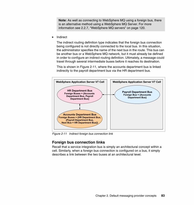
� Indirect
The indirect routing definition type indicates that the foreign bus connection being configured is not directly connected to the local bus. In this situation, the administrator specifies the name of the next bus in the route. This bus can be another bus or a WebSphere MQ network, but it must already be defined in order to configure an indirect routing definition. Ultimately, a message could travel through several intermediate buses before it reaches its destination.
This is shown in Figure 2-11, where the accounts department bus is linked indirectly to the payroll department bus via the HR department bus.
Figure 2-11 Indirect foreign bus connection link
Foreign bus connection linksRecall that a service integration bus is simply an architectural concept within a cell. Similarly, when a foreign bus connection is configured on a bus, it simply describes a link between the two buses at an architectural level.
Note: As well as connecting to WebSphere MQ using a foreign bus, there is an alternative method using a WebSphere MQ Server. For more information see 2.2.7, “WebSphere MQ servers” on page 120.
WebSphere Application Server V7 CellWebSphere Application Server V7 Cell
HR Department BusForeign Buses = {Accounts
Department Bus, Payroll Department Bus}
Accounts Department BusForeign Buses = {HR Department Bus,
{Payroll Department Bus,Next Bus = HR Department Bus}}
Payroll Department BusForeign Bus = {Accounts
Department Bus}
Chapter 2. Default messaging provider concepts 83

In order for the two buses to be able to communicate with each other at run time, links must be configured between a specific messaging engine within the local bus and a specific messaging engine (referred to as a service integration bus link) or queue manager (referred to as an MQ link) within the foreign bus connection. When configuring a direct service integration bus link, these links must be configured in both directions in order for the two buses to be able to communicate. At run time, messages that are routed to a foreign bus connection will flow across the corresponding link. This is shown in Figure 2-12.
Figure 2-12 Run time view of foreign bus connections
Note: It is not possible to define multiple links between the local bus and a specific foreign bus connection.
WebSphere Application Server V7 CellWebSphere Application Server V7 Cell
HR Department Bus
Accounts Department
Bus
Link
LinkME
Link
Link
ME
WebSphere MQ
IT Department Bus
QueueManager
Channels
Payroll Department Bus
Link ME
84 WebSphere Application Server V7 Messaging Administration Guide

Foreign bus connections and point-to-point messagingMessaging applications that make use of the point-to-point messaging model, with destinations that are defined on a local bus, are able to act as both message producers and message consumers. This is shown in Figure 2-13.
Figure 2-13 Point-to-point messaging on the local bus
However, when a messaging application is making use of the point-to-point messaging model with destinations that are defined on a foreign bus connection, it is only able to act as a message producer. This is shown in Figure 2-14.
Figure 2-14 Point-to-point message producer for a foreign bus connection
Local Bus
Produce andConsumeMessages
Client
Local Bus
ProduceMessages
Only
Foreign Bus
Client
Chapter 2. Default messaging provider concepts 85

If a messaging application is required to consume messages from a destination that is defined on a foreign bus connection, the messaging application must connect directly to the foreign bus connection. This is shown in Figure 2-15.
This is similar to the restrictions placed on WebSphere MQ messaging clients, where a client application is only able to consume messages from a queue by connecting directly to the WebSphere MQ queue manager on which the queue is defined.
Figure 2-15 Point-to-point messaging on a foreign bus connection
If the messaging application is unable to connect directly to the foreign bus connection, then the destinations on the foreign bus connection must be configured to forward messages to destinations on the local bus. The messaging application is then able to connect to the local bus to consume the messages. This is shown in Figure 2-16.
Figure 2-16 Forwarding messages for consumption from the local bus
Local Bus Foreign Bus
Produce andConsumeMessages
Client
Local Bus
ConsumeMessages
Foreign BusProduce
Messages
Client
Client
86 WebSphere Application Server V7 Messaging Administration Guide

Foreign bus connections and publish/subscribe messagingBy default, foreign bus connection links will not flow messages that are produced by messaging applications using the publish/subscribe messaging model. It is possible to configure a foreign bus connection link such that messages published to topic spaces on the local bus will be published on the foreign bus connection.
2.1.7 JMS and the default messaging provider
Java EE applications that act as message producers and consumers access the bus through the JMS API. JMS destinations referenced by the applications are associated with bus destinations. Session EJBs use a JMS connection factory to connect to the JMS provider while message-driven beans use a JMS activation specification to connect to the JMS provider. This is illustrated in Figure 2-17.
Figure 2-17 WebSphere default messaging provider and JMS
Note: In WebSphere Application Server V7, a foreign bus and foreign bus links have been combined and referred to as foreign bus connections.
SIBus
Bus Member
JMS Standard API
EJB
JMSConnection
Factory
JMSActivation
Spec
JMSDestination
SIBusDestination
MDB
MessagingEngine(ME)
DataSource
JDBC Provider
Chapter 2. Default messaging provider concepts 87

2.2 Runtime components
At run time, a bus is comprised of a collection of cooperating messaging resources. The sections that follow describe the run time aspects of these messaging resources in more detail.
2.2.1 SIB service
The SIB service is an application server component that is responsible for managing all of the messaging resources that have been associated with a particular application server. Its management tasks include:
� Managing the life cycle of any messaging-related transport chains that have defined within the application server
� Handling inbound connection requests from external messaging applications
Figure 2-18 shows a SIB service within an application server environment.
Figure 2-18 SIB service
Every application server has exactly one SIB service. However, by default the SIB service within an application server is disabled. This ensures that the SIB service does not consume resources unnecessarily if the application server is not hosting any messaging resources.
The process of adding an application server as a member of a bus automatically enables its SIB service. This ensures that the SIB service is available to manage the messaging resources that are created as a result of adding the application server as a bus member.
PORT
Application Server 1
MEME ME
Inbound Transport Chain
PORT
Inbound Transport Chain
SIB Service
88 WebSphere Application Server V7 Messaging Administration Guide

The SIB service can also be manually enabled within an application server that is not a member of a bus. An application server configured in this manner is able to act as a bootstrap server for clients that are running outside of the WebSphere Application Server environment, or for messaging engines that are running in a different cell. Refer to 2.6, “Connecting to a service integration bus” on page 140, for more information regarding bootstrap servers.
Configuration reloadThe SIB service also allows certain configuration changes to be applied to a bus, without requiring a restart of the application servers that are hosting components associated with that bus. The configuration changes that can be applied without an application server restart are:
� Creation, modification, or deletion of a destination� Creation, modification, or deletion of a mediation� Creation of a new bus� Creation of a new messaging engine� Creation of a bus link� Creation of a WebSphere MQ link� Creation of a WebSphere MQ Server
For example, if a new destination is created on a bus, that destination can be made available for use without needing to restart application servers or messaging engines associated with the bus.
2.2.2 Service integration bus transport chains
The SIB service and any messaging engines running within an application server make use of a variety of transport chains in order to communicate with each other and with client applications. The sections that follow describe the inbound and outbound transport chains used by bus components.
Note: To enable dynamic reloading of the SIB configuration files, viz. bus, messaging engine, bus link, WebSphere MQ link, and WebSphere MQ Server for the server, Configuration Reload Enabled must be selected under Servers → Server Types → WebSphere Application Servers → server_name → [Server Messaging] SIB Service. See 3.2, “SIB service” on page 156, for more information.
Chapter 2. Default messaging provider concepts 89

Inbound transport chainsWhen an application server is created using the default template, a number of inbound transport chains are automatically defined. These transport chains enable messaging clients to communicate with a messaging engine. A messaging client can be a client application or another messaging engine. Table 2-2 describes these transport chains.
Table 2-2 Messaging engine inbound transport chains
The SIB service is responsible for managing the life cycle of the messaging-related inbound transport chains within an application server. Certain transport chains can be started even if the application server is not hosting any
Transport chain and associated port
Default port
Client types Description
InboundBasicMessaging
SIB_ENDPOINT_ADDRESS
7276 Remote messaging engines
JMS client applications running in the Java EE client container and using the default messaging provider
This chain allows clients of the specified type to communicate with a messaging engine using the TCP protocol.
InboundSecureMessaging
SIB_ENDPOINT_SECURE_ADDRESS
7286 Remote messaging engines
JMS client applications running in the Java EE client container and using the default messaging provider
This chain allows clients of the specified type to communicate securely with a messaging engine using the secure sockets layer (SSL) protocol over a TCP connection. The SSL configuration information for this chain is based on the default SSL repertoire for the application server.
InboundBasicMQLink
SIB_MQ_ENDPOINT_ ADDRESS
5558 WebSphere MQ queue manager sender channels
This chain allows clients of the specified type to communicate with a messaging engine using the TCP protocol.
InboundSecureMQLink
SIB_MQ_ENDPOINT_SECURE_ADDRESS
5578 WebSphere MQ queue manager sender channels
This chain allows clients of the specified type to communicate securely with a messaging engine using the secure sockets layer (SSL) protocol over a TCP connection. The SSL configuration information for this chain is based on the default SSL repertoire for the application server.
90 WebSphere Application Server V7 Messaging Administration Guide

messaging engines. When a transport chain starts, it binds to the TCP port to which it has been assigned and listens for network connections. Table 2-3 describes the circumstances under which the inbound transport chains are started by the SIB service.
Table 2-3 Default transport chain initialization during application server startup
Figure 2-19 shows the InboundBasicMessaging and InboundSecureMessaging transport chains, and the corresponding ports that they are bound to, within an application server.
Figure 2-19 Messaging engine inbound transport chains
Application server configuration
Transport chains
InboundBasicMessagingInboundSecureMessaging
InboundBasicMQLinkInboundSecureMQLink
SIB service disabled Not started Not started
� SIB service enabled� No WebSphere MQ
links� No WebSphere MQ
client links
Started Not started
� SIB service enabled� WebSphere MQ links� or WebSphere MQ
client links defined
Started Started
Application Server 1
MEME ME
InboundBasicMessaging
SIB_ENDPOINT_ADDRESS
InboundSecureMessaging
SIB_ENDPOINT_SECURE_ADDRESS
SIB Service
Chapter 2. Default messaging provider concepts 91

Outbound transport chainsWhen you create an application server using the default template, a number of outbound transport chains are automatically defined. These transport chains are also available to JMS client applications running within the Java EE client container. Outbound transport chains are used by messaging clients to establish network connections to bootstrap servers or to WebSphere MQ queue manager receiver channels. Table 2-4 describes these transport chains.
Table 2-4 Default messaging engine outbound transport chains
Transport chain Description
BootstrapBasicMessaging This chain is suitable for establishing a bootstrap connection to inbound transport chains within an application server that are configured to use the TCP protocol. An example of such a transport chain is the InboundBasicMessaging chain.
BootstrapSecureMessaging This chain is suitable for establishing a bootstrap connection to inbound transport chains within an application server that are configured to use SSL over a TCP connection. An example of such a transport chain is the InboundSecureMessaging transport chain. Success in establishing such a connection is dependent upon a suitably compatible set of SSL credentials being associated with both this bootstrap outbound transport chain and also the inbound transport chain to which it is connecting. The SSL configuration used is taken from the default SSL repertoire of the application server within which the messaging client is running, or from the relevant configuration file if the messaging client is running within the Java EE client container.
BootstrapTunneledMessaging This chain can be used to tunnel a bootstrap request through the Hypertext Transfer Protocol (HTTP). Before this transport can be used, a corresponding inbound transport chain must be configured on the bootstrap server.
92 WebSphere Application Server V7 Messaging Administration Guide

When attempting to establish a network connection, a messaging client must use an outbound transport chain suitable for connecting to the corresponding target. For example, the BootstrapTunneledMessaging transport chain can only be used to connect to an inbound transport chain that supports bootstrap requests tunneled over the HTTP protocol. Similarly, the OutboundBasicMQLink can only be used to connect to a WebSphere MQ queue manager receiver channel. Refer to 2.6, “Connecting to a service integration bus” on page 140, for more information regarding bootstrap servers.
Configuring outbound transport chains within an application server used for bootstrap purposes is considered to be an advanced administrative task. For this reason, these transport chains can only be altered, or new bootstrap transport chains defined, using the wsadmin command-line environment.
BootstrapTunneledSecureMessaging This chain can be used to tunnel a secure bootstrap request through the Hypertext Transfer Protocol (HTTPS). Success in establishing such a connection is dependent on a suitably compatible set of SSL credentials being associated with both this bootstrap outbound transport chain and the inbound transport chain to which it is connecting. The SSL configuration used is taken from the default SSL repertoire of the application server within which the messaging client is running, or from the relevant configuration file if the messaging client is running within the Java EE client container. Before this transport can be used, a corresponding inbound transport chain must be configured on the bootstrap server.
OutboundBasicMQLink This chain is suitable for establishing a connection to a WebSphere MQ queue manager receiver channel using the TCP protocol.
OutboundSecureMQLink This chain is suitable for establishing a secure connection to a WebSphere MQ queue manager receiver channel that has been configured to accept SSL connections. Success in establishing such a connection is dependent on a suitably compatible set of SSL credentials being associated with both this outbound transport chain and the WebSphere MQ receiver channel to which it is connecting. The SSL configuration for the outbound transport chain is taken from the default SSL repertoire of the application server that is attempting to contact the WebSphere MQ queue manger receiver channel.
Transport chain Description
Chapter 2. Default messaging provider concepts 93
Outbound transport chains within the Java EE client container environment that are used for bootstrap purposes are not configurable. However, certain attributes of the outbound transport chains that are used to establish SSL connections can be customized.
Secure transport considerationsAdditional considerations must be taken into account when using a transport chain that makes use of the SSL protocol to encrypt the traffic that flows over the connection.
Establishing an SSL or HTTPS connection between messaging engines, or between a messaging engine and a JMS application running within the Java EE client container, requires a set of compatible credentials to be supplied by both the party initiating the connection and the party accepting the connection.
Within an application server environment, the credentials used by a secure transport chain can be configured by associating the required SSL repertoire with the relevant SSL channel within the chain. For inbound transport chains, this can be performed using the WebSphere administrative console. By default, secure transport chains within an application server environment are associated with the default SSL repertoire for the cell. When configuring secure communications between two messaging engines, the name of the inbound transport chain on both messaging engines must match in order for the connection to be established. These transport chains must also be configured with compatible SSL credentials. This is true when securing both intra-bus messaging engine connections and inter-bus messaging engine connections.
Within the Java EE client container environment, the credentials used by a secure outbound transport chain are specified in the sib.client.ssl.properties file. Every WebSphere profile has its own copy of this file, contained in the properties subdirectory of the profile. The properties contained within this file specify, among other things, the location of the key store and trust store to be used by the outbound transport chain when attempting to establish a secure connection to a messaging engine.
Note: Any messaging engine that is active on an application server can be contacted by any enabled inbound transport chain. By default, all application servers are created with both secure and insecure transport chains. In order to ensure that a messaging engine can only be contacted using a secure transport chain, it is necessary to either disable or delete the insecure transport chains that are defined on the corresponding application server.
94 WebSphere Application Server V7 Messaging Administration Guide
2.2.3 Message stores
A messaging engine must have a message store (and only one) as a place to preserve persistent and non-persistent data for normal operation and for recovery should a failure occur. This message store can be implemented as a data store or as a file store. The process of adding an application server as a member of a bus automatically creates a messaging engine on that application server. As part of that process wizard, a choice is presented as to which implementation of a message store is required:
� A data store is a message store implemented as a set of database tables within a relational database, accessed via a JDBC data source.
� A file store is a message store implemented as a set of flat files within a file system that is accessed directly via the native operating system.
Both types of message store and considerations for when choosing between them are discussed in the following sections.
File storesA file store for a messaging engine is hosted directly on a file system as a set of flat files via the underlying operating system. The messaging engine does not need any other resources to be set up in order to access the file store. The file store uses three levels of data storage in separate files and locations, as discussed in the following sections.
Chapter 2. Default messaging provider concepts 95
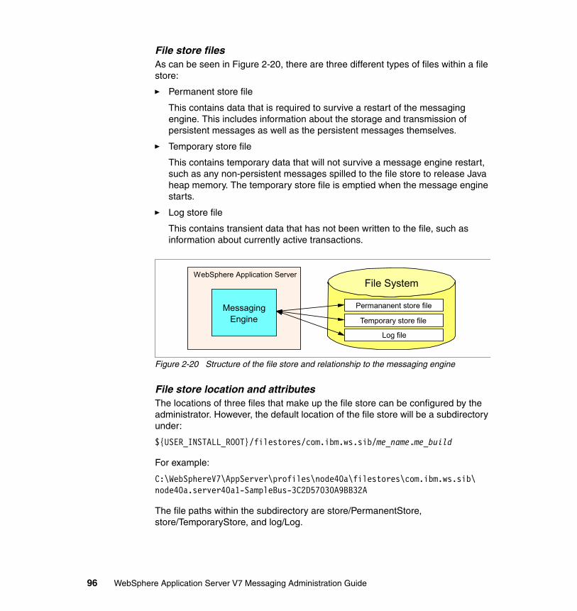
File store filesAs can be seen in Figure 2-20, there are three different types of files within a file store:
� Permanent store file
This contains data that is required to survive a restart of the messaging engine. This includes information about the storage and transmission of persistent messages as well as the persistent messages themselves.
� Temporary store file
This contains temporary data that will not survive a message engine restart, such as any non-persistent messages spilled to the file store to release Java heap memory. The temporary store file is emptied when the message engine starts.
� Log store file
This contains transient data that has not been written to the file, such as information about currently active transactions.
Figure 2-20 Structure of the file store and relationship to the messaging engine
File store location and attributesThe locations of three files that make up the file store can be configured by the administrator. However, the default location of the file store will be a subdirectory under:
${USER_INSTALL_ROOT}/filestores/com.ibm.ws.sib/me_name.me_build
For example:
C:\WebSphereV7\AppServer\profiles\node40a\filestores\com.ibm.ws.sib\node40a.server40a1-SampleBus-3C2D57030A9BB32A
The file paths within the subdirectory are store/PermanentStore, store/TemporaryStore, and log/Log.
WebSphere Application Server
Messaging Engine
File System
Permananent store file
Temporary store file
Log file
96 WebSphere Application Server V7 Messaging Administration Guide

The log file has a fixed size at run time and does not expand during use. The messaging engine writes data to the log file in a sequential manner, meaning that new records are appended to the end. Upon reaching the maximum capacity of the log, the oldest records are overwritten by new records as needed. Any data required to be kept is subsequently written to the permanent and temporary store files as appropriate. Only extremely short-lived data is not moved to a store file. The minimum size for a log file is 10 MB with the default being 100 MB.
Both the permanent and temporary store files have separately configured minimum file sizes of 0 bytes (the default minimum setting is 200 MB). They may also have optional maximum size limits placed on them of at least 50 MB each (the default setting is 500 MB). When created, both the permanent and temporary log files consume file space up to their individual minimum reserve, in addition to the size of the log file. If this does not meet their maximum allocations, then the store files are free to grow. This growth is unlimited if a maximum allocation has not been set.
The default settings and configuration for a file store are designed to be adequate for a typical messaging workload without the need for any administration. However, it is up to the administrator to make sure that enough space is allocated to the file store components for predictable and smooth operation of the messaging engine. To improve the performance and availability of the log or store files, the file store attributes can be modified to affect sizing and placement of the files. This can be done at creation of the filestore or later on.
File store access and high-availability considerationsA messaging engine has exclusive access of its own file store, and a file store can only be used by the messaging engine that created it. Each file store contains uniquely identifying information about its messaging engine. An instance of a messaging engine will open its file store with an exclusive lock to prevent other instances of the same messaging engine from trying to use the file
Note: For a production system, maximum and minimum limits should be applied and set to the same value so that the file sizes are stable. This would prevent unlimited growth from filling up the file system, and allow the messaging engine to continue to operate unaffected should the file system fill up due to external causes.
Note: Optimal operation of a messaging engine cannot be guaranteed where the file store is subject to a compressing file system, such as Windows® Server 2008 with the Compress this directory option active. In a production system, the use of file system compression should be avoided.
Chapter 2. Default messaging provider concepts 97

store at the same time. This situation might arise if there was an accidental activation of a messaging engine on multiple servers within a cluster. When the instance of the messaging engine stops for any reason (either controlled or server failure), the file store’s files are closed, allowing another instance to open the file store.
The major consideration for high availability of a file store is the file system in which it is placed. We recommend using hardware-based or software-based facilities to maximize the availability of the file systems themselves, such as Storage Area Networks (SANs).
WebSphere Application Server V7 supports either cluster-managed or networked file systems. Cluster-managed file systems use clustering and failover of shared disks to ensure high availability of files and directories. Networked file systems use remote servers to store and access files as though it were a local server. Make sure that the file system in use supports access locking to ensure integrity of the file store components, particularly the log file by the use of exclusive locks.
Deleting a file storeWhen a messaging engine is removed, the file store files are not automatically removed with it and must be located and deleted manually in order to reclaim the file’s space. The default file store directory names contain the Universal Unique IDentifier (UUID) of the messaging engine. It is possible to destroy and recreate a messaging engine of the same name without having to manually remove the old file store as the UUID (and so the file store directory names) will have changed. Delete the file store files by using the facilities of the operating system.
Backing up and restoring a file storeA file store is made up of simple flat files. As such, backing up and restoring these files can be done using a backup tool or facilities of the operating system.
Note: Neither the WebSphere administrative console nor the messaging engine can check that the file store configuration is correct. Errors only surface at run time, so we recommend that the administrator conduct a check and thorough failover testing. In particular, ensure that all members of a cluster have universal access to the directories containing the file store components.
Note: It is important that the permanent store file, temporary store file, and log file of a file store be backed up and restored as one unit and not individually. Also, make sure that the messaging engine has been stopped before performing a backup or restore. To do otherwise might result in significant data corruption.
98 WebSphere Application Server V7 Messaging Administration Guide

Reduction of file store sizesWhile it is possible to reduce the file size settings of the file store components in the configuration, it is not possible for the files to actively shrink or compress their contents. When the configuration has been changed and the messaging engine restarted, the messaging engine will attempt to apply the new settings. If the files are still too big due to their contents, a message is written to SystemOut.log and the existing settings are kept. The messaging engine attempts to apply the new settings each time it is started.
Failover of messaging engine between V6 and V7As WebSphere Application Server V6.0 does not support file stores, it is not possible to fail over a messaging engine with a file store to a V6.0 server. To prevent this, the cluster should be divided into sets of servers at different versions, and the high-availability policy of the messaging engine restricted to the servers at V7 and V6.1.
Data storesA data store can be used for a messaging engine hosted within an embedded Derby database. A JDBC data source to access this database is also defined on the server that has been added to the bus. These defaults allow the messaging engine to run without any further configuration.
However, while adding a bus member, it is possible to specify the JNDI name of a different data source for use by the messaging engine. The sections that follow describe the issues that must be considered when deciding which RDBMS to use as a data store.
Data store locationThe data store can be located on the same host as the messaging engine with which it is associated, or it can be located on a remote host. The decision of where to locate the data store might depend on the capabilities of the RDBMS that host the data store. For example, the embedded Derby database must run within the same application server process on which the messaging engine runs.
Note: As stated previously, messaging engine problems may occur if the file store file sizes are too small. Care must be taken to make sure that the sizes are adequate for the expected messaging workload.
Note: Check with your database administrator to ensure that your RDBMS supports remote access from JDBC client applications.
Chapter 2. Default messaging provider concepts 99

The location chosen for the data store can have an impact on the overall performance, reliability, and availability characteristics of the bus components. For example, a data store located on the same host as the messaging engine with which it is associated can provide higher persistent message throughput by avoiding flowing data over the network to the data store. However, such a configuration might not provide the availability required, because failure of the host would mean that both the messaging engine and its data store would become unavailable.
Figure 2-21 shows the various options available when deciding where to locate a data store. The messaging engine in application server 1 uses the default Derby data store, running in the same process as the application server. The messaging engine in application server 2 uses a data store hosted by a DB2® instance running on the same host as node 1. The messaging engine in application server 3 uses a data store hosted by a DB2 instance running on a remote host.
Figure 2-21 Data store locations relative to the associated messaging engine
ApplicationServer 2
ApplicationServer 1
Node Agent
Node 1
Node Agent
Node 2
HR Department Bus
DeploymentManager
Deployment Manager Node
WebSphere Application Server V7 Cell
ME
ApplicationServer 3
ME
DB2
ME Derby DB2
100 WebSphere Application Server V7 Messaging Administration Guide

Data store accessEach messaging engine must have exclusive access to the tables defined within its data store. This can be achieved either by using a separate database from the data store for each messaging engine or by partitioning a single, shared database into multiple data stores using unique schema names for each data store.
Deciding which of these mechanisms to use depends on the capabilities of the RDBMS that will host the data store. For example, the embedded Derby database does not support concurrent access by multiple processes.
Note: Check with your database administrator to ensure that your RDBMS supports shared access from JDBC client applications and that it allows schema names to be specified on a JDBC connection. DB2 supports this functionality.
For databases that do not allow a schema name to be specified on a JDBC connection, multiple messaging engines share database access by each messaging engine using a different user ID when connecting to the database.
Chapter 2. Default messaging provider concepts 101

Figure 2-22 shows the options available when deciding whether to use exclusive access or shared access to a data store. The messaging engine in application server 1 has exclusive access to the database hosting its data store. The messaging engines in application servers 2 and 3 have shared access to the database hosting their data stores. This shared database has been partitioned into separate schemas, with each messaging engine accessing the data store tables within a different schema.
Figure 2-22 Exclusive and shared access to data stores
Data store tablesThe messaging engine expects its data store to contain a set of specific tables, each of which has a specific table definition. Each messaging engine can be configured to create the tables within its data store, if they are not already present. During initialization, a messaging engine connects to its data store and
Node Agent
Node 1
HR Department Bus
DeploymentManager
Deployment Manager Node
WebSphere Application Server V7 Cell
ApplicationServer 1
ME
DB2
SchemaData Store
SchemaData Store
ApplicationServer 2
ME
Node Agent
Node 2
ApplicationServer 3
ME
DB2
SchemaData Store
102 WebSphere Application Server V7 Messaging Administration Guide

checks for the required tables. If the messaging engine has the functionality to create tables, and they do not exist, it attempts to create the tables.
Some organizations allow a database administrator to perform only certain tasks on a database, such as creating tables. In this situation, the database administrator can use the sibDDLGenerator command to generate the DDL statements required to create these tables. The sibDDLGenerator command is located in the \bin\ subdirectory of the WebSphere installation directory. Refer to the WebSphere Information Center for a full description of the sibDDLGenerator command.
Table 2-5 describes the tables defined within the data store for a messaging engine.
Table 2-5 Messaging engine data store tables
Note: In order for the messaging engine to be able to create the required tables within its data store, the user ID for the database must have sufficient privileges. Refer to the WebSphere Information Center for a full description of the database privileges required for the messaging engine to access the data store.
Table name Description
SIBOWNER Ensures exclusive access to the data store by an active messaging engine.
SIBCLASSMAP Catalogs the different object types in the data store.
SIBLISTING Catalogs the SIBnnn tables.
SIBXACTS Maintains the status of active two-phase commit transactions.
SIBKEYS Assigns unique identifiers to objects in the messaging engine.
Chapter 2. Default messaging provider concepts 103

Considerations when choosing the message store type A file store has several advantages over a data store:
� Better performance
A file store can often achieve higher throughput than a data store due to smaller overhead of the file system as compared to that of a relational database.
� Lower administration requirements
There are little or no administration requirements with the use of a file store. A data store may require ongoing database administration, depending on the messaging workload profile, to maintain optimum performance.
� Lower deployment costs
Costs associated with database server licensing and the services of a database administrator do not apply to a file store, as there is no database.
SIBnnn, where nnn is a number Contains persisted objects such as messages and subscription information. These tables hold both persistent and nonpersistent objects, using separate tables for the different types of data, according to the following convention:
� SIB000
Use this name for the table that contains information about the structure of the data in the other two tables.
� SIB001
Use this name for the table that contains persistent objects.
� SIB002
Use this name for the table that contains non-persistent objects saved to the data store to reduce the messaging engine memory requirement.
Note: When you remove a messaging engine, WebSphere Application Server does not automatically delete the tables in its data store. To reuse this data store with another messaging engine, delete the tables within the data store manually.
Table name Description
104 WebSphere Application Server V7 Messaging Administration Guide
However, if an organization already has existing database resources and skills, it may be preferable to use a data store in order to utilize those skills. This applies more to larger companies with a strong team of database administrators.
From a technical standpoint, applications may share the messaging engine’s JDBC connection to a data store to improve performance using a one-phase commit optimization. This is not possible with a file store.
Security for both types of message store can be achieved utilizing the facilities of the underlying infrastructure. For example, file stores can use a secure, possibly encrypted network-attached drive to achieve both electronic and physical security. Data stores can be secured using the available database security facilities.
2.2.4 Exception destinations
If a messaging client encounters a problem when attempting to consume a message from a bus destination, message delivery has failed. The message can be placed back on the bus destination for redelivery. Use the maximum failed deliveries property on a bus destination to determine the number of times that a message can fail delivery. The default value of this property is five.
An exception destination handles undeliverable messages. Both queue and topic space destinations can define an exception destination. If a message cannot be delivered to its intended bus destination, it is rerouted to the specified exception destination. This mechanism prevents the loss of messages that cannot be delivered.
A service integration bus Link (SIBLink) or a WebSphere MQ link can be configured with a specific exception destination. If a link encounters problems with transmitting messages, or if a link is deleted prior to all messages being transmitted, messages may be put to this exception destination.
Note: Messages can also be placed on an exception destination for a variety of other reasons, for example:
� When a destination is deleted, any messages on the destination are placed on the exception destination unless the bus has been configured to discard them.
� When a message is received from a foreign bus connection, the message is placed on the exception destination if the target destination is undefined or has reached its high message threshold, for example.
Chapter 2. Default messaging provider concepts 105

Each messaging engine has a default exception destination of _SYSTEM.Exception.Destinaton.messaging_engine. By default, all bus destinations that have message points on a messaging engine use the default exception destination for that messaging engine when rerouting undeliverable messages. This enables administrators to access all of the undeliverable messages for a messaging engine in one place.
However, an administrator can also configure a bus destination to use a non-default exception destination. This enables administrators to access all of the undeliverable messages for a specific destination in one place, allowing for more fine-grained management of undeliverable messages.
When configuring a destination to use a non-default exception destination, the exception destination specified can be a local or a remote bus destination. We also recommend that this destination is a queue destination and that it exists prior to the creation of the bus destination with which it is associated. If the exception destination specified has been deleted when a destination attempts to reroute an undeliverable message, the undeliverable message is rerouted to the default exception destination for the message engine.
When message order is important, it might be necessary to configure a bus destination not to use an exception destination. In this case, any messages that cannot be delivered to the target destination are not rerouted, and will be redelivered repeatedly. This has the effect of blocking the delivery of subsequent messages to the bus destination in question. For this reason, such a configuration should be used with caution.
Note: It is not possible to delete a default exception destination from a bus. This ensures that there is always a default exception destination available on each messaging engine within the bus.
Note: Errors might occur as a message traverses the bus to its target destination. In this situation, the messaging engine handling the message attempts to redeliver the message. However, if the messaging engine determines that the target destination is unreachable, it can place the message on its default exception destination. For this reason, all exception destinations on the bus must be monitored to ensure that problem messages are processed appropriately.
Note: Publication messages arriving at a topic space destination for which there are no subscribers are not considered to be undeliverable. Such messages are discarded.
106 WebSphere Application Server V7 Messaging Administration Guide

2.2.5 Service integration bus links
Defining a foreign bus connection on a bus simply defines a link between the two buses at an architectural level. When the foreign bus connection in question represents another bus, the link is implemented at run time by establishing a connection between a messaging engine from each of the buses. This link is configured on a messaging engine by defining a service integration bus link. A service integration bus link encapsulates the information required to communicate with a specific messaging engine, within a specific foreign bus connection.
When configuring a service integration bus link, it must be associated with the target foreign bus connection definition. The foreign bus connection definition with which it is associated enables the service integration bus link to determine the name of the target bus. This is shown in Figure 2-23.
Figure 2-23 Association between a service integration bus link and a foreign bus connection
Note: New in V7: Foreign bus connections and their associated links can now be configured using a new foreign bus connection wizard that simplifies the configuration task. The messages queued for transmission across the service integration bus link can now also be managed using the administrative console or via the SIBLinkTransmitter MBean.
WebSphere Application Server V7 Cell
Node 1Application Server 1
Link
SIB Service
Foreign BusName = HR Bus
Accounts Bus
WebSphere Application Server V7 Cell
Node 2Application Server 2
HR ME
SIB Service
HR Bus
Accounts ME
Chapter 2. Default messaging provider concepts 107

This requirement also determines the order in which these objects must be defined. The foreign bus connection must be defined within a bus before a corresponding service integration bus link can be configured on a messaging engine.
When attempting to establish the connection, the messaging engine within the local bus always attempts to connect to the foreign bus connection as though it were a remote client, even if the foreign bus connection is defined within the same cell. For this reason, a list of provider endpoints must also be specified when configuring the service integration bus link. These provider endpoints are used by the messaging engine in the local bus to connect to a bootstrap server in the foreign bus connection. For more information about the bootstrap process, refer to 2.6, “Connecting to a service integration bus” on page 140.
The service integration bus link is also required to specify the name of the messaging engine on the target bus with which to connect. The messaging engine in the local bus uses the bootstrap server to locate the target messaging engine in the foreign bus connection. Figure 2-24 shows this process.
Figure 2-24 Bootstrapping during service integration bus link initialization
Note: The name specified for the foreign bus connection must exactly match the real name of the target bus.
The names of each of the buses involved in the link must also be unique. For this reason, if two buses within separate cells must be linked, care must be taken when naming each of the buses.
WebSphere Application Server V7 Cell
Node 1Application Server 1
LinkAccounts ME
SIB Service
Foreign BusName = HR Bus
Accounts Bus
WebSphere Application Server V7 Cell
Node 2Application Server 2
HR ME
SIB Service
HR Bus
1. Bootstrap
2. Connect
108 WebSphere Application Server V7 Messaging Administration Guide

Once again, this requirement imposes an order in which the various configuration tasks must be performed. Each of the buses involved in the link must have at least one bus member defined before a service integration bus link can be configured.
The final requirement when configuring a service integration bus link is that the link must be configured in both directions in order for the two buses to communicate at run time. This is shown in Figure 2-25.
Figure 2-25 Defining a service integration bus link in both directions
Topic space mappingsBy default, a service integration bus link only flows messages across the link that are addressed to a queue destination on the foreign bus connection. In order to flow publication messages across the service integration bus link, topic space mappings must be configured on the foreign bus connection definition.
Note: The name specified for the service integration bus link within both buses must be the same.
WebSphere Application Server V7 Cell
Node 1Application Server 1
LinkAccounts ME
SIB Service
Foreign BusName = HR Bus
Accounts Bus
WebSphere Application Server V7 Cell
Node 2Application Server 2
HR ME
SIB Service
HR Bus
1. Bootstrap
2. Connect Link HR ME
Foreign BusName = Accounts Bus
Note: If the transport chain used by the service integration bus link encrypts its traffic using SSL, the names of the target inbound transport chain on each link must be the same. The transport chain specified must also be configured identically on each bus to ensure that compatible SSL credentials are used when establishing the link.
Chapter 2. Default messaging provider concepts 109
These mappings define the topic space destination within the local bus for which publication messages are passed over the link. They also define the topic space destination on the foreign bus connection to which these publication messages are addressed. Refer to the WebSphere Information Center for more information regarding the definition of topic space mappings.
2.2.6 WebSphere MQ links
Defining a foreign bus connection on a bus simply defines a link between the two buses at an architectural level. When the foreign bus connection in question represents a WebSphere MQ network, the link is implemented at run time by establishing sender and receiver channels between a specific messaging engine and a WebSphere MQ queue manager. These channels are configured on a messaging engine by defining a WebSphere MQ link.
To a messaging engine configured with a WebSphere MQ link, the WebSphere MQ queue manager appears to be a foreign bus connection. To the WebSphere MQ queue manager, the messaging engine appears to be another WebSphere MQ queue manager. When configuring a WebSphere MQ link, an administrator must specify a virtual queue manager name. This is the queue manager name by which the messaging engine will be known to the remote WebSphere MQ queue manager. The WebSphere MQ queue manager is completely unaware that it is communicating with a messaging engine.
When you configure a WebSphere MQ link, you must associate it with the target foreign bus connection definition. The name specified for the foreign bus connection does not need to match the name of the target WebSphere MQ queue manager. However, specifying a name for the foreign bus connection that matches the target WebSphere MQ queue manager simplifies the routing of messages across the link.
Note: New in V7: Foreign bus connections and their associated links can now be configured using a new foreign bus connection wizard that simplifies the configuration task. The messages queued for transmission across the WebSphere MQ link and its associated Sender Channel can now also be managed using the admin console or via the SIBLinkTransmitter and SIBMQLinkSenderChannelTransmitter MBeans.
110 WebSphere Application Server V7 Messaging Administration Guide
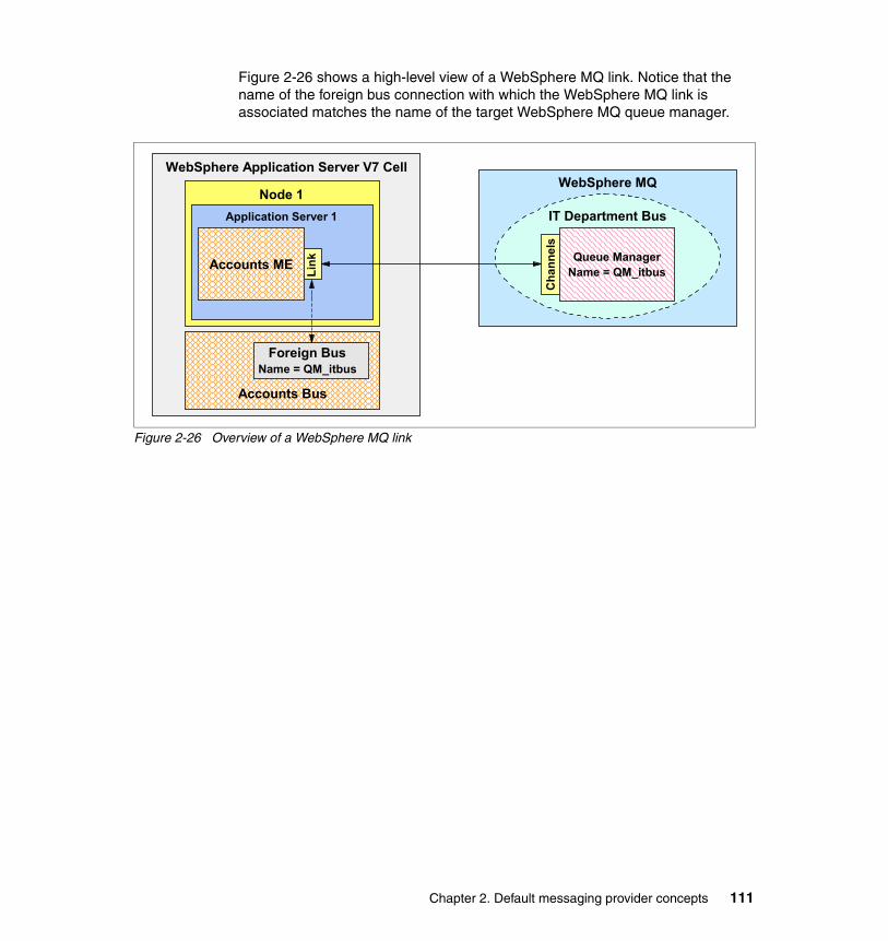
Figure 2-26 shows a high-level view of a WebSphere MQ link. Notice that the name of the foreign bus connection with which the WebSphere MQ link is associated matches the name of the target WebSphere MQ queue manager.
Figure 2-26 Overview of a WebSphere MQ link
WebSphere MQ
IT Department Bus
Cha
nnel
s
WebSphere Application Server V7 Cell
Node 1Application Server 1
LinkAccounts ME
Foreign BusName = QM_itbus
Accounts Bus
Queue ManagerName = QM_itbus
Chapter 2. Default messaging provider concepts 111
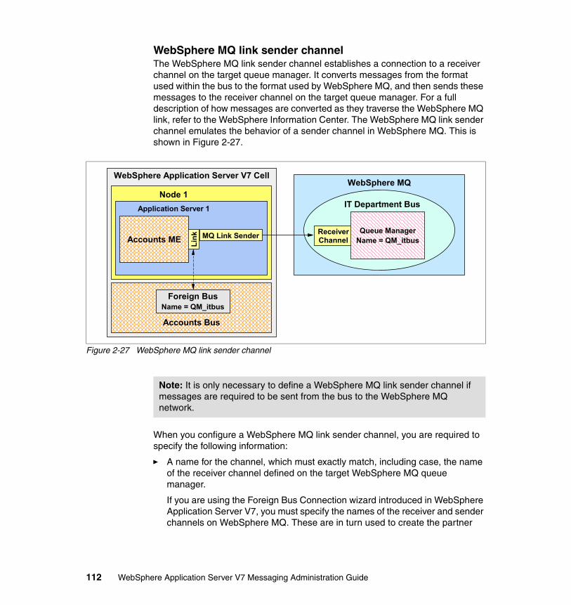
WebSphere MQ link sender channelThe WebSphere MQ link sender channel establishes a connection to a receiver channel on the target queue manager. It converts messages from the format used within the bus to the format used by WebSphere MQ, and then sends these messages to the receiver channel on the target queue manager. For a full description of how messages are converted as they traverse the WebSphere MQ link, refer to the WebSphere Information Center. The WebSphere MQ link sender channel emulates the behavior of a sender channel in WebSphere MQ. This is shown in Figure 2-27.
Figure 2-27 WebSphere MQ link sender channel
When you configure a WebSphere MQ link sender channel, you are required to specify the following information:
� A name for the channel, which must exactly match, including case, the name of the receiver channel defined on the target WebSphere MQ queue manager.
If you are using the Foreign Bus Connection wizard introduced in WebSphere Application Server V7, you must specify the names of the receiver and sender channels on WebSphere MQ. These are in turn used to create the partner
WebSphere MQ
IT Department Bus
ReceiverChannel
WebSphere Application Server V7 Cell
Node 1Application Server 1
LinkAccounts ME
Foreign BusName = QM_itbus
Accounts Bus
MQ Link Sender Queue ManagerName = QM_itbus
Note: It is only necessary to define a WebSphere MQ link sender channel if messages are required to be sent from the bus to the WebSphere MQ network.
112 WebSphere Application Server V7 Messaging Administration Guide

WebSphere MQ link sender and WebSphere MQ link receiver channels, respectively.
� The host name or IP address of the machine hosting the target queue manager
� The port number on which the target queue manager is listening for inbound communication requests
� An outbound transport chain
WebSphere MQ link receiver channelThe WebSphere MQ link receiver channel allows a sender channel within a queue manager to establish a connection to a messaging engine within the bus. It converts messages from the format used within WebSphere MQ to the format used by the bus. For a full description of how messages are converted as they traverse the WebSphere MQ link, refer to the WebSphere Information Center. The WebSphere MQ link receiver channel emulates the behavior of a receiver channel in WebSphere MQ. This is shown in Figure 2-28.
Figure 2-28 WebSphere MQ link receiver channel
Note: If the receiver channel on the target queue manager accepts only SSL connections, you must associate the transport chain with a suitably compatible set of SSL credentials.
WebSphere MQ
IT Department Bus
WebSphere Application Server V7 Cell
Node 1Application Server 1
LinkAccounts ME
Foreign BusName = QM_itbus
Accounts Bus
MQ Link ReceiverSender
ChannelQueue Manager
Name = QM_itbus
Chapter 2. Default messaging provider concepts 113

When configuring a WebSphere MQ link receiver channel, the following information is required: a name for the channel, which must exactly match, including case, the name of the sender channel defined on the target queue manager. If you are using the Foreign Bus Connection wizard introduced in WebSphere Application Server V7, you must specify the names of the receiver and sender channels on WebSphere MQ. These are in turn used to create the partner WebSphere MQ link sender and WebSphere MQ link receiver channels, respectively.
The inbound transport chain with which the sender channel on the queue manager communicates is dependent on the configuration of the WebSphere MQ sender channel. The WebSphere MQ administrator should be consulted to ensure that the sender channel is configured appropriately. As discussed in “Inbound transport chains” on page 90, the InboundBasicMQLink transport chain defaults to listening on port 5558 for connections from WebSphere MQ, and the InboundSecureMQLink transport chain defaults to listening on port 5578 for connections from WebSphere MQ.
MQ Publish/Subscribe broker profileBy default, a WebSphere MQ link only flows messages across the link that is addressed to a queue destination on the WebSphere MQ network. To flow publication messages across the WebSphere MQ link, configure a publish/subscribe broker profile for the WebSphere MQ link. A publish/subscribe broker profile allows topic mappings to be defined. These topic mappings define the topic names for which publication messages will be flowed across the WebSphere MQ link. Refer to the WebSphere Information Center for more information about the publish/subscribe bridge and the definition of topic mappings within a publish/subscribe broker profile.
Addressing destinations across the WebSphere MQ linkThere are several issues that must be considered when addressing a message to a destination that will flow across a WebSphere MQ link. These issues exist because of the differences in naming structure between the bus and WebSphere MQ.
WebSphere MQ has a two-level addressing structure, as follows:
� Queue manager name� Queue name
Note: It is only necessary to define a WebSphere MQ link receiver channel if messages are required to be sent from the WebSphere MQ network to the bus.
114 WebSphere Application Server V7 Messaging Administration Guide

Each of these elements within WebSphere MQ is limited in length to 48 characters. Within the bus, a destination can be uniquely identified using the following elements:
� Service integration bus name� Destination name
The bus places no length restrictions on these elements.
The difference in the allowable lengths of the various naming elements causes problems when a messaging application running in one environment attempts to address a message to a destination defined in the other environment, across the WebSphere MQ link. These issues are discussed in the sections that follow.
WebSphere MQ to service integration bus addressingMessages that are sent from a WebSphere MQ application to a bus destination that has a name greater than 48 characters in length must have some means of using the shorter name used in WebSphere MQ to address the long name used in the bus.
The bus uses an alias destination to map between the shorter name used by WebSphere MQ and the longer name used by the bus. A WebSphere MQ application can address a message to an alias destination within a bus that is defined with a short name of less than 48 characters. The alias destination then maps this message onto the destination defined with a long name of greater than 48 characters.
Service integration bus to WebSphere MQ addressingAnother problem can happen when a messaging client is required to address a message to a queue defined on an arbitrary queue manager within the WebSphere MQ network. For example, when defining JMS destinations for use by JMS client applications, it is only possible to specify the name of the bus on which the target destination is defined and the name of the destination. If the destination exists within the WebSphere MQ network, the name of the foreign bus connection is specified as the bus name. However, if the target queue is not defined on the queue manager to which the WebSphere MQ link connects, additional information is required in order to address messages to the correct queue.
To solve this problem, when defining a JMS queue or an alias destination that represents a queue on a WebSphere MQ network, use a special format for the target queue name, of the form queue_name@queue manager_name. These destination names are only parsed by the WebSphere MQ link, which uses the information to determine which values to place in the target queue and queue manager fields of the message header.
Chapter 2. Default messaging provider concepts 115
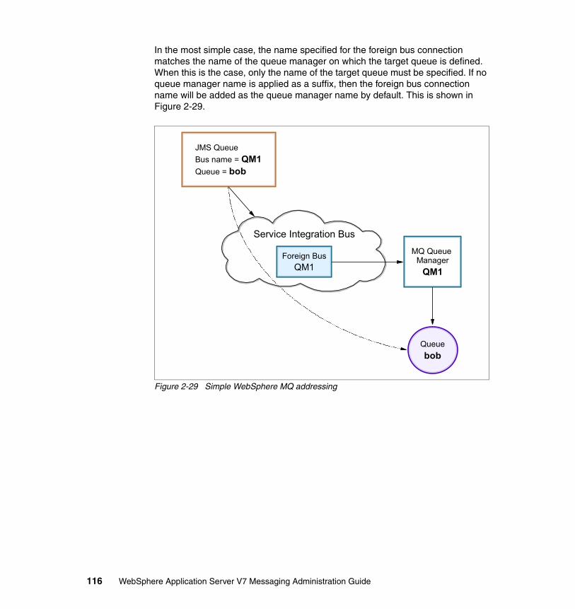
In the most simple case, the name specified for the foreign bus connection matches the name of the queue manager on which the target queue is defined. When this is the case, only the name of the target queue must be specified. If no queue manager name is applied as a suffix, then the foreign bus connection name will be added as the queue manager name by default. This is shown in Figure 2-29.
Figure 2-29 Simple WebSphere MQ addressing
Queuebob
Service Integration Bus
MQ Queue Manager
QM1
Foreign BusQM1
JMS QueueBus name = QM1Queue = bob
116 WebSphere Application Server V7 Messaging Administration Guide
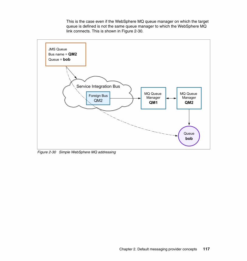
This is the case even if the WebSphere MQ queue manager on which the target queue is defined is not the same queue manager to which the WebSphere MQ link connects. This is shown in Figure 2-30.
Figure 2-30 Simple WebSphere MQ addressing
Queuebob
Service Integration Bus
MQ Queue Manager
QM1
Foreign BusQM2
MQ Queue Manager
QM2
JMS QueueBus name = QM2Queue = bob
Chapter 2. Default messaging provider concepts 117

When the name specified for the foreign bus connection does not match the name of the queue manager on which the target queue is defined, the queue manager name must be included as part of the queue name using the format described previously. This allows the message to be appropriately routed by WebSphere MQ once the message has left the bus. This is shown in Figure 2-31.
Figure 2-31 Advanced WebSphere MQ addressing
Queuebob
Service Integration Bus
MQ Queue Manager
QM1
Foreign BusFred
JMS QueueBus name = FredQueue = bob@QM1
118 WebSphere Application Server V7 Messaging Administration Guide

This mechanism enables a messaging client to address a message to a queue that is defined on any queue manager within the WebSphere MQ network. This is shown in Figure 2-32.
Figure 2-32 Advanced WebSphere MQ addressing
WebSphere MQ client linksA WebSphere MQ client link enables a messaging engine to act as a WebSphere Application Server V5.x embedded JMS Server. This function is provided as an aid to the migration of V5.x to V7 and should not be used for any other purpose.
A WebSphere MQ client link enables any applications that are installed and configured on V5.x, using V5.x JMS resources, to continue to function as normal after the V5.x JMS server has been migrated to V7.
Queuebob
Service Integration Bus
MQ Queue Manager
QM1
Foreign BusQM1
MQ Queue Manager
QM2
JMS QueueBus name = QM1Queue = bob@QM2
Note: The naming mechanism described within this section can only be used to address messages to destinations defined within WebSphere MQ. It must not be used to attempt to address messages to destinations defined on another bus. An indirect foreign bus connection must be used for that purpose.
Chapter 2. Default messaging provider concepts 119

The process of migrating a V5.x node that contains an embedded JMS server will remove that JMS server and create a bus with a WebSphere MQ client link. Queues previously defined on the V5.x embedded JMS server will be created automatically on the bus.
See the Information Center topic “Migrating from version 5 embedded messaging” for more information.
You should not need to create a WebSphere MQ client link manually. Use the one created automatically for you by the migration process.
2.2.7 WebSphere MQ servers
An alternative to using an WebSphere MQ link when connecting to WebSphere MQ is the use of a server called a WebSphere MQ server. A WebSphere MQ server provides a direct client connection between a service integration bus and queues on a queue manager, or for WebSphere MQ on z/OS, a queue sharing group.
WebSphere MQ for z/OS provides support for queue sharing groups. A queue sharing group is a collection of queues that can be accessed by one or more queue managers. Each queue manager that is a member of the queue sharing group has access to any of the shared queues. This has the advantages of high availability and workload balancing, as queue managers can fail over to one
Important: We recommend that you replace all V5.x JMS resources with v7 default messaging provider JMS resources as soon as possible. Once all resources have been changed, it is possible to delete the WebSphere MQ client link, as all applications will be using the V7 default messaging provider directly.
Enhanced in V7: For those who wish to access WebSphere MQ on a z/OS® platform, a mechanism called WebSphere MQ Server was introduced in WebSphere Application Server V6.1 that allows applications to take advantage of the high availability and load balancing features of the MQ queue sharing groups that the z/OS implementation of MQ provides. This has been extended to the distributed platforms that have WebSphere MQ V7 queue managers.
Note: The version of WebSphere MQ must be WebSphere MQ for z/OS Version 6 or later or WebSphere MQ Version 7 or later for distributed platforms.
120 WebSphere Application Server V7 Messaging Administration Guide

another as they become too busy or unavailable. For more information about MQ queue sharing groups refer to WebSphere MQ in a z/OS Parallel Sysplex Environment, SG24-6864.
Figure 2-33 shows a high-level overview of a WebSphere MQ server. It shows the high level of failure tolerance built in to this connectivity mechanism. An application can use any messaging engine within a bus to connect to the WebSphere MQ server, so if one fails another can be used. The WebSphere MQ server itself can connect to a single MQ queue manager, or one of a shared group (on z/OS) to access the queues. When connecting to a shared group, if one queue manager fails, another can be used to access the same queues.
Figure 2-33 Overview of a WebSphere MQ Server
For each queue manager or queue sharing group that must be accessed, a separate WebSphere MQ server definition is required to be created. The process of creating a server definition allows the connection details and any security information to be defined for the target queue manager or shared group.
The WebSphere MQ server is added to a bus as a bus member. Queue destinations can then be created for the server definition and the queue points assigned to individual MQ queues. The destinations can be internally or externally mediated (MQ link does not support this).
To the WebSphere MQ Server, the MQ queue manager or queue sharing group is regarded as a mechanism to queue messages for the bus. The WebSphere MQ Server is regarded by the WebSphere MQ network as just another MQ client attaching to the queue manager or queue sharing group.
One major difference between WebSphere MQ Server and WebSphere MQ link is that messages are not stored within the messaging engine with WebSphere MQ Server. Messaging applications directly send and receive messages from the
WebSphere MQ
Queue SharingGroup
WebSphere Application Server V7 Cell
Application ServerService Integration Bus
ME 1 QM1
QM2
QM3
ME 2
Application WebSphere MQ Server
Chapter 2. Default messaging provider concepts 121

WebSphere MQ queues. This is the reason that MQ server is tolerant of a message engine failure. The message engines are stateless in this regard.
Message beans can be configured to immediately process messages as they arrive on an MQ queue. Similarly, any bus mediations take place immediately upon a message appearing on an MQ queue.
Use WebSphere MQ server to exploit the availability and load balancing advantages of shared queues on a WebSphere MQ for z/OS network, and to support additional interfaces for integrating applications that are located inside and outside the enterprise.
See the following Information Center article for details about the advantages of WebSphere MQ Server over a WebSphere MQ link:
http://publib.boulder.ibm.com/infocenter/wasinfo/v7r0/index.jsp?topic=/com.ibm.websphere.pmc.express.doc/concepts/cjfp0012_.html
2.3 Service integration bus topologies
The following topologies are some of the typical ones implemented by the WebSphere Application Server default messaging provider (in increasing complexity) using the previously defined concepts. Many scenarios only require relatively simple bus topologies, perhaps even just a single server. When integrating applications that have been deployed to multiple servers, it is often appropriate to add those servers as members of the same bus. However, servers do not have to be bus members to connect to a bus.
122 WebSphere Application Server V7 Messaging Administration Guide
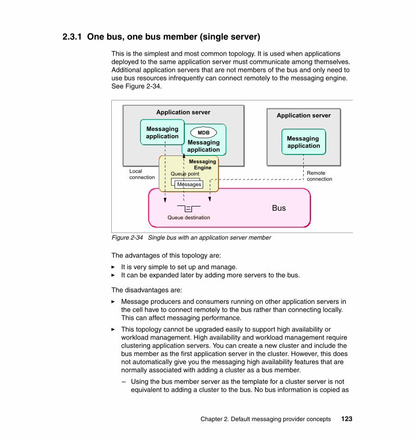
2.3.1 One bus, one bus member (single server)
This is the simplest and most common topology. It is used when applications deployed to the same application server must communicate among themselves. Additional application servers that are not members of the bus and only need to use bus resources infrequently can connect remotely to the messaging engine. See Figure 2-34.
Figure 2-34 Single bus with an application server member
The advantages of this topology are:
� It is very simple to set up and manage.� It can be expanded later by adding more servers to the bus.
The disadvantages are:
� Message producers and consumers running on other application servers in the cell have to connect remotely to the bus rather than connecting locally. This can affect messaging performance.
� This topology cannot be upgraded easily to support high availability or workload management. High availability and workload management require clustering application servers. You can create a new cluster and include the bus member as the first application server in the cluster. However, this does not automatically give you the messaging high availability features that are normally associated with adding a cluster as a bus member.
– Using the bus member server as the template for a cluster server is not equivalent to adding a cluster to the bus. No bus information is copied as
Bus
Application server
Queue destination
Application server
Remote connection
Messaging application
MDBMessaging application
Messaging application
Local connection
Messaging Engine
Queue point
Messages
Chapter 2. Default messaging provider concepts 123

part of the template process. The SIB service will be enabled on the new cluster server as a server property, not part of any particular bus.
– Using the bus member as the first server in the cluster server is not equivalent to adding a cluster to the bus. Only the original server is part of the bus.
It is possible to add a cluster to the bus, delete all of the queues that you want to be highly available or workload-managed, and recreate queues of the same name that have their queue points located on the new cluster bus member. Any messages on the queues are lost when they are deleted.
2.3.2 One bus, one bus member (a cluster)
With this variation, the bus member is a cluster. The messaging engine runs on one application server. If that server fails, the messaging engine executes on another application server in the cluster. This provides failover, but no workload management.
The server with the active messaging engine has local access to the bus, but the rest of the servers in the cluster access the bus remotely by connecting to the active messaging engine. Servers accessing the bus remotely can consume asynchronous messages from the remote messaging engine.
Message-driven beansFor message-driven bean applications connecting to a cluster bus member, you can use the Always activate MDBs in all servers setting in the activation specification to determine how messages are handled:
� All servers in the cluster can receive messages from the MDB application, to make full use of the processing power in the cluster.
� Just one server at a time can receive messages from the MDB application, to ensure sequential processing of the messages.
124 WebSphere Application Server V7 Messaging Administration Guide

FailoverIn this topology, when the application server that is running the messaging engine fails, the messaging engine is activated on another server in the cluster. In Figure 2-34 on page 123, the left side shows normal operation. The messaging applications are deployed and active on all application servers. The messaging engine is active on one of the servers. Applications on other servers connect to the messaging engine remotely.
Figure 2-35 Single bus with a cluster member: High availability
The right side of Figure 2-34 on page 123 shows what happens when one application server fails. The messaging application is still available on the remaining application servers and the messaging engine is activated on one of the remaining servers.
In this failover topology, all message processing is tunnelled through one messaging engine, so performance might be an issue.
When you add a server cluster to a bus, you can control which servers the messaging engine can run on, and the behavior of the messaging engine if a server is unavailable. Configuring preferred servers in a cluster for the messaging engine must be explicitly configured and could circumvent the high-availability advantages of the configuration if not done correctly.
BusQueue destination
Application server Application server
Cluster
Bus
Messaging application
Application server
Messaging application
Application server
Cluster
XQueue destination
Messaging Engine
Queue point
Messages
Messaging EngineQueue point
Messages
Messaging application
Messaging application
Tip: Be aware that some configurations of preferred servers for a messaging engine can make that messaging engine not highly available. If all the preferred servers are down, then a messaging engine will not be able to start even if there are other servers available in the cluster.
Chapter 2. Default messaging provider concepts 125

Workload managementYou can expand the failover topology so that each server in the cluster has an active messaging engine, thus providing workload management as well as failover (Figure 2-34 on page 123). Note that if one server goes down, the messaging engine will be activated on another server along with the messaging engine that was already running on the server, leaving both active on one server.
Figure 2-36 Single bus with a cluster member: Workload management
When a queue destination is assigned to the cluster, the queue is partitioned across the messaging engines in the cluster, with each messaging engine owning a partition of the queue. A message sent to the queue will be assigned to one partition. The messaging engine that owns the partition is responsible for managing the message. This means that requests sent to a destination can be served on any of the messaging engines running on any of the servers in the cluster.
BusQueue destination
Application server Application server
Cluster
Messaging Engine
Queue point
Messages
Messaging Engine
Queue point
Messages
Messaging application
Messaging application
126 WebSphere Application Server V7 Messaging Administration Guide
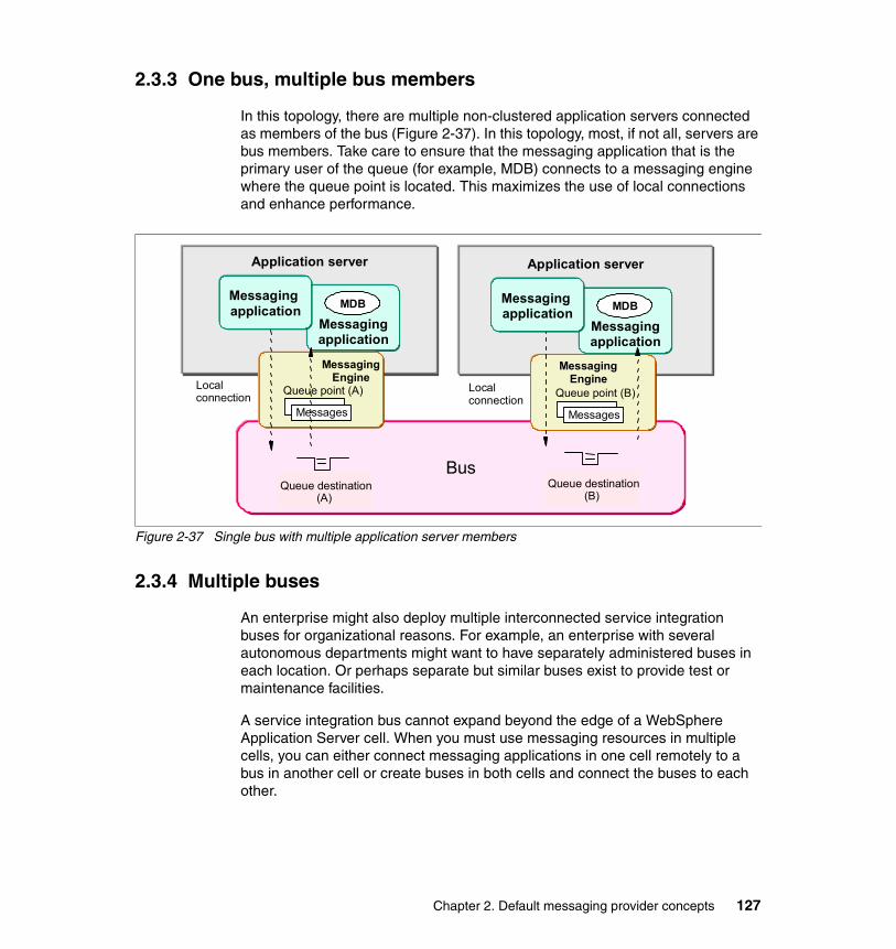
2.3.3 One bus, multiple bus members
In this topology, there are multiple non-clustered application servers connected as members of the bus (Figure 2-37). In this topology, most, if not all, servers are bus members. Take care to ensure that the messaging application that is the primary user of the queue (for example, MDB) connects to a messaging engine where the queue point is located. This maximizes the use of local connections and enhance performance.
Figure 2-37 Single bus with multiple application server members
2.3.4 Multiple buses
An enterprise might also deploy multiple interconnected service integration buses for organizational reasons. For example, an enterprise with several autonomous departments might want to have separately administered buses in each location. Or perhaps separate but similar buses exist to provide test or maintenance facilities.
A service integration bus cannot expand beyond the edge of a WebSphere Application Server cell. When you must use messaging resources in multiple cells, you can either connect messaging applications in one cell remotely to a bus in another cell or create buses in both cells and connect the buses to each other.
Bus
Application server
Queue destination (A)
Messaging application
MDB
Local connection
Messaging Engine
Queue point (A)
Messages
Application server
Messaging application
MDB
Local connection
Messaging Engine
Queue point (B)
Messages
Queue destination (B)
Messaging application
Messaging application
Chapter 2. Default messaging provider concepts 127

If you use messaging resources in a WebSphere MQ network, you can connect the service integration bus to the WebSphere MQ network, where it appears to be another queue manager. This is achieved through the user of an MQ link.
Figure 2-38 illustrates how a service integration bus can be connected to another service integration bus and to a WebSphere MQ network.
Figure 2-38 Multiple bus scenario
In the case of the connection between the two service integration buses, each messaging engine contains a service integration bus link configuration that defines the location of the messaging engine on the remote bus.
For the WebSphere MQ connection, the messaging engine contains an MQ link configuration that defines the queue manager on WebSphere MQ and identifies a queue manager name that it will be known by from the view of the WebSphere MQ network.
When an application sends a message to a queue on the remote bus, it can send it to an alias destination defined on the local bus that points to the queue destination on the second bus.
Application server
Bus
Application server
Messaging Engine
WebSphere MQ
QMGR
MQ client
Queue
Foreign bus
Application server
Messaging Engine
Bus
Foreign bus
Queue destination
Messaging Engine
Foreign bus
Alias destination
MQ LinkBus Link
Bus Link
Alias destination
Messaging application
Messaging application
128 WebSphere Application Server V7 Messaging Administration Guide
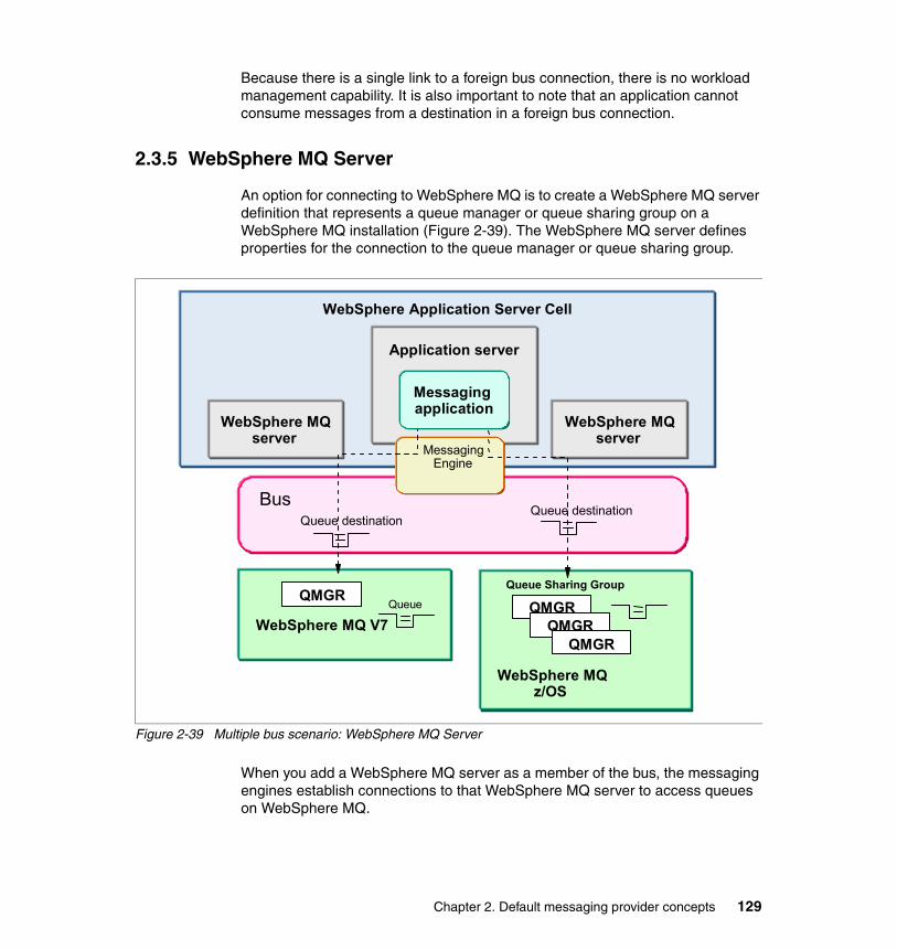
Because there is a single link to a foreign bus connection, there is no workload management capability. It is also important to note that an application cannot consume messages from a destination in a foreign bus connection.
2.3.5 WebSphere MQ Server
An option for connecting to WebSphere MQ is to create a WebSphere MQ server definition that represents a queue manager or queue sharing group on a WebSphere MQ installation (Figure 2-39). The WebSphere MQ server defines properties for the connection to the queue manager or queue sharing group.
Figure 2-39 Multiple bus scenario: WebSphere MQ Server
When you add a WebSphere MQ server as a member of the bus, the messaging engines establish connections to that WebSphere MQ server to access queues on WebSphere MQ.
Bus
Application server
WebSphere MQ V7
QMGRQueue
WebSphere MQ server
WebSphere Application Server Cell
Messaging Engine
WebSphere MQ server
WebSphere MQ z/OS
Queue Sharing Group
QMGRQMGR
QMGR
Queue destinationQueue destination
Messaging application
Chapter 2. Default messaging provider concepts 129
To the WebSphere MQ server, the MQ queue manager or queue sharing group is regarded as a mechanism to queue messages for the bus. The WebSphere MQ server is regarded by the WebSphere MQ network as just another MQ client attaching to the queue manager or queue sharing group.
WebSphere MQ server provides the following advantages over a WebSphere MQ link:
� WebSphere MQ server allows applications to exploit the higher availability and optimum load balancing provided by WebSphere MQ on z/OS.
� With WebSphere MQ link, messages from WebSphere MQ are delivered to a queue destination in the bus. When a messaging engine fails, messages at destinations in the messaging engine cannot be accessed until that messaging engine restarts. When you use a WebSphere MQ server that represents a queue sharing group, the bus can continue to access messages on the shared queue even when a queue manager in the queue sharing group fails. This is because the bus can connect to a different queue manager in the queue sharing group to access the same shared queues.
� Messages are not stored within the messaging engine. Messaging applications directly send and receive messages from the queues in WebSphere MQ, making the WebSphere MQ server tolerant of a messaging engine failure. This allows message beans to be configured to immediately process messages as they arrive on an MQ queue. Similarly, any bus mediations take place immediately upon a message appearing on an MQ queue.
� With WebSphere MQ link, applications must push messages from the WebSphere MQ network end of the link. With WebSphere MQ server, applications can pull messages from the WebSphere MQ network. WebSphere MQ server, therefore, provides a better proposition than WebSphere MQ link in situations requiring optimum load balancing.
2.4 High availability and workload management
High availability and workload management can be achieved using clusters as bus members.
2.4.1 Cluster bus members for high availability
When you add a cluster to a bus, a single messaging engine is created. The messaging engine is active on only one server within the cluster. In the event of an application server or messaging engine failure, the messaging engine becomes active on another server in the cluster if one is available.
130 WebSphere Application Server V7 Messaging Administration Guide

By default, the messaging engine starts on the first available server in a cluster. If you want to ensure that the messaging engine runs only particular servers within the cluster, then you must configure this. See 3.4.6, “Manually creating messaging engine policies” on page 177, for details about configuring preferred servers.
2.4.2 Cluster bus members for workload management
Because a single messaging engine for the cluster is active, there is no workload management by default. To achieve greater throughput of messages, it is beneficial to spread messaging load across multiple servers and, optionally, across multiple hosts. You can achieve this while maintaining a simple destination model by creating additional messaging engines for the cluster, each of which has a preference to run on a specific server in the cluster.
This enables a messaging engine to run in every server in the cluster, thus providing every application with access to a local messaging engine. Local access is always better for messaging performance, especially in the case of queues, where the queue is assigned to the bus member from which it is being accessed.
When a queue is assigned to a cluster bus member, the queue will be partitioned across all messaging engines in the cluster.
2.4.3 Partitioned queues
A queue is partitioned automatically for you when a queue destination is assigned to a cluster bus member. Every messaging engine within the cluster owns a partition of that queue and is responsible for managing messages assigned to the partition. Every message sent to the queue is assigned to exactly one of the partitions.
Local partitionsWhen a JMS client attempting to access a partitioned queue is connected to a messaging engine hosting one of those partitions (a messaging engine in the cluster), then the client is able to access only that local partition of the queue for both consuming and producing messages
The only instance where messages are not sent to the local partition is when that local partition is full and other partitions of the queue are not. In this case, messages are routed to an available remote partition.
Chapter 2. Default messaging provider concepts 131

Clients attempt to consume only from the local partition, even if there are no messages on the local partition and there are messages available on other partitions.
Remote partitionsWhen a JMS client connects to a messaging engine that is not a host for the destination partition (a messaging engine in the same bus but not in the cluster), each client-created consumer connects to one remote partition to consume messages. Each session created is workload managed with respect to the remote partition to which it connects.
Messages sent to a remote partitioned destination are workload-managed across the individual partitions on an individual message basis, regardless of the session.
Cluster bus members and partitioned queues alone do not give better message throughput. The applications producing and consuming the messages must be configured to use the bus.
See the following sections at the information center for details:
� Workload sharing with queue destinations
http://publib.boulder.ibm.com/infocenter/wasinfo/v7r0/index.jsp?topic=/com.ibm.websphere.pmc.nd.multiplatform.doc/concepts/cjt0014_.html
� Performing request/reply JMS messaging with a scalable bus member
http://publib.boulder.ibm.com/infocenter/wasinfo/v7r0/index.jsp?topic=/com.ibm.websphere.pmc.nd.multiplatform.doc/concepts/cjt0020_.html
� How a message-driven bean connects in a cluster
http://publib.boulder.ibm.com/infocenter/wasinfo/v7r0/index.jsp?topic=/com.ibm.websphere.pmc.nd.iseries.doc/concepts/cjn_mdb_endpt_overview.html
2.4.4 JMS clients connecting to a cluster of messaging engines
JMS clients outside of a cluster can connect directly into a workload-managed cluster of messaging engines. In this case, workload-managed means that the cluster is a bus member and one messaging engine has been added for every server in the cluster. Each messaging engine has been configured to prefer a different server in the cluster. JMS clients connect to the messaging engines using the rules described in 2.6, “Connecting to a service integration bus” on page 140.
132 WebSphere Application Server V7 Messaging Administration Guide

In this scenario, there is an undesirable side effect of the rules when the servers in the cluster are used as the provider endpoints for the connection factory. Consider the following example: A JMS client connects to a cluster of servers (A, B, and C). The connection factory is configured with provider endpoints of A, B, and C. This allows the client to bootstrap to any of the three servers in the cluster. Following the connection rules, the connection factory bootstraps to the first server in the provider endpoints list, A. Server A has a local messaging engine. Therefore, the messaging engine on server A is chosen as the preferred connection point for the client.
Because the connection always tries the first entry in the provider endpoints list first, every client connecting directly into the cluster connects to the messaging engine in server A. All messages produced for a destination partitioned across the cluster are assigned to the partition of the destination associated with the messaging engine. This is not very good for workload management of messages. There are two methods that can overcome this:
� Enable a SIB service on a server outside of the cluster. Configure the provider endpoints on the connection factory to point to this SIB service. If there is no messaging engine local to this SIB service, then the client connections will be workload-managed around all of the messaging engines in the bus.
If you only have messaging engines in the cluster, no further configuration is required. If there are other non-cluster bus members, and you only want the clients to connect directly to the messaging engines in the cluster, then you must configure a target group on your connection factory.
� Provide different clients with differently configured connection factories, each of which has a different provider endpoint in the first position in the list.
2.4.5 Preferred servers and core group policies
To configure a messaging engine to prefer a server or group of servers, you must configure a core group policy. A core group policy is used to identify server components and define how they will behave within a cell or cluster. This section discusses these components. See 3.4.4, “Adding a cluster as a bus member” on page 171, for details on how these can be set using the new wizard.
Policy typeFor messaging engines, use a policy type of One of N. This means that, while the messaging engine can be defined on every server in the cluster, WebSphere’s HA Manager ensures that it is only active on one of the servers in the group, and will always be active on one of the servers, if one is available.
Chapter 2. Default messaging provider concepts 133

Match criteriaThe match criteria of a core group policy enables the HA Manager to decide what server components match the policy and so should be managed according to the policy. There are two match criteria that you must use to match a messaging engine:
� type=WSAF_SIB
This criterion matches any messaging engine.
� WSAF_SIB_MESSAGING_ENGINE=messaging_engine_name
This criterion matches the messaging engine of the name provided.
Preferred serversThe preferred servers defined in a policy allow you to list a group of servers on which the messaging engine will prefer to run. The higher up in the list of preferred servers that a particular server is, the more preferred it is. For a messaging engine that is part of a cluster bus member, select only preferred servers that are part of the cluster. The messaging engines are defined only in the cluster and cannot be run on any servers outside of the cluster.
Fail back and preferred servers onlyThese two options have a large effect on how a particular policy will make a messaging engine behave in a cluster.
If you select Fail back, when a more preferred server becomes available, the messaging engine will be deactivated where it currently runs and activated on the more preferred server. Enabling fail back ensures that a messaging engine will always run on the most preferred server that is available. This is usually desirable, as there should be a good reason for configuring a preferred server in the first place. If you do not enable fail back, then once a messaging engine has started it will not move to a more preferred server if one becomes available.
If you select Preferred servers only, then the messaging engine will only be allowed to be active on servers in the policy’s preferred servers list. If you do not select Preferred servers only, all servers in the cluster that are not in the list will be able to have the messaging engine active on them, but they will be selected only if none of the preferred servers are available.
Be very careful when selecting preferred servers only because it is possible to reduce or remove the high availability of a messaging engine and of the queue partitions that the messaging engine owns. If none of the preferred servers are available, then the messaging engine will not be active anywhere. This means that any queue partitions owned by that messaging engine will also be unavailable. Any messages currently on those partitions will be trapped and
134 WebSphere Application Server V7 Messaging Administration Guide

cannot be consumed until one of the preferred servers has become available and the messaging engine has been activated.
Large clustersIf you have a medium or large cluster of servers (five or more) configured with messaging engines, then we recommend a slightly special configuration of preferred servers.
With a large number of messaging engines defined on a cluster, it would be undesirable to have all of the messaging engines starting up on the first server in the cluster to start. We recommend the following configuration.
Configure each messaging engine with a group of preferred servers consisting of a subset of the cluster with fail back and preferred servers only enabled. The set of preferred servers should be large enough to support your availability requirements by providing sufficient failover capabilities for the messaging engine. For example, you might decide that the messaging engine must be able to run on two or three servers. Configure each messaging engine with a different subset of servers, with each messaging engine having a unique, most-preferred server, as in Figure 2-40. In Figure 2-40 the shading indicates the preferred order of the servers.
Figure 2-40 Configuring large clusters of messaging engines
Cluster
Server 1 Server 2 Server 3 Server 4 Server 5
Messaging Engine 000
Messaging Engine 001
Messaging Engine 002
MessagingEngine 003 Messaging Engine 003
Messaging Engine 004MessagingEngine 004
Chapter 2. Default messaging provider concepts 135

2.4.6 Best practices
For the greatest throughput of messages, do the following:
1. Create a cluster bus member with messaging engines running on every server in the cluster.
2. Define the queues being used on the cluster bus member.
3. Ensure that message production to the queue is workload-managed across the cluster:
a. Install an EJB or servlet application on the cluster and have that application produce the messages. Workload management of the client calls to the application will manage the workload of message production across the cluster.
b. Produce messages from clients connected to messaging engines outside of the cluster. The bus can then workload manage the messages across the cluster.
4. Install an MDB application on the cluster to consume the queue messages.
2.5 Service integration bus and message-driven beans
Message-driven beans attached to destinations in the bus are attached by means of the SIB JMS Resource Adapter, an activation specification, and a JMS destination. The resource adapter is responsible for connecting to the bus and delivering messages to the MDB.
2.5.1 Message-driven beans connecting to the bus
The resource adapter always attempts to connect a message-driven bean to a messaging engine in the same server if one is defined there. If there is no messaging engine in the same server, then a messaging engine is selected from the bus using the standard connection selection process (see 2.6, “Connecting to a service integration bus” on page 140).
There are three scenarios in which an MDB will start but not connect to the destination for which it is configured to listen. The resource adapter will allow the MDB application to start under these circumstances and will attempt to connect the MDB to its configured destination as soon as possible.
Note: For performance reasons, we recommend that MDBs are always connected to a messaging engine where the queue point exists.
136 WebSphere Application Server V7 Messaging Administration Guide

Local messaging engine defined but unavailableIf a messaging engine is defined locally, but is unavailable when the MDB application starts, the MDB application starts successfully and the resource adapter connects it to the messaging engine when it activates. Situations when this happens include:
� If the messaging engine has not started by the time the MDB application is started.
� The MDB is installed on a cluster bus member that has been configured for high availability, and is on a server other than the one with the active messaging engine.
When an MDB application is started, but the locally defined messaging engine is unavailable, the warning message in Example 2-1 appears in SystemOut.log.
Example 2-1 Message: Local messaging engine not available
CWSIV0759W: During activation of a message-driven bean, no suitable active messaging engines were found in the local server on the bus MyBus
When the messaging engine activates, the message in Example 2-2 is displayed when the MDB is connected to its destination.
Example 2-2 MDB connected to messaging engine
CWSIV0764I: A consumer has been created for a message-driven bean against destination MyQueue on bus MyBus following the activation of messaging engine cluster1.000-MyBus.
Note: Messaging engines are frequently the last component of an application server to complete their startup, often even after the open for e-business message is issued for the server. As a result, it is not unusual for MDB applications to cause the above warning message.
Chapter 2. Default messaging provider concepts 137

Remote destination unavailableIf there is an active locally defined messaging engine, but the MDB is configured to listen to a queue currently unavailable (for example, if the messaging engine that hosts the queue point is not active), then the warning message shown in Example 2-3 is displayed.
Example 2-3 Message: Remote destination unavailable
CWSIV0769W: The creation of a consumer for remote destination MyQueue on bus MyBus for endpoint activation ...<section removed>... failed with exception javax.resource.ResourceException: CWSIP0517E: Cannot attach to queue message point for destination MyQueue.
The resource adapter tries to connect the MDB to the configured destination every 30 seconds until it succeeds. Each failure to connect results in the message shown in Example 2-3.
Remote messaging engine unavailableIf there is no locally defined messaging engine, then a messaging engine is selected from the bus. If there are no currently available messaging engines in the bus, then the resource adapter allows the MDB application to start anyway and attempt to connect the MDB to a messaging engine every 30 seconds. The message shown in Example 2-4 appears on the first failed attempt to connect to a messaging engine. Subsequent failures are silent.
Example 2-4 Message: Remote messaging engine unavailable
CWSIV0775W: The creation of a connection for destination MyQueue on bus MyBus for endpoint activation ...<section removed>... failed with exception com.ibm.websphere.sib.exception.SIResourceException: CWSIT0019E: No suitable messaging engine is available in bus MyBus.
No messages are delivered to the MDB until the resource adapter has been able to start a connection to an active messaging engine. The message shown in Example 2-5 is displayed with a connection is made.
Example 2-5 Message: Connection made to remote messaging engine
CWSIV0777I: A connection to remote messaging engine myNode.server1-MyBus for destination MyQueue on bus MyBus for endpoint activation ...<section removed>... is successfully created.
138 WebSphere Application Server V7 Messaging Administration Guide

2.5.2 MDBs and clusters
The behavior of message-driven beans installed on clusters that use the bus is directly related to the bus configuration.
Clusters that are not part of a busWhen an MDB is installed on a cluster that is not part of a bus, the MDBs on each server connect independently to the bus to consume messages.
Clusters configured for highly available messagingWhen a cluster is configured for highly available messaging, a messaging engine is active on one of the servers in the cluster. An MDB application installed on that cluster will start on all servers in the cluster, but only the MDB on the server with the active messaging engine will receive messages. Should the active messaging engine fail, or the server on which it is active fail or be stopped, then the messaging engine will start on another server in the cluster. The MDB on that server will be connected to the messaging engine and start receiving messages.
In this scenario, the bus has been configured to have one active messaging engine in the cluster, and, effectively, the MDB mirrors that configuration.
Clusters configured for messaging workload managementWhen a cluster is configured for messaging workload management, a messaging engine will most likely be active on each server in the cluster.
For an MDB installed on the cluster and listening to a topic with a non-durable subscription, each message on the topic will be received once on each server with an active messaging engine. If more than one messaging engine is active on a server, the message will be received only once by the MDB on that server.
If the MDB installed on the cluster is listening to a topic with a shared, durable subscription, then one MDB in the cluster receives each message published on the topic only once.
If the MDB installed on the cluster is listening to a queue partitioned on the cluster, then the MDB is attached to each partition active on the server. Should
Note: You should not configure an MDB on a cluster with no local messaging engine to listen to a partitioned queue in another cluster. There is no guarantee that every partition of the queue in the other cluster will have at least one MDB listening to it. This could lead to a partition without any consumers.
Chapter 2. Default messaging provider concepts 139

more than one messaging engine be active on a server, then the MDB will receive messages from each messaging engine’s partition of the queue.
For an MDB installed on the cluster and listening to a queue with its queue point on a messaging engine outside of the cluster, the MDB on each server is attached to the queue. An MDB on a server with more than one active messaging engine will not receive a greater proportion of the messages than an MDB on a server with only a single active messaging engine.
2.6 Connecting to a service integration busA JMS client obtains connections to a service integration bus using a suitably configured JMS connection factory defined for the default messaging provider. However, the selection of which messaging engine within a particular service integration bus that a JMS client will connect to depends on the connection properties defined within the JMS connection factory. The options available can range from simply connecting to any suitable messaging engine within the named service integration bus to using a highly specific connection selection algorithm. The sections that follow describe the mechanisms used to determine the most suitable messaging engine when a JMS client is connecting to a service integration bus.
2.6.1 JMS client run time environmentRegardless of the environment on which a JMS client is executing, it always performs the same steps in order to connect to a JMS provider. These steps are:
1. Obtain a reference to a JMS connection factory from the JNDI name space.2. Invoke the createConnection method on the JMS connection factory.
The important point here is that the JMS connection factory object will always execute within the same process as the JMS client. However, the JMS client, and
Note: New in V7: A new option on an activation spec called “Always activate MDBs in all servers” has been added that, when enabled, will cause all MDBs in the cluster to receive messages.
Note: None of the messaging engine selection processes discussed in this section affect the JMS client in any way. As far as the JMS client is concerned, the ConnectionFactory simply returns a connection to the underlying messaging provider, in this case, a service integration bus. The process of configuring a ConnectionFactory in order to tailor the messaging engine that is selected is a purely administrative task.
140 WebSphere Application Server V7 Messaging Administration Guide

therefore the JMS connection factory, might be executing inside of a WebSphere process, or they might be executing within a stand-alone JVM™. In the case of the connection factory for the default messaging provider, the behavior of the connection factory depends on the environment in which it is executing:
� Clients running inside of WebSphere Application Server
When the connection factory is executing within the WebSphere Application Server environment, it is able to communicate with components of the WebSphere run time in order to determine which messaging engines are defined within the specified service integration bus, and where these messaging engines are currently located. The relevant connection properties configured on the connection factory can then be used to select a suitable messaging engine to which to connect.
� Clients running outside of WebSphere Application Server
When the connection factory is executing outside of the WebSphere Application Server environment, or in a WebSphere Application Server environment on a different cell to the target bus, it is not able to determine which messaging engines are defined within the specified service integration bus or where they are currently located. In order to obtain this information, the connection factory must connect to an application server within the same cell as the target bus. This application server is known as a bootstrap server.
Note: The connection factory is only able to determine the location of messaging engines that are defined within the same WebSphere cell. If the target bus is defined within another cell, then a list of suitable provider endpoints must be configured on the connection factory.
Chapter 2. Default messaging provider concepts 141

A bootstrap server is simply an ordinary application server that is running the SIB service. The SIB service is the component within an application server that manages the service integration bus resources for that application server. It is the SIB service that enables an application server to act as a bootstrap server for default messaging provider connection factories. However, while the bootstrap server must be running the SIB service, it does not necessarily need to be hosting any messaging engines. This is shown in Figure 2-41.
Figure 2-41 Using a bootstrap server with a messaging engine
Use the provider endpoints property to configure the bootstrap servers to which a connection factory can connect.
Provider endpointsThe provider endpoints property of the connection factory allows an administrator to specify a comma-separated list of suitable bootstrap servers for the connection factory. Each bootstrap server in the list is specified as a triplet of the form:
hostname : port : transport chain
WebSphere Application Server V6 Cell
SIB_ENDPOINT_ADDRESS
Application Server
SIB Service
SIB_ENDPOINT_ADDRESS
Application Server
MessagingEngine
SIB Service
J2EE Client Container
JMS Client
1. Bootstrap 2. Connect
142 WebSphere Application Server V7 Messaging Administration Guide

The different elements are:
� hostname is the name of the host on which the bootstrap server is running. If a host name is not specified, the value defaults to localhost.
� port is the port number on which the SIB service for the bootstrap server is listening. This can be determined from the relevant messaging engine inbound transport that will be used for the bootstrap request. If no port is specified, the value defaults to 7276 (the default port number for SIB_ENDPOINT_ADDRESS).
� transport chain specifies the transport chain that will be used to send the bootstrap request to the bootstrap server. Valid values for transport chain are:
– BootstrapBasicMessaging
The bootstrap request will be sent to the bootstrap server using a standard TCP/IP connection to the InboundBasicMessaging transport chain.
– BootstrapSecureMessaging
The bootstrap request will be sent to the bootstrap server over a secure TCP/IP connection to the InboundSecureMessaging transport chain.
– BootstrapTunneledMessaging
The bootstrap request will be tunneled to the bootstrap server over an HTTP connection. Before you can use this transport chain, you must define a corresponding transport chain on the bootstrap server.
– BootstrapTunneledSecureMessaging
The bootstrap request will be tunneled to the bootstrap server over a secure HTTP connection. Before you can use this transport chain, you must define a corresponding transport chain on the bootstrap server.
If no transport chain is specified the value defaults to BootstrapBasicMessaging.
If no value is specified for the provider endpoint property, the connection factory uses the following default provider endpoint address:
localhost:7276:BootstrapBasicMessaging
Dedicated bootstrap serversBecause the location of a bootstrap server is defined explicitly within the provider endpoints property of a connection factory, consideration must be given to the availability of the bootstrap server. By specifying a list of bootstrap servers in the provider endpoints property, a connection factory is able to transparently bootstrap to another server in the list in the event that one of the bootstrap servers fails. The connection factory attempts to connect to a bootstrap server in the order in which they are specified in the provider endpoints list. However, you
Chapter 2. Default messaging provider concepts 143

should avoid specifying a long list of bootstrap servers. Consider configuring only a few highly available application servers as dedicated bootstrap servers.
2.6.2 Controlling messaging engine selection
The remaining connection properties that can be specified on a connection factory for the default messaging provider are used to control how the connection factory selects the messaging engine to connect to on the specified service integration bus. The sections that follow discuss these properties in more detail.
Bus nameThe only connection property that is required when configuring a connection factory for the default messaging provider is the bus name property. The value of the bus name property specifies the name of the bus to which the connection factory will create JMS connections.
144 WebSphere Application Server V7 Messaging Administration Guide

In the absence of any other connection properties, the connection factory returns a connection to any available messaging engine in the bus. However, despite the freedom to connect to any available messaging engine in the bus, the connection factory applies a few simple rules to find the most suitable messaging engine with which to connect. The process is as follows:
1. The connection factory looks for a messaging engine within the specified service integration bus that is in the same server process as the JMS client. If a messaging engine within the specified bus is found in the same application server process, then a direct in-process connection is made from the JMS client to the messaging engine. This is shown in Figure 2-42.
Figure 2-42 In-process connection for a JMS client and a messaging engine
Note: A direct in-process connection usually provides the best performance when connecting a JMS client to a messaging engine. However, the location of the bus destinations with respect to the application can also affect performance. Therefore, connecting an application directly to a messaging engine that owns a destination may be preferable to connecting to a messaging engine in the same server.
WebSphere Application Server V6 Cell
Host 2
Server 3
MessagingEngine
Server 4
MessagingEngine
Host 1
Server 1
MessagingEngine
JMS Client
Server 2
MessagingEngine
Chapter 2. Default messaging provider concepts 145

2. If it is not possible for the connection factory to create a connection to a messaging engine in the same application server process, the connection factory looks for a messaging engine that is running on the same host as the JMS client. If a messaging engine within the specified bus is found on the same host, then a remote connection is made from the JMS client to the messaging engine. This is shown in Figure 2-43.
Figure 2-43 Remote connection on the same host
This same host preference only applies if the JMS application is running inside an application server. If the application is a stand-alone client then it could be connected to any messaging engine in the bus.
3. If it is not possible for the connection factory to create a connection to a messaging engine on the same host as the JMS client, the connection factory
Note: If multiple messaging engines are available on the same host as the JMS client, new connections to the target bus will be load-balanced across them.
WebSphere Application Server V6 Cell
Host 2
Server 3
MessagingEngine
Server 4
MessagingEngine
Host 1
Server 1
JMS Client
Server 2
MessagingEngine
146 WebSphere Application Server V7 Messaging Administration Guide

looks for any other messaging engine that is part of the specified service integration bus. This is shown in Figure 2-44.
Figure 2-44 Remote connection on a different host
4. If it is not possible for the connection factory to create a connection to any of the messaging engines that make up the specified service integration bus, the connection factory throws a javax.jms.JMSException to the JMS client. The javax.jms.JMSException contains a linked exception to a service integration bus specific exception, similar to that shown in Example 2-6.
Example 2-6 Failure to connect to a messaging engine
com.ibm.websphere.sib.exception.SIResourceException: CWSIT0019E: No suitable messaging engine is available in bus SamplesBus.
Note: If multiple messaging engines are available within the target bus, new connections to the target bus will be load balanced across them.
WebSphere Application Server V6 Cell
Host 2
Server 3 Server 4
MessagingEngine 4
Host 1
Server 1
JMS Client
Server 2
Chapter 2. Default messaging provider concepts 147

Target inbound transport chainThe target inbound transport chain property for a connection factory specifies the transport chain that the JMS client should use when establishing a remote connection to a messaging engine. Suitable values for this property are:
� InboundBasicMessaging
The JMS client establishes a standard TCP/IP connection to the messaging engine. This is the default value for the target inbound transport chain property.
� InboundSecureMessaging
The JMS client establishes a secure TCP/IP connection to the messaging engine.
The process of selecting a suitable messaging engine takes into account the inbound transport chains that are currently available to those messaging engines under consideration. There is no point in selecting a messaging engine that cannot be contacted using the target transport chain specified, so a final selection is made only from those messaging engines that have the specified target transport chain available to them.
Connection proximityThe messaging engine selection process performed by the connection factory can be subtly altered by specifying different connection proximities. The connection proximity property is used to restrict the set of available messaging engines considered for selection by the connection factory. The set of available messaging engines is restricted based on their proximity to the JMS client (when running in an application server) or the bootstrap server acting on behalf of the JMS client. The valid values for the connection proximity property are:
� Bus
The set of available messaging engines will include all messaging engines defined within the target service integration bus. This is the default value for the connection proximity property and, in effect, does not restrict the set of available messaging engines in any way. When a connection proximity of Bus is specified, the messaging engine selection process described in “Bus name” on page 144 is used.
� Cluster
The set of available messaging engines for the target service integration bus only includes those messaging engines defined within the same cluster as the JMS client or bootstrap server.
148 WebSphere Application Server V7 Messaging Administration Guide

� Host
The set of available messaging engines for the target service integration bus only includes those messaging engines running on the same host as the JMS client or bootstrap server.
� Server
The set of available messaging engines for the target service integration bus only includes those messaging engines running within the same application server process as the JMS client or bootstrap server.
To see how the value of the connection proximity property affects the messaging engine selection process, consider the configuration shown in Figure 2-45. All of the messaging engines shown in Figure 2-45 exist within the same service integration bus.
Figure 2-45 Sample topology for a service integration bus
WebSphere Application Server V6 Cell
Host 2
Server 3
MessagingEngine
Server 4
MessagingEngine
Host 1
Server 1
JMS Client
Cluster 1
Server 2
MessagingEngine
Cluster 2
Chapter 2. Default messaging provider concepts 149

The effect of the value of the connection proximity property on messaging engine selection is described in Table 2-6.
Table 2-6 Effect of connection proximity on messaging engine selection
Target groupsTarget groups provide a further means of controlling the selection of a suitable messaging engine by restricting the messaging engines available for consideration during the connection proximity check. Before the connection proximity search is performed, the set of messaging engines that are members of the specified target group is determined. The connection proximity check is then restricted to these messaging engines.
The use of target groups is controlled through the target, target type, and target significance properties of the connection factory, the descriptions for which are:
� Target
The target property identifies a group of messaging engines that should be used when determining the set of available messaging engines. If no target group is specified, then no sub-setting of the available messaging engines takes place and every messaging engine within the bus is considered during the connection proximity check. By default, no target group is specified.
Connection proximity value
Messaging engine selected
Bus The JMS client connects to the messaging engine on server 2, following the rules described in “Bus name” on page 144.
Cluster The JMS client connects to the messaging engine on server 3 because this is the only messaging engine in the same cluster as the client.
Host The JMS client connects to the messaging engine on server 2 because this is the only messaging engine on the same host as the client.
Server The JMS client fails to connect to the service integration bus because there is no messaging engine in the same server as the client.
150 WebSphere Application Server V7 Messaging Administration Guide

� Target type
The target type property specifies the type of the group identified by the target property. Valid values for the target type property are:
– Bus member name
Bus member name indicates that the target property specifies the name of a bus member. Because bus members can only be application servers or application server clusters, the value of the target property must be an application server name of the form <node name>.<server name> or the name of the cluster. This option applies to any messaging engine within that bus member.
– Custom messaging engine group name
This value indicates that the target property specifies the name of a user-defined custom group of messaging engines. A messaging engine is registered with a custom group by specifying the name of the group in the target groups property for the messaging engine. The registration of the messaging engine takes place when the messaging engine is started.
– Messaging engine name
Choosing this value indicates that the target property specifies the name of a specific messaging engine. This is the most restrictive target type that can be specified.
The value of the target property must be a messaging engine name, for example, <cluster name>.<nnn>-<bus name>.
� Target significance
The target significance property allows the connection factory to relax the rules that are applied regarding the target group. The valid values for this property are:
– Preferred
Use Preferred to indicate that a messaging engine be selected from the target group. A messaging engine in the target group is selected if one is available. If a messaging engine in the target group is not available, an available messaging engine within the specified service integration bus, but outside of the target group, is selected.
– Required
Use Required to indicate that a messaging engine be selected from the target group. A messaging engine in the target group is selected if one is available. If a messaging engine in the target group is not available, the connection process fails.
Chapter 2. Default messaging provider concepts 151

To see how the values of the target group properties affect the messaging engine selection process, consider the configuration shown in Figure 2-46. All of the messaging engines shown in Figure 2-46 exist in the same service integration bus.
Figure 2-46 Sample topology for a service integration bus
WebSphere Application Server V6 Cell
Host 2
Server 3
MessagingEngine 3
Server 4
MessagingEngine 4
Host 1
Server 1
MessagingEngine 1
JMS Client
Cluster 1
Server 2
MessagingEngine 2
Cluster 2
152 WebSphere Application Server V7 Messaging Administration Guide
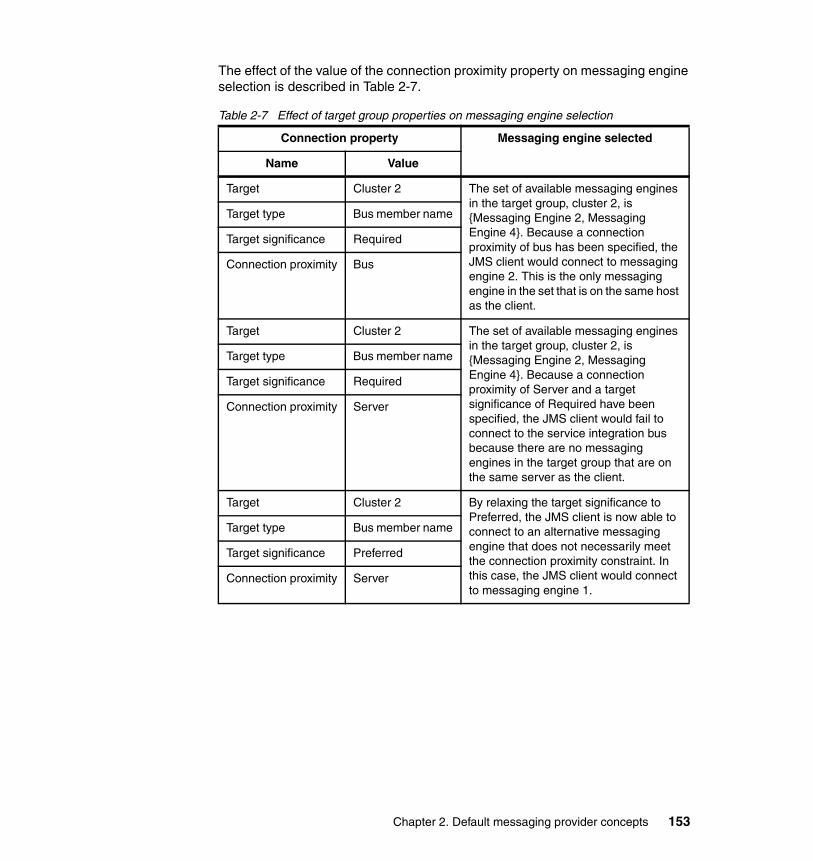
The effect of the value of the connection proximity property on messaging engine selection is described in Table 2-7.
Table 2-7 Effect of target group properties on messaging engine selection
Connection property Messaging engine selected
Name Value
Target Cluster 2 The set of available messaging engines in the target group, cluster 2, is {Messaging Engine 2, Messaging Engine 4}. Because a connection proximity of bus has been specified, the JMS client would connect to messaging engine 2. This is the only messaging engine in the set that is on the same host as the client.
Target type Bus member name
Target significance Required
Connection proximity Bus
Target Cluster 2 The set of available messaging engines in the target group, cluster 2, is {Messaging Engine 2, Messaging Engine 4}. Because a connection proximity of Server and a target significance of Required have been specified, the JMS client would fail to connect to the service integration bus because there are no messaging engines in the target group that are on the same server as the client.
Target type Bus member name
Target significance Required
Connection proximity Server
Target Cluster 2 By relaxing the target significance to Preferred, the JMS client is now able to connect to an alternative messaging engine that does not necessarily meet the connection proximity constraint. In this case, the JMS client would connect to messaging engine 1.
Target type Bus member name
Target significance Preferred
Connection proximity Server
Chapter 2. Default messaging provider concepts 153

154 WebSphere Application Server V7 Messaging Administration Guide

Chapter 3. Default messaging provider configuration and management
This chapter discusses how to set up and configure a bus using the administrative console. It contains the following topics:
� “Configuration and management overview” on page 156� “SIB service” on page 156� “Creating a bus” on page 158� “Adding bus members” on page 161� “Creating and using a WebSphere MQ Server” on page 182� “Creating destinations” on page 186� “Adding messaging engines to a cluster” on page 191� “Manually creating messaging engine policies” on page 177� “Setting up a foreign bus connection to a service integration bus” on page 192� “Working with foreign buses” on page 192� “Problem determination” on page 198
3
© Copyright IBM Corp. 2009. All rights reserved. 155
3.1 Configuration and management overview
When configuring the bus for use with the default messaging provider, the minimum tasks that apply are:
� The creation and configuration of a bus (optionally including security)� The addition of at least one bus member� The definition of destinations of one variety or another
When configuring the bus to communicate with WebSphere MQ, you can set up a WebSphere MQ link through a foreign bus connection or a WebSphere MQ Server. The minimum tasks for both are:
� To use a WebSphere MQ link:
a. Create and configure a bus.
b. Add at least one bus member and any required destinations.
c. Set up a foreign bus connection link to an MQ queue manager.
d. Add alias destinations that points to the MQ queues via the MQ link foreign bus connection.
� To use a WebSphere MQ Server:
a. Create and configure a bus.
b. Add one server bus member.
c. Create a WebSphere MQ Server definition and add it to the bus as a member.
d. Create one or more queue destinations that correspond to the MQ queues.
3.2 SIB service
The SIB service enables an application server for service integration activities. When an application server is added to a bus, it automatically has its SIB service enabled, starting with the next server startup. Having the SIB service allows an application server to have active messaging engines and to be used as a provider endpoint for default messaging connection factories.
Note: It is not likely that you will need to view or modify the SIB service settings. However, for awareness, we include instructions on how to do so in this book.
156 WebSphere Application Server V7 Messaging Administration Guide

The port on which the SIB service listens can be looked up on the server’s configuration window:
1. Select Servers → Application Servers.
2. Select the application server.
3. Under Communications, expand the Ports heading. SIB_ENDPOINT_ADDRESS is the port used by SIB Service for that server.
The settings for the SIB service of an application server can be found on the administrative console:
1. Select Servers → Application Servers.
2. Select the application server.
3. Under Server messaging, select SIB service. See Figure 3-1.
Figure 3-1 SIB Service window
The window for SIB service has two options:
– Enable service at server startup.
This option is not enabled on a server by default. However, it is automatically enabled if you add a server to a bus. If you disable the SIB
Note: SIB service listens on a number of ports, not just the port for SIB_ENDPOINT_ADDRESS. SIB_ENDPOINT_SECURE_ADDRESS is also available, and is used for secure communications. Tunnelled and tunnelled secure endpoints are also provided (jfap/http/tcp and jfap/http/ssl/tcp). Refer to the Information Center for more details.
Chapter 3. Default messaging provider configuration and management 157

service, then any messaging engines defined on the server will not be started.
– Configuration reload enabled.
This option allows the SIB service to dynamically activate certain changes to a bus configuration during run time. Creation, deletion, or modification of a destination or mediation takes effect almost immediately on a running system. If a new destination is created, it becomes available for use without having to restart servers or messaging engines.
A matching flag must also be enabled on each bus on which you want to enable configuration reload. This flag is enabled by default on every bus, but can be disabled if you want. To modify the flag either way, do the following:
i. Select Service Integration → Buses.ii. Select a bus.iii. Modify the Configuration reload enabled flag as appropriate.iv. Save the changes.
3.3 Creating a bus
No buses are defined by default. Before creating a bus, give some thought to bus security. You can enable it when you create the bus or you can enable bus security later (see Chapter 4, “Securing the service integration bus” on page 203).
Note: When the SIB service is enabled on z/OS systems, the Control Region Adjunct (CRA) gets started.
Note: Configuration changes that require a server restart are:
� If you are adding a bus member to any bus for the first time (to start the SIB service)
� If you modify the custom properties of a messaging engine
158 WebSphere Application Server V7 Messaging Administration Guide

To create a bus, do the following:
1. Select Service Integration → Buses and click New. See Figure 3-2.
Figure 3-2 First window of the bus creation wizard
This window gives the only opportunity to provide the name of the new bus. You cannot change the name of a bus after it has been created, but you can create any number of buses in a cell and delete old ones. Make your bus name unique and meaningful. This is a required field.
The Bus security check box allows security to be enabled on the bus. If administrative security is enabled, then the check box is selected by default.
If bus security is enabled, the next steps provide options for transport security (SSL connections for clients) and the security domain to use.
If administrative security is disabled and the check box for bus security is selected, the wizard will open screens to enable administrative security.
2. Once you have completed the wizard steps, click Finish and save your changes.
Chapter 3. Default messaging provider configuration and management 159

Configuring bus propertiesTo do this:
1. Select Service Integration → Buses.
2. Select the bus that you want to configure. The bus configuration window isdisplayed. See Figure 3-3.
Figure 3-3 Bus configuration window
160 WebSphere Application Server V7 Messaging Administration Guide

The following properties can be set:
– Inter-engine transport chain
This is the transport chain used for communication between messaging engines in this bus. This must correspond to one of the transport chains defined in the messaging engine inbound transports settings for the server. When you specify the name of a transport chain, that chain must be defined to all servers hosting messaging engines in the bus. Otherwise, some messaging engines might not be able to communicate with their peers in the bus. The default transport chain is InboundBasicMessaging.
– Discard messages
Use this field to specify whether messages on a deleted message point should be retained at a system exception destination or can be discarded.
– Configuration reload enabled
Select this option to enable certain changes to the bus configuration to be applied without requiring the messaging engines to be restarted. If you select this option, make sure that the matching flag on the SIB service is also enabled. See 3.2, “SIB service” on page 156.
– High message threshold
Enter a threshold above which the messaging system will take action to limit the addition of more messages to a message point. When a messaging engine is created on this bus, the value of this property sets the default high message threshold for the messaging engine.
This is a per-queue point threshold, not a single threshold for an entire messaging engine.
3. Click Apply or OK and save your changes.
3.4 Adding bus members
A member of a bus can be an application server, a cluster, or a WebSphere MQ Server. For a cluster or application server, a messaging engine is automatically created within the bus. The messaging engine requires a message store for persistent and temporary storage. This message store can be implemented as flat files (file store) or as tables in a database (data store). WebSphere MQ Servers do not have a messaging engine created, and so do not have to specify a message store. This is addressed in 3.5, “Creating and using a WebSphere MQ Server” on page 182.
Chapter 3. Default messaging provider configuration and management 161

3.4.1 Adding a single server as a bus member
To add a member to the bus:
1. Select Service Integration → Buses.
2. Select the bus to which you want to add a member.
3. Select Bus members in the Additional Properties section.
4. On the Bus members window, click Add.
5. Select Server as the type of bus member (Figure 3-4).
Figure 3-4 First window of Add bus member wizard
Click Next.
6. Every messaging engine has a message store associated with it. This window allows you to select the type. See Figure 3-5.
Figure 3-5 Select the message store type
162 WebSphere Application Server V7 Messaging Administration Guide

What you select here determines how you proceed through the wizard. This example will complete the wizard using the File store option.
7. Select File Store and click Next. The file store configuration window appears. See Figure 3-6.
Figure 3-6 File store configuration window
Chapter 3. Default messaging provider configuration and management 163

The following properties can be set:
– Log size
The size of the log file. The minimum value is 10 MB. The default is 1 → 0 MB. This file does not grow and so does not have minimum and maximum file sizes.
– Default log directory path
Select this radio button to accept the default system-generated path for the log file. The file name will be Log. The directory path will be ${USER_INSTALL_ROOT}/filestores/com.ibm.ws.sib/<me_name>.<me_build>/log/.
– Log directory path
Select this radio button and supply a non-default directory path for the log file. The file name will be Log.
– Settings for permanent and temporary stores
The permanent and temporary store files can have identical settings. If you select this option, only one set of store file settings will appear in the window below this option (marked Permanent and Temporary stores). If this option is not selected, there will be separate sets for the Permanent store and the Temporary store displayed in the window (in that order).
– Minimum permanent store size
The minimum size of the permanent store file. The minimum value is 0 MB. The default is 200 MB.
– Unlimited permanent store size
Select this check box to remove any maximum size restrictions on the permanent store file.
– Maximum permanent store size
This setting will be ignored if the permanent store size is set to be unlimited. The minimum value is 50 MB. The default is 500 MB.
– Default permanent store directory path
Select this radio button to accept the default system-generated path for the permanent store file. This directory path will be ${USER_INSTALL_ROOT}/filestores/com.ibm.ws.sib/me_name.me_build/store/.
– Permanent store directory path
Select this radio button and supply a non-default directory path for the permanent store file. The file name for the permanent store file will be PermanentStore. The file name for the temporary store file will be
164 WebSphere Application Server V7 Messaging Administration Guide
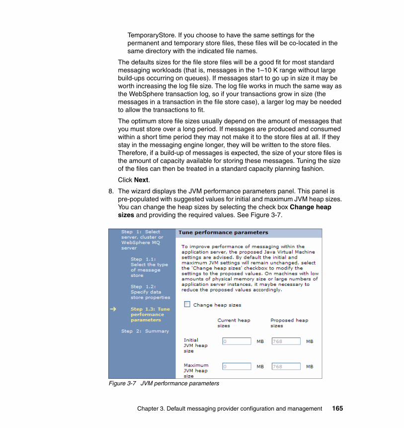
TemporaryStore. If you choose to have the same settings for the permanent and temporary store files, these files will be co-located in the same directory with the indicated file names.
The defaults sizes for the file store files will be a good fit for most standard messaging workloads (that is, messages in the 1–10 K range without large build-ups occurring on queues). If messages start to go up in size it may be worth increasing the log file size. The log file works in much the same way as the WebSphere transaction log, so if your transactions grow in size (the messages in a transaction in the file store case), a larger log may be needed to allow the transactions to fit.
The optimum store file sizes usually depend on the amount of messages that you must store over a long period. If messages are produced and consumed within a short time period they may not make it to the store files at all. If they stay in the messaging engine longer, they will be written to the store files. Therefore, if a build-up of messages is expected, the size of your store files is the amount of capacity available for storing these messages. Tuning the size of the files can then be treated in a standard capacity planning fashion.
Click Next.
8. The wizard displays the JVM performance parameters panel. This panel is pre-populated with suggested values for initial and maximum JVM heap sizes. You can change the heap sizes by selecting the check box Change heap sizes and providing the required values. See Figure 3-7.
Figure 3-7 JVM performance parameters
Chapter 3. Default messaging provider configuration and management 165

Select Next.
9. Select Finish and save your changes.
For more information about file stores, refer to the WebSphere Information Center and “File stores” on page 95.
3.4.2 Adding a server to a bus using the default data store
If you elect to use the default data store, a Derby database will be created automatically and initialized with the messaging engine tables. To create a bus member that automatically creates a messaging engine and uses the default Derby database, do the following from the second window of the Add bus member wizard. See Figure 3-5 on page 162.
1. Select Data Store.
2. Select Next. The data store configuration window appears (Figure 3-8).
Figure 3-8 Data source window with default settings option checked
3. Select Next and complete the wizard.
166 WebSphere Application Server V7 Messaging Administration Guide

3.4.3 Adding a bus member with a non-default data store
This section discusses the steps required to create a bus member using a different data source from the default. In this section we use DB2 as an example.
Creating a databaseThe first step is to create the new database and define the user IDs allowed to access the database. The privileges required are outlined in the Information Center. Refer to the Data Stores topic under the service integration bus administration topics for further information.
For example, the user ID for a DB2 database must have the following privileges:
� SELECT, INSERT, UPDATE, and DELETE privileges on the tables� CREATETAB authority on the database� USE privilege on the table space� CREATEIN privilege on the schema
Use the sibDDLGenerator command to generate the DDL statements needed to create the data store for the messaging engine, including the proper privileges. For information about using this command, see the sibDDLGenerator command topic in the Information Center. An example of the command is:
sibDDLGenerator.sh -server db2 -version 9.1 -schema TEST -user TESTUSER
This command outputs the DDL to standard out. It may be useful to redirect the output to a file as follows:
sibDDLGenerator.sh -server db2 -version 9.1 -schema TEST -user TESTUSER > TEST.ddl
Creating a J2C authentication aliasTo define access to the new database, define a J2C authentication alias containing the user ID and password defined in “Creating a database” on page 167.
1. Select Security → Secure Administration, applications and infrastructure.
2. Under Authentication, expand the Java Authentication and Authorization Service section and select J2C Authentication data.
3. Click New.
a. Provide a name for this alias. The alias name will be used later to identify this name as the one to access the database.
b. Provide a user ID and password that have permission to access the resource that you will be using.
Chapter 3. Default messaging provider configuration and management 167
c. Click OK and save your changes.
Creating a JDBC provider and data sourceWith this step, you define the database to the application server. First, a JDBC provider is defined to tell the application server how to find the libraries required to access the database:
1. Select Resources → JDBC → JDBC Providers.
2. Select the appropriate scope for the JDBC Provider. If you are adding a cluster as a bus member, select that cluster as the scope. If you are adding a server as a bus member, select the server as the scope.
3. Click New.
a. Select a database type. In this example, we use DB2.
b. Select the provider type. This is dependent on the database type. For a DB2 database, select DB2 Universal JDBC Driver Provider.
c. Select the implementation type. For DB2, use Connection pool data source.
Click Next.
4. Supply the absolute directory paths of the JDBC driver files according to the instructions on the window.
5. Click Next and then click Finish.
6. Create a data source for the bus member. Select Resources → JDBC → Data Sources.
7. Set the scope for the new data source.
8. Click New to create a new data source. Then:
a. Provide a unique and meaningful data source name.
b. Provide a JNDI name for the data source. Remember this name because you must provide it when adding your cluster or server to the bus.
c. Provide the J2C authentication alias that contains the credentials to connect to the database successfully. Click Next.
d. Select the existing DB2 Universal JDBC Driver Provider. Click Next.
Note: When the data source is being created at cluster scope, each node that has a server in the cluster must have the DB2 JAR files available on it. The DB2UNIVERSAL_JDBC_DRIVER_PATH variable must be set appropriately for every node.
168 WebSphere Application Server V7 Messaging Administration Guide

e. Provide the database name, driver type, and, optionally, the server name. Get this information from your database administrator.
• The database name must be the name of an existing DB2 database.
• The driver type is 2 if the DB2 database exists locally or is catalogued locally. If the database is only available on a remote host, then the driver type is 4 and you must enter the server name.
f. Click Next and Finish and save your changes.
Adding the bus memberOnce the database and supporting definitions are in place, the bus member can be added. To add the bus member, do the following:
1. Select Service Integration → Buses. Select the bus that you want.
2. Select Bus members in the Additional Properties section.
3. Click Add.
4. Select the server or cluster to add to the bus and click Next.
5. Select Data store and click Next.
Note: There is no need to provide a component-managed authentication alias at this stage. That will be specified later in the data store of the messaging engine. Specifying the alias in either location is supported, but for tighter security control, we recommend that you specify it in the messaging engine’s data store.
Chapter 3. Default messaging provider configuration and management 169

6. Select Use existing data source. See Figure 3-9
Figure 3-9 Data source window with existing settings option checked
Then:
– Supply the data source JNDI name of the JDBC data source that you have created. This is the only required field.
– The schema name will be the default.
– Select the appropriate authentication alias to connect to the database. This should be the same one that you selected when you configured the data source.
7. Ensure that the Create tables box is checked. The messaging engine will create all of the tables that it needs in the database when it starts for the first time.
8. Complete the wizard.
Note: If you are sharing this database among messaging engines, each must have a unique schema. You can specify a unique schema here.
170 WebSphere Application Server V7 Messaging Administration Guide
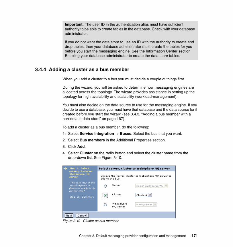
3.4.4 Adding a cluster as a bus member
When you add a cluster to a bus you must decide a couple of things first.
During the wizard, you will be asked to determine how messaging engines are allocated across the topology. The wizard provides assistance in setting up the topology for high availability and scalability (workload-management).
You must also decide on the data source to use for the messaging engine. If you decide to use a database, you must have that database and the data source for it created before you start the wizard (see 3.4.3, “Adding a bus member with a non-default data store” on page 167).
To add a cluster as a bus member, do the following:
1. Select Service Integration → Buses. Select the bus that you want.
2. Select Bus members in the Additional Properties section.
3. Click Add.
4. Select Cluster on the radio button and select the cluster name from the drop-down list. See Figure 3-10.
Figure 3-10 Cluster as bus member
Important: The user ID in the authentication alias must have sufficient authority to be able to create tables in the database. Check with your database administrator.
If you do not want the data store to use an ID with the authority to create and drop tables, then your database administrator must create the tables for you before you start the messaging engine. See the Information Center section Enabling your database administrator to create the data store tables.
Chapter 3. Default messaging provider configuration and management 171

Click Next.
The wizard will show panels that allow you to set the Messaging Engine policy. See Figure 3-11.
Figure 3-11 Messaging engine policy assistance
Selecting the Enable messaging engine policy assistance? check box provides valuable guidance in selecting how the messaging engine topology will be created.
Select each policy type in the table to see the topology information at the bottom of the window and a description in the Help area of the console.
172 WebSphere Application Server V7 Messaging Administration Guide

The options are:
– High availability
This pattern creates a single messaging engine and ensures that it is always available.
A new One of N policy type will be added to DefaultCoreGroup. No preferred servers are configured. The messaging engine will run on any active server.
– Scalability
Selecting the scalability pattern will create a messaging engine for every server in the cluster. A new One of N policy type will be added to DefaultCoreGroup for each messaging engine. Each policy specifies a preferred server for the messaging engine and the Preferred server only option is selected to ensure that the messaging engine will only run on that server.
– Scalability with high availability
Selecting the scalability with high availability pattern will create a messaging engine for every server in the cluster.
Each messaging engine will be able to be hosted by one other server (as well as the one to which it is assigned). Each server in the cluster will be able to host one other messaging engine.
A new One of N policy type will be added to DefaultCoreGroup for each messaging engine.
Each policy specifies two preferred servers for the messaging engine and the Preferred server only option is selected to ensure that the messaging engine will only run on servers from that list.
The Failback option is also selected so that when a server fails the messaging engine will be activated on another server in the list of preferred servers.
– Custom
Selecting the custom pattern will allow a unique pattern to be created for the server cluster. This is only recommended for advanced users. If you select this option, you will be provided with the chance to create the messaging engines and specify the settings for the core group policies for each.
Select the policy type and click Next.
5. Select the type of the message store (file store or data store) and click Next.
Chapter 3. Default messaging provider configuration and management 173
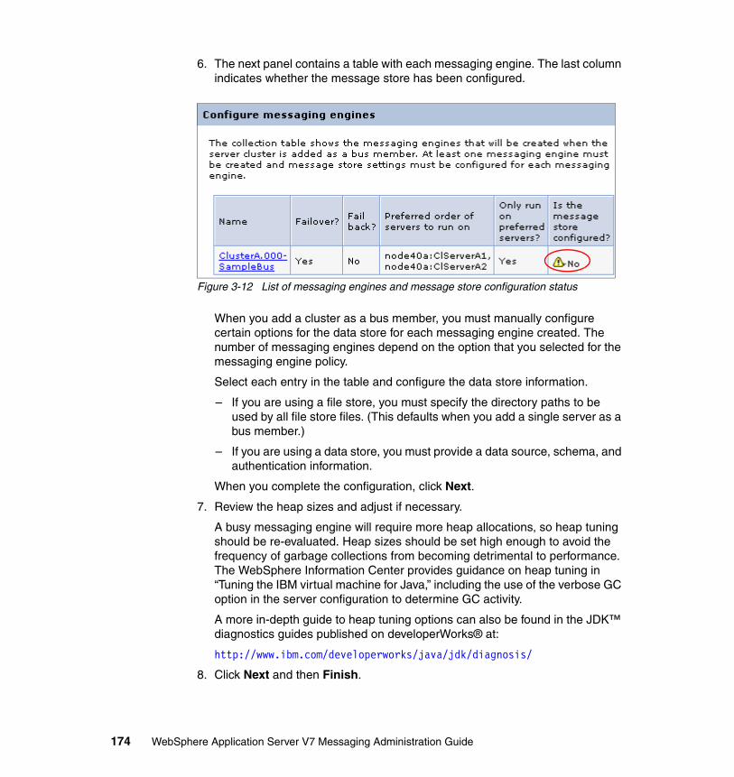
6. The next panel contains a table with each messaging engine. The last column indicates whether the message store has been configured.
Figure 3-12 List of messaging engines and message store configuration status
When you add a cluster as a bus member, you must manually configure certain options for the data store for each messaging engine created. The number of messaging engines depend on the option that you selected for the messaging engine policy.
Select each entry in the table and configure the data store information.
– If you are using a file store, you must specify the directory paths to be used by all file store files. (This defaults when you add a single server as a bus member.)
– If you are using a data store, you must provide a data source, schema, and authentication information.
When you complete the configuration, click Next.
7. Review the heap sizes and adjust if necessary.
A busy messaging engine will require more heap allocations, so heap tuning should be re-evaluated. Heap sizes should be set high enough to avoid the frequency of garbage collections from becoming detrimental to performance. The WebSphere Information Center provides guidance on heap tuning in “Tuning the IBM virtual machine for Java,” including the use of the verbose GC option in the server configuration to determine GC activity.
A more in-depth guide to heap tuning options can also be found in the JDK™ diagnostics guides published on developerWorks® at:
http://www.ibm.com/developerworks/java/jdk/diagnosis/
8. Click Next and then Finish.
174 WebSphere Application Server V7 Messaging Administration Guide

After configuration, the panel showing the list of bus members will include the messaging engine policy information. See Figure 3-13.
Figure 3-13 Cluster as bus member with high availability
Chapter 3. Default messaging provider configuration and management 175

9. Select Servers → Core groups → Core group settings.
10.Click DefaultCoreGroup, then select Policies in the Additional Properties section. You can see that the policy is associated when the cluster bus member is included in the list of policies. See Figure 3-14.
Figure 3-14 HA policy
3.4.5 Modifying the messaging engine policy
After you add a cluster as a bus member, you can change the messaging engine policy selection. The core group policies will be automatically altered for the new selection.
To modify the HA policy of the cluster bus member, do the following:
1. Select Service Integration → Buses. Select the bus that you want.
2. Select Bus members in the Additional Properties section.
176 WebSphere Application Server V7 Messaging Administration Guide

3. Select the cluster bus member. The policy for the cluster bus member can be modified here. See Figure 3-15.
Figure 3-15 Modify cluster bus member policy
4. Select the policy and click Apply.
3.4.6 Manually creating messaging engine policies
When you add a cluster to a bus using the messaging engine policy assistance, the core group policies, including the preferred servers for the messaging engine, are defined for you. If you did not use the assist feature, you can create policies for the messaging engines manually.
Note: Before attempting to configure a system for workload management and high availability, consult the following:
� Section 2.4, “High availability and workload management” on page 130
� The “Configuring high availability and workload sharing of service integration” topic in the WebSphere Information Center
Chapter 3. Default messaging provider configuration and management 177

Setting up a policy with the appropriate values can cause many different behaviors, including the following:
� A messaging engine will have an affinity for one particular server in the cluster. If that server fails, then the messaging engine will run on other servers, but will move back to the preferred server as soon as it becomes available. This is set up by having a One-of-N Policy defined with one preferred server configured, the Preferred servers only property set to false, and the Fail back property set to true.
� A messaging engine will run on only one specific server. This means that the messaging engine cannot fail over to another server in the cluster and will only ever run on the defined server. This can be set up by having a One of N policy with one preferred server and the preferred servers only property set to true.
To create a core group policy for a messaging engine, do the following:
1. Select Servers → Core groups → Core group settings.
2. Select DefaultCoreGroup.
3. Select Policies in the Additional Properties section. This shows you the list of policies defined for the core group. You will see two default policies. Do not delete or modify these policies. See Figure 3-16.
Figure 3-16 Predefined core group policies in the default core group
178 WebSphere Application Server V7 Messaging Administration Guide

4. Click New.
5. From the drop-down list, select One of N Policy. Click Next.
6. In the next panel:
a. Enter a name for the new policy. It is helpful if the name includes the name of the messaging engine for which you are creating this policy.
b. Enable Fail back and Preferred servers only as desired. These settings can be changed later.
See Figure 3-17.
Figure 3-17 Defining a new policy
Click Apply.
Chapter 3. Default messaging provider configuration and management 179

A warning will state that you must define at least one match criteria (Figure 3-18). Match criteria are name and value pairs used to match server components, such as messaging engines.
Figure 3-18 Match criteria warning
7. Select Match criteria in the Additional Properties section.
Important: Be aware that if you set preferred servers only, this can prevent the messaging engine from being highly available. If the messaging engine or the server that it runs on fails or stops and no other servers that are preferred are available, then the messaging engine cannot be started on other servers that are available in the cluster. They are not preferred, and only preferred servers can be used.
180 WebSphere Application Server V7 Messaging Administration Guide

8. Click New. See Figure 3-19. Enter type for the name and WSAF_SIB for the value. This match criteria will match any messaging engine.
Figure 3-19 Defining match criteria for any messaging engine
Click OK.
9. Click New to define another set of match criteria.
10.Enter WSAF_SIB_MESSAGING_ENGINE for the name and the messaging engine name for the value. Click OK.
11.Return to your policy by clicking the policy name in the navigation trail.
12.Click Preferred servers in the Additional Properties section.
Chapter 3. Default messaging provider configuration and management 181

13.Select the servers that you want to configure as preferred and click Add. You can select as many preferred servers as you want. All preferred servers must be servers that are in the cluster on which the messaging engine is defined. Do not select a node agent or deployment manager. See Figure 3-20.
Figure 3-20 Selecting preferred servers for a core group policy
Preferred servers have an order of preference. The higher up the list of preferred servers, the more preferred the server will be. To move a server up or down the list, select the server and click Move up or Move down. If failback is enabled, then a messaging engine will fail over to the highest available server in the list.
14.Click OK and save your changes.
3.5 Creating and using a WebSphere MQ Server
A WebSphere MQ server provides a direct client connection between a service integration bus and queues on a WebSphere MQ queue manager or (for WebSphere MQ for z/OS) queue-sharing group. For interoperation with WebSphere Application Server Version 7.0, the version of WebSphere MQ must be WebSphere MQ for z/OS Version 6 or later or WebSphere MQ (distributed platforms) Version 7 or later. For more information see 2.2.7, “WebSphere MQ servers” on page 120.
In this section we will show you how to create a WebSphere MQ Server and add it as a member of a bus.
182 WebSphere Application Server V7 Messaging Administration Guide

3.5.1 Creating a WebSphere MQ Server
To create a WebSphere MQ Server, do the following:
1. Select Servers → WebSphere MQ servers.
2. Click New. You will see the WebSphere MQ Server configuration window. See Figure 3-21.
Figure 3-21 WebSphere MQ Server configuration window
Chapter 3. Default messaging provider configuration and management 183

The following properties must be set:
– Name.
Enter a meaningful name for the WebSphere MQ Server. This is used for administration purposes.
– WebSphere MQ server name.
This is the name (as defined in WebSphere MQ) of the MQ queue manager or the queue sharing group.
– Server type.
Here you define the type of the server that you want to connect to, a queue manager or a queue sharing group.
– Use bindings transport mode if available.
If this is selected, bindings transport mode will always be used in preference to client transport mode. Otherwise, client transport mode will be used.
– WebSphere MQ host.
The DNS host name or IP address of the machine that is hosting the MQ Queue manager.
– WebSphere MQ port.
The TCP/IP port number (default 1414) used to connect to the WebSphere MQ queue manager.
– Transport chain name.
Select the appropriate transport chain from the drop-down list (basic or secure). This is used to establish an outbound network connection to the WebSphere MQ Server. See Table 2-4 on page 92 for further information:
– WebSphere MQ Channel.
This is the name of the connection channel, as defined in WebSphere MQ.
Additional properties for security and resource discovery are also found in the configuration page (not shown in Figure 3-21 on page 183). In general, the defaults are acceptable. Information about these can be found using the help available for the configuration page in the administrative console.
3. Use the Test Connection button to ensure that the settings are correct and that a connection can be made to the queue manager or queue sharing group.
4. Click OK and save your changes.
On the WebSphere MQ system, the queue manager (or queue sharing group) must have a SVRCONN channel that matches the one that you set in step 2, and
184 WebSphere Application Server V7 Messaging Administration Guide
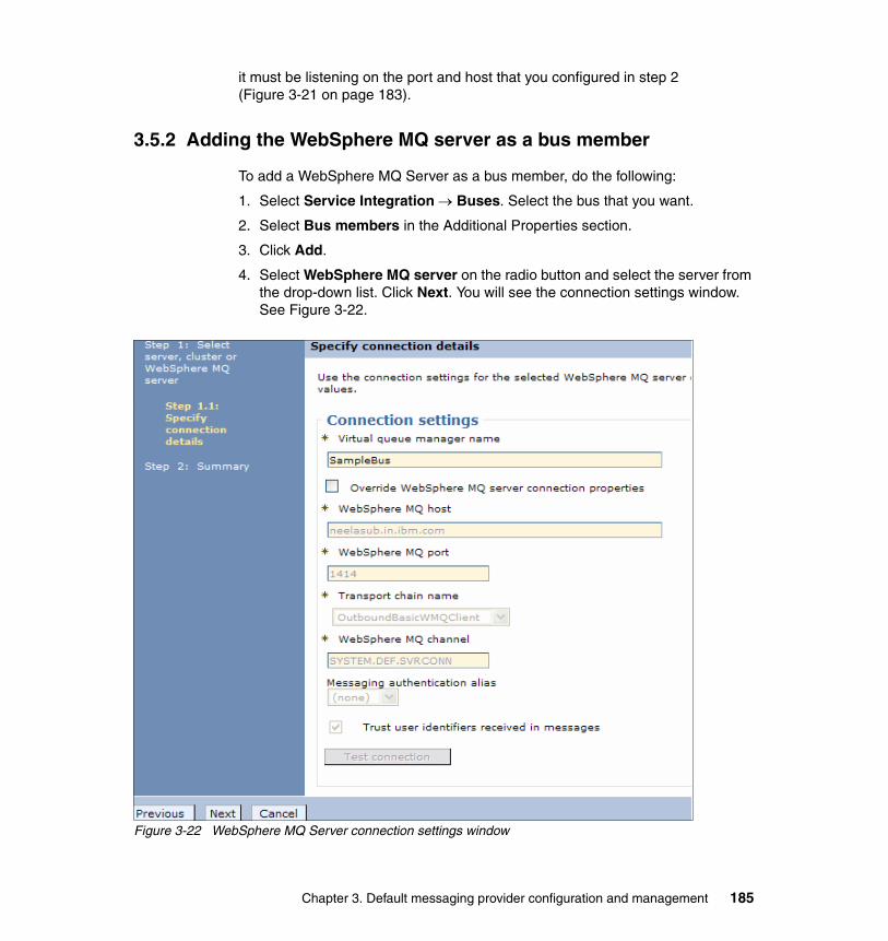
it must be listening on the port and host that you configured in step 2 (Figure 3-21 on page 183).
3.5.2 Adding the WebSphere MQ server as a bus member
To add a WebSphere MQ Server as a bus member, do the following:
1. Select Service Integration → Buses. Select the bus that you want.
2. Select Bus members in the Additional Properties section.
3. Click Add.
4. Select WebSphere MQ server on the radio button and select the server from the drop-down list. Click Next. You will see the connection settings window. See Figure 3-22.
Figure 3-22 WebSphere MQ Server connection settings window
Chapter 3. Default messaging provider configuration and management 185

The virtual queue manager name is the name of the service integration bus that the WebSphere MQ queue manager sees. While we recommend that the virtual queue manager name and the name of the service integration bus are the same, they don’t have to be the same.
This window also gives you the opportunity to review and override some of the WebSphere MQ Server connection properties. This may be useful in a multiple-bus topology where you may need bus-specific settings for the server.
If you wish to override the inherited connection settings, select the Override WebSphere MQ server connection properties check box and alter the connection settings as desired.
5. Click Next and Finish and save your changes.
3.6 Creating destinations
This section discusses how to create destinations on the bus.
3.6.1 Creating a queue destination
Queue destinations are destinations that you can configure for point-to-point messaging:
1. Select Service Integration → Buses.
2. Select the bus on which you want to create a queue.
3. Select Destinations in the Destination resources section. See Figure 3-23.
Figure 3-23 Default destinations
186 WebSphere Application Server V7 Messaging Administration Guide

The Destinations window shows two destinations that are created automatically for you:
– The Default.Topic.Space is a default topic space that can be used for publish/subscribe messaging. It can be deleted.
– The _SYSTEM.Exception.Destination is a built-in queue to which undelivered messages are routed. It cannot be deleted.
4. Click New (Figure 3-24).
Figure 3-24 Options when creating a new destination
5. Select Queue from the radio button list and click Next.
6. Provide an identifier and optional description for the queue (Figure 3-25).
Figure 3-25 Provide an identifier for your destination
Chapter 3. Default messaging provider configuration and management 187

If your application uses the JMS interface, it is not sufficient to create a destination on the bus. A JMS destination referencing the bus destination must also be created (see “JMS queue configuration” on page 23).
Click Next.
7. Select a bus member for the queue point for this queue from the list for the queue. Click Next.
Figure 3-26 Select a bus member for the queue
8. Click Next → Finish.
9. Open the new destination by clicking its name in the list of destinations (Figure 3-23 on page 186). Additional settings not exposed in the wizard are available in the configuration page for the destination. These settings allow you set defaults for the destination. In many cases, the message producer can override these settings:
– Quality of service definitions, including reliability settings (See “Reliability” on page 78.)
– Message priority (See “JMS destination properties” on page 28.)
– Strict message order (See “Strict message ordering” on page 79.)
– Exception destination information and number of delivery attempts before a message is sent to the exception destination (See 2.2.4, “Exception destinations” on page 105.)
– The operations allowed by message producers to this queue (Send and receive.)
– A destination and bus for reply messages
10.Save your changes.
Note: The identifier value specified here must match the Queue name property of the JMS queue definition.
188 WebSphere Application Server V7 Messaging Administration Guide

3.6.2 Creating a topic space destination
Topic space destinations are destinations that can be configured for publish/subscribe messaging:
1. Select Service Integration → Buses.
2. Select the bus on which you want to create a topic space.
3. Select Destinations in the Destination resources section.
4. Click New.
5. Select Topic space from the list and click Next.
6. Provide an identifier for your topic space. Click Next.
7. Click Finished.
8. Open the configuration page for the new topic by clicking its name in the list of topics.
Similar to queue destinations, you will find additional settings that allow you to define defaults for the topic space. Like queue destinations, you will find settings for reliability, message priority, exception destinations, and so on. In addition, you will find the option to require authorization checks for topics and whether to enable auditing for those checks.
9. Save your changes.
3.6.3 Creating an alias destination
Alias destinations refer to another destination, potentially on a foreign bus connection, providing an extra level of indirection for messaging applications. An alias destination can also be used to override some of the values specified on the target destination, such as default reliability and maximum reliability. Foreign bus connections are discussed in 2.1.6, “Foreign bus connections” on page 80.
To create an alias destination:
1. Select Service Integration → Buses.
2. Select the bus on which you want to create a topic space.
3. Select Destinations in the Destination resources section.
4. Click New.
5. Select Alias from the list and click Next.
Chapter 3. Default messaging provider configuration and management 189

The properties to note are:
– Identifier
This field is the destination name as known by the applications.
– Bus
Enter the name of the bus used by applications when referring to the alias destination.
If the destination that clients will attempt to access is known to them to be on a foreign bus connection, then select that bus from the menu. An example of this is if a foreign destination is configured in the JMS layer and you want to redirect client requests for that destination.
If the bus does not appear in the list, select Other, specify from the list, and enter the name of the bus in the text box.
If you leave the Bus field empty, the alias destination is created on the local bus.
– Target identifier
Enter the identifier of the target destination to which you want this alias destination to route messages. If the alias destination is targeting a queue provided by WebSphere MQ, type the value as a concatenation of the queue name and the queue manager name (queue_name@qmanager_name), for example, Queue1@Qmgr2.
– Target bus
Enter the name of the bus or foreign bus connection hosting the target destination. This can be the name of a foreign bus connection representing a WebSphere MQ network. The default is the name specified for the Bus property.
Override any of the other values on the window that you want to override for the destination.
Click Next.
6. Click Finished.
7. Save your changes.
190 WebSphere Application Server V7 Messaging Administration Guide

3.7 Adding messaging engines to a cluster
If you must define additional messaging engines for a cluster, you can do this with the following steps:
1. Ensure that you have defined a data source that the new messaging engine will use for its data store before starting this section (see “Creating a JDBC provider and data source” on page 168).
2. Select Service Integration → Buses. Select the bus that you want to use.
3. Select Bus members in the Additional Properties section.
4. Select the cluster bus member to which you want to add an additional messaging engine.
5. Under additional properties, select Messaging engines. This displays the list of messaging engines that are defined for the cluster bus member. See Figure 3-27.
Figure 3-27 Messaging engines as part of a cluster bus member
6. Click Add messaging engine.
7. Select the type of message store and click Next.
8. Enter the required information for the message store. For information about using multiple message stores, see 3.4.3, “Adding a bus member with a non-default data store” on page 167.
9. Click Next → Finish and save your changes.
Chapter 3. Default messaging provider configuration and management 191

3.8 Working with foreign buses
A foreign bus represents a connection to another messaging network. The connection can be to another service integration bus (in the same or different cell) or to a WebSphere MQ network. Foreign bus concepts are discussed in 2.1.6, “Foreign bus connections” on page 80.
3.8.1 Setting up a foreign bus connection to a service integration bus
To use a destination on a foreign bus do the following:
1. Create a bus on each network. We will refer to these as bus1 and bus2.
2. Add a bus member to each bus to host the messaging engines for the link.
3. Create a foreign bus connection on both buses.
On bus1:
a. Select Direct connection as the bus connection type.
b. Select Service integration bus as the foreign bus type.
c. Specify a messaging engine on bus1 to act as the local endpoint of the connection.
Important: If you have more than one messaging engine defined on a cluster bus member and do not define additional core group policies to set up preferred servers, then all messaging engines will start and run on the first server to become available. See the next section for information about setting up preferred servers.
Note: For simplicity, the examples in this section assume a queue destination. If you are working with connections between two service integration buses, these examples apply equally to a topic space destination.
In order to subscribe/publish to a topic in the WebSphere MQ space using using native WebSphere MQ PubSub or a broker, you would need to configure the Publish/Subscribe bridge that is shipped with WebSphere Application Server. For more information see the Publish/subscribe bridge article in the Information Center at:
http://publib.boulder.ibm.com/infocenter/wasinfo/v7r0/topic/com.ibm.websphere.pmc.nd.multiplatform.doc/concepts/cjc0017_.html
192 WebSphere Application Server V7 Messaging Administration Guide

d. Specify bus2 and a messaging engine on bus2 to act as the endpoint of the foreign bus connection.
e. Specify a name for the service integration bus link.
On bus2, do the reverse:
a. Select Direct connection as the bus connection type.
b. Select Service integration bus as the foreign bus type.
c. Specify a messaging engine on bus2 to act as the local endpoint of the connection.
d. Specify bus1 and a messaging engine on bus1 to act as the endpoint of the foreign bus connection.
e. Specify the same name that you used on bus1 as the name for the service integration bus link.
Restart the messaging engines and test the connection.
4. Create the queue destination on bus2.
An example of a foreign bus connection to another service integration bus can be seen in 4.10, “Configuring foreign bus connections” on page 282.
3.8.2 Setting up a foreign bus connection to an MQ queue manager
A WebSphere MQ link allows your service integration bus to exchange messages with a WebSphere MQ queue manager.
To use a destination on a foreign bus do the following:
1. In WebSphere Application Server, create a bus (bus1 in this example) and add a member to it.
2. In WebSphere MQ:
a. Create a queue manager.
b. Create a receiver channel to receive messages from the WebSphere application.
c. You also have the option to send messages from WebSphere MQ to a service integration bus. If you plan to use this option, you also must create a sender channel.
3. Create a foreign bus connection in WebSphere Application Server.
On bus1:
a. Provide a name for the foreign bus and the MQ link.
Chapter 3. Default messaging provider configuration and management 193

b. Specify a virtual queue manager name. This is the name that the WebSphere MQ network will see as the queue manager name for the bus.
c. Specify the WebSphere MQ receiver channel name (and optionally specify the WebSphere MQ sender channel name, host, and port details). The WebSphere MQ channel names will be used to create the MQLinkSender and MQLinkReceiver channel definitions.
d. Test the connection.
4. Create a queue on WebSphere MQ.
5. Create an alias destination on bus1 that references the queue on WebSphere MQ. Messages sent to the alias destination will be forwarded on to WebSphere MQ.
In this example, a foreign bus connection will be created from bus1 to the WASqm queue manager on WebSphere MQ. A receiver channel has been defined on WebSphere MQ (Figure 3-28).
Figure 3-28 WebSphere MQ configuration
First, you must define a foreign bus connection for the local bus:
1. Select Service integration → Buses. Select the bus that you want to use.
2. Select Foreign bus connections in the Topology section.
3. Click New.
4. Select a direct connection and click Next.
5. Select WebSphere MQ from the menu and click Next.
Note: Before creating these definitions, review the information in 2.2.6, “WebSphere MQ links” on page 110.
194 WebSphere Application Server V7 Messaging Administration Guide
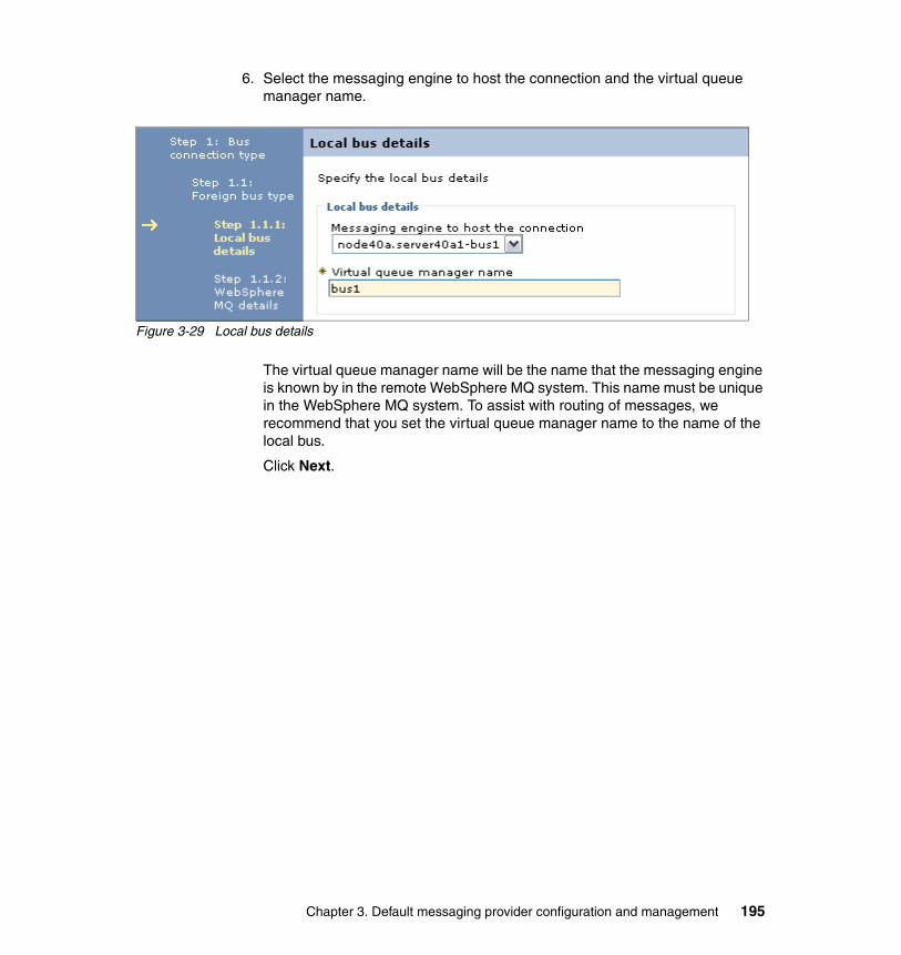
6. Select the messaging engine to host the connection and the virtual queue manager name.
Figure 3-29 Local bus details
The virtual queue manager name will be the name that the messaging engine is known by in the remote WebSphere MQ system. This name must be unique in the WebSphere MQ system. To assist with routing of messages, we recommend that you set the virtual queue manager name to the name of the local bus.
Click Next.
Chapter 3. Default messaging provider configuration and management 195
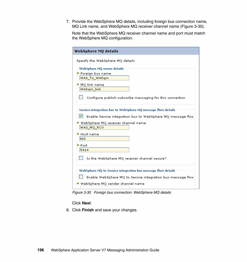
7. Provide the WebSphere MQ details, including foreign bus connection name, MQ Link name, and WebSphere MQ receiver channel name (Figure 3-30).
Note that the WebSphere MQ receiver channel name and port must match the WebSphere MQ configuration.
Figure 3-30 Foreign bus connection: WebSphere MQ details
Click Next.
8. Click Finish and save your changes.
196 WebSphere Application Server V7 Messaging Administration Guide

9. Test the connection (Figure 3-31). Note that the Test connection button only allows you to test the connection from WebSphere Application Server to WebSphere MQ. To test the connection from WebSphere MQ to WebSphere Application Server, use the PING CHANNEL command on WebSphere MQ.
Figure 3-31 Test the connection
3.8.3 Routing messages from a local bus to a remote bus
To route a message from an application connected to a bus (bus1) to a queue on another bus (bus2, or WebSphere MQ), do the following:
1. Establish a foreign bus connection between the two buses and create the target queue on the remote bus (for simplicity, let us say bus2).
2. Create a connection factory for the default messaging provider on the system hosting the application. Provide the JNDI name and the connection information for bus1.
Chapter 3. Default messaging provider configuration and management 197
3. Applications can send messages to queues on the foreign bus with any of the following configuration options:
– Create an alias destination (most common method).
Create an alias queue that maps the queue destination on the local bus to a target queue on the foreign bus. The JMS queue definition would only need to specify the alias queue name. The alias will resolve it to the target destination on the foreign bus.
See 3.6.3, “Creating an alias destination” on page 189, for information about creating an alias destination.
– Direct connection: No additional configuration required.
For a JMS application sending messages, the JMS queue definition identifies the queue name (the target queue on the foreign bus) and the foreign bus name.
– Using a foreign destination (rare).
Create a foreign destination on the local bus that acts as a proxy to forward requests to the queue on the foreign bus. When you define the foreign destination, you provide the target bus name and the target queue name.
A JMS destination specifies the foreign destination. The JMS destination bus and queue name match the foreign bus name and queue name of the foreign destination.
You can set properties (for example, the default priority) on a foreign destination. These properties apply when an application in the local bus uses the foreign destination.
Determine the option that you want to use and perform the necessary configuration.
4. Create a JMS destination and provide the information appropriate for the option that you selected in the previous step.
5. Save the configuration changes and restart the server.
3.9 Problem determination
The following information is presented to help you become familiar with successful messaging engine startup and some common problems.
198 WebSphere Application Server V7 Messaging Administration Guide

3.9.1 Normal startup messages
Example 3-1 shows an example of what you can expect to see in systemOut.log on server startup for a messaging engine that starts successfully.
Example 3-1 Successful messaging engine start
...CWSID0016I: Messaging engine Node1.server1-ITSOBus is in state Joined....CWSID0016I: Messaging engine Node1.server1-ITSOBus is in state Starting....CWSID0016I: Messaging engine Node1.server1-ITSOBus is in state Started....
When you have more than one messaging engine in a bus, you will also see the messaging engines communicate with each other. Every messaging engine in the bus connects to every other messaging engine in the bus, as shown in Example 3-2.
Example 3-2 Messaging engine connections
...CWSIT0028I: The connection for messaging engine Node1.server1-ITSOBus in bus ITSOBus to messaging engine Node2.server2-ITSOBus started....CWSIP0382I: messaging engine B68588EF698F4527 responded to subscription request, Publish Subscribe topology now consistent. ...
Note: When you start a server that is part of a cluster bus member, the messaging engine will not always be started. In a high-availability topology, only one server in the cluster will have a messaging engine activated on it, and this messaging engine might already be started.
If this is the case, then you will see the messaging engine in the state Joined, but not Starting or Started. This is perfectly normal and means that the messaging engine is in a stand-by state, waiting to be activated should the currently active instance of the messaging engine become unavailable.
Chapter 3. Default messaging provider configuration and management 199
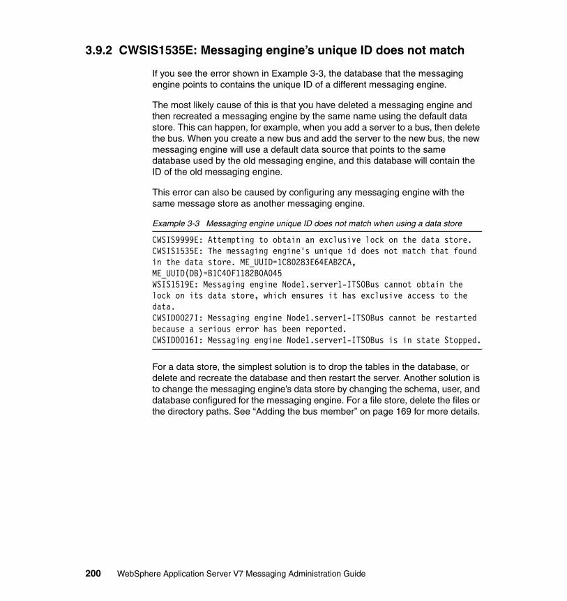
3.9.2 CWSIS1535E: Messaging engine’s unique ID does not match
If you see the error shown in Example 3-3, the database that the messaging engine points to contains the unique ID of a different messaging engine.
The most likely cause of this is that you have deleted a messaging engine and then recreated a messaging engine by the same name using the default data store. This can happen, for example, when you add a server to a bus, then delete the bus. When you create a new bus and add the server to the new bus, the new messaging engine will use a default data source that points to the same database used by the old messaging engine, and this database will contain the ID of the old messaging engine.
This error can also be caused by configuring any messaging engine with the same message store as another messaging engine.
Example 3-3 Messaging engine unique ID does not match when using a data store
CWSIS9999E: Attempting to obtain an exclusive lock on the data store.CWSIS1535E: The messaging engine's unique id does not match that found in the data store. ME_UUID=1C80283E64EAB2CA, ME_UUID(DB)=B1C40F1182B0A045WSIS1519E: Messaging engine Node1.server1-ITSOBus cannot obtain the lock on its data store, which ensures it has exclusive access to the data.CWSID0027I: Messaging engine Node1.server1-ITSOBus cannot be restarted because a serious error has been reported.CWSID0016I: Messaging engine Node1.server1-ITSOBus is in state Stopped.
For a data store, the simplest solution is to drop the tables in the database, or delete and recreate the database and then restart the server. Another solution is to change the messaging engine’s data store by changing the schema, user, and database configured for the messaging engine. For a file store, delete the files or the directory paths. See “Adding the bus member” on page 169 for more details.
200 WebSphere Application Server V7 Messaging Administration Guide

3.9.3 CWSIT0019E: No suitable messaging engine
This exception shown in Example 3-4 can be thrown to a JMS client on a createConnection call. Causes of this exception include:
� The JMS connection factory cannot contact an SIB service (for out of cell JMS clients only). Check that the provider endpoints listed in the connection factory match the host and port for the SIB services on the servers. Ensure that the SIB services are enabled and that the servers are started.
� The bus name defined in the JMS connection factory does not match the name of a bus defined in WebSphere.
� No messaging engines on the named bus are active.
Example 3-4 Exception on createConnection call
javax.jms.JMSException: CWSIA0241E: An exception was received during the call to the method JmsManagedConnectionFactoryImpl.createConnection: com.ibm.websphere.sib.exception.SIResourceException: CWSIT0019E: No suitable messaging engine is available in bus ITSOBus.
Chapter 3. Default messaging provider configuration and management 201

202 WebSphere Application Server V7 Messaging Administration Guide

Chapter 4. Securing the service integration bus
The service integration bus (also referred to as the bus, or SIbus) provides a robust, scalable messaging infrastructure. The messaging infrastructure allows applications to utilize messaging paradigms, connecting Java Platform, Enterprise Edition (Java EE), or external messaging services. This chapter looks at securing the components of the bus. It contains the following sections:
� “Overview” on page 204� “Understanding the example environment” on page 206� “Creating a secure bus” on page 209� “Securing the data store” on page 229� “Connecting to a secure bus” on page 234� “Configuring authorization on queue destinations” on page 237� “Configuring authorization on temp destinations” on page 243� “Configuring authorization on topics” on page 250� “Configure application resources” on page 265� “Configuring foreign bus connections” on page 282� “Other considerations” on page 299� “AdminTask wsadmin commands for security” on page 301
4
© Copyright IBM Corp. 2009. All rights reserved. 203

4.1 Overview
Figure 4-1 illustrates the components of a bus. In this specific topology, the bus has a cluster as the bus member, which is configured to use the default high-availability policy type, which means that the bus has a single active instance of a messaging engine in the bus. If a messaging engine instance fails, then a messaging engine is started on another member of the cluster.
Figure 4-1 Bus components
In Figure 4-1, JMS messaging is used to illustrate the bus connections and flow. In this example an EJB client connects to the default messaging provider. The client uses the Java messaging API to connect to the JMS connection factory and the JMS queue destination. These JMS components are configured to connect to the messaging engine and destination on the bus.
Figure 4-1 also illustrates that with this messaging engine topology, there is one active instance of a message engine in one cluster member. Clients running in
Note: The bus can be configured in different topology combinations. However, the underlying bus components and the components that can be secured in the bus remain the same.
Cluster bus member
SIBusqueue
destination
JMSqueue
destination
JMSconnection
factory
EJB MDB
JMSActivationSpec
JMS standard API
Datasource
Bus
JDBC provider
Cluster bus member
SIBusqueue
destination
Messagingengine(ME)
JMSqueue
destination
JMSconnection
factory
EJB MDB
JMSActivationSpec
JMS standard API
Messagingengine(ME)
204 WebSphere Application Server V7 Messaging Administration Guide
other members of the cluster (or in different clusters) send messages across the network to the messaging engine.
Once messages are passed to the bus, they are routed to their final destination. In Figure 4-1 on page 204, the messaging engine communicates with the destination configured in the activation specification. The activation specification points to the message-driven bean (MDB) for the receiving destination.
Part of the bus messaging infrastructure requirement is to be able to support reliable messaging. To help satisfy this requirement the messaging engine has the capability to utilize a data store. Figure 4-1 on page 204 shows a database as the data store implementation. The message engine can also be configured to use a file store.
When considering these component interactions in relation to their security requirements, the following bus components can have security applied:
� Client connections to the messaging engine are secured using role-based authorization.
� Communication channels used by remote clients are secured using SSL.
� The data store is secured using a J2C authentication alias.
� Bus destinations are secured using role-based authorization.
Connections to the bus and the bus destinations are the access control points of the bus when security is enabled.
The bus uses a role-based authorization model. Users and groups can be added to the bus configuration under one of the predefined bus roles that define the access permissions being granted to the added user/group.
The roles of the bus are summarized as the following by the information center (http://publib.boulder.ibm.com/infocenter/wasinfo/v7r0/topic/com.ibm.websphere.pmc.nd.multiplatform.doc/concepts/cjr0450_.html):
� Connector role: Grants the user or group permission to connect to the local bus.
� Sender role: Grants the user or group the permission to send a message to a destination.
� Receiver role: Grants the user or group the permission to receive a message from a destination.
Tip: Remember to simplify management of security. A leading practice is to grant access to user groups rather than individual users.
Chapter 4. Securing the service integration bus 205

� Browser role: Grants the user or group the permission to browse messages on a destination.
� Creator role: When temporary destinations are being used the creator role allows the user to create the temporary destination.
Figure 4-2 illustrates what roles users and groups can be added to for the different destination types.
Figure 4-2 Role types applicable for destination type
4.2 Understanding the example environment
This section details the environment that is used in the examples for securing of the bus. The Trade performance benchmark application (which can be found at http://www-01.ibm.com/software/webservers/appserv/was/performance.html) will be used to help illustrate the application’s role in providing credentials and where to configure this in the application configuration.
Creator
Browser
Receiver
Sender
RoleType
TemporaryDestination
Prefix
PortWebService
ForeignAliasTopicSpace
Queue
Destinations
206 WebSphere Application Server V7 Messaging Administration Guide

Figure 4-3 shows the secure bus that will be configured for this example.
Figure 4-3 Environment topology
Cell
Node Node
Application Server
Trade
Node Agent
LDAP TradeDB
TradeStreamerTopic TradeStreamerTCF TradeStreamerAS
TradeBrokerJSD Trade.Topic.Space
Trade Bus
TradeBrokerQCF TradeBrokerAS
Node
DeploymentManager
TradeBrokerQueue
TradeME
Application Server
Trade
Node Agent
Trade Cluster
ME
TradeCluster.000-TradeBus
Chapter 4. Securing the service integration bus 207

The following will also be applied in the environment:
� The default, high-availability policy type setting is the messaging engine topology of choice.
� A database is used for persistence in the message engine.
� A stand-alone LDAP is used as the user registry.
The directory information tree for the LDAP is shown in Figure 4-4. This information will be useful later in the example when groups are assigned to specific destinations.
Figure 4-4 LDAP directory information tree
Note: This configuration has multiple machines with a clustered cell environment. From a security standpoint, the configuration for a stand-alone application server is the same.
organizationalUnitou=unit1
or ga niza ti ono=i bm
o= ib m o=i bm o= ibm
groupOfUniqueNamescn=group12Members
uid2
groupOfUniqueNamescn=group13Members
uid1uid3
groupOfUniqueNamescn=admingroup11
Membersadmin1admin2
or ga niza ti ono=i bm
o= ibm
o= ibm
un it 1
un it 1
un it 1
o= ibmor ga niza ti on
o=i bm
o= ibm
o= ibm
u ni t1
u ni t1
u ni t1
o= ibm
groupOfNamescn=group11Members
uid1uid2
inetOrgPersonuid=uid1
inetOrgPersonuid=uid2
inetOrgPersonuid=uid3
inetOrgPersonuid=admin1
inetOrgPersonuid=admin2
countryc=us
organizationo=ibm
o rg ani zat io no=i bm
o =ib m
o =ib m
uni t1
uni t1
uni t1
o =ib m
organizationalUnitou-users11
organizationalUnitou-adminusers
208 WebSphere Application Server V7 Messaging Administration Guide

Pre-configuration requirementsBefore securing the bus environment, note the following items:
� Configuring bus security requires that administrative security is active.
� If activating security on a bus that is in use, it is important to stop the bus and ensure that there are no in-doubt transactions relating to the existing message engines. Transaction recovery for these in-doubt transactions will not be able to successfully complete once security is enabled.
4.3 Creating a secure bus
The following sections show how to configure a secure bus using the administrative console and wsadmin scripts. The starting environment includes the nodes, servers, clusters, and data sources defined at the cluster level. In this step the bus trade Bus is added to the environment. Figure 4-5 illustrates the addition of the bus.
Figure 4-5 Add the secure bus Trade Bus
Cell
Node Node
Application Server
Node Agent
LDAP TradeDB
Trade Bus
Node
DeploymentManager
TradeME
Application Server
Node Agent
Trade Cluster
Chapter 4. Securing the service integration bus 209

4.3.1 Creating a secure bus using the administrative console
If you are creating a new messaging environment, we recommend that security is enabled at bus creation time. The default configuration choices in the process are aligned with securing the bus.
1. Open the administration console and select Service Integration → Buses to navigate to the Buses panel.
2. Click New to start the service integration bus wizard.
3. On the Create a new bus panel of the wizard enter the name of the bus. Ensure that the Bus Security check box is checked (Figure 4-6).
Figure 4-6 Create a new bus panel
Click Next.
Note: This triggers the beginning of the bus security configuration wizard. If a bus is created without security enabled, security can be enabled later by navigating to the Buses → (bus name) → Security panel and clicking the Launch Bus Secutity Wizard. The wizard that runs when security is enabled post creation is exactly the same as the security wizard panels if security is enabled at the time of bus creation.
210 WebSphere Application Server V7 Messaging Administration Guide

Click Next on the Introduction panel (Figure 4-7).
Figure 4-7 Security wizard Introduction panel
Chapter 4. Securing the service integration bus 211

4. Read the Specify transport level security panel and decide whether SSL communications for clients should be enforced. We recommend that SSL be used to protect the confidentiality and integrity of the message data, as shown in Figure 4-8.
Figure 4-8 Security wizard: Select the transport level security panel
212 WebSphere Application Server V7 Messaging Administration Guide

Click Next.
5. On the panel that follows, you are asked to select the security domain.
In V7, you configure administrative security and the default application security configuration at the global security level. In addition, you can create multiple security domains that provide independent security configuration for applications. For example, the global security configuration can use one type of user registry, while an application domain might use another.
Security domains can be associated with application servers, clusters, service integration buses, or the entire cell.
When configuring the security for the bus, this step identifies the security domain for the bus. The options are:
– Global security.– Inherit cell level security domain.– Use existing security domain. – Create a new security domain.
Why use this setting: Setting "Require clients use SSL protected transports" has the following benefits:
� Credentials (such as passwords) are encrypted when sent to the messaging engine.
� Messages sent between clients and the messaging engine will be encrypted.
� Unencrypted messaging transports will not be started, preventing misconfigured clients from connecting by mistake. (In mixed version buses, only V7 messaging engines have this behavior.)
� Credentials sent between messaging engines to establish trust will be encrypted in transit.
� Messages sent between messaging engines will be encrypted in transit.
Chapter 4. Securing the service integration bus 213

With global security all security functions are controlled using a single configuration, as shown in Figure 4-9.
Figure 4-9 Global security domain configuration
The second option is to inherit the cell level security domain. A cell level security domain is one that has been associated with the entire cell, providing default application security settings for the cell. Administrative security is provided by the global security settings.
For the bus this means that users and groups are authorized using the user registry specified at the cell domain level.
Cell
Global Security Domain
Node
DeploymentManager
Node
Node Agent
Node
Node Agent
Bus
ApplicationServer
ApplicationServer
GlobalLDAP
214 WebSphere Application Server V7 Messaging Administration Guide

Figure 4-10 shows a simple representation of the inherit cell level security domain option. This model can be used to isolate the administration and application security applications.
Figure 4-10 Inherit cell security domain
Cell
GlobalLDAP
CellLDAP
Global Security Domain
DeploymentManager Node Agent Node Agent
Bus
ApplicationServer
ApplicationServer
Node Node Node
Cell Security Domain
Chapter 4. Securing the service integration bus 215
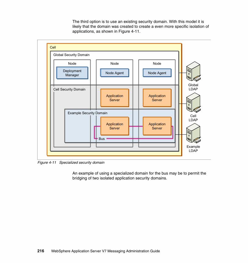
The third option is to use an existing security domain. With this model it is likely that the domain was created to create a even more specific isolation of applications, as shown in Figure 4-11.
Figure 4-11 Specialized security domain
An example of using a specialized domain for the bus may be to permit the bridging of two isolated application security domains.
Cell
GlobalLDAP
CellLDAP
Global Security Domain
DeploymentManager Node Agent Node Agent
ApplicationServer
ApplicationServer
ExampleLDAP
Bus
ApplicationServer
ApplicationServer
Node Node Node
Example Security Domain
Cell Security Domain
216 WebSphere Application Server V7 Messaging Administration Guide
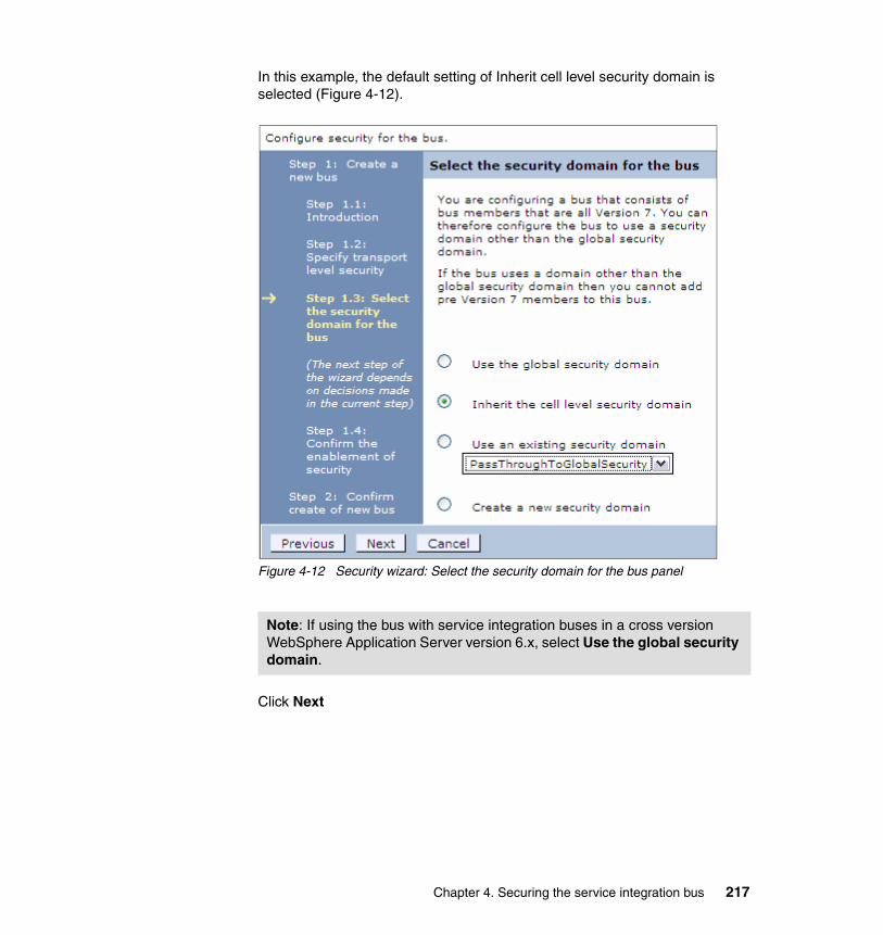
In this example, the default setting of Inherit cell level security domain is selected (Figure 4-12).
Figure 4-12 Security wizard: Select the security domain for the bus panel
Click Next
Note: If using the bus with service integration buses in a cross version WebSphere Application Server version 6.x, select Use the global security domain.
Chapter 4. Securing the service integration bus 217

6. The Confirm the enablement of security panel provides a summary of the security-related configuration choices (Figure 4-13). Click Next.
Figure 4-13 Security wizard: Confirm the enablement of security panel
218 WebSphere Application Server V7 Messaging Administration Guide

7. Click Finish (Figure 4-14).
Figure 4-14 Confirm create of new bus panel
8. Save the configuration. You do not need to restart anything to make the bus available.
4.3.2 Creating a secure bus using wsadmin
You can also create a secure bus using the wsadmin and scripting environment. The following examples show the commands that will create and configure a secure bus. These commands are written using the jython scripting language and were executed using wsadmin.
In this flow it can be seen that each example command represents the pages of the wizard shown in the previous section.
1. Create a bus with security enabled (Example 4-1).
Example 4-1 Create the bus
AdminTask.createSIBus('[-bus "Trade Bus" -busSecurity true ]')
Chapter 4. Securing the service integration bus 219
2. If the default is inherit cell level security domain, then the security domain for the bus does not need to be specified, as this is the default. However, if the security domain is to not be the default, then one of the following commands can be used to specify either global security domain or a specific security domain:
– (Optional) Global security domain example (Example 4-1 on page 219)
Example 4-2 Map resource for Global security domain
AdminTask.mapResourceToSecurityDomain('[-securityDomainName PassThroughToGlobalSecurity -resourceName SIBus="Trade Bus"]')
– (Optional) Custom security domain (Example 4-3)
Example 4-3 Map resource for custom security domain
AdminTask.mapResourceToSecurityDomain('[-securityDomainName "SIBus Domain" -resourceName SIBus="Trade Bus"]')
3. Require SSL communications by clients (Example 4-4).
Example 4-4 Configure SSL required
AdminTask.modifySIBus('[-bus "Trade Bus" -busSecurity true -permittedChains SSL_ENABLED ]')
4. Save the configuration (Example 4-5).
Example 4-5 Save configuration
AdminCOnfig.save()
4.3.3 Understanding the secure bus defaults
In the rest of this chapter you will repeatedly need to start a security configuration from the security configuration page for a bus. There are two ways to access this page:
� Navigate to Service integration → Buses and select the Enabled link of the bus in the security column. This opens the security configuration page for the bus (Figure 4-15 on page 221).
� Select Buses → bus_name → Security.
From this point on, when the instructions say “Open the security configuration for the bus,” use one of the previous methods.
220 WebSphere Application Server V7 Messaging Administration Guide

Before you consider extending the security design or change the defaults taken during the security wizard, it is important to understand the default configuration.
Open the security configuration for the bus (Figure 4-15).
Figure 4-15 Security for Trade Bus
Chapter 4. Securing the service integration bus 221

The following sections highlight key defaults of the different sections of the Security for ExampleBus panel.
Enable bus securityThe Enable bus security check box is checked (Figure 4-16). This means that:
� All connections to the bus will be authenticated.� Access to destinations will be authorized.
Figure 4-16 Enable bus security on the Security for Example Bus panel
Credentials for authentication and authorization are passed via the connection factory.
Inter-engine authentication aliasThe inter-engine authentication alias is not required if your bus only contains messaging engines running on v7 bus members. It is only needed for mixed version buses with members at 6.1 or earlier.
This field contains the name of the authentication alias used to authorize communication between messaging engines on the bus. The value specified is used to ensure the prevention of unauthorized clients or messaging engines from establishing a connection.
Why use this setting The bus authorization policy is only applied at the messaging engine to which the client is connected. This means that if a client sends a message to a destination on a different messaging engine to which it is connected, the authorization check occurs on the messaging engine to which the client is connected. This means that all the messaging engines in a bus are in the same trust domain, and as a result they must establish that the other messaging engines are trustworthy.
In a bus consisting of only V7 messaging engines, this trust is established using specially constructed LTPA tokens. This feature is only supported by V7 messaging engines. V6 and V6.1 messaging engines make use of a user ID and password. As a result, this setting is only required in buses with one or more v6.x messaging engines.
A bus consisting of a single v6.x messaging engine should still have this property set, as no validation is performed to verify how many messaging engines have been configured for the bus.
222 WebSphere Application Server V7 Messaging Administration Guide

Secure network communicationsThe Permitted transports section defines which transport channel chains are used. When configuring the bus using the bus wizard, the Require clients use SSL protected transports option was checked. This means that in the resulting configuration, only SSL transport chains are active and available for clients to use.
This configured value is shown in Figure 4-17.
Figure 4-17 Permitted transports section on the Security for Example Bus panel
A transport chain represents ways that the application server can connect and be connected to using network communication protocols. Transport channels are shared by resources in the application server. They are not specific to a bus or an application. For more information see the information center:
http://publib.boulder.ibm.com/infocenter/wasinfo/v7r0/topic/com.ibm.websphere.nd.multiplatform.doc/info/ae/ae/crun_chain_transport.html
To simplify the configuration of transports, the application server configuration has predefined common communication channels. This includes channels used for inbound communication and outbound communication for the bus. When communications for the bus are secured using SSL, some of the default transport chains are automatically disabled. The permitted transports of the bus and their enabled status for SSL communications is shown in Figure 4-18 on page 225.
Table 4-1 Permitted transports
Note: New in V7, only permitted chains are started.
Transport chain Inbound/outbound Enabled with SSL
InboundBasicMessaging Inbound
InboundSecureMessaging Inbound
InboundBasicMQLink Inbound
InboundSecureMQLink Inbound
Chapter 4. Securing the service integration bus 223

If SSL is configured as part of the configuration, only secured transports are enabled for the bus.
For more information see:
� Bus inbound transports and bus
http://publib.boulder.ibm.com/infocenter/wasinfo/v7r0/topic/com.ibm.websphere.pmc.nd.multiplatform.doc/concepts/cjk1000_.html
� Bus outbound transports
http://publib.boulder.ibm.com/infocenter/wasinfo/v7r0/topic/com.ibm.websphere.pmc.nd.multiplatform.doc/concepts/cjk2000_.html
BootstrapBasicMessaging Outbound
BootstrapSecureMessaging Outbound
BootstrapTunneledMessaging
Outbound
BootstrapTunneledSecureMessaging
Outbound
OutboundBasicMQLink Outbound
OutboundSecureMQLink Outbound
OutboundBasicWMQClient Outbound
OutboundSecureWMQClient
Outbound
Transport chain Inbound/outbound Enabled with SSL
224 WebSphere Application Server V7 Messaging Administration Guide

Enable bus auditThe Audit section shows that for secure buses, the default is that audit is enabled (Figure 4-18).
Figure 4-18 Audit section on the Security for Example Bus panel
Note: If you want to select different inbound and outbound transport chains for the bus, the third radio selection in the permitted transports section can be selected.
When this option is selected, you must manually configure the transports used by the bus by selecting the Permitted transports link in the Additional Properties section on the Security for bus_name panel.
For more information see:
http://publib.boulder.ibm.com/infocenter/wasinfo/v7r0/topic/com.ibm.websphere.pmc.nd.multiplatform.doc/sibresources/SIBPermittedTransports_DetailForm.html
Remember that the selection of any non-secured transport chains will potentially compromise the security of message transports. Proceed down this path with caution.
Note: Tip regarding MQ transports: If the bus is not configured to communicate with WebSphere MQ, the application server will not start the transport channels used by MQ. Thus, you are not required to manually administer the transport chains to remove MQ transport channels. If MQ connections are not configured, the transport chains will not be started.
Tip: This in itself does not enable auditing of the bus security. The default for the audit service is disabled. The application server’s audit service would also need to be enabled for the bus audit features to be activated.
Chapter 4. Securing the service integration bus 225
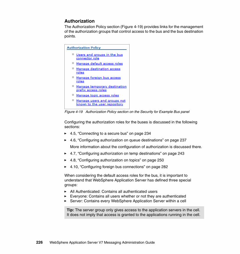
AuthorizationThe Authorization Policy section (Figure 4-19) provides links for the management of the authorization groups that control access to the bus and the bus destination points.
Figure 4-19 Authorization Policy section on the Security for Example Bus panel
Configuring the authorization roles for the buses is discussed in the following sections:
� 4.5, “Connecting to a secure bus” on page 234
� 4.6, “Configuring authorization on queue destinations” on page 237
More information about the configuration of authorization is discussed there.
� 4.7, “Configuring authorization on temp destinations” on page 243
� 4.8, “Configuring authorization on topics” on page 250
� 4.10, “Configuring foreign bus connections” on page 282
When considering the default access roles for the bus, it is important to understand that WebSphere Application Server has defined three special groups:
� All Authenticated: Contains all authenticated users� Everyone: Contains all users whether or not they are authenticated � Server: Contains every WebSphere Application Server within a cell
Tip: The server group only gives access to the application servers in the cell. It does not imply that access is granted to the applications running in the cell.
226 WebSphere Application Server V7 Messaging Administration Guide

Default connector roleThe default for the connector roles is that the server group is in the connector role. This means that all servers in the cell are able to connect to the bus.
Figure 4-20 shows the server group mapped into the connector role. This panel is navigated to by selecting the Users and Groups in the bus connector role link.
Figure 4-20 Users and groups in bus connector role
Default access rolesWhen a bus is created, the default access roles include the All Authenticated group. Unless explicitly modified when a destination is created, a destination inherits this access. The AllAuthenticated group has access to all destinations by default, though not all roles.
If you choose to set access controls at the default level it is important to remember that by default, the default access roles are inherited by all destination types for which the roles are applicable.
Recommendation: The all authenticated default group should be removed from the bus configuration to prevent a destination from mistakenly inheriting permissions from these defaults.
Chapter 4. Securing the service integration bus 227
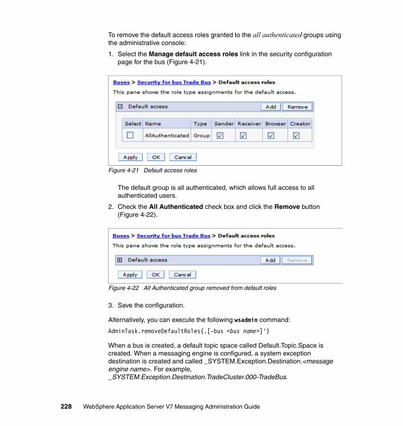
To remove the default access roles granted to the all authenticated groups using the administrative console:
1. Select the Manage default access roles link in the security configuration page for the bus (Figure 4-21).
Figure 4-21 Default access roles
The default group is all authenticated, which allows full access to all authenticated users.
2. Check the All Authenticated check box and click the Remove button (Figure 4-22).
Figure 4-22 All Authenticated group removed from default roles
3. Save the configuration.
Alternatively, you can execute the following wsadmin command:
AdminTask.removeDefaultRoles(.[-bus <bus name>]')
When a bus is created, a default topic space called Default.Topic.Space is created. When a messaging engine is configured, a system exception destination is created and called _SYSTEM.Exception.Destination.<message engine name>. For example, _SYSTEM.Exception.Destination.TradeCluster.000-TradeBus.
228 WebSphere Application Server V7 Messaging Administration Guide
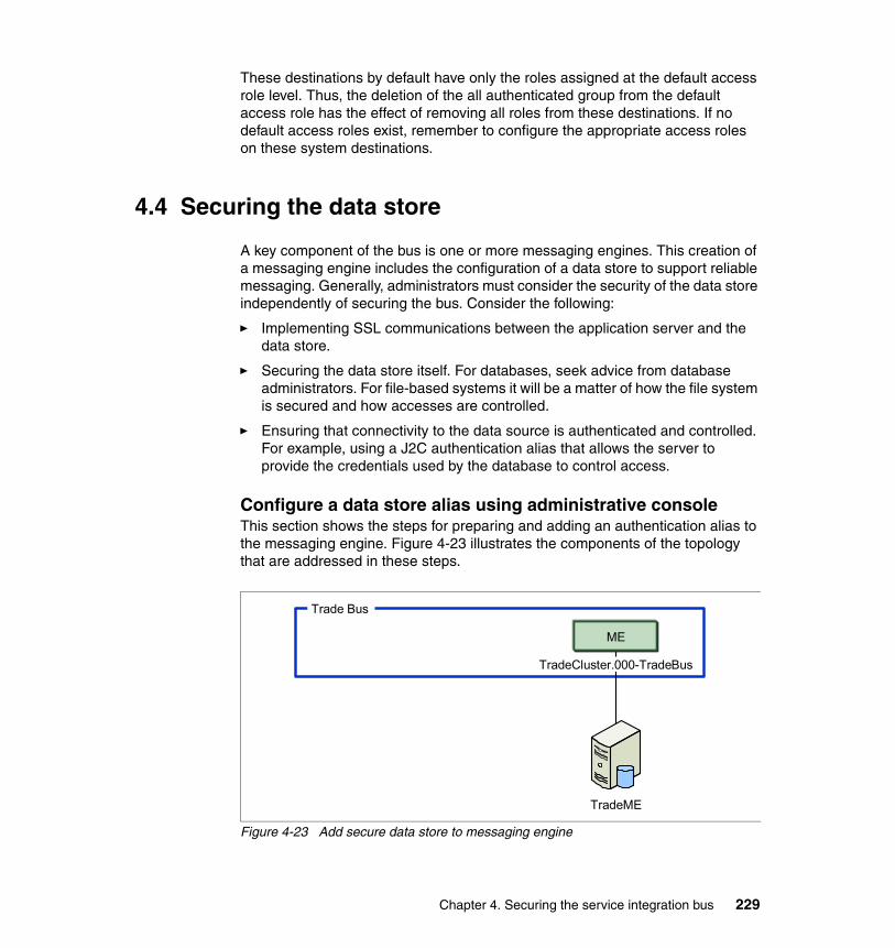
These destinations by default have only the roles assigned at the default access role level. Thus, the deletion of the all authenticated group from the default access role has the effect of removing all roles from these destinations. If no default access roles exist, remember to configure the appropriate access roles on these system destinations.
4.4 Securing the data store
A key component of the bus is one or more messaging engines. This creation of a messaging engine includes the configuration of a data store to support reliable messaging. Generally, administrators must consider the security of the data store independently of securing the bus. Consider the following:
� Implementing SSL communications between the application server and the data store.
� Securing the data store itself. For databases, seek advice from database administrators. For file-based systems it will be a matter of how the file system is secured and how accesses are controlled.
� Ensuring that connectivity to the data source is authenticated and controlled. For example, using a J2C authentication alias that allows the server to provide the credentials used by the database to control access.
Configure a data store alias using administrative consoleThis section shows the steps for preparing and adding an authentication alias to the messaging engine. Figure 4-23 illustrates the components of the topology that are addressed in these steps.
Figure 4-23 Add secure data store to messaging engine
Trade Bus
TradeME
ME
TradeCluster.000-TradeBus
Chapter 4. Securing the service integration bus 229
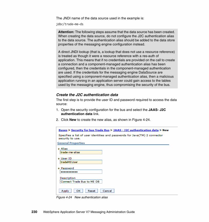
The JNDI name of the data source used in the example is:
jdbc/trade-me-ds
Create the J2C authentication dataThe first step is to provide the user ID and password required to access the data source:
1. Open the security configuration for the bus and select the JAAS- J2C authentication data link.
2. Click New to create the new alias, as shown in Figure 4-24.
Figure 4-24 New authentication alias
Attention: The following steps assume that the data source has been created. When creating the data source, do not configure the J2C authentication alias to the data source. The authentication alias should be added to the data store properties of the messaging engine configuration instead.
A direct JNDI lookup (that is, a lookup that does not use a resource reference) is treated as though it were a resource reference with a res-auth of application. This means that if no credentials are provided on the call to create a connection and a component-managed authentication alias has been configured, then the credentials in the component-managed authentication are used. If the credentials for the messaging engine DataSource are specified using a component-managed authentication alias, then a malicious application running in an application server could gain access to the tables used by the messaging engine, thus compromising the security of the bus.
230 WebSphere Application Server V7 Messaging Administration Guide
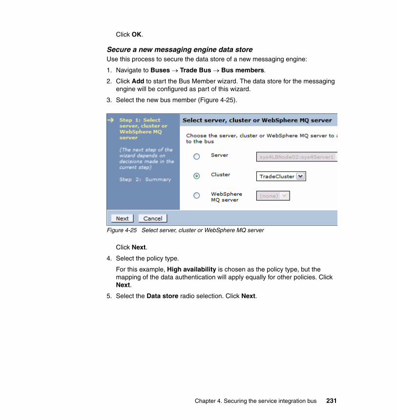
Click OK.
Secure a new messaging engine data store Use this process to secure the data store of a new messaging engine:
1. Navigate to Buses → Trade Bus → Bus members.
2. Click Add to start the Bus Member wizard. The data store for the messaging engine will be configured as part of this wizard.
3. Select the new bus member (Figure 4-25).
Figure 4-25 Select server, cluster or WebSphere MQ server
Click Next.
4. Select the policy type.
For this example, High availability is chosen as the policy type, but the mapping of the data authentication will apply equally for other policies. Click Next.
5. Select the Data store radio selection. Click Next.
Chapter 4. Securing the service integration bus 231

6. Notice that the summary table of the messaging engine configuration indicates that the message store is not configured. Select the messaging engine link (TradeCluster-000-TradeBus) to configure the message store (Figure 4-26).
Figure 4-26 Configure messaging engines
7. Specify the data store properties (Figure 4-27).
Figure 4-27 Specify data store properties
232 WebSphere Application Server V7 Messaging Administration Guide

The data store properties are:
– Data source JNDI name: jdbc/trade-me-ds (Note that this data source was created as part of earlier environment setup).
– Schema name: IBMWSSIB.
– Authentication alias: Select the previously created authentication alias.
– Create tables: Selected.
Click Next.
8. Notice that on return to the Configure message engines panel, the message store now indicates that it is configured (Figure 4-27 on page 232).
Figure 4-28 Configure messaging engines
Click Next.
9. The next panel allows you to adjust heap sizes. No adjustments were done for this exercise. Click Next.
10.Review summary information and click Finish.
11.Save the configuration.
Secure an existing messaging engine data store Use this process to secure the data store of a new messaging engine:
1. Navigate to Buses → Trade Bus → Bus members. Click the bus member name to open the configuration page.
2. Click Messaging engines in the Additional properties section. Then click the messaging engine name to open its configuration page.
3. Click Message store in the Additional properties section.
Chapter 4. Securing the service integration bus 233

4. Select the authentication alias from the drop-down list.
5. Click OK and save your changes.
Configure data store alias using wsadminThe same set of steps can also be achieved using the wsadmin and scripting environment. Example 4-6 shows the commands that could be executed to configure the bus members and data store for the messaging engine. These commands use the jython scripting language and were executed using wsadmin.
Example 4-6 Add member
AdminTask.addSIBusMember('[-bus "Trade Bus" -cluster TradeCluster -enableAssistance true -policyName HA -dataStore -createDefaultDatasource false -datasourceJndiName jdbc/trade-me-ds -authAlias sys2CellManager01/trade-me-alias -createTables true -schemaName IBMWSSIB ]')
If the bus security is enabled after a messaging engine is already configured, this does not secure the data store. Example 4-7 shows the scripting steps to enable security on an existing data store.
Example 4-7 Secure existing data store
engines = AdminTask.listSIBEngines('[-bus ExampleBus]')datastore = AdminConfig.list('SIBDatastore', engines)AdminConfig.modify(datastore, [["authAlias", “sys2CellManager01/BusClusterDataAlias”]])
4.5 Connecting to a secure bus
Connecting a client to a bus is a two-step process, with each step executing authentication controls and authorization controls.
When a client connects to the bus it must provide the authentication details. The user ID that is provided should be made a member of a group that is in the connector role or made a member of the connector role.
4.5.1 Configuring the connector role using administrative console
To configure the connector roles for the bus add the appropriate user/group to the role.
234 WebSphere Application Server V7 Messaging Administration Guide

Referring to the directory information tree shown in Figure 4-4 on page 208, the group group13 will be made a member of the connector role in this example.
1. Open the security configuration for the bus and select the Users and groups in the bus connector role link in the Authorization policy section.
2. Click New.
3. Enter the group search parameters (Figure 4-29).
Figure 4-29 Search for Users or Groups
Chapter 4. Securing the service integration bus 235

4. Select the groups that should be mapped to the authorization roles (Figure 4-30).
Figure 4-30 Select Users or Groups
Click Next.
5. Click Finish.
236 WebSphere Application Server V7 Messaging Administration Guide

6. The new group is now added in the connector role (Figure 4-31). According to the directory information tree, this means that uid1 and uid3 are permitted to connect to the bus.
Figure 4-31 Users and groups in the bus connector role
7. Save the configuration.
4.5.2 Configure the connector role using wsadmin
The same set of steps can be equally achieved using the wsadmin and scripting environment. Example 4-8 shows the commands that could be executed to configure the example group group13 in the connector role on the bus. These commands use the jython scripting language and were executed using wsadmin in an interactive mode.
Example 4-8 Modify connector role groups
AdminTask.addGroupToBusConnectorRole('[-group cn=group13,ou=unit1,o=ibm,c=us -uniqueName cn=group13,ou=unit1,o=ibm,c=us -bus "Trade Bus"]')
4.6 Configuring authorization on queue destinations
Note: This example does not demonstrate the creation of queue destination on the bus, but focuses only on the setting of authorization roles on the destination.
Chapter 4. Securing the service integration bus 237
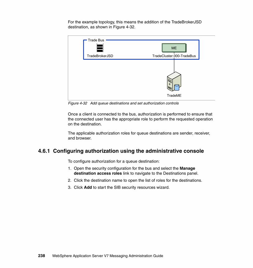
For the example topology, this means the addition of the TradeBrokerJSD destination, as shown in Figure 4-32.
Figure 4-32 Add queue destinations and set authorization controls
Once a client is connected to the bus, authorization is performed to ensure that the connected user has the appropriate role to perform the requested operation on the destination.
The applicable authorization roles for queue destinations are sender, receiver, and browser.
4.6.1 Configuring authorization using the administrative console
To configure authorization for a queue destination:
1. Open the security configuration for the bus and select the Manage destination access roles link to navigate to the Destinations panel.
2. Click the destination name to open the list of roles for the destinations.
3. Click Add to start the SIB security resources wizard.
TradeBrokerJSD
Trade Bus
TradeME
ME
TradeCluster.000-TradeBus
238 WebSphere Application Server V7 Messaging Administration Guide

4. Enter the group search parameters (Figure 4-33).
Figure 4-33 Search for Users or Groups
Click Next.
Chapter 4. Securing the service integration bus 239
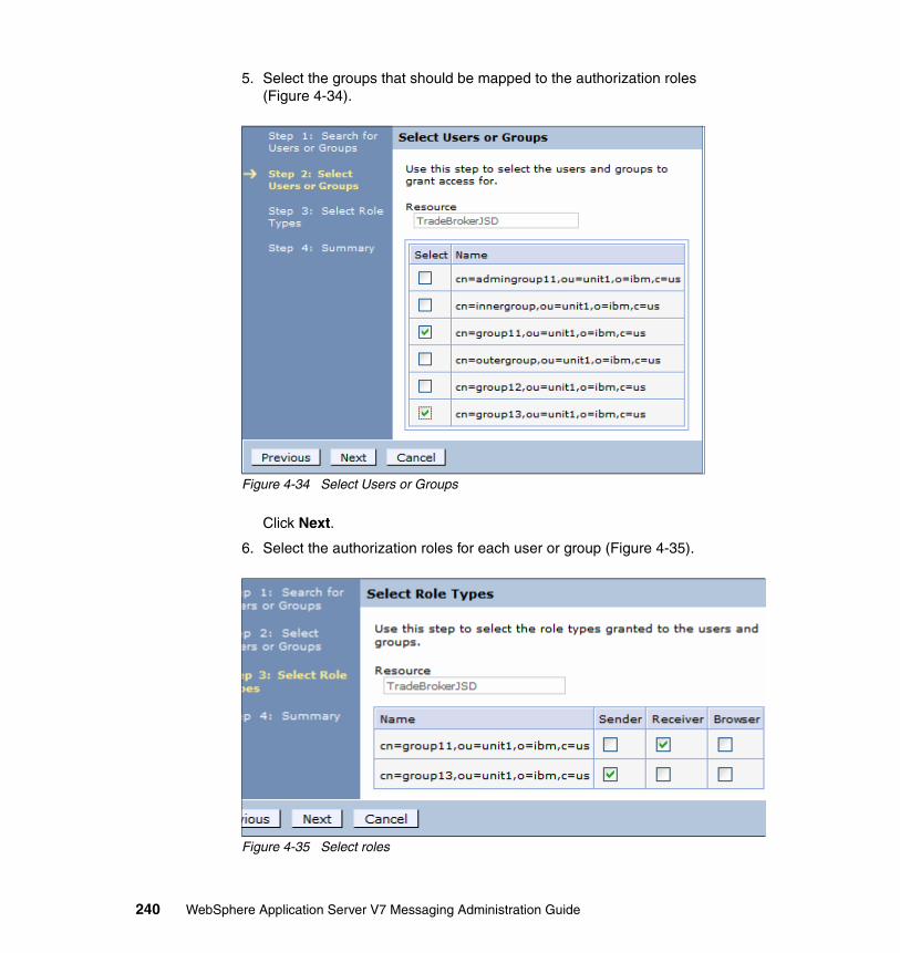
5. Select the groups that should be mapped to the authorization roles (Figure 4-34).
Figure 4-34 Select Users or Groups
Click Next.
6. Select the authorization roles for each user or group (Figure 4-35).
Figure 4-35 Select roles
240 WebSphere Application Server V7 Messaging Administration Guide

Check the sender role for group13 and receiver roles for group11.
Click Next.
7. Click Finish on the summary panel.
8. Save the configuration. The results are shown in Figure 4-36.
Figure 4-36 TradeBokerJSD roles
Figure 4-36 also shows that in addition to the roles specified explicitly here, this destination inherits the default roles. Note that you can also change roles from this panel.
Tip: In Figure 4-2 on page 206, the applicable roles for each destination type are listed. It can be observed in Figure 4-35 on page 240 that only applicable roles for the destination type are shown in the security wizard.
Note: Referring back to the directory information tree in Figure 4-4 on page 208, this role mapping would allow group11 (uid1 and uid2) to receive messages, while group13 (uid1 and uid3) can send messages to this destination.
Chapter 4. Securing the service integration bus 241
4.6.2 Configuring authorization using wsadmin
The same set of steps also can be achieved using the wsadmin and scripting environment. The following example shows the commands that could be executed to configure the example groups group13 in the sender role and group11 in the receiver role for the TradeBrokerJSD destination. These commands use the jython scripting language and were executed using wsadmin in an interactive mode.
Add a group to the sender role (Example 4-9).
Example 4-9 Add group to sender role
AdminTask.addGroupToDestinationRole('[-group cn=group11,ou=unit1,o=ibm,c=us -uniqueName cn=group11,ou=unit1,o=ibm,c=us -type Queue -bus "Trade Bus" -destination TradeBrokerJSD -role Receiver]')
Troubleshooting tip: Group11 consists of uid1 and uid2. If the configuration as shown so far is left unchanged, message-driven beans configured using an alias with uid2 would not ever successfully receive a message. Why is it that uid2, even though it is a member of group11, is not able to receive messages?
The answer is that group11 is not authorized in the connector role. User uid2 would never get as far as authorizing to receive a message. User uid2 would be stopped in its attempt to connect to the bus. For all of group11 to be able to receive messages, group11 must be in the connector role, or each user must be in a second group that has the connector role (for example, group13). User uid1 would be successful in connecting because it has authorization permissions as a member of group13.
As the example progresses assume that group11 has been added to the connector role.
Tip: If you decide that the destination should not inherit the default roles, uncheck the Inherit from default check box.
242 WebSphere Application Server V7 Messaging Administration Guide

Add the group to the receiver role (Example 4-10).
Example 4-10 Add group to receiver role
AdminTask.addGroupToDestinationRole('[-group cn=group13,ou=unit1,o=ibm,c=us -uniqueName cn=group13,ou=unit1,o=ibm,c=us -type Queue -bus "Trade Bus" -destination TradeBrokerJSD -role Sender]')
4.7 Configuring authorization on temp destinations
A temporary destination only exists while an application is using it. For example, if an application creates a temporary JMS queue for use with the default messaging provider, the SIB service automatically creates a temporary queue destination on the bus. Temporary destinations can be of queue or topic type and exist for a finite period of time while consumed by an application. For more information about temporary destinations see:
http://publib.boulder.ibm.com/infocenter/wasinfo/v7r0/topic/com.ibm.websphere.pmc.nd.multiplatform.doc/concepts/cjo0003_.html
Temporary destinations appear in the list of runtime queue and publication points for a messaging engine on the service integration bus, but usually need no administration. However, authorization of temporary destinations must be controlled. This section details the steps for managing access roles on temporary destinations.
When destinations are created, a name unique to the SIB service is assigned to it. The name is a combination of three elements:
� Temporary destination identifier
This is _Q or _T, depending on the destination type.
� A prefix
� A generated unique identifier
Chapter 4. Securing the service integration bus 243

This name combination is shown in Figure 4-37.
Figure 4-37 Temporary names
The type and unique identifiers cannot be modified, but the prefix can be specified on the connection factory. The default prefix value is empty.
To set the prefix, navigate to the connection factory (for example, Resources → JMS → Queue connection factories → TradeBrokerQCF). The prefix can be specified in the Advanced Messaging section. The prefix must be 12 characters or less (Figure 4-38).
Figure 4-38 Set the prefix when using temporary destinations with the bus
The prefix can then be used as an identifier for mapping authorization roles.
Note: The temporary destination prefix is provided by the JMS client. As a result, if security is desired on temporary destination prefixes you should ensure that the default creator role has no associated users or groups. If a default creator role is configured, users who have that role can create temporary destinations with any prefix.
The name of an administratively defined queue can also be used for a prefix. The only relationship between a temporary queue and an administratively defined queue is the security policy. As a result, this is unlikely to produce the desired security policy.
Temporary Queue Name
_Q Prefix Generated unique identifier
Temporary Topic Name
_T Prefix Generated unique identifier
244 WebSphere Application Server V7 Messaging Administration Guide
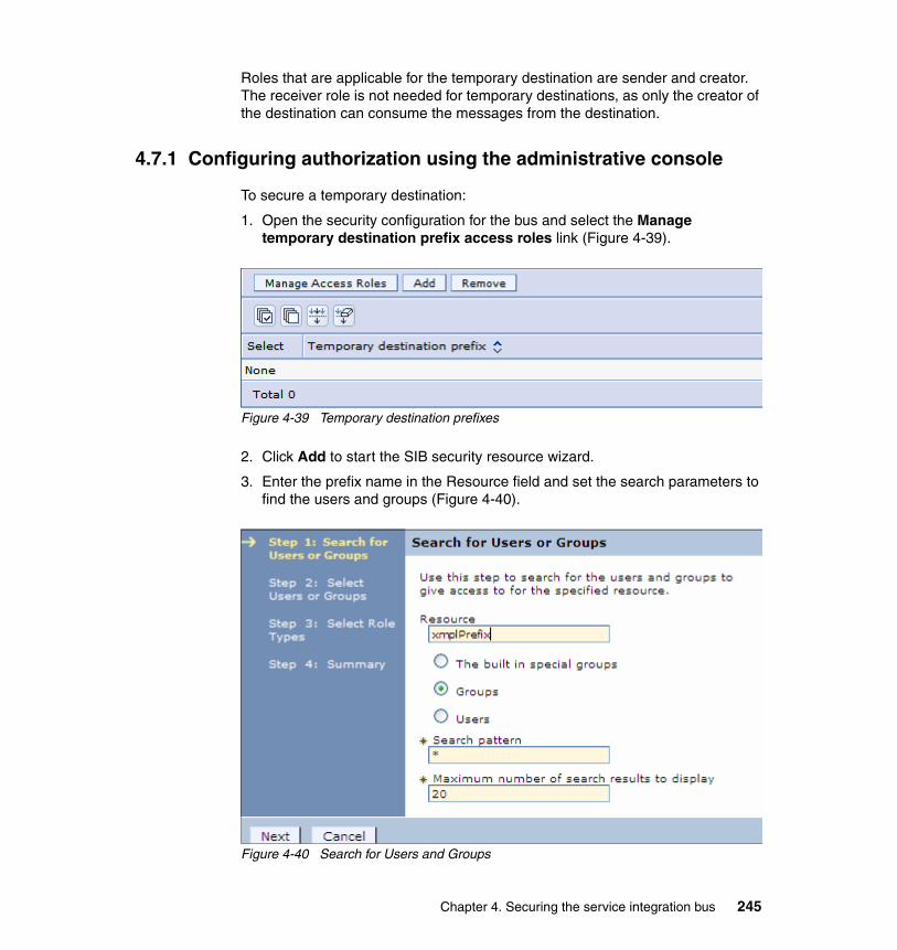
Roles that are applicable for the temporary destination are sender and creator. The receiver role is not needed for temporary destinations, as only the creator of the destination can consume the messages from the destination.
4.7.1 Configuring authorization using the administrative console
To secure a temporary destination:
1. Open the security configuration for the bus and select the Manage temporary destination prefix access roles link (Figure 4-39).
Figure 4-39 Temporary destination prefixes
2. Click Add to start the SIB security resource wizard.
3. Enter the prefix name in the Resource field and set the search parameters to find the users and groups (Figure 4-40).
Figure 4-40 Search for Users and Groups
Chapter 4. Securing the service integration bus 245

The Resource field can be left empty to use the default prefix. Click Next.
4. Select the groups to map to the temporary destination roles that start with the prefix that you specified. For this example group11 and group 13 are used (Figure 4-41).
Figure 4-41 Select Users or Groups
Click Next.
246 WebSphere Application Server V7 Messaging Administration Guide

5. Map the chosen groups to the roles that the group should be authorized to perform for the temporary destination of the specified prefix (Figure 4-42).
Figure 4-42 Select Role Types
Click Next.
In this example, group11 is given the sender role, allowing members of this group to send messages to the temporary destination.
Group13 is given the creator role, allowing members of this group to create the temporary destination and receive messages on the destination.
6. On the summary panel click Finish.
7. Save the configuration.
Chapter 4. Securing the service integration bus 247

To manage these roles later or add new users to the roles, select the check box for the prefix on the Temporary Destinations prefixes panel and click Manage roles (Figure 4-43).
Figure 4-43 Temporary destination prefixes
This navigates to the Temporary destination prefix access roles panel, shown in Figure 4-44.
Figure 4-44 Temporary destination prefix access roles
4.7.2 Configuring authorization using wsadmin
The same set of steps can be equally achieved using the wsadmin and scripting environment.
The following examples show the commands that could be executed to configure the example groups group13 in the creator role and group11 in the sender role
248 WebSphere Application Server V7 Messaging Administration Guide

for the temporary destination with prefix xmplPrefix. These commands use the jython scripting language and were executed using wsadmin in an interactive mode.
� Adding a group to the creator role is shown in Example 4-11.
Example 4-11 Add group to creator role for temporary queue
AdminTask.addGroupToDestinationRole('[-group cn=group13,ou=unit1,o=ibm,c=us -uniqueName cn=group13,ou=unit1,o=ibm,c=us -type Queue -bus "Trade Bus" -destination xmplPrefix -role Creator]')
� Adding a group to the sender role is shown in Example 4-12.
Example 4-12 Add group to sender role for temporary queue
AdminTask.addGroupToDestinationRole('[-group cn=group11,ou=unit1,o=ibm,c=us -uniqueName cn=group11,ou=unit1,o=ibm,c=us -type Queue -bus "Trade Bus" -destination xmplPrefix -role Sender]')
Chapter 4. Securing the service integration bus 249
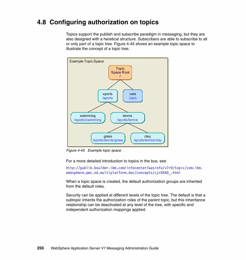
4.8 Configuring authorization on topics
Topics support the publish and subscribe paradigm in messaging, but they are also designed with a heretical structure. Subscribers are able to subscribe to all or only part of a topic tree. Figure 4-45 shows an example topic space to illustrate the concept of a topic tree.
Figure 4-45 Example topic space
For a more detailed introduction to topics in the bus, see:
http://publib.boulder.ibm.com/infocenter/wasinfo/v7r0/topic/com.ibm.websphere.pmc.nd.multiplatform.doc/concepts/cjr0440_.html
When a topic space is created, the default authorization groups are inherited from the default roles.
Security can be applied at different levels of the topic tree. The default is that a subtopic inherits the authorization roles of the parent topic, but this inheritance relationship can be deactivated at any level of the tree, with specific and independent authorization mappings applied.
Example.Topic.Space
TopicSpace Root
/
sports/sports
cars/cars
swimming/sports/swimming
tennis/sports/tennis
grass/sports/tennis/grass
clay/sports/tennis/clay
250 WebSphere Application Server V7 Messaging Administration Guide

The following example demonstrates associating authorization roles at a variety of points in the topic hierarchy.
The applicable roles for a topic destination are sender and receiver.
4.8.1 Configuring authorization using the administrative console
This section shows how to add a role to the topic space root, then to a sub-hierarchy of the root. The trade example only utilizes a single target topic. To allow this section to explore other security features of topic spaces this section deviates from the trade example. For these examples a bus called ExampleBus is used.
Adding roles at the topic space rootThis section shows how to add authorization for the root level of the topic hierarchy. In this example, the receiver role will be given to group12. This will give the members of the group (currently, only uid2) receiver authorization for all messages posted to the topic hierarchy (Figure 4-46).
Figure 4-46 Receiver role on root
Tip: Think about what happens if topic authorizations are created at the topic space root. The topic space is the only administration object. Topics are created when a subscription becomes active. Thus, authorization roles at the topic root level provide the default authorization levels.
It may be desirable to maintain finer grained authorization controls by asserting authorization roles in one tier removed from the root or the topic tree.
Note: When configuring security for topics, a client must have the sender (or receiver) role both for the TopicSpace destination and for the topic being accessed.
Example.Topic.Space
TopicSpace Root
/root:receiver
ou=group12,ou=unit1,o=ibm,c=us
Chapter 4. Securing the service integration bus 251
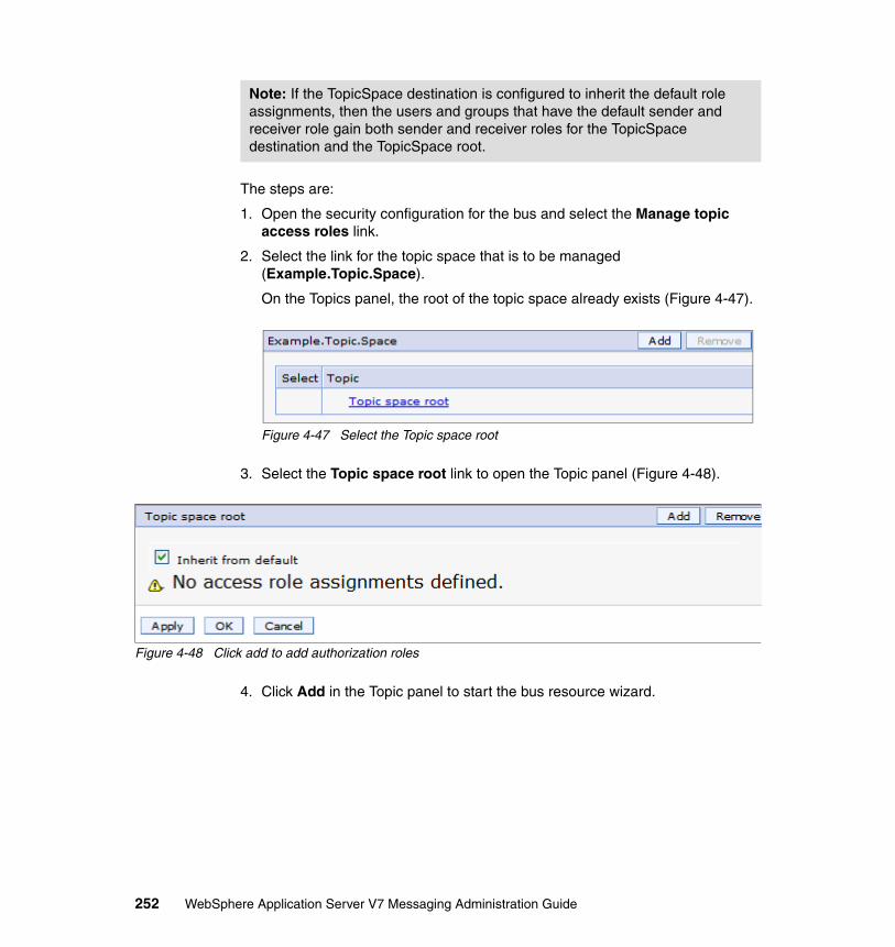
The steps are:
1. Open the security configuration for the bus and select the Manage topic access roles link.
2. Select the link for the topic space that is to be managed (Example.Topic.Space).
On the Topics panel, the root of the topic space already exists (Figure 4-47).
Figure 4-47 Select the Topic space root
3. Select the Topic space root link to open the Topic panel (Figure 4-48).
Figure 4-48 Click add to add authorization roles
4. Click Add in the Topic panel to start the bus resource wizard.
Note: If the TopicSpace destination is configured to inherit the default role assignments, then the users and groups that have the default sender and receiver role gain both sender and receiver roles for the TopicSpace destination and the TopicSpace root.
252 WebSphere Application Server V7 Messaging Administration Guide

5. Set the search parameters for users and groups, then click Next (Figure 4-49).
Figure 4-49 Search for Users or Groups
Chapter 4. Securing the service integration bus 253

6. Select the groups. In this example group12 will be mapped to the receiver authorization role, so group12 is selected (Figure 4-50).
Figure 4-50 Select Users or Groups
Click Next.
7. Select the receiver role (Figure 4-51).
Figure 4-51 Select Role Types
254 WebSphere Application Server V7 Messaging Administration Guide

Click Next.
8. Click Finish on the summary panel.
9. Save the configuration.
The addition of the receiver role to the root topic space is now complete (Figure 4-52).
Figure 4-52 Group added to receiver role at the root of the topic space
Adding roles at sub hierarchyIn this example a sender group will be added to the second level of the topic hierarchy (sports). The process uses the same wizard as in the previous example.
In this example group13 will be added to the sender role on the sports group, as shown in Figure 4-53. Assuming no additional role mappings in sub topics and that sub topics are configured to inherit their access roles, users from group12 would be able to receive messages as inherited from the topic space root and users from grpoup13 could send messages to sports and its sub topics.
Figure 4-53 Sender role on /sports
Example.Topic.Space
root:receiverou=group12,ou=unit1,o=ibm,c=us
sports/sports
cars/cars
TopicSpace Root
/
Chapter 4. Securing the service integration bus 255

The steps are:
1. Select Buses → ExampleBus → Security → Manage topic access roles → Example.Topic.Space.
2. Click the Topic space root link and click Add.
3. Enter the topic name (sports) in the Resource field and the user/group search criteria (Figure 4-54).
Figure 4-54 Search for Users and Groups
Click Next.
4. Select the group (group13) and click Next.
256 WebSphere Application Server V7 Messaging Administration Guide

5. Select the sender role (Figure 4-55) and click Next.
Figure 4-55 Select Role Types
6. Click Finish and save the configuration. The results are shown in Figure 4-56.
Figure 4-56 Sports topic added to visible topic authorizations
Chapter 4. Securing the service integration bus 257

7. To see the new access roles for the sports topic, click the sports link on the Topics panel (Figure 4-56 on page 257).
This shows the group role mapping (Figure 4-57). The arrow pointing straight up indicates that the role relationship is inherited, in this case from the parent.
Figure 4-57 Topic authorization role mappings
258 WebSphere Application Server V7 Messaging Administration Guide

Controlling topic authorization inheritanceTopics inherit authorization role access by default. This inheritance can be controlled. This example illustrates how to limit inheritance of the role authorization that is specified for the sender role at the /sports level. Figure 4-58 illustrates the authorization mapping.
Figure 4-58 Expanded topic authorization tree
Note that you do not need to have created sports/tennis beforehand. You can create sports/tennis/clay directly. You only need to define the points in the tree that you care about controlling. The parent hierarchy is inferred from the points that have security applied.
Example.Topic.Space
root:receiverou=group12,ou=unit1,o=ibm,c=us
sports/sports
cars/cars
swimming/sports/swimming
tennis/sports/tennis
grass/sports/tennis/grass
clay/sports/tennis/clay
TopicSpace Root
/
/sports/tennis/clay:senderou=group12,ou=unit1,o=ibm,c=us
Do not inherit sender
/sports:senderou=group13,ou=unit1,o=ibm,c=us
Chapter 4. Securing the service integration bus 259
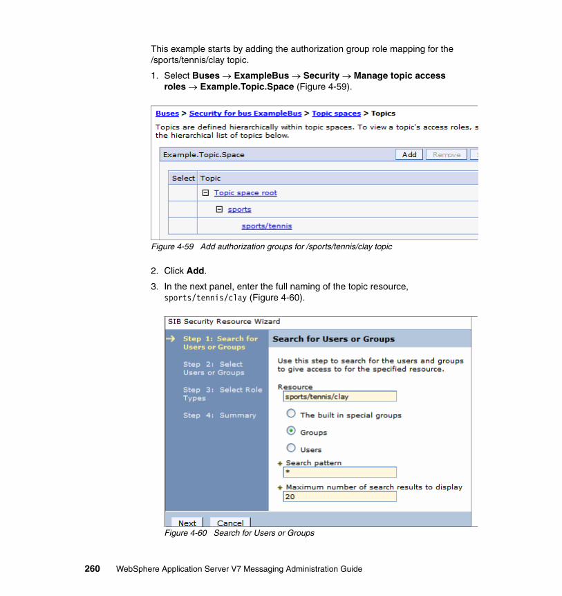
This example starts by adding the authorization group role mapping for the /sports/tennis/clay topic.
1. Select Buses → ExampleBus → Security → Manage topic access roles → Example.Topic.Space (Figure 4-59).
Figure 4-59 Add authorization groups for /sports/tennis/clay topic
2. Click Add.
3. In the next panel, enter the full naming of the topic resource, sports/tennis/clay (Figure 4-60).
Figure 4-60 Search for Users or Groups
260 WebSphere Application Server V7 Messaging Administration Guide
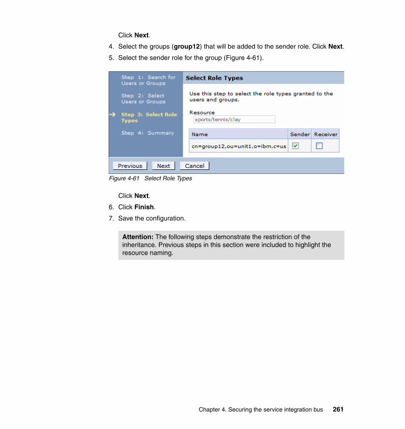
Click Next.
4. Select the groups (group12) that will be added to the sender role. Click Next.
5. Select the sender role for the group (Figure 4-61).
Figure 4-61 Select Role Types
Click Next.
6. Click Finish.
7. Save the configuration.
Attention: The following steps demonstrate the restriction of the inheritance. Previous steps in this section were included to highlight the resource naming.
Chapter 4. Securing the service integration bus 261

8. Select Buses → ExampleBus → Security → Manage topic access roles → Example.Topic.Space. Click the sports/tennis/clay link to display the access roles of the topic (Figure 4-56 on page 257).
Figure 4-62 Roles with inheritance
9. Uncheck the Inherit sender role from parent.
10.Click Apply, then save the configuration.
Note: The inheritance does not have fine-grained controls. All parent topic sender roles or all topic receiver roles are inherited. When inheritance is turned off all parent topics are removed from the access roles.
This means that once the sender role is no longer inherited group13 will not have send access on sports/tennis/clay.
262 WebSphere Application Server V7 Messaging Administration Guide
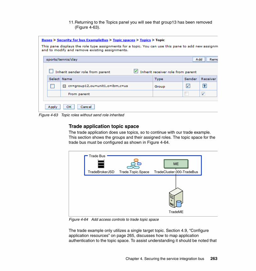
11.Returning to the Topics panel you will see that group13 has been removed (Figure 4-63).
Figure 4-63 Topic roles without send role inherited
Trade application topic spaceThe trade application does use topics, so to continue with our trade example. This section shows the groups and their assigned roles. The topic space for the trade bus must be configured as shown in Figure 4-64.
Figure 4-64 Add access controls to trade topic space
The trade example only utilizes a single target topic. Section 4.9, “Configure application resources” on page 265, discusses how to map application authentication to the topic space. To assist understanding it should be noted that
TradeBrokerJSD Trade.Topic.Space
Trade Bus
TradeME
ME
TradeCluster.000-TradeBus
Chapter 4. Securing the service integration bus 263

the topic space was configured with group13 in the sender role and group11 in the receiver role. These access roles are configured at the topic space root, as shown in Figure 4-65, using the approach described in “Adding roles at the topic space root” on page 251.
Figure 4-65 Trade bus topic space root
4.8.2 Configuring authorization using wsadmin
The same set of steps also can be achieved using the wsadmin and scripting environment.
The following examples show the commands that could be executed to configure the topic authorization role mapping specified in Figure 4-58 on page 259. These commands use the jython scripting language and were executed using wsadmin in an interactive mode.
� Add a group to the receiver role for the topic space root (Example 4-13).
Example 4-13 Add group to the sender role at the topic space root
AdminTask.addGroupToTopicSpaceRootRole('[-group cn=group12,ou=unit1,o=ibm,c=us -uniqueName cn=group12,ou=unit1,o=ibm,c=us -bus ExampleBus -topicSpace Example.Topic.Space -role Receiver]')
� Add a group to the sender roles in the topic hierarchy (Example 4-14).
Example 4-14 Add group to sender roles in topic hierarchy
AdminTask.addGroupToTopicRole('[-group cn=group13,ou=unit1,o=ibm,c=us -uniqueName cn=group13,ou=unit1,o=ibm,c=us -bus ExampleBus -topicSpace Example.Topic.Space -topic sports -role Sender]')
264 WebSphere Application Server V7 Messaging Administration Guide

AdminTask.addGroupToTopicRole('[-group cn=group12,ou=unit1,o=ibm,c=us -uniqueName cn=group12,ou=unit1,o=ibm,c=us -bus ExampleBus -topicSpace Example.Topic.Space -topic sports/tennis/clay -role Sender]')
� Remove the sender inheritance from the topic (Example 4-15).
Example 4-15 Remove inheritance of sender role
AdminTask.setInheritSenderForTopic('[-bus ExampleBus -topicSpace Example.Topic.Space -topic sports/tennis/clay -inherit false]')
4.9 Configure application resources
Both the clients and the destinations of the application must be able to connect to the bus, so in addition to needing the connector role to authorize the connection, user credentials must be supplied by the application when connecting to the bus. When configuring application resources for secure connectivity to the bus, the resources that will facilitate a secure connection are:
� Queue connection factories (TradeBrokerQCF)� Topic connection factories (TradeStreamerTCF)� Queue activation specifications (TradeBrokerAS) and � Topic activation specifications (TradeStreamerAS)
The following examples show how to specify the authentication credentials to be used.
Container-managed authentication aliases can either be configured as part of bindings of an application when it is installed, or as part of the resource definition (for example, on the connection factory configuration).
Figure 4-66 shows the addition of the application resources for the trade application example. The bus destinations have been created. Securing the application resources is the final step in configuring the environment.
Chapter 4. Securing the service integration bus 265

Figure 4-66 Application resources added
Note: Clients running outside of an application server (for instance, in the client container) can make use of both user ID/password and certificate-based authentication using client SSL authentication.
Cell
Node Node
Application Server
Trade
Node Agent
LDAP TradeDB
TradeStreamerTopic TradeStreamerTCF TradeStreamerAS
TradeBrokerJSD Trade.Topic.Space
Trade Bus
TradeBrokerQCF TradeBrokerAS
Node
DeploymentManager
TradeBrokerQueue
TradeME
Application Server
Trade
Node Agent
Trade Cluster
ME
TradeCluster.000-TradeBus
266 WebSphere Application Server V7 Messaging Administration Guide
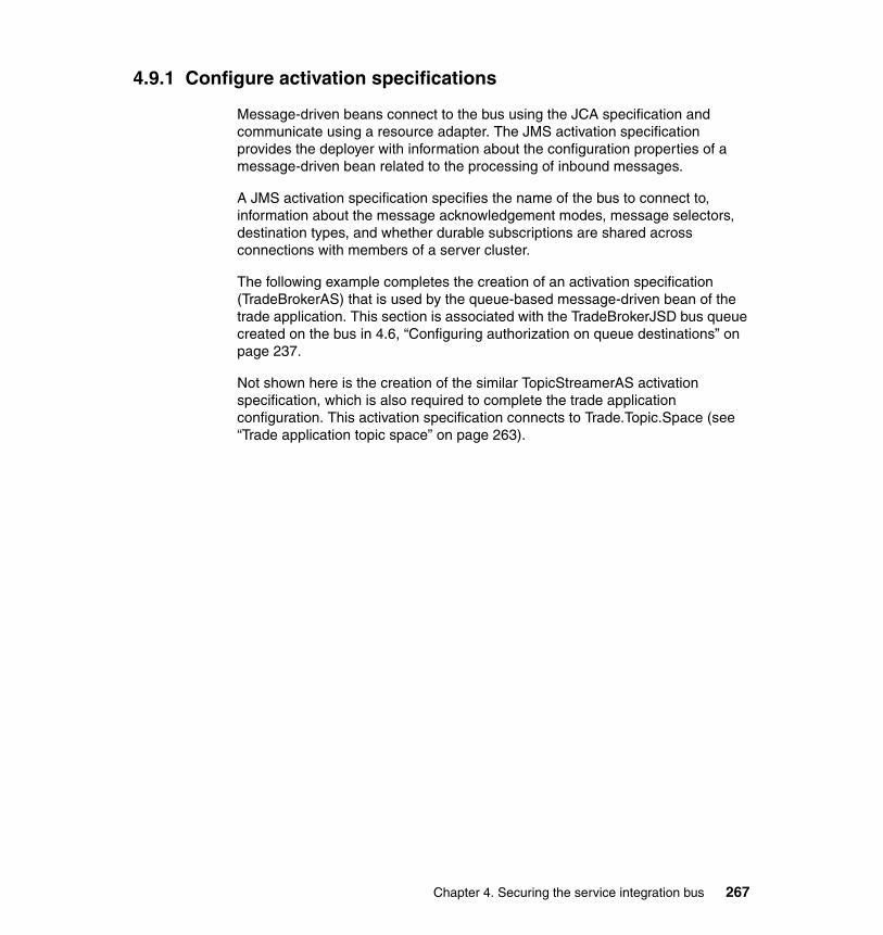
4.9.1 Configure activation specifications
Message-driven beans connect to the bus using the JCA specification and communicate using a resource adapter. The JMS activation specification provides the deployer with information about the configuration properties of a message-driven bean related to the processing of inbound messages.
A JMS activation specification specifies the name of the bus to connect to, information about the message acknowledgement modes, message selectors, destination types, and whether durable subscriptions are shared across connections with members of a server cluster.
The following example completes the creation of an activation specification (TradeBrokerAS) that is used by the queue-based message-driven bean of the trade application. This section is associated with the TradeBrokerJSD bus queue created on the bus in 4.6, “Configuring authorization on queue destinations” on page 237.
Not shown here is the creation of the similar TopicStreamerAS activation specification, which is also required to complete the trade application configuration. This activation specification connects to Trade.Topic.Space (see “Trade application topic space” on page 263).
Chapter 4. Securing the service integration bus 267

Configure authentication aliasThe message-driven bean must have an authentication alias to authenticate and authorize the connection to the bus. For this example the user uid1 is used.
1. Open the security configuration for the bus and select the JAAS- J2C authentication data link.
2. Click New to create the new alias, as shown in Figure 4-24 on page 230.
Figure 4-67 New authentication alias
Configure the activation specification
1. From the resources menu navigate to the Resources → JMS → Activation Specifications panel.
2. Select the desired scope for the resource (Cluster=TradeCluster).
3. Click New.
Notes about the example: The Resources → JMS → Activation Specification → New panel is a large scrolling panel. The configured elements used in this example will be shown using different panel shots of smaller sections of the panel. Sections not shown were not modified from the defaults.
The purpose here is to configure security with the bus. Thus, where non-security-related defaults are provided they are used. This does not imply that these defaults are appropriate for your environment.
268 WebSphere Application Server V7 Messaging Administration Guide

4. On the Select JMS provider panel select the Default messaging provider radio selection. Click OK.
5. Complete the Activation Specification panel:
a. Complete the Administration section as shown in Figure 4-68.
Figure 4-68 Administration
b. Complete the Destination section, as shown in Figure 4-69.
Figure 4-69 Destination
Chapter 4. Securing the service integration bus 269

c. Complete the Security settings section, as shown in Figure 4-70.
Figure 4-70 Security settings
The authentication alias will be used when the MDB connects to the bus. The user must be in a group configured in the connector role and the receiver role in order for the MDB to receive messages.
Tip: The authentication alias can be defined in one of two places:
� In the activation specification
� In the application configuration for the message-driven bean when configuring the MDS bindings
Configuring at the application level provides finer grained controls. In such a scenario if a user were to be removed from the authorization group their user would no longer be authorized. This could occur without impact to other subscribers and without a need to change the activation specification alias.
Defining the alias as an activation specification is a coarser grained authorization model.
An example of a reason to define the authentication alias at the application level is if the activation specification was a topic destination. Different subscribers can be configured with different authentication IDs.
270 WebSphere Application Server V7 Messaging Administration Guide

d. Click OK and save the configuration. The results are shown in Figure 4-71.
Figure 4-71 Activation specification complete
Note also that a similar activation specification was completed for the topic activation specification TradeStreamerAS, but no authentication alias was added. This will be completed in 4.9.3, “Configuring application resources during application install” on page 275.
Attention: It is important to remember that the listeners used by the message-driven bean are bound at deployment time. Any configuration for the JCA binding that exists in the application will take precedence over the administration objects. For example, an authentication alias defined in the application resource binding will be used instead of an authentication alias defined on the activation specification administration object. See the information center for additional information:
http://publib.boulder.ibm.com/infocenter/wasinfo/v7r0/topic/com.ibm.websphere.nd.multiplatform.doc/info/ae/ae/cj2c_as.html
Always check or explicitly set the message listener bindings when installing an application.
Chapter 4. Securing the service integration bus 271

4.9.2 Configuring security on connection factories
The steps for configuring security for a connection factory are similar to those described for the activation specification. Similar issues also apply when considering whether to associate a component-managed authentication alias with the connection factory. The connection factory is a resource, and setting the component-managed authentication alias as a property of the connection factory means that all applications that have JNDI visibility of the connection factory can use the connection factory to connect with and authorize the bus.
For finer grained controls do not set an alias on the connection factory. Instead, associate the authentication alias to the connection factory via the resource reference when installing the application (see “Java EE JMS client resource reference binding” on page 278).
For this example the queue connection factory for the trade application TradeBrokerQCF will be created.
The topic connection factory is not shown here but is very similar.
1. From the resources menu navigate to the Resources → JMS → Connection Factories panel.
2. Select the desired scope for the resource (Cluster=TradeCluster) and click New.
3. Select the Default messaging provider and click OK.
Notes about the example: The Resources → JMS → Queue Connection Factories → Default messaging Provider → New panel is a large scrolling panel. The configured elements used in this example will be shown using different panel images of smaller sections of the panel. Sections not shown were not modified from the defaults.
The purpose here is to configure security with the bus. Thus, where non-security-related defaults are provided they are used. This does not imply that these defaults are appropriate for your environment.
272 WebSphere Application Server V7 Messaging Administration Guide

4. Complete the connection factory panel as shown in Figure 4-72.
Figure 4-72 Administration
a. Complete the Connection section, as shown in Figure 4-73.
Figure 4-73 Connection
b. Complete the Security settings section, as shown in Figure 4-74.
Figure 4-74 Security settings
Chapter 4. Securing the service integration bus 273

The authentication alias will be used when the connection factory connects to the bus. The user must be in a group configured in the connector role in order for the factory to connect to the bus.
c. Click OK and save the configuration. The results are shown in Figure 4-75.
Figure 4-75 Created queue connection factory
Note also that a similar connection factory was completed for the topic factory TradeStreamerTCF, but no authentication alias was added. This will be demonstrated in 4.9.3, “Configuring application resources during application install” on page 275.
To complete the picture, the JMS queue and JMS topic for the trade application must be configured. We do not show this here, as there is no element related to the securing of the communication in this step, but these resources are required before installing the application.
Note: It is advisable (although not always necessary) to specify an authentication alias for XA recovery.
During transactional recovery, if a bus has been secured, the transaction manager must have credentials when connecting to a secured bus. If the messaging engine being recovered is a V7 messaging engine in the same cell, then the server can use a special LTPA token for recovery. If the messaging engine is in a remote cell or running on a v6.x node then this is not possible and the authentication alias for XA recovery must be specified. It is a good practice to specify this, rather than relying on the LTPA fallback authentication scheme.
274 WebSphere Application Server V7 Messaging Administration Guide

4.9.3 Configuring application resources during application install
In the following sections, two specific steps in the application installation wizard are used to illustrate how to apply security for components that connect to the bus. Only steps 5 and 6 (shown in Figure 4-76) are discussed.
Figure 4-76 Installation steps for a messaging applciation
Tip: The configurations that will be discussed in the following section can be completed before the enterprise application archive (EAR) is created. But because the settings defined in the applicaiton will always take precedence over environment settings at different scopes, you should always confirm the settings during installation.
Chapter 4. Securing the service integration bus 275
Binding activation specifications to message-driven beansThe bindings for message-driven beans are configured in the bind listeners for message-driven beans step:
1. The wizard panel for this step lists the message-driven beans in the application.
2. To map the authentication alias to the message-driven bean, check the box to the left of the message-driven bean entry (TradeStreamerMDB in this example).
3. Expand the Apply multiple settings tree view and select the ActivationSpec authentication alias. Then click Apply (Figure 4-77).
276 WebSphere Application Server V7 Messaging Administration Guide

Figure 4-77 Add authentication alias
Chapter 4. Securing the service integration bus 277

Once completed, the alias will be used when connecting with the bus. The completed configuration is shown in Figure 4-78.
Figure 4-78 Completed message-driven bean configuration
This process can be repeated as many times as needed to associate different aliases to the different message-driven beans in the panel.
Java EE JMS client resource reference bindingThe JMS connection factory makes the connection to the bus. When configuring Java EE JMS clients, we recommended that you provide a container-managed authentication alias as part of the resource reference when installing the application:
http://publib.boulder.ibm.com/infocenter/wasinfo/v7r0/topic/com.ibm.websphere.nd.multiplatform.doc/info/ae/ae/csec_j2csecurity.html
A resource reference decouples the code from the environment resources. The application developer does not need to know the names of the JNDI resources at the time that the application is written, as they are resolved to real JNDI resources by the administrator when the application is deployed. The environment resources are resources specific to the environment in which the application is running (the WebSphere topology).
278 WebSphere Application Server V7 Messaging Administration Guide

Figure 4-79 shows a simple illustration of the role of resource references.
Figure 4-79 Resource references role
The association of the resource reference should be completed as part of the application installation process. When you use the application installation wizard, the resource reference mapping is completed on the Map resource references to resources step in the installation. This panel is shown in Figure 4-80 on page 280. The authentication alias is mapped to the connection factory resource reference.
1. When first navigating to the Map resource reference to resources panel the different references and resource types are listed as shown in Figure 4-80 on page 280. For this example the focus is on configuring resource references for the topic connection factory.
Authentication Alias
JNDI JNDI
Application code thatrequires environmentresource uses a localname in the code.
Environment resourcesare configured byadministrators with a JNDIname used by theenvironment.
A resource reference bridgesthe application resourcename and the environmentresource name and allows foradditional properties such assecurity to be configured.
Chapter 4. Securing the service integration bus 279
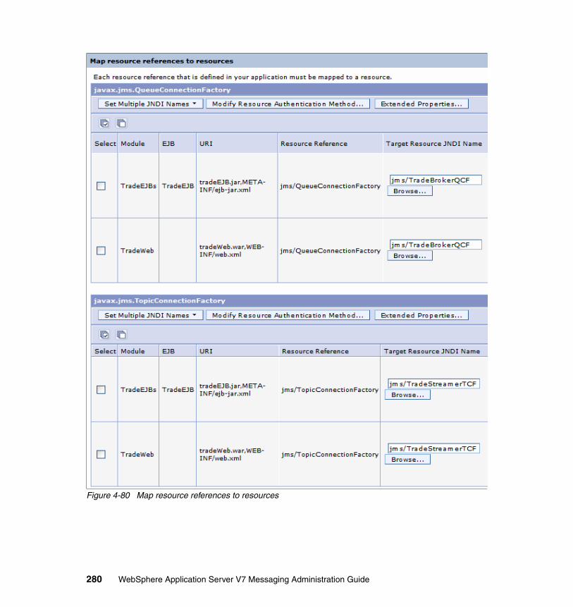
Figure 4-80 Map resource references to resources
280 WebSphere Application Server V7 Messaging Administration Guide

2. Map the authentication alias to the container-managed login configuration as shown in Figure 4-81:
a. Check the resource references for the topic connection factory.
b. Click the Modify Resource Authentication Method button to show the Specify authentication method sub panel.
c. Select Use default method and choose the authentication alias from the selection list.
d. Click Apply.
Figure 4-81 Authentication alias resource reference mapping
Chapter 4. Securing the service integration bus 281
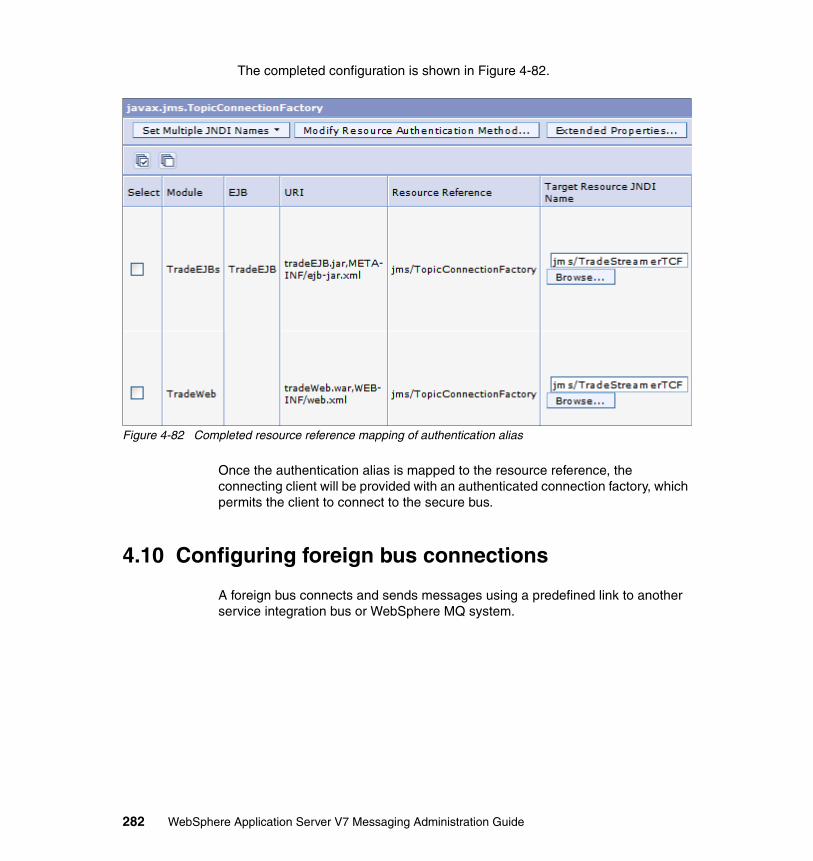
The completed configuration is shown in Figure 4-82.
Figure 4-82 Completed resource reference mapping of authentication alias
Once the authentication alias is mapped to the resource reference, the connecting client will be provided with an authenticated connection factory, which permits the client to connect to the secure bus.
4.10 Configuring foreign bus connections
A foreign bus connects and sends messages using a predefined link to another service integration bus or WebSphere MQ system.
282 WebSphere Application Server V7 Messaging Administration Guide

Figure 4-83 shows a foreign bus connection to another service integration bus being implemented.
Figure 4-83 Foreign bus connections
The following example shows how to create a foreign bus and configure authorization for the local bus to connect to it.
Cell
BusCluster1
Application Server Application Server
MessageEngine
(passive)
Example Bus
BusCluster2
Application Server
MessageEngine
(passive)
Application Server
Example Bus
BusCluster2.000-ExampleBus
MessageEngine
MessageEngine
BusCluster1.000-ExampleBus
example-fb-link
Chapter 4. Securing the service integration bus 283

4.10.1 Configuration using the administrative console
This example consists of two steps:
1. Create a secure foreign bus link.2. Create a foreign destination.
Create a secure foreign bus link In creating the foreign bus link the security considerations include securing the communications and the authentication and authorization of a user in the foreign bus connector role to allow connections.
The foreign bus connection must be established on both sides of the connection to establish the foreign bus link.
In this example, a connection is established between the buses ExampleBus and Example1Bus. Figure 4-84 shows the bus connection that is created (example-fb-link). The buses and messaging engines are already created.
Figure 4-84 Foreign bus components: Create bus connection
Bus Member Bus Member
MessageEngine
example-fb-link
ForeignBus
Connection
MessageEngine
example-fb-link
Foreign Bus
Connection
BusCluster2.000-Example1Bus BusCluster1.000-ExampleBus
ExampleBusExample1Bus
Foreign Bus link SSL
284 WebSphere Application Server V7 Messaging Administration Guide

On the system hosting ExampleBus, do the following:
1. From the service integration menu navigate to Buses → ExampleBus and select the Foreign Bus Connections link in the Topology section of the panel.
2. Click New to start the Foreign bus connection wizard.
3. Select the Direct connection bus connection type and click Next.
4. Select Service integration bus as the foreign bus type and click Next.
5. Choose the message engine that will host the connection (Figure 4-85) and click Next.
Figure 4-85 Local bus details
Chapter 4. Securing the service integration bus 285

Information: If the buses that are connected using a foreign bus link exist in different security domains, It may be necessary to change the incoming message ID so that when access control checks are made, the message is granted the desired permissions.
Setting the inbound user ID will change the SIB Security ID of incoming messages. This identifier is what is used for authorization checking. In our example a common registry and a single security domain are used, so this is not required. For more information see:
http://publib.boulder.ibm.com/infocenter/wasinfo/v7r0/topic/com.ibm.websphere.pmc.nd.multiplatform.doc/tasks/tjr0010_.html
286 WebSphere Application Server V7 Messaging Administration Guide

6. Enter the information that describes the foreign bus (Figure 4-86).
Figure 4-86 Foreign bus details
Chapter 4. Securing the service integration bus 287

In this example the foreign bus is being configured in the same cell. As a result, the foreign bus options are made available for selection from lists. If the foreign bus is in a different cell, the bus name and the message engine names must be explicitly entered in the text fields at the top of the panel.
The service integration bus link name is a vital configuration item on this panel. To successfully configure the link, the connection must be established on each bus and this name must be the same on both connection definitions.
The choices for this example are:
– The message engine of the Example1Bus is BusCluster2.000-Example1Bus.
– The service integration bus link name that will be used on both sides of the connection is example-fb-link.
– The target Inbound transport chain is specified as InboundSecureMessaging. This transport chain will guarantee SSL communications.
– The connection between the buses is assigned an authentication alias containing the credentials that are authenticated when the buses connect over the bus link connection. The alias is used to establish trust between the two buses. The authentication alias set in this example is sys2CellManager01/bus-link-alias.
The user ID and password must be defined in the registry for the other bus. The user ID does not have to be in a specific role, but both buses must use the same user ID.
Click Next.
7. Click Finish on the summary panel.
8. Save the configuration.
9. Repeat this process for the bus on the other side of the connection, Example1Bus.
Note: This foreign bus connection is being configured for point-to-point messaging. Publish/subscribe messaging will require additional configuration.
Important: These steps must be repeated for the other side of the foreign bus link. While values may differ to suit the environment on that system (for example, the authentication alias), the bus link name must be identical on both sides.
288 WebSphere Application Server V7 Messaging Administration Guide
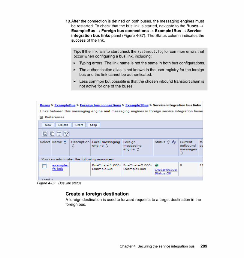
10.After the connection is defined on both buses, the messaging engines must be restarted. To check that the bus link is started, navigate to the Buses → ExampleBus → Foreign bus connections → Example1Bus → Service integration bus links panel (Figure 4-87). The Status column indicates the success of the link.
Figure 4-87 Bus link status
Create a foreign destination A foreign destination is used to forward requests to a target destination in the foreign bus.
Tip: If the link fails to start check the SystemOut.log for common errors that occur when configuring a bus link, including:
� Typing errors. The link name is not the same in both bus configurations.
� The authentication alias is not known in the user registry for the foreign bus and the link cannot be authenticated.
� Less common but possible is that the chosen inbound transport chain is not active for one of the buses.
Chapter 4. Securing the service integration bus 289

Note: Foreign destinations versus direct connections: A foreign destination is not always needed. Connections can be made directly to the target destination from the foreign bus. If considering a direct connection from the local bus to the target destination on the foreign bus be aware that the following conditions can occur and cause the link to block.
� If a user or group is added to the foreign bus sender role and the name of the foreign destination either does not exist or access is not permitted, or no access permissions have been granted to the exception destination on the foreign bus.
� If the exception destination is full.
� If the target destination does not exist and the user does not have access to an exception destination.
Making use of a destination on a foreign bus without using a foreign destination relies on the client being given the foreign bus sender role. While making the configuration simpler, it increases the risk of a misconfigured or malicious client causing problems for the smooth running of the bus. Also, V6.x messaging engines do not expose messages on links between buses, making debugging of problems much harder.
290 WebSphere Application Server V7 Messaging Administration Guide

In this example, a foreign destination is added to Example1Bus to forward requests to a queue (ExampleBusQ1) in ExampleBus. Figure 4-88 shows these components and their relationship.
Figure 4-88 Foreign bus connection components
On the system that hosts Example1Bus, do the following:
1. Navigate to Buses → Example1Bus → Destinations and click New to start the destination wizard.
2. Select Foreign as the destination type and click Next.
3. Enter the target bus and destination name.
Bus Member Bus Member
MessageEngine
QueueDestination
MDB
ActivationSpecification
QueueConnection
FactoryQueue
example-fb-link
ForeignBus
Connection
ForeignDestination
MessageEngine
example-fb-link
Foreign Bus
Connection
BusCluster2.000-Example1Bus
ExampleBusQ1 ExampleBusQ1 BusCluster1.000-ExampleBus
ExampleBusExample1Bus
Chapter 4. Securing the service integration bus 291

The identifier entered must be the same as the destination name on the target bus (Figure 4-89).
Figure 4-89 Foreign destination attributes
Click Next.
4. Click Finish on the summary panel.
292 WebSphere Application Server V7 Messaging Administration Guide
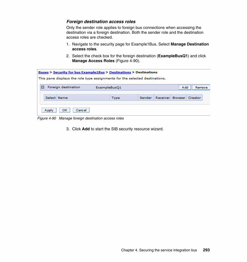
Foreign destination access rolesOnly the sender role applies to foreign bus connections when accessing the destination via a foreign destination. Both the sender role and the destination access roles are checked.
1. Navigate to the security page for Example1Bus. Select Manage Destination access roles.
2. Select the check box for the foreign destination (ExampleBusQ1) and click Manage Access Roles (Figure 4-90).
Figure 4-90 Manage foreign destination access roles
3. Click Add to start the SIB security resource wizard.
Chapter 4. Securing the service integration bus 293

4. Select the search parameters (Figure 4-91).
Figure 4-91 Search for Users or Groups
Click Next.
294 WebSphere Application Server V7 Messaging Administration Guide

5. Select the group (Figure 4-92).
Figure 4-92 Select Users or Groups
Click Next
Chapter 4. Securing the service integration bus 295

6. Select the sender role for the selected groups (Figure 4-93).
Figure 4-93 Select Role Types
Click Next.
7. Click Finish on the summary panel.
8. Save the configuration.
9. View the access role for the foreign destination (Figure 4-94).
Figure 4-94 Access roles for foreign destinations
When using a foreign destination, keep the following in mind:
� The local JMS queue should identify the foreign bus name and the foreign destination name to make this work.
� The target destination will apply its local access control policy in addition to the one being performed by the local bus. This means that the access roles
296 WebSphere Application Server V7 Messaging Administration Guide

granted to users and groups for the foreign destination must also be set on the target destination.
Cross-cell considerations for foreign bus securityIf connecting to a foreign bus in another cell, there are additional considerations to keep in mind. These considerations include:
� When connecting servers within a common node group the host, port, and transport chains are automatically determined. When connecting message engines across cells the boostrap ports for configuration must manually be configured. The bootstrap integration endpoints must be configured in the bus link or can be configured in the JMS connection factories if direct connections are used. Figure 4-95 illustrates the manually configured endpoints.
Figure 4-95 Configure endpoint addresses
Cell
Nodesys6.itso.ral.ibm.com
Node
DeploymentManager
Application Server
Node Agent
Bus
Nodesys2.itso.ral.ibm.com
Node
DeploymentManager
Application Server
Node Agent
Bus
MEME
Bus Link
Cluster.000-AppBus
BusCluster1.000-Example1Bus
sys6.itso.ral.ibm.com:7287:InboundSecureMessaging
sys2.itso.ral.ibm.com:7287:InboundSecureMessaging
Chapter 4. Securing the service integration bus 297

For more information see:
http://publib.boulder.ibm.com/infocenter/wasinfo/v7r0/topic/com.ibm.websphere.pmc.nd.multiplatform.doc/tasks/tjn0033_.html
� If connecting using secure transport chains, SSL between the cells must be configured.
� The cells may use very different security domains. In this case, additional work is necessary to reconcile users to groups so that access is granted. This includes decisions such as whether to use inbound user IDs (Figure 4-85 on page 285).
4.10.2 Configuring using wsadmin
The following examples show the commands that could be executed to configure the foreign bus, foreign destination, and destination access roles. These commands use the jython scripting language and were executed using wsadmin in an interactive mode.
1. Create the foreign bus and foreign bus link on the Example1Bus (Example 4-16).
Example 4-16 Create foreign bus and bus connection on Example1Bus
AdminTask.createSIBForeignBus('[-bus Example1Bus -name ExampleBus -routingType Direct -type SIBus -inboundUserid ]')
AdminTask.createSIBLink('[-bus Example1Bus -preferLocal true -messagingEngine BusCluster2.000-Example1Bus -name example-bus-link -foreignBusName ExampleBus -remoteMessagingEngineName BusCluster1.000-ExampleBus -bootstrapEndpoints -protocolName InboundSecureMessaging -authAlias sys2CellManager01/bus-link-alias]')
2. Create a foreign destination (Example 4-17).
Example 4-17 Create foreign destination
AdminTask.createSIBDestination('[-name ExampleBusQ1 -foreignBus ExampleBus -type FOREIGN -reliability ASSURED_PERSISTENT -maxReliability ASSURED_PERSISTENT -overrideOfQOSByProducerAllowed true -sendAllowed true -description -bus Example1Bus ]')
298 WebSphere Application Server V7 Messaging Administration Guide

3. Manage access roles on a foreign destination (Example 4-18).
Example 4-18 Manage access roles
AdminTask.addGroupToDestinationRole('[-group cn=group13,ou=unit1,o=ibm,c=us -uniqueName cn=group13,ou=unit1,o=ibm,c=us -type ForeignDestination -bus Example1Bus -destination ExampleBusQ1 -foreignBus ExampleBus -role Sender]')
4.11 Other considerations
There remain several items that must be considered when securing a service integration bus:
� The system-defined exception queue is used, by default, by all bus destinations unless a different exception queue is defined. It is important that the appropriate authorization mappings are made for the exception destinations. Messages should be protected even if in error.
� Distribution and Consistency Services (DCS) is used to share the location and availability of messaging resources. Consequently, an attack on this protocol could insert or divert messages. By default, DCS is secured using the server LTPA token, but does not use SSL.
The DCS-Secure transport chain can be selected for the core group if SSL is required. This is not only a bus concern. The DCS is used for many functions. Using secure transport for DCS is a general security-hardening consideration.
Note: If a user or group has the sender role for a destination, that user or group should also be granted the sender role for the associated exception destination.
Chapter 4. Securing the service integration bus 299

Figure 4-96 shows how to modify the default core group to use the DCS_Secure transport chain.
Figure 4-96 Modified DCS
� By default, alias destinations delegate authorization checking to their destination, but authorizations can be asserted by the alias destination.
� The focus of this chapter has been the integration of JMS and messaging clients running on WebSphere application server. The service integration Bus also supports connections for Web services, Java clients, and adapter connectivity for non WebSphere application servers.
300 WebSphere Application Server V7 Messaging Administration Guide

See the information center for more information about these topics and securing the these connection types:
– http://publib.boulder.ibm.com/infocenter/wasinfo/v7r0/topic/com.ibm.websphere.pmc.nd.multiplatform.doc/tasks/tjw_security.html
– http://publib.boulder.ibm.com/infocenter/wasinfo/v7r0/topic/com.ibm.websphere.pmc.nd.multiplatform.doc/concepts/cjr0480_.htmll
– http://publib.boulder.ibm.com/infocenter/wasinfo/v7r0/topic/com.ibm.websphere.pmc.nd.multiplatform.doc/tasks/tjj_thirdparty_ssl.html
4.12 AdminTask wsadmin commands for security
When configuring the bus security throughout this chapter, examples showing the wsadmin equivalents were also provided. However, there are also many commands that were not shown. This section is a small reminder of this and a short guide for how to use wsadmin to get more help should scripting advice be needed.
To acquire assistance and the parameters of the commands use the wsadmin help functions, as shown in Example 4-19.
Example 4-19 Example help
wsadmin>print AdminTask.help('addGroupToTopicSpaceRootRole')WASX8006I: Detailed help for command: addGroupToTopicSpaceRootRole
Description: Gives a group permission to access the topic space for the specified role.
Target object: None
Arguments: *bus - Bus name *topicSpace - Topicspace name *role - The role name. Allowable values are ( Sender | Receiver | IdentityAdopter ) *group - Group name uniqueName - The name that uniquely defines the user or group in the registry
Chapter 4. Securing the service integration bus 301

Steps: None
wsadmin>
In the AdminTask group there are four command groups dedicated to the bus as shown in the Example 4-20. The groups can be listed by executing the command:
wsadmin>print AdminTask.help(“-commandGroups”)
Example 4-20 Bus command groups
SIBAdminBusSecurityCommands - A group of commands that help configure SIB security.SIBAdminCommands - A group of commands that help configure SIB queues and messaging engines.SIBJMSAdminCommands - A group of commands that help configure SIB JMS connection factories, queues and topics.SIBWebServices - A group of commands to configure service integration bus Web services.
The bus security related commands are listed in Example 4-21.
Example 4-21 Bus security commands
wsadmin>print AdminTask.help("SIBAdminBusSecurityCommands")WASX8007I: Detailed help for command group: SIBAdminBusSecurityCommands
Description: A group of commands that help configure SIB security.
Commands:addGroupToBusConnectorRole - Give a group permission to connect to the bus specified.addGroupToDefaultRole - Grants a group default access to all local destinations on the bus for the specified role.addGroupToDestinationRole - Grants a group access to a destination for the specified destination role.addGroupToForeignBusRole - Grants a group access to a foreign bus from the local bus specified for the specified destination role.addGroupToTopicRole - Gives a group permission to access the topic for the specified role.addGroupToTopicSpaceRootRole - Gives a group permission to access the topic space for the specified role.
302 WebSphere Application Server V7 Messaging Administration Guide

addUserToBusConnectorRole - Give a user permission to connect to the bus specified.addUserToDefaultRole - Grants a user default access to all local destinations on the bus for the specified role.addUserToDestinationRole - Grants a user access to a destination for the specified destination role.addUserToForeignBusRole - Grants a user access to a foreign bus from the local bus specified for the specified destination role.addUserToTopicRole - Gives a user permission to access the topic for the specified role.addUserToTopicSpaceRootRole - Gives a user permission to access the topic space for the specified role.isInheritDefaultsForDestination - The command will return "true" if the destination specified inherits the default security permissions.isInheritReceiverForTopic - Shows the inherit receiver defaults for a topic in a given topic space. Returns "true" if the topic inherits from receiver default values.isInheritSenderForTopic - Shows the inherit sender defaults for a topic for a specified topic space. Returns "true" if the topic inherits from sender default values.listAllDestinationsWithRoles - Lists all destinations which have roles defined on them.listAllForeignBusesWithRoles - Lists all foreign buses which have roles defined on them for the specified bus.listAllRolesForGroup - Lists all the roles defined for a specified group.listAllRolesForUser - Lists all the roles defined for a specified user.listAllTopicsWithRoles - Lists all the topics with roles defined for the specified topic space.listGroupsInBusConnectorRole - List the groups in the bus connector rolelistGroupsInDefaultRole - List the groups in the default role.listGroupsInDestinationRole - List the groups in the specified role in the destination security space role for the given destination.listGroupsInForeignBusRole - List the groups in the specified role in the foreign bus security space role for the givenbus.listGroupsInTopicRole - Lists the groups in the specified topic role for the specified topic space.listGroupsInTopicSpaceRootRole - Lists the groups in the specified topic space role for the specified topic space.listInheritDefaultsForDestination - List inherit defaults for destination (deprecated - use isInheritDefaultsForDestinat
Chapter 4. Securing the service integration bus 303

ion instead)listInheritReceiverForTopic - List Inherit Receiver For topic (deprecated - use isInheritReceiverForTopic instead)listInheritSenderForTopic - List Inherit Sender For topic (deprecated - use isInheritSenderForTopic instead)listUsersInBusConnectorRole - List the users in the Bus Connector RolelistUsersInDefaultRole - List the users in a default role.listUsersInDestinationRole - List the users in the specified role in the destination security space role for the given destination.listUsersInForeignBusRole - List the users in the specified role in the foreign bus security space role for the given bus.listUsersInTopicRole - Lists the users in the specified topic role for the specified topic space.listUsersInTopicSpaceRootRole - Lists the users in the specified topic space role for the specified topic space.populateUniqueNames - Attempt to populate any missing unique name entries in the authorization model for the specified bus using its user repository.removeDefaultRoles - Remove all default rolesremoveDestinationRoles - Removes all destination roles defined for the specified destination in the specified bus.removeForeignBusRoles - Remove all foreign bus roles defined for the specified busremoveGroupFromAllRoles - Removes a group from all roles defined.removeGroupFromBusConnectorRole - Remove a group's permission to connect to the specified bus.removeGroupFromDefaultRole - Removes a group from the specified role in the default security space role.removeGroupFromDestinationRole - Removes a group from the specified destination role for the specified destination.removeGroupFromForeignBusRole - Removes a group from the specified foreign bus role for the bus specifiedremoveGroupFromTopicRole - Removes a groups permission to access the topic for the specified role.removeGroupFromTopicSpaceRootRole - Removes a groups permission to access the topic space for the specified role.removeUserFromAllRoles - Removes a user from all roles defined.removeUserFromBusConnectorRole - Remove a user's permission to connect to the specified bus.removeUserFromDefaultRole - Removes a user from the specified role in the default security space role.removeUserFromDestinationRole - Removes a user from the specified destination role for the specified destination.
304 WebSphere Application Server V7 Messaging Administration Guide

removeUserFromForeignBusRole - Removes a user from the specified foreign bus role for the bus specifiedremoveUserFromTopicRole - Removes a users permission to access the topic for the specified role.removeUserFromTopicSpaceRootRole - Removes a users permission to access the topic space for the specified role.setInheritDefaultsForDestination - Allows the override for inheritance for an individual destination. Setting the "inherit" value to true will allow the destination to inherit from the default values.setInheritReceiverForTopic - Allows the override for receiver inheritance for an individual topic on a specified topic space. Setting the "inherit" value to true will allow the topic to inherit from the default values.setInheritSenderForTopic - Allows the override for sender inheritance for an individual topic on a specified topic space. Setting the "inherit" value to true will allow the topic to inherit from the default values.
wsadmin>
Chapter 4. Securing the service integration bus 305

306 WebSphere Application Server V7 Messaging Administration Guide

Related publications
The publications listed in this section are considered particularly suitable for a more detailed discussion of the topics covered in this book.
IBM Redbooks publications
For information about ordering these publications, see “How to get Redbooks” on page 308. Note that some of the documents referenced here may be available in softcopy only.
� WebSphere Application Server V7.0: Technical Overview, REDP-4482
� WebSphere Application Server V7: Concepts, Planning and Design, SG24-7708
� WebSphere Application Server V7 Administration and Configuration Guide, SG24-7615
� WebSphere Application Server V7.0 Security Guide, SG24-7660
� WebSphere Application Server V7.0 Web Services Guide, SG24-7758
� WebSphere Application Server V6.1: JMS Problem Determination, REDP-4330
� WebSphere Application Server V6.1: System Management and Configuration, SG24-7304
Other publications
These publications are also relevant as further information sources:
� Yusuf, Enterprise Messaging Using JMS and WebSphere, Pearson Education, 2004, ISBN 0131468634
� Monson-Haefel, et al, Java Message Service, O’Reilly Media, Incorporated, 2000, ISBN 0596000685
� Giotta, et al, Professional JMS, Wrox Press Inc., 2001, ISBN 1861004931
© Copyright IBM Corp. 2009. All rights reserved. 307
Online resources
These Web sites are also relevant as further information sources:
� WebSphere Application Server V7 Information Center
http://publib.boulder.ibm.com/infocenter/wasinfo/v7r0/index.jsp
� WebSphere Application Server V6.1 Information Center
http://publib.boulder.ibm.com/infocenter/wasinfo/v6r1/index.jsp
� JEE5 Specification
http://jcp.org/en/jsr/detail?id=244
� J2EE Connector Architecture
http://java.sun.com/j2ee/connector/
� Java Message Service (JMS)
http://java.sun.com/products/jms
� WebSphere Application Server performance information
http://www-01.ibm.com/software/webservers/appserv/was/performance.html
How to get Redbooks
You can search for, view, or download Redbooks, Redpapers, Technotes, draft publications and Additional materials, as well as order hardcopy Redbooks publications, at this Web site:
ibm.com/redbooks
Help from IBM
IBM Support and downloads
ibm.com/support
IBM Global Services
ibm.com/services
308 WebSphere Application Server V7 Messaging Administration Guide

WebSphere Application Server V7 M
essaging Administration Guide
WebSphere Application Server
V7 Messaging Adm
inistration
WebSphere Application
Server V7 Messaging
Administration Guide
WebSphere Application Server V7 M
essaging Administration Guide

WebSphere Application
Server V7 Messaging
Administration Guide
WebSphere Application
Server V7 Messaging
Administration Guide


®
SG24-7770-00 ISBN 0738433055
INTERNATIONAL TECHNICALSUPPORTORGANIZATION
BUILDING TECHNICALINFORMATION BASED ONPRACTICAL EXPERIENCE
IBM Redbooks are developed by the IBM International Technical Support Organization. Experts from IBM, Customers and Partners from around the world create timely technical information based on realistic scenarios. Specific recommendations are provided to help you implement IT solutions more effectively in your environment.
For more information:ibm.com/redbooks
®
WebSphere Application Server V7 Messaging Administration Guide
Messaging with the default messaging provider
Configuration and management
Securing the default messaging provider
WebSphere Application Server V7 supports asynchronous messaging based on the Java Message Service (JMS) and the Java EE Connector Architecture (JCA) specifications. Asynchronous messaging support provides applications with the ability to create, send, receive, and read asynchronous requests as messages. WebSphere Application Server provides a default messaging provider, as well as support for WebSphere MQ and generic messaging providers.
This IBM® Redbooks® publication provides information about the messaging features of WebSphere Application Server V7. It contains information about configuring, securing, and managing messaging resources, with a focus on the WebSphere default messaging provider.
Back cover
Top Related