


Languages
Pages
Legal

7361724 (Rev. D 3/8/19)
Installatio
n and Operatio
n Manual
If you have any questions or concerns wheninstalling, operating or maintaining yourwater softener, call our toll free number:
1-888-64 WATER(1-888-649-2837)
or visit www.mortonwatersofteners.comWhen you call, please be prepared to providethe model and serial number of your product,found on the rating decal, located on the rim
below the salt lid hinges.
Do not return water softener to store
For best results use Morton® Clean and Protect® or Morton®
Clean and Protect® Plus Rust Defense® Pellets in your water softener.
Systems tested and certified by NSF Internationalagainst NSF/ANSI Standard 44
for hardness reduction and efficiency, and certified to NSF/ANSI Standard 372.
How to install, operateand maintain your DemandControlled Water Softener
ModelsM20, M27, M30, M34
& MC30
Water Softener

2 Morton® Water Softener Installation & Operation Manual
Protect your new water softener with Morton® Clean and Protect® or Morton®
Clean and Protect® Plus Rust Defense® Pellets
Morton® Water Softener Salt Pellets are made with a time-release formula that works with your softener to help prevent mineral buildupand keep your home’s pipes and appliances working at their best.Whether you’re looking to remove iron and fight buildup, or extend yourwater softener’s life, Morton® has the right salt for you. Use one or bothof our premium formula pellets in any water softener for the best results.
Remember to fill your water softener with Morton®
America’s #1 Brand of Water Softener Salt!

Morton® Water Softener Installation & Operation Manual 3
TABLE OF CONTENTS PageInspect Shipment . . . . . . . . . . . . . . . . . . . . . . . . . . . . . . . . . . . . . . . . . . . . . . . . . . . . . . . . . . . . . . . . . . . . . . . . . . . . 4Dimensions . . . . . . . . . . . . . . . . . . . . . . . . . . . . . . . . . . . . . . . . . . . . . . . . . . . . . . . . . . . . . . . . . . . . . . . . . . . . . . . . 4Specifications & Performance Claims . . . . . . . . . . . . . . . . . . . . . . . . . . . . . . . . . . . . . . . . . . . . . . . . . . . . . . . . . . . . 5Before You Start . . . . . . . . . . . . . . . . . . . . . . . . . . . . . . . . . . . . . . . . . . . . . . . . . . . . . . . . . . . . . . . . . . . . . . . . . . . . 6Water Treatment Information . . . . . . . . . . . . . . . . . . . . . . . . . . . . . . . . . . . . . . . . . . . . . . . . . . . . . . . . . . . . . . . . . . . 6Installation Requirements . . . . . . . . . . . . . . . . . . . . . . . . . . . . . . . . . . . . . . . . . . . . . . . . . . . . . . . . . . . . . . . . . . . . 7-8Installation Instructions . . . . . . . . . . . . . . . . . . . . . . . . . . . . . . . . . . . . . . . . . . . . . . . . . . . . . . . . . . . . . . . . . . . . 9-12Programming the Softener (Models M20, M27, M30 & MC30) § Customizing Features / Options . . . . . . . . 13-15Programming the Softener (Model M34) § Customizing Features / Options . . . . . . . . . . . . . . . . . . . . . . . . . . 16-19Routine Maintenance . . . . . . . . . . . . . . . . . . . . . . . . . . . . . . . . . . . . . . . . . . . . . . . . . . . . . . . . . . . . . . . . . . . . . 20-21Troubleshooting . . . . . . . . . . . . . . . . . . . . . . . . . . . . . . . . . . . . . . . . . . . . . . . . . . . . . . . . . . . . . . . . . . . . . . . . . 22-23Exploded View & Parts List . . . . . . . . . . . . . . . . . . . . . . . . . . . . . . . . . . . . . . . . . . . . . . . . . . . . . . . . . . . . . . . . 24-27Warranty . . . . . . . . . . . . . . . . . . . . . . . . . . . . . . . . . . . . . . . . . . . . . . . . . . . . . . . . . . . . . . . . . . . . . . . . . . . . . . . . . 28
4 Morton® Water Softener Installation & Operation Manual
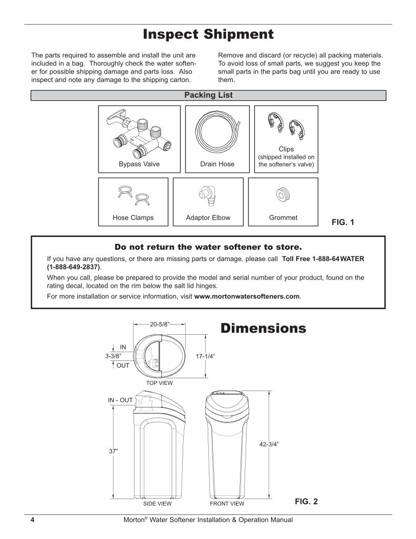
Packing List
Inspect Shipment
Adaptor Elbow
The parts required to assemble and install the unit areincluded in a bag. Thoroughly check the water soften-er for possible shipping damage and parts loss. Alsoinspect and note any damage to the shipping carton.
FIG. 1Hose Clamps
Remove and discard (or recycle) all packing materials.To avoid loss of small parts, we suggest you keep thesmall parts in the parts bag until you are ready to usethem.
Grommet
Dimensions20-5/8”
3-3/8”OUT
IN17-1/4”
TOP VIEW
SIDE VIEW FRONT VIEW
42-3/4”37”
IN - OUT
FIG. 2
Do not return the water softener to store.If you have any questions, or there are missing parts or damage, please call Toll Free 1-888-64WATER(1-888-649-2837).When you call, please be prepared to provide the model and serial number of your product, found on therating decal, located on the rim below the salt lid hinges.For more installation or service information, visit www.mortonwatersofteners.com.
Drain HoseBypass Valve
Clips(shipped installed onthe softener’s valve)

Morton® Water Softener Installation & Operation Manual 5
Specifications & Performance ClaimsModel M20 Model M27 Models
M30 & MC30 Model M34
Model Code o20 o27 o30 o34Regeneration Control Demand Demand Demand Demand
Rated Softening Capacity(Grains @ Salt Dose)
9,310 @ 1.8 lbs.18,000 @ 5.8 lbs.21,500 @ 9.7 lbs.
11,100 @ 2.2 lbs.23,700 @ 7.0 lbs.28,100 @ 11.2 lbs.
13,200 @ 2.9 lbs.25,500 @ 8.0 lbs.30,000 @ 13.1 lbs.
13,700 @ 2.7 lbs.29,200 @ 8.6 lbs.34,900 @ 14.5 lbs.
Rated Efficiency (Grains/Pound of Salt@ Minimum Salt Dose) 5,000 @ 1.8 lbs. 5,040 @ 2.2 lbs. 4,567 @ 2.9 lbs. 5,060 @ 2.7 lbs.
Water Used During Regeneration@ Minimum Salt Dose
2.9 gallons /1,000 grains
2.5 gallons /1,000 grains
2.8 gallons /1,000 grains
2.3 gallons /1,000 grains
Total Water Used Per Regeneration@ Maximum Salt Dose 26.2 gallons 26.7 gallons 33.6 gallons 31.6 gallons
Rated Service Flow Rate 6.5 gpm 6.5 gpm 7.0 gpm 7.8 gpmAmount of High Capacity Ion ExchangeResin .61 cu. ft. .73 cu. ft. .82 cu. ft. .91 cu. ft.
Pressure Drop at Rated Service Flow 11.3 psig 12.1 psig 11.9 psig 14.7 psigWater Supply Max. Hardness 95 gpg 95 gpg 95 gpg 110 gpgWater Supply Max. Clear Water Iron 6 ppm* 7 ppm* 7 ppm* 9 ppm*Water Pressure Limits (min. / max.) 20 - 125 psi**Water Temperature Limits (min. / max.) 40 - 120 °FMinimum Water Supply Flow Rate 3 gpmMaximum Drain Flow Rate 2.2 gpm
*Capacity to reduce clear water iron is substantiated by laboratory test data. State of Wisconsin requires additionaltreatment if water supply contains clear water iron exceeding 5 ppm.
These systems conform to NSF/ANSI 44 for the specific performance claims as verified and substantiated by test data. The efficiency rating is only valid at the stated salt dose. These softeners were efficiency rated according to NSF/ANSIStandard 44. Variable Salt Dose: The salt dose is selected by the electronic controls at regeneration time based on the amount needed.
These softeners conform to NSF/ANSI 44 for the specific performance claims as verified and substantiated by testdata. These models are efficiency rated. The efficiency rating is valid only at the stated salt dose. They have ademand initiated regeneration (D.I.R.) feature that complies with specific performance specifications intended to min-imize the amount of regenerant brine and water used in their operation. Efficiency rated softeners have a rated saltefficiency of not less than 3,350 grains of total hardness exchange per pound of salt (based on sodium chloride) andshall not deliver more salt or be operated at a sustained maximum service flow rate greater than its listed rating.The rated salt efficiency is measured by laboratory tests described in NSF/ANSI Standard 44. These tests representthe maximum possible efficiency that the system can achieve. Operational efficiency is the actual efficiency after thesystem has been installed. It is typically less than the efficiency due to individual application factors including waterhardness, water usage, and other contaminants that reduce the softener’s capacity. These systems are not intend-ed for treating water that is microbiologically unsafe or of unknown quality without adequate disinfection before orafter the systems. For best results use clean grades of water softener salt. Refer to warranty and elsewhere in thismanual for further details on installation and maintenance, parts and service, user responsibility, and further restric-tions, or limitations to the use of the product.
In the state of California: You must turn the Salt Efficiency Feature setting to ON. This may initiatemore frequent recharges. However, it will operate at 4,000 grains per pound of salt or higher. To turnon the Salt Efficiency Feature, follow the instructions in the “Salt Efficiency” section of this manual.

6 Morton® Water Softener Installation & Operation Manual
= The water softener requires a minimum water flow of 3 gallons per minute at the inlet. Maximum allowable inletwater pressure is 125 psi. If daytime pressure is over 80 psi, nighttime pressure may exceed the maximum. Usea pressure reducing valve if necessary (Adding a pressure reducing valve may reduce the flow). If your home isequipped with a back flow preventer, an expansion tank must be installed in accordance with local codes andlaws.
= The water softener works on 24V DC electrical power, supplied by a direct plug-in power supply (included). Besure to use the included power supply and plug it into a nominal 120V, 60 Hz household outlet that is in a drylocation only, grounded and properly protected by an overcurrent device such as a circuit breaker or fuse.
= Do not use this system to treat water that is microbiologically unsafe or of unknown quality without adequate dis-infection upstream or downstream of the system.
European Directive 2002/96/EC requires all electrical and electronic equipment to be disposed of accord-ing to Waste Electrical and Electronic Equipment (WEEE) requirements. This directive or similar laws arein place nationally and can vary from region to region. Please refer to your state and local laws for prop-er disposal of this equipment.
Before You Start
Water Treatment InformationIronIron in water can cause stains on clothing and plumb-ing fixtures. It can negatively affect the taste of food,drinking water, and other beverages. Iron in water ismeasured in parts per million (ppm). The total* ppm ofiron, and type or types*, is determined by chemicalanalysis. Four different types of iron in water are:= Ferrous (clear water) iron= Ferric (red water) iron= Bacterial and organically bound iron= Colloidal and inorganically bound iron (ferrous or
ferric)Ferrous (clear water) iron is soluble and dissolves inwater. This water softener will reduce moderateamounts of this type of iron (see specifications).**Ferrous (clear water) iron is usually detected by takinga sample of water in a clear bottle or glass.Immediately after taking, the sample is clear. As thewater sample stands, it gradually clouds and turnsslightly yellow or brown as air oxidizes the iron. Thisusually occurs in 15 to 30 minutes.When using the softener to reduce Ferrous (clearwater) iron, add 5 grains to the hardness setting forevery 1 ppm of Ferrous (clear water) iron. See "SetWater Hardness Number" section.Ferric (red water), and bacterial and organically boundirons are insoluble. This water softener will notremove ferric or bacterial iron. This iron is visible
immediately when drawn from a faucet because it hasoxidized before reaching the home. It appears assmall cloudy yellow, orange, or reddish suspendedparticles. After the water stands for a period of time,the particles settle to the bottom of the container.Generally these irons are removed from water by filtra-tion. Chlorination is also recommended for bacterialiron.Colloidal and inorganically bound iron is of ferric or fer-rous form that will not filter or exchange out of water.This water softener will not remove colloidal iron. Insome instances, treatment may improve colloidal ironwater. Colloidal iron water usually has a yellowappearance when drawn. After standing for severalhours, the color persists and the iron does not settle,but remains suspended in the water.
SedimentSediment is fine, foreign material particles suspendedin water. This material is most often clay or silt.Extreme amounts of sediment may give the water acloudy appearance, and may require a sediment filterbe installed upstream of the water softener.
* Water may contain one or more of the four types ofiron and any combination of these. Total iron is thesum of the contents.
** Capacity to reduce clear water iron is substantiatedby laboratory test data.
Morton® Water Softener Installation & Operation Manual 7
Installation RequirementsPlumbing CodesAll plumbing must be completed in accordance withnational, state and local plumbing codes.
Laundry TubStandpipe
1-1/2”air gap
Floor Drain
In the state of Massachusetts: The Commonwealthof Massachusetts plumbing code 248-CMR shallbe adhered to. A licensed plumber shall be usedfor this installation.
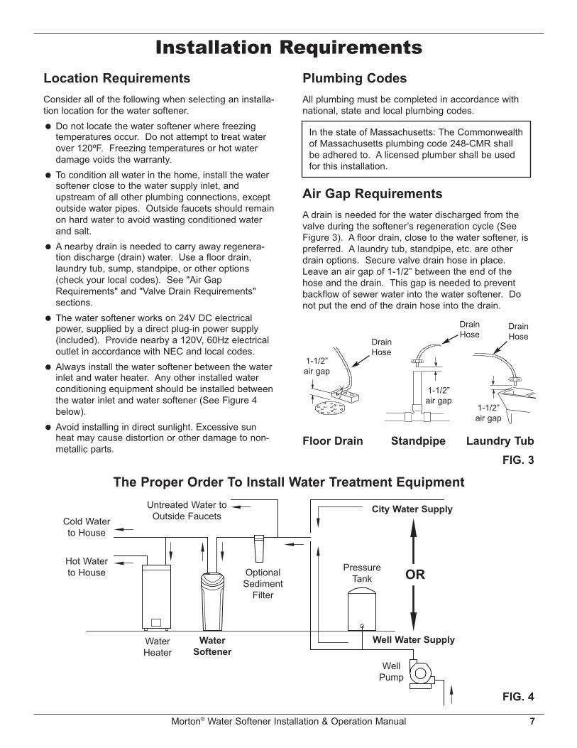
Air Gap RequirementsA drain is needed for the water discharged from thevalve during the softener’s regeneration cycle (SeeFigure 3). A floor drain, close to the water softener, ispreferred. A laundry tub, standpipe, etc. are otherdrain options. Secure valve drain hose in place.Leave an air gap of 1-1/2” between the end of thehose and the drain. This gap is needed to preventbackflow of sewer water into the water softener. Donot put the end of the drain hose into the drain.
FIG. 3
1-1/2”air gap
DrainHose
DrainHose
1-1/2”air gap
Location RequirementsConsider all of the following when selecting an installa-tion location for the water softener.= Do not locate the water softener where freezing
temperatures occur. Do not attempt to treat waterover 120ºF. Freezing temperatures or hot waterdamage voids the warranty.
= To condition all water in the home, install the watersoftener close to the water supply inlet, andupstream of all other plumbing connections, exceptoutside water pipes. Outside faucets should remainon hard water to avoid wasting conditioned waterand salt.
= A nearby drain is needed to carry away regenera-tion discharge (drain) water. Use a floor drain,laundry tub, sump, standpipe, or other options(check your local codes). See "Air GapRequirements" and "Valve Drain Requirements"sections.
= The water softener works on 24V DC electricalpower, supplied by a direct plug-in power supply(included). Provide nearby a 120V, 60Hz electricaloutlet in accordance with NEC and local codes.
= Always install the water softener between the waterinlet and water heater. Any other installed waterconditioning equipment should be installed betweenthe water inlet and water softener (See Figure 4below).
= Avoid installing in direct sunlight. Excessive sunheat may cause distortion or other damage to non-metallic parts.
The Proper Order To Install Water Treatment Equipment
FIG. 4
PressureTank
City Water Supply
Well Water Supply
WellPump
OROptionalSediment
Filter
WaterHeater
WaterSoftener
Untreated Water toOutside Faucets
Hot Waterto House
Cold Waterto House
DrainHose

8 Morton® Water Softener Installation & Operation Manual
Installation Requirements
FIG. 6
Clip
Barbs
1/4 NPTThreads
1/2” Outside Dia.Copper Tube(not included)
Compression Fitting.1/4 NPT x 1/2” O.D.Tube (not included)
Cut barbs from drain fit-ting (pull clip to remove
fitting from valve)
Valve Drain RequirementsUsing the flexible drain hose (included), measure andcut to the length needed. Flexible drain hose is notallowed in all localities (check your plumbing codes). Iflocal codes do not allow use of a flexible drain hose, arigid valve drain run must be used. Purchase a com-pression fitting (1/4 NPT x 1/2 in. minimum tube) and1/2" tubing from your local hardware store. Plumb arigid drain as needed (See Figure 6).NOTE: Avoid drain hose runs longer than 30 feet.
Avoid elevating the hose more than 8 feetabove the floor. Make the valve drain line asshort and direct as possible.
Inlet / Outlet Plumbing OptionsAlways install either a single bypass valve (provided),as shown in Figure 7, or, if desired, parts for a 3 valvebypass system (not included) can be purchased andassembled, as shown in Figure 8. Bypass valvesallow you to turn off water to the softener for mainte-nance if needed, but still have water in house pipes.Use:= Copper pipe= Threaded pipe= PEX (Crosslinked Polyethylene) pipe= CPVC plastic pipe= Other pipe approved for use with potable water
IMPORTANT: Do not solder with plumbing attached tothe single bypass valve. Soldering heatwill damage the plastic valve.
FIG. 7
FIG. 8
Single Bypass ValvePull out for “Service”(Soft water)
Push in for“Bypass”
3 Valve Bypass
From WaterSoftener
To WaterSoftener
InletValve
OutletValve
BypassValve
FIG. 5
1/4” NPTThread Barbs for 3/8”
I.D. Tubing
Drain Hose
Hose Clamp

Morton® Water Softener Installation & Operation Manual 9
Installation Instructions
FIG. 9
To OutsideFaucets
ConditionedWater
Hard WaterMain Water Pipe
Valve DrainElbow
Valve DrainHose*
*Do not connectthe water softenervalve drain hoseto the salt storagetank overflowhose.
Floor Drain
OverflowDrain Elbow
Salt StorageTank OverflowHose*
Secure Valve Drain Hosein place over Floor Drain
NOTE: See “Air Gap Requirements” section.1-1/2”air gap
Step 1. Turn Off Water Supply1. Close the main water supply valve, located near the
well pump or water meter.2. Shut off the electric or fuel supply to the water
heater.3. Open all faucets to drain all water from house pipes.NOTE: Be sure not to drain water from the water
heater, as damage to the water heater ele-ments could result.
Step 2. Assembly1. Morton® water softener models are factory assem-
bled. During installation, unsnap and remove thetop cover, together with the salt lid, to expose thesoftener valve assembly. Set them aside to preventdamage. Check the brinewell to be sure it issecured and vertical (See Figure 11).
2. Lift the brine valve out of the brinewell. Make surethe float stem is parallel to the stand tube so theseals will seat properly during operation. Place thebrine valve back into the bottom of the brinewell andreinstall the brinewell cover.
3. Install the brine tank overflow grommet and elbowinto the 13/16” diameter hole in the back of the saltstorage tank wall.
Step 3. Move the Unit into Place1. Move the water softener into the desired location.
Set it on a solid, level surface.IMPORTANT: Do not place shims directly under the
salt storage tank to level the softener.The weight of the tank, when full ofwater and salt, may cause the tank tofracture at the shim.
continued on next page
Typical Installation
Plug-inPowerSupply
Water SoftenerValve
ToController
Inlet
Outlet
Clips
Pipes
1” NPT SweatAdaptors (notincluded)
SingleBypass ValveLubricated
O-rings
10 Morton® Water Softener Installation & Operation Manual
Installation Instructionscontinued from previous page
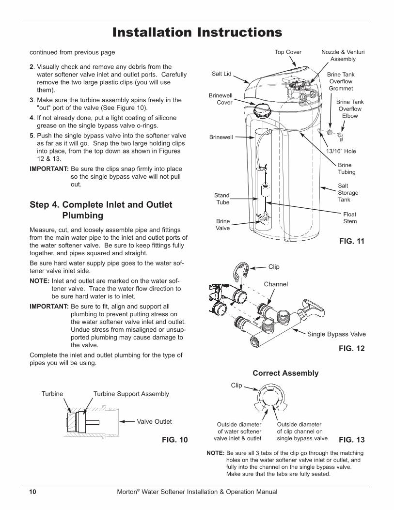
FIG. 12
Clip
Channel
Single Bypass Valve
FIG. 13
Correct AssemblyClip
Outside diameterof clip channel onsingle bypass valve
Outside diameterof water softener
valve inlet & outlet
NOTE: Be sure all 3 tabs of the clip go through the matchingholes on the water softener valve inlet or outlet, andfully into the channel on the single bypass valve.Make sure that the tabs are fully seated.
2. Visually check and remove any debris from thewater softener valve inlet and outlet ports. Carefullyremove the two large plastic clips (you will usethem).
3. Make sure the turbine assembly spins freely in the"out" port of the valve (See Figure 10).
4. If not already done, put a light coating of siliconegrease on the single bypass valve o-rings.
5. Push the single bypass valve into the softener valveas far as it will go. Snap the two large holding clipsinto place, from the top down as shown in Figures12 & 13.
IMPORTANT: Be sure the clips snap firmly into placeso the single bypass valve will not pullout.
Step 4. Complete Inlet and OutletPlumbing
Measure, cut, and loosely assemble pipe and fittingsfrom the main water pipe to the inlet and outlet ports ofthe water softener valve. Be sure to keep fittings fullytogether, and pipes squared and straight.Be sure hard water supply pipe goes to the water sof-tener valve inlet side.NOTE: Inlet and outlet are marked on the water sof-
tener valve. Trace the water flow direction tobe sure hard water is to inlet.
IMPORTANT: Be sure to fit, align and support allplumbing to prevent putting stress onthe water softener valve inlet and outlet.Undue stress from misaligned or unsup-ported plumbing may cause damage tothe valve.
Complete the inlet and outlet plumbing for the type ofpipes you will be using.
FIG. 11
Top Cover
Brine TankOverflow
Elbow
Brine TankOverflowGrommet
13/16” Hole
Salt Lid
SaltStorageTank
FloatStem
BrineTubing
BrinewellCover
StandTube
BrineValve
Brinewell
Nozzle & VenturiAssembly
FIG. 10
Turbine Turbine Support Assembly
Valve Outlet

Morton® Water Softener Installation & Operation Manual 11
Installation InstructionsStep 5. Cold Water Pipe GroundingCAUTION: The house cold water pipe (metal only)
is often used as a ground for the houseelectrical system, The 3-valve bypasstype of installation, shown in Figure 8,will maintain ground continuity. If youuse a plastic bypass valve at the unit,continuity is broken. To restore theground, do the following:
1. Install a #4 copper wire across the removed sectionof main water pipe, securely clamping it at bothends (See Figure 14) - parts not included.
NOTE: Check local plumbing and electrical codesfor proper installation of the ground wire.The installation must conform to them. InMassachusetts, plumbing codes ofMassachusetts shall be conformed to.Consult with your licensed plumber.
FIG. 14
GroundWire
Clamp (2)
Step 7. Install Salt Storage TankOver flow Hose
1. Measure, cut to needed length and connect the 3/8"drain line (provided) to the salt storage tank over-flow elbow and secure in place with a hose clamp.
2 Run the hose to the floor drain, or other suitabledrain point no higher than the drain fitting on the saltstorage tank (This is a gravity drain). If the tankoverfills with water, the excess water flows to thedrain point. Cut the drain line to the desired lengthand route it neatly out of the way.
IMPORTANT: For proper operation of the water soften-er, do not connect the water softenervalve drain hose from Step 6 to the saltstorage tank overflow hose.
Step 8. Pressure Testing for LeaksTo prevent air pressure in the water softener andplumbing system, do the following steps exactly inorder:1. Fully open two or more softened cold water faucets
nearby the water softener, located downstream fromthe water softener.
2. Place the single bypass valve or 3 valve bypass in"bypass" position. See Figures 7 & 8.
3. Fully open the main water supply valve. Run wateruntil there is a steady flow from the opened faucets,with no air bubbles.
4. Place bypass valve(s) in "service" or soft water posi-tion exactly as follows:
= Single bypass valve: Slowly move the valve stemtoward "service," pausing several times to allowthe water softener to fill with water.
= 3 valve bypass: Fully close the bypass valve andopen the outlet valve. Slowly open the inletvalve, pausing several times to allow the watersoftener to fill with water.
5. After about three minutes, open a hot water faucetuntil there is a steady flow and there are no air bub-bles, then close this faucet.
6. Close all cold water faucets and check for leaks atthe plumbing connections that you made.
7. Check for leaks around clips at softener’s inlet andoutlet. If a leak occurs at a clip, depressurize theplumbing (turn off the water supply and openfaucets) before removing clip. When removing clipsat the softener’s inlet or outlet, push the single
Step 6. Install Valve Drain HoseNOTE: See valve drain options on pages 7 & 8.1. Measure, cut to needed length and connect the 3/8"
drain line (provided) to the water softener valvedrain fitting. Use a hose clamp to hold the hose inplace.
IMPORTANT: If codes require a rigid drain line see“Valve Drain requirements" section.
2. Run the drain hose (or a rigid line) to the floor drain.Secure drain hose. This will prevent “whipping'' dur-ing regenerations. Be sure to provide a 1-1/2”minimum air gap to prevent possible sewerwater backup. See “Air Gap Requirements" sec-tion.
NOTE: In addition to a floor drain, you can use a laun-dry tub or standpipe as a good drain point forthis hose.. Avoid long drain hose runs, or ele-vating the hose more than 8’ above the floor. continued on next page

12 Morton® Water Softener Installation & Operation Manual
Installation Instructions
FIG. 15
bypass valve body toward the softener (See Figure15). Improper removal may damage clips. Do notreinstall damaged clips.
continued from previous page
Step 9. Add Water and Salt to theSalt Storage Tank
1. Using a container, add about three gallons of cleanwater into the salt storage tank.
2. Add Morton® System Saver® II Pellets to the storagetank.
NOTE: See Page 20 for additional information onsalt.
Step 10. Plug in the Power SupplyDuring installation, the water softener wiring may bemoved or jostled from place. Check to be sure allleadwire connectors are secure on the back of theelectronic board and be sure all wiring is away fromthe valve gear and motor area, which rotates duringregenerations.1. Plug the water softener’s power supply into an elec-
trical outlet that is not controlled by a switch and isapproved by local codes.
Step 11. Program the Controller1. Install the softener’s top cover and salt lid.
2. Complete the programming steps on: Pages 13 & 14 for Models M20, M27, M30 & MC30
or Pages 16-18 for Model M34.
Step 12. Sanitizing the SoftenerCare is taken at the factory to keep your unit clean andsanitary. Materials used to make the unit will not infector contaminate your water supply, and will not causebacteria to form or grow. However, during shipping,storage, installation and operation, bacteria could getinto the unit. For this reason, sanitizing as follows issuggested* when installing.1. Open salt lid, remove the brinewell cover and pour
about 3 oz. (6 tablespoons) of household bleachinto the softener brinewell. Replace the brinewellcover.
2 Make sure the bypass valve(s) is in the “service”(open) position.
3 Start a recharge: Press the RECHARGE button andhold for 3 seconds, until “RECHARGE NOW” beginsto flash in the display. This recharge draws the sani-tizing bleach into and through the water softener.Any air remaining in the unit is purged to the drain.
4 After the recharge has completed, fully open a coldwater faucet, downstream from the softener, andallow 50 gallons of water to pass through the sys-tem. This should take at least 20 minutes. Closethe faucet.
*Recommended by the Water Quality Association. On somewater supplies, the unit may need periodic disinfecting.
Step 13. Restart the Water HeaterTurn on the electricity or fuel supply to the waterheater and relight the pilot, if applicable.
NOTE: The water heater is filled with hard water and,as hot water is used, it refills with conditionedwater. In a few days, the hot water will be fullyconditioned. To have fully conditioned hotwater immediately, wait until the initial recharge(Step 12) is over. Then, drain the water heater(following instructions for water heater) untilwater runs cold.
...depressurize theplumbing, then pushBypass Valve bodytoward softener
If removingclips...
Questions? Call Toll Free 1-888-64WATER (1-888-649-2837)or visit www.mortonwatersofteners.com
When you call, please be prepared to provide the model and serial number,found on the rating decal, located on the rim below the salt lid hinges.
Morton® Water Softener Installation & Operation Manual 13
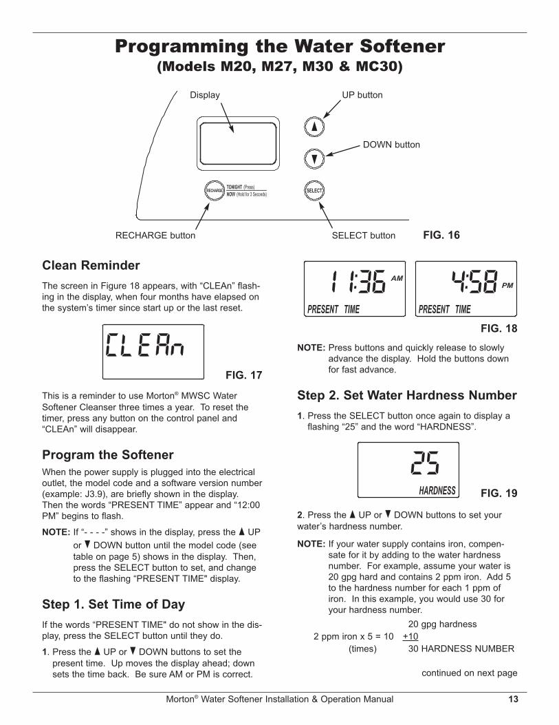
FIG. 16
UP buttonDisplay
RECHARGE button SELECT button
DOWN button
Programming the Water Softener(Models M20, M27, M30 & MC30)
FIG. 17
Clean ReminderThe screen in Figure 18 appears, with “CLEAn” flash-ing in the display, when four months have elapsed onthe system’s timer since start up or the last reset.
This is a reminder to use Morton® MWSC WaterSoftener Cleanser three times a year. To reset thetimer, press any button on the control panel and“CLEAn” will disappear.
Program the SoftenerWhen the power supply is plugged into the electricaloutlet, the model code and a software version number(example: J3.9), are briefly shown in the display.Then the words “PRESENT TIME” appear and “12:00PM” begins to flash.
NOTE: If “- - - -” shows in the display, press the p UPor q DOWN button until the model code (seetable on page 5) shows in the display. Then,press the SELECT button to set, and changeto the flashing “PRESENT TIME" display.
Step 1. Set Time of DayIf the words “PRESENT TIME" do not show in the dis-play, press the SELECT button until they do.
1. Press the p UP or q DOWN buttons to set thepresent time. Up moves the display ahead; downsets the time back. Be sure AM or PM is correct.
FIG. 18NOTE: Press buttons and quickly release to slowly
advance the display. Hold the buttons downfor fast advance.
Step 2. Set Water Hardness Number1. Press the SELECT button once again to display a
flashing “25” and the word “HARDNESS”.
FIG. 19
2. Press the p UP or q DOWN buttons to set yourwater’s hardness number.
NOTE: If your water supply contains iron, compen-sate for it by adding to the water hardnessnumber. For example, assume your water is20 gpg hard and contains 2 ppm iron. Add 5to the hardness number for each 1 ppm ofiron. In this example, you would use 30 foryour hardness number.
20 gpg hardness 2 ppm iron x 5 = 10 +10 (times) 30 HARDNESS NUMBER
continued on next page

14 Morton® Water Softener Installation & Operation Manual
2. If you want to change the recharge start time,press the p UP or q DOWN buttons until thedesired time shows. Be sure AM or PM is correct.
3. Press the SELECT button once more to completethe initial programming. The current time of daywill show in the display.
Step 4. Salt EfficiencyWhen this feature is ON, the water softener will oper-ate at salt efficiencies of 4000 grains of hardness perpound of salt or higher (May recharge more oftenusing smaller salt dosage but more regenerationwater). The softener is shipped with this feature setOFF.
1. Press and hold the SELECT button until one of thescreens in Figure 21 is displayed. Once in this dis-play, press the SELECT button once and one ofthe two displays in Figure 22 is shown.
FIG. 20
Your demand water softener will automatically regen-erate when it needs to, based on water usage. Thetime of day that the automatic recharge cycle beginsmay be changed as follows:
1. Press the SELECT button once again to display aflashing “2:00AM” and the words “RECHARGETIME”. This is a good time for the recharge to startin most households, because water is not in use.
Step 3. Set Recharge (Regeneration)Time
2. Press the p UP or q DOWN buttons to set ON orOFF. When set to ON, the efficiency icon will bedisplayed in the upper right hand corner of the nor-mal run display.
3. Press the SELECT button three times, to return tothe normal run display (See Figure 23).
FIG. 23
FIG. 22Efficiency Icon
Displayed when efficiencyis set to “ON”
California Efficiency Requirement
FIG. 21
Programming the Water Softener(Models M20, M27, M30 & MC30)
Questions? Call Toll Free 1-888-64WATER (1-888-649-2837)or visit www.mortonwatersofteners.com
When you call, please be prepared to provide the model and serial number,found on the rating decal, located on the rim below the salt lid hinges.
Your Morton® Water Softener has a “HighEfficiency” feature with an ON or OFF setting.This softener setting is shipped in the OFF posi-tion, which utilizes the maximum rated capacitywhile most often achieving maximum salt effi-ciencies. When installing this unit in the State ofCalifornia, you MUST turn this setting to the ONposition, which may initiate more frequentrecharges. However it will operate at 4000grains per pound of salt or higher.If you wish to turn the Salt Efficiency feature ON( icon will show in the display), follow theinstructions on this page.

Morton® Water Softener Installation & Operation Manual 15
Adjustable BackwashIf your incoming water supply has higher sedimentsor clear water iron, a longer Backwash and/or FastRinse time may help in keeping the unit cleaner.To change the length of the Backwash:1. Press and hold the SELECT button until the screen
in Figure 26 is displayed.
FIG. 26
2. Press the SELECT button twice, so that “bA TIME”appears in the display (See Figure 27).
FIG. 27
3. Press the p UP or q DOWN buttons to set thelength of Backwash in minutes.
4. When the desired Backwash time appears in thedisplay, press the SELECT button twice to return tothe normal run (time of day) screen.
Adjustable Fast RinseTo change the length of the Fast Rinse:1. Press and hold the SELECT button until the screen
in Figure 26 is displayed.2. Press the SELECT button three times, so that “Fr
TIME” appears in the display (See Figure 28).
FIG. 28
3. Press the p UP or q DOWN buttons to set thelength of Fast Rinse in minutes.
4. When the desired Fast Rinse time appears in thedisplay, press the SELECT button once to return tothe normal run (time of day) screen.
Customizing Features / Options(Models M20, M27, M30 & MC30)
RECHARGE NOW initiated
Recharge NowAt times of greater than normal water use, such aswhen you have guests, you could run out of condi-tioned water before the next scheduled recharge. Ifthis happens, you may want to initiate an immediateregeneration, as follows:
1. Press and hold the RECHARGE button until thewords “RECHARGE NOW" flash in the display.
The softener enters the fill cycle of regeneration rightaway. “RECHARGE NOW” will flash during theregeneration. When completed (in about 2 hours),full water conditioning capacity is restored.NOTE: Avoid using hot water while the softener is
regenerating, because the water heater willrefill with bypass hard water.
Recharge TonightIf you do not want to start an immediate recharge, butwould like an extra recharge at the next presetrecharge time, do the following to schedule arecharge:1. Press and release (do not hold) the RECHARGE
button.
FIG. 24
The words “RECHARGE TONIGHT" flash in the dis-play, and the softener will recharge at the next presetrecharge time (If you decide to cancel the regenera-tion before it begins, press and release theRECHARGE button once more, and “RECHARGETONIGHT” will disappear from the display). Duringregeneration, the word “RECHARGE NOW" will flashin the screen. When completed, full water condition-ing capacity is restored.
RECHARGE TONIGHT initiatedFIG. 25

16 Morton® Water Softener Installation & Operation Manual
Programming the Water Softener (Model M34)
FIG. 29
Low Salt LED IndicatorDisplay
SELECT button DOWN buttonRECHARGE button
UP button
FIG. 30
Program the SoftenerWhen the power supply is plugged into the electricaloutlet, the model code and a software version number(example: J3.9), are briefly shown in the display.Then the words “PRESENT TIME” appear and “12:00PM” begins to flash.
NOTE: If “- - - -” shows in the display, press the p UPor q DOWN button until the model code (seetable on page 5) shows in the display. Then,press the SELECT button to set, and changeto the flashing “SET TIME" display.
Step 1. Set Time of DayIf the words “SET TIME" do not show in the display,press the SELECT button until they do.
1. Press the p UP or q DOWN buttons to set thepresent time. Up moves the display ahead; downsets the time back. Be sure AM or PM is correct.
Low Salt Light / Clean ReminderWhen the water softener is connected to electricalpower, the light on the control panel will operate asfollows:= Light flashing, with the time of day shown inthe display - The salt monitor system indicates alow salt level and needs to be set. See “Set SaltLevel” on Page 17.
= Light flashing, with “CLEAn” flashing in thedisplay (See Fig. 30) - Four months have elapsedon the system’s timer since start up or the lastreset.
This is a reminder to use Morton® MWSC WaterSoftener Cleanser three times a year. To reset thetimer, press any button on the control panel and“CLEAn” will disappear. The light will stop flashing,unless the system is also low on salt (see above).
FIG. 31NOTE: Press buttons and quickly release to slowly
advance the display. Hold the buttons downfor fast advance.
Questions? Call Toll Free 1-888-64WATER (1-888-649-2837)or visit www.mortonwatersofteners.com
When you call, please be prepared to provide the model and serial number,found on the rating decal, located on the rim below the salt lid hinges.

Morton® Water Softener Installation & Operation Manual 17
FIG. 34
LEVELSALT
SaltLevel
Brine-well
Num -bers
Programming the Water Softener (Model M34)
FIG. 32
Step 2. Set Water Hardness Number1. Press the SELECT button once again to display a
flashing “25” and the word “HARDNESS”.
2. Press the p UP or q DOWN buttons to set yourwater’s hardness number.NOTE: If your water supply contains iron, compen-
sate for it by adding to the water hardnessnumber. For example, assume your water is20 gpg hard and contains 2 ppm iron. Add 5to the hardness number for each 1 ppm ofiron. In this example, you would use 30 foryour hardness number.
20 gpg hardness 2 ppm iron x 5 = 10 +10 (times) 30 HARDNESS NUMBER
FIG. 33
Step 4. Set Salt LevelThe water softener has a low salt indicator light toremind you to refill the storage tank with salt.NOTE: You must set salt level each time salt is added
to the water softener.To set this monitor system:1. Lift the salt lid and level the salt in the storage tank.2. The salt level scale, on the brinewell inside the
tank, has numbers from 0 to 8 (See Fig. 34).Observe the highest number the leveled salt is at,or closest to.
3. Press the SELECT button to display the words“SET SALT LEVEL”.
4. Press the p UP or q DOWN buttons until the num-ber on the screen corresponds to the salt level. Atlevel 2 or below, the “Low Salt" indicator light willflash. If you wish to turn this feature off, press theq DOWN button past 0, and the word “OFF” flash-es in the display.
5. Press the SELECT button once more to completethe initial programming. The current time of daywill show in the display.
continued on next page
2. If you want to change the recharge start time,press the p UP or q DOWN buttons until thedesired time shows. Be sure AM or PM is correct.
Your demand water softener will automatically regen-erate when it needs to, based on water usage. Thetime of day that the automatic recharge cycle beginsmay be changed as follows:
1. Press the SELECT button once again to display aflashing “2:00AM” and the words “SET RECHARGETIME”. This is a good time for the recharge to startin most households, because water is not in use.
Step 3. Set Recharge (Regeneration)Time
18 Morton® Water Softener Installation & Operation Manual
Programming the Water Softener (Model M34)
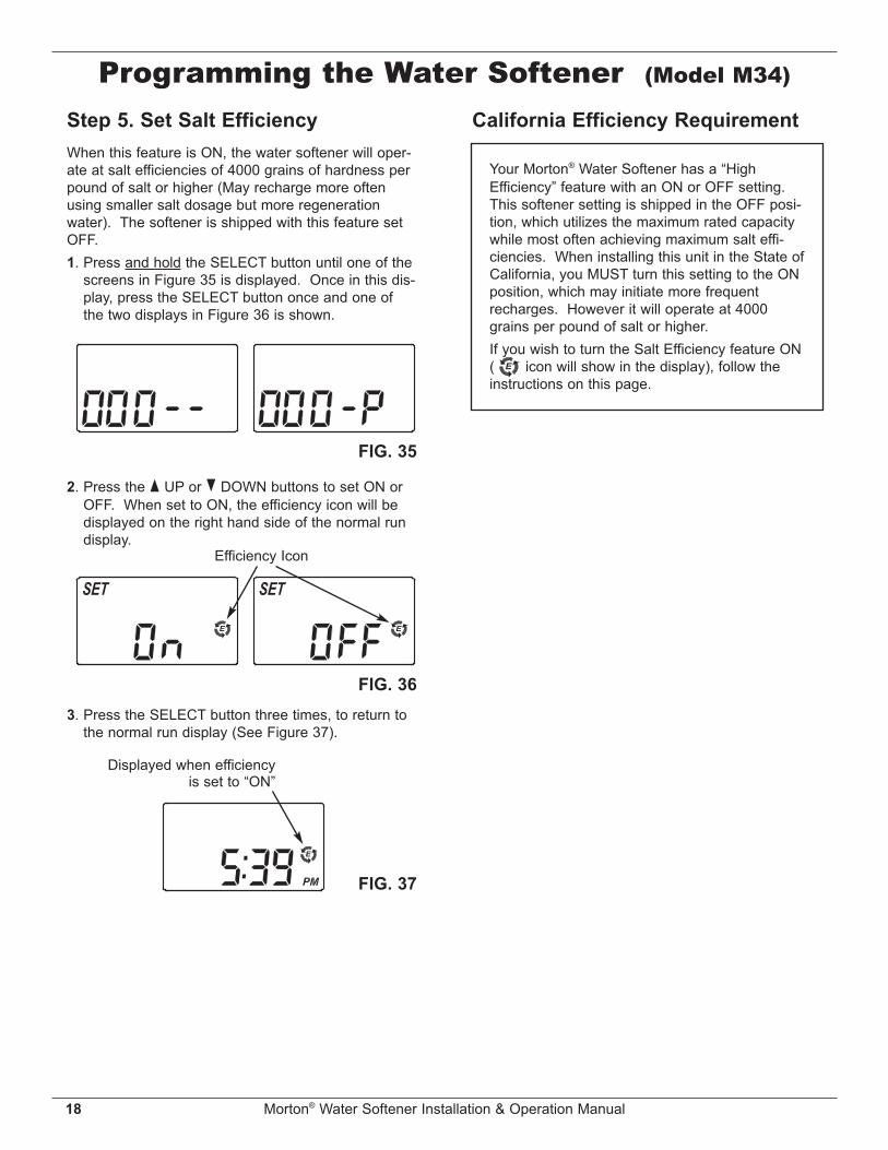
2. Press the p UP or q DOWN buttons to set ON orOFF. When set to ON, the efficiency icon will bedisplayed on the right hand side of the normal rundisplay.
3. Press the SELECT button three times, to return tothe normal run display (See Figure 37).
FIG. 35
FIG. 36
Efficiency Icon
FIG. 37
Displayed when efficiencyis set to “ON”
California Efficiency RequirementStep 5. Set Salt EfficiencyWhen this feature is ON, the water softener will oper-ate at salt efficiencies of 4000 grains of hardness perpound of salt or higher (May recharge more oftenusing smaller salt dosage but more regenerationwater). The softener is shipped with this feature setOFF.1. Press and hold the SELECT button until one of the
screens in Figure 35 is displayed. Once in this dis-play, press the SELECT button once and one ofthe two displays in Figure 36 is shown.
Your Morton® Water Softener has a “HighEfficiency” feature with an ON or OFF setting.This softener setting is shipped in the OFF posi-tion, which utilizes the maximum rated capacitywhile most often achieving maximum salt effi-ciencies. When installing this unit in the State ofCalifornia, you MUST turn this setting to the ONposition, which may initiate more frequentrecharges. However it will operate at 4000grains per pound of salt or higher.If you wish to turn the Salt Efficiency feature ON( icon will show in the display), follow theinstructions on this page.
Morton® Water Softener Installation & Operation Manual 19
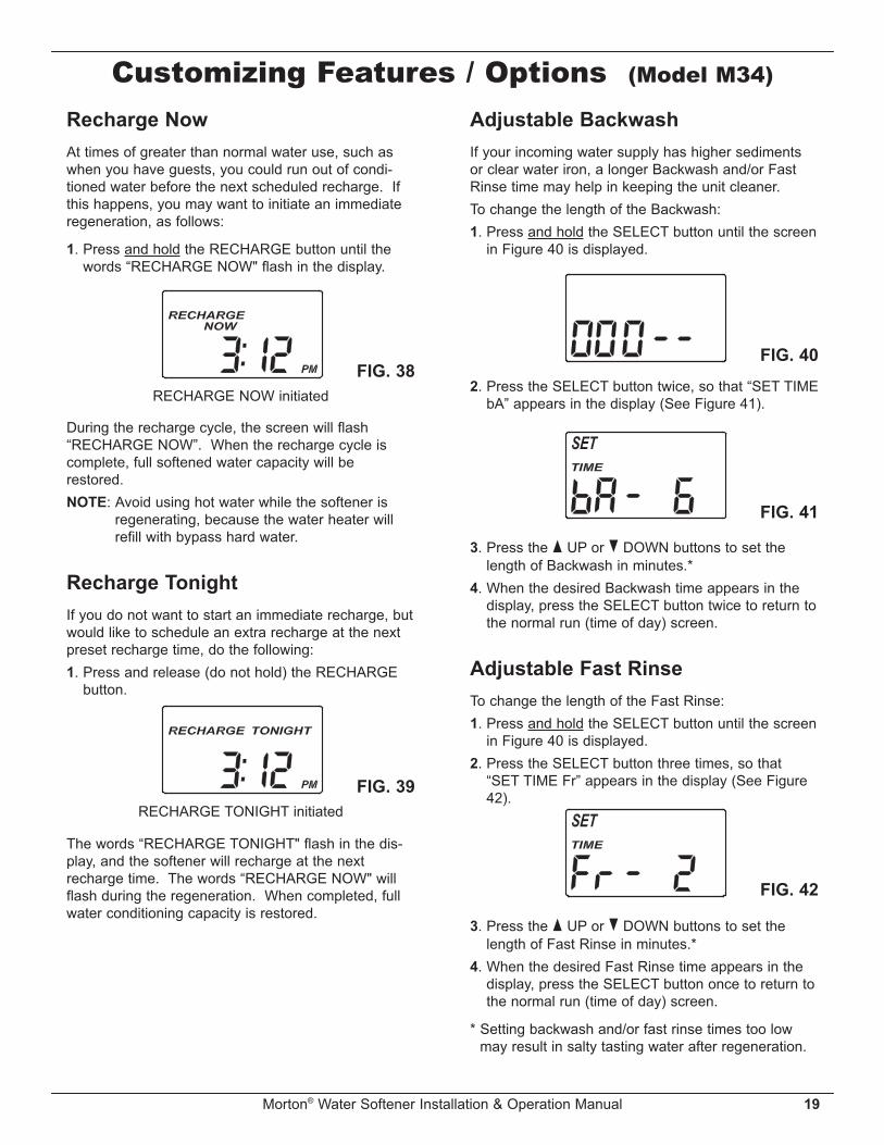
Customizing Features / Options (Model M34)Recharge NowAt times of greater than normal water use, such aswhen you have guests, you could run out of condi-tioned water before the next scheduled recharge. Ifthis happens, you may want to initiate an immediateregeneration, as follows:
1. Press and hold the RECHARGE button until thewords “RECHARGE NOW" flash in the display.
RECHARGE NOW initiatedFIG. 38
During the recharge cycle, the screen will flash“RECHARGE NOW”. When the recharge cycle iscomplete, full softened water capacity will berestored.NOTE: Avoid using hot water while the softener is
regenerating, because the water heater willrefill with bypass hard water.
Recharge TonightIf you do not want to start an immediate recharge, butwould like to schedule an extra recharge at the nextpreset recharge time, do the following:1. Press and release (do not hold) the RECHARGE
button.
RECHARGE TONIGHT initiatedFIG. 39
The words “RECHARGE TONIGHT" flash in the dis-play, and the softener will recharge at the nextrecharge time. The words “RECHARGE NOW" willflash during the regeneration. When completed, fullwater conditioning capacity is restored.
Adjustable BackwashIf your incoming water supply has higher sedimentsor clear water iron, a longer Backwash and/or FastRinse time may help in keeping the unit cleaner.To change the length of the Backwash:1. Press and hold the SELECT button until the screen
in Figure 40 is displayed.
FIG. 40
FIG. 41
FIG. 42
2. Press the SELECT button twice, so that “SET TIMEbA” appears in the display (See Figure 41).
3. Press the p UP or q DOWN buttons to set thelength of Backwash in minutes.*
4. When the desired Backwash time appears in thedisplay, press the SELECT button twice to return tothe normal run (time of day) screen.
Adjustable Fast RinseTo change the length of the Fast Rinse:1. Press and hold the SELECT button until the screen
in Figure 40 is displayed.2. Press the SELECT button three times, so that
“SET TIME Fr” appears in the display (See Figure42).
3. Press the p UP or q DOWN buttons to set thelength of Fast Rinse in minutes.*
4. When the desired Fast Rinse time appears in thedisplay, press the SELECT button once to return tothe normal run (time of day) screen.
* Setting backwash and/or fast rinse times too lowmay result in salty tasting water after regeneration.

20 Morton® Water Softener Installation & Operation Manual
FIG. 43
BroomHandle
PencilMark
1” - 2”
Salt
SaltBridge
WaterLevel
Push Tool intoSalt Bridge to
Break
Routine Maintenance
Power Outage MemoryIf electrical power to the softener is interrupted, thetime display is blank, but the electronic controllerkeeps correct time for several hours. When power isrestored, you must reset the present time only if thedisplay is flashing. All other settings are maintainedand never require resetting unless a change isdesired. If the time is flashing after a long power out-age, the softener continues to work as it should toprovide you with soft water. However, regenerationsmay occur at the wrong time of day until you reset theclock to the correct time of day.
NOTE: If the water softener was regenerating whenpower was lost, it will now finish the cycle.
CustomizingFeatures / Options
(All Models)Refilling with SaltLift the salt lid and check the salt storage level fre-quently. If the water softener uses all the Morton®
Clean and Protect™ or Clean and Protect™ Plus RustDefense™ Pellets before you refill it, you will experi-ence hard water. Until you have established a refillingroutine, check the salt every two or three weeks.Always add if less than 1/4 full. Be sure the brinewellcover is on.
NOTE: In humid areas, it is best to keep the salt stor-age level lower, and to refill more often toavoid salt “bridging”.
Recommended Salt: We recommend using Morton®
Clean and Protect™ or Clean and Protect™ Plus RustDefense™ Pellets in the familiar yellow bag. For softwater, nothing works harder. Guaranteed®.
Salt Not Recommended: Rock salt, high in impuri-ties, block, granulated, table, ice melting, ice creammaking salts, etc., are not recommended.Salt with Iron Removing Additives: Some saltshave an additive to help a water conditioner handleiron in a water supply. For this we recommendMorton® Rust Remover Super Pellets® in the green bag.
Breaking a Salt BridgeSometimes, a hard crust or salt “bridge” forms in thebrine tank. It is usually caused by high humidity or thewrong kind of salt. When the salt “bridges,” an emptyspace forms between the water and the salt. Then,salt will not dissolve in the water to make brine.Without brine, the resin bed is not recharged and hardwater will result.If the storage tank is full of salt, it is difficult to tell ifyou have a salt bridge. A bridge may be underneathloose salt. Take a broom handle, or like tool, and holdit next to the water softener. Measure the distancefrom the floor to the rim of the water softener. Then,carefully push the broom handle straight down into thesalt. If a hard object is felt before the pencil mark iseven with the top, it is most likely a salt bridge.Carefully push into the bridge in several places tobreak it. Do not use any sharp or pointed objects asyou may puncture the brine tank. Do not try to breakthe salt bridge by pounding on the outside of the salttank. You may damage the tank.

Morton® Water Softener Installation & Operation Manual 21
Routine MaintenanceProtect the Water Softener fromFreezingIf the softener is installed where it could freeze (sum-mer cabin, lake home, etc.), you must drain all waterfrom it to stop possible freeze damage. To drain thesoftener:1. Close the shut-off valve on the house main water
pipe, near the water meter or pressure tank.2. Open a faucet in the soft water pipes to vent pres-
sure in the softener.3. Move the stem in the single bypass valve to bypass.
Close the inlet and outlet valve in a 3 valve bypasssystem, and open the bypass valve. If you wantwater in the house pipes again, reopen the shut-offvalve on the main water pipe.
4. Unplug the power supply at the wall outlet. Removethe softener’s top cover, together with the salt lid.Take off both drain hoses if they will interfere withmoving the softener into position over the drain.
5. Push the bypass valve body toward the softener (asshown in Figure 15) and carefully remove the largeholding clips at the softener inlet and outlet.Separate the softener from the plastic installationadaptors, or from the bypass valve.
6. Lay a piece of 2 inch thick board near the floor drain(See Figure 45).
7. Move the softener close to the drain. Slowly andgently, tip it over until the rim rests on the woodblock with the inlet and outlet over the drain. Do notallow the softener’s weight to rest on the inlet andoutlet fittings or they may break.
8. Tip the bottom of the softener up a few inches andhold until all water has drained. Leave the softenerlaying like this until you are ready to use it. Plug theinlet and outlet with clean rags to keep dirt, bugs,etc. out.
Floor Drain FIG. 45Wood Block
FIG. 44
CapO-ring Seal
Screen SupportScreen
Gasket*Flow Plug (HVDC)
Housing
FerruleNut
Cone Screen
*Flow Plug
*Install with letteredside up, concaveside down.
Cleaning the Nozzle & VenturiA clean nozzle & venturi (See Figure 44) is a necessityfor the water softener to work properly. This smallcomponent creates the suction to move brine from thebrine tank, into the resin tank. If it should becomeplugged with sand, silt, dirt, etc., the water softener willnot work, and hard water will result.
Nozzle & Venturi Disc
IMPORTANT: Be sure small hole in the gasket is cen-tered directly over the small hole in the nozzle & ven-turi housing. Be sure the numbers are facing up.
To get access to the nozzle & venturi, remove thewater softener’s top cover. Put the bypass valve(s)into the bypass position. Be sure the water softener isin soft water (service) cycle (no water pressure at noz-zle & venturi). Then, holding the nozzle & venturihousing with one hand, un screw the cap. Do not losethe o-ring seal. Lift out the screen support and screen.Then, remove the nozzle & venturi disc, gasket andflow plug(s). Wash the parts in warm, soapy waterand rinse in fresh water. Be sure to clean both the topand bottom of the nozzle & venturi disc. If needed,use a small brush to remove iron or dirt. Do notscratch, misshape, etc., surfaces of the nozzle & ven-turi.Carefully replace all parts in the correct order.Lubricate the o-ring seal with silicone grease andlocate in place. Install and tighten the cap by hand,while supporting the housing. Overtightening maybreak the cap or housing. Put the bypass valve(s) intoservice (soft water) position.Recharge the softener to reduce water level in thetank. This will also assure that the softener is com-pletely recharged and ready to provide softened wateragain. Check the water level in the tank by lookingdown the brinewell. If the water level does not dropafter a recharge, the problem has not been resolved.Call 1-888-64 WATER or visit www.mortonwatersoften-ers.com.

22 Morton® Water Softener Installation & Operation Manual
While an error code appears in the display, all buttonsare inoperable except the SELECT button. SELECTremains operational so the service person can per-form the Manual Advance Diagnostics, see below, tofurther isolate the problem.Procedure for removing error code from dis-play: 1. Unplug power supply from electrical outlet. 2. Correct problem. 3. Plug power supply back in. 4. Wait 8 minutes. The error code will return if
the problem was not corrected.
Manual Advance DiagnosticsUse the following procedures to advance the watersoftener through the regeneration cycles to checkoperation.Remove the top cover to expose the valve and ob -serve cam and switch operation during valve rotation.1. Press and hold SELECT for 3 seconds until “000”
shows in the display, then release.2. The 3 digits indicate water meter operation as fol-
lows: 000 (steady) = Soft water not in use, and no flow
through the meter. Open a nearby soft water faucet. 000 to 199 (continual) = Repeats for each gallon
of water passing throughthe meter.
3. The letter “P” and a dash (or dashes) indicatePOSITION switch operation (See Figure 47). If the
4. Use the RECHARGE button to manually advancethe valve into each cycle and check correct switchoperation.
NOTE: Be sure water is in contact with the salt, andnot separated by a salt bridge (See "BreakingA Salt Bridge" section).
5. While in this diagnostic screen, the following infor-mation is available and may be beneficial for vari-ous reasons. This information is retained by thecomputer from the first time electrical power isapplied to the electronic controller.
a. Press the p UP button to display the number ofdays this electronic control has had electricalpower applied.
b. Press the q DOWN button to display the numberof regenerations initiated by this electronic con-trol since the code number was entered.
6. Press and hold the SELECT button until the modelcode (see table on page 5) shows in the display.This code identifies the softener model. If an incor-rect model code is displayed, the softener will oper-ate on incorrect configuration data.
7. To change the code number, press the p UP orq DOWN button until the correct code shows.
8. To return to the present time display, press theSELECT button.
WaterMeter
Switch
Automatic Electronic DiagnosticsThis water softener has a self-diagnostic function forthe electrical system (except input power and/or watermeter). The water softener monitors electronic com-ponents and circuits for correct operation. If a mal-function occurs, an error code appears in the display.
FIG. 46
FIG. 47
letter appears, the switch is closed. If the dashshows, the switch is open.
Troubleshooting
FIG. 48
Morton® Water Softener Installation & Operation Manual 23
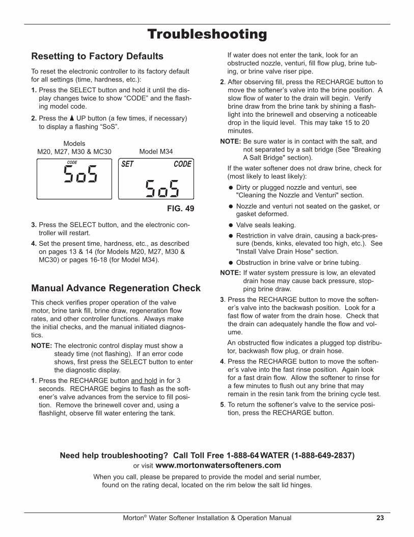
TroubleshootingResetting to Factory DefaultsTo reset the electronic controller to its factory defaultfor all settings (time, hardness, etc.):1. Press the SELECT button and hold it until the dis-
play changes twice to show “CODE” and the flash-ing model code.
2. Press the p UP button (a few times, if necessary)to display a flashing “SoS”.
3. Press the SELECT button, and the electronic con-troller will restart.
4. Set the present time, hardness, etc., as describedon pages 13 & 14 (for Models M20, M27, M30 &MC30) or pages 16-18 (for Model M34).
FIG. 49
Model M34Models
M20, M27, M30 & MC30
This check verifies proper operation of the valvemotor, brine tank fill, brine draw, regeneration flowrates, and other controller functions. Always makethe initial checks, and the manual initiated diagnos-tics.NOTE: The electronic control display must show a
steady time (not flashing). If an error codeshows, first press the SELECT button to enterthe diagnostic display.
1. Press the RECHARGE button and hold in for 3seconds. RECHARGE begins to flash as the soft-ener’s valve advances from the service to fill posi-tion. Remove the brinewell cover and, using aflashlight, observe fill water entering the tank.
Manual Advance Regeneration Check
If water does not enter the tank, look for anobstructed nozzle, venturi, fill flow plug, brine tub-ing, or brine valve riser pipe.
2. After observing fill, press the RECHARGE button tomove the softener’s valve into the brine position. Aslow flow of water to the drain will begin. Verifybrine draw from the brine tank by shining a flash-light into the brinewell and observing a noticeabledrop in the liquid level. This may take 15 to 20minutes.
NOTE: Be sure water is in contact with the salt, andnot separated by a salt bridge (See "BreakingA Salt Bridge" section).
If the water softener does not draw brine, check for(most likely to least likely):
= Dirty or plugged nozzle and venturi, see"Cleaning the Nozzle and Venturi" section.
= Nozzle and venturi not seated on the gasket, orgasket deformed.
= Valve seals leaking. = Restriction in valve drain, causing a back-pres-
sure (bends, kinks, elevated too high, etc.). See"Install Valve Drain Hose" section.
= Obstruction in brine valve or brine tubing.NOTE: If water system pressure is low, an elevated
drain hose may cause back pressure, stop-ping brine draw.
3. Press the RECHARGE button to move the soften-er’s valve into the backwash position. Look for afast flow of water from the drain hose. Check thatthe drain can adequately handle the flow and vol-ume.
An obstructed flow indicates a plugged top distribu-tor, backwash flow plug, or drain hose.
4. Press the RECHARGE button to move the soften-er’s valve into the fast rinse position. Again lookfor a fast drain flow. Allow the softener to rinse fora few minutes to flush out any brine that mayremain in the resin tank from the brining cycle test.
5. To return the softener’s valve to the service posi-tion, press the RECHARGE button.
Need help troubleshooting? Call Toll Free 1-888-64WATER (1-888-649-2837)or visit www.mortonwatersofteners.com
When you call, please be prepared to provide the model and serial number,found on the rating decal, located on the rim below the salt lid hinges.

24 Morton® Water Softener Installation & Operation Manual
8
7
6
5
Softener Exploded View
26
25
27
14
15
1117
18
10
21
22
23
24
7
5
3
8
9
6
Valve AssemblySee Pages 26 & 27
for parts
42
1
20
Softener Exploded View
19
13
12
16
70
71
72

Morton® Water Softener Installation & Operation Manual 25
Softener Parts ListKeyNo. Part No. Description
– 7112963 Distributor O-Ring Kit(includes Key Nos. 1-3)
1 á O-Ring, 2-7/8” x 3-1/4”
2 á O-Ring, 13/16” x 1-1/16”
3 á O-Ring, 2-3/4” x 3”
4 7077870 Top Distributor
5 7105047 Repl. Bottom Distributor
– 7331177 Tank Neck Clamp Kit(includes Key Nos. 6 & 7)
6 á Clamp Section (2 req.)
7 á Retainer Clip (2 req.)
87114787 Repl. Resin Tank, 8” x 35”,
Models M20 & M27
7264922 Repl. Resin Tank, 9” x 35”,Models M30, MC30 & M34
9 0502272 Resin, 1 cu. ft.
10 7331143 Repl. Brine Tank
11 7330977 Rim
12 7330985 Top Cover (order decal below)
137331371 Faceplate Decal,
Models M20, M27, M30 & MC307331630 Faceplate Decal, Model M34
14 7330993 Salt Lid (order decal below)
¢7331339 Instruction Decal,
Models M20, M27, M30 & MC307331614 Instruction Decal, Model M34
KeyNo. Part No. Description
157331818
Repl. Electronic Control Board(PWA), Models M20, M27, M30 &MC30
7331834 Repl. Electronic Control Board(PWA), Model M34
16 7351054 Power Supply, 24V DC
17 7155115 Cover, Brinewell
187109871 Brinewell,
Models M20, M27, M30 & MC30
7214375 Brinewell Assembly (including saltlevel decal), Model M34
– 7332204 Brinewell Mounting Hardware Kit(includes Key Nos. 19-21)
19 á Wing Nut, 1/4-20
20 á Spacer, 3/4” long
21 á Screw, 1/4-20 x 1-1/2”
– 7331258 Overflow Hose Adaptor Kit(includes Key Nos. 22-24)
22 á Adaptor Elbow
23 á Grommet
24 á Hose Clamp
25 7310202 Brine Valve Assembly
26 7327568 Float, Stem & Guide Assembly
27 7139999 Drain Hose
¢ 7361724 Owner’s Manual
¢ Not illustrated.
Questions? Call Toll Free 1-888-64WATER (1-888-649-2837)or visit www.mortonwatersofteners.com
When you call, please be prepared to provide the model and serial number,found on the rating decal, located on the rim below the salt lid hinges.
26 Morton® Water Softener Installation & Operation Manual
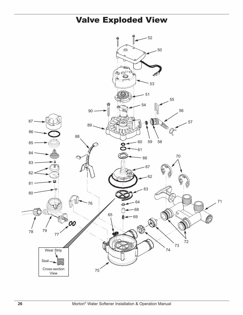
Valve Exploded View
50
52
53
5155
56
59 58
57
60
61
66
67
62
63
64
68
69
70
71
75
65
76
777978
80
81
82
Wear Strip
Seal
Cross-sectionView
83
84
85
86
87
88
89
9054
7273
74

Morton® Water Softener Installation & Operation Manual 27
Valve Parts ListKeyNo. Part No. Description
– 7373810 Motor, Cam & Gear Kit, 3/4”(includes Key Nos. 50-52)
50 á Motor
51 á Cam & Gear
52 7338111 Screw, #6-19 x 1-3/8” (2 req.)
53 7337474 Motor Mount
54 7030713 Switch
– 7331185 Drain Hose Adaptor Kit(includes Key Nos. 55-59)
55 á Clip, Drain
56 á Drain Hose Adaptor
57 á Hose Clamp
58 á O-Ring, 5/8” x 13/16”
59 á Flow Plug, 2.0 gpm
– 7129716 Seal Kit (includes Key Nos. 60-65)
60 á O-Ring, 7/16” x 5/8”
61 á O-Ring, 3/4” x 15/16”
62 á O-Ring, 3-3/8” x 3-5/8”
63 á Rotor Seal
64 á O-Ring, 3/8” x 9/16”
65 á Seal, Nozzle & Venturi
66 7082087 Wave Washer
67 7199232 Rotor & Disc
– 7342665 Drain Plug Kit, 3/4”(includes Key Nos. 64, 68 & 69)
68 á Plug, Drain Seal
69 á Spring
KeyNo. Part No. Description
70 7337563 Clip, 3/4”, pack of 4
71 7370286 Bypass Valve Assembly, 3/4”, in -cluding 2 O-Rings (See Key No. 72)
72 7337571 O-Ring, 15/16” x 1-3/16”, pack of 4
– 7113040Turbine & Support Assembly,including 2 O-Rings (See Key No.72) & 1 ea. of Key Nos. 73 & 74
73 á Turbine Support & Shaft
74 á Turbine
75 7082053 Valve Body
76 7081201 Retainer, Nozzle & Venturi
77 7342649 O-Ring, 1/4” x 3/8”, pack of 2
78 1202600 Nut - Ferrule
– 7238450 Nozzle & Venturi Assembly(includes Key Nos. 76, 77 & 79-87)
79 7081104 Housing, Nozzle & Venturi
80 7095030 Cone Screen
81 1148800 Flow Plug, .3 gpm
827187772 Nozzle & Venturi Gasket Kit
7204362 Gasket Only
83 0521829 Flow Plug, .1 gpm
84 7146043 Screen
85 7167659 Screen Support
86 7170262 O-Ring, 1-1/8” x 1-3/8”
87 7199729 Cap
88 7309803 Wire Harness, Sensor
89 7337466 Valve Cover
90 7342657 Screw, #10-14 x 5 cm, pack of 5
Questions? Call Toll Free 1-888-64WATER (1-888-649-2837)or visit www.mortonwatersofteners.com
When you call, please be prepared to provide the model and serial number,found on the rating decal, located on the rim below the salt lid hinges.

WATER SOFTENER LIMITED WARRANTYSeller warrants,to the original owner, that: ● For a period of ten (10) years from the date of purchase, the salt storage tank and fiberglass mineral tank
will not rust, corrode, leak, burst, or fail to perform to their specifications. ● For a period of one (1) year from the date of purchase, all other parts will be free of defects in material and
workmanship.
If, during such respective period, a part proves to be defective, Seller will ship a replacement part, directly toyour home, without charge. If you have questions regarding a Morton water softener or MWSC, need assistance with installation or trou-bleshooting, wish to order a part or report a warranty issue, we are just a phone call away. Simply dial 1-888-64WATER (1-888-649-2837) for assistance, or visit www.mortonwatersofteners.com.
This water softener is manufactured for Morton Salt, Inc., P.O. Box 25290, Woodbury, MN 55125-0290
General ProvisionsThe warranty does not apply to any defect, malfunction or failure arising from, relating to or caused by: (i)operation at water pressures which exceed 125 psi or at water temperatures which exceed 120°F; (ii) repairsmade by others than, or without the consent of, Seller or if the product has been subject to abuse, misuse,neglect, tampering, accident or damage by circumstances beyond Seller’s control; (iii) products damaged orabused in shipment without fault of Seller; (iv) non-residential installations; (v) defects or failures due to misap-plication, abuse, improper installation or abnormal conditions of temperature, humidity, abrasives, dirt or corro-sive matter; (vi) unusual force of nature such as, but not limited to, flood, hurricane, tornado or earthquake;and (vii) products which have been in any way tampered with, modified or altered.The foregoing warranties do not cover and Seller shall not be responsible for reimbursement for labor, trans-portation, removal, installation, or other expenses which may be incurred by Purchaser in connection withreplacement or repair or returning the product to Seller.THERE ARE NO WARRANTIES ON THE WATER SOFTENER BEYOND THOSE SPECIFICALLYDESCRIBED ABOVE. ALL IMPLIED WARRANTIES, INCLUDING, WITHOUT LIMITATION, ANY IMPLIEDWARRANTY OF MERCHANTABILITY OR OF FITNESS FOR A PARTICULAR PURPOSE ARE HEREBY DIS-CLAIMED. SELLER’S SOLE LIABILITY FOR ANY PRODUCT IS LIMITED TO THE REPAIR OR REPLACE-MENT OF SUCH PRODUCT, OR A REFUND OF THE PURCHASE PRICE ACTUALLY RECEIVED BY SELL-ER FOR SUCH PRODUCT, AT SELLER’S SOLE DISCRETION. SELLER WILL NOT BE LIABLE FOR ANYINDIRECT, INCIDENTAL, SPECIAL, CONSEQUENTIAL OR PUNITIVE DAMAGES OF ANY KIND, NATUREOR DESCRIPTION WHATSOEVER. NO MORTON DEALER, AGENT, REPRESENTATIVE, OR OTHER PER-SON IS AUTHORIZED TO EXTEND, EXPAND OR MODIFY THE WARRANTIES EXPRESSLY DESCRIBEDABOVE.Some states do not allow limitations on how long an implied warranty lasts or exclusions or limitations of inci-dental or consequential damage, so the limitations and exclusions in this warranty may not apply to you. Thiswarranty gives you specific legal rights, and you may have other rights which vary from state to state. Thiswarranty applies to consumer-owned installations only.
EXTEND YOUR WARRANTY:Use Morton® MWSC Water Softener Cleanser
The factory warranty for your water softener is shown below. The one year warranty period, on all parts other thanthe salt storage tank and fiberglass mineral tank, can be extended to five (5) years from the date of purchase if youuse Morton® MWSC Water Softener Cleanser on your system. Use one bottle of Morton® MWSC Water SoftenerCleanser, as directed, every four months from the date of purchase of the water softener. Retain proof of purchaseof Morton® MWSC Water Softener Cleanser to validate any warranty claim after the first year. Use of any water softener additive other than Morton® MWSC will invalidate any extended warranty coverage.
Top Related