


Languages
Pages
Legal


WATER RESERVATION CONTROL BASED ON
WIRELESS SENSOR NETWORK
Hizzi binti Hamzah
Degree of Bachelor In Mechatronic Engineering
MAY 2009

WATER RESERVATION CONTROL BASED ON WIRELESS SENSOR
NETWORK
HIZZI BINTI HAMZAH
This Report Is Submitted In Partial Fulfillment of Requirements For The
Degree of Bachelor In Mechatronic Engineering
Faculty of Electrical Engineering
UNIVERSITI TEKNIKAL MALAYSIA MELAKA
MAY 2009

“I hereby declared that I have read through this report and found that it has comply the partial fulfillment for awarding the degree of Bachelor of Mechatronic Engineering” Signature : ………………………………….. Supervisor‟s Name : En Zulhani Bin Rasin Date : 13 MAY 20009

“I hereby declared that this report is a result of my own work except for the excepts that
have been cited clearly in the references.”
Signature : ………………………………………………
Name : HIZZI BINTI HAMZAH
Date : 13 MAY 2009
ACKNOWLEDGEMENT
Bismillahirrahmanirrahim. In the name of ALLAH, who is the most Gracious and
most Merciful. Without HIS blessing I‟m not here now and would not be able to
complete this report.
Firstly, I would like to express my sincere appreciation to my supervisor Mr.
Zulhani Rasin for his encouragement, support and guidance in preparation during this
project. I also want to express my most infinite gratitude to my family and friends for the
moral and spiritual support.
Finally, I want to take this opportunity to express my appreciation to those that has
directly or indirectly contributed during this project.
ABSTRACT
The purpose of this project is to build the wireless automation system to control the
water reservation system from control centre base on wireless network. This is
meaning to use the application of zigbee module with the water level sensor to control
the opening and closing the water gate. ZigBee is a new wireless standard introduced
for low power consumption and low cost wireless communication with moderate data
rates. It is intended to be used in embedded applications for home or office
automation, industrial control and sensor networks. In such applications there is
generally a need for a master controller, which will be responsible for data acquisition
and communicate with other systems. In order to improve the conventional water
reservation system, the water level sensors detect and sent the data using the
application of wireless zigbee module. water flow from reservation zone into either
watering zone or outlet zone. The opening gate is control by comparing water level at
each zone. The main purpose of the project is to prevent the zone around the water
reservation from flood and to maintain the watering system during the drought season
by automatically control and also by human control base on data sent by wireless
network.

ABSTRAK
Tujuan utama projek ini adalah untuk membina satu system automatik tanpa wayar untuk
mengawal satu sistem simpanan air dari pusat kawalan berdasarkan rangkaian tanpa
wayar, iaitu menggunakan module zigbee bersama pengesan takat air untuk mengawal
pembukaan dan penutupan pintu sekatan air. Zigbee ialah standard baru yang
diperkenalkan untuk penggunaan kuasa rendah dan komunikasi tanpa wayar kos rendah
dengan „data rate’ yang sederhana. Ini bertujuan untuk menggunakan aplikasi terbenam
automasi di pejabat, kawalan perindustrian, dan rangkaian tanpa wayar. Dalam aplikasi
sebegini, keperluan am adalah kawalan utama yang mana akan bertanggungjawab untuk
penerimaan data dan berkomunikasi dengan system lain. Dengan tujuan untuk
memperbaiki tadahan air konvensional, pengesan takat air akan mengesan dan
menghantar dat menggunaka aplikasi tanpa wayar zigbee module. Pengaliran air adalah
dari kawasan simpanan ke kawasan pengairan atau kawasan pembuangan. Pembukaan
dan penutupan pintu sekatan dikawal dengan membandingkan takat air bagi setiap
kawasan. Tujuan utama projek ini adalah untuk mencegah kejadian banjir di kawasan
simpanan air dan untuk mengekalkan bekalan air di bahagian pengairan sepanjang musim
kemarau. Menggunakan sistem kawlan automatik dan juga kawalan manusia berdasarkan
data yang di hantar menggunakan rangkaian tanpa wayar.

TABLE OF CONTENTS
CHAPTER TITLE PAGE
DECLARATION i
DEDICATION ii
ACKNOWLEDGEMENT iii
ABSTRACT iv
ABSTRAK v
TABLE OF CONTENTS vi
LIST OF FIGURE ix
LIST OF TABLES xi
LIST OF APPENDICES xii
1 INTRODUCTION 1
1.1 Problem Statement 1
1.2 Project Objective 1
1.3 Scope 2
2 LITERATURE REVIEW 4
2.0 Introduction 4
2.1 Wireless Sensor Network 6
2.1.1 Sensor Node 7
2.2 Zigbee 8
2.2.1 Typical Application Areas 9
2.2.2 End Device Functionality 13
2.2.3 End Device Functionality 13
2.2.4 ZigBee Advantages 14

2.2.4.1 Reliable Operation 15
2.2.4.2 Secure Operation 17
2.2.4.3 Zigbee Module 18
2.3 Water Level Sensor 18
2.3.1 Variable Resistors 18
2.3.1.1 Operation of Variable Resistor 20
2.3.2 H-bridge 22
2.3.3 PIC16F877A 23
2.4 Graphical User interface 24
3 METHODOLOGY 26
3.1 Introduction 26
3.2 Literature review 26
3.2.1 Research 26
3.2.1 Problem Recognizing 27
3.3 Software Development 27
3.4 Hardware Development 29
3.4.1 Motor Controller circuit 30
3.5 Software And Development Integration 31
4 RESULT & DISCUSSION 33
4.1 Introduction 33
4.2 Testing Zigbee Module 33
4.3 Coverage Performance Test for Outdoor 36
4.3.1 Receiver Energy Detection (ED) 36
4.3.2 Link Quality Indicator (LQI) 37

4.3.3 Procedure 37
4.3.4 Result 39
4.4 User Interface 41
4.4 Sensor and Motor Control Circuit 42
4.6 Project Result 43
4.7 Discussion 44
5 CONCLUSION AND RECOMMENDATION 45
5.1 Conclusion 45
5.2 Recommendation 46
REFERENCES 47
APPENDICES A 48
APPENDICES B 50
APPENDICES C 51
APPENDICES D 52
APPENDICES E 53

LIST OF FIGURE
TABLE NO. TITLE
2.1 Basic Network Topologies 6
2.2 Components of WSN 8
2.3 Zigbee Stack Layer 11
2.4 Zigbee Network Topology 12
2.5 The 802 Group Wireless Spaces 15
2.6 Zigbee Module 18
2.7 The Symbol of Variable Resistor 19
2.8 Type of Variable Resistor. 20
2.9 Resistive Load and Fixed Resistors Potentiometer 21
2.10 The Two Basic States of an H-bridge 22
2.11 The L293B an Integrated H-bridge 23
2.12 PIC16F877 24
3.1 The Graphical User Interface Build in Visual Basic 6 28

3.2 The Basic Motor Drove Controller. 30
3.3 The 5 volts Voltage Regulator Circuit 31
3.4 Final Year Project Flow Chart 32
4.1 Installing USB Driver 34
4.2 Setting the PC Communication Port 35
4.3 After the PC Communication Port Setup 35
4.4 The Coordinator has Detect the Router 36
4.5 Coordinator and End Device Positioning 39
4.6 Graph of LQI Based on Data in Table 1 40
4.7 Graph of Link Quality Indicator Verses Distance 40
4.8 The Graphical User Interface 41
4.9 The Full Circuit of Sensor and Motor Control 41
4.10 Basic Component of Water Reservation control System 44

LIST OF TABLES
TABLE TITLE PAGE
4.1 Average value of LQI between Coordinator and End Device
for Different Distance and Direction 39

APPENDIX LIST OF APPENDIX
A PIC16F877A Command for Sensor Input
B Command for Visual Basic 6 User Interface
C Simple Water Level Detector
D ZMN2405HP Data Sheet
E Getting Started with Labview

CHAPTER 1
INTRODUCTION
The purpose of this project is to apply the wireless system network Zigbee for the
water reservation control to build a simple and cheap system. ZigBee is a specification
for a suite of high level communication protocols which is targeted at radio-frequency
applications that require a low data rate, long battery life, and secure networking. This
project is using the Cirronet ZMN2405HP Zigbee module as the wireless sensor data
transmittion. It is using the CC2430 transceiver IC from Texas Instrument.
The control for this system is about how much high or low the level of the water
at two different partitions. Water level sensor is connected to the dc motor to control the
opening and closing of the gate to add or remove the water in purpose to controlling the
suitable water level for the system. At the same time, the sensor output is connected
directly to the Zigbee as end device to transmit the data wirelessly to another Zigbee
device at the control point. The zigbee at the control point which is connected to the
computer will display the data that received from end device using Graphical User
Interface(GUI). So, for every changing of the water level when it reaches at the limit
point for example the maximum level at the reservation zone, it will start the motor at the
outlet to open the gate. The same movement and motor feedback will be display and
records at the graphical user interface
1.1 Problem Statement
Normally the water reservation system is manually control by human base on the
observation of the water level. The data of water level is collect manually either no data
is collected. Although the latest SCADA technology which applies to certain water

reservation is the compatible control program, this project is propose to build a simple
wireless SCADA but simple and cheap control system besides offer the wireless
application using the wireless sensor network.
The other reason is wired control system SCADA needs more maintenance
service and more complex. Of course wired system is more expensive to install wiring
and demand more time and cost for maintenance.
Flood is common problem at the zone around the water reservation. Nevertheless,
at the watering zone always faced the lack of water supply during the drought season.
Hopes by using the automatic control, this problem can be solved. The manual systems
need the full experience person in charge to control the gate opening and closing because
every earliest or late action taken will cause the large damage in critical cases. With this
control system, the water reservation controlling is easier and more accurate.
1.2 Project Objective
Nowadays, some of the jobs or tasks need us to control from miles away.
Everything wireless is relatively very practical in such fast moving world. The less wire
is the better. We can see people always like to use the remote control in every task in the
day life. Due to the problem have state before, the objectives of this project are:
1) To design and create a system using the application of wireless sensor network
based on zigbee standard.
2) To detect the water level at reservation and watering zone and sent the data to the
control system using wireless sensor network.
3) To design the appropriate Graphical User Interface (GUI) to work with the
wireless control system.
4) To show and keep the data of the current water level and the situation at the water
gate in real time.
5) To allow the users to control the opening and closing the gate base on monitoring
data and the system work by automatically.
6) To prevent the zone around the water reservation from flood and control the
watering system from drought season.
Other than the objective state above, this project is proposed for the purpose to
improving classification problem. Although there are some existed automation system
nowadays, this project is proposed to apply for the water reservation system for
agriculture activities such as KADA‟s water reservation which is still operated manually.
It is suitable for simple control system with small installations budget and of course not
suit for hydro electric system. The system control also can be varied for each system by a
simple modification on the program easily.
1.3 Scope
This project will use wireless Zigbee standard based to transmit and receive the
signal. The reason why zigbee is choosing for data transmission will be discuss in next
chapter. The zigbee technology was applied with sensor and software to provide fully
automatic control system with display monitoring and data collection. Several step to
realize this project is;
1. Build Graphical User Interface (GUI) using Visual Basic software for real time
monitoring and data collection purpose.
2. Using at least two water level sensors to control the motor and give the input the
data to the system.
3. Integration of sensor system to the zigbee module and connection to the user
interface.

CHAPTER 2
LITERATURE REVIEW
2.0 Introduction
The purpose of this chapter is to review introduce the wireless sensor network
which is this project will focus on the application. Wireless system nowadays really
practical as the fully connected networks suffer from problems of NP-complexity as
additional nodes are added, the number of links increases exponentially. Therefore, for
large networks, the routing problem is computationally intractable even with the
availability of large amounts of computing power.
The next evolutionary development step in building, utilities, industrial, home,
and transportation systems automation represent the smart environments. The sensory
data comes from multiple sensors of different modalities in distributed locations. The
challenges in the hierarchy of detecting the relevant quantities, monitoring and collecting
the data, assessing and evaluating the information, formulating meaningful user displays,
and performing decision-making and alarm functions are enormous. The information
needed is provided by Wireless Sensor Networks, which are responsible for sensing as
well as for the first stages of the processing hierarchy.
2.1 Wireless Sensor Network
A wireless sensor network is a collection of nodes organized into a cooperative
network. Each node consists of processing capability may contain multiple types of
memory, have a RF transceiver, have a power source, and accommodate various sensors

and actuators. The nodes communicate wirelessly and often self-organize after being
deployed in an ad hoc fashion.
A Wireless Sensor Network (WSN) consists of base stations and a number of
wireless sensors. Systems of 1000s or even 10,000 nodes are anticipated. In addition to
one or more sensors; each node in a sensor network is typically equipped with a radio
transceiver or other wireless communications device, a small microcontroller, and an
energy source. The envisaged size of a single sensor node can vary from shoebox-sized
nodes down to devices the size of grain of dust, although functioning 'motes' of genuine
microscopic dimensions have yet to be created. The unique characteristics of a WSN
include:
a) Limited power they can harvest or store
b) Ability to withstand harsh environmental conditions
c) Ability to cope with node failures
d) Mobility of nodes
e) Dynamic network topology
f) Communication failures
g) Heterogeneity of nodes
h) Large scale of deployment
i) Unattended operation
2.1.1 Existing topology in WSN
A wireless sensor network is composed of nodes, each of which has computing
power and can transmit and receive messages over communication links, wireless or
cabled. The basic network topologies are shown in the figure and include fully connected,
mesh, star, ring, tree, bus. A single network may consist of several interconnected subnets
of different topologies. Networks are further classified as Local Area Networks (LAN),
e.g. inside one building, or Wide Area Networks (WAN), e.g. between buildings.
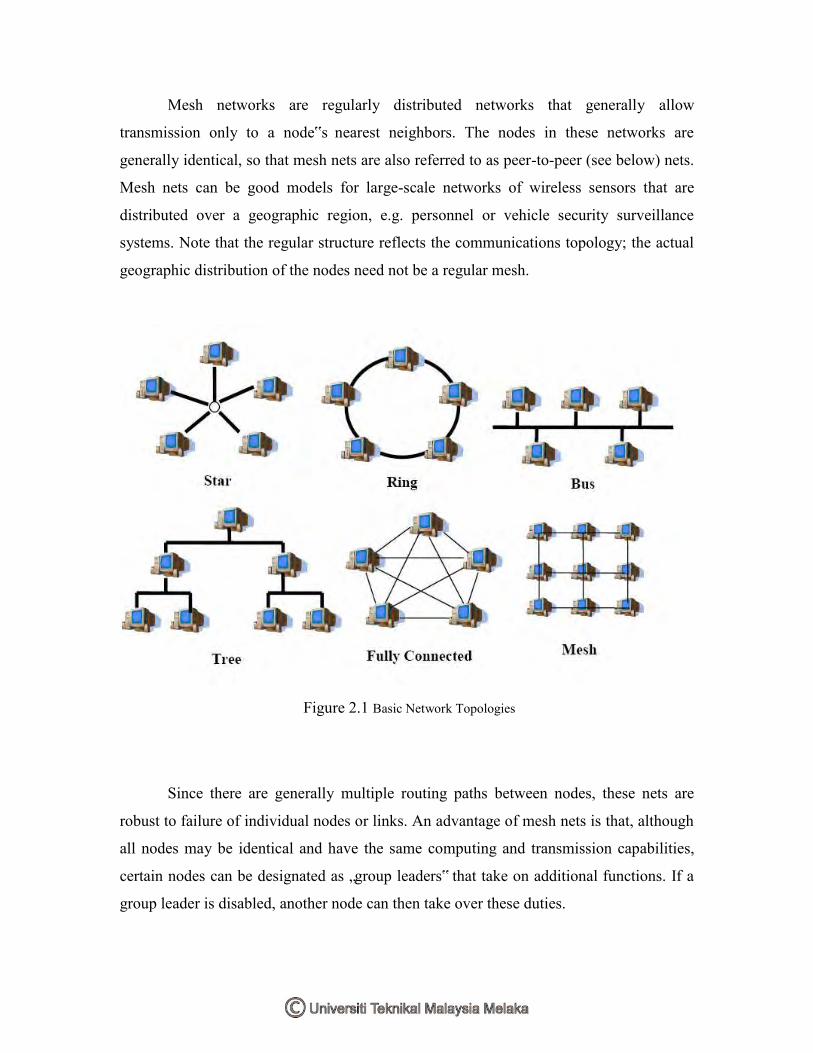
Mesh networks are regularly distributed networks that generally allow
transmission only to a node‟s nearest neighbors. The nodes in these networks are
generally identical, so that mesh nets are also referred to as peer-to-peer (see below) nets.
Mesh nets can be good models for large-scale networks of wireless sensors that are
distributed over a geographic region, e.g. personnel or vehicle security surveillance
systems. Note that the regular structure reflects the communications topology; the actual
geographic distribution of the nodes need not be a regular mesh.
Figure 2.1 Basic Network Topologies
Since there are generally multiple routing paths between nodes, these nets are
robust to failure of individual nodes or links. An advantage of mesh nets is that, although
all nodes may be identical and have the same computing and transmission capabilities,
certain nodes can be designated as „group leaders‟ that take on additional functions. If a
group leader is disabled, another node can then take over these duties.

All nodes of the star topology are connected to a single hub node. The hub
requires greater message handling, routing, and decision-making capabilities than the
other nodes. If a communication link is cut, it only affects one node. However, if the hub
is incapacitated the network is destroyed. In the ring topology all nodes perform the same
function and there is no leader node. Messages generally travel around the ring in a single
direction.
2.1.2 Sensor Node
A sensor node is a node in a wireless sensor network that is capable of performing
some processing, gathering sensory information and communicating with other connected
nodes in the network.
A sensor is hardware devices that produce measurable response to a change in a
physical condition like temperature and pressure. Sensors function is to sense or measure
physical data of the area to be monitored. The continual analog signal sensed by the
sensors is digitized by an Analog-to-digital converter and sent to controllers for further
processing. The characteristics and requirements of sensor node is should be in small
size, consume extremely low energy, operate in high volumetric densities, should be
autonomous and operate unattended, and be adaptive to the environment. As wireless
sensor nodes are micro-electronic sensor device, can only be equipped with a limited
power source of less than 0.5 Ah and 1.2 V.
Sensor
Unit
ADC CPU Graphical User Interface

Real World To User
Figure 2.2 Components of WSN
2.2 Zigbee
ZigBee is a worldwide open standard for wireless radio networks in the
monitoring and control fields. The standard was developed by the ZigBee Alliance (an
association of international companies) to meet the following principal needs:
a) low cost
b) ultra-low power consumption
c) use of unlicensed radio bands
d) cheap and easy installation
e) flexible and extendable networks
f) integrated intelligence for network set-up and message routing
Some of the above requirements are related - for example, the need for extremely
low power consumption is motivated by the use of battery-powered nodes which can be
installed cheaply and easily, without any power cabling, in difficult locations. Some of
the application areas that benefit from this type of network are described below.
2.2.1 Typical Application Areas
Application areas that are suitable for ZigBee networks are likely to have the
following characteristics or requirements:

a) low data rates (less than 250kbps)
b) nodes which are idle (not transmitting/receiving) for long periods
c) node locations where cables would be difficult or expensive to install
d) a need to modify the network (add, remove or move nodes) while in service
The following are typical application areas in which ZigBee provides a low-cost
solution (this is not an exhaustive list):
a) Commercial
Building and Home Automation: Electronic control within a building or home can
be implemented through wireless networks - example applications are HVAC
(heating, ventilation and air-conditioning), lighting, curtains/blinds, doors, locks
and home entertainment systems.
b) Security
Another important application within commercial buildings and the home is
security – both intruder and fire detection.
c) Healthcare
This field employs sensors and diagnostic devices that can be networked by
means of a wireless network. Applications include monitoring during healthcare
programs such as fitness training, in addition to medical applications such as
patient monitoring.
d) Vehicle Monitoring

Vehicles usually contain many sensors and diagnostic devices, and provide ideal
applications for wireless networks. A prime example is the use of pressure sensors
in tyres, which cannot be connected by cables.
e) Agriculture
Wireless networks can help farmers monitor land and environmental conditions in
order to optimist their crop yields. Such networks may require wide geographical
coverage, but ZigBee addresses this issue by offering network topologies that
allow the relaying of messages from node to node across the network.
Zigbee stack layer is technological standard created by the ZigBee Alliance for
control and sensor networks based on the IEEE 802.15.4 standard. It is part of wireless
sensor (WSN) family. This standard was setup the lower layer; Physical and Media
Access Control layers which is the hardware part. Together with IEEE standard there are
organization Zigbee Alliance as the software brand management for Zigbee. Zigbee
Alliance was setup the 3 upper layer; Network, Security, and Application layers. It using
the global common band of 2405 - 2480MHz with 16 channels in 5MHz interval.
There is always one node that takes a coordinating role in a network. It should be
the central node in a star topology and the top node in a tree or mesh topology. There
must also be nodes with the role of relaying messages from one neighboring node to
another.