


Languages
Pages
Legal


VWR® Collection ULT Chest Freezers
Version: 1Issued: January 15, 2015
INSTRUCTION MANUAL
VWR Number Model Number Manufacturing Number Size (cu ft) Box Voltage
-86°C FREEZERS
10160-738 VWRC0386A 5608 3 85 120V/60Hz
VWRC0386V 5609 3 85 230/50Hz
10160-740 VWRC1386A 5615 13 360 120V/60Hz
10160-742 VWRC1386D 5612 13 360 208-220V/60Hz
VWRC1386V 5613 13 360 230/50Hz
10160-744 VWRC2086A 5621 20 566 120V/60Hz
10160-746 VWRC2086D 5620 20 566 208-220V/60Hz
VWRC2086V 5623 20 566 230/50Hz
VWR International
MANUAL NUMBER 7055608
1 31653 1/15/15 Release 10 ccs
VERSION ECR/ECN DATE DESCRIPTION By
Preface
VWR Collection i
Part No. Description Qty
213F Key 2
380520 Neoprene Cap 2
510016 1/4-20 x 5-1/2” Bolt 2
195763 Retaining Clip 1
370563 Remote Alarm Connector 1
Packing List
Important installer and user information:A redundant temperature sensing device has been included in this ULTfreezer. This device is a type “T” thermocouple. For convenient access,the thermocouple (Figure 2-3) terminates in an interconnect jack(Figure 2-5) behind the base front cover. (May be located differently inchests. See Section 2.) It is strongly recommended that this thermocou-ple be attached to a redundant 24 hour 7 day monitoring system withalarm capabilities. Connecting the sensor to a monitoring and alarm sys-tem separate from the freezer provides the utmost in product safety,should the integral system fail. s
United States Europe
VWR International, LLC VWR International bvba
100 Matsonford Rd Researchpark Haasrode 2020
Radnor, PA 19087 Geldenaaksebaan 464
800-932-5000 B-3001 Leuven
http://www.vwr.com + 32 16 385011
http://be.vwr.com
Country of origin: United States

VWR Internationalii VWR Collection
Preface
Contains Parts and Assemblies
Susceptible to Damage by
Electrostatic Discharge (ESD)
CAUTION
Important Read this instruction manual. Failure to read, understand and follow the instructions in this manualmay result in damage to the unit, injury to operating personnel, and poor equipment performance. s
Caution All internal adjustments and maintenance must be performed by qualified service personnel. s
Material in this manual is for information purposes only. The contents and the product it describes are subjectto change without notice. VWR International makes no representations or warranties with respect to thismanual. In no event shall VWR be held liable for any damages, direct or incidental, arising out of or related tothe use of this manual.
Intended Use: The VWR Collection freezers (see cover page for specific model series) described in this manualare high performance units for professional use. These products are intended for use as cold storage in researchuse and as a general purpose laboratory freezer, storing samples or inventory at operating temperaturesbetween-50°C and -80°C.
It is not considered a medical device and has therefore not been registered with a medical device regulatorybody (e.g. FDA); that is, it has not evaluated for the storage of samples for diagnostic use or for samples to bere-introduced to the body.
This unit is not intended for use in classified hazardous locations, not to be used for the storage offlammable inventory.
©2015 VWR® International. All rights reserved.

VWR Collection iiiVWR International
Preface
Important operating and/or maintenance instructions. Read the accompanying text carefully.
Potential electrical hazards. Only qualified persons should perform procedures associated with thissymbol.
Equipment being maintained or serviced must be turned off and locked off to prevent possible injury.
Extreme temperature hazards, hot or cold. Use special handling equipment or wear special, protectiveclothing.
This equipment is marked with the crossed out wheeled bin symbol to indicate that this equipmentmust not be disposed of with unsorted waste.
Instead it's your responsibility to correctly dispose of your equipment at lifecycle -end by handling itover to an authorized facility for separate collection and recycling. It's also your responsibility todecontaminate the equipment in case of biological, chemical and/or radiological contamination, so asto protect from health hazards the persons involved in the disposal and recycling of the equipment.
For more information about where you can drop off your waste of equipment, please contact yourlocal dealer from whom you originally purchased this equipment.
By doing so, you will help to conserve natural and environmental resources and you will ensure thatyour equipment is recycled in a manner that protects human health.
4 Always use the proper protective equipment (clothing, gloves, goggles, etc.)
4 Always dissipate extreme cold or heat and wear protective clothing.
4 Always follow good hygiene practices.
4 Each individual is responsible for his or her own safety.

VWR Internationaliv VWR Collection VWR International
Preface
Do You Need Information or Assistance on VWR Scientific Products?
The VWR can provide information on pricing and give you quotations. We can take your order and provide delivery information on major equipment items or make arrangements to have your local sales representative contact your. Our products are listed on the internet and we can be contacted through our Internet home page.
1-800-932-5000 VWR, Toll Free, UShttp://www.vwr.com Internet Worldwide Web Home page
The VWR can supply technical information about proper setup, operation or troubleshooting of your equipment. We can fill your needs for replacement parts or
provide you with on-site service. We can also provide you with a quotation on our Extended Maintenance Program for your products.
Whatever VWR or Thermo products you need or use, we will be happy to discuss your applications. If you are experiencing technical problems, working together, we will help you locate the problem and, chances are, correct it yourself...over the telephone without a service call.
When more extensive service is necessary, we will assist you with direct factory trained technicians or a qualified service organization for on-the-spot repair. If your service need is covered by the VWR Scientific warranty, we will arrange for the unit to be repaired at our expense and to your satisfaction.
Regardless of your needs, VWR support by Thermo's professional telephone technicians is available to assist you Monday through Friday from 8:00a.m. to 6:30 p.m. Eastern Time. Please call or fax us at:
International customers, please contact your local distributor.
Sales Group
Product Service Group at Thermo
1-740-373-4763 Direct1-800-438-4851 Technical Services, Toll Free, U.S. and Canada1-740-373-4189 FAXHttp://www.vwr.com Internet Worldwide Web Home Page
Technical Services E-Mail [email protected]

Table of Contents
Product Specifications . . . . . . . . . . . . . . . . . . . . . . . . . . . . . . . . . . . . . . . .1-1
Overview . . . . . . . . . . . . . . . . . . . . . . . . . . . . . . . . . . . . . . . . . . . . . . . . . . . .2-1Control Panel Keys, Display, Indicators . . . . . . . . . . . . . . . . . . . . . . .2-5
Displays . . . . . . . . . . . . . . . . . . . . . . . . . . . . . . . . . . . . . . . . . . . . .2-7Install Freezer . . . . . . . . . . . . . . . . . . . . . . . . . . . . . . . . . . . . . . . . . . .2-7
Choose Location . . . . . . . . . . . . . . . . . . . . . . . . . . . . . . . . . . . . . . .2-8Install Wall Bumpers . . . . . . . . . . . . . . . . . . . . . . . . . . . . . . . . . . . .2-8RS-232 Communications . . . . . . . . . . . . . . . . . . . . . . . . . . . . . . . .2-8Remote Alarm Contacts and Analog Output . . . . . . . . . . . . . . . .2-10Attach Power Cord . . . . . . . . . . . . . . . . . . . . . . . . . . . . . . . . . . . .2-11Connect Unit to Electrical Power . . . . . . . . . . . . . . . . . . . . . . . . .2-11
Freezer Start-Up . . . . . . . . . . . . . . . . . . . . . . . . . . . . . . . . . . . . . . . .2-12Set Operating Temperature . . . . . . . . . . . . . . . . . . . . . . . . . . . . . .2-12Set High Temperature Alarm . . . . . . . . . . . . . . . . . . . . . . . . . . . .2-13Set Low Temperature Alarm . . . . . . . . . . . . . . . . . . . . . . . . . . . . .2-13Access Code . . . . . . . . . . . . . . . . . . . . . . . . . . . . . . . . . . . . . . . . .2-14
Run Mode . . . . . . . . . . . . . . . . . . . . . . . . . . . . . . . . . . . . . . . . . . . .2-14
Calibrate . . . . . . . . . . . . . . . . . . . . . . . . . . . . . . . . . . . . . . . . . . . . . . . . . . . .3-1Calibrate Control Probe . . . . . . . . . . . . . . . . . . . . . . . . . . . . . . . . . . .3-1
Temperature Stabilization Periods . . . . . . . . . . . . . . . . . . . . . . . . . .3-1
Configuration . . . . . . . . . . . . . . . . . . . . . . . . . . . . . . . . . . . . . . . . . . . . . . . .4-1Configuration Mode . . . . . . . . . . . . . . . . . . . . . . . . . . . . . . . . . . . . .4-1
High Alarm Test . . . . . . . . . . . . . . . . . . . . . . . . . . . . . . . . . . . . . . .4-1Low Alarm Test . . . . . . . . . . . . . . . . . . . . . . . . . . . . . . . . . . . . . . .4-1System Battery Test . . . . . . . . . . . . . . . . . . . . . . . . . . . . . . . . . . . .4-2BUS Battery Test . . . . . . . . . . . . . . . . . . . . . . . . . . . . . . . . . . . . . .4-2Display Temperature . . . . . . . . . . . . . . . . . . . . . . . . . . . . . . . . . . . .4-3Clear High Stage Alarm . . . . . . . . . . . . . . . . . . . . . . . . . . . . . . . . .4-3Set Access Code . . . . . . . . . . . . . . . . . . . . . . . . . . . . . . . . . . . . . . .4-3RS485 Address . . . . . . . . . . . . . . . . . . . . . . . . . . . . . . . . . . . . . . . .4-4Back Up System Type . . . . . . . . . . . . . . . . . . . . . . . . . . . . . . . . . . .4-4
Cold Excursions . . . . . . . . . . . . . . . . . . . . . . . . . . . . . . . . . . . . . . . . .4-4Warm Excursions . . . . . . . . . . . . . . . . . . . . . . . . . . . . . . . . . . . . . . . .4-4Reset Excursions . . . . . . . . . . . . . . . . . . . . . . . . . . . . . . . . . . . . . . . .4-4
VWR Collection vVWR International VWR Collection v
Section 1
Section 2
Section 4
Section 3
vi VWR Collection VWR International
Alarms . . . . . . . . . . . . . . . . . . . . . . . . . . . . . . . . . . . . . . . . . . . . . . . . . . . . . .5-1High Stage System Failure Alarm . . . . . . . . . . . . . . . . . . . . . . . . . .5-2Multiple Alarms . . . . . . . . . . . . . . . . . . . . . . . . . . . . . . . . . . . . . . .5-2Micro Board Failure Alarm . . . . . . . . . . . . . . . . . . . . . . . . . . . . . . .5-2Lost Communication . . . . . . . . . . . . . . . . . . . . . . . . . . . . . . . . . . .5-2
Error Messages . . . . . . . . . . . . . . . . . . . . . . . . . . . . . . . . . . . . . . . . . .5-3
Maintenance . . . . . . . . . . . . . . . . . . . . . . . . . . . . . . . . . . . . . . . . . . . . . . . .6-1Clean Cabinet Exterior . . . . . . . . . . . . . . . . . . . . . . . . . . . . . . . . . . .6-1Clean Air Filter . . . . . . . . . . . . . . . . . . . . . . . . . . . . . . . . . . . . . . . . .6-1Clean Condenser . . . . . . . . . . . . . . . . . . . . . . . . . . . . . . . . . . . . . . . .6-1
Cleaning the Water-cooled Condenser . . . . . . . . . . . . . . . . . . . . . .6-2Defrost Chamber . . . . . . . . . . . . . . . . . . . . . . . . . . . . . . . . . . . . . . . .6-2Clean Lid Gasket . . . . . . . . . . . . . . . . . . . . . . . . . . . . . . . . . . . . . . . .6-3Replace Battery(s) . . . . . . . . . . . . . . . . . . . . . . . . . . . . . . . . . . . . . . .6-3Check Battery(s) . . . . . . . . . . . . . . . . . . . . . . . . . . . . . . . . . . . . . . . .6-4Prepare Unit for Storage . . . . . . . . . . . . . . . . . . . . . . . . . . . . . . . . . .6-5
PREVENTIVE MAINTENANCE . . . . . . . . . . . . . . . . . . . . . . . . .6-6
Factory Installed Options . . . . . . . . . . . . . . . . . . . . . . . . . . . . . . . . . . . . . .7-1Back Up System (BUS) . . . . . . . . . . . . . . . . . . . . . . . . . . . . . . . . . . .7-1
Install Injection Assembly . . . . . . . . . . . . . . . . . . . . . . . . . . . . . . . .7-1Install Temperature Probe . . . . . . . . . . . . . . . . . . . . . . . . . . . . . . . .7-2Connect Probe/Solenoid Harness . . . . . . . . . . . . . . . . . . . . . . . . . .7-4BUS Control Panel . . . . . . . . . . . . . . . . . . . . . . . . . . . . . . . . . . . .7-4Configure Optional BUS (Back Up System) . . . . . . . . . . . . . . . . . .7-5Set Optional BUS Set Point . . . . . . . . . . . . . . . . . . . . . . . . . . . . . .7-5Disconnect Fitting Assembly, Transfer Hose . . . . . . . . . . . . . . . . .7-6
Chart Recorder . . . . . . . . . . . . . . . . . . . . . . . . . . . . . . . . . . . . . . . . .7-6Test the BUS . . . . . . . . . . . . . . . . . . . . . . . . . . . . . . . . . . . . . . . . .7-6Install Chart Paper . . . . . . . . . . . . . . . . . . . . . . . . . . . . . . . . . . . . .7-7Change Program . . . . . . . . . . . . . . . . . . . . . . . . . . . . . . . . . . . . . . .7-7Calibrate Chart Recorder . . . . . . . . . . . . . . . . . . . . . . . . . . . . . . . .7-7
Water-cooled Condenser . . . . . . . . . . . . . . . . . . . . . . . . . . . . . . . . . .7-8
Warranty Information . . . . . . . . . . . . . . . . . . . . . . . . . . . . . . . . . . . . . . . . .8-1
Handling Liquid Nitrogen . . . . . . . . . . . . . . . . . . . . . . . . . . . . . . . . . . . . .A -1Introduction . . . . . . . . . . . . . . . . . . . . . . . . . . . . . . . . . . . . . . . . . . .A -2Handling Liquid CO2 . . . . . . . . . . . . . . . . . . . . . . . . . . . . . . . . . . . . . . . . . .B-1First Aid . . . . . . . . . . . . . . . . . . . . . . . . . . . . . . . . . . . . . . . . . . . . . . . . . . . . .C-1
Table of Contents
Section 5
Section 6
Section 7
Section 8
Appendix

VWR Collection 1-1VWR International
Section 1 Product Specifications
Temperature Range -50°C (-58°F) to -86°C (-123°F) in an 18°C to 28°C * (64.4°F to 82.4°F) ambient
Capacity12.7 cu. ft. (360 liters)
20.0 cu. ft. (566.3 liters)
Refrigeration Cascade system, (2) hermetically-sealed compressors
InsulationCFC-free, foamed-in-place urethane: minimum 5.0" (12.7cm) cabinet; 2.0" (5.0cm) lid;
1.0" (12.5cm) sub-lids
Electrical - nominal voltage ±10% 208-230VAC, 1 PH, 60 Hz, 12 FLA 230VAC, 1 PH, 50 Hz, 12 FLA 120VAC, 1 PH, 60 Hz, 16 FLA
Breaker Requirements15 Amp Dedicated Circuit, 15 Amp Time Delay Breaker
15 Amp Dedicated Circuit, 15 Amp Time Delay Breaker
20 Amp Dedicated Circuit,20 Amp Time Delay Breaker
Temperature Range -50°C (-58°F) to -86°C (-123°F) in an 18°C to 28°C * (64.4°F to 82.4°F) ambient
Capacity 3.0 cu. ft. (84.9 liters)
Refrigeration Cascade system, (2) hermetically-sealed compressors
InsulationCFC-free, foamed-in-place urethane: minimum 5.0" (12.7cm) cabinet; 2.0" (5.0cm) lid;
1.0" (12.5cm) sub-lids
Electrical - nominal voltage ±10% 120VAC, 1 PH, 60 Hz, 10.5 FLA 230VAC, 1 PH, 50 Hz, 5.4 FLA
Breaker Requirements15 Amp, 120VAC, Dedicated Circuit, 15 Amp Time Delay Breaker
15 Amp, 230VAC, Dedicated Circuit,15 Amp Time Delay Breaker
1-2 VWR Collection VWR International
Section 1Product Specifications
CertificationsDeclaration of Conformity is available from the factory
Safety SpecificationsIndoor Use OnlyAltitude - up to 2,000 metersTemperature - 5°C to 43°CHumidity - Maximum RH 80% for temperatures up to 31°C, decreas-ing linearly to 50% RH at 40°CMains Supply Fluctuations - Mains supply voltage fluctuations not toexceed ±10% of the nominal voltageInstallation Category II 1
Pollution Degree 2 2
Class of Equipment
1 Installation category (overvoltage category) defines the level of transient overvoltage whichthe instrument is designed to withstand safely. It depends on the nature of the electricity supplyand its overvoltage protection means. For example, in CAT II which is the category used forinstruments in installations supplied from a supply comparable to public mains such as hospitaland research laboratories and most industrial laboratories, the expected transient overvoltage is2500V for a 230V supply and 1500V for a 120V supply.
2 Pollution degree describes the amount of conductive pollution present in the operatingenvironment. Pollution degree 2 assumes that normally only non-conductive pollution such asdust occurs with the exception of occasional conductivity caused by condensation.

VWR Collection 2-1VWR International
Section 2 Overview
Figures 2-1 and 2-2 show the front view of the freezer and indicate thefollowing freezer components:
• Control Panel - keypad, displays and indicators.
• BUS (Optional Back Up System) panel.
• Optional temperature recorder (7 day, one pen) or datalogger.
• Keylock - keyed lid lock.
Figure 2-1. Front View Models 5608, 5609
Figure 2-2. Front View Models 5612, 5613, 5615, 5620, 5621, 5623
2-2 VWR Collection VWR International
Section 2Overview
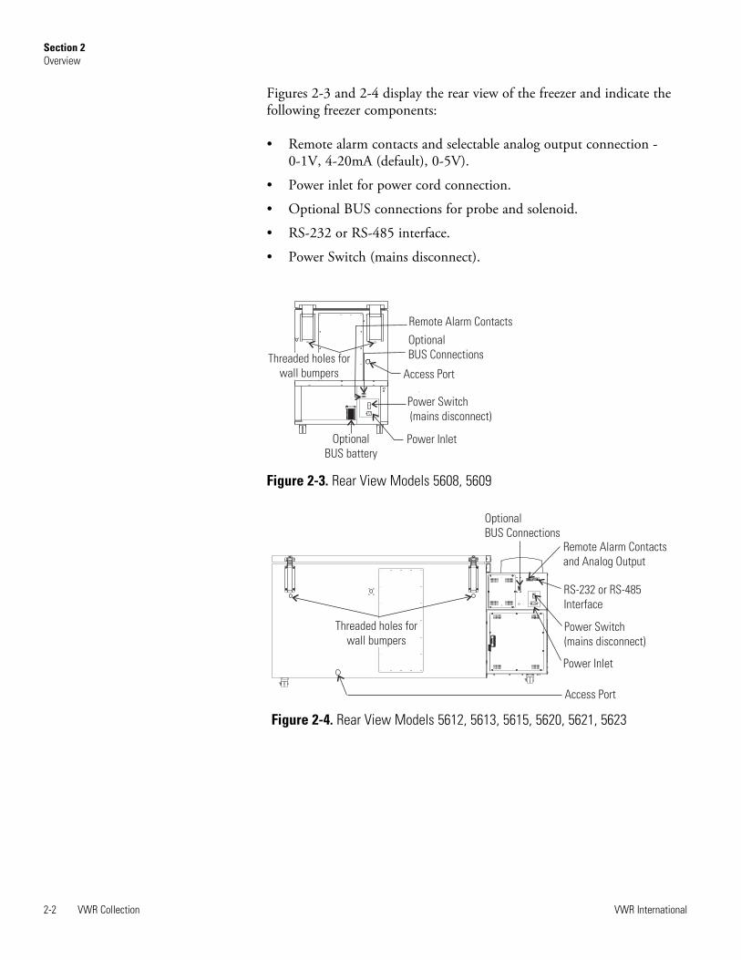
Figures 2-3 and 2-4 display the rear view of the freezer and indicate thefollowing freezer components:
• Remote alarm contacts and selectable analog output connection - 0-1V, 4-20mA (default), 0-5V).
• Power inlet for power cord connection.
• Optional BUS connections for probe and solenoid.
• RS-232 or RS-485 interface.
• Power Switch (mains disconnect).
Optional
BUS battery
I
O
Optional
BUS Connections
Remote Alarm Contacts
Power Switch
(mains disconnect)
Power Inlet
Threaded holes for
wall bumpers Access Port
Figure 2-3. Rear View Models 5608, 5609
RS-232 or RS-485
Interface
Remote Alarm Contacts
and Analog Output
Optional
BUS Connections
Power Switch
(mains disconnect)
Power Inlet
Access Port
Threaded holes for
wall bumpers
Figure 2-4. Rear View Models 5612, 5613, 5615, 5620, 5621, 5623

VWR Collection 2-3VWR International
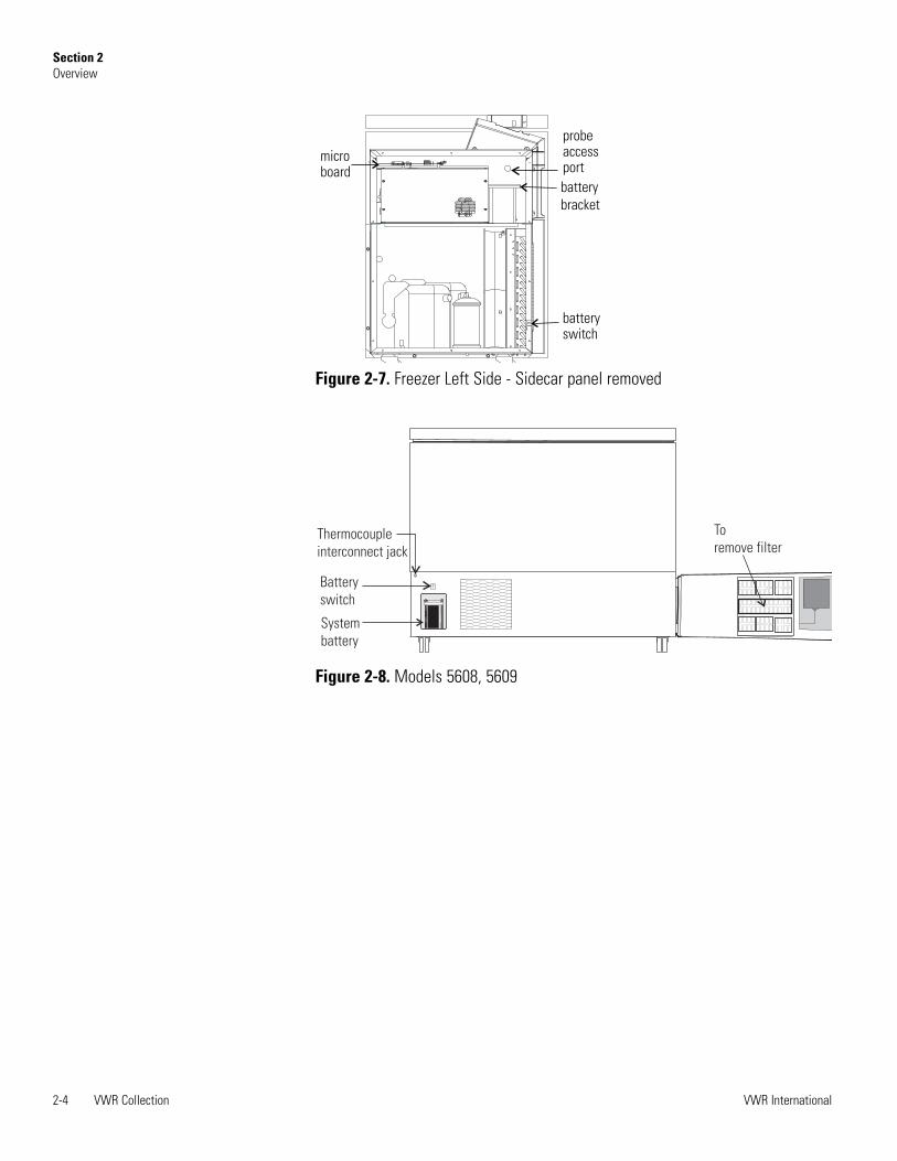
Section 2Overview
The probe cover houses the control, optional recorder, Model 1535 alarm,or BUS probes.
Figures 2-6, 2-7, and 2-8 indicate the following components:
• Freezer filter location
• Battery power switch (freezer and BUS)
• Thermocouple receptacle
• Battery mounting bracket
• Freezer and optional BUS battery
Figure 2-5. Probe Cover
aaaaaaaaaaaaaaaaaaaaaaaaaaaaaaaaaaaaaaaaaaaaaaaaaaaaaaaaaaaaaaaaaaaaaaaaaaaaaaaaaaaaaaaaaaaaaaaaaaaaaaaaaaaaaaaaaaaaaaaaaaaaaa
C F
%RH
Alarm
Sensor
To remove
filter
Thermocouple
interconnect jack
O
Battery
Switch
Condenser
Figure 2-6. Models 5612, 5613, 5615, 5620, 5621, 5623
2-4 VWR Collection VWR International
Section 2Overview
microboard
battery
bracket
batteryswitch
probeaccessport
Figure 2-7. Freezer Left Side - Sidecar panel removed
O
aaaaaaaaaaaaaaaaaaaaaaaaaaaaaaaaaaaaaaaaaaaaaaaaaaaaaaaaaaaaaaaaaaaaaaaaaaaaaaaaaaaaaaaaaaaaaaaaaaaaaaaaaaaaaaaaaaaaaaaaO
System
battery
Battery
switch
Thermocouple
interconnect jack
To
remove filter
Figure 2-8. Models 5608, 5609

1. Mode select switch - Used to select Run, Settings, Calibrate andSystem Configuration Modes.
2. Temperature display - Displays temperature in degrees Celsius.
3. Alarm indicator - Light pulses on/off during an alarm condition of thecabinet.
4. Mute - Silences the audible alarm.
5. Low Battery - indicates a low battery condition of the freezer battery.
6. Hot Condenser - indicates a hot condenser condition.
7. Message Center - displays system status and alarms.
8. Scroll for Parameters arrows - moves the operator through the choicesof the selected mode.
9. Up and down arrows - Increases or decreases values, toggles betweenchoices.
10. Enter arrow - Stores the value into computer memory.
VWR Collection 2-5VWR International
Section 2Overview
Figure 2-9. Control Panel Keys, Display and Indicators
Control Panel Keys,Display, Indicators
MuteModeAlarmIndicator
Temperature Display
Enter ArrowUp and Down ArrowsScroll for Parameters Arrows
Low Battery
HotCondenser

VWR Collection freezers have four basic modes which allow freezer setup:Run, Settings, Calibrate and Configuration.
Run is the default mode which the freezer will normally be in duringoperation.
Settings is used to enter system set points for freezer operation.
Calibrate is used to calibrate various system parameters.
Configuration allows for custom setup of various options.
The chart below shows the selections under each of the modes.
2-6 VWR Collection VWR International
Section 2Overview
Table 2-1. Modes of Operation
Run Settings Calibrate Configuration
Default ModeSystem Ok
Control Set Point Control Probe High Alarm Test
Line Voltage High Alarm Set Point Optional SampleProbe Low Alarm Test
Compensated Voltage Low Alarm Set Point System Battery Test
HSHX Temperature Optional Back UpSystem Set Point BUS Battery Test
Display Temperature
Clear High StageAlarm
Set Access Code
RS485 Address
BUS type CO2 or LN2
Cold Excursion
Warm Excursion
Reset Excursion
Panel Keys, Display,Indicators (cont.)

Scroll for Parameters arrows: Steps the operatorthrough the parameters of SETTINGS, CALIBRATEand CONFIGURATION Modes. The right arrow goesto the next parameter, the left arrow returns to theprevious parameter.
Up arrow: Increases or toggles the parameter value thathas been selected in the SETTINGS, CALIBRATE,and CONFIGURATION Modes.
Enter arrow: Must press enter arrow key to save tomemory all changed values.
Down arrow: Decreases or toggles the parameter valuesthat have been selected in the SETTINGS,CALIBRATE and CONFIGURATION Modes.
Mute key: Press to silence the audible alarm. See Section 4 foralarm ringback times.
There are two displays on the control panel. The temperature displayshows the temperature in degrees Celsius. The message center displays thesystem status (Mode) at all times. The message SYSTEM OK displaysduring normal operation. Alarm messages are displayed if the systemdetects an alarm condition. See Section 5 - Alarms.
To remove the freezer from the pallet, use a 1/2" wrench to remove all thebolts securing the shipping bracket to the pallet.
Note If tipped more than 45°, allow the unit to set upright for 24 hoursbefore start up. s
Remove the shipping bracket. Remove the ramp boards from the palletand place the slotted end over the ramp brackets on the pallet. Thesupport blocks on the ramps will be facing down. Before moving thefreezer, make sure the casters are unlocked and moving freely. Align thecaster with the ramp boards. Use adequate personnel to roll the freezer offthe pallet.
VWR Collection 2-7VWR International
Section 2Overview
Displays
Figure 2-10. Message Center
Install Freezer
Panel Keys, Display,Indicators (cont.)

The freezer can be easily pushed to the desired approved location, asdescribed previously. When the freezer is in position, set the front casterbrakes.
Note Do not move the freezer with the product load inside. s
Caution If the factory installed option water-cooled condenser is present,do not turn the freezer on without water connected and flowing. Damageto the refrigeration system could occur within 5 minutes if water is notconnected and flowing on unit start-up. Refer to Section 6. s
Locate the freezer on a firm, level surface in an area with an ambienttemperature between 18°C and 28°C. Provide ample room to reach themains disconnect switch (power switch) located on the rear of the freezer.
Caution For proper ventilation and airflow, a minimum clearance of 5” atthe rear and front and a clearance of 8” on the side of the freezer isrequired. Allow adequate space for lid opening. If ambient increases above36°C, clearance at the rear of the cabinet must be increased to 8”. s
The parts bag, located inside the cabinet, contains the following parts.
Install the bolts into the pre-tapped holes on the back of the compressorsection. Install a neoprene cap on each bolt. Refer to Figure 1-2 for thelocations of the pre-tapped holes.
VWR Collection freezers have a data communications interface. Thefactory default setting is RS-232.
The wiring identification for the interfaceis shown in Figure 2-11. One nine pin, sub"D" style connector is located on the backof the freezer. See Figure 2-2 for thelocation of the connector on the freezer.
2-8 VWR Collection VWR International
Section 2Overview
Quantity Stock # Description Purpose
2 510016 1/4-20 x 5-1/2” Bolt Wall Bumper
2 380520 Neoprene Cap Cap Protector
Choose Location
Install Wall Bumpers
RS-232 Communications
Figure 2-11. RS-232 Interface
Install Freezer(continued)
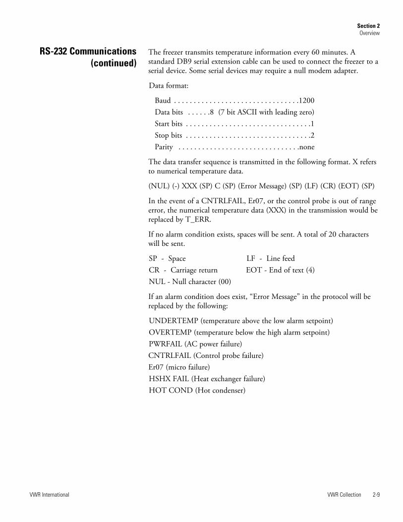
The freezer transmits temperature information every 60 minutes. Astandard DB9 serial extension cable can be used to connect the freezer to aserial device. Some serial devices may require a null modem adapter.
Data format:
Baud . . . . . . . . . . . . . . . . . . . . . . . . . . . . . . . .1200Data bits . . . . . .8 (7 bit ASCII with leading zero)Start bits . . . . . . . . . . . . . . . . . . . . . . . . . . . . . . . .1Stop bits . . . . . . . . . . . . . . . . . . . . . . . . . . . . . . . .2Parity . . . . . . . . . . . . . . . . . . . . . . . . . . . . . . .none
The data transfer sequence is transmitted in the following format. X refersto numerical temperature data.
(NUL) (-) XXX (SP) C (SP) (Error Message) (SP) (LF) (CR) (EOT) (SP)
In the event of a CNTRLFAIL, Er07, or the control probe is out of rangeerror, the numerical temperature data (XXX) in the transmission would bereplaced by T_ERR.
If no alarm condition exists, spaces will be sent. A total of 20 characterswill be sent.
SP - Space LF - Line feedCR - Carriage return EOT - End of text (4)NUL - Null character (00)
If an alarm condition does exist, “Error Message” in the protocol will bereplaced by the following:
UNDERTEMP (temperature above the low alarm setpoint)OVERTEMP (temperature below the high alarm setpoint)PWRFAIL (AC power failure)CNTRLFAIL (Control probe failure)Er07 (micro failure)HSHX FAIL (Heat exchanger failure)HOT COND (Hot condenser)
VWR Collection 2-9VWR International
Section 2Overview
RS-232 Communications(continued)

VWR Collection freezers have remote alarm contacts and analog output.See Figures 2-3 and 2-4 for the location of the remote alarm contacts. Theremote alarm connector is located in the parts bag provided with themanual. It must be installed if connecting the freezer to an alarm system.After installing the wiring from the alarm system to the connector, installthe connector to the freezer microboard and secure with the two screwsprovided. The remote alarm provides a NO (normally open) output, a NC(normally closed) output and COM (common). The contacts will trip on apower outage, high temperature alarm or low temperature alarm. Theywill also trip on high stage, control probe and micro board failures. Figure2-12 shows the remote contacts in alarm state.
The analog output function allows the freezer to output signalsrepresenting the temperature of the freezer cabinet. The factory defaultsetting is 4-20 mA. Refer to Table 2-2 for output specifications.
2-10 VWR Collection VWR International
Section 2Overview
Remote Alarm Contactsand Analog Output
Figure 2-12. Remote Alarm Contacts
4-20 mA 0-1V 0-5V
Temperature -100 to +50°C -100 to +50°C -100 to +50°C
Table 2-2. Analog Output Specifications
IMPORTANT USER INFORMATION
CAUTION! Stored product should be protected
by a redundant 24 hour/day monitoring system
with alarm capability. An interconnect jack and
thermocouple are installed for centralized
monitoring, should on-board system fail.

Insert the power cord into the power inlet module. Place the retainingbracket (P/N 195763) over the connector. Tighten retaining screws tosecure.
Note See the serial tag on the side of the unit for electrical specifications orrefer to the electrical schematics in this manual. s
Caution If the factory installed option water-cooled condenser is present,do not turn the freezer on without water connected and flowing. Damageto the refrigeration system could occur within 5 minutes if water is notconnected and flowing on unit start-up. Refer to Section 6. s
The freezer should be operated on a dedicated, grounded service. Checkthe voltage rating on the serial tag of the unit and compare it with theoutlet voltage. Then, with the power switch turned off, plug the line cordinto the wall outlet.
First, turn on the freezer power switch. Then open the lower front door bygrasping the bottom left corner. Locate the battery switch (Figure 1-4) andturn it to Standby mode ( ). During initial freezer start-up, the systembattery may require charging and the Low Battery message may appear inthe message center.
Note Ensure the battery switch is turned to Standby mode ( ). Therechargeable batteries require 36 hours to charge at initial start-up. A “LowBattery” alarm may occur until the batteries are fully charged. Should apower failure occur during the initial start-up period, the electronics willhave limited operation. s
VWR Collection 2-11VWR International
Section 2Overview
Attach Power Cord
Connect Unit to ElectricalPower
Figure 2-13. Power Cord Attachment

With the freezer properly installed and connected to power, system setpoints can be entered. The following set points can be entered in Settingsmode: Control temperature, high temperature alarm set point, lowtemperature alarm set point, and (optional) BUS set point. Defaultsettings are shown in the table below. See Chart 2-1 for more detail.
Note If the set point is changed and the low temperature and hightemperature alarms are set 10° from the set point, the alarm set points willbe adjusted automatically to maintain a distance of at least 10° from setpoint. s
Caution If the factory installed option water-cooled condenser is present,do not turn the freezer on without water connected and flowing. Damageto the refrigeration system could occur within 5 minutes if water is notconnected and flowing on unit start-up. Refer to Section 6. s
The freezer has an operating temperature range of -50°C to -86°C,depending on ambient temperature. The freezer is shipped from thefactory with a temperature set point of -80°C. To change the operatingtemperature set point:
1. Press the Mode key until the Settings indicator lights.
2. Press the right arrow until “SET PT = -XX” is displayed in the messagecenter.
3. Press the up/down arrow key until the desired temperature set point isdisplayed.
4. Press Enter to save the set point.
5. Press the Mode key until the Run indicator lights for Run mode orpress the right/left arrow keys to go to next/previous parameter.
If no control keys are pressed, the freezer will automatically return to RUNmode after 5 minutes.
2-12 VWR Collection VWR International
Section 2Overview
Freezer Start-Up
Set OperatingTemperature
Control Set Point -80°C
High Temperature Alarm -70°C
Low temperature alarm -90°C
Optional BUS Set Point -60°C

The high temperature alarm activates an audible/visual warning when thefreezer chamber temp reaches or exceeds the high temp alarm set point.
To set the high temperature alarm set point:
1. Press the Mode key until the Set indicator lights.
2. Press right arrow until “HI ALM = -XX” displays in message center.
3. Press the up or down arrow key until the desired high temperaturealarm set point is displayed.
4. Press Enter to save the setting.
5. Press the Mode key until the Run indicator lights or press the right orleft arrow to go to the next or previous parameter.
If no control keys are pressed, the freezer will automatically return to RUNmode after 5 minutes.
Note The high alarm set point must be set at least 5°C from the controlset point. s
Note At initial start-up, the high temperature alarm is disabled until thecabinet reaches set point or 12 hours elapse. s
The low temperature alarm activates an audible/visual warning when thefreezer chamber temp reaches or decreases below low temp alarm set point.
To set the low temperature alarm set point:
1. Press the Mode key until the Settings indicator lights.
2. Press right arrow until “LO ALM = -XX” displays in message center.
3. Press the up or down arrow key until the desired low temperaturealarm set point is displayed.
4. Press Enter to save the setting.
5. Press the Mode key until the Run indicator lights or press the right orleft arrow to go to the next or previous parameter.
If no control keys are pressed, the freezer will automatically return to RUNmode after 5 minutes.
Note Low alarm setpoint must be set at least 5°C from control setpoint. s
VWR Collection 2-13VWR International
Section 2Overview
Set High TemperatureAlarm
Set Low TemperatureAlarm

An access code can be set to prevent unauthorized change of settings inCalibrate, Configuration and Settings mode. (An access code of 000 isrequired to make changes.) If the access code is not at the default 000, youcan not leave RUN mode without entering a code. See Section 4,Configuration for instructions on modifying the access code.
Run mode is the default mode for the freezer. The run mode displays thecabinet temperature on the temperature display and ‘SYSTEM OK’ on themessage center under normal operating conditions. In addition, the Runmode allows display of the following information:
LINE VOLTAGECOMPENSATED VOLTAGEHSHX TEMPERATURE (heat exchange temperature)
This information is scrolled individually by pressing the right arrow key. Ineach case, the message center returns to SYSTEM OK in 10 seconds if nokeys are pressed.
2-14 VWR Collection VWR International
Section 2Overview
Access Code
Run Mode

VWR Collection 2-15VWR International
Section 2Overview


VWR Collection 3-1VWR International
Section 3 Calibrate
Once the freezer has stabilized, the control probe may need to becalibrated. Calibration frequency is dependent on use, ambient conditionsand accuracy required. A good laboratory practice would require at least anannual calibration check. On new installations, all parameters should bechecked after the stabilization period.
Note Before making any calibration or adjustments to the unit, it isimperative that all reference instruments be properly calibrated. s
Plug a type T thermocouple reader into the receptacle located inside thelower door (see Figures 2-4 and 2-6). Compare the control temperatureset point to the temperature of the measuring device. See Chart 3-1 at theend of this section for more detail.
1. Press the Mode key until the Calibrate indicator lights.
2. Press the right arrow until “CONT T = -XX.X” appears in the messagecenter.
3. Press up/down arrow to match the display to calibrated instrument.
4. Press Enter to store calibration.
5. Press the Mode key to return to Run or the right/left arrow to go tonext/previous parameter.
Startup - Allow 12 hours for the temperature in the cabinet to stabilizebefore proceeding.
Already Operating - Allow at least 2 hours after the display reaches setpoint for temperature to stabilize before proceeding.
Note During calibration, the temperature display will not be available. s
If no keys are pressed for approximately five minutes while in calibrationmode, the system will reset to Run mode.
Calibrate ControlProbe
Temperature StabilizationPeriods

3-2 VWR Collection VWR International
Section 3Calibrate

VWR Collection 4-1VWR International
Section 4 Configuration
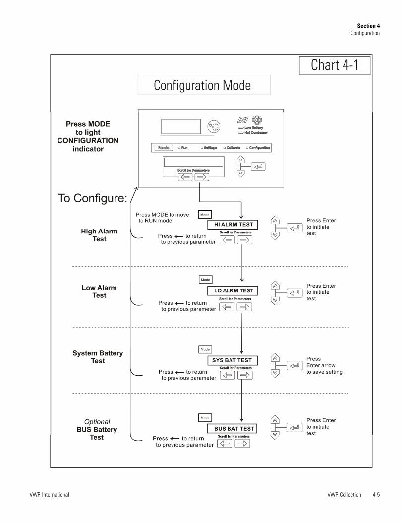
Configuration Mode is used for testing and custom setup of the freezer.The configuration functions listed and described below may not benecessary in all applications, but are available if needed. See Chart 4-1 formore detail.
The high alarm test is used to verify that the high alarm will activate,should the freezer temperature equal or exceed the high alarm set point.
1. Press the Mode key until the Configuration indicator lights.
2. Press the right arrow until HI ALRM TEST is displayed in themessage center.
3. Press Enter to initiate the test.
The temperature on the display will begin to increase until the high alarmset point has been reached. The audible alarm will sound and the alarmindicator will flash. Press the Mute key to silence the alarm.
The low alarm test is used to verify the that low alarm will activate, shouldthe freezer temperature equal or become less than the low alarm set point.
1. Press the Mode key until the Configuration indicator lights.
2. Press the right arrow until LO ALRM TEST is displayed in themessage center.
3. Press Enter to initiate the test.
The temperature on the display will begin to decrease until the low alarmset point has been reached. The audible alarm will sound and the alarmindicator will flash. Press the Mute key to silence the alarm.
High Alarm Test
Low Alarm Test

4-2 VWR Collection VWR International
Section 4Configuration
To test the charge of the freezer battery:
1. Press the Mode key until the Configuration indicator lights.
2. Press the right arrow until SYS BAT TEST is displayed in the messagecenter.
3. Press Enter to initiate the test.
TESTING BATT will display during the testing period. Upon completionof the test the message center will display BATT GOOD or BATT FAILWhen a test is failed, the audible alarm will sound, the alarm indicator andthe Low Battery indicator will light. Press the Mute key and the alarmindicator will go off. The Low Battery light will stay on until a futurebattery test is performed and passed.
To test the charge of the BUS battery:
1. Press the Mode key until the Configuration indicator lights.
2. Press the right arrow until BUS BAT TEST is displayed in the messagecenter.
3. Press Enter to initiate the test.
TESTING BATT will display during the testing period. Upon completionof the test the message center will display BBAT GOOD or BBAT FAIL Ifthis test fails, the audible alarm will sound, the alarm indicator and theLow Battery indicator will light. Press the Mute key. The audible alarmand alarm indicator will go off. The Low Battery light will stay on. If thetest fails, it is recommended to replace the BUS battery.
System Battery Test
BUS Battery Test

VWR Collection 4-3VWR International
Section 4Configuration
This function, only available on freezers with the optional sample probe,allows the user to select which temperature is displayed in the temperaturedisplay window. The options are CONTROL or SAMPLE.
1. Press the Mode key until the Configuration indicator lights.
2. Press the right arrow until DISP CONTROL or DISP SAMPLE isdisplayed in the message center.
3. Press up/down arrow to toggle between the two display selections.
4. Press Enter to save.
If control probe is selected, the temperature display will be oncontinuously. If sample probe is selected, the temperature display will bepreceded with a letter ‘S’.
Should a high stage alarm have occurred, it may become necessary to clearthe alarm condition after the condition has been corrected.
1. Press the Mode key until the Configuration indicator lights.
2. Press the right arrow until CLR HS ALARM is displayed in themessage center.
3. Press Enter to clear the alarm.
To set the Access Code:
1. Press the Mode key until the Configuration indicator lights.
2. Press the right arrow until “SET ACC CODE” is displayed in themessage center.
3. Press Enter.
4. The message center will display ACC CODE = 000. Press the up ordown arrow key until the desired access code is displayed (000 - 999).Press the left or right arrow key to select digit 1, 2, 3.
Note The left and right arrow keys are used to move from the first throughthe third digits within the access code. s
5. Press Enter to save the setting
6. Press the Mode key until the Run indicator lights.A 3-digit AccessCode can be entered to avoid unauthorized personnel from changingthe set points, calibration, or configuration. A setting of 000 willbypass the access code. The factory setting is 000.
Display Temperature
Clear High Stage Alarm
Set Access Code

If the freezer is configured for RS-485 communications, it will need tohave a unique identification address. This address is set through theConfiguration mode.
1. Press the Mode key until the Configuration indicator lights.
2. Press the right arrow until RS485ADDR is displayed in the messagecenter.
3. Press Enter. The message center will display 485 ADDR XX.
4. Press up/down arrow to select the appropriate address for the freezer(1 - 24).
5. Press Enter to save.
This function, which is only available on freezers with the optional BUS(back up system), allows the user to select which type of gas is injected intothe freezer chamber. The options are CO2 and LN2.
1. Press the Mode key until the Configuration indicator lights.
2. Press the right arrow until BUS TYPE CO2 or BUS TYPE LN2 isdisplayed in the message center.
3. Press up/down arrow to toggle between the two display selections.
4. Press Enter to save.
This function displays the coldest temperature recorded by the controlprobe.
This function displays the warmest temperature recorded by the controlprobe.
This function resets the cold and warm excursions.
4-4 VWR Collection VWR International
Section 4Configuration
RS485 Address
Back Up System Type
Cold Excursions
Warm Excursions
Reset Excursions
VWR Collection 4-5VWR International
Section 4Configuration

4-6 VWR Collection VWR International
Section 4Configuration

VWR Collection 4-7VWR International
Section 4Configuration


VWR Collection 5-1VWR International
Section 5 Alarms
The VWR Collection freezer alarm system is shown below. When analarm is active, a message appears in the LED message center. Press theMute key to silence the audible alarm for the ringback period. The visualalarm continues until the freezer returns to a normal condition. The alarmsare momentary alarms only. If an alarm condition occurs and then returnsto normal, the freezer automatically clears the alarm condition and themessage center.
All alarm delays and ringback times are +30 seconds.*The automatic battery test runs immediately on start-up, then every 8 hours thereafter.
Description Message Delay Ringback Relay
No alarm condition exists SYSTEM OK ---- ---- ----
Power Failure POWER FAIL 1 min. 15 min. Yes
High Temperature Alarm TEMP IS HIGH 1 min. 15 min. Yes
Low Temperature Alarm TEMP IS LOW 1 min. 15 min. Yes
Door Ajar DOOR IS OPEN 1 min. 15 min. No
Low Battery* LOW BATTERY 1 min. 12 hours No
Low BUS Battery (optional) LOW BUS BATT 1 min. 15 min. No
Control Probe Failure CNT PRB FLT 1 min. 15 min. Yes
Heat Exchanger Probe Failure HSHX PRB FLT 1 min. 15 min. No
Condenser Probe COND PRB FLT 1 min. 15 min. No
Sample Probe Failure (optional) SMPL PRB FLT 1 min. 15 min. No
High Stage System Failure HS SYST FAIL 1 min. 15 min. Yes
Condenser Hot Condition HOT CONDENSR 1 min. none No
Wrong Power WRONG POWER 0 min. none Yes
Micro Board Failure MICRO FAIL 0 min. 15 min. Yes

5-2 VWR Collection VWR International
Section 5Alarms
This condition is created when the high stage compressor and fans run for30 minutes and are not capable of cooling the interstage heat exchanger tothe proper temperature. Under this condition, the high stage compressorand fans will turn off after 30 minutes and an audible and visual alarm willoccur along with the "HS SYST FAIL" message in the LED messagecenter.
When multiple alarm conditions occur, active messages are displayed in themessage center one at a time, updating at 5 second intervals. Pressing Muteduring multiple alarms causes all active alarms to be silenced and to ringback in 15 minutes.
An internal communication failure has occurred with the micro board.During this alarm, the compressor(s) attempt to run continuously.However, with this type of failure, freezer operation becomesundependable.
Communication between the micro board and the display board has beenlost. Under this condition, the visual alarm flashes along with dashes in thetemperature display (----). In addition, ‘LOST COMM’ flashes in themessage center. Contact Technical Services.
High Stage System FailureAlarm
Multiple Alarms
Micro Board FailureAlarm
Lost Communication

VWR Collection 5-3VWR International
Section 5Alarms
Error MessagesError High End Message Notes
Er00 “INV. MODEL”
Name: Improper model selected.Description: Indicates that DIP SW3 has not selected a proper model or can’t be accessed properly.Response: Display shows “Er00” and will not start-up until a proper model is selected. Contact TechnicalServices.
ErA1 “ NO FREQUENCY” This error condition will prevent peripherals (fans, compressors, etc.) from powering up with the incorrectvoltage.Name: Voltage/Frequency failureDescription: Indicates the measured RMS line voltage did not agree with the logic level sensed by themicros provided by the installed high voltage PCB; or the measured RMS voltage is not within a tolerablerange (<180VAC < 270 for 230VAC unit / <85 VAC < 160 for 115VAC unit); or the frequency measured over 10cycles was not within a tolerable range (55 Hz < Freq < 70 Hz for 60 Hz units / 40 Hz < Freq < 55 Hz for 50 Hzunits)Response: This condition is checked at power on reset and if it is active the unit will NOT power up. Theunit will indefinitely display “Er_1” in the display and continue to monitor the frequency and voltage.Furthermore, the audible alarm will sound. Other startup error messages may be displayed prior to this mes-sage; however, the system will stop the startup sequence for this condition.ErA1 .. No pulses (zero crossings) detected to determine frequency (50 / 60 Hz)ErC1 .. Frequency detected is below 50 HzErd1 .. Frequency detected is above 60 Hz (Possible noise spikes on supply voltage)ErE1 .. Unit is 230V and the voltage detected is below the low limit (180VRMS)ErF1 .. Unit is 230V and the voltage detected is above the high limit (260VRMS)Erg1 .. Unit is 115V and the voltage detected is below the low limit (85VRMS)ErH1 .. Unit is 115V and the voltage detected is above the high limit (160VRMS)
ErC1 “FREQ <50Hz”
Erd1 “FREQ >60Hz”
ErE1 “VAC < 180V”
ErF1 “VAC > 260V”
Erg1 “VAC < 85V”
ErH1 “VAC > 160V”

5-4 VWR Collection VWR International
Section 5Alarms
Error(cont.) High End Message Notes
Er02 “CNT PRB FLT”
Name: Control (Cabinet) Sensor FailureDescription: This condition indicates that the control sensor has failed to produce a valid reading for >12consecutive reads (~60 seconds).Response: The unit will stage both compressors on (if necessary) and the unit will attempt to head to bot-tom out. If the sensor recovers, the system will begin to operate normally and respond to the temperaturefeedback. The remote alarm contacts will become active regardless of the key position for this mode of fail-ure. ‘Er02’ will be added to the main display queue and the last valid cabinet temperature value will not bedisplayed
Er03 “HSHX PRB FLT”
Name: Heat Exchange Sensor FailureDescription: This condition indicates that the heat exchange sensor has failed to produce a valid readingfor >12 consecutive reads (~60 seconds).Response: The display will show “Er03” only when the button sequence to read the heat exchange sensoris depressed.
Er05 N/A
Name: Display Firmware Integrity FailureDescription: The display firmware has failed to pass its CRC CCITT checksum integrity test.Response: The display performs this check at startup and the display board will fail to startup with out anyerror indication if it does not pass this at power on.
Er06 N/A
Name: Micro Firmware Integrity FailureDescription: The micro firmware has failed to pass its CRC CCITT checksum integrity test.Response: This is checked at power on reset and the “Er06” will be displayed for ~10 seconds at startup ifthis condition exists.
Er07 “MICRO FAIL”
Name: Micro Fail - CS5521 SPI Failure / UISR FailureDescription: This condition indicates a micro board failure due to either the SPI bus is unable to communi-cate with the ADC device or a UISR event caused the microcontroller to be in an unstable state.Response: The unit will try to recover from this fault three times by a hardware reset of the micro board. Inthe event that the system couldn’t rectify the issue, the following sequence of events will occur:
1. Remote alarm contacts will become active.2. Buzzer will annunciate audibly and will have a ringback of 15 minutes.3. “Seven segment” display will show “Er07”.4. The system will have 10 minute staging between the high stage compressor and the low stage
compressor activation.5. The system will go to bottom out temperatures.

VWR Collection 5-5VWR International
Section 5Alarms
Error(cont.) High End Message Notes
Er09 N/AName: Stuck ButtonDescription: This condition indicates that the display board has a stuck button.Response: The Er09 will show on the display periodically.
Er11 “COND PRB FLT”
Name: Condenser Probe Sensor FailureDescription: This condition indicates that the condenser probe sensor has failed to produce a valid readingfor >12 consecutive reads (~60 seconds).Response: The display shows “Er11”.
N/A “SMPL PRB FLT”
Name: Sample Probe Sensor FailureDescription: This condition indicates that the sample probe sensor has failed to produce a valid reading for>12 consecutive reads (~60 seconds).Response: The message center shows “SMPL PRB FLT”.
dErr N/A This is a general display error in which the value being displayed can not be represented withinthe characters provided.
(fourdashes)---- indisplay
N/AName: Lost CommunicationDescription: Communication between the micro board and the display board has been lost. Under this con-dition, the visual alarm flashes along with dashes in thetemperature display (----). Contact Technical Services.


VWR Collection 6-1VWR International
Section 6 Maintenance
Warning If the unit has been in service, turn it off and disconnect thepower cord connector before proceeding with any maintenance. s
Wipe down the freezer exterior using soap and water and a general uselaboratory disinfectant. Rinse thoroughly with clean water and dry with asoft cloth.
Caution Avoid the excessive use of water around the control area due tothe risk of electrical shock. Damage to the controls may also result. s
The air filter should be cleaned a minimum of four times per year.
1. Open the lower panel door by grasping the handle.
2. Locate the grille on the door. See Figures 2-6 and 2-8. Grasp themiddle of the grille material and gently pull out to remove.
3. Wash the filter material using water and a mild detergent.
4. Dry by pressing between two towels.
5. Install the filter back into the grille and close the door.
Depending upon environmental conditions, the filter may need to becleaned or replaced more frequently. If the filter becomes torn orexcessively dirty, a replacement can be purchased from VWR. Order partnumber 760211 for 3.0 and 6.7 cu. ft. units, or 760212 for 12, 17, and 20cu. ft. units.
The condenser should be cleaned a minimum of once per year.
1. Open the lower panel door by grasping the handle. See Figures 2-6amd 2-8.
2. Using a vacuum cleaner, exercising care to not damage the condenserfins, clean the condenser.
Depending upon environmental conditions, the condenser may need to becleaned more frequently.
Clean Cabinet Exterior
Clean Air Filter
Clean Condenser

6-2 VWR Collection VWR International
Section 6Maintenance
The water-cooled condenser can be cleaned-in-place by using the CIPprocedure. Cleaning solutions can be used, depending on type of depositsor build-up to be removed.
Note Do not use liquids that are corrosive to stainless steel or the brazingmaterial (copper or nickel). s
1. Disconnect the unit from the water supply.
2. Drain the unit.
3 . Rinse with fresh water and drain the unit again.
4. Fill with fresh water.
5. Add cleaning agent (solution and concentration dependent on depositsor build-up).
6. Circulate cleaning solution (if feasible).
7. Drain the cleaning solution.
8. Add and circulate a passivating liquid for corrosion inhibition of platesurfaces.
9. Drain this liquid.
10. Rinse with fresh water and drain.
11. Reconnect the water supply and fill the unit.
12 . Return to service.
1. Remove all product and place it in another freezer.
2. Turn the unit off and disconnect it from the power source.
3. Turn off the battery switch (O). See Figures 6-1 and 6-2.
4. Open the lid and remove sub-lids. Place towels on the chamber floor.
5. Allow the frost to melt and become loose. Remove with a soft cloth.
7. After defrosting is complete, clean the interior with a non-chloridedetergent. Rinse thoroughly with clean water and dry with a soft cloth.
8. Plug unit in and turn power switch on.
9. Turn the battery power switch to Standby mode ( ).
10. Allow the freezer to operate empty overnight before reloading product.
Cleaning the Water-cooled Condenser
CIP (Clean-In-Place)Procedure
Defrost Chamber

VWR Collection 6-3VWR International
Section 6Maintenance
The lid gasket should be cleaned a minimum of once per month. Using asoft cloth, remove any frost build-up from the gasket, sub-lids and lids.The clean gasket alarm occurs every three months as a reminder to removefrost build-up from the gasket and doors. Press the Mute key to silence theaudible alarm. The lid gasket may need to be cleaned more frequently ifdirt or excessive frost build-up prevents the door from closing properly.
The following instructions describe the battery replacement procedure forspecific models.
Note For a consistent and dependable charge, replace the battery every 2years. Replacement batteries must be rechargeable and are available fromVWR. Refer to the parts list for stock number and description of thereplacement batteries (P/N 400159). Dispose of the used batteries in a safemanner and in accordance with good environmental practices. s
1. Open the lower panel door by grasping the handle and pulling.
2. Locate the battery powerswitch (Figure 6-1). Turnthe battery power switch tothe Off position (O).
3. Remove the four screwsholding the recorder bezel togain access to the battery.
4. Remove the three nutssecuring the battery bracket.See Figure 6-1.
5. Remove the bracket andold battery. Discardproperly. Install the new battery and secure.
6. Reconnect the battery (red to positive and black to negative).
7. Replace the recorder bezel.
8. Turn the battery power switch to Standby mode ( ).
9. Close lower panel door.
Clean Lid Gasket
Replace Battery(s)
Models 5612, 5613, 5615,5620, 5621, 5623
microboard
battery
bracket
batteryswitch
probeaccessport
Figure 6-1. Battery and Switch location

Check Battery(s)
6-4 VWR Collection VWR International
Section 6Maintenance
1. Open the lower panel door by locating the handle on the underside ofthis door and pulling.
2. Locate the battery power switch (Figure 6-2). Turn the battery powerswitch to the Off position (O).
3. Remove the two nuts securing the battery bracket. See Figure 6-2.
4. Remove the bracket and old battery. Discard properly. Install the newbattery and secure.
5. Reconnect the battery (red to positive and black to negative).
6. Replace the recorder bezel.
7. Turn the battery power switch to Standby mode ( ).
8. Close lower panel door.
Models 5608, 5609 (Figure 6-2):
1. To gain access to the battery, open the lower door by grasping thebottom left corner. The battery is rectangular in shape, located on theleft sideof the filter compartment.
2. Directly above the battery(s) is the battery power switch. Turn thebattery power switch to the off position (O).
3. Remove the three wingnuts that secure the cover on the battery.Remove the cover.
Models 5608, 5609
O
aaaaaaaaaaaaaaaaaaaaaaaaaaaaaaaaaaaaaaaaaaaaaaaaaaaaaaaaaaaaaaaaaaaaaaaaaaaaaaaaaaaaaaaaaaaaaaaaaaaaaaaaaaaaaaaaaaaaaaaaO
System
battery
Battery
switch
Thermocouple
interconnect jack
Figure 6-2. Battery and Switch location

VWR Collection 6-5VWR International
Section 6Maintenance
Check Battery(s)continued
Models 5608, 5609 (continued):
4. Remove the battery from the mounting bracket.
5. Disconnect the red and black wires from the battery.
5. Use a voltmeter set to DC volts. Matching the wire colors, connect themeter to the battery.
6. If the voltage reads less than 10.8 volts, replace the battery. If above10.8, re-install as previously.
7. Turn the battery power switch to Standby mode ( ).
8. Close lower door.
Models 5612, 5613, 5615, 5620, 5621, 5623 (Figure 6-1):
1. Locate the power switch on the back of the unit. Turn the switch off.(O).
2. Open the lower door on the front left corner of the sidecar. Turn offthe battery switch (O).
3. Remove all the screws from the side panel, except the lower ones. Justloosen these and lift the panel off.
4. The battery is rectangular in shape, located above the compressorcompartment, to the right and behind the relay box. Remove the threewingnuts that secure the cover on the battery. Remove the cover.
5. Remove the battery from the mounting bracket.
6. Disconnect the red and black wires from the battery.
7. Use a voltmeter set to DC volts. Matching the wire colors, connect themeter to the battery.
8. If the voltage reads less than 10.8 volts, replace the battery. If above10.8, re-install as previously.
9. Re-install side panel. Turn the battery power switch to Standby mode( ), then close lower door. Turn power switch On.
Defrost the unit as previously described. This prepares the unit for storage.Turn Off the battery power switch (O). Turn Off the freezer powerswitch.
Note If the unit has been in service, turn it off and disconnect the powercord connector before proceeding with any maintenance. s
Prepare Unit forStorage

6-6 VWR Collection VWR International
Section 6Maintenance
PREVENTIVE MAINTENANCEFreezers
Your equipment has been thoroughly tested and calibrated before shipment. Regular preventive maintenance is important to keep yourunit functioning properly. The operator should perform routine cleaning and maintenance on a regular basis. For maximumperformance and efficiency, it is recommended that the unit be checked and calibrated periodically by a qualified service technician.
The following is a condensed list of preventive maintenance requirements. See the specified section of the instruction manual forfurther details.
We have qualified service technicians, using NIST traceable instruments, available in many areas. For more information on PreventiveMaintenance or Extended Warranties, contact the VWR Service Department.
Cleaning and calibration adjustment intervals are dependent upon use, environmental conditions and accuracy required.
Tips:
• Fill an upright by starting at the bottom near the probe and add racks to one shelf at a time. Allow freezer to recover to set pointbetween shelves.
• Fill a chest by starting at the left side near the probe. Filling with room temperature racks will result in a long pull-down time.
• Fill unit with frozen product to help overall performance; frozen water jugs, for example.
• Always make certain the vacuum relief port is free of frost and ice, to allow for timely re-entry into the freezer after a dooropening.
Action Monthly Yearly Every2 Years
Verify ambient temperature, <90°F 4
Check and clean probe cover, gaskets, hinges and lid(s) of ice and snow. SeeFigure 1-5 for probe location. See “Clean Lid Gasket”.
4
More frequent cleaning may berequired, depending on use andenvironmental conditions.
Check air filter. Clean or replace as needed. See “Clean Air Filter”. 4 4X
Check alarm back-up battery. See “Connect Unit to Electrical Power” inSection 1 and “Replace Battery” in Section 5.
4 **Replace
Check condenser fan motor for unusual motor noise or vibration. 4
* Verify and document calibration, at the minimum, annually. See Section 2Calibration.
* Clean condenser compartment and wipe off condenser. See “CleanCondenser” in Section 5.
4
* Qualified service technicians only** Dispose of properly, according to all state and federal regulations.
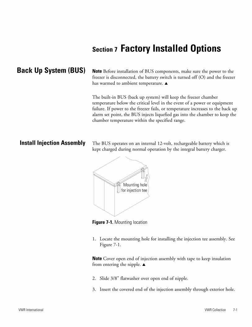
Section 7 Factory Installed Options
Note Before installation of BUS components, make sure the power to thefreezer is disconnected, the battery switch is turned off (O) and the freezerhas warmed to ambient temperature. s
The built-in BUS (back up system) will keep the freezer chambertemperature below the critical level in the event of a power or equipmentfailure. If power to the freezer fails, or temperature increases to the back upalarm set point, the BUS injects liquefied gas into the chamber to keep thechamber temperature within the specified range.
The BUS operates on an internal 12-volt, rechargeable battery which iskept charged during normal operation by the integral battery charger.
1. Locate the mounting hole for installing the injection tee assembly. SeeFigure 7-1.
Note Cover open end of injection assembly with tape to keep insulationfrom entering the nipple. s
2. Slide 3/8” flatwasher over open end of nipple.
3. Insert the covered end of the injection assembly through exterior hole.
VWR Collection 7-1VWR International
Back Up System (BUS)
Install Injection Assembly
Figure 7-1. Mounting location

4. Remove the tape covering the end of the nipple and install the 1/8”NPT brass tee on the open end of the nipple. Place Permagum sealantbetween the brass tee and the interior top.
5. Go to the interior and seal around injection assembly with Permagum.
6. Install the transfer hose connecting one end to the injection assembly,the other end to the solenoid valve. Install the solenoid valve to thesupply source. The solenoid mounting bracket is not required and maybe discarded.
Note When selecting a CO2 supply cylinder, it must be equipped with asiphon tube. s
1. Plug the solenoid/probe connector into the BUS connection. Loop theprobe wire back into the base/side car. Secure the connector with ascrew on the ends of the connector. The connector is keyed.
2. Route the temperature probe through the probe port. The probe portis located in the upper right corner (viewed from the side) of 12.7 and20 cu. ft. models, and in the lower right corner (viewed from the back)of 3.0 and 6.7 cu. ft. models.
7-2 VWR Collection VWR International
Section 7Factory Installed Options
Figure 7-2. Injection Assembly
Install Temperature Probe
probewires
Figure 7-3. Probe and Solenoid Connections
Install Injection Assembly(continued)

VWR Collection 7-3VWR International
Section 7Factory Installed Options
3. Carefully remove the existing Permagum sealant from around theprobe port opening.
4. Open the freezer lid and locate the probe cover on the upper front leftwall. Remove the two Phillips head screws securing the probe cover(see Figure 7-5).
5. Route the BUS probe through the probe port, approximately 12”.Secure the back-up probe to the temperature probe using a small tiewrap (Figure 7-5).
6. Seal around the interior and exterior opening of the probe port withPermagum sealant.
7. Reinstall the probe cover (Figure 7-5).
microboard
battery
bracket
batteryswitch
probeaccessport
Figure 7-4. Probe Access Port
Figure 7-5. Probe location
Install Temperature Probe(continued)

1. Carefully coil the extra probe lead in the compressor compartment,and secure it to the compartment wall with a tie wrap and tie wrapanchor provided. Additional tie wraps and anchors may be used tosecure the probe lead to the exterior back wall of the freezer.
2. Loosen the terminal screws on the solenoid. Slide the spade lugconnectors under the screws and tighten to secure.
3. Connect power to the freezer. Turn the freezer On, with battery switchOff (O).
a. The Solenoid Engaged light on the BUS control panel illuminates(no injection occurs). This light stays on until the unit is belowBUS setpoint.
b. The Low Battery indicator may also illuminate.
4. Turn the battery switch to Standby mode ( ) to charge both batteries.
The following section describes the configuration and operation of theBUS.
Warning When activated, this unit injects liquid nitrogen or carbondioxide. Liquid nitrogen can cause serious freezing (frostbite) if it comes incontact with unprotected skin or eyes. Nitrogen suppresses oxygen levelsand may cause suffocation if area is not well ventilated. Refer to AppendixA for the proper handling of liquid LN2. s
Caution Make sure the pressure relief valve on any LN2 tank is adjusted to30 PSI maximum blow-off. s
Warning Carbon dioxide gas suppresses oxygen levels and may causesuffocation if area is not well ventilated. Refer to “Handling Liquid CO2 inAppendix B of this manual. s
7-4 VWR Collection VWR International
Section 7Factory Installed Options
Connect Probe/SolenoidHarness
BUS Control Panel

Power - indicates the unit has AC power.
Low Battery - battery charge is low. The battery needs replaced orrecharged.
Solenoid Engaged - BUS has opened the solenoid so it can inject gas (CO2
or LN2).
Press-To-Test - Activates the solenoid and injects LN2 or CO2 into thefreezer chamber as long as the button is depressed. The solenoid engagedindicator should light. If the Low Battery indicator lights during the test,replace the BUS battery.
Note The solenoid will not engage if lid is open. s
The optional BUS can be configured for LN2 or CO2 supply. Section 4 -Configuration contains instructions for setting the BUS type.
The optional back up system is designed to inject CO2 or LN2 into thefreezer compartment if the temperature rises above back up system setpoint. To set the BUS set point:
1. Press the Mode key until the Settings indicator lights.
2. Press right arrow until “BACKUP = -XX” displays in message center.
3. Press up or down arrow key until desired BUS set point is displayed.
4. Press Enter to save the setting.
5. Press the Mode key until the Run indicator lights, or press the right orleft arrow to go to the next or previous parameter.
If no control keys are pressed, the freezer will automatically return toRUN mode after 5 minutes.
VWR Collection 7-5VWR International
Section 7Factory Installed Options
Configure Optional BUS(Back Up System)
Figure 7-6. BUS Control Panel
BUS Control Panel(continued)
Set Optional BUS SetPoint

Warning Changing operating temp set point can affect BUS set point.BUS set point self adjusts to maintain a temp of at least 10°C above theoperating temp set point. s
Note The BUS set point cannot be set any colder than the hightemperature alarm set point. (See Section 1 - Setting the HighTemperature Alarm). If the back-up system is installed with CO2, then -65°C is the coldest BUS set point that can be used (if the cabinet set pointis -75°C or colder). s
After the freezer has stabilized and both batteries are fully charged, theBUS can be tested to verify proper operation.
1. Disconnect the AC power to the freezer by turning power switch off.
2. As the freezer warms up, verify the BUS injects at the desiredtemperature. Displayed temperature may vary by a few degrees frominject temperature due to the differences in probe locations.
To disconnect the freezer back-up from the gas supply:
1. Close the supply valve.
2. Depress the test button on the Back-Up System control box to removethe gas from the line.
3. Slowly disconnect the fitting assembly from the supply (in the eventthat any gas remains in the line).
7-6 VWR Collection VWR International
Section 7Factory Installed Options
Set Optional BUS SetPoint (continued)
Disconnect FittingAssembly, Transfer Hose
1 2
3
9-volt battery
Green LED
Program selection and
calibration buttons
1 2
3
Figure 6-7. Recorder Details
Test the BUS
Chart Recorder

The following section describes the set up and operation of the optionalchart recorder.
1. Open the plastic door of the recorder and press button #3 until thepen begins to move outward.
2. Unscrew the knob at the center of the chart and remove the paper.
3. Install the new chart paper, position the paper to the correct time lineand replace the knob.
4. Remove the cap from the felt pen and press button #3.
The chart recorder contains eight temperature ranges and is factory-programmed for the freezer. To change the recorder range:
1. Press and hold button #3 for one second, then let the pen move off thechart paper.
2. Press and hold for five seconds either button #1 or button #2.
3. Release the button and the green LED willbegin to flash. Count the number of flashesto determine the present program setting.
4. To change the program setting, press theleft or right arrows to increase or decreasethe count.
5. When the desired program number isflashing, press button #3 to bring the penarm back onto the chart. Recording willbegin in the new program.
The recorder must be in service for 24 hours before performing thefollowing calibration procedure.
1. Place an accurate thermometer in the chamber next to the recorderprobe.
2. Temperature probes for the recorder are located in the left front cornerof the freezer chamber (Figure 1-4).
3. After about three minutes, compare the thermometer reading with thechart recorder reading.
VWR Collection 7-7VWR International
Section 6Factory Installed Options
Install Chart Paper
Change Program
Program From To
1 -40 30°C
2 0 60°C
3 -100 38°C
4 -5 50°C
5 0 100°C
6 -100 200°C
7 -115 50°C
8 -10 70°C
Calibrate Chart Recorder

4. If an adjustment is necessary, press the #1 button to move the pen tothe left or the #2 to move the pen to the right. The button must beheld about five seconds before the pen begins to move. Release thebutton when the pen position matches the thermometer.
Note The felt-tip pen on the recorder requires periodic replacement.Usually the ink will appear to fade before replacement becomes necessary.Additional pen tips may be purchased from VWR. s
The water-cooled condenser (P/N 195964 [13 cu ft], 195965 [17, 23, 28cu ft], 195967 [12, 17, 20 cu ft chest]) is a factory installed option andrequires a qualified technician at freezer installation. The installationshould include proper adjustment of the regulating valve, which controlsthe discharge pressure. Specifications for this option are displayed in Figure6-8.
7-8 VWR Collection VWR International
Section 6Factory Installed Options
Calibrate Chart Recorder(continued)
Water Source Tower City
Water Pressure Not to exceed 150 psig
Water Temperature Range Not to exceed 29.4C (85F)
Inlet Connection 0.5” compression
Outlet Connection 0.5” compression
Flow Rate Required 3.0 gallons (11.4 liters) per minute 1.0 gallon (3.8 liters) per minute
Drain Required No (return line is required) Yes
Figure 6-8. Water-cooled Condenser Specifications
Water-cooledCondenser

VWR Collection 8-1VWR International
Section 8Warranty Information
VW
R S
CIE
NT
IFIC
PR
OD
UC
TS
FR
EE
ZE
R W
AR
RA
NT
Y -
US
A
The W
arr
anty
Period s
tart
s t
wo w
eeks f
rom
the d
ate
your
equip
ment
is s
hip
ped f
rom
our
facili
ty.
This
allo
ws f
or
ship
pin
g t
ime
so t
he w
arr
anty
will
go into
effect
at
appro
xim
ate
ly t
he s
am
e t
ime y
our
equip
ment
is d
eliv
ere
d.
The w
arr
anty
pro
tection
exte
nds t
o a
ny s
ubsequent
ow
ner
during t
he w
arr
anty
period.
During t
he f
irst
two y
ears
of
the w
arr
anty
period,
com
ponent
part
s p
roven t
o b
e n
on-c
onfo
rmin
g in m
ate
rials
or
work
manship
will
be r
epaired o
r re
pla
ced a
t V
WR
/Therm
o S
cie
ntific’s
expense,
labor
inclu
ded.
The V
WR
Colle
ction U
LT
Fre
ezers
inclu
de
an a
dditio
nal th
ree y
ear
warr
anty
on t
he c
om
pre
ssors
, part
s o
nly
, F.O
.B.
facto
ry.
Insta
llation a
nd c
alib
ration is n
ot
covere
d b
y
this
warr
anty
agre
em
ent. T
he T
echnic
al S
erv
ices D
epart
ment
must
be c
onta
cte
d f
or
warr
anty
dete
rmin
ation a
nd d
irection
prior
to a
ny w
ork
bein
g p
erf
orm
ed.
Expendable
ite
ms,
i.e., g
lass,
filters
, pilo
t lig
hts
, lig
ht
bulb
s a
nd d
oor
gaskets
are
exclu
d-
ed f
rom
this
warr
anty
.
Repla
cem
ent
or
repair o
f com
ponent
part
s o
r equip
ment
under
this
warr
anty
shall
not
exte
nd t
he w
arr
anty
to e
ither
the
equip
ment
or
to t
he c
om
ponent
part
beyond t
he o
rigin
al tw
o y
ear
warr
anty
period.
VW
R a
nd/o
r T
herm
o m
ust
giv
e p
rior
appro
val fo
r th
e r
etu
rn o
f any c
om
ponents
or
equip
ment.
TH
IS W
AR
RA
NT
Y I
S E
XC
LU
SIV
E A
ND
IN
LIE
U O
F A
LL O
TH
ER
WA
RR
AN
TIE
S,
WH
ET
HE
R W
RIT
TE
N,
OR
AL,
OR
IMP
LIE
D.
NO
WA
RR
AN
TIE
S O
F M
ER
CH
AN
TA
BIL
ITY
OR
FIT
NE
SS
FO
R A
PA
RT
ICU
LA
R P
UR
PO
SE
SH
ALL A
PP
LY.
VW
R/T
herm
o s
hall
not
be lia
ble
for
any indirect
or
consequential dam
ages inclu
din
g,
without
limitation,
dam
ages r
ela
ting t
o
lost
pro
fits
or
loss o
f pro
ducts
.
Your
local V
WR
Sale
s O
ffic
e is r
eady t
o h
elp
with c
om
pre
hensiv
e s
ite p
repara
tion info
rmation b
efo
re y
our
equip
ment
arr
ives.
Printe
d instr
uction m
anuals
care
fully
deta
il equip
ment
insta
llation,
opera
tion,
and p
reventive m
ain
tenance.
If e
quip
ment
serv
ice is r
equired,
ple
ase c
all
the T
echnic
al S
erv
ices O
ffic
e a
t 1-8
00-4
38-4
851 (
US
A a
nd C
anada)
or
1-7
40-3
73-4
763.
We're r
eady t
o a
nsw
er
your
questions o
n e
quip
ment
warr
anty
, opera
tion,
main
tenance,
serv
ice,
and s
pecia
l
applic
ations.
Outs
ide t
he U
SA
, conta
ct
your
local dis
trib
uto
r fo
r w
arr
anty
info
rmation.
ISO
9001
REGI
STER
EDR
ev.
7 1
/15

8-2 VWR Collection VWR International
Section 8Warranty Information
VW
R S
CIE
NT
IFIC
PR
OD
UC
TS
FR
EE
ZE
R W
AR
RA
NT
Y -
IN
TE
RN
AT
ION
AL
The W
arr
anty
Period s
tart
s t
wo m
onth
s f
rom
the d
ate
your
equip
ment
is s
hip
ped f
rom
our
facili
ty.
This
allo
ws f
or
ship
pin
g
tim
e s
o t
he w
arr
anty
will
go into
effect
at
appro
xim
ate
ly t
he s
am
e t
ime y
our
equip
ment
is d
eliv
ere
d.
The w
arr
anty
pro
tection
exte
nds t
o a
ny s
ubsequent
ow
ner
during t
he w
arr
anty
period.
During t
he f
irst
two y
ears
of
the w
arr
anty
period,
com
ponent
part
s p
roven t
o b
e n
on-c
onfo
rmin
g in m
ate
rials
or
work
manship
will
be r
epaired o
r re
pla
ced a
t V
WR
/Therm
o S
cie
ntific's
expense,
labor
exclu
ded.
The V
WR
Colle
ction F
reezers
inclu
de a
n
additio
nal th
ree y
ear
warr
anty
on t
he c
om
pre
ssors
, part
s o
nly
, F.O
.B.
facto
ry.
Insta
llation a
nd c
alib
ration is n
ot
covere
d b
y
this
warr
anty
agre
em
ent. T
he T
echnic
al S
erv
ices D
epart
ment
must
be c
onta
cte
d f
or
warr
anty
dete
rmin
ation a
nd d
irection
prior
to a
ny w
ork
bein
g p
erf
orm
ed.
Expendable
ite
ms,
i.e., g
lass,
filters
, pilo
t lig
hts
, lig
ht
bulb
s a
nd d
oor
gaskets
are
exclu
ded
from
this
warr
anty
.
Repla
cem
ent
or
repair o
f com
ponent
part
s o
r equip
ment
under
this
warr
anty
shall
not
exte
nd t
he w
arr
anty
to e
ither
the
equip
ment
or
to t
he c
om
ponent
part
beyond t
he o
rigin
al tw
o y
ear
warr
anty
period.
VW
R a
nd/o
r T
herm
o m
ust
giv
e p
rior
appro
val fo
r th
e r
etu
rn o
f any c
om
ponents
or
equip
ment.
TH
IS W
AR
RA
NT
Y I
S E
XC
LU
SIV
E A
ND
IN
LIE
U O
F A
LL O
TH
ER
WA
RR
AN
TIE
S,
WH
ET
HE
R W
RIT
TE
N,
OR
AL
, O
R
IMP
LIE
D.
NO
WA
RR
AN
TIE
S O
F M
ER
CH
AN
TA
BIL
ITY
OR
FIT
NE
SS
FO
R A
PA
RT
ICU
LA
R P
UR
PO
SE
SH
AL
L A
PP
LY.
VW
R/T
herm
o s
hall
not
be lia
ble
for
any indirect
or
consequential dam
ages inclu
din
g,
without
limitation,
dam
ages r
ela
ting t
o
lost
pro
fits
or
loss o
f pro
ducts
.
Your
local V
WR
Sale
s O
ffic
e is r
eady t
o h
elp
with c
om
pre
hensiv
e s
ite p
repara
tion info
rmation b
efo
re y
our
equip
ment
arr
ives.
Printe
d instr
uction m
anuals
care
fully
deta
il equip
ment
insta
llation,
opera
tion,
and p
reventive m
ain
tenance.
If e
quip
ment
serv
ice is r
equired,
ple
ase c
all
your
local dis
trib
uto
r or
the T
echnic
al S
erv
ices D
epart
ment
at
1-7
40-3
73-4
763
(1-8
00-4
38-4
851 in U
SA
or
Canada).
We're r
eady t
o a
nsw
er
your
questions o
n e
quip
ment
warr
anty
, opera
tion,
main
tenance,
serv
ice,
and s
pecia
l applic
ations.
Outs
ide t
he U
SA
, conta
ct
your
local dis
trib
uto
r fo
r w
arr
anty
info
rmation.
ISO
9001
REGI
STER
EDR
ev.
7 1
/15

VWR Collection A -1VWR InternationalVWR International
Appendix A Handling Liquid Nitrogen
Warning Contact of liquid nitrogen or cold gas with the skin or eyes maycause serious freezing (frostbite) injury. s
Handle liquid nitrogen carefully.
The extremely low temperature can freeze human flesh very rapidly.When spilled on a surface the liquid tends to cover it completely andintimately, cooling a large area. The gas issuing from the liquid is alsoextremely cold. Delicate tissue, such as that of the eyes, can be damagedby an exposure to the cold gas which would be too brief to affect the skinof the hands or face.
Never allow any unprotected part of your body to touch objects cooledby liquid nitrogen.
Such objects may stick fast to the skin and tear the flesh when you attemptto free yourself. Use tongs to withdraw objects immersed in the liquid,and handle the object carefully.
Wear protective clothing.
Protect your eyes with a face shield or safety goggles (safety glasses withoutside shields do not give adequate protection). Always wear gloves whenhandling anything that is, or may have been, in immediate contact withliquid nitrogen. Insulated gloves are recommended, but heavy leathergloves may also be used. The gloves should fit loosely, so that they can bethrown off quickly if liquid should splash into them. When handlingliquid in open containers, it is advisable to wear high-top shoes. Trousers(which should be cuffless if possible) should be worn outside the shoes.

A -2 VWR Collection VWR International
Appendix AHandling Liquid Nitrogen
The safe handling and use of liquid nitrogen in cryogenic refrigerators anddewar flasks is largely a matter of knowing the potential hazards and usingcommon-sense procedures based on that knowledge. There are twoimportant properties of liquid nitrogen that present potential hazards:
1. It is extremely cold. At atmospheric pressure, liquid nitrogen boils at -320°F (-196°C).
2. Very small amounts of liquid vaporize into large amounts of gas. Oneliter of liquid nitrogen becomes 24.6 cu. ft. (700l) of gas.
The safety precautions in this booklet must be followed to avoid potentialinjury or damage which could result from these two characteristics. Donot attempt to handle liquid nitrogen until you read and fully understandthe potential hazards, their consequences, and the related safetyprecautions. Keep this booklet handy for ready reference and review.
Note Because argon is an inert gas whose physical properties are verysimilar to those of nitrogen, precautions and safe practices for the handlingand use of liquid argon are the same as those for liquid nitrogen. s
Use only containers designed for low temperature liquids.
Cryogenic containers are specifically designed and made of materials thatcan withstand the rapid changes and extreme temperature differencesencountered in working with liquid nitrogen. Even these specialcontainers should be filled SLOWLY to minimize the internal stresses thatoccur when any material is cooled. Excessive internal stresses can damagethe container.
Do not cover or plug the entrance opening of any liquid nitrogenrefrigerator or dewar. Do not use any stopper or other device that wouldinterfere with venting of gas.
These cryogenic liquid containers are generally designed to operate withlittle or no internal pressure. Inadequate venting can result in excessive gaspressure which could damage or burst the container. Use only the loose-fitting necktube core supplied or one of the approved accessories forclosing the necktube. Check the unit periodically to be sure that venting isnot restricted by accumulated ice or frost.
Introduction

VWR Collection A -3
Appendix AHandling Liquid Nitrogen
Use proper transfer equipment.
Use a phase separator or special filling funnel to prevent splashing andspilling when transferring liquid nitrogen into or from a dewar orrefrigerator. The top of the funnel should be partly covered to reducesplashing. Use only small, easily-handled dewars for pouring liquid. Forthe larger, heavier containers, use a cryogenic liquid withdrawal device totransfer liquid from one container to another. Be sure to followinstructions supplied with the withdrawal device. When liquid cylindersor other large storage containers are used for filling, follow the instructionssupplied with those units and their accessories.
Do not overfill containers.
Filling above the bottom of the necktube (or specified maximum level) canresult in overflow and spillage of liquid when the necktube core or cover isplaced in the opening.
Never use hollow rods or tubes as dipsticks.
When a warm tube is inserted into liquid nitrogen, liquid will spout fromthe top of the tube due to gasification and rapid expansion of liquid insidethe tube.
Warning Nitrogen gas can cause suffocation without warning! s
Store and use liquid nitrogen only in a well-ventilated place.
As the liquid evaporates, the resulting gas tends to displace the normal airfrom the area. In closed areas, excessive amounts of nitrogen gas reducethe concentration of oxygen and can result in asphyxiation. Becausenitrogen gas is colorless, odorless and tasteless, it cannot be detected by thehuman senses and will be breathed as if it were air. Breathing anatmosphere that contains less than 18% oxygen can cause dizziness andquickly result in unconsciousness and death.
Note The cloudy vapor that appears when liquid nitrogen is exposed tothe air is condensed moisture; not the gas itself. The issuing gas isinvisible. s
Never dispose of liquid nitrogen in confined areas or places where othersmay enter.
Disposal of liquid nitrogen should be performed outdoors in a safe place.Pour the liquid slowly on gravel or bare earth where it can evaporatewithout causing damage. Do not pour the liquid on pavement.
VWR International

B-1 VWR Collection VWR International
Appendix AHandling Liquid CO2
Appendix B Handling Liquid CO2
Warning High concentrations of CO2 gas can cause asphyxiation! OSHAStandards specify that employee exposure to carbon dioxide in any eight-hour shift of a 40-hour work week shall not exceed the eight-hour timeweighted average of 5000 PPM (0.5% CO2). The short term exposurelimit for 15 minutes or less is 30,000 PPM (3% CO2). Carbon dioxidemonitors are recommended for confined areas where concentrations ofcarbon dioxide gas can accumulate. s
Store and use liquid CO2 only in a well-ventilated place.
As the liquid evaporates, the resulting gas tends to displace the normal airfrom the area. In closed areas, excessive amounts of CO2 gas reduce theconcentration of oxygen and can result in asphyxiation. Because CO2 gasis colorless, odorless and tasteless, it cannot be detected by the humansenses and will be breathed as if it were air. Breathing an atmosphere thatcontains less than 18% oxygen can cause dizziness and quickly result inunconsciousness and death.
Note The cloudy vapor that appears when liquid CO2 is exposed to the airis condensed moisture; not the gas itself. The issuing gas is invisible. s
Never dispose of liquid CO2 in confined areas or places where othersmay enter.
Disposal of liquid CO2 should be done outdoors in a safe place. Pour theliquid slowly on gravel or bare earth where it can evaporate withoutcausing damage. Do not pour the liquid on pavement.

VWR Collection C-1VWR International
Appendix AFirst Aid
Appendix C First Aid
If a person seems to become dizzy or loses consciousness while workingwith liquid nitrogen or carbon dioxide, move to a well-ventilated areaimmediately. If breathing has stopped, apply artificial respiration. Ifbreathing is difficult, give oxygen. Call a physician. Keep warm and atrest.
If exposed to liquid or cold gas, restore tissue to normal body temperature(98.6°F) as rapidly as possible, followed by protection of the injured tissuefrom further damage and infection. Remove or loosen clothing that mayconstrict blood circulation to the frozen area. Call a physician. Rapidwarming of the affected part is best achieved by using water at 108°F.Under no circumstance should the water be over 112°F, nor should thefrozen part be rubbed either before or after rewarming. The patientshould neither smoke nor drink alcohol.
D-1 VWR Collection VWR International
Austria VWR International GmbH Graumanngasse 7 1150 Vienna Tel.: +43 1 97 002 0 Fax: +43 1 97 002 600 E-mail: [email protected]
Belgium VWR International bvba Researchpark Haasrode 2020 Geldenaaksebaan 464 3001 Leuven Tel.: 016 385 011 Fax: 016 385 385 E-mail: [email protected]
Czech Republic VWR International s. r. o. Veetee Business Park Pražská 442 CZ - 281 67 St íbrná Skalice Tel.: +420 321 570 321 Fax: +420 321 570 320 E-mail: [email protected]
Denmark VWR - Bie & Berntsen Transformervej 8 2730 Herlev Tel.: 43 86 87 88 Fax: 43 86 87 90 E-mail: [email protected]
Finland VWR International Oy Valimotie 9 00380 Helsinki Tel.: 09 80 45 51 Fax: 09 80 45 52 00 E-mail: [email protected]
France VWR International S.A.S. Le Périgares – Bâtiment B 201, rue Carnot 94126 Fontenay-sous-Bois cedex Tel.: 0 825 02 30 30 (0,15 € TTC/min) Fax: 0 825 02 30 35 (0,15 € TTC/min) E-mail: [email protected]
Germany VWR International GmbH Hilpertstraße 20a D - 64295 Darmstadt Freecall: 0800 702 00 07 Fax: 0180 570 22 22* Email: [email protected] *0,14 €/Min. aus d. dt. Festnetz
Hungary VWR International Kft. Simon László u. 4. 4034 Debrecen Tel.: (52) 521-130 Fax: (52) 470-069 E-mail: [email protected]
Ireland / Northern Ireland VWR International Ltd / VWR International (Northern Ireland) Ltd Orion Business Campus Northwest Business Park Ballycoolin Dublin 15 Tel.: 01 88 22 222 Fax: 01 88 22 333 E-mail: [email protected]
Italy VWR International PBI S.r.l. Via San Giusto 85 20153 Milano (MI) Tel.: 02-3320311/02-487791 Fax: 800 152999/02-40090010 E-mail: [email protected]
The Netherlands VWR International B.V. Postbus 8198 1005 AD Amsterdam Tel.: 020 4808 400 Fax: 020 4808 480 E-mail: [email protected]
Norway VWR International AS Haavard Martinsens vei 30 0978 Oslo Tel.: 02290 Fax: 815 00 940 E-mail: [email protected]
Poland VWR International Sp. z o.o. Limbowa 5 80-175 Gdansk Tel.: 058 32 38 200 do 204 Fax. 058 32 38 205 E-mail: [email protected]
Portugal VWR International - Material de Laboratório, Lda Edifício Neopark Av. Tomás Ribeiro, 43- 3 D 2790-221 Carnaxide Tel.: 21 3600 770 Fax: 21 3600 798/9 E-mail: [email protected]
Spain VWR International Eurolab S.L. C/ Tecnología 5-17 A-7 Llinars Park 08450 - Llinars del Vallès Barcelona Tel.: 902 222 897 Fax: 902 430 657 E-mail: [email protected]
Sweden VWR International AB Fagerstagatan 18a 163 94 Stockholm Tel.: 08 621 34 00 Fax: 08 621 34 66 E-mail: [email protected]
Switzerland VWR International GmbH Lerzenstrasse 16/18 8953 Dietikon Tel.: 044 745 13 13 Fax: 044 745 13 10 E-mail: [email protected]
Turkey Pro Lab Laboratuar Teknolojileri Ltd. ti. a VWR International Company Orta Mah. Cemal Gürsel Caddesi Ördekcioglu I merkezi No.32/1 34896 Pendik - Istanbul Tel.: +90216 598 2900 Fax: +90216 598 2907 Email: [email protected]
UK VWR International Ltd Customer Service Centre Hunter Boulevard - Magna Park Lutterworth Leicestershire LE17 4XN Tel.: 0800 22 33 44 Fax: 01455 55 85 86 E-mail: [email protected]
Australia VWR International, Pty Ltd. Unit 1/31 Archimedes Place Murarrie, Queensland 4172 Tel.: 1300 727 696 Fax: 1300 135 123
China VWR International China Co., Ltd Rm.219, 2100 Dongming Road Pudong New District Shanghai 200123 Tel.:+86-21-5898 6888 Fax:+86-21-5855 8801 E-mail: [email protected]
India VWR Lab Products Private Limited 135/12, Brigade Towers, 2nd Floor Front wing, Brigade Road, Bengaluru, India – 560 025 Tel.: +91-80-41117125/26 (Bengaluru) Tel.: +91-2522-647911/922 (Mumbai) Fax: +91-80-41117120 E-mail: [email protected]
New Zealand Global Science - A VWR Company 241 Bush Road Albany 0632, Auckland Tel.: 0800 734 100 Fax: 0800 999 002 E-mail: [email protected]
Singapore VWR Singapore Pte Ltd 18 Gul Drive Singapore 629468 Tel.: +65 6505 0760 Fax: +65 6264 3780 E-mail: [email protected]

VWR International, Inc.1310 Goshen ParkwayWest Chester, Pennyslvania 19380U.S.A.
Top Related