


Languages
Pages
Legal

© 2011 Cisco and/or its affiliates. All rights reserved. This document is Cisco Public Information. Page 1 of 19
White Paper
Virtual Port-Channel
Quick Start Guide
White Paper
August, 2011
© 2011 Cisco and/or its affiliates. All rights reserved. This document is Cisco Public Information. Page 2 of 19
Contents
Overview ................................................................................................................................................................... 3
vPC Concepts .......................................................................................................................................................... 5
vPC Configuration ................................................................................................................................................... 6
vPC Configuration Example .................................................................................................................................... 8
Verifiying the vPC configuration ............................................................................................................................ 9
vPC Consistency Checks ...................................................................................................................................... 12
vPC Peer-Gateway ................................................................................................................................................. 15
vPC Delay Restore ................................................................................................................................................. 16
vPC Peer-Keepalive Best Practices...................................................................................................................... 17
vPC Configuration limits ....................................................................................................................................... 17
For More Information ............................................................................................................................................. 18
© 2011 Cisco and/or its affiliates. All rights reserved. This document is Cisco Public Information. Page 3 of 19
Overview
A virtual Port-Channel (vPC) allows links that are physically connected to two different Cisco Nexus™ Series devices to appear as a single Port-Channel to a third device. The third device can be a switch, server, or any other networking device capable of etherchanneling. A vPC can provide Layer 2 multipathing, which allows you to create redundancy by increasing bandwidth, enabling multiple parallel paths between nodes and load-balancing traffic where alternative paths exist. After enabling vPC, you need to configure a peer-keepalive link, which sends heartbeat messages between the two vPC peer devices. A vPC domain includes vPC peer devices, the vPC peer keepalive link, the vPC peer link, and all the Port-Channels in the vPC domain connected to the downstream device. You can have only one vPC domain ID on each pair of Cisco Nexus Series switches, and the domain ID needs to match. A vPC provides the following benefits: • Allows a single device to use a Port-Channel across two upstream devices
• Eliminates Spanning Tree Protocol blocked ports
• Provides a loop-free topology
• Uses all available uplink bandwidth
• Provides fast convergence if either the link or a device fails
• Provides link-level resiliency
• Helps ensure high availability
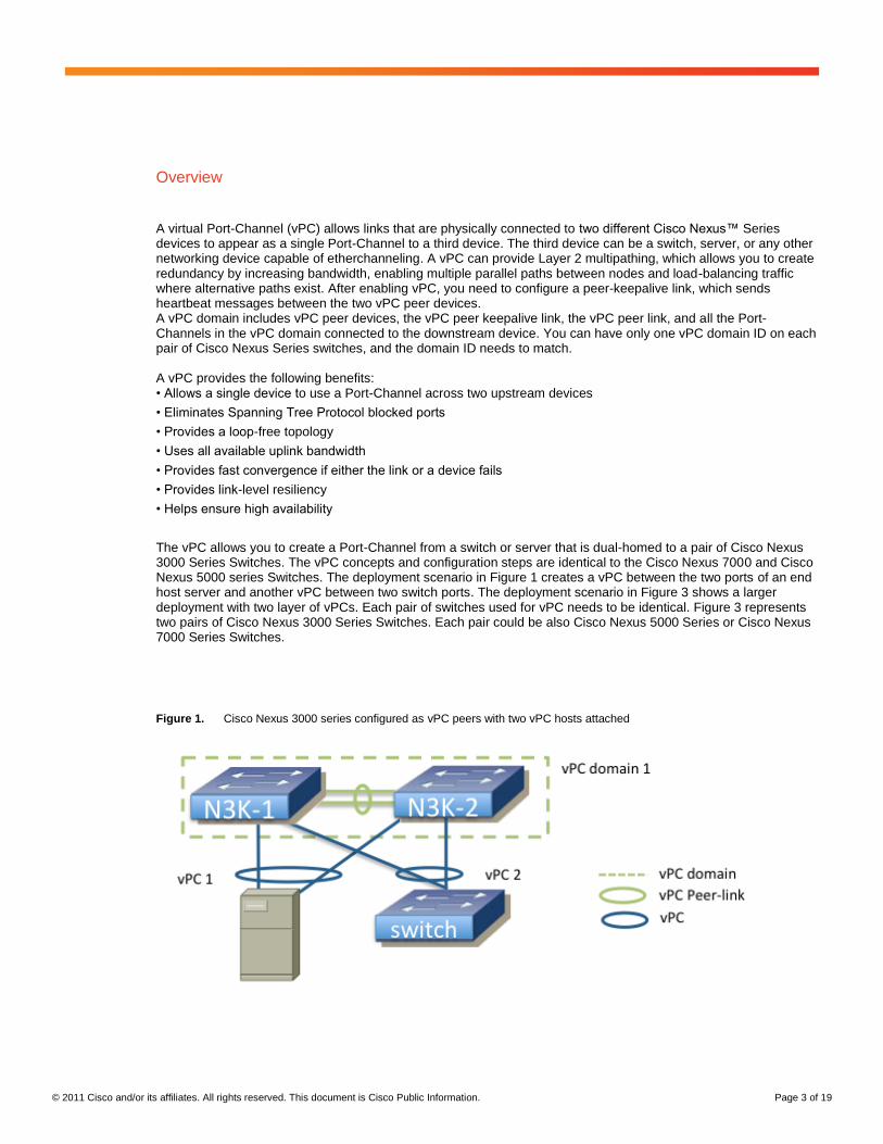
The vPC allows you to create a Port-Channel from a switch or server that is dual-homed to a pair of Cisco Nexus 3000 Series Switches. The vPC concepts and configuration steps are identical to the Cisco Nexus 7000 and Cisco Nexus 5000 series Switches. The deployment scenario in Figure 1 creates a vPC between the two ports of an end host server and another vPC between two switch ports. The deployment scenario in Figure 3 shows a larger deployment with two layer of vPCs. Each pair of switches used for vPC needs to be identical. Figure 3 represents two pairs of Cisco Nexus 3000 Series Switches. Each pair could be also Cisco Nexus 5000 Series or Cisco Nexus 7000 Series Switches.
Figure 1. Cisco Nexus 3000 series configured as vPC peers with two vPC hosts attached

© 2011 Cisco and/or its affiliates. All rights reserved. This document is Cisco Public Information. Page 4 of 19
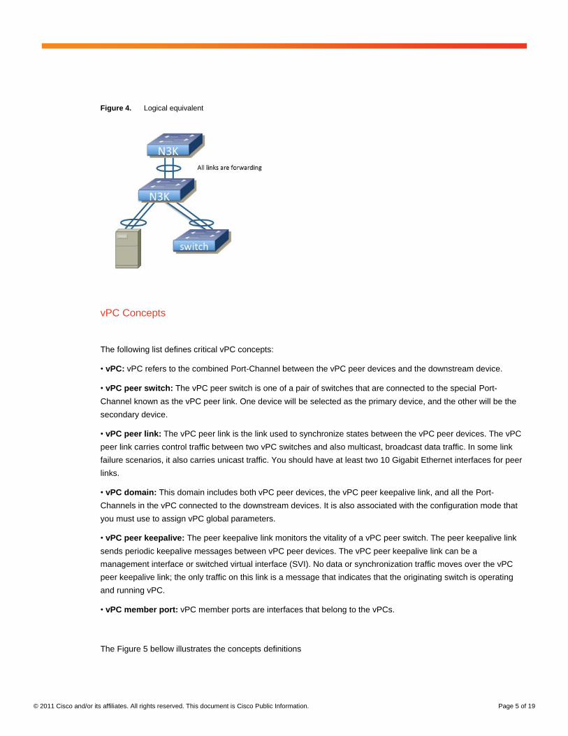
Figure 2. Logical equivalent from the attached switch and server standpoint
Figure 3. Dual Layer vPC with two Cisco Nexus Switches pairs
© 2011 Cisco and/or its affiliates. All rights reserved. This document is Cisco Public Information. Page 5 of 19
Figure 4. Logical equivalent
vPC Concepts
The following list defines critical vPC concepts:
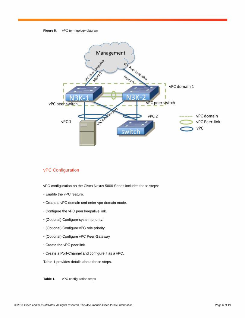
• vPC: vPC refers to the combined Port-Channel between the vPC peer devices and the downstream device.
• vPC peer switch: The vPC peer switch is one of a pair of switches that are connected to the special Port-
Channel known as the vPC peer link. One device will be selected as the primary device, and the other will be the
secondary device.
• vPC peer link: The vPC peer link is the link used to synchronize states between the vPC peer devices. The vPC
peer link carries control traffic between two vPC switches and also multicast, broadcast data traffic. In some link
failure scenarios, it also carries unicast traffic. You should have at least two 10 Gigabit Ethernet interfaces for peer
links.
• vPC domain: This domain includes both vPC peer devices, the vPC peer keepalive link, and all the Port-
Channels in the vPC connected to the downstream devices. It is also associated with the configuration mode that
you must use to assign vPC global parameters.
• vPC peer keepalive: The peer keepalive link monitors the vitality of a vPC peer switch. The peer keepalive link
sends periodic keepalive messages between vPC peer devices. The vPC peer keepalive link can be a
management interface or switched virtual interface (SVI). No data or synchronization traffic moves over the vPC
peer keepalive link; the only traffic on this link is a message that indicates that the originating switch is operating
and running vPC.
• vPC member port: vPC member ports are interfaces that belong to the vPCs.
The Figure 5 bellow illustrates the concepts definitions
© 2011 Cisco and/or its affiliates. All rights reserved. This document is Cisco Public Information. Page 6 of 19
Figure 5. vPC terminology diagram
vPC Configuration
vPC configuration on the Cisco Nexus 5000 Series includes these steps:
• Enable the vPC feature.
• Create a vPC domain and enter vpc-domain mode.
• Configure the vPC peer keepalive link.
• (Optional) Configure system priority.
• (Optional) Configure vPC role priority.
• (Optional) Configure vPC Peer-Gateway
• Create the vPC peer link.
• Create a Port-Channel and configure it as a vPC.
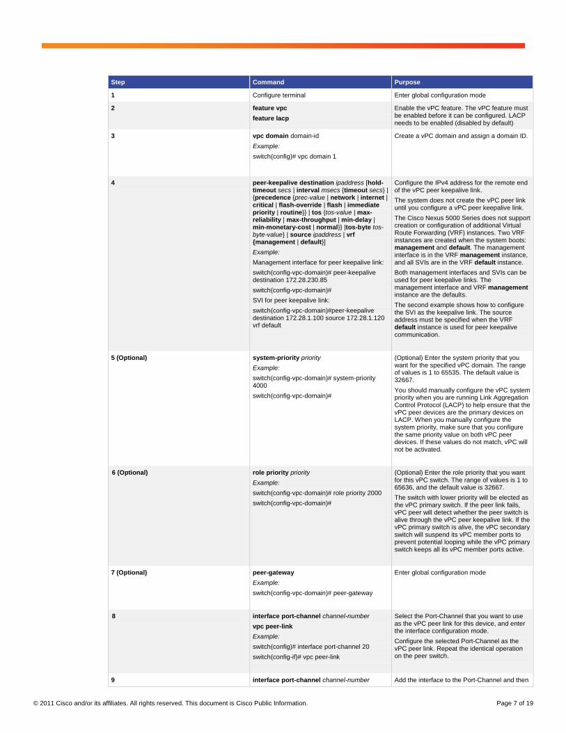
Table 1 provides details about these steps.
Table 1. vPC configuration steps
© 2011 Cisco and/or its affiliates. All rights reserved. This document is Cisco Public Information. Page 7 of 19
Step Command Purpose
1 Configure terminal Enter global configuration mode
2 feature vpc
feature lacp
Enable the vPC feature. The vPC feature must be enabled before it can be configured. LACP needs to be enabled (disabled by default)
3 vpc domain domain-id
Example:
switch(config)# vpc domain 1
Create a vPC domain and assign a domain ID.
4 peer-keepalive destination ipaddress [hold-timeout secs | interval msecs {timeout secs} | {precedence {prec-value | network | internet | critical | flash-override | flash | immediate priority | routine}} | tos {tos-value | max-reliability | max-throughput | min-delay | min-monetary-cost | normal}} |tos-byte tos-byte-value} | source ipaddress | vrf {management | default}]
Example:
Management interface for peer keepalive link:
switch(config-vpc-domain)# peer-keepalive destination 172.28.230.85
switch(config-vpc-domain)#
SVI for peer keepalive link:
switch(config-vpc-domain)#peer-keepalive destination 172.28.1.100 source 172.28.1.120 vrf default
Configure the IPv4 address for the remote end of the vPC peer keepalive link.
The system does not create the vPC peer link until you configure a vPC peer keepalive link.
The Cisco Nexus 5000 Series does not support creation or configuration of additional Virtual Route Forwarding (VRF) instances. Two VRF instances are created when the system boots: management and default. The management interface is in the VRF management instance, and all SVIs are in the VRF default instance.
Both management interfaces and SVIs can be used for peer keepalive links. The management interface and VRF management instance are the defaults.
The second example shows how to configure the SVI as the keepalive link. The source address must be specified when the VRF default instance is used for peer keepalive communication.
5 (Optional) system-priority priority
Example:
switch(config-vpc-domain)# system-priority 4000
switch(config-vpc-domain)#
(Optional) Enter the system priority that you want for the specified vPC domain. The range of values is 1 to 65535. The default value is 32667.
You should manually configure the vPC system priority when you are running Link Aggregation Control Protocol (LACP) to help ensure that the vPC peer devices are the primary devices on LACP. When you manually configure the system priority, make sure that you configure the same priority value on both vPC peer devices. If these values do not match, vPC will not be activated.
6 (Optional) role priority priority
Example:
switch(config-vpc-domain)# role priority 2000
switch(config-vpc-domain)#
(Optional) Enter the role priority that you want for this vPC switch. The range of values is 1 to 65636, and the default value is 32667.
The switch with lower priority will be elected as the vPC primary switch. If the peer link fails, vPC peer will detect whether the peer switch is alive through the vPC peer keepalive link. If the vPC primary switch is alive, the vPC secondary switch will suspend its vPC member ports to prevent potential looping while the vPC primary switch keeps all its vPC member ports active.
7 (Optional) peer-gateway
Example:
switch(config-vpc-domain)# peer-gateway
Enter global configuration mode
8 interface port-channel channel-number
vpc peer-link
Example:
switch(config)# interface port-channel 20
switch(config-if)# vpc peer-link
Select the Port-Channel that you want to use as the vPC peer link for this device, and enter the interface configuration mode.
Configure the selected Port-Channel as the vPC peer link. Repeat the identical operation on the peer switch.
9 interface port-channel channel-number Add the interface to the Port-Channel and then
© 2011 Cisco and/or its affiliates. All rights reserved. This document is Cisco Public Information. Page 8 of 19
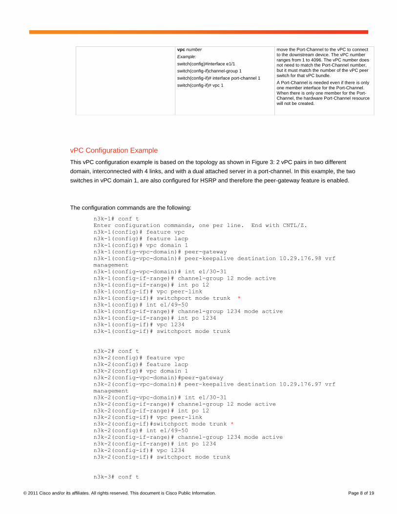
vPC Configuration Example
This vPC configuration example is based on the topology as shown in Figure 3: 2 vPC pairs in two different
domain, interconnected with 4 links, and with a dual attached server in a port-channel. In this example, the two
switches in vPC domain 1, are also configured for HSRP and therefore the peer-gateway feature is enabled.
The configuration commands are the following:
n3k-1# conf t
Enter configuration commands, one per line. End with CNTL/Z.
n3k-1(config)# feature vpc
n3k-1(config)# feature lacp
n3k-1(config)# vpc domain 1
n3k-1(config-vpc-domain)# peer-gateway
n3k-1(config-vpc-domain)# peer-keepalive destination 10.29.176.98 vrf
management
n3k-1(config-vpc-domain)# int e1/30-31
n3k-1(config-if-range)# channel-group 12 mode active
n3k-1(config-if-range)# int po 12
n3k-1(config-if)# vpc peer-link
n3k-1(config-if)# switchport mode trunk *
n3k-1(config)# int e1/49-50
n3k-1(config-if-range)# channel-group 1234 mode active
n3k-1(config-if-range)# int po 1234
n3k-1(config-if)# vpc 1234
n3k-1(config-if)# switchport mode trunk
n3k-2# conf t
n3k-2(config)# feature vpc
n3k-2(config)# feature lacp
n3k-2(config)# vpc domain 1
n3k-2(config-vpc-domain)#peer-gateway
n3k-2(config-vpc-domain)# peer-keepalive destination 10.29.176.97 vrf
management
n3k-2(config-vpc-domain)# int e1/30-31
n3k-2(config-if-range)# channel-group 12 mode active
n3k-2(config-if-range)# int po 12
n3k-2(config-if)# vpc peer-link
n3k-2(config-if)#switchport mode trunk *
n3k-2(config)# int e1/49-50
n3k-2(config-if-range)# channel-group 1234 mode active
n3k-2(config-if-range)# int po 1234
n3k-2(config-if)# vpc 1234
n3k-2(config-if)# switchport mode trunk
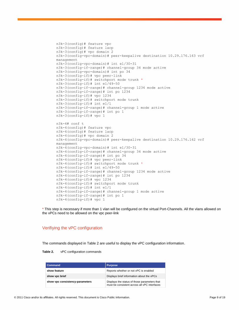
n3k-3# conf t
vpc number
Example:
switch(config)#interface e1/1
switch(config-if)channel-group 1
switch(config-if)# interface port-channel 1
switch(config-if)# vpc 1
move the Port-Channel to the vPC to connect to the downstream device. The vPC number ranges from 1 to 4096. The vPC number does not need to match the Port-Channel number, but it must match the number of the vPC peer switch for that vPC bundle.
A Port-Channel is needed even if there is only one member interface for the Port-Channel. When there is only one member for the Port-Channel, the hardware Port-Channel resource will not be created.
© 2011 Cisco and/or its affiliates. All rights reserved. This document is Cisco Public Information. Page 9 of 19
n3k-3(config)# feature vpc
n3k-3(config)# feature lacp
n3k-3(config)# vpc domain 2
n3k-3(config-vpc-domain)# peer-keepalive destination 10.29.176.163 vrf
management
n3k-3(config-vpc-domain)# int e1/30-31
n3k-3(config-if-range)# channel-group 34 mode active
n3k-3(config-vpc-domain)# int po 34
n3k-3(config-if)# vpc peer-link
n3k-3(config-if)# switchport mode trunk *
n3k-3(config-if)# int e1/49-50
n3k-3(config-if-range)# channel-group 1234 mode active
n3k-3(config-if-range)# int po 1234
n3k-3(config-if)# vpc 1234
n3k-3(config-if)# switchport mode trunk
n3k-3(config-if)# int e1/1
n3k-3(config-if-range)# channel-group 1 mode active
n3k-3(config-if-range)# int po 1
n3k-3(config-if)# vpc 1
n3k-4# conf t
n3k-4(config)# feature vpc
n3k-4(config)# feature lacp
n3k-4(config)# vpc domain 2
n3k-4(config-vpc-domain)# peer-keepalive destination 10.29.176.162 vrf
management
n3k-4(config-vpc-domain)# int e1/30-31
n3k-4(config-if-range)# channel-group 34 mode active
n3k-4(config-if-range)# int po 34
n3k-4(config-if)# vpc peer-link
n3k-4(config-if)# switchport mode trunk *
n3k-4(config-if)# int e1/49-50
n3k-4(config-if-range)# channel-group 1234 mode active
n3k-4(config-if-range)# int po 1234
n3k-4(config-if)# vpc 1234
n3k-4(config-if)# switchport mode trunk
n3k-4(config-if)# int e1/1
n3k-4(config-if-range)# channel-group 1 mode active
n3k-4(config-if-range)# int po 1
n3k-4(config-if)# vpc 1
* This step is necessary if more than 1 vlan will be configured on the virtual Port-Channels. All the vlans allowed on the vPCs need to be allowed on the vpc peer-link
Verifiying the vPC configuration
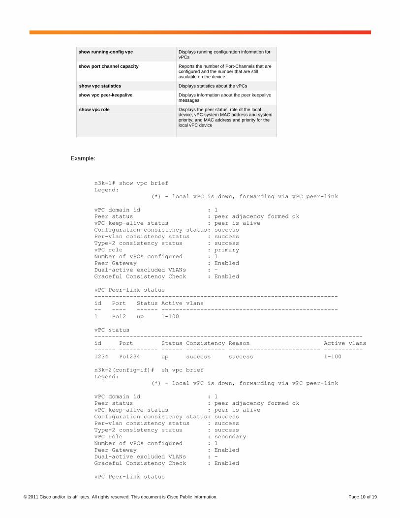
The commands displayed in Table 2 are useful to display the vPC configuration information.
Table 2. vPC configuration commands
Command Purpose
show feature Reports whether or not vPC is enabled
show vpc brief Displays brief information about the vPCs
show vpc consistency-parameters Displays the status of those parameters that must be consistent across all vPC interfaces
© 2011 Cisco and/or its affiliates. All rights reserved. This document is Cisco Public Information. Page 10 of 19
Example:
n3k-1# show vpc brief
Legend:
(*) - local vPC is down, forwarding via vPC peer-link
vPC domain id : 1
Peer status : peer adjacency formed ok
vPC keep-alive status : peer is alive
Configuration consistency status: success
Per-vlan consistency status : success
Type-2 consistency status : success
vPC role : primary
Number of vPCs configured : 1
Peer Gateway : Enabled
Dual-active excluded VLANs : -
Graceful Consistency Check : Enabled
vPC Peer-link status
---------------------------------------------------------------------
id Port Status Active vlans
-- ---- ------ --------------------------------------------------
1 Po12 up 1-100
vPC status
----------------------------------------------------------------------------
id Port Status Consistency Reason Active vlans
------ ----------- ------ ----------- -------------------------- -----------
1234 Po1234 up success success 1-100
n3k-2(config-if)# sh vpc brief
Legend:
(*) - local vPC is down, forwarding via vPC peer-link
vPC domain id : 1
Peer status : peer adjacency formed ok
vPC keep-alive status : peer is alive
Configuration consistency status: success
Per-vlan consistency status : success
Type-2 consistency status : success
vPC role : secondary
Number of vPCs configured : 1
Peer Gateway : Enabled
Dual-active excluded VLANs : -
Graceful Consistency Check : Enabled
vPC Peer-link status
show running-config vpc Displays running configuration information for vPCs
show port channel capacity Reports the number of Port-Channels that are configured and the number that are still available on the device
show vpc statistics Displays statistics about the vPCs
show vpc peer-keepalive Displays information about the peer keepalive messages
show vpc role Displays the peer status, role of the local device, vPC system MAC address and system priority, and MAC address and priority for the local vPC device
© 2011 Cisco and/or its affiliates. All rights reserved. This document is Cisco Public Information. Page 11 of 19
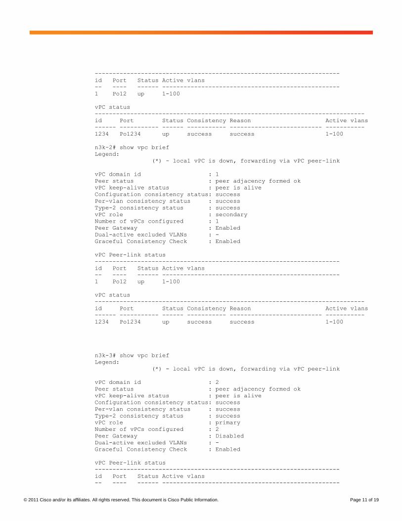
---------------------------------------------------------------------
id Port Status Active vlans
-- ---- ------ --------------------------------------------------
1 Po12 up 1-100
vPC status
----------------------------------------------------------------------------
id Port Status Consistency Reason Active vlans
------ ----------- ------ ----------- -------------------------- -----------
1234 Po1234 up success success 1-100
n3k-2# show vpc brief
Legend:
(*) - local vPC is down, forwarding via vPC peer-link
vPC domain id : 1
Peer status : peer adjacency formed ok
vPC keep-alive status : peer is alive
Configuration consistency status: success
Per-vlan consistency status : success
Type-2 consistency status : success
vPC role : secondary
Number of vPCs configured : 1
Peer Gateway : Enabled
Dual-active excluded VLANs : -
Graceful Consistency Check : Enabled
vPC Peer-link status
---------------------------------------------------------------------
id Port Status Active vlans
-- ---- ------ --------------------------------------------------
1 Po12 up 1-100
vPC status
----------------------------------------------------------------------------
id Port Status Consistency Reason Active vlans
------ ----------- ------ ----------- -------------------------- -----------
1234 Po1234 up success success 1-100
n3k-3# show vpc brief
Legend:
(*) - local vPC is down, forwarding via vPC peer-link
vPC domain id : 2
Peer status : peer adjacency formed ok
vPC keep-alive status : peer is alive
Configuration consistency status: success
Per-vlan consistency status : success
Type-2 consistency status : success
vPC role : primary
Number of vPCs configured : 2
Peer Gateway : Disabled
Dual-active excluded VLANs : -
Graceful Consistency Check : Enabled
vPC Peer-link status
---------------------------------------------------------------------
id Port Status Active vlans
-- ---- ------ --------------------------------------------------
© 2011 Cisco and/or its affiliates. All rights reserved. This document is Cisco Public Information. Page 12 of 19
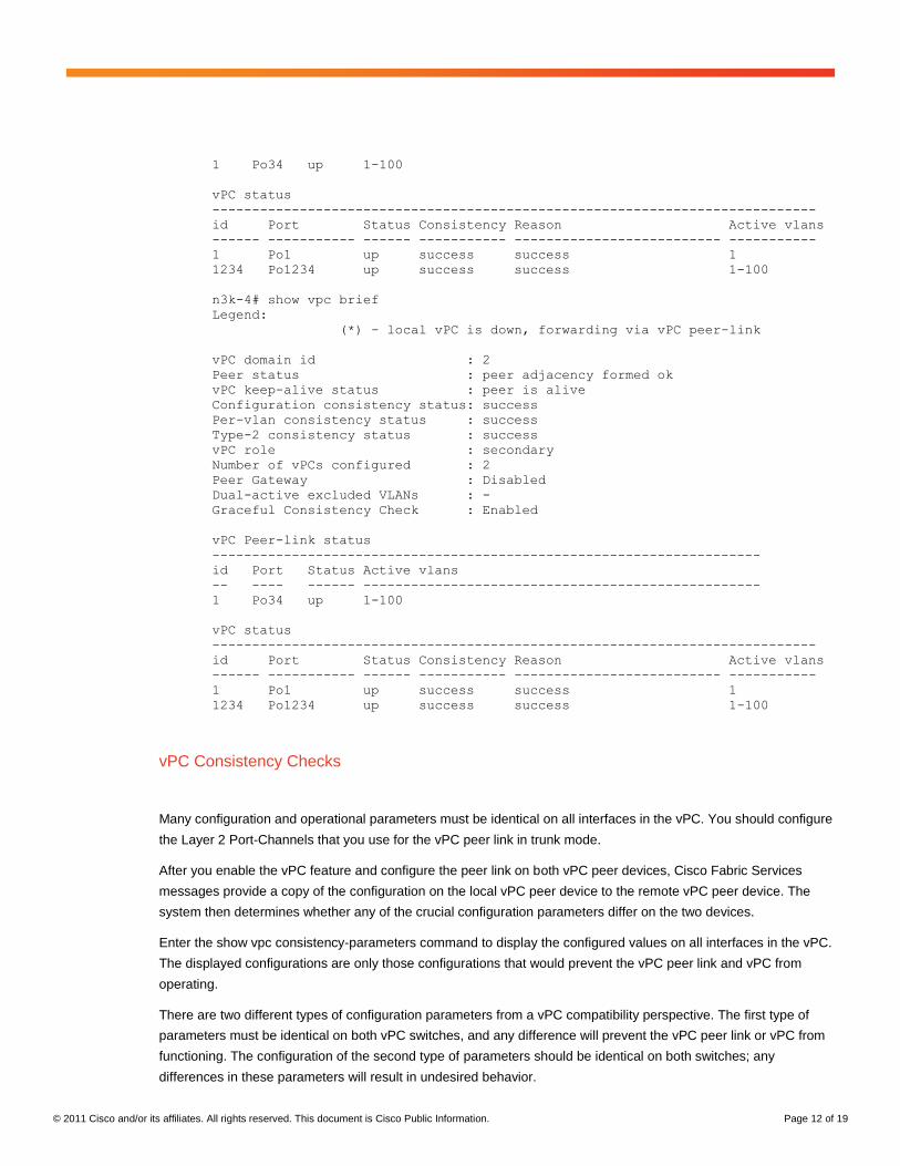
1 Po34 up 1-100
vPC status
----------------------------------------------------------------------------
id Port Status Consistency Reason Active vlans
------ ----------- ------ ----------- -------------------------- -----------
1 Po1 up success success 1
1234 Po1234 up success success 1-100
n3k-4# show vpc brief
Legend:
(*) - local vPC is down, forwarding via vPC peer-link
vPC domain id : 2
Peer status : peer adjacency formed ok
vPC keep-alive status : peer is alive
Configuration consistency status: success
Per-vlan consistency status : success
Type-2 consistency status : success
vPC role : secondary
Number of vPCs configured : 2
Peer Gateway : Disabled
Dual-active excluded VLANs : -
Graceful Consistency Check : Enabled
vPC Peer-link status
---------------------------------------------------------------------
id Port Status Active vlans
-- ---- ------ --------------------------------------------------
1 Po34 up 1-100
vPC status
----------------------------------------------------------------------------
id Port Status Consistency Reason Active vlans
------ ----------- ------ ----------- -------------------------- -----------
1 Po1 up success success 1
1234 Po1234 up success success 1-100
vPC Consistency Checks
Many configuration and operational parameters must be identical on all interfaces in the vPC. You should configure
the Layer 2 Port-Channels that you use for the vPC peer link in trunk mode.
After you enable the vPC feature and configure the peer link on both vPC peer devices, Cisco Fabric Services
messages provide a copy of the configuration on the local vPC peer device to the remote vPC peer device. The
system then determines whether any of the crucial configuration parameters differ on the two devices.
Enter the show vpc consistency-parameters command to display the configured values on all interfaces in the vPC.
The displayed configurations are only those configurations that would prevent the vPC peer link and vPC from
operating.
There are two different types of configuration parameters from a vPC compatibility perspective. The first type of
parameters must be identical on both vPC switches, and any difference will prevent the vPC peer link or vPC from
functioning. The configuration of the second type of parameters should be identical on both switches; any
differences in these parameters will result in undesired behavior.
© 2011 Cisco and/or its affiliates. All rights reserved. This document is Cisco Public Information. Page 13 of 19
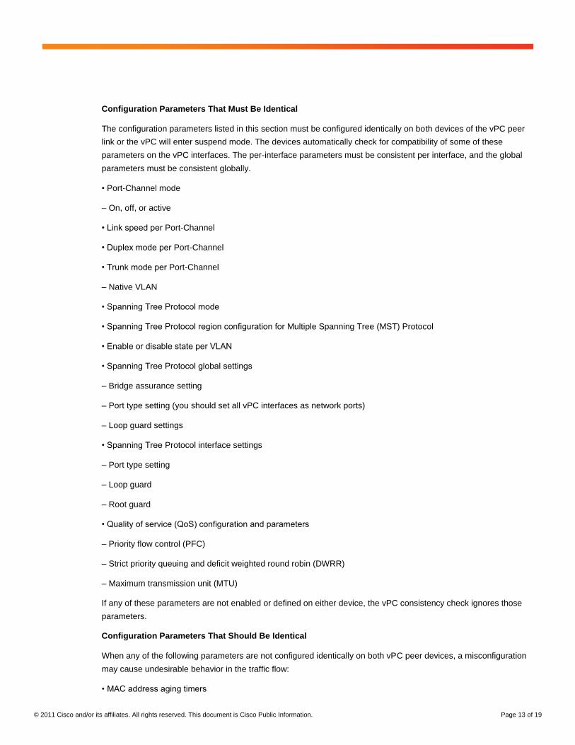
Configuration Parameters That Must Be Identical
The configuration parameters listed in this section must be configured identically on both devices of the vPC peer
link or the vPC will enter suspend mode. The devices automatically check for compatibility of some of these
parameters on the vPC interfaces. The per-interface parameters must be consistent per interface, and the global
parameters must be consistent globally.
• Port-Channel mode
– On, off, or active
• Link speed per Port-Channel
• Duplex mode per Port-Channel
• Trunk mode per Port-Channel
– Native VLAN
• Spanning Tree Protocol mode
• Spanning Tree Protocol region configuration for Multiple Spanning Tree (MST) Protocol
• Enable or disable state per VLAN
• Spanning Tree Protocol global settings
– Bridge assurance setting
– Port type setting (you should set all vPC interfaces as network ports)
– Loop guard settings
• Spanning Tree Protocol interface settings
– Port type setting
– Loop guard
– Root guard
• Quality of service (QoS) configuration and parameters
– Priority flow control (PFC)
– Strict priority queuing and deficit weighted round robin (DWRR)
– Maximum transmission unit (MTU)
If any of these parameters are not enabled or defined on either device, the vPC consistency check ignores those
parameters.
Configuration Parameters That Should Be Identical
When any of the following parameters are not configured identically on both vPC peer devices, a misconfiguration
may cause undesirable behavior in the traffic flow:
• MAC address aging timers
© 2011 Cisco and/or its affiliates. All rights reserved. This document is Cisco Public Information. Page 14 of 19
• Static MAC address entries
• All access control list (ACL) configurations and parameters
• Spanning Tree Protocol interface settings
– Bridge Protocol Data Unit (BPDU) filter
– BPDU guard
– Cost
– Link type
– Priority
– VLANs (Rapid Per-VLAN Spanning Tree Plus [PVST+])
• Internet Group Management Protocol (IGMP) snooping
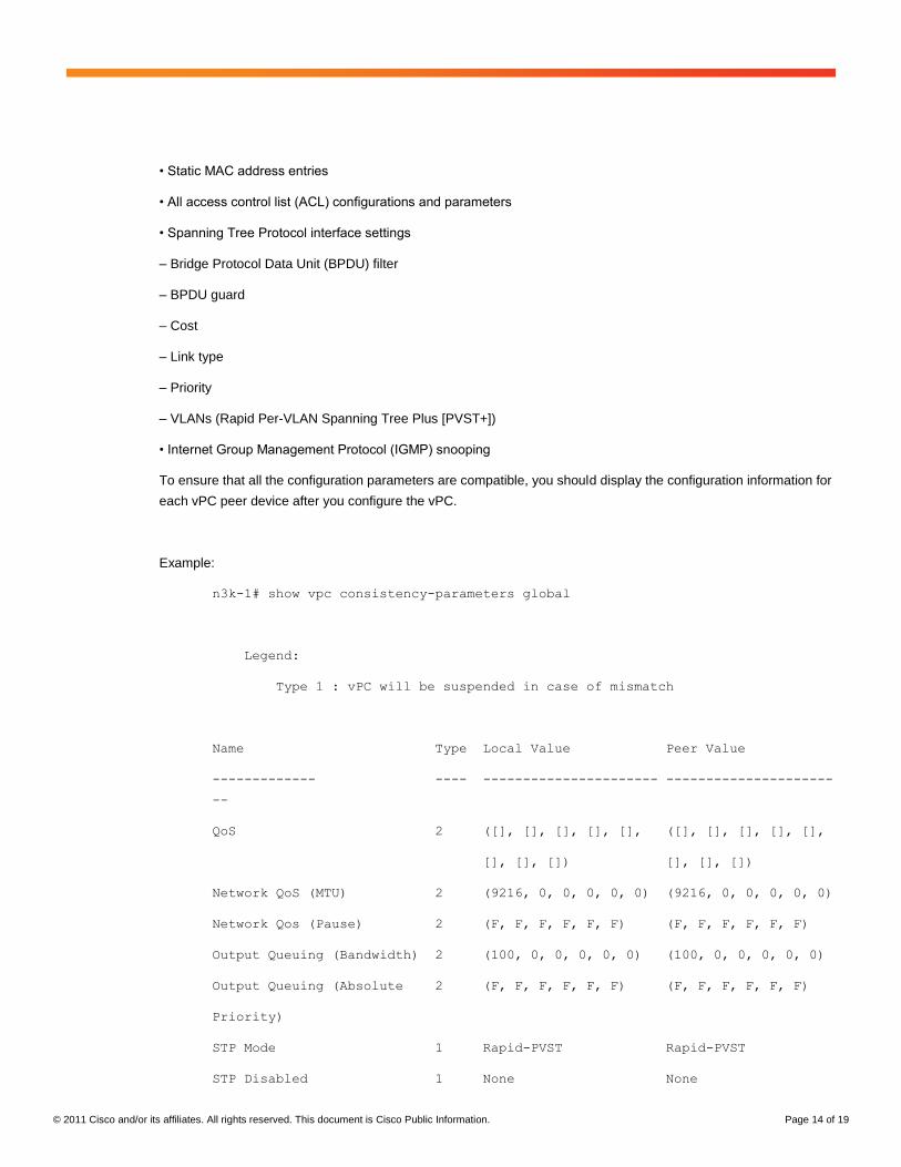
To ensure that all the configuration parameters are compatible, you should display the configuration information for
each vPC peer device after you configure the vPC.
Example:
n3k-1# show vpc consistency-parameters global
Legend:
Type 1 : vPC will be suspended in case of mismatch
Name Type Local Value Peer Value
------------- ---- ---------------------- ---------------------
--
QoS 2 ([], [], [], [], [], ([], [], [], [], [],
[], [], []) [], [], [])
Network QoS (MTU) 2 (9216, 0, 0, 0, 0, 0) (9216, 0, 0, 0, 0, 0)
Network Qos (Pause) 2 (F, F, F, F, F, F) (F, F, F, F, F, F)
Output Queuing (Bandwidth) 2 (100, 0, 0, 0, 0, 0) (100, 0, 0, 0, 0, 0)
Output Queuing (Absolute 2 (F, F, F, F, F, F) (F, F, F, F, F, F)
Priority)
STP Mode 1 Rapid-PVST Rapid-PVST
STP Disabled 1 None None
© 2011 Cisco and/or its affiliates. All rights reserved. This document is Cisco Public Information. Page 15 of 19
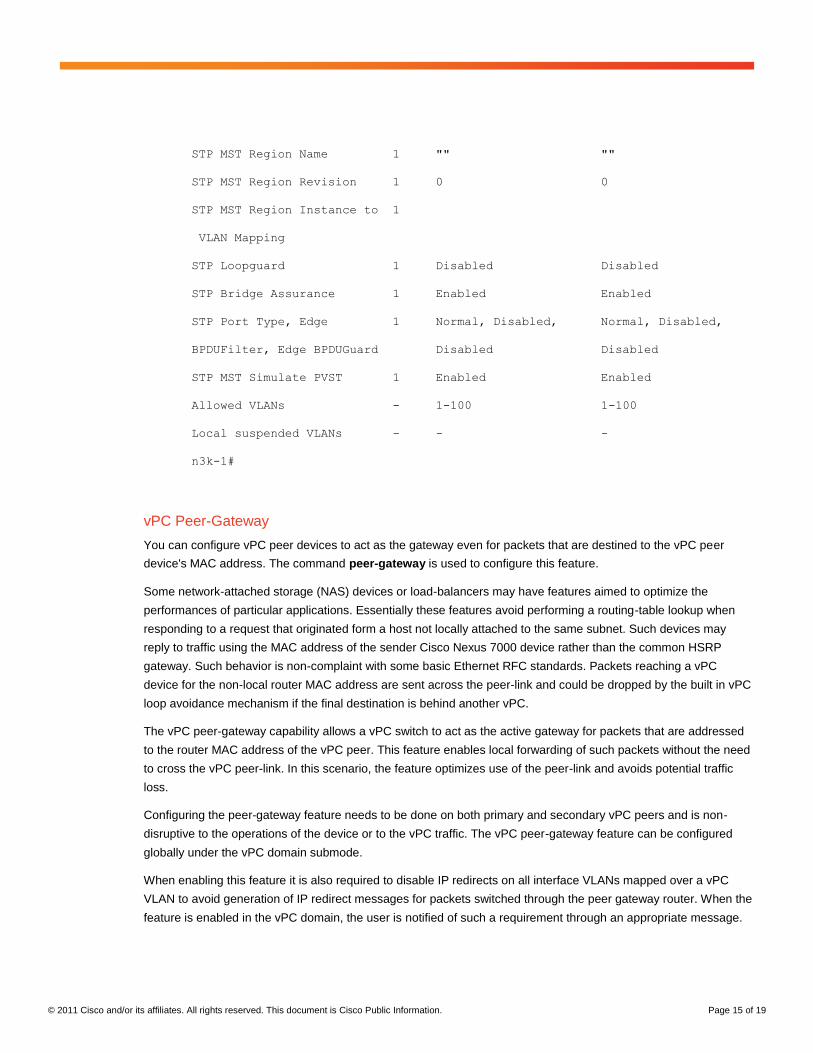
STP MST Region Name 1 "" ""
STP MST Region Revision 1 0 0
STP MST Region Instance to 1
VLAN Mapping
STP Loopguard 1 Disabled Disabled
STP Bridge Assurance 1 Enabled Enabled
STP Port Type, Edge 1 Normal, Disabled, Normal, Disabled,
BPDUFilter, Edge BPDUGuard Disabled Disabled
STP MST Simulate PVST 1 Enabled Enabled
Allowed VLANs - 1-100 1-100
Local suspended VLANs - - -
n3k-1#
vPC Peer-Gateway
You can configure vPC peer devices to act as the gateway even for packets that are destined to the vPC peer
device's MAC address. The command peer-gateway is used to configure this feature.
Some network-attached storage (NAS) devices or load-balancers may have features aimed to optimize the
performances of particular applications. Essentially these features avoid performing a routing-table lookup when
responding to a request that originated form a host not locally attached to the same subnet. Such devices may
reply to traffic using the MAC address of the sender Cisco Nexus 7000 device rather than the common HSRP
gateway. Such behavior is non-complaint with some basic Ethernet RFC standards. Packets reaching a vPC
device for the non-local router MAC address are sent across the peer-link and could be dropped by the built in vPC
loop avoidance mechanism if the final destination is behind another vPC.
The vPC peer-gateway capability allows a vPC switch to act as the active gateway for packets that are addressed
to the router MAC address of the vPC peer. This feature enables local forwarding of such packets without the need
to cross the vPC peer-link. In this scenario, the feature optimizes use of the peer-link and avoids potential traffic
loss.
Configuring the peer-gateway feature needs to be done on both primary and secondary vPC peers and is non-
disruptive to the operations of the device or to the vPC traffic. The vPC peer-gateway feature can be configured
globally under the vPC domain submode.
When enabling this feature it is also required to disable IP redirects on all interface VLANs mapped over a vPC
VLAN to avoid generation of IP redirect messages for packets switched through the peer gateway router. When the
feature is enabled in the vPC domain, the user is notified of such a requirement through an appropriate message.
© 2011 Cisco and/or its affiliates. All rights reserved. This document is Cisco Public Information. Page 16 of 19
Packets arriving at the peer-gateway vPC device will have their TTL decremented, so packets carrying TTL = 1
may be dropped in transit due to TTL expire. This needs to be taken into account when the peer-gateway feature is
enabled and particular network protocols sourcing packets with TTL = 1 operate on a vPC VLAN.
vPC Delay Restore
The First Hop Routing Protocols (FHRP) interoperate with vPCs. The Hot Standby Routing Protocol (HSRP) and
Virtual Router Redundancy Protocol (VRRP) all interoperate with vPCs. We recommend that you dual-attach all
Layer 3 devices to both vPC peer devices.
The primary FHRP device responds to ARP requests, even though the secondary vPC device forwards the data
traffic.
To simplify initial configuration verification and vPC/HSRP troubleshooting, you can configure the primary vPC peer
device with the FHRP active router highest priority.
In addition, you can use the priority command in the if-hsrp configuration mode to configure failover thresholds for
when a group state enabled on a vPC peer link is in standby or in listen state. You can configure lower and upper
thresholds to prevent the interface from going up and down.
VRRP acts similarly to HSRP when running on vPC peer devices. You should configure VRRP the same way that
you configure HSRP. When the primary vPC peer device fails over to the secondary vPC peer device, the FHRP
traffic continues to flow seamlessly. Configure a separate Layer 3 link for routing from the vPC peer devices, rather
than using a VLAN network interface for this purpose. We do not recommend configuring the burnt-in MAC
address option (use-bia) for HSRP or manually configuring virtual MAC addresses for any FHRP protocol in a vPC
environment because these configurations can adversely affect the vPC load balancing. The hsrp use-bia
command is not supported on vPCs. When you are configuring custom MAC addresses, you must configure the
same MAC address on both vPC peer devices.
You can configure a restore timer that will delay the vPC coming back up until after the peer adjacency forms and
the VLAN interfaces are back up. This feature avoids packet drops when the routing tables may not be converged
before the vPC is once again passing traffic. Use the delay restore command under the vpc-domain configuration
to configure this feature.
Note In the event of a data center outage, if the HSRP is enabled before the vPC has successfully come up, traffic
loss can occur. You need to enable an HSRP delay to give the vPC time to stabilize. If you enable both an HSRP
delay and a preemption delay then the Cisco Nexus 3000 Series devices will allow Layer 2 switching only after
both timers expire.
See the Cisco Nexus 3000 Series NX-OS Unicast Routing Configuration Guide for more information on FHRPs
and routing.
© 2011 Cisco and/or its affiliates. All rights reserved. This document is Cisco Public Information. Page 17 of 19
vPC Peer-Keepalive Best Practices
The Cisco NX-OS software uses the peer-keepalive link between the vPC peers to transmit periodic, configurable
keepalive messages. You must have Layer 3 connectivity between the peer devices to transmit these messages.
The system cannot bring up the vPC peer link unless the peer-keepalive link is already up and running.
The Cisco Nexus 3000 Platform switches support VRF lite with the Base or LAN-Enterprise license installed.
This capability allows you to create a VRF and assign a specific interface to the VRF. Without this feature, two
VRFs are created by default: VRF management and VRF default. The mgmt0 interface and all SVI interfaces
reside in VRF management and default.
Ensure that both the source and destination IP addresses used for the peer-keepalive message are unique in your
network and these IP addresses are reachable from the Virtual Routing and Forwarding (VRF) associated with the
vPC peer-keepalive link.
The best practice to use the management VRF with the mgmt0 interface when possible, this is via the out of band
management. Otherwise, for inband management, using the 10GE switch ports, configure a separate VRF instance
and put a Layer 3 port from each vPC peer switch into that VRF for the vPC peer-keepalive link. This will utilize
a dedicated pair of front facing 10 GE ports. Make sure to not use the peer link itself to send vPC peer-keepalive
messages as will create issues. For more information on creating and configuring VPC, see the Cisco Nexus 3000
Series NX-OS Layer 2 Switching Configuration Guide. Finally for more information about configuring the VRFs,
see the Cisco Nexus 3000 Series NX-OS Unicast Routing Configuration Guide.
vPC Configuration limits
The Cisco Nexus 3000 Series Switches are equipped with up to 64 10GE ports. Each port can be part of a vPC.
The maximum number of vPC configurable on the Cisco Nexus 3000 Series Switches is 64. This number is not
achievable since at least two links need to be used for the vPC peer-link. Therefore it can be assumed, that the
limit to the number of vPCs configurable is bound to the physical number of ports present on the switch.
The command show port-channel capacity displays the utilization statistics and free remaining resources.
Example:
n3k-1# show port-channel capacity
Port-channel resources
64 total 2 used 62 free 3% used

© 2011 Cisco and/or its affiliates. All rights reserved. This document is Cisco Public Information. Page 18 of 19
For More Information
http://www.cisco.com/go/nexus3000
http://www.cisco.com/go/nexus5000
http://www.cisco.com/go/nexus7000

© 2011 Cisco and/or its affiliates. All rights reserved. This document is Cisco Public Information. Page 19 of 19
Printed in USA C11-682225-00 08/11
Top Related