


Languages
Pages
Legal


Coupling Computational Fluid Dynamics and Finite Element Analysis to Optimize Heat Transfer in Buildings
Vincent Y. Blouin, PhD
Assistant Professor
School of Architecture
School of Materials Science and Engineering

Outline
• Research goals
• Thermal behavior of buildings
• Method– Finite Element Analysis (FEA)– Computational Fluid Dynamics (CFD)– Coupling FEA and CFD
• Numerical difficulties
• Results
• Conclusion
Research Goals
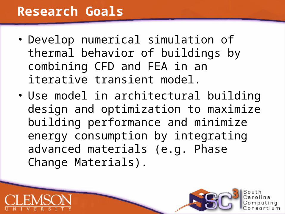
• Develop numerical simulation of thermal behavior of buildings by combining CFD and FEA in an iterative transient model.
• Use model in architectural building design and optimization to maximize building performance and minimize energy consumption by integrating advanced materials (e.g. Phase Change Materials).

Rationale for the Research
• Emergence of new advanced materials in architectural design justifies the need for advanced design methodologies.
• Phase Change Materials (PCMs) have the potential to reduce energy costs by up to 40% if properly designed. Design rules based on numerical simulation must be developed.

Thermal Behavior of Buildings
• Excessive heat gains/losses in buildings are due to:– solar radiation– thermal radiation– indoor and outdoor natural and forced convection– heat generation from lighting, appliances, electronics and users
• To mitigate these effects and maintain a comfortable temperature large amounts of energy are required.
• These effects are time-dependent and control the daily and yearly thermal balance and fluctuations.

Method
• The transient heat transfer problem of the building is solved by Finite Element Analysis (FEA) using ABAQUS.
• The steady-state fluid flow problem of indoor and outdoor fluids is solved by Computational Fluid Dynamics (CFD) using FLUENT.
• These two interrelated problems are coupled in an automated iterative procedure using MATLAB.

Method
FEATransient thermal analysisInput: Heat fluxesOutput: Wall temperatures
CFDSteady state fluid flow analysisInput: Wall temperaturesOutput: Heat fluxes
• The heat fluxes due to convection are computed by CFD based on the wall temperatures, which are computed by FEA based on the heat fluxes.
Method
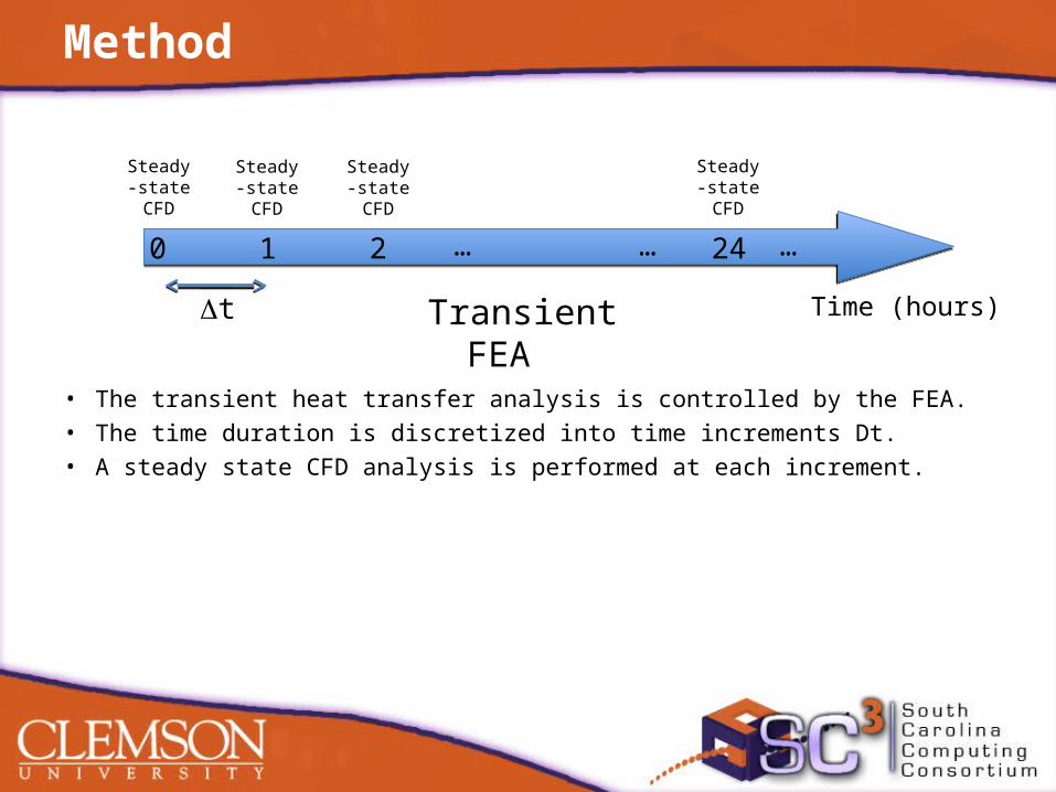
• The transient heat transfer analysis is controlled by the FEA.• The time duration is discretized into time increments Dt.• A steady state CFD analysis is performed at each increment.
Transient FEA Time (hours)
0 1 2 24 …… …
Steady-state CFD
Steady-state CFD
Steady-state CFD
Steady-state CFD
t

CFD Results
• Air flow by natural ventilation through open windows
CFD Results
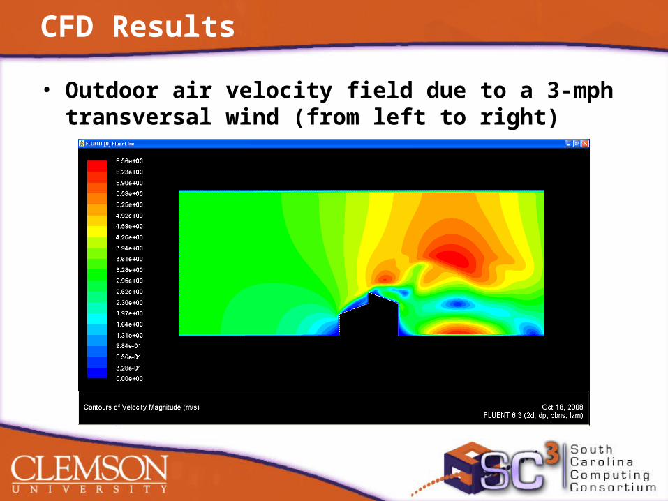
• Outdoor air velocity field due to a 3-mph transversal wind (from left to right)

CFD Results
• Indoor surface heat fluxes due to forced and natural convection
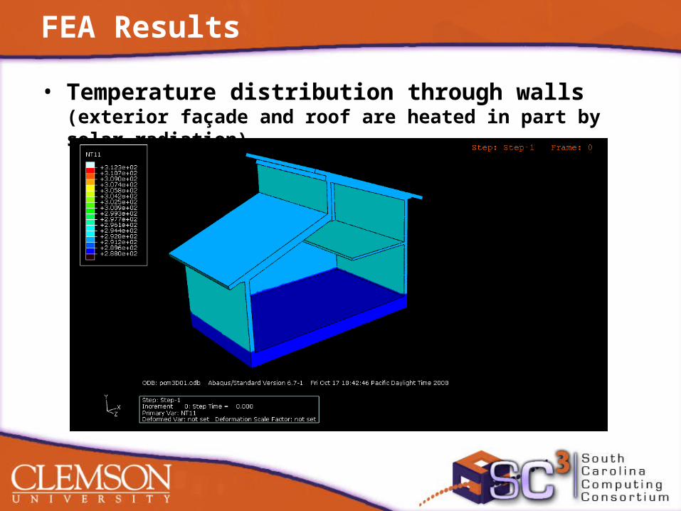
FEA Results
• Temperature distribution through walls (exterior façade and roof are heated in part by solar radiation)
FEA Results
• Outdoor air velocity field due to a 3-mph transversal wind (from left to right)

04/20/23 Vincent Blouin, [email protected] 14

Results
• Temperature fluctuations through building envelope during a 4-day period
Results
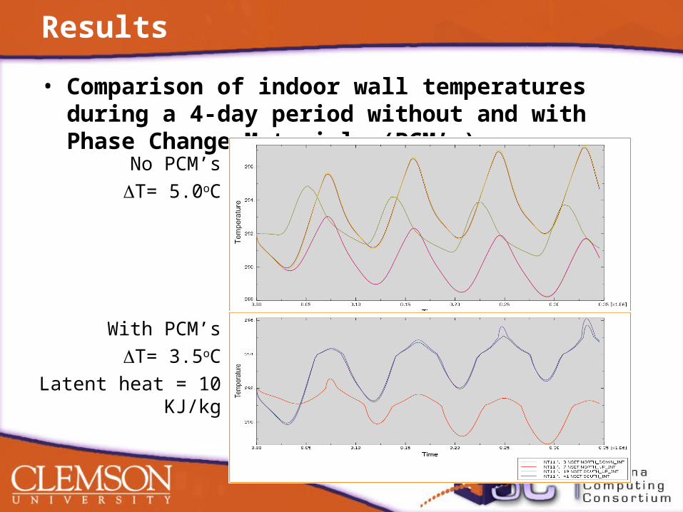
• Comparison of indoor wall temperatures during a 4-day period without and with Phase Change Materials (PCM’s)
No PCM’sT= 5.0oC
With PCM’sT= 3.5oC
Latent heat = 10 KJ/kg

Results
• Comparison of indoor wall temperatures during a 4-day period for two amounts of Phase Change Materials (PCM’s)
Latent heat = 10 KJ/kgT= 3.5oC
Latent heat = 20 KJ/kgT= 2.5oC
Computational Issues
• Design and optimization requires hundreds of simulations.
• Each simulation is an incremental FEA process that may require hundreds of CFD analyses.
• Both FEA and CFD are computationally intense. To achieve the desired accuracy, both models require millions of degrees of freedom.
Conclusion
• Method is computationally challenging• However, it provides versatility and
freedom in terms of geometry and material properties
• Provides a way to simulate thermal behavior of buildings for design and optimization

Future Work
• Validate method with established methods (e.g. enthalpy method)
• Compare with Fluent’s conjugate heat transfer method and other multi-physics software
• Study scalability of the method

Thank you!
Top Related