


Languages
Pages
Legal

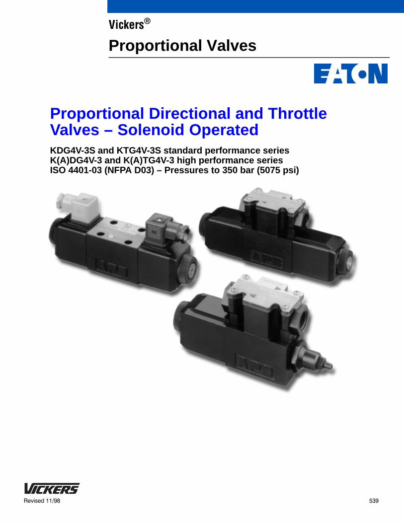
Proportional Directional and Throttle Valves – Solenoid OperatedKDG4V-3S and KTG4V-3S standard performance series K(A)DG4V-3 and K(A)TG4V-3 high performance series ISO 4401-03 (NFPA D03) – Pressures to 350 bar (5075 psi)
Vickers®
Proportional Valves
2
Introduction
KDG and KTG Valves
Vickers KDG and KTG valves arenon-feedback type proportional valves.
The KDG is a proportional directional valvewith two solenoids (C models). Itincorporates control of flow, direction,acceleration, and deceleration in a singlecontrol valve.
The KTG is a proportional throttle valvewith a single solenoid. B models are springcentered with solenoid A removed. Fmodels are spring offset to port A andrespond to an increasing signal byreducing the flow rate. The KTG’s spoolcan be infinitely positioned to achievethrottling (restriction) of the fluid flow.
The primary function of these valves is todirect and meter fluid flow in proportion tocurrent received by the solenoid. This fluidflow controls the velocity, direction, andacceleration or deceleration of a work cylinder or fluid motor.
These valves are designed to fill theperformance gap between conventional
solenoid operated directional valves andservo valves or feedback-type proportionalvalves. They provide control of spoolposition and metered fluid flow inapplications that don’t require the highlevels of accuracy, repeatability, orresponse possible with feedback-typeproportional valves or servos.
Used with Vickers electronic amplifiers,these valves provide an interface betweencontrol system intelligence and hydraulicmuscle. This is a very practical way tocontrol actuator direction and speed whileeliminating shock caused by rapidacceleration and deceleration of machineloads.
In addition to improving machineperformance and life, these proportionalvalves substantially simplify system designby combining direction and flow controlcapabilities in one package that mounts toa standard NFPA/ISO subplate or manifoldinterface.
The valve can also be readily tailored to avast array of applications by specifying the
specific valve configuration which best meetssystem requirements.
The valve is controlled by applying currentto either solenoid A or solenoid B. Thiscurrent produces a force at the solenoidpush pin which, in turn, causes spooltravel. The spool will continue its motionuntil the solenoid force is balanced by thereturn spring force. Therefore, spool travelis proportional to the amount of currentpassing through the solenoid coil.
KADG and KATG ValvesThe above description of KDG and KTGvalves also applies to KADG and KATGvalves, with one exception. “KA” valveshave an integral amplifier, whereas KDGand KTG valves do not.
The control amplifier of KA models ishoused in a sturdy metal enclosure builtdirectly on, and prewired to, the valve.Factory-set adjustments of gain, balancingdeadband and dither ensure highrepeatability valve-to-valve. The onlyelectrical inputs required are powersupply (24V) and a voltage commandsignal of 10V.
Features and Benefits These global products, manufactured to
world-class quality standards, are sold andserviced throughout the world.
KDG4V and KTG4V valves have a lowinstalled cost due to commonality of partswith Vickers DG4V-3(S) solenoidoperated directional valve.
These valves open up expandedapplication opportunities as acost-effective alternative tofeedback-type proportional and servo valves.
Sustained high machine productivity anduptime result from the proven fatigue lifeand endurance of reliable KDG4V andKTG4V valves.
Vickers flexible design approach providesoptimum performance. A wide variety ofmatching electronic amplifiers, valveoptions, and spool ratings allows thesystem designer flexibility in meetingapplication requirements.
All valves are NFPA fatigue rated at 350bar (5075 psi) for improved reliability andperformance.
The fully encapsulated solenoid coils areimpervious to common industrial fluids.Coils can be removed and replacedquickly and easily without breaking intothe hydraulic envelope.
The valves’ standard ISO 4401-03mounting is interchangeable with anyNFPA D03 or CETOP 3 interface.
The engineering resin junction box isNEMA 4 rated for resistance to water andall commonly used industrial fluids.
Advantages of KADG and KATG valveswith integral amplifier:
Factory-sealed adjustments for increasedvalve-to-valve accuracy and simplifiedsystem set-up Valve and amplfierselected, ordered, delivered and installedas a performance-tested package
Installation wiring reduced and simplified
Simplified valve removal and replacement
The use of Viton* O-rings throughoutprovides multi-fluid capability andprevents outside fluids from contactinginternal valve parts.
* Viton is a registered trademark of theDuPont Co.
3
Contents
General Information
Typical Applications, Meter-in and Meter-out, Valve Spool Position, Flow Rates, Recommended Fluids,Pressure Compensation, Accessories, Electrical Signals, Electrical Connectors 4. . . . . . . . . . . . . . . . . . . . . . . . . . . . . . . . .
Cross Section of Typical Valve, Graphical Symbols 5. . . . . . . . . . . . . . . . . . . . . . . . . . . . . . . . . . . . . . . . . . . . . . . . . . . . . . . . . .
System Calculations for Valve Selection 6. . . . . . . . . . . . . . . . . . . . . . . . . . . . . . . . . . . . . . . . . . . . . . . . . . . . . . . . . . . .
KDG4V-3S and KTG4V-3S Standard Performance Valves – 100 bar (1450 psi) tank line rating
Model Code 7. . . . . . . . . . . . . . . . . . . . . . . . . . . . . . . . . . . . . . . . . . . . . . . . . . . . . . . . . . . . . . . . . . . . . . . . . . . . . . . . . . . . . . . .
Application Data
Specifications, Performance, Solenoid Specifications, Step Response TimeSpool, Spool/Spring, Metering, Amplifiers, Drain 8. . . . . . . . . . . . . . . . . . . . . . . . . . . . . . . . . . . . . . . . . . . . . . . . . . . . . . . . . . . . . .
Flow Paths 9. . . . . . . . . . . . . . . . . . . . . . . . . . . . . . . . . . . . . . . . . . . . . . . . . . . . . . . . . . . . . . . . . . . . . . . . . . . . . . . . . . . . . . . . .
Flow Gain Curves 10. . . . . . . . . . . . . . . . . . . . . . . . . . . . . . . . . . . . . . . . . . . . . . . . . . . . . . . . . . . . . . . . . . . . . . . . . . . . . . . . . . .
Power Capacity Envelopes 13. . . . . . . . . . . . . . . . . . . . . . . . . . . . . . . . . . . . . . . . . . . . . . . . . . . . . . . . . . . . . . . . . . . . . . . . . . . .
Frequency Response 14. . . . . . . . . . . . . . . . . . . . . . . . . . . . . . . . . . . . . . . . . . . . . . . . . . . . . . . . . . . . . . . . . . . . . . . . . . . . . . .
Installation Dimensions 15. . . . . . . . . . . . . . . . . . . . . . . . . . . . . . . . . . . . . . . . . . . . . . . . . . . . . . . . . . . . . . . . . . . . . . . . . . . . . . .
EN-427 Feature 16. . . . . . . . . . . . . . . . . . . . . . . . . . . . . . . . . . . . . . . . . . . . . . . . . . . . . . . . . . . . . . . . . . . . . . . . . . . . . . . . . . . .
Electrical Connections 17. . . . . . . . . . . . . . . . . . . . . . . . . . . . . . . . . . . . . . . . . . . . . . . . . . . . . . . . . . . . . . . . . . . . . . . . . . . . . . .
K(A)DG4V-3 and K(A)TG4V-3 High Performance Valves – 210 bar (3000 psi) tank line rating
Model Code 18. . . . . . . . . . . . . . . . . . . . . . . . . . . . . . . . . . . . . . . . . . . . . . . . . . . . . . . . . . . . . . . . . . . . . . . . . . . . . . . . . . . . . . .
Application Data
Specifications, Performance, Solenoid Specifications, Step Input Time, Amplifiers, Drain 19. . . . . . . . . . . . . . . . . . . . . . . . . .
Flow Paths 21. . . . . . . . . . . . . . . . . . . . . . . . . . . . . . . . . . . . . . . . . . . . . . . . . . . . . . . . . . . . . . . . . . . . . . . . . . . . . . . . . . . . . . . .
Flow Gain Curves 22. . . . . . . . . . . . . . . . . . . . . . . . . . . . . . . . . . . . . . . . . . . . . . . . . . . . . . . . . . . . . . . . . . . . . . . . . . . . . . . . . . .
Power Capacity Envelopes 26. . . . . . . . . . . . . . . . . . . . . . . . . . . . . . . . . . . . . . . . . . . . . . . . . . . . . . . . . . . . . . . . . . . . . . . . . . . .
Frequency Response 27. . . . . . . . . . . . . . . . . . . . . . . . . . . . . . . . . . . . . . . . . . . . . . . . . . . . . . . . . . . . . . . . . . . . . . . . . . . . . . . . . . . . . . . . .
Electrical Block Diagram for KADG4V-3 and KATG4V-3 28. . . . . . . . . . . . . . . . . . . . . . . . . . . . . . . . . . . . . . . . . . . . . . . . . . . . . .
Connection Arrangements for KADG4V-3 and and KATG4V-3 29. . . . . . . . . . . . . . . . . . . . . . . . . . . . . . . . . . . . . . . . . . . . . . . . .
Installation Dimensions 30. . . . . . . . . . . . . . . . . . . . . . . . . . . . . . . . . . . . . . . . . . . . . . . . . . . . . . . . . . . . . . . . . . . . . . . . . . . . . . .
Mounting Requirements 32. . . . . . . . . . . . . . . . . . . . . . . . . . . . . . . . . . . . . . . . . . . . . . . . . . . . . . . . . . . . . . . . . . . . . . . . . .
Fluid Cleanliness 33. . . . . . . . . . . . . . . . . . . . . . . . . . . . . . . . . . . . . . . . . . . . . . . . . . . . . . . . . . . . . . . . . . . . . . . . . . . . . . . .
4
General Information
Typical ApplicationsThis type of valve is often used in bothmobile and industrial “line-of-sight”applications where speed and position arecontrolled by an operator. Some examplesare aerial work platforms, entertainmentindustry rides, farm combine controls,material handling equipment, and processcontrols. Any application using aDG4V-3(S) 60-design solenoid operateddirectional valve is a potential applicationfor the KDG4V-3(S) or KTG4V-3(S)
The standard performance KDG4V-3S orKTG4V-3S should be used on mostapplications where a tank line pressurerating of 100 bar (1450 psi) isacceptable. The high performanceKDG4V-3 or KTG4V-3 should be used onapplications where a tank line pressurerating of 210 bar (3000 psi) is required.
Commonly used electrical input devicesinclude joystick controllers, proportionalpush buttons, potentiometers, power plugs,and amplifier cards. Input devices thatoperate on the principle of direct voltagerather than current control will require theappropriate coil type (GP or HA).
Meter-in and Meter-outSystem requirements must be clearlyunderstood and taken into considerationwhen selecting a valve spool. Meter-outspools have the metering notchespositioned between the actuator port andthe tank port, creating a throttle in thehydraulic actuator’s return line. Meter-out isthe most common spool configuration andis typically used in applications with overcenter loads and/or requiring decelerationcontrol.
Meter-in spools have the metering notchespositioned between the pressure port andthe actuator port, creating a throttle in thehydraulic actuator’s inlet line. Meter-inspools are commonly used with hydrostatmodules for pressure compensation inapplications that don’t have an overrunningload as well as in load sensing pumpcircuits.
Spools with both meter-in and meter-outflow characteristics should be specified inapplications where load changes (resistiveto overrunning or vice versa) will occur.They should also be selected whenuncertain system dynamics prevent theselection of specific meter-in or meter-outspool types.
Valve Spool PositionSpring centered and spring offset valveswill be spring positioned unless thesolenoid is energized continuously.
NOTEDue to silting, any sliding spool valveheld shifted under pressure for longperiods may stick and not spring return.It is recommended that such valves becycled periodically to prevent this fromoccurring.
Flow RatesThe rate of flow through a proportionalvalve is dependent on spool position andvalve pressure differential. This is similar toflow through a needle valve. Like a needlevalve, as a proportional valve is opened,the rate of flow increases, and if thepressure differential across the valvechanges (because of load pressurechanges, for example), the flow will vary.Because of this phenomenon, “rated flow”is an arbitrary term, dependent on theabove parameters.
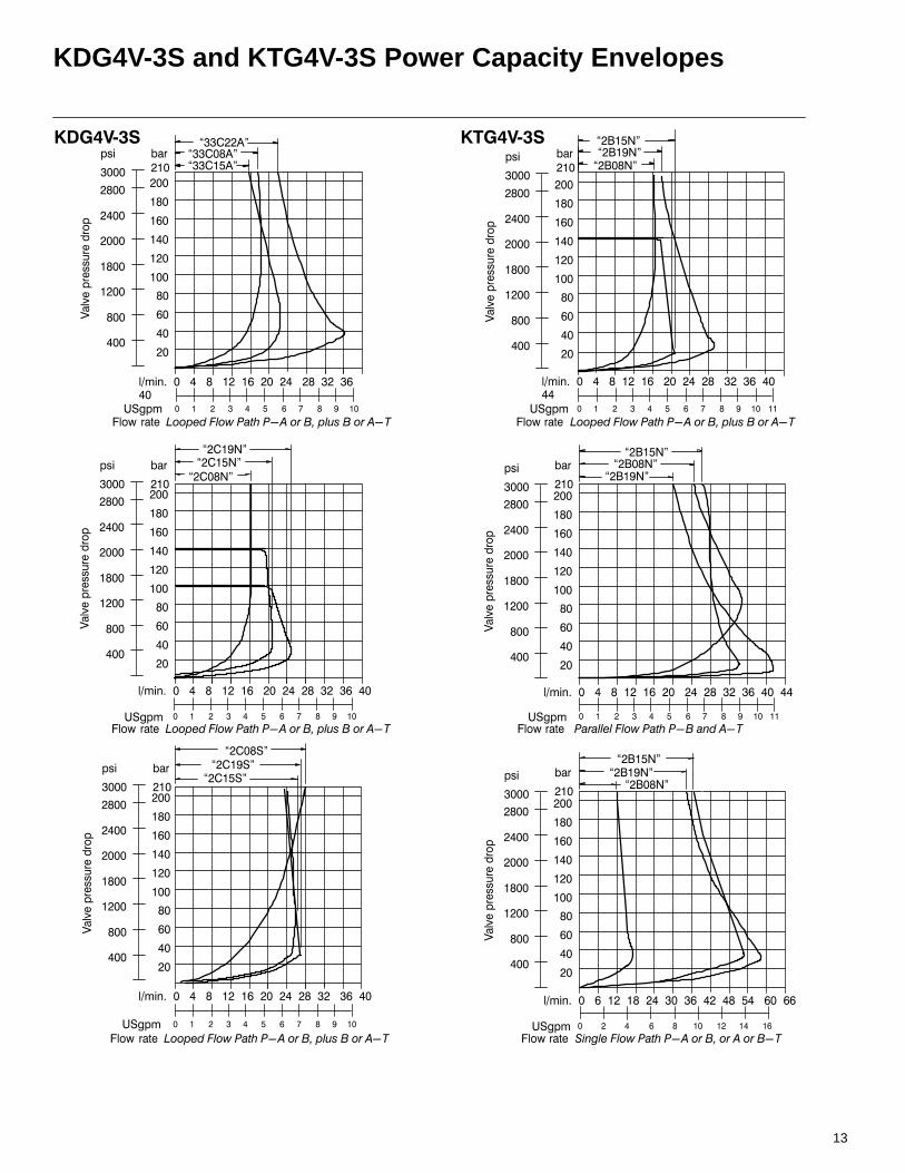
Unlike a needle valve, however,proportional valves exhibit an inherentdegree of load compensation wherebyincreasing valve pressure drop hasprogressively less effect on flow rate (seePower Capacity Envelopes on pages 13and 26). To eliminate the effects ofpressure changes, a hydrostat module canbe installed under the proportional valve toachieve pressure compensation.
Recommended FluidsPetroleum oils are recommended for usewith the KDG4V and KTG4V. Fluorocarbonseals are standard and are suitable for usewith phosphate ester type fluids or blends,water glycol, water-in-oil emulsion fluids,and petroleum oils. Refer to publication694 for fluid and temperaturerecommendations. HWBF (95% water) isnot recommended.
Pressure CompensationFor information on using a SystemStakreducing valve to achieve pressurecompensation control, please contact yourVickers Representative.
AccessoriesSee page 32 for information onmountingsurface, subplate, and bolt kits.
Electrical SignalsIt is important to note that solenoid forceand valve flow are proportional tocurrent—not voltage. Therefore, foroptimum performance, a constant currentelectrical signal should be used. This typeof signal will help compensate for the driftthat would otherwise occur when currentflow causes solenoid temperature andresistance to increase.
Flow is metered directly in proportion to thecommand signal applied to the amplifier.Metering performance is enhanced bymachined metering notches on the valvespool. As the spool travels from itscentered position, these metering notchescreate an increasingly greater orifice area,allowing more fluid to pass.
Electrical ConnectorsKDG4V-3S and KTG4V-3SOn FT (flying lead) models, electricalconnections to the valve are made in thewiring housing, and a ground terminal isprovided. SP1 and SP2 models havespade type terminals on each solenoid.DIN 43650 connectors are also availableby specifying the U coil type. When U1 isspecified, DIN 443650 mating plugs areincluded.
KDG4V-3 and KTG4V-3DIN 43650 connectors are standard.Mating plugs must be ordered separately.

5
KTG4V-3S-2B**N KTG4V-3S-2F**N KTG4V-3S-33B**A
KDG4V-3(S)-2C**N KDG4V-3S-33C**AKDG4V-3(S)-2C**S
b A B
P T
b A B
P T
b A B
P T
b A B
P T
a b A B
P T
a b A B
P T
a
Cross Section of Typical Valve (KTG4V-3S)
Graphical Symbols
KTG4V
KDG4V
Solenoid B Port A Port B
!"#
$% !&#'(((
")*+& ##)%
,#
KDG4V-3-33C**N
b A B
P T
a
KTG4V-3-2B
A B
P T
KTG4V-3-33B
A B
P T
6
System Calculations for Valve Selection
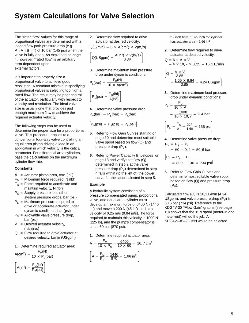
The “rated flow” values for this range ofproportional valves are determined with alooped flow path pressure drop (e.g.P→A→B→T) of 10 bar (145 psi) when thevalve is fully open. As explained on page4, however, “rated flow” is an arbitraryterm dependent upon external factors.
It is important to properly size aproportional valve to achieve goodresolution. A common mistake in specifyingproportional valves is selecting too high arated flow. The result may be poor controlof the actuator, particularly with respect tovelocity and resolution. The ideal valvesize is usually one that provides justenough maximum flow to achieve therequired actuator velocity.
The following steps can be used todetermine the proper size for a proportionalvalve. This procedure applies to aconventional four-way valve controlling anequal area piston driving a load in anapplication in which velocity is the criticalparameter. For differential area cylinders,base the calculations on the maximumcylinder flow rate.
Constants
A = Actuator piston area, cm2 (in2)FM = Maximum force required, N (lbf)FD = Force required to accelerate and
maintain velocity, N (lbf)PS = Supply pressure less other
system pressure drops, bar (psi)PL = Maximum pressure required to
drive or accelerate actuator underdynamic conditions, bar (psi)
PV = Allowable valve pressure drop,bar (psi)
V = Desired actuator velocity,m/s (in/s)
Q = Flow required to drive actuator atdesired velocity, L/min (USgpm)
1. Determine required actuator area:
A(cm2) FM(N)
10 PS(bar)
A(in2) FM(lbf)PS(psi)
2. Determine flow required to driveactuator at desired velocity:
Q(Lmin) 6 A(cm2) V(ms)
Q(USgpm) A(in2) V(ins)
3.85
3. Determine maximum load pressuredrop under dynamic conditions:
PL(bar) FD(N)
10 A(cm2)
PL(psi) FD(lbf)A(in2)
4. Determine valve pressure drop:PV(bar) PS(bar) PL(bar)
PV(psi) PS(psi) PL(psi)
5. Refer to Flow Gain Curves starting onpage 10 and determine most suitablevalve spool based on flow (Q) andpressure drop (PV).
6. Refer to Power Capacity Envelopes onpage 13 and verify that flow (Q)determined in step 2 at the valvepressure drop (PV) determined in step4 falls within (to the left of) the powercurve for the spool selected in step 5.
Example
A hydraulic system consisting of apressure compensated pump, proportionalvalve, and equal area cylinder mustdevelop a maximum force of 6400 N (1440lbf) and move a 200 N (45 lbf) load at avelocity of 0,25 m/s (9.84 in/s).The forcerequired to maintain this velocity is 1000 N(225 lb), and the pump’s compensator isset at 60 bar (870 psi).
1. Determine required actuator area:
A FM
10 PS 6400
10 60 10, 7 cm2
A FM
PS 1440
870 1.66 in2*
* 2 inch bore, 1.375 inch rod cylinder has actuator area = 1.66 in2
2. Determine flow required to driveactuator at desired velocity:
Q 6AV 610, 7 0,25 16,1 Lmin
1.66 9.843.85
4.24 USgpmQ A V
3.85
3. Determine maximum load pressuredrop under dynamic conditions:
PL FD
10 A
PL FD
A 225
1.66 136 psi 1000
10 10, 7 9, 4 bar
4. Determine valve pressure drop:
PV PS PL
PV PS PL
60 9, 4 50, 6 bar
800 136 734 psi]
5. Refer to Flow Gain Curves anddetermine most suitable valve spoolbased on flow (Q) and pressure drop(PV):
Calculated flow (Q) is 16,1 L/min (4.24USgpm), and valve pressure drop (PV) is50,6 bar (734 psi). Reference to theKDG4V-3S “Flow Gain” graphs (see page10) shows that the 15N spool (meter-in andmeter-out) will do the job. AKDG4V–3S–2C15N would be selected.
7
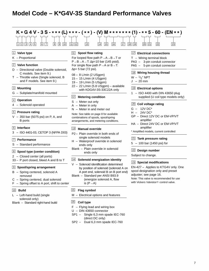
Model Code – K*G4V-3S Standard Performance Valves
Valve type
K – Proportional
Valve function
D – Directional valve (Double solenoid, C models. See item 9.)T – Throttle valve (Single solenoid, B and F models. See item 9.)
Mounting
G – Subplate/manifold mounted
Operation
4 – Solenoid operated
Pressure rating
V – 350 bar (5075 psi) on P, A, and B ports
Interface
3 – ISO 4401-03, CETOP 3 (NFPA D03)
Performance
S – Standard performance
Spool type (center condition)
2 – Closed center (all ports)33 – P port closed, bleed A and B to T
Spool/spring arrangement
B – Spring centered, solenoid A removedC – Spring centered, dual solenoidF – Spring offset to A port, shift to center
3 4 5 876 9 101 2 11 12 13 14 15 16 17 18 19 20
3
4
5
6
7
Spool flow rating
For looped flow path P→A→B→T orP→B→A→T: ∆p=10 bar (145 psid).For single flow path P→A or B→T:∆p= 5 bar (72 psi).
08 – 8 L/min (2 USgpm)15 – 15 L/min (4 USgpm)19 – 19 L/min (5 USgpm)22 – 22 L/min (5.8 USgpm) – available
with KDG4V-3S-33C22A only
Metering condition
S – Meter out onlyA – Meter in onlyN – Meter in and meter out
Manual override
P2– Plain override in both ends of single solenoid models
H – Waterproof override in solenoidends only
Blank – Plain override in solenoid ends only
Solenoid energization identity
V – Solenoid identification determinedby position of solenoid (solenoid A onA port end, solenoid B on B port end)
Blank – Standard per ANSI B93.9 (energize solenoid A, flow is (P→A)
Flag symbol
M – Electrical options and features
Coil type
F – Flying lead and wiring boxU – DIN 43650 connectorSP1 – Single 6,3 mm spade IEC-760
(direct DC only)SP2 – Dual 6,3 mm spade IEC-760
21 22 23
8
9
11
12
13
14
15
1
2
16
Electrical connections
T – Wiring terminal blockPA3 – 3-pin conduit connectorPA5 – 5-pin conduit connector
Wiring housing thread
W – 1/2” NPTJ – 20 mm
Electrical options
1 – ISO 4400 with DIN 43650 plug supplied (U coil type models only)
Coil voltage rating
G – 12V DC*H – 24V DC*GP – Direct 12V DC or EM-VP/VT amplifierHA – Direct 24V DC or EM-VP/VT amplifier* Amplified models, current controlled
Tank pressure rating
5 – 100 bar (1450 psi) for
Design number
Subject to change.
Special modifications
EN-427 – Applies to KTG4V only. Onespool designation only and presetadjuster; see page 16.Note: This valve is recommended for use with Vickers Valvistor control valve.
17
18
19
20
21
22
23
Build
L – Left-hand build (single solenoid only)
Blank – Standard right-hand build
10
Note: See table on page 8 for available combinations of spools, spool/spring arrangements, and metering conditions.
8
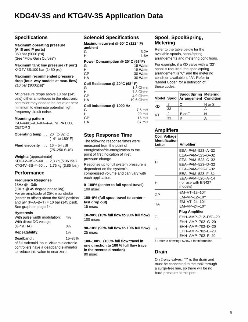
KDG4V-3S and KTG4V-3S Application Data
Maximum current @ 50C (122 F)ambientG 3.2AH 1.6A
Power Consumption @ 20C (68F)G 18 WattsH 18 WattsGP 30 WattsHA 30 Watts
Coil Resistance @ 20C (68 F)G 1.8 OhmsH 7.3 OhmsGP 4.9 OhmsHA 19.6 Ohms
Coil Inductance @ 1000 HzG 7.5 mHH 29 mHGP 16 mHHA 67 mH
The following response times weremeasured from the point of energization/de-energization to the point of first indication of inlet pressure change.
Response up to full system pressure isdependent on the system’s compressed volume and can vary witheach application.
0–100% (center to full spool travel) 100 msec
100–0% (full spool travel to center –fast drop out) 15 msec
10–90% (10% full flow to 90% full flow)100 msec
90–10% (90% full flow to 10% full flow)25 msec
100–100% (100% full flow travel in one direction to 100 % full flow travel in the reverse direction) 80 msec
Step Response Time
Drain
On 2-way valves, “T” is the drain andmust be connected to the tank througha surge-free line, so there will be noback pressure at this port.
Solenoid Specifications
Specifications
Maximum operating pressure(A, B and P ports) 350 bar (5000 psi)(See “Flow Gain Curves”)
Maximum tank line pressure (T port)K*G4V-3S:100 bar (1450 psi)
Maximum recommended pressuredrop (four–way models at max. flow)210 bar (3000psi)*
*At pressure drops above 10 bar (145psid) dither amplitudes in the electroniccontroller may need to be set at or nearminimum to eliminate potential highfrequency circuit noise.
Mounting pattern ISO–4401–AB–03–4–A, NFPA D03,CETOP 3
Operating temp 20 to 82C. . . (–4 to 180F)
Fluid viscosity 16 – 54 cSt. . . (75–250 SUS)
Weights (approximate)KDG4V–3S–*–60 2,3 kg (5.06 lbs.). . KTG4V–3S–*–60 1,75 kg (3.85 lbs.). .
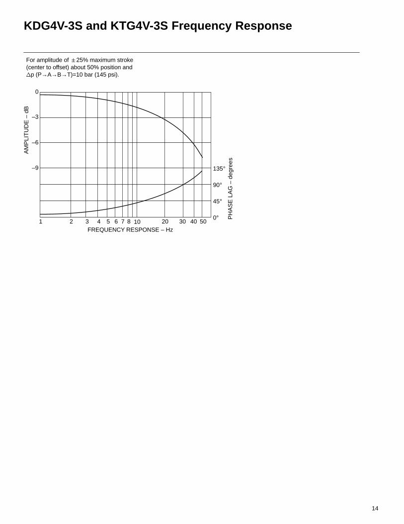
PerformanceFrequency Response18Hz @ –3db(10Hz @ 45 degree phase lag)For an amplitude of 25% max stroke(center to offset) about the 50% positionand P (P–A–B–T) = 10 bar (145 psid).See graph on page 14.
HysteresisWith pulse width modulation: 4%With direct DC voltage (GP & HA): 8%
Repeatability: 1%
Deadband : 15–35%of full solenoid input. Vickers electroniccontrollers have a deadband eliminatorto reduce this value to near zero.
Spool, Spool/Spring,MeteringRefer to the table below for theavailable spools, spool/springarrangements and metering conditions.
For example, if a KD valve with a “33”spool is required, the spool/springarrangement is “C” and the meteringcondition available is “A”. Refer to“Model Code” for a definition of these codes.
Model SpoolSpool/SpringArrangement
MeteringCondition
CC
KD
KT NA
EEA–PAM–523–A–32EEA–PAM–523–B–32EEA–PAM–523–C–32EEA–PAM–523–D–32EEA–PAM–523–E–32EEA–PAM–523–F–32
Amplifiers
Plug Amplifier
EHH–AMP–702–C–20EHH–AMP–702–D–20EHH–AMP–702–E–20EHH–AMP–702–F–20
Amplifier
Coil VoltageIdentificationLetter
GP
HA
H
EEA–PAM–520–A–14(for use with EN427 models)
G EHH–AMP–712–D/G–20
Refer to drawing I-521575 for information.
EM–VT–12–10 EM–VP–12–10EM–VT–24–10 EM–VP–24–10
H
H
B or FB
233233
N or SA
9
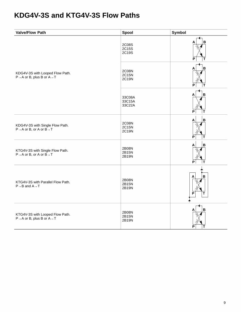
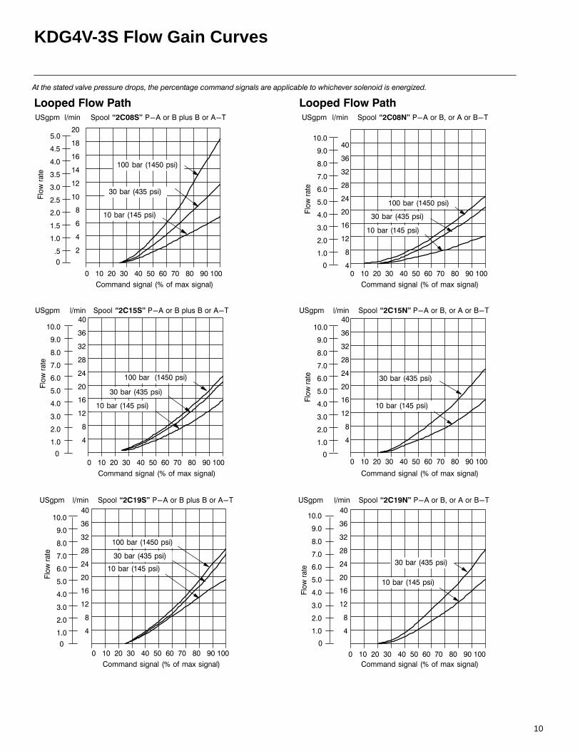
KDG4V-3S and KTG4V-3S Flow Paths
Valve/Flow Path Spool Symbol
2C08S2C15S2C19S
A B
P T
KDG4V-3S with Looped Flow Path.P→A or B, plus B or A→T
2C08N2C15N2C19N
A B
P T
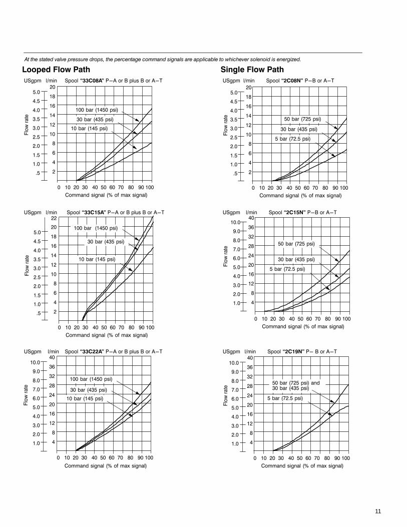
33C08A33C15A33C22A
A B
P T
KDG4V-3S with Single Flow Path.P→A or B, or A or B→T
2C08N2C15N2C19N
A B
P T
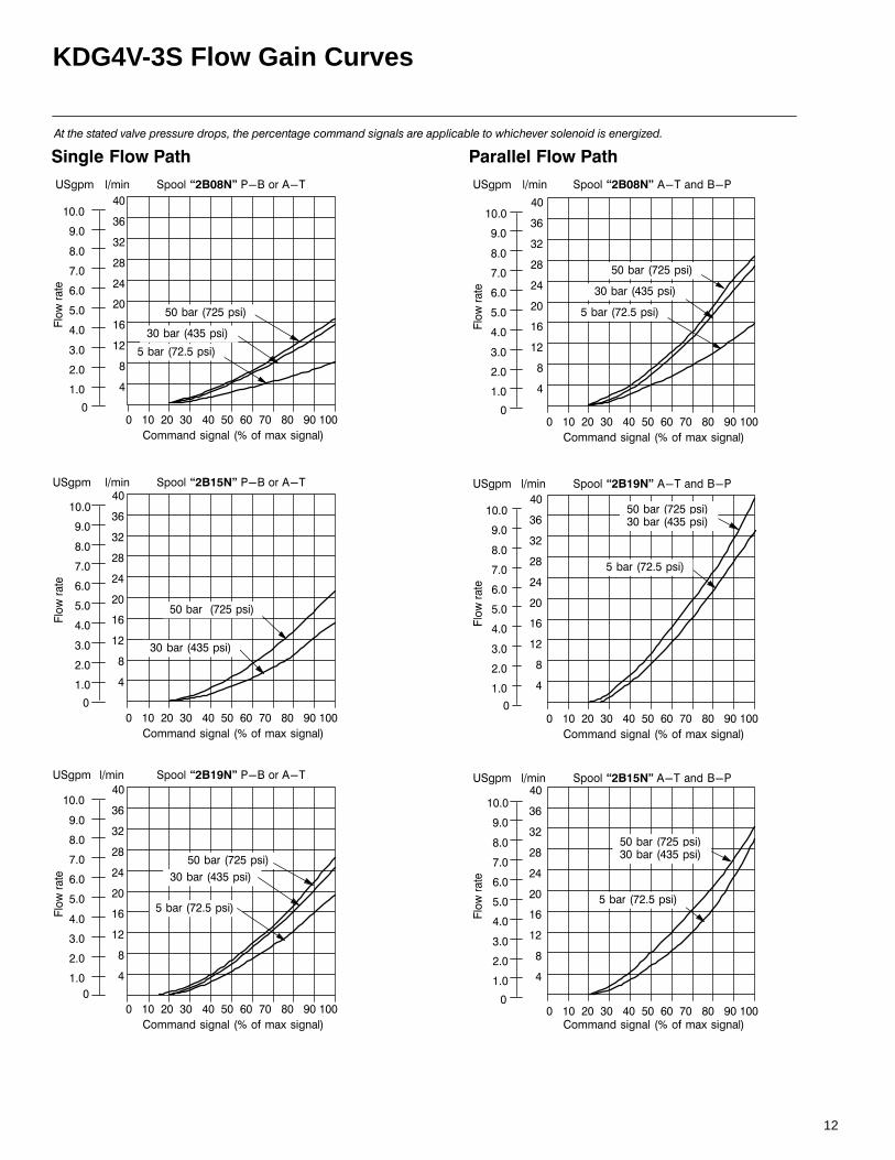
KTG4V-3S with Single Flow Path.P→A or B, or A or B→T
2B08N2B15N2B19N
A B
P T
KTG4V-3S with Parallel Flow Path.P→B and A→T
2B08N2B15N2B19N
A B
P T
KTG4V-3S with Looped Flow Path.P→A or B, plus B or A→T
2B08N2B15N2B19N
A B
P T
10
KDG4V-3S Flow Gain Curves
-.
/
0
0
0-
0.
/
0
-
-.
/
0
0
0-
0.
/
0
-
1
1
1
1
1
1
),!+"&"&+'
.#.
#.
#.
2#.
/#.
#.
-#.
#.
0#.
#.
34567
..0. .-../.2.....
.#.
#.
#.
2#.
/#.
#.
-#.
#.
0#.
#.
-.
/
0
0
0-
0.
/
0
-
34567
..0. .-../.2.....
),!+"&"&+'
..%4-.,7
.%4-,7
8),
8),
),!+"&"&+'
34567
.#.
#.
#.
2#.
/#.
#.
-#.
#.
0#.
#.
-.
/
0
0
0-
0.
/
0
-
..0. .-../.2.....
8),
#.
-#
-#.
#
#.
0#
0#.
#
#.
#
0.
/
-
0
.
/
-
0
),!+"&,9&"+'
34567
..0. .-../.2.....
8),
.#.
#.
#.
2#.
/#.
#.
-#.
#.
0#.
#.
),!+"&,9&"+'
34567
..0. .-../.2.....
8),
..%4-.,7
.%4- ,7
.%4-,7
.%4- ,7
.%4- ,7
.
..
.
.
.#.
#.
#.
2#.
/#.
#.
-#.
#.
0#.
#.
-.
/
0
0
0-
0.
/
0
-
),!+"&,9&"+'
34567
..0. .-../.2.....
8),
.%4- ,7
.%4-,7
..%4-.,7
.
..%4-.,7
.%4- ,7
.%4-,7
.%4- ,7
.%4-,7
.%4-,7
11
0.
/
-
0
.
/
-
0
1
1
1
1
1
1
.#.
#.
#.
2#.
/#.
#.
-#.
#.
0#.
#.
-.
/
0
0
0-
0.
/
0
-
),!+"&,9&"+'
34567
..0. .-../.2.....
#.
-#
-#.
#
#.
0#
0#.
#
#.
#
),!+"&,9&"+'
34567
..0. .-../.2.....
8),
8),
.%4- ,7
.%4-,7
..%4-.,7
.%4- ,7
.%4-,7
..%4-.,7
0.
/
-
0
.
/
-
0
),!+"&,9&"+'
34567
..%4-.,7
.%4-,7
..0. .-../.2.....
.%4- ,7
#.
-#
-#.
#
#.
0#
0#.
#
#.
#
8), 00
.#.
#.
#.
2#.
/#.
#.
-#.
#.
0#.
#.
-.
/
0
0
0-
0.
/
0
-
),!+&"+'
34567
..0. .-../.2.....
8),
#.
-#
-#.
#
#.
0#
0#.
#
#.
#
0.
/
-
0
.
/
-
0
),!+&"+'
34567
..0. .-../.2.....
.%420,7
8),
.#.
#.
#.
2#.
/#.
#.
-#.
#.
0#.
#.
-.
/
0
0
0-
0.
/
0
-
),!+&"+'
34567
..0. .-../.2.....
8),
.%4- ,7
%420#,7
.%420,7 .%4- ,7
%420#,7
.%420,7
.%4- ,7
%420#,7
12
KDG4V-3S Flow Gain Curves
-.
/
0
0
0-
0.
/
0
-
-.
/
0
0
0-
0.
/
0
-
1
1
1
1
1
1
.#.
#.
#.
2#.
/#.
#.
-#.
#.
0#.
#.
.#.
#.
#.
2#.
/#.
#.
-#.
#.
0#.
#.
-.
/
0
0
0-
0.
/
0
-
.#.
#.
#.
2#.
/#.
#.
-#.
#.
0#.
#.
-.
/
0
0
0-
0.
/
0
-
),"+'&+!
34567
..0. .-../.2.....
),"+'&+!
34567
..0. .-../.2.....
),"+'&+!
34567..0. .-../.2.....
8),
8),
8),
),!+&"+'
),!+&"+'
.#.
#.
#.
2#.
/#.
#.
-#.
#.
0#.
#.
-.
/
0
0
0-
0.
/
0
-
34567
..0. .-../.2.....
34567
..0. .-../.2.....
.#.
#.
#.
2#.
/#.
#.
-#.
#.
0#.
#.
-.
/
0
0
0-
0.
/
0
-
34567
..0. .-../.2.....
.#.
#.
#.
2#.
/#.
#.
-#.
#.
0#.
#.
),!+&"+'
8),
8),
8),
.%420,7
%420#,7
.%420,7
.%4- ,7
.%4- ,7
.%420,7
%420#,7
.%4- ,7
.%420,7
%420#,7
.%4- ,7
.%420,7 .%4- ,7
%420#,7
.%420,7 .%4- ,7
%420#,7
.
.
. .
.
.
13
KDG4V-3S and KTG4V-3S Power Capacity Envelopes
0&0&0&.
%
0.
%
0.0..
.
/.
-.
0.
..
.
/.
-.
0.
03
1
03)
03.
3."
:,9,
:,9,
:,9,
:,9,
:,9,
1
#.-0/0.0-0 0 /-.--
0..
.
/.
-.
0.
..
.
/.
-.
0.
0..
0-..
0...
..
0..
..
-..
,
...
#.-0/0.0-0 0 /-.--
0..
.
/.
-.
0.
..
.
/.
-.
0.
%
0.
0..
0-..
0...
..
0..
..
-..
,
...
0..
0-..
0...
..
0..
..
-..
,
...
#.-0/0.0-0 0 /-.
0..
.
/.
-.
0.
..
.
/.
-.
0.
0..
0-..
0...
..
0..
..
-..
,
...
%
0.
1
1
0&0&.
0&
300"
3"
03
#.-0/0.0-0 0 /-.
0..
.
/.
-.
0.
..
.
/.
-.
0.
0..
0-..
0...
..
0..
..
-..
,
...
1
03.)03)
!"#$%
8),
&"#$%
8),
#.-0/0.0-0 0 /-.
%
0.
8),
8),
8),
8),
#./00- . /-0--/.//
:,9,
0..
.
/.
-.
0.
..
.
/.
-.
0.
%
0.
0..
0-..
0...
..
0..
..
-..
,
...
1
0&
0&.0&
. - 0 2 ./
. - 0 2 ./
. - 0 2 ./
. - 0 2 ./
. - 0 2 ./
0 /. -0 ./ -
14
KDG4V-3S and KTG4V-3S Frequency Response
For amplitude of 25% maximum stroke(center to offset) about 50% position andp (P→A→B→T)=10 bar (145 psi).
1 2 3 4 5 6 7 8 10 20 30 40 50
–9
–6
–3
0
135°
90°
45°
0°
AM
PLI
TU
DE
– d
B
PH
AS
E L
AG
– d
egre
esFREQUENCY RESPONSE – Hz

15
KDG4V-3S and KTG4V-3S Installation Dimensions
25,75(1.014)
KDG4V-3S and KTG4V-3S with Junction BoxDimensions in mm (inches) 3rd angle
projection
Two lead wires persolenoid with M3 sizeterminals for customerconnections
23,00(0.906)
26,25(1.033)
“F” and “B” models only
“F” and “B” models with “P2” options
24.60(0.96)
3,0(0.12)
66,75(2.828)
130,07(5.121)
219,63(8.647)
Thread connection“W” – NPT“J” – M20 × 1.5-8H
68,65(2.703)
91,15(3.589)
21,75(0.86)
44,65(1.758)
46,00(1.811)
49,25(1.939)
KDG4V-3S (shown) and KTG4V-3S with DIN ConnectorsDimensions in mm (inches).
Plug connector can be positioned in 90°increments on valve by removing connectorhousing and re-assembling contact holder atdesired orientation inside housing.
Seal
51 (2.01)
27(1.06)
22,5(0.88)∅
M3 thread5,5
(0.22)
1,5(0.06)
30,5(1.20)
26,5 (1.04)
27,5(1.08)
18(0.71)
Coil types: U (shown), SP1, and SP2 (see Model Code)
219,63 (8.647)
78.90(3.10)
51,90(2.044)
33,00(1.299)
Conductor cross-sectional area:0,5 to 1,5 mm2 (0.0008 to 0.0023 in2)
Cable diameter:6 to10 mm (0.24 to 0.40 in)
Water-resistant ManualOverride on SolenoidK*G4V-3S-**(L)-H-(V)M-**-**-60Dimensions in mm (inches)
Use where finger operation is required.(Standard manual overrides cannot beoperated without using small tool.)
This “H” feature is not field-convertiblefrom other models. Please specify withorder.
Spacer
15(0.6)
Overall length of valve withstandard manual overridesManual actuation must be
applied within this diameter.Spacer prevents actuation bylarger device.
Approx. ∅ 20 (0.75)
DIN 43650 plug connector can be ordered separately or included with valve by specifying 1 for Model Code item 19.
Means of connection: screw terminals
Center of mounting hole to center of female connector
16
KTG4V-3S with EN427 Feature
%
0.
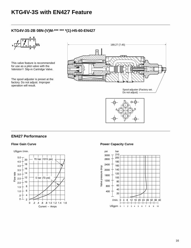
KTG4V-3S-2B 08N-(V)M-*** *** *(1)-H5-60-EN427
1
#.
-#
-#.
#
#.
0#
0#.
#
#.
#
0.
/
-
0
.
/
-
0
39+",
.#0#-#/##.#0#-#/
8), #
2.%4.,7
%42 ,7
.
:,9,
#.-0/0.0-0 0 /-.
0..
.
/.
-.
0.
..
.
/.
-.
0.
0..
0-..
0...
..
0..
..
-..
,
...
8),.0 -/2.
Flow Gain Curve Power Capacity Curve
This valve feature is recommendedfor use as a pilot valve with theValvistor Slip-in Cartridge Valve.
The spool adjuster is preset at thefactory. Do not adjust. Improperoperation will result.
Spool adjuster (Factory set.Do not adjust)
189,27 (7.45)
EN427 Performance
P
A B
T
17
KDG4V-3S and KTG4V-3S Electrical Connections
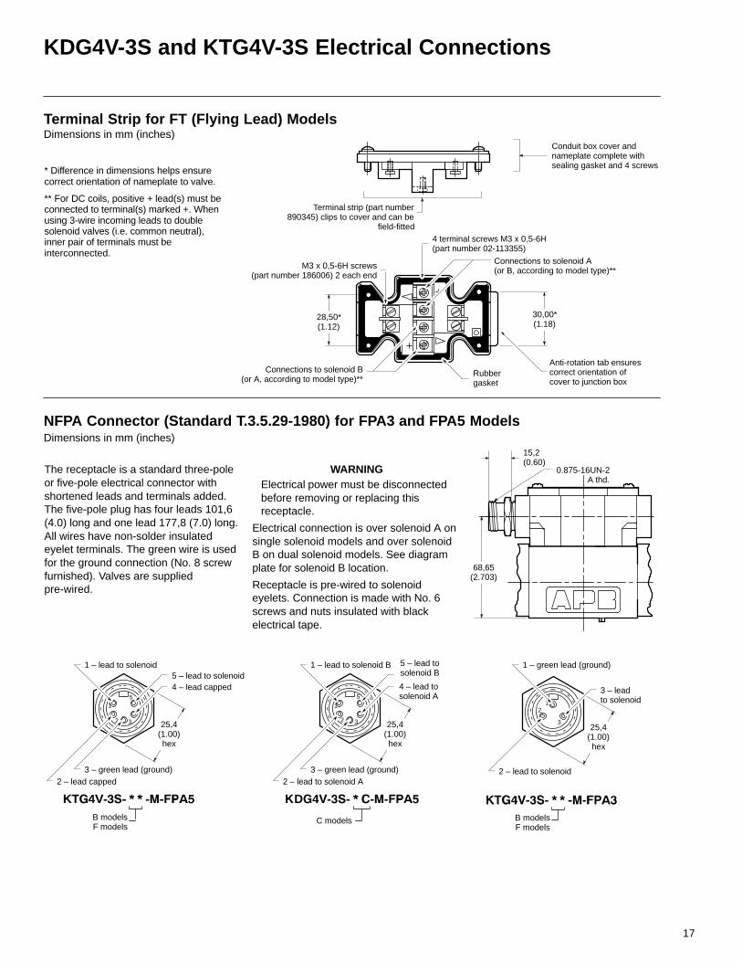
Terminal Strip for FT (Flying Lead) ModelsDimensions in mm (inches)
Terminal strip (part number890345) clips to cover and can be
field-fitted
M3 x 0,5-6H screws(part number 186006) 2 each end
4 terminal screws M3 x 0,5-6H (part number 02-113355)
Connections to solenoid A(or B, according to model type)**
Connections to solenoid B(or A, according to model type)**
Rubbergasket
* Difference in dimensions helps ensurecorrect orientation of nameplate to valve.
** For DC coils, positive + lead(s) must beconnected to terminal(s) marked +. Whenusing 3-wire incoming leads to doublesolenoid valves (i.e. common neutral),inner pair of terminals must beinterconnected.
Conduit box cover andnameplate complete withsealing gasket and 4 screws
Anti-rotation tab ensurescorrect orientation ofcover to junction box
28,50*(1.12)
30,00*(1.18)
41
2 3
5
41
2 3
51
2
325,4(1.00)hex
25,4(1.00)hex
25,4(1.00)hex
NFPA Connector (Standard T.3.5.29-1980) for FPA3 and FPA5 ModelsDimensions in mm (inches)
The receptacle is a standard three-poleor five-pole electrical connector withshortened leads and terminals added.The five-pole plug has four leads 101,6(4.0) long and one lead 177,8 (7.0) long.All wires have non-solder insulatedeyelet terminals. The green wire is usedfor the ground connection (No. 8 screwfurnished). Valves are suppliedpre-wired.
68,65(2.703)
15,2(0.60)
3 – leadto solenoid
1 – green lead (ground)
2 – lead to solenoid
4 – lead capped
1 – lead to solenoid
3 – green lead (ground)
5 – lead to solenoid
2 – lead capped
4 – lead tosolenoid A
1 – lead to solenoid B
3 – green lead (ground)
5 – lead tosolenoid B
2 – lead to solenoid A
0.875-16UN-2A thd.
B modelsF models
B modelsF models
C models
WARNINGElectrical power must be disconnectedbefore removing or replacing thisreceptacle.
Electrical connection is over solenoid A onsingle solenoid models and over solenoidB on dual solenoid models. See diagramplate for solenoid B location.
Receptacle is pre-wired to solenoideyelets. Connection is made with No. 6screws and nuts insulated with blackelectrical tape.
D
18
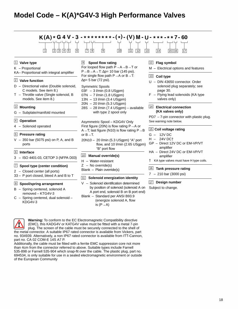
Model Code – K(A)*G4V-3 High Performance Valves
Warning: To conform to the EC Electromagnetic Compatibility directive (EMC), this KADG4V or KATG4V valve must be fitted with a metal 7-pin
plug. The screen of the cable must be securely connected to the shell ofthe metal connector. A suitable IP67 rated connector is available from Vickers, partno. 934939. Alternatively, a non IP67 rated connector is available from ITT-Cannon,part no. CA 02 COM-E 14S A7 P. Additionally, the cable must be fitted with a ferrite EMC suppression core not morethan 4cm from the connector referred to above. Suitable types include Farnell535-898 or Farnell 535-904 which snap-fit over the cable. The plastic plug, part no.694534, is only suitable for use in a sealed electromagnetic environment or outsideof the European Community
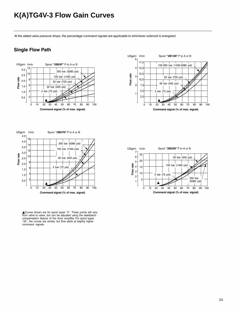
Spool flow ratingFor looped flow path P→A→B→T orP→B→A→T: ∆p= 10 bar (145 psi). For single flow path P→A or B→T: ∆p= 5 bar (72 psi).
Symmetric Spools03F – 3 l/min (0.8 USgpm)07N – 7 l/min (1.8 USgpm)13N – 13 l/min (3.4 USgpm)20N – 20 l/min (5.3 USgpm)28S – 28 l/min (7.4 USgpm) – available
with type 2 spool only
Asymmetric Spool – KDG4V OnlyFirst figure (20N) is flow rating P→A orA→T; last figure (N10) is flow rating P→B or B→T.
20N10 – 20 l/min (5.3 USgpm) “A” port flow, and 10 l/min (2.65 USgpm) “B” port flow
Manual override(s)
H – Water-resistantZ – No override(s) Blank – Plain override(s)
Solenoid energization identity
V – Solenoid identification determinedby position of solenoid (solenoid A onA port end, solenoid B on B port end)
Blank – Standard per ANSI B93.9 (energize solenoid A, flow is (P→A)
Flag symbol
M – Electrical options and features
Coil type
U – DIN 43650 connector. Order solenoid plug separately; see page 30.
F – Flying lead solenoids (KA type valves only)
Electrical connection(KA valves only)
PD7 – 7-pin connector with plastic plug.See warning note below.
Coil voltage rating
G – 12V DCH – 24V DC
GP – Direct 12V DC or EM-VP/VT amplifierHA – Direct 24V DC or EM-VP/VT amplifier KA type valves must have H type coils.
Tank pressure rating
7 – 210 bar (3000 psi)
Design number
Subject to change.
17
Valve type
K – ProportionalKA– Proportional with integral amplifier
Valve function
D – Directional valve (Double solenoid, C models. See item 8.)T – Throttle valve (Single solenoid, B models. See item 8.)
Mounting
G – Subplate/manifold mounted
Operation
4 – Solenoid operated
Pressure rating
V – 350 bar (5075 psi) on P, A, and B ports
Interface
3 – ISO 4401-03, CETOP 3 (NFPA D03)
Spool type (center condition)
2 – Closed center (all ports)33 – P port closed, bleed A and B to T
Spool/spring arrangement
B – Spring centered, solenoid A removed – KTG4V-3C – Spring centered, dual solenoid –
KDG4V-3
3 4 5 6 9 101 2 11 12 13 14 15 16
3
4
5
6
7
8
9
10
13
14
15
1
2
16
7 8
U
11
7
17
12
19
K(A)DG4V-3 and K(A)TG4V-3 Application Data
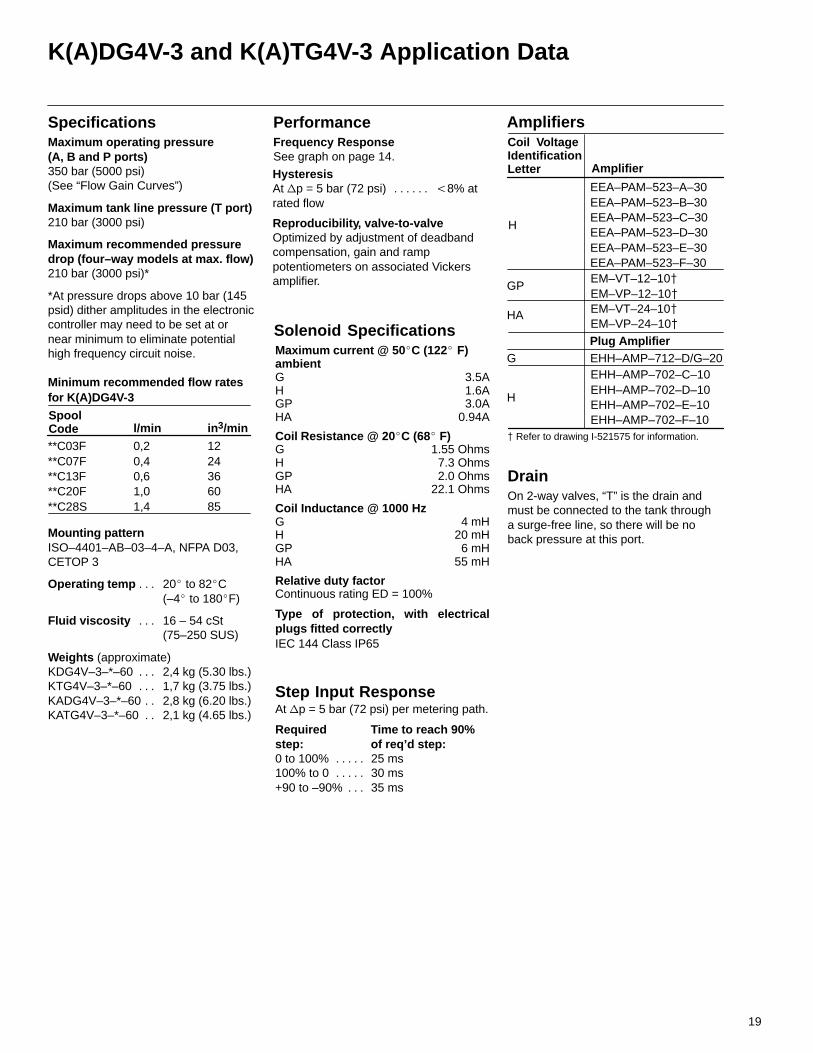
Operating temp 20 to 82C. . . (–4 to 180F)
Fluid viscosity 16 – 54 cSt. . . (75–250 SUS)
Weights (approximate)KDG4V–3–*–60 2,4 kg (5.30 lbs.). . . KTG4V–3–*–60 1,7 kg (3.75 lbs.). . . KADG4V–3–*–60 2,8 kg (6.20 lbs.). . KATG4V–3–*–60 2,1 kg (4.65 lbs.). .
Required Time to reach 90% . . . . . . step: of req’d step:. . . . . . . . . 0 to 100% 25 ms. . . . . 100% to 0 30 ms. . . . . +90 to –90% 35 ms. . .
Step Input Response
DrainOn 2-way valves, “T” is the drain andmust be connected to the tank through a surge-free line, so there will be no back pressure at this port.
Solenoid SpecificationsMaximum current @ 50C (122 F)ambientG 3.5AH 1.6AGP 3.0AHA 0.94A
Coil Resistance @ 20C (68 F)G 1.55 OhmsH 7.3 OhmsGP 2.0 OhmsHA 22.1 Ohms
Coil Inductance @ 1000 HzG 4 mHH 20 mHGP 6 mHHA 55 mH
Relative duty factor Continuous rating ED = 100%
Type of protection, with electricalplugs fitted correctlyIEC 144 Class IP65
Maximum operating pressure(A, B and P ports) 350 bar (5000 psi)(See “Flow Gain Curves”)
Maximum tank line pressure (T port)210 bar (3000 psi)
Maximum recommended pressuredrop (four–way models at max. flow)210 bar (3000 psi)*
*At pressure drops above 10 bar (145psid) dither amplitudes in the electroniccontroller may need to be set at ornear minimum to eliminate potentialhigh frequency circuit noise.
SpecificationsFrequency ResponseSee graph on page 14.
Performance
HysteresisAt p = 5 bar (72 psi) 8% at. . . . . . rated flow
Reproducibility, valve-to-valveOptimized by adjustment of deadbandcompensation, gain and ramppotentiometers on associated Vickersamplifier.
EEA–PAM–523–A–30EEA–PAM–523–B–30EEA–PAM–523–C–30EEA–PAM–523–D–30EEA–PAM–523–E–30EEA–PAM–523–F–30
Amplifiers
Plug Amplifier
EHH–AMP–702–C–10EHH–AMP–702–D–10EHH–AMP–702–E–10EHH–AMP–702–F–10
Amplifier
Coil VoltageIdentificationLetter
GP
HA
H
G EHH–AMP–712–D/G–20
Refer to drawing I-521575 for information.
EM–VT–12–10 EM–VP–12–10EM–VT–24–10 EM–VP–24–10
H
l/minSpoolCode in3/min
coef
**C03F **C07F**C13F **C20F**C28S
0,2 0,40,6 1,01,4
12 2436 6085
Minimum recommended flow ratesfor K(A)DG4V-3
Mounting pattern ISO–4401–AB–03–4–A, NFPA D03,CETOP 3
At p = 5 bar (72 psi) per metering path.
20
KADG4V-3 and KATG4V-3 Application Data
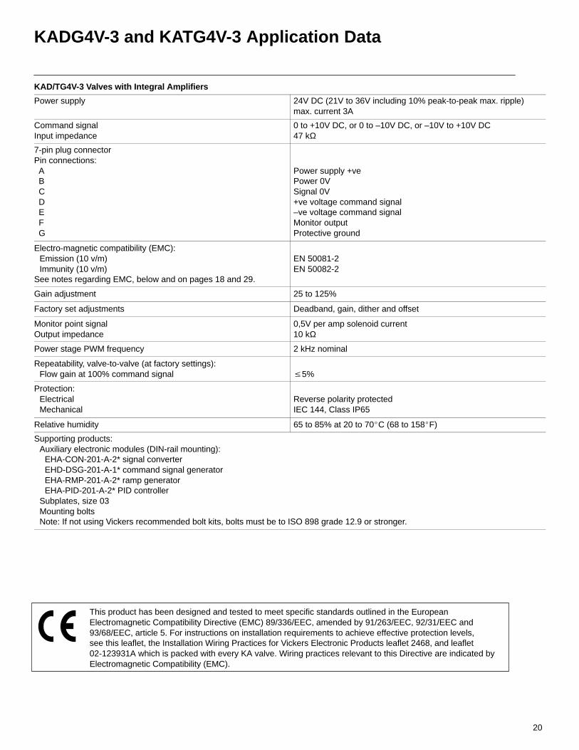
KAD/TG4V-3 Valves with Integral Amplifiers
Power supply 24V DC (21V to 36V including 10% peak-to-peak max. ripple)max. current 3A
Command signalInput impedance
0 to +10V DC, or 0 to –10V DC, or –10V to +10V DC47 kΩ
7-pin plug connectorPin connections: A B C D E F G
Power supply +vePower 0VSignal 0V+ve voltage command signal–ve voltage command signalMonitor outputProtective ground
Electro-magnetic compatibility (EMC):Emission (10 v/m)Immunity (10 v/m)
See notes regarding EMC, below and on pages 18 and 29.
EN 50081-2EN 50082-2
Gain adjustment 25 to 125%
Factory set adjustments Deadband, gain, dither and offset
Monitor point signalOutput impedance
0,5V per amp solenoid current10 kΩ
Power stage PWM frequency 2 kHz nominal
Repeatability, valve-to-valve (at factory settings):Flow gain at 100% command signal 5%
Protection:ElectricalMechanical
Reverse polarity protectedIEC 144, Class IP65
Relative humidity 65 to 85% at 20 to 70C (68 to 158F)
Supporting products:Auxiliary electronic modules (DIN-rail mounting):
EHA-CON-201-A-2* signal converterEHD-DSG-201-A-1* command signal generatorEHA-RMP-201-A-2* ramp generatorEHA-PID-201-A-2* PID controller
Subplates, size 03Mounting bolts Note: If not using Vickers recommended bolt kits, bolts must be to ISO 898 grade 12.9 or stronger.
This product has been designed and tested to meet specific standards outlined in the EuropeanElectromagnetic Compatibility Directive (EMC) 89/336/EEC, amended by 91/263/EEC, 92/31/EEC and93/68/EEC, article 5. For instructions on installation requirements to achieve effective protection levels,see this leaflet, the Installation Wiring Practices for Vickers Electronic Products leaflet 2468, and leaflet02-123931A which is packed with every KA valve. Wiring practices relevant to this Directive are indicated byElectromagnetic Compatibility (EMC).
21
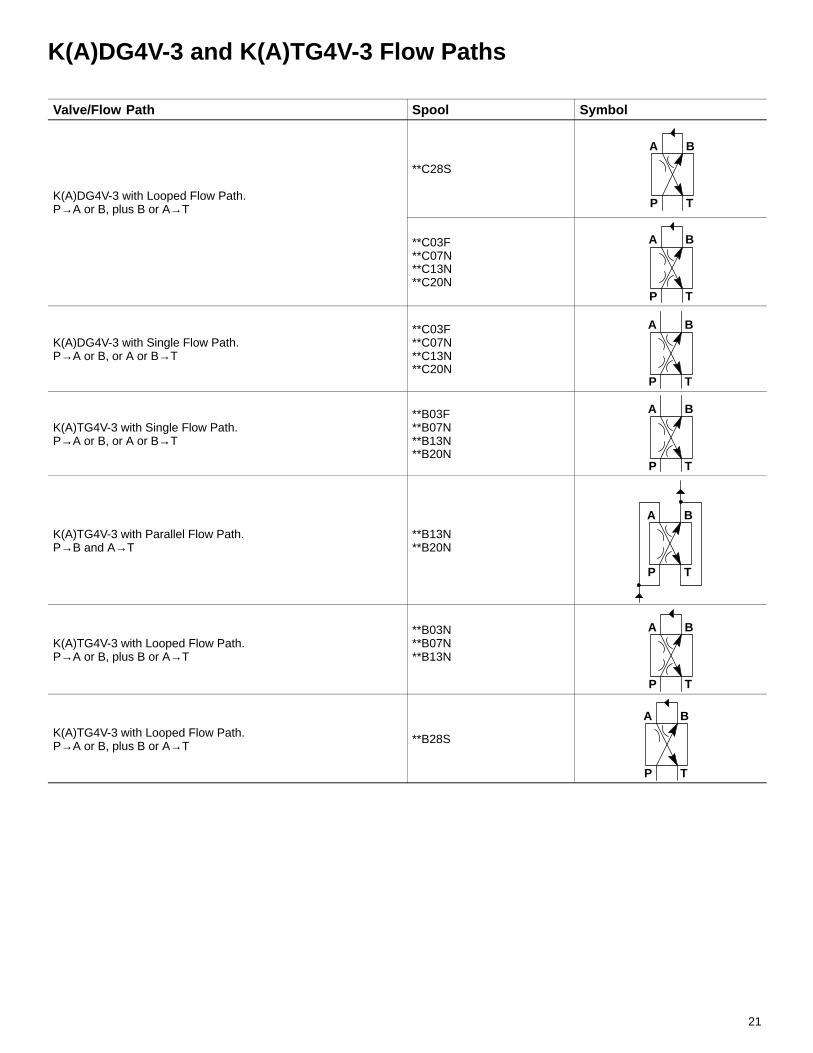
K(A)DG4V-3 and K(A)TG4V-3 Flow Paths
Valve/Flow Path Spool Symbol
K(A)DG4V-3 with Looped Flow Path.P→A or B, plus B or A→T
**C28S
A B
P T
**C03F**C07N**C13N**C20N
A B
P T
K(A)DG4V-3 with Single Flow Path.P→A or B, or A or B→T
**C03F**C07N**C13N**C20N
A B
P T
K(A)TG4V-3 with Single Flow Path.P→A or B, or A or B→T
**B03F**B07N**B13N**B20N
A B
P T
K(A)TG4V-3 with Parallel Flow Path.P→B and A→T
**B13N**B20N
A B
P T
K(A)TG4V-3 with Looped Flow Path.P→A or B, plus B or A→T
**B03N**B07N**B13N
A B
P T
K(A)TG4V-3 with Looped Flow Path.P→A or B, plus B or A→T
**B28S
A B
P T

22
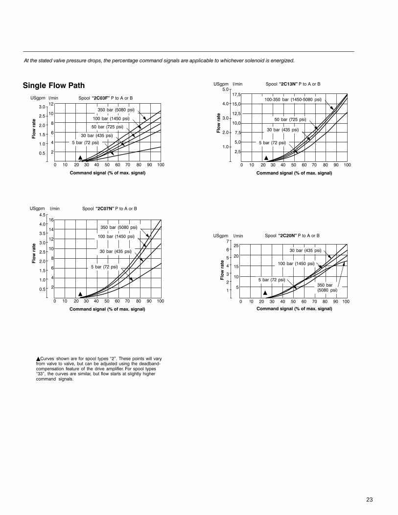
K(A)DG4V-3 Flow Gain Curves
-#.
#
#.
0#
0#.
#
#.
.#
-
0
.
/
-
0
8),
-#
-#.
#
#.
0#
0#.
#
#.
.#
2
.
0
..
2
.
0
.. 0. . -. . /. 2. . . ..
''()*+',-(.
.. 0. . -. . /. 2. . . ..
''()*+',-(.
8),
8),
0#.
#
#.
.#
2
/
-
0
.. 0. . -. . /. 2. . . ..
''()*+',-(.
0#
), !"&,9&"'
), /!"&,9&"'
), !"&,9&"'
.% 4..,7
..% 4-.,7
.%420,7
.%4- ,7
.%4-,7
.% 4..,7
..% 4-.,7
.%4- ,7
.%4-,7
..; . % 4-.;.. ,7
.%4- ,7
.%4-,7
.
2
/
-
0
/
-
0
-.
.
0
0.
.
0
0.
.
.%4- ,7
.% 4..,7
.%4-,7
''()*+',-(.
''()*+',-(.
.%4-,7
.%4- ,7
.% 4..,7
..% 4-.,7
. <. 0. . -. . /. 2. . . ..
. <. 0. . -. . /. 2. . . ..
), !"&,9&"'
), !"&,9&"'
8),
8),
39 , ,0#', %9(%=99 %;(, 9 ,#1, , (9 %9 ( #
23
2
/
-
0
0
0.
.
39 , ,0#', %9(%=99 %;(, 9 ,#1, , (9 %9 ( #
''()*+',-(.
.%4- ,7
..% 4-.,7
.%4.. ,7
%420,7
. <. 0. . -. . /. 2. . . ..
), !"&8),
/
-
0
.
/
-
0
2
.
0
..
2
.
0
#.
-#.
#.
0#.
#.
0
.
/
-
0
.. 0. . -. . /. 2. . . ..
''()*+',-(.
.. 0. . -. . /. 2. . . ..
''()*+',-(.
8),
8),
-#
-#.
#
#.
0#
0#.
#
#.
.#
#.
0#
0#.
#
#.
.#
8),
.. 0. . -. . /. 2. . . ..
''()*+',-(.
), !"&
), /!"&
), !"&
..; . % 4-.;.. ,7
.%420,7
.%4- ,7
%420,7
.% 4..,7
..% 4-.,7
.%4- ,7
%420,7
.% 4..,7
..% 4-.,7
.%420,7
.%4- ,7
%420,7
24
K(A)TG4V-3 Flow Gain Curves
/
-
0
.
/
-
0
.. 0. . -. . /. 2. . . ..
''()*+',-(.
8),
-#
-#.
#
#.
0#
0#.
#
#.
.#
), /!"&
.% 4..,7
..% 4-.,7
.%4- ,7
%420,7
0
.
/
-
0
#.
0#
0#.
#
#.
.#
8),
.. 0. . -. . /. 2. . . ..
''()*+',-(.
), !"&
.% 4..,7
..% 4-.,7
.%420,7
.%4- ,7
%420,7
39 , ,0#', %9(%=99 %;(, 9 ,#1, , (9 %9 ( #
2
.
0
..
2
.
0
-
0
.. 0. . -. . /. 2. . . ..
''()*+',-(.
8),
), !"&
..; . % 4-.;.. ,7
.%420,7
.%4- ,7
%420,7
2
/
-
0
0
0.
.
''()*+',-(.
.%4- ,7
..% 4-.,7
.%4.. ,7
. <. 0. . -. . /. 2. . . ..
), !"&8),
%420,7

25
%420,7
), !&"'
), !&"'
2
/
-
0
.
0
0.
.
.. 0. . -. . /. 2. . . ..
''()*+',-(.
8),
.
2
/
-
0
-.
.
0
0.
.
8),
.. 0. . -. . /. 2. . . ..
''()*+',-(.
..% 4-.,7
.%4- ,7
0.% 4 ...,7
.%4- ,7
0.%4 ... ,7
%420,7
..% 4-.,7
39 , ,0#', %9(%=99 %;(, 9 ,#1, , (9 %9 ( #
26
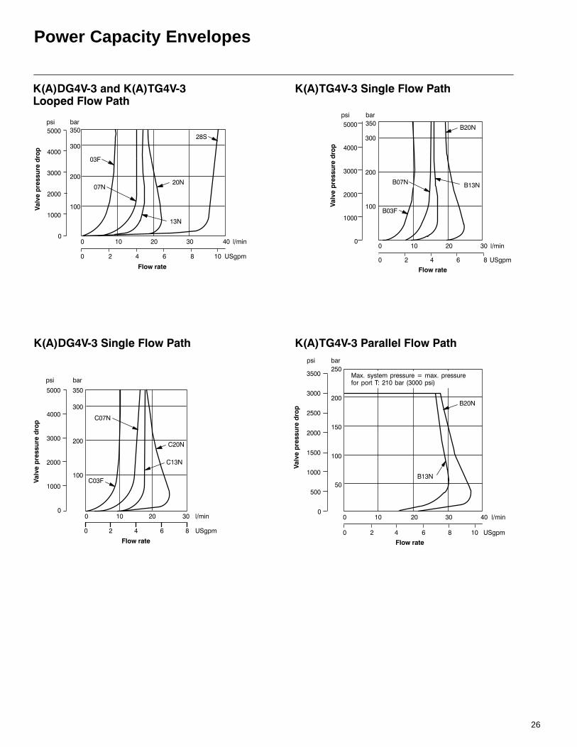
Power Capacity Envelopes
).&"#$%
$0((1
. . 0. .
. 0 - /
8),
...
-...
...
0...
...
.
.
..
0..
..
3.2
3. 1
30.
3
, %
$0((1
...
-...
...
0...
...
.
.
..
0..
..
. . 0. . -.
. 0 - / 8),.
. 1
.2
0)
0.
, %
).&"#$% ).!"#$%
).!"#$%
&0.
& &.2
&. 1
$0((1
...
-...
...
0...
...
.
.
..
0..
..
, %
. 0 - / 8),
. . 0. .
).!"#$%
&0.
&
. . 0. . -.
. 0 - / 8),.
$0((1
..
...
0..
0...
..
...
..
.
0.
0..
.
..
.
, %
>6# ,9?6#,9,'0.%4 ...,7
27
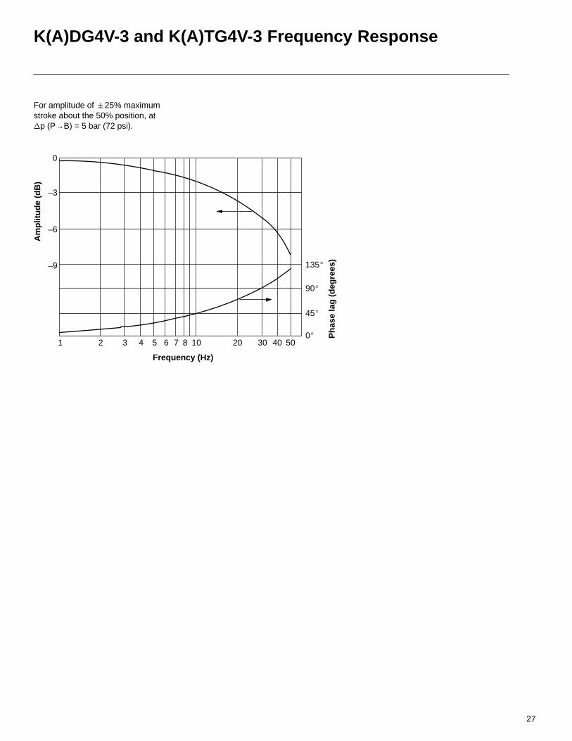
K(A)DG4V-3 and K(A)TG4V-3 Frequency Response
For amplitude of 25% maximum stroke about the 50% position, at p (P→B) = 5 bar (72 psi).
Am
plit
ud
e (d
B)
Frequency (Hz)
1 2 3 4 5 6 7 8 10 20 30 40 50
0
–3
–6
–9
0
45
135
90
Ph
ase
lag
(d
egre
es)
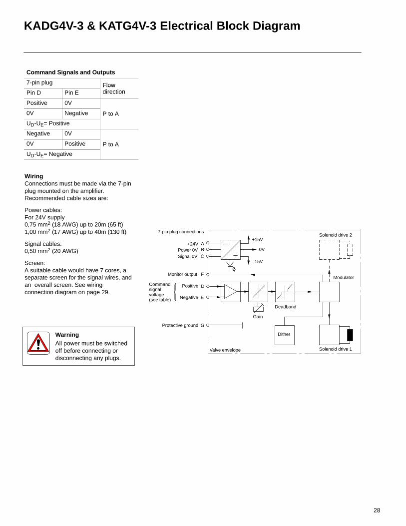
WiringConnections must be made via the 7-pinplug mounted on the amplifier.Recommended cable sizes are:
Power cables:For 24V supply0,75 mm2 (18 AWG) up to 20m (65 ft)1,00 mm2 (17 AWG) up to 40m (130 ft)
Signal cables:0,50 mm2 (20 AWG)
Screen:A suitable cable would have 7 cores, aseparate screen for the signal wires, andan overall screen. See wiringconnection diagram on page 29.
Gain
Modulator
+15V
Valve envelope
7-pin plug connections
+24V APower 0VSignal 0V
Protective ground
Solenoid drive 2
Deadband
Positive
Monitor output
Negative
Commandsignalvoltage(see table)
–15V
0V
Solenoid drive 1
BC
F
D
E
G
Dither
28
KADG4V-3 & KATG4V-3 Electrical Block Diagram
Command Signals and Outputs
7-pin plug FlowPin D Pin E
Flowdirection
Positive 0V
0V Negative P to A
UD-UE= Positive
Negative 0V
0V Positive P to A
UD-UE= Negative
WarningAll power must be switchedoff before connecting ordisconnecting any plugs.
29
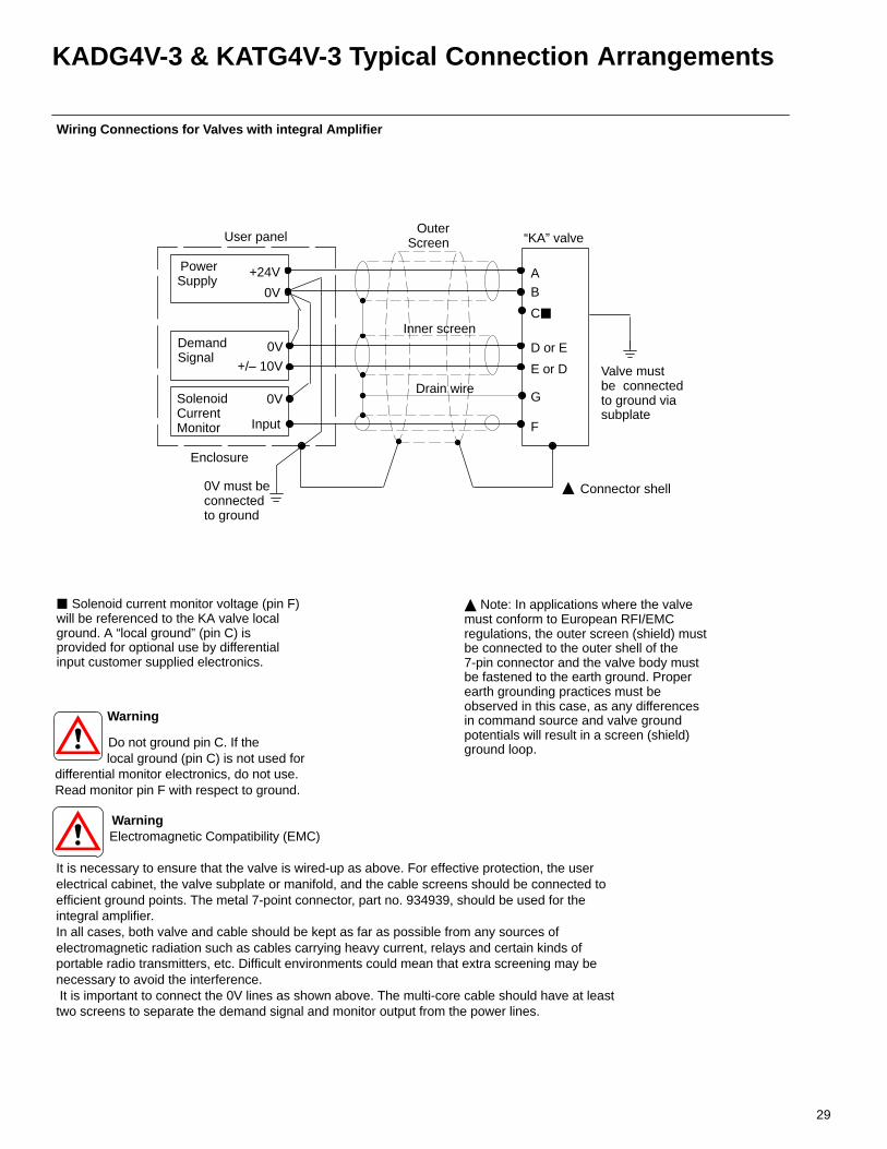
KADG4V-3 & KATG4V-3 Typical Connection Arrangements
Warning
Do not ground pin C. If the local ground (pin C) is not used fordifferential monitor electronics, do not use.Read monitor pin F with respect to ground.
User panelOuter
Screen “KA” valve
AB
F
G
D or E
E or D
C
+24V
0V
DemandSignal
SolenoidCurrentMonitor
PowerSupply
Enclosure
Valve mustbe connectedto ground viasubplate
0V
Input
+/– 10V
0V
Connector shell
Solenoid current monitor voltage (pin F)will be referenced to the KA valve localground. A “local ground” (pin C) isprovided for optional use by differentialinput customer supplied electronics.
Wiring Connections for Valves with integral Amplifier
Note: In applications where the valvemust conform to European RFI/EMCregulations, the outer screen (shield) mustbe connected to the outer shell of the7-pin connector and the valve body mustbe fastened to the earth ground. Properearth grounding practices must beobserved in this case, as any differencesin command source and valve groundpotentials will result in a screen (shield)ground loop.
0V must beconnectedto ground
Warning Electromagnetic Compatibility (EMC) It is necessary to ensure that the valve is wired-up as above. For effective protection, the userelectrical cabinet, the valve subplate or manifold, and the cable screens should be connected toefficient ground points. The metal 7-point connector, part no. 934939, should be used for theintegral amplifier.In all cases, both valve and cable should be kept as far as possible from any sources ofelectromagnetic radiation such as cables carrying heavy current, relays and certain kinds ofportable radio transmitters, etc. Difficult environments could mean that extra screening may benecessary to avoid the interference. It is important to connect the 0V lines as shown above. The multi-core cable should have at leasttwo screens to separate the demand signal and monitor output from the power lines.
Drain wire
Inner screen

30
KDG4V-3 and KTG4V-3 Installation Dimensions
16,8 (0.66)
3rd angleprojection
24,0(0.94)
24.5(0.96)
21,75(0.86)
48,00(1.9)
KDG4V-3Dimensions in mm (inches)
Plug connector can be repositioned in 90° increments by loosening knurlednut, turning coil, and re-tightening.
164,0 (6.46) without override
74,0 (2.9)
51.0(2.0)
35,0(1.4)
13,0 (0.50) forplug removal
Seal
51(2.01)
27(1.06)
22,5(0.88)∅
M3 thread 5,5(0.22)
1,5(0.06)
30,5(1.20)
26,5(1.04)
27,5(1.08)
18(0.71)
DIN 43650 plug connector is notincluded with valve and must be ordered separately. For black plugmarked B, order part 710775. For grayplug marked A, order part 710776.
Conductor cross-sectional area:0,5 to 1,5 mm2 (0.0008 to 0.0023 in2)
Cable diameter range:6 to 10 mm (0.24 to 0.40 in)
To bleed air, loosen plug in end of core tube; re-tighten after bleeding is complete.
74,0 (2.9)
16,8 (0.66)
98,8 (3.89)
238,0 (9.37) without overrides
10,0 (0.4) for plainmanual override
10,0 (0.4) for plainmanual override
61,0 (2.4) for coil removal
14,0 (0.55) for weather-resistant manual overrides
14,0 (0.55) for weather-resistant manual overrides
24,5 (0.96)
61,0 (2.4) for coil removal
21,75(0.86)
51,0 (2.0)
35,0(1.4)
13,0 (0.5) for plug removal
∅ 5,6 (0.22) thru.∅ 9,0 (0.35) c’boreto depth shown.4 places
98,87 (3.89)
∅ 5,6 (0.22) thru. ∅ 9,0 (0.35) c’boreto depth shown. 4 places
Plug connector can be repositioned in 90° increments by loosening knurled nut, turning coil, and re-tightening.
10,0 (0.4) for plainmanual override
14,0 (0.55) for weather-resistantmanual overrides
61,0 (2.4) for coil removal
Means of connection: screw terminals
KTG4V-3Dimensions in mm (inches)
Solenoid Plug ConnectorsDimensions in mm (inches)
31
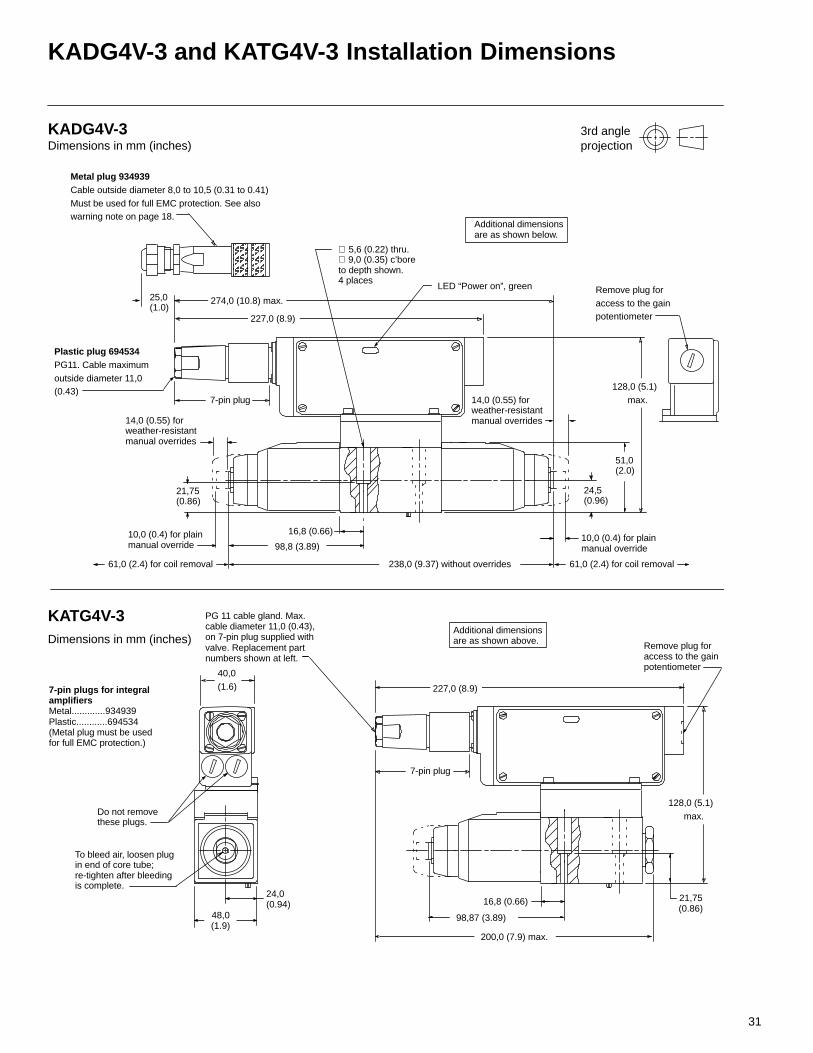
KADG4V-3 and KATG4V-3 Installation Dimensions
Metal plug 934939Cable outside diameter 8,0 to 10,5 (0.31 to 0.41)Must be used for full EMC protection. See alsowarning note on page 18.
Plastic plug 694534PG11. Cable maximumoutside diameter 11,0(0.43)
7-pin plug
40,0(1.6)
16,8 (0.66)
16,8 (0.66)
98,8 (3.89)
238,0 (9.37) without overrides
10,0 (0.4) for plainmanual override
10,0 (0.4) for plainmanual override
61,0 (2.4) for coil removal
14,0 (0.55) for weather-resistant manual overrides
14,0 (0.55) for weather-resistant manual overrides
24,5 (0.96)
61,0 (2.4) for coil removal
21,75(0.86)
51,0 (2.0)
∅ 5,6 (0.22) thru.∅ 9,0 (0.35) c’boreto depth shown.4 places
Remove plug foraccess to the gainpotentiometer227,0 (8.9)
LED “Power on”, green
274,0 (10.8) max.
128,0 (5.1) max.
Do not removethese plugs.
PG 11 cable gland. Max.cable diameter 11,0 (0.43),on 7-pin plug supplied withvalve. Replacement partnumbers shown at left.
3rd angleprojection
24,0(0.94)
21,75(0.86)
To bleed air, loosen plug in end of core tube; re-tighten after bleeding is complete.
98,87 (3.89)
KATG4V-3Dimensions in mm (inches)
7-pin plugs for integralamplifiers Metal.............934939Plastic............694534(Metal plug must be usedfor full EMC protection.)
227,0 (8.9)
48,0(1.9)
128,0 (5.1) max.
200,0 (7.9) max.
Additional dimensionsare as shown above. Remove plug for
access to the gainpotentiometer
Additional dimensionsare as shown below.ÂÂ
ÂÂÂÂ
ÂÂÂÂÂÂ
25,0 (1.0)
7-pin plug
KADG4V-3Dimensions in mm (inches)
32
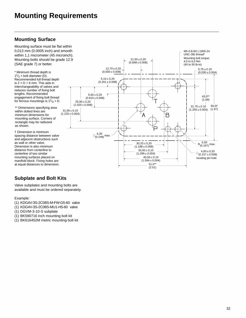
Mounting Requirements
12,700,20(0.5000.008)
5,100,20(0.2010.008)
0,750.10(0.0300.004)
M5-0.8-6H (.1900-24UNC-2B) thread*
* Minimum thread depth is11/2 × bolt diameter (D).Recommended full thread depth is 2 × D + 6 mm. This aids ininterchangeability of valves andreduces number of fixing boltlengths. Recommendedengagement of fixing bolt threadfor ferrous mountings is 11/4 × D.
6,30(0.248)∅ max.
5,00(0.197)R max.
4,000,20(0.1570.008)∅
locating pin hole
** Dimensions specifying areawithin dotted lines areminimum dimensions formounting surface. Corners ofrectangle may be radiused as shown.
Dimension is minimumspacing distance between valveand adjacent obstructions suchas wall or other valve.Dimension is also minimumdistance from centerline tocenterline of two similarmounting surfaces placed onmanifold block. Fixing holes areat equal distances to dimension.
5,500,20(0.6100.008)
25,900,20(1.0200.008)
31,000,10(1.2200.004)
21,500,20(0.8480.008)
30,200,20(1.1880.008)
33,000,10(1.2990.004)
40,500,10(1.5940.004)
51,0**(2.01)
50,0(1.97)
31,750.10(1.2500.004)
43,0**(1.69)
Mounting bolt torque:4,5 to 6,0 Nm(40 to 50 lb-in)
Mounting SurfaceMounting surface must be flat within0,013 mm (0.0005 inch) and smoothwithin 1,1 micrometer (45 microinch).Mounting bolts should be grade 12.9(SAE grade 7) or better.
Subplate and Bolt KitsValve subplates and mounting bolts areavailable and must be ordered separately.
Example:(1) KDG4V-3S-2C08S-M-FW-G5-60 valve(1) KDG4V-3S-2C08S-MU1-H5-60 valve(1) DGVM-3-10-S subplate(1) BK590716 inch mounting bolt kit (1) BK616452M metric mounting bolt kit
33
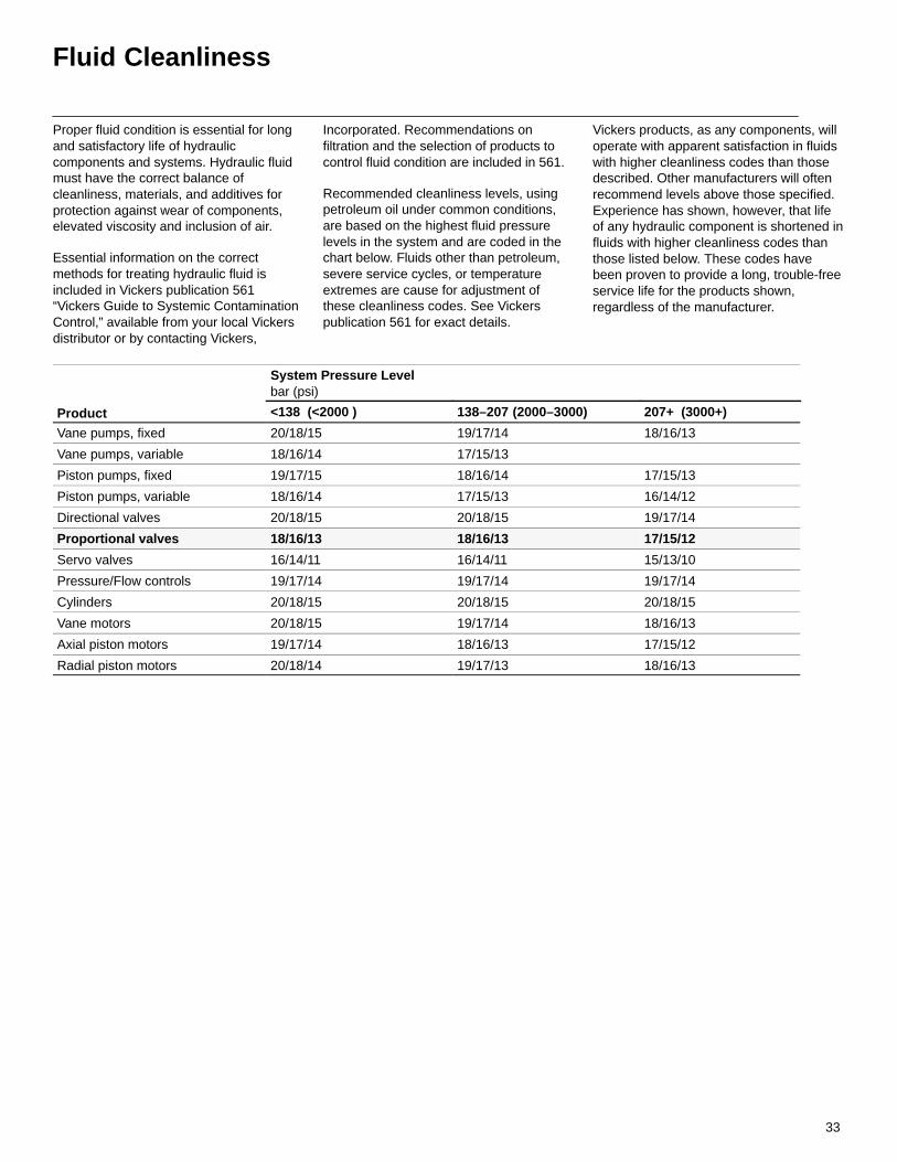
Fluid Cleanliness
Proper fluid condition is essential for longand satisfactory life of hydrauliccomponents and systems. Hydraulic fluidmust have the correct balance ofcleanliness, materials, and additives forprotection against wear of components,elevated viscosity and inclusion of air.
Essential information on the correctmethods for treating hydraulic fluid isincluded in Vickers publication 561“Vickers Guide to Systemic ContaminationControl,” available from your local Vickersdistributor or by contacting Vickers,
Incorporated. Recommendations onfiltration and the selection of products tocontrol fluid condition are included in 561.
Recommended cleanliness levels, usingpetroleum oil under common conditions,are based on the highest fluid pressurelevels in the system and are coded in thechart below. Fluids other than petroleum,severe service cycles, or temperatureextremes are cause for adjustment ofthese cleanliness codes. See Vickerspublication 561 for exact details.
Vickers products, as any components, willoperate with apparent satisfaction in fluidswith higher cleanliness codes than thosedescribed. Other manufacturers will oftenrecommend levels above those specified.Experience has shown, however, that lifeof any hydraulic component is shortened influids with higher cleanliness codes thanthose listed below. These codes havebeen proven to provide a long, trouble-freeservice life for the products shown,regardless of the manufacturer.
System Pressure Levelbar (psi)
Product <138 (<2000 ) 138–207 (2000–3000) 207+ (3000+)
Vane pumps, fixed 20/18/15 19/17/14 18/16/13
Vane pumps, variable 18/16/14 17/15/13
Piston pumps, fixed 19/17/15 18/16/14 17/15/13
Piston pumps, variable 18/16/14 17/15/13 16/14/12
Directional valves 20/18/15 20/18/15 19/17/14
Proportional valves 18/16/13 18/16/13 17/15/12
Servo valves 16/14/11 16/14/11 15/13/10
Pressure/Flow controls 19/17/14 19/17/14 19/17/14
Cylinders 20/18/15 20/18/15 20/18/15
Vane motors 20/18/15 19/17/14 18/16/13
Axial piston motors 19/17/14 18/16/13 17/15/12
Radial piston motors 20/18/14 19/17/13 18/16/13
Top Related