


Languages
Pages
Legal

Power Cables For PowerFlex 4, 40, 400, 52x, 70, 700, and 75x Series
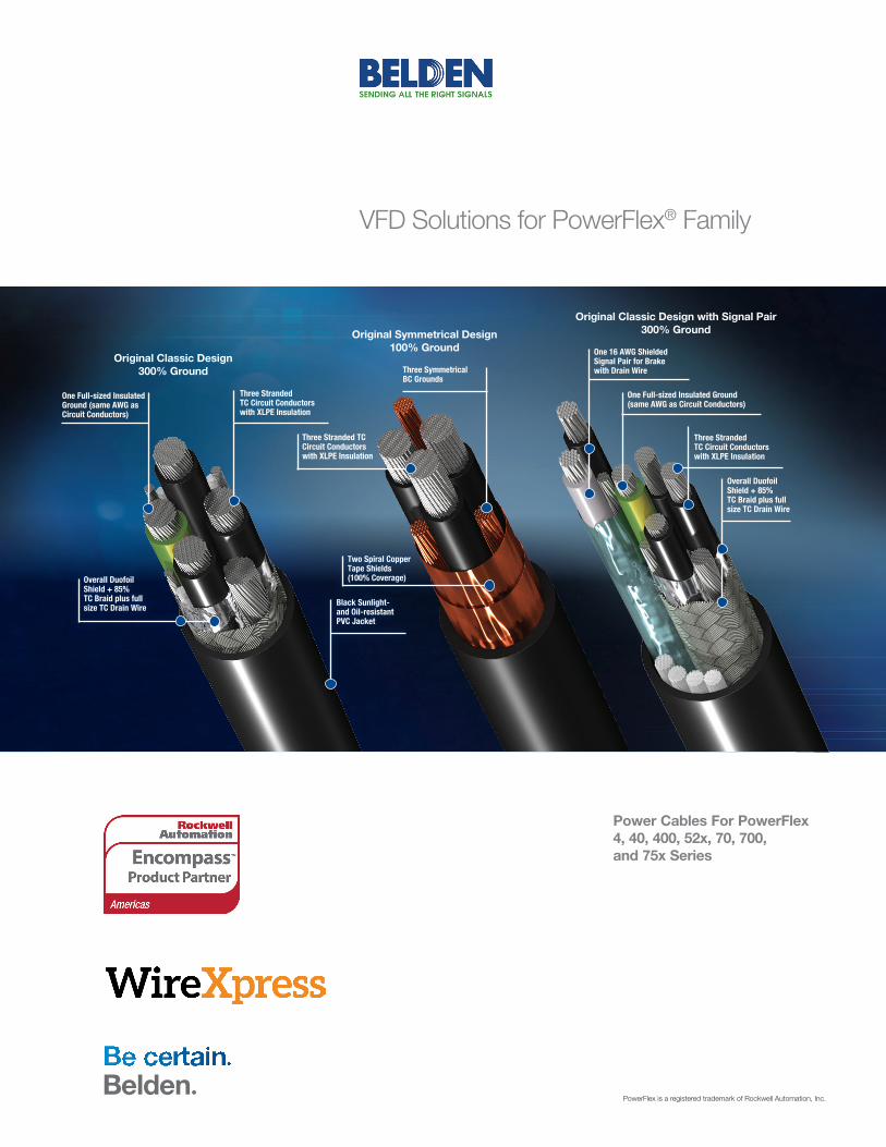
VFD Solutions for PowerFlex® Family
Black Sunlight- and Oil-resistant PVC Jacket
Three Stranded TC Circuit Conductors with XLPE Insulation
Overall Duofoil Shield + 85% TC Braid plus full size TC Drain Wire
Three Stranded TC Circuit Conductors with XLPE Insulation
Two Spiral Copper Tape Shields (100% Coverage)
One Full-sized Insulated Ground (same AWG as Circuit Conductors)
Three Symmetrical BC Grounds
One 16 AWG Shielded Signal Pair for Brake with Drain Wire
One Full-sized Insulated Ground (same AWG as Circuit Conductors)
Three Stranded TC Circuit Conductors with XLPE Insulation
Overall Duofoil Shield + 85% TC Braid plus full size TC Drain Wire
Original Classic Design300% Ground
Original Symmetrical Design100% Ground
Original Classic Design with Signal Pair300% Ground
PowerFlex is a registered trademark of Rockwell Automation, Inc.
Why Use a Specially Designed VFD Cable?
Variable frequency AC motor drives generate significant electrical noise that can create issues with associated or near by equipment, affect operational reliability, and lead to system failures or downtime. Typical cabling solutions for this application have been unshielded tray cables, single-conductor lead wire installed in conduit or shielded tray. These solutions suffer from complex, costly installation and potential noise and reliability problems. Belden VFD Cables were designed and engineered to overcome these challenges.
The Main Challenges of VFD Applications
• Common mode current containment (CMC)
• Capacitive coupling and cable charging
• Reflective wave voltage
• Installation reliability and safety
VFD cables must handle not only the overall high power levels of the pulse-width modulated (PWM) VFD signals, but also the extremely high voltage which can occur when reflected waves develop on the conductors. This high voltage can cause
corona discharge between the conductors of conventional cables, causing damage not only to the cabling itself, but also to the motors, bearings, drives and related equipment. In turn, this damage can cause failure of the entire drive system, resulting in costly production downtime.
Limitations of Conventional VFD Cables
In addition to experiencing failures due to corona discharge and adverse environmental condition, conventional cabling is difficult and expensive to install. Armored cable and lead wire in conduit are cumbersome and heavy, plus require extremely large installation bending radii making installation both time-consuming and labor intensive. Yet they still do not solve noise and corona discharge problems, nor do they effectively address the high levels of noise generated by VFDs.
The Belden VFD Solution
Only Belden’s series of VFD Cable provide the robust construction required to deliver superior electrical performance and reliability, even in the most demanding industrial environments.
Application Designed Grounding and Shielding
• Provides more grounding copper than other designs, ensuring the best containment of electrical noise
Thicker, Industrial-grade XLP Insulation
• Provides more stable electrical performance than PVC
• Lower capacitance resulting in :
• Longer cable runs
• Reduced peak motor terminal voltage for extended motor life
• Reduced likelihood of corona discharge
• Reduced magnitude of reflected waves
• Increased efficiency of power transfer
High-strand Tinned Copper Circuit Conductors
• Superior high frequency transmission path for better CMC containment
• Higher flex life, better vibration resistance and easier installation
• Corrosion resistant for reliable termination
Power Cables
Industrial-Grade PVC or Optional HaloarrestXLink™ Low Smoke Zero Halogen (LSZH) Jackets
VFD Cable Types:
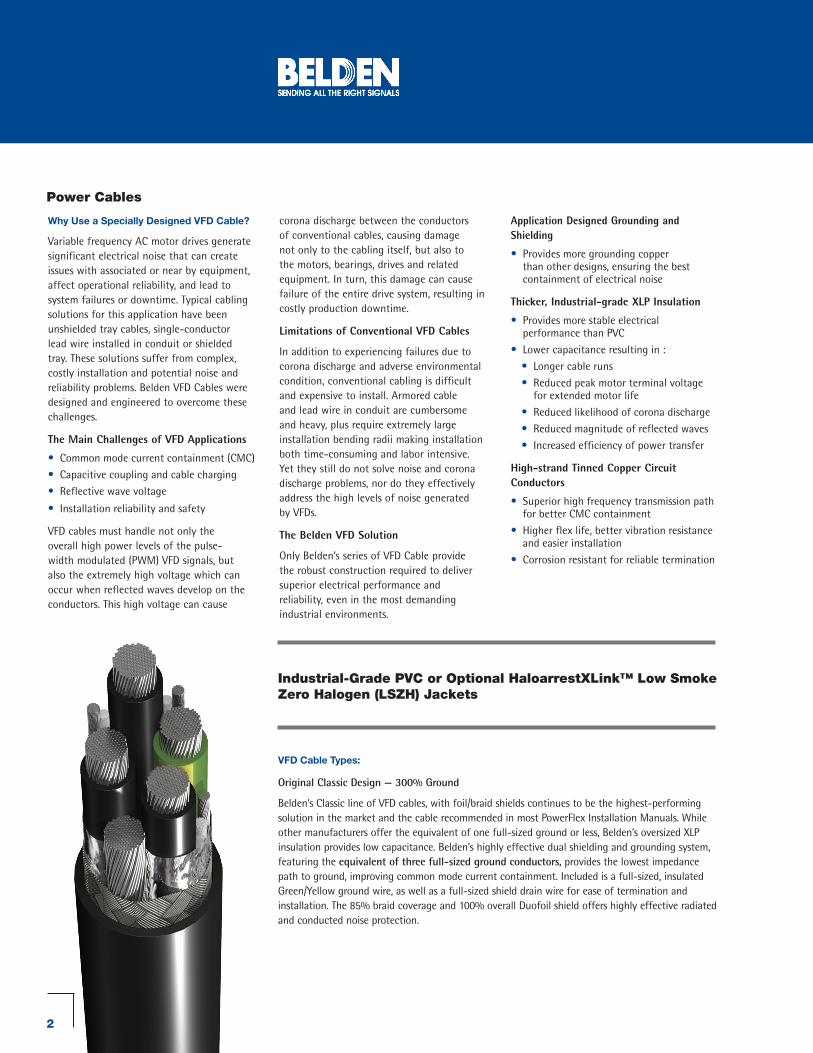
Original Classic Design — 300% Ground
Belden’s Classic line of VFD cables, with foil/braid shields continues to be the highest-performing solution in the market and the cable recommended in most PowerFlex Installation Manuals. While other manufacturers offer the equivalent of one full-sized ground or less, Belden’s oversized XLP insulation provides low capacitance. Belden’s highly effective dual shielding and grounding system, featuring the equivalent of three full-sized ground conductors, provides the lowest impedance path to ground, improving common mode current containment. Included is a full-sized, insulated Green/Yellow ground wire, as well as a full-sized shield drain wire for ease of termination and installation. The 85% braid coverage and 100% overall Duofoil shield offers highly effective radiated and conducted noise protection.
2
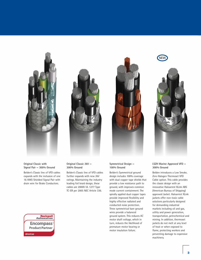
LSZH Marine Approved VFD — 300% Ground
Belden introduces a Low Smoke, Zero Halogen Thermoset VFD Cable option. This cable provides the classic design with an innovative Haloarrest XLink ABS (American Bureau of Shipping) approved Jacket. Haloarrest XLink jackets offer non-toxic cable solutions particularly designed for demanding industrial markets including oil and gas, utility and power generation, transportation, petrochemical and mining. In addition, thermoset jackets do not melt at any level of heat or when exposed to flame, protecting workers and preventing damage to expensive machinery.
NEW
Original Classic 2kV — 300% Ground
Belden’s Classic line of VFD cables further expands with new 2kV ratings. Maintaining the industry leading foil braid design, these cables are 2000V UL 1277 Type TC-ER per 2005 NEC Article 336.
Symmetrical Design — 100% Ground
Belden’s Symmetrical ground design includes 100% coverage with dual copper tape shields that provide a low resistance path to ground, with improves common mode current containment. The spirally applied dual copper tapes provide improved flexibility and highly effective radiated and conducted noise protection. Three symmetrical bare ground wires provide a balanced ground system. This reduces AC motor shaft voltage, which in turn, reduces the likelihood of premature motor bearing or motor insulation failure.
Original Classic with Signal Pair — 300% Ground
Belden’s Classic line of VFD cables expands with the inclusion of one 16 AWG Shielded Signal Pair with drain wire for Brake Conductors.
3
Be Certain with Belden
Selecting a VFD Cable:
While there are many factors that go into selecting the appropriate VFD cable for your application, the fundamental selection should be based on three key pieces of information:
• Motor HP
• Motor Voltage
• Motor Full Load Current (FLC) from NEC® section 430.250 FLC.
Using this you may select a cable gauge size and then correct for other factors.
Examples of additional factors include: ambient temperature, VFD cable and connector ratings, and the number of cables within the raceway.
(See correction and adjustment factors on page 5)
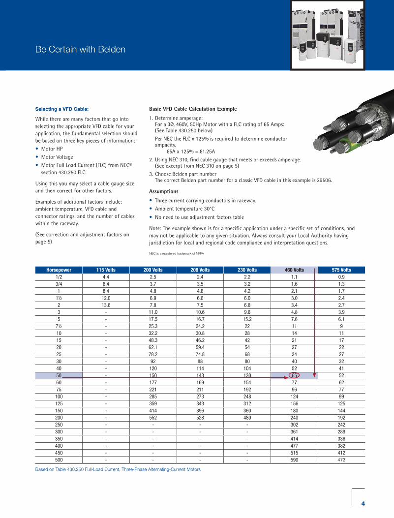
Based on Table 430.250 Full-Load Current, Three-Phase Alternating-Current Motors
Horsepower 115 Volts 200 Volts 208 Volts 230 Volts 460 Volts 575 Volts1/2 4.4 2.5 2.4 2.2 1.1 0.93/4 6.4 3.7 3.5 3.2 1.6 1.31 8.4 4.8 4.6 4.2 2.1 1.7
1½ 12.0 6.9 6.6 6.0 3.0 2.42 13.6 7.8 7.5 6.8 3.4 2.73 - 11.0 10.6 9.6 4.8 3.95 - 17.5 16.7 15.2 7.6 6.1
7½ - 25.3 24.2 22 11 910 - 32.2 30.8 28 14 1115 - 48.3 46.2 42 21 1720 - 62.1 59.4 54 27 2225 - 78.2 74.8 68 34 2730 - 92 88 80 40 3240 - 120 114 104 52 4150 - 150 143 130 65 5260 - 177 169 154 77 6275 - 221 211 192 96 77100 - 285 273 248 124 99125 - 359 343 312 156 125150 - 414 396 360 180 144200 - 552 528 480 240 192250 - - - - 302 242300 - - - - 361 289350 - - - - 414 336400 - - - - 477 382450 - - - - 515 412500 - - - - 590 472
Basic VFD Cable Calculation Example
1. Determine amperage: For a 3Ø, 460V, 50Hp Motor with a FLC rating of 65 Amps: (See Table 430.250 below)
Per NEC the FLC x 125% is required to determine conductor ampacity. 65A x 125% = 81.25A
2. Using NEC 310, find cable gauge that meets or exceeds amperage. (See excerpt from NEC 310 on page 5)
3. Choose Belden part number The correct Belden part number for a classic VFD cable in this example is 29506.
Assumptions
• Three current carrying conductors in raceway.
• Ambient temperature 30°C
• No need to use adjustment factors table
Note: The example shown is for a specific application under a specific set of conditions, and may not be applicable to any given situation. Always consult your Local Authority having jurisdiction for local and regional code compliance and interpretation questions.
NEC is a registered trademark of NFPA
4
Be Certain with Belden
Conductor Rating (Amps)+
Conductor Gauge Size
Classic VFD Part No. UL/CSA
(Recommended for PowerFlex Drives)
Classic w/Signal Pair Part No. UL 2kV VFD Part No. UL Symmetrical VFD
Part No. CSAThermoset LSZH VFD Marine Approvals UL
18 - - - - - -
20 **14 29501 29511 29536 29550C 29501X
25 **12 29502 29512 29537 29551C 29502X
35 **10 29503 29513 29538 29552C 29503X
50 8 29504 - 29539 29553C 29504X
65 6 29505 - 29540 29554C 29505X
85 4 29506 - 29541 29555C 29506X
115 2 29507 - 29542 29556C 29507X
130 1 29528 - 29543 29557C 29528X
150 1/0 29529 - 29544 29558C 29529X
175 2/0 29530 - 29545 29559C 29530X
200 3/0 29531 - 29546 29560C 29531X
230 4/0 29532 - 29547 29561C 29532X
255 250 MCM - - 29533 29533 -
310 350 MCM - - 29534 29534 -
380 500 MCM - - 29535 29535 -
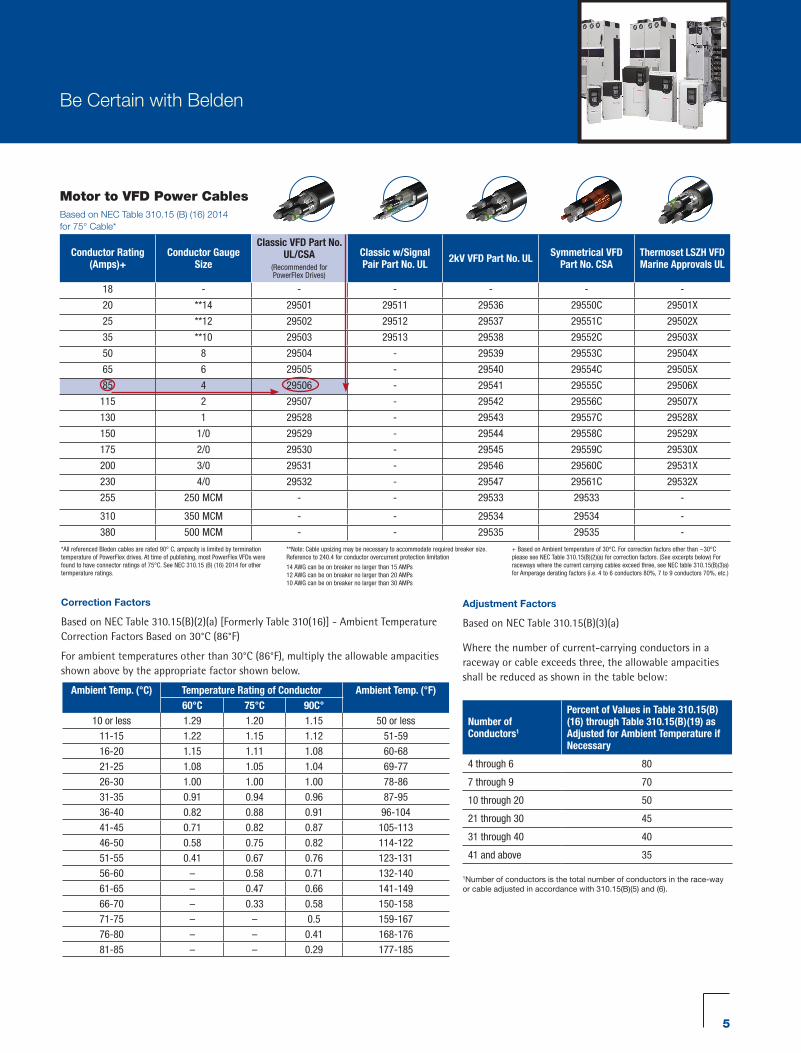
*All referenced Bleden cables are rated 90° C, ampacity is limited by termination temperature of PowerFlex drives. At time of publishing, most PowerFlex VFDs were found to have connector ratings of 75°C. See NEC 310.15 (B) (16) 2014 for other termperature ratings.
**Note: Cable upsizing may be necessary to accommodate required breaker size. Reference to 240.4 for conductor overcurrent protection limitation
14 AWG can be on breaker no larger than 15 AMPs 12 AWG can be on breaker no larger than 20 AMPs 10 AWG can be on breaker no larger than 30 AMPs
+ Based on Ambient temperature of 30°C. For correction factors other than ~30°C please see NEC Table 310.15(B)(2)(a) for correction factors. (See excerpts below) For raceways where the current carrying cables exceed three, see NEC table 310.15(B)(3)a) for Amperage derating factors (i.e. 4 to 6 conductors 80%, 7 to 9 conductors 70%, etc.)
Motor to VFD Power CablesBased on NEC Table 310.15 (B) (16) 2014 for 75° Cable*
Correction Factors
Based on NEC Table 310.15(B)(2)(a) [Formerly Table 310(16)] - Ambient Temperature Correction Factors Based on 30°C (86°F)
For ambient temperatures other than 30°C (86°F), multiply the allowable ampacities shown above by the appropriate factor shown below.
Ambient Temp. (°C) Temperature Rating of Conductor Ambient Temp. (°F)60°C 75°C 90C°
10 or less 1.29 1.20 1.15 50 or less
11-15 1.22 1.15 1.12 51-59
16-20 1.15 1.11 1.08 60-68
21-25 1.08 1.05 1.04 69-77
26-30 1.00 1.00 1.00 78-86
31-35 0.91 0.94 0.96 87-95
36-40 0.82 0.88 0.91 96-104
41-45 0.71 0.82 0.87 105-113
46-50 0.58 0.75 0.82 114-122
51-55 0.41 0.67 0.76 123-131
56-60 – 0.58 0.71 132-140
61-65 – 0.47 0.66 141-149
66-70 – 0.33 0.58 150-158
71-75 – – 0.5 159-167
76-80 – – 0.41 168-176
81-85 – – 0.29 177-185
Adjustment Factors
Based on NEC Table 310.15(B)(3)(a)
Where the number of current-carrying conductors in a raceway or cable exceeds three, the allowable ampacities shall be reduced as shown in the table below:
Number of Conductors1
Percent of Values in Table 310.15(B)(16) through Table 310.15(B)(19) as Adjusted for Ambient Temperature if Necessary
4 through 6 80
7 through 9 70
10 through 20 50
21 through 30 45
31 through 40 40
41 and above 35
1Number of conductors is the total number of conductors in the race-way or cable adjusted in accordance with 310.15(B)(5) and (6).
5

Encoder Cables
Catalog Number Description Notes
8790 18 AWG, 1 pair (Power Supply) See Drives Manufacturer’s recommended cable construction
9729 24 AWG, 2 pair
9730, 89730 24 AWG, 3 pair
9728 24 AWG, 4 pair
9892 20 AWG, 4 pair
9860 16 AWG, 1 pair (signal)
Phone: 1.800.BELDEN1 www.Belden.com
©Copyright 2014, Belden Inc. VFD-SOLUTIONS-FOR-POWERFLEX-FAMILY_BR_INCA_BDC_1014_A_AG
Communication Adapters and Cables
Catalog Number Description Belden Comm. Cable
20-COMM-C PowerFlex 7x ControlNet Copper to DPI Communication Adapter 3092A
20-COMM-Q PowerFlex 7x ControlNet Fiber to DPI Communication Adapter 62.5 μm Duplex: B96915
20-COMM-D PowerFlex 7x DeviceNet Communication Adapter 3084A
20-COMM-E PowerFlex 7x EtherNet/IP to DPI Communication Adapter Reel/Cut: 7958A
20-COMM-E PowerFlex 7x EtherNet/IP to DPI Communication Adapter Cordset: E5050xx 010A1
20-COMM-P PowerFlex 7x Profibus Adapter 3079A
20-COMM-R PowerFlex 7x Remote I/O Communication Adapter 9463
20-COMM-S PowerFlex 7x RS-485 DF1 Communication Adapter 3107A
20-COMM-K PowerFlex 7x CANOpen Communication Adapter 3107A
20-COMM-M PowerFlex 7x Modbus/TCP Communication Adapter 8777
0-10V DC or / 4-20 mA Signal Cables
Catalog Number Description Notes:
8760 1 pair, 18 AWG Stranded Tinned Conductors, Polyolefin Insulation, overall Beldfoil® shield, Drain Wire and PVC Jacket 300V UL AWM 60°C
8770 3 conductor, 18 AWG Stranded Tinned conductors, Polyolefin Insulation, overall Beldfoil shield, Drain Wire and PVC Jacket 300V UL AWM 60°C
Communication and Control Cables
Number of Conductors1
Percent of Values in Table 310.15(B)(16) through Table 310.15(B)(19) as Adjusted for Ambient Temperature if Necessary
4 through 6 80
7 through 9 70
10 through 20 50
21 through 30 45
31 through 40 40
41 and above 35
1Number of conductors is the total number of conductors in the race-way or cable adjusted in accordance with 310.15(B)(5) and (6).
6
Top Related