


Languages
Pages
Legal


Fox DHX Coil Rebuild Introduction:
This is a guide to tearing down and rebuilding a Fox Racing Shox DHX 3/4/5 Coil shock. It shows the user how to:
-‐ Dismantle the shock
-‐ Clean internal parts -‐ Disassemble the Propedal valve and spring
-‐ Disassemble the Rebound assembly (see disclaimer) -‐ Replace internal o-‐rings -‐ Replace main shaft seal o-‐ring -‐ Replace oil -‐ Reassembly of the shock unit
Note:
Disclaimer:
Fox Racing Shox does not endorse this guide!
By proceeding with this guide, the instant you open your shock, you voluntarily and knowingly forfeit any warranty that came with the shock.
Rebound Disassembly requires the use of a propane torch to soften loctite used to secure rebound adjuster eyelet to
shock shaft. Soften of the loctite is required to remove the eyelet. BE EXTREMELY CAREFUL WHEN HEATING THE EYELET; ONLY HEAT GENTLY UNTIL IT IS HOT TO TOUCH. PROLONGED HEATING WILL CAUSE DAMAGE TO EYELET
AND SHAFT ASSEMBLY.
Do not proceed with these procedures if you are not mechanically inclined!
If you have a tendency to round/strip every screw you touch, put the tools down NOW! Any damage you cause to
your shock due to your own mistakes is YOUR FAULT. Do not expect any sympathy from me, or any sympathy from Fox (or warranty). YOU have to pay to have the unit fixed. This guide was devised with care, with information gained
from a number of sources. This procedure works if carried out CAREFULLY and with PATIENCE.
I AM NOT RESPONSIBLE FOR ANY DAMAGE YOU CAUSE TO YOUR SHOCK, BIKE, PERSONA OR SURROUNDS, USE COMMON SENSE AND TAKE THE FIRST FEW RIDES EASY, TO ENSURE YOU HAVE CORRECTLY REPAIRED THE SHOCK.
WARNING!
READ ALL Instructions twice before you commence with the rebuild, and ensure you understand its procedures
PDF compression, OCR, web optimization using a watermarked evaluation copy of CVISION PDFCompressor

Preliminaries
Tool list:
-‐ Spanners -‐ Long Nose Snap ring pliers -‐ Small block of wood (to create makeshift shaft clamp) -‐ Propane torch -‐ Loctite thread lock -‐ Wooden vice
-‐ Soft jaw vice -‐ Long nose pliers -‐ O-‐ring / Dental picks (for removal of o-‐rings) -‐ Clean rags -‐ Clean work bench -‐ Oil drip Pan -‐ Safety glasses -‐ Small Breaker Bar
-‐ 11mm Drill bit
Parts list:
-‐ Replacement o-‐rings, the best way to get these is to take the removed o-‐rings to a local 0-‐ring supplier and get
them sized up properly for replacement ones, I also recommend you buy a good amount of each, it’s always good to have spares for next time, label them and put them in a compartment container
-‐ Fork/shock oil. Ensure you use a high quality, fully synthetic oil. I use 10W Castrol Fully synthetic fork fluid. The DHX comes stock with 10W Fox Fluid (rebadged Silkolene pro RSF 10) If you wish to use a different weight oil,
this sight has a lot of useful info on shock oil; http://www.peterverdonedesigns.com/bikesuspension.htm-‐
Further Information:
Here is a list of websites that have a lot of useful information on rear shocks, for anyone who is interested in learning
more about their rear shocks.
• Information on EVERYTHING regarding suspension, explaining different types of damper systems, set
up info on a range of shocks etc; these site’s are well worth reading through! :
http://www.krankin.co.nz/_sgt/m6m9_1.htm
http://users.actrix.co.nz/dougal.ellen/setup.html
http://users.actrix.co.nz/dougal.ellen/tuning.html
• Some useful info on how to mod shim stacks, for those who are interested in modifying their shim:
stacks, (undertake this at your own risk!)
http://www.deycore.com/tuning_tips.htm
• Website with lots of info regarding things like oil weights etc:
http://www.peterverdonedesigns.com/bikesuspension.htm
Righto, if you feel confident, and have read this guide at least twice (yes that was an instruction!), clean your
work area, gather your tools, and lets begin! PDF compression, OCR, web optimization using a watermarked evaluation copy of CVISION PDFCompressor

STEP 1: Removing shock
1. Firstly, you will need to remove shock from your bike; it will be different on every bike, so if you don’t know how to remove your shock, STOP NOW!
2. After you have removed the shock from the bike, place on your work bench, and give it a good wipe over with a clean cloth, to remove dust and dirt
3. Next remove you spring, and in my case, my shock boot
4. Back off all adjustments (Least Propedal, Bottom Out and Rebound)
5. DEFLATE THE BOOST VALVE!
6. Give the shock body a good clean, you don’t need any dirt or debris’s getting inside the shock
7. Clamp the shock body in a wooden vice
PDF compression, OCR, web optimization using a watermarked evaluation copy of CVISION PDFCompressor

STEP 2: Removing Bottom Out Adjuster
8. Loosen the two grub screws on the bottom out adjuster with a hex key
9. Remove the adjuster, and set it aside
10. Using either a spanner or wrench, loosen the grey cap
11. After the threads have been disengaged, pull the assembly out, and set it aside
12. You can now see the IFP (Internal Floating Piston) and the bleed screw in the middle
13. Use a measuring device and measure the depth of the IFP, The depth will be different for different stroke lengths and eye to eye measurements
PDF compression, OCR, web optimization using a watermarked evaluation copy of CVISION PDFCompressor

STEP 3: Removing the IFP
14. Depress the shaft all the way down
15. Remove the bleed screw from the centre of the IFP with a hex key
16. Pull the bleed screw out, and set it aside in a safe place
17. Using long needle nosed pliers, pull the IFP out of the Piggyback Chamber
18. Remove the IFP
19. Place the IFP aside, and pull the shaft out to full extension
PDF compression, OCR, web optimization using a watermarked evaluation copy of CVISION PDFCompressor

STEP 4: Removing the Shaft assembly
20. Wrap an old tube around the shaft, this will prevent damage to the shaft should you slip with the spanner
21. Using a spanner or wrench, undo the shaft cap, it may be tight, keep applying even pressure and it will undo
22. After its loosened, use your hand to unthread the shaft
23. Pull the shaft and piston assembly out of the shock body
24. Set the shaft assembly aside
25. Drain the oil from the Piggyback and main chamber into an oil pan, wipe the body with a clean cloth and
set the body aside
PDF compression, OCR, web optimization using a watermarked evaluation copy of CVISION PDFCompressor

STEP 5: Removing Piston and Seal Housing Assembly
26. Clamp the shaft eyelet reducers in a soft jaw vice, or use blocks of wood as shown in the first picture, this
will prevent damage to the reducers
27. Use a small spanner and undo the black piston bolt
28. Remove the piston and shim assembly, be careful not to lose or muck up the shim stack
29. Lift off the black seal housing, being careful not to knock the rebound needle in the centre of the shaft
30. Place the seal housing on your work bench, be careful not to scratch the orange bushing
31. You can now access the yellow dust seal and black main shaft o-‐ring between the yellow dust wiper and orange bushing
32. If you shock has had sufficient use there will probably be dirt and crud in the yellow dust seal, wipe it clean
PDF compression, OCR, web optimization using a watermarked evaluation copy of CVISION PDFCompressor

STEP 6: Removing Shaft O-‐ring, IFP O-‐ring and Housing O-‐Ring
33. Using a pin or dental pick, stab the black o-‐ring and pry it out, being careful not to scratch the yellow dust seal or orange bushing
34. Label the o-‐ring so you know which one it is and set it aside for now
35. Using you pick, remove the housing o-‐ring
36. Label the housing o-‐ring, and put it aside
37. Using your pick, remove the IFP o-‐ring
38. Label the IFP o-‐ring and set it aside
PDF compression, OCR, web optimization using a watermarked evaluation copy of CVISION PDFCompressor

STEP 7: Removing Bottom Out assembly o-‐rings and cleaning shock internals
39. Using your pick, remove the bottom out plunger o-‐ring, label and set aside the o-‐ring
40. Using your pick, remove the Bottom out housing o-‐ring, label and set aside the o-‐ring
41. The Bottom out assembly with its o-‐rings
42. Using a clean cloth, wipe out the main shaft chamber
43. Using a clean cloth, wipe out the piggyback chamber
44. You have now disassembled you shock. Take the o-‐rings to a local supplier and have them sized up and
replaced, I recommend getting a quantity of each, labelling them and putting them in a container for next time, it’s always good to have a supply of them
PDF compression, OCR, web optimization using a watermarked evaluation copy of CVISION PDFCompressor

STEP 8: Replacing main shaft o-‐ring and shaft housing o-‐ring
45. Take your new main shaft o-‐ring, apply a few drops of suspension oil to it and pinch as shown
46. Insert the pinched o-‐ring into shaft housing as shown
47. Place your pinkie in opposite end as shown
48. Using you other pinkie, squash the o-‐ring into the housing and use your fingers to set the o-‐ring in its housing, this can be tricky, take your time and it will go in
49. Take you new shaft housing seal, and place a few drops of suspension oil onto it
50. Insert it back onto housing
PDF compression, OCR, web optimization using a watermarked evaluation copy of CVISION PDFCompressor
Step 9: Rebound Disassembly/Reassembly
51. Shaft with piston removed. Drill a 11mm hole into small block of hardwood, then cut in half
52. Insert shaft into clamps as shown, tighten clamps in vice
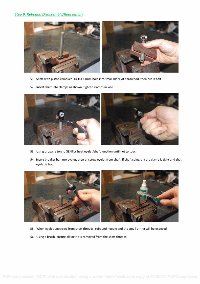
53. Using propane torch, GENTLY heat eyelet/shaft junction until hot to touch
54. Insert breaker bar into eyelet, then unscrew eyelet from shaft, if shaft spins, ensure clamp is tight and that eyelet is hot
55. When eyelet unscrews from shaft threads, rebound needle and the small o-‐ring will be exposed
56. Using a brush, ensure all loctite is removed from the shaft threads
PDF compression, OCR, web optimization using a watermarked evaluation copy of CVISION PDFCompressor

57. Press rebound needle out of shaft, replace small o-‐ring at threaded end of shaft
58. The rebound system has been fully disassembled
59. Clean all remaining loctite from eyelet threads with a brush
60. Unscrew rebound adjust from eyelet, being careful not to loose the detent ball or spring
61. Clean both adjuster and insides of the eyelet, regrease both, then reinsert the adjuster in eyelet
62. Clean and lightly grease rebound needle, then reinsert into the shaft, ensure that the small o-‐ring at
threaded end has properly engaged over the needle and that it is sitting flush in its small shaft recess
PDF compression, OCR, web optimization using a watermarked evaluation copy of CVISION PDFCompressor

63. Reinsert the shaft into the clamps, place a small amount of loctite on threads, ensure loctite does not spill into rebound needle or on shaft surface
64. Reinstall the eyelet onto the shaft, hand tighten, the ensure clamps are tight
65. Using breaker bar, retighten the eyelet, the clamps will needed to be significantly tight to ensure that
eyelet tightens properly
66. Remove shaft from the clamps and clamp the eyelets into the vice. Using a small Allen key, gently push down on the rebound needle so that it engages the adjuster
67. Using a syringe, inject suspension oil down into the rebound assembly to purge air, cover the rebound
hole if needed. The rebound assembly is now rebuilt.
PDF compression, OCR, web optimization using a watermarked evaluation copy of CVISION PDFCompressor

Step 10: Propedal Disassembly/ Reassembly
(Many thanks to Enemy1 for Pics and instructions)
68. To Access Propedal Spring and plate o-‐ring, with shock clamped upright in vice, remove the snap ring
using long nose circlip pliers
69. Replace o-‐ring, then reinstall spring back in reservoir, along with Propedal base plate, then reinstall circlip, insuring the it is properly seated in the recess. (Second Picture shows reservoir with Propedal
assembly removed
70. Unscrew black bottom out plunger from grey housing
71. Remove and replace o-‐ring, then reinstall black bottom out plunger in grey housing
PDF compression, OCR, web optimization using a watermarked evaluation copy of CVISION PDFCompressor

STEP 11: Replacing IFP and Bottom Out assembly o-‐rings, reassembling shaft assembly
72. Place a few drops of suspension fluid on a new IFP o-‐ring, and place it back on the IFP (In picture, new o-‐ring in place on IFP, old one next to IFP)
73. Place a few drops of suspension fluid on new bottom out housing and adjuster o-‐rings, then place them back on the assembly (the position of the old o-‐rings on the table is respective of where they go on
the BO assembly)
74. Wipe some suspension fluid on shaft, and replace rubber bottom out bumper
75. Reinsert the shaft seal housing back onto the shaft, be careful to put it on straight, take your time, DO
NOT FORCE IT, otherwise damage to the shaft or bushing may result
76. Replace the piston/shim assembly, and retighten. Just snug it tight, if you over tighten it too much, you may crush the shims and prevent them flexing
77. After you have retightened the piston, pull the shaft housing all the way up. Coat Piston and shim stack in oil, as to minimize air in shim, piston assembly. You have now successfully rebuild the shaft assembly
PDF compression, OCR, web optimization using a watermarked evaluation copy of CVISION PDFCompressor

STEP 12: Refilling oil and reinstalling shaft assembly
78. Refill the main chamber with oil
79. Let it filter into piggyback chamber and keep filling until piggyback chamber is almost overflowing
80. Place the IFP into the chamber, press it so it just sits on the top of the threads (ensure bleed screw is in)
81. Fill main chamber with suspension oil until it is almost overflowing
82. While holding IFP in place, reinsert the piston into the chamber and thread the seal housing on, hand
tighten it at this stage
83. Remove IFP bleed screw
PDF compression, OCR, web optimization using a watermarked evaluation copy of CVISION PDFCompressor

STEP 13: Reinserting IFP and reinstalling Bottom Out assembly
84. Depress IFP past threads, ensure bleed screw is removed, and wear safety glasses, as oil will squirt through bleed hole
85. Using you measuring tool, push IFP to its correct depth. If you did not record your IFP depth, use the depth chart at the end of this document. Tap body to displace any trapped air as your pushing the IFP
in, this will ensure a good bleed
86. Reinstall bleed screw, drain and wipe excess oil from IFP chamber
87. Using spanner or wrenches, retighten the shaft housing. Its recommended that you use the old tube to
protect the shaft
88. Reinsert the bottom out assembly
89. Using a spanner or wrench, tighten the grey cap
PDF compression, OCR, web optimization using a watermarked evaluation copy of CVISION PDFCompressor

STEP 14: Final Reassembly
90. Reinstall the Bottom Out adjuster cap
91. Tighten the 2 grub screws
92. Reinflate the boost valve to a minimum of 125PSI
93. Clean the shock over with Isopropyl Alcohol or a wet cloth
94. Reinstall spring, any reducers and valve cap (and in my case, my shock boot)
95. Reinstall the shock back onto your bike
96. Do the bounce test on your bike to lube internal parts, then set adjustments to you settings, bounce check again to make sure everything is working correctly
97. Success = BEER!
PDF compression, OCR, web optimization using a watermarked evaluation copy of CVISION PDFCompressor

IFP Depth Chart:
EYE to EYE – Stroke
Metric;
190mm, 50mm = 32mm
200mm, 50mm = 32mm
200mm, 57mm = 33mm
215mm, 64mm = 34mm
222mm, 64mm = 34mm
241mm, 76mm = 38mm
Imperial;
7.500, 2.00 = 1.25
7.875, 2.00 = 1.25
7.875, 2.25 = 1.30
8.500, 2.50 = 1.35
8.750, 2.50 = 1.35
9.500, 3.00 = 1.48
Thanks to EmanResu on MTBR for finding the IFP chart
Thanks to Enemy1 for Propedal instructions
PDF compression, OCR, web optimization using a watermarked evaluation copy of CVISION PDFCompressor

Acknowledgements
Big thanks to the people who contributed their valuable knowledge to help me compile this guide, id name you individually, but you know who you are!
Info obtained from people on:
-‐ MTBR
-‐ Pinkbike
-‐ ROTORBURN AUSTRALIA (formally FARKIN)
-‐ Ride Monkey
Compiled By me, Nick_M2R on 18th May 2009
Updated: 28th January 2010
While I have proof read this guide carefully, but I’m only human. If you have notice any mistakes or have any improvements, PM me on MTBR and ill include them in future releases.
Enjoy Guys and Girls!
Version: 4
PDF compression, OCR, web optimization using a watermarked evaluation copy of CVISION PDFCompressor
Top Related