


Languages
Pages
Legal


Vehicle Communication Software
Operator’s Manual
February 2009
ZEESCGB234A Rev. T
Disclaimer of Warranties and Limitations of LiabilitiesWhile the authors have taken due care in the preparation of this manual, nothing contained herein:
• modifies or alters in any way the standard terms and conditions of the purchase, lease or rental agreement under the terms of which the equipment to which this manual relates was acquired,
• increases in any way the liability to the customer or to third parties.
To the ReaderWhile every effort has been made to ensure that the information contained in this manual is correct, complete and up-to date, the right to change any part of this document at any time without prior notice is reserved.
Warning:Warning:ä Before installing, maintaining or operating this unit, please read
this manual carefully, paying extra attention to the safety warnings and precautions.
Copyright 2009 Snap-on UK Holdings Ltd.All Rights Reserved
Snap-on DiagnosticsUnit 1B, Boland Industrial EstateMallow RoadCorkIrelandTel: +353.21.4211600Fax: +353.21.4211601
Web-sites:http://www.sun-diagnostics.com/http://www.snapon.com/

Vehicle Communication Software 2009-02
Trademark InformationSCANBAY II™, Scanner™, Scan Gra-Fix, Scan-Link, ScanView, TechWare, MODIS™, SOLUS™, Sun and Snap-on are trademarks of Snap-on Incorporated, registered in the United States and in other countries. All other marks, logos or names are the property of their respective owners.
i
Table of Contents
Table of Contents . . . . . . . . . . . . . . . . . . . . . . . . . . . . . . i
1 Vehicle Communication Software . . . . . . . . . . . . . . . . .11.1 Vehicle Communication Software . . . . . . . . . . . . . . . . . . . . . . . . . . . 11.2 Adaptors Overview & Data Parameters . . . . . . . . . . . . . . . . . . . . . . . 11.3 Related Manuals . . . . . . . . . . . . . . . . . . . . . . . . . . . . . . . . . . . . . . . . 1
2 Alfa Romeo/Fiat/Lancia . . . . . . . . . . . . . . . . . . . . . . . . . .3Overview . . . . . . . . . . . . . . . . . . . . . . . . . . . . . . . . . . . . . . . . . . . . . . . 3
2.1 Start-up Sequence . . . . . . . . . . . . . . . . . . . . . . . . . . . . . . . . . . . . . . . 42.2 Identify Vehicle . . . . . . . . . . . . . . . . . . . . . . . . . . . . . . . . . . . . . . . . . . 5
2.2.1 Vehicle Selection Tips . . . . . . . . . . . . . . . . . . . . . . . . . . . . . 52.2.2 System ID Mode . . . . . . . . . . . . . . . . . . . . . . . . . . . . . . . . . . 5
2.3 Select System to be Tested . . . . . . . . . . . . . . . . . . . . . . . . . . . . . . . . 62.3.1 System List . . . . . . . . . . . . . . . . . . . . . . . . . . . . . . . . . . . . . . 62.3.2 Additional Notes . . . . . . . . . . . . . . . . . . . . . . . . . . . . . . . . . . 7
2.4 Connect Scanner . . . . . . . . . . . . . . . . . . . . . . . . . . . . . . . . . . . . . . . . 72.5 Main Menu . . . . . . . . . . . . . . . . . . . . . . . . . . . . . . . . . . . . . . . . . . . . . 72.6 Codes & Data . . . . . . . . . . . . . . . . . . . . . . . . . . . . . . . . . . . . . . . . . . . 8
2.6.1 Codes & Data “Exit Menu” . . . . . . . . . . . . . . . . . . . . . . . . . . 82.7 Review Movie . . . . . . . . . . . . . . . . . . . . . . . . . . . . . . . . . . . . . . . . . . . 9
2.7.1 Review Move “Exit” Menu . . . . . . . . . . . . . . . . . . . . . . . . . . 92.8 Functional Tests . . . . . . . . . . . . . . . . . . . . . . . . . . . . . . . . . . . . . . . . 102.9 Stop Communication, (Other Systems) . . . . . . . . . . . . . . . . . . . . . . 11
2.10 Custom Setup . . . . . . . . . . . . . . . . . . . . . . . . . . . . . . . . . . . . . . . . . 11
3 BMW . . . . . . . . . . . . . . . . . . . . . . . . . . . . . . . . . . . . . . . .13Overview . . . . . . . . . . . . . . . . . . . . . . . . . . . . . . . . . . . . . . . . . . . . . . 13
3.1 Start-up Sequence . . . . . . . . . . . . . . . . . . . . . . . . . . . . . . . . . . . . . . 143.2 Identify Vehicle . . . . . . . . . . . . . . . . . . . . . . . . . . . . . . . . . . . . . . . . . 15
3.2.1 System ID Mode . . . . . . . . . . . . . . . . . . . . . . . . . . . . . . . . . 15
ii Vehicle Communication Software 2009-02
TABLE OF CONTENTS
3.3 Select System to be Tested . . . . . . . . . . . . . . . . . . . . . . . . . . . . . . .163.3.1 System List . . . . . . . . . . . . . . . . . . . . . . . . . . . . . . . . . . . . .163.3.2 Additional Notes: . . . . . . . . . . . . . . . . . . . . . . . . . . . . . . . . .17
3.4 Connect Scanner . . . . . . . . . . . . . . . . . . . . . . . . . . . . . . . . . . . . . . .183.5 Main Menu . . . . . . . . . . . . . . . . . . . . . . . . . . . . . . . . . . . . . . . . . . . .193.6 Codes & Data . . . . . . . . . . . . . . . . . . . . . . . . . . . . . . . . . . . . . . . . . .19
3.6.1 Codes & Data “Exit” Menu . . . . . . . . . . . . . . . . . . . . . . . . .203.6.1.1 Notes to Clear Codes . . . . . . . . . . . . . . . . . . . . . .20
3.7 Review Movie . . . . . . . . . . . . . . . . . . . . . . . . . . . . . . . . . . . . . . . . . .213.7.1 Review Movie “Exit” Menu . . . . . . . . . . . . . . . . . . . . . . . . .21
3.8 Functional Tests . . . . . . . . . . . . . . . . . . . . . . . . . . . . . . . . . . . . . . . .223.8.1 BMW Engines, Actuator Tests Notes: . . . . . . . . . . . . . . . . .233.8.2 Reset Service Lamps, Notes: . . . . . . . . . . . . . . . . . . . . . . .233.8.3 Special Functions, (Sub-menu), Example . . . . . . . . . . . . . .23
3.9 Stop Communication, (Other Systems) . . . . . . . . . . . . . . . . . . . . . .243.10 Custom Setup . . . . . . . . . . . . . . . . . . . . . . . . . . . . . . . . . . . . . . . . . .25
4 Citroën . . . . . . . . . . . . . . . . . . . . . . . . . . . . . . . . . . . . . .27Overview . . . . . . . . . . . . . . . . . . . . . . . . . . . . . . . . . . . . . . . . . . . . . .27
4.1 Start-up Sequence . . . . . . . . . . . . . . . . . . . . . . . . . . . . . . . . . . . . . .284.2 Identify Vehicle . . . . . . . . . . . . . . . . . . . . . . . . . . . . . . . . . . . . . . . . .29
4.2.1 Vehicle Selection Tips . . . . . . . . . . . . . . . . . . . . . . . . . . . . .294.2.2 System ID Mode . . . . . . . . . . . . . . . . . . . . . . . . . . . . . . . . .30
4.3 Select System to be Tested . . . . . . . . . . . . . . . . . . . . . . . . . . . . . . .314.3.1 System List . . . . . . . . . . . . . . . . . . . . . . . . . . . . . . . . . . . . .314.3.2 Additional Notes . . . . . . . . . . . . . . . . . . . . . . . . . . . . . . . . .31
4.4 Connect Scanner . . . . . . . . . . . . . . . . . . . . . . . . . . . . . . . . . . . . . . .324.5 Main Menu . . . . . . . . . . . . . . . . . . . . . . . . . . . . . . . . . . . . . . . . . . . .334.6 Codes & Data . . . . . . . . . . . . . . . . . . . . . . . . . . . . . . . . . . . . . . . . . .33
4.6.1 Codes & Data “Exit” menu . . . . . . . . . . . . . . . . . . . . . . . . .344.6.1.1 Notes to Clear ECU Codes . . . . . . . . . . . . . . . . . .34
4.7 Review Movie . . . . . . . . . . . . . . . . . . . . . . . . . . . . . . . . . . . . . . . . . .354.7.1 Review Movie “Exit” Menu . . . . . . . . . . . . . . . . . . . . . . . . .35
4.8 Functional Tests . . . . . . . . . . . . . . . . . . . . . . . . . . . . . . . . . . . . . . . .364.9 Stop Communication, (Other Systems) . . . . . . . . . . . . . . . . . . . . . .38
4.10 Custom Setup . . . . . . . . . . . . . . . . . . . . . . . . . . . . . . . . . . . . . . . . . .39
5 Ford . . . . . . . . . . . . . . . . . . . . . . . . . . . . . . . . . . . . . . . .41Overview . . . . . . . . . . . . . . . . . . . . . . . . . . . . . . . . . . . . . . . . . . . . . .41
iii
5.1 Start-up Sequence . . . . . . . . . . . . . . . . . . . . . . . . . . . . . . . . . . . . . . 425.2 Identify Vehicle . . . . . . . . . . . . . . . . . . . . . . . . . . . . . . . . . . . . . . . . . 435.3 Connect Scanner . . . . . . . . . . . . . . . . . . . . . . . . . . . . . . . . . . . . . . . 445.4 Select/Detect System to be Tested . . . . . . . . . . . . . . . . . . . . . . . . . 45
5.4.1 System List . . . . . . . . . . . . . . . . . . . . . . . . . . . . . . . . . . . . . 455.4.2 CAN Systems Notes . . . . . . . . . . . . . . . . . . . . . . . . . . . . . 465.4.3 System ID Mode . . . . . . . . . . . . . . . . . . . . . . . . . . . . . . . . . 46
5.5 Main Menu . . . . . . . . . . . . . . . . . . . . . . . . . . . . . . . . . . . . . . . . . . . . 475.5.1 Main Menu Selections . . . . . . . . . . . . . . . . . . . . . . . . . . . . 47
5.6 Data (No Codes) . . . . . . . . . . . . . . . . . . . . . . . . . . . . . . . . . . . . . . . 485.6.1 Data Sub-menu . . . . . . . . . . . . . . . . . . . . . . . . . . . . . . . . . 485.6.2 Data (No Codes) “Exit” Menu . . . . . . . . . . . . . . . . . . . . . . . 49
5.7 Ford Service Codes . . . . . . . . . . . . . . . . . . . . . . . . . . . . . . . . . . . . . 495.8 Review Movie . . . . . . . . . . . . . . . . . . . . . . . . . . . . . . . . . . . . . . . . . . 53
5.8.1 Review Movie “Exit” Menu . . . . . . . . . . . . . . . . . . . . . . . . . 535.9 Functional Tests . . . . . . . . . . . . . . . . . . . . . . . . . . . . . . . . . . . . . . . . 54
5.9.1 Functional Tests — EEC-IV . . . . . . . . . . . . . . . . . . . . . . . . 545.9.2 Functional Tests — EEC-V . . . . . . . . . . . . . . . . . . . . . . . . . 55
5.10 Other Systems . . . . . . . . . . . . . . . . . . . . . . . . . . . . . . . . . . . . . . . . . 565.10.1 Super Star II Selection . . . . . . . . . . . . . . . . . . . . . . . . . . . . 57
5.11 Custom Setup . . . . . . . . . . . . . . . . . . . . . . . . . . . . . . . . . . . . . . . . . 585.12 Special Ford Galaxy Systems . . . . . . . . . . . . . . . . . . . . . . . . . . . . . 58
5.12.1 System Identification . . . . . . . . . . . . . . . . . . . . . . . . . . . . . 585.12.2 Select System to be Tested . . . . . . . . . . . . . . . . . . . . . . . . 595.12.3 Main Menu, “Engine Management” . . . . . . . . . . . . . . . . . . 59
6 Honda . . . . . . . . . . . . . . . . . . . . . . . . . . . . . . . . . . . . . . .61Overview . . . . . . . . . . . . . . . . . . . . . . . . . . . . . . . . . . . . . . . . . . . . . . 61
6.1 Start-up Sequence . . . . . . . . . . . . . . . . . . . . . . . . . . . . . . . . . . . . . . 626.2 Identify Vehicle . . . . . . . . . . . . . . . . . . . . . . . . . . . . . . . . . . . . . . . . . 626.3 Select System to be Tested . . . . . . . . . . . . . . . . . . . . . . . . . . . . . . . 63
6.3.1 System List . . . . . . . . . . . . . . . . . . . . . . . . . . . . . . . . . . . . . 636.4 Connect Scanner . . . . . . . . . . . . . . . . . . . . . . . . . . . . . . . . . . . . . . . 636.5 Main Menu . . . . . . . . . . . . . . . . . . . . . . . . . . . . . . . . . . . . . . . . . . . . 646.6 Codes & Data Menu . . . . . . . . . . . . . . . . . . . . . . . . . . . . . . . . . . . . . 65
6.6.1 Data (No Codes) . . . . . . . . . . . . . . . . . . . . . . . . . . . . . . . . 656.6.2 Data (No Codes) “Exit” Menu . . . . . . . . . . . . . . . . . . . . . . . 666.6.3 Codes Menu . . . . . . . . . . . . . . . . . . . . . . . . . . . . . . . . . . . . 666.6.4 Codes “Exit” Menu . . . . . . . . . . . . . . . . . . . . . . . . . . . . . . . 676.6.5 Clear Codes . . . . . . . . . . . . . . . . . . . . . . . . . . . . . . . . . . . . 67

iv Vehicle Communication Software 2009-02
TABLE OF CONTENTS
6.7 Movies . . . . . . . . . . . . . . . . . . . . . . . . . . . . . . . . . . . . . . . . . . . . . . .686.7.1 Print/Review Movies “Exit” Menu . . . . . . . . . . . . . . . . . . . .68
6.8 Custom Setup . . . . . . . . . . . . . . . . . . . . . . . . . . . . . . . . . . . . . . . . . .696.9 Anti-lock Brakes Systems . . . . . . . . . . . . . . . . . . . . . . . . . . . . . . . . .69
6.10 Airbag Systems . . . . . . . . . . . . . . . . . . . . . . . . . . . . . . . . . . . . . . . . .69
7 Land Rover . . . . . . . . . . . . . . . . . . . . . . . . . . . . . . . . . . .71Overview . . . . . . . . . . . . . . . . . . . . . . . . . . . . . . . . . . . . . . . . . . . . . .71
7.1 Start-up Sequence . . . . . . . . . . . . . . . . . . . . . . . . . . . . . . . . . . . . . .727.2 Identify Vehicle . . . . . . . . . . . . . . . . . . . . . . . . . . . . . . . . . . . . . . . . .73
7.2.1 System ID Mode, (Expert Mode) . . . . . . . . . . . . . . . . . . . . .737.3 Select System to be Tested . . . . . . . . . . . . . . . . . . . . . . . . . . . . . . .74
7.3.1 System List . . . . . . . . . . . . . . . . . . . . . . . . . . . . . . . . . . . . .747.3.2 Additional Notes: . . . . . . . . . . . . . . . . . . . . . . . . . . . . . . . . .74
7.4 Connect Scanner . . . . . . . . . . . . . . . . . . . . . . . . . . . . . . . . . . . . . . .757.5 Main Menu . . . . . . . . . . . . . . . . . . . . . . . . . . . . . . . . . . . . . . . . . . . .757.6 Codes & Data . . . . . . . . . . . . . . . . . . . . . . . . . . . . . . . . . . . . . . . . . .76
7.6.1 Data (No Codes) . . . . . . . . . . . . . . . . . . . . . . . . . . . . . . . . .767.6.2 Codes Only . . . . . . . . . . . . . . . . . . . . . . . . . . . . . . . . . . . . .767.6.3 Codes & Data “Exit” Menu . . . . . . . . . . . . . . . . . . . . . . . . .77
7.7 Review Movie . . . . . . . . . . . . . . . . . . . . . . . . . . . . . . . . . . . . . . . . . .777.7.1 Review Movie “Exit” Menu . . . . . . . . . . . . . . . . . . . . . . . . .78
7.8 Functional Tests . . . . . . . . . . . . . . . . . . . . . . . . . . . . . . . . . . . . . . . .787.9 Stop Communication, (Other Systems) . . . . . . . . . . . . . . . . . . . . . .79
7.10 Custom Setup . . . . . . . . . . . . . . . . . . . . . . . . . . . . . . . . . . . . . . . . . .80
8 Mercedes . . . . . . . . . . . . . . . . . . . . . . . . . . . . . . . . . . . .81Overview . . . . . . . . . . . . . . . . . . . . . . . . . . . . . . . . . . . . . . . . . . . . . .81
8.1 Start-up Sequence . . . . . . . . . . . . . . . . . . . . . . . . . . . . . . . . . . . . . .828.2 Identify Vehicle . . . . . . . . . . . . . . . . . . . . . . . . . . . . . . . . . . . . . . . . .83
8.2.1 System ID Mode . . . . . . . . . . . . . . . . . . . . . . . . . . . . . . . . .848.3 Select System to be Tested . . . . . . . . . . . . . . . . . . . . . . . . . . . . . . .858.4 Connect Scanner . . . . . . . . . . . . . . . . . . . . . . . . . . . . . . . . . . . . . . .858.5 Main Menu . . . . . . . . . . . . . . . . . . . . . . . . . . . . . . . . . . . . . . . . . . . .868.6 Data . . . . . . . . . . . . . . . . . . . . . . . . . . . . . . . . . . . . . . . . . . . . . . . . .87
8.6.1 Data Sub-Menu . . . . . . . . . . . . . . . . . . . . . . . . . . . . . . . . . .878.6.2 Data “Exit” Menu . . . . . . . . . . . . . . . . . . . . . . . . . . . . . . . . .88

v
8.7 Codes . . . . . . . . . . . . . . . . . . . . . . . . . . . . . . . . . . . . . . . . . . . . . . . . 898.7.1 Display Codes . . . . . . . . . . . . . . . . . . . . . . . . . . . . . . . . . . 898.7.2 Codes “Exit” Menu . . . . . . . . . . . . . . . . . . . . . . . . . . . . . . . 90
8.8 Review Movie . . . . . . . . . . . . . . . . . . . . . . . . . . . . . . . . . . . . . . . . . . 908.8.1 Review Movie “Exit” Menu . . . . . . . . . . . . . . . . . . . . . . . . . 91
8.9 Functional Tests . . . . . . . . . . . . . . . . . . . . . . . . . . . . . . . . . . . . . . . . 918.10 Stop Communication, (Other Systems) . . . . . . . . . . . . . . . . . . . . . . 938.11 Custom Setup . . . . . . . . . . . . . . . . . . . . . . . . . . . . . . . . . . . . . . . . . 94
9 MG/Rover . . . . . . . . . . . . . . . . . . . . . . . . . . . . . . . . . . . .95Overview . . . . . . . . . . . . . . . . . . . . . . . . . . . . . . . . . . . . . . . . . . . . . . 95
9.1 Start-up Sequence . . . . . . . . . . . . . . . . . . . . . . . . . . . . . . . . . . . . . . 969.2 Identify Vehicle . . . . . . . . . . . . . . . . . . . . . . . . . . . . . . . . . . . . . . . . . 97
9.2.1 System ID Mode, (Expert Mode) . . . . . . . . . . . . . . . . . . . . 979.3 Select System to be Tested . . . . . . . . . . . . . . . . . . . . . . . . . . . . . . . 98
9.3.1 System List . . . . . . . . . . . . . . . . . . . . . . . . . . . . . . . . . . . . . 989.3.2 Additional Notes: . . . . . . . . . . . . . . . . . . . . . . . . . . . . . . . . 98
9.4 Connect Scanner . . . . . . . . . . . . . . . . . . . . . . . . . . . . . . . . . . . . . . . 989.5 Main Menu . . . . . . . . . . . . . . . . . . . . . . . . . . . . . . . . . . . . . . . . . . . . 999.6 Codes & Data . . . . . . . . . . . . . . . . . . . . . . . . . . . . . . . . . . . . . . . . . . 99
9.6.1 Data (No Codes) . . . . . . . . . . . . . . . . . . . . . . . . . . . . . . . 1009.6.2 Codes Only . . . . . . . . . . . . . . . . . . . . . . . . . . . . . . . . . . . 1009.6.3 Codes & Data “Exit” Menu . . . . . . . . . . . . . . . . . . . . . . . . 100
9.7 Review Movie . . . . . . . . . . . . . . . . . . . . . . . . . . . . . . . . . . . . . . . . . 1019.7.1 Review Movie “Exit” Menu . . . . . . . . . . . . . . . . . . . . . . . . 101
9.8 Functional Tests . . . . . . . . . . . . . . . . . . . . . . . . . . . . . . . . . . . . . . . 1029.9 Stop Communication, (Other Systems) . . . . . . . . . . . . . . . . . . . . . 103
9.10 Custom Setup . . . . . . . . . . . . . . . . . . . . . . . . . . . . . . . . . . . . . . . . 104
10 Nissan . . . . . . . . . . . . . . . . . . . . . . . . . . . . . . . . . . . . . .105Overview . . . . . . . . . . . . . . . . . . . . . . . . . . . . . . . . . . . . . . . . . . . . . 105
10.1 Start-up Sequence . . . . . . . . . . . . . . . . . . . . . . . . . . . . . . . . . . . . . 10610.2 Identify Vehicle . . . . . . . . . . . . . . . . . . . . . . . . . . . . . . . . . . . . . . . . 10610.3 Select System to be Tested . . . . . . . . . . . . . . . . . . . . . . . . . . . . . . 107
10.3.1 System List . . . . . . . . . . . . . . . . . . . . . . . . . . . . . . . . . . . . 10710.4 Connect Scanner . . . . . . . . . . . . . . . . . . . . . . . . . . . . . . . . . . . . . . 10710.5 Main Menu . . . . . . . . . . . . . . . . . . . . . . . . . . . . . . . . . . . . . . . . . . . 108
vi Vehicle Communication Software 2009-02
TABLE OF CONTENTS
10.6 Codes & Data Menu . . . . . . . . . . . . . . . . . . . . . . . . . . . . . . . . . . . .10810.6.1 Data (No Codes) . . . . . . . . . . . . . . . . . . . . . . . . . . . . . . . .10910.6.2 Data (No Codes) “Exit” Menu . . . . . . . . . . . . . . . . . . . . . .10910.6.3 Codes Only . . . . . . . . . . . . . . . . . . . . . . . . . . . . . . . . . . . .10910.6.4 Codes Only “Exit” Menu . . . . . . . . . . . . . . . . . . . . . . . . . .11010.6.5 Clear Codes . . . . . . . . . . . . . . . . . . . . . . . . . . . . . . . . . . .110
10.7 Movies . . . . . . . . . . . . . . . . . . . . . . . . . . . . . . . . . . . . . . . . . . . . . .11010.7.1 Print/Review Movie “Exit” Menu . . . . . . . . . . . . . . . . . . . . 111
10.8 Custom Setup . . . . . . . . . . . . . . . . . . . . . . . . . . . . . . . . . . . . . . . . . 11110.9 Actuator Tests . . . . . . . . . . . . . . . . . . . . . . . . . . . . . . . . . . . . . . . . .112
11 Opel/Vauxhall . . . . . . . . . . . . . . . . . . . . . . . . . . . . . . . . 113Overview . . . . . . . . . . . . . . . . . . . . . . . . . . . . . . . . . . . . . . . . . . . . .113
11.1 Start-up Sequence . . . . . . . . . . . . . . . . . . . . . . . . . . . . . . . . . . . . .11411.2 Identify Vehicle . . . . . . . . . . . . . . . . . . . . . . . . . . . . . . . . . . . . . . . .115
11.2.1 Vehicle Selection Tips . . . . . . . . . . . . . . . . . . . . . . . . . . . .11511.2.2 System ID Mode, (Expert Mode) . . . . . . . . . . . . . . . . . . . .116
11.3 Select System to be Tested . . . . . . . . . . . . . . . . . . . . . . . . . . . . . .11611.3.1 System List . . . . . . . . . . . . . . . . . . . . . . . . . . . . . . . . . . . .11711.3.2 Additional Notes: . . . . . . . . . . . . . . . . . . . . . . . . . . . . . . . .117
11.4 Connect Scanner . . . . . . . . . . . . . . . . . . . . . . . . . . . . . . . . . . . . . .11711.5 Main Menu . . . . . . . . . . . . . . . . . . . . . . . . . . . . . . . . . . . . . . . . . . .11811.6 Codes & Data . . . . . . . . . . . . . . . . . . . . . . . . . . . . . . . . . . . . . . . . .118
11.6.1 Data (No Codes) . . . . . . . . . . . . . . . . . . . . . . . . . . . . . . . .11911.6.2 Codes Only . . . . . . . . . . . . . . . . . . . . . . . . . . . . . . . . . . . .11911.6.3 Codes & Data Exit Menu . . . . . . . . . . . . . . . . . . . . . . . . . .119
11.7 Review Movie . . . . . . . . . . . . . . . . . . . . . . . . . . . . . . . . . . . . . . . . .12011.7.1 Review Movie “Exit” Menu . . . . . . . . . . . . . . . . . . . . . . . .120
11.8 Functional Tests . . . . . . . . . . . . . . . . . . . . . . . . . . . . . . . . . . . . . . .12111.9 Stop Communication, (Other Systems) . . . . . . . . . . . . . . . . . . . . .122
11.10 Custom Setup . . . . . . . . . . . . . . . . . . . . . . . . . . . . . . . . . . . . . . . . .123
12 Peugeot . . . . . . . . . . . . . . . . . . . . . . . . . . . . . . . . . . . .125Overview . . . . . . . . . . . . . . . . . . . . . . . . . . . . . . . . . . . . . . . . . . . . .125
12.1 Start-up Sequence . . . . . . . . . . . . . . . . . . . . . . . . . . . . . . . . . . . . .12612.2 Identify Vehicle . . . . . . . . . . . . . . . . . . . . . . . . . . . . . . . . . . . . . . . .127
12.2.1 Vehicle Selection Tips . . . . . . . . . . . . . . . . . . . . . . . . . . . .12712.2.2 System ID Mode . . . . . . . . . . . . . . . . . . . . . . . . . . . . . . . .128
vii
12.3 Select System to be Tested . . . . . . . . . . . . . . . . . . . . . . . . . . . . . . 12912.3.1 System List . . . . . . . . . . . . . . . . . . . . . . . . . . . . . . . . . . . . 12912.3.2 Additional Notes: . . . . . . . . . . . . . . . . . . . . . . . . . . . . . . . 130
12.4 Connect Scanner . . . . . . . . . . . . . . . . . . . . . . . . . . . . . . . . . . . . . . 13112.5 Main Menu . . . . . . . . . . . . . . . . . . . . . . . . . . . . . . . . . . . . . . . . . . . 13112.6 Codes & Data . . . . . . . . . . . . . . . . . . . . . . . . . . . . . . . . . . . . . . . . . 132
12.6.1 Codes & Data “Exit” Menu . . . . . . . . . . . . . . . . . . . . . . . . 13212.7 Review Movie . . . . . . . . . . . . . . . . . . . . . . . . . . . . . . . . . . . . . . . . . 133
12.7.1 Review Movie “Exit” Menu . . . . . . . . . . . . . . . . . . . . . . . . 13312.8 Functional Tests . . . . . . . . . . . . . . . . . . . . . . . . . . . . . . . . . . . . . . . 13412.9 Stop Communication, (Other Systems) . . . . . . . . . . . . . . . . . . . . . 136
12.10 Custom Setup . . . . . . . . . . . . . . . . . . . . . . . . . . . . . . . . . . . . . . . . 137
13 Renault . . . . . . . . . . . . . . . . . . . . . . . . . . . . . . . . . . . . .139Overview . . . . . . . . . . . . . . . . . . . . . . . . . . . . . . . . . . . . . . . . . . . . . 139
13.1 Start-up Sequence . . . . . . . . . . . . . . . . . . . . . . . . . . . . . . . . . . . . . 14013.2 Identify Vehicle . . . . . . . . . . . . . . . . . . . . . . . . . . . . . . . . . . . . . . . . 141
13.2.1 Vehicle Selection Notes . . . . . . . . . . . . . . . . . . . . . . . . . . 14113.2.2 System ID Mode . . . . . . . . . . . . . . . . . . . . . . . . . . . . . . . . 141
13.3 Select System to be Tested . . . . . . . . . . . . . . . . . . . . . . . . . . . . . . 14213.3.1 System List . . . . . . . . . . . . . . . . . . . . . . . . . . . . . . . . . . . . 142
13.4 Connect Scanner . . . . . . . . . . . . . . . . . . . . . . . . . . . . . . . . . . . . . . 14213.5 Main Menu . . . . . . . . . . . . . . . . . . . . . . . . . . . . . . . . . . . . . . . . . . . 14313.6 Codes & Data . . . . . . . . . . . . . . . . . . . . . . . . . . . . . . . . . . . . . . . . . 143
13.6.1 Data (No Codes) . . . . . . . . . . . . . . . . . . . . . . . . . . . . . . . 14413.6.2 Codes Only . . . . . . . . . . . . . . . . . . . . . . . . . . . . . . . . . . . 14413.6.3 Codes & Data “Exit” Menu . . . . . . . . . . . . . . . . . . . . . . . . 144
13.7 Review Movie . . . . . . . . . . . . . . . . . . . . . . . . . . . . . . . . . . . . . . . . . 14513.7.1 Review Movie “Exit” Menu . . . . . . . . . . . . . . . . . . . . . . . . 145
13.8 Functional Tests . . . . . . . . . . . . . . . . . . . . . . . . . . . . . . . . . . . . . . . 14613.9 End Diagnosis, (Other Systems) . . . . . . . . . . . . . . . . . . . . . . . . . . 147
13.10 Custom Setup . . . . . . . . . . . . . . . . . . . . . . . . . . . . . . . . . . . . . . . . 14813.11 Additional Code Information . . . . . . . . . . . . . . . . . . . . . . . . . . . . . . 148
14 Toyota . . . . . . . . . . . . . . . . . . . . . . . . . . . . . . . . . . . . . .149Overview . . . . . . . . . . . . . . . . . . . . . . . . . . . . . . . . . . . . . . . . . . . . . 149
14.1 Start-up Sequence . . . . . . . . . . . . . . . . . . . . . . . . . . . . . . . . . . . . . 15014.2 Identify Vehicle . . . . . . . . . . . . . . . . . . . . . . . . . . . . . . . . . . . . . . . . 150

viii Vehicle Communication Software 2009-02
TABLE OF CONTENTS
14.3 Select System to be Tested . . . . . . . . . . . . . . . . . . . . . . . . . . . . . .15114.3.1 System List . . . . . . . . . . . . . . . . . . . . . . . . . . . . . . . . . . . .151
14.4 Connect Scanner . . . . . . . . . . . . . . . . . . . . . . . . . . . . . . . . . . . . . .15114.5 Main Menu . . . . . . . . . . . . . . . . . . . . . . . . . . . . . . . . . . . . . . . . . . .15214.6 Codes & Data Menu . . . . . . . . . . . . . . . . . . . . . . . . . . . . . . . . . . . .153
14.6.1 Data (No Codes) . . . . . . . . . . . . . . . . . . . . . . . . . . . . . . . .15314.6.2 Data (No Codes) “Exit” Menu . . . . . . . . . . . . . . . . . . . . . .15414.6.3 Codes Only . . . . . . . . . . . . . . . . . . . . . . . . . . . . . . . . . . . .15414.6.4 Codes Only “Exit” Menu . . . . . . . . . . . . . . . . . . . . . . . . . .15514.6.5 Check Mode . . . . . . . . . . . . . . . . . . . . . . . . . . . . . . . . . . .15514.6.6 Check Mode “Exit” Menu . . . . . . . . . . . . . . . . . . . . . . . . .15614.6.7 Clear Codes . . . . . . . . . . . . . . . . . . . . . . . . . . . . . . . . . . .156
14.7 Movies . . . . . . . . . . . . . . . . . . . . . . . . . . . . . . . . . . . . . . . . . . . . . .15614.7.1 Print/Review Movie “Exit” Menu . . . . . . . . . . . . . . . . . . . .157
14.8 Custom Setup . . . . . . . . . . . . . . . . . . . . . . . . . . . . . . . . . . . . . . . . .15714.9 Actuator Tests . . . . . . . . . . . . . . . . . . . . . . . . . . . . . . . . . . . . . . . . .158
14.10 Anti-lock Brakes Systems . . . . . . . . . . . . . . . . . . . . . . . . . . . . . . . .158
15 VAG . . . . . . . . . . . . . . . . . . . . . . . . . . . . . . . . . . . . . . . .161Overview . . . . . . . . . . . . . . . . . . . . . . . . . . . . . . . . . . . . . . . . . . . . .161
15.1 Start-up Sequence . . . . . . . . . . . . . . . . . . . . . . . . . . . . . . . . . . . . .16215.2 Identify Vehicle . . . . . . . . . . . . . . . . . . . . . . . . . . . . . . . . . . . . . . . .163
15.2.1 System ID Mode . . . . . . . . . . . . . . . . . . . . . . . . . . . . . . . .16415.3 Connect Scanner . . . . . . . . . . . . . . . . . . . . . . . . . . . . . . . . . . . . . .16415.4 Select System to be Tested . . . . . . . . . . . . . . . . . . . . . . . . . . . . . .16515.5 Main Menu . . . . . . . . . . . . . . . . . . . . . . . . . . . . . . . . . . . . . . . . . . .166
15.5.1 Data (Sub-menu) . . . . . . . . . . . . . . . . . . . . . . . . . . . . . . .16715.6 Codes . . . . . . . . . . . . . . . . . . . . . . . . . . . . . . . . . . . . . . . . . . . . . . .167
15.6.1 Display Codes . . . . . . . . . . . . . . . . . . . . . . . . . . . . . . . . . .16715.6.2 Codes “Exit” Menu . . . . . . . . . . . . . . . . . . . . . . . . . . . . . .167
15.7 Data . . . . . . . . . . . . . . . . . . . . . . . . . . . . . . . . . . . . . . . . . . . . . . . .16815.7.1 Data Groups . . . . . . . . . . . . . . . . . . . . . . . . . . . . . . . . . . .169
15.7.1.1 Data Groups “Exit” Menu . . . . . . . . . . . . . . . . . .16915.7.2 Codes & Data . . . . . . . . . . . . . . . . . . . . . . . . . . . . . . . . . .169
15.7.2.1 Codes & Data “Exit” Menu . . . . . . . . . . . . . . . . .17015.8 Review Movie . . . . . . . . . . . . . . . . . . . . . . . . . . . . . . . . . . . . . . . . .170
15.8.1 Review Movie “Exit” Menu . . . . . . . . . . . . . . . . . . . . . . . .171
ix
15.9 Functional Tests . . . . . . . . . . . . . . . . . . . . . . . . . . . . . . . . . . . . . . . 17115.9.1 Functional Tests Menu . . . . . . . . . . . . . . . . . . . . . . . . . . . 171
15.9.1.1 Initiate Actuator Tests . . . . . . . . . . . . . . . . . . . . . 17115.9.1.2 Basic Setting: . . . . . . . . . . . . . . . . . . . . . . . . . . . 17215.9.1.3 Selection Towing Hook: . . . . . . . . . . . . . . . . . . . 17415.9.1.4 Service Interval Reset: . . . . . . . . . . . . . . . . . . . . 17415.9.1.5 Electronic Instrument Panel Types . . . . . . . . . . . 176
15.10 Stop Communication, (Other Systems) . . . . . . . . . . . . . . . . . . . . . 18215.11 Custom Setup . . . . . . . . . . . . . . . . . . . . . . . . . . . . . . . . . . . . . . . . 18315.12 Expert Mode . . . . . . . . . . . . . . . . . . . . . . . . . . . . . . . . . . . . . . . . . . 183
15.12.1 Automatic System Test: . . . . . . . . . . . . . . . . . . . . . . . . . . 18415.12.2 Blink Codes System: . . . . . . . . . . . . . . . . . . . . . . . . . . . . 18415.12.3 All Other Systems: . . . . . . . . . . . . . . . . . . . . . . . . . . . . . . 184
16 Volvo . . . . . . . . . . . . . . . . . . . . . . . . . . . . . . . . . . . . . . .189Overview . . . . . . . . . . . . . . . . . . . . . . . . . . . . . . . . . . . . . . . . . . . . . 189
16.1 Start-up Sequence . . . . . . . . . . . . . . . . . . . . . . . . . . . . . . . . . . . . . 19016.1.1 System ID Mode . . . . . . . . . . . . . . . . . . . . . . . . . . . . . . . . 190
16.2 Identify Vehicle . . . . . . . . . . . . . . . . . . . . . . . . . . . . . . . . . . . . . . . . 19116.3 Select System to be Tested . . . . . . . . . . . . . . . . . . . . . . . . . . . . . . 191
16.3.1 System List . . . . . . . . . . . . . . . . . . . . . . . . . . . . . . . . . . . . 19216.4 Connect Scanner . . . . . . . . . . . . . . . . . . . . . . . . . . . . . . . . . . . . . . 19216.5 Main Menu . . . . . . . . . . . . . . . . . . . . . . . . . . . . . . . . . . . . . . . . . . . 19316.6 Codes Only Menu . . . . . . . . . . . . . . . . . . . . . . . . . . . . . . . . . . . . . 194
16.6.1 Codes “Exit” Menu . . . . . . . . . . . . . . . . . . . . . . . . . . . . . . 19416.6.2 Clear Codes . . . . . . . . . . . . . . . . . . . . . . . . . . . . . . . . . . . 195
16.7 Data . . . . . . . . . . . . . . . . . . . . . . . . . . . . . . . . . . . . . . . . . . . . . . . . 19516.7.1 Data “Exit” Menu . . . . . . . . . . . . . . . . . . . . . . . . . . . . . . . 195
16.8 Stop Communication, (Other Systems) . . . . . . . . . . . . . . . . . . . . . 19616.8.1 Service Interval Reset . . . . . . . . . . . . . . . . . . . . . . . . . . . 196
16.9 Custom Setup . . . . . . . . . . . . . . . . . . . . . . . . . . . . . . . . . . . . . . . . 197

x Vehicle Communication Software 2009-02
TABLE OF CONTENTS

1
1 Vehicle Communication Software
1.1 Vehicle Communication SoftwareThe Vehicle Communication Software manual describes the basic Scanner/Cartridge operation and is based on a number simple program flow diagrams.
The Overview Flow Diagram portrays a simple representation of the operation of the Scanner and Cartridge. It is sub-divided into further sub-flow diagrams each numbered for easy reference.
1.2 Adaptors Overview & Data ParametersThe Adaptors Overview & Data Parameters manual gives specific information concerning the Adaptors/Cables used for connecting the Scanner to the vehicle under test, a list of Abbreviations used within the cartridge and the Data Parameters information.
1.3 Related ManualsRefer to the following manuals for more information:
- Safety InformationOperator’s Manual for the specific platform in use:
- ETHOS™ User Manual- MODIS™ User Manuals- SOLUS™ User Manuals- SOLUS PRO™ User Manual- VERUS™ User Manual
Refer to the following websites for more information:
- http://www.sun-diagnostics.com/- http://www.snapon.com/- http://www.snapondiag.com/
2 Vehicle Communication Software 2009-02
C H A P T E R 1 VEHICLE COMMUNICATION SOFTWARE
3
2 Alfa Romeo/Fiat/Lancia
Overview
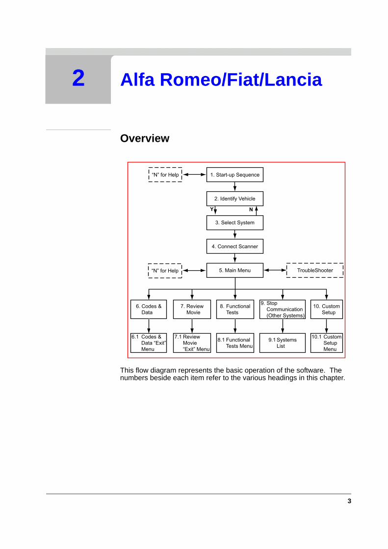
This flow diagram represents the basic operation of the software. The numbers beside each item refer to the various headings in this chapter.
1. Start-up Sequence“N” for Help
2. Identify Vehicle
3. Select System
4. Connect Scanner
5. Main Menu TroubleShooter
6. Codes &Data
7. ReviewMovie
8. FunctionalTests
9. StopCommunication(Other Systems)
10. CustomSetup
10.1 CustomSetupMenu
9.1 SystemsList
8.1 FunctionalTests Menu
7.1 ReviewMovie“Exit” Menu
6.1 Codes &Data “Exit”Menu
“N” for Help
Y N
4 Vehicle Communication Software 2009-02
C H A P T E R 2 ALFA ROMEO/FIAT/LANCIA
2.1 Start-up Sequence
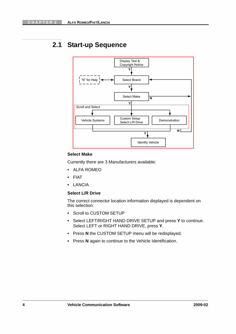
Select Make
Currently there are 3 Manufacturers available:
• ALFA ROMEO
• FIAT
• LANCIA
Select L/R Drive
The correct connector location information displayed is dependent on this selection:
• Scroll to CUSTOM SETUP
• Select LEFT/RIGHT HAND DRIVE SETUP and press Y to continue. Select LEFT or RIGHT HAND DRIVE, press Y.
• Press N the CUSTOM SETUP menu will be redisplayed.
• Press N again to continue to the Vehicle Identification.
Display Test &Copyright Notice
“N” for Help Select Brand
Select Make
Custom SetupSelect L/R DriveVehicle Systems Demonstration
Identify Vehicle
Scroll and Select
Y
N
Y
Y
Y
N
5
IDENTIFY VEHICLE
2.2 Identify Vehicle
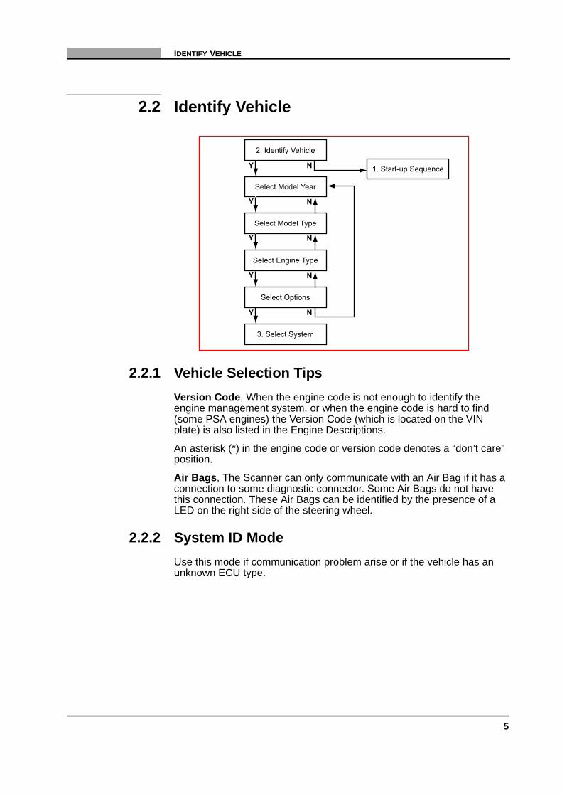
2.2.1 Vehicle Selection TipsVersion Code, When the engine code is not enough to identify the engine management system, or when the engine code is hard to find (some PSA engines) the Version Code (which is located on the VIN plate) is also listed in the Engine Descriptions.
An asterisk (*) in the engine code or version code denotes a “don’t care” position.
Air Bags, The Scanner can only communicate with an Air Bag if it has a connection to some diagnostic connector. Some Air Bags do not have this connection. These Air Bags can be identified by the presence of a LED on the right side of the steering wheel.
2.2.2 System ID ModeUse this mode if communication problem arise or if the vehicle has an unknown ECU type.
1. Start-up Sequence
2. Identify Vehicle
Select Model Year
Select Model Type
Select Engine Type
Select Options
3. Select System
Y N
Y
Y
Y N
Y N
N
N

6 Vehicle Communication Software 2009-02
C H A P T E R 2 ALFA ROMEO/FIAT/LANCIA
1. Select a system group from the list. Only fitted systems groups (engines, lights, seat, etc.) will be displayed.
2. After selecting the system group, select the system to be tested.
3. Connect the scanner and proceed testing.
2.3 Select System to be Tested
2.3.1 System ListThe system list will remain active until a new vehicle is selected. Scroll to the selected the system to be tested and press Y to confirm.
Note:i Refer to the Documentation CD for the complete list of Systems
available.
System List
Connect Scanner
Instruction Messages
System ID Mode
2. Identify Vehicle
5. Main Menu
Y N
Y
Y
System List
2. Identify Vehicle
5. Main Menu
4. Connect Scanner
3. Select System
Y N
Y
7
CONNECT SCANNER
2.3.2 Additional NotesNo Communication:
If there is NO COMMUNICATION to the selected System it is advisable to select the ECU type, if known, from the TEST entry to determine if the ECU is communicating or not.
This can be found in the Vehicle ID selection by choosing 1987 /TEST / the ECU name. All available ECU types are located here.
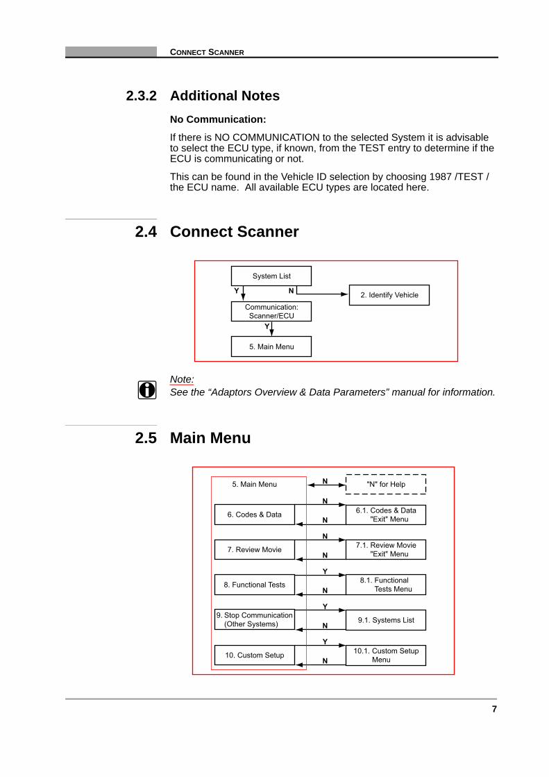
2.4 Connect Scanner
Note:i See the “Adaptors Overview & Data Parameters” manual for information.
2.5 Main Menu
System List
2. Identify Vehicle
5. Main Menu
Communication:Scanner/ECU
Y N
Y
6.1. Codes & Data"Exit" Menu6. Codes & Data
N
N
N
N
N
N
Y
N
Y
N
Y
7. Review Movie
8. Functional Tests
9. Stop Communication(Other Systems)
10. Custom Setup
"N" for Help5. Main Menu
7.1. Review Movie"Exit" Menu
8.1. FunctionalTests Menu
9.1. Systems List
10.1. Custom SetupMenu
8 Vehicle Communication Software 2009-02
C H A P T E R 2 ALFA ROMEO/FIAT/LANCIA
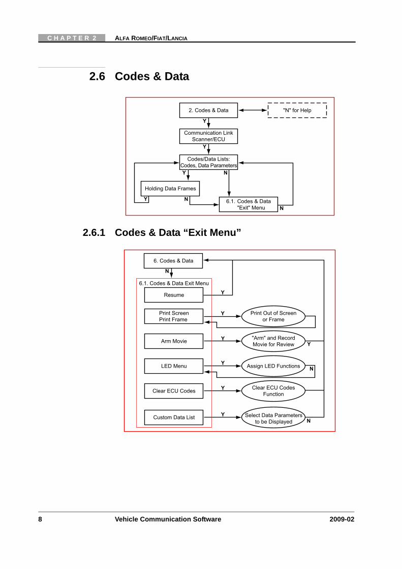
2.6 Codes & Data
2.6.1 Codes & Data “Exit Menu”
"N" for Help2. Codes & Data
Communication LinkScanner/ECU
Holding Data Frames
Y
Y
N
NY N
Codes/Data Lists:Codes, Data Parameters
6.1. Codes & Data"Exit" Menu
Y
Resume
N
Y
Y
N
Y
N
Y
Y
Print ScreenPrint Frame
Arm Movie
LED Menu
Clear ECU Codes
6.1. Codes & Data Exit Menu
6. Codes & Data
Custom Data List Select Data Parametersto be Displayed
Clear ECU CodesFunction
Assign LED Functions
"Arm" and RecordMovie for Review
Print Out of Screenor Frame
Y
Y
9
REVIEW MOVIE
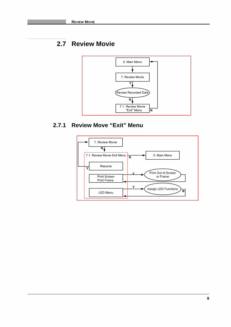
2.7 Review Movie
2.7.1 Review Move “Exit” Menu
7.1. Review Movie"Exit" Menu
5. Main Menu
7. Review Movie
Y
Review Recorded Data
N
N
Resume
N
Y
Y
N
N
Y
Print ScreenPrint Frame
LED Menu
7.1. Review Movie Exit Menu
7. Review Movie
Assign LED Functions
Print Out of Screenor Frame
5. Main Menu

10 Vehicle Communication Software 2009-02
C H A P T E R 2 ALFA ROMEO/FIAT/LANCIA
2.8 Functional Tests
Actuator Tests:
The number of actuators is dependent on the ECU and the vehicle:
• Injectors
• Idle Air Stepper Motor
• Air Conditioner Relay
• Purge Control Solenoid
• RPM Signal
• Fuel Consumption Signal
Special Functions, (Sub-menu), Example:
• Reset all Adaptations
• Reset Knock Sensor Adaptation
• Reset Idle Adaptation
• Reset O2 Adaptation
• Reset Throttle Adaptation
Y
N 8.1. Functional Tests Menu
5. Main Menu
"N" for Help8. Functional Tests
YReview ECU IDECU Information Y
YPrint ECU ID
Print Out ECUInformation
YFuel Adjust
Perform FuelAdjustments Y
YSpecial Functions
Special FunctionsMenu/Tests N
YIgnition Adjust
Perform IgnitionAdjustments Y
YActuator TestsPerform Actuator Tests Y

11
STOP COMMUNICATION, (OTHER SYSTEMS)
2.9 Stop Communication, (Other Systems)
Use STOP COMMUNICATION, (OTHER SYSTEMS) to select another system and to Stop Communication with the ECU.
2.10 Custom Setup
System ListSelect System
Connection Message
Select System"Main Menu"
2. Identify Vehicle
5. Main Menu
Y N
Y
9. Stop Communication(Other Systems)
"Data Loss"Warning Message
Y
N
"N" for Help
"N" for Help
Y
N 10.1. Custom Setup Menu
5. Main Menu
"N" for Help10. Custom Setup
YCommunication SetupSet Baud Rate Y
YImperial/MetricSet Display Units
YAbout
Display SoftwareVersion Information N
YContrast AdjustSet Backlight Automatic
Shut-off Times Y
YLED MenuAssign LED Functions N
12 Vehicle Communication Software 2009-02
C H A P T E R 2 ALFA ROMEO/FIAT/LANCIA
13
3 BMW
Overview
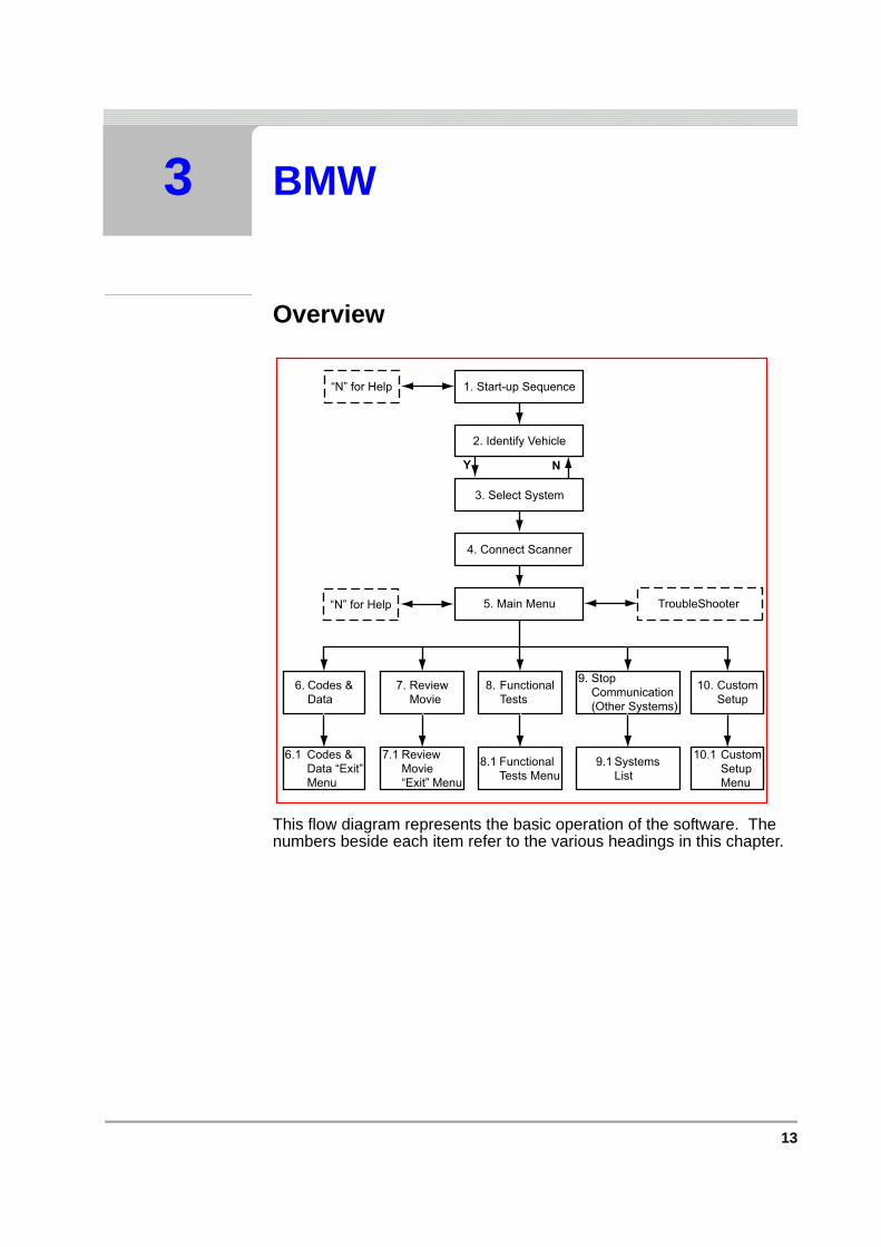
This flow diagram represents the basic operation of the software. The numbers beside each item refer to the various headings in this chapter.
1. Start-up Sequence“N” for Help
2. Identify Vehicle
3. Select System
4. Connect Scanner
5. Main Menu TroubleShooter
6. Codes &Data
7. ReviewMovie
8. FunctionalTests
9. StopCommunication(Other Systems)
10. CustomSetup
10.1 CustomSetupMenu
9.1 SystemsList
8.1 FunctionalTests Menu
7.1 ReviewMovie“Exit” Menu
6.1 Codes &Data “Exit”Menu
“N” for Help
Y N

14 Vehicle Communication Software 2009-02
C H A P T E R 3 BMW
3.1 Start-up Sequence
Select Make
Currently there is only one manufacturer available:
• BMW
Market Selection
The correct connector location information displayed is dependent on this selection:
• Select MARKET SELECTION
• Select EUROPEAN LHD, (Left Hand Drive) or EUROPEAN RHD, (Right Hand Drive) or USA LHD and press Y to continue.
• Select VEHICLE SYSTEMS and press Y to continue to the Vehicle Identification.
The European Left and Right Hand Drive selection differs in connector locations because the steering wheel is on different sides. The USA LHD selection differs because it uses another vehicle selection procedure. In the USA the Vehicle Identification Number (VIN) is used to make the vehicle selection.
Display Test &Copyright Notice
“N” for Help Select Brand
Select Make
VehicleSystems Demonstration
Identify Vehicle
Scroll and Select
Y
N
Y
Y
Y
N
CustomSetup
MarketSelection
SelectMarket
Y
15
IDENTIFY VEHICLE
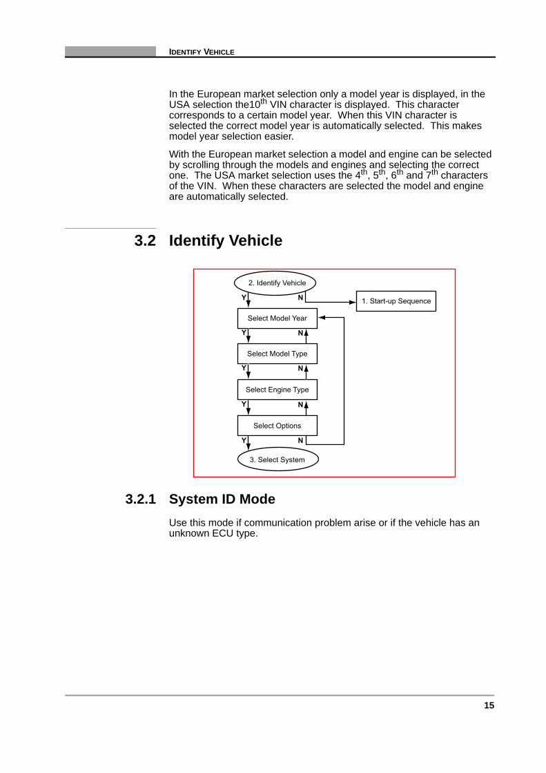
In the European market selection only a model year is displayed, in the USA selection the10th VIN character is displayed. This character corresponds to a certain model year. When this VIN character is selected the correct model year is automatically selected. This makes model year selection easier.
With the European market selection a model and engine can be selected by scrolling through the models and engines and selecting the correct one. The USA market selection uses the 4th, 5th, 6th and 7th characters of the VIN. When these characters are selected the model and engine are automatically selected.
3.2 Identify Vehicle
3.2.1 System ID ModeUse this mode if communication problem arise or if the vehicle has an unknown ECU type.
1. Start-up Sequence
2. Identify Vehicle
Select Model Year
Select Model Type
Select Engine Type
Select Options
3. Select System
Y N
Y
Y
Y N
Y N
N
N

16 Vehicle Communication Software 2009-02
C H A P T E R 3 BMW
1. Select a system group from the list. Only fitted systems groups (engines, lights, seat, etc.) will be displayed.
2. After selecting the system group, select the system to be tested.
3. Connect the scanner and proceed testing.
3.3 Select System to be Tested
3.3.1 System ListThe System List displayed is dependent on the selected vehicle.
Listed below are all of the possible systems that can be found in BMW vehicles:
• ENGINE
• ENGINE, (RIGHT
System List
Connect Scanner
Instruction Messages
System ID Mode
2. Identify Vehicle
5. Main Menu
Y N
Y
Y
System List
2. Identify Vehicle
5. Main Menu
4. Connect Scanner
3. Select System
Y N
Y
17
SELECT SYSTEM TO BE TESTED
• ENGINE, (LEFT)
• ENGINE, (MASTER)
• ENGINE, (SLAVE)
• EML/EMS
• VANOS
• AIRBAG
• ANTI-LOCK BRAKES
• TRANSMISSION
• AIRCO
The Engine (Right) and Engine (Left) selections are used on 12-cylinder engines that have two ECUs controlling the engine, one for each bank of cylinders.
The Engine (Master) and Engine (Slave) selections are used on 8-cylinder diesel engines that have two ECUs controlling the engine.
The EML/EMS selection is used on vehicles that have a drive-by-wire system, i.e. Electronic Throttle, etc.
The VANOS is a system that is used for controlling the position of the camshaft(s) on certain vehicles.
3.3.2 Additional Notes:No Communication:
If there is NO COMMUNICATION to the selected System it is advisable to select the ECU type, if known, from the TEST entry to determine if the ECU is communicating or not.
This can be found in the Vehicle ID selection by choosing 1987 /TEST (SYSTEM) / the type of ECU or system name. All available ECU types are divided into separate groups and are located here.
Communication Problems:
When the Scanner is unable to establish communication with the ECU in the vehicle under test, or when the communication is interrupted, a message will be displayed.
Wait to see whether the communication is established again or interrupted.
Press N to abort.
Switching off-and-on the ignition and a re-enter the ID may reset this.

18 Vehicle Communication Software 2009-02
C H A P T E R 3 BMW
Note:i When testing a BMW with certain Motronics, (M1.1, M1.2, M1.3)
communication problems may occur when the engine revs are above 2000 rpm. In this case communication cannot be built up. Once communication has been established, the engine may be revved above 2000 rpm.
Note:i When testing EML or Automatic Gearbox systems the engine MUST be
off and the gearbox must be in Park or Neutral in order to establish communications. Once communication is built up, the engine may be started and the gearbox can be set into Drive.
3.4 Connect Scanner
Note:i Refer to the “Adaptors Overview & Data Parameters” manual for
connection information.
System List
2. Identify Vehicle
5. Main Menu
Communication:Scanner/ECU
Y N
Connector Location
Connection Messages
Y
Y
19
MAIN MENU
3.5 Main Menu
3.6 Codes & Data
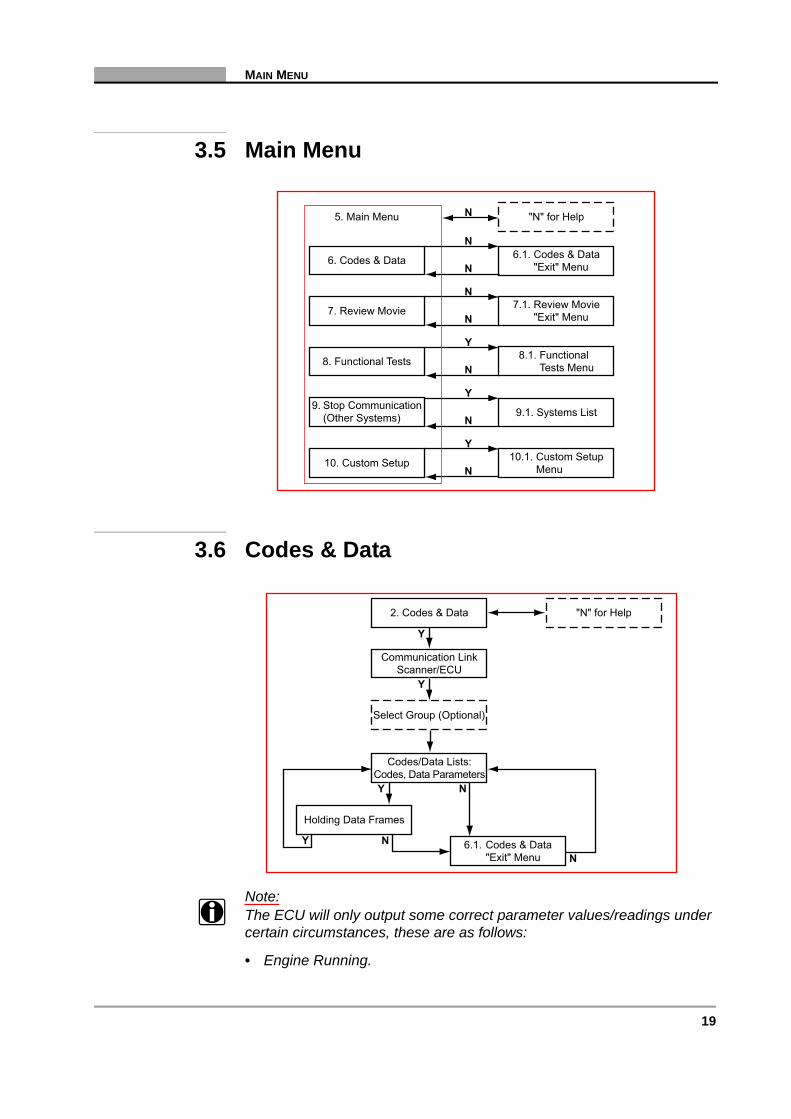
Note:i The ECU will only output some correct parameter values/readings under
certain circumstances, these are as follows:
• Engine Running.
6.1. Codes & Data"Exit" Menu6. Codes & Data
N
N
N
N
N
N
Y
N
Y
N
Y
7. Review Movie
8. Functional Tests
9. Stop Communication(Other Systems)
10. Custom Setup
"N" for Help5. Main Menu
7.1. Review Movie"Exit" Menu
8.1. FunctionalTests Menu
9.1. Systems List
10.1. Custom SetupMenu
"N" for Help2. Codes & Data
Communication LinkScanner/ECU
Holding Data Frames
Y
Y
N
NY N
Codes/Data Lists:Codes, Data Parameters
6.1. Codes & Data"Exit" Menu
Y
Select Group (Optional)

20 Vehicle Communication Software 2009-02
C H A P T E R 3 BMW
• Engine Temperature has reached working temperature.
• All electrical consumers including air-conditioning are switched off
Check these circumstances if the displayed parameters seem incorrect.
Note:i When checking some BMW-Motronic’s e.g. DDE1, DDE2 and Motronic
M1.1 and M1.3 my. 87/88 a maximum of 5 Fault codes can be displayed.
Note:i To be able to display the remaining Fault Codes (if any), the first Fault
Codes must be repaired first.
3.6.1 Codes & Data “Exit” Menu
3.6.1.1 Notes to Clear Codes
Note:i Sometimes a fault code is displayed of a component which is not
installed in the vehicle under test, e.g. a cruise control for BMW. This code can’t be cleared. Always make sure the component, the code refers to, is present, when a code can’t be cleared.
Note:i Be aware, some codes only set again under certain circumstances.
Note or print the codes before repair and before clearing codes.
Resume
N
Y
Y
N
Y
N
Y
Y
Print ScreenPrint Frame
Arm Movie
LED Menu
Clear ECU Codes
6.1. Codes & Data Exit Menu
6. Codes & Data
Custom Data List Select Data Parametersto be Displayed
Clear ECU CodesFunction
Assign LED Functions
"Arm" and RecordMovie for Review
Print Out of Screenor Frame
Y
Y

21
REVIEW MOVIE
Note:i When the error condition still exists, the ECU can set the code again.
3.7 Review Movie
3.7.1 Review Movie “Exit” Menu
7.1. Review Movie"Exit" Menu
5. Main Menu
7. Review Movie
Y
Review Recorded Data
N
N
Resume
N
Y
Y
N
N
Y
Print ScreenPrint Frame
LED Menu
7.1. Review Movie Exit Menu
7. Review Movie
Assign LED Functions
Print Out of Screenor Frame
5. Main Menu
22 Vehicle Communication Software 2009-02
C H A P T E R 3 BMW
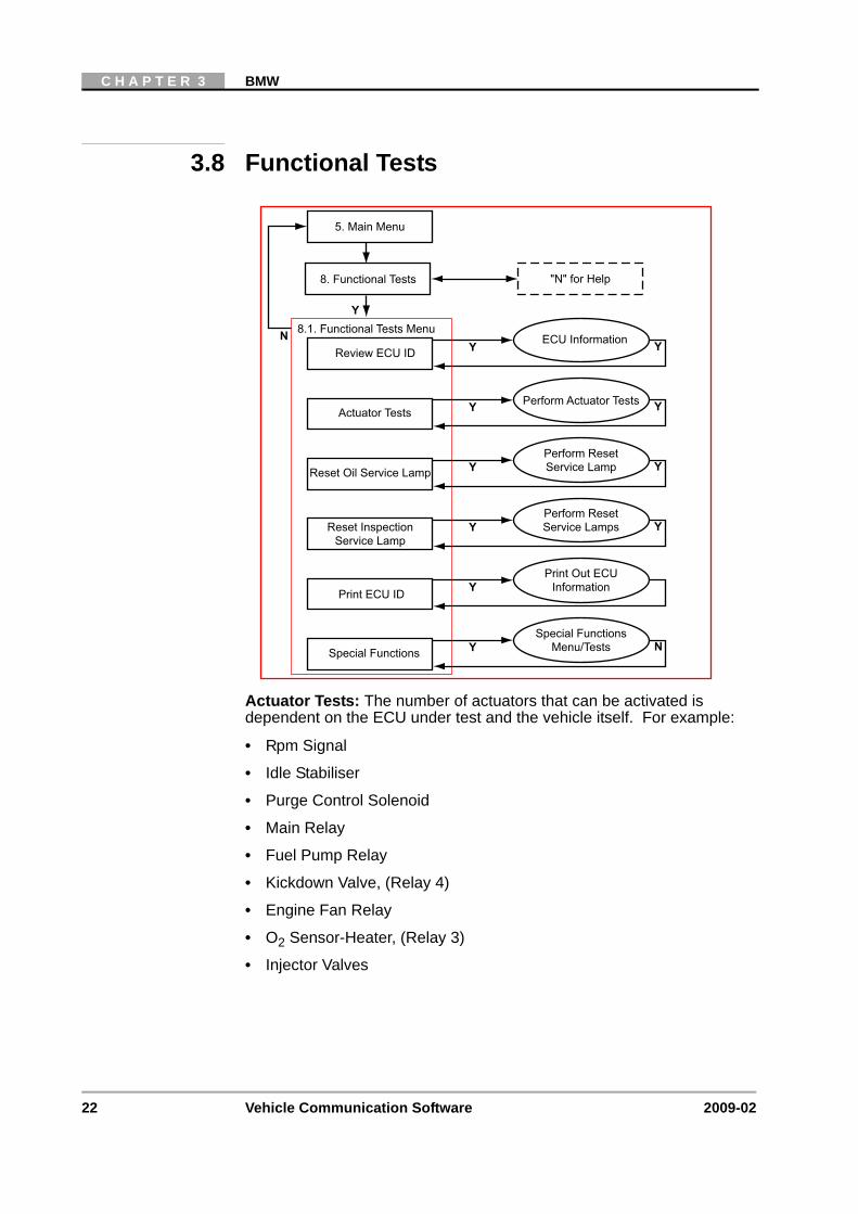
3.8 Functional Tests
Actuator Tests: The number of actuators that can be activated is dependent on the ECU under test and the vehicle itself. For example:
• Rpm Signal
• Idle Stabiliser
• Purge Control Solenoid
• Main Relay
• Fuel Pump Relay
• Kickdown Valve, (Relay 4)
• Engine Fan Relay
• O2 Sensor-Heater, (Relay 3)
• Injector Valves
Y
N 8.1. Functional Tests Menu
5. Main Menu
"N" for Help8. Functional Tests
YReview ECU IDECU Information Y
YPrint ECU ID
Print Out ECUInformation
YReset InspectionService Lamp
Perform ResetService Lamps Y
YSpecial Functions
Special FunctionsMenu/Tests N
YReset Oil Service Lamp
Perform ResetService Lamp Y
YActuator TestsPerform Actuator Tests Y
23
FUNCTIONAL TESTS
3.8.1 BMW Engines, Actuator Tests Notes:
Note:i Often a certain actuator may not be present on a vehicle, although
according to the manuals it should be. Therefore, please check this first after failing to hear a reaction from the actuator under test.
Note:i Have the engine running only when instructed to do so by the Scanner
and always follow the instructions displayed on the Scanner.
Note:i Some actuators can not be stopped during the 30 seconds period by
pressing N, (e.g. Diesel with a DDE2.1 ECU). It is recommended to wait for the 30 seconds to end.
Note:i With some engines, (e.g. Motronic 1.7 and 1.7.2) it is very difficult to
hear the injectors click. Use a multi meter or scope to make sure the injectors are activated properly.
Note:i Some actuators will be activated for a short time. For example, the
injectors will be activated for only five seconds, this is for safety reasons.
3.8.2 Reset Service Lamps, Notes:
Note:i The Reset Service Lamps functions are only possible when using the
BM-1B Adaptor.
Note:i The Scanner will extinguish the OIL SERVICE or INSPECTION
SERVICE LAMPS and light all the green service indicator bar LEDs. Once the Scanner has reset these lamps they can not be returned to their previous states. Make sure that these lamps need to be reset before performing this function.
Note:i The resetting process can take up to 30 seconds to be performed.
3.8.3 Special Functions, (Sub-menu), Example• Reset All Adaptations
• Reset Knock Adaptations
• Reset Idle Adaptations
24 Vehicle Communication Software 2009-02
C H A P T E R 3 BMW
• Reset O2 Adaptations
• Reset Throttle Adaptations
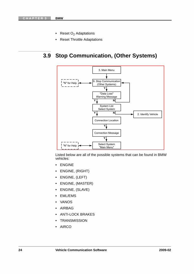
3.9 Stop Communication, (Other Systems)
Listed below are all of the possible systems that can be found in BMW vehicles:
• ENGINE
• ENGINE, (RIGHT)
• ENGINE, (LEFT)
• ENGINE, (MASTER)
• ENGINE, (SLAVE)
• EML/EMS
• VANOS
• AIRBAG
• ANTI-LOCK BRAKES
• TRANSMISSION
• AIRCO
System ListSelect System
Connection Message
Select System"Main Menu"
2. Identify Vehicle
5. Main Menu
Y N
Y
9. Stop Communication(Other Systems)
"Data Loss"Warning Message
Y N
"N" for Help
"N" for Help
Connection Location
Y
Y

25
CUSTOM SETUP
Caution:ä The ABS System or the ECU can be damaged or disabled if the
Scanner is disconnected before communication has properly stopped. Always return to the Main Menu and select “Stop Communication, (Other Systems)” before disconnecting the Scanner.
3.10 Custom Setup
Y
N 10.1. Custom Setup Menu
5. Main Menu
"N" for Help10. Custom Setup
YCommunication SetupSet Baud Rate Y
YImperial/MetricSet Display Units
YAbout
Display SoftwareVersion Information N
YContrast AdjustSet Backlight Automatic
Shut-off Times Y
YLED MenuAssign LED Functions N

26 Vehicle Communication Software 2009-02
C H A P T E R 3 BMW
27
4 Citroën
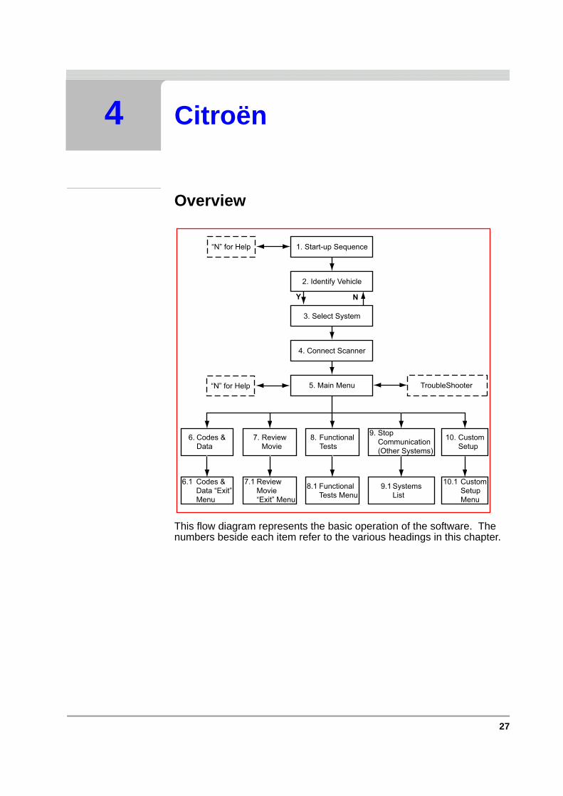
Overview
This flow diagram represents the basic operation of the software. The numbers beside each item refer to the various headings in this chapter.
1. Start-up Sequence“N” for Help
2. Identify Vehicle
3. Select System
4. Connect Scanner
5. Main Menu TroubleShooter
6. Codes &Data
7. ReviewMovie
8. FunctionalTests
9. StopCommunication(Other Systems)
10. CustomSetup
10.1 CustomSetupMenu
9.1 SystemsList
8.1 FunctionalTests Menu
7.1 ReviewMovie“Exit” Menu
6.1 Codes &Data “Exit”Menu
“N” for Help
Y N
28 Vehicle Communication Software 2009-02
C H A P T E R 4 CITROËN
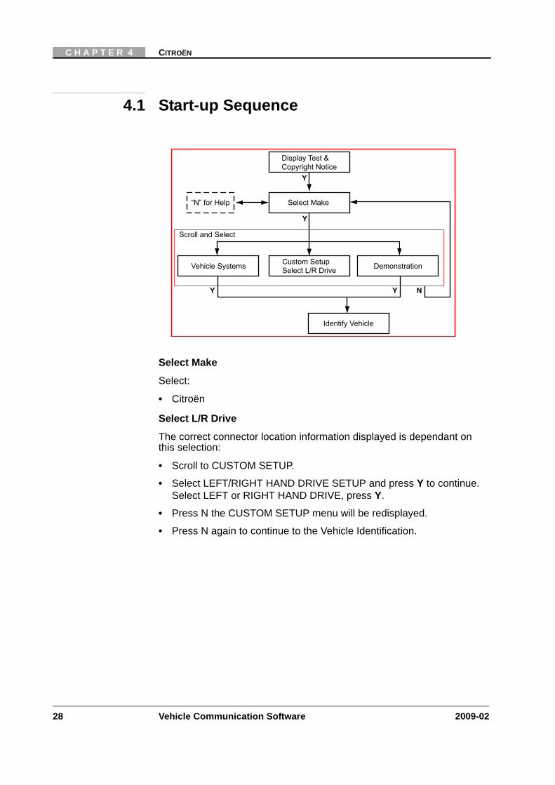
4.1 Start-up Sequence
Select Make
Select:
• Citroën
Select L/R Drive
The correct connector location information displayed is dependant on this selection:
• Scroll to CUSTOM SETUP.
• Select LEFT/RIGHT HAND DRIVE SETUP and press Y to continue. Select LEFT or RIGHT HAND DRIVE, press Y.
• Press N the CUSTOM SETUP menu will be redisplayed.
• Press N again to continue to the Vehicle Identification.
Display Test &Copyright Notice
“N” for Help Select Make
Custom SetupSelect L/R DriveVehicle Systems Demonstration
Identify Vehicle
Scroll and Select
Y Y
Y
Y
N
29
IDENTIFY VEHICLE
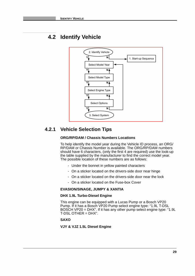
4.2 Identify Vehicle
4.2.1 Vehicle Selection TipsORG/RP/DAM / Chassis Numbers Locations
To help identify the model year during the Vehicle ID process, an ORG/RP/DAM or Chassis Number is available. The ORG/RP/DAM numbers should have 6 characters, (only the first 4 are required) use the look-up the table supplied by the manufacturer to find the correct model year. The possible location of these numbers are as follows:
- Under the bonnet in yellow painted characters- On a sticker located on the drivers-side door near hinge- On a sticker located on the drivers-side door near the lock- On a sticker located on the Fuse-box Cover
EVASION/SINAGE, JUMPY & XANTIA
DHX 1.9L Turbo-Diesel Engine
This engine can be equipped with a Lucas Pump or a Bosch VP20 Pump. If it has a Bosch VP20 Pump select engine type: “1.9L T-DSL BOSCH VP20 = DHX”. If it has any other pump select engine type: “1.9L T-DSL OTHER = DHX”.
SAXO
VJY & VJZ 1.5L Diesel Engine
1. Start-up Sequence
2. Identify Vehicle
Select Model Year
Select Model Type
Select Engine Type
Select Options
3. Select System
Y N
Y
Y
Y N
Y N
N
N
30 Vehicle Communication Software 2009-02
C H A P T E R 4 CITROËN
This engine can be equipped with a Lucas Pump or a Bosch VP20 Pump. If it has a Bosch VP20 Pump select engine type: “1.5L DIESEL BOSCH VP20 = VJY”. If it has any other pump select engine type: “1.5L DIESEL OTHER = VJY”. When it is a VJZ type engine use the same entries for the VJZ engine.
XM
The XM up to model year 1994 has a 2-pin connector located on the front of the ECU in the engine compartment. XMs from model year 1995 and later have a 30-pin connector located behind a panel on the lower dashboard. So, when a vehicle has a 2-pin connector it is a 1994 or older and if it has a 30-pin connector it is a 1995 or later.
Air Bags
The Scanner can only communicate with an Air Bag if it has a connection to the diagnostic connector. Some Air Bags do not have this connection. These Air Bags can be identified by the presence of a LED on the right side of the steering wheel.
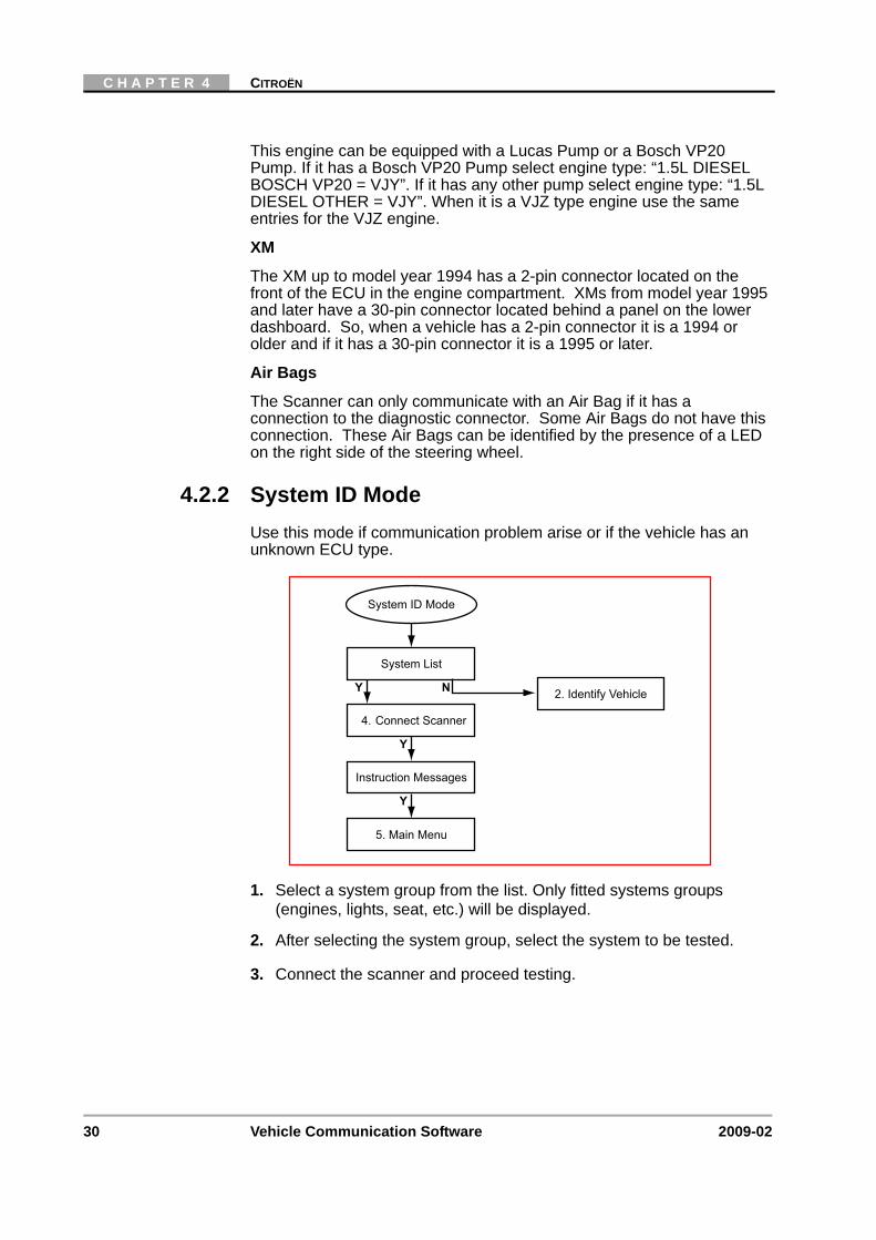
4.2.2 System ID ModeUse this mode if communication problem arise or if the vehicle has an unknown ECU type.
1. Select a system group from the list. Only fitted systems groups (engines, lights, seat, etc.) will be displayed.
2. After selecting the system group, select the system to be tested.
3. Connect the scanner and proceed testing.
System List
4. Connect Scanner
Instruction Messages
System ID Mode
2. Identify Vehicle
5. Main Menu
Y N
Y
Y
31
SELECT SYSTEM TO BE TESTED
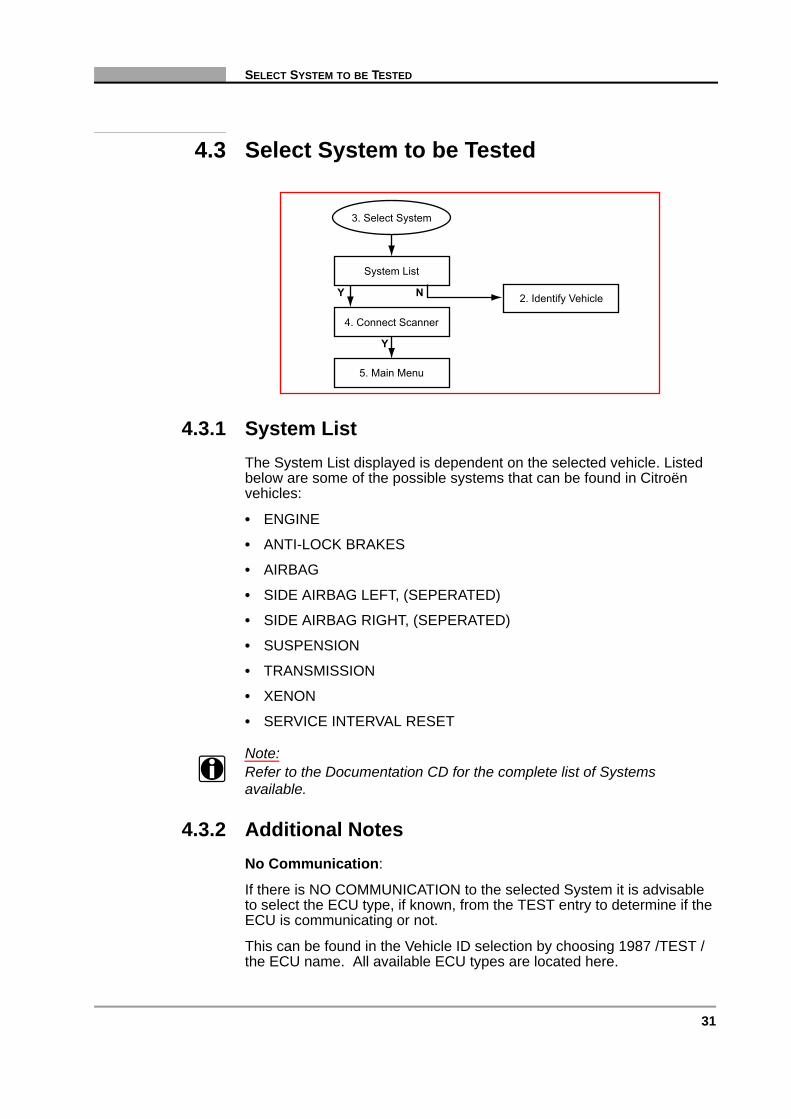
4.3 Select System to be Tested
4.3.1 System ListThe System List displayed is dependent on the selected vehicle. Listed below are some of the possible systems that can be found in Citroën vehicles:
• ENGINE
• ANTI-LOCK BRAKES
• AIRBAG
• SIDE AIRBAG LEFT, (SEPERATED)
• SIDE AIRBAG RIGHT, (SEPERATED)
• SUSPENSION
• TRANSMISSION
• XENON
• SERVICE INTERVAL RESET
Note:i Refer to the Documentation CD for the complete list of Systems
available.
4.3.2 Additional NotesNo Communication:
If there is NO COMMUNICATION to the selected System it is advisable to select the ECU type, if known, from the TEST entry to determine if the ECU is communicating or not.
This can be found in the Vehicle ID selection by choosing 1987 /TEST / the ECU name. All available ECU types are located here.
System List
2. Identify Vehicle
5. Main Menu
4. Connect Scanner
3. Select System
Y N
Y

32 Vehicle Communication Software 2009-02
C H A P T E R 4 CITROËN
Unavailable Data Parameters:
If there is a Data Parameter in the Screen Data List that is not mounted on the engine, then ignore it. For example the EDC15 System, this is the HDI (High Diesel Injection) Turbo Diesel system mounted on the RHS, RHV, RHX, RHY and RHZ engines. The Screen Data List consists of Data Parameters including MAP sensor and Airflow sensor. Most if not all of these engines are fitted with both sensors. But if there is an engine that is not fitted with one of these sensors disregard the Data Parameter in question.
Note:i When testing certain vehicles, communication problems may occur when
the engine revs are above 2000 rpm. In this case communication cannot be built up. Once communication has been re-established, the engine may be revved above 2000 rpm.
4.4 Connect Scanner
Note:i Refer to the “Adaptors Overview & Data Parameters” manual for
connection information.
System List
2. Identify Vehicle
5. Main Menu
Communication:Scanner/ECU
Y N
Connection Messages
Y

33
MAIN MENU
4.5 Main Menu
4.6 Codes & Data
6.1. Codes & Data"Exit" Menu6. Codes & Data
N
N
N
N
N
N
Y
N
Y
N
Y
7. Review Movie
8. Functional Tests
9. Stop Communication(Other Systems)
10. Custom Setup
"N" for Help5. Main Menu
7.1. Review Movie"Exit" Menu
8.1. FunctionalTests Menu
9.1. Systems List
10.1. Custom SetupMenu
"N" for Help2. Codes & Data
Communication LinkScanner/ECU
Holding Data Frames
Y
Y
N
NY N
Codes/Data Lists:Codes, Data Parameters
6.1. Codes & Data"Exit" Menu
Y

34 Vehicle Communication Software 2009-02
C H A P T E R 4 CITROËN
4.6.1 Codes & Data “Exit” menu
4.6.1.1 Notes to Clear ECU Codes
Note:i Be aware, some codes can only be set again under certain
circumstances. Note or print the codes before repair and before clearing codes.
Note:i When the error condition still exists, the code can be set again by the
ECU.
Note:i When codes are cleared, the Fuel Pump Relay can be activated for
some time and the “No Communication” message is displayed for a while.
Note:i Some Trouble Codes may be sent several times per Data Frame. These
Codes will be displayed a number of times in the Code List.
Resume
N
Y
Y
N
Y
N
Y
Y
Print ScreenPrint Frame
Arm Movie
LED Menu
Clear ECU Codes
6.1. Codes & Data Exit Menu
6. Codes & Data
Custom Data List Select Data Parametersto be Displayed
Clear ECU CodesFunction
Assign LED Functions
"Arm" and RecordMovie for Review
Print Out of Screenor Frame
Y
Y

35
REVIEW MOVIE
4.7 Review Movie
4.7.1 Review Movie “Exit” Menu
7.1. Review Movie"Exit" Menu
5. Main Menu
7. Review Movie
Y
Review Recorded Data
N
N
Resume
N
Y
Y
N
N
Y
Print ScreenPrint Frame
LED Menu
7.1. Review Movie Exit Menu
7. Review Movie
Assign LED Functions
Print Out of Screenor Frame
5. Main Menu
36 Vehicle Communication Software 2009-02
C H A P T E R 4 CITROËN
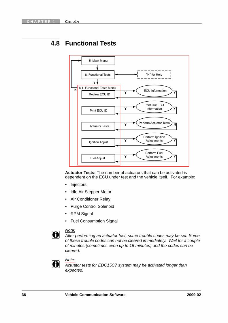
4.8 Functional Tests
Actuator Tests: The number of actuators that can be activated is dependent on the ECU under test and the vehicle itself. For example:
• Injectors
• Idle Air Stepper Motor
• Air Conditioner Relay
• Purge Control Solenoid
• RPM Signal
• Fuel Consumption Signal
Note:i After performing an actuator test, some trouble codes may be set. Some
of these trouble codes can not be cleared immediately. Wait for a couple of minutes (sometimes even up to 15 minutes) and the codes can be cleared.
Note:i Actuator tests for EDC15C7 system may be activated longer than
expected.
Y
N 8.1. Functional Tests Menu
5. Main Menu
"N" for Help8. Functional Tests
YReview ECU IDECU Information Y
YPrint ECU ID
Print Out ECUInformation
YFuel Adjust
Perform FuelAdjustments Y
YIgnition Adjust
Perform IgnitionAdjustments Y
YActuator TestsPerform Actuator Tests N
Y

37
FUNCTIONAL TESTS
Note:i Often a certain actuator may not be present on a vehicle, although
according to the manuals it should be. Therefore, please check this first after failing to hear a reaction from the actuator under test. Have the engine running only when instructed to do so by the Scanner.
Ignition Adjust
Use this test to increase or decrease the ignition correction. The ignition can be increased from -8 to 0° and can be decreased from 0 to -8°. Select END and press Y to exit this test.
Fuel Adjust
Use this test to increase or decrease the CO correction. The engine must be running to perform this test. The CO correction can be increased from -24 to 54 and can be decreased from 54 to -24, (the values displayed are dependant on the MAP sensor and the ECU). Select END and press Y to exit this test.
Note:i For both the Ignition and the Fuel Adjustments, the maximum and
minimum adjustment values are dependant on the ECU type.
Pedal Calibration Test
For Citroën SAXO there is a Calibration Pedal Test to be performed after the Clearing Codes has been completed.
The Calibration Test is also available in the FUNCTIONAL TESTS MENU. So for the Citroën Xantia and Xsara the test is carried out here.
Calibration Pedal Note
Use this test to calibrate the throttle pedal for the automatic transmission system. The gear lever must be in the PARK position during this test. The maximum and minimum pedal position need to be determined in this test, by pressing and releasing the pedal fully. When the test is complete it exits to the FUNCTIONAL TESTS Menu.
38 Vehicle Communication Software 2009-02
C H A P T E R 4 CITROËN
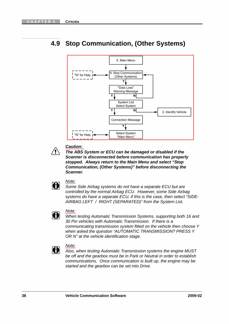
4.9 Stop Communication, (Other Systems)
Caution:ä The ABS System or ECU can be damaged or disabled if the
Scanner is disconnected before communication has properly stopped. Always return to the Main Menu and select “Stop Communication, (Other Systems)” before disconnecting the Scanner.
Note:i Some Side Airbag systems do not have a separate ECU but are
controlled by the normal Airbag ECU. However, some Side Airbag systems do have a separate ECU, if this is the case, then select “SIDE-AIRBAG LEFT / RIGHT (SEPARATED)” from the System List.
Note:i When testing Automatic Transmission Systems, supporting both 16 and
30 Pin vehicles with Automatic Transmission. If there is a communicating transmission system fitted on the vehicle then choose Y when asked the question “AUTOMATIC TRANSMISSION? PRESS Y OR N” at the vehicle identification stage.
Note:i Also, when testing Automatic Transmission systems the engine MUST
be off and the gearbox must be in Park or Neutral in order to establish communications. Once communication is built up, the engine may be started and the gearbox can be set into Drive.
System ListSelect System
Connection Message
Select System"Main Menu"
2. Identify Vehicle
5. Main Menu
Y N
Y
9. Stop Communication(Other Systems)
"Data Loss"Warning Message
Y N
"N" for Help
"N" for Help
Y

39
CUSTOM SETUP
Note:i When testing the following systems, the Trouble Code list may be
incomplete:
• Bosch ABS 5.3 ESP
• Bosh ABS 8
• Siemens Airbag Through Central
• Temic MK70
Undocumented Code: (especially for 2000+ models).
If undocumented Codes are received it is advisable to check the manuals for the relevant Trouble Code numbers, especially if they are OBD codes on the newer ECUs.
Transmission Systems Note
For Citroën SAXO there is a Calibration Pedal Test to be performed after the Clearing Codes is completed. Use the Functional Tests menu to perform the Calibration Pedal Test.
4.10 Custom Setup
Y
N 10.1. Custom Setup Menu
5. Main Menu
"N" for Help10. Custom Setup
YCommunication SetupSet Baud Rate Y
YImperial/MetricSet Display Units
YAbout
Display SoftwareVersion Information N
YContrast AdjustSet Backlight Automatic
Shut-off Times Y
YLED MenuAssign LED Functions N

40 Vehicle Communication Software 2009-02
C H A P T E R 4 CITROËN
41
5 Ford
Overview
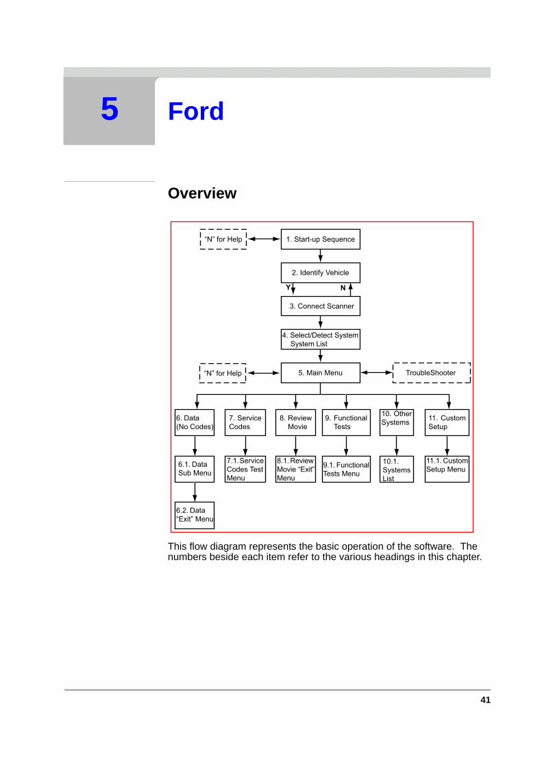
This flow diagram represents the basic operation of the software. The numbers beside each item refer to the various headings in this chapter.
1. Start-up Sequence“N” for Help
2. Identify Vehicle
3. Connect Scanner
5. Main Menu TroubleShooter
11. CustomSetup
11.1. CustomSetup Menu
10. OtherSystems
10.1.SystemsList
8. ReviewMovie
8.1. ReviewMovie “Exit”Menu
“N” for Help
Y N
4. Select/Detect SystemSystem List
6. Data(No Codes)
6.1. DataSub Menu
6.2. Data“Exit” Menu
7. ServiceCodes
7.1.ServiceCodes TestMenu
9. FunctionalTests
9.1. FunctionalTests Menu
42 Vehicle Communication Software 2009-02
C H A P T E R 5 FORD
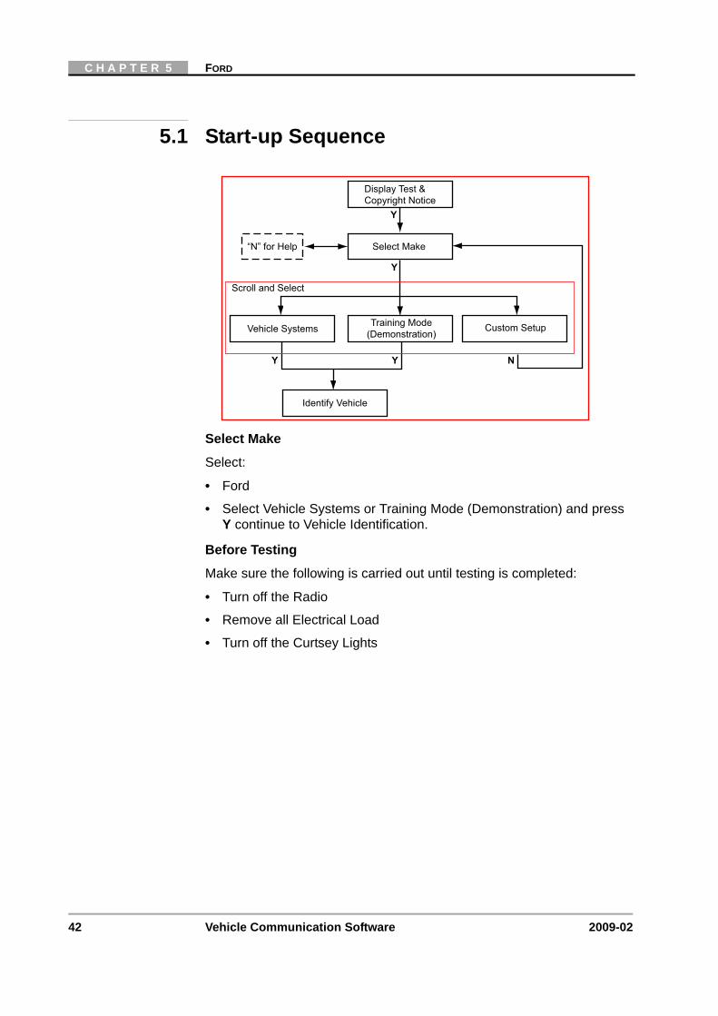
5.1 Start-up Sequence
Select Make
Select:
• Ford
• Select Vehicle Systems or Training Mode (Demonstration) and press Y continue to Vehicle Identification.
Before Testing
Make sure the following is carried out until testing is completed:
• Turn off the Radio
• Remove all Electrical Load
• Turn off the Curtsey Lights
Display Test &Copyright Notice
“N” for Help Select Make
Vehicle Systems Training Mode(Demonstration)
Identify Vehicle
Scroll and Select
Y Y
Y
Y
N
Custom Setup

43
IDENTIFY VEHICLE
5.2 Identify Vehicle
In order to help with the Vehicle ID process, in some cases the engine letter code can be found on the VIN plate. See example below:
Figure 5-1 2003, Ford Focus, 1.8L DURATORQ TDCI=L
Note:i Be aware that this is not true for all vehicles, such as older models.
1. Start-up Sequence
2. Identify Vehicle
Select Model Year
Select Model Type
Select Engine Type
Select Options
3. Connect Scanner
Y N
Y
Y
Y N
Y N
N
N

44 Vehicle Communication Software 2009-02
C H A P T E R 5 FORD
5.3 Connect Scanner
Note:i Refer to the “Adaptors Overview & Data Parameters” manual for details.
Additional Information, Mazda Electronic Control Systems (MECS)
The MULTI-1 Adaptor (MT2500-90), (Optional) or the GA-1 Adaptor (recommended) is used on Mazda Electronic Control Systems (MECS) self-test connectors.
Figure 5-2 Ford connections that need the MULTI-1 Test Adaptor. Colour coding refers to the colours of the leads of the MULTI-1 adaptor, MT2500-90.
Caution:ä Do not connect the Scanner to the MECS TACH connector. Doing
so can severely damage the Scanner.
Caution:ä Connecting to the wrong Data Link Communication (DLC) pins can
cause a possible malfunction. Carefully connect to the specified pins only.
Select/Detect SystemsSystem List
2. Identify Vehicle
5. Main Menu
Communication:Scanner/ECU
Y N
Connection MessagesConnect Scanner
Y
Battery +
Not Used
Black(Ground)
Blue
Brown
Red(Engine STI)
Mazda Electronic Control System (MECS) 17-Pin Connector

45
SELECT/DETECT SYSTEM TO BE TESTED
5.4 Select/Detect System to be Tested
Note:i Turn the Ignition Key ON and wait at least 30 seconds before using the
Auto-detect Functions.
Depending on the vehicle selected, the System Select/Detect menu will be displayed.
Scroll and press Y to detect/select the system for testing.
Use the detect systems to list all of the systems available on the vehicle As each system is detected, it will be added to the system list.
To automatically detect each system installed, select the detect option and press Y to confirm. Follow all instructions displayed and allow some time for the automatic detection and communication with the systems.
To automatically detect all the Sub-Systems, select HELP, scroll down to the end of the help text and press Y to “Enable All Systems”. A further Message will be displayed, press Y to return or N to “Enable All Systems”. If N is pressed the Scanner will enable all of the systems and sub-systems available on the selected vehicle.
It is also possible to enable a system or a sub-system that is not found with the auto-detect. For example, if the vehicle has a faulty or non-communicating accessory system installed, then manually select accessory systems.
5.4.1 System ListThe systems list will remain active until a new vehicle is selected. Scroll to the selected the system to be tested and press Y to confirm.
Note:i Refer to the Documentation CD for a complete list of available systems.
Note:i Refer to Section 5.12: ‘Special Ford Galaxy Systems’ on page 58 of this
Chapter for information concerning the “Special Ford Galaxy Systems”.
System List
2. Identify Vehicle
5. Main Menu
3. Select/DeselectSystem
Y N
46 Vehicle Communication Software 2009-02
C H A P T E R 5 FORD
5.4.2 CAN Systems Notes
Note:i The CAN adaptor needs to be updated for testing CAN systems.
Detection of the 1st CAN system may take longer, up to 1 minute.
Note:i The ECU may time out if the ignition is switched ON for too long. It is
important to Cycle the ignition to OFF for 15 seconds, then ON for 15 seconds periodically. If however a “No Communication” occurs CYCLE THE IGNITION as stated above before retrying test.
Note:i When the user is asked to change to the S-43 Key, the ignition must be
switched OFF and ON again after 15 seconds. Then select the required system using the Auto-detect function.
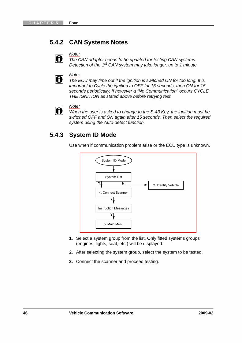
5.4.3 System ID ModeUse when if communication problem arise or the ECU type is unknown.
1. Select a system group from the list. Only fitted systems groups (engines, lights, seat, etc.) will be displayed.
2. After selecting the system group, select the system to be tested.
3. Connect the scanner and proceed testing.
System List
4. Connect Scanner
Instruction Messages
System ID Mode
2. Identify Vehicle
5. Main Menu
Y N
Y
Y

47
MAIN MENU
5.5 Main Menu
5.5.1 Main Menu SelectionsData (No Codes) — allows the monitoring of various sensors, switches and actuator inputs/outputs on vehicles with Data Communication Link (DCL) EEC-IV and EEC-V controllers.
Service Codes — allows the operator to perform Key-On, Engine-Off (KOEO) and Key-On, Engine-Running (KOER) self-tests and review codes after performing these self-tests.
7.1. Service CodesMenu
7. Service CodesN
Y
N
N
N
Y
N
Y
N
Y
8. Review Movie
9. Functional Tests
10. Stop Communication(Other Systems)
11. Custom Setup
8.1. Review Movie"Exit" Menu
9.1. FunctionalTests Menu
10.1. Systems List
11.1. Custom SetupMenu
N "N" for Help5. Main Menu
6.1. Data Sub Menu6. Data (No Codes) N
N
N
Y
N
Y
Select Data Parametersto be Displayed
Data ParametersDisplay
6.2. Data "Exit" Menu
48 Vehicle Communication Software 2009-02
C H A P T E R 5 FORD
5.6 Data (No Codes)
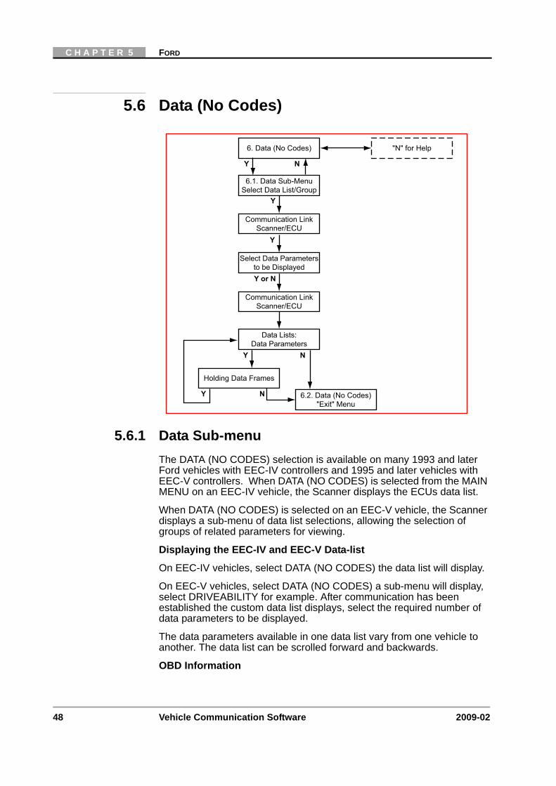
5.6.1 Data Sub-menuThe DATA (NO CODES) selection is available on many 1993 and later Ford vehicles with EEC-IV controllers and 1995 and later vehicles with EEC-V controllers. When DATA (NO CODES) is selected from the MAIN MENU on an EEC-IV vehicle, the Scanner displays the ECUs data list.
When DATA (NO CODES) is selected on an EEC-V vehicle, the Scanner displays a sub-menu of data list selections, allowing the selection of groups of related parameters for viewing.
Displaying the EEC-IV and EEC-V Data-list
On EEC-IV vehicles, select DATA (NO CODES) the data list will display.
On EEC-V vehicles, select DATA (NO CODES) a sub-menu will display, select DRIVEABILITY for example. After communication has been established the custom data list displays, select the required number of data parameters to be displayed.
The data parameters available in one data list vary from one vehicle to another. The data list can be scrolled forward and backwards.
OBD Information
Communication LinkScanner/ECU
"N" for Help
6.1. Data Sub-MenuSelect Data List/Group
6. Data (No Codes)
Select Data Parametersto be Displayed
Data Lists:Data Parameters
6.2. Data (No Codes)"Exit" Menu
Communication LinkScanner/ECU
Holding Data Frames
Y N
Y
Y
Y or N
Y N
NY

49
FORD SERVICE CODES
These selections display information concerning the OBD (On-Board Diagnostics) related data and fault codes:
• READINESS MONITORS
• OBD DATA
• OBD FREEZE FRAME
Select READINESS MONITORS and press Y to confirm.
Scroll to display the data, when complete press N twice to return.
Select OBD FREEZE FRAME and press Y to confirm. If the vehicle does not support OBD Freeze Frame or if there is no Freeze Frame stored a “no information available” message is displayed.
If the vehicle supports OBD Freeze Frame, the data will be displayed.
Scroll to display the data, when complete press N twice to return.
5.6.2 Data (No Codes) “Exit” Menu
5.7 Ford Service CodesFord refers to service codes as on-demand codes and KAM codes. On-demand codes are “hard” codes that occur during a Key-On, Engine-Off (KOEO) self-test, or a Key-On, Engine-Running (KOER) self-test. KAM codes are “soft” memory codes from the power-train control module (PCM). These indicate intermittent problems that have occurred in the past, during normal vehicle operation. Memory codes cannot be set while running a self-test. Some codes can only set as KAM (Keep Alive Memory) codes.
Resume
N
Y
Y
N
Y
Y
Print ScreenPrint Frame
Arm Movie
LED Menu
6.1. Data (No Codes) Exit Menu
6. Data (No Codes)
Assign LED Functions
"Arm" and RecordMovie for Review
Print Out of Screenor Frame
Y

50 Vehicle Communication Software 2009-02
C H A P T E R 5 FORD
During the KOEO self-test:
• EEC-IV systems transmit hard (on-demand) codes first, followed by soft (KAM) memory codes. EEC-IV vehicles do not transmit KAM memory codes during the KOER self-test.
• EEC-V (OBD-II) systems do not generate KAM memory codes during the KOEO or KOER self-test. Instead, KAM memory codes are generated by selecting KAM CODES from the SERVICE CODE MENU.
Wiggle Tests — The engine-off and engine-running wiggle tests are available from the FUNCTIONAL TEST MENU on EEC-IV vehicles. Wiggle tests place the Scanner and the PCM in a stand-by mode that allows the checking for an intermittent problem caused by wiggling electrical harnesses. If a fault occurs during a wiggle test, it is recorded in PCM memory as a KAM code. The KOEO test must be repeated to read codes set during a wiggle test.
Service Codes Menus
Depending on the vehicle, the following Service Code Menu can be displayed:
1. Key-on, Engine-off (KOEO) test — This test displays on-demand hard codes present with the ignition on, but the engine not running. These are usually electrical open and short circuits and must be serviced first, before any other codes.
For EEC-IV systems, the KOEO test also displays KAM memory codes of intermittent faults from ECU memory.
For EEC-V systems, KAM memory codes are accessed by selecting KAM CODES. Memory codes should be serviced last, after any other hard codes.
2. Key-on, Engine-Running (KOER) test — This test displays on-demand hard codes present with the engine running. These should be serviced second, after any KOEO hard codes and before any memory codes. Some 1988 and later Ford vehicles will not perform a KOER test if any KOEO hard codes are present and uncorrected.
Table 5-1 Service Codes Menu
EEC-IV Systems EEC-V Systems
KOEO SELF-TEST KOEO SELF-TEST
KOER SELF-TEST KOER SELF-TEST
CONTINOUS TEST REVIEW CODES
CLEAR CODES KAM CODES
CLEAR CODES
PRINT CODES

51
FORD SERVICE CODES
3. Continuous Codes — Available only on some EEC-IV systems, this selection displays hard codes with the engine running. It is the only EEC-IV test where it is still possible to drive the vehicle whilst the ECU is in diagnostic mode.
4. KAM Codes — Available on EEC-IV and EEC-V systems, this selection displays KAM memory codes of intermittent faults from PCM memory. Memory codes should be serviced last, after any other hard codes. For EEC-IV systems, KAM codes are gathered at the end of the KOEO self-test.
5. Clear Codes — Available on EEC-IV and EEC-V systems, this selection allows the manual clearing of KAM memory codes of intermittent faults from PCM memory.
Ford Troubleshooting Sequence
Ford test procedures are very specific about the order in which self-tests should be performed and codes should be diagnosed and serviced.
Refer to the flowcharts below for the recommended test sequences for the EEC-IV systems and the EEC-V systems.
Repair, clear codes, and drive.Run KOEO Self-Test. Repeat until
no Memory Codes are present
Repeat KOEO Self-Test and checkfor Memory Codes
Drive Vehicle to set Memory Codes
Clear Memory Codes
Repeat KOER Self-test untilno Hard Codes are present
Genrate On-Demand Hard Codes
KOER Self-Test
Repeat KOEO Self-Test untilno Hard Codes are present
Fix Hard CodesDo Not Fix Memory Codes yet
Generate On-Demand Hard Codesand KAM Codes
KOEO Self-Test
Recommended Ford EEC-IV Troubleshooting Sequence
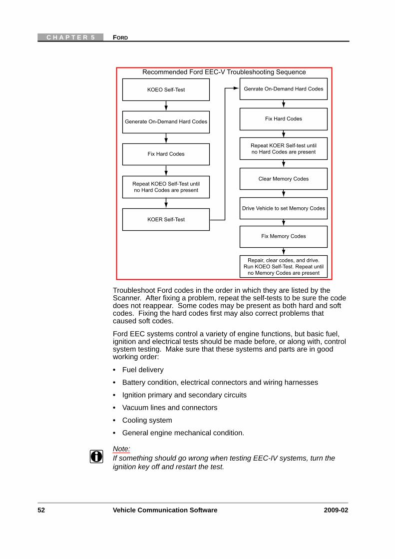
52 Vehicle Communication Software 2009-02
C H A P T E R 5 FORD
Troubleshoot Ford codes in the order in which they are listed by the Scanner. After fixing a problem, repeat the self-tests to be sure the code does not reappear. Some codes may be present as both hard and soft codes. Fixing the hard codes first may also correct problems that caused soft codes.
Ford EEC systems control a variety of engine functions, but basic fuel, ignition and electrical tests should be made before, or along with, control system testing. Make sure that these systems and parts are in good working order:
• Fuel delivery
• Battery condition, electrical connectors and wiring harnesses
• Ignition primary and secondary circuits
• Vacuum lines and connectors
• Cooling system
• General engine mechanical condition.
Note:i If something should go wrong when testing EEC-IV systems, turn the
ignition key off and restart the test.
Repair, clear codes, and drive.Run KOEO Self-Test. Repeat until
no Memory Codes are present
Fix Memory Codes
Drive Vehicle to set Memory Codes
Clear Memory Codes
Repeat KOER Self-test untilno Hard Codes are present
Genrate On-Demand Hard Codes
KOER Self-Test
Repeat KOEO Self-Test untilno Hard Codes are present
Fix Hard Codes
Generate On-Demand Hard Codes
KOEO Self-Test
Recommended Ford EEC-V Troubleshooting Sequence
Fix Hard Codes

53
REVIEW MOVIE
Note:i If something should go wrong when testing EEC-V systems, turn the
ignition key off, wait at least 10 seconds before turning the key on again and restart the test.
5.8 Review Movie
5.8.1 Review Movie “Exit” Menu
8.1. Review Movie"Exit" Menu
5. Main Menu
8. Review Movie
Y
Review Recorded Data
N
N
Resume
N
Y
Y
N
N
Y
Print ScreenPrint Frame
LED Menu
8.1. Review Movie Exit Menu
8. Review Movie
Assign LED Functions
Print Out of Screenor Frame
5. Main Menu
YFix line 1Fix/Release Lines
54 Vehicle Communication Software 2009-02
C H A P T E R 5 FORD
5.9 Functional Tests
5.9.1 Functional Tests — EEC-IVThe FUNCTIONAL TESTS mode for EEC-IV vehicles lets the operator perform all engine operating (functional) tests programmed into the power-train control module (PCM). The ignition key should be OFF when FUNCTIONAL TESTS is selected.
Computed Timing
Note:i Before entering this test, connect a timing light or a magnetic timing
meter to the engine.
The COMPUTED TIMING test allows the checking of ignition timing with the engine running at a controlled idle speed. It also verifies the ability of the ECU to advance and retard timing. The ECU provides a fixed base timing specification in this test mode.
Wiggle Tests (Engine Off) & (Engine Running)
The WIGGLE tests put the system into a program that will record intermittent service codes that occur as various engine sensors, actuators and wiring connectors are wiggled or tapped with the engine off or running or during a test drive.
Output State Test
Note:i The engine must be shut down before selecting OUTPUT STATE test.
The OUTPUT STATE test allows the switching of the ECU signals to the engine actuators on and off so that they can be tested with a voltmeter.
Cylinder Balance (SFI Engines)
The CYLINDER BALANCE test allows the checking of the operation of individual fuel injectors for sequential electronic fuel injection (SFI) systems. The ECU disables each injector individually and compares the engine speed drop from cylinder to cylinder. At the end of the test stages, the Scanner will display the results recorded by the ECU.
Idle Speed Adjustment
The Scanner can be used to assist in idle speed adjustment on certain engines. Before adjusting idle speed, make sure that the throttle body and the idle speed control (ISC) devices are clean and that the throttle linkage is not sticking or binding.
Caution:ä If any service codes other than 11 — NO FAULTS PRESENT are
displayed after the engine-running test, troubleshoot and correct those problems before proceeding with idle adjustment.
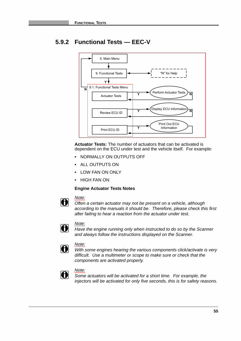
55
FUNCTIONAL TESTS
5.9.2 Functional Tests — EEC-V
Actuator Tests: The number of actuators that can be activated is dependent on the ECU under test and the vehicle itself. For example:
• NORMALLY ON OUTPUTS OFF
• ALL OUTPUTS ON
• LOW FAN ON ONLY
• HIGH FAN ON
Engine Actuator Tests Notes
Note:i Often a certain actuator may not be present on a vehicle, although
according to the manuals it should be. Therefore, please check this first after failing to hear a reaction from the actuator under test.
Note:i Have the engine running only when instructed to do so by the Scanner
and always follow the instructions displayed on the Scanner.
Note:i With some engines hearing the various components click/activate is very
difficult. Use a multimeter or scope to make sure or check that the components are activated properly.
Note:i Some actuators will be activated for a short time. For example, the
injectors will be activated for only five seconds, this is for safety reasons.
Y
N 9.1. Functional Tests Menu
5. Main Menu
"N" for Help9. Functional Tests
YReview ECU IDDisplay ECU Information N
YPrint ECU ID
Print Out ECUInformation
YActuator TestsPerform Actuator Tests N
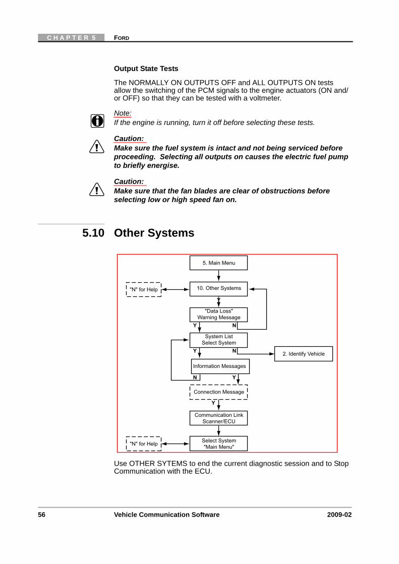
56 Vehicle Communication Software 2009-02
C H A P T E R 5 FORD
Output State Tests
The NORMALLY ON OUTPUTS OFF and ALL OUTPUTS ON tests allow the switching of the PCM signals to the engine actuators (ON and/or OFF) so that they can be tested with a voltmeter.
Note:i If the engine is running, turn it off before selecting these tests.
Caution:ä Make sure the fuel system is intact and not being serviced before
proceeding. Selecting all outputs on causes the electric fuel pump to briefly energise.
Caution:ä Make sure that the fan blades are clear of obstructions before
selecting low or high speed fan on.
5.10 Other Systems
Use OTHER SYTEMS to end the current diagnostic session and to Stop Communication with the ECU.
System ListSelect System
Connection Message
Select System"Main Menu"
2. Identify Vehicle
5. Main Menu
Y N
Y
10. Other Systems
"Data Loss"Warning Message
Y N
"N" for Help
"N" for Help
Information Messages
Y
Communication LinkScanner/ECU
N Y
57
OTHER SYSTEMS
Caution:ä The ABS System or ECU can be damaged or disabled if the
Scanner is disconnected before communication has properly stopped. Always return to the Main Menu and select “Other Systems” before disconnecting the Scanner.
5.10.1 Super Star II SelectionScroll to the SUPER STAR II selection and press Y. The Scanner will display the Super Star II operating screen.
Scanner Controls:
The Scanner operates as explained below in the Super Star Mode:
Thumbwheel/Arrow Keys
Scroll the thumbwheel (or use the Arrow Keys) to move the cursor and select any of the three functions on the screen.
Y Button
Press Y to change the setting of the function indicated by the cursor.
N Button
Press N to exit from the Super Star II mode back to the starting test selection screen.
LED Indicators
The left-hand LED works as a self-test output (STO) indicator. The LED will light each time the STO voltage switches low. Fast codes cause the LED to flicker or flash briefly. Slow codes cause the LED to light in even pulses, which indicate the code digits.
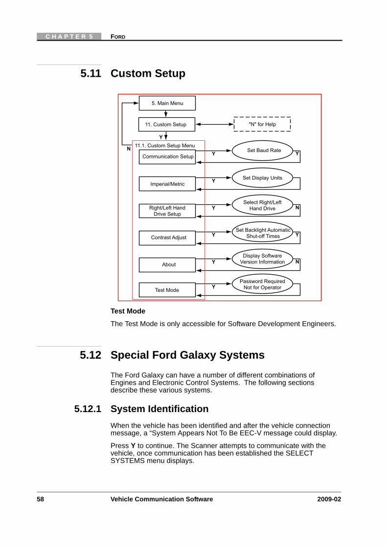
58 Vehicle Communication Software 2009-02
C H A P T E R 5 FORD
5.11 Custom Setup
Test Mode
The Test Mode is only accessible for Software Development Engineers.
5.12 Special Ford Galaxy SystemsThe Ford Galaxy can have a number of different combinations of Engines and Electronic Control Systems. The following sections describe these various systems.
5.12.1 System IdentificationWhen the vehicle has been identified and after the vehicle connection message, a “System Appears Not To Be EEC-V message could display.
Press Y to continue. The Scanner attempts to communicate with the vehicle, once communication has been established the SELECT SYSTEMS menu displays.
Y
N 11.1. Custom Setup Menu
5. Main Menu
"N" for Help11. Custom Setup
YCommunication SetupSet Baud Rate Y
YImperial/MetricSet Display Units
YAbout
Display SoftwareVersion Information N
YContrast AdjustSet Backlight Automatic
Shut-off Times Y
YRight/Left HandDrive Setup
Select Right/LeftHand Drive N
YTest Mode
Password RequiredNot for Operator
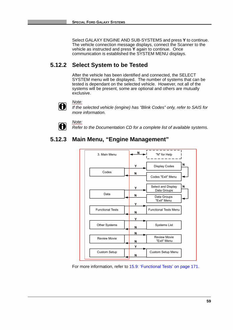
59
SPECIAL FORD GALAXY SYSTEMS
Select GALAXY ENGINE AND SUB-SYSTEMS and press Y to continue. The vehicle connection message displays, connect the Scanner to the vehicle as instructed and press Y again to continue. Once communication is established the SYSTEM MENU displays.
5.12.2 Select System to be TestedAfter the vehicle has been identified and connected, the SELECT SYSTEM menu will be displayed. The number of systems that can be tested is dependant on the selected vehicle. However, not all of the systems will be present, some are optional and others are mutually exclusive.
Note:i If the selected vehicle (engine) has “Blink Codes” only, refer to SAIS for
more information.
Note:i Refer to the Documentation CD for a complete list of available systems.
5.12.3 Main Menu, “Engine Management”
For more information, refer to 15.9: ‘Functional Tests’ on page 171.
N
N
N
Y
N
Y
N
Y
Review Movie
Functional Tests
Other Systems
Custom Setup
Review Movie"Exit" Menu
Functional Tests Menu
Systems List
Custom Setup Menu
N "N" for Help3. Main Menu
Display Codes
Codes
Y N
Codes "Exit" MenuN
Select and DisplayData Groups
Data
Y N
Data Groups"Exit" Menu
N
60 Vehicle Communication Software 2009-02
C H A P T E R 5 FORD
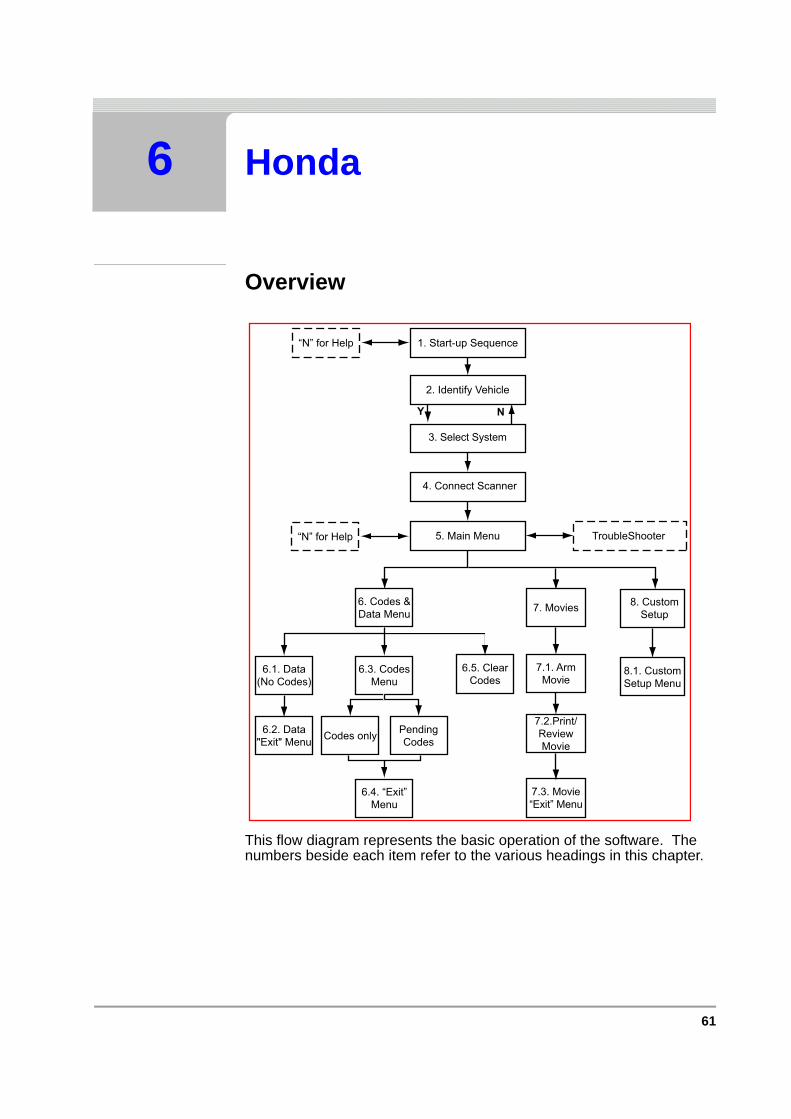
61
6 Honda
Overview
This flow diagram represents the basic operation of the software. The numbers beside each item refer to the various headings in this chapter.
1. Start-up Sequence“N” for Help
2. Identify Vehicle
4. Connect Scanner
5. Main Menu TroubleShooter“N” for Help
Y N
3. Select System
6.5. ClearCodes
PendingCodes
6.4. “Exit”Menu
8. CustomSetup
8.1. CustomSetup Menu
7. Movies
7.1. ArmMovie
7.2.Print/ReviewMovie
7.3. Movie“Exit” Menu
6.3. CodesMenu
Codes only
6. Codes &Data Menu
6.1. Data(No Codes)
6.2. Data"Exit" Menu

62 Vehicle Communication Software 2009-02
C H A P T E R 6 HONDA
6.1 Start-up Sequence
Select
• “Honda/Nissan/Toyota”
Select Make
• Honda
6.2 Identify Vehicle
Y
N
Display Test and Copyright Notice
Select"Honda/Nissan/Toyota"
2. Identify Vehicle
Select MakeN
1. Start-up Sequence
2. Identify Vehicle
Select Model Year
Select Model Type
Select Engine Type
Select Options
3. Select System
Y N
Y
Y
Y N
Y N
N
N

63
SELECT SYSTEM TO BE TESTED
6.3 Select System to be Tested
6.3.1 System ListThe system list will remain active until a new vehicle is selected. Scroll to the selected the system to be tested and press Y to confirm.
Note:i Refer to the Documentation CD for the complete list of Systems
available.
Caution:ä The ABS System or ECU can be damaged or disabled if the
Scanner is disconnected before communication has properly stopped. Always return to the “Select System” menu before disconnecting the Scanner.
6.4 Connect Scanner
System List
2. Identify Vehicle
5. Main Menu
4. Connect Scanner
3. Select System
Y N
Y
System List
2. Identify Vehicle
5. Main Menu
Communication:Scanner/ECU
Y N
Connection MessagesConnect Scanner
Y
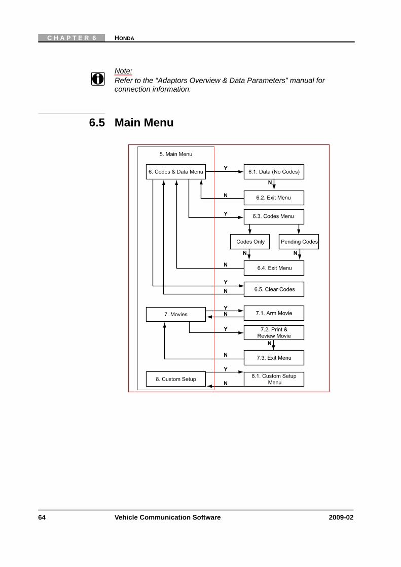
64 Vehicle Communication Software 2009-02
C H A P T E R 6 HONDA
Note:i Refer to the “Adaptors Overview & Data Parameters” manual for
connection information.
6.5 Main Menu
7.1. Arm Movie7. Movies NY
N
Y
N
Y
7.3. Exit Menu
8. Custom Setup
7.2. Print &Review Movie
8.1. Custom SetupMenu
5. Main Menu
6.1. Data (No Codes)6. Codes & Data Menu Y
N
N
N
N
6.3. Codes Menu
6.4. Exit Menu
6.2. Exit Menu
Codes Only Pending Codes
N N
Y
6.5. Clear CodesYN

65
CODES & DATA MENU
6.6 Codes & Data Menu
6.6.1 Data (No Codes)Displays live data parameters, scroll for complete list.
Press N for the Data (No Codes) “Exit” Menu.
6.1. Data (No Codes)
6. Codes & Data Menu
Y
N
N
N
6.3. Codes Menu
6.4. Exit Menu
6.2. Exit Menu
Codes Only Pending Codes
N N
Y
6.5. Clear CodesYN
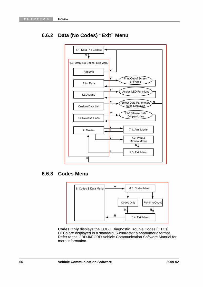
66 Vehicle Communication Software 2009-02
C H A P T E R 6 HONDA
6.6.2 Data (No Codes) “Exit” Menu
6.6.3 Codes Menu
Codes Only displays the EOBD Diagnostic Trouble Codes (DTCs). DTCs are displayed in a standard, 5-character alphanumeric format. Refer to the OBD-II/EOBD Vehicle Communication Software Manual for more information.
6.2. Data (No Codes) Exit Menu
Resume
Y
N
N
6.1. Data (No Codes)
Y
N
7.1. Arm Movie7. Movies NY
N
Y
7.3. Exit Menu
7.2. Print &Review Movie
N
Print Data
LED Menu
Custom Data List
Fix/Release Lines
Select Data Parametersto be Displayed
Fix/Release DataDislpay Lines
Assign LED Functions
Print Out of Screenor Frame
Y
Y
Y
6. Codes & Data Menu
N
6.3. Codes Menu
6.4. Exit Menu
Codes Only Pending Codes
N N
Y
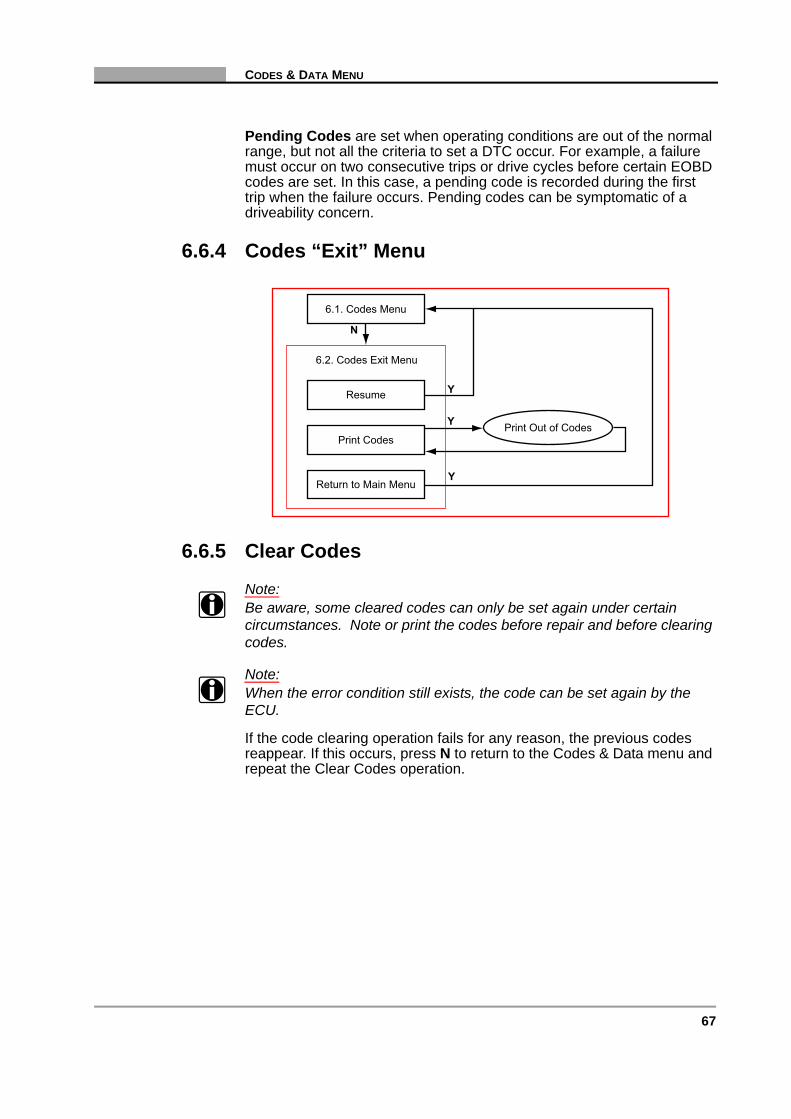
67
CODES & DATA MENU
Pending Codes are set when operating conditions are out of the normal range, but not all the criteria to set a DTC occur. For example, a failure must occur on two consecutive trips or drive cycles before certain EOBD codes are set. In this case, a pending code is recorded during the first trip when the failure occurs. Pending codes can be symptomatic of a driveability concern.
6.6.4 Codes “Exit” Menu
6.6.5 Clear Codes
Note:i Be aware, some cleared codes can only be set again under certain
circumstances. Note or print the codes before repair and before clearing codes.
Note:i When the error condition still exists, the code can be set again by the
ECU.
If the code clearing operation fails for any reason, the previous codes reappear. If this occurs, press N to return to the Codes & Data menu and repeat the Clear Codes operation.
6.2. Codes Exit Menu
Resume
Y
N
6.1. Codes Menu
Y
Print Codes
Return to Main Menu
Print Out of Codes
Y

68 Vehicle Communication Software 2009-02
C H A P T E R 6 HONDA
6.7 Movies
6.7.1 Print/Review Movies “Exit” Menu
N
5. Main Menu
7.1. Arm Movie
7. Movies
NY
7.3. Exit Menu
7.2. Print &Review Movie
N
N
Y
7.3. Print/Review Movie Exit Menu
Resume
Y
N
7.2. Print/Review Movie
Print ScreenPrint Frame
Fix/Release Lines
Fix/Release DataDislpay Lines
Print Out of Screenor Frame
Y
5. Main MenuN

69
CUSTOM SETUP
6.8 Custom Setup
6.9 Anti-lock Brakes SystemsCode Functions Menu
The following menu items are available:
• SCS Mode, (Service Check Signal) used for checking the ABS/TCS flash diagnostic trouble codes. The stored codes will flash on the ABS/TCS lamp. If there are no codes present the lamp will switch off for approximately 3 seconds and then stay on continuously. Refer to manufacturers documentation for more information.
• Clear Codes, used to clear codes. Carefully follow all instructions displayed.
• Code Descriptions, displays the ABS code and a brief description.
6.10 Airbag SystemsCode Functions Menu
The following menu items are available:
8.1 Custom Setup Menu
Y
N
5. Main Menu
Communication Setup
Imperial/Metric
Contrast AdjustSet Backlight Automatic
Shut-off Time
Set Display Units
Set Baud Rate
Y
Y
8. Custom Setup
Y
Y
Y
N
70 Vehicle Communication Software 2009-02
C H A P T E R 6 HONDA
• SCS Mode, (Service Check Signal) used for checking the SRS flash diagnostic trouble codes. The stored codes will flash on the SRS lamp. If there are no codes present the lamp will switch off once and then stay on continuously. Refer to manufacturers documentation for more information.
• Clear Codes, used to clear codes. Carefully follow all instructions displayed.
• Code Descriptions, displays the Airbag code and a brief description.
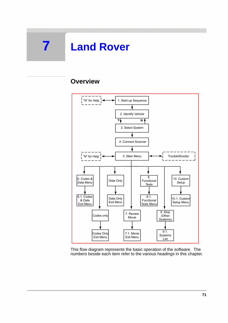
71
7 Land Rover
Overview
This flow diagram represents the basic operation of the software. The numbers beside each item refer to the various headings in this chapter.
1. Start-up Sequence“N” for Help
2. Identify Vehicle
4. Connect Scanner
5. Main Menu TroubleShooter“N” for Help
Y N
3. Select System
10. CustomSetup
10.1. CustomSetup Menu
7. ReviewMovie
9. Stop(Other
Systems)
9.1.Systems
List
7.1. MovieExit Menu
Codes only
6. Codes &Data Menu Data Only
Data OnlyExit Menu
6.1. Codes& Data
Exit Menu
Codes OnlyExit Menu
8.Functional
Tests
8.1.FunctionalTests Menu

72 Vehicle Communication Software 2009-02
C H A P T E R 7 LAND ROVER
7.1 Start-up Sequence
Select Make
The following makes are available:
• LAND ROVER
Select L/R Drive
The correct connector location information displayed is dependent on this selection:
• Scroll to CUSTOM SETUP.
• Select LEFT/RIGHT HAND DRIVE SETUP and press Y to continue. Select LEFT or RIGHT HAND DRIVE, press Y.
• Press N the CUSTOM SETUP menu will be redisplayed.
• Press N again to continue to the Vehicle Identification.
Display Test &Copyright Notice
“N” for Help Select Brand
Vehicle Systems Training Mode(Demonstration)
Identify Vehicle
Scroll and Select
Y Y
Y
Y
N
Custom SetupSelect L/R Drive

73
IDENTIFY VEHICLE
7.2 Identify Vehicle
7.2.1 System ID Mode, (Expert Mode)Use this mode if communication problem arise or if the vehicle has an unknown ECU type.
1. Select a system group from the list. Only fitted systems groups (engines, lights, seat, etc.) will be displayed.
2. After selecting the system group, select the system to be tested.
3. Connect the scanner and proceed testing.
1. Start-up Sequence
2. Identify Vehicle
Select Model Year
Select Model Type
Select Engine Type
Select Options
3. Select System
Y N
Y
Y
Y N
Y N
N
N
System List
Connect Scanner
Instruction Messages
System ID Mode
2. Identify Vehicle
5. Main Menu
Y N
Y
Y
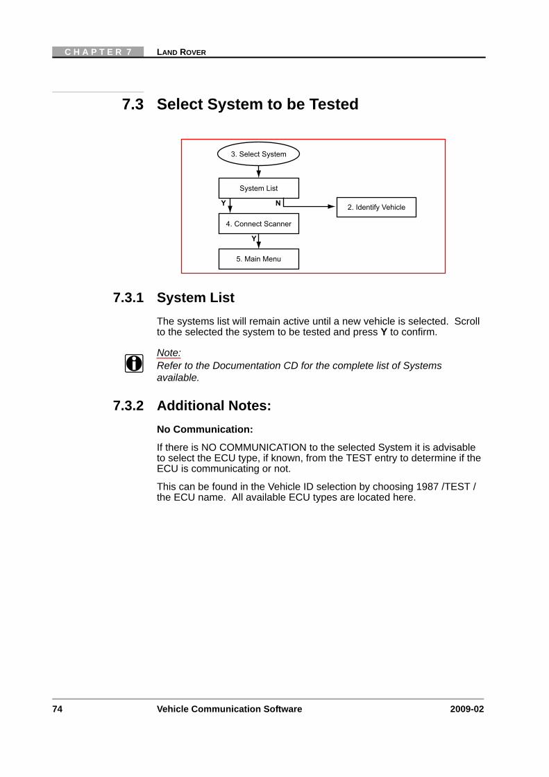
74 Vehicle Communication Software 2009-02
C H A P T E R 7 LAND ROVER
7.3 Select System to be Tested
7.3.1 System ListThe systems list will remain active until a new vehicle is selected. Scroll to the selected the system to be tested and press Y to confirm.
Note:i Refer to the Documentation CD for the complete list of Systems
available.
7.3.2 Additional Notes:No Communication:
If there is NO COMMUNICATION to the selected System it is advisable to select the ECU type, if known, from the TEST entry to determine if the ECU is communicating or not.
This can be found in the Vehicle ID selection by choosing 1987 /TEST / the ECU name. All available ECU types are located here.
System List
2. Identify Vehicle
5. Main Menu
4. Connect Scanner
3. Select System
Y N
Y
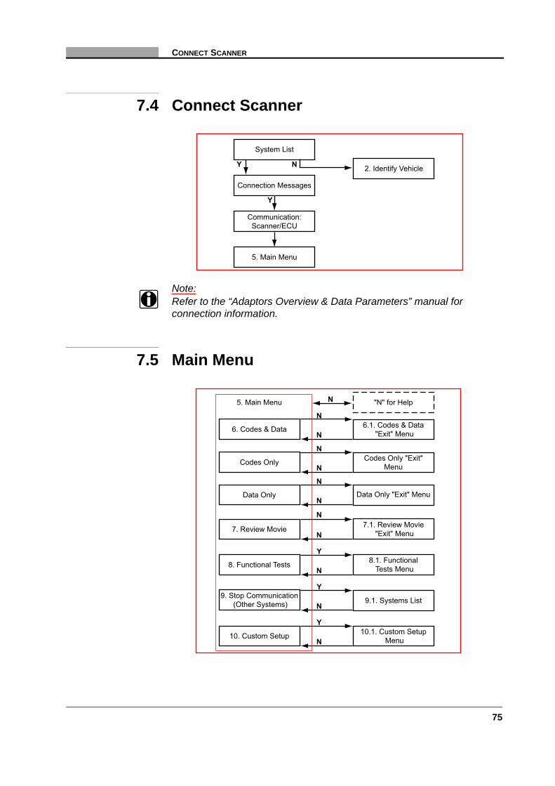
75
CONNECT SCANNER
7.4 Connect Scanner
Note:i Refer to the “Adaptors Overview & Data Parameters” manual for
connection information.
7.5 Main Menu
System List
2. Identify Vehicle
5. Main Menu
Communication:Scanner/ECU
Y N
Connection Messages
Y
6.1. Codes & Data"Exit" Menu6. Codes & Data
N
N
N
N
N
N
Y
N
Y
N
Y
7. Review Movie
8. Functional Tests
9. Stop Communication(Other Systems)
10. Custom Setup
"N" for Help5. Main Menu
7.1. Review Movie"Exit" Menu
8.1. FunctionalTests Menu
9.1. Systems List
10.1. Custom SetupMenu
Codes Only "Exit"MenuCodes Only
N
N
Data Only "Exit" MenuData OnlyN
N

76 Vehicle Communication Software 2009-02
C H A P T E R 7 LAND ROVER
7.6 Codes & Data
7.6.1 Data (No Codes)Displays live data parameters, scroll for complete list.
Press N for the Data (No Codes) “Exit Menu.
7.6.2 Codes OnlyDisplays the Diagnostic Trouble Codes (DTCs), scroll for complete list.
Press N for the Codes Only “Exit Menu.
"N" for Help2. Codes & Data
Communication LinkScanner/ECU
Holding Data Frames
Y
Y
N
NY N
Codes/Data Lists:Codes, Data Parameters
6.1. Codes & Data"Exit" Menu
Y
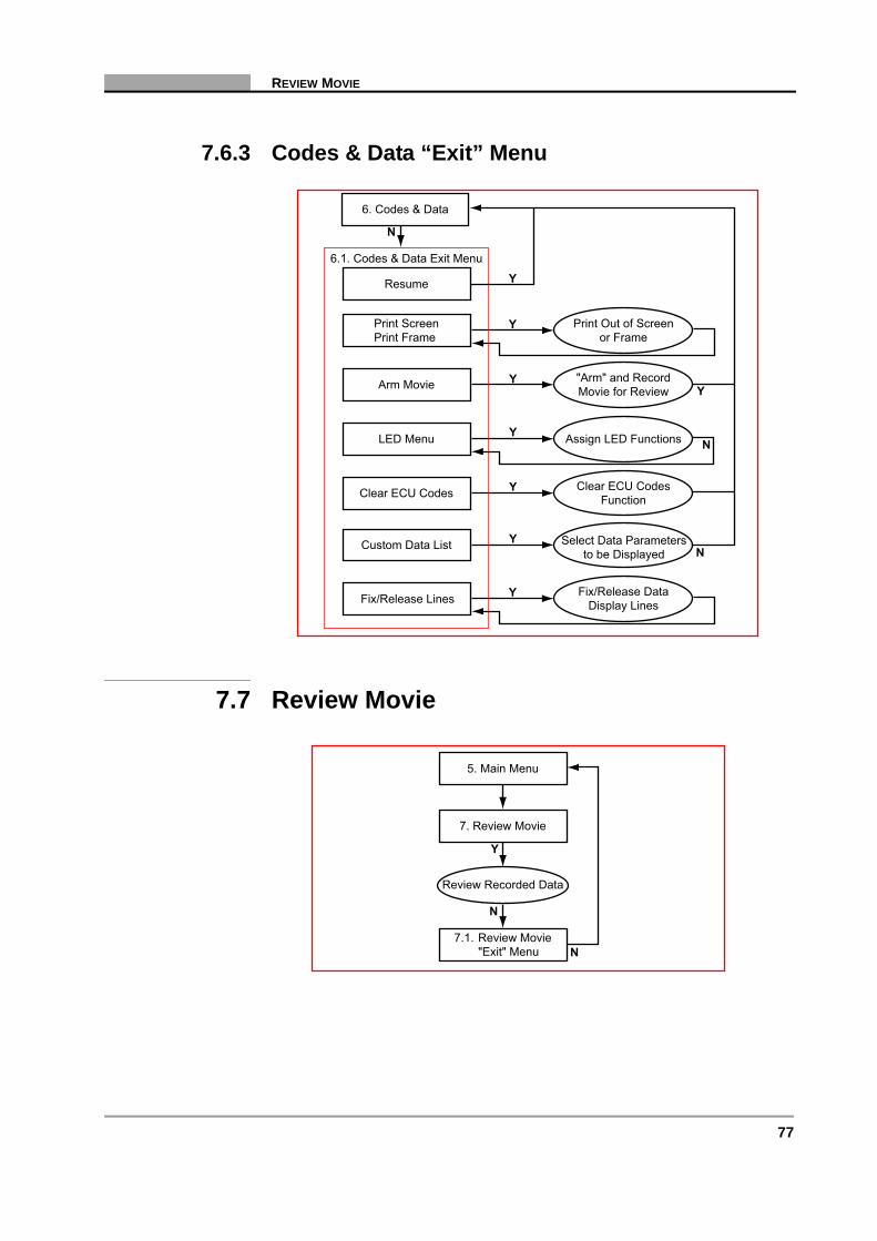
77
REVIEW MOVIE
7.6.3 Codes & Data “Exit” Menu
7.7 Review Movie
Resume
N
Y
Y
N
Y
N
Y
Y
Print ScreenPrint Frame
Arm Movie
LED Menu
Clear ECU Codes
6.1. Codes & Data Exit Menu
6. Codes & Data
Custom Data List Select Data Parametersto be Displayed
Clear ECU CodesFunction
Assign LED Functions
"Arm" and RecordMovie for Review
Print Out of Screenor Frame
Y
Y
YFix/Release Lines Fix/Release DataDisplay Lines
7.1. Review Movie"Exit" Menu
5. Main Menu
7. Review Movie
Y
Review Recorded Data
N
N
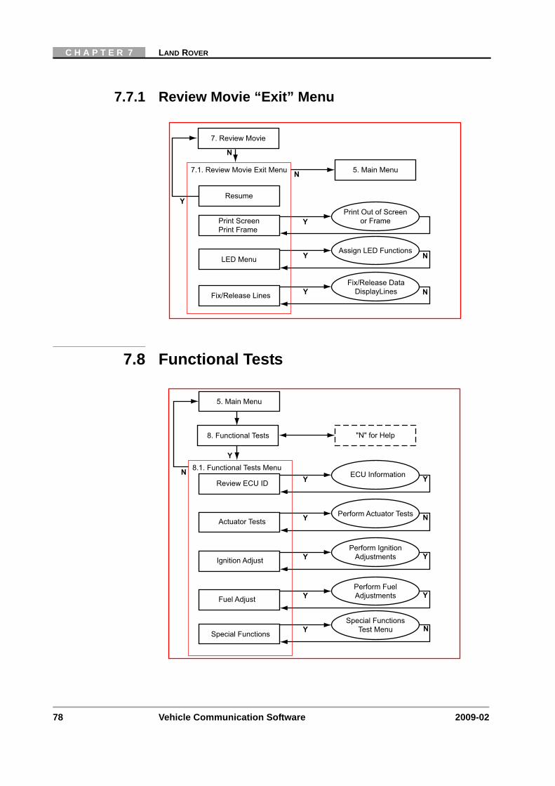
78 Vehicle Communication Software 2009-02
C H A P T E R 7 LAND ROVER
7.7.1 Review Movie “Exit” Menu
7.8 Functional Tests
Resume
N
Y
Y
N
N
Y
Print ScreenPrint Frame
LED Menu
7.1. Review Movie Exit Menu
7. Review Movie
Assign LED Functions
Print Out of Screenor Frame
5. Main Menu
NYFix/Release Lines
Fix/Release DataDisplayLines
Y
N 8.1. Functional Tests Menu
5. Main Menu
"N" for Help8. Functional Tests
YReview ECU IDECU Information Y
YSpecial Functions
Special FunctionsTest Menu
YFuel Adjust
Perform FuelAdjustments Y
YIgnition Adjust
Perform IgnitionAdjustments Y
YActuator TestsPerform Actuator Tests N
N

79
STOP COMMUNICATION, (OTHER SYSTEMS)
Actuator Tests: The number of actuators that can be activated is dependent on the ECU under test and the vehicle itself. For example:
• RPM Signal
• Purge Control Solenoid
• Main Relay
• Fuel Pump Relay
• Malfunction Indicator Light
• Engine Fan Relay
• Cruise Lamp
• O2 Sensor Heater Relay
• Injectors
Special Functions, (Sub-menu), Example:
• Ignition Coil 1 Charge Time
• Ignition Coil 2 Charge Time
7.9 Stop Communication, (Other Systems)
Use STOP COMMUNICATION (OTHER SYSTEMS) to end the current diagnostic session and to Stop Communication with the ECU.
System ListSelect System
Connection Message
Select System"Main Menu"
2. Identify Vehicle
5. Main Menu
Y N
Y
9. Stop Communication(Other Systems)
"Data Loss"Warning Message
Y N
"N" for Help
"N" for Help
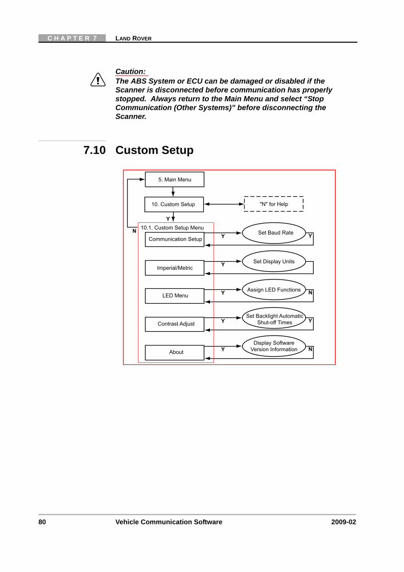
80 Vehicle Communication Software 2009-02
C H A P T E R 7 LAND ROVER
Caution:ä The ABS System or ECU can be damaged or disabled if the
Scanner is disconnected before communication has properly stopped. Always return to the Main Menu and select “Stop Communication (Other Systems)” before disconnecting the Scanner.
7.10 Custom Setup
Y
N 10.1. Custom Setup Menu
5. Main Menu
"N" for Help10. Custom Setup
YCommunication SetupSet Baud Rate Y
YImperial/MetricSet Display Units
YAbout
Display SoftwareVersion Information N
YContrast AdjustSet Backlight Automatic
Shut-off Times Y
YLED MenuAssign LED Functions N
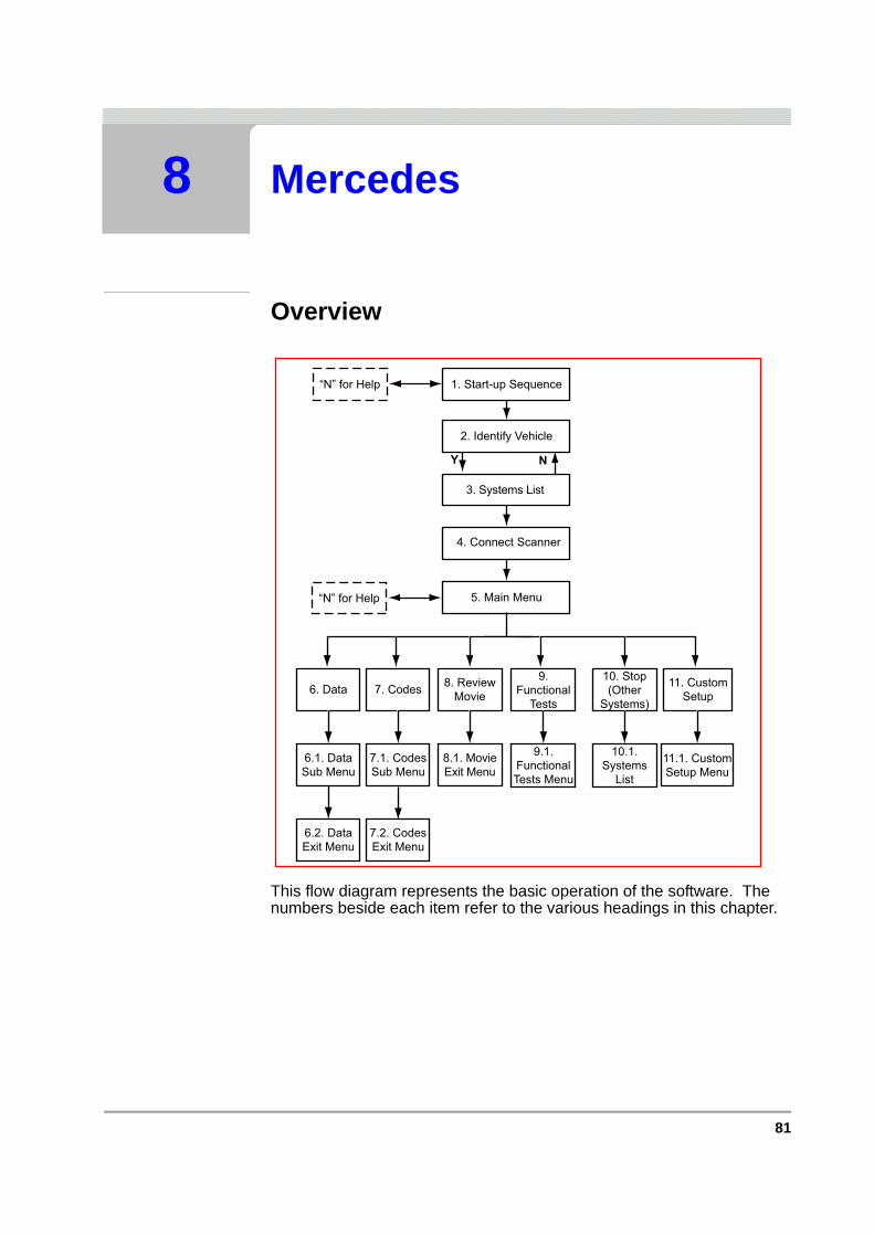
81
8 Mercedes
Overview
This flow diagram represents the basic operation of the software. The numbers beside each item refer to the various headings in this chapter.
1. Start-up Sequence“N” for Help
2. Identify Vehicle
4. Connect Scanner
5. Main Menu“N” for Help
Y N
3. Systems List
11. CustomSetup
11.1. CustomSetup Menu
8. ReviewMovie
10. Stop(Other
Systems)
10.1.Systems
List
8.1. MovieExit Menu
6. Data
6.1. DataSub Menu
9.Functional
Tests
9.1.FunctionalTests Menu
6.2. DataExit Menu
7. Codes
7.1. CodesSub Menu
7.2. CodesExit Menu

82 Vehicle Communication Software 2009-02
C H A P T E R 8 MERCEDES
8.1 Start-up Sequence
Select Make
Select:
• Mercedes
Select L/R Drive
The correct connector location information displayed is dependent on this selection:
• Scroll to CUSTOM SETUP.
• Select LEFT/RIGHT HAND and press Y. Press Y to select STEERING WHEEL [LEFT or RIGHT HAND].
• Press N.
• Press N again to continue to the Vehicle Identification.
Display Test &Copyright Notice
“N” for Help Select Make
Vehicle Systems Training Mode
Identify Vehicle
Scroll and Select
Y Y
Y
Y
N
Custom Setup
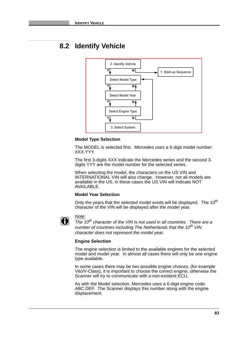
83
IDENTIFY VEHICLE
8.2 Identify Vehicle
Model Type Selection
The MODEL is selected first. Mercedes uses a 6-digit model number: XXX.YYY.
The first 3-digits XXX indicate the Mercedes series and the second 3-digits YYY are the model number for the selected series.
When selecting the model, the characters on the US VIN and INTERNATIONAL VIN will also change. However, not all models are available in the US, in these cases the US VIN will indicate NOT AVAILABLE.
Model Year Selection
Only the years that the selected model exists will be displayed. The 10th character of the VIN will be displayed after the model year.
Note:i The 10th character of the VIN is not used in all countries. There are a
number of countries including The Netherlands that the 10th VIN character does not represent the model year.
Engine Selection
The engine selection is limited to the available engines for the selected model and model year. In almost all cases there will only be one engine type available.
In some cases there may be two possible engine choices, (for example Vito/V-Class), it is important to choose the correct engine, otherwise the Scanner will try to communicate with a non-existent ECU.
As with the Model selection, Mercedes uses a 6-digit engine code: ABC.DEF. The Scanner displays this number along with the engine displacement.
1. Start-up Sequence
2. Identify Vehicle
Select Model Type
Select Model Year
Select Engine Type
3. Select System
Y N
Y
Y
Y N
N
N

84 Vehicle Communication Software 2009-02
C H A P T E R 8 MERCEDES
A code is displayed after the engine displacement indicating how the engine is mounted, the type of engine and the number of cylinders.
For example:
- L-V8: Engine mounted in line, V-type, 8 cylinders- T-L4: Engine mounted transversely, Line-engine, 4 cylinders
It maybe sometimes difficult to find the correct engine identification. It is recommended to try to communicate with the first engine type, if that fails then try selecting the other engine type.
When the vehicle has been completely selected, an overview of the selection will be displayed. The operator can accept this selection or return to the vehicle selection and select a different vehicle.
8.2.1 System ID ModeUse this mode if communication problem arise or if the vehicle has an unknown ECU type.
1. Select a system group from the list. Only fitted systems groups (engines, lights, seat, etc.) will be displayed.
2. After selecting the system group, select the system to be tested.
3. Connect the scanner and proceed testing.
System List
Connect Scanner
Instruction Messages
System ID Mode
2. Identify Vehicle
5. Main Menu
Y N
Y
Y
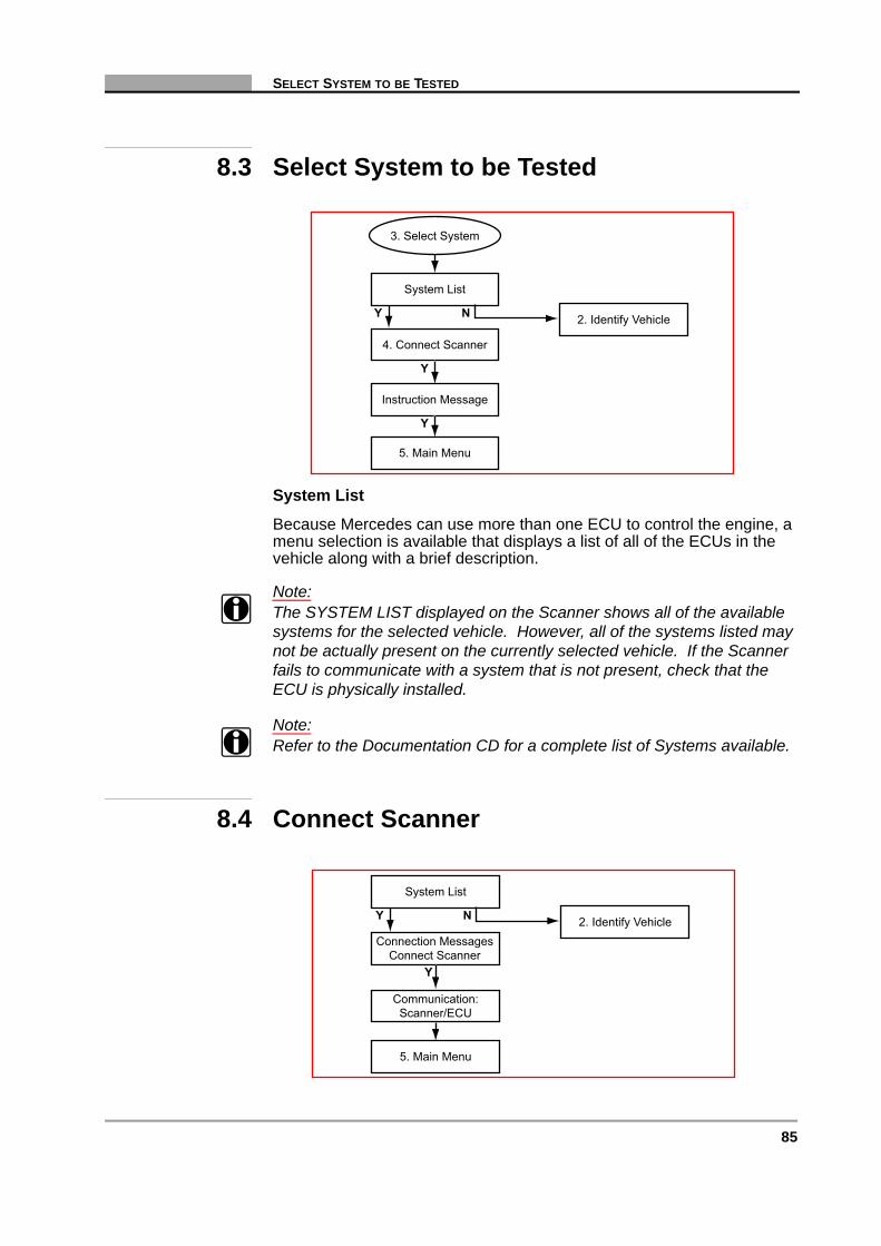
85
SELECT SYSTEM TO BE TESTED
8.3 Select System to be Tested
System List
Because Mercedes can use more than one ECU to control the engine, a menu selection is available that displays a list of all of the ECUs in the vehicle along with a brief description.
Note:i The SYSTEM LIST displayed on the Scanner shows all of the available
systems for the selected vehicle. However, all of the systems listed may not be actually present on the currently selected vehicle. If the Scanner fails to communicate with a system that is not present, check that the ECU is physically installed.
Note:i Refer to the Documentation CD for a complete list of Systems available.
8.4 Connect Scanner
System List
2. Identify Vehicle
Instruction Message
4. Connect Scanner
3. Select System
Y N
Y
5. Main Menu
Y
System List
2. Identify Vehicle
5. Main Menu
Communication:Scanner/ECU
Y N
Connection MessagesConnect Scanner
Y
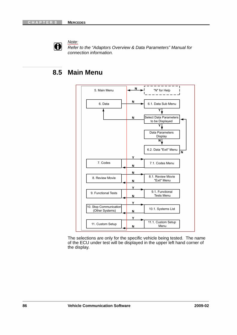
86 Vehicle Communication Software 2009-02
C H A P T E R 8 MERCEDES
Note:i Refer to the “Adaptors Overview & Data Parameters” Manual for
connection information.
8.5 Main Menu
The selections are only for the specific vehicle being tested. The name of the ECU under test will be displayed in the upper left hand corner of the display.
7.1. Codes Menu7. CodesN
Y
N
N
N
Y
N
Y
N
Y
8. Review Movie
9. Functional Tests
10. Stop Communication(Other Systems)
11. Custom Setup
8.1. Review Movie"Exit" Menu
9.1. FunctionalTests Menu
10.1. Systems List
11.1. Custom SetupMenu
N "N" for Help5. Main Menu
6.1. Data Sub Menu6. Data N
N
N
Y
N
Y
Select Data Parametersto be Displayed
Data ParametersDisplay
6.2. Data "Exit" Menu
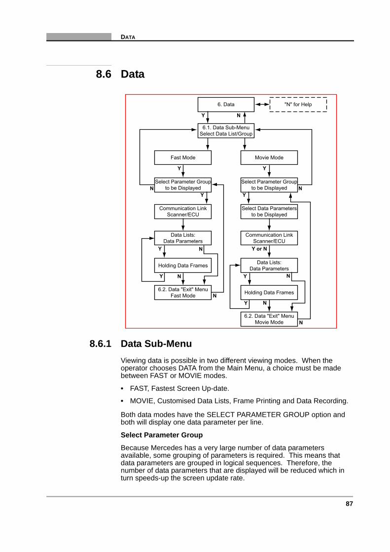
87
DATA
8.6 Data
8.6.1 Data Sub-MenuViewing data is possible in two different viewing modes. When the operator chooses DATA from the Main Menu, a choice must be made between FAST or MOVIE modes.
• FAST, Fastest Screen Up-date.
• MOVIE, Customised Data Lists, Frame Printing and Data Recording.
Both data modes have the SELECT PARAMETER GROUP option and both will display one data parameter per line.
Select Parameter Group
Because Mercedes has a very large number of data parameters available, some grouping of parameters is required. This means that data parameters are grouped in logical sequences. Therefore, the number of data parameters that are displayed will be reduced which in turn speeds-up the screen update rate.
"N" for Help
6.1. Data Sub-MenuSelect Data List/Group
6. Data
Y N
N
N
Y
Select Parameter Groupto be Displayed
Data Lists:Data Parameters
6.2. Data "Exit" MenuFast Mode
Communication LinkScanner/ECU
Holding Data Frames
Fast Mode
Y
Y
Y
N
N
Y or N
Y
Select Parameter Groupto be Displayed
Data Lists:Data Parameters
6.2. Data "Exit" MenuMovie Mode
Communication LinkScanner/ECU
Holding Data Frames
Movie Mode
Select Data Parametersto be Displayed
Y
Y
NY
N
N
N
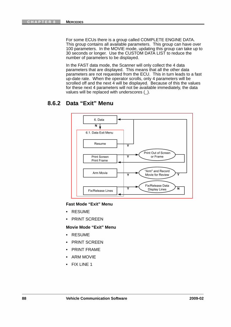
88 Vehicle Communication Software 2009-02
C H A P T E R 8 MERCEDES
For some ECUs there is a group called COMPLETE ENGINE DATA. This group contains all available parameters. This group can have over 100 parameters. In the MOVIE mode, updating this group can take up to 30 seconds or longer. Use the CUSTOM DATA LIST to reduce the number of parameters to be displayed.
In the FAST data mode, the Scanner will only collect the 4 data parameters that are displayed. This means that all the other data parameters are not requested from the ECU. This in turn leads to a fast up-date rate. When the operator scrolls, only 4 parameters will be scrolled off and the next 4 will be displayed. Because of this the values for these next 4 parameters will not be available immediately, the data values will be replaced with underscores (_).
8.6.2 Data “Exit” Menu
Fast Mode “Exit” Menu
• RESUME
• PRINT SCREEN
Movie Mode “Exit” Menu
• RESUME
• PRINT SCREEN
• PRINT FRAME
• ARM MOVIE
• FIX LINE 1
Resume
N
Y
Y
N
Y
Y
Print ScreenPrint Frame
Arm Movie
Fix/Release Lines
6.1. Data Exit Menu
6. Data
Fix/Release DataDisplay Lines
"Arm" and RecordMovie for Review
Print Out of Screenor Frame
Y
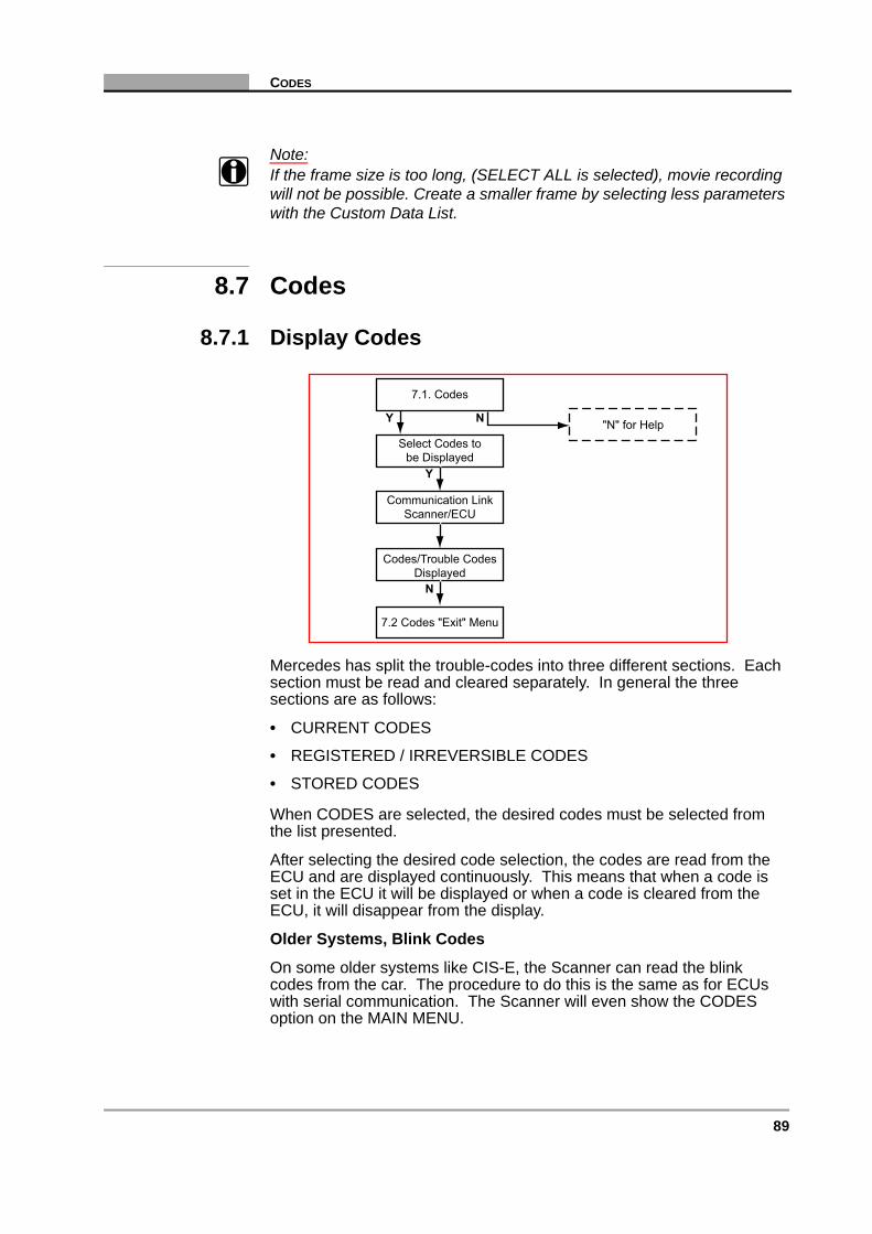
89
CODES
Note:i If the frame size is too long, (SELECT ALL is selected), movie recording
will not be possible. Create a smaller frame by selecting less parameters with the Custom Data List.
8.7 Codes
8.7.1 Display Codes
Mercedes has split the trouble-codes into three different sections. Each section must be read and cleared separately. In general the three sections are as follows:
• CURRENT CODES
• REGISTERED / IRREVERSIBLE CODES
• STORED CODES
When CODES are selected, the desired codes must be selected from the list presented.
After selecting the desired code selection, the codes are read from the ECU and are displayed continuously. This means that when a code is set in the ECU it will be displayed or when a code is cleared from the ECU, it will disappear from the display.
Older Systems, Blink Codes
On some older systems like CIS-E, the Scanner can read the blink codes from the car. The procedure to do this is the same as for ECUs with serial communication. The Scanner will even show the CODES option on the MAIN MENU.
"N" for Help
7.1. Codes
Select Codes tobe Displayed
Communication LinkScanner/ECU
Codes/Trouble CodesDisplayed
7.2 Codes "Exit" Menu
Y
Y
N
N
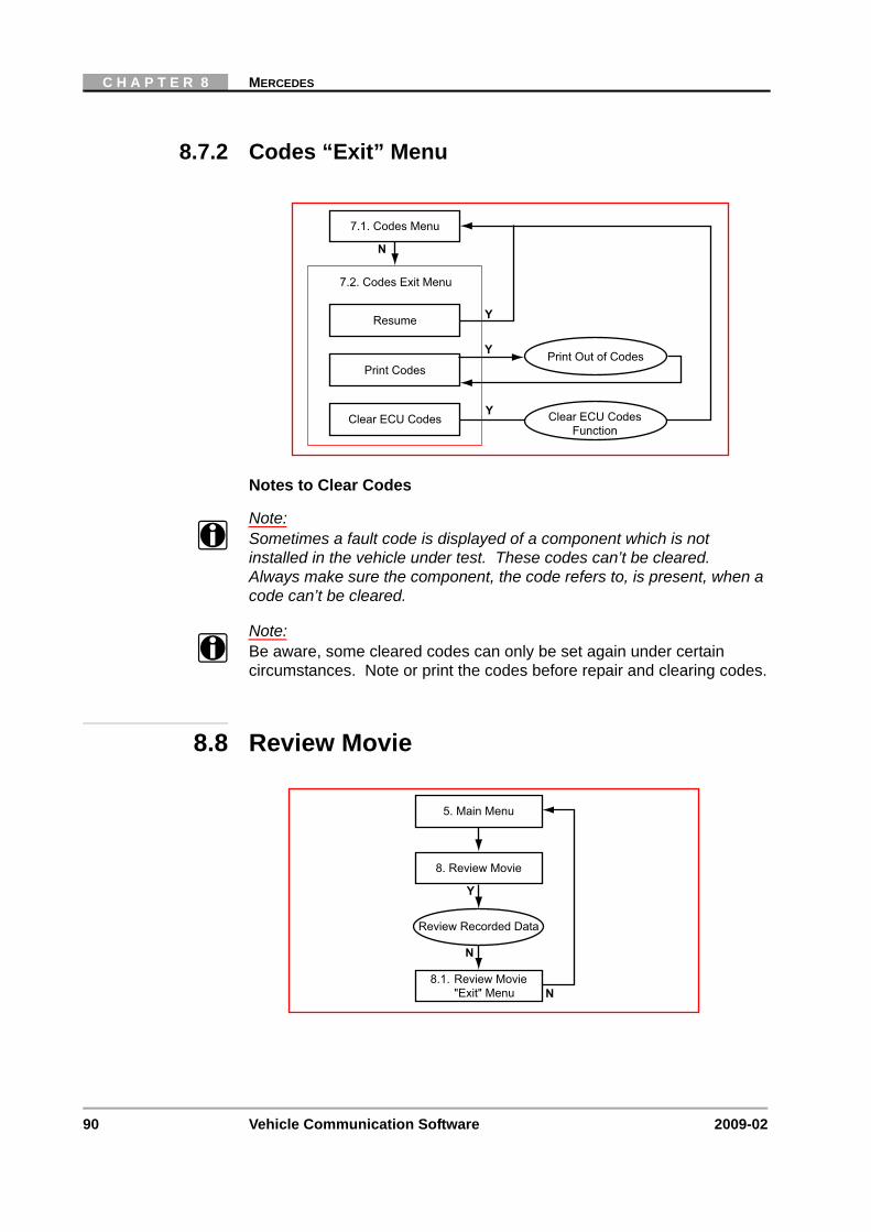
90 Vehicle Communication Software 2009-02
C H A P T E R 8 MERCEDES
8.7.2 Codes “Exit” Menu
Notes to Clear Codes
Note:i Sometimes a fault code is displayed of a component which is not
installed in the vehicle under test. These codes can’t be cleared. Always make sure the component, the code refers to, is present, when a code can’t be cleared.
Note:i Be aware, some cleared codes can only be set again under certain
circumstances. Note or print the codes before repair and clearing codes.
8.8 Review Movie
7.2. Codes Exit Menu
Resume
Y
N
7.1. Codes Menu
Y
Print Codes
Clear ECU Codes
Print Out of Codes
Y Clear ECU CodesFunction
8.1. Review Movie"Exit" Menu
5. Main Menu
8. Review Movie
Y
Review Recorded Data
N
N

91
FUNCTIONAL TESTS
8.8.1 Review Movie “Exit” Menu
8.9 Functional Tests
Actuator Tests
Which actuators can be activated is dependent on the ECU under test and the vehicle itself.
Note:i In some cases a certain actuator may not be present on a vehicle,
although according to the manuals it should be. Therefore, please check this first after failing to hear a reaction from the actuator under test.
Resume
N
Y
Y
N
Print ScreenPrint Frame
8.1. Review Movie Exit Menu
8. Review Movie
Print Out of Screenor Frame
5. Main Menu
Y
N 9.1. Functional Tests Menu
5. Main Menu
"N" for Help9. Functional Tests
YReview ECU IDECU Information N
YReplace ECU
Replace ECUProcedures
YReview CodingDisplay ECU Coding
Information
YActuator TestsPerform Actuator Tests N
92 Vehicle Communication Software 2009-02
C H A P T E R 8 MERCEDES
Note:i Have the engine running only when instructed to do so by the Scanner.
When selecting this feature, the Scanner will give the operator some instructions to get the ECU into the actuator test mode. It is very important that these instructions are followed exactly before the actual actuator test is entered.
Each actuator test has its own help page with additional help for the specific actuator. This is selected when the command line is scrolled to the HELP position and Y is pressed. The Help pages are scrollable, if there is more information concerning a particular item then MORE is displayed, pressing Y returns to the actuator test screen.
Review Coding
This displays the preprogrammed VIN number and some other relevant information fields.
Replace ECU
On various ECUs (ME1.0, ME2.0, ME2.1, EGS, ERE/EVE/ASF) there is the possibility to replace the existing ECU with a new one.
Use this function to read the settings from the “old” ECU (if communication can be established) and write them to the “new” ECU.
Note:i During this procedure, it is important to follow the instructions exactly as
displayed on the Scanner.

93
STOP COMMUNICATION, (OTHER SYSTEMS)
8.10 Stop Communication, (Other Systems)
Use STOP COMMUNICATION, (OTHER SYSTEMS) to select another system and to end the current diagnostic session and to Stop Communication with the ECU.
Caution:ä The ABS System or other ECUs can be damaged or disabled if the
Scanner is disconnected before communication has properly stopped. Always return to the Main Menu and select “Stop Communication, (Other Systems)” before disconnecting the Scanner.
System ListSelect System
Connection Message
Selected System"Main Menu"
2. Identify Vehicle
5. Main Menu
Y N
Y
10. Stop Communication(Other Systems)
"Data Loss"Warning Message
Y N
"N" for Help
"N" for Help
Information Message
Communication LinkScanner/ECU
N Y

94 Vehicle Communication Software 2009-02
C H A P T E R 8 MERCEDES
8.11 Custom Setup
LCD Selection
There are currently two different types of LCD used in the Scanner. Use this function to find out which display is installed in the unit.
On the top line, one of the following lines will be displayed:
LCD [ORIGNAL] : 'üñöx' = 'unox'
Or
LCD [EUROPEAN] : '0123' = '0123'
Press Y if the LCD display is correct and the CUSTOM SETUP menu will be redisplayed.
Press N if the LCD display is incorrect. The Scanner automatically selects the correct LCD display, press Y to return to the CUSTOM SETUP menu.
Y
N 11.1. Custom Setup Menu
5. Main Menu
"N" for Help11. Custom Setup
YCommunication SetupSet Baud Rate Y
YImperial/MetricSet Display Units
YPrinterSelect Printer N
YContrast AdjustSet Backlight Automatic
Shut-off Times Y
YRight/Left HandDrive Setup
Select Right/LeftHand Drive N
YLCD SelectionSelect LCD Type
YAbout
Display SoftwareVersion Information N

95
9 MG/Rover
Overview
This flow diagram represents the basic operation of the software. The numbers beside each item refer to the various headings in this chapter.
1. Start-up Sequence“N” for Help
2. Identify Vehicle
4. Connect Scanner
5. Main Menu TroubleShooter“N” for Help
Y N
3. Select System
10. CustomSetup
10.1. CustomSetup Menu
7. ReviewMovie
9. Stop(Other
Systems)
9.1.Systems
List
7.1. MovieExit Menu
Codes only
6. Codes &Data Menu Data Only
Data OnlyExit Menu
6.1. Codes& Data
Exit Menu
Codes OnlyExit Menu
8.Functional
Tests
8.1.FunctionalTests Menu
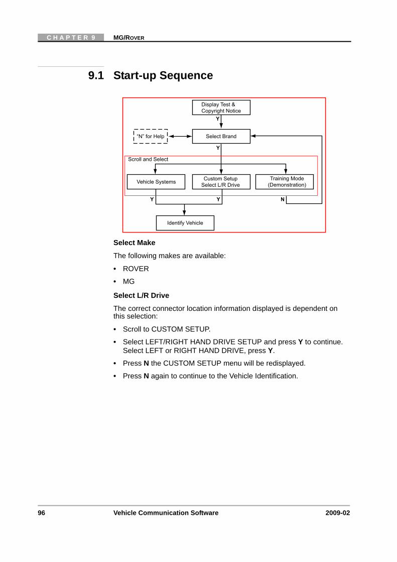
96 Vehicle Communication Software 2009-02
C H A P T E R 9 MG/ROVER
9.1 Start-up Sequence
Select Make
The following makes are available:
• ROVER
• MG
Select L/R Drive
The correct connector location information displayed is dependent on this selection:
• Scroll to CUSTOM SETUP.
• Select LEFT/RIGHT HAND DRIVE SETUP and press Y to continue. Select LEFT or RIGHT HAND DRIVE, press Y.
• Press N the CUSTOM SETUP menu will be redisplayed.
• Press N again to continue to the Vehicle Identification.
Display Test &Copyright Notice
“N” for Help Select Brand
Vehicle Systems Training Mode(Demonstration)
Identify Vehicle
Scroll and Select
Y Y
Y
Y
N
Custom SetupSelect L/R Drive
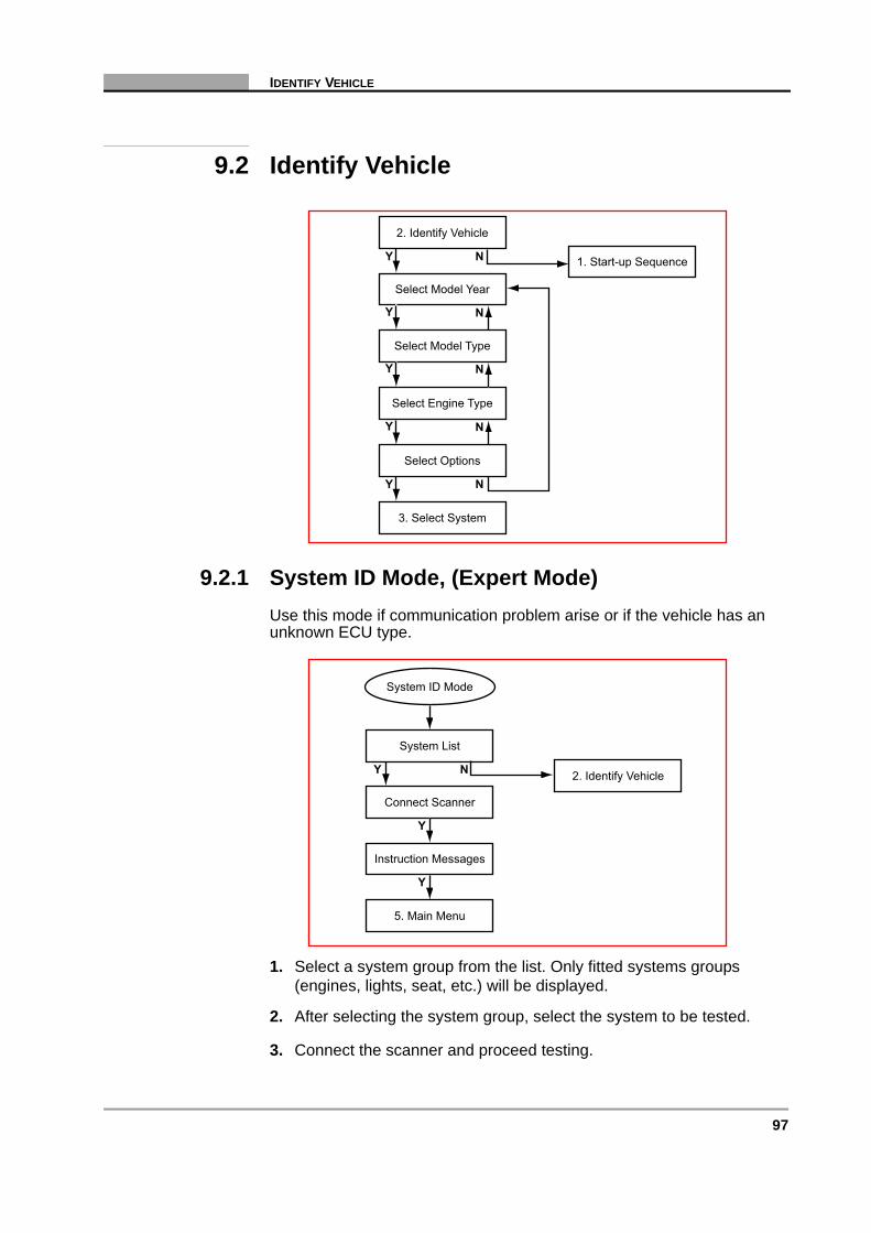
97
IDENTIFY VEHICLE
9.2 Identify Vehicle
9.2.1 System ID Mode, (Expert Mode)Use this mode if communication problem arise or if the vehicle has an unknown ECU type.
1. Select a system group from the list. Only fitted systems groups (engines, lights, seat, etc.) will be displayed.
2. After selecting the system group, select the system to be tested.
3. Connect the scanner and proceed testing.
1. Start-up Sequence
2. Identify Vehicle
Select Model Year
Select Model Type
Select Engine Type
Select Options
3. Select System
Y N
Y
Y
Y N
Y N
N
N
System List
Connect Scanner
Instruction Messages
System ID Mode
2. Identify Vehicle
5. Main Menu
Y N
Y
Y

98 Vehicle Communication Software 2009-02
C H A P T E R 9 MG/ROVER
9.3 Select System to be Tested
9.3.1 System ListThe systems list will remain active until a new vehicle is selected. Scroll to the selected the system to be tested and press Y to confirm.
Note:i Refer to the Documentation CD for a complete list of systems available.
9.3.2 Additional Notes:No Communication:
If there is NO COMMUNICATION it is advisable to select the ECU type, if known, from the TEST entry to determine if the ECU is communicating.
This can be found in the Vehicle ID selection by choosing 1987 /TEST / the ECU name. All available ECU types are located here.
9.4 Connect Scanner
System List
2. Identify Vehicle
5. Main Menu
4. Connect Scanner
3. Select System
Y N
Y
System List
2. Identify Vehicle
5. Main Menu
Communication:Scanner/ECU
Y N
Connection Messages
Y

99
MAIN MENU
Note:i See the “Adaptors Overview & Data Parameters” manual for details.
9.5 Main Menu
9.6 Codes & Data
6.1. Codes & Data"Exit" Menu6. Codes & Data
N
N
N
N
N
N
Y
N
Y
N
Y
7. Review Movie
8. Functional Tests
9. Stop Communication(Other Systems)
10. Custom Setup
"N" for Help5. Main Menu
7.1. Review Movie"Exit" Menu
8.1. FunctionalTests Menu
9.1. Systems List
10.1. Custom SetupMenu
Codes Only "Exit"MenuCodes Only
N
N
Data Only "Exit" MenuData OnlyN
N
"N" for Help2. Codes & Data
Communication LinkScanner/ECU
Holding Data Frames
Y
Y
N
NY N
Codes/Data Lists:Codes, Data Parameters
6.1. Codes & Data"Exit" Menu
Y

100 Vehicle Communication Software 2009-02
C H A P T E R 9 MG/ROVER
9.6.1 Data (No Codes)Displays live data parameters, scroll for complete list.
Press N for the Data (No Codes) “Exit Menu.
9.6.2 Codes OnlyDisplays the Diagnostic Trouble Codes (DTCs), scroll for complete list.
Press N for the Codes Only “Exit Menu.
9.6.3 Codes & Data “Exit” Menu
Resume
N
Y
Y
N
Y
N
Y
Y
Print ScreenPrint Frame
Arm Movie
LED Menu
Clear ECU Codes
6.1. Codes & Data Exit Menu
6. Codes & Data
Custom Data List Select Data Parametersto be Displayed
Clear ECU CodesFunction
Assign LED Functions
"Arm" and RecordMovie for Review
Print Out of Screenor Frame
Y
Y
YFix/Release Lines Fix/Release DataDisplay Lines

101
REVIEW MOVIE
9.7 Review Movie
9.7.1 Review Movie “Exit” Menu
7.1. Review Movie"Exit" Menu
5. Main Menu
7. Review Movie
Y
Review Recorded Data
N
N
Resume
N
Y
Y
N
N
Y
Print ScreenPrint Frame
LED Menu
7.1. Review Movie Exit Menu
7. Review Movie
Assign LED Functions
Print Out of Screenor Frame
5. Main Menu
NYFix/Release Lines
Fix/Release DataDisplayLines

102 Vehicle Communication Software 2009-02
C H A P T E R 9 MG/ROVER
9.8 Functional Tests
Actuator Tests: The number of actuators that can be activated is dependent on the ECU under test and the vehicle itself. For example:
• RPM Signal
• Purge Control Solenoid
• Main Relay
• Fuel Pump Relay
• Malfunction Indicator Light
• Engine Fan Relay
• Cruise Lamp
• O2 Sensor Heater Relay
• Injectors
Special Functions, (Sub-menu), Example:
• Ignition Coil 1 Charge Time
• Ignition Coil 2 Charge Time
Y
N 8.1. Functional Tests Menu
5. Main Menu
"N" for Help8. Functional Tests
YReview ECU IDECU Information Y
YSpecial Functions
Special FunctionsTest Menu
YFuel Adjust
Perform FuelAdjustments Y
YIgnition Adjust
Perform IgnitionAdjustments Y
YActuator TestsPerform Actuator Tests N
N

103
STOP COMMUNICATION, (OTHER SYSTEMS)
9.9 Stop Communication, (Other Systems)
Use STOP COMMUNICATION (OTHER SYSTEMS) to end the current diagnostic session and to Stop Communication with the ECU.
Caution:ä The ABS System or ECU can be damaged or disabled if the
Scanner is disconnected before communication has properly stopped. Always return to the Main Menu and select “Stop Communication (Other Systems)” before disconnecting the Scanner.
System ListSelect System
Connection Message
Select System"Main Menu"
2. Identify Vehicle
5. Main Menu
Y N
Y
9. Stop Communication(Other Systems)
"Data Loss"Warning Message
Y N
"N" for Help
"N" for Help

104 Vehicle Communication Software 2009-02
C H A P T E R 9 MG/ROVER
9.10 Custom Setup
Y
N 10.1. Custom Setup Menu
5. Main Menu
"N" for Help10. Custom Setup
YCommunication SetupSet Baud Rate Y
YImperial/MetricSet Display Units
YAbout
Display SoftwareVersion Information N
YContrast AdjustSet Backlight Automatic
Shut-off Times Y
YLED MenuAssign LED Functions N
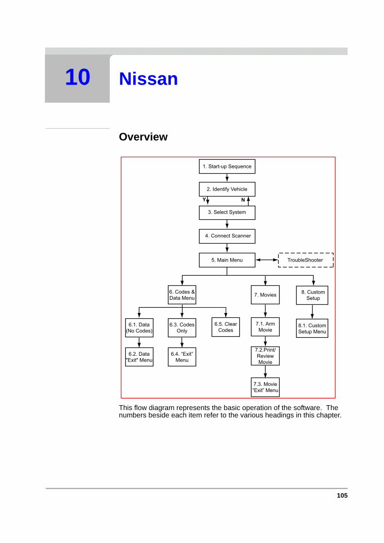
105
10 Nissan
Overview
This flow diagram represents the basic operation of the software. The numbers beside each item refer to the various headings in this chapter.
1. Start-up Sequence
2. Identify Vehicle
4. Connect Scanner
5. Main Menu TroubleShooter
Y N
3. Select System
6.5. ClearCodes
6.4. “Exit”Menu
8. CustomSetup
8.1. CustomSetup Menu
7. Movies
7.1. ArmMovie
7.2.Print/ReviewMovie
7.3. Movie“Exit” Menu
6.3. CodesOnly
6. Codes &Data Menu
6.1. Data(No Codes)
6.2. Data"Exit" Menu

106 Vehicle Communication Software 2009-02
C H A P T E R 10 NISSAN
10.1 Start-up Sequence
Select
• “Honda/Nissan/Toyota”.
Select Make
• Nissan
10.2 Identify Vehicle
Y
N
Display Test and Copyright Notice
Select"Honda/Nissan/Toyota"
2. Identify Vehicle
Select MakeN
1. Start-up Sequence
2. Identify Vehicle
Select Model Year
Select Model Type
Select Engine Type
Select Options
3. Select System
Y N
Y
Y
Y N
Y N
N
N
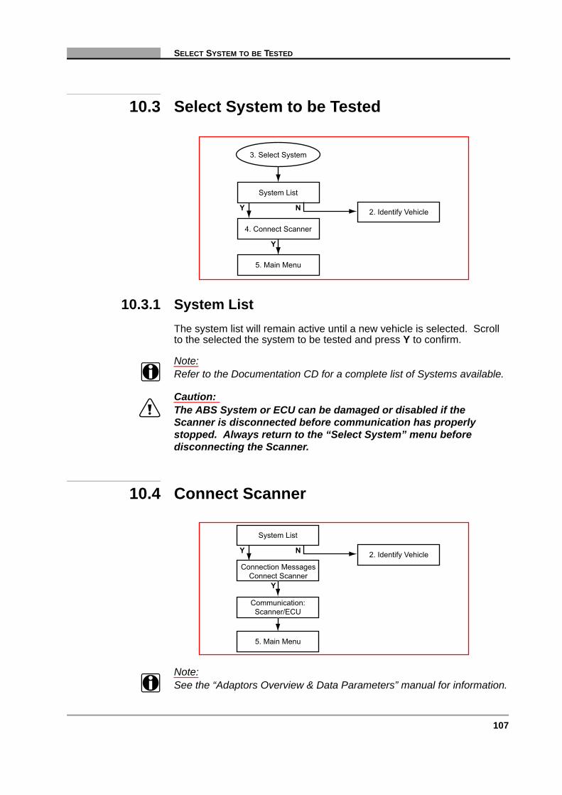
107
SELECT SYSTEM TO BE TESTED
10.3 Select System to be Tested
10.3.1 System ListThe system list will remain active until a new vehicle is selected. Scroll to the selected the system to be tested and press Y to confirm.
Note:i Refer to the Documentation CD for a complete list of Systems available.
Caution:ä The ABS System or ECU can be damaged or disabled if the
Scanner is disconnected before communication has properly stopped. Always return to the “Select System” menu before disconnecting the Scanner.
10.4 Connect Scanner
Note:i See the “Adaptors Overview & Data Parameters” manual for information.
System List
2. Identify Vehicle
5. Main Menu
4. Connect Scanner
3. Select System
Y N
Y
System List
2. Identify Vehicle
5. Main Menu
Communication:Scanner/ECU
Y N
Connection MessagesConnect Scanner
Y

108 Vehicle Communication Software 2009-02
C H A P T E R 10 NISSAN
10.5 Main Menu
10.6 Codes & Data Menu
7.1. Arm Movie7. Movies NY
N
Y
N
Y
7.3. Exit Menu
8. Custom Setup
7.2. Print &Review Movie
8.1. Custom SetupMenu
5. Main Menu
6.1. Data (No Codes)6. Codes & Data Menu Y
N
N
N
N
6.3. Codes Only
6.4. Exit Menu
6.2. Exit Menu
Y
6.5. Clear CodesYN
N
Y
9. Actuator Tests 9.1. Perform ActuatorTests
N
6.1. Data (No Codes)
6. Codes & Data Menu
Y
N
N
N
6.3. Codes Only
6.4. Exit Menu
6.2. Exit Menu
Y
6.5. Clear CodesYN
N
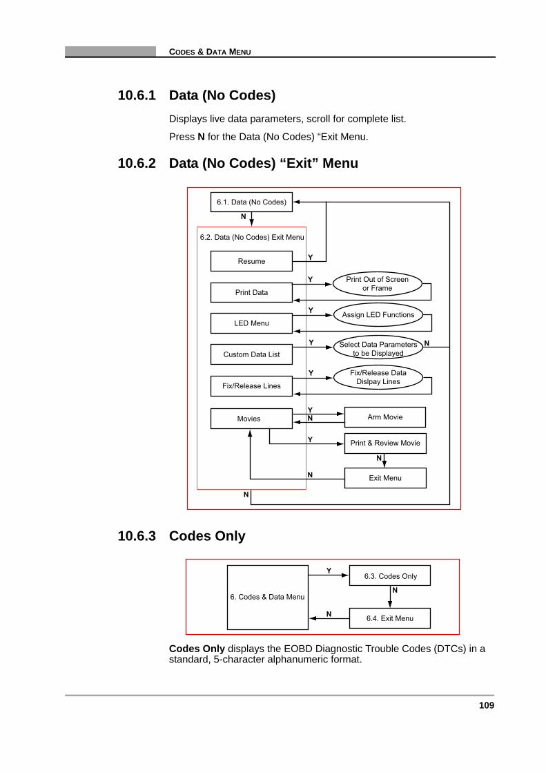
109
CODES & DATA MENU
10.6.1 Data (No Codes)Displays live data parameters, scroll for complete list.
Press N for the Data (No Codes) “Exit Menu.
10.6.2 Data (No Codes) “Exit” Menu
10.6.3 Codes Only
Codes Only displays the EOBD Diagnostic Trouble Codes (DTCs) in a standard, 5-character alphanumeric format.
6.2. Data (No Codes) Exit Menu
Resume
Y
N
N
6.1. Data (No Codes)
Y
N
Arm MovieMovies NY
N
Y
Exit Menu
Print & Review Movie
N
Print Data
LED Menu
Custom Data List
Fix/Release Lines
Select Data Parametersto be Displayed
Fix/Release DataDislpay Lines
Assign LED Functions
Print Out of Screenor Frame
Y
Y
Y
N
Y6.3. Codes Only
6.4. Exit Menu
6. Codes & Data MenuN

110 Vehicle Communication Software 2009-02
C H A P T E R 10 NISSAN
10.6.4 Codes Only “Exit” Menu
10.6.5 Clear CodesNotes to Clear Codes
Note:i Be aware, some cleared codes can only be set again under certain
circumstances. Note or print the codes before repair and clearing codes.
Note:i When the error condition still exists, the ECU can set the code again.
If the code clearing operation fails for any reason, the previous codes reappear. If this occurs, press N to return to the Codes & Data menu and repeat the Clear Codes operation.
10.7 Movies
6.4. Codes Only Exit Menu
Resume
Y
N
6.3. Codes Only
Y
Print Codes
Return to Main Menu
Print Out of Codes
Y
N
5. Main Menu
7.1. Arm Movie
7. Movies
NY
7.3. Exit Menu
7.2. Print &Review Movie
N
N
Y
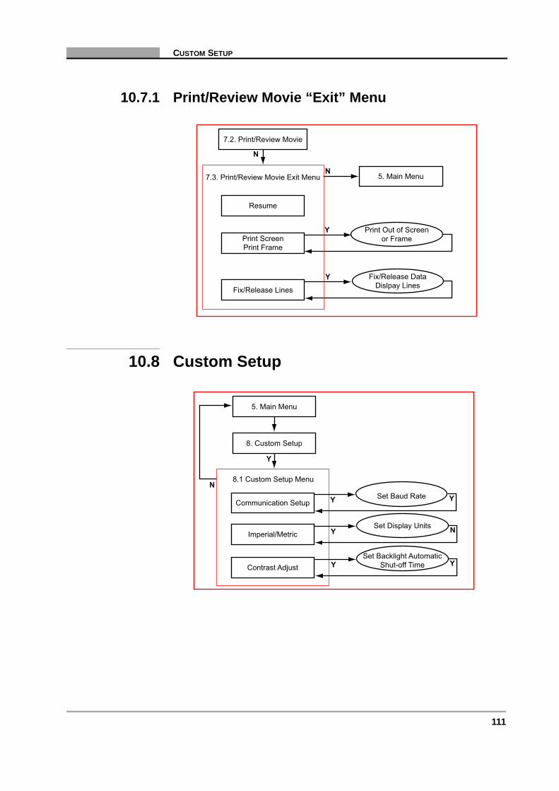
111
CUSTOM SETUP
10.7.1 Print/Review Movie “Exit” Menu
10.8 Custom Setup
7.3. Print/Review Movie Exit Menu
Resume
Y
N
7.2. Print/Review Movie
Print ScreenPrint Frame
Fix/Release Lines
Fix/Release DataDislpay Lines
Print Out of Screenor Frame
Y
5. Main MenuN
8.1 Custom Setup Menu
Y
N
5. Main Menu
Communication Setup
Imperial/Metric
Contrast AdjustSet Backlight Automatic
Shut-off Time
Set Display Units
Set Baud Rate
Y
Y
8. Custom Setup
Y
Y
Y
N
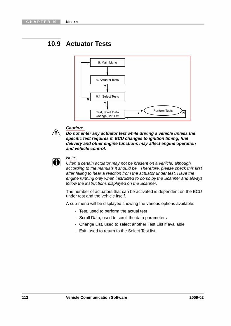
112 Vehicle Communication Software 2009-02
C H A P T E R 10 NISSAN
10.9 Actuator Tests
Caution:ä Do not enter any actuator test while driving a vehicle unless the
specific test requires it. ECU changes to ignition timing, fuel delivery and other engine functions may affect engine operation and vehicle control.
Note:i Often a certain actuator may not be present on a vehicle, although
according to the manuals it should be. Therefore, please check this first after failing to hear a reaction from the actuator under test. Have the engine running only when instructed to do so by the Scanner and always follow the instructions displayed on the Scanner.
The number of actuators that can be activated is dependent on the ECU under test and the vehicle itself.
A sub-menu will be displayed showing the various options available:
- Test, used to perform the actual test- Scroll Data, used to scroll the data parameters- Change List, used to select another Test List if available- Exit, used to return to the Select Test list
9. Actuator tests
N
9.1. Select Tests
Test, Scroll DataChange List, Exit
Perform TestsY
5. Main Menu
Y
Y
N

113
11 Opel/Vauxhall
Overview
This flow diagram represents the basic operation of the software. The numbers beside each item refer to the various headings in this chapter.
1. Start-up Sequence“N” for Help
2. Identify Vehicle
4. Connect Scanner
5. Main Menu TroubleShooter“N” for Help
Y N
3. Select System
10. CustomSetup
10.1. CustomSetup Menu
7. ReviewMovie
9. Stop(Other
Systems)
9.1.Systems
List
7.1. MovieExit Menu
Codes only
6. Codes &Data Menu Data Only
Data OnlyExit Menu
6.1. Codes& Data
Exit Menu
Codes OnlyExit Menu
8.Functional
Tests
8.1.FunctionalTests Menu
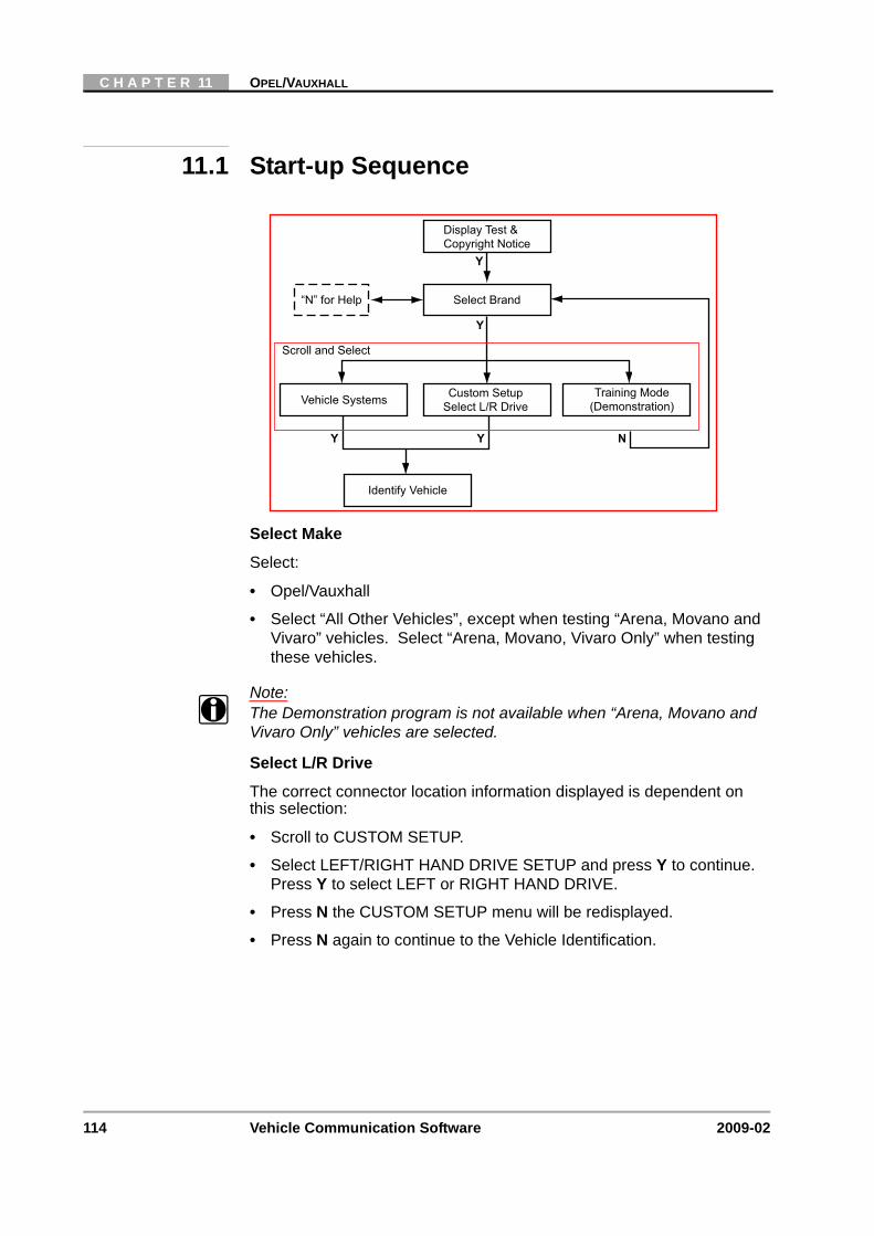
114 Vehicle Communication Software 2009-02
C H A P T E R 11 OPEL/VAUXHALL
11.1 Start-up Sequence
Select Make
Select:
• Opel/Vauxhall
• Select “All Other Vehicles”, except when testing “Arena, Movano and Vivaro” vehicles. Select “Arena, Movano, Vivaro Only” when testing these vehicles.
Note:i The Demonstration program is not available when “Arena, Movano and
Vivaro Only” vehicles are selected.
Select L/R Drive
The correct connector location information displayed is dependent on this selection:
• Scroll to CUSTOM SETUP.
• Select LEFT/RIGHT HAND DRIVE SETUP and press Y to continue. Press Y to select LEFT or RIGHT HAND DRIVE.
• Press N the CUSTOM SETUP menu will be redisplayed.
• Press N again to continue to the Vehicle Identification.
Display Test &Copyright Notice
“N” for Help Select Brand
Vehicle Systems Training Mode(Demonstration)
Identify Vehicle
Scroll and Select
Y Y
Y
Y
N
Custom SetupSelect L/R Drive
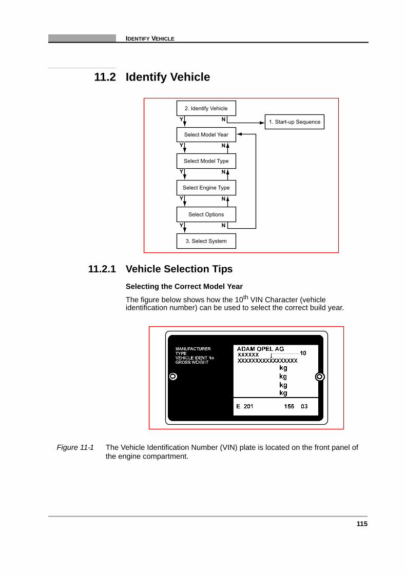
115
IDENTIFY VEHICLE
11.2 Identify Vehicle
11.2.1 Vehicle Selection TipsSelecting the Correct Model Year
The figure below shows how the 10th VIN Character (vehicle identification number) can be used to select the correct build year.
Figure 11-1 The Vehicle Identification Number (VIN) plate is located on the front panel of the engine compartment.
1. Start-up Sequence
2. Identify Vehicle
Select Model Year
Select Model Type
Select Engine Type
Select Options
3. Select System
Y N
Y
Y
Y N
Y N
N
N
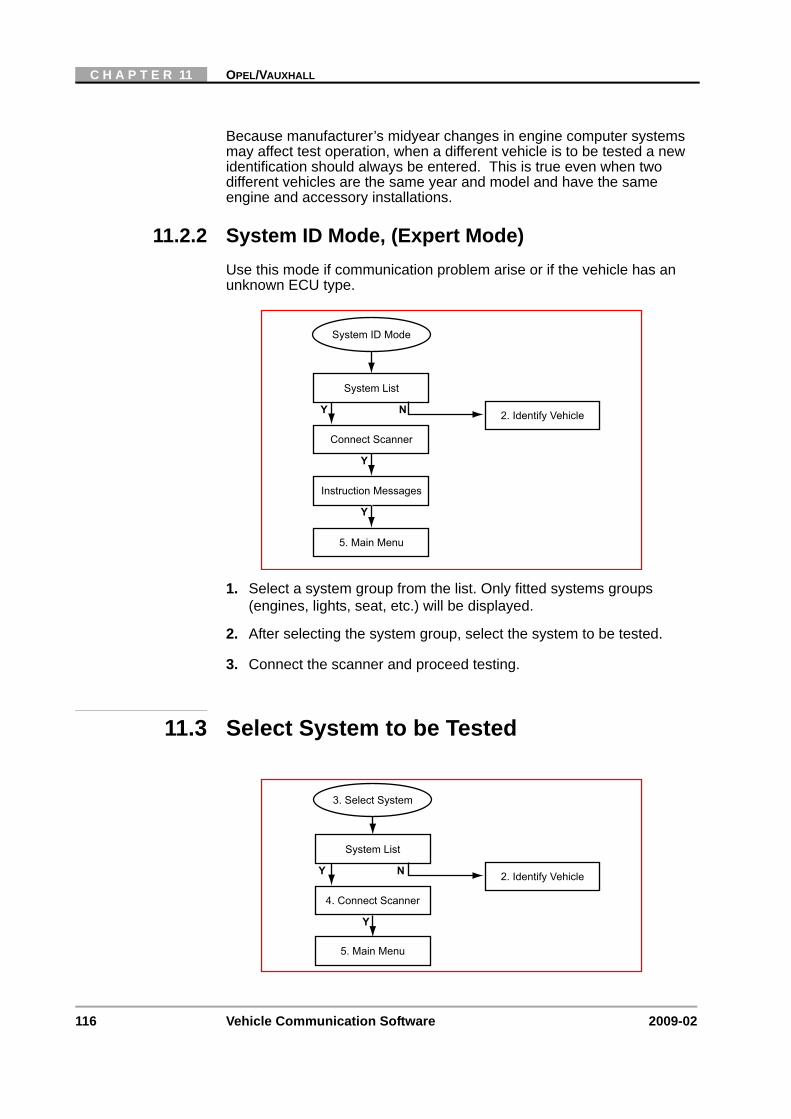
116 Vehicle Communication Software 2009-02
C H A P T E R 11 OPEL/VAUXHALL
Because manufacturer’s midyear changes in engine computer systems may affect test operation, when a different vehicle is to be tested a new identification should always be entered. This is true even when two different vehicles are the same year and model and have the same engine and accessory installations.
11.2.2 System ID Mode, (Expert Mode)Use this mode if communication problem arise or if the vehicle has an unknown ECU type.
1. Select a system group from the list. Only fitted systems groups (engines, lights, seat, etc.) will be displayed.
2. After selecting the system group, select the system to be tested.
3. Connect the scanner and proceed testing.
11.3 Select System to be Tested
System List
Connect Scanner
Instruction Messages
System ID Mode
2. Identify Vehicle
5. Main Menu
Y N
Y
Y
System List
2. Identify Vehicle
5. Main Menu
4. Connect Scanner
3. Select System
Y N
Y

117
CONNECT SCANNER
11.3.1 System ListThe System List displayed is dependent on the selected vehicle. Listed below are some of the possible systems available:
• ENGINE
• AIRBAG
• ANTI-LOCK BRAKES
Note:i Refer to the Documentation CD for a complete list of Systems available.
11.3.2 Additional Notes:No Communication
If there is NO COMMUNICATION it is advisable to select the ECU type, if known, from the TEST entry to determine if the ECU is communicating.
This can be found in the Vehicle ID selection by choosing 1987 /TEST / the ECU name. All available ECU types are located here.
Note:i When testing certain vehicles, communication problems may occur when
the engine revs are above 2000 rpm. Once communication has been re-established, the engine may be revved above 2000 rpm.
Note:i When testing Automatic Transmission Systems the engine MUST be
OFF and the Transmission must be in Park or Neutral in order to establish communication. Once communication has been established, the engine may be started and the transmission can be set to Drive.
11.4 Connect Scanner
System List
5. Main Menu
Communication:Scanner/ECU
Y
Connection Messages
Y
2. Identify VehicleN
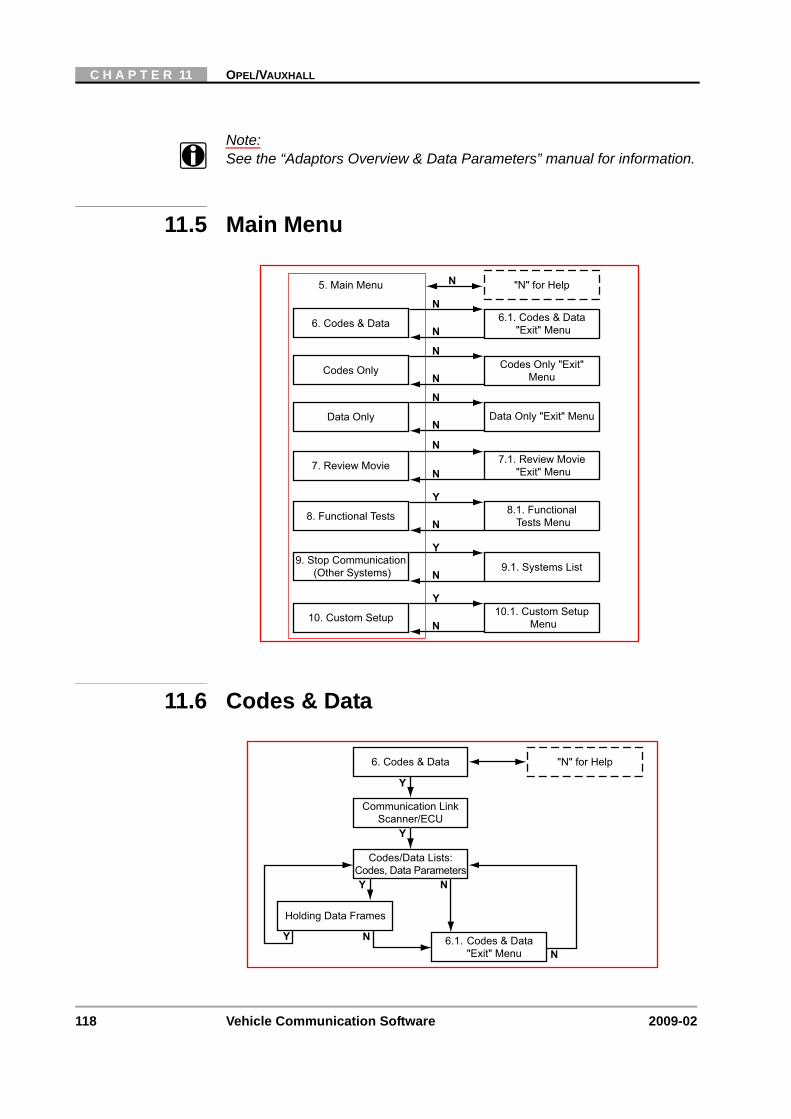
118 Vehicle Communication Software 2009-02
C H A P T E R 11 OPEL/VAUXHALL
Note:i See the “Adaptors Overview & Data Parameters” manual for information.
11.5 Main Menu
11.6 Codes & Data
6.1. Codes & Data"Exit" Menu6. Codes & Data
N
N
N
N
N
N
Y
N
Y
N
Y
7. Review Movie
8. Functional Tests
9. Stop Communication(Other Systems)
10. Custom Setup
"N" for Help5. Main Menu
7.1. Review Movie"Exit" Menu
8.1. FunctionalTests Menu
9.1. Systems List
10.1. Custom SetupMenu
Codes Only "Exit"MenuCodes Only
N
N
Data Only "Exit" MenuData OnlyN
N
"N" for Help6. Codes & Data
Communication LinkScanner/ECU
Holding Data Frames
Y
Y
N
NY N
Codes/Data Lists:Codes, Data Parameters
6.1. Codes & Data"Exit" Menu
Y
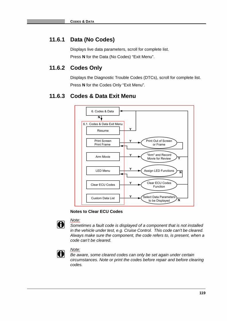
119
CODES & DATA
11.6.1 Data (No Codes)Displays live data parameters, scroll for complete list.
Press N for the Data (No Codes) “Exit Menu”.
11.6.2 Codes OnlyDisplays the Diagnostic Trouble Codes (DTCs), scroll for complete list.
Press N for the Codes Only “Exit Menu”.
11.6.3 Codes & Data Exit Menu
Notes to Clear ECU Codes
Note:i Sometimes a fault code is displayed of a component that is not installed
in the vehicle under test, e.g. Cruise Control. This code can’t be cleared. Always make sure the component, the code refers to, is present, when a code can’t be cleared.
Note:i Be aware, some cleared codes can only be set again under certain
circumstances. Note or print the codes before repair and before clearing codes.
Resume
N
Y
Y
N
Y
N
Y
Y
Print ScreenPrint Frame
Arm Movie
LED Menu
Clear ECU Codes
6.1. Codes & Data Exit Menu
6. Codes & Data
Custom Data List Select Data Parametersto be Displayed
Clear ECU CodesFunction
Assign LED Functions
"Arm" and RecordMovie for Review
Print Out of Screenor Frame
Y
Y

120 Vehicle Communication Software 2009-02
C H A P T E R 11 OPEL/VAUXHALL
Note:i When the error condition still exists, the ECU can set the code again.
11.7 Review Movie
11.7.1 Review Movie “Exit” Menu
7.1. Review Movie"Exit" Menu
5. Main Menu
7. Review Movie
Y
Review Recorded Data
N
N
Resume
N
Y
Y
N
N
Y
Print ScreenPrint Frame
LED Menu
7.1. Review Movie Exit Menu
7. Review Movie
Assign LED Functions
Print Out of Screenor Frame
5. Main Menu

121
FUNCTIONAL TESTS
11.8 Functional Tests
Actuator Tests: The number of actuators that can be activated is dependent on the ECU under test and the vehicle itself. For example:
• Fuel Pump Relay
• Idle Air Control Valve
• Fuel Tank Vent Valve
Engine Actuator Test Notes
Note:i Often a certain actuator may not be present on a vehicle, although
according to the manuals it should be. Therefore, please check this first after failing to hear a reaction from the actuator under test. Have the engine running only when instructed to do so by the Scanner and always follow the instructions displayed on the Scanner.
Note:i With some engines hearing the injectors click is very difficult. Use a
multimeter or scope to make sure or check that the injectors are activated properly.
Note:i Some actuators will be activated for a short time. For example, the
injectors will be activated for only five seconds, this is for safety reasons.
Y
N 8.1. Functional Tests Menu
5. Main Menu
"N" for Help8. Functional Tests
YReview ECU IDDisplay ECU Information N
YPrint ECU ID
Print Out ECUInformation
YActuator TestsPerform Actuator Tests N
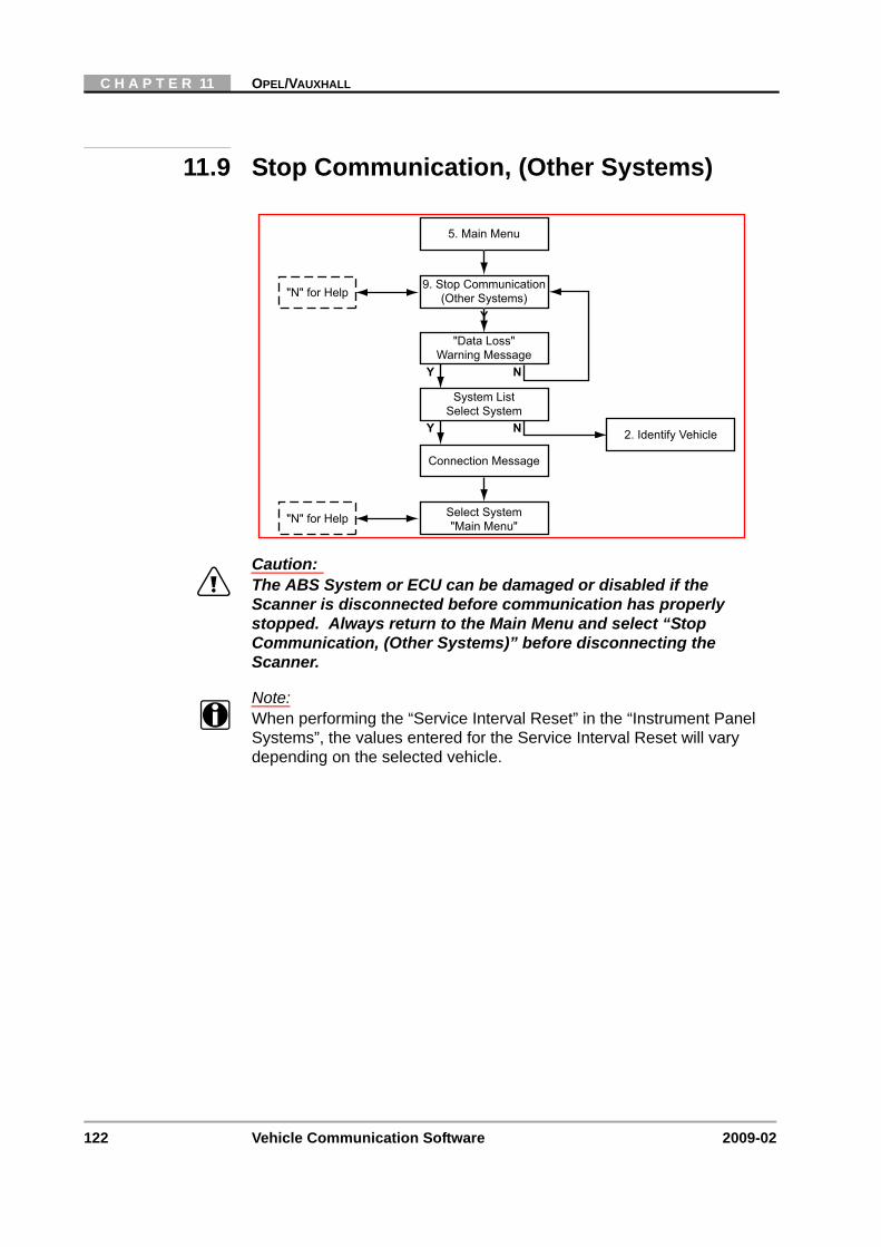
122 Vehicle Communication Software 2009-02
C H A P T E R 11 OPEL/VAUXHALL
11.9 Stop Communication, (Other Systems)
Caution:ä The ABS System or ECU can be damaged or disabled if the
Scanner is disconnected before communication has properly stopped. Always return to the Main Menu and select “Stop Communication, (Other Systems)” before disconnecting the Scanner.
Note:i When performing the “Service Interval Reset” in the “Instrument Panel
Systems”, the values entered for the Service Interval Reset will vary depending on the selected vehicle.
System ListSelect System
Connection Message
Select System"Main Menu"
2. Identify Vehicle
5. Main Menu
Y N
Y
9. Stop Communication(Other Systems)
"Data Loss"Warning Message
Y N
"N" for Help
"N" for Help

123
CUSTOM SETUP
11.10 Custom Setup
Y
N 10.1. Custom Setup Menu
5. Main Menu
"N" for Help10. Custom Setup
YCommunication SetupSet Baud Rate Y
YImperial/MetricSet Display Units
YAbout
Display SoftwareVersion Information N
YContrast AdjustSet Backlight Automatic
Shut-off Times Y
YLED MenuAssign LED Functions N

124 Vehicle Communication Software 2009-02
C H A P T E R 11 OPEL/VAUXHALL
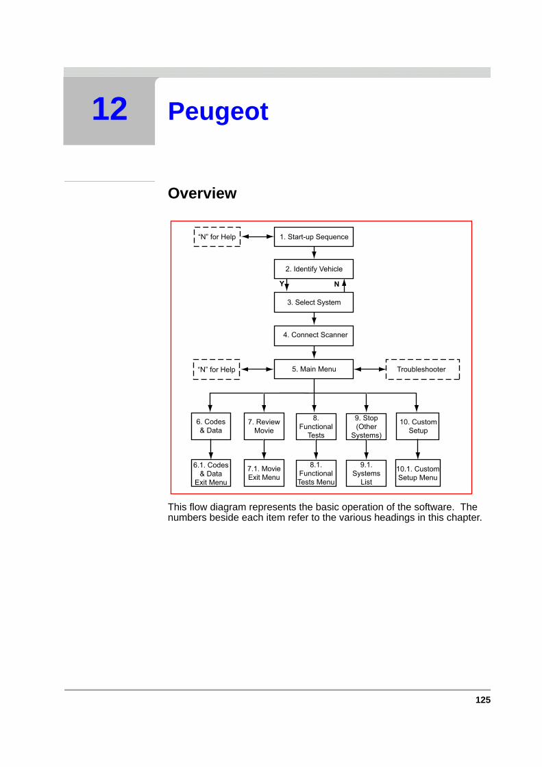
125
12 Peugeot
Overview
This flow diagram represents the basic operation of the software. The numbers beside each item refer to the various headings in this chapter.
1. Start-up Sequence“N” for Help
2. Identify Vehicle
4. Connect Scanner
5. Main Menu“N” for Help
Y N
3. Select System
10. CustomSetup
10.1. CustomSetup Menu
7. ReviewMovie
9. Stop(Other
Systems)
9.1.Systems
List
7.1. MovieExit Menu
6. Codes& Data
6.1. Codes& Data
Exit Menu
8.Functional
Tests
8.1.FunctionalTests Menu
Troubleshooter

126 Vehicle Communication Software 2009-02
C H A P T E R 12 PEUGEOT
12.1 Start-up Sequence
Select Make
Select:
• Peugeot
Select L/R Drive
The correct connector location information displayed is dependent on this selection:
• Scroll to CUSTOM SETUP.
• Select LEFT/RIGHT HAND DRIVE SETUP and press Y to continue. Select LEFT or RIGHT HAND DRIVE, press Y.
• Press N the CUSTOM SETUP menu will be redisplayed.
• Press N again to continue to the Vehicle Identification.
Display Test &Copyright Notice
“N” for Help Select Make
Vehicle Systems Demonstration
2. Identify Vehicle
Scroll and Select
Y Y
Y
Y
N
Custom SetupSelect L/R Drive
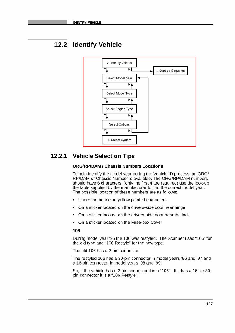
127
IDENTIFY VEHICLE
12.2 Identify Vehicle
12.2.1 Vehicle Selection TipsORG/RP/DAM / Chassis Numbers Locations
To help identify the model year during the Vehicle ID process, an ORG/RP/DAM or Chassis Number is available. The ORG/RP/DAM numbers should have 6 characters, (only the first 4 are required) use the look-up the table supplied by the manufacturer to find the correct model year. The possible location of these numbers are as follows:
• Under the bonnet in yellow painted characters
• On a sticker located on the drivers-side door near hinge
• On a sticker located on the drivers-side door near the lock
• On a sticker located on the Fuse-box Cover
106
During model year ‘96 the 106 was restyled. The Scanner uses “106” for the old type and “106 Restyle” for the new type.
The old 106 has a 2-pin connector.
The restyled 106 has a 30-pin connector in model years ‘96 and ‘97 and a 16-pin connector in model years ‘98 and ‘99.
So, if the vehicle has a 2-pin connector it is a “106”. If it has a 16- or 30-pin connector it is a “106 Restyle”.
1. Start-up Sequence
2. Identify Vehicle
Select Model Year
Select Model Type
Select Engine Type
Select Options
3. Select System
Y N
Y
Y
Y N
Y N
N
N

128 Vehicle Communication Software 2009-02
C H A P T E R 12 PEUGEOT
306
During model year ‘97 the 306 was restyled. The Scanner uses “306” for the old type and “306 Restyle” for the new type.
The old 306 has a 2-pin connector.
The restyled 306 has a 16-pin connector. So, if the vehicle has a 2-pin connector it is a “306”. If it has a 16-pin connector it is a “306 Restyle”.
406, 806 and EXPERT
(DHX 1.9L Turbo-Diesel Engine).
This engine can have a Lucas pump or a Bosch VP20 pump.
If it has a Bosch VP20 pump select engine type: “1.9L T-DSL BOSCH VP20 = DHX”.
For any other pump select engine type: “1.9L T-DSL OTHER = DHX”.
605
The 605 up to model year ‘94 has a 2-pin connector located on the front of the ECU in the engine compartment.
605’s from model year ‘95 and later have a 30-pin connector located on the passenger side behind a panel on the lower dashboard.
So, when a vehicle has a 2-pin connector it is a ‘94 or older and if it has a 30-pin connector it is a ‘95 or later.
Air Bags
The Scanner can only communicate with an Air Bag if it has a connection to the diagnostic connector. Some Air Bags do not have this connection. These Air Bags can be identified by the presence of a LED on the right side of the steering wheel.
12.2.2 System ID ModeUse this mode if communication problem arise or if the vehicle has an unknown ECU type.
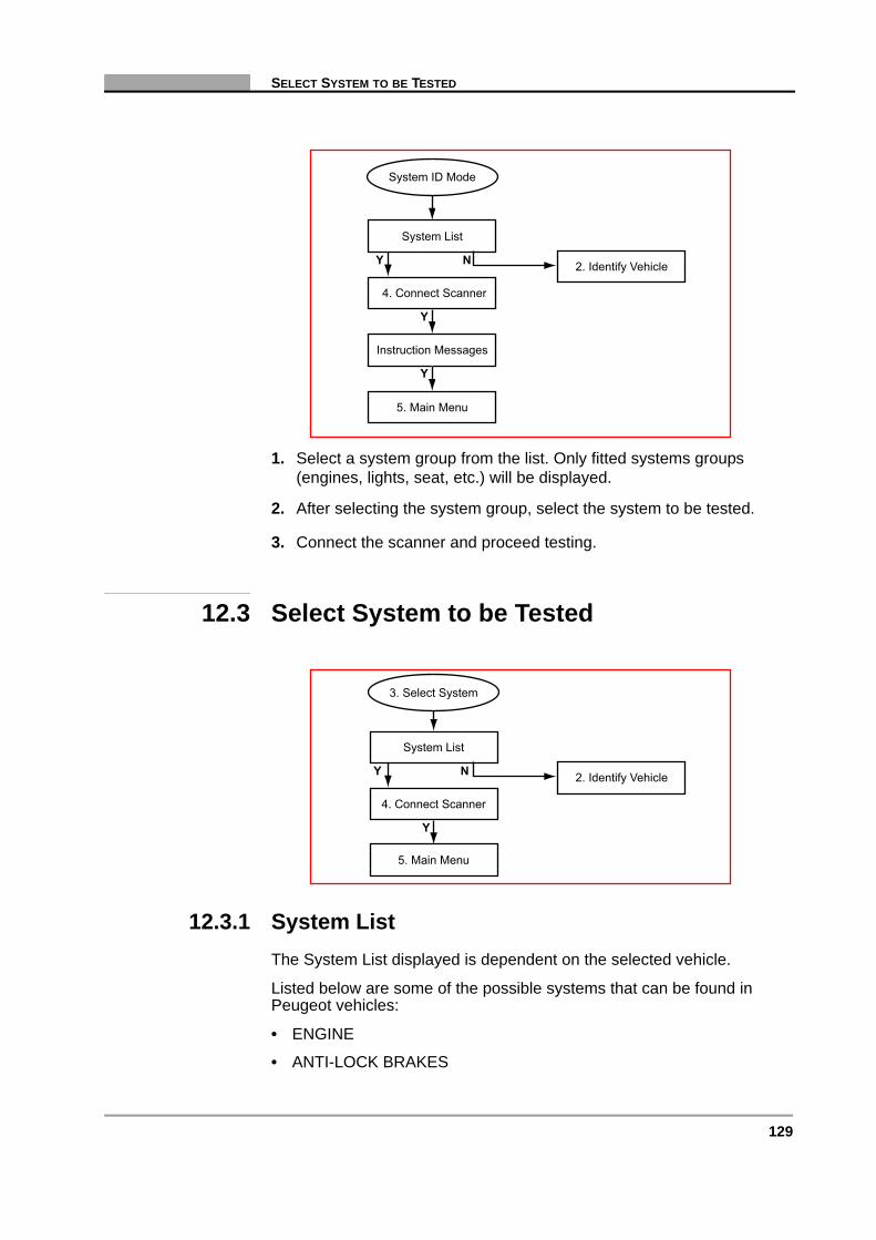
129
SELECT SYSTEM TO BE TESTED
1. Select a system group from the list. Only fitted systems groups (engines, lights, seat, etc.) will be displayed.
2. After selecting the system group, select the system to be tested.
3. Connect the scanner and proceed testing.
12.3 Select System to be Tested
12.3.1 System ListThe System List displayed is dependent on the selected vehicle.
Listed below are some of the possible systems that can be found in Peugeot vehicles:
• ENGINE
• ANTI-LOCK BRAKES
System List
4. Connect Scanner
Instruction Messages
System ID Mode
2. Identify Vehicle
5. Main Menu
Y N
Y
Y
System List
2. Identify Vehicle
5. Main Menu
4. Connect Scanner
3. Select System
Y N
Y

130 Vehicle Communication Software 2009-02
C H A P T E R 12 PEUGEOT
• AIRBAG
• SIDE-AIRBAG LEFT (SEPERATED)
• SIDE-AIRBAG RIGHT (SEPERATED)
• TRANSMISSION
• XENON
• SERVICE INTERVAL RESET
Note:i Refer to the Documentation CD for the complete list of Systems
available.
12.3.2 Additional Notes:No Communication
If there is NO COMMUNICATION to the selected System it is advisable to select the ECU type, if known, from the TEST entry to determine if the ECU is communicating or not.
This can be found in the Vehicle ID selection by choosing 1987 /TEST / the ECU name. All available ECU types are located here.
Unavailable Data parameters
If there is a Data Parameter in the Screen Data List that is not mounted on the engine, then ignore it. For example the EDC15 System, this is the HDI (High Diesel Injection) Turbo Diesel system mounted on the RHS, RHV, RHX, RHY and RHZ engines. The Screen Data List consists of Data Parameters including MAP sensor and Airflow sensor. Most if not all of these engines are fitted with both sensors. But if there is an engine that is not fitted with one of these sensors disregard the Data Parameter in question.
Note:i When testing certain vehicles, communication problems may occur when
the engine revs are above 2000 rpm. In this case communication cannot be built up. Once communication has been re-established, the engine may be revved above 2000 rpm.
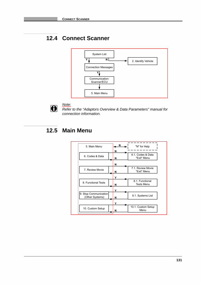
131
CONNECT SCANNER
12.4 Connect Scanner
Note:i Refer to the “Adaptors Overview & Data Parameters” manual for
connection information.
12.5 Main Menu
System List
2. Identify Vehicle
5. Main Menu
Communication:Scanner/ECU
Y N
Connection Messages
Y
6.1. Codes & Data"Exit" Menu6. Codes & Data
N
N
N
N
N
N
Y
N
Y
N
Y
7. Review Movie
8. Functional Tests
9. Stop Communication(Other Systems)
10. Custom Setup
"N" for Help5. Main Menu
7.1. Review Movie"Exit" Menu
8.1. FunctionalTests Menu
9.1. Systems List
10.1. Custom SetupMenu
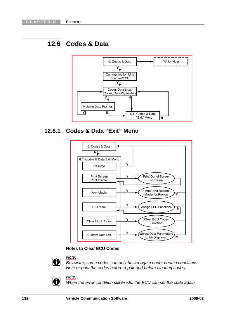
132 Vehicle Communication Software 2009-02
C H A P T E R 12 PEUGEOT
12.6 Codes & Data
12.6.1 Codes & Data “Exit” Menu
Notes to Clear ECU Codes
Note:i Be aware, some codes can only be set again under certain conditions.
Note or print the codes before repair and before clearing codes.
Note:i When the error condition still exists, the ECU can set the code again.
"N" for Help6. Codes & Data
Communication LinkScanner/ECU
Holding Data Frames
Y
Y
N
NY N
Codes/Data Lists:Codes, Data Parameters
6.1. Codes & Data"Exit" Menu
Y
Resume
N
Y
Y
N
Y
N
Y
Y
Print ScreenPrint Frame
Arm Movie
LED Menu
Clear ECU Codes
6.1. Codes & Data Exit Menu
6. Codes & Data
Custom Data List Select Data Parametersto be Displayed
Clear ECU CodesFunction
Assign LED Functions
"Arm" and RecordMovie for Review
Print Out of Screenor Frame
Y
Y
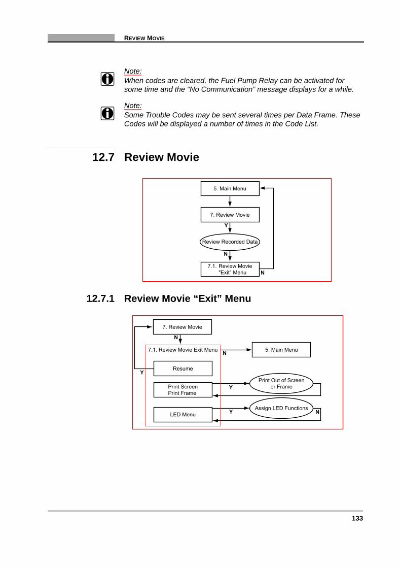
133
REVIEW MOVIE
Note:i When codes are cleared, the Fuel Pump Relay can be activated for
some time and the “No Communication” message displays for a while.
Note:i Some Trouble Codes may be sent several times per Data Frame. These
Codes will be displayed a number of times in the Code List.
12.7 Review Movie
12.7.1 Review Movie “Exit” Menu
7.1. Review Movie"Exit" Menu
5. Main Menu
7. Review Movie
Y
Review Recorded Data
N
N
Resume
N
Y
Y
N
N
Y
Print ScreenPrint Frame
LED Menu
7.1. Review Movie Exit Menu
7. Review Movie
Assign LED Functions
Print Out of Screenor Frame
5. Main Menu
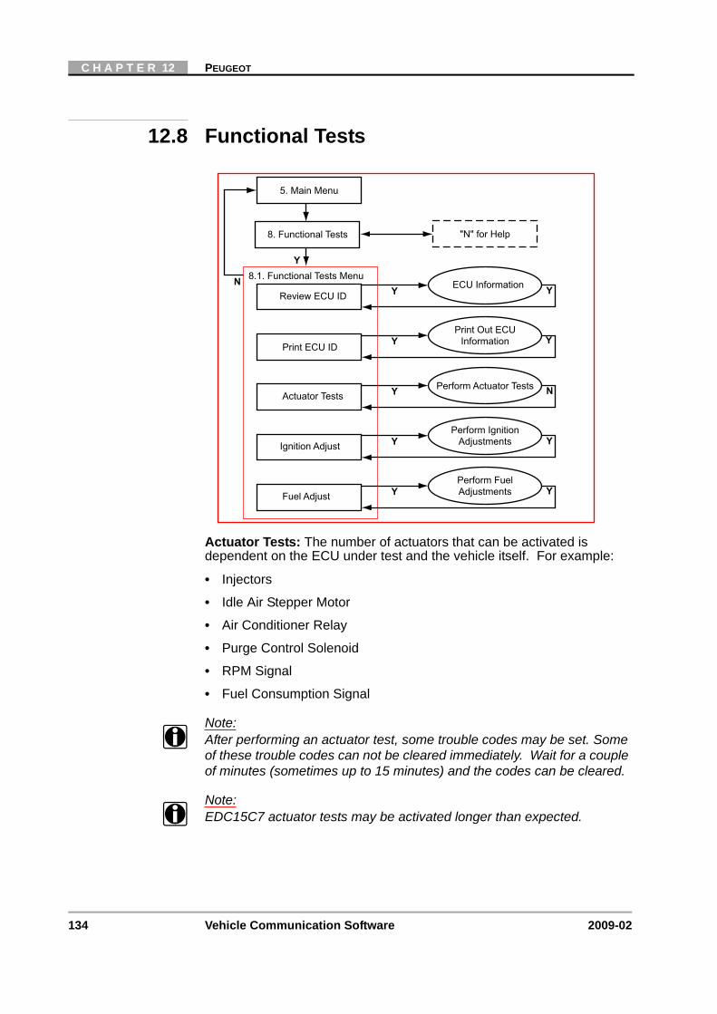
134 Vehicle Communication Software 2009-02
C H A P T E R 12 PEUGEOT
12.8 Functional Tests
Actuator Tests: The number of actuators that can be activated is dependent on the ECU under test and the vehicle itself. For example:
• Injectors
• Idle Air Stepper Motor
• Air Conditioner Relay
• Purge Control Solenoid
• RPM Signal
• Fuel Consumption Signal
Note:i After performing an actuator test, some trouble codes may be set. Some
of these trouble codes can not be cleared immediately. Wait for a couple of minutes (sometimes up to 15 minutes) and the codes can be cleared.
Note:i EDC15C7 actuator tests may be activated longer than expected.
Y
N 8.1. Functional Tests Menu
5. Main Menu
"N" for Help8. Functional Tests
YReview ECU IDECU Information Y
YPrint ECU ID
Print Out ECUInformation
YFuel Adjust
Perform FuelAdjustments Y
YIgnition Adjust
Perform IgnitionAdjustments Y
YActuator TestsPerform Actuator Tests N
Y
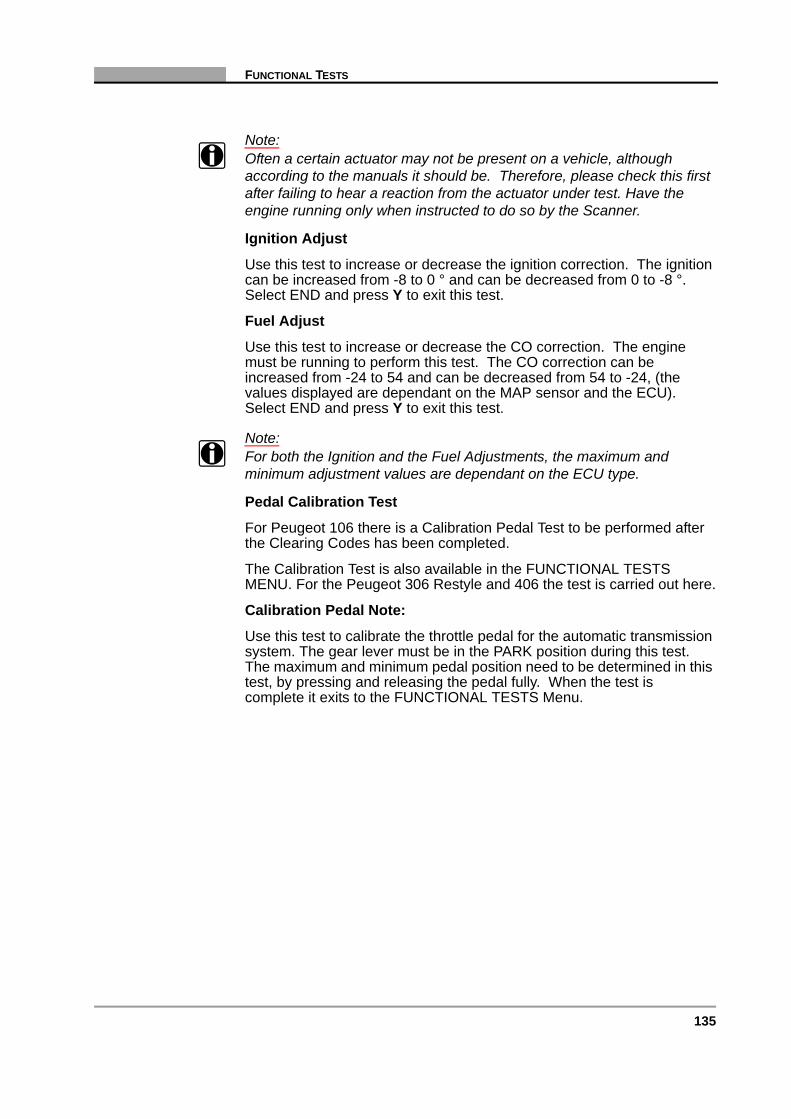
135
FUNCTIONAL TESTS
Note:i Often a certain actuator may not be present on a vehicle, although
according to the manuals it should be. Therefore, please check this first after failing to hear a reaction from the actuator under test. Have the engine running only when instructed to do so by the Scanner.
Ignition Adjust
Use this test to increase or decrease the ignition correction. The ignition can be increased from -8 to 0 ° and can be decreased from 0 to -8 °. Select END and press Y to exit this test.
Fuel Adjust
Use this test to increase or decrease the CO correction. The engine must be running to perform this test. The CO correction can be increased from -24 to 54 and can be decreased from 54 to -24, (the values displayed are dependant on the MAP sensor and the ECU). Select END and press Y to exit this test.
Note:i For both the Ignition and the Fuel Adjustments, the maximum and
minimum adjustment values are dependant on the ECU type.
Pedal Calibration Test
For Peugeot 106 there is a Calibration Pedal Test to be performed after the Clearing Codes has been completed.
The Calibration Test is also available in the FUNCTIONAL TESTS MENU. For the Peugeot 306 Restyle and 406 the test is carried out here.
Calibration Pedal Note:
Use this test to calibrate the throttle pedal for the automatic transmission system. The gear lever must be in the PARK position during this test. The maximum and minimum pedal position need to be determined in this test, by pressing and releasing the pedal fully. When the test is complete it exits to the FUNCTIONAL TESTS Menu.

136 Vehicle Communication Software 2009-02
C H A P T E R 12 PEUGEOT
12.9 Stop Communication, (Other Systems)
Caution:ä The ABS System or ECU can be damaged or disabled if the
Scanner is disconnected before communication has properly stopped. Always return to the Main Menu and select “Stop Communication, (Other Systems)” before disconnecting the Scanner.
Note:i Some Side Airbag systems do not have a separate ECU but are
controlled by the normal Airbag ECU. However, some Side Airbag systems do have a separate ECU, if this is the case, then select “SIDE-AIRBAG LEFT / RIGHT (SEPARATED)” from the System List.
Note:i When testing Automatic Transmission Systems, supporting both 16 and
30 Pin vehicles with Automatic Transmission. If there is a communicating transmission system fitted on the vehicle then choose Y when asked the question “AUTOMATIC TRANSMISSION? PRESS Y OR N” at the vehicle identification stage.
Note:i Also, when testing Automatic Transmission systems the engine MUST
be off and the gearbox must be in Park or Neutral in order to establish communications. Once communication is built up, the engine may be started and the gearbox can be set into Drive.
System ListSelect System
Connection Message
Select System"Main Menu"
2. Identify Vehicle
5. Main Menu
Y N
Y
9. Stop Communication(Other Systems)
"Data Loss"Warning Message
Y N
"N" for Help
"N" for Help
Y
137
CUSTOM SETUP
Note:i When testing the following systems, the Trouble Code list may be
incomplete:
• Bosch ABS 5.3 ESP
• Bosch ABS 8
• Siemens Airbag Through Central
• Temic MK70
Undocumented Code: (especially for 2000+ models).
If undocumented Codes are received it is advisable to check the manuals for the relevant Trouble Code numbers, especially if they are OBD codes on the newer ECUs.
Transmission Systems Note
For Peugeot 106 there is a Calibration Pedal Test to be performed after the Clearing Codes is completed. Use the Functional Tests menu to perform the Calibration Pedal Test.
12.10 Custom Setup
Y
N 10.1. Custom Setup Menu
5. Main Menu
"N" for Help10. Custom Setup
YCommunication SetupSet Baud Rate Y
YImperial/MetricSet Display Units
YAbout
Display SoftwareVersion Information N
YContrast AdjustSet Backlight Automatic
Shut-off Times Y
YLED MenuAssign LED Functions N

138 Vehicle Communication Software 2009-02
C H A P T E R 12 PEUGEOT

139
13 Renault
Overview
This flow diagram represents the basic operation of the software. The numbers beside each item refer to the various headings in this chapter.
1. Start-up Sequence“N” for Help
2. Identify Vehicle
4. Connect Scanner
5. Main Menu TroubleShooter“N” for Help
Y N
3. Select System
10. CustomSetup
10.1. CustomSetup Menu
7. ReviewMovie
9. EndDiagnosis
9.1.Other
Systems
7.1. MovieExit Menu
Codes only
6. Codes &Data Menu Data Only
Data OnlyExit Menu
6.1. Codes& Data
Exit Menu
Codes OnlyExit Menu
8.Functional
Tests
8.1.FunctionalTests Menu
9.2.Systems
List

140 Vehicle Communication Software 2009-02
C H A P T E R 13 RENAULT
13.1 Start-up Sequence
Select Make
Select:
• RENAULT
Select L/R Drive
The correct connector location information displayed is dependent on this selection:
• Scroll to CUSTOM SETUP.
• Select LEFT/RIGHT HAND DRIVE SETUP and press Y to continue. Select LEFT or RIGHT HAND DRIVE, press Y.
• Press N the CUSTOM SETUP menu will be redisplayed.
• Press N again to continue to the Vehicle Identification.
Note:i When testing 1986 to 1999 Vehicles, the Demonstration Program is not
displayed on the menu, however, it can be accessed by selecting a Model Year between 1995 and 2002, then select Model “DEMO LAGUNA”.
Display Test &Copyright Notice
“N” for Help Select Make
Vehicle Systems Training ModeDemonstration
2. Identify Vehicle
Scroll and Select
Y Y
Y
Y
N
Custom SetupSelect L/R Drive

141
IDENTIFY VEHICLE
13.2 Identify Vehicle
13.2.1 Vehicle Selection Notes
Note:i For most vehicles, the model code (Vehicle Type) can be more easily
identified by using the 4th to the 7th characters of the VIN number.
13.2.2 System ID ModeUse if communication problem arise or if the ECU type is unknown.
1. Start-up Sequence
2. Identify Vehicle
Select Model Year
Select Model Type
Select Engine Type
Select Options
3. Select System
Y N
Y
Y
Y N
Y N
N
N
System List
4. Connect Scanner
Instruction Messages
System ID Mode
2. Identify Vehicle
5. Main Menu
Y N
Y
Y
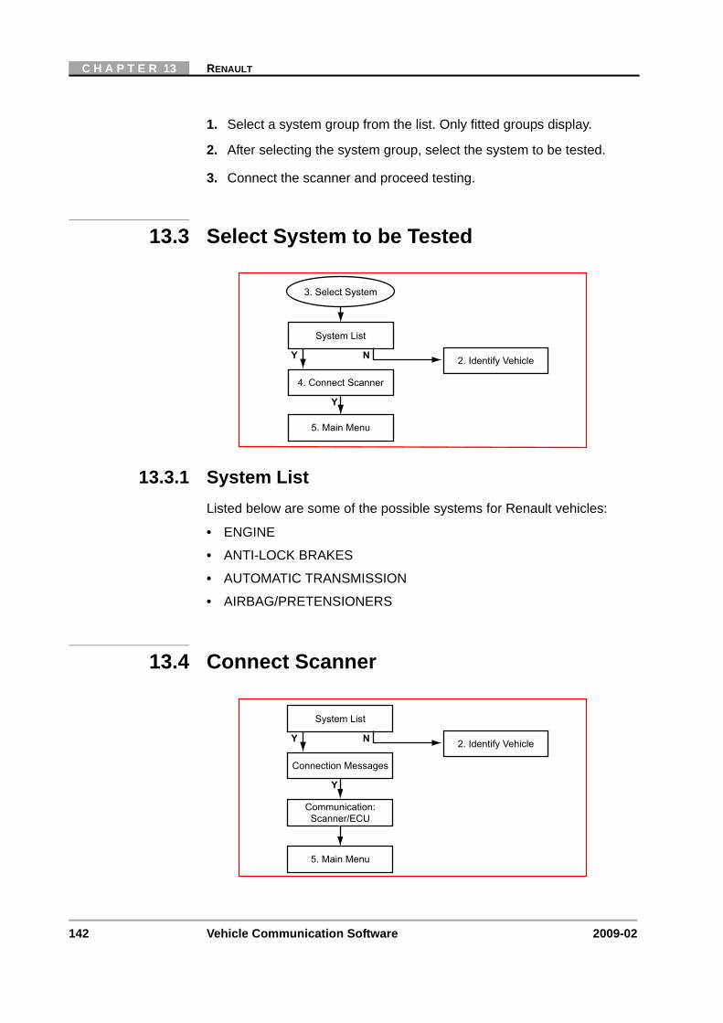
142 Vehicle Communication Software 2009-02
C H A P T E R 13 RENAULT
1. Select a system group from the list. Only fitted groups display.
2. After selecting the system group, select the system to be tested.
3. Connect the scanner and proceed testing.
13.3 Select System to be Tested
13.3.1 System ListListed below are some of the possible systems for Renault vehicles:
• ENGINE
• ANTI-LOCK BRAKES
• AUTOMATIC TRANSMISSION
• AIRBAG/PRETENSIONERS
13.4 Connect Scanner
System List
2. Identify Vehicle
5. Main Menu
4. Connect Scanner
3. Select System
Y N
Y
System List
2. Identify Vehicle
5. Main Menu
Communication:Scanner/ECU
Y N
Connection Messages
Y

143
MAIN MENU
13.5 Main Menu
13.6 Codes & Data
6.1. Codes & Data"Exit" Menu6. Codes & Data
N
N
N
N
N
N
Y
N
Y
N
Y
7. Review Movie
8. Functional Tests
9. End Diagnosis(Other Systems)
10. Custom Setup
"N" for Help5. Main Menu
7.1. Review Movie"Exit" Menu
8.1. FunctionalTests Menu
9.1. Systems List
10.1. Custom SetupMenu
Codes Only "Exit"MenuCodes Only
N
N
Data Only "Exit" MenuData OnlyN
N
N
Y11. Additional Codes
Information11.1. Display Additional
Codes Information
"N" for Help6. Codes & Data
Communication LinkScanner/ECU
Holding Data Frames
Y
Y
N
NY N
Codes/Data Lists:Codes, Data Parameters
6.1. Codes & Data"Exit" Menu
Y

144 Vehicle Communication Software 2009-02
C H A P T E R 13 RENAULT
13.6.1 Data (No Codes)Displays live data parameters, scroll for complete list.
Press N for the Data (No Codes) “Exit Menu.
13.6.2 Codes OnlyDisplays the Diagnostic Trouble Codes (DTCs), scroll for complete list.
Press N for the Codes Only “Exit Menu.
13.6.3 Codes & Data “Exit” Menu
Notes to Clear Codes
Note:i Sometimes a fault code is displayed of a component which is not
installed in the vehicle under test, e.g. a cruise control for Renault. This code can't be cleared. Always make sure the component, the code refers to, is present, when a code can't be cleared.
Note:i Some cleared codes can only be set again under certain circumstances.
Note or print the codes before repair and before clearing codes.
Note:i When the error condition still exists, the ECU can set the code again.
Resume
N
Y
Y
N
Y
N
Y
Y
Print ScreenPrint Frame
Arm Movie
LED Menu
Clear ECU Codes
6.1. Codes & Data Exit Menu
6. Codes & Data
Custom Data List Select Data Parametersto be Displayed
Clear ECU CodesFunction
Assign LED Functions
"Arm" and RecordMovie for Review
Print Out of Screenor Frame
Y
Y

145
REVIEW MOVIE
Note:i The Scanner can display a Trouble Code more than once with the same
additional information. This is because the ECU is sending the same Trouble Code more than once within a single Trouble Codes request.
Note:i If for some reason the Automatic Transmission goes into Limp Home
Mode after clearing codes, the ECU needs to be reset. This can be done by turning the ignition ON (with the engine OFF), depressing and holding down the throttle pedal for 5 seconds, then release the pedal, turn off the ignition and restart the engine.
13.7 Review Movie
13.7.1 Review Movie “Exit” Menu
7.1. Review Movie"Exit" Menu
5. Main Menu
7. Review Movie
Y
Review Recorded Data
N
N
Resume
N
Y
Y
N
N
Y
Print ScreenPrint Frame
LED Menu
7.1. Review Movie Exit Menu
7. Review Movie
Assign LED Functions
Print Out of Screenor Frame
5. Main Menu
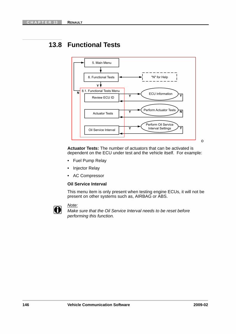
146 Vehicle Communication Software 2009-02
C H A P T E R 13 RENAULT
13.8 Functional Tests
o
Actuator Tests: The number of actuators that can be activated is dependent on the ECU under test and the vehicle itself. For example:
• Fuel Pump Relay
• Injector Relay
• AC Compressor
Oil Service Interval
This menu item is only present when testing engine ECUs, it will not be present on other systems such as, AIRBAG or ABS.
Note:i Make sure that the Oil Service Interval needs to be reset before
performing this function.
Y
N 8.1. Functional Tests Menu
5. Main Menu
"N" for Help8. Functional Tests
YReview ECU IDECU Information Y
YOil Service Interval
Perform Oil ServiceInterval Settings Y
YActuator TestsPerform Actuator Tests N
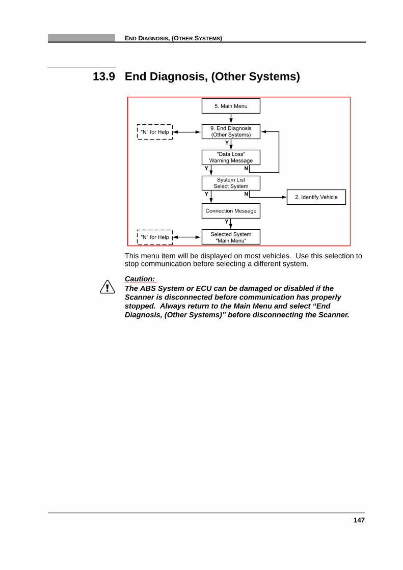
147
END DIAGNOSIS, (OTHER SYSTEMS)
13.9 End Diagnosis, (Other Systems)
This menu item will be displayed on most vehicles. Use this selection to stop communication before selecting a different system.
Caution:ä The ABS System or ECU can be damaged or disabled if the
Scanner is disconnected before communication has properly stopped. Always return to the Main Menu and select “End Diagnosis, (Other Systems)” before disconnecting the Scanner.
System ListSelect System
Connection Message
Selected System"Main Menu"
2. Identify Vehicle
5. Main Menu
Y N
Y
9. End Diagnosis(Other Systems)
"Data Loss"Warning Message
Y N
"N" for Help
"N" for Help
Y
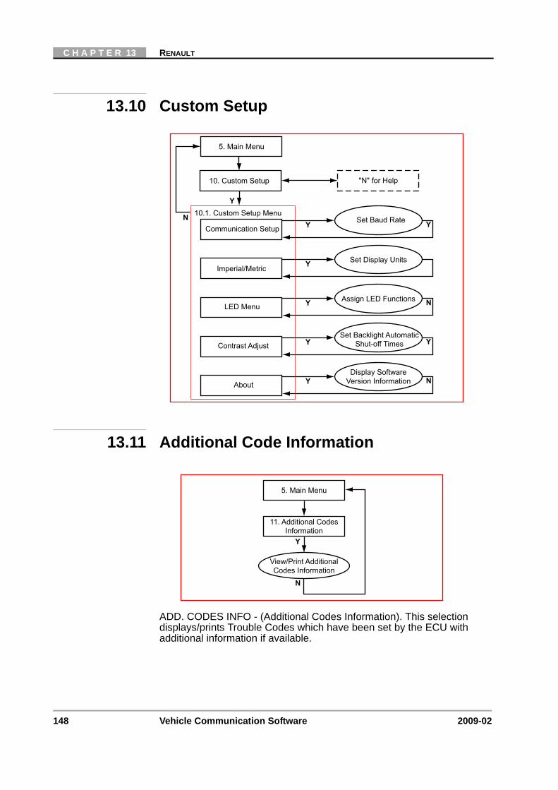
148 Vehicle Communication Software 2009-02
C H A P T E R 13 RENAULT
13.10 Custom Setup
13.11 Additional Code Information
ADD. CODES INFO - (Additional Codes Information). This selection displays/prints Trouble Codes which have been set by the ECU with additional information if available.
Y
N 10.1. Custom Setup Menu
5. Main Menu
"N" for Help10. Custom Setup
YCommunication SetupSet Baud Rate Y
YImperial/MetricSet Display Units
YAbout
Display SoftwareVersion Information N
YContrast AdjustSet Backlight Automatic
Shut-off Times Y
YLED MenuAssign LED Functions N
5. Main Menu
11. Additional CodesInformation
Y
View/Print AdditionalCodes Information
N
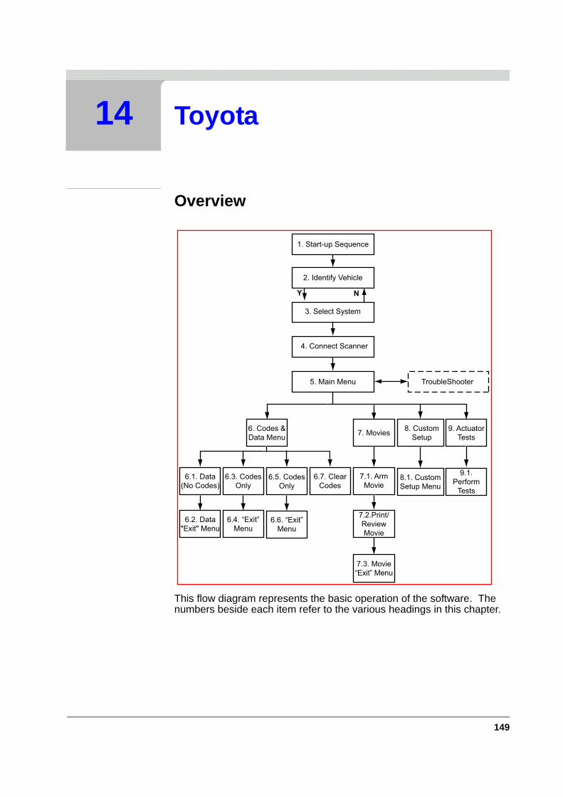
149
14 Toyota
Overview
This flow diagram represents the basic operation of the software. The numbers beside each item refer to the various headings in this chapter.
1. Start-up Sequence
2. Identify Vehicle
4. Connect Scanner
5. Main Menu TroubleShooter
Y N
3. Select System
6.7. ClearCodes
6.4. “Exit”Menu
8. CustomSetup
8.1. CustomSetup Menu
7. Movies
7.1. ArmMovie
7.2.Print/ReviewMovie
7.3. Movie“Exit” Menu
6.3. CodesOnly
6. Codes &Data Menu
6.1. Data(No Codes)
6.2. Data"Exit" Menu
6.6. “Exit”Menu
6.5. CodesOnly
9.1.Perform
Tests
9. ActuatorTests
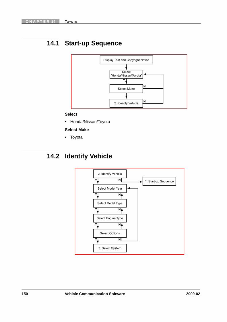
150 Vehicle Communication Software 2009-02
C H A P T E R 14 TOYOTA
14.1 Start-up Sequence
Select
• Honda/Nissan/Toyota
Select Make
• Toyota
14.2 Identify Vehicle
Y
N
Display Test and Copyright Notice
Select"Honda/Nissan/Toyota"
2. Identify Vehicle
Select MakeN
1. Start-up Sequence
2. Identify Vehicle
Select Model Year
Select Model Type
Select Engine Type
Select Options
3. Select System
Y N
Y
Y
Y N
Y N
N
N
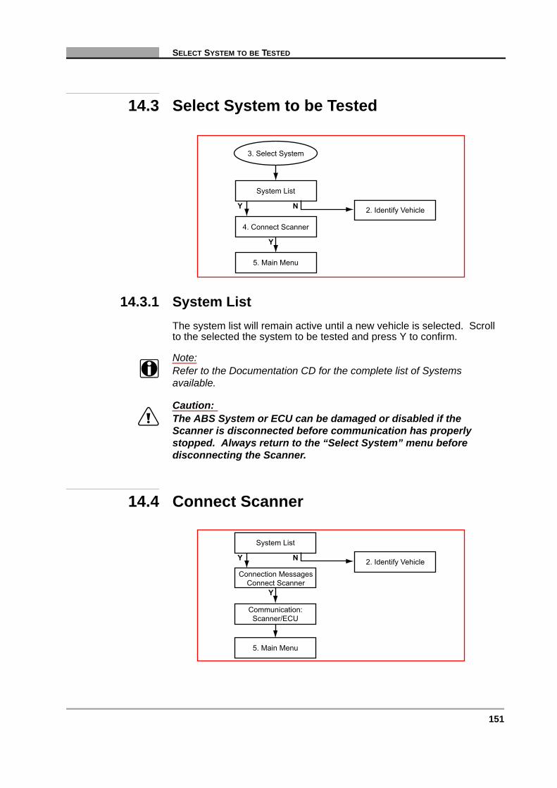
151
SELECT SYSTEM TO BE TESTED
14.3 Select System to be Tested
14.3.1 System ListThe system list will remain active until a new vehicle is selected. Scroll to the selected the system to be tested and press Y to confirm.
Note:i Refer to the Documentation CD for the complete list of Systems
available.
Caution:ä The ABS System or ECU can be damaged or disabled if the
Scanner is disconnected before communication has properly stopped. Always return to the “Select System” menu before disconnecting the Scanner.
14.4 Connect Scanner
System List
2. Identify Vehicle
5. Main Menu
4. Connect Scanner
3. Select System
Y N
Y
System List
2. Identify Vehicle
5. Main Menu
Communication:Scanner/ECU
Y N
Connection MessagesConnect Scanner
Y
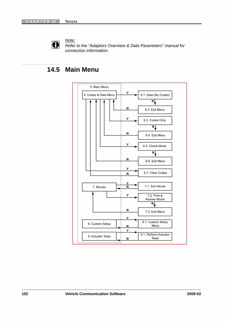
152 Vehicle Communication Software 2009-02
C H A P T E R 14 TOYOTA
Note:i Refer to the “Adaptors Overview & Data Parameters” manual for
connection information.
14.5 Main Menu
7.1. Arm Movie7. Movies NY
N
Y
N
Y
7.3. Exit Menu
8. Custom Setup
7.2. Print &Review Movie
8.1. Custom SetupMenu
5. Main Menu
6.1. Data (No Codes)6. Codes & Data Menu Y
N
N
N
N
6.3. Codes Only
6.4. Exit Menu
6.2. Exit Menu
Y
6.7. Clear CodesYN
N
Y
9. Actuator Tests 9.1. Perform ActuatorTests
N
N
6.5. Check Mode
6.6. Exit Menu
Y
N
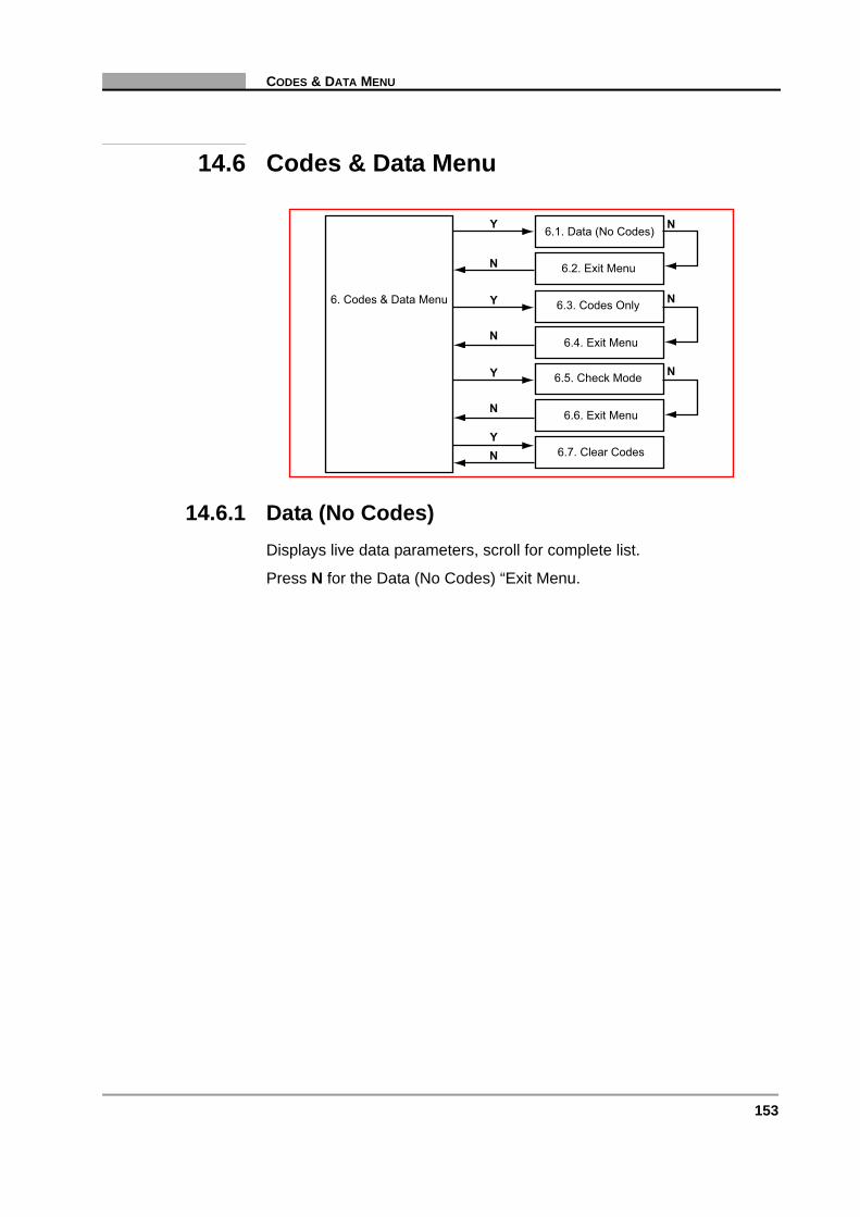
153
CODES & DATA MENU
14.6 Codes & Data Menu
14.6.1 Data (No Codes)Displays live data parameters, scroll for complete list.
Press N for the Data (No Codes) “Exit Menu.
6.1. Data (No Codes)
6. Codes & Data Menu
Y
N
N
N
6.3. Codes Only
6.4. Exit Menu
6.2. Exit Menu
Y
6.7. Clear CodesYN
N
N
6.5. Check Mode
6.6. Exit Menu
Y N
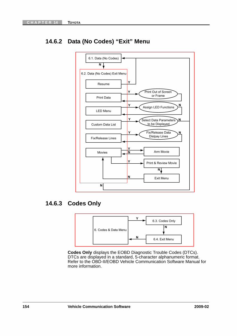
154 Vehicle Communication Software 2009-02
C H A P T E R 14 TOYOTA
14.6.2 Data (No Codes) “Exit” Menu
14.6.3 Codes Only
Codes Only displays the EOBD Diagnostic Trouble Codes (DTCs). DTCs are displayed in a standard, 5-character alphanumeric format. Refer to the OBD-II/EOBD Vehicle Communication Software Manual for more information.
6.2. Data (No Codes) Exit Menu
Resume
Y
N
N
6.1. Data (No Codes)
Y
N
Arm MovieMovies NY
N
Y
Exit Menu
Print & Review Movie
N
Print Data
LED Menu
Custom Data List
Fix/Release Lines
Select Data Parametersto be Displayed
Fix/Release DataDislpay Lines
Assign LED Functions
Print Out of Screenor Frame
Y
Y
Y
N
N
N
Y6.3. Codes Only
6.4. Exit Menu
6. Codes & Data MenuN

155
CODES & DATA MENU
14.6.4 Codes Only “Exit” Menu
14.6.5 Check Mode
Check Mode is used to erase all current Diagnostic Trouble Codes and to check if any new Diagnostic Trouble Codes have been set after erasing.
Note:i Entering the Check Mode will erase DTCs and Freeze Frame Data.
6.4. Codes Only Exit Menu
Resume
Y
N
6.3. Codes Only
Y
Print Codes
Return to Main Menu
Print Out of Codes
Y
N
Y6.5. Check Mode
6.6. Exit Menu
6. Codes & Data MenuN
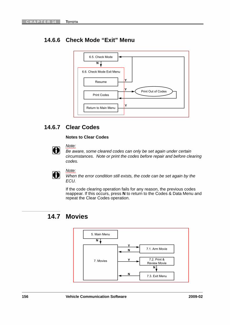
156 Vehicle Communication Software 2009-02
C H A P T E R 14 TOYOTA
14.6.6 Check Mode “Exit” Menu
14.6.7 Clear CodesNotes to Clear Codes
Note:i Be aware, some cleared codes can only be set again under certain
circumstances. Note or print the codes before repair and before clearing codes.
Note:i When the error condition still exists, the code can be set again by the
ECU.
If the code clearing operation fails for any reason, the previous codes reappear. If this occurs, press N to return to the Codes & Data Menu and repeat the Clear Codes operation.
14.7 Movies
6.6. Check Mode Exit Menu
Resume
Y
N
6.5. Check Mode
Y
Print Codes
Return to Main Menu
Print Out of Codes
Y
N
5. Main Menu
7.1. Arm Movie
7. Movies
NY
7.3. Exit Menu
7.2. Print &Review Movie
N
N
Y

157
CUSTOM SETUP
14.7.1 Print/Review Movie “Exit” Menu
14.8 Custom Setup
7.3. Print/Review Movie Exit Menu
Resume
Y
N
7.2. Print/Review Movie
Print ScreenPrint Frame
Fix/Release Lines
Fix/Release DataDislpay Lines
Print Out of Screenor Frame
Y
5. Main MenuN
8.1 Custom Setup Menu
Y
N
5. Main Menu
Communication Setup
Imperial/Metric
Contrast AdjustSet Backlight Automatic
Shut-off Time
Set Display Units
Set Baud Rate
Y
Y
8. Custom Setup
Y
Y
Y
N
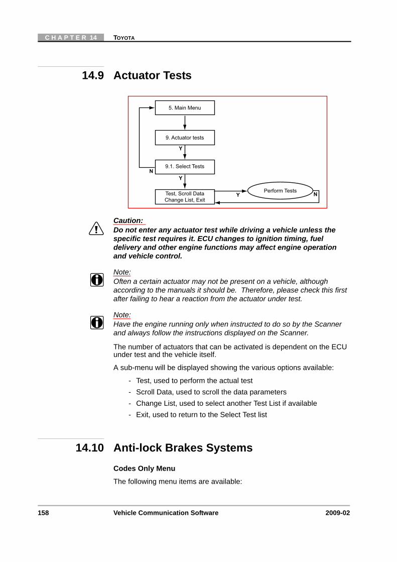
158 Vehicle Communication Software 2009-02
C H A P T E R 14 TOYOTA
14.9 Actuator Tests
Caution:ä Do not enter any actuator test while driving a vehicle unless the
specific test requires it. ECU changes to ignition timing, fuel delivery and other engine functions may affect engine operation and vehicle control.
Note:i Often a certain actuator may not be present on a vehicle, although
according to the manuals it should be. Therefore, please check this first after failing to hear a reaction from the actuator under test.
Note:i Have the engine running only when instructed to do so by the Scanner
and always follow the instructions displayed on the Scanner.
The number of actuators that can be activated is dependent on the ECU under test and the vehicle itself.
A sub-menu will be displayed showing the various options available:
- Test, used to perform the actual test- Scroll Data, used to scroll the data parameters- Change List, used to select another Test List if available- Exit, used to return to the Select Test list
14.10 Anti-lock Brakes SystemsCodes Only Menu
The following menu items are available:
9. Actuator tests
N
9.1. Select Tests
Test, Scroll DataChange List, Exit
Perform TestsY
5. Main Menu
Y
Y
N

159
ANTI-LOCK BRAKES SYSTEMS
• Codes Only, used to display the diagnostic trouble code list.
• Test Mode, used to calibrate the Yaw and G Rate sensor zero point calibration. Carefully follow all instructions displayed. Refer to manufacturers documentation for more information.
• Clear Codes, used to clear codes. Carefully follow all instructions displayed.

160 Vehicle Communication Software 2009-02
C H A P T E R 14 TOYOTA
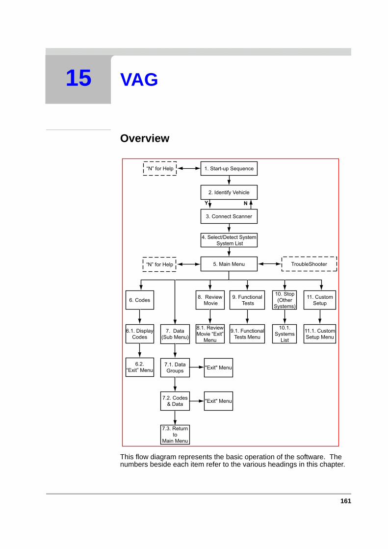
161
15 VAG
Overview
This flow diagram represents the basic operation of the software. The numbers beside each item refer to the various headings in this chapter.
1. Start-up Sequence“N” for Help
2. Identify Vehicle
3. Connect Scanner
5. Main Menu TroubleShooter
11. CustomSetup
11.1. CustomSetup Menu
10. Stop(Other
Systems)
10.1.Systems
List
8. ReviewMovie
8.1. ReviewMovie “Exit”
Menu
“N” for Help
Y N
4. Select/Detect SystemSystem List
6. Codes
6.1. DisplayCodes
6.2.“Exit” Menu
7. Data(Sub Menu)
7.1. DataGroups
9. FunctionalTests
9.1. FunctionalTests Menu
"Exit" Menu
7.3. Returnto
Main Menu
7.2. Codes& Data
"Exit" Menu
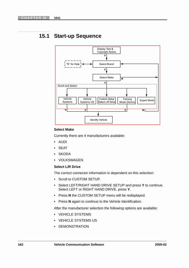
162 Vehicle Communication Software 2009-02
C H A P T E R 15 VAG
15.1 Start-up Sequence
Select Make
Currently there are 4 manufacturers available:
• AUDI
• SEAT
• SKODA
• VOLKSWAGEN
Select L/R Drive
The correct connector information is dependent on this selection:
• Scroll to CUSTOM SETUP.
• Select LEFT/RIGHT HAND DRIVE SETUP and press Y to continue. Select LEFT or RIGHT HAND DRIVE, press Y.
• Press N the CUSTOM SETUP menu will be redisplayed.
• Press N again to continue to the Vehicle Identification.
After the manufacturer selection the following options are available:
• VEHICLE SYSTEMS
• VEHICLE SYSTEMS US
• DEMONSTRATION
Display Test &Copyright Notice
“N” for Help Select Brand
Select Make
VehicleSystems
Custom SetupSelect L/R Drive
Identify Vehicle
Scroll and Select
Y
N
Y
Y
Y
N
TrainingMode (Demo)
Y
Expert ModeVehicleSystems US
Y
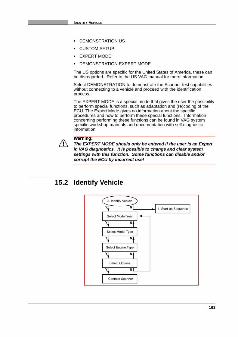
163
IDENTIFY VEHICLE
• DEMONSTRATION US
• CUSTOM SETUP
• EXPERT MODE
• DEMONSTRATION EXPERT MODE
The US options are specific for the United States of America, these can be disregarded. Refer to the US VAG manual for more information.
Select DEMONSTRATION to demonstrate the Scanner test capabilities without connecting to a vehicle and proceed with the identification process.
The EXPERT MODE is a special mode that gives the user the possibility to perform special functions, such as adaptation and (re)coding of the ECU. The Expert Mode gives no information about the specific procedures and how to perform these special functions. Information concerning performing these functions can be found in VAG system specific workshop manuals and documentation with self diagnostic information.
Warning:Warning:ä The EXPERT MODE should only be entered if the user is an Expert
in VAG diagnostics. It is possible to change and clear system settings with this function. Some functions can disable and/or corrupt the ECU by incorrect use!
15.2 Identify Vehicle
1. Start-up Sequence
2. Identify Vehicle
Select Model Year
Select Model Type
Select Engine Type
Select Options
Y N
Y
Y
Y N
Y N
N
N
Connect Scanner

164 Vehicle Communication Software 2009-02
C H A P T E R 15 VAG
15.2.1 System ID ModeUse this mode if communication problem arise or if the vehicle has an unknown ECU type.
1. Select a system group from the list. Only fitted systems groups (engines, lights, seat, etc.) will be displayed.
2. After selecting the system group, select the system to be tested.
3. Connect the scanner and proceed testing.
15.3 Connect Scanner
Note:i See the “Adaptors Overview & Data Parameters” manual for information.
After the connector location message, an “overvoltage on communication lines may be displayed.
System List
4. Connect Scanner
Instruction Messages
System ID Mode
2. Identify Vehicle
5. Main Menu
Y N
Y
Y
System List
2. Identify Vehicle
5. Main Menu
Communication:Scanner/ECU
Y N
Connection MessagesConnect Scanner
Y

165
SELECT SYSTEM TO BE TESTED
If an after market radio is incorrectly installed, there is the possibility that the battery voltage could be connected to the communication line. This can damage the ECU and/or the test equipment if the test equipment is connected to the diagnostic connector. A warning can be displayed.
If the warning is displayed, make sure that the battery voltage is not connected to the communication line. Press N to ignore the message and continue.
15.4 Select System to be Tested
The number of systems that can be tested is dependant on the selected vehicle. However, not all of the systems will be present, some of them are optional and others are mutually exclusive. When an Integrated Immobilizer is present, there will be no Separate Immobilizer present.
The selection for the engine management system is dependent on the selected engine and can be:
• DIESEL PUMP ELECTRONICS, For older diesel systems.
• ENGINE MANAGEMENT MASTER
• ENGINE MANAGEMENT SLAVE, For 8-cylinder Turbo diesel and 12-cylinder petrol engines with 2 ECUs.
• ENGINE MANAGEMENT, For all other engines.
Listed below are some of the possible systems that can be found in VAG vehicles:
• ENGINE MANAGEMENT
• ELECTRONIC INSTRUMENT PANEL
• AIRBAG/PRETENSIONERS
• AUTOMATIC TRANSMISSION
System List
2. Identify Vehicle
Scanner/ECUCommunication
3. Connect Scanner
4. Select System
Y N
Y
5. Main Menu
Y
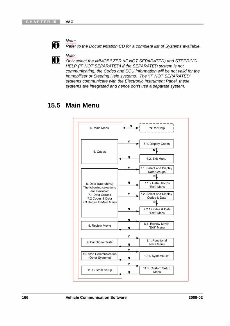
166 Vehicle Communication Software 2009-02
C H A P T E R 15 VAG
Note:i Refer to the Documentation CD for a complete list of Systems available.
Note:i Only select the IMMOBILZER (IF NOT SEPARATED) and STEERING
HELP (IF NOT SEPARATED) if the SEPARATED system is not communicating, the Codes and ECU information will be not valid for the Immobiliser or Steering Help systems. The “IF NOT SEPARATED” systems communicate with the Electronic Instrument Panel, these systems are integrated and hence don’t use a separate system.
15.5 Main Menu
N11. Custom Setup 11.1. Custom Setup
Menu
5. Main Menu
6.1. Display Codes
6. Codes
Y
N
N
N
7.1. Select and DisplayData Groups
7.1.2 Data Groups"Exit" Menu
6.2. Exit Menu
Y
N
Y
9. Functional Tests 9.1. FunctionalTests Menu
N
N
7.2. Select and DisplayCodes & Data
7.2.1 Codes & Data"Exit" Menu
Y
N
6. Data (Sub Menu)The following selections
are available:7.1 Data Groups
7.2 Codes & Data7.3 Return to Main Menu
N
N
8. Review Movie 8.1. Review Movie"Exit" Menu
N
Y10. Stop Communication
(Other Systems) 10.1. Systems List
"N" for Help
Y
N

167
CODES
15.5.1 Data (Sub-menu)The DATA selection from the MAIN MENU is available on most vehicles. The Scanner reads all data available on the ECU data stream. This means that DATA can be used for testing in the workshop as well as road testing. The DATA selection will display the choices DATA GROUPS and CODES & DATA.
When DATA GROUPS are selected, data will be displayed in diagnostic groups to make problem solving easier.
When CODES & DATA is selected, both codes and engine data will be displayed.
15.6 Codes
15.6.1 Display Codes
15.6.2 Codes “Exit” Menu
6.1. Display Codes
Codes/Trouble CodesDisplayed
Communication LinkScanner/ECU
Y
Y
6.2. Codes "Exit" Menu
Y
"N" for HelpN
6.2. Codes "Exit" Menu
Resume
Y
N
6.1. Codes
Y
Print Code/Print All Codes
Clear ECU Codes
Print Out of Codes
Y Clear ECU CodesFunctions
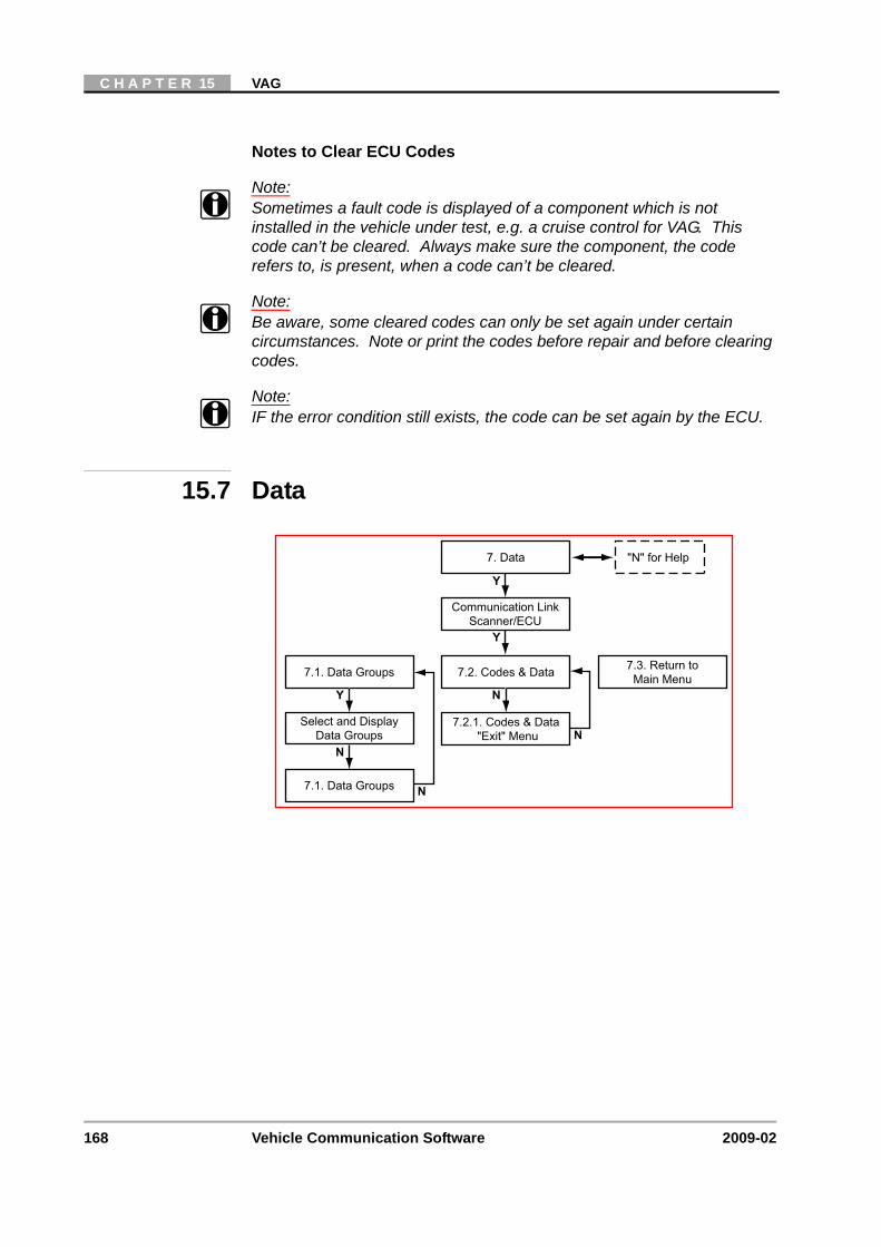
168 Vehicle Communication Software 2009-02
C H A P T E R 15 VAG
Notes to Clear ECU Codes
Note:i Sometimes a fault code is displayed of a component which is not
installed in the vehicle under test, e.g. a cruise control for VAG. This code can’t be cleared. Always make sure the component, the code refers to, is present, when a code can’t be cleared.
Note:i Be aware, some cleared codes can only be set again under certain
circumstances. Note or print the codes before repair and before clearing codes.
Note:i IF the error condition still exists, the code can be set again by the ECU.
15.7 Data
"N" for Help7. Data
Communication LinkScanner/ECU
Y
Y
7.3. Return toMain Menu
N
N
7.1. Data Groups
7.1. Data Groups
Select and DisplayData Groups
Y
7.2.1. Codes & Data"Exit" Menu
7.2. Codes & Data
N
N

169
DATA
15.7.1 Data Groups
15.7.1.1 Data Groups “Exit” Menu
15.7.2 Codes & Data
7.1. Data Groups
7.1.1. Data Groups"Exit" Menu
Display Data Groups
Y
N
Select Data Groups
Y
N
N
7.1.1. Data Groups "Exit" Menu
Resume
Y
N
7.1. Data Groups
Y
Print Group
Amr Movie
Print Out of Codes
Y Arm and RecordMovie for review
"N" for Group Select Menu
"N" for Help7.2. Codes & Data
Communication LinkScanner/ECU
Holding Data Frames
Y
Y
N
NY N
Codes/Data Lists:Codes, Data Parameters
7.2.1. Codes & Data"Exit" Menu
Y

170 Vehicle Communication Software 2009-02
C H A P T E R 15 VAG
15.7.2.1 Codes & Data “Exit” Menu
15.8 Review Movie
Resume
N
Y
Y
N
Y
N
Y
Print ScreenPrint Frame
Arm Movie
LED Menu
7.2.1. Codes & Data Exit Menu
7.2. Codes & Data
Custom Data List Select Data Parametersto be Displayed
Assign LED Functions
"Arm" and RecordMovie for Review
Print Out of Screenor Frame
Y
Y
8.1. Review Movie"Exit" Menu
5. Main Menu
8. Review Movie
Y
Review Recorded Data
N
N
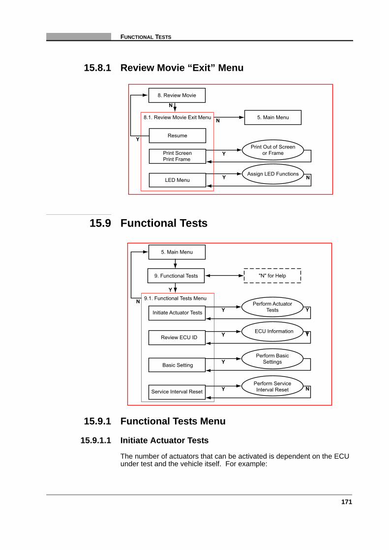
171
FUNCTIONAL TESTS
15.8.1 Review Movie “Exit” Menu
15.9 Functional Tests
15.9.1 Functional Tests Menu
15.9.1.1 Initiate Actuator Tests
The number of actuators that can be activated is dependent on the ECU under test and the vehicle itself. For example:
Resume
N
Y
Y
N
N
Y
Print ScreenPrint Frame
LED Menu
8.1. Review Movie Exit Menu
8. Review Movie
Assign LED Functions
Print Out of Screenor Frame
5. Main Menu
Y
N 9.1. Functional Tests Menu
5. Main Menu
"N" for Help9. Functional Tests
YReview ECU IDECU Information Y
YBasic Setting
Perform BasicSettings
YInitiate Actuator Tests
Perform ActuatorTests Y
YService Interval ResetPerform ServiceInterval Reset N
Y
172 Vehicle Communication Software 2009-02
C H A P T E R 15 VAG
• Fuel Pump Relay
• EVAP CANP Regulator Valve
• Injector Valves, (Odd and Even Cylinders)
• Oxygen Sensor Heater Relay
Warning:Warning:ä “Important Safety Warning”: The Fuel Pump will run continuously
while the Actuator Tests are in progress.
VAG Actuator Test Notes
Note:i Often a certain actuator may not be present on a vehicle, although
according to the manuals it should be. Therefore, please check this first after failing to hear a reaction from the actuator under test.
Note:i Have the engine running only when instructed to do so by the Scanner
and always follow the instructions displayed on the Scanner.
Note:i With some engines, it is very difficult to hear the injectors click. Use a
multimeter or scope to make sure the injectors are activated properly.
Note:i The sequence in which the tests are performed and the availability of the
tests is controlled by the ECU under test.
Note:i On some engines, before the actuator test can be re-initiated the engine
has to run at least 30 seconds prior to the test.
Note:i Some automatic transmission systems do not have actuator tests. If
INITIATE ACTUATOR TESTS is selected the text ACTUATOR TEST NOT POSSIBLE will be displayed.
Note:i A warning can be displayed if the FAN will be started during a test, press
Y to continue.
Note:i Some special actuator tests will not be automatically stopped after 30
seconds. Press N to abort, Y to continue to other possible tests.
15.9.1.2 Basic Setting:
Select the Basic Setting to test and read the conditions.

173
FUNCTIONAL TESTS
Common for all Basic Settings:
- No trouble code present.
For Basic Settings with the engine running:
- Engine running at idle and engine is up to operating temperature.- Make sure that the given conditions are correct!
Note:i Do not attempt to drive the vehicle while in Basic Setting mode.
Note:i Always end the Basic Setting session by selecting OTHER SYSTEMS to
be sure that the settings are stored. Turn the ignition key OFF and wait 60 seconds.
The following Basic Settings can be selected if available:
While testing Engine Management:
A: Throttle Valve Adjuster / Idling Control / Adaptation EPC-System.
In this basic setting the ECU learns the throttle position in with an automatic procedure. If available, also perform the basic setting for kick-down in engine management and for kick down in automatic transmission.
B: Kick-down Function
In this basic setting the ECU learns the kick-down position in for the automatic transmission. The procedure must be followed exactly. (Activate and release kick down, by pressing down the throttle fully).
If available, also perform the basic setting for kick-down in engine management and for kick-down in automatic transmission.
C: Ignition Timing
In basic mode to adjust/check ignition timing, all compensations are off. With the ECU set in basic mode. While in basic mode the ECU will not attempt to compensate for any variation in ignition timing or idle speed. Basic mode will enable these basic settings to be manually adjusted. If basic mode was not enabled, the ECU would immediately compensate for any manual adjustments made. After any adjustments have been made, press N to return engine control to the ECU.
D: Start of Delivery, (Diesel Engines)
In this basic setting the engine will be set in a mode so that the start of delivery can be checked or manually adjusted. The actual value and the minimum and maximum is displayed, (values displayed depends on temperature).
While testing Automatic Transmission Systems:
A: Kick-down Function
174 Vehicle Communication Software 2009-02
C H A P T E R 15 VAG
In this basic setting the ECU learns the kick-down position in for the automatic transmission. The procedure must be followed exactly. (Mostly activate and release kick-down, by pressing down the throttle fully).
If available also perform the basic setting for the Throttle Valve/Adaptation EPC and Kick-down in engine management.
Problems with Basic Settings:
If the adaptation status displays ‘ERROR’ or other problems occur, read the trouble codes for more information. Check the required conditions and try the basic setting again.
15.9.1.3 Selection Towing Hook:
Use this function to select the Towing Hook ON or OFF at the Central Electronic Unit. This function is only applicable for some vehicles with a Central Electronic Unit.
15.9.1.4 Service Interval Reset:
On VAG vehicles with electronic dash boards, this menu item will be available in FUNCTIONAL TESTS.
1. Select SERVICE INTERVAL RESET and press Y.
2. Press N the Scanner will return to the FUNCTIONAL TESTS menu.
3. Return to the MAIN MENU and select OTHER SYSTEMS.
4. From the SYSTEMS LIST select ELECTRONIC INSTRUMENT PANEL.
5. From the “Electronic Instrument Panel”, MAIN MENU select FUNCTIONAL TESTS.
Depending on the type of Electronic Instrument Panel, there are 4 to 9 functions available for Service Resetting.
The service intervals are measured/set/reset in kilometres even when the speedometer shows miles. The Scanner will calculate the equivalence in miles when showing kilometres.
Remember that the service intervals can be changed in steps of 100 or 1000 kilometres only, so it’s not always possibly to set them to a round number of miles. The only exceptions are some new instrument panels, Type H and J, which use Miles as base value.
Depending on the type of Instrument Panel up to three different types of service intervals are available:
• Oil Service Oil Change
• Insp1 Yearly Inspection
• Insp2 2-Yearly Inspection
175
FUNCTIONAL TESTS
Depending on the type of Instrument panel the limit values for the above type of inspections are in kilometres and/or days. The following functions are available:
• RESET SERVICE INTERVAL
• RESET SERVICE INTERVAL OIL(KM)
• RESET SERVICE INTERVAL Insp1(KM)
• RESET SERVICE INTERVAL Insp1(DAYS)
• RESET SERVICE INTERVAL Insp2(DAYS)
• RESET DAYS AND KM AFTER SERVICE
• PRE-SET VALUE OIL(KM)
• PRE-SET VALUE OIL(DAYS)
• PRE-SET VALUE Insp1(KM)
• PRE-SET VALUE Insp1(DAYS)
• PRE-SET VALUE Insp2(KM)
• PRE-SET VALUE MIN OIL(KM)
• PRE-SET VALUE MAX OIL(KM)
• PRE-SET VALUE OIL QUALITY(KM)
• READ, SET KM REMAINING TO OIL SERVICE
• READ, SET DAYS REMAINING TO OIL SERVICE
• READ, SET KM REMAINING TO Insp1
• READ, SET DAYS REMAINING TO Insp1
• READ, RESET KM AFTER OIL SERVICE
• READ, RESET DAYS AFTER OIL SERV.
• READ, RESET DAYS AFTER Insp1
• READ, RESET KM AFTER Insp2
Reset Functions
The RESET functions are used to reset several settings.
The functions are selected by scrolling to the desired one, and pressing Y to select it.
Press Y to continue and follow the instructions displayed or N to abort.
Pre-set Functions
The PRE-SET functions are used to specify the total length in kilometres and or days between the service intervals. These functions only specify the length between intervals, they do not reset the interval.
The functions are selected by scrolling to the desired one, and press Y to select it. The Scanner first will display a warning message (as above).

176 Vehicle Communication Software 2009-02
C H A P T E R 15 VAG
Press Y to continue and follow the instructions displayed or N to abort.
The number displayed is the current value. When it has never been changed, it is the factory setting. This value can be changed by scrolling. Scroll to the correct amount and press Y to accept it.
Read, Set Functions
The READ SET functions can be used to read the kilometres or days since the last service, and to set them to the required value. These functions are only needed when an inspection has been carried out prematurely, that is before the service interval is required.
Basically this function works the same as the PRE-SET functions.
Read, Reset Functions
The READ, RESET functions can be used to read the kilometres or days remaining to the next service, and to reset these values to zero. These functions are only needed when an inspection has been carried out prematurely, that is before the service interval is required.
Basically this function works the same as the PRE-SET functions.
15.9.1.5 Electronic Instrument Panel Types
Currently there are 11 types of Electronic Instrument Panels and the possibilities of each type are described below:
Electronic Instrument Panel, Type A
The available functions are:
• RESET SERVICE INTERVAL OIL(KM)
• RESET SERVICE INTERVAL Insp1(KM)
• RESET SERVICE INTERVAL Insp1(DAYS)
• RESET SERVICE INTERVAL Insp2(DAYS)
After an Oil Service, the following must be used:
• RESET SERVICE INTERVAL OIL(KM)
After an Inspection 1, the following must be used:
• RESET SERVICE INTERVAL OIL(KM)
• RESET SERVICE INTERVAL Insp1(KM)
• RESET SERVICE INTERVAL Insp1(DAYS)
After an Inspection 2, the following must be used:
• RESET SERVICE INTERVAL OIL(KM)
• RESET SERVICE INTERVAL Insp1(KM)
• RESET SERVICE INTERVAL Insp1(DAYS)
• RESET SERVICE INTERVAL Insp2(DAYS)
177
FUNCTIONAL TESTS
Electronic Instrument Panel, Type B
The available functions are:
• RESET SERVICE INTERVAL
• PRE-SET VALUE OIL(KM)
• PRE-SET VALUE Insp1(KM)
• PRE-SET VALUE Insp1(DAYS)
• READ, SET KM REMAINING TO OIL SERVICE
• READ, SET KM REMAINING TO Insp1
• READ, SET DAYS REMAINING TO Insp1
After any service - with the dashboard service indication ON - the following function must be used:
• RESET SERVICE INTERVAL
After an Oil Service - with the dashboard service indication OFF, i.e. a premature service - use the following function:
• READ, SET KM REMAINING TO OIL SERVICE
After an Inspection1 - with the dashboard service indication OFF, i.e. a premature service - use the following functions:
• READ, SET KM REMAINING TO Insp1
• READ, SET DAYS REMAINING TO Insp1
Electronic Instrument Panel, Type C
The available functions are:
• PRE-SET VALUE OIL(KM)
• PRE-SET VALUE OIL(DAYS)
• PRE-SET VALUE Insp1(DAYS)
• PRE-SET VALUE Insp2(KM)
• READ, RESET KM AFTER OIL SERVICE
• READ, RESET DAYS AFTER OIL SERV.
• READ, RESET DAYS AFTER Insp1
• READ, RESET KM AFTER Insp2
After performing the OIL Service, use the following functions:
• READ, RESET KM AFTER OIL SERVICE
• READ, RESET DAYS AFTER OIL SERV.
After performing the Inspection 1, use the following function:
• READ, RESET DAYS AFTER Insp1

178 Vehicle Communication Software 2009-02
C H A P T E R 15 VAG
After performing the Inspection 2, use the following function:
• READ, RESET KM AFTER Insp2
Electronic Instrument Panel, Type D
The available functions are:
• PRE-SET VALUE OIL(KM)
• PRE-SET VALUE Insp1(DAYS)
• READ, RESET KM AFTER OIL SERVICE
• READ, RESET DAYS AFTER Insp1
After an Oil Service, the following function must be used:
• READ, RESET KM AFTER OIL SERVICE
After an Inspection1, the following function must be used:
• READ, RESET DAYS AFTER Insp1
Electronic Instrument Panel, Type E
The available functions are:
• RESET SERVICE INTERVAL
• PRE-SET VALUE OIL(KM)
• PRE-SET VALUE Insp1(DAYS)
• READ, RESET KM AFTER OIL SERVICE
• READ, RESET DAYS AFTER Insp1
After any service - with the dashboard service indication ON - the following function must be used:
• RESET SERVICE INTERVAL
After an Oil Service - with the dashboard service indication OFF, i.e. a premature service - the following function must be used:
• READ, RESET KM AFTER TO OIL SERVICE
After an Inspection1 - with the dashboard service indication OFF, i.e. a premature service - the following function must be used:
• READ, RESET DAYS AFTER Insp1
Electronic Instrument Panel, Type F
This type of Instrument Panel can be programmed to use fixed or flexible Service Intervals. For a fixed interval the Minimum and Maximum distance and the Oil Quality are all set to the same value (15000 km). For flexible Service Intervals the Minimum distance is set to 15000 (km) and the Maximum distance and the Oil Quality are set to 30000, 35000 or 50000 km respectively.
179
FUNCTIONAL TESTS
Use fixed intervals (15000 km, 9300 miles) for vehicles with fixed intervals, (Oil Quality 1).
Use flexible intervals (30000 km, 18600 miles) for petrol engines, (Oil Quality 2).
Use flexible intervals (35000 km, 21700 miles) for 6-cylinder diesel engines, (Oil Quality 3).
Use flexible intervals (50000 km, 31000 miles) for diesel engines, (Oil Quality 4).
Insp1 has a factory setting of 365 days (1 year) for fixed intervals and 730 days (2 years) for flexible intervals.
The available functions are:
• RESET SERVICE INTERVAL
• PRE-SET VALUE OIL QUALITY(KM)
• PRE-SET VALUE MIN OIL(KM)
• PRE-SET VALUE MAX OIL(KM)
• PRE-SET VALUE Insp1(DAYS)
After the Inspection the following functions must be used:
• PRE-SET VALUE OIL QUALITY(KM)
Even when this number stays the same, this value must be changed. It is necessary for the internal housekeeping of the Instrument Panel.
When the Oil Quality has been changed, check Minimum, Maximum and Insp1 for correct values.
• RESET SERVICE INTERVAL
Then use this function to reset the rest of the internal housekeeping of the Instrument Panel.
Electronic Instrument Panel, Type G
This type of Instrument Panel can be programmed to use fixed or flexible Service Intervals. For a fixed interval the Minimum and Maximum distance and the Oil Quality are all set to the same value (15000 km). For flexible Service Intervals the Minimum distance is set to 15000 km and the Maximum distance and the Oil Quality are set to 30000, 35000 or 50000 km respectively.
Use fixed intervals (15000 km, 9300 miles) for vehicles with fixed intervals, (Oil Quality 1).
Use flexible intervals (30000 km, 18600 miles) for petrol engines, (Oil Quality 2).
Use flexible intervals (35000 km, 21700 miles) for 6-cylinder diesel engines, (Oil Quality 3).
Use flexible intervals (50000 km, 31000 miles) for diesel engines, (Oil Quality 4).
180 Vehicle Communication Software 2009-02
C H A P T E R 15 VAG
Insp1 has a factory setting of 365 days (1 year) for fixed intervals and 730 days (2 years) for flexible intervals.
The available functions are:
• RESET SERVICE INTERVAL
• PRE-SET VALUE OIL QUALITY(KM)
• PRE-SET VALUE MIN OIL(KM)
• PRE-SET VALUE MAX OIL(KM)
• PRE-SET VALUE MIN Insp(DAYS)
• PRE-SET VALUE MAX Insp(DAYS)
After the Inspection the following functions must be used:
• PRE-SET VALUE OIL QUALITY(KM)
Even when this number stays the same, this value must be changed. It is necessary for the internal housekeeping of the Instrument Panel. When the Oil Quality has been changed, check Minimum, Maximum Oil and Minimum, Maximum Insp for correct values.
• RESET SERVICE INTERVAL
Then use this function to reset the rest of the internal housekeeping of the Instrument Panel.
Electronic Instrument Panel, Type H
The available functions are:
• RESET SERVICE INTERVAL
• PRE-SET VALUE OIL(MILES)
• PRE-SET VALUE Insp1(DAYS)
• READ, RESET MILES AFTER OIL SERVICE
• READ, RESET DAYS AFTER Insp1
After any service - with the dashboard service indication ON - the following function must be used:
• RESET SERVICE INTERVAL
After an Oil Service - with the dashboard service indication OFF, i.e. a premature service - the following function must be used:
• READ, RESET MILES AFTER OIL SERVICE
After an Inspection1 - with the dashboard service indication OFF, i.e. a premature service - the following function must be used:
• READ, RESET DAYS AFTER Insp1
181
FUNCTIONAL TESTS
Electronic Instrument Panel, Type I
The available functions are:
• RESET SERVICE INTERVAL
• PRE-SET VALUE MIN OIL(KM)
• PRE-SET VALUE MAX OIL(KM)
• PRE-SET VALUE MIN Insp(DAYS)
After the service the following function must be used:
• RESET SERVICE INTERVAL
Electronic Instrument Panel, Type J
This type of Instrument Panel can be programmed to use fixed or flexible Service Intervals. For a fixed interval the Minimum and Maximum distance and the Oil Quality are all set to the same value (15000 km). For flexible Service Intervals the Minimum distance is set to 15000 km and the Maximum distance and the Oil Quality are set to 30000, 35000 or 50000 km respectively.
Use fixed intervals (15000 km, 9300 miles) for vehicles with fixed intervals, (Oil Quality 1).
Use flexible intervals (30000 km, 18600 miles) for petrol engines, (Oil Quality 2).
Use flexible intervals (35000 km, 21700 miles) for 6-cylinder diesel engines, (Oil Quality 3).
Use flexible intervals (50000 km, 31000 miles) for diesel engines (Oil Quality 4).
Insp1 has a factory setting of 365 days (1 year) for fixed intervals and 730 days (2 years) for flexible intervals.
The available functions are:
• RESET SERVICE INTERVAL
• PRE-SET VALUE OIL QUALITY(MILES)
• PRE-SET VALUE MIN OIL(MILES)
• PRE-SET VALUE MAX OIL(MILES)
• PRE-SET VALUE Insp1(DAYS)
After the Inspection the following functions must be used:
• PRE-SET VALUE OIL QUALITY(MILES)
Even when this number stays the same, this value must be changed. It is necessary for the internal housekeeping of the Instrument Panel. When the Oil Quality has been changed, check Minimum, Maximum Oil and Minimum, Maximum Insp for correct values.
• RESET SERVICE INTERVAL
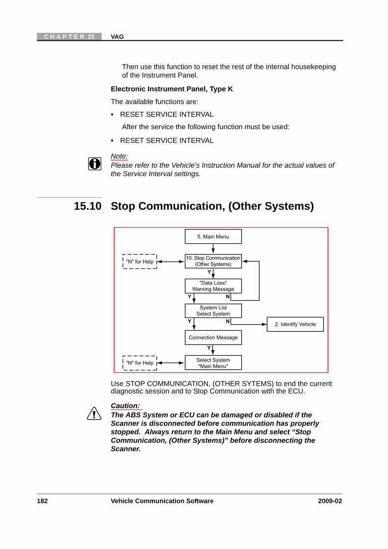
182 Vehicle Communication Software 2009-02
C H A P T E R 15 VAG
Then use this function to reset the rest of the internal housekeeping of the Instrument Panel.
Electronic Instrument Panel, Type K
The available functions are:
• RESET SERVICE INTERVAL
After the service the following function must be used:
• RESET SERVICE INTERVAL
Note:i Please refer to the Vehicle’s Instruction Manual for the actual values of
the Service Interval settings.
15.10 Stop Communication, (Other Systems)
Use STOP COMMUNICATION, (OTHER SYTEMS) to end the current diagnostic session and to Stop Communication with the ECU.
Caution:ä The ABS System or ECU can be damaged or disabled if the
Scanner is disconnected before communication has properly stopped. Always return to the Main Menu and select “Stop Communication, (Other Systems)” before disconnecting the Scanner.
System ListSelect System
Connection Message
Select System"Main Menu"
2. Identify Vehicle
5. Main Menu
Y N
Y
10. Stop Communication(Other Systems)
"Data Loss"Warning Message
Y N
"N" for Help
"N" for Help
Y
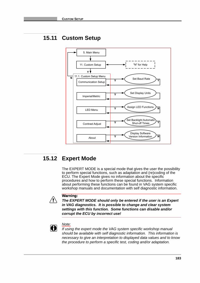
183
CUSTOM SETUP
15.11 Custom Setup
15.12 Expert ModeThe EXPERT MODE is a special mode that gives the user the possibility to perform special functions, such as adaptation and (re)coding of the ECU. The Expert Mode gives no information about the specific procedures and how to perform these special functions. Information about performing these functions can be found in VAG system specific workshop manuals and documentation with self diagnostic information.
Warning:Warning:ä The EXPERT MODE should only be entered if the user is an Expert
in VAG diagnostics. It is possible to change and clear system settings with this function. Some functions can disable and/or corrupt the ECU by incorrect use!
Note:i If using the expert mode the VAG system specific workshop manual
should be available with self diagnostic information. This information is necessary to give an interpretation to displayed data values and to know the procedure to perform a specific test, coding and/or adaptation.
Y
N 11.1. Custom Setup Menu
5. Main Menu
"N" for Help11. Custom Setup
YCommunication SetupSet Baud Rate Y
YImperial/MetricSet Display Units
YAbout
Display SoftwareVersion Information N
YContrast AdjustSet Backlight Automatic
Shut-off Times Y
YLED MenuAssign LED Functions N

184 Vehicle Communication Software 2009-02
C H A P T E R 15 VAG
Select a Manufacturer, select EXPERT MODE or DEMONSTRATION EXPERT MODE to enter the expert mode.
Note:i Before entering the expert mode the communication setup must be set
correctly in the custom setup to have the possibility to print.
Connect the correct diagnostic connector to the vehicle. The following connectors are supported: VW-1, VAG-2, LT-1 and DL-16 with S7. If the connector location is unknown, select the vehicle in VEHICLE SYSTEMS to get the location.
A system menu will be displayed. There are 2 special items and a list of other systems:
15.12.1 Automatic System Test:This test procedure will test all available systems and prints ECU ID and any existing trouble codes. A printer must be connected and must be on-line. Because the Scanner scans all available systems the Automatic System Test can take some time, 10 minutes is not exceptional.
15.12.2 Blink Codes System:This system enters a blink/slow codes menu for reading blink/slow codes. Select codes to read blink codes from a system that has blink codes possibilities.
15.12.3 All Other Systems:After selecting a system, communication will be started and after some warnings the ECU identification will be displayed. After pressing Y the function menu will appear. The functions available depend on the communication protocol, the old protocol or the new KW2000 protocol. Functions that can be executed depend on the system and entry conditions. Some functions will need a log-in or security access before executing the particular function. Not all systems support all functions.
Note:i The 25-IMMOBILIZER (SEPARATED) and 44-STEERING HELP
(SEPARATED) systems can give the following ECU identification: Bitte Adresse 17 eingeben. Although it is possible to continue and select the functions, the information retrieved is not valid and should be discarded. The selected system is integrated in the instrument panel. Please select 17-ELECTRONIC INSTRUMENT PANEL for diagnostics.
The following functions can be available in the list:
01 – READ ECU INFORMATION

185
EXPERT MODE
This function displays the ECU identification string and the ECU coding and WSC (WorkShop Code). Also, some systems will display some extra ECU identification if Y is pressed. Press N to print the ECU information.
02 – CHECK DTC MEMORY
This function displays all current trouble codes present. Press N to enter the print exit menu.
03 – ACTUATOR TESTS
This function activates different actuator tests for about 30 seconds in sequence. The user can abort or continue to the next test. Some tests display a command to the user. For example “Press Brake Pedal”, the user has to press and hold the brake pedal and then press Y to continue.
The sequence, number and type of tests are dictated by the ECU. To perform the actuator tests the entry conditions must be correct. For the correct entry conditions refer to the VAG system specific workshop manual, e.g. engine running or not. On some systems the actuator tests cannot be restarted until the ignition key is switched off for some time.
04 – BASIC SETTINGS
This function can put a system in basic mode or performs a basic setting. This depends on the entered block number (000-255). After entering a valid block number data values or text can be displayed. There is no description of the data value, only the value and unit is displayed. For interpretation of the values refer to the VAG system specific workshop manual.
The system will perform the basic setting now, some data maybe be change during the basic setting. For interpretation of the data and about how to perform a basic setting refer to the VAG system specific workshop manual.
05 – CLEAR DTC MEMORY
This function clears any existing trouble codes and checks if the trouble codes are really cleared. Trouble codes from problems that are still present will not be cleared or will be redisplayed.
06 – STOP COMMUNICATION
This function stops the communication and leaves the Expert Mode.
07 – ECU CODING
This function can change the existing ECU coding by entering a new coding. The range of coding can be 0-127, 0-32767 or 0-1048575. The coding number can tell an ECU about the configuration, e.g. if a cruise control is available or not.
After entering a new coding it will be sent to the ECU and the Scanner will report if the new coding is accepted or not. A coding will not be accepted if it is an unknown number or if an ECU cannot be coded. However the ECU will accept an incorrect coding number.

186 Vehicle Communication Software 2009-02
C H A P T E R 15 VAG
Some special codings require an unlocked ECU. The ECU can be unlocked with a Log-in or Security Access request.
Tyre Pressure Monitoring:
Note:i Always remember the original code, if the code is entered incorrectly, the
“Old” code can always be used.
Enter the individual code digits using the Thumbwheel (Thumbpad), press Y to select the next digit and N to go back to the previous digit.
In this example, this code 20129 means:
- 2 = Audi- 0 = Always “0”- 1 = Antenna, 5 tyres, 4 monitored- 2 = 2.2 bar, loaded vehicle- 9 = 2.9 bar, unloaded vehicle
Note:i Always refer to the vehicle’s Workshop manual for more information.
After the new code is entered always end communication using the “06-STOP COMMUNICATION” function.
If an incorrect code is entered and the software detects an incorrect code message will be displayed.
Once N has been pressed, the correct code can be entered, and the 07-ECU CODING function will be re-displayed.
Press N to return to the Coding ECU menu when prompted.
08 – READ MEASURING VALUE BLOCK
This function displays measuring value blocks. After entering a valid block number data values or text will be displayed. There is no description of the data value, only the value and unit is displayed. For interpretation of the values refer to the VAG system specific workshop manual. Press N to enter the print exit menu. Scroll to change the block number. The displayed data is the actual data received from the ECU.
09 – READ ADC CHANNEL, (not for new KW2000 Protocol)
This function displays data from a single ADC channel. After entering a valid channel number a number from 0 to 65535 will be displayed. Scroll to change the channel number. Press N to enter the print exit menu.
10 – ADAPTATION
This function can change adaptation values from the ECU. After selecting a valid channel the actual adaptation value is displayed. On some adaptation channels, there will be data displayed on the last line. By scrolling or by pressing N for manual input, the new adaptation value

187
EXPERT MODE
can be tested or changed. To exit and store a new value press Y to confirm or press N to abort. Selecting channel 000 will clear all adaptation values after confirmation.
11 – LOGIN REQUEST, (not for new KW2000 Protocol)
This function performs a log-in request to the ECU. After entering a valid log-in code, the ECU is ready to perform a special coding or adaptation function.
11 – ECU CODING 2, (only for new KW2000 Protocol)
This function can change the special ECU coding by entering a new valid coding.
15 – CHECK READINESS CODE SETTING, (not for new KW2000 Protocol)
This function displays the readiness code and information if it is set or not if the system has a readiness code. If the system has no special readiness block sometimes the same information can be found in Function 08 by selecting group 86, and check channel 1.
16 – SECURITY ACCESS, (only for new KW2000 Protocol)
This function performs a security access request to the ECU. After entering a valid code, the ECU is ready to perform a special coding or adaptation function.
Remarks
• Some systems cannot communicate if engine is running.
• Some systems cannot communicate or will loose communication if engine speed exceeds a certain rpm. Refer to the VAG system specific workshop manual.
• Some systems cannot communicate or will loose communication if vehicle speed exceeds a certain speed. e.g. For some ABS above 19 km/h. Refer to the VAG system specific workshop manual.
188 Vehicle Communication Software 2009-02
C H A P T E R 15 VAG

189
16 Volvo
Overview
This flow diagram represents the basic operation of the software. The numbers beside each item refer to the various headings in this chapter.
1. Start-up Sequence“N” for Help
2. Identify Vehicle
4. Connect Scanner
5. Main Menu“N” for Help
Y N
3. Select System
9. CustomSetup
9.1. CustomSetup Menu
7. Data8. Stop(Other
Systems)
8.1.Systems
List
7.1. ExitMenu
6. CodesOnly
6.1. CodesMenu
Troubleshooter
DTCs PendingCodes
6.4. ClearCodes
6.3.Exit Menu

190 Vehicle Communication Software 2009-02
C H A P T E R 16 VOLVO
16.1 Start-up Sequence
Select Make
• Volvo
Select Vehicle/Market Selection or Training Mode
• European LHD
• European RHD
16.1.1 System ID ModeUse if communication problem arise or if the ECU type is unknown.
1. Select a system group from the list. Only fitted groups display.
2. After selecting the system group, select the system to be tested.
Display Test &Copyright Notice
Select MakeSelect Volvo
Vehicle SelectionMarket Selection
System IDMode
Identify Vehicle
Y
NY
N
CustomSetup
TrainingMode
System List
4. Connect Scanner
Instruction Messages
System ID Mode
2. Identify Vehicle
5. Main Menu
Y N
Y
Y

191
IDENTIFY VEHICLE
3. Connect the scanner and proceed testing.
16.2 Identify Vehicle
16.3 Select System to be Tested
1. Start-up Sequence
2. Identify Vehicle
Select Model Year
Select Model Type
Select Engine Type
Select Options
3. Select System
Y N
Y
Y
Y N
Y N
N
N
Vehicle Selection ofMarket Selection
Left Hand Drive orRight Hand Drive
System List
2. Identify Vehicle
5. Main Menu
4. Connect Scanner
3. Select System
Y N
Y

192 Vehicle Communication Software 2009-02
C H A P T E R 16 VOLVO
16.3.1 System ListThe system list will remain active until a new vehicle is selected. Scroll to the selected the system to be tested and press Y to confirm.
Note:i Refer to the Documentation CD for the complete list of Systems
available.
Caution:ä The ABS System or ECU can be damaged or disabled if the
Scanner is disconnected before communication has properly stopped. Always return to the “Select System” menu before disconnecting the Scanner.
16.4 Connect Scanner
Note:i Refer to the “Adaptors Overview & Data Parameters” manual for
connection information.
System List
2. Identify Vehicle
5. Main Menu
Communication:Scanner/ECU
Y N
Connection MessagesConnect Scanner
Y
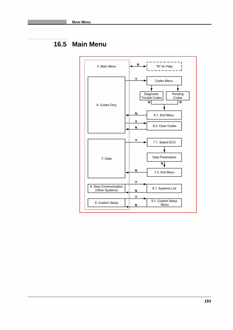
193
MAIN MENU
16.5 Main Menu
5. Main Menu
N
Y8. Stop Communication
(Other Systems) 8.1. Systems List
"N" for Help
N9. Custom Setup 9.1. Custom Setup
Menu
Y
N
Codes Menu
DiagnosticTrouble Codes
Y
N
6.1. Exit Menu
6.2. Clear CodesY
N6. Codes Only
PendingCodes
N
N
7.1. Select ECU
7. Data
Y
N 7.4. Exit Menu
Data Parameters
N
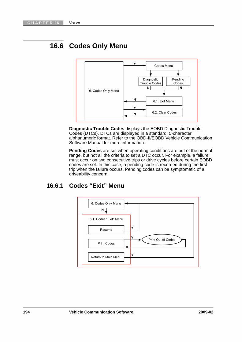
194 Vehicle Communication Software 2009-02
C H A P T E R 16 VOLVO
16.6 Codes Only Menu
Diagnostic Trouble Codes displays the EOBD Diagnostic Trouble Codes (DTCs). DTCs are displayed in a standard, 5-character alphanumeric format. Refer to the OBD-II/EOBD Vehicle Communication Software Manual for more information.
Pending Codes are set when operating conditions are out of the normal range, but not all the criteria to set a DTC occur. For example, a failure must occur on two consecutive trips or drive cycles before certain EOBD codes are set. In this case, a pending code is recorded during the first trip when the failure occurs. Pending codes can be symptomatic of a driveability concern.
16.6.1 Codes “Exit” Menu
Codes Menu
DiagnosticTrouble Codes
Y
N
6.1. Exit Menu
6.2. Clear CodesY
N6. Codes Only Menu
PendingCodes
N
N
6.1. Codes "Exit" Menu
Resume
Y
N
6. Codes Only Menu
Y
Print Codes
Return to Main Menu
Print Out of Codes
Y
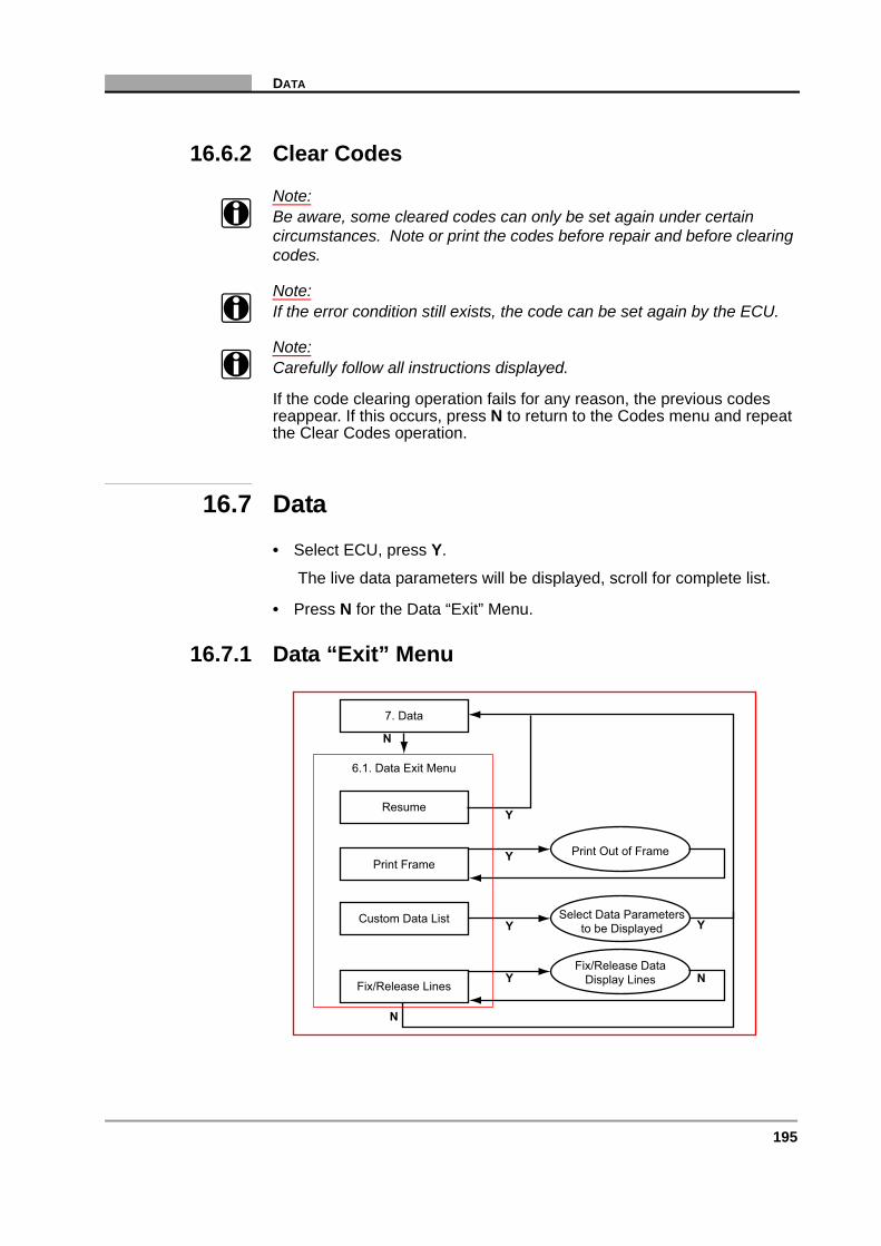
195
DATA
16.6.2 Clear Codes
Note:i Be aware, some cleared codes can only be set again under certain
circumstances. Note or print the codes before repair and before clearing codes.
Note:i If the error condition still exists, the code can be set again by the ECU.
Note:i Carefully follow all instructions displayed.
If the code clearing operation fails for any reason, the previous codes reappear. If this occurs, press N to return to the Codes menu and repeat the Clear Codes operation.
16.7 Data• Select ECU, press Y.
The live data parameters will be displayed, scroll for complete list.
• Press N for the Data “Exit” Menu.
16.7.1 Data “Exit” Menu
Resume
N
Y
Y
N
Y
Y
Print Frame
Custom Data List
Fix/Release Lines
6.1. Data Exit Menu
7. Data
Fix/Release DataDisplay Lines
Select Data Parametersto be Displayed
Print Out of Frame
Y
N

196 Vehicle Communication Software 2009-02
C H A P T E R 16 VOLVO
16.8 Stop Communication, (Other Systems)
Use STOP COMMUNICATION, (OTHER SYTEMS) to end the current diagnostic session and to Stop Communication with the ECU.
Caution:ä The ABS System or ECU can be damaged or disabled if the
Scanner is disconnected before communication has properly stopped. Always return to the Main Menu and select “Stop Communication, (Other Systems)” before disconnecting the Scanner.
16.8.1 Service Interval Reset• Select Service Interval Reset and press Y.
• Carefully follow all instructions displayed.
• Press N to exit.
System ListSelect System
Connection Message
Select System"Main Menu"
2. Identify Vehicle
5. Main Menu
Y N
Y
8. Stop Communication(Other Systems)
"Data Loss"Warning Message
Y N
"N" for Help
"N" for Help
Y

197
CUSTOM SETUP
16.9 Custom Setup
9.1 Custom Setup Menu
Y
N
5. Main Menu
Communication Setup
Imperial/Metric
Contrast AdjustSet Backlight Automatic
Shut-off Time
Set Display Units
Set Baud Rate
Y
Y
9. Custom Setup
Y
Y
Y
N

198 Vehicle Communication Software 2009-02
C H A P T E R 16 VOLVO
Top Related