


Languages
Pages
Legal


Vacuum Deposition System
SAF EM
SAF
Technical SpecificationISO 9001:2008; ISO 14001:2004 Sidrabe Confidential
VACUUM DEPOSITION SYSTEM
SAF EM
Technical Specification
Sidrabe, Inc 17 Krustpils Street Riga, LV–1073 Latvia Phone: +371 67249806 Fax: +371 67139506 E-mail: [email protected]
www.sidrabe.com
Riga, 2016
www.sidrabe.com March 1, 2016 Page 1 of 6

Vacuum Deposition System
SAF EM
S
ISO 9001:2008; ISO 14001:2004 Sidrabe Confidential
AF
Technical Specification
hamber
1. Overview
Vacuum coater SAF EM is an R&D tool for deposition of various multifunctional coatings by magnetron sputtering and thermal evaporation methods. The substrate is 50x50 or 25x25mm solid, flat material that is suitable for vacuum coating. This equipment is designed for scientific research and development works. Vacuum coater SAF EM is a single-csolution based on SAF multifunctional R&D cluster tool concept (http://www.sidrabe.com/cluster-tool ).
2. Specification
2.1. Safety engineering
The coater is designed in accordance with ergonomic principles that ensure access to all parts of the coater for maintenance or replacement. All the equipment is suited for the specific processes within the limits of temperature, pressure and reactive medium requirements. The coater is built in accordance with the safety regulations of the European Commission and European Standards:
• 2006/42/EC (Machinery Directive); • 2006/95/EC (Low Voltage Directive); • EN60204-1:2006+A1:2009 (Safety of Machinery).
The power supplies, electric components and the entire coater have CE marking.
2.2. Electric power
Frequency 50Hz/PEN Voltage 3x400VAC Power 10kW
2.3. Gases
Process gases Ar Air pressure 0.5…0.7MPa
www.sidrabe.com March 1, 2016 Page 2 of 6

Vacuum Deposition System
SAF EM
SAF
Technical SpecificationISO 9001:2008; ISO 14001:2004 Sidrabe Confidential
2.4. Water
Water inlet 10l/min (0.6m3/h) Water pressure 0.25…0.3MPa
2.5. Dimensions of the vacuum chamber (C-shaped stainless steel chamber )
Diameter, mm 520 Height, mm 700
2.6. Dimensions of the coater
2.7. Sample
2.7.1. Dimensions and properties of the sample
Material Glass, metal, or other solid, flat sample, suitable for vacuum process
Dimensions, mm 25 x 25 and 50 x 50
Thickness, mm 1-20 Uncoated area, mm
Up to1.5 from each side
www.sidrabe.com March 1, 2016 Page 3 of 6

Vacuum Deposition System
SAF EM
SAF
Technical SpecificationISO 9001:2008; ISO 14001:2004 Sidrabe Confidential
2.7.2. Sampleholder Material
Copper (St.St., optional)
Dimensions, mm 84 x 84 x 1 (may be changed if necessary)
2.8. Process chamber
2.8.1. Coating
Material for evaporation Au, Ag, Al, Pd, Cu, Ni, etc.
Material for magnetron sputtering
oxides, nitrides, carbon
Uniformity of the coating ± 5 %
2.8.2. Magnetron sputtering
Sputter magnetron 1 pc. Circular target ∅ 2” Changeable magnetron tilt relative to the substrate
± 30 degrees
Power supply with match box 1 pc. Gas feeding system
2.8.3. Thermal evaporation
Evaporator type Evaporator quantity, pc
Resistive evaporators 4
Shield quantity, pc.
1
Volume of crucible
1.2 cm3
Ultimate pressure, Torr Base pressure, Torr
1x10⁻⁶
2x10⁻⁶
Process pressure, Torr
1x10⁻⁵
Evaporator power supply, pc.
1
www.sidrabe.com March 1, 2016 Page 4 of 6
Vacuum Deposition System
SAF EM
ISO 9001:2008; ISO 14001:2004 Sidrabe Confidential
www.sidrabe.com March 1, 2016 Page 5 of 6
SAF
Technical Specification
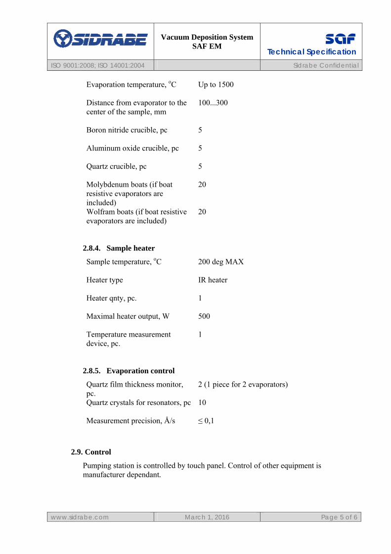
Evaporation temperature, oC Up to 1500
Distance from evaporator to the center of the sample, mm
100...300
Boron nitride crucible, pc Aluminum oxide crucible, pc Quartz crucible, pc Molybdenum boats (if boat resistive evaporators are included) Wolfram boats (if boat resistive evaporators are included)
5 5 5 20 20
2.8.4. Sample heater
Sample temperature, oC
200 deg MAX
Heater type Heater qnty, pc. Maximal heater output, W Temperature measurement device, pc.
IR heater 1 500 1
2.8.5. Evaporation control
Quartz film thickness monitor, pc. Quartz crystals for resonators, pc Measurement precision, Å/s
2 (1 piece for 2 evaporators) 10 ≤ 0,1
2.9. Control
Pumping station is controlled by touch panel. Control of other equipment is manufacturer dependant.

Vacuum Deposition System
SAF EM
ISO 9001:2008; ISO 14001:2004 Sidrabe Confidential
www.sidrabe.com March 1, 2016 Page 6 of 6
SAF
Technical Specification
3. List of components
3.1. Process chamber 3.1.1. Chamber door with two view ports 1 pc. 3.1.2. Flanges with blanks 4 pc. 3.1.3. Flanges with optical window 2 pc. 3.1.4. Sample holder, rotatable, for 1 sample with a possibility to
place a mask 1 pc.
3.1.5. Thermal evaporator 4 pc. 3.1.6. Sputter magnetron (Gencoa) 1 pc. 3.1.7. Bdiscom 200RF AFP power supply with match box BDS
AMN750 1 pc.
3.1.8. Gas feeding system 1 pc. 3.1.9. Quartz film thickness monitor 2 pc. 3.1.10. Sample heater (optional) 3.1.11. Air inlet valve 1 pc. 3.1.12. Pumping: 3.1.12.1. Fore vacuum pump (DUO20 two-stage
mechanical pump (ISO KF 25), Pfeiffer Vacuum or similar from different manufacturer)
1 pc.
3.1.12.2. Turbo pump (HiPace 700 turbomolecular pump DN 160 ISO-K, Pfeiffer Vacuum) 1 pc.
3.1.12.3. Filter DN 16 1 pc. 3.1.12.4. Silencer (ES 25S P/N109873, Alcatel) 1 pc. 3.1.12.5. Throttling valve (TBV-G-600-ISO-160, Nor-
Cal) 1 pc.
3.1.12.6. Pneumatic valve (GVMP-4001-CF, Nor-Cal) 1 pc. 3.1.12.7. EM Valve (XSA3-43S-5DZ-Q, 24 VDC,
SMC) 2 pc.
3.1.12.8. Angle valve (XLAV-25J-A90LA-5LU, SMC) 2 pc. 3.1.12.9. Cold cathode vacuum sensor (KJLC 971,
NW25 KF, Kurt J.Lesker) 1 pc.
3.1.12.10. Digital Pirani type vacuum sensor Digital Pirani sensor (PPT100 DN16 ISO-KF, Pfeiffer Vacuum)
2 pc.
3.1.12.11. Capacitance diaphragm vacuum gauge (100C Heated CDG 100-M11-NW1 (DN16 ISO-KF), Nor-Cal)
1 pc.
3.1.13. Inner lights
Top Related