


![Govt Acctg Recovered] Recovered]](https://static.fdocuments.us/doc/165x107/577d26c61a28ab4e1ea2266a/govt-acctg-recovered-recovered.jpg)


Languages
Pages
Legal


L. Merminga EPAC04 July 5-9 2004Operated by the Southeastern Universities Research Association for the U.S. Department of Energy
Thomas Jefferson National Accelerator Facility Page 1
USPAS Courseon
Recirculated and Energy Recovered Linear Accelerators
G. A. Krafft and L. Merminga
Jefferson Lab
and
Ivan Bazarov
Cornell University
Lecture 16

L. Merminga EPAC04 July 5-9 2004Operated by the Southeastern Universities Research Association for the U.S. Department of Energy
Thomas Jefferson National Accelerator Facility Page 2
ERLERL--Based Free Electron LasersBased Free Electron LasersIntroduction
Operating ERL-FELsJefferson LabJAERIBINP
Planned ERL-FELsKAERI4GLSNHFMLARC-EN-CIEL
An Advanced ERL-FEL ConceptTESLA XFEL-ERL
Summary
Free Electron Lasers
L. Merminga EPAC04 July 5-9 2004Operated by the Southeastern Universities Research Association for the U.S. Department of Energy
Thomas Jefferson National Accelerator Facility Page 3
Free Electron Lasers (FELs) are sources of tunable, coherent radiation at wavelengths varying over a wide range from mm to IR to UV and VUV and to X-rays
An FEL consists of an electron accelerator and a wiggler magnet
Two FEL configurations:
• Oscillator
• Amplifier
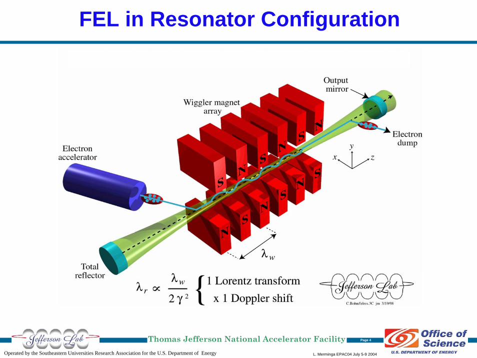
FEL in Resonator Configuration
L. Merminga EPAC04 July 5-9 2004Operated by the Southeastern Universities Research Association for the U.S. Department of Energy
Thomas Jefferson National Accelerator Facility Page 4

FEL in Amplifier Configuration
L. Merminga EPAC04 July 5-9 2004Operated by the Southeastern Universities Research Association for the U.S. Department of Energy
Thomas Jefferson National Accelerator Facility Page 5
Electron Beam Requirements
L. Merminga EPAC04 July 5-9 2004Operated by the Southeastern Universities Research Association for the U.S. Department of Energy
Thomas Jefferson National Accelerator Facility Page 6
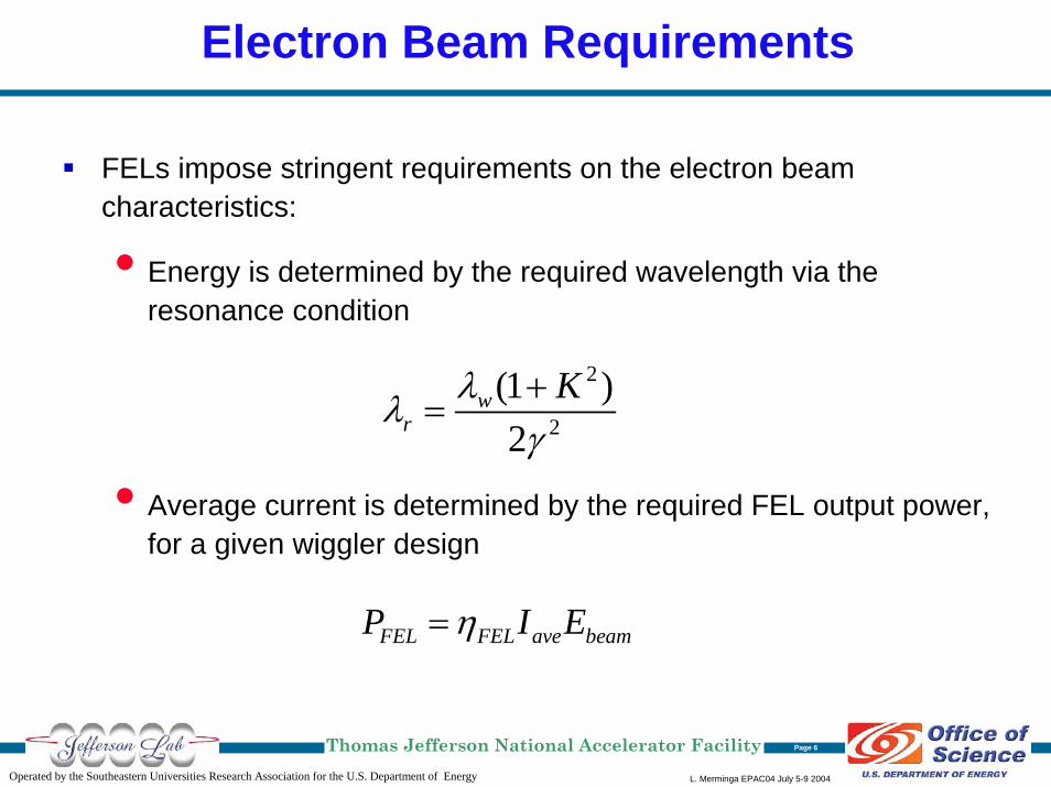
FELs impose stringent requirements on the electron beam characteristics:
• Energy is determined by the required wavelength via the resonance condition
• Average current is determined by the required FEL output power, for a given wiggler design
2
2
(1 )2
wr
Kλλγ+
=
FEL FEL ave beamP I Eη=

Electron Beam Requirements (Cont’d)
L. Merminga EPAC04 July 5-9 2004Operated by the Southeastern Universities Research Association for the U.S. Department of Energy
Thomas Jefferson National Accelerator Facility Page 7
• Bunch charge and bunch length are determined by the peak currentrequired for sufficient gain
• Emittance and energy spread are determined by the FEL interaction:
→ For optimum coupling, the optical beam must overlap the
electron beam through the wiggler
→ To ensure all electrons radiate within the bandwidth of the
FEL
4rλεπ
≤
41 (osc.) 10 (ampl.)5
E E
wE N Eσ σ −≤ ≤ ,
Operating ERL-FELs
L. Merminga EPAC04 July 5-9 2004Operated by the Southeastern Universities Research Association for the U.S. Department of Energy
Thomas Jefferson National Accelerator Facility Page 8
Jefferson Lab FEL
JAERI FEL
BINP FEL

L. Merminga EPAC04 July 5-9 2004Operated by the Southeastern Universities Research Association for the U.S. Department of Energy
Thomas Jefferson National Accelerator Facility Page 9
JLab 10kW IR FEL and 1 kW UV FELInjector
Beam dump
IR wiggler
Superconducting rf linac
UV wiggler
Injector
Beam dump
IR wiggler
Superconducting rf linac
UV wiggler
Output Light Parameters IR UV Wavelength range (microns) 1.5 - 14 0.25 - 1Bunch Length (FWHM psec) 0.2 - 2 0.2 - 2Laser power / pulse (microJoules) 100 - 300 25
Laser power (kW) >10 > 1Rep. Rate (cw operation, MHz) 4.7 – 75 4.7 – 75
Electron Beam Parameters IR UV
Energy (MeV) 80-200 200Accelerator frequency (MHz) 1500 1500Charge per bunch (pC) 135 135Average current (mA) 10 5Peak Current (A) 270 270Beam Power (kW) 2000 1000Energy Spread (%) 0.50 0.13Normalized emittance (mm-mrad) <30 <11
Induced energy spread (full) 10% 5%

L. Merminga EPAC04 July 5-9 2004Operated by the Southeastern Universities Research Association for the U.S. Department of Energy
Thomas Jefferson National Accelerator Facility Page 10
JAERI ERL-FEL
Output Light Parameters Achieved GoalWavelength range (microns) 22 22Bunch Length (FWHM psec) 15 6Laser power / pulse (microJoules) 10 120
Laser power (kW) 0.1 10Rep. Rate ( MHz) 10.4 83.2
Macropulse format10ms
10HzCW
Electron Beam Parameters Achieved GoalEnergy (MeV) 17 16.4Accelerator frequency (MHz) 500 500Charge per bunch (pC) 500 500Average current (mA) 5 40Peak Current (A) 33 83Beam Power (kW) 85 656Energy Spread (%) ~0.5 ~0.5Normalized emittance (mm-mrad) ~40 ~40Induced energy spread (full) ~3% ~3%

L. Merminga EPAC04 July 5-9 2004Operated by the Southeastern Universities Research Association for the U.S. Department of Energy
Thomas Jefferson National Accelerator Facility Page 11
BINP Recuperator FEL
Output Light Parameters IR Wavelength range (microns) 120-180Bunch Length (FWHM psec) 50Laser power / pulse (microJoules) 9Laser power (kW) 0.2Rep. Rate (cw operation, MHz) 22.5
Electron Beam Parameters IR
Energy (MeV) 12Accelerator frequency (MHz) 180Charge per bunch (pC) 900Average current (mA) 20Peak Current (A) 10Beam Power (kW) 240Energy Spread (%) 0.2Normalized emittance (mm-mrad) 20
180 MHz NC RF
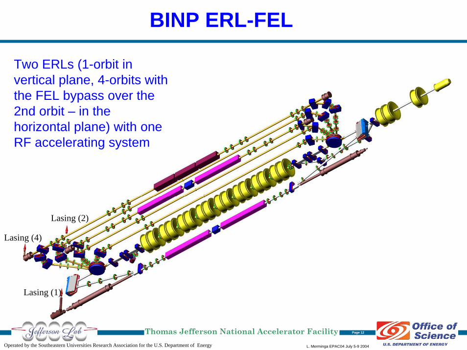
BINP ERL-FEL
L. Merminga EPAC04 July 5-9 2004Operated by the Southeastern Universities Research Association for the U.S. Department of Energy
Thomas Jefferson National Accelerator Facility Page 12
Lasing (1)
Lasing (4)
Lasing (2)
Two ERLs (1-orbit in vertical plane, 4-orbits with the FEL bypass over the 2nd orbit – in the horizontal plane) with one RF accelerating system
L. Merminga EPAC04 July 5-9 2004Operated by the Southeastern Universities Research Association for the U.S. Department of Energy
Thomas Jefferson National Accelerator Facility Page 13
Planned ERL-FELs
KAERI FEL
4GLS
NHMFL
ARC-EN-CIEL
L. Merminga EPAC04 July 5-9 2004Operated by the Southeastern Universities Research Association for the U.S. Department of Energy
Thomas Jefferson National Accelerator Facility Page 14
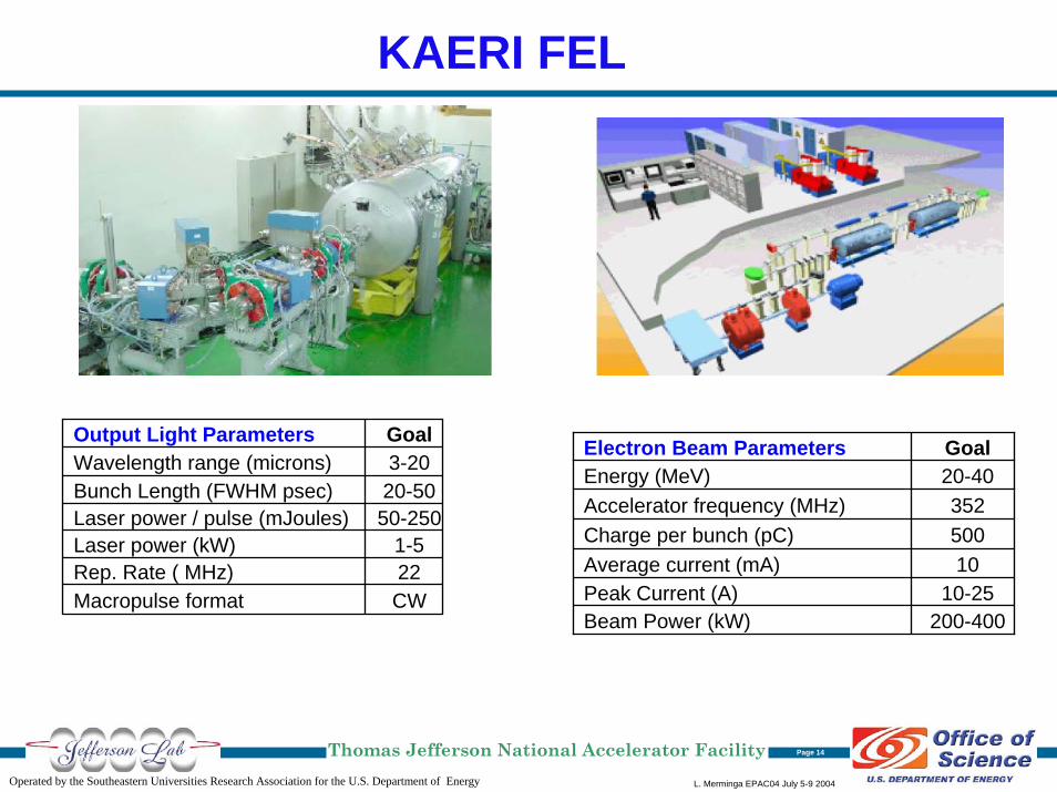
KAERI FEL
Output Light Parameters GoalWavelength range (microns) 3-20Bunch Length (FWHM psec) 20-50Laser power / pulse (mJoules) 50-250Laser power (kW) 1-5Rep. Rate ( MHz) 22Macropulse format CW
Electron Beam Parameters GoalEnergy (MeV) 20-40Accelerator frequency (MHz) 352Charge per bunch (pC) 500Average current (mA) 10Peak Current (A) 10-25Beam Power (kW) 200-400
L. Merminga EPAC04 July 5-9 2004Operated by the Southeastern Universities Research Association for the U.S. Department of Energy
Thomas Jefferson National Accelerator Facility Page 15
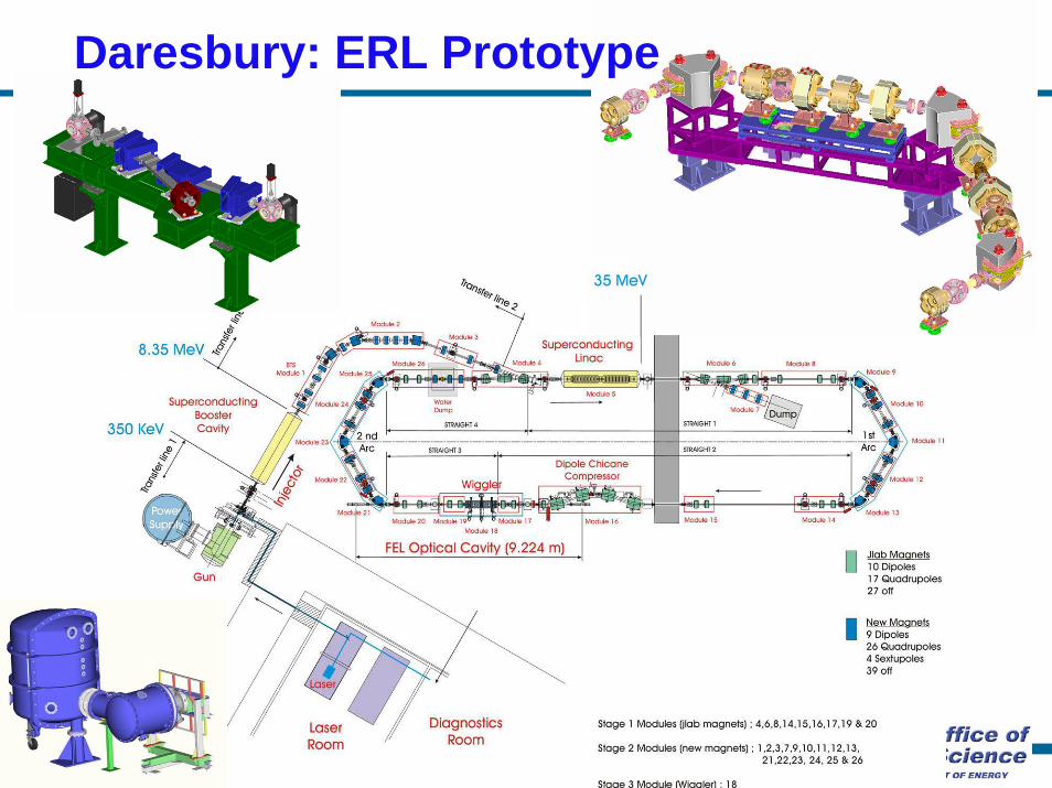
End arc
Daresbury: ERL Prototype
L. Merminga EPAC04 July 5-9 2004Operated by the Southeastern Universities Research Association for the U.S. Department of Energy
Thomas Jefferson National Accelerator Facility Page 16
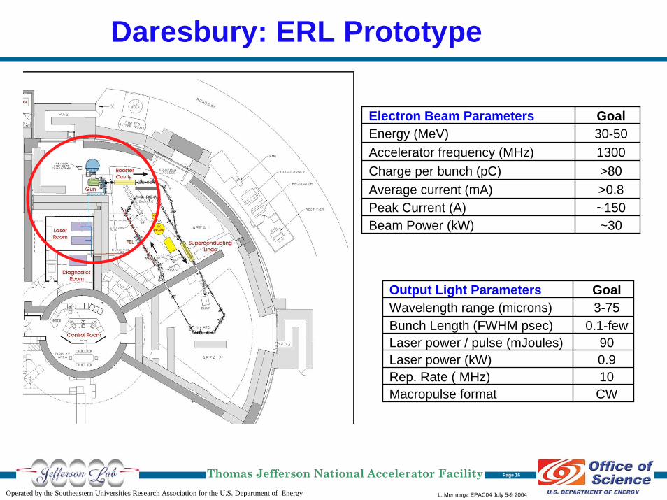
Daresbury: ERL Prototype
Electron Beam Parameters GoalEnergy (MeV) 30-50Accelerator frequency (MHz) 1300Charge per bunch (pC) >80Average current (mA) >0.8Peak Current (A) ~150Beam Power (kW) ~30
Output Light Parameters GoalWavelength range (microns) 3-75Bunch Length (FWHM psec) 0.1-fewLaser power / pulse (mJoules) 90Laser power (kW) 0.9Rep. Rate ( MHz) 10Macropulse format CW
L. Merminga EPAC04 July 5-9 2004Operated by the Southeastern Universities Research Association for the U.S. Department of Energy
Thomas Jefferson National Accelerator Facility Page 17
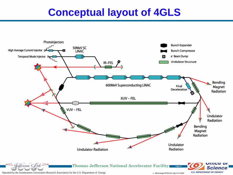
Conceptual layout of 4GLS

L. Merminga EPAC04 July 5-9 2004Operated by the Southeastern Universities Research Association for the U.S. Department of Energy
Thomas Jefferson National Accelerator Facility Page 18
National High Magnetic Field Laboratory (NHMFL)
Proposal for a Concept and Engineering Design submitted to NSF in January 2005, with UCSB and JLab as partners. The goal is to produce a facility that can combine high magnetic fields (~50T) and intense electromagnetic radiation spanning the wavelength range of 2 mm to 2 mm.
Electron Beam Parameters GoalEnergy (MeV) 60Accelerator frequency (MHz) 1500Charge per bunch (pC) 135Average current (mA) 5Peak Current (A) 200Beam Power (kW) 300
Output Light Parameters GoalWavelength range (microns) 2-100Bunch Length (FWHM psec) 0.5-fewLaser power / pulse (mJoules) ~25Laser power (kW) ~1Rep. Rate ( MHz) 37.5Macropulse format CW
L. Merminga EPAC04 July 5-9 2004Operated by the Southeastern Universities Research Association for the U.S. Department of Energy
Thomas Jefferson National Accelerator Facility Page 19
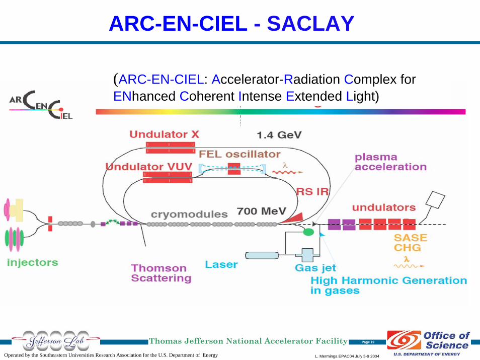
ARC-EN-CIEL - SACLAY
(ARC-EN-CIEL: Accelerator-Radiation Complex for ENhanced Coherent Intense Extended Light)
An Advanced ERL-FEL Concept
L. Merminga EPAC04 July 5-9 2004Operated by the Southeastern Universities Research Association for the U.S. Department of Energy
Thomas Jefferson National Accelerator Facility Page 20
TESLA XFEL ERL

TESLA XFEL ERL
L. Merminga EPAC04 July 5-9 2004Operated by the Southeastern Universities Research Association for the U.S. Department of Energy
Thomas Jefferson National Accelerator Facility Page 21
Performance Goals for SASE FEL Radiation at the DESY XFEL
Photon energy 12.4 – 0.2 keVPhoton wavelength 0.1 – 6.4 nmPeak power 24 – 135 GWAverage power 66 – 800 W# photons/ pulse 1 – 430 x 1012
Peak brilliance 5.4 – 0.6 x 1033 **
Average brilliance 1.6 – 0.3 x 1025 **
** in units of photons / (s mrad2 mm2 0.1% b.w.)
Proposed ER operation would have a rep rate of 1 MHz instead of DESY XFEL rep rate of 10 Hz, increasing the average power and brilliance by a factor of 105
L. Merminga EPAC04 July 5-9 2004Operated by the Southeastern Universities Research Association for the U.S. Department of Energy
Thomas Jefferson National Accelerator Facility Page 22
At a 1 MHz rep rate there are 6 bunches in the ER Linac at a given time, thus 12 collision locations separated by 150The proposed solution is to avoid collisions altogether!
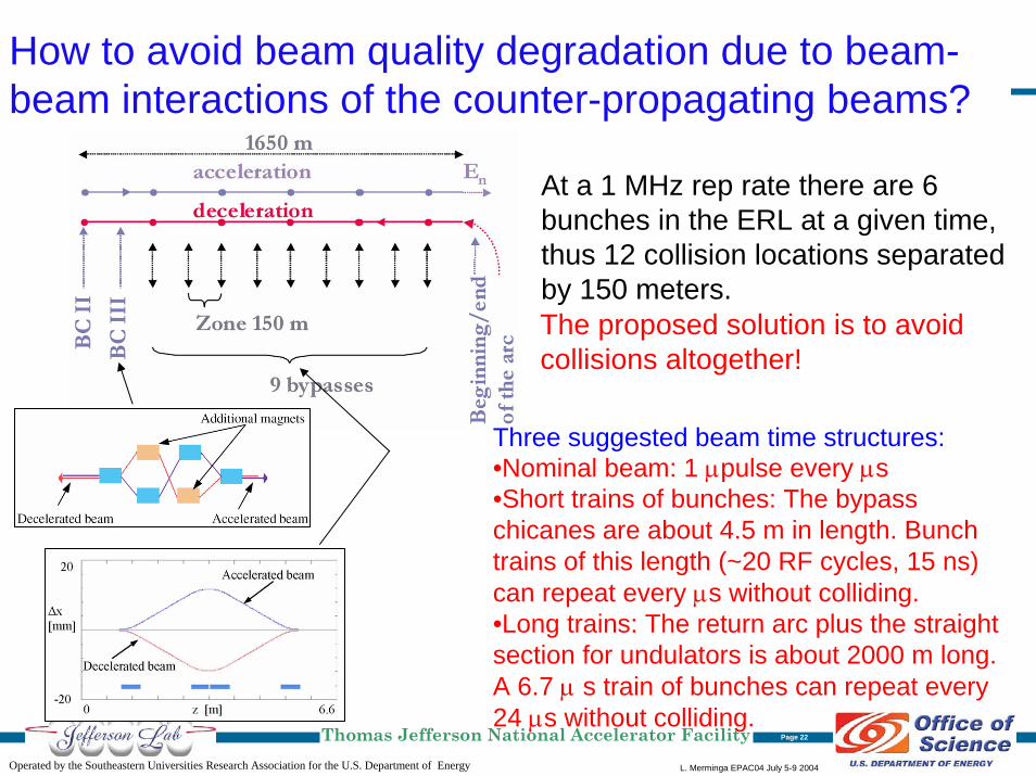
How to avoid beam quality degradation due to beam-beam interactions of the counter-propagating beams?
At a 1 MHz rep rate there are 6 bunches in the ERL at a given time, thus 12 collision locations separated by 150 meters.
Three suggested beam time structures:•Nominal beam: 1 µpulse every µs•Short trains of bunches: The bypass chicanes are about 4.5 m in length. Bunch trains of this length (~20 RF cycles, 15 ns) can repeat every µs without colliding.•Long trains: The return arc plus the straight section for undulators is about 2000 m long. A 6.7 µ s train of bunches can repeat every 24 µs without colliding.
L. Merminga EPAC04 July 5-9 2004Operated by the Southeastern Universities Research Association for the U.S. Department of Energy
Thomas Jefferson National Accelerator Facility Page 23
Summary: Summary: A bright futureA bright future
ERLs provide a powerful and elegant paradigm for high average power free electron lasers.
The pioneering ERL FELs have established the fundamental principles of ERLs.
The multitude of ERL-FEL projects and proposals worldwide promises an exciting next decade as:
• Three currently operating ERL-FELs will reach higher performance
• At least four more are in serious planning stages and will likely be constructed
• New advanced concepts are being explored
Many thanks to Todd Smith for providing much of the material.
Top Related