


Languages
Pages
Legal


6/9/2014
1
Terry M. Barr, P.E., CFM
Corey Branson, P.E., CFM
Halff Associates, Inc.
TFMA Spring Conference
Irving, TX
May 29, 2014
Presentation Agenda Project Background
Steady Modeling Approach
Specific Areas of Concern
ICM Model Construction
Pros and Cons
Comparison to HMS/RAS
Flood Mitigation
Questions
Project Location
6/9/2014
2
Project Background Approx. 3.3 Sq. Miles
Wildcat 1.8 sq. mi.
Dunbar 1.5 sq. mi.
Drains to Lake Arlington
Primarily Residential
Single Family
Low Density Residential
Industrial
Parks and Institutional
Several Areas with Frequent Flooding
Project Background FW Open Channel Studies
FEMA Effective Zone AE
Small Section of Zone A
Established Floodway
Study Intent
Update Floodplain and Floodway based on recent data
Evaluate Improvement Alternatives
Recommend CIP
Steady Modeling Approach Hydrologic Analysis (HEC-HMS)
Basin Delineation, Parameter Development
NRCS Loss and Unit Hydrograph Methods
Modified-Puls Routing
Flow Diversion

6/9/2014
3
Steady Modeling Approach Hydraulic Modeling (HEC-RAS)
Section Layout Based on Assumed Flow Direction
Split Flow Optimization at Mt. Tabor
Roughness Values Based on Aerials and Field Observation
Structures Surveyed for Accuracy
Areas of Concern Overflow at Ramey Ave
Overflow at Crenshaw
Lateral Spill at Mt. Tabor
Left Overbank Flow
Flow Along Berry St.
Flow Under IH-820E
Steady Modeling Limitations Flow in Multiple Directions
Parallel/Split Channels
Overland Flow Challenges
Volume and Detention
Calculation Assumptions
(Standard Step vs Dynamic)
Mapping Assumptions
What are the limitations of traditional methods?
Traditional drainage calculations require the engineer to make assumptions about these issues…these may be over-simplified, very
conservative, or just plain wrong.

6/9/2014
4
Benefits of 2D Analysis Hydrology – Uses full hydrograph
Account for differences in timing
Evaluate surface flow patterns accurately
Hydraulics – Realistic 1D/2D interaction
Complex overland flow directions
Break over from one stream to another
Storage in low-lying areas and impoundments
Split flow situations and relief channels
Look at the system as a whole
Gain a better understanding of flow patterns for HMS/RAS
Optimize the solutions to reduce project costs
InfoWorks ICM Model Integrated Catchment Modeling – Combines Urban Storm
Sewer and Riverine Flow in 1D/2D Hydrodynamic Model
Capabilities – Closed Conduit and Overland Interaction
1D Storm Sewer
1D Stream Channels
2D Overland Flow
Hydrology
ICM Model Construction Ground Model Import
Construct River Reaches
Add Flow Information
Add Roughness Polygons
Add Voids
Add Breaklines
Generate 2D Mesh
Add Bridges/Culverts
Run/Troubleshoot
Dynamic River Modeling is an Iterative Process… …Fix, Run, Crash, Repeat

6/9/2014
5
If the Model Runs Then It is Good
Check and Re-Check
Volume Balance
Stability
Engineering Judgment
Do the Results Make Sense?
It is a Black Box (Don’t Know How It Gets the Answer)
Run Hand Calculations
Runs the Same Calculations as RAS/HMS
Modeling Misconceptions
InfoWorks ICM Cons Inputting Bridge/Structure is not User Friendly
Bridge Opening Shapes are Somewhat Complicated, Especially Custom
Supposed to Look Like RAS, but Still Quite Different
Bridge Entrance/Exit for Bridge Routine
River Reaches are One Feature, Not Cross Sections Stability Issues Difficult to Pinpoint Within a Reach
Bank lines can get complicated when splitting river reaches because they are separate features from the reach and must be split as well
Inflows Applied at Nodes, Not Sections (Objects)
InfoWorks ICM Pros Wide Range of Capabilities
Integrated Storm Sewer, Rivers, Open Channel, Overland
RAS Import Capabilities
Connecting River and Mesh is Easier than in IWRS
Cut XS and Banklines Directly from Terrain
Better Editing Tools than SD/RS, Undo Function, Snap, etc.
3D Viewing
6/9/2014
6
Version Control (for Building Model)
History of Committed Changes
Branch from the History
Scenarios (for What-if ’s) Allow Testing of Different Scenarios Without Creating a New
Version
Re-integrate the Scenarios Back into the Base Version or Delete
Transportable Database Submitting a Model is Streamlined
One Single File for Entire Model Multiple Alternatives, Multiple Runs, Results, etc.
Data and Model Organization
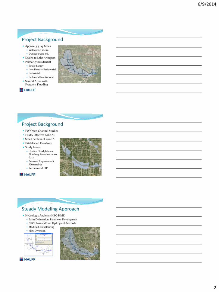
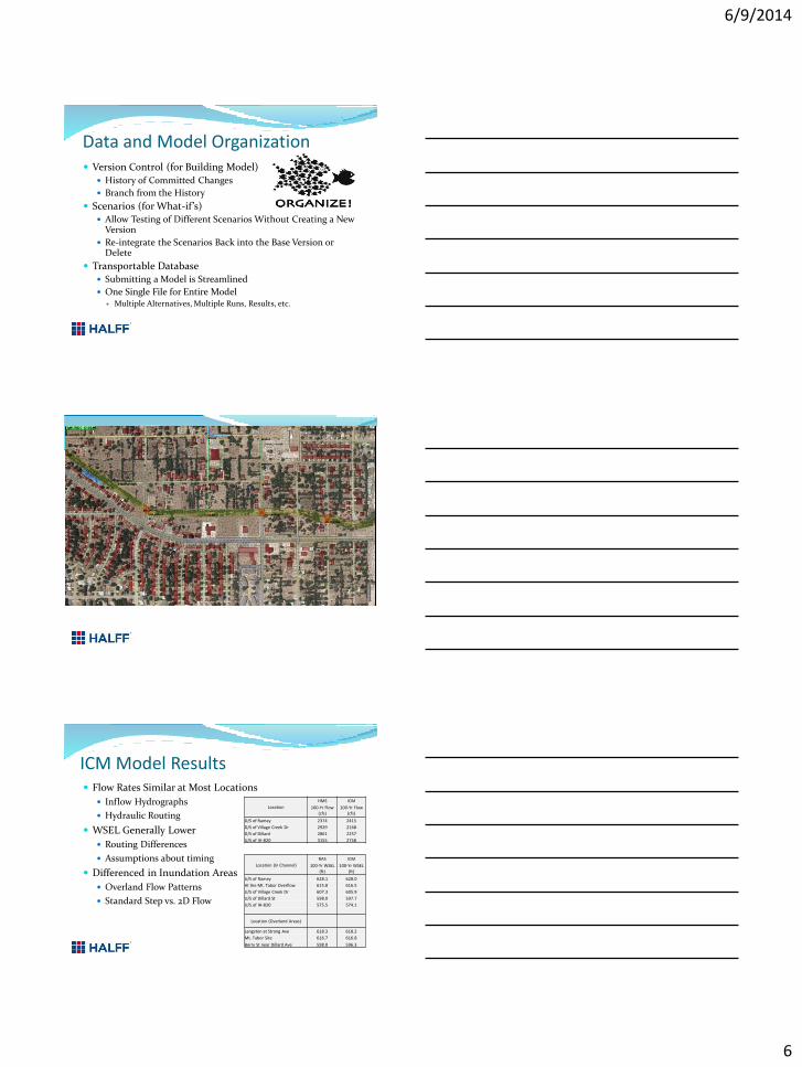
ICM Model Results Flow Rates Similar at Most Locations
Inflow Hydrographs
Hydraulic Routing
WSEL Generally Lower
Routing Differences
Assumptions about timing
Differenced in Inundation Areas
Overland Flow Patterns
Standard Step vs. 2D Flow
Location
HMS ICM
100-Yr Flow (cfs)
100-Yr Flow (cfs)
D/S of Ramey 2374 2415
D/S of Village Creek Dr 2929 2168
D/S of Dillard 2861 2257
U/S of IH-820 3155 2758
Location (In Channel)
RAS ICM
100-Yr WSEL (ft)
100-Yr WSEL (ft)
U/S of Ramey 628.1 628.0
At the Mt. Tabor Overflow 615.8 616.5
U/S of Village Creek Dr 607.3 605.9
U/S of Dillard St 598.0 597.7
U/S of IH-820 575.5 574.1
Location (Overland Areas)
Langston at Strong Ave 618.3 618.2
Mt. Tabor Site 616.7 616.8
Berry St near Dillard Ave 598.0 596.3

6/9/2014
7
ICM Results - Areas of Concern Overflow at Ramey Ave
Overflow at Crenshaw
Lateral Spill at Mt. Tabor
Left Overbank Flow
Flow Along Berry St.
Flow Under IH-820E
HMS/RAS Model Changes Mt. Tabor Diversion set up from channel to the pond
Pond routed and discharged into abandoned channel
New reach along abandoned channel
Lateral weirs along Wildcat to model flow exchange
Lateral weir downstream of Village Creek
Diversion added at Dillard St. accounts for overflow
Diversion added to model storm sewer
Pipes at Burger/Stalcup have limited capacity
Channel XS Cut at LOB (Dillard to Waldorf)
Lateral Weir for overflow at ROB south of Berry St.
Mapping Changes Mapping is based on the
intersection of a water surface TIN or Grid with the terrain.
Top widths must match so not much flexibility
Used shallow flooding to identify floodprone areas outside the “floodplain”

6/9/2014
8
Flood Mitigation Improvement Alternative Evaluation
Channel Improvements
Detention Facilities
Structure Improvements
Improve Future Development?
Mt. Tabor Site
Linear Parks
Model Expansion (SD)
Area Redevelopment
Questions?
Top Related