


Languages
Pages
Legal


UNIVERSITY OF ENGINEERING amp MANAGEMENT JAIPUR Lecture-wise Plan
Subject Name Organizational Behavior Subject Code-HU501 Year 3rd Year Semester Fifth
Module Number Topics Number of Lectures
1
Introduction 23L
1 Organizational Behaviour Definition Importance Historical Background Fundamental Concepts of OB Challenges and Opportunities for OB
2
2 Personality and Attitudes Meaning of personality Personality Determinants and Traits Development of Personality Types of Attitudes Job Satisfaction
3
3 Perception Definition Nature and Importance Factors influencing Perception Perceptual Selectivity Link between Perception and Decision Making
3
4 Motivation Definition Theories of Motivation - Maslowrsquos Hierarchy of Needs Theory McGregorrsquos Theory X amp Y Herzbergrsquos Motivation-Hygiene Theory Alderferrsquos ERG Theory McClellandrsquos Theory of Needs Vroomrsquos Expectancy Theory
5
2
5 Group Behaviour Characteristics of Group Types of Groups Stages of Group Development Group Decision Making
3
6 Communication Communication Process Direction of Communication Barriers to Effective Communication
3
7 Leadership Definition Importance Theories of Leadership Styles
4
Organizational Politics
3
10L
8 Organizational Politics Definition Factors contributing to Political Behaviour
2
9 Conflict Management Traditional vis-a-vis Modern View of Conflict Functional and Dysfunctional Conflict Conflict Process Negotiation ndash Bargaining Strategies Negotiation Process
4
4
10 Organizational Design Various Organizational Structures and their Effects on Human Behaviour Concepts of Organizational Climate and Organizational Culture
4
TOTAL 33L
Faculty In-Charge HOD Humamities Dept
UNIVERSITY OF ENGINEERING amp MANAGEMENT JAIPUR Lecture-wise Plan
Subject Name Foundation Engineering Subject Code CE-501
Year 3rd Year Semester Fifth
Module Number Topics Number of Lectures
1
Earth Pressure Theories 5L
1 Plastic equilibrium of soil Earth pressure at rest Active amp passive earth pressure
1L 2 Rankinersquos earth pressure theories 2L 3 Coulombrsquos earth pressure theories 2L
2
Retaining wall amp sheet pile structures 3L
1 Proportions of retaining walls Design 2L 2 stability checks Gravity and cantilever
retaining wall 1L
3
Stability of Slopes
6L
1 Analysis of finite and infinite slopes 3L
2 Swedish And friction circle method Taylorrsquos stability number Bishoprsquos method of stability analysis
3L
4
Site investigation amp soil exploration 6L
1 Planning of sub-surface exploration methods sampling samples
3L
2 Insitu tests SPT SCPT DCPT Field vane shear Plate load test
3L
5
Shallow foundations 6L 1 Safe bearing capacity Terzaghirsquos bearing
capacity theory 2L
2 Effect of depth of embedment water table 2L 3 Eccentricity of load foundation shape on
bearing capacity 2L
6
Settlement analysis of shallow foundation 4L 1 Immediate and consolidation settlement 1L
2 settlement in various types of soil 2L
3 Allowable bearing capacity 1L
7
Deep foundations 6L
1 Types load transfer mechanism of piles 1L
2 Determination of load carrying capacities of
piles by static and Dynamic formulae 2L
3 Pile group Group efficiency 2L
4 Negative skin friction pile load test 1L
Total Number Of Hours = 36L
Faculty In-Charge HOD CE Dept
Module-1(Earth Pressure Theories)
1 If a retaining wall 5 m high is restrained from yielding what will be the at-rest earth
pressure per meter length of the wall Given the backfill is cohesionless soil having
ϕ= 30deg and γ = 18 kNm3 Also determine the resultant force for the at-rest condition
2 A retaining wall with a vertical back of height 732 m supports a cohesionless soil of
unit weight 173 kNm3 and an angle of shearing resistance ϕ= 30deg The surface of the
soil is horizontal Determine the magnitude and direction of the active thrust per meter
of wall using Rankine theory
3 A wall of 8 m height retains sand having a density of 1936 Mgm3 and an angle of
internal friction of 34deg If the surface of the backfill slopes upwards at 15deg to the
horizontal find the active thrust per unit length of the wall Use Rankines conditio ns
4 A retaining wall has a vertical back and is 732 m high The soil is sandy loam of unit
weight 173 kNm3 It has a cohesion of 12 kNm2 and ϕ= 20deg Neglecting wall
friction determine the active thrust on the wall The upper surface of the fill is
horizontal
5 A rigid retaining wall 1969 ft high has a saturated backfill of soft clay soil The
properties of the clay soil are γsat = 11176 lbft3 and unit cohesion cu = 376 lbft2
Determine (a) the expected depth of the tensile crack in the soil (b) the active earth
pressure before the occurrence of the tensile crack and (c) the active pressure after
the occurrence of the tensile crack Neglect the effect of water that may collect in the
crack
Module-2 (Retaining wall amp sheet pile structures)
1 For the cantilever retaining wall below determine the maximum and minimum
pressure under the base of the cantilever The relevant shear strength parameters of
the backfill and backfill are c=0ϕ=350 unit weight of soil γ=175 kNm3 the unit
weight of the wall material= 235 kNm3 Find also the factor of safety against sliding
overturning considering reduced value of base friction (23ϕ)
2 What are the assumptions made to analysis an anchored sheet pile structure inder free
earth method of analysis Derive the expression of depth of embedment of an
anchored sheet pile structure when driven into cohesive soil Find the embedded depth
of the anchored sheet pile as shown in the fig
UNIVERSITY OF ENGINEERING amp MANAGEMENT JAIPUR Lecture-wise Plan
Subject Name Foundation Engineering Subject Code CE-501
Year 3rd Year Semester Fifth
Module-3 (Stability of Slope)
1 An infinite slope is underlain with an over consolidated clay having c - 210 lbft2 ϕ =
8deg and γsat = 120 lbft3 The slope is inclined at an angle of 10deg to the horizontal
Seepage is parallel to the surface and the ground water coincides with the surface If
the slope fails parallel to the surface along a plane at a depth of 12 ft below the slope
determine the factor of safety
2 A 40deg slope is excavated to a depth of 8 m in a deep layer of saturated clay having
strength parameters c = 60 kNm2 0 = 0 and y= 19 kNm3 Determine the factor of
safety for the trial failure surface shown in Fig
3 An embankment has a slope of 2 (horizontal) to 1 (vertical) with a height of 10 m It
is made of a soil having a cohesion of 30 kNm2 an angle of internal friction of 5deg and
a unit weight of 20 kNm3 Consider any slip circle passing through the toe Use the
friction circle method to find the factor of safety with respect to cohesion
4 The following particulars are given for an earth dam of height 39 ft The slope is
submerged and the slope angle i = 45deg γb = 69 lbft3 c = 550 lbft2 ϕ = 20deg
Determine the factor of safety FS
Module-4 (Site investigation amp soil exploration)
1 Describe various methods of drilling holes for subsurface investigation
2 Describe split spoon sampler What is its use
3 Discuss various types of soil samplers for obtaining undisturbed sample
4 Discuss standard penetration test What are the various corrections
5 Describe static and dynamic cone penetration tests
Module-5 (Shallow foundations)
1 A strip footing of width 3 m is founded at a depth of 2 m below the ground surface in
a (c -ϕ) soil having a cohesion c = 30 kNm2 and angle of shearing resistance ϕ= 35deg
The water table is at a depth of 5 m below ground level The moist weight of soil
above the water table is 1725 kNm3 Determine (a) the ultimate bearing capacity of
the soil (b) the net bearing capacity and (c) the net allowable bearing pressure and
the loadm for a factor of safety of 3 Use the general shear failure theory of Terzaghi
2 A square footing fails by general shear in a cohesionless soil under an ultimate load of
Qult= 16875 kips The footing is placed at a depth of 65 ft below ground level Given
ϕ= 35deg and 7=110 lbft3 determine the size of the footing if the water table is at a
great depth
3 Calculate the net ultimate bearing capacity of a rectangular footing 18 m x 36 m in
plan founded at a depth 16 m below the ground surface The load on the footing acts
an angle of 160 to the vertical and eccentric to the width by 15 cm The unit weight of
the soil is 18 kNm3 Natural water table is at 2m below the ground surface c= 15
kNm2 ϕ=300 Nc=3010 Nq= 1838 and Nγ=224
4 A footing 2m2 is laid at a depth 13 m below the ground surface Determine the net
ultimate bearing capacity using IS code method Given γ=20 kNm3 ϕ=200 c= 0
Nc=3014 Nq= 1838 and Nγ=224 Sc=13 Sq= 12 and Sγ=080
Module-6 (Settlement analysis of shallow foundation)
1 Estimate the immediate settlement of a concrete footing 15 x 15 m in size founded at
a depth of 1 m in silty soil whose modulus of elasticity is 90 kgcm2 The footing is
expected to transmit a unit pressure of 200 kNm2
2 Describe Plate Load test
3 A plate load test using a plate of size 30 x 30 cm was carried out at the level of a
prototype foundation The soil at the site was cohesionless with the water table at
great depth The plate settled by 10 mm at a load intensity of 160 kNm2 Determine
the settlement of a square footing of size 2 x 2 m under the same load intensity
Estimate the load intensity if the permissible settlement of the prototype foundation is
limited to 40 mm
Module-7 (Deep foundations)
1 Describe pile load test
UNIVERSITY OF ENGINEERING amp MANAGEMENT JAIPUR Lecture-wise Plan
Subject Name Foundation Engineering Subject Code CE-501
Year 3rd Year Semester Fifth
2 A concrete pile 30 cm diameter is driven into a medium dense sand (ϕ=350 Nq= 60
DcB=12 γ=21 kNm3 k=1 tanδ=07) for a depth of 8m Estimate the safe load taking
FS 25
3 In a 16 pile group pile diameter is 60 cm and centre to centre spacing of the square
pile group is18m If c=50 kNm2 determine the failure would occur with the pile
acting individually or group Neglect bearing at the tip of the pile All are 15m long
Take the degree of mobilization of shear=07
4 Using Hileyrsquos formula determine the safe pile load With the following data width of
the hammer= 30 kN weight of the pile=18 kN average set under last 6 blows= 125
mm Hammer stroke-= 091mm Hammer efficiency = 70 k1=6 mm k3=25 mm
Pile length 10m and pile diameter 300 mm
UNIVERSITY OF ENGINEERING amp MANAGEMENT JAIPUR Lecture-wise Plan
Subject Name Design of RC Structures Subject Code-CE502
Year 3rd Year Semester Fifth
Module
Number
Topics Number of Lectures
1
Introduction 2L
1 Principles of design of reinforced concrete structures Working stress method
1
2 Principles of design of reinforced concrete structures Limit State Method
1
2
Working stress method of design 2L
1 Basic concepts and IS code provisions (IS 456 2000)for design against bending
moment and shear force
1
1 Basic concepts and IS code provisions (IS 456 2000) for Balanced under-
reinforced and over-reinforced beam slab sections
1
3
Limit state method of design 6L
1 Basic concepts and IS code provisions (IS 456 2000)for design against bending
moment
2
2 Basic concepts and IS code provisions (IS 456 2000) for design against shear
2
3 Basic concepts and IS code provisions
(IS 456 2000) for design of bond stress and development length
2
4
Analysis design and detailing of beam 6L
1 Singly reinforced 2
2 Doubly reinforced 2
5
3 Flanged (T-beam L-beam) 2
Analysis design and detailing of slab 4L
1 One-way slab 2
2 Two-way slab 2
6
Analysis design and detailing of continuous
member
4L
1 Beam 2
2 One- way slab 2
7
Analysis design and detailing of Staircase 2L
1 Dog-legged staircase (waist-type) 1
2 Dog-legged staircase (tread-type) 1
8
Design and detailing of reinforced concrete
short columns
6L
1 Column with axial loading 2
2 Column with uniaxial loading 2
3 Column with biaxial loading 2
9
Shallow foundation 4L
1 Types Design and detailing of reinforced concrete isolated square
2
2 Design and detailing of reinforced concrete isolated rectangular footing for
columns as per IS code provisions
2
Total Number Of Hours = 38
Faculty In-Charge HOD CE Dept Assignment
Module-1(Introduction)
1 Discuss the various design philosophies of design How working stress method is different from limit state method of design
2 Discuss shrinkage and creep of concrete
3 Define characteristic strength of concrete
Module-2 (Working stress method of design)
1 Describe under-reinforced over-reinforced and balanced section 2 Define modulus of rupture cracking moment
3 The cross-section of a singly-reinforced concrete beam is 300 mm wide and 400 mm deep to the centre of the reinforcement which consists of four bars of 16 mm
diameter If the stresses in concrete and steel are not exceed 7 Nmm2 respectively determine the moment of resistance of the section Take m = 1333
Module-3(Limit state method of design)
1 Draw the stress strain block diagram for singly reinforced steel section
2 Find the moment of resistance of a rectangular beam section of width 250 mm and
depth 400 mm reinforced with 3-16ϕ bars Take M20 grade of concrete and Fe250 steel
3 Design shear reinforcement of as simply supported beam 300 mm wide and
600 mm effective depth carrying a UDL of 74 kNm including its own self
weight over an effective span of 6 m The reinforcement consists of 5 bars of 25
mm dia Out of these two bars can be safely bent up at a distance of 1 m from
the support Assume M20 grade of concrete and Fe 415 steel Width of support
= 400 mm
Module-4(Analysis design and detailing of beam)
1 A rectangular reinforced concrete beam located in moderate exposure condition is
simply supported on two walls having an effective span of 6m The beam is carrying
an applied moment of 126 kNm Design the beam section for the applied moment
Check for deflection control only Assume Fe415 steel
2 Find the moment of resistance of doubly reinforced beam of width 300 mm and
effective depth 500 mm having a clear cover of 25mm The beam is reinforced with 3-
UNIVERSITY OF ENGINEERING amp MANAGEMENT JAIPUR Lecture-wise Plan
20ϕ in compression zone and 5-25ϕ in tension zone Assume dʹ=35mm M20 grade of concrete and Fe415 steel
3 Design a doubly reinforced section of width 300 mm and overall depth 600 mm which
has a clear cover of 25mm and an applied moment of 350 kNm Assume M20 grade
of concrete and Fe415 steel 4 Design a doubly reinforced rectangular beam whose size is limited to 250 mm x 400
mm It has to carry a LL of 10 kNm DL of 5 kNm and a conc load DL of 30 kN placed at the midspan The beam is simply supported on two 230 mm thick and 6 m apart masonry wall (centre ndash centre) Assume M25 grade and Fe415 grade of steel
Unit wt of concrete= 25 kNm3 5 Find the moment of resistance of an existing T-beam having the following data
Width of flange bf = 740 mm Width of web bw =240 mm Thickness of flange Df = 100 mm
Effective depth d= 400 mm Area of steel Ast= 5-20 ϕ
Assume M15 grade of concrete and Fe 250 steel
Module-5(Analysis design and detailing of slab)
1 What is one-way and two way slab Explain with the help of suitable diagram 2 Design a simply supported RCC slab for a roof of a hall 35m x 8m (inside
dimension) with 250 mm walls all around Assume a LL of 4 kNm2 and finish 1 kNm2 Use M20 grade of concrete and Fe415 Steel
3 Design a two way slab of size 55mm x 4 mm simply supported on all the four sides
It has to carry a characteristics live load of 8 kNm2 Assume M25 grade of concrete and Fe415 steel Consider mild exposure conditions
Module-6(Analysis design and detailing of continuous member)
1 Design the one-way continuous slab subjected to UDL imposed (fixed) of 5 kNm2
using M20 and Fe415 steel The loas of floor finish is 1 kNm2 The span dimensions
shown in fig are effective spans The width of the beam at support is 300 mm
Module-7(Analysis design and detailing of Staircase)
1 Design a waist slab type dog legged staircase fo an office building given the
following data
Height between floor= 32m
Riser=160mm tread= 270 mm
Width of flight= landing width= 125 m
Live load= 5 kNm2
Finishes load = 06 kNm2
Assume the stairs to be supported on 230 mm thick masonry walls at the outer edges
of the landing parallel to the risers Use M20 concrete and Fe415 steel Assume mild
exposure conditions
Module-8(Design and detailing of reinforced concrete short columns)
1 A concrete column is reinforced with 4-20 ϕ whose size is 450mm x 450mm Determine the ultimate load carrying capacity of the column using M20 grade of concrete and Fe415 steel
2 Design the reinforcement in a column of size 400 mm x 600 mm subjected to an axial load of 2000 kN under service dead load and live load The column has an
unsupported length of 40 m and effectively held in position and restrained against rotation in both ends Use M 25 concrete and Fe 415 steel
3 A corner column (400 mm x 400 mm) located in the lowermost storey of a system of
braced frames is subjected to factored loads Pu = 1300 kN and Mux=190 kNm and Muy= 110 kNm The unsupported length of the column is 35 m Design the
reinforcement in the column assuming M25 concrete and Fe415 steel
Module-9(Shallow foundation)
1 Design an isolated footing for a square column 450 mm x 450 mm reinforced with 8-
25ϕ bars and carrying a service load of 2300 kN The safe soil bearing capacity may
be taken as 300 kNm2 at a depth of 15 m below ground Assume M20 concrete and
Fe 415 steel for the footing and M25 concrete and Fe415 steel for the column
UNIVERSITY OF ENGINEERING amp MANAGEMENT JAIPUR Lecture-wise Plan
Subject Name Concrete Technology Subject Code-CE503 Year 3rd Year Semester Fifth
Module Number Topics Number of Lectures
1
Cement 6L
1 Properties of cement Chemical composition of cement Hydration of cement
1
2 Tests on Cement and Cement Paste ndash Fineness consistency
1
3 Tests on Cement and Cement Paste- Setting time soundness strength
1
4 Quality of Water ndash Mixing Water Curing Water Harmful Contents
1
5 Types of portland cement-Ordinary Rapid hardening lowheat sulphate resisting
1
6 Types of portland cement-Portland slag Portland pozzolana super sulphated cement white cement
1
2
Aggregate 5L
1 Aggregates ndash Classification Mechanical and Physical Properties
1
2 Deleterious Substances Alkali-Aggregate Reaction
1
3 Sieve Analysis Grading Curves Fineness modules Grading Requirements
1
4 Testing of Aggregates ndash Flakiness Elongation Tests Aggregate Crushing Value Ten Percent Fines Value Impact Value Abrasion Value
2
3
Admixtures 5L
1 Definination and Classification Plasticiser Super Plasticiser
1
2 Accelerating admixture Retarding admixture 1
3 Basic concepts and IS code provisions (IS 456 2000) for design of bond stress and development length
1
4 Alkali aggregate expansion inhibitor coloring admixture
1
5 Mineral Admixture 1
4
Fresh Concrete 10L
1 Workability Factors Affecting Workability 1
2 Test for workability- Slump Test Compacting Factor Test Flow Table Test
1
3 Segregation Bleeding Setting Time 1
4 Process of manufacture of concrete- Batching classification
1
5 Process of manufacture of concrete-Mixing Types of drum mixers
1
6 Process of manufacture of concrete-Transporting
1
7 Process of manufacture of concrete- Placing Pumpable concrete
1
8 Process of manufacture of concrete- Compacting Hand compaction vibrator
1
9 Process of manufacture of concrete- Curing 1
10 Process of manufacture of concrete- finishing 1
Strength of concrete 6L
5
1 Factors on which strength of concrete depends Water cement ratio gel space ratio
1
2 Factors on which strength of concrete depends Aggregate cement ratio maximum size of aggregate
1
3 Age and maturity of concrete relationship between compressive strength and flexural strength
1
4 Shrinkage types of shrinkage 1
5 Modulus of elasticity for concrete creep 1
6 Introduction to Non Destructive Tests (Rebound hammer amp Ultrasonic pulse velocity)
1
6 Mix Design 2L
1 Mix Design as per IS 10262 1
2 Light-weight Polymer and Fibre-reinforced concrete
1
Total Number Of Hours = 34
Faculty In-Charge HOD CE Dept
Assignment
Module-1(Cement) 1 Explain initial setting time and final setting time of cement Mention the test used to
determine the same 2 What is hydration of cement What is heat of hydration Write a short note on extra rapid
hardening cement 3 What are the basic constituents of cement Describe the functions of each constituents of
cement 4 Explain Role of Gypsum in cement and role of C 3A in cement 5 What are the chemical compositions of cement 6 Write a short note on Ordinary Portland cement rapid hardening cement extra rapid
hardening cement sulphate resistant cement quick setting cement low heat cement Portland pozzolana cement
7 Define characteristic strength of concrete
Module-2 (Aggregate)
1 Classify aggregate based upon source and size Give example of each
2 Explain of bulking of aggregate
3 What is alkali aggregate reaction
4 Which type of aggregate based on shape forms higher bonds with cement Why
5 Define i) Soundness of aggregate ii) Flakiness index iii) Aggregate crushing value iv) Aggregate impact value v) Elongation Index
6 Which type of aggregate based upon surface texture forms higher bonds with cement Why
7 Explain bulk density and absorption and moisture content of aggregate
Module-3(Admixtures) 1 What is admixture What are the different types of admixture used 2 Explain corrosion inhibitor 3 What are plasticizers Explain the actions involved in plasticizers 4 What is accelerating admixture Explain the two groups of it which is classified based on
performance and application 5 How alkali aggregate expansion inhibiting admixtures prevent this reaction
UNIVERSITY OF ENGINEERING amp MANAGEMENT JAIPUR Lecture-wise Plan
6 Write a short note pozzolans 7 Explain
i) Damp proofing and water proofing admixture ii) Retarding admixture
8 Explain the test for determination of i) Aggregate crushing value ii) Ten percent fines value
Module-4(Fresh Concrete)
1 What is workability of concrete What are the different factors on which workability depends
2 Explain how the workability of concrete depends upon water-cement ratio and size of aggregate
3 What is segregation What are the three types of segregation Write 3 conditions favourable for segregation Write three preventions for segregation
4 Explain the procedure of slump test for workability
5 What is bleeding and laitance
6 Define compaction What are the different types of concrete compaction Explain various types of hand compaction
7 What are the two methods adopted for mixing of concrete Explain
8 Classify different types of drum mixers Explain
9 Explain various types of vibrators used for compaction
10 What is curing of concrete State and explain various methods of curing of concrete
11 What is finishing of concrete What are the different types of finishes Explain any two of them
9 Explain with suitable diagram i) Direct acting Concrete pump ii) Squeeze type concrete pump
Module-5 (Strength of Concrete) 1 Write short note on Maturity of concrete Rebound hammer test on concrete Ultrasonic Pulse
Velocity test on concrete
2 What is shrinkage of concrete State and explain the different types of shrinkage
3 What is the phenomenon of creep of concrete
4 What are the effects of maximum size of aggregate on concrete strength
5 State the various modulus of elasticity of concrete
6 How the strength of concrete get influenced by i) Aggregate cement ratio
ii) Gel-Space ratio
Module-6(Mix Design) 1 Client Requirements
a) Grade designation M40 b) Type of cement OPC 43 grade c) Maximum nominal size of aggregate 20 mm d) Workability 100 mm (slump) e) Exposure condition Severe f) Degree of supervision Good g) Chemical admixture type Super plasticizer h) Method of concrete placing Pumping i) Maximum cement content 450 kgm3 j) Minimum cement content 320 kgm3
k) Maximum WC ratio 045
Test data for materials
a) Cement used OPC 43 grade conforming to IS 8112
b) Specific gravity of cement 315
c) Chemical admixture Super plasticizer conforming to IS 9103
d) Specific gravity of CA amp FA 274 for both
e) Water absorption 05 for CA 10 for FA
f) Free surface moisture of CA amp FA NIL for both
2 Write a short note on light weight concrete polymer concrete
UNIVERSITY OF ENGINEERING amp MANAGEMENT JAIPUR Lecture-wise Plan
Subject Name Engineering Geology Subject Code CE-504
Year 3rd Year Semester Fifth
Module Number Topics Number of Lectures
1
Geology and its importance in Civil Engineering 2L
1 Importance of geology in Engineering 1L
2 Branches of Geology and their importance 1L
2
Mineralogy 3L
1 Definition Physical properties of minerals 2 Study of internal and external structure of
minerals study of crystals 1L
3 Study of various minerals and their use 1L
3
Classification of rocks 4L
1 Igneous rocks Origin mode of occurrence texture classification and engineering importance
1L
2 Sedimentary rocks Process of sedimentation texture classification and engineering importance
2L
3 Metamorphic rocks Agents and types of
metamorphism classification and engineering importance
1L
4
Weathering of rocks 2L
1 Agents and kinds of weathering soil formation amp classification based on
origin
2L
5
Geological work of rivers 1L
1 Origin and stages in the system erosion
transportation and deposition
1L
6
Structural geology
4L
1 Introduction to structural elements of
rocks dip amp strike definition and description
2L
2 Classification of folds faults and joints importance of geological structures in Civil Engineering
2L
7
Earthquakes and seismic hazards
4L
1 Definition Causes and effects of earthquake Focus and epicentre of earthquake
1L
2 Types of earthquake seismic waves and seismographs
2L
3 Magnitude amp Intensity Of Earthquake Mercellis Intensity Scale and Richters Scale of magnitude
1L
8
Engineering properties of rocks
2L
1 Porosity permeability compressive strength tensile strength and abrasive resistance
2L
9
Rocks as construction materials 3L
1 Qualities required for building and ornamental stones foundations concrete aggregate railway ballast road metal pavement flooring and roofing
3L
10
Geophysical exploration 4L
1 Methods of Geophysical Exploration 1L
2 Methods of Geophysical explorations-
Electrical resistivity method field procedure-resistivity profiling electrode
configuration
2L
3 Geophysical surveys in ground water and other Civil Engg Projects
1L
11
Applied Geology 4L
1 Surface and subsurface geological and
geophysical investigations in major Civil Engg Projects
2L
2 Geological studies of Dams and
reservoir sites
1L
3 Geological studies for selection of
tunnels and underground excavations
1L
12 Landslides 3L
1 Types of landslides causes effects and prevention of landslides
3L
Total Number Of Hours = 36L
Faculty In-Charge HOD CE Dept
Assignments
Unit 1
1 What do you mean by Geology
2 Define the different branches of geology
3 Elaborate the importance of geology with respect to Civil Engineering
Unit 2
1 What is cleavage Draw a neat sketch and give an example of cleavage
2 What is fracture Draw a neat sketch and give an example
3 Define lsquoCrystalrsquo amp lsquoMineralrsquo How would you systematically describe amp
identify minerals in hand specimen Cite common examples
Unit 3
1 What do you mean by metamorphic rock What are the types of
metamorphic rock Explain the use of metamorphic rock in civil
engineering projects
2 What do you mean by igneous rock What are the types of igneous rock
Explain the use of igneous rock in civil engineering projects
3 What do you mean by sedimentary rock What are the types of
sedimentary rock Explain the use of sedimentary rock in civil
engineering projects
4 Write the properties of
i) Igneous Rock
ii) Sedimentary Rock
iii) Metamorphic Rock
Unit 4
1 Explain how climate rock types topography and time influence the
types of soil produced by weathering
2 What do you mean by weathering What are the different types of
weathering Describe all of them in brief
3 How are soils formed How are they classified on the basis of formation
and origin
Unit 5
1 Describe the stages of the river
2 Write briefly on geological work of rivers
Unit 6
1 Write a note on internal constitution of the earth
2 Define fault of a structure and also give a comprehensive classification of
fault
3 Define fold and discuss different parts of a folded layer Write a note on
engineering consideration of fold structures in rock
4 Give the schematic diagrams of symmetrical asymmetrical overturned
and recumbent anticlines and synclines
5 What is unconformity What are the different types of unconformities
6 Distinguish between joint and fault
Unit 7
1 What do you mean by focus and epicentre of earthquake
2 Describe the causes and effects of Earthquake
3 What do you mean by seismic waves Explain the different types of
seismic waves
4 Write Short note on the following
i) Richter Magnitude Scale
ii) Mercalli Intensity Scale
5 Give an account of important factors to be considered for evolving
seismic designs in a seismic region
6 What are the parameters of an earthquake What do you mean by the
term intensity and magnitude of an earthquake Explain the terms in the
formula for magnitude of an earthquake Describe a method of
determining earthquake epicentre
7 Write briefly on the nature of precautions required in major constructions
in earthquake-prone regions
8 How are earthquake waves useful in deciphering the interior of the earth
Unit 8
1 Define the following term
i) Porosity
ii) Permeability
iii) Compressive Strength
iv) Tensile Strength
v) Abrasive resistance
Unit 9
1 Explain various properties that need thorough investigation for selection
of stones for use in building construction
2 Mention the criteria for selection of railway ballast
Unit 10
1 Explain the necessity and importance of Geophysical investigations in
Civil Engineering Project
2 In general how many kinds of Geophysical methods of investigation are
carried out for the physical property of subsurface formations for Civil
Engineering Project
3 Write the name of the Geophysical methods which is carried out for
measuring the following physical properties
4 Write the Geophysical Unit of these physical properties
Density Magnetic Susceptibility Natural Remanent Magnetism
Electrical Resistivity Electrical Conductivity Electrochemical Activity
Elastic Property
5 Describe the general importance of the following geological investigation
for any large Civil Engineering Project
Topography Lithology Structure Groundwater conditions and
Seismicity of the area
6 What are the different zones of groundwater What is cone of depression
in groundwater How is this property of groundwater useful in civil
engineering construction in an area that lies below the ground water
table Illustrate with neat sketches
Unit 11
1 Write briefly on the principle of electrical receptivity method in
geophysical investigation Comment an interpretation on receptivity data
2 Write briefly on geological studies for selection of tunnel sites
3 How structural geological and engineering properties of rock influence
the selection of dam sites
4 What is a reservoir What are the geological factors that are consider for
selection of sites for construction of reservoir
Unit 12
1 What are the Causes and effects of landslide
2 What do you mean by landslide Describe the different types of
landslide
3 What are the preventive measures that can be taken to prevent
landslides
UNIVERSITY OF ENGINEERING amp MANAGEMENT JAIPUR Lab Manual
Civil Engineering Department
Title of Course Soil Mechanics Lab-II
Course Code CE 591
L-T-P scheme 0-0-3 Course Credit 2
Objectives 1 The students will be able to differentiate between different types of soils and characteristics of each type of soil 2 The students will be involved in the collection of the field samples and identification of the types of soils without natural testing 3 The students will be able to determine the natural moisture content of the soil 4 The students will be able to determine the compressibility characteristics of the soil by Oedometer test which involves the co-efficient of consolidation and compression index
Learning Outcomes The students will develop a clear understanding of the different types of soils and will be able to identify the types of soils as per the Indian Standards The students will be able to determine the moisture contents and specific gravity of cohesive soils and cohesion less soils The students will also develop a clear understanding of the compaction characteristics of the soil The students will develop a understanding of the Triaxial Test that is to determine the shear parameters of the soil They will also develop the basic concepts of Direct Shear Test and to find out the compressive strength of the soil The students will be exposed to the concepts of Standard Penetration Test which involves the collection of field samples and performing tests for the determination of various soil parameters like bearing capacity compressive strength
Course Contents
Practicals that must be done in this course are listed below
Determination of compressibility characteristics of soil by Oedometer test ( co-efficient of consolidation amp compression Index)
Determination of unconfined compressive strength of soil Determination of Shear parameter of soil by Direct shear test Determination of undrained shear strength of soil by Vane shear test Determination of shear parameter of soil by Triaxial test (UU) Standard Penetration Test Expt No 6 by large groups in the field
Text Book 1 Soil testing by TW Lamb (John Willey) 2 SP-36 (Part-I amp Part ndashII) 3 Soil Mechanics Laboratory Manual by B M Das OXFORD UNIVERSITY PRESS 4 Measurement of engineering properties of soil by EJaibaba Reddy amp K Ramasastri
EXPERIMENT NO 1 DIRECT SHEAR TEST
Objective
To determine the shearing strength of the soil using the direct shear apparatus
NEED AND SCOPE
In many engineering problems such as design of foundation retaining walls slab bridges
pipes sheet piling the value of the angle of internal friction and cohesion of the soil involved
are required for the design Direct shear test is used to predict these parameters quickly The
laboratory report cover the laboratory procedures for determining these values for
cohesionless soils
PLANNING AND ORGANIZATION
Apparatus
1 Direct shear box apparatus
2 Loading frame (motor attached)
3 Dial gauge
4 Proving ring
5 Tamper
6 Straight edge
7 Balance to weigh upto 200 mg
8 Aluminum container
9 Spatula
KNOWLEDGE OF EQUIPMENT
Strain controlled direct shear machine consists of shear box soil container loading unit
proving ring dial gauge to measure shear deformation and volume changes A two piece
square shear box is one type of soil container used
A proving ring is used to indicate the shear load taken by the soil initiated in the shearing
plane
PROCEDURE
1 Check the inner dimension of the soil container
2 Put the parts of the soil container together
3 Calculate the volume of the container Weigh the container
4 Place the soil in smooth layers (approximately 10 mm thick) If a dense sample is desired
tamp the soil
5 Weigh the soil container the difference of these two is the weight of the soil Calculate the
density of the soil
6 Make the surface of the soil plane
7 Put the upper grating on stone and loading block on top of soil
8 Measure the thickness of soil specimen
UNIVERSITY OF ENGINEERING amp MANAGEMENT JAIPUR Lab Manual
Civil Engineering Department
9 Apply the desired normal load
10Remove the shear pin
11 Attach the dial gauge which measures the change of volume
12 Record the initial reading of the dial gauge and calibration values
13 Before proceeding to test check all adjustments to see that there is no connection between
two parts except sandsoil
14 Start the motor Take the reading of the shear force and record the reading
15Take volume change readings till failure
16 Add 5 kg normal stress 05 kgcm2 and continue the experiment till failure
17 Record carefully all the readings Set the dial gauges zero before starting the experiment
GENERAL REMARKS
1 In the shear box test the specimen is not failing along its weakest plane but along a
predetermined or induced failure plane ie horizontal plane separating the two halves of the
shear box This is the main draw back of this test Moreover during loading the state of
stress cannot be evaluated It can be evaluated only at failure condition ie Mohr1051878s circle can
be drawn at the failure condition only Also failure is progressive
2 Direct shear test is simple and faster to operate As thinner specimens are used in shear
box they facilitate drainage of pore water from a saturated sample in less time This test is
also useful to study friction between two materials 1051878 one material in lower half of box and
another material in the upper half of box
3 The angle of shearing resistance of sands depends on state of compaction coarseness of
grains particle shape and roughness of grain surface and grading It varies between
28o(uniformly graded sands with round grains in very loose state) to 46o(well graded sand
with angular grains in dense state)
4 The volume change in sandy soil is a complex phenomenon depending on gradation
particle shape state and type of packing orientation of principal planes principal stress ratio
stress history magnitude of minor principal stress type of apparatus test procedure method
of preparing specimen etc In general loose sands expand and dense sands contract in volume
on shearing There is a void ratio at which either expansion contraction in volume takes
place This void ratio is called critical void ratio Expansion or contraction can be inferred
from the movement of vertical dial gauge during shearing
5 The friction between sand particle is due to sliding and rolling friction and interlocking
action
The ultimate values of shear parameter for both loose sand and dense sand approximately
attain the same value so if angle of friction value is calculated at ultimate stage slight
disturbance in density during sampling and preparation of test specimens will not have much
effect
EXPERIMENT NO 2 CONSOLIDATION TEST
OBJECTIVE
To determine the settlements due to primary consolidation of soil by conducting one
dimensional test
NEED AND SCOPE
The test is conducted to determine the settlement due to primary consolidation To determine
i Rate of consolidation under normal load
ii Degree of consolidation at any time
iii Pressure-void ratio relationship
iv Coefficient of consolidation at various pressures
v Compression index
From the above information it will be possible for us to predict the time rate and extent of
settlement of structures founded on fine-grained soils It is also helpful in analyzing the stress
history of soil Since the settlement analysis of the foundation depends mainly on the values
determined by the test this test is very important for foundation design
PLANNING AND ORGANIZATION
1 Consolidometer consisting essentially
a) A ring of diameter = 60mm and height = 20mm
b) Two porous plates or stones of silicon carbide aluminum oxide or porous metal
c) Guide ring
d) Outer ring
e) Water jacket with base
f) Pressure pad
g) Rubber basket
2 Loading device consisting of frame lever system loading yoke dial gauge fixing device
and weights
UNIVERSITY OF ENGINEERING amp MANAGEMENT JAIPUR Lab Manual
Civil Engineering Department
3 Dial gauge to read to an accuracy of 0002mm
4 Thermostatically controlled oven
5 Stopwatch to read seconds
6 Sample extractor
7 Miscellaneous items like balance soil trimming tools spatula filter papers sample
containers
PRINCIPAL INVOLVED
When a compressive load is applied to soil mass a decrease in its volume takes place the
decease in volume of soil mass under stress is known as compression and the property of soil
mass pertaining to its tendency to decrease in volume under pressure is known as
compressibility In a saturated soil mass having its void filled with incompressible water
decrease in volume or compression can take place when water is expelled out of the voids
Such a compression resulting from a long time static load and the consequent escape of pore
water is termed as consolidation
Then the load is applied on the saturated soil mass the entire load is carried by pore water in
the beginning As the water starts escaping from the voids the hydrostatic pressure in water
gets gradually dissipated and the load is shifted to the soil solids which increases effective on
them as a result the soil mass decrease in volume The rate of escape of water depends on the
permeability of the soil
1) From the sample tube eject the sample into the consolidation ring The sample should
project about one cm from outer ring Trim the sample smooth and flush with top and bottom
of the ring by using a knife Clean the ring from outside and keep it ready from weighing
2) Remoulded sample
a) Choose the density and water content at which samples has to be compacted from the
moisture density relationship
b) Calculate the quantity of soil and water required to mix and compact
c) Compact the specimen in compaction mould in three layers using the standard rammers
d) Eject the specimen from the mould using the sample extractor
PROCEDURE
1 Saturate two porous stones either by boiling in distilled water about 15 minute or by
keeping them submerged in the distilled water for 4 to 8 hrs Wipe away excess water
Fittings of the consolidometer which is to be enclosed shall be moistened
2 Assemble the consolidometer with the soil specimen and porous stones at top and bottom
of specimen providing a filter paper between the soil specimen and porous stone Position
the pressure pad centrally on the top porous stone
3 Mount the mould assembly on the loading frame and center it such that the load applied is
axial
4 Position the dial gauge to measure the vertical compression of the specimen The dial
gauge holder should be set so that the dial gauge is in the begging of its releases run allowing
sufficient margin for the swelling of the soil if any
5 Connect the mould assembly to the water reservoir and the sample is allowed to saturate
The level of the water in the reservoir should be at about the same level as the soil specimen
6 Apply an initial load to the assembly The magnitude of this load should be chosen by trial
such that there is no swelling It should be not less than 50 gcm3 for ordinary soils amp 25
gcm2 for very soft soils The load should be allowed to stand until there is no change in dial
gauge readings for two consecutive hours or for a maximum of 24 hours
7 Note the final dial reading under the initial load Apply first load of intensity 01 kgcm2
start the stop watch simultaneously Record the dial gauge readings at various time intervals
The dial gauge readings are taken until 90 consolidation is reached Primary consolidation
is gradually reached within 24 hrs
8 At the end of the period specified above take the dial reading and time reading Double the
load intensity and take the dial readings at various time intervals Repeat this procedure fir
successive load increments The usual loading intensity are as follows
a 01 02 05 1 2 4 and 8 kgcm2
9 After the last loading is completed reduce the load to 60 of the value of the last load and
allow it to stand for 24 hrs Reduce the load further in steps of the previous intensity till an
intensity of 01 kgcm2 is reached Take the final reading of the dial gauge
10 Reduce the load to the initial load keep it for 24 hrs and note the final readings of the dial
gauge
11 Quickly dismantle the specimen assembly and remove the excess water on the soil
specimen in oven note the dry weight of it
In the log fitting method a plot is made between dial reading and logarithmic of time the
time corresponding to 50 consolidation is determined
In the square root fitting method a plot is made between dial readings and square root of time
and the time corresponding to 90 consolidation is determined The values of Cv are
recorded in table
EXPERIMENT NO 3 UNCONFINED COMPRESSION TEST
OBJECTIVE determine shear parameters of cohesive soil
UNIVERSITY OF ENGINEERING amp MANAGEMENT JAIPUR Lab Manual
Civil Engineering Department
NEED AND SCOPE OF THE EXPERIMENT
It is not always possible to conduct the bearing capacity test in the field Some times it is
cheaper to take the undisturbed soil sample and test its strength in the laboratory Also to
choose the best material for the embankment one has to conduct strength tests on the samples
selected Under these conditions it is easy to perform the unconfined compression test on
undisturbed and remoulded soil sample Now we will investigate experimentally the strength
of a given soil sample
PLANNING AND ORGANIZATION
We have to find out the diameter and length of the specimen
EQUIPMENT
1 Loading frame of capacity of 2 t with constant rate of movement What is the least count
of the dial gauge attached to the proving ring
2 Proving ring of 001 kg sensitivity for soft soils 005 kg for stiff soils
3 Soil trimmer
4 Frictionless end plates of 75 mm diameter (Perspex plate with silicon grease coating)
5 Evaporating dish (Aluminum container)
6 Soil sample of 75 mm length
7 Dial gauge (001 mm accuracy)
8 Balance of capacity 200 g and sensitivity to weigh 001 g
9 Oven thermostatically controlled with interior of non-corroding material to maintain the
temperature at the desired level What is the range of the temperature used for drying the soil
10 Sample extractor and split sampler
11 Dial gauge (sensitivity 001mm)
12 Verniercalipers
EXPERIMENTAL PROCEDURE (SPECIMEN)
1 In this test a cylinder of soil without lateral support is tested to failure in simple
compression at a constant rate of strain The compressive load per unit area required to fail
the specimen as called Unconfined compressive strength of the soil
Preparation of specimen for testing
A Undisturbed specimen
1 Note down the sample number bore hole number and the depth at which the sample was
taken
2 Remove the protective cover (paraffin wax) from the sampling tube
3 Place the sampling tube extractor and push the plunger till a small length of sample moves
out
4 Trim the projected sample using a wire saw
5 Again push the plunger of the extractor till a 75 mm long sample comes out
6 Cutout this sample carefully and hold it on the split sampler so that it does not fall
7 Take about 10 to 15 g of soil from the tube for water content determination
8 Note the container number and take the net weight of the sample and the container
9 Measure the diameter at the top middle and the bottom of the sample and find the average
and record the same
10 Measure the length of the sample and record
11 Find the weight of the sample and record
B Moulded sample
1 For the desired water content and the dry density calculate the weight of the dry soil Ws
required for preparing a specimen of 38 cm diameter and 75 cm long
2 Add required quantity of water Ww to this soil
Ww = WS W100 gm
3 Mix the soil thoroughly with water
4 Place the wet soil in a tight thick polythene bag in a humidity chamber and place the soil in
a constant volume mould having an internal height of 75 cm and internal diameter of 38
cm
5 After 24 hours take the soil from the humidity chamber and place the soil in a constant
volume mould having an internal height of 75 cm and internal diameter of 38 cm
6 Place the lubricated moulded with plungers in position in the load frame
7 Apply the compressive load till the specimen is compacted to a height of 75 cm
8 Eject the specimen from the constant volume mould
9 Record the correct height weight and diameter of the specimen
Test procedure
1 Take two frictionless bearing plates of 75 mm diameter
UNIVERSITY OF ENGINEERING amp MANAGEMENT JAIPUR Lab Manual
Civil Engineering Department
2 Place the specimen on the base plate of the load frame (sandwiched between the end
plates)
3 Place a hardened steel ball on the bearing plate
4 Adjust the center line of the specimen such that the proving ring and the steel ball are in
the same line
5 Fix a dial gauge to measure the vertical compression of the specimen
6 Adjust the gear position on the load frame to give suitable vertical displacement
7 Start applying the load and record the readings of the proving ring dial and compression
dial for every 5 mm compression
8 Continue loading till failure is complete
9 Draw the sketch of the failure pattern in the specimen
UNIVERSITY OF ENGINEERING amp MANAGEMENT JAIPUR Lab Manual
Civil Engineering Department
Title of Course Concrete Lab
Course Code CE 592
L-T-P scheme 0-0-3 Course Credit 2
Objectives 1 The students will develop a clear understanding of the various tests conducted on concrete in both fresh and hardened states 2 They will develop the concepts of workability slump test Vee-bee compacting test and compaction factor tests which are conducted on fresh concrete to determine the fresh concrete properties 3 The students will be able to perform mix design of concrete and as per the proportion develop concrete mixes of different compressive strengths 4 The students will be able to perform and analyze the various properties of concrete in hardened state like compressive strength Split Tensile Strength Flexure Tests 5 The students will be exposed to non-destructive testing like Rebound Hammer and Ultrasonic Pulse Velocity test Learning Outcomes The students will be able to understand the various tests which are performed on cement like specific gravity normal consistency setting time The students will also develop a clear understanding of the compressive strength on cement mortar cubes The students will also develop a clear understanding of the various tests on fine aggregates like sieve analysis fineness modulus moisture content bulk density The students will also develop concepts on various tests conducted on coarse aggregate like fineness modulus bulk density
Course Contents
Practicals that must be done in this course are listed below
1 Tests on cement ndash specific gravity fineness soundness normal consistency setting time compressive strength on cement mortar cubes 2 Tests on fine aggregate ndash specific gravity bulking sieve analysis fineness modules moisture content bulk density and deleterious materials 3 Tests on coarse aggregate - specific gravity sieve analysis fineness modulus bulk density 4 Tests on Fresh Concrete Workability Slump Vee-Bee Compaction factor tests 5 Hardened Concrete Compressive strength on Cubes Split tensile strength Static modulus of elasticity Flexure tests Non destructive testing (Rebound hammer amp Ultrasonic pulse velocity) 6 Mix Design of Concrete
Text Book 1 Relevant latest IS codes on Aggregates Cement amp Concrete [269 383 2386 10262(2009) SP23] 2 Laboratory manual of concrete testing by VV Sastry and M L Gambhir
Experiment No 1
Objective To determine the normal consistency of a given sample of cement
Apparatus Vicat apparatus conforming to IS 5513-1976 Balance Gauging Trowel Stop
Watch etc
Theory For finding out initial setting time final setting time and soundness of cement and
strength a parameter known as standard consistency has to be used The standard consistency
of a cement paste is defined as that consistency which will permit a Vicat plunger having 10
mm diameter and 50 mm length to penetrate to a depth of 33-35 mm from the top of the
mould
Procedure
1 The standard consistency of a cement paste is defined as that consistency which will permit
the Vicat plunger to penetrate to a point 5 to 7 mm from the bottom of the Vicat mould
2 Initially a cement sample of about 300 g is taken in a tray and is mixed with a known
percentage of water by weight of cement say starting from 26 and then it is increased by
every 2 until the normal consistency is achieved
3 Prepare a paste of 300 g of Cement with a weighed quantity of potable or distilled water
taking care that the time of gauging is not less than 3 minutes nor more than 5 min and the
gauging shall be completed before any sign of setting occurs The gauging time shall be
counted from the time of adding water to the dry cement until commencing to fill the mould
4 Fill the Vicat mould (E) with this paste the mould resting upon a non-porous plate After
completely filling the mould smoothen the surface of the paste making it level with the top
of the mould The mould may be slightly shaken to expel the air
5 Place the test block in the mould together with the non-porous resting plate under the rod
bearing the plunger lower the plunger gently to touch the surface of the test block and
quickly release allowing it to sink into the paste This operation shall be carried out
immediately after filling the mould
6 Prepare trial pastes with varying percentages of water and test as described above until the
amount of water necessary for making up the standard consistency as defined in Step 1 is
found
Experiment No 2
Objective To determine the initial and final setting time of a given sample of cement
Apparatus Vicat apparatus conforming to IS 5513-1976 Balance Gauging Trowel Stop
Watch etc
Theory For convenience initial setting time is regarded as the time elapsed between the
moments that the water isadded to the cement to the time that the paste starts losing its
plasticity The final setting time is the timeelapsed between the moment the water is added to
the cement and the time when the paste has completely lost its plasticity and has attained
sufficient firmness to resist certain definite pressure
Procedure
1 Preparation of Test Block - Prepare a neat 300 gms cement paste by gauging the cement
with 085 times the water required to give a paste of standard consistency Potable or distilled
water shall be used in preparing the paste
2 Start a stop-watch at the instant when water is added to the cement Fill the Vicat mould
with a cement paste gauged as above the mould resting on a nonporous plate Fill the mould
completely and smooth off the surface of the paste making it level with the top of the mould
UNIVERSITY OF ENGINEERING amp MANAGEMENT JAIPUR Lab Manual
Civil Engineering Department
3 Immediately after moulding place the test block in the moist closet or moist room and
allow it to remain there except when determinations of time of setting are being made
4 Determination of Initial Setting Time - Place the test block confined in the mould and
resting on the non-porous plate under the rod bearing the needle ( C ) lower the needle
gently until it comes in contact with the surface of the test block and quickly release
allowing it to penetrate into the test block
5 Repeat this procedure until the needle when brought in contact with the test block and
released as described above fails to pierce the block beyond 50 plusmn 05 mm measured from the
bottom of the mould shall be the initial setting time
6 Determination of Final Setting Time - Replace the needle (C) of the Vicat apparatus by the
needle with an annular attachment (F)
7 The cement shall be considered as finally set when upon applying the needle gently
to the surface of the test block the needle makes an impression thereon while the attachment
fails to do so
8 The period elapsing between the time when water is added to the cement and the time at
which the needle makes an impression on the surface of test block while the attachment fails
to do so shall be the final setting time
Experiment No 3
Objective To determine the compressive strength sample of cement
Apparatus The standard sand to be used in the test shall conform to IS 650-1966 Vibration
Machine Poking Rod Cube Mould of 706 mm size conforming to IS 10080-1982
Balance Gauging Trowel Stop Watch Graduated Glass Cylinders etc
Theory The compressive strength of hardened cement is the most important of all the
properties Therefore it is not surprising that the cement is always tested for its strength at the
laboratory before the cement is used in important works Strength tests are not made on neat
cement paste because of difficulties of excessive shrinkage and subsequent cracking of neat
cement
Procedure
1 Preparation of test specimens - Clean appliances shall be used for mixing and the
temperature of water and that of the test room at the time when the above operations are
being performed shall be 27 plusmn 2degC Potabledistilled water shall be used in preparing the
cubes
2 The material for each cube shall be mixed separately and the quantity of cement standard
sand and water shall be as follows
Cement 200 g and Standard Sand 600 g
Water per cent of combined mass of cement and sand where P is the percentage of water
required to produce a paste of standard consistency determined as described in IS 4031 (Part
4)-1988 or Experiment 1
3 Place on a nonporous plate a mixture of cement and standard sand Mix it dry with a
trowel for one minute and then with water until the mixture is of uniform colour The
quantity of water to be used shall be as specified in step 2 The time of mixing shall in any
event be not less than 3 min and should the time taken to obtain a uniform colour exceed 4
min the mixture shall be rejected and the operation repeated with a fresh quantity of cement
sand and water
4 Place the assembled mould on the table of the vibration machine and hold it firmly in
position by means of a suitable clamp
6 Immediately after mixing the mortar in accordance with step 1 amp 2 place the mortar in the
cube mould and prod with the rod Place the mortar in the hopper of the cube mould and prod
again as specified for the first layer and then compact the mortar by vibration
7 The period of vibration shall be two minutes at the specified speed of 12 000 plusmn 400
vibration per minute
8 Curing Specimens - keep the filled moulds in moist closet or moist room for 24 plusmn 1 hour
after completion of vibration At the end of that period remove them from the moulds and
immediately submerge in clean fresh water and keep there until taken out just prior to
breaking and shall be maintained at a temperature of 27 plusmn 2degC
9 Test three cubes for compressive strength for each period of curing mentioned under the
relevant specifications (ie 3 days 7 days 28 days)
10 The cubes shall be tested on their sides without any packing between the cube and the
steel plattens of the testing machine One of the plattens shall be carried on a base and shall
be self-adjusting and the load shall be steadily and uniformly applied starting from zero at a
rate of 40Nmm2min
Experiment No4
Objective To determine specific gravity of a given sample of fine aggregate
Apparatus Pycnometer A 1 000-ml measuring cylinder well-ventilated oven Taping rod
Filter papers and funnel etc
Theory
Procedure 1 Sample of about 500 g shall be placed in the tray and covered with distilled
water at a temperature of 22 to 32degC The sample shall remain immersed for 24 plusmn l2 hours
2 The water shall then be carefully drained from the sample The saturated and surface-dry
sample shall be weighed (weight A)
UNIVERSITY OF ENGINEERING amp MANAGEMENT JAIPUR Lab Manual
Civil Engineering Department
3 The aggregate shall then be placed in the pycnometer which shall be filled with distilled
water Any trapped air shall be eliminated by rotating the pycnometer on its side the hole in
the apex of the cone being covered with a finger The pycnometer shall be dried on the
outside and weighed (weight B)
4 The contents of the pycnometer shall be emptied into the tray Thepycnometer shall be
refilled with distilled water to the same level as 21 before dried on the outside and weighed
(weight C)
5 The water shall then be carefully drained from the sample The sample shall be placed in
the oven in the tray at a temperature of 100 to 110degC for 24 f l2 hoursIt shall be cooled in the
air-tight container and weighed (weight D)
Experiment No5
Objective To determine fineness modulus of fine aggregate and classifications based on IS
383-1970
Apparatus Test Sieves conforming to IS 460-1962 Specification of 475 mm 236 mm
118 mm 600 micron 300micron 150 micron Balance Gauging Trowel Stop Watch etc
Theory The sieve analysis is conducted to determine the particle size distribution in a sample
of aggregate which is known as gradation The following limits used to classifie
Procedure
1 The sample shall be brought to an air-dry condition before weighing and sieving The air-
dry sample shall be weighed and sieved successively on the appropriate sieves starting with
the largest
2 Material shall not be forced through the sieve by hand pressure Lumps of fine material if
present may be broken by gentle pressure with fingers against the side of the sieve
3 Light brushing with a fine camel hair brush may be used on the 150-micron and 75-micron
IS Sieves to prevent aggregation of powder and blinding of apertures
4 On completion of sieving the material retained on each sieve together with any material
cleaned from the mesh shall be weighed
Experiment No 6
Objective To determination of particle size distribution of coarse aggregates by sieving
Apparatus Test Sieves conforming to IS 460-1962 Specification of 80 mm 40 mm20 mm
10 mm 475 mm Balance Gauging Trowel Stop Watch etc
Theory Grading refers to the determination of the particle-size distribution for aggregate
Grading limits and maximum aggregate size are specified because grading and size affect the
amount of aggregate used as well as cement and water requirements workability
pumpability and durability of concrete In general if the water-cement ratio is chosen
correctly a wide range in grading can be used without a major effect on strength When gap-
graded aggregate are specified certain particle sizes of aggregate are omitted from the size
continuum Gap-graded aggregate are used to obtain uniform textures in exposed aggregate
concrete
Procedure
1 The sample shall be brought to an air-dry condition before weighing and sieving This may
be achieved either by drying at room temperature or by heating at a temperature of 100 to
110degC The air-dry sample shall be weighed and sieved successively on the appropriate
sieves starting with the largest
2 Material shall not be forced through the sieve by hand pressure
3 On completion of sieving the material retained on each sieve together with any material
cleaned from the mesh shall be weighed
Experiment No 7
Objective To determine crushing value of course aggregate
Apparatus A 15-cm diameter open-ended steel cylinder with plunger and base-plate of the
general form and dimensions shown in Fig A straight metal tamping rod A balance of
capacity 3 kg readable and accurate to one gram IS Sieves of sizes 125 10 and 236 mm
For measuring the sample cylindrical metal measure of sufficient rigidity to retain its form
under rough usage and of the following internal dimensions Diameter 115 cm and Height
180 cm
Theory The aggregate crushing valuelsquo gives a relative measure of the resistance of an
aggregate to crushing under a gradually applied compressive load With aggregate of
aggregate crushing valuelsquo 30 or higher the result may be anomalous and in such cases
theten percent fines valuelsquo should be determined instead
Procedure
1 The material for the standard test shall consist of aggregate passing a 125 mm IS Sieve
and retained on a 10 mm IS Sieve and shall be thoroughly separated on these sieves before
testing
2 The aggregate shall be tested in a surface-dry condition If dried by heating the period of
drying shall not exceed four hours the temperature shall be 100 to 110degC and th aggregate
shall be cooled to room temperature before testing
3 The appropriate quantity may be found conveniently by filling the cylindrical measure in
three layers of approximately equal depth each layer being tamped 25 times with the rounded
end of the tamping rod and finally leveled off using the tamping rod as a straight-edge
4 The weight of material comprising the test sample shall be determined (Weight A) and the
same weight of sample shall be taken for the repeat test
UNIVERSITY OF ENGINEERING amp MANAGEMENT JAIPUR Lab Manual
Civil Engineering Department
5 The apparatus with the test sample and plunger in position shall then be placed between
the platens of the testing machine and loaded at as uniform a rate as possible so that the total
load is reached in 10 minutes The total load shall be 400 kN
6 The load shall be released and the whole of the material removed from the cylinder and
sieved on a 236 mm IS Sieve for the standard test The fraction passing the sieve shall be
weighed (Weight B)
The aggregate crushing value should not be more than 45 per cent for aggregate used for
concrete other than wearing surfaces and 30 per cent for concrete used for wearing surfaces
such a runways roads and air pavements
Experiment No 8
Objective To determine the impact value of course aggregate
Apparatus An impact testing machine of the general form shown in Fig 2 and complying
with the following
1 A cylindrical steel cup of internal dimensions Diameter 102 mm Depth 50 mm and not
less than 63 mm thick
2 A metal hammer weighing 135 to 140 kg the lower end of which shall be cylindrical in
shape 1000 mm in diameter and 5 cm long with a 2 mm chamfer at the lower edge and
case-hardened The hammer shall slide freely between vertical guides so arranged that the
lower (cylindrical) part of the hammer is above and concentric with the cup
3 Means for raising the hammer and allowing it to fall freely between the vertical guides
from a height of 3800 mm on to the test sample in the cup and means for adjusting the
height of fall within 5 mm
Sieves-The IS Sieves of sizes 125 10 and 236 mm Tamping Rod balance of capacity not
less than 500 g Oven etc
Theory The aggregate impact valuelsquo gives a relative measure of the resistance of an
aggregate to sudden shock or impact which in some aggregates differs from its resistance to
a slow compressive load
Procedure
1 The test sample shall consist of aggregate the whole of which passes a 125 mm IS Sieve
and is retained on a 10 mm IS Sieve The aggregate comprising the test sample shall be dried
in an oven for a period of four hours at a temperature of 100 to 110degC and cooled
2 The measure shall be filled about one-third full with the aggregate and tamped with 25
strokes of the rounded end of the tamping rod The net weight of aggregate in the measure
shall be determined to the nearest gram (Weight A)
3 The impact machine shall rest without wedging or packing upon the level plate block or
floor so that it is rigid and the hammer guide columns are vertical
4 The cup shall be fixed firmly in position on the base of the machine and the whole of the
test sample placed in it and compacted by a single tamping of 25 strokes of the tamping rod
5 The hammer shall be raised until its lower face is 380 mm above the upper surface of the
aggregate in the cup and allowed to fall freely on to the aggregate The test sample shall be
subjected to a total of 15 such blows each being delivered at an interval of not less than one
second
6 The crushed aggregate shall then be removed from the cup and the whole of it sieved on
the 236 mm IS Sieve until no further significant amount passes in one minute The fraction
passing the sieve shall be weighed to an accuracy of 01 g (Weight B)
7 The fraction retained on the sieve shall also be weighed (Weight C) and if the total weight
(C+B) is less than the initial weight (Weight A) by more than one gram the result shall be
discarded and a fresh test made Two tests shall be made
The aggregate impact value should not be more than 45 per cent for aggregate used for
concrete other than for wearing surfaces and 30 per cent for concrete used for wearing
surfaces such a runways roads and air field pavements
Experiment No 9
Objective To determine compressive strength of concrete cube specimen
Apparatus
Testing Machine - The testing machine may be of any reliable type of sufficient capacity for
the tests and capable of applying the load at the rate specified in 55
Cube Moulds - The mould shall be of 150 mm size conforming to IS 10086-1982
Cylinders -The cylindrical mould shall be of 150 mm diameter and 300 mm height
conforming to IS 10086-1982
Weights and weighing device Tools and containers for mixing Tamper (square in cross
section) etc
Theory Age at Test - Tests shall be made at recognized ages of the test specimens the most
usual being 7 and 28 days Where it may be necessary to obtain the early strengths tests may
be made at the ages of 24 hours plusmn frac12 hour and 72 hours plusmn 2 hours The ages shall be
calculated from the time of the addition of water to the 63 dry ingredients
Number of Specimens - At least three specimens preferably from different batches shall be
made for testing at each selected age
Procedure
UNIVERSITY OF ENGINEERING amp MANAGEMENT JAIPUR Lab Manual
Civil Engineering Department
1 Sampling of Materials - Samples of aggregates for each batch of concrete shall be of the
desired grading and shall be in an air-dried condition The cement samples on arrival at the
laboratory shall be thoroughly mixed dry either by hand or in a suitable mixer in such a
manner as to ensure the greatest possible blending and uniformity in the material
2 Proportioning - The proportions of the materials including water in concrete mixes used
for determining the suitability of the materials available shall be similar in all respects to
those to be employed in the work
3 Weighing - The quantities of cement each size of aggregate and water for each batch shall
be determined by weight to an accuracy of 01 percent of the total weight of the batch
4 Mixing Concrete - The concrete shall be mixed by hand or preferably in a laboratory
batch mixer in such a manner as to avoid loss of water or other materials Each batch of
concrete shall be of such a size as to leave about 10 percent excess after moulding the desired
number of test specimens
5 Mould - Test specimens cubical in shape shall be 15 times 15 times 15 cm If the largest nominal
size of the aggregate does not exceed 2 cm 10 cm cubes may be used as an alternative
Cylindrical test specimens shall have a length equal to twice the diameter
6 Compacting - The test specimens shall be made as soon as practicable after mixing and in
such a way as to produce full compaction of the concrete with neither segregation nor
excessive laitance
7 Curing - The test specimens shall be stored in a place free from vibration in moist air of at
least 90 percent relative humidity and at a temperature of 27deg plusmn 2degC for 24 hours plusmn frac12 hour
from the time of addition of water to the dry ingredients
Placing the Specimen in the Testing Machine - The bearing surfaces of the testing machine
shall be wiped clean and any loose sand or other material removed from the surfaces of the
specimen
which are to be in contact with the compression platens
Conclusion R
i) The average 7 Days Compressive Strength of concrete sample is found to be helliphellip
ii) The average 28 Days Compressive Strength of concrete sample is found to be helliphellip
UNIVERSITY OF ENGINEERING amp MANAGEMENT JAIPUR Lab Manual
Title of Course Quantity Surveying Specifications amp Valuation Lab
Course Code CE 593
L-T-P scheme 0-0-3 Course Credit 2
Objectives 1 The students will develop the basic concepts of the types of estimates approximate estimates items of work unit of measurement and unit rate of measurement 2 The student will be able to calculate the details of measurements and calculation of quantities with cost bill of quantities and abstract of quantities 3 The students will develop the concept of analysis and schedule of rates for Earthwork Brick Flat Soling DPC PCC and RCC work 4 The students will have a clear understanding of the specifications of the materials like bricks cement fine and coarse aggregates Learning Outcomes The students will develop a clear concept of the type of estimates and will be able to affectively determine the project cost of the any tender being undertaken The students will be exposed to the concept of Bar Bending Schedule and quantity estimate of single storied building The students will also develop the understanding of the specification of works like plain cement concrete reinforced cement concrete first class brickwork cement plastering The students will develop the basic concepts of valuation of work like Gross Income Net Income Depreciation Mortgage and Valuation Table
Course Contents
Practicals that must be done in this course are listed below
1 Quantity Surveying Types of estimates approximate estimates items of work unit of measurement unit rate of payment 2 Quantity estimate of a single storied buildingBar bending schedule 3 Details of measurement and calculation of quantities with cost bill of quantities abstract of quantities Estimate of quantities of road Underground reservoir Surface drain Septic tank Analysis and schedule of rates Earthwork brick flat soling DPC PCC and RCC brick work plastering flooring and finishing Specification of materials Brick cement fine and coarse aggregates Specification of works Plain cement concrete reinforced cement concrete first class brickwork cement plastering pointing white washing colour washing distempering lime punning painting and varnishing 4 Valuation Values and cost gross income outgoing net income scrap value salvage value market value Book Value sinking fund capitalised value Y P depreciation obsolescence deferred income freehold and leasehold property mortgage rent fixation valuation table
Text Book 1 Estimating costing Specification and Valuation in Civil Engineering by MChakroborty 2 Estimating and Costing in Civil Engineeringrdquo by BNDutta USB Publishers amp Distributers 3 Civil Estimating Costing and Valuation by Agarwal Upadhay
UNIVERSITY OF ENGINEERING amp MANAGEMENT JAIPUR Lab Manual
Title of Course Engineering Geology Lab
Course Code CE594
L-T-P scheme 0-0-3 Course Credit 3
Objectives 1 To understand the role of geology in the design and construction process of underground openings in
rock 2 To apply geologic concepts and approaches on rock engineering projects 3 To identify and classify rock using basic geologic classification systems 4 To use the geologic literature to establish the geotechnical framework needed to properly design and
construct heavy civil works rock projects 5 To identify and characterize intact rockrock mass properties
Learning Outcomes 1 Have knowledge of the field and laboratory test procedures and be able to interpret test results
to estimate intact and rock mass properties 2 Study photographs and use observational approach to identify different categories of rock behavior in
actual underground openings
Course Contents
Exercises that must be done in this course are listed below Exercise No1 To study of Physical properties of minerals Exercise No2 To Study various rock forming minerals Exercise No3 Study of crystals with the help of crystal models Exercise No4 Identification of Rocks and Minerals [Hand Specimens]
Exercise No5 Microscopic study of Rocks and minerals
Exercise No6 Study of Geological maps interpretation of geological structures
Text Book Engineering Geology Practicals (Lab Practice) by MTM Reddy
UNIVERSITY OF ENGINEERING amp MANAGEMENT JAIPUR Lab Manual
Experiment - 1
Objective - Study of Physical properties of minerals
Theory - Earth is made up of minerals that are the constituents of rocks Mineral
specimens are usually identified by determining their physical properties Colour Although the colour of some minerals such as azurite is quite distinctive other minerals
such as quartz occur in a variety of colours Also there are many white minerals Hence colour is
frequently NOT a useful diagnostic property Streak Streak is the colour of the powdered mineral It is a useful diagnostic property for many
coloured minerals mdash especially those with a metallic lustre It is found by rubbing
the specimen on a piece of unglazed tile or streak plate
Lustre The lustre of a mineral is the way its surface shines when held up to the light Lustre is a property distinct from colour There are many ways of classifying and describing lustre but the following system is adequate
Vitreous mdash the mineral shines like glass mdash eg quartz diamond
Metallic mdash the mineral shines like the surface of a metal mdash eg pyrite galena Earthy (dull) ndash the mineral does not shine at all mdash eg kaolinite
Hardness The hardness of any mineral can be assigned a number between 1 and 10 on Mohs
Scale of Hardness The instruments used to determine the hardness of a mineral specimen are (in order of increasing hardness) a finger-nail copper coin knife blade and a quartz crystal
Density It is not usual to measure the actual densities (relative to water = 1) of specimens however minerals should be classified according to whether they are light medium or heavy This can be done by holding similar-sized specimens of two different minerals in your hands and comparing their weights
Cleavage When a piece of a mineral is dropped or struck it may tend to break so that flat shiny
surfaces are formed
UNIVERSITY OF ENGINEERING amp MANAGEMENT JAIPUR Lab Manual
Minerals or individual surfaces that do not cleave to form flat faces are said to show fracture
Cleavage is a diagnostic property for identification of minerals but the cleavage of an actual specimen is not always easy to determine Many specimens do not show the expected cleavage
characteristics
Magnetism Some minerals that contain iron are magnetic Magnetite is strongly magnetic and will
be attracted by a magnet Other iron-bearing minerals such as ilmenite sand size particles
Reaction to dilute Hydrochloric Acid Some minerals especially carbonates effervesce when a drop of dilute hydrochloric acid is placed on them This is useful diagnostic test for calcite and a
white mineral which is not easily distinguished
Mineral Physical Property chart
Physical Property Definition Testing Method
Cleavage Breakage of a mineral along planes of weakness in the crystal
structure
Examine the mineral for area where the mineral is broken Look for area where the light reflects from planar surfaces This can be easily
confused with a crystal face and is the most difficult properties for student to master
Color Visible light spectrum radiation reflected from a mineral
look at the sample and determine its color white green black clear etc
crystal forms Geometric shape of a crystal or mineral
examine and describe the geometric shape of the mineral cubic hexagonal etc Not commonly seen in most lab samples
Fractures Breakage of a mineral not along planes of weakness in the crystal
structure
Examine the mineral for area where the mineral is broken Describe the breakage as either irregular or conchoidal (has the appearance of
broken glass)
Hardness Resistance to scratching or abrasion
Use mineral of know hardness from the Mohs hardness Kits Scratch the unknown mineral
with a know hardness to determine which is harder Continue doing this with harder or softer
minerals from the kit until the hardness is determined
luster Character of the light reflected by a mineral
Look at the samples to determine if the mineral is metallic in appearance or non metallic Vitreous like glass and earthy (like dirt or other Powderly material)
Magnetism Electromagnetic force generated by an object or electric field
Use of magnet to determined in an introductory lab
Specific gravity Ratio of the mass of a mineral to the mass of an equal volume of water
Generally not determined in an introductory lab
UNIVERSITY OF ENGINEERING amp MANAGEMENT JAIPUR Lab Manual
Streak Color of the mineral when it is powdered
Grind a small amount of a mineral into a powder on a porcelain streak plate and determine the color of the powder
Transparent Stages of transparency of mineral
A mineral is Transparent when the outline of an
The table below lists the minerals that define Mohs Scale of Hardness and gives the relative harnesses of the test items named above
Table -2 Mohs scale of Hardness
Hardness Mineral 1 Talc
2 Gypsum
3 Calcite
4 Fluorite
5 Apatite
6 Orthoclase
7 Quartz
8 Topaz
9 Corundum
10 Diamond
(Table - 3) Specific Gravity of the Important Minerals
Mineral Specific Gravity
Graphite 223
Quartz 265
Feldspars 26- 275
Fluorite 318
Topaz 353
Corundum 402
Barite 445
Pyrite 502
Galena 75
Cinnabar 81
Copper 89
Silver 105
Viva Questions
1 Differentiate between Rock and Mineral 2 What is streak
3 What instrument is used to find the streak 4 Explain Clevage and Magetism 5 Why study of minerals is important in Geology
UNIVERSITY OF ENGINEERING amp MANAGEMENT JAIPUR Lab Manual
EXPERIMENT-2 Objective - To Study various rock forming
minerals
Theory- Although about 4000 minerals are known to exist only about 8 of them are common
These common rock forming minerals are the major constituents of igneous sedimentary and metamorphic rocks They constitute more that 99 of Earths crust You must be able to identify these 8 minerals and you must know the mineral group to which each one belongs
The following table lists the common rock-forming mineralshellip
Properties- Properties Such as Hardness Density and cleavage are often impossible to
determine in these specimens However colour lustre and streak are usually sufficient for identification of common ore minerals
UNIVERSITY OF ENGINEERING amp MANAGEMENT JAIPUR Lab Manual
Rock-forming minerals-
Minerals are the building blocks of rocks Geologists define a mineral as
A naturally occurring inorganic solid crystalline substance which has a fixed structure and a chemical composition which is either fixed or which may vary within certain defined limits
Some minerals have a definite fixed composition eg quartz is always SiO2 and calcite is always
CaCO3 However other minerals exhibit a range of compositions between two or more compounds
called end-members For example plagioclase feldspar has a composition that ranges between end-members anorthite (CaAl2Si2O8) and albite (NaAlSi3O8) so its chemical formula is written as (Ca
Na)(Al Si)AlSi2O8
There are also minerals which form both by inorganic and organic processes For example calcite (CaCO3) is a common vein mineral in rocks and also a shell-forming material in many life forms
Calcite of organic origin conforms to the above definition except for the requirement that it be inorganic This is an inconsistency in the definition of a mineral that is generally overlooked
How can a mineral be identified
A particular mineral can be identified by its unique crystal structure and chemistry Geologists
working in the field however dont usually have access to the sophisticated laboratory techniques needed to determine these properties More commonly they use Properties which can be observed with the naked eye (or with a hand lens) or determined with simple tools (eg a pocket knife)
Useful physical properties for identifying a mineral include its cleavage fracture colour crystal
habit mode of occurrence hardness lustre specific gravity streak and transparency
UNIVERSITY OF ENGINEERING amp MANAGEMENT JAIPUR Lab Manual
EXPERIMENT-3
OBJECTIVES - Study of Crystals
VOCABULARY
i Conglomerate
ii Gneiss
iii Granite iv Marble
v Obsidian
vi Sandstone
vii Schist
viii Scoria
ix Shale
MATERIALS i Identification sheets made in pre lab
ii Rocks iii 10 HCL Solution (Optional)
Theory-
Rocks record the earthrsquos history when those rocks where formed When students get a piece of rock in lab they need to associate different environments of sedimentary igneous and
metamorphic Although sedimentary is the most common rock found on the surface of
earth students can most of the groups very easily It is very common for building and see
the different types of rocks even if they did not form in that city Discuss with the students that rocks have key characteristics just like minerals but that identifying rocks is much more difficult in this lab they will become familiar with the key characteristics of small group of sedimentary igneous and metamorphic
PROCEDURE-
1 Review the rocks on the pre lab identification sheets You may want to go over some of
the characteristics described below
BLACK GLASSY - black-the color glassy - have students imagine broken glass RED HOLES - red-the color holes - like Swiss cheese LARGE MINERALS - visible obvious minerals
WHITE FLAT LIGHT - white-the color flat - as a pancake _ like a balloon
PEBBLES GLUED - sand size sand grains look like they are pasted together FLAT LAYERS - pancakes stacked on top of each other SHINY - like a new car
WHITE AND GRAY MINERALS - the minerals are large enough to see and are white and
gray fizz - if you have dilute HCl(can be bought in a hardware store as Muriatic Acid -
UNIVERSITY OF ENGINEERING AND MANAGEMENT JAIPUR Lab Manual
Cement Cleaner) pour just a drop on a specimen so students can see it fizz (DO NOT LET
CHILDREN PLAY WITH HCl)
2 See if the students can match the rocks in their packets with the characteristics on the identification sheet Frequently check on their process as they decide which rock belongs
where
3 Discuss with students which rocks belong to which group as grouped below
IGNEOUS - granite scoria obsidian
SEDIMENTARY - sandstone conglomerate shale
METAMORPHIC - marble schist gneiss
Physical Properties of rocks-
i) Hardness - A scratch test developed by a German mineralogist Fredriech
Mohs in 1822 is used to determine mineral hardness He developed a hardness scale that helps to identify mineral properties
ii) Color - Color can sometimes be helpful when identifying minerals However some minerals have more than one color like quartz Quartz can be blue brown pink red
purple and almost any other color or it can be totally colorless Therefore geologists have developed a better way of using color as an identifying property This property
is called a streak iii) Streak - Streak is the name given to the colored residue left by scratching a mineral
across an abrasive surface such as a tile of unglazed porcelain The streak may not
always be the same color you see in the hand specimen A mineral with more than one color will always leave a certain color of streak Hematite is a mineral that can be red
brown or black but it will always leave a characteristic reddish brown streak iv) Luster - Another mineral property that geologists use to identify minerals is luster
Luster is the way in which the surface of a mineral reflects light There are two main types of luster metallic and nonmetallic A metallic luster is shiny and similar to the reflection from a metal object such as a faucet A mineral that does not shine like metal has a
nonmetallic luster For example the wall has a nonmetallic luster v) Cleavage - Cleavage is another property used to distinguish minerals Cleavage is the
tendency for minerals to break along flat planar surfaces Cleavage is rated as good fair and poor depending on the quality of the flat surface produced Mica for example is a
mineral that has good cleavage
vi) Chemical Reaction - A weak acid is used to tell if rocks or minerals contain calcium
carbonate (CaCO3) If the specimen fizzes (giving off CO2) when it comes in contact with acid it is considered carbonate rich If it does not contain calcium carbonate it will not
fizz Calcite and aragonite are two minerals that will always fizz
UNIVERSITY OF ENGINEERING AND MANAGEMENT JAIPUR Lab Manual
EXPERIMENT - 4
Objective - Study of Rock and Minerals
MINERALS
QUARTZ (Sio2)
Habit and crystal system Crystalline and hexagonal system
Colour Variety colourless transparent snow white
Scratch ability and hardness Cannot be scratched by knife H=25 to 27
Streak White
Cleavage Nil
Fracture Uneven at place conchoidal
Specific gravity Crystalline habit horizontal faces piezo electric absence of
cleavage through crystalline breaks with sharp cutting edges
conchoidal faces
Uses Importance Important rare forming mineral 7th standard mineral in Mohrrsquos
scale glass making electronic lenses wireless apparatus
radar watches and clocks industrial and agro granules and
powder glass cutting
OPAL
(Sio2H2O)
Habit and crystal system Massive
Colour and luster Milk white dirty white resinous
Scratch ability and hardness Cannot be scratched by knife H=45 to 55
Streak White
Cleavage Nil
Fracture Uneven at Many places conchoidal
Specific gravity Low 19 to 23
Special properties Resembles Magnetic alkali gravity some varieties
Uses Importance Filler translucent variety cats eye used in jewellery
UNIVERSITY OF ENGINEERING AND MANAGEMENT JAIPUR Lab Manual
MAGNETITE
(Fe304)
Habit and crystal system Crystalline isometric system octahedron and also
massive
Colour and luster Iron Block Metallic
Scratch ability and hardness It cannot be scratched by knife hardness H=55
Streak Block
Cleavage Four sets of oblique cleavage massive
Fracture Uneven
Specific gravity High 55
Special properties Strongly Magnetic
Uses Importance Ore of Iron Ferrite rod radio Antenna
HEMATITE
(Fe203)
Habit and crystal system Crystalline hexagonal and massive
Colour and luster When fresh bright steel gray when altered reddish brown
metallic
Scratch ability and hardness It cannot be scratched and hardness H = 55
Streak Reddish brown cherry brown
Cleavage Oblique cleavage
Fracture Uneven
Specific gravity High 55
Special properties Heavy cherry red colour some varieties are magnetic due to
branches of magnetic
Uses Importance Ore of Iron dyes
BAUXITE
(Al2032H20)
Habit and crystal system Massive commonly pisolitic
Colour and luster Dry white stained reddish brown yellowish by wides
dull sometimes resinous
Scratch ability and hardness Can be scratch easily by knife
Streak White
UNIVERSITY OF ENGINEERING AND MANAGEMENT JAIPUR Lab Manual
Cleavage Nil
Fracture Uneven earthy
Specific gravity Low 23 to 25 Special properties Pisolitic habit some varieties low specific gravity
Uses Importance Chief ore of alumina oil refining bauxite cement
refractory bricks water purification paper making
ceramics chemicals mineral salts
MUSCOVITE MICA [H2KAL3
(sio4)3]
Habit and crystal system Flaky monoclinic system pseudo hexagonal
Colour and luster Colourless transparent silver white in bulk with dark
brown pearly
Scratch ability and hardness Scratched by fingernail and hardness H = 2 ndash 25
Streak White shining
Cleavage One set of perfect basal cleavage
Fracture Uneven
Specific gravity Medium 27 to 3
Special properties Extremely thin elastic transparent Colourless flakes bad
conductor of elasticity
Uses Importance Electric and electrical isolator gas light Chimes
fancy points ornaments
BLOTITE MICA
Habit and crystal system Flaky Monoclinic system pseudo hexagonal
Colour and huster Brownish block transparent
Scratch ability and hardness Scratched by nail and hardness H = 2 to 25
Streak Pale yellow
Cleavage One set of perfect basal cleavage
Fracture Uneven
Specific gravity Medium 29 to 31
Special properties Brownish block to black colour
Uses Importance Important rock forming minerals boiler
UNIVERSITY OF ENGINEERING AND MANAGEMENT JAIPUR Lab Manual
ORTHOCLASE [FELDSPAR
[KAL(Si308)]
Habit and crystal system Massive commonly monoclinic system
Colour and luster White Pink Vitreous
Scratch ability and hardness Cannot be scratched by knife and hardness [H = 6]
Streak White
Cleavage Two sets perpendicular
Fracture Uneven
Specific gravity Medium 26
Special properties Alkaline 2 sets perpendicular
Uses Importance 6 standard mineral in Mohrrsquos scale glass making
AUGITE [Complex silicate of Ca Al Mg
F3]
Habit and crystal system Crystalline monoclinic system crystals are short and
shout eight sided cubical cleavage fracture
Colour and luster Dark gray greyish block block vitreous
Scratch ability and hardness Can be scratched by knife and harness H = 55
Streak greenish white
Cleavage 2 sets almost perpendicular
Fracture Uneven
Specific gravity Medium 32 to 35
Special properties Nearly perpendicular cleavage
Uses Importance Important rock forming mineral
UNIVERSITY OF ENGINEERING AND MANAGEMENT JAIPUR Lab Manual
CALCITE
(CaC03)
Habit and crystal system Crystalline hexagonal system
Colour and luster White grey pink transulent colourless transparent
Scratch ability and hardness Scratched easily by knife and hardness H = 3
Streak White
Cleavage 3 sets of oblique perfect Rhombo hedral
Fracture Uneven
Specific gravity Medium 27
Special properties Perfect Rhombo hedral cleavags reacts readily with
dilute - HCL
Uses Importants Third standard mineral on Mohrrsquos scale of hardness
polarizing mica microscopes Co2 calcium carbide nitro
line cost lime nitrogen bleaching powder soil tooth
paste glass flux in smelting
GARNET (Complex silicate of Ca mg amp fe)
Habit and crystal system Crystalline Isometric system Decahydral system
Colour and luster Brownish block Reddish brown honey brown when fresh
vitreous to metallic
Scratch ability and hardness Canrsquot be scratched by knife and hardness H = 65 to 75
Streak Reddish brown when altered
Cleavage Inter obtained very distinct parallel to deca hydral faces
Fracture Uneven
Specific gravity Medium to high 32 to 45
Special properties Crystal frequently distributed
Uses Importance ceramic stones
UNIVERSITY OF ENGINEERING AND MANAGEMENT JAIPUR Lab Manual
TALC
Habit and crystal system Massive Foliated
Colour and luster Pale green Apple green pearly
Scratch ability and hardness It can be scratched by knife and hardness H = 1 ndash 15
Streak Pale white Cleavage Nil
Fracture Uneven
Specific gravity Medium 27 to 28
Special properties Very soft and smooth
Uses Importance 1st standard mineral in Mohrrsquos scale of hardness filer material
DOLOMITE
Habit and crystal system Crystalline hexagonal system
Colour and luster White grey pink colourless transparent pearly
Scratch ability and hardness Can be scratched by knife and hardness H = 3
Streak White
Cleavage 3 sets of oblique perfect Rhombo - hydral
Fracture Uneven
Specific gravity Medium 27
Special properties Rhombo hydral cleavage colourless varieties
Uses Importance 3rd standard mineral in Mohrrsquos scale of hardness
MAGNESITE
(MgCo3)
Habit and crystal system Crystalline
Colour and luster White grey pink and pearly
Scratch ability and hardness Scratched with knife and hardness H = 35 to 4
Streak White
Cleavage 3 sets of oblique cleavage Rhombo hedron
Fracture Uneven
Specific gravity Medium 17 to 18
Special properties Pearly Luster Reacts with concentrated - HCL
Uses Importance Refractory at 17000c special cements
UNIVERSITY OF ENGINEERING AND MANAGEMENT JAIPUR Lab Manual
GALENA
(pbs)
Habit and crystal system Crystalline Isometric system cubes
Colour and luster Lead grey silver grey bright and metallic
Scratch ability and hardness Can be scratched easily by knife and
hardness H = 2 to 25
Streak Lead grey
Specific gravity Medium 28
Special properties Soft heavy and diamagnetic
Uses Importance Ore of heal Alloys crystals used in Radio sets heavy
aggregate concrete for protective walls in atomic and
Nuclear Reactors
OLIVINE
Habit amp Coastal system Massive
Colour amp Iusture Olive green Lusture (dull)
Scratch ability amp Hardness Hardness (6-7) cannot be scratched y knife
Streak Light green pale colour
Cleavage Absent
Fracture Uneven
Specific gravity Medium (32 ndash 35)
Special properties Commonly unsaturated mineral
Uses (or) Importance - - -
UNIVERSITY OF ENGINEERING AND MANAGEMENT JAIPUR Lab Manual
ASBESTOS
Habit amp Coastal system Fibrous
Colour amp Iusture Pale green silky
Scratch ability amp Hardness Can be scratched by knife amp hardness (2-25)
Streak Nil
Cleavage Nil
Fracture Nil
Specific gravity 2-22
Special properties Fibre Fine Strong Easily separated Fire proof Heat
proof
Uses (or) Importance Asbestos break amp clutch theatres curtains damp proof
structures paper air amp as it filtration
UNIVERSITY OF ENGINEERING AND MANAGEMENT JAIPUR Lab Manual
EXPERIMENT - 5
Objective - To Study various rock forming minerals
Procedure
To identify a rock three things must be considered (1) Origin (2) Composition (3) Texture
Rock Origin The first step to identify a rock is to try categorizing the rock into of the three main
types or group of rocks These include igneous sedimentary and metamorphic types The only
rocks which do not fall into one of these categories are meteorites Igneous sedimentary and
metamorphic rock tupes are distinguished by the processes of their formation
Rock Composition The rock composition is determined by the identification of mineral make up
the rock By the identification a rock is a solid mass or compound consisting of at least two
minerals (although there are some exceptions when a rock may consist entirely of one mineral)
The minerals comprising the rock cab be identified using common field testing method for
individual minerals particularly where the texture is sufficiently coarse grained enough to
distinguish the individual minerals with the naked eye or a hand lens Where the grain sizes of the
minerals comprising the rock are too fine grained to recognize identification in many cases
Rock Texture The texture of a rock is defined by observing two criteria 1) grain size 2) grain
shapes
Grain Size it is the average size of the mineral grains The size scales used for sedimentary
igneous and metamorphic rock are different
Grain Shape It is the general shape of the mineral grain (crystal faces evident or crystals are
rounded)
Rock Type Very Fine grained
Fine Grained Medium Grained
Coarse Grained
Very Coarse Grained
Clastic Sedimentary
06 - 125mm 125 - 25 mm 25 - 5 mm 5 - 1 mm 1 - 2 mm
Metamorphic lt25 mm 25 - 1mm 1 - 2 mm gt 2 mm
Igneous lt 1 mm 1 - 5 mm 5 - 20 mm gt 20 mm
Recognition of Sedimentary Rocks
Hardness Grain Size Other Composition Rock type
Hard Coarse White to brown Foliated
Clean Quartz Sand stone
Hard coarse Quartz and Feldspar Usually very coarse Arkose
Hard to Soft
Mixed Mixed rocks and sediments
Round rocks in finer sediment matrix
Conglomerate
Hard to soft
Mixed Mixed rocks and sediments
Sharp and angular pieces of rocks in finer sediments
matrix
Breccia
UNIVERSITY OF ENGINEERING AND MANAGEMENT JAIPUR Lab Manual
Soft Fine Fizzes with acid Calcite Limestone
Soft Fine Foliated Clay minerals Shale
Hard Fine Chalcedony No fizzing with acid Chert
Hard Fine Feel gritty on teeth Very fine sand no clay Silts tone
Recognition of Igneous Rocks
Grain size Usual color Other Composition Rock type
Coarse Green Dense Approximately 90 to 95 Olivine
Dunite
Fine Dark Contain Quartz Low - silica lava Basalt
Coarse Light Wide range of color and grain
size
Large grains of quartz feldspar Olivine and
pyroxene
Granite
Coarse Medium to dark
Little or no Quartz Plagioclase and dark mineral Diorite
Coarse light Wide range of color and grain
size but no Quartz
Feldspar with Pyroxene amphibole and mica
Syenite
Coarse Medium to dark
Quartz may have Olivine
Calcium Plagioclase and dark minerals
Gabbro
Fine Medium Between felsites and basalt
Medium Silica Lava Andesite
Fine Light Contain Quartz High Silica Lava Felsites
Recognition of Metamorphic Rocks
Grain Size
Hardness Foliation Usual Color Other Rock Type
Coarse Hard Foliated Mixed dark and light
wrinkled foliation often has large crystal
Schist
Coarse Hard Foliated Mixed Banded Gneiss
Fine Soft Foliated Dark tink when struck Slate
Coarse Soft Nonfoliated light Calcite or dolomite by the acid test
Marble
Coarse Hard Nonfoliated light Quartz (no fizzing with acid)
Ouartzite
UNIVERSITY OF ENGINEERING AND MANAGEMENT JAIPUR Lab Manual
Fine Soft Foliated Dark Shiny Crinkly foliation Phyllite
Coarse Hard Foliated Dark Mostly hornblende Amphibolite
Coarse Hard Foliated Mixed Distored metled layer Migmatite
Viva Quations - 1 What is Rock
2 Properties of Rocks 3 What is the Classification of Rocks
UNIVERSITY OF ENGINEERING AND MANAGEMENT JAIPUR Lab Manual
EXPERIMENT-6
Objective-Study of Geological map interpretation of geological structures
Theory-A cross section should be consistent with all the available data although there are often several viable interpretations of the same data Most cross sections are drawn
to true scale that is where the horizontal scale is the same as the vertical scale This
means the true dip of the rock units are shown Vertical exaggeration where the vertical scale is increased relative to the horizontal is sometimes used to make a cross section
clearer However it also increases the dips of the rock units exaggerating the geological
structures
Procedure-
Step 1 Determine the line along which to draw the section The line of section should be representative
of the study area be perpendicular to the major structural feature of the area (eg large scale folds or faults) cross as many structural features as possible and run through areas with the most data readings
UNIVERSITY OF ENGINEERING AND MANAGEMENT JAIPUR Lab Manual
Step 2
Draw axes of an appropriate scale with theopographic values Unless there is a reason todo otherwise
draw a true-scale section
Step 3
Transfer the topographic information from the map to the section Project the height of each
topographic contour where it crosses the line of section on to the section and draw in
The topography
Step 4 Transfer the lithological boundaries faults etc onto the cross section in the same way
Step 5
Transfer bedding readings on to the section correcting for apparent dip if necessary (see figure)
Plot the readings at the height at which they occur so where a reading is
extrapolated from a greater or lesser height than the topography of the cross section plot it above or below the topography as appropriate
UNIVERSITY OF ENGINEERING AND MANAGEMENT JAIPUR Lab Manual
Step 6
Using the bedding readings as a guide draw in the lithological boundaries both above and
below the surface Geology extended above the topography is shown by dashed lines When drawing the section always consider what is geologically reasonable behavior for the
Layers eg sudden changes in a unitrsquos thickness or dip should be justifiable
UNIVERSITY OF ENGINEERING AND MANAGEMENT JAIPUR Lab Manual
Theory-If the Earthrsquos surface was flat if there was no topography then geological maps would be simple They would be a direct reflection of the underlying geology However topography interacts with the geology to produce more complex but predictable patterns
Horizontal and vertical strata
Horizontal and vertical strata are the most straight forward to interpret on a map Horizontal
outcrops will always follow the topographic contours (figure 2a) whilst vertical layers will always form straight lines (figure2b) Dipping strata
Dipping layers interact with the topography in predictable ways In valleys beds will appear to lsquoveersquo either up or down the valley in the direction of dip (figure 2c and 2d) This is because the
valley side acts as an approximate cross sectionndashnot always helpful on small scale maps but on
large scale maps and in the field this is a useful aid in interpretation
UNIVERSITY OF ENGINEERING AND MANAGEMENT JAIPUR Lab Manual
A Folding of rocks
a Layer cake relations
(1) Oldest on bottom youngest on top b Fold Types
(1) Anticlines-upfolded forms results in older rocks becoming enclosed within
younger strata
(2) synclines-downfolded forms results in younger rocks becoming enclosed within
older strata (3) Symmetrical folds- both limbs of the fold dipping at same angle away from fold axis
(4) Asymmetrical folds- both limbs of the fold not dipping at same angle away from fold axis
(5) Overturned folds- condition in which one limb of fold has been tilted beyond
vertical
(6) Plunging folds- axis of fold is tilted
(7) Domes- more or less circular equivalent of anticline oldest rocks exposed in center of dome
(8) Structural Basin- more or less circular equivalent of syncline youngest rocks exposed in center of dome (not to be confused with depositional basin)
c Outcrops Patterns Associated with Folded Rocks
(1) As rocks are folded and subsequently subjected to erosion regular patterns become
evident in relation to type of rock that outcrops and age of the rock that outcrops in
an area of folded strata In essence erosion exposes the interiors of the folds
(2) Non-plunging Folds- axis of fold is horizontal results in parallel bands of dipping strata
about the fold axis
(a) anticlines- oldest strata exposed along fold axis (b) synclines- youngest strata exposed along fold axis
(3)Plunging Folds-axis of fold is tilted results in alternating V-shaped bands of dipping strata oriented about the fold axis (a) anticlines- oldest strata exposed in the center of the V V points in direction of plunge of fold axis
(b) syncline- youngest strata exposed in the center of the V V points in opposite direction of plunge of fold axis
(4) Doubly Plunging Folds- fold axis is plunging in two opposite directions results in a
flattened oval pattern or a double V-shaped pattern ltltltgtgtgtgt
(a) anticlines- oldest strata exposed in center of flattened oval (b) synclines-youngest strata exposed in center of flattened oval
UNIVERSITY OF ENGINEERING AND MANAGEMENT JAIPUR Lab Manual
Faults on maps-Faults can occur at any angle with respect to bedding and so the
outcrop patterns produced are not unique to any one fault type Figure a and b show two potential outcrop patterns for a normal fault
Fold on maps - Figure shows the different outcrop patterns for folds The limbs of the
folds form a repeating pattern on either side of the axial plane For anticlines the oldest rocks are in core of the fold and the rocks get younger away from the axial trace (figure a) For synclines the youngest rocks are in the core and the rocks get older
away from the axial trace (figure b)
Plunging folds form the same repeating pattern as non-plunging folds except their limbs
converge around the axial traces The limbs of synclines open in the direction they plunge (figure c) whilst the limbs of anticlines close in the direction they plunge (figure d)
Viva Questions-
1 What do you mean by Geological Map 2 What are lithological boundaries
3 What do you mean by Scale 4 What is Fault 5 What is Fold
6 What do you mean by Syncline and anticyline

UNIVERSITY OF ENGINEERING amp MANAGEMENT JAIPUR Lecture-wise Plan
Subject Name Foundation Engineering Subject Code CE-501
Year 3rd Year Semester Fifth
Module Number Topics Number of Lectures
1
Earth Pressure Theories 5L
1 Plastic equilibrium of soil Earth pressure at rest Active amp passive earth pressure
1L 2 Rankinersquos earth pressure theories 2L 3 Coulombrsquos earth pressure theories 2L
2
Retaining wall amp sheet pile structures 3L
1 Proportions of retaining walls Design 2L 2 stability checks Gravity and cantilever
retaining wall 1L
3
Stability of Slopes
6L
1 Analysis of finite and infinite slopes 3L
2 Swedish And friction circle method Taylorrsquos stability number Bishoprsquos method of stability analysis
3L
4
Site investigation amp soil exploration 6L
1 Planning of sub-surface exploration methods sampling samples
3L
2 Insitu tests SPT SCPT DCPT Field vane shear Plate load test
3L
5
Shallow foundations 6L 1 Safe bearing capacity Terzaghirsquos bearing
capacity theory 2L
2 Effect of depth of embedment water table 2L 3 Eccentricity of load foundation shape on
bearing capacity 2L
6
Settlement analysis of shallow foundation 4L 1 Immediate and consolidation settlement 1L
2 settlement in various types of soil 2L
3 Allowable bearing capacity 1L
7
Deep foundations 6L
1 Types load transfer mechanism of piles 1L
2 Determination of load carrying capacities of
piles by static and Dynamic formulae 2L
3 Pile group Group efficiency 2L
4 Negative skin friction pile load test 1L
Total Number Of Hours = 36L
Faculty In-Charge HOD CE Dept
Module-1(Earth Pressure Theories)
1 If a retaining wall 5 m high is restrained from yielding what will be the at-rest earth
pressure per meter length of the wall Given the backfill is cohesionless soil having
ϕ= 30deg and γ = 18 kNm3 Also determine the resultant force for the at-rest condition
2 A retaining wall with a vertical back of height 732 m supports a cohesionless soil of
unit weight 173 kNm3 and an angle of shearing resistance ϕ= 30deg The surface of the
soil is horizontal Determine the magnitude and direction of the active thrust per meter
of wall using Rankine theory
3 A wall of 8 m height retains sand having a density of 1936 Mgm3 and an angle of
internal friction of 34deg If the surface of the backfill slopes upwards at 15deg to the
horizontal find the active thrust per unit length of the wall Use Rankines conditio ns
4 A retaining wall has a vertical back and is 732 m high The soil is sandy loam of unit
weight 173 kNm3 It has a cohesion of 12 kNm2 and ϕ= 20deg Neglecting wall
friction determine the active thrust on the wall The upper surface of the fill is
horizontal
5 A rigid retaining wall 1969 ft high has a saturated backfill of soft clay soil The
properties of the clay soil are γsat = 11176 lbft3 and unit cohesion cu = 376 lbft2
Determine (a) the expected depth of the tensile crack in the soil (b) the active earth
pressure before the occurrence of the tensile crack and (c) the active pressure after
the occurrence of the tensile crack Neglect the effect of water that may collect in the
crack
Module-2 (Retaining wall amp sheet pile structures)
1 For the cantilever retaining wall below determine the maximum and minimum
pressure under the base of the cantilever The relevant shear strength parameters of
the backfill and backfill are c=0ϕ=350 unit weight of soil γ=175 kNm3 the unit
weight of the wall material= 235 kNm3 Find also the factor of safety against sliding
overturning considering reduced value of base friction (23ϕ)
2 What are the assumptions made to analysis an anchored sheet pile structure inder free
earth method of analysis Derive the expression of depth of embedment of an
anchored sheet pile structure when driven into cohesive soil Find the embedded depth
of the anchored sheet pile as shown in the fig
UNIVERSITY OF ENGINEERING amp MANAGEMENT JAIPUR Lecture-wise Plan
Subject Name Foundation Engineering Subject Code CE-501
Year 3rd Year Semester Fifth
Module-3 (Stability of Slope)
1 An infinite slope is underlain with an over consolidated clay having c - 210 lbft2 ϕ =
8deg and γsat = 120 lbft3 The slope is inclined at an angle of 10deg to the horizontal
Seepage is parallel to the surface and the ground water coincides with the surface If
the slope fails parallel to the surface along a plane at a depth of 12 ft below the slope
determine the factor of safety
2 A 40deg slope is excavated to a depth of 8 m in a deep layer of saturated clay having
strength parameters c = 60 kNm2 0 = 0 and y= 19 kNm3 Determine the factor of
safety for the trial failure surface shown in Fig
3 An embankment has a slope of 2 (horizontal) to 1 (vertical) with a height of 10 m It
is made of a soil having a cohesion of 30 kNm2 an angle of internal friction of 5deg and
a unit weight of 20 kNm3 Consider any slip circle passing through the toe Use the
friction circle method to find the factor of safety with respect to cohesion
4 The following particulars are given for an earth dam of height 39 ft The slope is
submerged and the slope angle i = 45deg γb = 69 lbft3 c = 550 lbft2 ϕ = 20deg
Determine the factor of safety FS
Module-4 (Site investigation amp soil exploration)
1 Describe various methods of drilling holes for subsurface investigation
2 Describe split spoon sampler What is its use
3 Discuss various types of soil samplers for obtaining undisturbed sample
4 Discuss standard penetration test What are the various corrections
5 Describe static and dynamic cone penetration tests
Module-5 (Shallow foundations)
1 A strip footing of width 3 m is founded at a depth of 2 m below the ground surface in
a (c -ϕ) soil having a cohesion c = 30 kNm2 and angle of shearing resistance ϕ= 35deg
The water table is at a depth of 5 m below ground level The moist weight of soil
above the water table is 1725 kNm3 Determine (a) the ultimate bearing capacity of
the soil (b) the net bearing capacity and (c) the net allowable bearing pressure and
the loadm for a factor of safety of 3 Use the general shear failure theory of Terzaghi
2 A square footing fails by general shear in a cohesionless soil under an ultimate load of
Qult= 16875 kips The footing is placed at a depth of 65 ft below ground level Given
ϕ= 35deg and 7=110 lbft3 determine the size of the footing if the water table is at a
great depth
3 Calculate the net ultimate bearing capacity of a rectangular footing 18 m x 36 m in
plan founded at a depth 16 m below the ground surface The load on the footing acts
an angle of 160 to the vertical and eccentric to the width by 15 cm The unit weight of
the soil is 18 kNm3 Natural water table is at 2m below the ground surface c= 15
kNm2 ϕ=300 Nc=3010 Nq= 1838 and Nγ=224
4 A footing 2m2 is laid at a depth 13 m below the ground surface Determine the net
ultimate bearing capacity using IS code method Given γ=20 kNm3 ϕ=200 c= 0
Nc=3014 Nq= 1838 and Nγ=224 Sc=13 Sq= 12 and Sγ=080
Module-6 (Settlement analysis of shallow foundation)
1 Estimate the immediate settlement of a concrete footing 15 x 15 m in size founded at
a depth of 1 m in silty soil whose modulus of elasticity is 90 kgcm2 The footing is
expected to transmit a unit pressure of 200 kNm2
2 Describe Plate Load test
3 A plate load test using a plate of size 30 x 30 cm was carried out at the level of a
prototype foundation The soil at the site was cohesionless with the water table at
great depth The plate settled by 10 mm at a load intensity of 160 kNm2 Determine
the settlement of a square footing of size 2 x 2 m under the same load intensity
Estimate the load intensity if the permissible settlement of the prototype foundation is
limited to 40 mm
Module-7 (Deep foundations)
1 Describe pile load test
UNIVERSITY OF ENGINEERING amp MANAGEMENT JAIPUR Lecture-wise Plan
Subject Name Foundation Engineering Subject Code CE-501
Year 3rd Year Semester Fifth
2 A concrete pile 30 cm diameter is driven into a medium dense sand (ϕ=350 Nq= 60
DcB=12 γ=21 kNm3 k=1 tanδ=07) for a depth of 8m Estimate the safe load taking
FS 25
3 In a 16 pile group pile diameter is 60 cm and centre to centre spacing of the square
pile group is18m If c=50 kNm2 determine the failure would occur with the pile
acting individually or group Neglect bearing at the tip of the pile All are 15m long
Take the degree of mobilization of shear=07
4 Using Hileyrsquos formula determine the safe pile load With the following data width of
the hammer= 30 kN weight of the pile=18 kN average set under last 6 blows= 125
mm Hammer stroke-= 091mm Hammer efficiency = 70 k1=6 mm k3=25 mm
Pile length 10m and pile diameter 300 mm
UNIVERSITY OF ENGINEERING amp MANAGEMENT JAIPUR Lecture-wise Plan
Subject Name Design of RC Structures Subject Code-CE502
Year 3rd Year Semester Fifth
Module
Number
Topics Number of Lectures
1
Introduction 2L
1 Principles of design of reinforced concrete structures Working stress method
1
2 Principles of design of reinforced concrete structures Limit State Method
1
2
Working stress method of design 2L
1 Basic concepts and IS code provisions (IS 456 2000)for design against bending
moment and shear force
1
1 Basic concepts and IS code provisions (IS 456 2000) for Balanced under-
reinforced and over-reinforced beam slab sections
1
3
Limit state method of design 6L
1 Basic concepts and IS code provisions (IS 456 2000)for design against bending
moment
2
2 Basic concepts and IS code provisions (IS 456 2000) for design against shear
2
3 Basic concepts and IS code provisions
(IS 456 2000) for design of bond stress and development length
2
4
Analysis design and detailing of beam 6L
1 Singly reinforced 2
2 Doubly reinforced 2
5
3 Flanged (T-beam L-beam) 2
Analysis design and detailing of slab 4L
1 One-way slab 2
2 Two-way slab 2
6
Analysis design and detailing of continuous
member
4L
1 Beam 2
2 One- way slab 2
7
Analysis design and detailing of Staircase 2L
1 Dog-legged staircase (waist-type) 1
2 Dog-legged staircase (tread-type) 1
8
Design and detailing of reinforced concrete
short columns
6L
1 Column with axial loading 2
2 Column with uniaxial loading 2
3 Column with biaxial loading 2
9
Shallow foundation 4L
1 Types Design and detailing of reinforced concrete isolated square
2
2 Design and detailing of reinforced concrete isolated rectangular footing for
columns as per IS code provisions
2
Total Number Of Hours = 38
Faculty In-Charge HOD CE Dept Assignment
Module-1(Introduction)
1 Discuss the various design philosophies of design How working stress method is different from limit state method of design
2 Discuss shrinkage and creep of concrete
3 Define characteristic strength of concrete
Module-2 (Working stress method of design)
1 Describe under-reinforced over-reinforced and balanced section 2 Define modulus of rupture cracking moment
3 The cross-section of a singly-reinforced concrete beam is 300 mm wide and 400 mm deep to the centre of the reinforcement which consists of four bars of 16 mm
diameter If the stresses in concrete and steel are not exceed 7 Nmm2 respectively determine the moment of resistance of the section Take m = 1333
Module-3(Limit state method of design)
1 Draw the stress strain block diagram for singly reinforced steel section
2 Find the moment of resistance of a rectangular beam section of width 250 mm and
depth 400 mm reinforced with 3-16ϕ bars Take M20 grade of concrete and Fe250 steel
3 Design shear reinforcement of as simply supported beam 300 mm wide and
600 mm effective depth carrying a UDL of 74 kNm including its own self
weight over an effective span of 6 m The reinforcement consists of 5 bars of 25
mm dia Out of these two bars can be safely bent up at a distance of 1 m from
the support Assume M20 grade of concrete and Fe 415 steel Width of support
= 400 mm
Module-4(Analysis design and detailing of beam)
1 A rectangular reinforced concrete beam located in moderate exposure condition is
simply supported on two walls having an effective span of 6m The beam is carrying
an applied moment of 126 kNm Design the beam section for the applied moment
Check for deflection control only Assume Fe415 steel
2 Find the moment of resistance of doubly reinforced beam of width 300 mm and
effective depth 500 mm having a clear cover of 25mm The beam is reinforced with 3-
UNIVERSITY OF ENGINEERING amp MANAGEMENT JAIPUR Lecture-wise Plan
20ϕ in compression zone and 5-25ϕ in tension zone Assume dʹ=35mm M20 grade of concrete and Fe415 steel
3 Design a doubly reinforced section of width 300 mm and overall depth 600 mm which
has a clear cover of 25mm and an applied moment of 350 kNm Assume M20 grade
of concrete and Fe415 steel 4 Design a doubly reinforced rectangular beam whose size is limited to 250 mm x 400
mm It has to carry a LL of 10 kNm DL of 5 kNm and a conc load DL of 30 kN placed at the midspan The beam is simply supported on two 230 mm thick and 6 m apart masonry wall (centre ndash centre) Assume M25 grade and Fe415 grade of steel
Unit wt of concrete= 25 kNm3 5 Find the moment of resistance of an existing T-beam having the following data
Width of flange bf = 740 mm Width of web bw =240 mm Thickness of flange Df = 100 mm
Effective depth d= 400 mm Area of steel Ast= 5-20 ϕ
Assume M15 grade of concrete and Fe 250 steel
Module-5(Analysis design and detailing of slab)
1 What is one-way and two way slab Explain with the help of suitable diagram 2 Design a simply supported RCC slab for a roof of a hall 35m x 8m (inside
dimension) with 250 mm walls all around Assume a LL of 4 kNm2 and finish 1 kNm2 Use M20 grade of concrete and Fe415 Steel
3 Design a two way slab of size 55mm x 4 mm simply supported on all the four sides
It has to carry a characteristics live load of 8 kNm2 Assume M25 grade of concrete and Fe415 steel Consider mild exposure conditions
Module-6(Analysis design and detailing of continuous member)
1 Design the one-way continuous slab subjected to UDL imposed (fixed) of 5 kNm2
using M20 and Fe415 steel The loas of floor finish is 1 kNm2 The span dimensions
shown in fig are effective spans The width of the beam at support is 300 mm
Module-7(Analysis design and detailing of Staircase)
1 Design a waist slab type dog legged staircase fo an office building given the
following data
Height between floor= 32m
Riser=160mm tread= 270 mm
Width of flight= landing width= 125 m
Live load= 5 kNm2
Finishes load = 06 kNm2
Assume the stairs to be supported on 230 mm thick masonry walls at the outer edges
of the landing parallel to the risers Use M20 concrete and Fe415 steel Assume mild
exposure conditions
Module-8(Design and detailing of reinforced concrete short columns)
1 A concrete column is reinforced with 4-20 ϕ whose size is 450mm x 450mm Determine the ultimate load carrying capacity of the column using M20 grade of concrete and Fe415 steel
2 Design the reinforcement in a column of size 400 mm x 600 mm subjected to an axial load of 2000 kN under service dead load and live load The column has an
unsupported length of 40 m and effectively held in position and restrained against rotation in both ends Use M 25 concrete and Fe 415 steel
3 A corner column (400 mm x 400 mm) located in the lowermost storey of a system of
braced frames is subjected to factored loads Pu = 1300 kN and Mux=190 kNm and Muy= 110 kNm The unsupported length of the column is 35 m Design the
reinforcement in the column assuming M25 concrete and Fe415 steel
Module-9(Shallow foundation)
1 Design an isolated footing for a square column 450 mm x 450 mm reinforced with 8-
25ϕ bars and carrying a service load of 2300 kN The safe soil bearing capacity may
be taken as 300 kNm2 at a depth of 15 m below ground Assume M20 concrete and
Fe 415 steel for the footing and M25 concrete and Fe415 steel for the column
UNIVERSITY OF ENGINEERING amp MANAGEMENT JAIPUR Lecture-wise Plan
Subject Name Concrete Technology Subject Code-CE503 Year 3rd Year Semester Fifth
Module Number Topics Number of Lectures
1
Cement 6L
1 Properties of cement Chemical composition of cement Hydration of cement
1
2 Tests on Cement and Cement Paste ndash Fineness consistency
1
3 Tests on Cement and Cement Paste- Setting time soundness strength
1
4 Quality of Water ndash Mixing Water Curing Water Harmful Contents
1
5 Types of portland cement-Ordinary Rapid hardening lowheat sulphate resisting
1
6 Types of portland cement-Portland slag Portland pozzolana super sulphated cement white cement
1
2
Aggregate 5L
1 Aggregates ndash Classification Mechanical and Physical Properties
1
2 Deleterious Substances Alkali-Aggregate Reaction
1
3 Sieve Analysis Grading Curves Fineness modules Grading Requirements
1
4 Testing of Aggregates ndash Flakiness Elongation Tests Aggregate Crushing Value Ten Percent Fines Value Impact Value Abrasion Value
2
3
Admixtures 5L
1 Definination and Classification Plasticiser Super Plasticiser
1
2 Accelerating admixture Retarding admixture 1
3 Basic concepts and IS code provisions (IS 456 2000) for design of bond stress and development length
1
4 Alkali aggregate expansion inhibitor coloring admixture
1
5 Mineral Admixture 1
4
Fresh Concrete 10L
1 Workability Factors Affecting Workability 1
2 Test for workability- Slump Test Compacting Factor Test Flow Table Test
1
3 Segregation Bleeding Setting Time 1
4 Process of manufacture of concrete- Batching classification
1
5 Process of manufacture of concrete-Mixing Types of drum mixers
1
6 Process of manufacture of concrete-Transporting
1
7 Process of manufacture of concrete- Placing Pumpable concrete
1
8 Process of manufacture of concrete- Compacting Hand compaction vibrator
1
9 Process of manufacture of concrete- Curing 1
10 Process of manufacture of concrete- finishing 1
Strength of concrete 6L
5
1 Factors on which strength of concrete depends Water cement ratio gel space ratio
1
2 Factors on which strength of concrete depends Aggregate cement ratio maximum size of aggregate
1
3 Age and maturity of concrete relationship between compressive strength and flexural strength
1
4 Shrinkage types of shrinkage 1
5 Modulus of elasticity for concrete creep 1
6 Introduction to Non Destructive Tests (Rebound hammer amp Ultrasonic pulse velocity)
1
6 Mix Design 2L
1 Mix Design as per IS 10262 1
2 Light-weight Polymer and Fibre-reinforced concrete
1
Total Number Of Hours = 34
Faculty In-Charge HOD CE Dept
Assignment
Module-1(Cement) 1 Explain initial setting time and final setting time of cement Mention the test used to
determine the same 2 What is hydration of cement What is heat of hydration Write a short note on extra rapid
hardening cement 3 What are the basic constituents of cement Describe the functions of each constituents of
cement 4 Explain Role of Gypsum in cement and role of C 3A in cement 5 What are the chemical compositions of cement 6 Write a short note on Ordinary Portland cement rapid hardening cement extra rapid
hardening cement sulphate resistant cement quick setting cement low heat cement Portland pozzolana cement
7 Define characteristic strength of concrete
Module-2 (Aggregate)
1 Classify aggregate based upon source and size Give example of each
2 Explain of bulking of aggregate
3 What is alkali aggregate reaction
4 Which type of aggregate based on shape forms higher bonds with cement Why
5 Define i) Soundness of aggregate ii) Flakiness index iii) Aggregate crushing value iv) Aggregate impact value v) Elongation Index
6 Which type of aggregate based upon surface texture forms higher bonds with cement Why
7 Explain bulk density and absorption and moisture content of aggregate
Module-3(Admixtures) 1 What is admixture What are the different types of admixture used 2 Explain corrosion inhibitor 3 What are plasticizers Explain the actions involved in plasticizers 4 What is accelerating admixture Explain the two groups of it which is classified based on
performance and application 5 How alkali aggregate expansion inhibiting admixtures prevent this reaction
UNIVERSITY OF ENGINEERING amp MANAGEMENT JAIPUR Lecture-wise Plan
6 Write a short note pozzolans 7 Explain
i) Damp proofing and water proofing admixture ii) Retarding admixture
8 Explain the test for determination of i) Aggregate crushing value ii) Ten percent fines value
Module-4(Fresh Concrete)
1 What is workability of concrete What are the different factors on which workability depends
2 Explain how the workability of concrete depends upon water-cement ratio and size of aggregate
3 What is segregation What are the three types of segregation Write 3 conditions favourable for segregation Write three preventions for segregation
4 Explain the procedure of slump test for workability
5 What is bleeding and laitance
6 Define compaction What are the different types of concrete compaction Explain various types of hand compaction
7 What are the two methods adopted for mixing of concrete Explain
8 Classify different types of drum mixers Explain
9 Explain various types of vibrators used for compaction
10 What is curing of concrete State and explain various methods of curing of concrete
11 What is finishing of concrete What are the different types of finishes Explain any two of them
9 Explain with suitable diagram i) Direct acting Concrete pump ii) Squeeze type concrete pump
Module-5 (Strength of Concrete) 1 Write short note on Maturity of concrete Rebound hammer test on concrete Ultrasonic Pulse
Velocity test on concrete
2 What is shrinkage of concrete State and explain the different types of shrinkage
3 What is the phenomenon of creep of concrete
4 What are the effects of maximum size of aggregate on concrete strength
5 State the various modulus of elasticity of concrete
6 How the strength of concrete get influenced by i) Aggregate cement ratio
ii) Gel-Space ratio
Module-6(Mix Design) 1 Client Requirements
a) Grade designation M40 b) Type of cement OPC 43 grade c) Maximum nominal size of aggregate 20 mm d) Workability 100 mm (slump) e) Exposure condition Severe f) Degree of supervision Good g) Chemical admixture type Super plasticizer h) Method of concrete placing Pumping i) Maximum cement content 450 kgm3 j) Minimum cement content 320 kgm3
k) Maximum WC ratio 045
Test data for materials
a) Cement used OPC 43 grade conforming to IS 8112
b) Specific gravity of cement 315
c) Chemical admixture Super plasticizer conforming to IS 9103
d) Specific gravity of CA amp FA 274 for both
e) Water absorption 05 for CA 10 for FA
f) Free surface moisture of CA amp FA NIL for both
2 Write a short note on light weight concrete polymer concrete
UNIVERSITY OF ENGINEERING amp MANAGEMENT JAIPUR Lecture-wise Plan
Subject Name Engineering Geology Subject Code CE-504
Year 3rd Year Semester Fifth
Module Number Topics Number of Lectures
1
Geology and its importance in Civil Engineering 2L
1 Importance of geology in Engineering 1L
2 Branches of Geology and their importance 1L
2
Mineralogy 3L
1 Definition Physical properties of minerals 2 Study of internal and external structure of
minerals study of crystals 1L
3 Study of various minerals and their use 1L
3
Classification of rocks 4L
1 Igneous rocks Origin mode of occurrence texture classification and engineering importance
1L
2 Sedimentary rocks Process of sedimentation texture classification and engineering importance
2L
3 Metamorphic rocks Agents and types of
metamorphism classification and engineering importance
1L
4
Weathering of rocks 2L
1 Agents and kinds of weathering soil formation amp classification based on
origin
2L
5
Geological work of rivers 1L
1 Origin and stages in the system erosion
transportation and deposition
1L
6
Structural geology
4L
1 Introduction to structural elements of
rocks dip amp strike definition and description
2L
2 Classification of folds faults and joints importance of geological structures in Civil Engineering
2L
7
Earthquakes and seismic hazards
4L
1 Definition Causes and effects of earthquake Focus and epicentre of earthquake
1L
2 Types of earthquake seismic waves and seismographs
2L
3 Magnitude amp Intensity Of Earthquake Mercellis Intensity Scale and Richters Scale of magnitude
1L
8
Engineering properties of rocks
2L
1 Porosity permeability compressive strength tensile strength and abrasive resistance
2L
9
Rocks as construction materials 3L
1 Qualities required for building and ornamental stones foundations concrete aggregate railway ballast road metal pavement flooring and roofing
3L
10
Geophysical exploration 4L
1 Methods of Geophysical Exploration 1L
2 Methods of Geophysical explorations-
Electrical resistivity method field procedure-resistivity profiling electrode
configuration
2L
3 Geophysical surveys in ground water and other Civil Engg Projects
1L
11
Applied Geology 4L
1 Surface and subsurface geological and
geophysical investigations in major Civil Engg Projects
2L
2 Geological studies of Dams and
reservoir sites
1L
3 Geological studies for selection of
tunnels and underground excavations
1L
12 Landslides 3L
1 Types of landslides causes effects and prevention of landslides
3L
Total Number Of Hours = 36L
Faculty In-Charge HOD CE Dept
Assignments
Unit 1
1 What do you mean by Geology
2 Define the different branches of geology
3 Elaborate the importance of geology with respect to Civil Engineering
Unit 2
1 What is cleavage Draw a neat sketch and give an example of cleavage
2 What is fracture Draw a neat sketch and give an example
3 Define lsquoCrystalrsquo amp lsquoMineralrsquo How would you systematically describe amp
identify minerals in hand specimen Cite common examples
Unit 3
1 What do you mean by metamorphic rock What are the types of
metamorphic rock Explain the use of metamorphic rock in civil
engineering projects
2 What do you mean by igneous rock What are the types of igneous rock
Explain the use of igneous rock in civil engineering projects
3 What do you mean by sedimentary rock What are the types of
sedimentary rock Explain the use of sedimentary rock in civil
engineering projects
4 Write the properties of
i) Igneous Rock
ii) Sedimentary Rock
iii) Metamorphic Rock
Unit 4
1 Explain how climate rock types topography and time influence the
types of soil produced by weathering
2 What do you mean by weathering What are the different types of
weathering Describe all of them in brief
3 How are soils formed How are they classified on the basis of formation
and origin
Unit 5
1 Describe the stages of the river
2 Write briefly on geological work of rivers
Unit 6
1 Write a note on internal constitution of the earth
2 Define fault of a structure and also give a comprehensive classification of
fault
3 Define fold and discuss different parts of a folded layer Write a note on
engineering consideration of fold structures in rock
4 Give the schematic diagrams of symmetrical asymmetrical overturned
and recumbent anticlines and synclines
5 What is unconformity What are the different types of unconformities
6 Distinguish between joint and fault
Unit 7
1 What do you mean by focus and epicentre of earthquake
2 Describe the causes and effects of Earthquake
3 What do you mean by seismic waves Explain the different types of
seismic waves
4 Write Short note on the following
i) Richter Magnitude Scale
ii) Mercalli Intensity Scale
5 Give an account of important factors to be considered for evolving
seismic designs in a seismic region
6 What are the parameters of an earthquake What do you mean by the
term intensity and magnitude of an earthquake Explain the terms in the
formula for magnitude of an earthquake Describe a method of
determining earthquake epicentre
7 Write briefly on the nature of precautions required in major constructions
in earthquake-prone regions
8 How are earthquake waves useful in deciphering the interior of the earth
Unit 8
1 Define the following term
i) Porosity
ii) Permeability
iii) Compressive Strength
iv) Tensile Strength
v) Abrasive resistance
Unit 9
1 Explain various properties that need thorough investigation for selection
of stones for use in building construction
2 Mention the criteria for selection of railway ballast
Unit 10
1 Explain the necessity and importance of Geophysical investigations in
Civil Engineering Project
2 In general how many kinds of Geophysical methods of investigation are
carried out for the physical property of subsurface formations for Civil
Engineering Project
3 Write the name of the Geophysical methods which is carried out for
measuring the following physical properties
4 Write the Geophysical Unit of these physical properties
Density Magnetic Susceptibility Natural Remanent Magnetism
Electrical Resistivity Electrical Conductivity Electrochemical Activity
Elastic Property
5 Describe the general importance of the following geological investigation
for any large Civil Engineering Project
Topography Lithology Structure Groundwater conditions and
Seismicity of the area
6 What are the different zones of groundwater What is cone of depression
in groundwater How is this property of groundwater useful in civil
engineering construction in an area that lies below the ground water
table Illustrate with neat sketches
Unit 11
1 Write briefly on the principle of electrical receptivity method in
geophysical investigation Comment an interpretation on receptivity data
2 Write briefly on geological studies for selection of tunnel sites
3 How structural geological and engineering properties of rock influence
the selection of dam sites
4 What is a reservoir What are the geological factors that are consider for
selection of sites for construction of reservoir
Unit 12
1 What are the Causes and effects of landslide
2 What do you mean by landslide Describe the different types of
landslide
3 What are the preventive measures that can be taken to prevent
landslides
UNIVERSITY OF ENGINEERING amp MANAGEMENT JAIPUR Lab Manual
Civil Engineering Department
Title of Course Soil Mechanics Lab-II
Course Code CE 591
L-T-P scheme 0-0-3 Course Credit 2
Objectives 1 The students will be able to differentiate between different types of soils and characteristics of each type of soil 2 The students will be involved in the collection of the field samples and identification of the types of soils without natural testing 3 The students will be able to determine the natural moisture content of the soil 4 The students will be able to determine the compressibility characteristics of the soil by Oedometer test which involves the co-efficient of consolidation and compression index
Learning Outcomes The students will develop a clear understanding of the different types of soils and will be able to identify the types of soils as per the Indian Standards The students will be able to determine the moisture contents and specific gravity of cohesive soils and cohesion less soils The students will also develop a clear understanding of the compaction characteristics of the soil The students will develop a understanding of the Triaxial Test that is to determine the shear parameters of the soil They will also develop the basic concepts of Direct Shear Test and to find out the compressive strength of the soil The students will be exposed to the concepts of Standard Penetration Test which involves the collection of field samples and performing tests for the determination of various soil parameters like bearing capacity compressive strength
Course Contents
Practicals that must be done in this course are listed below
Determination of compressibility characteristics of soil by Oedometer test ( co-efficient of consolidation amp compression Index)
Determination of unconfined compressive strength of soil Determination of Shear parameter of soil by Direct shear test Determination of undrained shear strength of soil by Vane shear test Determination of shear parameter of soil by Triaxial test (UU) Standard Penetration Test Expt No 6 by large groups in the field
Text Book 1 Soil testing by TW Lamb (John Willey) 2 SP-36 (Part-I amp Part ndashII) 3 Soil Mechanics Laboratory Manual by B M Das OXFORD UNIVERSITY PRESS 4 Measurement of engineering properties of soil by EJaibaba Reddy amp K Ramasastri
EXPERIMENT NO 1 DIRECT SHEAR TEST
Objective
To determine the shearing strength of the soil using the direct shear apparatus
NEED AND SCOPE
In many engineering problems such as design of foundation retaining walls slab bridges
pipes sheet piling the value of the angle of internal friction and cohesion of the soil involved
are required for the design Direct shear test is used to predict these parameters quickly The
laboratory report cover the laboratory procedures for determining these values for
cohesionless soils
PLANNING AND ORGANIZATION
Apparatus
1 Direct shear box apparatus
2 Loading frame (motor attached)
3 Dial gauge
4 Proving ring
5 Tamper
6 Straight edge
7 Balance to weigh upto 200 mg
8 Aluminum container
9 Spatula
KNOWLEDGE OF EQUIPMENT
Strain controlled direct shear machine consists of shear box soil container loading unit
proving ring dial gauge to measure shear deformation and volume changes A two piece
square shear box is one type of soil container used
A proving ring is used to indicate the shear load taken by the soil initiated in the shearing
plane
PROCEDURE
1 Check the inner dimension of the soil container
2 Put the parts of the soil container together
3 Calculate the volume of the container Weigh the container
4 Place the soil in smooth layers (approximately 10 mm thick) If a dense sample is desired
tamp the soil
5 Weigh the soil container the difference of these two is the weight of the soil Calculate the
density of the soil
6 Make the surface of the soil plane
7 Put the upper grating on stone and loading block on top of soil
8 Measure the thickness of soil specimen
UNIVERSITY OF ENGINEERING amp MANAGEMENT JAIPUR Lab Manual
Civil Engineering Department
9 Apply the desired normal load
10Remove the shear pin
11 Attach the dial gauge which measures the change of volume
12 Record the initial reading of the dial gauge and calibration values
13 Before proceeding to test check all adjustments to see that there is no connection between
two parts except sandsoil
14 Start the motor Take the reading of the shear force and record the reading
15Take volume change readings till failure
16 Add 5 kg normal stress 05 kgcm2 and continue the experiment till failure
17 Record carefully all the readings Set the dial gauges zero before starting the experiment
GENERAL REMARKS
1 In the shear box test the specimen is not failing along its weakest plane but along a
predetermined or induced failure plane ie horizontal plane separating the two halves of the
shear box This is the main draw back of this test Moreover during loading the state of
stress cannot be evaluated It can be evaluated only at failure condition ie Mohr1051878s circle can
be drawn at the failure condition only Also failure is progressive
2 Direct shear test is simple and faster to operate As thinner specimens are used in shear
box they facilitate drainage of pore water from a saturated sample in less time This test is
also useful to study friction between two materials 1051878 one material in lower half of box and
another material in the upper half of box
3 The angle of shearing resistance of sands depends on state of compaction coarseness of
grains particle shape and roughness of grain surface and grading It varies between
28o(uniformly graded sands with round grains in very loose state) to 46o(well graded sand
with angular grains in dense state)
4 The volume change in sandy soil is a complex phenomenon depending on gradation
particle shape state and type of packing orientation of principal planes principal stress ratio
stress history magnitude of minor principal stress type of apparatus test procedure method
of preparing specimen etc In general loose sands expand and dense sands contract in volume
on shearing There is a void ratio at which either expansion contraction in volume takes
place This void ratio is called critical void ratio Expansion or contraction can be inferred
from the movement of vertical dial gauge during shearing
5 The friction between sand particle is due to sliding and rolling friction and interlocking
action
The ultimate values of shear parameter for both loose sand and dense sand approximately
attain the same value so if angle of friction value is calculated at ultimate stage slight
disturbance in density during sampling and preparation of test specimens will not have much
effect
EXPERIMENT NO 2 CONSOLIDATION TEST
OBJECTIVE
To determine the settlements due to primary consolidation of soil by conducting one
dimensional test
NEED AND SCOPE
The test is conducted to determine the settlement due to primary consolidation To determine
i Rate of consolidation under normal load
ii Degree of consolidation at any time
iii Pressure-void ratio relationship
iv Coefficient of consolidation at various pressures
v Compression index
From the above information it will be possible for us to predict the time rate and extent of
settlement of structures founded on fine-grained soils It is also helpful in analyzing the stress
history of soil Since the settlement analysis of the foundation depends mainly on the values
determined by the test this test is very important for foundation design
PLANNING AND ORGANIZATION
1 Consolidometer consisting essentially
a) A ring of diameter = 60mm and height = 20mm
b) Two porous plates or stones of silicon carbide aluminum oxide or porous metal
c) Guide ring
d) Outer ring
e) Water jacket with base
f) Pressure pad
g) Rubber basket
2 Loading device consisting of frame lever system loading yoke dial gauge fixing device
and weights
UNIVERSITY OF ENGINEERING amp MANAGEMENT JAIPUR Lab Manual
Civil Engineering Department
3 Dial gauge to read to an accuracy of 0002mm
4 Thermostatically controlled oven
5 Stopwatch to read seconds
6 Sample extractor
7 Miscellaneous items like balance soil trimming tools spatula filter papers sample
containers
PRINCIPAL INVOLVED
When a compressive load is applied to soil mass a decrease in its volume takes place the
decease in volume of soil mass under stress is known as compression and the property of soil
mass pertaining to its tendency to decrease in volume under pressure is known as
compressibility In a saturated soil mass having its void filled with incompressible water
decrease in volume or compression can take place when water is expelled out of the voids
Such a compression resulting from a long time static load and the consequent escape of pore
water is termed as consolidation
Then the load is applied on the saturated soil mass the entire load is carried by pore water in
the beginning As the water starts escaping from the voids the hydrostatic pressure in water
gets gradually dissipated and the load is shifted to the soil solids which increases effective on
them as a result the soil mass decrease in volume The rate of escape of water depends on the
permeability of the soil
1) From the sample tube eject the sample into the consolidation ring The sample should
project about one cm from outer ring Trim the sample smooth and flush with top and bottom
of the ring by using a knife Clean the ring from outside and keep it ready from weighing
2) Remoulded sample
a) Choose the density and water content at which samples has to be compacted from the
moisture density relationship
b) Calculate the quantity of soil and water required to mix and compact
c) Compact the specimen in compaction mould in three layers using the standard rammers
d) Eject the specimen from the mould using the sample extractor
PROCEDURE
1 Saturate two porous stones either by boiling in distilled water about 15 minute or by
keeping them submerged in the distilled water for 4 to 8 hrs Wipe away excess water
Fittings of the consolidometer which is to be enclosed shall be moistened
2 Assemble the consolidometer with the soil specimen and porous stones at top and bottom
of specimen providing a filter paper between the soil specimen and porous stone Position
the pressure pad centrally on the top porous stone
3 Mount the mould assembly on the loading frame and center it such that the load applied is
axial
4 Position the dial gauge to measure the vertical compression of the specimen The dial
gauge holder should be set so that the dial gauge is in the begging of its releases run allowing
sufficient margin for the swelling of the soil if any
5 Connect the mould assembly to the water reservoir and the sample is allowed to saturate
The level of the water in the reservoir should be at about the same level as the soil specimen
6 Apply an initial load to the assembly The magnitude of this load should be chosen by trial
such that there is no swelling It should be not less than 50 gcm3 for ordinary soils amp 25
gcm2 for very soft soils The load should be allowed to stand until there is no change in dial
gauge readings for two consecutive hours or for a maximum of 24 hours
7 Note the final dial reading under the initial load Apply first load of intensity 01 kgcm2
start the stop watch simultaneously Record the dial gauge readings at various time intervals
The dial gauge readings are taken until 90 consolidation is reached Primary consolidation
is gradually reached within 24 hrs
8 At the end of the period specified above take the dial reading and time reading Double the
load intensity and take the dial readings at various time intervals Repeat this procedure fir
successive load increments The usual loading intensity are as follows
a 01 02 05 1 2 4 and 8 kgcm2
9 After the last loading is completed reduce the load to 60 of the value of the last load and
allow it to stand for 24 hrs Reduce the load further in steps of the previous intensity till an
intensity of 01 kgcm2 is reached Take the final reading of the dial gauge
10 Reduce the load to the initial load keep it for 24 hrs and note the final readings of the dial
gauge
11 Quickly dismantle the specimen assembly and remove the excess water on the soil
specimen in oven note the dry weight of it
In the log fitting method a plot is made between dial reading and logarithmic of time the
time corresponding to 50 consolidation is determined
In the square root fitting method a plot is made between dial readings and square root of time
and the time corresponding to 90 consolidation is determined The values of Cv are
recorded in table
EXPERIMENT NO 3 UNCONFINED COMPRESSION TEST
OBJECTIVE determine shear parameters of cohesive soil
UNIVERSITY OF ENGINEERING amp MANAGEMENT JAIPUR Lab Manual
Civil Engineering Department
NEED AND SCOPE OF THE EXPERIMENT
It is not always possible to conduct the bearing capacity test in the field Some times it is
cheaper to take the undisturbed soil sample and test its strength in the laboratory Also to
choose the best material for the embankment one has to conduct strength tests on the samples
selected Under these conditions it is easy to perform the unconfined compression test on
undisturbed and remoulded soil sample Now we will investigate experimentally the strength
of a given soil sample
PLANNING AND ORGANIZATION
We have to find out the diameter and length of the specimen
EQUIPMENT
1 Loading frame of capacity of 2 t with constant rate of movement What is the least count
of the dial gauge attached to the proving ring
2 Proving ring of 001 kg sensitivity for soft soils 005 kg for stiff soils
3 Soil trimmer
4 Frictionless end plates of 75 mm diameter (Perspex plate with silicon grease coating)
5 Evaporating dish (Aluminum container)
6 Soil sample of 75 mm length
7 Dial gauge (001 mm accuracy)
8 Balance of capacity 200 g and sensitivity to weigh 001 g
9 Oven thermostatically controlled with interior of non-corroding material to maintain the
temperature at the desired level What is the range of the temperature used for drying the soil
10 Sample extractor and split sampler
11 Dial gauge (sensitivity 001mm)
12 Verniercalipers
EXPERIMENTAL PROCEDURE (SPECIMEN)
1 In this test a cylinder of soil without lateral support is tested to failure in simple
compression at a constant rate of strain The compressive load per unit area required to fail
the specimen as called Unconfined compressive strength of the soil
Preparation of specimen for testing
A Undisturbed specimen
1 Note down the sample number bore hole number and the depth at which the sample was
taken
2 Remove the protective cover (paraffin wax) from the sampling tube
3 Place the sampling tube extractor and push the plunger till a small length of sample moves
out
4 Trim the projected sample using a wire saw
5 Again push the plunger of the extractor till a 75 mm long sample comes out
6 Cutout this sample carefully and hold it on the split sampler so that it does not fall
7 Take about 10 to 15 g of soil from the tube for water content determination
8 Note the container number and take the net weight of the sample and the container
9 Measure the diameter at the top middle and the bottom of the sample and find the average
and record the same
10 Measure the length of the sample and record
11 Find the weight of the sample and record
B Moulded sample
1 For the desired water content and the dry density calculate the weight of the dry soil Ws
required for preparing a specimen of 38 cm diameter and 75 cm long
2 Add required quantity of water Ww to this soil
Ww = WS W100 gm
3 Mix the soil thoroughly with water
4 Place the wet soil in a tight thick polythene bag in a humidity chamber and place the soil in
a constant volume mould having an internal height of 75 cm and internal diameter of 38
cm
5 After 24 hours take the soil from the humidity chamber and place the soil in a constant
volume mould having an internal height of 75 cm and internal diameter of 38 cm
6 Place the lubricated moulded with plungers in position in the load frame
7 Apply the compressive load till the specimen is compacted to a height of 75 cm
8 Eject the specimen from the constant volume mould
9 Record the correct height weight and diameter of the specimen
Test procedure
1 Take two frictionless bearing plates of 75 mm diameter
UNIVERSITY OF ENGINEERING amp MANAGEMENT JAIPUR Lab Manual
Civil Engineering Department
2 Place the specimen on the base plate of the load frame (sandwiched between the end
plates)
3 Place a hardened steel ball on the bearing plate
4 Adjust the center line of the specimen such that the proving ring and the steel ball are in
the same line
5 Fix a dial gauge to measure the vertical compression of the specimen
6 Adjust the gear position on the load frame to give suitable vertical displacement
7 Start applying the load and record the readings of the proving ring dial and compression
dial for every 5 mm compression
8 Continue loading till failure is complete
9 Draw the sketch of the failure pattern in the specimen
UNIVERSITY OF ENGINEERING amp MANAGEMENT JAIPUR Lab Manual
Civil Engineering Department
Title of Course Concrete Lab
Course Code CE 592
L-T-P scheme 0-0-3 Course Credit 2
Objectives 1 The students will develop a clear understanding of the various tests conducted on concrete in both fresh and hardened states 2 They will develop the concepts of workability slump test Vee-bee compacting test and compaction factor tests which are conducted on fresh concrete to determine the fresh concrete properties 3 The students will be able to perform mix design of concrete and as per the proportion develop concrete mixes of different compressive strengths 4 The students will be able to perform and analyze the various properties of concrete in hardened state like compressive strength Split Tensile Strength Flexure Tests 5 The students will be exposed to non-destructive testing like Rebound Hammer and Ultrasonic Pulse Velocity test Learning Outcomes The students will be able to understand the various tests which are performed on cement like specific gravity normal consistency setting time The students will also develop a clear understanding of the compressive strength on cement mortar cubes The students will also develop a clear understanding of the various tests on fine aggregates like sieve analysis fineness modulus moisture content bulk density The students will also develop concepts on various tests conducted on coarse aggregate like fineness modulus bulk density
Course Contents
Practicals that must be done in this course are listed below
1 Tests on cement ndash specific gravity fineness soundness normal consistency setting time compressive strength on cement mortar cubes 2 Tests on fine aggregate ndash specific gravity bulking sieve analysis fineness modules moisture content bulk density and deleterious materials 3 Tests on coarse aggregate - specific gravity sieve analysis fineness modulus bulk density 4 Tests on Fresh Concrete Workability Slump Vee-Bee Compaction factor tests 5 Hardened Concrete Compressive strength on Cubes Split tensile strength Static modulus of elasticity Flexure tests Non destructive testing (Rebound hammer amp Ultrasonic pulse velocity) 6 Mix Design of Concrete
Text Book 1 Relevant latest IS codes on Aggregates Cement amp Concrete [269 383 2386 10262(2009) SP23] 2 Laboratory manual of concrete testing by VV Sastry and M L Gambhir
Experiment No 1
Objective To determine the normal consistency of a given sample of cement
Apparatus Vicat apparatus conforming to IS 5513-1976 Balance Gauging Trowel Stop
Watch etc
Theory For finding out initial setting time final setting time and soundness of cement and
strength a parameter known as standard consistency has to be used The standard consistency
of a cement paste is defined as that consistency which will permit a Vicat plunger having 10
mm diameter and 50 mm length to penetrate to a depth of 33-35 mm from the top of the
mould
Procedure
1 The standard consistency of a cement paste is defined as that consistency which will permit
the Vicat plunger to penetrate to a point 5 to 7 mm from the bottom of the Vicat mould
2 Initially a cement sample of about 300 g is taken in a tray and is mixed with a known
percentage of water by weight of cement say starting from 26 and then it is increased by
every 2 until the normal consistency is achieved
3 Prepare a paste of 300 g of Cement with a weighed quantity of potable or distilled water
taking care that the time of gauging is not less than 3 minutes nor more than 5 min and the
gauging shall be completed before any sign of setting occurs The gauging time shall be
counted from the time of adding water to the dry cement until commencing to fill the mould
4 Fill the Vicat mould (E) with this paste the mould resting upon a non-porous plate After
completely filling the mould smoothen the surface of the paste making it level with the top
of the mould The mould may be slightly shaken to expel the air
5 Place the test block in the mould together with the non-porous resting plate under the rod
bearing the plunger lower the plunger gently to touch the surface of the test block and
quickly release allowing it to sink into the paste This operation shall be carried out
immediately after filling the mould
6 Prepare trial pastes with varying percentages of water and test as described above until the
amount of water necessary for making up the standard consistency as defined in Step 1 is
found
Experiment No 2
Objective To determine the initial and final setting time of a given sample of cement
Apparatus Vicat apparatus conforming to IS 5513-1976 Balance Gauging Trowel Stop
Watch etc
Theory For convenience initial setting time is regarded as the time elapsed between the
moments that the water isadded to the cement to the time that the paste starts losing its
plasticity The final setting time is the timeelapsed between the moment the water is added to
the cement and the time when the paste has completely lost its plasticity and has attained
sufficient firmness to resist certain definite pressure
Procedure
1 Preparation of Test Block - Prepare a neat 300 gms cement paste by gauging the cement
with 085 times the water required to give a paste of standard consistency Potable or distilled
water shall be used in preparing the paste
2 Start a stop-watch at the instant when water is added to the cement Fill the Vicat mould
with a cement paste gauged as above the mould resting on a nonporous plate Fill the mould
completely and smooth off the surface of the paste making it level with the top of the mould
UNIVERSITY OF ENGINEERING amp MANAGEMENT JAIPUR Lab Manual
Civil Engineering Department
3 Immediately after moulding place the test block in the moist closet or moist room and
allow it to remain there except when determinations of time of setting are being made
4 Determination of Initial Setting Time - Place the test block confined in the mould and
resting on the non-porous plate under the rod bearing the needle ( C ) lower the needle
gently until it comes in contact with the surface of the test block and quickly release
allowing it to penetrate into the test block
5 Repeat this procedure until the needle when brought in contact with the test block and
released as described above fails to pierce the block beyond 50 plusmn 05 mm measured from the
bottom of the mould shall be the initial setting time
6 Determination of Final Setting Time - Replace the needle (C) of the Vicat apparatus by the
needle with an annular attachment (F)
7 The cement shall be considered as finally set when upon applying the needle gently
to the surface of the test block the needle makes an impression thereon while the attachment
fails to do so
8 The period elapsing between the time when water is added to the cement and the time at
which the needle makes an impression on the surface of test block while the attachment fails
to do so shall be the final setting time
Experiment No 3
Objective To determine the compressive strength sample of cement
Apparatus The standard sand to be used in the test shall conform to IS 650-1966 Vibration
Machine Poking Rod Cube Mould of 706 mm size conforming to IS 10080-1982
Balance Gauging Trowel Stop Watch Graduated Glass Cylinders etc
Theory The compressive strength of hardened cement is the most important of all the
properties Therefore it is not surprising that the cement is always tested for its strength at the
laboratory before the cement is used in important works Strength tests are not made on neat
cement paste because of difficulties of excessive shrinkage and subsequent cracking of neat
cement
Procedure
1 Preparation of test specimens - Clean appliances shall be used for mixing and the
temperature of water and that of the test room at the time when the above operations are
being performed shall be 27 plusmn 2degC Potabledistilled water shall be used in preparing the
cubes
2 The material for each cube shall be mixed separately and the quantity of cement standard
sand and water shall be as follows
Cement 200 g and Standard Sand 600 g
Water per cent of combined mass of cement and sand where P is the percentage of water
required to produce a paste of standard consistency determined as described in IS 4031 (Part
4)-1988 or Experiment 1
3 Place on a nonporous plate a mixture of cement and standard sand Mix it dry with a
trowel for one minute and then with water until the mixture is of uniform colour The
quantity of water to be used shall be as specified in step 2 The time of mixing shall in any
event be not less than 3 min and should the time taken to obtain a uniform colour exceed 4
min the mixture shall be rejected and the operation repeated with a fresh quantity of cement
sand and water
4 Place the assembled mould on the table of the vibration machine and hold it firmly in
position by means of a suitable clamp
6 Immediately after mixing the mortar in accordance with step 1 amp 2 place the mortar in the
cube mould and prod with the rod Place the mortar in the hopper of the cube mould and prod
again as specified for the first layer and then compact the mortar by vibration
7 The period of vibration shall be two minutes at the specified speed of 12 000 plusmn 400
vibration per minute
8 Curing Specimens - keep the filled moulds in moist closet or moist room for 24 plusmn 1 hour
after completion of vibration At the end of that period remove them from the moulds and
immediately submerge in clean fresh water and keep there until taken out just prior to
breaking and shall be maintained at a temperature of 27 plusmn 2degC
9 Test three cubes for compressive strength for each period of curing mentioned under the
relevant specifications (ie 3 days 7 days 28 days)
10 The cubes shall be tested on their sides without any packing between the cube and the
steel plattens of the testing machine One of the plattens shall be carried on a base and shall
be self-adjusting and the load shall be steadily and uniformly applied starting from zero at a
rate of 40Nmm2min
Experiment No4
Objective To determine specific gravity of a given sample of fine aggregate
Apparatus Pycnometer A 1 000-ml measuring cylinder well-ventilated oven Taping rod
Filter papers and funnel etc
Theory
Procedure 1 Sample of about 500 g shall be placed in the tray and covered with distilled
water at a temperature of 22 to 32degC The sample shall remain immersed for 24 plusmn l2 hours
2 The water shall then be carefully drained from the sample The saturated and surface-dry
sample shall be weighed (weight A)
UNIVERSITY OF ENGINEERING amp MANAGEMENT JAIPUR Lab Manual
Civil Engineering Department
3 The aggregate shall then be placed in the pycnometer which shall be filled with distilled
water Any trapped air shall be eliminated by rotating the pycnometer on its side the hole in
the apex of the cone being covered with a finger The pycnometer shall be dried on the
outside and weighed (weight B)
4 The contents of the pycnometer shall be emptied into the tray Thepycnometer shall be
refilled with distilled water to the same level as 21 before dried on the outside and weighed
(weight C)
5 The water shall then be carefully drained from the sample The sample shall be placed in
the oven in the tray at a temperature of 100 to 110degC for 24 f l2 hoursIt shall be cooled in the
air-tight container and weighed (weight D)
Experiment No5
Objective To determine fineness modulus of fine aggregate and classifications based on IS
383-1970
Apparatus Test Sieves conforming to IS 460-1962 Specification of 475 mm 236 mm
118 mm 600 micron 300micron 150 micron Balance Gauging Trowel Stop Watch etc
Theory The sieve analysis is conducted to determine the particle size distribution in a sample
of aggregate which is known as gradation The following limits used to classifie
Procedure
1 The sample shall be brought to an air-dry condition before weighing and sieving The air-
dry sample shall be weighed and sieved successively on the appropriate sieves starting with
the largest
2 Material shall not be forced through the sieve by hand pressure Lumps of fine material if
present may be broken by gentle pressure with fingers against the side of the sieve
3 Light brushing with a fine camel hair brush may be used on the 150-micron and 75-micron
IS Sieves to prevent aggregation of powder and blinding of apertures
4 On completion of sieving the material retained on each sieve together with any material
cleaned from the mesh shall be weighed
Experiment No 6
Objective To determination of particle size distribution of coarse aggregates by sieving
Apparatus Test Sieves conforming to IS 460-1962 Specification of 80 mm 40 mm20 mm
10 mm 475 mm Balance Gauging Trowel Stop Watch etc
Theory Grading refers to the determination of the particle-size distribution for aggregate
Grading limits and maximum aggregate size are specified because grading and size affect the
amount of aggregate used as well as cement and water requirements workability
pumpability and durability of concrete In general if the water-cement ratio is chosen
correctly a wide range in grading can be used without a major effect on strength When gap-
graded aggregate are specified certain particle sizes of aggregate are omitted from the size
continuum Gap-graded aggregate are used to obtain uniform textures in exposed aggregate
concrete
Procedure
1 The sample shall be brought to an air-dry condition before weighing and sieving This may
be achieved either by drying at room temperature or by heating at a temperature of 100 to
110degC The air-dry sample shall be weighed and sieved successively on the appropriate
sieves starting with the largest
2 Material shall not be forced through the sieve by hand pressure
3 On completion of sieving the material retained on each sieve together with any material
cleaned from the mesh shall be weighed
Experiment No 7
Objective To determine crushing value of course aggregate
Apparatus A 15-cm diameter open-ended steel cylinder with plunger and base-plate of the
general form and dimensions shown in Fig A straight metal tamping rod A balance of
capacity 3 kg readable and accurate to one gram IS Sieves of sizes 125 10 and 236 mm
For measuring the sample cylindrical metal measure of sufficient rigidity to retain its form
under rough usage and of the following internal dimensions Diameter 115 cm and Height
180 cm
Theory The aggregate crushing valuelsquo gives a relative measure of the resistance of an
aggregate to crushing under a gradually applied compressive load With aggregate of
aggregate crushing valuelsquo 30 or higher the result may be anomalous and in such cases
theten percent fines valuelsquo should be determined instead
Procedure
1 The material for the standard test shall consist of aggregate passing a 125 mm IS Sieve
and retained on a 10 mm IS Sieve and shall be thoroughly separated on these sieves before
testing
2 The aggregate shall be tested in a surface-dry condition If dried by heating the period of
drying shall not exceed four hours the temperature shall be 100 to 110degC and th aggregate
shall be cooled to room temperature before testing
3 The appropriate quantity may be found conveniently by filling the cylindrical measure in
three layers of approximately equal depth each layer being tamped 25 times with the rounded
end of the tamping rod and finally leveled off using the tamping rod as a straight-edge
4 The weight of material comprising the test sample shall be determined (Weight A) and the
same weight of sample shall be taken for the repeat test
UNIVERSITY OF ENGINEERING amp MANAGEMENT JAIPUR Lab Manual
Civil Engineering Department
5 The apparatus with the test sample and plunger in position shall then be placed between
the platens of the testing machine and loaded at as uniform a rate as possible so that the total
load is reached in 10 minutes The total load shall be 400 kN
6 The load shall be released and the whole of the material removed from the cylinder and
sieved on a 236 mm IS Sieve for the standard test The fraction passing the sieve shall be
weighed (Weight B)
The aggregate crushing value should not be more than 45 per cent for aggregate used for
concrete other than wearing surfaces and 30 per cent for concrete used for wearing surfaces
such a runways roads and air pavements
Experiment No 8
Objective To determine the impact value of course aggregate
Apparatus An impact testing machine of the general form shown in Fig 2 and complying
with the following
1 A cylindrical steel cup of internal dimensions Diameter 102 mm Depth 50 mm and not
less than 63 mm thick
2 A metal hammer weighing 135 to 140 kg the lower end of which shall be cylindrical in
shape 1000 mm in diameter and 5 cm long with a 2 mm chamfer at the lower edge and
case-hardened The hammer shall slide freely between vertical guides so arranged that the
lower (cylindrical) part of the hammer is above and concentric with the cup
3 Means for raising the hammer and allowing it to fall freely between the vertical guides
from a height of 3800 mm on to the test sample in the cup and means for adjusting the
height of fall within 5 mm
Sieves-The IS Sieves of sizes 125 10 and 236 mm Tamping Rod balance of capacity not
less than 500 g Oven etc
Theory The aggregate impact valuelsquo gives a relative measure of the resistance of an
aggregate to sudden shock or impact which in some aggregates differs from its resistance to
a slow compressive load
Procedure
1 The test sample shall consist of aggregate the whole of which passes a 125 mm IS Sieve
and is retained on a 10 mm IS Sieve The aggregate comprising the test sample shall be dried
in an oven for a period of four hours at a temperature of 100 to 110degC and cooled
2 The measure shall be filled about one-third full with the aggregate and tamped with 25
strokes of the rounded end of the tamping rod The net weight of aggregate in the measure
shall be determined to the nearest gram (Weight A)
3 The impact machine shall rest without wedging or packing upon the level plate block or
floor so that it is rigid and the hammer guide columns are vertical
4 The cup shall be fixed firmly in position on the base of the machine and the whole of the
test sample placed in it and compacted by a single tamping of 25 strokes of the tamping rod
5 The hammer shall be raised until its lower face is 380 mm above the upper surface of the
aggregate in the cup and allowed to fall freely on to the aggregate The test sample shall be
subjected to a total of 15 such blows each being delivered at an interval of not less than one
second
6 The crushed aggregate shall then be removed from the cup and the whole of it sieved on
the 236 mm IS Sieve until no further significant amount passes in one minute The fraction
passing the sieve shall be weighed to an accuracy of 01 g (Weight B)
7 The fraction retained on the sieve shall also be weighed (Weight C) and if the total weight
(C+B) is less than the initial weight (Weight A) by more than one gram the result shall be
discarded and a fresh test made Two tests shall be made
The aggregate impact value should not be more than 45 per cent for aggregate used for
concrete other than for wearing surfaces and 30 per cent for concrete used for wearing
surfaces such a runways roads and air field pavements
Experiment No 9
Objective To determine compressive strength of concrete cube specimen
Apparatus
Testing Machine - The testing machine may be of any reliable type of sufficient capacity for
the tests and capable of applying the load at the rate specified in 55
Cube Moulds - The mould shall be of 150 mm size conforming to IS 10086-1982
Cylinders -The cylindrical mould shall be of 150 mm diameter and 300 mm height
conforming to IS 10086-1982
Weights and weighing device Tools and containers for mixing Tamper (square in cross
section) etc
Theory Age at Test - Tests shall be made at recognized ages of the test specimens the most
usual being 7 and 28 days Where it may be necessary to obtain the early strengths tests may
be made at the ages of 24 hours plusmn frac12 hour and 72 hours plusmn 2 hours The ages shall be
calculated from the time of the addition of water to the 63 dry ingredients
Number of Specimens - At least three specimens preferably from different batches shall be
made for testing at each selected age
Procedure
UNIVERSITY OF ENGINEERING amp MANAGEMENT JAIPUR Lab Manual
Civil Engineering Department
1 Sampling of Materials - Samples of aggregates for each batch of concrete shall be of the
desired grading and shall be in an air-dried condition The cement samples on arrival at the
laboratory shall be thoroughly mixed dry either by hand or in a suitable mixer in such a
manner as to ensure the greatest possible blending and uniformity in the material
2 Proportioning - The proportions of the materials including water in concrete mixes used
for determining the suitability of the materials available shall be similar in all respects to
those to be employed in the work
3 Weighing - The quantities of cement each size of aggregate and water for each batch shall
be determined by weight to an accuracy of 01 percent of the total weight of the batch
4 Mixing Concrete - The concrete shall be mixed by hand or preferably in a laboratory
batch mixer in such a manner as to avoid loss of water or other materials Each batch of
concrete shall be of such a size as to leave about 10 percent excess after moulding the desired
number of test specimens
5 Mould - Test specimens cubical in shape shall be 15 times 15 times 15 cm If the largest nominal
size of the aggregate does not exceed 2 cm 10 cm cubes may be used as an alternative
Cylindrical test specimens shall have a length equal to twice the diameter
6 Compacting - The test specimens shall be made as soon as practicable after mixing and in
such a way as to produce full compaction of the concrete with neither segregation nor
excessive laitance
7 Curing - The test specimens shall be stored in a place free from vibration in moist air of at
least 90 percent relative humidity and at a temperature of 27deg plusmn 2degC for 24 hours plusmn frac12 hour
from the time of addition of water to the dry ingredients
Placing the Specimen in the Testing Machine - The bearing surfaces of the testing machine
shall be wiped clean and any loose sand or other material removed from the surfaces of the
specimen
which are to be in contact with the compression platens
Conclusion R
i) The average 7 Days Compressive Strength of concrete sample is found to be helliphellip
ii) The average 28 Days Compressive Strength of concrete sample is found to be helliphellip
UNIVERSITY OF ENGINEERING amp MANAGEMENT JAIPUR Lab Manual
Title of Course Quantity Surveying Specifications amp Valuation Lab
Course Code CE 593
L-T-P scheme 0-0-3 Course Credit 2
Objectives 1 The students will develop the basic concepts of the types of estimates approximate estimates items of work unit of measurement and unit rate of measurement 2 The student will be able to calculate the details of measurements and calculation of quantities with cost bill of quantities and abstract of quantities 3 The students will develop the concept of analysis and schedule of rates for Earthwork Brick Flat Soling DPC PCC and RCC work 4 The students will have a clear understanding of the specifications of the materials like bricks cement fine and coarse aggregates Learning Outcomes The students will develop a clear concept of the type of estimates and will be able to affectively determine the project cost of the any tender being undertaken The students will be exposed to the concept of Bar Bending Schedule and quantity estimate of single storied building The students will also develop the understanding of the specification of works like plain cement concrete reinforced cement concrete first class brickwork cement plastering The students will develop the basic concepts of valuation of work like Gross Income Net Income Depreciation Mortgage and Valuation Table
Course Contents
Practicals that must be done in this course are listed below
1 Quantity Surveying Types of estimates approximate estimates items of work unit of measurement unit rate of payment 2 Quantity estimate of a single storied buildingBar bending schedule 3 Details of measurement and calculation of quantities with cost bill of quantities abstract of quantities Estimate of quantities of road Underground reservoir Surface drain Septic tank Analysis and schedule of rates Earthwork brick flat soling DPC PCC and RCC brick work plastering flooring and finishing Specification of materials Brick cement fine and coarse aggregates Specification of works Plain cement concrete reinforced cement concrete first class brickwork cement plastering pointing white washing colour washing distempering lime punning painting and varnishing 4 Valuation Values and cost gross income outgoing net income scrap value salvage value market value Book Value sinking fund capitalised value Y P depreciation obsolescence deferred income freehold and leasehold property mortgage rent fixation valuation table
Text Book 1 Estimating costing Specification and Valuation in Civil Engineering by MChakroborty 2 Estimating and Costing in Civil Engineeringrdquo by BNDutta USB Publishers amp Distributers 3 Civil Estimating Costing and Valuation by Agarwal Upadhay
UNIVERSITY OF ENGINEERING amp MANAGEMENT JAIPUR Lab Manual
Title of Course Engineering Geology Lab
Course Code CE594
L-T-P scheme 0-0-3 Course Credit 3
Objectives 1 To understand the role of geology in the design and construction process of underground openings in
rock 2 To apply geologic concepts and approaches on rock engineering projects 3 To identify and classify rock using basic geologic classification systems 4 To use the geologic literature to establish the geotechnical framework needed to properly design and
construct heavy civil works rock projects 5 To identify and characterize intact rockrock mass properties
Learning Outcomes 1 Have knowledge of the field and laboratory test procedures and be able to interpret test results
to estimate intact and rock mass properties 2 Study photographs and use observational approach to identify different categories of rock behavior in
actual underground openings
Course Contents
Exercises that must be done in this course are listed below Exercise No1 To study of Physical properties of minerals Exercise No2 To Study various rock forming minerals Exercise No3 Study of crystals with the help of crystal models Exercise No4 Identification of Rocks and Minerals [Hand Specimens]
Exercise No5 Microscopic study of Rocks and minerals
Exercise No6 Study of Geological maps interpretation of geological structures
Text Book Engineering Geology Practicals (Lab Practice) by MTM Reddy
UNIVERSITY OF ENGINEERING amp MANAGEMENT JAIPUR Lab Manual
Experiment - 1
Objective - Study of Physical properties of minerals
Theory - Earth is made up of minerals that are the constituents of rocks Mineral
specimens are usually identified by determining their physical properties Colour Although the colour of some minerals such as azurite is quite distinctive other minerals
such as quartz occur in a variety of colours Also there are many white minerals Hence colour is
frequently NOT a useful diagnostic property Streak Streak is the colour of the powdered mineral It is a useful diagnostic property for many
coloured minerals mdash especially those with a metallic lustre It is found by rubbing
the specimen on a piece of unglazed tile or streak plate
Lustre The lustre of a mineral is the way its surface shines when held up to the light Lustre is a property distinct from colour There are many ways of classifying and describing lustre but the following system is adequate
Vitreous mdash the mineral shines like glass mdash eg quartz diamond
Metallic mdash the mineral shines like the surface of a metal mdash eg pyrite galena Earthy (dull) ndash the mineral does not shine at all mdash eg kaolinite
Hardness The hardness of any mineral can be assigned a number between 1 and 10 on Mohs
Scale of Hardness The instruments used to determine the hardness of a mineral specimen are (in order of increasing hardness) a finger-nail copper coin knife blade and a quartz crystal
Density It is not usual to measure the actual densities (relative to water = 1) of specimens however minerals should be classified according to whether they are light medium or heavy This can be done by holding similar-sized specimens of two different minerals in your hands and comparing their weights
Cleavage When a piece of a mineral is dropped or struck it may tend to break so that flat shiny
surfaces are formed
UNIVERSITY OF ENGINEERING amp MANAGEMENT JAIPUR Lab Manual
Minerals or individual surfaces that do not cleave to form flat faces are said to show fracture
Cleavage is a diagnostic property for identification of minerals but the cleavage of an actual specimen is not always easy to determine Many specimens do not show the expected cleavage
characteristics
Magnetism Some minerals that contain iron are magnetic Magnetite is strongly magnetic and will
be attracted by a magnet Other iron-bearing minerals such as ilmenite sand size particles
Reaction to dilute Hydrochloric Acid Some minerals especially carbonates effervesce when a drop of dilute hydrochloric acid is placed on them This is useful diagnostic test for calcite and a
white mineral which is not easily distinguished
Mineral Physical Property chart
Physical Property Definition Testing Method
Cleavage Breakage of a mineral along planes of weakness in the crystal
structure
Examine the mineral for area where the mineral is broken Look for area where the light reflects from planar surfaces This can be easily
confused with a crystal face and is the most difficult properties for student to master
Color Visible light spectrum radiation reflected from a mineral
look at the sample and determine its color white green black clear etc
crystal forms Geometric shape of a crystal or mineral
examine and describe the geometric shape of the mineral cubic hexagonal etc Not commonly seen in most lab samples
Fractures Breakage of a mineral not along planes of weakness in the crystal
structure
Examine the mineral for area where the mineral is broken Describe the breakage as either irregular or conchoidal (has the appearance of
broken glass)
Hardness Resistance to scratching or abrasion
Use mineral of know hardness from the Mohs hardness Kits Scratch the unknown mineral
with a know hardness to determine which is harder Continue doing this with harder or softer
minerals from the kit until the hardness is determined
luster Character of the light reflected by a mineral
Look at the samples to determine if the mineral is metallic in appearance or non metallic Vitreous like glass and earthy (like dirt or other Powderly material)
Magnetism Electromagnetic force generated by an object or electric field
Use of magnet to determined in an introductory lab
Specific gravity Ratio of the mass of a mineral to the mass of an equal volume of water
Generally not determined in an introductory lab
UNIVERSITY OF ENGINEERING amp MANAGEMENT JAIPUR Lab Manual
Streak Color of the mineral when it is powdered
Grind a small amount of a mineral into a powder on a porcelain streak plate and determine the color of the powder
Transparent Stages of transparency of mineral
A mineral is Transparent when the outline of an
The table below lists the minerals that define Mohs Scale of Hardness and gives the relative harnesses of the test items named above
Table -2 Mohs scale of Hardness
Hardness Mineral 1 Talc
2 Gypsum
3 Calcite
4 Fluorite
5 Apatite
6 Orthoclase
7 Quartz
8 Topaz
9 Corundum
10 Diamond
(Table - 3) Specific Gravity of the Important Minerals
Mineral Specific Gravity
Graphite 223
Quartz 265
Feldspars 26- 275
Fluorite 318
Topaz 353
Corundum 402
Barite 445
Pyrite 502
Galena 75
Cinnabar 81
Copper 89
Silver 105
Viva Questions
1 Differentiate between Rock and Mineral 2 What is streak
3 What instrument is used to find the streak 4 Explain Clevage and Magetism 5 Why study of minerals is important in Geology
UNIVERSITY OF ENGINEERING amp MANAGEMENT JAIPUR Lab Manual
EXPERIMENT-2 Objective - To Study various rock forming
minerals
Theory- Although about 4000 minerals are known to exist only about 8 of them are common
These common rock forming minerals are the major constituents of igneous sedimentary and metamorphic rocks They constitute more that 99 of Earths crust You must be able to identify these 8 minerals and you must know the mineral group to which each one belongs
The following table lists the common rock-forming mineralshellip
Properties- Properties Such as Hardness Density and cleavage are often impossible to
determine in these specimens However colour lustre and streak are usually sufficient for identification of common ore minerals
UNIVERSITY OF ENGINEERING amp MANAGEMENT JAIPUR Lab Manual
Rock-forming minerals-
Minerals are the building blocks of rocks Geologists define a mineral as
A naturally occurring inorganic solid crystalline substance which has a fixed structure and a chemical composition which is either fixed or which may vary within certain defined limits
Some minerals have a definite fixed composition eg quartz is always SiO2 and calcite is always
CaCO3 However other minerals exhibit a range of compositions between two or more compounds
called end-members For example plagioclase feldspar has a composition that ranges between end-members anorthite (CaAl2Si2O8) and albite (NaAlSi3O8) so its chemical formula is written as (Ca
Na)(Al Si)AlSi2O8
There are also minerals which form both by inorganic and organic processes For example calcite (CaCO3) is a common vein mineral in rocks and also a shell-forming material in many life forms
Calcite of organic origin conforms to the above definition except for the requirement that it be inorganic This is an inconsistency in the definition of a mineral that is generally overlooked
How can a mineral be identified
A particular mineral can be identified by its unique crystal structure and chemistry Geologists
working in the field however dont usually have access to the sophisticated laboratory techniques needed to determine these properties More commonly they use Properties which can be observed with the naked eye (or with a hand lens) or determined with simple tools (eg a pocket knife)
Useful physical properties for identifying a mineral include its cleavage fracture colour crystal
habit mode of occurrence hardness lustre specific gravity streak and transparency
UNIVERSITY OF ENGINEERING amp MANAGEMENT JAIPUR Lab Manual
EXPERIMENT-3
OBJECTIVES - Study of Crystals
VOCABULARY
i Conglomerate
ii Gneiss
iii Granite iv Marble
v Obsidian
vi Sandstone
vii Schist
viii Scoria
ix Shale
MATERIALS i Identification sheets made in pre lab
ii Rocks iii 10 HCL Solution (Optional)
Theory-
Rocks record the earthrsquos history when those rocks where formed When students get a piece of rock in lab they need to associate different environments of sedimentary igneous and
metamorphic Although sedimentary is the most common rock found on the surface of
earth students can most of the groups very easily It is very common for building and see
the different types of rocks even if they did not form in that city Discuss with the students that rocks have key characteristics just like minerals but that identifying rocks is much more difficult in this lab they will become familiar with the key characteristics of small group of sedimentary igneous and metamorphic
PROCEDURE-
1 Review the rocks on the pre lab identification sheets You may want to go over some of
the characteristics described below
BLACK GLASSY - black-the color glassy - have students imagine broken glass RED HOLES - red-the color holes - like Swiss cheese LARGE MINERALS - visible obvious minerals
WHITE FLAT LIGHT - white-the color flat - as a pancake _ like a balloon
PEBBLES GLUED - sand size sand grains look like they are pasted together FLAT LAYERS - pancakes stacked on top of each other SHINY - like a new car
WHITE AND GRAY MINERALS - the minerals are large enough to see and are white and
gray fizz - if you have dilute HCl(can be bought in a hardware store as Muriatic Acid -
UNIVERSITY OF ENGINEERING AND MANAGEMENT JAIPUR Lab Manual
Cement Cleaner) pour just a drop on a specimen so students can see it fizz (DO NOT LET
CHILDREN PLAY WITH HCl)
2 See if the students can match the rocks in their packets with the characteristics on the identification sheet Frequently check on their process as they decide which rock belongs
where
3 Discuss with students which rocks belong to which group as grouped below
IGNEOUS - granite scoria obsidian
SEDIMENTARY - sandstone conglomerate shale
METAMORPHIC - marble schist gneiss
Physical Properties of rocks-
i) Hardness - A scratch test developed by a German mineralogist Fredriech
Mohs in 1822 is used to determine mineral hardness He developed a hardness scale that helps to identify mineral properties
ii) Color - Color can sometimes be helpful when identifying minerals However some minerals have more than one color like quartz Quartz can be blue brown pink red
purple and almost any other color or it can be totally colorless Therefore geologists have developed a better way of using color as an identifying property This property
is called a streak iii) Streak - Streak is the name given to the colored residue left by scratching a mineral
across an abrasive surface such as a tile of unglazed porcelain The streak may not
always be the same color you see in the hand specimen A mineral with more than one color will always leave a certain color of streak Hematite is a mineral that can be red
brown or black but it will always leave a characteristic reddish brown streak iv) Luster - Another mineral property that geologists use to identify minerals is luster
Luster is the way in which the surface of a mineral reflects light There are two main types of luster metallic and nonmetallic A metallic luster is shiny and similar to the reflection from a metal object such as a faucet A mineral that does not shine like metal has a
nonmetallic luster For example the wall has a nonmetallic luster v) Cleavage - Cleavage is another property used to distinguish minerals Cleavage is the
tendency for minerals to break along flat planar surfaces Cleavage is rated as good fair and poor depending on the quality of the flat surface produced Mica for example is a
mineral that has good cleavage
vi) Chemical Reaction - A weak acid is used to tell if rocks or minerals contain calcium
carbonate (CaCO3) If the specimen fizzes (giving off CO2) when it comes in contact with acid it is considered carbonate rich If it does not contain calcium carbonate it will not
fizz Calcite and aragonite are two minerals that will always fizz
UNIVERSITY OF ENGINEERING AND MANAGEMENT JAIPUR Lab Manual
EXPERIMENT - 4
Objective - Study of Rock and Minerals
MINERALS
QUARTZ (Sio2)
Habit and crystal system Crystalline and hexagonal system
Colour Variety colourless transparent snow white
Scratch ability and hardness Cannot be scratched by knife H=25 to 27
Streak White
Cleavage Nil
Fracture Uneven at place conchoidal
Specific gravity Crystalline habit horizontal faces piezo electric absence of
cleavage through crystalline breaks with sharp cutting edges
conchoidal faces
Uses Importance Important rare forming mineral 7th standard mineral in Mohrrsquos
scale glass making electronic lenses wireless apparatus
radar watches and clocks industrial and agro granules and
powder glass cutting
OPAL
(Sio2H2O)
Habit and crystal system Massive
Colour and luster Milk white dirty white resinous
Scratch ability and hardness Cannot be scratched by knife H=45 to 55
Streak White
Cleavage Nil
Fracture Uneven at Many places conchoidal
Specific gravity Low 19 to 23
Special properties Resembles Magnetic alkali gravity some varieties
Uses Importance Filler translucent variety cats eye used in jewellery
UNIVERSITY OF ENGINEERING AND MANAGEMENT JAIPUR Lab Manual
MAGNETITE
(Fe304)
Habit and crystal system Crystalline isometric system octahedron and also
massive
Colour and luster Iron Block Metallic
Scratch ability and hardness It cannot be scratched by knife hardness H=55
Streak Block
Cleavage Four sets of oblique cleavage massive
Fracture Uneven
Specific gravity High 55
Special properties Strongly Magnetic
Uses Importance Ore of Iron Ferrite rod radio Antenna
HEMATITE
(Fe203)
Habit and crystal system Crystalline hexagonal and massive
Colour and luster When fresh bright steel gray when altered reddish brown
metallic
Scratch ability and hardness It cannot be scratched and hardness H = 55
Streak Reddish brown cherry brown
Cleavage Oblique cleavage
Fracture Uneven
Specific gravity High 55
Special properties Heavy cherry red colour some varieties are magnetic due to
branches of magnetic
Uses Importance Ore of Iron dyes
BAUXITE
(Al2032H20)
Habit and crystal system Massive commonly pisolitic
Colour and luster Dry white stained reddish brown yellowish by wides
dull sometimes resinous
Scratch ability and hardness Can be scratch easily by knife
Streak White
UNIVERSITY OF ENGINEERING AND MANAGEMENT JAIPUR Lab Manual
Cleavage Nil
Fracture Uneven earthy
Specific gravity Low 23 to 25 Special properties Pisolitic habit some varieties low specific gravity
Uses Importance Chief ore of alumina oil refining bauxite cement
refractory bricks water purification paper making
ceramics chemicals mineral salts
MUSCOVITE MICA [H2KAL3
(sio4)3]
Habit and crystal system Flaky monoclinic system pseudo hexagonal
Colour and luster Colourless transparent silver white in bulk with dark
brown pearly
Scratch ability and hardness Scratched by fingernail and hardness H = 2 ndash 25
Streak White shining
Cleavage One set of perfect basal cleavage
Fracture Uneven
Specific gravity Medium 27 to 3
Special properties Extremely thin elastic transparent Colourless flakes bad
conductor of elasticity
Uses Importance Electric and electrical isolator gas light Chimes
fancy points ornaments
BLOTITE MICA
Habit and crystal system Flaky Monoclinic system pseudo hexagonal
Colour and huster Brownish block transparent
Scratch ability and hardness Scratched by nail and hardness H = 2 to 25
Streak Pale yellow
Cleavage One set of perfect basal cleavage
Fracture Uneven
Specific gravity Medium 29 to 31
Special properties Brownish block to black colour
Uses Importance Important rock forming minerals boiler
UNIVERSITY OF ENGINEERING AND MANAGEMENT JAIPUR Lab Manual
ORTHOCLASE [FELDSPAR
[KAL(Si308)]
Habit and crystal system Massive commonly monoclinic system
Colour and luster White Pink Vitreous
Scratch ability and hardness Cannot be scratched by knife and hardness [H = 6]
Streak White
Cleavage Two sets perpendicular
Fracture Uneven
Specific gravity Medium 26
Special properties Alkaline 2 sets perpendicular
Uses Importance 6 standard mineral in Mohrrsquos scale glass making
AUGITE [Complex silicate of Ca Al Mg
F3]
Habit and crystal system Crystalline monoclinic system crystals are short and
shout eight sided cubical cleavage fracture
Colour and luster Dark gray greyish block block vitreous
Scratch ability and hardness Can be scratched by knife and harness H = 55
Streak greenish white
Cleavage 2 sets almost perpendicular
Fracture Uneven
Specific gravity Medium 32 to 35
Special properties Nearly perpendicular cleavage
Uses Importance Important rock forming mineral
UNIVERSITY OF ENGINEERING AND MANAGEMENT JAIPUR Lab Manual
CALCITE
(CaC03)
Habit and crystal system Crystalline hexagonal system
Colour and luster White grey pink transulent colourless transparent
Scratch ability and hardness Scratched easily by knife and hardness H = 3
Streak White
Cleavage 3 sets of oblique perfect Rhombo hedral
Fracture Uneven
Specific gravity Medium 27
Special properties Perfect Rhombo hedral cleavags reacts readily with
dilute - HCL
Uses Importants Third standard mineral on Mohrrsquos scale of hardness
polarizing mica microscopes Co2 calcium carbide nitro
line cost lime nitrogen bleaching powder soil tooth
paste glass flux in smelting
GARNET (Complex silicate of Ca mg amp fe)
Habit and crystal system Crystalline Isometric system Decahydral system
Colour and luster Brownish block Reddish brown honey brown when fresh
vitreous to metallic
Scratch ability and hardness Canrsquot be scratched by knife and hardness H = 65 to 75
Streak Reddish brown when altered
Cleavage Inter obtained very distinct parallel to deca hydral faces
Fracture Uneven
Specific gravity Medium to high 32 to 45
Special properties Crystal frequently distributed
Uses Importance ceramic stones
UNIVERSITY OF ENGINEERING AND MANAGEMENT JAIPUR Lab Manual
TALC
Habit and crystal system Massive Foliated
Colour and luster Pale green Apple green pearly
Scratch ability and hardness It can be scratched by knife and hardness H = 1 ndash 15
Streak Pale white Cleavage Nil
Fracture Uneven
Specific gravity Medium 27 to 28
Special properties Very soft and smooth
Uses Importance 1st standard mineral in Mohrrsquos scale of hardness filer material
DOLOMITE
Habit and crystal system Crystalline hexagonal system
Colour and luster White grey pink colourless transparent pearly
Scratch ability and hardness Can be scratched by knife and hardness H = 3
Streak White
Cleavage 3 sets of oblique perfect Rhombo - hydral
Fracture Uneven
Specific gravity Medium 27
Special properties Rhombo hydral cleavage colourless varieties
Uses Importance 3rd standard mineral in Mohrrsquos scale of hardness
MAGNESITE
(MgCo3)
Habit and crystal system Crystalline
Colour and luster White grey pink and pearly
Scratch ability and hardness Scratched with knife and hardness H = 35 to 4
Streak White
Cleavage 3 sets of oblique cleavage Rhombo hedron
Fracture Uneven
Specific gravity Medium 17 to 18
Special properties Pearly Luster Reacts with concentrated - HCL
Uses Importance Refractory at 17000c special cements
UNIVERSITY OF ENGINEERING AND MANAGEMENT JAIPUR Lab Manual
GALENA
(pbs)
Habit and crystal system Crystalline Isometric system cubes
Colour and luster Lead grey silver grey bright and metallic
Scratch ability and hardness Can be scratched easily by knife and
hardness H = 2 to 25
Streak Lead grey
Specific gravity Medium 28
Special properties Soft heavy and diamagnetic
Uses Importance Ore of heal Alloys crystals used in Radio sets heavy
aggregate concrete for protective walls in atomic and
Nuclear Reactors
OLIVINE
Habit amp Coastal system Massive
Colour amp Iusture Olive green Lusture (dull)
Scratch ability amp Hardness Hardness (6-7) cannot be scratched y knife
Streak Light green pale colour
Cleavage Absent
Fracture Uneven
Specific gravity Medium (32 ndash 35)
Special properties Commonly unsaturated mineral
Uses (or) Importance - - -
UNIVERSITY OF ENGINEERING AND MANAGEMENT JAIPUR Lab Manual
ASBESTOS
Habit amp Coastal system Fibrous
Colour amp Iusture Pale green silky
Scratch ability amp Hardness Can be scratched by knife amp hardness (2-25)
Streak Nil
Cleavage Nil
Fracture Nil
Specific gravity 2-22
Special properties Fibre Fine Strong Easily separated Fire proof Heat
proof
Uses (or) Importance Asbestos break amp clutch theatres curtains damp proof
structures paper air amp as it filtration
UNIVERSITY OF ENGINEERING AND MANAGEMENT JAIPUR Lab Manual
EXPERIMENT - 5
Objective - To Study various rock forming minerals
Procedure
To identify a rock three things must be considered (1) Origin (2) Composition (3) Texture
Rock Origin The first step to identify a rock is to try categorizing the rock into of the three main
types or group of rocks These include igneous sedimentary and metamorphic types The only
rocks which do not fall into one of these categories are meteorites Igneous sedimentary and
metamorphic rock tupes are distinguished by the processes of their formation
Rock Composition The rock composition is determined by the identification of mineral make up
the rock By the identification a rock is a solid mass or compound consisting of at least two
minerals (although there are some exceptions when a rock may consist entirely of one mineral)
The minerals comprising the rock cab be identified using common field testing method for
individual minerals particularly where the texture is sufficiently coarse grained enough to
distinguish the individual minerals with the naked eye or a hand lens Where the grain sizes of the
minerals comprising the rock are too fine grained to recognize identification in many cases
Rock Texture The texture of a rock is defined by observing two criteria 1) grain size 2) grain
shapes
Grain Size it is the average size of the mineral grains The size scales used for sedimentary
igneous and metamorphic rock are different
Grain Shape It is the general shape of the mineral grain (crystal faces evident or crystals are
rounded)
Rock Type Very Fine grained
Fine Grained Medium Grained
Coarse Grained
Very Coarse Grained
Clastic Sedimentary
06 - 125mm 125 - 25 mm 25 - 5 mm 5 - 1 mm 1 - 2 mm
Metamorphic lt25 mm 25 - 1mm 1 - 2 mm gt 2 mm
Igneous lt 1 mm 1 - 5 mm 5 - 20 mm gt 20 mm
Recognition of Sedimentary Rocks
Hardness Grain Size Other Composition Rock type
Hard Coarse White to brown Foliated
Clean Quartz Sand stone
Hard coarse Quartz and Feldspar Usually very coarse Arkose
Hard to Soft
Mixed Mixed rocks and sediments
Round rocks in finer sediment matrix
Conglomerate
Hard to soft
Mixed Mixed rocks and sediments
Sharp and angular pieces of rocks in finer sediments
matrix
Breccia
UNIVERSITY OF ENGINEERING AND MANAGEMENT JAIPUR Lab Manual
Soft Fine Fizzes with acid Calcite Limestone
Soft Fine Foliated Clay minerals Shale
Hard Fine Chalcedony No fizzing with acid Chert
Hard Fine Feel gritty on teeth Very fine sand no clay Silts tone
Recognition of Igneous Rocks
Grain size Usual color Other Composition Rock type
Coarse Green Dense Approximately 90 to 95 Olivine
Dunite
Fine Dark Contain Quartz Low - silica lava Basalt
Coarse Light Wide range of color and grain
size
Large grains of quartz feldspar Olivine and
pyroxene
Granite
Coarse Medium to dark
Little or no Quartz Plagioclase and dark mineral Diorite
Coarse light Wide range of color and grain
size but no Quartz
Feldspar with Pyroxene amphibole and mica
Syenite
Coarse Medium to dark
Quartz may have Olivine
Calcium Plagioclase and dark minerals
Gabbro
Fine Medium Between felsites and basalt
Medium Silica Lava Andesite
Fine Light Contain Quartz High Silica Lava Felsites
Recognition of Metamorphic Rocks
Grain Size
Hardness Foliation Usual Color Other Rock Type
Coarse Hard Foliated Mixed dark and light
wrinkled foliation often has large crystal
Schist
Coarse Hard Foliated Mixed Banded Gneiss
Fine Soft Foliated Dark tink when struck Slate
Coarse Soft Nonfoliated light Calcite or dolomite by the acid test
Marble
Coarse Hard Nonfoliated light Quartz (no fizzing with acid)
Ouartzite
UNIVERSITY OF ENGINEERING AND MANAGEMENT JAIPUR Lab Manual
Fine Soft Foliated Dark Shiny Crinkly foliation Phyllite
Coarse Hard Foliated Dark Mostly hornblende Amphibolite
Coarse Hard Foliated Mixed Distored metled layer Migmatite
Viva Quations - 1 What is Rock
2 Properties of Rocks 3 What is the Classification of Rocks
UNIVERSITY OF ENGINEERING AND MANAGEMENT JAIPUR Lab Manual
EXPERIMENT-6
Objective-Study of Geological map interpretation of geological structures
Theory-A cross section should be consistent with all the available data although there are often several viable interpretations of the same data Most cross sections are drawn
to true scale that is where the horizontal scale is the same as the vertical scale This
means the true dip of the rock units are shown Vertical exaggeration where the vertical scale is increased relative to the horizontal is sometimes used to make a cross section
clearer However it also increases the dips of the rock units exaggerating the geological
structures
Procedure-
Step 1 Determine the line along which to draw the section The line of section should be representative
of the study area be perpendicular to the major structural feature of the area (eg large scale folds or faults) cross as many structural features as possible and run through areas with the most data readings
UNIVERSITY OF ENGINEERING AND MANAGEMENT JAIPUR Lab Manual
Step 2
Draw axes of an appropriate scale with theopographic values Unless there is a reason todo otherwise
draw a true-scale section
Step 3
Transfer the topographic information from the map to the section Project the height of each
topographic contour where it crosses the line of section on to the section and draw in
The topography
Step 4 Transfer the lithological boundaries faults etc onto the cross section in the same way
Step 5
Transfer bedding readings on to the section correcting for apparent dip if necessary (see figure)
Plot the readings at the height at which they occur so where a reading is
extrapolated from a greater or lesser height than the topography of the cross section plot it above or below the topography as appropriate
UNIVERSITY OF ENGINEERING AND MANAGEMENT JAIPUR Lab Manual
Step 6
Using the bedding readings as a guide draw in the lithological boundaries both above and
below the surface Geology extended above the topography is shown by dashed lines When drawing the section always consider what is geologically reasonable behavior for the
Layers eg sudden changes in a unitrsquos thickness or dip should be justifiable
UNIVERSITY OF ENGINEERING AND MANAGEMENT JAIPUR Lab Manual
Theory-If the Earthrsquos surface was flat if there was no topography then geological maps would be simple They would be a direct reflection of the underlying geology However topography interacts with the geology to produce more complex but predictable patterns
Horizontal and vertical strata
Horizontal and vertical strata are the most straight forward to interpret on a map Horizontal
outcrops will always follow the topographic contours (figure 2a) whilst vertical layers will always form straight lines (figure2b) Dipping strata
Dipping layers interact with the topography in predictable ways In valleys beds will appear to lsquoveersquo either up or down the valley in the direction of dip (figure 2c and 2d) This is because the
valley side acts as an approximate cross sectionndashnot always helpful on small scale maps but on
large scale maps and in the field this is a useful aid in interpretation
UNIVERSITY OF ENGINEERING AND MANAGEMENT JAIPUR Lab Manual
A Folding of rocks
a Layer cake relations
(1) Oldest on bottom youngest on top b Fold Types
(1) Anticlines-upfolded forms results in older rocks becoming enclosed within
younger strata
(2) synclines-downfolded forms results in younger rocks becoming enclosed within
older strata (3) Symmetrical folds- both limbs of the fold dipping at same angle away from fold axis
(4) Asymmetrical folds- both limbs of the fold not dipping at same angle away from fold axis
(5) Overturned folds- condition in which one limb of fold has been tilted beyond
vertical
(6) Plunging folds- axis of fold is tilted
(7) Domes- more or less circular equivalent of anticline oldest rocks exposed in center of dome
(8) Structural Basin- more or less circular equivalent of syncline youngest rocks exposed in center of dome (not to be confused with depositional basin)
c Outcrops Patterns Associated with Folded Rocks
(1) As rocks are folded and subsequently subjected to erosion regular patterns become
evident in relation to type of rock that outcrops and age of the rock that outcrops in
an area of folded strata In essence erosion exposes the interiors of the folds
(2) Non-plunging Folds- axis of fold is horizontal results in parallel bands of dipping strata
about the fold axis
(a) anticlines- oldest strata exposed along fold axis (b) synclines- youngest strata exposed along fold axis
(3)Plunging Folds-axis of fold is tilted results in alternating V-shaped bands of dipping strata oriented about the fold axis (a) anticlines- oldest strata exposed in the center of the V V points in direction of plunge of fold axis
(b) syncline- youngest strata exposed in the center of the V V points in opposite direction of plunge of fold axis
(4) Doubly Plunging Folds- fold axis is plunging in two opposite directions results in a
flattened oval pattern or a double V-shaped pattern ltltltgtgtgtgt
(a) anticlines- oldest strata exposed in center of flattened oval (b) synclines-youngest strata exposed in center of flattened oval
UNIVERSITY OF ENGINEERING AND MANAGEMENT JAIPUR Lab Manual
Faults on maps-Faults can occur at any angle with respect to bedding and so the
outcrop patterns produced are not unique to any one fault type Figure a and b show two potential outcrop patterns for a normal fault
Fold on maps - Figure shows the different outcrop patterns for folds The limbs of the
folds form a repeating pattern on either side of the axial plane For anticlines the oldest rocks are in core of the fold and the rocks get younger away from the axial trace (figure a) For synclines the youngest rocks are in the core and the rocks get older
away from the axial trace (figure b)
Plunging folds form the same repeating pattern as non-plunging folds except their limbs
converge around the axial traces The limbs of synclines open in the direction they plunge (figure c) whilst the limbs of anticlines close in the direction they plunge (figure d)
Viva Questions-
1 What do you mean by Geological Map 2 What are lithological boundaries
3 What do you mean by Scale 4 What is Fault 5 What is Fold
6 What do you mean by Syncline and anticyline

UNIVERSITY OF ENGINEERING amp MANAGEMENT JAIPUR Lecture-wise Plan
Subject Name Foundation Engineering Subject Code CE-501
Year 3rd Year Semester Fifth
Module-3 (Stability of Slope)
1 An infinite slope is underlain with an over consolidated clay having c - 210 lbft2 ϕ =
8deg and γsat = 120 lbft3 The slope is inclined at an angle of 10deg to the horizontal
Seepage is parallel to the surface and the ground water coincides with the surface If
the slope fails parallel to the surface along a plane at a depth of 12 ft below the slope
determine the factor of safety
2 A 40deg slope is excavated to a depth of 8 m in a deep layer of saturated clay having
strength parameters c = 60 kNm2 0 = 0 and y= 19 kNm3 Determine the factor of
safety for the trial failure surface shown in Fig
3 An embankment has a slope of 2 (horizontal) to 1 (vertical) with a height of 10 m It
is made of a soil having a cohesion of 30 kNm2 an angle of internal friction of 5deg and
a unit weight of 20 kNm3 Consider any slip circle passing through the toe Use the
friction circle method to find the factor of safety with respect to cohesion
4 The following particulars are given for an earth dam of height 39 ft The slope is
submerged and the slope angle i = 45deg γb = 69 lbft3 c = 550 lbft2 ϕ = 20deg
Determine the factor of safety FS
Module-4 (Site investigation amp soil exploration)
1 Describe various methods of drilling holes for subsurface investigation
2 Describe split spoon sampler What is its use
3 Discuss various types of soil samplers for obtaining undisturbed sample
4 Discuss standard penetration test What are the various corrections
5 Describe static and dynamic cone penetration tests
Module-5 (Shallow foundations)
1 A strip footing of width 3 m is founded at a depth of 2 m below the ground surface in
a (c -ϕ) soil having a cohesion c = 30 kNm2 and angle of shearing resistance ϕ= 35deg
The water table is at a depth of 5 m below ground level The moist weight of soil
above the water table is 1725 kNm3 Determine (a) the ultimate bearing capacity of
the soil (b) the net bearing capacity and (c) the net allowable bearing pressure and
the loadm for a factor of safety of 3 Use the general shear failure theory of Terzaghi
2 A square footing fails by general shear in a cohesionless soil under an ultimate load of
Qult= 16875 kips The footing is placed at a depth of 65 ft below ground level Given
ϕ= 35deg and 7=110 lbft3 determine the size of the footing if the water table is at a
great depth
3 Calculate the net ultimate bearing capacity of a rectangular footing 18 m x 36 m in
plan founded at a depth 16 m below the ground surface The load on the footing acts
an angle of 160 to the vertical and eccentric to the width by 15 cm The unit weight of
the soil is 18 kNm3 Natural water table is at 2m below the ground surface c= 15
kNm2 ϕ=300 Nc=3010 Nq= 1838 and Nγ=224
4 A footing 2m2 is laid at a depth 13 m below the ground surface Determine the net
ultimate bearing capacity using IS code method Given γ=20 kNm3 ϕ=200 c= 0
Nc=3014 Nq= 1838 and Nγ=224 Sc=13 Sq= 12 and Sγ=080
Module-6 (Settlement analysis of shallow foundation)
1 Estimate the immediate settlement of a concrete footing 15 x 15 m in size founded at
a depth of 1 m in silty soil whose modulus of elasticity is 90 kgcm2 The footing is
expected to transmit a unit pressure of 200 kNm2
2 Describe Plate Load test
3 A plate load test using a plate of size 30 x 30 cm was carried out at the level of a
prototype foundation The soil at the site was cohesionless with the water table at
great depth The plate settled by 10 mm at a load intensity of 160 kNm2 Determine
the settlement of a square footing of size 2 x 2 m under the same load intensity
Estimate the load intensity if the permissible settlement of the prototype foundation is
limited to 40 mm
Module-7 (Deep foundations)
1 Describe pile load test
UNIVERSITY OF ENGINEERING amp MANAGEMENT JAIPUR Lecture-wise Plan
Subject Name Foundation Engineering Subject Code CE-501
Year 3rd Year Semester Fifth
2 A concrete pile 30 cm diameter is driven into a medium dense sand (ϕ=350 Nq= 60
DcB=12 γ=21 kNm3 k=1 tanδ=07) for a depth of 8m Estimate the safe load taking
FS 25
3 In a 16 pile group pile diameter is 60 cm and centre to centre spacing of the square
pile group is18m If c=50 kNm2 determine the failure would occur with the pile
acting individually or group Neglect bearing at the tip of the pile All are 15m long
Take the degree of mobilization of shear=07
4 Using Hileyrsquos formula determine the safe pile load With the following data width of
the hammer= 30 kN weight of the pile=18 kN average set under last 6 blows= 125
mm Hammer stroke-= 091mm Hammer efficiency = 70 k1=6 mm k3=25 mm
Pile length 10m and pile diameter 300 mm
UNIVERSITY OF ENGINEERING amp MANAGEMENT JAIPUR Lecture-wise Plan
Subject Name Design of RC Structures Subject Code-CE502
Year 3rd Year Semester Fifth
Module
Number
Topics Number of Lectures
1
Introduction 2L
1 Principles of design of reinforced concrete structures Working stress method
1
2 Principles of design of reinforced concrete structures Limit State Method
1
2
Working stress method of design 2L
1 Basic concepts and IS code provisions (IS 456 2000)for design against bending
moment and shear force
1
1 Basic concepts and IS code provisions (IS 456 2000) for Balanced under-
reinforced and over-reinforced beam slab sections
1
3
Limit state method of design 6L
1 Basic concepts and IS code provisions (IS 456 2000)for design against bending
moment
2
2 Basic concepts and IS code provisions (IS 456 2000) for design against shear
2
3 Basic concepts and IS code provisions
(IS 456 2000) for design of bond stress and development length
2
4
Analysis design and detailing of beam 6L
1 Singly reinforced 2
2 Doubly reinforced 2
5
3 Flanged (T-beam L-beam) 2
Analysis design and detailing of slab 4L
1 One-way slab 2
2 Two-way slab 2
6
Analysis design and detailing of continuous
member
4L
1 Beam 2
2 One- way slab 2
7
Analysis design and detailing of Staircase 2L
1 Dog-legged staircase (waist-type) 1
2 Dog-legged staircase (tread-type) 1
8
Design and detailing of reinforced concrete
short columns
6L
1 Column with axial loading 2
2 Column with uniaxial loading 2
3 Column with biaxial loading 2
9
Shallow foundation 4L
1 Types Design and detailing of reinforced concrete isolated square
2
2 Design and detailing of reinforced concrete isolated rectangular footing for
columns as per IS code provisions
2
Total Number Of Hours = 38
Faculty In-Charge HOD CE Dept Assignment
Module-1(Introduction)
1 Discuss the various design philosophies of design How working stress method is different from limit state method of design
2 Discuss shrinkage and creep of concrete
3 Define characteristic strength of concrete
Module-2 (Working stress method of design)
1 Describe under-reinforced over-reinforced and balanced section 2 Define modulus of rupture cracking moment
3 The cross-section of a singly-reinforced concrete beam is 300 mm wide and 400 mm deep to the centre of the reinforcement which consists of four bars of 16 mm
diameter If the stresses in concrete and steel are not exceed 7 Nmm2 respectively determine the moment of resistance of the section Take m = 1333
Module-3(Limit state method of design)
1 Draw the stress strain block diagram for singly reinforced steel section
2 Find the moment of resistance of a rectangular beam section of width 250 mm and
depth 400 mm reinforced with 3-16ϕ bars Take M20 grade of concrete and Fe250 steel
3 Design shear reinforcement of as simply supported beam 300 mm wide and
600 mm effective depth carrying a UDL of 74 kNm including its own self
weight over an effective span of 6 m The reinforcement consists of 5 bars of 25
mm dia Out of these two bars can be safely bent up at a distance of 1 m from
the support Assume M20 grade of concrete and Fe 415 steel Width of support
= 400 mm
Module-4(Analysis design and detailing of beam)
1 A rectangular reinforced concrete beam located in moderate exposure condition is
simply supported on two walls having an effective span of 6m The beam is carrying
an applied moment of 126 kNm Design the beam section for the applied moment
Check for deflection control only Assume Fe415 steel
2 Find the moment of resistance of doubly reinforced beam of width 300 mm and
effective depth 500 mm having a clear cover of 25mm The beam is reinforced with 3-
UNIVERSITY OF ENGINEERING amp MANAGEMENT JAIPUR Lecture-wise Plan
20ϕ in compression zone and 5-25ϕ in tension zone Assume dʹ=35mm M20 grade of concrete and Fe415 steel
3 Design a doubly reinforced section of width 300 mm and overall depth 600 mm which
has a clear cover of 25mm and an applied moment of 350 kNm Assume M20 grade
of concrete and Fe415 steel 4 Design a doubly reinforced rectangular beam whose size is limited to 250 mm x 400
mm It has to carry a LL of 10 kNm DL of 5 kNm and a conc load DL of 30 kN placed at the midspan The beam is simply supported on two 230 mm thick and 6 m apart masonry wall (centre ndash centre) Assume M25 grade and Fe415 grade of steel
Unit wt of concrete= 25 kNm3 5 Find the moment of resistance of an existing T-beam having the following data
Width of flange bf = 740 mm Width of web bw =240 mm Thickness of flange Df = 100 mm
Effective depth d= 400 mm Area of steel Ast= 5-20 ϕ
Assume M15 grade of concrete and Fe 250 steel
Module-5(Analysis design and detailing of slab)
1 What is one-way and two way slab Explain with the help of suitable diagram 2 Design a simply supported RCC slab for a roof of a hall 35m x 8m (inside
dimension) with 250 mm walls all around Assume a LL of 4 kNm2 and finish 1 kNm2 Use M20 grade of concrete and Fe415 Steel
3 Design a two way slab of size 55mm x 4 mm simply supported on all the four sides
It has to carry a characteristics live load of 8 kNm2 Assume M25 grade of concrete and Fe415 steel Consider mild exposure conditions
Module-6(Analysis design and detailing of continuous member)
1 Design the one-way continuous slab subjected to UDL imposed (fixed) of 5 kNm2
using M20 and Fe415 steel The loas of floor finish is 1 kNm2 The span dimensions
shown in fig are effective spans The width of the beam at support is 300 mm
Module-7(Analysis design and detailing of Staircase)
1 Design a waist slab type dog legged staircase fo an office building given the
following data
Height between floor= 32m
Riser=160mm tread= 270 mm
Width of flight= landing width= 125 m
Live load= 5 kNm2
Finishes load = 06 kNm2
Assume the stairs to be supported on 230 mm thick masonry walls at the outer edges
of the landing parallel to the risers Use M20 concrete and Fe415 steel Assume mild
exposure conditions
Module-8(Design and detailing of reinforced concrete short columns)
1 A concrete column is reinforced with 4-20 ϕ whose size is 450mm x 450mm Determine the ultimate load carrying capacity of the column using M20 grade of concrete and Fe415 steel
2 Design the reinforcement in a column of size 400 mm x 600 mm subjected to an axial load of 2000 kN under service dead load and live load The column has an
unsupported length of 40 m and effectively held in position and restrained against rotation in both ends Use M 25 concrete and Fe 415 steel
3 A corner column (400 mm x 400 mm) located in the lowermost storey of a system of
braced frames is subjected to factored loads Pu = 1300 kN and Mux=190 kNm and Muy= 110 kNm The unsupported length of the column is 35 m Design the
reinforcement in the column assuming M25 concrete and Fe415 steel
Module-9(Shallow foundation)
1 Design an isolated footing for a square column 450 mm x 450 mm reinforced with 8-
25ϕ bars and carrying a service load of 2300 kN The safe soil bearing capacity may
be taken as 300 kNm2 at a depth of 15 m below ground Assume M20 concrete and
Fe 415 steel for the footing and M25 concrete and Fe415 steel for the column
UNIVERSITY OF ENGINEERING amp MANAGEMENT JAIPUR Lecture-wise Plan
Subject Name Concrete Technology Subject Code-CE503 Year 3rd Year Semester Fifth
Module Number Topics Number of Lectures
1
Cement 6L
1 Properties of cement Chemical composition of cement Hydration of cement
1
2 Tests on Cement and Cement Paste ndash Fineness consistency
1
3 Tests on Cement and Cement Paste- Setting time soundness strength
1
4 Quality of Water ndash Mixing Water Curing Water Harmful Contents
1
5 Types of portland cement-Ordinary Rapid hardening lowheat sulphate resisting
1
6 Types of portland cement-Portland slag Portland pozzolana super sulphated cement white cement
1
2
Aggregate 5L
1 Aggregates ndash Classification Mechanical and Physical Properties
1
2 Deleterious Substances Alkali-Aggregate Reaction
1
3 Sieve Analysis Grading Curves Fineness modules Grading Requirements
1
4 Testing of Aggregates ndash Flakiness Elongation Tests Aggregate Crushing Value Ten Percent Fines Value Impact Value Abrasion Value
2
3
Admixtures 5L
1 Definination and Classification Plasticiser Super Plasticiser
1
2 Accelerating admixture Retarding admixture 1
3 Basic concepts and IS code provisions (IS 456 2000) for design of bond stress and development length
1
4 Alkali aggregate expansion inhibitor coloring admixture
1
5 Mineral Admixture 1
4
Fresh Concrete 10L
1 Workability Factors Affecting Workability 1
2 Test for workability- Slump Test Compacting Factor Test Flow Table Test
1
3 Segregation Bleeding Setting Time 1
4 Process of manufacture of concrete- Batching classification
1
5 Process of manufacture of concrete-Mixing Types of drum mixers
1
6 Process of manufacture of concrete-Transporting
1
7 Process of manufacture of concrete- Placing Pumpable concrete
1
8 Process of manufacture of concrete- Compacting Hand compaction vibrator
1
9 Process of manufacture of concrete- Curing 1
10 Process of manufacture of concrete- finishing 1
Strength of concrete 6L
5
1 Factors on which strength of concrete depends Water cement ratio gel space ratio
1
2 Factors on which strength of concrete depends Aggregate cement ratio maximum size of aggregate
1
3 Age and maturity of concrete relationship between compressive strength and flexural strength
1
4 Shrinkage types of shrinkage 1
5 Modulus of elasticity for concrete creep 1
6 Introduction to Non Destructive Tests (Rebound hammer amp Ultrasonic pulse velocity)
1
6 Mix Design 2L
1 Mix Design as per IS 10262 1
2 Light-weight Polymer and Fibre-reinforced concrete
1
Total Number Of Hours = 34
Faculty In-Charge HOD CE Dept
Assignment
Module-1(Cement) 1 Explain initial setting time and final setting time of cement Mention the test used to
determine the same 2 What is hydration of cement What is heat of hydration Write a short note on extra rapid
hardening cement 3 What are the basic constituents of cement Describe the functions of each constituents of
cement 4 Explain Role of Gypsum in cement and role of C 3A in cement 5 What are the chemical compositions of cement 6 Write a short note on Ordinary Portland cement rapid hardening cement extra rapid
hardening cement sulphate resistant cement quick setting cement low heat cement Portland pozzolana cement
7 Define characteristic strength of concrete
Module-2 (Aggregate)
1 Classify aggregate based upon source and size Give example of each
2 Explain of bulking of aggregate
3 What is alkali aggregate reaction
4 Which type of aggregate based on shape forms higher bonds with cement Why
5 Define i) Soundness of aggregate ii) Flakiness index iii) Aggregate crushing value iv) Aggregate impact value v) Elongation Index
6 Which type of aggregate based upon surface texture forms higher bonds with cement Why
7 Explain bulk density and absorption and moisture content of aggregate
Module-3(Admixtures) 1 What is admixture What are the different types of admixture used 2 Explain corrosion inhibitor 3 What are plasticizers Explain the actions involved in plasticizers 4 What is accelerating admixture Explain the two groups of it which is classified based on
performance and application 5 How alkali aggregate expansion inhibiting admixtures prevent this reaction
UNIVERSITY OF ENGINEERING amp MANAGEMENT JAIPUR Lecture-wise Plan
6 Write a short note pozzolans 7 Explain
i) Damp proofing and water proofing admixture ii) Retarding admixture
8 Explain the test for determination of i) Aggregate crushing value ii) Ten percent fines value
Module-4(Fresh Concrete)
1 What is workability of concrete What are the different factors on which workability depends
2 Explain how the workability of concrete depends upon water-cement ratio and size of aggregate
3 What is segregation What are the three types of segregation Write 3 conditions favourable for segregation Write three preventions for segregation
4 Explain the procedure of slump test for workability
5 What is bleeding and laitance
6 Define compaction What are the different types of concrete compaction Explain various types of hand compaction
7 What are the two methods adopted for mixing of concrete Explain
8 Classify different types of drum mixers Explain
9 Explain various types of vibrators used for compaction
10 What is curing of concrete State and explain various methods of curing of concrete
11 What is finishing of concrete What are the different types of finishes Explain any two of them
9 Explain with suitable diagram i) Direct acting Concrete pump ii) Squeeze type concrete pump
Module-5 (Strength of Concrete) 1 Write short note on Maturity of concrete Rebound hammer test on concrete Ultrasonic Pulse
Velocity test on concrete
2 What is shrinkage of concrete State and explain the different types of shrinkage
3 What is the phenomenon of creep of concrete
4 What are the effects of maximum size of aggregate on concrete strength
5 State the various modulus of elasticity of concrete
6 How the strength of concrete get influenced by i) Aggregate cement ratio
ii) Gel-Space ratio
Module-6(Mix Design) 1 Client Requirements
a) Grade designation M40 b) Type of cement OPC 43 grade c) Maximum nominal size of aggregate 20 mm d) Workability 100 mm (slump) e) Exposure condition Severe f) Degree of supervision Good g) Chemical admixture type Super plasticizer h) Method of concrete placing Pumping i) Maximum cement content 450 kgm3 j) Minimum cement content 320 kgm3
k) Maximum WC ratio 045
Test data for materials
a) Cement used OPC 43 grade conforming to IS 8112
b) Specific gravity of cement 315
c) Chemical admixture Super plasticizer conforming to IS 9103
d) Specific gravity of CA amp FA 274 for both
e) Water absorption 05 for CA 10 for FA
f) Free surface moisture of CA amp FA NIL for both
2 Write a short note on light weight concrete polymer concrete
UNIVERSITY OF ENGINEERING amp MANAGEMENT JAIPUR Lecture-wise Plan
Subject Name Engineering Geology Subject Code CE-504
Year 3rd Year Semester Fifth
Module Number Topics Number of Lectures
1
Geology and its importance in Civil Engineering 2L
1 Importance of geology in Engineering 1L
2 Branches of Geology and their importance 1L
2
Mineralogy 3L
1 Definition Physical properties of minerals 2 Study of internal and external structure of
minerals study of crystals 1L
3 Study of various minerals and their use 1L
3
Classification of rocks 4L
1 Igneous rocks Origin mode of occurrence texture classification and engineering importance
1L
2 Sedimentary rocks Process of sedimentation texture classification and engineering importance
2L
3 Metamorphic rocks Agents and types of
metamorphism classification and engineering importance
1L
4
Weathering of rocks 2L
1 Agents and kinds of weathering soil formation amp classification based on
origin
2L
5
Geological work of rivers 1L
1 Origin and stages in the system erosion
transportation and deposition
1L
6
Structural geology
4L
1 Introduction to structural elements of
rocks dip amp strike definition and description
2L
2 Classification of folds faults and joints importance of geological structures in Civil Engineering
2L
7
Earthquakes and seismic hazards
4L
1 Definition Causes and effects of earthquake Focus and epicentre of earthquake
1L
2 Types of earthquake seismic waves and seismographs
2L
3 Magnitude amp Intensity Of Earthquake Mercellis Intensity Scale and Richters Scale of magnitude
1L
8
Engineering properties of rocks
2L
1 Porosity permeability compressive strength tensile strength and abrasive resistance
2L
9
Rocks as construction materials 3L
1 Qualities required for building and ornamental stones foundations concrete aggregate railway ballast road metal pavement flooring and roofing
3L
10
Geophysical exploration 4L
1 Methods of Geophysical Exploration 1L
2 Methods of Geophysical explorations-
Electrical resistivity method field procedure-resistivity profiling electrode
configuration
2L
3 Geophysical surveys in ground water and other Civil Engg Projects
1L
11
Applied Geology 4L
1 Surface and subsurface geological and
geophysical investigations in major Civil Engg Projects
2L
2 Geological studies of Dams and
reservoir sites
1L
3 Geological studies for selection of
tunnels and underground excavations
1L
12 Landslides 3L
1 Types of landslides causes effects and prevention of landslides
3L
Total Number Of Hours = 36L
Faculty In-Charge HOD CE Dept
Assignments
Unit 1
1 What do you mean by Geology
2 Define the different branches of geology
3 Elaborate the importance of geology with respect to Civil Engineering
Unit 2
1 What is cleavage Draw a neat sketch and give an example of cleavage
2 What is fracture Draw a neat sketch and give an example
3 Define lsquoCrystalrsquo amp lsquoMineralrsquo How would you systematically describe amp
identify minerals in hand specimen Cite common examples
Unit 3
1 What do you mean by metamorphic rock What are the types of
metamorphic rock Explain the use of metamorphic rock in civil
engineering projects
2 What do you mean by igneous rock What are the types of igneous rock
Explain the use of igneous rock in civil engineering projects
3 What do you mean by sedimentary rock What are the types of
sedimentary rock Explain the use of sedimentary rock in civil
engineering projects
4 Write the properties of
i) Igneous Rock
ii) Sedimentary Rock
iii) Metamorphic Rock
Unit 4
1 Explain how climate rock types topography and time influence the
types of soil produced by weathering
2 What do you mean by weathering What are the different types of
weathering Describe all of them in brief
3 How are soils formed How are they classified on the basis of formation
and origin
Unit 5
1 Describe the stages of the river
2 Write briefly on geological work of rivers
Unit 6
1 Write a note on internal constitution of the earth
2 Define fault of a structure and also give a comprehensive classification of
fault
3 Define fold and discuss different parts of a folded layer Write a note on
engineering consideration of fold structures in rock
4 Give the schematic diagrams of symmetrical asymmetrical overturned
and recumbent anticlines and synclines
5 What is unconformity What are the different types of unconformities
6 Distinguish between joint and fault
Unit 7
1 What do you mean by focus and epicentre of earthquake
2 Describe the causes and effects of Earthquake
3 What do you mean by seismic waves Explain the different types of
seismic waves
4 Write Short note on the following
i) Richter Magnitude Scale
ii) Mercalli Intensity Scale
5 Give an account of important factors to be considered for evolving
seismic designs in a seismic region
6 What are the parameters of an earthquake What do you mean by the
term intensity and magnitude of an earthquake Explain the terms in the
formula for magnitude of an earthquake Describe a method of
determining earthquake epicentre
7 Write briefly on the nature of precautions required in major constructions
in earthquake-prone regions
8 How are earthquake waves useful in deciphering the interior of the earth
Unit 8
1 Define the following term
i) Porosity
ii) Permeability
iii) Compressive Strength
iv) Tensile Strength
v) Abrasive resistance
Unit 9
1 Explain various properties that need thorough investigation for selection
of stones for use in building construction
2 Mention the criteria for selection of railway ballast
Unit 10
1 Explain the necessity and importance of Geophysical investigations in
Civil Engineering Project
2 In general how many kinds of Geophysical methods of investigation are
carried out for the physical property of subsurface formations for Civil
Engineering Project
3 Write the name of the Geophysical methods which is carried out for
measuring the following physical properties
4 Write the Geophysical Unit of these physical properties
Density Magnetic Susceptibility Natural Remanent Magnetism
Electrical Resistivity Electrical Conductivity Electrochemical Activity
Elastic Property
5 Describe the general importance of the following geological investigation
for any large Civil Engineering Project
Topography Lithology Structure Groundwater conditions and
Seismicity of the area
6 What are the different zones of groundwater What is cone of depression
in groundwater How is this property of groundwater useful in civil
engineering construction in an area that lies below the ground water
table Illustrate with neat sketches
Unit 11
1 Write briefly on the principle of electrical receptivity method in
geophysical investigation Comment an interpretation on receptivity data
2 Write briefly on geological studies for selection of tunnel sites
3 How structural geological and engineering properties of rock influence
the selection of dam sites
4 What is a reservoir What are the geological factors that are consider for
selection of sites for construction of reservoir
Unit 12
1 What are the Causes and effects of landslide
2 What do you mean by landslide Describe the different types of
landslide
3 What are the preventive measures that can be taken to prevent
landslides
UNIVERSITY OF ENGINEERING amp MANAGEMENT JAIPUR Lab Manual
Civil Engineering Department
Title of Course Soil Mechanics Lab-II
Course Code CE 591
L-T-P scheme 0-0-3 Course Credit 2
Objectives 1 The students will be able to differentiate between different types of soils and characteristics of each type of soil 2 The students will be involved in the collection of the field samples and identification of the types of soils without natural testing 3 The students will be able to determine the natural moisture content of the soil 4 The students will be able to determine the compressibility characteristics of the soil by Oedometer test which involves the co-efficient of consolidation and compression index
Learning Outcomes The students will develop a clear understanding of the different types of soils and will be able to identify the types of soils as per the Indian Standards The students will be able to determine the moisture contents and specific gravity of cohesive soils and cohesion less soils The students will also develop a clear understanding of the compaction characteristics of the soil The students will develop a understanding of the Triaxial Test that is to determine the shear parameters of the soil They will also develop the basic concepts of Direct Shear Test and to find out the compressive strength of the soil The students will be exposed to the concepts of Standard Penetration Test which involves the collection of field samples and performing tests for the determination of various soil parameters like bearing capacity compressive strength
Course Contents
Practicals that must be done in this course are listed below
Determination of compressibility characteristics of soil by Oedometer test ( co-efficient of consolidation amp compression Index)
Determination of unconfined compressive strength of soil Determination of Shear parameter of soil by Direct shear test Determination of undrained shear strength of soil by Vane shear test Determination of shear parameter of soil by Triaxial test (UU) Standard Penetration Test Expt No 6 by large groups in the field
Text Book 1 Soil testing by TW Lamb (John Willey) 2 SP-36 (Part-I amp Part ndashII) 3 Soil Mechanics Laboratory Manual by B M Das OXFORD UNIVERSITY PRESS 4 Measurement of engineering properties of soil by EJaibaba Reddy amp K Ramasastri
EXPERIMENT NO 1 DIRECT SHEAR TEST
Objective
To determine the shearing strength of the soil using the direct shear apparatus
NEED AND SCOPE
In many engineering problems such as design of foundation retaining walls slab bridges
pipes sheet piling the value of the angle of internal friction and cohesion of the soil involved
are required for the design Direct shear test is used to predict these parameters quickly The
laboratory report cover the laboratory procedures for determining these values for
cohesionless soils
PLANNING AND ORGANIZATION
Apparatus
1 Direct shear box apparatus
2 Loading frame (motor attached)
3 Dial gauge
4 Proving ring
5 Tamper
6 Straight edge
7 Balance to weigh upto 200 mg
8 Aluminum container
9 Spatula
KNOWLEDGE OF EQUIPMENT
Strain controlled direct shear machine consists of shear box soil container loading unit
proving ring dial gauge to measure shear deformation and volume changes A two piece
square shear box is one type of soil container used
A proving ring is used to indicate the shear load taken by the soil initiated in the shearing
plane
PROCEDURE
1 Check the inner dimension of the soil container
2 Put the parts of the soil container together
3 Calculate the volume of the container Weigh the container
4 Place the soil in smooth layers (approximately 10 mm thick) If a dense sample is desired
tamp the soil
5 Weigh the soil container the difference of these two is the weight of the soil Calculate the
density of the soil
6 Make the surface of the soil plane
7 Put the upper grating on stone and loading block on top of soil
8 Measure the thickness of soil specimen
UNIVERSITY OF ENGINEERING amp MANAGEMENT JAIPUR Lab Manual
Civil Engineering Department
9 Apply the desired normal load
10Remove the shear pin
11 Attach the dial gauge which measures the change of volume
12 Record the initial reading of the dial gauge and calibration values
13 Before proceeding to test check all adjustments to see that there is no connection between
two parts except sandsoil
14 Start the motor Take the reading of the shear force and record the reading
15Take volume change readings till failure
16 Add 5 kg normal stress 05 kgcm2 and continue the experiment till failure
17 Record carefully all the readings Set the dial gauges zero before starting the experiment
GENERAL REMARKS
1 In the shear box test the specimen is not failing along its weakest plane but along a
predetermined or induced failure plane ie horizontal plane separating the two halves of the
shear box This is the main draw back of this test Moreover during loading the state of
stress cannot be evaluated It can be evaluated only at failure condition ie Mohr1051878s circle can
be drawn at the failure condition only Also failure is progressive
2 Direct shear test is simple and faster to operate As thinner specimens are used in shear
box they facilitate drainage of pore water from a saturated sample in less time This test is
also useful to study friction between two materials 1051878 one material in lower half of box and
another material in the upper half of box
3 The angle of shearing resistance of sands depends on state of compaction coarseness of
grains particle shape and roughness of grain surface and grading It varies between
28o(uniformly graded sands with round grains in very loose state) to 46o(well graded sand
with angular grains in dense state)
4 The volume change in sandy soil is a complex phenomenon depending on gradation
particle shape state and type of packing orientation of principal planes principal stress ratio
stress history magnitude of minor principal stress type of apparatus test procedure method
of preparing specimen etc In general loose sands expand and dense sands contract in volume
on shearing There is a void ratio at which either expansion contraction in volume takes
place This void ratio is called critical void ratio Expansion or contraction can be inferred
from the movement of vertical dial gauge during shearing
5 The friction between sand particle is due to sliding and rolling friction and interlocking
action
The ultimate values of shear parameter for both loose sand and dense sand approximately
attain the same value so if angle of friction value is calculated at ultimate stage slight
disturbance in density during sampling and preparation of test specimens will not have much
effect
EXPERIMENT NO 2 CONSOLIDATION TEST
OBJECTIVE
To determine the settlements due to primary consolidation of soil by conducting one
dimensional test
NEED AND SCOPE
The test is conducted to determine the settlement due to primary consolidation To determine
i Rate of consolidation under normal load
ii Degree of consolidation at any time
iii Pressure-void ratio relationship
iv Coefficient of consolidation at various pressures
v Compression index
From the above information it will be possible for us to predict the time rate and extent of
settlement of structures founded on fine-grained soils It is also helpful in analyzing the stress
history of soil Since the settlement analysis of the foundation depends mainly on the values
determined by the test this test is very important for foundation design
PLANNING AND ORGANIZATION
1 Consolidometer consisting essentially
a) A ring of diameter = 60mm and height = 20mm
b) Two porous plates or stones of silicon carbide aluminum oxide or porous metal
c) Guide ring
d) Outer ring
e) Water jacket with base
f) Pressure pad
g) Rubber basket
2 Loading device consisting of frame lever system loading yoke dial gauge fixing device
and weights
UNIVERSITY OF ENGINEERING amp MANAGEMENT JAIPUR Lab Manual
Civil Engineering Department
3 Dial gauge to read to an accuracy of 0002mm
4 Thermostatically controlled oven
5 Stopwatch to read seconds
6 Sample extractor
7 Miscellaneous items like balance soil trimming tools spatula filter papers sample
containers
PRINCIPAL INVOLVED
When a compressive load is applied to soil mass a decrease in its volume takes place the
decease in volume of soil mass under stress is known as compression and the property of soil
mass pertaining to its tendency to decrease in volume under pressure is known as
compressibility In a saturated soil mass having its void filled with incompressible water
decrease in volume or compression can take place when water is expelled out of the voids
Such a compression resulting from a long time static load and the consequent escape of pore
water is termed as consolidation
Then the load is applied on the saturated soil mass the entire load is carried by pore water in
the beginning As the water starts escaping from the voids the hydrostatic pressure in water
gets gradually dissipated and the load is shifted to the soil solids which increases effective on
them as a result the soil mass decrease in volume The rate of escape of water depends on the
permeability of the soil
1) From the sample tube eject the sample into the consolidation ring The sample should
project about one cm from outer ring Trim the sample smooth and flush with top and bottom
of the ring by using a knife Clean the ring from outside and keep it ready from weighing
2) Remoulded sample
a) Choose the density and water content at which samples has to be compacted from the
moisture density relationship
b) Calculate the quantity of soil and water required to mix and compact
c) Compact the specimen in compaction mould in three layers using the standard rammers
d) Eject the specimen from the mould using the sample extractor
PROCEDURE
1 Saturate two porous stones either by boiling in distilled water about 15 minute or by
keeping them submerged in the distilled water for 4 to 8 hrs Wipe away excess water
Fittings of the consolidometer which is to be enclosed shall be moistened
2 Assemble the consolidometer with the soil specimen and porous stones at top and bottom
of specimen providing a filter paper between the soil specimen and porous stone Position
the pressure pad centrally on the top porous stone
3 Mount the mould assembly on the loading frame and center it such that the load applied is
axial
4 Position the dial gauge to measure the vertical compression of the specimen The dial
gauge holder should be set so that the dial gauge is in the begging of its releases run allowing
sufficient margin for the swelling of the soil if any
5 Connect the mould assembly to the water reservoir and the sample is allowed to saturate
The level of the water in the reservoir should be at about the same level as the soil specimen
6 Apply an initial load to the assembly The magnitude of this load should be chosen by trial
such that there is no swelling It should be not less than 50 gcm3 for ordinary soils amp 25
gcm2 for very soft soils The load should be allowed to stand until there is no change in dial
gauge readings for two consecutive hours or for a maximum of 24 hours
7 Note the final dial reading under the initial load Apply first load of intensity 01 kgcm2
start the stop watch simultaneously Record the dial gauge readings at various time intervals
The dial gauge readings are taken until 90 consolidation is reached Primary consolidation
is gradually reached within 24 hrs
8 At the end of the period specified above take the dial reading and time reading Double the
load intensity and take the dial readings at various time intervals Repeat this procedure fir
successive load increments The usual loading intensity are as follows
a 01 02 05 1 2 4 and 8 kgcm2
9 After the last loading is completed reduce the load to 60 of the value of the last load and
allow it to stand for 24 hrs Reduce the load further in steps of the previous intensity till an
intensity of 01 kgcm2 is reached Take the final reading of the dial gauge
10 Reduce the load to the initial load keep it for 24 hrs and note the final readings of the dial
gauge
11 Quickly dismantle the specimen assembly and remove the excess water on the soil
specimen in oven note the dry weight of it
In the log fitting method a plot is made between dial reading and logarithmic of time the
time corresponding to 50 consolidation is determined
In the square root fitting method a plot is made between dial readings and square root of time
and the time corresponding to 90 consolidation is determined The values of Cv are
recorded in table
EXPERIMENT NO 3 UNCONFINED COMPRESSION TEST
OBJECTIVE determine shear parameters of cohesive soil
UNIVERSITY OF ENGINEERING amp MANAGEMENT JAIPUR Lab Manual
Civil Engineering Department
NEED AND SCOPE OF THE EXPERIMENT
It is not always possible to conduct the bearing capacity test in the field Some times it is
cheaper to take the undisturbed soil sample and test its strength in the laboratory Also to
choose the best material for the embankment one has to conduct strength tests on the samples
selected Under these conditions it is easy to perform the unconfined compression test on
undisturbed and remoulded soil sample Now we will investigate experimentally the strength
of a given soil sample
PLANNING AND ORGANIZATION
We have to find out the diameter and length of the specimen
EQUIPMENT
1 Loading frame of capacity of 2 t with constant rate of movement What is the least count
of the dial gauge attached to the proving ring
2 Proving ring of 001 kg sensitivity for soft soils 005 kg for stiff soils
3 Soil trimmer
4 Frictionless end plates of 75 mm diameter (Perspex plate with silicon grease coating)
5 Evaporating dish (Aluminum container)
6 Soil sample of 75 mm length
7 Dial gauge (001 mm accuracy)
8 Balance of capacity 200 g and sensitivity to weigh 001 g
9 Oven thermostatically controlled with interior of non-corroding material to maintain the
temperature at the desired level What is the range of the temperature used for drying the soil
10 Sample extractor and split sampler
11 Dial gauge (sensitivity 001mm)
12 Verniercalipers
EXPERIMENTAL PROCEDURE (SPECIMEN)
1 In this test a cylinder of soil without lateral support is tested to failure in simple
compression at a constant rate of strain The compressive load per unit area required to fail
the specimen as called Unconfined compressive strength of the soil
Preparation of specimen for testing
A Undisturbed specimen
1 Note down the sample number bore hole number and the depth at which the sample was
taken
2 Remove the protective cover (paraffin wax) from the sampling tube
3 Place the sampling tube extractor and push the plunger till a small length of sample moves
out
4 Trim the projected sample using a wire saw
5 Again push the plunger of the extractor till a 75 mm long sample comes out
6 Cutout this sample carefully and hold it on the split sampler so that it does not fall
7 Take about 10 to 15 g of soil from the tube for water content determination
8 Note the container number and take the net weight of the sample and the container
9 Measure the diameter at the top middle and the bottom of the sample and find the average
and record the same
10 Measure the length of the sample and record
11 Find the weight of the sample and record
B Moulded sample
1 For the desired water content and the dry density calculate the weight of the dry soil Ws
required for preparing a specimen of 38 cm diameter and 75 cm long
2 Add required quantity of water Ww to this soil
Ww = WS W100 gm
3 Mix the soil thoroughly with water
4 Place the wet soil in a tight thick polythene bag in a humidity chamber and place the soil in
a constant volume mould having an internal height of 75 cm and internal diameter of 38
cm
5 After 24 hours take the soil from the humidity chamber and place the soil in a constant
volume mould having an internal height of 75 cm and internal diameter of 38 cm
6 Place the lubricated moulded with plungers in position in the load frame
7 Apply the compressive load till the specimen is compacted to a height of 75 cm
8 Eject the specimen from the constant volume mould
9 Record the correct height weight and diameter of the specimen
Test procedure
1 Take two frictionless bearing plates of 75 mm diameter
UNIVERSITY OF ENGINEERING amp MANAGEMENT JAIPUR Lab Manual
Civil Engineering Department
2 Place the specimen on the base plate of the load frame (sandwiched between the end
plates)
3 Place a hardened steel ball on the bearing plate
4 Adjust the center line of the specimen such that the proving ring and the steel ball are in
the same line
5 Fix a dial gauge to measure the vertical compression of the specimen
6 Adjust the gear position on the load frame to give suitable vertical displacement
7 Start applying the load and record the readings of the proving ring dial and compression
dial for every 5 mm compression
8 Continue loading till failure is complete
9 Draw the sketch of the failure pattern in the specimen
UNIVERSITY OF ENGINEERING amp MANAGEMENT JAIPUR Lab Manual
Civil Engineering Department
Title of Course Concrete Lab
Course Code CE 592
L-T-P scheme 0-0-3 Course Credit 2
Objectives 1 The students will develop a clear understanding of the various tests conducted on concrete in both fresh and hardened states 2 They will develop the concepts of workability slump test Vee-bee compacting test and compaction factor tests which are conducted on fresh concrete to determine the fresh concrete properties 3 The students will be able to perform mix design of concrete and as per the proportion develop concrete mixes of different compressive strengths 4 The students will be able to perform and analyze the various properties of concrete in hardened state like compressive strength Split Tensile Strength Flexure Tests 5 The students will be exposed to non-destructive testing like Rebound Hammer and Ultrasonic Pulse Velocity test Learning Outcomes The students will be able to understand the various tests which are performed on cement like specific gravity normal consistency setting time The students will also develop a clear understanding of the compressive strength on cement mortar cubes The students will also develop a clear understanding of the various tests on fine aggregates like sieve analysis fineness modulus moisture content bulk density The students will also develop concepts on various tests conducted on coarse aggregate like fineness modulus bulk density
Course Contents
Practicals that must be done in this course are listed below
1 Tests on cement ndash specific gravity fineness soundness normal consistency setting time compressive strength on cement mortar cubes 2 Tests on fine aggregate ndash specific gravity bulking sieve analysis fineness modules moisture content bulk density and deleterious materials 3 Tests on coarse aggregate - specific gravity sieve analysis fineness modulus bulk density 4 Tests on Fresh Concrete Workability Slump Vee-Bee Compaction factor tests 5 Hardened Concrete Compressive strength on Cubes Split tensile strength Static modulus of elasticity Flexure tests Non destructive testing (Rebound hammer amp Ultrasonic pulse velocity) 6 Mix Design of Concrete
Text Book 1 Relevant latest IS codes on Aggregates Cement amp Concrete [269 383 2386 10262(2009) SP23] 2 Laboratory manual of concrete testing by VV Sastry and M L Gambhir
Experiment No 1
Objective To determine the normal consistency of a given sample of cement
Apparatus Vicat apparatus conforming to IS 5513-1976 Balance Gauging Trowel Stop
Watch etc
Theory For finding out initial setting time final setting time and soundness of cement and
strength a parameter known as standard consistency has to be used The standard consistency
of a cement paste is defined as that consistency which will permit a Vicat plunger having 10
mm diameter and 50 mm length to penetrate to a depth of 33-35 mm from the top of the
mould
Procedure
1 The standard consistency of a cement paste is defined as that consistency which will permit
the Vicat plunger to penetrate to a point 5 to 7 mm from the bottom of the Vicat mould
2 Initially a cement sample of about 300 g is taken in a tray and is mixed with a known
percentage of water by weight of cement say starting from 26 and then it is increased by
every 2 until the normal consistency is achieved
3 Prepare a paste of 300 g of Cement with a weighed quantity of potable or distilled water
taking care that the time of gauging is not less than 3 minutes nor more than 5 min and the
gauging shall be completed before any sign of setting occurs The gauging time shall be
counted from the time of adding water to the dry cement until commencing to fill the mould
4 Fill the Vicat mould (E) with this paste the mould resting upon a non-porous plate After
completely filling the mould smoothen the surface of the paste making it level with the top
of the mould The mould may be slightly shaken to expel the air
5 Place the test block in the mould together with the non-porous resting plate under the rod
bearing the plunger lower the plunger gently to touch the surface of the test block and
quickly release allowing it to sink into the paste This operation shall be carried out
immediately after filling the mould
6 Prepare trial pastes with varying percentages of water and test as described above until the
amount of water necessary for making up the standard consistency as defined in Step 1 is
found
Experiment No 2
Objective To determine the initial and final setting time of a given sample of cement
Apparatus Vicat apparatus conforming to IS 5513-1976 Balance Gauging Trowel Stop
Watch etc
Theory For convenience initial setting time is regarded as the time elapsed between the
moments that the water isadded to the cement to the time that the paste starts losing its
plasticity The final setting time is the timeelapsed between the moment the water is added to
the cement and the time when the paste has completely lost its plasticity and has attained
sufficient firmness to resist certain definite pressure
Procedure
1 Preparation of Test Block - Prepare a neat 300 gms cement paste by gauging the cement
with 085 times the water required to give a paste of standard consistency Potable or distilled
water shall be used in preparing the paste
2 Start a stop-watch at the instant when water is added to the cement Fill the Vicat mould
with a cement paste gauged as above the mould resting on a nonporous plate Fill the mould
completely and smooth off the surface of the paste making it level with the top of the mould
UNIVERSITY OF ENGINEERING amp MANAGEMENT JAIPUR Lab Manual
Civil Engineering Department
3 Immediately after moulding place the test block in the moist closet or moist room and
allow it to remain there except when determinations of time of setting are being made
4 Determination of Initial Setting Time - Place the test block confined in the mould and
resting on the non-porous plate under the rod bearing the needle ( C ) lower the needle
gently until it comes in contact with the surface of the test block and quickly release
allowing it to penetrate into the test block
5 Repeat this procedure until the needle when brought in contact with the test block and
released as described above fails to pierce the block beyond 50 plusmn 05 mm measured from the
bottom of the mould shall be the initial setting time
6 Determination of Final Setting Time - Replace the needle (C) of the Vicat apparatus by the
needle with an annular attachment (F)
7 The cement shall be considered as finally set when upon applying the needle gently
to the surface of the test block the needle makes an impression thereon while the attachment
fails to do so
8 The period elapsing between the time when water is added to the cement and the time at
which the needle makes an impression on the surface of test block while the attachment fails
to do so shall be the final setting time
Experiment No 3
Objective To determine the compressive strength sample of cement
Apparatus The standard sand to be used in the test shall conform to IS 650-1966 Vibration
Machine Poking Rod Cube Mould of 706 mm size conforming to IS 10080-1982
Balance Gauging Trowel Stop Watch Graduated Glass Cylinders etc
Theory The compressive strength of hardened cement is the most important of all the
properties Therefore it is not surprising that the cement is always tested for its strength at the
laboratory before the cement is used in important works Strength tests are not made on neat
cement paste because of difficulties of excessive shrinkage and subsequent cracking of neat
cement
Procedure
1 Preparation of test specimens - Clean appliances shall be used for mixing and the
temperature of water and that of the test room at the time when the above operations are
being performed shall be 27 plusmn 2degC Potabledistilled water shall be used in preparing the
cubes
2 The material for each cube shall be mixed separately and the quantity of cement standard
sand and water shall be as follows
Cement 200 g and Standard Sand 600 g
Water per cent of combined mass of cement and sand where P is the percentage of water
required to produce a paste of standard consistency determined as described in IS 4031 (Part
4)-1988 or Experiment 1
3 Place on a nonporous plate a mixture of cement and standard sand Mix it dry with a
trowel for one minute and then with water until the mixture is of uniform colour The
quantity of water to be used shall be as specified in step 2 The time of mixing shall in any
event be not less than 3 min and should the time taken to obtain a uniform colour exceed 4
min the mixture shall be rejected and the operation repeated with a fresh quantity of cement
sand and water
4 Place the assembled mould on the table of the vibration machine and hold it firmly in
position by means of a suitable clamp
6 Immediately after mixing the mortar in accordance with step 1 amp 2 place the mortar in the
cube mould and prod with the rod Place the mortar in the hopper of the cube mould and prod
again as specified for the first layer and then compact the mortar by vibration
7 The period of vibration shall be two minutes at the specified speed of 12 000 plusmn 400
vibration per minute
8 Curing Specimens - keep the filled moulds in moist closet or moist room for 24 plusmn 1 hour
after completion of vibration At the end of that period remove them from the moulds and
immediately submerge in clean fresh water and keep there until taken out just prior to
breaking and shall be maintained at a temperature of 27 plusmn 2degC
9 Test three cubes for compressive strength for each period of curing mentioned under the
relevant specifications (ie 3 days 7 days 28 days)
10 The cubes shall be tested on their sides without any packing between the cube and the
steel plattens of the testing machine One of the plattens shall be carried on a base and shall
be self-adjusting and the load shall be steadily and uniformly applied starting from zero at a
rate of 40Nmm2min
Experiment No4
Objective To determine specific gravity of a given sample of fine aggregate
Apparatus Pycnometer A 1 000-ml measuring cylinder well-ventilated oven Taping rod
Filter papers and funnel etc
Theory
Procedure 1 Sample of about 500 g shall be placed in the tray and covered with distilled
water at a temperature of 22 to 32degC The sample shall remain immersed for 24 plusmn l2 hours
2 The water shall then be carefully drained from the sample The saturated and surface-dry
sample shall be weighed (weight A)
UNIVERSITY OF ENGINEERING amp MANAGEMENT JAIPUR Lab Manual
Civil Engineering Department
3 The aggregate shall then be placed in the pycnometer which shall be filled with distilled
water Any trapped air shall be eliminated by rotating the pycnometer on its side the hole in
the apex of the cone being covered with a finger The pycnometer shall be dried on the
outside and weighed (weight B)
4 The contents of the pycnometer shall be emptied into the tray Thepycnometer shall be
refilled with distilled water to the same level as 21 before dried on the outside and weighed
(weight C)
5 The water shall then be carefully drained from the sample The sample shall be placed in
the oven in the tray at a temperature of 100 to 110degC for 24 f l2 hoursIt shall be cooled in the
air-tight container and weighed (weight D)
Experiment No5
Objective To determine fineness modulus of fine aggregate and classifications based on IS
383-1970
Apparatus Test Sieves conforming to IS 460-1962 Specification of 475 mm 236 mm
118 mm 600 micron 300micron 150 micron Balance Gauging Trowel Stop Watch etc
Theory The sieve analysis is conducted to determine the particle size distribution in a sample
of aggregate which is known as gradation The following limits used to classifie
Procedure
1 The sample shall be brought to an air-dry condition before weighing and sieving The air-
dry sample shall be weighed and sieved successively on the appropriate sieves starting with
the largest
2 Material shall not be forced through the sieve by hand pressure Lumps of fine material if
present may be broken by gentle pressure with fingers against the side of the sieve
3 Light brushing with a fine camel hair brush may be used on the 150-micron and 75-micron
IS Sieves to prevent aggregation of powder and blinding of apertures
4 On completion of sieving the material retained on each sieve together with any material
cleaned from the mesh shall be weighed
Experiment No 6
Objective To determination of particle size distribution of coarse aggregates by sieving
Apparatus Test Sieves conforming to IS 460-1962 Specification of 80 mm 40 mm20 mm
10 mm 475 mm Balance Gauging Trowel Stop Watch etc
Theory Grading refers to the determination of the particle-size distribution for aggregate
Grading limits and maximum aggregate size are specified because grading and size affect the
amount of aggregate used as well as cement and water requirements workability
pumpability and durability of concrete In general if the water-cement ratio is chosen
correctly a wide range in grading can be used without a major effect on strength When gap-
graded aggregate are specified certain particle sizes of aggregate are omitted from the size
continuum Gap-graded aggregate are used to obtain uniform textures in exposed aggregate
concrete
Procedure
1 The sample shall be brought to an air-dry condition before weighing and sieving This may
be achieved either by drying at room temperature or by heating at a temperature of 100 to
110degC The air-dry sample shall be weighed and sieved successively on the appropriate
sieves starting with the largest
2 Material shall not be forced through the sieve by hand pressure
3 On completion of sieving the material retained on each sieve together with any material
cleaned from the mesh shall be weighed
Experiment No 7
Objective To determine crushing value of course aggregate
Apparatus A 15-cm diameter open-ended steel cylinder with plunger and base-plate of the
general form and dimensions shown in Fig A straight metal tamping rod A balance of
capacity 3 kg readable and accurate to one gram IS Sieves of sizes 125 10 and 236 mm
For measuring the sample cylindrical metal measure of sufficient rigidity to retain its form
under rough usage and of the following internal dimensions Diameter 115 cm and Height
180 cm
Theory The aggregate crushing valuelsquo gives a relative measure of the resistance of an
aggregate to crushing under a gradually applied compressive load With aggregate of
aggregate crushing valuelsquo 30 or higher the result may be anomalous and in such cases
theten percent fines valuelsquo should be determined instead
Procedure
1 The material for the standard test shall consist of aggregate passing a 125 mm IS Sieve
and retained on a 10 mm IS Sieve and shall be thoroughly separated on these sieves before
testing
2 The aggregate shall be tested in a surface-dry condition If dried by heating the period of
drying shall not exceed four hours the temperature shall be 100 to 110degC and th aggregate
shall be cooled to room temperature before testing
3 The appropriate quantity may be found conveniently by filling the cylindrical measure in
three layers of approximately equal depth each layer being tamped 25 times with the rounded
end of the tamping rod and finally leveled off using the tamping rod as a straight-edge
4 The weight of material comprising the test sample shall be determined (Weight A) and the
same weight of sample shall be taken for the repeat test
UNIVERSITY OF ENGINEERING amp MANAGEMENT JAIPUR Lab Manual
Civil Engineering Department
5 The apparatus with the test sample and plunger in position shall then be placed between
the platens of the testing machine and loaded at as uniform a rate as possible so that the total
load is reached in 10 minutes The total load shall be 400 kN
6 The load shall be released and the whole of the material removed from the cylinder and
sieved on a 236 mm IS Sieve for the standard test The fraction passing the sieve shall be
weighed (Weight B)
The aggregate crushing value should not be more than 45 per cent for aggregate used for
concrete other than wearing surfaces and 30 per cent for concrete used for wearing surfaces
such a runways roads and air pavements
Experiment No 8
Objective To determine the impact value of course aggregate
Apparatus An impact testing machine of the general form shown in Fig 2 and complying
with the following
1 A cylindrical steel cup of internal dimensions Diameter 102 mm Depth 50 mm and not
less than 63 mm thick
2 A metal hammer weighing 135 to 140 kg the lower end of which shall be cylindrical in
shape 1000 mm in diameter and 5 cm long with a 2 mm chamfer at the lower edge and
case-hardened The hammer shall slide freely between vertical guides so arranged that the
lower (cylindrical) part of the hammer is above and concentric with the cup
3 Means for raising the hammer and allowing it to fall freely between the vertical guides
from a height of 3800 mm on to the test sample in the cup and means for adjusting the
height of fall within 5 mm
Sieves-The IS Sieves of sizes 125 10 and 236 mm Tamping Rod balance of capacity not
less than 500 g Oven etc
Theory The aggregate impact valuelsquo gives a relative measure of the resistance of an
aggregate to sudden shock or impact which in some aggregates differs from its resistance to
a slow compressive load
Procedure
1 The test sample shall consist of aggregate the whole of which passes a 125 mm IS Sieve
and is retained on a 10 mm IS Sieve The aggregate comprising the test sample shall be dried
in an oven for a period of four hours at a temperature of 100 to 110degC and cooled
2 The measure shall be filled about one-third full with the aggregate and tamped with 25
strokes of the rounded end of the tamping rod The net weight of aggregate in the measure
shall be determined to the nearest gram (Weight A)
3 The impact machine shall rest without wedging or packing upon the level plate block or
floor so that it is rigid and the hammer guide columns are vertical
4 The cup shall be fixed firmly in position on the base of the machine and the whole of the
test sample placed in it and compacted by a single tamping of 25 strokes of the tamping rod
5 The hammer shall be raised until its lower face is 380 mm above the upper surface of the
aggregate in the cup and allowed to fall freely on to the aggregate The test sample shall be
subjected to a total of 15 such blows each being delivered at an interval of not less than one
second
6 The crushed aggregate shall then be removed from the cup and the whole of it sieved on
the 236 mm IS Sieve until no further significant amount passes in one minute The fraction
passing the sieve shall be weighed to an accuracy of 01 g (Weight B)
7 The fraction retained on the sieve shall also be weighed (Weight C) and if the total weight
(C+B) is less than the initial weight (Weight A) by more than one gram the result shall be
discarded and a fresh test made Two tests shall be made
The aggregate impact value should not be more than 45 per cent for aggregate used for
concrete other than for wearing surfaces and 30 per cent for concrete used for wearing
surfaces such a runways roads and air field pavements
Experiment No 9
Objective To determine compressive strength of concrete cube specimen
Apparatus
Testing Machine - The testing machine may be of any reliable type of sufficient capacity for
the tests and capable of applying the load at the rate specified in 55
Cube Moulds - The mould shall be of 150 mm size conforming to IS 10086-1982
Cylinders -The cylindrical mould shall be of 150 mm diameter and 300 mm height
conforming to IS 10086-1982
Weights and weighing device Tools and containers for mixing Tamper (square in cross
section) etc
Theory Age at Test - Tests shall be made at recognized ages of the test specimens the most
usual being 7 and 28 days Where it may be necessary to obtain the early strengths tests may
be made at the ages of 24 hours plusmn frac12 hour and 72 hours plusmn 2 hours The ages shall be
calculated from the time of the addition of water to the 63 dry ingredients
Number of Specimens - At least three specimens preferably from different batches shall be
made for testing at each selected age
Procedure
UNIVERSITY OF ENGINEERING amp MANAGEMENT JAIPUR Lab Manual
Civil Engineering Department
1 Sampling of Materials - Samples of aggregates for each batch of concrete shall be of the
desired grading and shall be in an air-dried condition The cement samples on arrival at the
laboratory shall be thoroughly mixed dry either by hand or in a suitable mixer in such a
manner as to ensure the greatest possible blending and uniformity in the material
2 Proportioning - The proportions of the materials including water in concrete mixes used
for determining the suitability of the materials available shall be similar in all respects to
those to be employed in the work
3 Weighing - The quantities of cement each size of aggregate and water for each batch shall
be determined by weight to an accuracy of 01 percent of the total weight of the batch
4 Mixing Concrete - The concrete shall be mixed by hand or preferably in a laboratory
batch mixer in such a manner as to avoid loss of water or other materials Each batch of
concrete shall be of such a size as to leave about 10 percent excess after moulding the desired
number of test specimens
5 Mould - Test specimens cubical in shape shall be 15 times 15 times 15 cm If the largest nominal
size of the aggregate does not exceed 2 cm 10 cm cubes may be used as an alternative
Cylindrical test specimens shall have a length equal to twice the diameter
6 Compacting - The test specimens shall be made as soon as practicable after mixing and in
such a way as to produce full compaction of the concrete with neither segregation nor
excessive laitance
7 Curing - The test specimens shall be stored in a place free from vibration in moist air of at
least 90 percent relative humidity and at a temperature of 27deg plusmn 2degC for 24 hours plusmn frac12 hour
from the time of addition of water to the dry ingredients
Placing the Specimen in the Testing Machine - The bearing surfaces of the testing machine
shall be wiped clean and any loose sand or other material removed from the surfaces of the
specimen
which are to be in contact with the compression platens
Conclusion R
i) The average 7 Days Compressive Strength of concrete sample is found to be helliphellip
ii) The average 28 Days Compressive Strength of concrete sample is found to be helliphellip
UNIVERSITY OF ENGINEERING amp MANAGEMENT JAIPUR Lab Manual
Title of Course Quantity Surveying Specifications amp Valuation Lab
Course Code CE 593
L-T-P scheme 0-0-3 Course Credit 2
Objectives 1 The students will develop the basic concepts of the types of estimates approximate estimates items of work unit of measurement and unit rate of measurement 2 The student will be able to calculate the details of measurements and calculation of quantities with cost bill of quantities and abstract of quantities 3 The students will develop the concept of analysis and schedule of rates for Earthwork Brick Flat Soling DPC PCC and RCC work 4 The students will have a clear understanding of the specifications of the materials like bricks cement fine and coarse aggregates Learning Outcomes The students will develop a clear concept of the type of estimates and will be able to affectively determine the project cost of the any tender being undertaken The students will be exposed to the concept of Bar Bending Schedule and quantity estimate of single storied building The students will also develop the understanding of the specification of works like plain cement concrete reinforced cement concrete first class brickwork cement plastering The students will develop the basic concepts of valuation of work like Gross Income Net Income Depreciation Mortgage and Valuation Table
Course Contents
Practicals that must be done in this course are listed below
1 Quantity Surveying Types of estimates approximate estimates items of work unit of measurement unit rate of payment 2 Quantity estimate of a single storied buildingBar bending schedule 3 Details of measurement and calculation of quantities with cost bill of quantities abstract of quantities Estimate of quantities of road Underground reservoir Surface drain Septic tank Analysis and schedule of rates Earthwork brick flat soling DPC PCC and RCC brick work plastering flooring and finishing Specification of materials Brick cement fine and coarse aggregates Specification of works Plain cement concrete reinforced cement concrete first class brickwork cement plastering pointing white washing colour washing distempering lime punning painting and varnishing 4 Valuation Values and cost gross income outgoing net income scrap value salvage value market value Book Value sinking fund capitalised value Y P depreciation obsolescence deferred income freehold and leasehold property mortgage rent fixation valuation table
Text Book 1 Estimating costing Specification and Valuation in Civil Engineering by MChakroborty 2 Estimating and Costing in Civil Engineeringrdquo by BNDutta USB Publishers amp Distributers 3 Civil Estimating Costing and Valuation by Agarwal Upadhay
UNIVERSITY OF ENGINEERING amp MANAGEMENT JAIPUR Lab Manual
Title of Course Engineering Geology Lab
Course Code CE594
L-T-P scheme 0-0-3 Course Credit 3
Objectives 1 To understand the role of geology in the design and construction process of underground openings in
rock 2 To apply geologic concepts and approaches on rock engineering projects 3 To identify and classify rock using basic geologic classification systems 4 To use the geologic literature to establish the geotechnical framework needed to properly design and
construct heavy civil works rock projects 5 To identify and characterize intact rockrock mass properties
Learning Outcomes 1 Have knowledge of the field and laboratory test procedures and be able to interpret test results
to estimate intact and rock mass properties 2 Study photographs and use observational approach to identify different categories of rock behavior in
actual underground openings
Course Contents
Exercises that must be done in this course are listed below Exercise No1 To study of Physical properties of minerals Exercise No2 To Study various rock forming minerals Exercise No3 Study of crystals with the help of crystal models Exercise No4 Identification of Rocks and Minerals [Hand Specimens]
Exercise No5 Microscopic study of Rocks and minerals
Exercise No6 Study of Geological maps interpretation of geological structures
Text Book Engineering Geology Practicals (Lab Practice) by MTM Reddy
UNIVERSITY OF ENGINEERING amp MANAGEMENT JAIPUR Lab Manual
Experiment - 1
Objective - Study of Physical properties of minerals
Theory - Earth is made up of minerals that are the constituents of rocks Mineral
specimens are usually identified by determining their physical properties Colour Although the colour of some minerals such as azurite is quite distinctive other minerals
such as quartz occur in a variety of colours Also there are many white minerals Hence colour is
frequently NOT a useful diagnostic property Streak Streak is the colour of the powdered mineral It is a useful diagnostic property for many
coloured minerals mdash especially those with a metallic lustre It is found by rubbing
the specimen on a piece of unglazed tile or streak plate
Lustre The lustre of a mineral is the way its surface shines when held up to the light Lustre is a property distinct from colour There are many ways of classifying and describing lustre but the following system is adequate
Vitreous mdash the mineral shines like glass mdash eg quartz diamond
Metallic mdash the mineral shines like the surface of a metal mdash eg pyrite galena Earthy (dull) ndash the mineral does not shine at all mdash eg kaolinite
Hardness The hardness of any mineral can be assigned a number between 1 and 10 on Mohs
Scale of Hardness The instruments used to determine the hardness of a mineral specimen are (in order of increasing hardness) a finger-nail copper coin knife blade and a quartz crystal
Density It is not usual to measure the actual densities (relative to water = 1) of specimens however minerals should be classified according to whether they are light medium or heavy This can be done by holding similar-sized specimens of two different minerals in your hands and comparing their weights
Cleavage When a piece of a mineral is dropped or struck it may tend to break so that flat shiny
surfaces are formed
UNIVERSITY OF ENGINEERING amp MANAGEMENT JAIPUR Lab Manual
Minerals or individual surfaces that do not cleave to form flat faces are said to show fracture
Cleavage is a diagnostic property for identification of minerals but the cleavage of an actual specimen is not always easy to determine Many specimens do not show the expected cleavage
characteristics
Magnetism Some minerals that contain iron are magnetic Magnetite is strongly magnetic and will
be attracted by a magnet Other iron-bearing minerals such as ilmenite sand size particles
Reaction to dilute Hydrochloric Acid Some minerals especially carbonates effervesce when a drop of dilute hydrochloric acid is placed on them This is useful diagnostic test for calcite and a
white mineral which is not easily distinguished
Mineral Physical Property chart
Physical Property Definition Testing Method
Cleavage Breakage of a mineral along planes of weakness in the crystal
structure
Examine the mineral for area where the mineral is broken Look for area where the light reflects from planar surfaces This can be easily
confused with a crystal face and is the most difficult properties for student to master
Color Visible light spectrum radiation reflected from a mineral
look at the sample and determine its color white green black clear etc
crystal forms Geometric shape of a crystal or mineral
examine and describe the geometric shape of the mineral cubic hexagonal etc Not commonly seen in most lab samples
Fractures Breakage of a mineral not along planes of weakness in the crystal
structure
Examine the mineral for area where the mineral is broken Describe the breakage as either irregular or conchoidal (has the appearance of
broken glass)
Hardness Resistance to scratching or abrasion
Use mineral of know hardness from the Mohs hardness Kits Scratch the unknown mineral
with a know hardness to determine which is harder Continue doing this with harder or softer
minerals from the kit until the hardness is determined
luster Character of the light reflected by a mineral
Look at the samples to determine if the mineral is metallic in appearance or non metallic Vitreous like glass and earthy (like dirt or other Powderly material)
Magnetism Electromagnetic force generated by an object or electric field
Use of magnet to determined in an introductory lab
Specific gravity Ratio of the mass of a mineral to the mass of an equal volume of water
Generally not determined in an introductory lab
UNIVERSITY OF ENGINEERING amp MANAGEMENT JAIPUR Lab Manual
Streak Color of the mineral when it is powdered
Grind a small amount of a mineral into a powder on a porcelain streak plate and determine the color of the powder
Transparent Stages of transparency of mineral
A mineral is Transparent when the outline of an
The table below lists the minerals that define Mohs Scale of Hardness and gives the relative harnesses of the test items named above
Table -2 Mohs scale of Hardness
Hardness Mineral 1 Talc
2 Gypsum
3 Calcite
4 Fluorite
5 Apatite
6 Orthoclase
7 Quartz
8 Topaz
9 Corundum
10 Diamond
(Table - 3) Specific Gravity of the Important Minerals
Mineral Specific Gravity
Graphite 223
Quartz 265
Feldspars 26- 275
Fluorite 318
Topaz 353
Corundum 402
Barite 445
Pyrite 502
Galena 75
Cinnabar 81
Copper 89
Silver 105
Viva Questions
1 Differentiate between Rock and Mineral 2 What is streak
3 What instrument is used to find the streak 4 Explain Clevage and Magetism 5 Why study of minerals is important in Geology
UNIVERSITY OF ENGINEERING amp MANAGEMENT JAIPUR Lab Manual
EXPERIMENT-2 Objective - To Study various rock forming
minerals
Theory- Although about 4000 minerals are known to exist only about 8 of them are common
These common rock forming minerals are the major constituents of igneous sedimentary and metamorphic rocks They constitute more that 99 of Earths crust You must be able to identify these 8 minerals and you must know the mineral group to which each one belongs
The following table lists the common rock-forming mineralshellip
Properties- Properties Such as Hardness Density and cleavage are often impossible to
determine in these specimens However colour lustre and streak are usually sufficient for identification of common ore minerals
UNIVERSITY OF ENGINEERING amp MANAGEMENT JAIPUR Lab Manual
Rock-forming minerals-
Minerals are the building blocks of rocks Geologists define a mineral as
A naturally occurring inorganic solid crystalline substance which has a fixed structure and a chemical composition which is either fixed or which may vary within certain defined limits
Some minerals have a definite fixed composition eg quartz is always SiO2 and calcite is always
CaCO3 However other minerals exhibit a range of compositions between two or more compounds
called end-members For example plagioclase feldspar has a composition that ranges between end-members anorthite (CaAl2Si2O8) and albite (NaAlSi3O8) so its chemical formula is written as (Ca
Na)(Al Si)AlSi2O8
There are also minerals which form both by inorganic and organic processes For example calcite (CaCO3) is a common vein mineral in rocks and also a shell-forming material in many life forms
Calcite of organic origin conforms to the above definition except for the requirement that it be inorganic This is an inconsistency in the definition of a mineral that is generally overlooked
How can a mineral be identified
A particular mineral can be identified by its unique crystal structure and chemistry Geologists
working in the field however dont usually have access to the sophisticated laboratory techniques needed to determine these properties More commonly they use Properties which can be observed with the naked eye (or with a hand lens) or determined with simple tools (eg a pocket knife)
Useful physical properties for identifying a mineral include its cleavage fracture colour crystal
habit mode of occurrence hardness lustre specific gravity streak and transparency
UNIVERSITY OF ENGINEERING amp MANAGEMENT JAIPUR Lab Manual
EXPERIMENT-3
OBJECTIVES - Study of Crystals
VOCABULARY
i Conglomerate
ii Gneiss
iii Granite iv Marble
v Obsidian
vi Sandstone
vii Schist
viii Scoria
ix Shale
MATERIALS i Identification sheets made in pre lab
ii Rocks iii 10 HCL Solution (Optional)
Theory-
Rocks record the earthrsquos history when those rocks where formed When students get a piece of rock in lab they need to associate different environments of sedimentary igneous and
metamorphic Although sedimentary is the most common rock found on the surface of
earth students can most of the groups very easily It is very common for building and see
the different types of rocks even if they did not form in that city Discuss with the students that rocks have key characteristics just like minerals but that identifying rocks is much more difficult in this lab they will become familiar with the key characteristics of small group of sedimentary igneous and metamorphic
PROCEDURE-
1 Review the rocks on the pre lab identification sheets You may want to go over some of
the characteristics described below
BLACK GLASSY - black-the color glassy - have students imagine broken glass RED HOLES - red-the color holes - like Swiss cheese LARGE MINERALS - visible obvious minerals
WHITE FLAT LIGHT - white-the color flat - as a pancake _ like a balloon
PEBBLES GLUED - sand size sand grains look like they are pasted together FLAT LAYERS - pancakes stacked on top of each other SHINY - like a new car
WHITE AND GRAY MINERALS - the minerals are large enough to see and are white and
gray fizz - if you have dilute HCl(can be bought in a hardware store as Muriatic Acid -
UNIVERSITY OF ENGINEERING AND MANAGEMENT JAIPUR Lab Manual
Cement Cleaner) pour just a drop on a specimen so students can see it fizz (DO NOT LET
CHILDREN PLAY WITH HCl)
2 See if the students can match the rocks in their packets with the characteristics on the identification sheet Frequently check on their process as they decide which rock belongs
where
3 Discuss with students which rocks belong to which group as grouped below
IGNEOUS - granite scoria obsidian
SEDIMENTARY - sandstone conglomerate shale
METAMORPHIC - marble schist gneiss
Physical Properties of rocks-
i) Hardness - A scratch test developed by a German mineralogist Fredriech
Mohs in 1822 is used to determine mineral hardness He developed a hardness scale that helps to identify mineral properties
ii) Color - Color can sometimes be helpful when identifying minerals However some minerals have more than one color like quartz Quartz can be blue brown pink red
purple and almost any other color or it can be totally colorless Therefore geologists have developed a better way of using color as an identifying property This property
is called a streak iii) Streak - Streak is the name given to the colored residue left by scratching a mineral
across an abrasive surface such as a tile of unglazed porcelain The streak may not
always be the same color you see in the hand specimen A mineral with more than one color will always leave a certain color of streak Hematite is a mineral that can be red
brown or black but it will always leave a characteristic reddish brown streak iv) Luster - Another mineral property that geologists use to identify minerals is luster
Luster is the way in which the surface of a mineral reflects light There are two main types of luster metallic and nonmetallic A metallic luster is shiny and similar to the reflection from a metal object such as a faucet A mineral that does not shine like metal has a
nonmetallic luster For example the wall has a nonmetallic luster v) Cleavage - Cleavage is another property used to distinguish minerals Cleavage is the
tendency for minerals to break along flat planar surfaces Cleavage is rated as good fair and poor depending on the quality of the flat surface produced Mica for example is a
mineral that has good cleavage
vi) Chemical Reaction - A weak acid is used to tell if rocks or minerals contain calcium
carbonate (CaCO3) If the specimen fizzes (giving off CO2) when it comes in contact with acid it is considered carbonate rich If it does not contain calcium carbonate it will not
fizz Calcite and aragonite are two minerals that will always fizz
UNIVERSITY OF ENGINEERING AND MANAGEMENT JAIPUR Lab Manual
EXPERIMENT - 4
Objective - Study of Rock and Minerals
MINERALS
QUARTZ (Sio2)
Habit and crystal system Crystalline and hexagonal system
Colour Variety colourless transparent snow white
Scratch ability and hardness Cannot be scratched by knife H=25 to 27
Streak White
Cleavage Nil
Fracture Uneven at place conchoidal
Specific gravity Crystalline habit horizontal faces piezo electric absence of
cleavage through crystalline breaks with sharp cutting edges
conchoidal faces
Uses Importance Important rare forming mineral 7th standard mineral in Mohrrsquos
scale glass making electronic lenses wireless apparatus
radar watches and clocks industrial and agro granules and
powder glass cutting
OPAL
(Sio2H2O)
Habit and crystal system Massive
Colour and luster Milk white dirty white resinous
Scratch ability and hardness Cannot be scratched by knife H=45 to 55
Streak White
Cleavage Nil
Fracture Uneven at Many places conchoidal
Specific gravity Low 19 to 23
Special properties Resembles Magnetic alkali gravity some varieties
Uses Importance Filler translucent variety cats eye used in jewellery
UNIVERSITY OF ENGINEERING AND MANAGEMENT JAIPUR Lab Manual
MAGNETITE
(Fe304)
Habit and crystal system Crystalline isometric system octahedron and also
massive
Colour and luster Iron Block Metallic
Scratch ability and hardness It cannot be scratched by knife hardness H=55
Streak Block
Cleavage Four sets of oblique cleavage massive
Fracture Uneven
Specific gravity High 55
Special properties Strongly Magnetic
Uses Importance Ore of Iron Ferrite rod radio Antenna
HEMATITE
(Fe203)
Habit and crystal system Crystalline hexagonal and massive
Colour and luster When fresh bright steel gray when altered reddish brown
metallic
Scratch ability and hardness It cannot be scratched and hardness H = 55
Streak Reddish brown cherry brown
Cleavage Oblique cleavage
Fracture Uneven
Specific gravity High 55
Special properties Heavy cherry red colour some varieties are magnetic due to
branches of magnetic
Uses Importance Ore of Iron dyes
BAUXITE
(Al2032H20)
Habit and crystal system Massive commonly pisolitic
Colour and luster Dry white stained reddish brown yellowish by wides
dull sometimes resinous
Scratch ability and hardness Can be scratch easily by knife
Streak White
UNIVERSITY OF ENGINEERING AND MANAGEMENT JAIPUR Lab Manual
Cleavage Nil
Fracture Uneven earthy
Specific gravity Low 23 to 25 Special properties Pisolitic habit some varieties low specific gravity
Uses Importance Chief ore of alumina oil refining bauxite cement
refractory bricks water purification paper making
ceramics chemicals mineral salts
MUSCOVITE MICA [H2KAL3
(sio4)3]
Habit and crystal system Flaky monoclinic system pseudo hexagonal
Colour and luster Colourless transparent silver white in bulk with dark
brown pearly
Scratch ability and hardness Scratched by fingernail and hardness H = 2 ndash 25
Streak White shining
Cleavage One set of perfect basal cleavage
Fracture Uneven
Specific gravity Medium 27 to 3
Special properties Extremely thin elastic transparent Colourless flakes bad
conductor of elasticity
Uses Importance Electric and electrical isolator gas light Chimes
fancy points ornaments
BLOTITE MICA
Habit and crystal system Flaky Monoclinic system pseudo hexagonal
Colour and huster Brownish block transparent
Scratch ability and hardness Scratched by nail and hardness H = 2 to 25
Streak Pale yellow
Cleavage One set of perfect basal cleavage
Fracture Uneven
Specific gravity Medium 29 to 31
Special properties Brownish block to black colour
Uses Importance Important rock forming minerals boiler
UNIVERSITY OF ENGINEERING AND MANAGEMENT JAIPUR Lab Manual
ORTHOCLASE [FELDSPAR
[KAL(Si308)]
Habit and crystal system Massive commonly monoclinic system
Colour and luster White Pink Vitreous
Scratch ability and hardness Cannot be scratched by knife and hardness [H = 6]
Streak White
Cleavage Two sets perpendicular
Fracture Uneven
Specific gravity Medium 26
Special properties Alkaline 2 sets perpendicular
Uses Importance 6 standard mineral in Mohrrsquos scale glass making
AUGITE [Complex silicate of Ca Al Mg
F3]
Habit and crystal system Crystalline monoclinic system crystals are short and
shout eight sided cubical cleavage fracture
Colour and luster Dark gray greyish block block vitreous
Scratch ability and hardness Can be scratched by knife and harness H = 55
Streak greenish white
Cleavage 2 sets almost perpendicular
Fracture Uneven
Specific gravity Medium 32 to 35
Special properties Nearly perpendicular cleavage
Uses Importance Important rock forming mineral
UNIVERSITY OF ENGINEERING AND MANAGEMENT JAIPUR Lab Manual
CALCITE
(CaC03)
Habit and crystal system Crystalline hexagonal system
Colour and luster White grey pink transulent colourless transparent
Scratch ability and hardness Scratched easily by knife and hardness H = 3
Streak White
Cleavage 3 sets of oblique perfect Rhombo hedral
Fracture Uneven
Specific gravity Medium 27
Special properties Perfect Rhombo hedral cleavags reacts readily with
dilute - HCL
Uses Importants Third standard mineral on Mohrrsquos scale of hardness
polarizing mica microscopes Co2 calcium carbide nitro
line cost lime nitrogen bleaching powder soil tooth
paste glass flux in smelting
GARNET (Complex silicate of Ca mg amp fe)
Habit and crystal system Crystalline Isometric system Decahydral system
Colour and luster Brownish block Reddish brown honey brown when fresh
vitreous to metallic
Scratch ability and hardness Canrsquot be scratched by knife and hardness H = 65 to 75
Streak Reddish brown when altered
Cleavage Inter obtained very distinct parallel to deca hydral faces
Fracture Uneven
Specific gravity Medium to high 32 to 45
Special properties Crystal frequently distributed
Uses Importance ceramic stones
UNIVERSITY OF ENGINEERING AND MANAGEMENT JAIPUR Lab Manual
TALC
Habit and crystal system Massive Foliated
Colour and luster Pale green Apple green pearly
Scratch ability and hardness It can be scratched by knife and hardness H = 1 ndash 15
Streak Pale white Cleavage Nil
Fracture Uneven
Specific gravity Medium 27 to 28
Special properties Very soft and smooth
Uses Importance 1st standard mineral in Mohrrsquos scale of hardness filer material
DOLOMITE
Habit and crystal system Crystalline hexagonal system
Colour and luster White grey pink colourless transparent pearly
Scratch ability and hardness Can be scratched by knife and hardness H = 3
Streak White
Cleavage 3 sets of oblique perfect Rhombo - hydral
Fracture Uneven
Specific gravity Medium 27
Special properties Rhombo hydral cleavage colourless varieties
Uses Importance 3rd standard mineral in Mohrrsquos scale of hardness
MAGNESITE
(MgCo3)
Habit and crystal system Crystalline
Colour and luster White grey pink and pearly
Scratch ability and hardness Scratched with knife and hardness H = 35 to 4
Streak White
Cleavage 3 sets of oblique cleavage Rhombo hedron
Fracture Uneven
Specific gravity Medium 17 to 18
Special properties Pearly Luster Reacts with concentrated - HCL
Uses Importance Refractory at 17000c special cements
UNIVERSITY OF ENGINEERING AND MANAGEMENT JAIPUR Lab Manual
GALENA
(pbs)
Habit and crystal system Crystalline Isometric system cubes
Colour and luster Lead grey silver grey bright and metallic
Scratch ability and hardness Can be scratched easily by knife and
hardness H = 2 to 25
Streak Lead grey
Specific gravity Medium 28
Special properties Soft heavy and diamagnetic
Uses Importance Ore of heal Alloys crystals used in Radio sets heavy
aggregate concrete for protective walls in atomic and
Nuclear Reactors
OLIVINE
Habit amp Coastal system Massive
Colour amp Iusture Olive green Lusture (dull)
Scratch ability amp Hardness Hardness (6-7) cannot be scratched y knife
Streak Light green pale colour
Cleavage Absent
Fracture Uneven
Specific gravity Medium (32 ndash 35)
Special properties Commonly unsaturated mineral
Uses (or) Importance - - -
UNIVERSITY OF ENGINEERING AND MANAGEMENT JAIPUR Lab Manual
ASBESTOS
Habit amp Coastal system Fibrous
Colour amp Iusture Pale green silky
Scratch ability amp Hardness Can be scratched by knife amp hardness (2-25)
Streak Nil
Cleavage Nil
Fracture Nil
Specific gravity 2-22
Special properties Fibre Fine Strong Easily separated Fire proof Heat
proof
Uses (or) Importance Asbestos break amp clutch theatres curtains damp proof
structures paper air amp as it filtration
UNIVERSITY OF ENGINEERING AND MANAGEMENT JAIPUR Lab Manual
EXPERIMENT - 5
Objective - To Study various rock forming minerals
Procedure
To identify a rock three things must be considered (1) Origin (2) Composition (3) Texture
Rock Origin The first step to identify a rock is to try categorizing the rock into of the three main
types or group of rocks These include igneous sedimentary and metamorphic types The only
rocks which do not fall into one of these categories are meteorites Igneous sedimentary and
metamorphic rock tupes are distinguished by the processes of their formation
Rock Composition The rock composition is determined by the identification of mineral make up
the rock By the identification a rock is a solid mass or compound consisting of at least two
minerals (although there are some exceptions when a rock may consist entirely of one mineral)
The minerals comprising the rock cab be identified using common field testing method for
individual minerals particularly where the texture is sufficiently coarse grained enough to
distinguish the individual minerals with the naked eye or a hand lens Where the grain sizes of the
minerals comprising the rock are too fine grained to recognize identification in many cases
Rock Texture The texture of a rock is defined by observing two criteria 1) grain size 2) grain
shapes
Grain Size it is the average size of the mineral grains The size scales used for sedimentary
igneous and metamorphic rock are different
Grain Shape It is the general shape of the mineral grain (crystal faces evident or crystals are
rounded)
Rock Type Very Fine grained
Fine Grained Medium Grained
Coarse Grained
Very Coarse Grained
Clastic Sedimentary
06 - 125mm 125 - 25 mm 25 - 5 mm 5 - 1 mm 1 - 2 mm
Metamorphic lt25 mm 25 - 1mm 1 - 2 mm gt 2 mm
Igneous lt 1 mm 1 - 5 mm 5 - 20 mm gt 20 mm
Recognition of Sedimentary Rocks
Hardness Grain Size Other Composition Rock type
Hard Coarse White to brown Foliated
Clean Quartz Sand stone
Hard coarse Quartz and Feldspar Usually very coarse Arkose
Hard to Soft
Mixed Mixed rocks and sediments
Round rocks in finer sediment matrix
Conglomerate
Hard to soft
Mixed Mixed rocks and sediments
Sharp and angular pieces of rocks in finer sediments
matrix
Breccia
UNIVERSITY OF ENGINEERING AND MANAGEMENT JAIPUR Lab Manual
Soft Fine Fizzes with acid Calcite Limestone
Soft Fine Foliated Clay minerals Shale
Hard Fine Chalcedony No fizzing with acid Chert
Hard Fine Feel gritty on teeth Very fine sand no clay Silts tone
Recognition of Igneous Rocks
Grain size Usual color Other Composition Rock type
Coarse Green Dense Approximately 90 to 95 Olivine
Dunite
Fine Dark Contain Quartz Low - silica lava Basalt
Coarse Light Wide range of color and grain
size
Large grains of quartz feldspar Olivine and
pyroxene
Granite
Coarse Medium to dark
Little or no Quartz Plagioclase and dark mineral Diorite
Coarse light Wide range of color and grain
size but no Quartz
Feldspar with Pyroxene amphibole and mica
Syenite
Coarse Medium to dark
Quartz may have Olivine
Calcium Plagioclase and dark minerals
Gabbro
Fine Medium Between felsites and basalt
Medium Silica Lava Andesite
Fine Light Contain Quartz High Silica Lava Felsites
Recognition of Metamorphic Rocks
Grain Size
Hardness Foliation Usual Color Other Rock Type
Coarse Hard Foliated Mixed dark and light
wrinkled foliation often has large crystal
Schist
Coarse Hard Foliated Mixed Banded Gneiss
Fine Soft Foliated Dark tink when struck Slate
Coarse Soft Nonfoliated light Calcite or dolomite by the acid test
Marble
Coarse Hard Nonfoliated light Quartz (no fizzing with acid)
Ouartzite
UNIVERSITY OF ENGINEERING AND MANAGEMENT JAIPUR Lab Manual
Fine Soft Foliated Dark Shiny Crinkly foliation Phyllite
Coarse Hard Foliated Dark Mostly hornblende Amphibolite
Coarse Hard Foliated Mixed Distored metled layer Migmatite
Viva Quations - 1 What is Rock
2 Properties of Rocks 3 What is the Classification of Rocks
UNIVERSITY OF ENGINEERING AND MANAGEMENT JAIPUR Lab Manual
EXPERIMENT-6
Objective-Study of Geological map interpretation of geological structures
Theory-A cross section should be consistent with all the available data although there are often several viable interpretations of the same data Most cross sections are drawn
to true scale that is where the horizontal scale is the same as the vertical scale This
means the true dip of the rock units are shown Vertical exaggeration where the vertical scale is increased relative to the horizontal is sometimes used to make a cross section
clearer However it also increases the dips of the rock units exaggerating the geological
structures
Procedure-
Step 1 Determine the line along which to draw the section The line of section should be representative
of the study area be perpendicular to the major structural feature of the area (eg large scale folds or faults) cross as many structural features as possible and run through areas with the most data readings
UNIVERSITY OF ENGINEERING AND MANAGEMENT JAIPUR Lab Manual
Step 2
Draw axes of an appropriate scale with theopographic values Unless there is a reason todo otherwise
draw a true-scale section
Step 3
Transfer the topographic information from the map to the section Project the height of each
topographic contour where it crosses the line of section on to the section and draw in
The topography
Step 4 Transfer the lithological boundaries faults etc onto the cross section in the same way
Step 5
Transfer bedding readings on to the section correcting for apparent dip if necessary (see figure)
Plot the readings at the height at which they occur so where a reading is
extrapolated from a greater or lesser height than the topography of the cross section plot it above or below the topography as appropriate
UNIVERSITY OF ENGINEERING AND MANAGEMENT JAIPUR Lab Manual
Step 6
Using the bedding readings as a guide draw in the lithological boundaries both above and
below the surface Geology extended above the topography is shown by dashed lines When drawing the section always consider what is geologically reasonable behavior for the
Layers eg sudden changes in a unitrsquos thickness or dip should be justifiable
UNIVERSITY OF ENGINEERING AND MANAGEMENT JAIPUR Lab Manual
Theory-If the Earthrsquos surface was flat if there was no topography then geological maps would be simple They would be a direct reflection of the underlying geology However topography interacts with the geology to produce more complex but predictable patterns
Horizontal and vertical strata
Horizontal and vertical strata are the most straight forward to interpret on a map Horizontal
outcrops will always follow the topographic contours (figure 2a) whilst vertical layers will always form straight lines (figure2b) Dipping strata
Dipping layers interact with the topography in predictable ways In valleys beds will appear to lsquoveersquo either up or down the valley in the direction of dip (figure 2c and 2d) This is because the
valley side acts as an approximate cross sectionndashnot always helpful on small scale maps but on
large scale maps and in the field this is a useful aid in interpretation
UNIVERSITY OF ENGINEERING AND MANAGEMENT JAIPUR Lab Manual
A Folding of rocks
a Layer cake relations
(1) Oldest on bottom youngest on top b Fold Types
(1) Anticlines-upfolded forms results in older rocks becoming enclosed within
younger strata
(2) synclines-downfolded forms results in younger rocks becoming enclosed within
older strata (3) Symmetrical folds- both limbs of the fold dipping at same angle away from fold axis
(4) Asymmetrical folds- both limbs of the fold not dipping at same angle away from fold axis
(5) Overturned folds- condition in which one limb of fold has been tilted beyond
vertical
(6) Plunging folds- axis of fold is tilted
(7) Domes- more or less circular equivalent of anticline oldest rocks exposed in center of dome
(8) Structural Basin- more or less circular equivalent of syncline youngest rocks exposed in center of dome (not to be confused with depositional basin)
c Outcrops Patterns Associated with Folded Rocks
(1) As rocks are folded and subsequently subjected to erosion regular patterns become
evident in relation to type of rock that outcrops and age of the rock that outcrops in
an area of folded strata In essence erosion exposes the interiors of the folds
(2) Non-plunging Folds- axis of fold is horizontal results in parallel bands of dipping strata
about the fold axis
(a) anticlines- oldest strata exposed along fold axis (b) synclines- youngest strata exposed along fold axis
(3)Plunging Folds-axis of fold is tilted results in alternating V-shaped bands of dipping strata oriented about the fold axis (a) anticlines- oldest strata exposed in the center of the V V points in direction of plunge of fold axis
(b) syncline- youngest strata exposed in the center of the V V points in opposite direction of plunge of fold axis
(4) Doubly Plunging Folds- fold axis is plunging in two opposite directions results in a
flattened oval pattern or a double V-shaped pattern ltltltgtgtgtgt
(a) anticlines- oldest strata exposed in center of flattened oval (b) synclines-youngest strata exposed in center of flattened oval
UNIVERSITY OF ENGINEERING AND MANAGEMENT JAIPUR Lab Manual
Faults on maps-Faults can occur at any angle with respect to bedding and so the
outcrop patterns produced are not unique to any one fault type Figure a and b show two potential outcrop patterns for a normal fault
Fold on maps - Figure shows the different outcrop patterns for folds The limbs of the
folds form a repeating pattern on either side of the axial plane For anticlines the oldest rocks are in core of the fold and the rocks get younger away from the axial trace (figure a) For synclines the youngest rocks are in the core and the rocks get older
away from the axial trace (figure b)
Plunging folds form the same repeating pattern as non-plunging folds except their limbs
converge around the axial traces The limbs of synclines open in the direction they plunge (figure c) whilst the limbs of anticlines close in the direction they plunge (figure d)
Viva Questions-
1 What do you mean by Geological Map 2 What are lithological boundaries
3 What do you mean by Scale 4 What is Fault 5 What is Fold
6 What do you mean by Syncline and anticyline

UNIVERSITY OF ENGINEERING amp MANAGEMENT JAIPUR Lecture-wise Plan
Subject Name Design of RC Structures Subject Code-CE502
Year 3rd Year Semester Fifth
Module
Number
Topics Number of Lectures
1
Introduction 2L
1 Principles of design of reinforced concrete structures Working stress method
1
2 Principles of design of reinforced concrete structures Limit State Method
1
2
Working stress method of design 2L
1 Basic concepts and IS code provisions (IS 456 2000)for design against bending
moment and shear force
1
1 Basic concepts and IS code provisions (IS 456 2000) for Balanced under-
reinforced and over-reinforced beam slab sections
1
3
Limit state method of design 6L
1 Basic concepts and IS code provisions (IS 456 2000)for design against bending
moment
2
2 Basic concepts and IS code provisions (IS 456 2000) for design against shear
2
3 Basic concepts and IS code provisions
(IS 456 2000) for design of bond stress and development length
2
4
Analysis design and detailing of beam 6L
1 Singly reinforced 2
2 Doubly reinforced 2
5
3 Flanged (T-beam L-beam) 2
Analysis design and detailing of slab 4L
1 One-way slab 2
2 Two-way slab 2
6
Analysis design and detailing of continuous
member
4L
1 Beam 2
2 One- way slab 2
7
Analysis design and detailing of Staircase 2L
1 Dog-legged staircase (waist-type) 1
2 Dog-legged staircase (tread-type) 1
8
Design and detailing of reinforced concrete
short columns
6L
1 Column with axial loading 2
2 Column with uniaxial loading 2
3 Column with biaxial loading 2
9
Shallow foundation 4L
1 Types Design and detailing of reinforced concrete isolated square
2
2 Design and detailing of reinforced concrete isolated rectangular footing for
columns as per IS code provisions
2
Total Number Of Hours = 38
Faculty In-Charge HOD CE Dept Assignment
Module-1(Introduction)
1 Discuss the various design philosophies of design How working stress method is different from limit state method of design
2 Discuss shrinkage and creep of concrete
3 Define characteristic strength of concrete
Module-2 (Working stress method of design)
1 Describe under-reinforced over-reinforced and balanced section 2 Define modulus of rupture cracking moment
3 The cross-section of a singly-reinforced concrete beam is 300 mm wide and 400 mm deep to the centre of the reinforcement which consists of four bars of 16 mm
diameter If the stresses in concrete and steel are not exceed 7 Nmm2 respectively determine the moment of resistance of the section Take m = 1333
Module-3(Limit state method of design)
1 Draw the stress strain block diagram for singly reinforced steel section
2 Find the moment of resistance of a rectangular beam section of width 250 mm and
depth 400 mm reinforced with 3-16ϕ bars Take M20 grade of concrete and Fe250 steel
3 Design shear reinforcement of as simply supported beam 300 mm wide and
600 mm effective depth carrying a UDL of 74 kNm including its own self
weight over an effective span of 6 m The reinforcement consists of 5 bars of 25
mm dia Out of these two bars can be safely bent up at a distance of 1 m from
the support Assume M20 grade of concrete and Fe 415 steel Width of support
= 400 mm
Module-4(Analysis design and detailing of beam)
1 A rectangular reinforced concrete beam located in moderate exposure condition is
simply supported on two walls having an effective span of 6m The beam is carrying
an applied moment of 126 kNm Design the beam section for the applied moment
Check for deflection control only Assume Fe415 steel
2 Find the moment of resistance of doubly reinforced beam of width 300 mm and
effective depth 500 mm having a clear cover of 25mm The beam is reinforced with 3-
UNIVERSITY OF ENGINEERING amp MANAGEMENT JAIPUR Lecture-wise Plan
20ϕ in compression zone and 5-25ϕ in tension zone Assume dʹ=35mm M20 grade of concrete and Fe415 steel
3 Design a doubly reinforced section of width 300 mm and overall depth 600 mm which
has a clear cover of 25mm and an applied moment of 350 kNm Assume M20 grade
of concrete and Fe415 steel 4 Design a doubly reinforced rectangular beam whose size is limited to 250 mm x 400
mm It has to carry a LL of 10 kNm DL of 5 kNm and a conc load DL of 30 kN placed at the midspan The beam is simply supported on two 230 mm thick and 6 m apart masonry wall (centre ndash centre) Assume M25 grade and Fe415 grade of steel
Unit wt of concrete= 25 kNm3 5 Find the moment of resistance of an existing T-beam having the following data
Width of flange bf = 740 mm Width of web bw =240 mm Thickness of flange Df = 100 mm
Effective depth d= 400 mm Area of steel Ast= 5-20 ϕ
Assume M15 grade of concrete and Fe 250 steel
Module-5(Analysis design and detailing of slab)
1 What is one-way and two way slab Explain with the help of suitable diagram 2 Design a simply supported RCC slab for a roof of a hall 35m x 8m (inside
dimension) with 250 mm walls all around Assume a LL of 4 kNm2 and finish 1 kNm2 Use M20 grade of concrete and Fe415 Steel
3 Design a two way slab of size 55mm x 4 mm simply supported on all the four sides
It has to carry a characteristics live load of 8 kNm2 Assume M25 grade of concrete and Fe415 steel Consider mild exposure conditions
Module-6(Analysis design and detailing of continuous member)
1 Design the one-way continuous slab subjected to UDL imposed (fixed) of 5 kNm2
using M20 and Fe415 steel The loas of floor finish is 1 kNm2 The span dimensions
shown in fig are effective spans The width of the beam at support is 300 mm
Module-7(Analysis design and detailing of Staircase)
1 Design a waist slab type dog legged staircase fo an office building given the
following data
Height between floor= 32m
Riser=160mm tread= 270 mm
Width of flight= landing width= 125 m
Live load= 5 kNm2
Finishes load = 06 kNm2
Assume the stairs to be supported on 230 mm thick masonry walls at the outer edges
of the landing parallel to the risers Use M20 concrete and Fe415 steel Assume mild
exposure conditions
Module-8(Design and detailing of reinforced concrete short columns)
1 A concrete column is reinforced with 4-20 ϕ whose size is 450mm x 450mm Determine the ultimate load carrying capacity of the column using M20 grade of concrete and Fe415 steel
2 Design the reinforcement in a column of size 400 mm x 600 mm subjected to an axial load of 2000 kN under service dead load and live load The column has an
unsupported length of 40 m and effectively held in position and restrained against rotation in both ends Use M 25 concrete and Fe 415 steel
3 A corner column (400 mm x 400 mm) located in the lowermost storey of a system of
braced frames is subjected to factored loads Pu = 1300 kN and Mux=190 kNm and Muy= 110 kNm The unsupported length of the column is 35 m Design the
reinforcement in the column assuming M25 concrete and Fe415 steel
Module-9(Shallow foundation)
1 Design an isolated footing for a square column 450 mm x 450 mm reinforced with 8-
25ϕ bars and carrying a service load of 2300 kN The safe soil bearing capacity may
be taken as 300 kNm2 at a depth of 15 m below ground Assume M20 concrete and
Fe 415 steel for the footing and M25 concrete and Fe415 steel for the column
UNIVERSITY OF ENGINEERING amp MANAGEMENT JAIPUR Lecture-wise Plan
Subject Name Concrete Technology Subject Code-CE503 Year 3rd Year Semester Fifth
Module Number Topics Number of Lectures
1
Cement 6L
1 Properties of cement Chemical composition of cement Hydration of cement
1
2 Tests on Cement and Cement Paste ndash Fineness consistency
1
3 Tests on Cement and Cement Paste- Setting time soundness strength
1
4 Quality of Water ndash Mixing Water Curing Water Harmful Contents
1
5 Types of portland cement-Ordinary Rapid hardening lowheat sulphate resisting
1
6 Types of portland cement-Portland slag Portland pozzolana super sulphated cement white cement
1
2
Aggregate 5L
1 Aggregates ndash Classification Mechanical and Physical Properties
1
2 Deleterious Substances Alkali-Aggregate Reaction
1
3 Sieve Analysis Grading Curves Fineness modules Grading Requirements
1
4 Testing of Aggregates ndash Flakiness Elongation Tests Aggregate Crushing Value Ten Percent Fines Value Impact Value Abrasion Value
2
3
Admixtures 5L
1 Definination and Classification Plasticiser Super Plasticiser
1
2 Accelerating admixture Retarding admixture 1
3 Basic concepts and IS code provisions (IS 456 2000) for design of bond stress and development length
1
4 Alkali aggregate expansion inhibitor coloring admixture
1
5 Mineral Admixture 1
4
Fresh Concrete 10L
1 Workability Factors Affecting Workability 1
2 Test for workability- Slump Test Compacting Factor Test Flow Table Test
1
3 Segregation Bleeding Setting Time 1
4 Process of manufacture of concrete- Batching classification
1
5 Process of manufacture of concrete-Mixing Types of drum mixers
1
6 Process of manufacture of concrete-Transporting
1
7 Process of manufacture of concrete- Placing Pumpable concrete
1
8 Process of manufacture of concrete- Compacting Hand compaction vibrator
1
9 Process of manufacture of concrete- Curing 1
10 Process of manufacture of concrete- finishing 1
Strength of concrete 6L
5
1 Factors on which strength of concrete depends Water cement ratio gel space ratio
1
2 Factors on which strength of concrete depends Aggregate cement ratio maximum size of aggregate
1
3 Age and maturity of concrete relationship between compressive strength and flexural strength
1
4 Shrinkage types of shrinkage 1
5 Modulus of elasticity for concrete creep 1
6 Introduction to Non Destructive Tests (Rebound hammer amp Ultrasonic pulse velocity)
1
6 Mix Design 2L
1 Mix Design as per IS 10262 1
2 Light-weight Polymer and Fibre-reinforced concrete
1
Total Number Of Hours = 34
Faculty In-Charge HOD CE Dept
Assignment
Module-1(Cement) 1 Explain initial setting time and final setting time of cement Mention the test used to
determine the same 2 What is hydration of cement What is heat of hydration Write a short note on extra rapid
hardening cement 3 What are the basic constituents of cement Describe the functions of each constituents of
cement 4 Explain Role of Gypsum in cement and role of C 3A in cement 5 What are the chemical compositions of cement 6 Write a short note on Ordinary Portland cement rapid hardening cement extra rapid
hardening cement sulphate resistant cement quick setting cement low heat cement Portland pozzolana cement
7 Define characteristic strength of concrete
Module-2 (Aggregate)
1 Classify aggregate based upon source and size Give example of each
2 Explain of bulking of aggregate
3 What is alkali aggregate reaction
4 Which type of aggregate based on shape forms higher bonds with cement Why
5 Define i) Soundness of aggregate ii) Flakiness index iii) Aggregate crushing value iv) Aggregate impact value v) Elongation Index
6 Which type of aggregate based upon surface texture forms higher bonds with cement Why
7 Explain bulk density and absorption and moisture content of aggregate
Module-3(Admixtures) 1 What is admixture What are the different types of admixture used 2 Explain corrosion inhibitor 3 What are plasticizers Explain the actions involved in plasticizers 4 What is accelerating admixture Explain the two groups of it which is classified based on
performance and application 5 How alkali aggregate expansion inhibiting admixtures prevent this reaction
UNIVERSITY OF ENGINEERING amp MANAGEMENT JAIPUR Lecture-wise Plan
6 Write a short note pozzolans 7 Explain
i) Damp proofing and water proofing admixture ii) Retarding admixture
8 Explain the test for determination of i) Aggregate crushing value ii) Ten percent fines value
Module-4(Fresh Concrete)
1 What is workability of concrete What are the different factors on which workability depends
2 Explain how the workability of concrete depends upon water-cement ratio and size of aggregate
3 What is segregation What are the three types of segregation Write 3 conditions favourable for segregation Write three preventions for segregation
4 Explain the procedure of slump test for workability
5 What is bleeding and laitance
6 Define compaction What are the different types of concrete compaction Explain various types of hand compaction
7 What are the two methods adopted for mixing of concrete Explain
8 Classify different types of drum mixers Explain
9 Explain various types of vibrators used for compaction
10 What is curing of concrete State and explain various methods of curing of concrete
11 What is finishing of concrete What are the different types of finishes Explain any two of them
9 Explain with suitable diagram i) Direct acting Concrete pump ii) Squeeze type concrete pump
Module-5 (Strength of Concrete) 1 Write short note on Maturity of concrete Rebound hammer test on concrete Ultrasonic Pulse
Velocity test on concrete
2 What is shrinkage of concrete State and explain the different types of shrinkage
3 What is the phenomenon of creep of concrete
4 What are the effects of maximum size of aggregate on concrete strength
5 State the various modulus of elasticity of concrete
6 How the strength of concrete get influenced by i) Aggregate cement ratio
ii) Gel-Space ratio
Module-6(Mix Design) 1 Client Requirements
a) Grade designation M40 b) Type of cement OPC 43 grade c) Maximum nominal size of aggregate 20 mm d) Workability 100 mm (slump) e) Exposure condition Severe f) Degree of supervision Good g) Chemical admixture type Super plasticizer h) Method of concrete placing Pumping i) Maximum cement content 450 kgm3 j) Minimum cement content 320 kgm3
k) Maximum WC ratio 045
Test data for materials
a) Cement used OPC 43 grade conforming to IS 8112
b) Specific gravity of cement 315
c) Chemical admixture Super plasticizer conforming to IS 9103
d) Specific gravity of CA amp FA 274 for both
e) Water absorption 05 for CA 10 for FA
f) Free surface moisture of CA amp FA NIL for both
2 Write a short note on light weight concrete polymer concrete
UNIVERSITY OF ENGINEERING amp MANAGEMENT JAIPUR Lecture-wise Plan
Subject Name Engineering Geology Subject Code CE-504
Year 3rd Year Semester Fifth
Module Number Topics Number of Lectures
1
Geology and its importance in Civil Engineering 2L
1 Importance of geology in Engineering 1L
2 Branches of Geology and their importance 1L
2
Mineralogy 3L
1 Definition Physical properties of minerals 2 Study of internal and external structure of
minerals study of crystals 1L
3 Study of various minerals and their use 1L
3
Classification of rocks 4L
1 Igneous rocks Origin mode of occurrence texture classification and engineering importance
1L
2 Sedimentary rocks Process of sedimentation texture classification and engineering importance
2L
3 Metamorphic rocks Agents and types of
metamorphism classification and engineering importance
1L
4
Weathering of rocks 2L
1 Agents and kinds of weathering soil formation amp classification based on
origin
2L
5
Geological work of rivers 1L
1 Origin and stages in the system erosion
transportation and deposition
1L
6
Structural geology
4L
1 Introduction to structural elements of
rocks dip amp strike definition and description
2L
2 Classification of folds faults and joints importance of geological structures in Civil Engineering
2L
7
Earthquakes and seismic hazards
4L
1 Definition Causes and effects of earthquake Focus and epicentre of earthquake
1L
2 Types of earthquake seismic waves and seismographs
2L
3 Magnitude amp Intensity Of Earthquake Mercellis Intensity Scale and Richters Scale of magnitude
1L
8
Engineering properties of rocks
2L
1 Porosity permeability compressive strength tensile strength and abrasive resistance
2L
9
Rocks as construction materials 3L
1 Qualities required for building and ornamental stones foundations concrete aggregate railway ballast road metal pavement flooring and roofing
3L
10
Geophysical exploration 4L
1 Methods of Geophysical Exploration 1L
2 Methods of Geophysical explorations-
Electrical resistivity method field procedure-resistivity profiling electrode
configuration
2L
3 Geophysical surveys in ground water and other Civil Engg Projects
1L
11
Applied Geology 4L
1 Surface and subsurface geological and
geophysical investigations in major Civil Engg Projects
2L
2 Geological studies of Dams and
reservoir sites
1L
3 Geological studies for selection of
tunnels and underground excavations
1L
12 Landslides 3L
1 Types of landslides causes effects and prevention of landslides
3L
Total Number Of Hours = 36L
Faculty In-Charge HOD CE Dept
Assignments
Unit 1
1 What do you mean by Geology
2 Define the different branches of geology
3 Elaborate the importance of geology with respect to Civil Engineering
Unit 2
1 What is cleavage Draw a neat sketch and give an example of cleavage
2 What is fracture Draw a neat sketch and give an example
3 Define lsquoCrystalrsquo amp lsquoMineralrsquo How would you systematically describe amp
identify minerals in hand specimen Cite common examples
Unit 3
1 What do you mean by metamorphic rock What are the types of
metamorphic rock Explain the use of metamorphic rock in civil
engineering projects
2 What do you mean by igneous rock What are the types of igneous rock
Explain the use of igneous rock in civil engineering projects
3 What do you mean by sedimentary rock What are the types of
sedimentary rock Explain the use of sedimentary rock in civil
engineering projects
4 Write the properties of
i) Igneous Rock
ii) Sedimentary Rock
iii) Metamorphic Rock
Unit 4
1 Explain how climate rock types topography and time influence the
types of soil produced by weathering
2 What do you mean by weathering What are the different types of
weathering Describe all of them in brief
3 How are soils formed How are they classified on the basis of formation
and origin
Unit 5
1 Describe the stages of the river
2 Write briefly on geological work of rivers
Unit 6
1 Write a note on internal constitution of the earth
2 Define fault of a structure and also give a comprehensive classification of
fault
3 Define fold and discuss different parts of a folded layer Write a note on
engineering consideration of fold structures in rock
4 Give the schematic diagrams of symmetrical asymmetrical overturned
and recumbent anticlines and synclines
5 What is unconformity What are the different types of unconformities
6 Distinguish between joint and fault
Unit 7
1 What do you mean by focus and epicentre of earthquake
2 Describe the causes and effects of Earthquake
3 What do you mean by seismic waves Explain the different types of
seismic waves
4 Write Short note on the following
i) Richter Magnitude Scale
ii) Mercalli Intensity Scale
5 Give an account of important factors to be considered for evolving
seismic designs in a seismic region
6 What are the parameters of an earthquake What do you mean by the
term intensity and magnitude of an earthquake Explain the terms in the
formula for magnitude of an earthquake Describe a method of
determining earthquake epicentre
7 Write briefly on the nature of precautions required in major constructions
in earthquake-prone regions
8 How are earthquake waves useful in deciphering the interior of the earth
Unit 8
1 Define the following term
i) Porosity
ii) Permeability
iii) Compressive Strength
iv) Tensile Strength
v) Abrasive resistance
Unit 9
1 Explain various properties that need thorough investigation for selection
of stones for use in building construction
2 Mention the criteria for selection of railway ballast
Unit 10
1 Explain the necessity and importance of Geophysical investigations in
Civil Engineering Project
2 In general how many kinds of Geophysical methods of investigation are
carried out for the physical property of subsurface formations for Civil
Engineering Project
3 Write the name of the Geophysical methods which is carried out for
measuring the following physical properties
4 Write the Geophysical Unit of these physical properties
Density Magnetic Susceptibility Natural Remanent Magnetism
Electrical Resistivity Electrical Conductivity Electrochemical Activity
Elastic Property
5 Describe the general importance of the following geological investigation
for any large Civil Engineering Project
Topography Lithology Structure Groundwater conditions and
Seismicity of the area
6 What are the different zones of groundwater What is cone of depression
in groundwater How is this property of groundwater useful in civil
engineering construction in an area that lies below the ground water
table Illustrate with neat sketches
Unit 11
1 Write briefly on the principle of electrical receptivity method in
geophysical investigation Comment an interpretation on receptivity data
2 Write briefly on geological studies for selection of tunnel sites
3 How structural geological and engineering properties of rock influence
the selection of dam sites
4 What is a reservoir What are the geological factors that are consider for
selection of sites for construction of reservoir
Unit 12
1 What are the Causes and effects of landslide
2 What do you mean by landslide Describe the different types of
landslide
3 What are the preventive measures that can be taken to prevent
landslides
UNIVERSITY OF ENGINEERING amp MANAGEMENT JAIPUR Lab Manual
Civil Engineering Department
Title of Course Soil Mechanics Lab-II
Course Code CE 591
L-T-P scheme 0-0-3 Course Credit 2
Objectives 1 The students will be able to differentiate between different types of soils and characteristics of each type of soil 2 The students will be involved in the collection of the field samples and identification of the types of soils without natural testing 3 The students will be able to determine the natural moisture content of the soil 4 The students will be able to determine the compressibility characteristics of the soil by Oedometer test which involves the co-efficient of consolidation and compression index
Learning Outcomes The students will develop a clear understanding of the different types of soils and will be able to identify the types of soils as per the Indian Standards The students will be able to determine the moisture contents and specific gravity of cohesive soils and cohesion less soils The students will also develop a clear understanding of the compaction characteristics of the soil The students will develop a understanding of the Triaxial Test that is to determine the shear parameters of the soil They will also develop the basic concepts of Direct Shear Test and to find out the compressive strength of the soil The students will be exposed to the concepts of Standard Penetration Test which involves the collection of field samples and performing tests for the determination of various soil parameters like bearing capacity compressive strength
Course Contents
Practicals that must be done in this course are listed below
Determination of compressibility characteristics of soil by Oedometer test ( co-efficient of consolidation amp compression Index)
Determination of unconfined compressive strength of soil Determination of Shear parameter of soil by Direct shear test Determination of undrained shear strength of soil by Vane shear test Determination of shear parameter of soil by Triaxial test (UU) Standard Penetration Test Expt No 6 by large groups in the field
Text Book 1 Soil testing by TW Lamb (John Willey) 2 SP-36 (Part-I amp Part ndashII) 3 Soil Mechanics Laboratory Manual by B M Das OXFORD UNIVERSITY PRESS 4 Measurement of engineering properties of soil by EJaibaba Reddy amp K Ramasastri
EXPERIMENT NO 1 DIRECT SHEAR TEST
Objective
To determine the shearing strength of the soil using the direct shear apparatus
NEED AND SCOPE
In many engineering problems such as design of foundation retaining walls slab bridges
pipes sheet piling the value of the angle of internal friction and cohesion of the soil involved
are required for the design Direct shear test is used to predict these parameters quickly The
laboratory report cover the laboratory procedures for determining these values for
cohesionless soils
PLANNING AND ORGANIZATION
Apparatus
1 Direct shear box apparatus
2 Loading frame (motor attached)
3 Dial gauge
4 Proving ring
5 Tamper
6 Straight edge
7 Balance to weigh upto 200 mg
8 Aluminum container
9 Spatula
KNOWLEDGE OF EQUIPMENT
Strain controlled direct shear machine consists of shear box soil container loading unit
proving ring dial gauge to measure shear deformation and volume changes A two piece
square shear box is one type of soil container used
A proving ring is used to indicate the shear load taken by the soil initiated in the shearing
plane
PROCEDURE
1 Check the inner dimension of the soil container
2 Put the parts of the soil container together
3 Calculate the volume of the container Weigh the container
4 Place the soil in smooth layers (approximately 10 mm thick) If a dense sample is desired
tamp the soil
5 Weigh the soil container the difference of these two is the weight of the soil Calculate the
density of the soil
6 Make the surface of the soil plane
7 Put the upper grating on stone and loading block on top of soil
8 Measure the thickness of soil specimen
UNIVERSITY OF ENGINEERING amp MANAGEMENT JAIPUR Lab Manual
Civil Engineering Department
9 Apply the desired normal load
10Remove the shear pin
11 Attach the dial gauge which measures the change of volume
12 Record the initial reading of the dial gauge and calibration values
13 Before proceeding to test check all adjustments to see that there is no connection between
two parts except sandsoil
14 Start the motor Take the reading of the shear force and record the reading
15Take volume change readings till failure
16 Add 5 kg normal stress 05 kgcm2 and continue the experiment till failure
17 Record carefully all the readings Set the dial gauges zero before starting the experiment
GENERAL REMARKS
1 In the shear box test the specimen is not failing along its weakest plane but along a
predetermined or induced failure plane ie horizontal plane separating the two halves of the
shear box This is the main draw back of this test Moreover during loading the state of
stress cannot be evaluated It can be evaluated only at failure condition ie Mohr1051878s circle can
be drawn at the failure condition only Also failure is progressive
2 Direct shear test is simple and faster to operate As thinner specimens are used in shear
box they facilitate drainage of pore water from a saturated sample in less time This test is
also useful to study friction between two materials 1051878 one material in lower half of box and
another material in the upper half of box
3 The angle of shearing resistance of sands depends on state of compaction coarseness of
grains particle shape and roughness of grain surface and grading It varies between
28o(uniformly graded sands with round grains in very loose state) to 46o(well graded sand
with angular grains in dense state)
4 The volume change in sandy soil is a complex phenomenon depending on gradation
particle shape state and type of packing orientation of principal planes principal stress ratio
stress history magnitude of minor principal stress type of apparatus test procedure method
of preparing specimen etc In general loose sands expand and dense sands contract in volume
on shearing There is a void ratio at which either expansion contraction in volume takes
place This void ratio is called critical void ratio Expansion or contraction can be inferred
from the movement of vertical dial gauge during shearing
5 The friction between sand particle is due to sliding and rolling friction and interlocking
action
The ultimate values of shear parameter for both loose sand and dense sand approximately
attain the same value so if angle of friction value is calculated at ultimate stage slight
disturbance in density during sampling and preparation of test specimens will not have much
effect
EXPERIMENT NO 2 CONSOLIDATION TEST
OBJECTIVE
To determine the settlements due to primary consolidation of soil by conducting one
dimensional test
NEED AND SCOPE
The test is conducted to determine the settlement due to primary consolidation To determine
i Rate of consolidation under normal load
ii Degree of consolidation at any time
iii Pressure-void ratio relationship
iv Coefficient of consolidation at various pressures
v Compression index
From the above information it will be possible for us to predict the time rate and extent of
settlement of structures founded on fine-grained soils It is also helpful in analyzing the stress
history of soil Since the settlement analysis of the foundation depends mainly on the values
determined by the test this test is very important for foundation design
PLANNING AND ORGANIZATION
1 Consolidometer consisting essentially
a) A ring of diameter = 60mm and height = 20mm
b) Two porous plates or stones of silicon carbide aluminum oxide or porous metal
c) Guide ring
d) Outer ring
e) Water jacket with base
f) Pressure pad
g) Rubber basket
2 Loading device consisting of frame lever system loading yoke dial gauge fixing device
and weights
UNIVERSITY OF ENGINEERING amp MANAGEMENT JAIPUR Lab Manual
Civil Engineering Department
3 Dial gauge to read to an accuracy of 0002mm
4 Thermostatically controlled oven
5 Stopwatch to read seconds
6 Sample extractor
7 Miscellaneous items like balance soil trimming tools spatula filter papers sample
containers
PRINCIPAL INVOLVED
When a compressive load is applied to soil mass a decrease in its volume takes place the
decease in volume of soil mass under stress is known as compression and the property of soil
mass pertaining to its tendency to decrease in volume under pressure is known as
compressibility In a saturated soil mass having its void filled with incompressible water
decrease in volume or compression can take place when water is expelled out of the voids
Such a compression resulting from a long time static load and the consequent escape of pore
water is termed as consolidation
Then the load is applied on the saturated soil mass the entire load is carried by pore water in
the beginning As the water starts escaping from the voids the hydrostatic pressure in water
gets gradually dissipated and the load is shifted to the soil solids which increases effective on
them as a result the soil mass decrease in volume The rate of escape of water depends on the
permeability of the soil
1) From the sample tube eject the sample into the consolidation ring The sample should
project about one cm from outer ring Trim the sample smooth and flush with top and bottom
of the ring by using a knife Clean the ring from outside and keep it ready from weighing
2) Remoulded sample
a) Choose the density and water content at which samples has to be compacted from the
moisture density relationship
b) Calculate the quantity of soil and water required to mix and compact
c) Compact the specimen in compaction mould in three layers using the standard rammers
d) Eject the specimen from the mould using the sample extractor
PROCEDURE
1 Saturate two porous stones either by boiling in distilled water about 15 minute or by
keeping them submerged in the distilled water for 4 to 8 hrs Wipe away excess water
Fittings of the consolidometer which is to be enclosed shall be moistened
2 Assemble the consolidometer with the soil specimen and porous stones at top and bottom
of specimen providing a filter paper between the soil specimen and porous stone Position
the pressure pad centrally on the top porous stone
3 Mount the mould assembly on the loading frame and center it such that the load applied is
axial
4 Position the dial gauge to measure the vertical compression of the specimen The dial
gauge holder should be set so that the dial gauge is in the begging of its releases run allowing
sufficient margin for the swelling of the soil if any
5 Connect the mould assembly to the water reservoir and the sample is allowed to saturate
The level of the water in the reservoir should be at about the same level as the soil specimen
6 Apply an initial load to the assembly The magnitude of this load should be chosen by trial
such that there is no swelling It should be not less than 50 gcm3 for ordinary soils amp 25
gcm2 for very soft soils The load should be allowed to stand until there is no change in dial
gauge readings for two consecutive hours or for a maximum of 24 hours
7 Note the final dial reading under the initial load Apply first load of intensity 01 kgcm2
start the stop watch simultaneously Record the dial gauge readings at various time intervals
The dial gauge readings are taken until 90 consolidation is reached Primary consolidation
is gradually reached within 24 hrs
8 At the end of the period specified above take the dial reading and time reading Double the
load intensity and take the dial readings at various time intervals Repeat this procedure fir
successive load increments The usual loading intensity are as follows
a 01 02 05 1 2 4 and 8 kgcm2
9 After the last loading is completed reduce the load to 60 of the value of the last load and
allow it to stand for 24 hrs Reduce the load further in steps of the previous intensity till an
intensity of 01 kgcm2 is reached Take the final reading of the dial gauge
10 Reduce the load to the initial load keep it for 24 hrs and note the final readings of the dial
gauge
11 Quickly dismantle the specimen assembly and remove the excess water on the soil
specimen in oven note the dry weight of it
In the log fitting method a plot is made between dial reading and logarithmic of time the
time corresponding to 50 consolidation is determined
In the square root fitting method a plot is made between dial readings and square root of time
and the time corresponding to 90 consolidation is determined The values of Cv are
recorded in table
EXPERIMENT NO 3 UNCONFINED COMPRESSION TEST
OBJECTIVE determine shear parameters of cohesive soil
UNIVERSITY OF ENGINEERING amp MANAGEMENT JAIPUR Lab Manual
Civil Engineering Department
NEED AND SCOPE OF THE EXPERIMENT
It is not always possible to conduct the bearing capacity test in the field Some times it is
cheaper to take the undisturbed soil sample and test its strength in the laboratory Also to
choose the best material for the embankment one has to conduct strength tests on the samples
selected Under these conditions it is easy to perform the unconfined compression test on
undisturbed and remoulded soil sample Now we will investigate experimentally the strength
of a given soil sample
PLANNING AND ORGANIZATION
We have to find out the diameter and length of the specimen
EQUIPMENT
1 Loading frame of capacity of 2 t with constant rate of movement What is the least count
of the dial gauge attached to the proving ring
2 Proving ring of 001 kg sensitivity for soft soils 005 kg for stiff soils
3 Soil trimmer
4 Frictionless end plates of 75 mm diameter (Perspex plate with silicon grease coating)
5 Evaporating dish (Aluminum container)
6 Soil sample of 75 mm length
7 Dial gauge (001 mm accuracy)
8 Balance of capacity 200 g and sensitivity to weigh 001 g
9 Oven thermostatically controlled with interior of non-corroding material to maintain the
temperature at the desired level What is the range of the temperature used for drying the soil
10 Sample extractor and split sampler
11 Dial gauge (sensitivity 001mm)
12 Verniercalipers
EXPERIMENTAL PROCEDURE (SPECIMEN)
1 In this test a cylinder of soil without lateral support is tested to failure in simple
compression at a constant rate of strain The compressive load per unit area required to fail
the specimen as called Unconfined compressive strength of the soil
Preparation of specimen for testing
A Undisturbed specimen
1 Note down the sample number bore hole number and the depth at which the sample was
taken
2 Remove the protective cover (paraffin wax) from the sampling tube
3 Place the sampling tube extractor and push the plunger till a small length of sample moves
out
4 Trim the projected sample using a wire saw
5 Again push the plunger of the extractor till a 75 mm long sample comes out
6 Cutout this sample carefully and hold it on the split sampler so that it does not fall
7 Take about 10 to 15 g of soil from the tube for water content determination
8 Note the container number and take the net weight of the sample and the container
9 Measure the diameter at the top middle and the bottom of the sample and find the average
and record the same
10 Measure the length of the sample and record
11 Find the weight of the sample and record
B Moulded sample
1 For the desired water content and the dry density calculate the weight of the dry soil Ws
required for preparing a specimen of 38 cm diameter and 75 cm long
2 Add required quantity of water Ww to this soil
Ww = WS W100 gm
3 Mix the soil thoroughly with water
4 Place the wet soil in a tight thick polythene bag in a humidity chamber and place the soil in
a constant volume mould having an internal height of 75 cm and internal diameter of 38
cm
5 After 24 hours take the soil from the humidity chamber and place the soil in a constant
volume mould having an internal height of 75 cm and internal diameter of 38 cm
6 Place the lubricated moulded with plungers in position in the load frame
7 Apply the compressive load till the specimen is compacted to a height of 75 cm
8 Eject the specimen from the constant volume mould
9 Record the correct height weight and diameter of the specimen
Test procedure
1 Take two frictionless bearing plates of 75 mm diameter
UNIVERSITY OF ENGINEERING amp MANAGEMENT JAIPUR Lab Manual
Civil Engineering Department
2 Place the specimen on the base plate of the load frame (sandwiched between the end
plates)
3 Place a hardened steel ball on the bearing plate
4 Adjust the center line of the specimen such that the proving ring and the steel ball are in
the same line
5 Fix a dial gauge to measure the vertical compression of the specimen
6 Adjust the gear position on the load frame to give suitable vertical displacement
7 Start applying the load and record the readings of the proving ring dial and compression
dial for every 5 mm compression
8 Continue loading till failure is complete
9 Draw the sketch of the failure pattern in the specimen
UNIVERSITY OF ENGINEERING amp MANAGEMENT JAIPUR Lab Manual
Civil Engineering Department
Title of Course Concrete Lab
Course Code CE 592
L-T-P scheme 0-0-3 Course Credit 2
Objectives 1 The students will develop a clear understanding of the various tests conducted on concrete in both fresh and hardened states 2 They will develop the concepts of workability slump test Vee-bee compacting test and compaction factor tests which are conducted on fresh concrete to determine the fresh concrete properties 3 The students will be able to perform mix design of concrete and as per the proportion develop concrete mixes of different compressive strengths 4 The students will be able to perform and analyze the various properties of concrete in hardened state like compressive strength Split Tensile Strength Flexure Tests 5 The students will be exposed to non-destructive testing like Rebound Hammer and Ultrasonic Pulse Velocity test Learning Outcomes The students will be able to understand the various tests which are performed on cement like specific gravity normal consistency setting time The students will also develop a clear understanding of the compressive strength on cement mortar cubes The students will also develop a clear understanding of the various tests on fine aggregates like sieve analysis fineness modulus moisture content bulk density The students will also develop concepts on various tests conducted on coarse aggregate like fineness modulus bulk density
Course Contents
Practicals that must be done in this course are listed below
1 Tests on cement ndash specific gravity fineness soundness normal consistency setting time compressive strength on cement mortar cubes 2 Tests on fine aggregate ndash specific gravity bulking sieve analysis fineness modules moisture content bulk density and deleterious materials 3 Tests on coarse aggregate - specific gravity sieve analysis fineness modulus bulk density 4 Tests on Fresh Concrete Workability Slump Vee-Bee Compaction factor tests 5 Hardened Concrete Compressive strength on Cubes Split tensile strength Static modulus of elasticity Flexure tests Non destructive testing (Rebound hammer amp Ultrasonic pulse velocity) 6 Mix Design of Concrete
Text Book 1 Relevant latest IS codes on Aggregates Cement amp Concrete [269 383 2386 10262(2009) SP23] 2 Laboratory manual of concrete testing by VV Sastry and M L Gambhir
Experiment No 1
Objective To determine the normal consistency of a given sample of cement
Apparatus Vicat apparatus conforming to IS 5513-1976 Balance Gauging Trowel Stop
Watch etc
Theory For finding out initial setting time final setting time and soundness of cement and
strength a parameter known as standard consistency has to be used The standard consistency
of a cement paste is defined as that consistency which will permit a Vicat plunger having 10
mm diameter and 50 mm length to penetrate to a depth of 33-35 mm from the top of the
mould
Procedure
1 The standard consistency of a cement paste is defined as that consistency which will permit
the Vicat plunger to penetrate to a point 5 to 7 mm from the bottom of the Vicat mould
2 Initially a cement sample of about 300 g is taken in a tray and is mixed with a known
percentage of water by weight of cement say starting from 26 and then it is increased by
every 2 until the normal consistency is achieved
3 Prepare a paste of 300 g of Cement with a weighed quantity of potable or distilled water
taking care that the time of gauging is not less than 3 minutes nor more than 5 min and the
gauging shall be completed before any sign of setting occurs The gauging time shall be
counted from the time of adding water to the dry cement until commencing to fill the mould
4 Fill the Vicat mould (E) with this paste the mould resting upon a non-porous plate After
completely filling the mould smoothen the surface of the paste making it level with the top
of the mould The mould may be slightly shaken to expel the air
5 Place the test block in the mould together with the non-porous resting plate under the rod
bearing the plunger lower the plunger gently to touch the surface of the test block and
quickly release allowing it to sink into the paste This operation shall be carried out
immediately after filling the mould
6 Prepare trial pastes with varying percentages of water and test as described above until the
amount of water necessary for making up the standard consistency as defined in Step 1 is
found
Experiment No 2
Objective To determine the initial and final setting time of a given sample of cement
Apparatus Vicat apparatus conforming to IS 5513-1976 Balance Gauging Trowel Stop
Watch etc
Theory For convenience initial setting time is regarded as the time elapsed between the
moments that the water isadded to the cement to the time that the paste starts losing its
plasticity The final setting time is the timeelapsed between the moment the water is added to
the cement and the time when the paste has completely lost its plasticity and has attained
sufficient firmness to resist certain definite pressure
Procedure
1 Preparation of Test Block - Prepare a neat 300 gms cement paste by gauging the cement
with 085 times the water required to give a paste of standard consistency Potable or distilled
water shall be used in preparing the paste
2 Start a stop-watch at the instant when water is added to the cement Fill the Vicat mould
with a cement paste gauged as above the mould resting on a nonporous plate Fill the mould
completely and smooth off the surface of the paste making it level with the top of the mould
UNIVERSITY OF ENGINEERING amp MANAGEMENT JAIPUR Lab Manual
Civil Engineering Department
3 Immediately after moulding place the test block in the moist closet or moist room and
allow it to remain there except when determinations of time of setting are being made
4 Determination of Initial Setting Time - Place the test block confined in the mould and
resting on the non-porous plate under the rod bearing the needle ( C ) lower the needle
gently until it comes in contact with the surface of the test block and quickly release
allowing it to penetrate into the test block
5 Repeat this procedure until the needle when brought in contact with the test block and
released as described above fails to pierce the block beyond 50 plusmn 05 mm measured from the
bottom of the mould shall be the initial setting time
6 Determination of Final Setting Time - Replace the needle (C) of the Vicat apparatus by the
needle with an annular attachment (F)
7 The cement shall be considered as finally set when upon applying the needle gently
to the surface of the test block the needle makes an impression thereon while the attachment
fails to do so
8 The period elapsing between the time when water is added to the cement and the time at
which the needle makes an impression on the surface of test block while the attachment fails
to do so shall be the final setting time
Experiment No 3
Objective To determine the compressive strength sample of cement
Apparatus The standard sand to be used in the test shall conform to IS 650-1966 Vibration
Machine Poking Rod Cube Mould of 706 mm size conforming to IS 10080-1982
Balance Gauging Trowel Stop Watch Graduated Glass Cylinders etc
Theory The compressive strength of hardened cement is the most important of all the
properties Therefore it is not surprising that the cement is always tested for its strength at the
laboratory before the cement is used in important works Strength tests are not made on neat
cement paste because of difficulties of excessive shrinkage and subsequent cracking of neat
cement
Procedure
1 Preparation of test specimens - Clean appliances shall be used for mixing and the
temperature of water and that of the test room at the time when the above operations are
being performed shall be 27 plusmn 2degC Potabledistilled water shall be used in preparing the
cubes
2 The material for each cube shall be mixed separately and the quantity of cement standard
sand and water shall be as follows
Cement 200 g and Standard Sand 600 g
Water per cent of combined mass of cement and sand where P is the percentage of water
required to produce a paste of standard consistency determined as described in IS 4031 (Part
4)-1988 or Experiment 1
3 Place on a nonporous plate a mixture of cement and standard sand Mix it dry with a
trowel for one minute and then with water until the mixture is of uniform colour The
quantity of water to be used shall be as specified in step 2 The time of mixing shall in any
event be not less than 3 min and should the time taken to obtain a uniform colour exceed 4
min the mixture shall be rejected and the operation repeated with a fresh quantity of cement
sand and water
4 Place the assembled mould on the table of the vibration machine and hold it firmly in
position by means of a suitable clamp
6 Immediately after mixing the mortar in accordance with step 1 amp 2 place the mortar in the
cube mould and prod with the rod Place the mortar in the hopper of the cube mould and prod
again as specified for the first layer and then compact the mortar by vibration
7 The period of vibration shall be two minutes at the specified speed of 12 000 plusmn 400
vibration per minute
8 Curing Specimens - keep the filled moulds in moist closet or moist room for 24 plusmn 1 hour
after completion of vibration At the end of that period remove them from the moulds and
immediately submerge in clean fresh water and keep there until taken out just prior to
breaking and shall be maintained at a temperature of 27 plusmn 2degC
9 Test three cubes for compressive strength for each period of curing mentioned under the
relevant specifications (ie 3 days 7 days 28 days)
10 The cubes shall be tested on their sides without any packing between the cube and the
steel plattens of the testing machine One of the plattens shall be carried on a base and shall
be self-adjusting and the load shall be steadily and uniformly applied starting from zero at a
rate of 40Nmm2min
Experiment No4
Objective To determine specific gravity of a given sample of fine aggregate
Apparatus Pycnometer A 1 000-ml measuring cylinder well-ventilated oven Taping rod
Filter papers and funnel etc
Theory
Procedure 1 Sample of about 500 g shall be placed in the tray and covered with distilled
water at a temperature of 22 to 32degC The sample shall remain immersed for 24 plusmn l2 hours
2 The water shall then be carefully drained from the sample The saturated and surface-dry
sample shall be weighed (weight A)
UNIVERSITY OF ENGINEERING amp MANAGEMENT JAIPUR Lab Manual
Civil Engineering Department
3 The aggregate shall then be placed in the pycnometer which shall be filled with distilled
water Any trapped air shall be eliminated by rotating the pycnometer on its side the hole in
the apex of the cone being covered with a finger The pycnometer shall be dried on the
outside and weighed (weight B)
4 The contents of the pycnometer shall be emptied into the tray Thepycnometer shall be
refilled with distilled water to the same level as 21 before dried on the outside and weighed
(weight C)
5 The water shall then be carefully drained from the sample The sample shall be placed in
the oven in the tray at a temperature of 100 to 110degC for 24 f l2 hoursIt shall be cooled in the
air-tight container and weighed (weight D)
Experiment No5
Objective To determine fineness modulus of fine aggregate and classifications based on IS
383-1970
Apparatus Test Sieves conforming to IS 460-1962 Specification of 475 mm 236 mm
118 mm 600 micron 300micron 150 micron Balance Gauging Trowel Stop Watch etc
Theory The sieve analysis is conducted to determine the particle size distribution in a sample
of aggregate which is known as gradation The following limits used to classifie
Procedure
1 The sample shall be brought to an air-dry condition before weighing and sieving The air-
dry sample shall be weighed and sieved successively on the appropriate sieves starting with
the largest
2 Material shall not be forced through the sieve by hand pressure Lumps of fine material if
present may be broken by gentle pressure with fingers against the side of the sieve
3 Light brushing with a fine camel hair brush may be used on the 150-micron and 75-micron
IS Sieves to prevent aggregation of powder and blinding of apertures
4 On completion of sieving the material retained on each sieve together with any material
cleaned from the mesh shall be weighed
Experiment No 6
Objective To determination of particle size distribution of coarse aggregates by sieving
Apparatus Test Sieves conforming to IS 460-1962 Specification of 80 mm 40 mm20 mm
10 mm 475 mm Balance Gauging Trowel Stop Watch etc
Theory Grading refers to the determination of the particle-size distribution for aggregate
Grading limits and maximum aggregate size are specified because grading and size affect the
amount of aggregate used as well as cement and water requirements workability
pumpability and durability of concrete In general if the water-cement ratio is chosen
correctly a wide range in grading can be used without a major effect on strength When gap-
graded aggregate are specified certain particle sizes of aggregate are omitted from the size
continuum Gap-graded aggregate are used to obtain uniform textures in exposed aggregate
concrete
Procedure
1 The sample shall be brought to an air-dry condition before weighing and sieving This may
be achieved either by drying at room temperature or by heating at a temperature of 100 to
110degC The air-dry sample shall be weighed and sieved successively on the appropriate
sieves starting with the largest
2 Material shall not be forced through the sieve by hand pressure
3 On completion of sieving the material retained on each sieve together with any material
cleaned from the mesh shall be weighed
Experiment No 7
Objective To determine crushing value of course aggregate
Apparatus A 15-cm diameter open-ended steel cylinder with plunger and base-plate of the
general form and dimensions shown in Fig A straight metal tamping rod A balance of
capacity 3 kg readable and accurate to one gram IS Sieves of sizes 125 10 and 236 mm
For measuring the sample cylindrical metal measure of sufficient rigidity to retain its form
under rough usage and of the following internal dimensions Diameter 115 cm and Height
180 cm
Theory The aggregate crushing valuelsquo gives a relative measure of the resistance of an
aggregate to crushing under a gradually applied compressive load With aggregate of
aggregate crushing valuelsquo 30 or higher the result may be anomalous and in such cases
theten percent fines valuelsquo should be determined instead
Procedure
1 The material for the standard test shall consist of aggregate passing a 125 mm IS Sieve
and retained on a 10 mm IS Sieve and shall be thoroughly separated on these sieves before
testing
2 The aggregate shall be tested in a surface-dry condition If dried by heating the period of
drying shall not exceed four hours the temperature shall be 100 to 110degC and th aggregate
shall be cooled to room temperature before testing
3 The appropriate quantity may be found conveniently by filling the cylindrical measure in
three layers of approximately equal depth each layer being tamped 25 times with the rounded
end of the tamping rod and finally leveled off using the tamping rod as a straight-edge
4 The weight of material comprising the test sample shall be determined (Weight A) and the
same weight of sample shall be taken for the repeat test
UNIVERSITY OF ENGINEERING amp MANAGEMENT JAIPUR Lab Manual
Civil Engineering Department
5 The apparatus with the test sample and plunger in position shall then be placed between
the platens of the testing machine and loaded at as uniform a rate as possible so that the total
load is reached in 10 minutes The total load shall be 400 kN
6 The load shall be released and the whole of the material removed from the cylinder and
sieved on a 236 mm IS Sieve for the standard test The fraction passing the sieve shall be
weighed (Weight B)
The aggregate crushing value should not be more than 45 per cent for aggregate used for
concrete other than wearing surfaces and 30 per cent for concrete used for wearing surfaces
such a runways roads and air pavements
Experiment No 8
Objective To determine the impact value of course aggregate
Apparatus An impact testing machine of the general form shown in Fig 2 and complying
with the following
1 A cylindrical steel cup of internal dimensions Diameter 102 mm Depth 50 mm and not
less than 63 mm thick
2 A metal hammer weighing 135 to 140 kg the lower end of which shall be cylindrical in
shape 1000 mm in diameter and 5 cm long with a 2 mm chamfer at the lower edge and
case-hardened The hammer shall slide freely between vertical guides so arranged that the
lower (cylindrical) part of the hammer is above and concentric with the cup
3 Means for raising the hammer and allowing it to fall freely between the vertical guides
from a height of 3800 mm on to the test sample in the cup and means for adjusting the
height of fall within 5 mm
Sieves-The IS Sieves of sizes 125 10 and 236 mm Tamping Rod balance of capacity not
less than 500 g Oven etc
Theory The aggregate impact valuelsquo gives a relative measure of the resistance of an
aggregate to sudden shock or impact which in some aggregates differs from its resistance to
a slow compressive load
Procedure
1 The test sample shall consist of aggregate the whole of which passes a 125 mm IS Sieve
and is retained on a 10 mm IS Sieve The aggregate comprising the test sample shall be dried
in an oven for a period of four hours at a temperature of 100 to 110degC and cooled
2 The measure shall be filled about one-third full with the aggregate and tamped with 25
strokes of the rounded end of the tamping rod The net weight of aggregate in the measure
shall be determined to the nearest gram (Weight A)
3 The impact machine shall rest without wedging or packing upon the level plate block or
floor so that it is rigid and the hammer guide columns are vertical
4 The cup shall be fixed firmly in position on the base of the machine and the whole of the
test sample placed in it and compacted by a single tamping of 25 strokes of the tamping rod
5 The hammer shall be raised until its lower face is 380 mm above the upper surface of the
aggregate in the cup and allowed to fall freely on to the aggregate The test sample shall be
subjected to a total of 15 such blows each being delivered at an interval of not less than one
second
6 The crushed aggregate shall then be removed from the cup and the whole of it sieved on
the 236 mm IS Sieve until no further significant amount passes in one minute The fraction
passing the sieve shall be weighed to an accuracy of 01 g (Weight B)
7 The fraction retained on the sieve shall also be weighed (Weight C) and if the total weight
(C+B) is less than the initial weight (Weight A) by more than one gram the result shall be
discarded and a fresh test made Two tests shall be made
The aggregate impact value should not be more than 45 per cent for aggregate used for
concrete other than for wearing surfaces and 30 per cent for concrete used for wearing
surfaces such a runways roads and air field pavements
Experiment No 9
Objective To determine compressive strength of concrete cube specimen
Apparatus
Testing Machine - The testing machine may be of any reliable type of sufficient capacity for
the tests and capable of applying the load at the rate specified in 55
Cube Moulds - The mould shall be of 150 mm size conforming to IS 10086-1982
Cylinders -The cylindrical mould shall be of 150 mm diameter and 300 mm height
conforming to IS 10086-1982
Weights and weighing device Tools and containers for mixing Tamper (square in cross
section) etc
Theory Age at Test - Tests shall be made at recognized ages of the test specimens the most
usual being 7 and 28 days Where it may be necessary to obtain the early strengths tests may
be made at the ages of 24 hours plusmn frac12 hour and 72 hours plusmn 2 hours The ages shall be
calculated from the time of the addition of water to the 63 dry ingredients
Number of Specimens - At least three specimens preferably from different batches shall be
made for testing at each selected age
Procedure
UNIVERSITY OF ENGINEERING amp MANAGEMENT JAIPUR Lab Manual
Civil Engineering Department
1 Sampling of Materials - Samples of aggregates for each batch of concrete shall be of the
desired grading and shall be in an air-dried condition The cement samples on arrival at the
laboratory shall be thoroughly mixed dry either by hand or in a suitable mixer in such a
manner as to ensure the greatest possible blending and uniformity in the material
2 Proportioning - The proportions of the materials including water in concrete mixes used
for determining the suitability of the materials available shall be similar in all respects to
those to be employed in the work
3 Weighing - The quantities of cement each size of aggregate and water for each batch shall
be determined by weight to an accuracy of 01 percent of the total weight of the batch
4 Mixing Concrete - The concrete shall be mixed by hand or preferably in a laboratory
batch mixer in such a manner as to avoid loss of water or other materials Each batch of
concrete shall be of such a size as to leave about 10 percent excess after moulding the desired
number of test specimens
5 Mould - Test specimens cubical in shape shall be 15 times 15 times 15 cm If the largest nominal
size of the aggregate does not exceed 2 cm 10 cm cubes may be used as an alternative
Cylindrical test specimens shall have a length equal to twice the diameter
6 Compacting - The test specimens shall be made as soon as practicable after mixing and in
such a way as to produce full compaction of the concrete with neither segregation nor
excessive laitance
7 Curing - The test specimens shall be stored in a place free from vibration in moist air of at
least 90 percent relative humidity and at a temperature of 27deg plusmn 2degC for 24 hours plusmn frac12 hour
from the time of addition of water to the dry ingredients
Placing the Specimen in the Testing Machine - The bearing surfaces of the testing machine
shall be wiped clean and any loose sand or other material removed from the surfaces of the
specimen
which are to be in contact with the compression platens
Conclusion R
i) The average 7 Days Compressive Strength of concrete sample is found to be helliphellip
ii) The average 28 Days Compressive Strength of concrete sample is found to be helliphellip
UNIVERSITY OF ENGINEERING amp MANAGEMENT JAIPUR Lab Manual
Title of Course Quantity Surveying Specifications amp Valuation Lab
Course Code CE 593
L-T-P scheme 0-0-3 Course Credit 2
Objectives 1 The students will develop the basic concepts of the types of estimates approximate estimates items of work unit of measurement and unit rate of measurement 2 The student will be able to calculate the details of measurements and calculation of quantities with cost bill of quantities and abstract of quantities 3 The students will develop the concept of analysis and schedule of rates for Earthwork Brick Flat Soling DPC PCC and RCC work 4 The students will have a clear understanding of the specifications of the materials like bricks cement fine and coarse aggregates Learning Outcomes The students will develop a clear concept of the type of estimates and will be able to affectively determine the project cost of the any tender being undertaken The students will be exposed to the concept of Bar Bending Schedule and quantity estimate of single storied building The students will also develop the understanding of the specification of works like plain cement concrete reinforced cement concrete first class brickwork cement plastering The students will develop the basic concepts of valuation of work like Gross Income Net Income Depreciation Mortgage and Valuation Table
Course Contents
Practicals that must be done in this course are listed below
1 Quantity Surveying Types of estimates approximate estimates items of work unit of measurement unit rate of payment 2 Quantity estimate of a single storied buildingBar bending schedule 3 Details of measurement and calculation of quantities with cost bill of quantities abstract of quantities Estimate of quantities of road Underground reservoir Surface drain Septic tank Analysis and schedule of rates Earthwork brick flat soling DPC PCC and RCC brick work plastering flooring and finishing Specification of materials Brick cement fine and coarse aggregates Specification of works Plain cement concrete reinforced cement concrete first class brickwork cement plastering pointing white washing colour washing distempering lime punning painting and varnishing 4 Valuation Values and cost gross income outgoing net income scrap value salvage value market value Book Value sinking fund capitalised value Y P depreciation obsolescence deferred income freehold and leasehold property mortgage rent fixation valuation table
Text Book 1 Estimating costing Specification and Valuation in Civil Engineering by MChakroborty 2 Estimating and Costing in Civil Engineeringrdquo by BNDutta USB Publishers amp Distributers 3 Civil Estimating Costing and Valuation by Agarwal Upadhay
UNIVERSITY OF ENGINEERING amp MANAGEMENT JAIPUR Lab Manual
Title of Course Engineering Geology Lab
Course Code CE594
L-T-P scheme 0-0-3 Course Credit 3
Objectives 1 To understand the role of geology in the design and construction process of underground openings in
rock 2 To apply geologic concepts and approaches on rock engineering projects 3 To identify and classify rock using basic geologic classification systems 4 To use the geologic literature to establish the geotechnical framework needed to properly design and
construct heavy civil works rock projects 5 To identify and characterize intact rockrock mass properties
Learning Outcomes 1 Have knowledge of the field and laboratory test procedures and be able to interpret test results
to estimate intact and rock mass properties 2 Study photographs and use observational approach to identify different categories of rock behavior in
actual underground openings
Course Contents
Exercises that must be done in this course are listed below Exercise No1 To study of Physical properties of minerals Exercise No2 To Study various rock forming minerals Exercise No3 Study of crystals with the help of crystal models Exercise No4 Identification of Rocks and Minerals [Hand Specimens]
Exercise No5 Microscopic study of Rocks and minerals
Exercise No6 Study of Geological maps interpretation of geological structures
Text Book Engineering Geology Practicals (Lab Practice) by MTM Reddy
UNIVERSITY OF ENGINEERING amp MANAGEMENT JAIPUR Lab Manual
Experiment - 1
Objective - Study of Physical properties of minerals
Theory - Earth is made up of minerals that are the constituents of rocks Mineral
specimens are usually identified by determining their physical properties Colour Although the colour of some minerals such as azurite is quite distinctive other minerals
such as quartz occur in a variety of colours Also there are many white minerals Hence colour is
frequently NOT a useful diagnostic property Streak Streak is the colour of the powdered mineral It is a useful diagnostic property for many
coloured minerals mdash especially those with a metallic lustre It is found by rubbing
the specimen on a piece of unglazed tile or streak plate
Lustre The lustre of a mineral is the way its surface shines when held up to the light Lustre is a property distinct from colour There are many ways of classifying and describing lustre but the following system is adequate
Vitreous mdash the mineral shines like glass mdash eg quartz diamond
Metallic mdash the mineral shines like the surface of a metal mdash eg pyrite galena Earthy (dull) ndash the mineral does not shine at all mdash eg kaolinite
Hardness The hardness of any mineral can be assigned a number between 1 and 10 on Mohs
Scale of Hardness The instruments used to determine the hardness of a mineral specimen are (in order of increasing hardness) a finger-nail copper coin knife blade and a quartz crystal
Density It is not usual to measure the actual densities (relative to water = 1) of specimens however minerals should be classified according to whether they are light medium or heavy This can be done by holding similar-sized specimens of two different minerals in your hands and comparing their weights
Cleavage When a piece of a mineral is dropped or struck it may tend to break so that flat shiny
surfaces are formed
UNIVERSITY OF ENGINEERING amp MANAGEMENT JAIPUR Lab Manual
Minerals or individual surfaces that do not cleave to form flat faces are said to show fracture
Cleavage is a diagnostic property for identification of minerals but the cleavage of an actual specimen is not always easy to determine Many specimens do not show the expected cleavage
characteristics
Magnetism Some minerals that contain iron are magnetic Magnetite is strongly magnetic and will
be attracted by a magnet Other iron-bearing minerals such as ilmenite sand size particles
Reaction to dilute Hydrochloric Acid Some minerals especially carbonates effervesce when a drop of dilute hydrochloric acid is placed on them This is useful diagnostic test for calcite and a
white mineral which is not easily distinguished
Mineral Physical Property chart
Physical Property Definition Testing Method
Cleavage Breakage of a mineral along planes of weakness in the crystal
structure
Examine the mineral for area where the mineral is broken Look for area where the light reflects from planar surfaces This can be easily
confused with a crystal face and is the most difficult properties for student to master
Color Visible light spectrum radiation reflected from a mineral
look at the sample and determine its color white green black clear etc
crystal forms Geometric shape of a crystal or mineral
examine and describe the geometric shape of the mineral cubic hexagonal etc Not commonly seen in most lab samples
Fractures Breakage of a mineral not along planes of weakness in the crystal
structure
Examine the mineral for area where the mineral is broken Describe the breakage as either irregular or conchoidal (has the appearance of
broken glass)
Hardness Resistance to scratching or abrasion
Use mineral of know hardness from the Mohs hardness Kits Scratch the unknown mineral
with a know hardness to determine which is harder Continue doing this with harder or softer
minerals from the kit until the hardness is determined
luster Character of the light reflected by a mineral
Look at the samples to determine if the mineral is metallic in appearance or non metallic Vitreous like glass and earthy (like dirt or other Powderly material)
Magnetism Electromagnetic force generated by an object or electric field
Use of magnet to determined in an introductory lab
Specific gravity Ratio of the mass of a mineral to the mass of an equal volume of water
Generally not determined in an introductory lab
UNIVERSITY OF ENGINEERING amp MANAGEMENT JAIPUR Lab Manual
Streak Color of the mineral when it is powdered
Grind a small amount of a mineral into a powder on a porcelain streak plate and determine the color of the powder
Transparent Stages of transparency of mineral
A mineral is Transparent when the outline of an
The table below lists the minerals that define Mohs Scale of Hardness and gives the relative harnesses of the test items named above
Table -2 Mohs scale of Hardness
Hardness Mineral 1 Talc
2 Gypsum
3 Calcite
4 Fluorite
5 Apatite
6 Orthoclase
7 Quartz
8 Topaz
9 Corundum
10 Diamond
(Table - 3) Specific Gravity of the Important Minerals
Mineral Specific Gravity
Graphite 223
Quartz 265
Feldspars 26- 275
Fluorite 318
Topaz 353
Corundum 402
Barite 445
Pyrite 502
Galena 75
Cinnabar 81
Copper 89
Silver 105
Viva Questions
1 Differentiate between Rock and Mineral 2 What is streak
3 What instrument is used to find the streak 4 Explain Clevage and Magetism 5 Why study of minerals is important in Geology
UNIVERSITY OF ENGINEERING amp MANAGEMENT JAIPUR Lab Manual
EXPERIMENT-2 Objective - To Study various rock forming
minerals
Theory- Although about 4000 minerals are known to exist only about 8 of them are common
These common rock forming minerals are the major constituents of igneous sedimentary and metamorphic rocks They constitute more that 99 of Earths crust You must be able to identify these 8 minerals and you must know the mineral group to which each one belongs
The following table lists the common rock-forming mineralshellip
Properties- Properties Such as Hardness Density and cleavage are often impossible to
determine in these specimens However colour lustre and streak are usually sufficient for identification of common ore minerals
UNIVERSITY OF ENGINEERING amp MANAGEMENT JAIPUR Lab Manual
Rock-forming minerals-
Minerals are the building blocks of rocks Geologists define a mineral as
A naturally occurring inorganic solid crystalline substance which has a fixed structure and a chemical composition which is either fixed or which may vary within certain defined limits
Some minerals have a definite fixed composition eg quartz is always SiO2 and calcite is always
CaCO3 However other minerals exhibit a range of compositions between two or more compounds
called end-members For example plagioclase feldspar has a composition that ranges between end-members anorthite (CaAl2Si2O8) and albite (NaAlSi3O8) so its chemical formula is written as (Ca
Na)(Al Si)AlSi2O8
There are also minerals which form both by inorganic and organic processes For example calcite (CaCO3) is a common vein mineral in rocks and also a shell-forming material in many life forms
Calcite of organic origin conforms to the above definition except for the requirement that it be inorganic This is an inconsistency in the definition of a mineral that is generally overlooked
How can a mineral be identified
A particular mineral can be identified by its unique crystal structure and chemistry Geologists
working in the field however dont usually have access to the sophisticated laboratory techniques needed to determine these properties More commonly they use Properties which can be observed with the naked eye (or with a hand lens) or determined with simple tools (eg a pocket knife)
Useful physical properties for identifying a mineral include its cleavage fracture colour crystal
habit mode of occurrence hardness lustre specific gravity streak and transparency
UNIVERSITY OF ENGINEERING amp MANAGEMENT JAIPUR Lab Manual
EXPERIMENT-3
OBJECTIVES - Study of Crystals
VOCABULARY
i Conglomerate
ii Gneiss
iii Granite iv Marble
v Obsidian
vi Sandstone
vii Schist
viii Scoria
ix Shale
MATERIALS i Identification sheets made in pre lab
ii Rocks iii 10 HCL Solution (Optional)
Theory-
Rocks record the earthrsquos history when those rocks where formed When students get a piece of rock in lab they need to associate different environments of sedimentary igneous and
metamorphic Although sedimentary is the most common rock found on the surface of
earth students can most of the groups very easily It is very common for building and see
the different types of rocks even if they did not form in that city Discuss with the students that rocks have key characteristics just like minerals but that identifying rocks is much more difficult in this lab they will become familiar with the key characteristics of small group of sedimentary igneous and metamorphic
PROCEDURE-
1 Review the rocks on the pre lab identification sheets You may want to go over some of
the characteristics described below
BLACK GLASSY - black-the color glassy - have students imagine broken glass RED HOLES - red-the color holes - like Swiss cheese LARGE MINERALS - visible obvious minerals
WHITE FLAT LIGHT - white-the color flat - as a pancake _ like a balloon
PEBBLES GLUED - sand size sand grains look like they are pasted together FLAT LAYERS - pancakes stacked on top of each other SHINY - like a new car
WHITE AND GRAY MINERALS - the minerals are large enough to see and are white and
gray fizz - if you have dilute HCl(can be bought in a hardware store as Muriatic Acid -
UNIVERSITY OF ENGINEERING AND MANAGEMENT JAIPUR Lab Manual
Cement Cleaner) pour just a drop on a specimen so students can see it fizz (DO NOT LET
CHILDREN PLAY WITH HCl)
2 See if the students can match the rocks in their packets with the characteristics on the identification sheet Frequently check on their process as they decide which rock belongs
where
3 Discuss with students which rocks belong to which group as grouped below
IGNEOUS - granite scoria obsidian
SEDIMENTARY - sandstone conglomerate shale
METAMORPHIC - marble schist gneiss
Physical Properties of rocks-
i) Hardness - A scratch test developed by a German mineralogist Fredriech
Mohs in 1822 is used to determine mineral hardness He developed a hardness scale that helps to identify mineral properties
ii) Color - Color can sometimes be helpful when identifying minerals However some minerals have more than one color like quartz Quartz can be blue brown pink red
purple and almost any other color or it can be totally colorless Therefore geologists have developed a better way of using color as an identifying property This property
is called a streak iii) Streak - Streak is the name given to the colored residue left by scratching a mineral
across an abrasive surface such as a tile of unglazed porcelain The streak may not
always be the same color you see in the hand specimen A mineral with more than one color will always leave a certain color of streak Hematite is a mineral that can be red
brown or black but it will always leave a characteristic reddish brown streak iv) Luster - Another mineral property that geologists use to identify minerals is luster
Luster is the way in which the surface of a mineral reflects light There are two main types of luster metallic and nonmetallic A metallic luster is shiny and similar to the reflection from a metal object such as a faucet A mineral that does not shine like metal has a
nonmetallic luster For example the wall has a nonmetallic luster v) Cleavage - Cleavage is another property used to distinguish minerals Cleavage is the
tendency for minerals to break along flat planar surfaces Cleavage is rated as good fair and poor depending on the quality of the flat surface produced Mica for example is a
mineral that has good cleavage
vi) Chemical Reaction - A weak acid is used to tell if rocks or minerals contain calcium
carbonate (CaCO3) If the specimen fizzes (giving off CO2) when it comes in contact with acid it is considered carbonate rich If it does not contain calcium carbonate it will not
fizz Calcite and aragonite are two minerals that will always fizz
UNIVERSITY OF ENGINEERING AND MANAGEMENT JAIPUR Lab Manual
EXPERIMENT - 4
Objective - Study of Rock and Minerals
MINERALS
QUARTZ (Sio2)
Habit and crystal system Crystalline and hexagonal system
Colour Variety colourless transparent snow white
Scratch ability and hardness Cannot be scratched by knife H=25 to 27
Streak White
Cleavage Nil
Fracture Uneven at place conchoidal
Specific gravity Crystalline habit horizontal faces piezo electric absence of
cleavage through crystalline breaks with sharp cutting edges
conchoidal faces
Uses Importance Important rare forming mineral 7th standard mineral in Mohrrsquos
scale glass making electronic lenses wireless apparatus
radar watches and clocks industrial and agro granules and
powder glass cutting
OPAL
(Sio2H2O)
Habit and crystal system Massive
Colour and luster Milk white dirty white resinous
Scratch ability and hardness Cannot be scratched by knife H=45 to 55
Streak White
Cleavage Nil
Fracture Uneven at Many places conchoidal
Specific gravity Low 19 to 23
Special properties Resembles Magnetic alkali gravity some varieties
Uses Importance Filler translucent variety cats eye used in jewellery
UNIVERSITY OF ENGINEERING AND MANAGEMENT JAIPUR Lab Manual
MAGNETITE
(Fe304)
Habit and crystal system Crystalline isometric system octahedron and also
massive
Colour and luster Iron Block Metallic
Scratch ability and hardness It cannot be scratched by knife hardness H=55
Streak Block
Cleavage Four sets of oblique cleavage massive
Fracture Uneven
Specific gravity High 55
Special properties Strongly Magnetic
Uses Importance Ore of Iron Ferrite rod radio Antenna
HEMATITE
(Fe203)
Habit and crystal system Crystalline hexagonal and massive
Colour and luster When fresh bright steel gray when altered reddish brown
metallic
Scratch ability and hardness It cannot be scratched and hardness H = 55
Streak Reddish brown cherry brown
Cleavage Oblique cleavage
Fracture Uneven
Specific gravity High 55
Special properties Heavy cherry red colour some varieties are magnetic due to
branches of magnetic
Uses Importance Ore of Iron dyes
BAUXITE
(Al2032H20)
Habit and crystal system Massive commonly pisolitic
Colour and luster Dry white stained reddish brown yellowish by wides
dull sometimes resinous
Scratch ability and hardness Can be scratch easily by knife
Streak White
UNIVERSITY OF ENGINEERING AND MANAGEMENT JAIPUR Lab Manual
Cleavage Nil
Fracture Uneven earthy
Specific gravity Low 23 to 25 Special properties Pisolitic habit some varieties low specific gravity
Uses Importance Chief ore of alumina oil refining bauxite cement
refractory bricks water purification paper making
ceramics chemicals mineral salts
MUSCOVITE MICA [H2KAL3
(sio4)3]
Habit and crystal system Flaky monoclinic system pseudo hexagonal
Colour and luster Colourless transparent silver white in bulk with dark
brown pearly
Scratch ability and hardness Scratched by fingernail and hardness H = 2 ndash 25
Streak White shining
Cleavage One set of perfect basal cleavage
Fracture Uneven
Specific gravity Medium 27 to 3
Special properties Extremely thin elastic transparent Colourless flakes bad
conductor of elasticity
Uses Importance Electric and electrical isolator gas light Chimes
fancy points ornaments
BLOTITE MICA
Habit and crystal system Flaky Monoclinic system pseudo hexagonal
Colour and huster Brownish block transparent
Scratch ability and hardness Scratched by nail and hardness H = 2 to 25
Streak Pale yellow
Cleavage One set of perfect basal cleavage
Fracture Uneven
Specific gravity Medium 29 to 31
Special properties Brownish block to black colour
Uses Importance Important rock forming minerals boiler
UNIVERSITY OF ENGINEERING AND MANAGEMENT JAIPUR Lab Manual
ORTHOCLASE [FELDSPAR
[KAL(Si308)]
Habit and crystal system Massive commonly monoclinic system
Colour and luster White Pink Vitreous
Scratch ability and hardness Cannot be scratched by knife and hardness [H = 6]
Streak White
Cleavage Two sets perpendicular
Fracture Uneven
Specific gravity Medium 26
Special properties Alkaline 2 sets perpendicular
Uses Importance 6 standard mineral in Mohrrsquos scale glass making
AUGITE [Complex silicate of Ca Al Mg
F3]
Habit and crystal system Crystalline monoclinic system crystals are short and
shout eight sided cubical cleavage fracture
Colour and luster Dark gray greyish block block vitreous
Scratch ability and hardness Can be scratched by knife and harness H = 55
Streak greenish white
Cleavage 2 sets almost perpendicular
Fracture Uneven
Specific gravity Medium 32 to 35
Special properties Nearly perpendicular cleavage
Uses Importance Important rock forming mineral
UNIVERSITY OF ENGINEERING AND MANAGEMENT JAIPUR Lab Manual
CALCITE
(CaC03)
Habit and crystal system Crystalline hexagonal system
Colour and luster White grey pink transulent colourless transparent
Scratch ability and hardness Scratched easily by knife and hardness H = 3
Streak White
Cleavage 3 sets of oblique perfect Rhombo hedral
Fracture Uneven
Specific gravity Medium 27
Special properties Perfect Rhombo hedral cleavags reacts readily with
dilute - HCL
Uses Importants Third standard mineral on Mohrrsquos scale of hardness
polarizing mica microscopes Co2 calcium carbide nitro
line cost lime nitrogen bleaching powder soil tooth
paste glass flux in smelting
GARNET (Complex silicate of Ca mg amp fe)
Habit and crystal system Crystalline Isometric system Decahydral system
Colour and luster Brownish block Reddish brown honey brown when fresh
vitreous to metallic
Scratch ability and hardness Canrsquot be scratched by knife and hardness H = 65 to 75
Streak Reddish brown when altered
Cleavage Inter obtained very distinct parallel to deca hydral faces
Fracture Uneven
Specific gravity Medium to high 32 to 45
Special properties Crystal frequently distributed
Uses Importance ceramic stones
UNIVERSITY OF ENGINEERING AND MANAGEMENT JAIPUR Lab Manual
TALC
Habit and crystal system Massive Foliated
Colour and luster Pale green Apple green pearly
Scratch ability and hardness It can be scratched by knife and hardness H = 1 ndash 15
Streak Pale white Cleavage Nil
Fracture Uneven
Specific gravity Medium 27 to 28
Special properties Very soft and smooth
Uses Importance 1st standard mineral in Mohrrsquos scale of hardness filer material
DOLOMITE
Habit and crystal system Crystalline hexagonal system
Colour and luster White grey pink colourless transparent pearly
Scratch ability and hardness Can be scratched by knife and hardness H = 3
Streak White
Cleavage 3 sets of oblique perfect Rhombo - hydral
Fracture Uneven
Specific gravity Medium 27
Special properties Rhombo hydral cleavage colourless varieties
Uses Importance 3rd standard mineral in Mohrrsquos scale of hardness
MAGNESITE
(MgCo3)
Habit and crystal system Crystalline
Colour and luster White grey pink and pearly
Scratch ability and hardness Scratched with knife and hardness H = 35 to 4
Streak White
Cleavage 3 sets of oblique cleavage Rhombo hedron
Fracture Uneven
Specific gravity Medium 17 to 18
Special properties Pearly Luster Reacts with concentrated - HCL
Uses Importance Refractory at 17000c special cements
UNIVERSITY OF ENGINEERING AND MANAGEMENT JAIPUR Lab Manual
GALENA
(pbs)
Habit and crystal system Crystalline Isometric system cubes
Colour and luster Lead grey silver grey bright and metallic
Scratch ability and hardness Can be scratched easily by knife and
hardness H = 2 to 25
Streak Lead grey
Specific gravity Medium 28
Special properties Soft heavy and diamagnetic
Uses Importance Ore of heal Alloys crystals used in Radio sets heavy
aggregate concrete for protective walls in atomic and
Nuclear Reactors
OLIVINE
Habit amp Coastal system Massive
Colour amp Iusture Olive green Lusture (dull)
Scratch ability amp Hardness Hardness (6-7) cannot be scratched y knife
Streak Light green pale colour
Cleavage Absent
Fracture Uneven
Specific gravity Medium (32 ndash 35)
Special properties Commonly unsaturated mineral
Uses (or) Importance - - -
UNIVERSITY OF ENGINEERING AND MANAGEMENT JAIPUR Lab Manual
ASBESTOS
Habit amp Coastal system Fibrous
Colour amp Iusture Pale green silky
Scratch ability amp Hardness Can be scratched by knife amp hardness (2-25)
Streak Nil
Cleavage Nil
Fracture Nil
Specific gravity 2-22
Special properties Fibre Fine Strong Easily separated Fire proof Heat
proof
Uses (or) Importance Asbestos break amp clutch theatres curtains damp proof
structures paper air amp as it filtration
UNIVERSITY OF ENGINEERING AND MANAGEMENT JAIPUR Lab Manual
EXPERIMENT - 5
Objective - To Study various rock forming minerals
Procedure
To identify a rock three things must be considered (1) Origin (2) Composition (3) Texture
Rock Origin The first step to identify a rock is to try categorizing the rock into of the three main
types or group of rocks These include igneous sedimentary and metamorphic types The only
rocks which do not fall into one of these categories are meteorites Igneous sedimentary and
metamorphic rock tupes are distinguished by the processes of their formation
Rock Composition The rock composition is determined by the identification of mineral make up
the rock By the identification a rock is a solid mass or compound consisting of at least two
minerals (although there are some exceptions when a rock may consist entirely of one mineral)
The minerals comprising the rock cab be identified using common field testing method for
individual minerals particularly where the texture is sufficiently coarse grained enough to
distinguish the individual minerals with the naked eye or a hand lens Where the grain sizes of the
minerals comprising the rock are too fine grained to recognize identification in many cases
Rock Texture The texture of a rock is defined by observing two criteria 1) grain size 2) grain
shapes
Grain Size it is the average size of the mineral grains The size scales used for sedimentary
igneous and metamorphic rock are different
Grain Shape It is the general shape of the mineral grain (crystal faces evident or crystals are
rounded)
Rock Type Very Fine grained
Fine Grained Medium Grained
Coarse Grained
Very Coarse Grained
Clastic Sedimentary
06 - 125mm 125 - 25 mm 25 - 5 mm 5 - 1 mm 1 - 2 mm
Metamorphic lt25 mm 25 - 1mm 1 - 2 mm gt 2 mm
Igneous lt 1 mm 1 - 5 mm 5 - 20 mm gt 20 mm
Recognition of Sedimentary Rocks
Hardness Grain Size Other Composition Rock type
Hard Coarse White to brown Foliated
Clean Quartz Sand stone
Hard coarse Quartz and Feldspar Usually very coarse Arkose
Hard to Soft
Mixed Mixed rocks and sediments
Round rocks in finer sediment matrix
Conglomerate
Hard to soft
Mixed Mixed rocks and sediments
Sharp and angular pieces of rocks in finer sediments
matrix
Breccia
UNIVERSITY OF ENGINEERING AND MANAGEMENT JAIPUR Lab Manual
Soft Fine Fizzes with acid Calcite Limestone
Soft Fine Foliated Clay minerals Shale
Hard Fine Chalcedony No fizzing with acid Chert
Hard Fine Feel gritty on teeth Very fine sand no clay Silts tone
Recognition of Igneous Rocks
Grain size Usual color Other Composition Rock type
Coarse Green Dense Approximately 90 to 95 Olivine
Dunite
Fine Dark Contain Quartz Low - silica lava Basalt
Coarse Light Wide range of color and grain
size
Large grains of quartz feldspar Olivine and
pyroxene
Granite
Coarse Medium to dark
Little or no Quartz Plagioclase and dark mineral Diorite
Coarse light Wide range of color and grain
size but no Quartz
Feldspar with Pyroxene amphibole and mica
Syenite
Coarse Medium to dark
Quartz may have Olivine
Calcium Plagioclase and dark minerals
Gabbro
Fine Medium Between felsites and basalt
Medium Silica Lava Andesite
Fine Light Contain Quartz High Silica Lava Felsites
Recognition of Metamorphic Rocks
Grain Size
Hardness Foliation Usual Color Other Rock Type
Coarse Hard Foliated Mixed dark and light
wrinkled foliation often has large crystal
Schist
Coarse Hard Foliated Mixed Banded Gneiss
Fine Soft Foliated Dark tink when struck Slate
Coarse Soft Nonfoliated light Calcite or dolomite by the acid test
Marble
Coarse Hard Nonfoliated light Quartz (no fizzing with acid)
Ouartzite
UNIVERSITY OF ENGINEERING AND MANAGEMENT JAIPUR Lab Manual
Fine Soft Foliated Dark Shiny Crinkly foliation Phyllite
Coarse Hard Foliated Dark Mostly hornblende Amphibolite
Coarse Hard Foliated Mixed Distored metled layer Migmatite
Viva Quations - 1 What is Rock
2 Properties of Rocks 3 What is the Classification of Rocks
UNIVERSITY OF ENGINEERING AND MANAGEMENT JAIPUR Lab Manual
EXPERIMENT-6
Objective-Study of Geological map interpretation of geological structures
Theory-A cross section should be consistent with all the available data although there are often several viable interpretations of the same data Most cross sections are drawn
to true scale that is where the horizontal scale is the same as the vertical scale This
means the true dip of the rock units are shown Vertical exaggeration where the vertical scale is increased relative to the horizontal is sometimes used to make a cross section
clearer However it also increases the dips of the rock units exaggerating the geological
structures
Procedure-
Step 1 Determine the line along which to draw the section The line of section should be representative
of the study area be perpendicular to the major structural feature of the area (eg large scale folds or faults) cross as many structural features as possible and run through areas with the most data readings
UNIVERSITY OF ENGINEERING AND MANAGEMENT JAIPUR Lab Manual
Step 2
Draw axes of an appropriate scale with theopographic values Unless there is a reason todo otherwise
draw a true-scale section
Step 3
Transfer the topographic information from the map to the section Project the height of each
topographic contour where it crosses the line of section on to the section and draw in
The topography
Step 4 Transfer the lithological boundaries faults etc onto the cross section in the same way
Step 5
Transfer bedding readings on to the section correcting for apparent dip if necessary (see figure)
Plot the readings at the height at which they occur so where a reading is
extrapolated from a greater or lesser height than the topography of the cross section plot it above or below the topography as appropriate
UNIVERSITY OF ENGINEERING AND MANAGEMENT JAIPUR Lab Manual
Step 6
Using the bedding readings as a guide draw in the lithological boundaries both above and
below the surface Geology extended above the topography is shown by dashed lines When drawing the section always consider what is geologically reasonable behavior for the
Layers eg sudden changes in a unitrsquos thickness or dip should be justifiable
UNIVERSITY OF ENGINEERING AND MANAGEMENT JAIPUR Lab Manual
Theory-If the Earthrsquos surface was flat if there was no topography then geological maps would be simple They would be a direct reflection of the underlying geology However topography interacts with the geology to produce more complex but predictable patterns
Horizontal and vertical strata
Horizontal and vertical strata are the most straight forward to interpret on a map Horizontal
outcrops will always follow the topographic contours (figure 2a) whilst vertical layers will always form straight lines (figure2b) Dipping strata
Dipping layers interact with the topography in predictable ways In valleys beds will appear to lsquoveersquo either up or down the valley in the direction of dip (figure 2c and 2d) This is because the
valley side acts as an approximate cross sectionndashnot always helpful on small scale maps but on
large scale maps and in the field this is a useful aid in interpretation
UNIVERSITY OF ENGINEERING AND MANAGEMENT JAIPUR Lab Manual
A Folding of rocks
a Layer cake relations
(1) Oldest on bottom youngest on top b Fold Types
(1) Anticlines-upfolded forms results in older rocks becoming enclosed within
younger strata
(2) synclines-downfolded forms results in younger rocks becoming enclosed within
older strata (3) Symmetrical folds- both limbs of the fold dipping at same angle away from fold axis
(4) Asymmetrical folds- both limbs of the fold not dipping at same angle away from fold axis
(5) Overturned folds- condition in which one limb of fold has been tilted beyond
vertical
(6) Plunging folds- axis of fold is tilted
(7) Domes- more or less circular equivalent of anticline oldest rocks exposed in center of dome
(8) Structural Basin- more or less circular equivalent of syncline youngest rocks exposed in center of dome (not to be confused with depositional basin)
c Outcrops Patterns Associated with Folded Rocks
(1) As rocks are folded and subsequently subjected to erosion regular patterns become
evident in relation to type of rock that outcrops and age of the rock that outcrops in
an area of folded strata In essence erosion exposes the interiors of the folds
(2) Non-plunging Folds- axis of fold is horizontal results in parallel bands of dipping strata
about the fold axis
(a) anticlines- oldest strata exposed along fold axis (b) synclines- youngest strata exposed along fold axis
(3)Plunging Folds-axis of fold is tilted results in alternating V-shaped bands of dipping strata oriented about the fold axis (a) anticlines- oldest strata exposed in the center of the V V points in direction of plunge of fold axis
(b) syncline- youngest strata exposed in the center of the V V points in opposite direction of plunge of fold axis
(4) Doubly Plunging Folds- fold axis is plunging in two opposite directions results in a
flattened oval pattern or a double V-shaped pattern ltltltgtgtgtgt
(a) anticlines- oldest strata exposed in center of flattened oval (b) synclines-youngest strata exposed in center of flattened oval
UNIVERSITY OF ENGINEERING AND MANAGEMENT JAIPUR Lab Manual
Faults on maps-Faults can occur at any angle with respect to bedding and so the
outcrop patterns produced are not unique to any one fault type Figure a and b show two potential outcrop patterns for a normal fault
Fold on maps - Figure shows the different outcrop patterns for folds The limbs of the
folds form a repeating pattern on either side of the axial plane For anticlines the oldest rocks are in core of the fold and the rocks get younger away from the axial trace (figure a) For synclines the youngest rocks are in the core and the rocks get older
away from the axial trace (figure b)
Plunging folds form the same repeating pattern as non-plunging folds except their limbs
converge around the axial traces The limbs of synclines open in the direction they plunge (figure c) whilst the limbs of anticlines close in the direction they plunge (figure d)
Viva Questions-
1 What do you mean by Geological Map 2 What are lithological boundaries
3 What do you mean by Scale 4 What is Fault 5 What is Fold
6 What do you mean by Syncline and anticyline
UNIVERSITY OF ENGINEERING amp MANAGEMENT JAIPUR Lecture-wise Plan
20ϕ in compression zone and 5-25ϕ in tension zone Assume dʹ=35mm M20 grade of concrete and Fe415 steel
3 Design a doubly reinforced section of width 300 mm and overall depth 600 mm which
has a clear cover of 25mm and an applied moment of 350 kNm Assume M20 grade
of concrete and Fe415 steel 4 Design a doubly reinforced rectangular beam whose size is limited to 250 mm x 400
mm It has to carry a LL of 10 kNm DL of 5 kNm and a conc load DL of 30 kN placed at the midspan The beam is simply supported on two 230 mm thick and 6 m apart masonry wall (centre ndash centre) Assume M25 grade and Fe415 grade of steel
Unit wt of concrete= 25 kNm3 5 Find the moment of resistance of an existing T-beam having the following data
Width of flange bf = 740 mm Width of web bw =240 mm Thickness of flange Df = 100 mm
Effective depth d= 400 mm Area of steel Ast= 5-20 ϕ
Assume M15 grade of concrete and Fe 250 steel
Module-5(Analysis design and detailing of slab)
1 What is one-way and two way slab Explain with the help of suitable diagram 2 Design a simply supported RCC slab for a roof of a hall 35m x 8m (inside
dimension) with 250 mm walls all around Assume a LL of 4 kNm2 and finish 1 kNm2 Use M20 grade of concrete and Fe415 Steel
3 Design a two way slab of size 55mm x 4 mm simply supported on all the four sides
It has to carry a characteristics live load of 8 kNm2 Assume M25 grade of concrete and Fe415 steel Consider mild exposure conditions
Module-6(Analysis design and detailing of continuous member)
1 Design the one-way continuous slab subjected to UDL imposed (fixed) of 5 kNm2
using M20 and Fe415 steel The loas of floor finish is 1 kNm2 The span dimensions
shown in fig are effective spans The width of the beam at support is 300 mm
Module-7(Analysis design and detailing of Staircase)
1 Design a waist slab type dog legged staircase fo an office building given the
following data
Height between floor= 32m
Riser=160mm tread= 270 mm
Width of flight= landing width= 125 m
Live load= 5 kNm2
Finishes load = 06 kNm2
Assume the stairs to be supported on 230 mm thick masonry walls at the outer edges
of the landing parallel to the risers Use M20 concrete and Fe415 steel Assume mild
exposure conditions
Module-8(Design and detailing of reinforced concrete short columns)
1 A concrete column is reinforced with 4-20 ϕ whose size is 450mm x 450mm Determine the ultimate load carrying capacity of the column using M20 grade of concrete and Fe415 steel
2 Design the reinforcement in a column of size 400 mm x 600 mm subjected to an axial load of 2000 kN under service dead load and live load The column has an
unsupported length of 40 m and effectively held in position and restrained against rotation in both ends Use M 25 concrete and Fe 415 steel
3 A corner column (400 mm x 400 mm) located in the lowermost storey of a system of
braced frames is subjected to factored loads Pu = 1300 kN and Mux=190 kNm and Muy= 110 kNm The unsupported length of the column is 35 m Design the
reinforcement in the column assuming M25 concrete and Fe415 steel
Module-9(Shallow foundation)
1 Design an isolated footing for a square column 450 mm x 450 mm reinforced with 8-
25ϕ bars and carrying a service load of 2300 kN The safe soil bearing capacity may
be taken as 300 kNm2 at a depth of 15 m below ground Assume M20 concrete and
Fe 415 steel for the footing and M25 concrete and Fe415 steel for the column
UNIVERSITY OF ENGINEERING amp MANAGEMENT JAIPUR Lecture-wise Plan
Subject Name Concrete Technology Subject Code-CE503 Year 3rd Year Semester Fifth
Module Number Topics Number of Lectures
1
Cement 6L
1 Properties of cement Chemical composition of cement Hydration of cement
1
2 Tests on Cement and Cement Paste ndash Fineness consistency
1
3 Tests on Cement and Cement Paste- Setting time soundness strength
1
4 Quality of Water ndash Mixing Water Curing Water Harmful Contents
1
5 Types of portland cement-Ordinary Rapid hardening lowheat sulphate resisting
1
6 Types of portland cement-Portland slag Portland pozzolana super sulphated cement white cement
1
2
Aggregate 5L
1 Aggregates ndash Classification Mechanical and Physical Properties
1
2 Deleterious Substances Alkali-Aggregate Reaction
1
3 Sieve Analysis Grading Curves Fineness modules Grading Requirements
1
4 Testing of Aggregates ndash Flakiness Elongation Tests Aggregate Crushing Value Ten Percent Fines Value Impact Value Abrasion Value
2
3
Admixtures 5L
1 Definination and Classification Plasticiser Super Plasticiser
1
2 Accelerating admixture Retarding admixture 1
3 Basic concepts and IS code provisions (IS 456 2000) for design of bond stress and development length
1
4 Alkali aggregate expansion inhibitor coloring admixture
1
5 Mineral Admixture 1
4
Fresh Concrete 10L
1 Workability Factors Affecting Workability 1
2 Test for workability- Slump Test Compacting Factor Test Flow Table Test
1
3 Segregation Bleeding Setting Time 1
4 Process of manufacture of concrete- Batching classification
1
5 Process of manufacture of concrete-Mixing Types of drum mixers
1
6 Process of manufacture of concrete-Transporting
1
7 Process of manufacture of concrete- Placing Pumpable concrete
1
8 Process of manufacture of concrete- Compacting Hand compaction vibrator
1
9 Process of manufacture of concrete- Curing 1
10 Process of manufacture of concrete- finishing 1
Strength of concrete 6L
5
1 Factors on which strength of concrete depends Water cement ratio gel space ratio
1
2 Factors on which strength of concrete depends Aggregate cement ratio maximum size of aggregate
1
3 Age and maturity of concrete relationship between compressive strength and flexural strength
1
4 Shrinkage types of shrinkage 1
5 Modulus of elasticity for concrete creep 1
6 Introduction to Non Destructive Tests (Rebound hammer amp Ultrasonic pulse velocity)
1
6 Mix Design 2L
1 Mix Design as per IS 10262 1
2 Light-weight Polymer and Fibre-reinforced concrete
1
Total Number Of Hours = 34
Faculty In-Charge HOD CE Dept
Assignment
Module-1(Cement) 1 Explain initial setting time and final setting time of cement Mention the test used to
determine the same 2 What is hydration of cement What is heat of hydration Write a short note on extra rapid
hardening cement 3 What are the basic constituents of cement Describe the functions of each constituents of
cement 4 Explain Role of Gypsum in cement and role of C 3A in cement 5 What are the chemical compositions of cement 6 Write a short note on Ordinary Portland cement rapid hardening cement extra rapid
hardening cement sulphate resistant cement quick setting cement low heat cement Portland pozzolana cement
7 Define characteristic strength of concrete
Module-2 (Aggregate)
1 Classify aggregate based upon source and size Give example of each
2 Explain of bulking of aggregate
3 What is alkali aggregate reaction
4 Which type of aggregate based on shape forms higher bonds with cement Why
5 Define i) Soundness of aggregate ii) Flakiness index iii) Aggregate crushing value iv) Aggregate impact value v) Elongation Index
6 Which type of aggregate based upon surface texture forms higher bonds with cement Why
7 Explain bulk density and absorption and moisture content of aggregate
Module-3(Admixtures) 1 What is admixture What are the different types of admixture used 2 Explain corrosion inhibitor 3 What are plasticizers Explain the actions involved in plasticizers 4 What is accelerating admixture Explain the two groups of it which is classified based on
performance and application 5 How alkali aggregate expansion inhibiting admixtures prevent this reaction
UNIVERSITY OF ENGINEERING amp MANAGEMENT JAIPUR Lecture-wise Plan
6 Write a short note pozzolans 7 Explain
i) Damp proofing and water proofing admixture ii) Retarding admixture
8 Explain the test for determination of i) Aggregate crushing value ii) Ten percent fines value
Module-4(Fresh Concrete)
1 What is workability of concrete What are the different factors on which workability depends
2 Explain how the workability of concrete depends upon water-cement ratio and size of aggregate
3 What is segregation What are the three types of segregation Write 3 conditions favourable for segregation Write three preventions for segregation
4 Explain the procedure of slump test for workability
5 What is bleeding and laitance
6 Define compaction What are the different types of concrete compaction Explain various types of hand compaction
7 What are the two methods adopted for mixing of concrete Explain
8 Classify different types of drum mixers Explain
9 Explain various types of vibrators used for compaction
10 What is curing of concrete State and explain various methods of curing of concrete
11 What is finishing of concrete What are the different types of finishes Explain any two of them
9 Explain with suitable diagram i) Direct acting Concrete pump ii) Squeeze type concrete pump
Module-5 (Strength of Concrete) 1 Write short note on Maturity of concrete Rebound hammer test on concrete Ultrasonic Pulse
Velocity test on concrete
2 What is shrinkage of concrete State and explain the different types of shrinkage
3 What is the phenomenon of creep of concrete
4 What are the effects of maximum size of aggregate on concrete strength
5 State the various modulus of elasticity of concrete
6 How the strength of concrete get influenced by i) Aggregate cement ratio
ii) Gel-Space ratio
Module-6(Mix Design) 1 Client Requirements
a) Grade designation M40 b) Type of cement OPC 43 grade c) Maximum nominal size of aggregate 20 mm d) Workability 100 mm (slump) e) Exposure condition Severe f) Degree of supervision Good g) Chemical admixture type Super plasticizer h) Method of concrete placing Pumping i) Maximum cement content 450 kgm3 j) Minimum cement content 320 kgm3
k) Maximum WC ratio 045
Test data for materials
a) Cement used OPC 43 grade conforming to IS 8112
b) Specific gravity of cement 315
c) Chemical admixture Super plasticizer conforming to IS 9103
d) Specific gravity of CA amp FA 274 for both
e) Water absorption 05 for CA 10 for FA
f) Free surface moisture of CA amp FA NIL for both
2 Write a short note on light weight concrete polymer concrete
UNIVERSITY OF ENGINEERING amp MANAGEMENT JAIPUR Lecture-wise Plan
Subject Name Engineering Geology Subject Code CE-504
Year 3rd Year Semester Fifth
Module Number Topics Number of Lectures
1
Geology and its importance in Civil Engineering 2L
1 Importance of geology in Engineering 1L
2 Branches of Geology and their importance 1L
2
Mineralogy 3L
1 Definition Physical properties of minerals 2 Study of internal and external structure of
minerals study of crystals 1L
3 Study of various minerals and their use 1L
3
Classification of rocks 4L
1 Igneous rocks Origin mode of occurrence texture classification and engineering importance
1L
2 Sedimentary rocks Process of sedimentation texture classification and engineering importance
2L
3 Metamorphic rocks Agents and types of
metamorphism classification and engineering importance
1L
4
Weathering of rocks 2L
1 Agents and kinds of weathering soil formation amp classification based on
origin
2L
5
Geological work of rivers 1L
1 Origin and stages in the system erosion
transportation and deposition
1L
6
Structural geology
4L
1 Introduction to structural elements of
rocks dip amp strike definition and description
2L
2 Classification of folds faults and joints importance of geological structures in Civil Engineering
2L
7
Earthquakes and seismic hazards
4L
1 Definition Causes and effects of earthquake Focus and epicentre of earthquake
1L
2 Types of earthquake seismic waves and seismographs
2L
3 Magnitude amp Intensity Of Earthquake Mercellis Intensity Scale and Richters Scale of magnitude
1L
8
Engineering properties of rocks
2L
1 Porosity permeability compressive strength tensile strength and abrasive resistance
2L
9
Rocks as construction materials 3L
1 Qualities required for building and ornamental stones foundations concrete aggregate railway ballast road metal pavement flooring and roofing
3L
10
Geophysical exploration 4L
1 Methods of Geophysical Exploration 1L
2 Methods of Geophysical explorations-
Electrical resistivity method field procedure-resistivity profiling electrode
configuration
2L
3 Geophysical surveys in ground water and other Civil Engg Projects
1L
11
Applied Geology 4L
1 Surface and subsurface geological and
geophysical investigations in major Civil Engg Projects
2L
2 Geological studies of Dams and
reservoir sites
1L
3 Geological studies for selection of
tunnels and underground excavations
1L
12 Landslides 3L
1 Types of landslides causes effects and prevention of landslides
3L
Total Number Of Hours = 36L
Faculty In-Charge HOD CE Dept
Assignments
Unit 1
1 What do you mean by Geology
2 Define the different branches of geology
3 Elaborate the importance of geology with respect to Civil Engineering
Unit 2
1 What is cleavage Draw a neat sketch and give an example of cleavage
2 What is fracture Draw a neat sketch and give an example
3 Define lsquoCrystalrsquo amp lsquoMineralrsquo How would you systematically describe amp
identify minerals in hand specimen Cite common examples
Unit 3
1 What do you mean by metamorphic rock What are the types of
metamorphic rock Explain the use of metamorphic rock in civil
engineering projects
2 What do you mean by igneous rock What are the types of igneous rock
Explain the use of igneous rock in civil engineering projects
3 What do you mean by sedimentary rock What are the types of
sedimentary rock Explain the use of sedimentary rock in civil
engineering projects
4 Write the properties of
i) Igneous Rock
ii) Sedimentary Rock
iii) Metamorphic Rock
Unit 4
1 Explain how climate rock types topography and time influence the
types of soil produced by weathering
2 What do you mean by weathering What are the different types of
weathering Describe all of them in brief
3 How are soils formed How are they classified on the basis of formation
and origin
Unit 5
1 Describe the stages of the river
2 Write briefly on geological work of rivers
Unit 6
1 Write a note on internal constitution of the earth
2 Define fault of a structure and also give a comprehensive classification of
fault
3 Define fold and discuss different parts of a folded layer Write a note on
engineering consideration of fold structures in rock
4 Give the schematic diagrams of symmetrical asymmetrical overturned
and recumbent anticlines and synclines
5 What is unconformity What are the different types of unconformities
6 Distinguish between joint and fault
Unit 7
1 What do you mean by focus and epicentre of earthquake
2 Describe the causes and effects of Earthquake
3 What do you mean by seismic waves Explain the different types of
seismic waves
4 Write Short note on the following
i) Richter Magnitude Scale
ii) Mercalli Intensity Scale
5 Give an account of important factors to be considered for evolving
seismic designs in a seismic region
6 What are the parameters of an earthquake What do you mean by the
term intensity and magnitude of an earthquake Explain the terms in the
formula for magnitude of an earthquake Describe a method of
determining earthquake epicentre
7 Write briefly on the nature of precautions required in major constructions
in earthquake-prone regions
8 How are earthquake waves useful in deciphering the interior of the earth
Unit 8
1 Define the following term
i) Porosity
ii) Permeability
iii) Compressive Strength
iv) Tensile Strength
v) Abrasive resistance
Unit 9
1 Explain various properties that need thorough investigation for selection
of stones for use in building construction
2 Mention the criteria for selection of railway ballast
Unit 10
1 Explain the necessity and importance of Geophysical investigations in
Civil Engineering Project
2 In general how many kinds of Geophysical methods of investigation are
carried out for the physical property of subsurface formations for Civil
Engineering Project
3 Write the name of the Geophysical methods which is carried out for
measuring the following physical properties
4 Write the Geophysical Unit of these physical properties
Density Magnetic Susceptibility Natural Remanent Magnetism
Electrical Resistivity Electrical Conductivity Electrochemical Activity
Elastic Property
5 Describe the general importance of the following geological investigation
for any large Civil Engineering Project
Topography Lithology Structure Groundwater conditions and
Seismicity of the area
6 What are the different zones of groundwater What is cone of depression
in groundwater How is this property of groundwater useful in civil
engineering construction in an area that lies below the ground water
table Illustrate with neat sketches
Unit 11
1 Write briefly on the principle of electrical receptivity method in
geophysical investigation Comment an interpretation on receptivity data
2 Write briefly on geological studies for selection of tunnel sites
3 How structural geological and engineering properties of rock influence
the selection of dam sites
4 What is a reservoir What are the geological factors that are consider for
selection of sites for construction of reservoir
Unit 12
1 What are the Causes and effects of landslide
2 What do you mean by landslide Describe the different types of
landslide
3 What are the preventive measures that can be taken to prevent
landslides
UNIVERSITY OF ENGINEERING amp MANAGEMENT JAIPUR Lab Manual
Civil Engineering Department
Title of Course Soil Mechanics Lab-II
Course Code CE 591
L-T-P scheme 0-0-3 Course Credit 2
Objectives 1 The students will be able to differentiate between different types of soils and characteristics of each type of soil 2 The students will be involved in the collection of the field samples and identification of the types of soils without natural testing 3 The students will be able to determine the natural moisture content of the soil 4 The students will be able to determine the compressibility characteristics of the soil by Oedometer test which involves the co-efficient of consolidation and compression index
Learning Outcomes The students will develop a clear understanding of the different types of soils and will be able to identify the types of soils as per the Indian Standards The students will be able to determine the moisture contents and specific gravity of cohesive soils and cohesion less soils The students will also develop a clear understanding of the compaction characteristics of the soil The students will develop a understanding of the Triaxial Test that is to determine the shear parameters of the soil They will also develop the basic concepts of Direct Shear Test and to find out the compressive strength of the soil The students will be exposed to the concepts of Standard Penetration Test which involves the collection of field samples and performing tests for the determination of various soil parameters like bearing capacity compressive strength
Course Contents
Practicals that must be done in this course are listed below
Determination of compressibility characteristics of soil by Oedometer test ( co-efficient of consolidation amp compression Index)
Determination of unconfined compressive strength of soil Determination of Shear parameter of soil by Direct shear test Determination of undrained shear strength of soil by Vane shear test Determination of shear parameter of soil by Triaxial test (UU) Standard Penetration Test Expt No 6 by large groups in the field
Text Book 1 Soil testing by TW Lamb (John Willey) 2 SP-36 (Part-I amp Part ndashII) 3 Soil Mechanics Laboratory Manual by B M Das OXFORD UNIVERSITY PRESS 4 Measurement of engineering properties of soil by EJaibaba Reddy amp K Ramasastri
EXPERIMENT NO 1 DIRECT SHEAR TEST
Objective
To determine the shearing strength of the soil using the direct shear apparatus
NEED AND SCOPE
In many engineering problems such as design of foundation retaining walls slab bridges
pipes sheet piling the value of the angle of internal friction and cohesion of the soil involved
are required for the design Direct shear test is used to predict these parameters quickly The
laboratory report cover the laboratory procedures for determining these values for
cohesionless soils
PLANNING AND ORGANIZATION
Apparatus
1 Direct shear box apparatus
2 Loading frame (motor attached)
3 Dial gauge
4 Proving ring
5 Tamper
6 Straight edge
7 Balance to weigh upto 200 mg
8 Aluminum container
9 Spatula
KNOWLEDGE OF EQUIPMENT
Strain controlled direct shear machine consists of shear box soil container loading unit
proving ring dial gauge to measure shear deformation and volume changes A two piece
square shear box is one type of soil container used
A proving ring is used to indicate the shear load taken by the soil initiated in the shearing
plane
PROCEDURE
1 Check the inner dimension of the soil container
2 Put the parts of the soil container together
3 Calculate the volume of the container Weigh the container
4 Place the soil in smooth layers (approximately 10 mm thick) If a dense sample is desired
tamp the soil
5 Weigh the soil container the difference of these two is the weight of the soil Calculate the
density of the soil
6 Make the surface of the soil plane
7 Put the upper grating on stone and loading block on top of soil
8 Measure the thickness of soil specimen
UNIVERSITY OF ENGINEERING amp MANAGEMENT JAIPUR Lab Manual
Civil Engineering Department
9 Apply the desired normal load
10Remove the shear pin
11 Attach the dial gauge which measures the change of volume
12 Record the initial reading of the dial gauge and calibration values
13 Before proceeding to test check all adjustments to see that there is no connection between
two parts except sandsoil
14 Start the motor Take the reading of the shear force and record the reading
15Take volume change readings till failure
16 Add 5 kg normal stress 05 kgcm2 and continue the experiment till failure
17 Record carefully all the readings Set the dial gauges zero before starting the experiment
GENERAL REMARKS
1 In the shear box test the specimen is not failing along its weakest plane but along a
predetermined or induced failure plane ie horizontal plane separating the two halves of the
shear box This is the main draw back of this test Moreover during loading the state of
stress cannot be evaluated It can be evaluated only at failure condition ie Mohr1051878s circle can
be drawn at the failure condition only Also failure is progressive
2 Direct shear test is simple and faster to operate As thinner specimens are used in shear
box they facilitate drainage of pore water from a saturated sample in less time This test is
also useful to study friction between two materials 1051878 one material in lower half of box and
another material in the upper half of box
3 The angle of shearing resistance of sands depends on state of compaction coarseness of
grains particle shape and roughness of grain surface and grading It varies between
28o(uniformly graded sands with round grains in very loose state) to 46o(well graded sand
with angular grains in dense state)
4 The volume change in sandy soil is a complex phenomenon depending on gradation
particle shape state and type of packing orientation of principal planes principal stress ratio
stress history magnitude of minor principal stress type of apparatus test procedure method
of preparing specimen etc In general loose sands expand and dense sands contract in volume
on shearing There is a void ratio at which either expansion contraction in volume takes
place This void ratio is called critical void ratio Expansion or contraction can be inferred
from the movement of vertical dial gauge during shearing
5 The friction between sand particle is due to sliding and rolling friction and interlocking
action
The ultimate values of shear parameter for both loose sand and dense sand approximately
attain the same value so if angle of friction value is calculated at ultimate stage slight
disturbance in density during sampling and preparation of test specimens will not have much
effect
EXPERIMENT NO 2 CONSOLIDATION TEST
OBJECTIVE
To determine the settlements due to primary consolidation of soil by conducting one
dimensional test
NEED AND SCOPE
The test is conducted to determine the settlement due to primary consolidation To determine
i Rate of consolidation under normal load
ii Degree of consolidation at any time
iii Pressure-void ratio relationship
iv Coefficient of consolidation at various pressures
v Compression index
From the above information it will be possible for us to predict the time rate and extent of
settlement of structures founded on fine-grained soils It is also helpful in analyzing the stress
history of soil Since the settlement analysis of the foundation depends mainly on the values
determined by the test this test is very important for foundation design
PLANNING AND ORGANIZATION
1 Consolidometer consisting essentially
a) A ring of diameter = 60mm and height = 20mm
b) Two porous plates or stones of silicon carbide aluminum oxide or porous metal
c) Guide ring
d) Outer ring
e) Water jacket with base
f) Pressure pad
g) Rubber basket
2 Loading device consisting of frame lever system loading yoke dial gauge fixing device
and weights
UNIVERSITY OF ENGINEERING amp MANAGEMENT JAIPUR Lab Manual
Civil Engineering Department
3 Dial gauge to read to an accuracy of 0002mm
4 Thermostatically controlled oven
5 Stopwatch to read seconds
6 Sample extractor
7 Miscellaneous items like balance soil trimming tools spatula filter papers sample
containers
PRINCIPAL INVOLVED
When a compressive load is applied to soil mass a decrease in its volume takes place the
decease in volume of soil mass under stress is known as compression and the property of soil
mass pertaining to its tendency to decrease in volume under pressure is known as
compressibility In a saturated soil mass having its void filled with incompressible water
decrease in volume or compression can take place when water is expelled out of the voids
Such a compression resulting from a long time static load and the consequent escape of pore
water is termed as consolidation
Then the load is applied on the saturated soil mass the entire load is carried by pore water in
the beginning As the water starts escaping from the voids the hydrostatic pressure in water
gets gradually dissipated and the load is shifted to the soil solids which increases effective on
them as a result the soil mass decrease in volume The rate of escape of water depends on the
permeability of the soil
1) From the sample tube eject the sample into the consolidation ring The sample should
project about one cm from outer ring Trim the sample smooth and flush with top and bottom
of the ring by using a knife Clean the ring from outside and keep it ready from weighing
2) Remoulded sample
a) Choose the density and water content at which samples has to be compacted from the
moisture density relationship
b) Calculate the quantity of soil and water required to mix and compact
c) Compact the specimen in compaction mould in three layers using the standard rammers
d) Eject the specimen from the mould using the sample extractor
PROCEDURE
1 Saturate two porous stones either by boiling in distilled water about 15 minute or by
keeping them submerged in the distilled water for 4 to 8 hrs Wipe away excess water
Fittings of the consolidometer which is to be enclosed shall be moistened
2 Assemble the consolidometer with the soil specimen and porous stones at top and bottom
of specimen providing a filter paper between the soil specimen and porous stone Position
the pressure pad centrally on the top porous stone
3 Mount the mould assembly on the loading frame and center it such that the load applied is
axial
4 Position the dial gauge to measure the vertical compression of the specimen The dial
gauge holder should be set so that the dial gauge is in the begging of its releases run allowing
sufficient margin for the swelling of the soil if any
5 Connect the mould assembly to the water reservoir and the sample is allowed to saturate
The level of the water in the reservoir should be at about the same level as the soil specimen
6 Apply an initial load to the assembly The magnitude of this load should be chosen by trial
such that there is no swelling It should be not less than 50 gcm3 for ordinary soils amp 25
gcm2 for very soft soils The load should be allowed to stand until there is no change in dial
gauge readings for two consecutive hours or for a maximum of 24 hours
7 Note the final dial reading under the initial load Apply first load of intensity 01 kgcm2
start the stop watch simultaneously Record the dial gauge readings at various time intervals
The dial gauge readings are taken until 90 consolidation is reached Primary consolidation
is gradually reached within 24 hrs
8 At the end of the period specified above take the dial reading and time reading Double the
load intensity and take the dial readings at various time intervals Repeat this procedure fir
successive load increments The usual loading intensity are as follows
a 01 02 05 1 2 4 and 8 kgcm2
9 After the last loading is completed reduce the load to 60 of the value of the last load and
allow it to stand for 24 hrs Reduce the load further in steps of the previous intensity till an
intensity of 01 kgcm2 is reached Take the final reading of the dial gauge
10 Reduce the load to the initial load keep it for 24 hrs and note the final readings of the dial
gauge
11 Quickly dismantle the specimen assembly and remove the excess water on the soil
specimen in oven note the dry weight of it
In the log fitting method a plot is made between dial reading and logarithmic of time the
time corresponding to 50 consolidation is determined
In the square root fitting method a plot is made between dial readings and square root of time
and the time corresponding to 90 consolidation is determined The values of Cv are
recorded in table
EXPERIMENT NO 3 UNCONFINED COMPRESSION TEST
OBJECTIVE determine shear parameters of cohesive soil
UNIVERSITY OF ENGINEERING amp MANAGEMENT JAIPUR Lab Manual
Civil Engineering Department
NEED AND SCOPE OF THE EXPERIMENT
It is not always possible to conduct the bearing capacity test in the field Some times it is
cheaper to take the undisturbed soil sample and test its strength in the laboratory Also to
choose the best material for the embankment one has to conduct strength tests on the samples
selected Under these conditions it is easy to perform the unconfined compression test on
undisturbed and remoulded soil sample Now we will investigate experimentally the strength
of a given soil sample
PLANNING AND ORGANIZATION
We have to find out the diameter and length of the specimen
EQUIPMENT
1 Loading frame of capacity of 2 t with constant rate of movement What is the least count
of the dial gauge attached to the proving ring
2 Proving ring of 001 kg sensitivity for soft soils 005 kg for stiff soils
3 Soil trimmer
4 Frictionless end plates of 75 mm diameter (Perspex plate with silicon grease coating)
5 Evaporating dish (Aluminum container)
6 Soil sample of 75 mm length
7 Dial gauge (001 mm accuracy)
8 Balance of capacity 200 g and sensitivity to weigh 001 g
9 Oven thermostatically controlled with interior of non-corroding material to maintain the
temperature at the desired level What is the range of the temperature used for drying the soil
10 Sample extractor and split sampler
11 Dial gauge (sensitivity 001mm)
12 Verniercalipers
EXPERIMENTAL PROCEDURE (SPECIMEN)
1 In this test a cylinder of soil without lateral support is tested to failure in simple
compression at a constant rate of strain The compressive load per unit area required to fail
the specimen as called Unconfined compressive strength of the soil
Preparation of specimen for testing
A Undisturbed specimen
1 Note down the sample number bore hole number and the depth at which the sample was
taken
2 Remove the protective cover (paraffin wax) from the sampling tube
3 Place the sampling tube extractor and push the plunger till a small length of sample moves
out
4 Trim the projected sample using a wire saw
5 Again push the plunger of the extractor till a 75 mm long sample comes out
6 Cutout this sample carefully and hold it on the split sampler so that it does not fall
7 Take about 10 to 15 g of soil from the tube for water content determination
8 Note the container number and take the net weight of the sample and the container
9 Measure the diameter at the top middle and the bottom of the sample and find the average
and record the same
10 Measure the length of the sample and record
11 Find the weight of the sample and record
B Moulded sample
1 For the desired water content and the dry density calculate the weight of the dry soil Ws
required for preparing a specimen of 38 cm diameter and 75 cm long
2 Add required quantity of water Ww to this soil
Ww = WS W100 gm
3 Mix the soil thoroughly with water
4 Place the wet soil in a tight thick polythene bag in a humidity chamber and place the soil in
a constant volume mould having an internal height of 75 cm and internal diameter of 38
cm
5 After 24 hours take the soil from the humidity chamber and place the soil in a constant
volume mould having an internal height of 75 cm and internal diameter of 38 cm
6 Place the lubricated moulded with plungers in position in the load frame
7 Apply the compressive load till the specimen is compacted to a height of 75 cm
8 Eject the specimen from the constant volume mould
9 Record the correct height weight and diameter of the specimen
Test procedure
1 Take two frictionless bearing plates of 75 mm diameter
UNIVERSITY OF ENGINEERING amp MANAGEMENT JAIPUR Lab Manual
Civil Engineering Department
2 Place the specimen on the base plate of the load frame (sandwiched between the end
plates)
3 Place a hardened steel ball on the bearing plate
4 Adjust the center line of the specimen such that the proving ring and the steel ball are in
the same line
5 Fix a dial gauge to measure the vertical compression of the specimen
6 Adjust the gear position on the load frame to give suitable vertical displacement
7 Start applying the load and record the readings of the proving ring dial and compression
dial for every 5 mm compression
8 Continue loading till failure is complete
9 Draw the sketch of the failure pattern in the specimen
UNIVERSITY OF ENGINEERING amp MANAGEMENT JAIPUR Lab Manual
Civil Engineering Department
Title of Course Concrete Lab
Course Code CE 592
L-T-P scheme 0-0-3 Course Credit 2
Objectives 1 The students will develop a clear understanding of the various tests conducted on concrete in both fresh and hardened states 2 They will develop the concepts of workability slump test Vee-bee compacting test and compaction factor tests which are conducted on fresh concrete to determine the fresh concrete properties 3 The students will be able to perform mix design of concrete and as per the proportion develop concrete mixes of different compressive strengths 4 The students will be able to perform and analyze the various properties of concrete in hardened state like compressive strength Split Tensile Strength Flexure Tests 5 The students will be exposed to non-destructive testing like Rebound Hammer and Ultrasonic Pulse Velocity test Learning Outcomes The students will be able to understand the various tests which are performed on cement like specific gravity normal consistency setting time The students will also develop a clear understanding of the compressive strength on cement mortar cubes The students will also develop a clear understanding of the various tests on fine aggregates like sieve analysis fineness modulus moisture content bulk density The students will also develop concepts on various tests conducted on coarse aggregate like fineness modulus bulk density
Course Contents
Practicals that must be done in this course are listed below
1 Tests on cement ndash specific gravity fineness soundness normal consistency setting time compressive strength on cement mortar cubes 2 Tests on fine aggregate ndash specific gravity bulking sieve analysis fineness modules moisture content bulk density and deleterious materials 3 Tests on coarse aggregate - specific gravity sieve analysis fineness modulus bulk density 4 Tests on Fresh Concrete Workability Slump Vee-Bee Compaction factor tests 5 Hardened Concrete Compressive strength on Cubes Split tensile strength Static modulus of elasticity Flexure tests Non destructive testing (Rebound hammer amp Ultrasonic pulse velocity) 6 Mix Design of Concrete
Text Book 1 Relevant latest IS codes on Aggregates Cement amp Concrete [269 383 2386 10262(2009) SP23] 2 Laboratory manual of concrete testing by VV Sastry and M L Gambhir
Experiment No 1
Objective To determine the normal consistency of a given sample of cement
Apparatus Vicat apparatus conforming to IS 5513-1976 Balance Gauging Trowel Stop
Watch etc
Theory For finding out initial setting time final setting time and soundness of cement and
strength a parameter known as standard consistency has to be used The standard consistency
of a cement paste is defined as that consistency which will permit a Vicat plunger having 10
mm diameter and 50 mm length to penetrate to a depth of 33-35 mm from the top of the
mould
Procedure
1 The standard consistency of a cement paste is defined as that consistency which will permit
the Vicat plunger to penetrate to a point 5 to 7 mm from the bottom of the Vicat mould
2 Initially a cement sample of about 300 g is taken in a tray and is mixed with a known
percentage of water by weight of cement say starting from 26 and then it is increased by
every 2 until the normal consistency is achieved
3 Prepare a paste of 300 g of Cement with a weighed quantity of potable or distilled water
taking care that the time of gauging is not less than 3 minutes nor more than 5 min and the
gauging shall be completed before any sign of setting occurs The gauging time shall be
counted from the time of adding water to the dry cement until commencing to fill the mould
4 Fill the Vicat mould (E) with this paste the mould resting upon a non-porous plate After
completely filling the mould smoothen the surface of the paste making it level with the top
of the mould The mould may be slightly shaken to expel the air
5 Place the test block in the mould together with the non-porous resting plate under the rod
bearing the plunger lower the plunger gently to touch the surface of the test block and
quickly release allowing it to sink into the paste This operation shall be carried out
immediately after filling the mould
6 Prepare trial pastes with varying percentages of water and test as described above until the
amount of water necessary for making up the standard consistency as defined in Step 1 is
found
Experiment No 2
Objective To determine the initial and final setting time of a given sample of cement
Apparatus Vicat apparatus conforming to IS 5513-1976 Balance Gauging Trowel Stop
Watch etc
Theory For convenience initial setting time is regarded as the time elapsed between the
moments that the water isadded to the cement to the time that the paste starts losing its
plasticity The final setting time is the timeelapsed between the moment the water is added to
the cement and the time when the paste has completely lost its plasticity and has attained
sufficient firmness to resist certain definite pressure
Procedure
1 Preparation of Test Block - Prepare a neat 300 gms cement paste by gauging the cement
with 085 times the water required to give a paste of standard consistency Potable or distilled
water shall be used in preparing the paste
2 Start a stop-watch at the instant when water is added to the cement Fill the Vicat mould
with a cement paste gauged as above the mould resting on a nonporous plate Fill the mould
completely and smooth off the surface of the paste making it level with the top of the mould
UNIVERSITY OF ENGINEERING amp MANAGEMENT JAIPUR Lab Manual
Civil Engineering Department
3 Immediately after moulding place the test block in the moist closet or moist room and
allow it to remain there except when determinations of time of setting are being made
4 Determination of Initial Setting Time - Place the test block confined in the mould and
resting on the non-porous plate under the rod bearing the needle ( C ) lower the needle
gently until it comes in contact with the surface of the test block and quickly release
allowing it to penetrate into the test block
5 Repeat this procedure until the needle when brought in contact with the test block and
released as described above fails to pierce the block beyond 50 plusmn 05 mm measured from the
bottom of the mould shall be the initial setting time
6 Determination of Final Setting Time - Replace the needle (C) of the Vicat apparatus by the
needle with an annular attachment (F)
7 The cement shall be considered as finally set when upon applying the needle gently
to the surface of the test block the needle makes an impression thereon while the attachment
fails to do so
8 The period elapsing between the time when water is added to the cement and the time at
which the needle makes an impression on the surface of test block while the attachment fails
to do so shall be the final setting time
Experiment No 3
Objective To determine the compressive strength sample of cement
Apparatus The standard sand to be used in the test shall conform to IS 650-1966 Vibration
Machine Poking Rod Cube Mould of 706 mm size conforming to IS 10080-1982
Balance Gauging Trowel Stop Watch Graduated Glass Cylinders etc
Theory The compressive strength of hardened cement is the most important of all the
properties Therefore it is not surprising that the cement is always tested for its strength at the
laboratory before the cement is used in important works Strength tests are not made on neat
cement paste because of difficulties of excessive shrinkage and subsequent cracking of neat
cement
Procedure
1 Preparation of test specimens - Clean appliances shall be used for mixing and the
temperature of water and that of the test room at the time when the above operations are
being performed shall be 27 plusmn 2degC Potabledistilled water shall be used in preparing the
cubes
2 The material for each cube shall be mixed separately and the quantity of cement standard
sand and water shall be as follows
Cement 200 g and Standard Sand 600 g
Water per cent of combined mass of cement and sand where P is the percentage of water
required to produce a paste of standard consistency determined as described in IS 4031 (Part
4)-1988 or Experiment 1
3 Place on a nonporous plate a mixture of cement and standard sand Mix it dry with a
trowel for one minute and then with water until the mixture is of uniform colour The
quantity of water to be used shall be as specified in step 2 The time of mixing shall in any
event be not less than 3 min and should the time taken to obtain a uniform colour exceed 4
min the mixture shall be rejected and the operation repeated with a fresh quantity of cement
sand and water
4 Place the assembled mould on the table of the vibration machine and hold it firmly in
position by means of a suitable clamp
6 Immediately after mixing the mortar in accordance with step 1 amp 2 place the mortar in the
cube mould and prod with the rod Place the mortar in the hopper of the cube mould and prod
again as specified for the first layer and then compact the mortar by vibration
7 The period of vibration shall be two minutes at the specified speed of 12 000 plusmn 400
vibration per minute
8 Curing Specimens - keep the filled moulds in moist closet or moist room for 24 plusmn 1 hour
after completion of vibration At the end of that period remove them from the moulds and
immediately submerge in clean fresh water and keep there until taken out just prior to
breaking and shall be maintained at a temperature of 27 plusmn 2degC
9 Test three cubes for compressive strength for each period of curing mentioned under the
relevant specifications (ie 3 days 7 days 28 days)
10 The cubes shall be tested on their sides without any packing between the cube and the
steel plattens of the testing machine One of the plattens shall be carried on a base and shall
be self-adjusting and the load shall be steadily and uniformly applied starting from zero at a
rate of 40Nmm2min
Experiment No4
Objective To determine specific gravity of a given sample of fine aggregate
Apparatus Pycnometer A 1 000-ml measuring cylinder well-ventilated oven Taping rod
Filter papers and funnel etc
Theory
Procedure 1 Sample of about 500 g shall be placed in the tray and covered with distilled
water at a temperature of 22 to 32degC The sample shall remain immersed for 24 plusmn l2 hours
2 The water shall then be carefully drained from the sample The saturated and surface-dry
sample shall be weighed (weight A)
UNIVERSITY OF ENGINEERING amp MANAGEMENT JAIPUR Lab Manual
Civil Engineering Department
3 The aggregate shall then be placed in the pycnometer which shall be filled with distilled
water Any trapped air shall be eliminated by rotating the pycnometer on its side the hole in
the apex of the cone being covered with a finger The pycnometer shall be dried on the
outside and weighed (weight B)
4 The contents of the pycnometer shall be emptied into the tray Thepycnometer shall be
refilled with distilled water to the same level as 21 before dried on the outside and weighed
(weight C)
5 The water shall then be carefully drained from the sample The sample shall be placed in
the oven in the tray at a temperature of 100 to 110degC for 24 f l2 hoursIt shall be cooled in the
air-tight container and weighed (weight D)
Experiment No5
Objective To determine fineness modulus of fine aggregate and classifications based on IS
383-1970
Apparatus Test Sieves conforming to IS 460-1962 Specification of 475 mm 236 mm
118 mm 600 micron 300micron 150 micron Balance Gauging Trowel Stop Watch etc
Theory The sieve analysis is conducted to determine the particle size distribution in a sample
of aggregate which is known as gradation The following limits used to classifie
Procedure
1 The sample shall be brought to an air-dry condition before weighing and sieving The air-
dry sample shall be weighed and sieved successively on the appropriate sieves starting with
the largest
2 Material shall not be forced through the sieve by hand pressure Lumps of fine material if
present may be broken by gentle pressure with fingers against the side of the sieve
3 Light brushing with a fine camel hair brush may be used on the 150-micron and 75-micron
IS Sieves to prevent aggregation of powder and blinding of apertures
4 On completion of sieving the material retained on each sieve together with any material
cleaned from the mesh shall be weighed
Experiment No 6
Objective To determination of particle size distribution of coarse aggregates by sieving
Apparatus Test Sieves conforming to IS 460-1962 Specification of 80 mm 40 mm20 mm
10 mm 475 mm Balance Gauging Trowel Stop Watch etc
Theory Grading refers to the determination of the particle-size distribution for aggregate
Grading limits and maximum aggregate size are specified because grading and size affect the
amount of aggregate used as well as cement and water requirements workability
pumpability and durability of concrete In general if the water-cement ratio is chosen
correctly a wide range in grading can be used without a major effect on strength When gap-
graded aggregate are specified certain particle sizes of aggregate are omitted from the size
continuum Gap-graded aggregate are used to obtain uniform textures in exposed aggregate
concrete
Procedure
1 The sample shall be brought to an air-dry condition before weighing and sieving This may
be achieved either by drying at room temperature or by heating at a temperature of 100 to
110degC The air-dry sample shall be weighed and sieved successively on the appropriate
sieves starting with the largest
2 Material shall not be forced through the sieve by hand pressure
3 On completion of sieving the material retained on each sieve together with any material
cleaned from the mesh shall be weighed
Experiment No 7
Objective To determine crushing value of course aggregate
Apparatus A 15-cm diameter open-ended steel cylinder with plunger and base-plate of the
general form and dimensions shown in Fig A straight metal tamping rod A balance of
capacity 3 kg readable and accurate to one gram IS Sieves of sizes 125 10 and 236 mm
For measuring the sample cylindrical metal measure of sufficient rigidity to retain its form
under rough usage and of the following internal dimensions Diameter 115 cm and Height
180 cm
Theory The aggregate crushing valuelsquo gives a relative measure of the resistance of an
aggregate to crushing under a gradually applied compressive load With aggregate of
aggregate crushing valuelsquo 30 or higher the result may be anomalous and in such cases
theten percent fines valuelsquo should be determined instead
Procedure
1 The material for the standard test shall consist of aggregate passing a 125 mm IS Sieve
and retained on a 10 mm IS Sieve and shall be thoroughly separated on these sieves before
testing
2 The aggregate shall be tested in a surface-dry condition If dried by heating the period of
drying shall not exceed four hours the temperature shall be 100 to 110degC and th aggregate
shall be cooled to room temperature before testing
3 The appropriate quantity may be found conveniently by filling the cylindrical measure in
three layers of approximately equal depth each layer being tamped 25 times with the rounded
end of the tamping rod and finally leveled off using the tamping rod as a straight-edge
4 The weight of material comprising the test sample shall be determined (Weight A) and the
same weight of sample shall be taken for the repeat test
UNIVERSITY OF ENGINEERING amp MANAGEMENT JAIPUR Lab Manual
Civil Engineering Department
5 The apparatus with the test sample and plunger in position shall then be placed between
the platens of the testing machine and loaded at as uniform a rate as possible so that the total
load is reached in 10 minutes The total load shall be 400 kN
6 The load shall be released and the whole of the material removed from the cylinder and
sieved on a 236 mm IS Sieve for the standard test The fraction passing the sieve shall be
weighed (Weight B)
The aggregate crushing value should not be more than 45 per cent for aggregate used for
concrete other than wearing surfaces and 30 per cent for concrete used for wearing surfaces
such a runways roads and air pavements
Experiment No 8
Objective To determine the impact value of course aggregate
Apparatus An impact testing machine of the general form shown in Fig 2 and complying
with the following
1 A cylindrical steel cup of internal dimensions Diameter 102 mm Depth 50 mm and not
less than 63 mm thick
2 A metal hammer weighing 135 to 140 kg the lower end of which shall be cylindrical in
shape 1000 mm in diameter and 5 cm long with a 2 mm chamfer at the lower edge and
case-hardened The hammer shall slide freely between vertical guides so arranged that the
lower (cylindrical) part of the hammer is above and concentric with the cup
3 Means for raising the hammer and allowing it to fall freely between the vertical guides
from a height of 3800 mm on to the test sample in the cup and means for adjusting the
height of fall within 5 mm
Sieves-The IS Sieves of sizes 125 10 and 236 mm Tamping Rod balance of capacity not
less than 500 g Oven etc
Theory The aggregate impact valuelsquo gives a relative measure of the resistance of an
aggregate to sudden shock or impact which in some aggregates differs from its resistance to
a slow compressive load
Procedure
1 The test sample shall consist of aggregate the whole of which passes a 125 mm IS Sieve
and is retained on a 10 mm IS Sieve The aggregate comprising the test sample shall be dried
in an oven for a period of four hours at a temperature of 100 to 110degC and cooled
2 The measure shall be filled about one-third full with the aggregate and tamped with 25
strokes of the rounded end of the tamping rod The net weight of aggregate in the measure
shall be determined to the nearest gram (Weight A)
3 The impact machine shall rest without wedging or packing upon the level plate block or
floor so that it is rigid and the hammer guide columns are vertical
4 The cup shall be fixed firmly in position on the base of the machine and the whole of the
test sample placed in it and compacted by a single tamping of 25 strokes of the tamping rod
5 The hammer shall be raised until its lower face is 380 mm above the upper surface of the
aggregate in the cup and allowed to fall freely on to the aggregate The test sample shall be
subjected to a total of 15 such blows each being delivered at an interval of not less than one
second
6 The crushed aggregate shall then be removed from the cup and the whole of it sieved on
the 236 mm IS Sieve until no further significant amount passes in one minute The fraction
passing the sieve shall be weighed to an accuracy of 01 g (Weight B)
7 The fraction retained on the sieve shall also be weighed (Weight C) and if the total weight
(C+B) is less than the initial weight (Weight A) by more than one gram the result shall be
discarded and a fresh test made Two tests shall be made
The aggregate impact value should not be more than 45 per cent for aggregate used for
concrete other than for wearing surfaces and 30 per cent for concrete used for wearing
surfaces such a runways roads and air field pavements
Experiment No 9
Objective To determine compressive strength of concrete cube specimen
Apparatus
Testing Machine - The testing machine may be of any reliable type of sufficient capacity for
the tests and capable of applying the load at the rate specified in 55
Cube Moulds - The mould shall be of 150 mm size conforming to IS 10086-1982
Cylinders -The cylindrical mould shall be of 150 mm diameter and 300 mm height
conforming to IS 10086-1982
Weights and weighing device Tools and containers for mixing Tamper (square in cross
section) etc
Theory Age at Test - Tests shall be made at recognized ages of the test specimens the most
usual being 7 and 28 days Where it may be necessary to obtain the early strengths tests may
be made at the ages of 24 hours plusmn frac12 hour and 72 hours plusmn 2 hours The ages shall be
calculated from the time of the addition of water to the 63 dry ingredients
Number of Specimens - At least three specimens preferably from different batches shall be
made for testing at each selected age
Procedure
UNIVERSITY OF ENGINEERING amp MANAGEMENT JAIPUR Lab Manual
Civil Engineering Department
1 Sampling of Materials - Samples of aggregates for each batch of concrete shall be of the
desired grading and shall be in an air-dried condition The cement samples on arrival at the
laboratory shall be thoroughly mixed dry either by hand or in a suitable mixer in such a
manner as to ensure the greatest possible blending and uniformity in the material
2 Proportioning - The proportions of the materials including water in concrete mixes used
for determining the suitability of the materials available shall be similar in all respects to
those to be employed in the work
3 Weighing - The quantities of cement each size of aggregate and water for each batch shall
be determined by weight to an accuracy of 01 percent of the total weight of the batch
4 Mixing Concrete - The concrete shall be mixed by hand or preferably in a laboratory
batch mixer in such a manner as to avoid loss of water or other materials Each batch of
concrete shall be of such a size as to leave about 10 percent excess after moulding the desired
number of test specimens
5 Mould - Test specimens cubical in shape shall be 15 times 15 times 15 cm If the largest nominal
size of the aggregate does not exceed 2 cm 10 cm cubes may be used as an alternative
Cylindrical test specimens shall have a length equal to twice the diameter
6 Compacting - The test specimens shall be made as soon as practicable after mixing and in
such a way as to produce full compaction of the concrete with neither segregation nor
excessive laitance
7 Curing - The test specimens shall be stored in a place free from vibration in moist air of at
least 90 percent relative humidity and at a temperature of 27deg plusmn 2degC for 24 hours plusmn frac12 hour
from the time of addition of water to the dry ingredients
Placing the Specimen in the Testing Machine - The bearing surfaces of the testing machine
shall be wiped clean and any loose sand or other material removed from the surfaces of the
specimen
which are to be in contact with the compression platens
Conclusion R
i) The average 7 Days Compressive Strength of concrete sample is found to be helliphellip
ii) The average 28 Days Compressive Strength of concrete sample is found to be helliphellip
UNIVERSITY OF ENGINEERING amp MANAGEMENT JAIPUR Lab Manual
Title of Course Quantity Surveying Specifications amp Valuation Lab
Course Code CE 593
L-T-P scheme 0-0-3 Course Credit 2
Objectives 1 The students will develop the basic concepts of the types of estimates approximate estimates items of work unit of measurement and unit rate of measurement 2 The student will be able to calculate the details of measurements and calculation of quantities with cost bill of quantities and abstract of quantities 3 The students will develop the concept of analysis and schedule of rates for Earthwork Brick Flat Soling DPC PCC and RCC work 4 The students will have a clear understanding of the specifications of the materials like bricks cement fine and coarse aggregates Learning Outcomes The students will develop a clear concept of the type of estimates and will be able to affectively determine the project cost of the any tender being undertaken The students will be exposed to the concept of Bar Bending Schedule and quantity estimate of single storied building The students will also develop the understanding of the specification of works like plain cement concrete reinforced cement concrete first class brickwork cement plastering The students will develop the basic concepts of valuation of work like Gross Income Net Income Depreciation Mortgage and Valuation Table
Course Contents
Practicals that must be done in this course are listed below
1 Quantity Surveying Types of estimates approximate estimates items of work unit of measurement unit rate of payment 2 Quantity estimate of a single storied buildingBar bending schedule 3 Details of measurement and calculation of quantities with cost bill of quantities abstract of quantities Estimate of quantities of road Underground reservoir Surface drain Septic tank Analysis and schedule of rates Earthwork brick flat soling DPC PCC and RCC brick work plastering flooring and finishing Specification of materials Brick cement fine and coarse aggregates Specification of works Plain cement concrete reinforced cement concrete first class brickwork cement plastering pointing white washing colour washing distempering lime punning painting and varnishing 4 Valuation Values and cost gross income outgoing net income scrap value salvage value market value Book Value sinking fund capitalised value Y P depreciation obsolescence deferred income freehold and leasehold property mortgage rent fixation valuation table
Text Book 1 Estimating costing Specification and Valuation in Civil Engineering by MChakroborty 2 Estimating and Costing in Civil Engineeringrdquo by BNDutta USB Publishers amp Distributers 3 Civil Estimating Costing and Valuation by Agarwal Upadhay
UNIVERSITY OF ENGINEERING amp MANAGEMENT JAIPUR Lab Manual
Title of Course Engineering Geology Lab
Course Code CE594
L-T-P scheme 0-0-3 Course Credit 3
Objectives 1 To understand the role of geology in the design and construction process of underground openings in
rock 2 To apply geologic concepts and approaches on rock engineering projects 3 To identify and classify rock using basic geologic classification systems 4 To use the geologic literature to establish the geotechnical framework needed to properly design and
construct heavy civil works rock projects 5 To identify and characterize intact rockrock mass properties
Learning Outcomes 1 Have knowledge of the field and laboratory test procedures and be able to interpret test results
to estimate intact and rock mass properties 2 Study photographs and use observational approach to identify different categories of rock behavior in
actual underground openings
Course Contents
Exercises that must be done in this course are listed below Exercise No1 To study of Physical properties of minerals Exercise No2 To Study various rock forming minerals Exercise No3 Study of crystals with the help of crystal models Exercise No4 Identification of Rocks and Minerals [Hand Specimens]
Exercise No5 Microscopic study of Rocks and minerals
Exercise No6 Study of Geological maps interpretation of geological structures
Text Book Engineering Geology Practicals (Lab Practice) by MTM Reddy
UNIVERSITY OF ENGINEERING amp MANAGEMENT JAIPUR Lab Manual
Experiment - 1
Objective - Study of Physical properties of minerals
Theory - Earth is made up of minerals that are the constituents of rocks Mineral
specimens are usually identified by determining their physical properties Colour Although the colour of some minerals such as azurite is quite distinctive other minerals
such as quartz occur in a variety of colours Also there are many white minerals Hence colour is
frequently NOT a useful diagnostic property Streak Streak is the colour of the powdered mineral It is a useful diagnostic property for many
coloured minerals mdash especially those with a metallic lustre It is found by rubbing
the specimen on a piece of unglazed tile or streak plate
Lustre The lustre of a mineral is the way its surface shines when held up to the light Lustre is a property distinct from colour There are many ways of classifying and describing lustre but the following system is adequate
Vitreous mdash the mineral shines like glass mdash eg quartz diamond
Metallic mdash the mineral shines like the surface of a metal mdash eg pyrite galena Earthy (dull) ndash the mineral does not shine at all mdash eg kaolinite
Hardness The hardness of any mineral can be assigned a number between 1 and 10 on Mohs
Scale of Hardness The instruments used to determine the hardness of a mineral specimen are (in order of increasing hardness) a finger-nail copper coin knife blade and a quartz crystal
Density It is not usual to measure the actual densities (relative to water = 1) of specimens however minerals should be classified according to whether they are light medium or heavy This can be done by holding similar-sized specimens of two different minerals in your hands and comparing their weights
Cleavage When a piece of a mineral is dropped or struck it may tend to break so that flat shiny
surfaces are formed
UNIVERSITY OF ENGINEERING amp MANAGEMENT JAIPUR Lab Manual
Minerals or individual surfaces that do not cleave to form flat faces are said to show fracture
Cleavage is a diagnostic property for identification of minerals but the cleavage of an actual specimen is not always easy to determine Many specimens do not show the expected cleavage
characteristics
Magnetism Some minerals that contain iron are magnetic Magnetite is strongly magnetic and will
be attracted by a magnet Other iron-bearing minerals such as ilmenite sand size particles
Reaction to dilute Hydrochloric Acid Some minerals especially carbonates effervesce when a drop of dilute hydrochloric acid is placed on them This is useful diagnostic test for calcite and a
white mineral which is not easily distinguished
Mineral Physical Property chart
Physical Property Definition Testing Method
Cleavage Breakage of a mineral along planes of weakness in the crystal
structure
Examine the mineral for area where the mineral is broken Look for area where the light reflects from planar surfaces This can be easily
confused with a crystal face and is the most difficult properties for student to master
Color Visible light spectrum radiation reflected from a mineral
look at the sample and determine its color white green black clear etc
crystal forms Geometric shape of a crystal or mineral
examine and describe the geometric shape of the mineral cubic hexagonal etc Not commonly seen in most lab samples
Fractures Breakage of a mineral not along planes of weakness in the crystal
structure
Examine the mineral for area where the mineral is broken Describe the breakage as either irregular or conchoidal (has the appearance of
broken glass)
Hardness Resistance to scratching or abrasion
Use mineral of know hardness from the Mohs hardness Kits Scratch the unknown mineral
with a know hardness to determine which is harder Continue doing this with harder or softer
minerals from the kit until the hardness is determined
luster Character of the light reflected by a mineral
Look at the samples to determine if the mineral is metallic in appearance or non metallic Vitreous like glass and earthy (like dirt or other Powderly material)
Magnetism Electromagnetic force generated by an object or electric field
Use of magnet to determined in an introductory lab
Specific gravity Ratio of the mass of a mineral to the mass of an equal volume of water
Generally not determined in an introductory lab
UNIVERSITY OF ENGINEERING amp MANAGEMENT JAIPUR Lab Manual
Streak Color of the mineral when it is powdered
Grind a small amount of a mineral into a powder on a porcelain streak plate and determine the color of the powder
Transparent Stages of transparency of mineral
A mineral is Transparent when the outline of an
The table below lists the minerals that define Mohs Scale of Hardness and gives the relative harnesses of the test items named above
Table -2 Mohs scale of Hardness
Hardness Mineral 1 Talc
2 Gypsum
3 Calcite
4 Fluorite
5 Apatite
6 Orthoclase
7 Quartz
8 Topaz
9 Corundum
10 Diamond
(Table - 3) Specific Gravity of the Important Minerals
Mineral Specific Gravity
Graphite 223
Quartz 265
Feldspars 26- 275
Fluorite 318
Topaz 353
Corundum 402
Barite 445
Pyrite 502
Galena 75
Cinnabar 81
Copper 89
Silver 105
Viva Questions
1 Differentiate between Rock and Mineral 2 What is streak
3 What instrument is used to find the streak 4 Explain Clevage and Magetism 5 Why study of minerals is important in Geology
UNIVERSITY OF ENGINEERING amp MANAGEMENT JAIPUR Lab Manual
EXPERIMENT-2 Objective - To Study various rock forming
minerals
Theory- Although about 4000 minerals are known to exist only about 8 of them are common
These common rock forming minerals are the major constituents of igneous sedimentary and metamorphic rocks They constitute more that 99 of Earths crust You must be able to identify these 8 minerals and you must know the mineral group to which each one belongs
The following table lists the common rock-forming mineralshellip
Properties- Properties Such as Hardness Density and cleavage are often impossible to
determine in these specimens However colour lustre and streak are usually sufficient for identification of common ore minerals
UNIVERSITY OF ENGINEERING amp MANAGEMENT JAIPUR Lab Manual
Rock-forming minerals-
Minerals are the building blocks of rocks Geologists define a mineral as
A naturally occurring inorganic solid crystalline substance which has a fixed structure and a chemical composition which is either fixed or which may vary within certain defined limits
Some minerals have a definite fixed composition eg quartz is always SiO2 and calcite is always
CaCO3 However other minerals exhibit a range of compositions between two or more compounds
called end-members For example plagioclase feldspar has a composition that ranges between end-members anorthite (CaAl2Si2O8) and albite (NaAlSi3O8) so its chemical formula is written as (Ca
Na)(Al Si)AlSi2O8
There are also minerals which form both by inorganic and organic processes For example calcite (CaCO3) is a common vein mineral in rocks and also a shell-forming material in many life forms
Calcite of organic origin conforms to the above definition except for the requirement that it be inorganic This is an inconsistency in the definition of a mineral that is generally overlooked
How can a mineral be identified
A particular mineral can be identified by its unique crystal structure and chemistry Geologists
working in the field however dont usually have access to the sophisticated laboratory techniques needed to determine these properties More commonly they use Properties which can be observed with the naked eye (or with a hand lens) or determined with simple tools (eg a pocket knife)
Useful physical properties for identifying a mineral include its cleavage fracture colour crystal
habit mode of occurrence hardness lustre specific gravity streak and transparency
UNIVERSITY OF ENGINEERING amp MANAGEMENT JAIPUR Lab Manual
EXPERIMENT-3
OBJECTIVES - Study of Crystals
VOCABULARY
i Conglomerate
ii Gneiss
iii Granite iv Marble
v Obsidian
vi Sandstone
vii Schist
viii Scoria
ix Shale
MATERIALS i Identification sheets made in pre lab
ii Rocks iii 10 HCL Solution (Optional)
Theory-
Rocks record the earthrsquos history when those rocks where formed When students get a piece of rock in lab they need to associate different environments of sedimentary igneous and
metamorphic Although sedimentary is the most common rock found on the surface of
earth students can most of the groups very easily It is very common for building and see
the different types of rocks even if they did not form in that city Discuss with the students that rocks have key characteristics just like minerals but that identifying rocks is much more difficult in this lab they will become familiar with the key characteristics of small group of sedimentary igneous and metamorphic
PROCEDURE-
1 Review the rocks on the pre lab identification sheets You may want to go over some of
the characteristics described below
BLACK GLASSY - black-the color glassy - have students imagine broken glass RED HOLES - red-the color holes - like Swiss cheese LARGE MINERALS - visible obvious minerals
WHITE FLAT LIGHT - white-the color flat - as a pancake _ like a balloon
PEBBLES GLUED - sand size sand grains look like they are pasted together FLAT LAYERS - pancakes stacked on top of each other SHINY - like a new car
WHITE AND GRAY MINERALS - the minerals are large enough to see and are white and
gray fizz - if you have dilute HCl(can be bought in a hardware store as Muriatic Acid -
UNIVERSITY OF ENGINEERING AND MANAGEMENT JAIPUR Lab Manual
Cement Cleaner) pour just a drop on a specimen so students can see it fizz (DO NOT LET
CHILDREN PLAY WITH HCl)
2 See if the students can match the rocks in their packets with the characteristics on the identification sheet Frequently check on their process as they decide which rock belongs
where
3 Discuss with students which rocks belong to which group as grouped below
IGNEOUS - granite scoria obsidian
SEDIMENTARY - sandstone conglomerate shale
METAMORPHIC - marble schist gneiss
Physical Properties of rocks-
i) Hardness - A scratch test developed by a German mineralogist Fredriech
Mohs in 1822 is used to determine mineral hardness He developed a hardness scale that helps to identify mineral properties
ii) Color - Color can sometimes be helpful when identifying minerals However some minerals have more than one color like quartz Quartz can be blue brown pink red
purple and almost any other color or it can be totally colorless Therefore geologists have developed a better way of using color as an identifying property This property
is called a streak iii) Streak - Streak is the name given to the colored residue left by scratching a mineral
across an abrasive surface such as a tile of unglazed porcelain The streak may not
always be the same color you see in the hand specimen A mineral with more than one color will always leave a certain color of streak Hematite is a mineral that can be red
brown or black but it will always leave a characteristic reddish brown streak iv) Luster - Another mineral property that geologists use to identify minerals is luster
Luster is the way in which the surface of a mineral reflects light There are two main types of luster metallic and nonmetallic A metallic luster is shiny and similar to the reflection from a metal object such as a faucet A mineral that does not shine like metal has a
nonmetallic luster For example the wall has a nonmetallic luster v) Cleavage - Cleavage is another property used to distinguish minerals Cleavage is the
tendency for minerals to break along flat planar surfaces Cleavage is rated as good fair and poor depending on the quality of the flat surface produced Mica for example is a
mineral that has good cleavage
vi) Chemical Reaction - A weak acid is used to tell if rocks or minerals contain calcium
carbonate (CaCO3) If the specimen fizzes (giving off CO2) when it comes in contact with acid it is considered carbonate rich If it does not contain calcium carbonate it will not
fizz Calcite and aragonite are two minerals that will always fizz
UNIVERSITY OF ENGINEERING AND MANAGEMENT JAIPUR Lab Manual
EXPERIMENT - 4
Objective - Study of Rock and Minerals
MINERALS
QUARTZ (Sio2)
Habit and crystal system Crystalline and hexagonal system
Colour Variety colourless transparent snow white
Scratch ability and hardness Cannot be scratched by knife H=25 to 27
Streak White
Cleavage Nil
Fracture Uneven at place conchoidal
Specific gravity Crystalline habit horizontal faces piezo electric absence of
cleavage through crystalline breaks with sharp cutting edges
conchoidal faces
Uses Importance Important rare forming mineral 7th standard mineral in Mohrrsquos
scale glass making electronic lenses wireless apparatus
radar watches and clocks industrial and agro granules and
powder glass cutting
OPAL
(Sio2H2O)
Habit and crystal system Massive
Colour and luster Milk white dirty white resinous
Scratch ability and hardness Cannot be scratched by knife H=45 to 55
Streak White
Cleavage Nil
Fracture Uneven at Many places conchoidal
Specific gravity Low 19 to 23
Special properties Resembles Magnetic alkali gravity some varieties
Uses Importance Filler translucent variety cats eye used in jewellery
UNIVERSITY OF ENGINEERING AND MANAGEMENT JAIPUR Lab Manual
MAGNETITE
(Fe304)
Habit and crystal system Crystalline isometric system octahedron and also
massive
Colour and luster Iron Block Metallic
Scratch ability and hardness It cannot be scratched by knife hardness H=55
Streak Block
Cleavage Four sets of oblique cleavage massive
Fracture Uneven
Specific gravity High 55
Special properties Strongly Magnetic
Uses Importance Ore of Iron Ferrite rod radio Antenna
HEMATITE
(Fe203)
Habit and crystal system Crystalline hexagonal and massive
Colour and luster When fresh bright steel gray when altered reddish brown
metallic
Scratch ability and hardness It cannot be scratched and hardness H = 55
Streak Reddish brown cherry brown
Cleavage Oblique cleavage
Fracture Uneven
Specific gravity High 55
Special properties Heavy cherry red colour some varieties are magnetic due to
branches of magnetic
Uses Importance Ore of Iron dyes
BAUXITE
(Al2032H20)
Habit and crystal system Massive commonly pisolitic
Colour and luster Dry white stained reddish brown yellowish by wides
dull sometimes resinous
Scratch ability and hardness Can be scratch easily by knife
Streak White
UNIVERSITY OF ENGINEERING AND MANAGEMENT JAIPUR Lab Manual
Cleavage Nil
Fracture Uneven earthy
Specific gravity Low 23 to 25 Special properties Pisolitic habit some varieties low specific gravity
Uses Importance Chief ore of alumina oil refining bauxite cement
refractory bricks water purification paper making
ceramics chemicals mineral salts
MUSCOVITE MICA [H2KAL3
(sio4)3]
Habit and crystal system Flaky monoclinic system pseudo hexagonal
Colour and luster Colourless transparent silver white in bulk with dark
brown pearly
Scratch ability and hardness Scratched by fingernail and hardness H = 2 ndash 25
Streak White shining
Cleavage One set of perfect basal cleavage
Fracture Uneven
Specific gravity Medium 27 to 3
Special properties Extremely thin elastic transparent Colourless flakes bad
conductor of elasticity
Uses Importance Electric and electrical isolator gas light Chimes
fancy points ornaments
BLOTITE MICA
Habit and crystal system Flaky Monoclinic system pseudo hexagonal
Colour and huster Brownish block transparent
Scratch ability and hardness Scratched by nail and hardness H = 2 to 25
Streak Pale yellow
Cleavage One set of perfect basal cleavage
Fracture Uneven
Specific gravity Medium 29 to 31
Special properties Brownish block to black colour
Uses Importance Important rock forming minerals boiler
UNIVERSITY OF ENGINEERING AND MANAGEMENT JAIPUR Lab Manual
ORTHOCLASE [FELDSPAR
[KAL(Si308)]
Habit and crystal system Massive commonly monoclinic system
Colour and luster White Pink Vitreous
Scratch ability and hardness Cannot be scratched by knife and hardness [H = 6]
Streak White
Cleavage Two sets perpendicular
Fracture Uneven
Specific gravity Medium 26
Special properties Alkaline 2 sets perpendicular
Uses Importance 6 standard mineral in Mohrrsquos scale glass making
AUGITE [Complex silicate of Ca Al Mg
F3]
Habit and crystal system Crystalline monoclinic system crystals are short and
shout eight sided cubical cleavage fracture
Colour and luster Dark gray greyish block block vitreous
Scratch ability and hardness Can be scratched by knife and harness H = 55
Streak greenish white
Cleavage 2 sets almost perpendicular
Fracture Uneven
Specific gravity Medium 32 to 35
Special properties Nearly perpendicular cleavage
Uses Importance Important rock forming mineral
UNIVERSITY OF ENGINEERING AND MANAGEMENT JAIPUR Lab Manual
CALCITE
(CaC03)
Habit and crystal system Crystalline hexagonal system
Colour and luster White grey pink transulent colourless transparent
Scratch ability and hardness Scratched easily by knife and hardness H = 3
Streak White
Cleavage 3 sets of oblique perfect Rhombo hedral
Fracture Uneven
Specific gravity Medium 27
Special properties Perfect Rhombo hedral cleavags reacts readily with
dilute - HCL
Uses Importants Third standard mineral on Mohrrsquos scale of hardness
polarizing mica microscopes Co2 calcium carbide nitro
line cost lime nitrogen bleaching powder soil tooth
paste glass flux in smelting
GARNET (Complex silicate of Ca mg amp fe)
Habit and crystal system Crystalline Isometric system Decahydral system
Colour and luster Brownish block Reddish brown honey brown when fresh
vitreous to metallic
Scratch ability and hardness Canrsquot be scratched by knife and hardness H = 65 to 75
Streak Reddish brown when altered
Cleavage Inter obtained very distinct parallel to deca hydral faces
Fracture Uneven
Specific gravity Medium to high 32 to 45
Special properties Crystal frequently distributed
Uses Importance ceramic stones
UNIVERSITY OF ENGINEERING AND MANAGEMENT JAIPUR Lab Manual
TALC
Habit and crystal system Massive Foliated
Colour and luster Pale green Apple green pearly
Scratch ability and hardness It can be scratched by knife and hardness H = 1 ndash 15
Streak Pale white Cleavage Nil
Fracture Uneven
Specific gravity Medium 27 to 28
Special properties Very soft and smooth
Uses Importance 1st standard mineral in Mohrrsquos scale of hardness filer material
DOLOMITE
Habit and crystal system Crystalline hexagonal system
Colour and luster White grey pink colourless transparent pearly
Scratch ability and hardness Can be scratched by knife and hardness H = 3
Streak White
Cleavage 3 sets of oblique perfect Rhombo - hydral
Fracture Uneven
Specific gravity Medium 27
Special properties Rhombo hydral cleavage colourless varieties
Uses Importance 3rd standard mineral in Mohrrsquos scale of hardness
MAGNESITE
(MgCo3)
Habit and crystal system Crystalline
Colour and luster White grey pink and pearly
Scratch ability and hardness Scratched with knife and hardness H = 35 to 4
Streak White
Cleavage 3 sets of oblique cleavage Rhombo hedron
Fracture Uneven
Specific gravity Medium 17 to 18
Special properties Pearly Luster Reacts with concentrated - HCL
Uses Importance Refractory at 17000c special cements
UNIVERSITY OF ENGINEERING AND MANAGEMENT JAIPUR Lab Manual
GALENA
(pbs)
Habit and crystal system Crystalline Isometric system cubes
Colour and luster Lead grey silver grey bright and metallic
Scratch ability and hardness Can be scratched easily by knife and
hardness H = 2 to 25
Streak Lead grey
Specific gravity Medium 28
Special properties Soft heavy and diamagnetic
Uses Importance Ore of heal Alloys crystals used in Radio sets heavy
aggregate concrete for protective walls in atomic and
Nuclear Reactors
OLIVINE
Habit amp Coastal system Massive
Colour amp Iusture Olive green Lusture (dull)
Scratch ability amp Hardness Hardness (6-7) cannot be scratched y knife
Streak Light green pale colour
Cleavage Absent
Fracture Uneven
Specific gravity Medium (32 ndash 35)
Special properties Commonly unsaturated mineral
Uses (or) Importance - - -
UNIVERSITY OF ENGINEERING AND MANAGEMENT JAIPUR Lab Manual
ASBESTOS
Habit amp Coastal system Fibrous
Colour amp Iusture Pale green silky
Scratch ability amp Hardness Can be scratched by knife amp hardness (2-25)
Streak Nil
Cleavage Nil
Fracture Nil
Specific gravity 2-22
Special properties Fibre Fine Strong Easily separated Fire proof Heat
proof
Uses (or) Importance Asbestos break amp clutch theatres curtains damp proof
structures paper air amp as it filtration
UNIVERSITY OF ENGINEERING AND MANAGEMENT JAIPUR Lab Manual
EXPERIMENT - 5
Objective - To Study various rock forming minerals
Procedure
To identify a rock three things must be considered (1) Origin (2) Composition (3) Texture
Rock Origin The first step to identify a rock is to try categorizing the rock into of the three main
types or group of rocks These include igneous sedimentary and metamorphic types The only
rocks which do not fall into one of these categories are meteorites Igneous sedimentary and
metamorphic rock tupes are distinguished by the processes of their formation
Rock Composition The rock composition is determined by the identification of mineral make up
the rock By the identification a rock is a solid mass or compound consisting of at least two
minerals (although there are some exceptions when a rock may consist entirely of one mineral)
The minerals comprising the rock cab be identified using common field testing method for
individual minerals particularly where the texture is sufficiently coarse grained enough to
distinguish the individual minerals with the naked eye or a hand lens Where the grain sizes of the
minerals comprising the rock are too fine grained to recognize identification in many cases
Rock Texture The texture of a rock is defined by observing two criteria 1) grain size 2) grain
shapes
Grain Size it is the average size of the mineral grains The size scales used for sedimentary
igneous and metamorphic rock are different
Grain Shape It is the general shape of the mineral grain (crystal faces evident or crystals are
rounded)
Rock Type Very Fine grained
Fine Grained Medium Grained
Coarse Grained
Very Coarse Grained
Clastic Sedimentary
06 - 125mm 125 - 25 mm 25 - 5 mm 5 - 1 mm 1 - 2 mm
Metamorphic lt25 mm 25 - 1mm 1 - 2 mm gt 2 mm
Igneous lt 1 mm 1 - 5 mm 5 - 20 mm gt 20 mm
Recognition of Sedimentary Rocks
Hardness Grain Size Other Composition Rock type
Hard Coarse White to brown Foliated
Clean Quartz Sand stone
Hard coarse Quartz and Feldspar Usually very coarse Arkose
Hard to Soft
Mixed Mixed rocks and sediments
Round rocks in finer sediment matrix
Conglomerate
Hard to soft
Mixed Mixed rocks and sediments
Sharp and angular pieces of rocks in finer sediments
matrix
Breccia
UNIVERSITY OF ENGINEERING AND MANAGEMENT JAIPUR Lab Manual
Soft Fine Fizzes with acid Calcite Limestone
Soft Fine Foliated Clay minerals Shale
Hard Fine Chalcedony No fizzing with acid Chert
Hard Fine Feel gritty on teeth Very fine sand no clay Silts tone
Recognition of Igneous Rocks
Grain size Usual color Other Composition Rock type
Coarse Green Dense Approximately 90 to 95 Olivine
Dunite
Fine Dark Contain Quartz Low - silica lava Basalt
Coarse Light Wide range of color and grain
size
Large grains of quartz feldspar Olivine and
pyroxene
Granite
Coarse Medium to dark
Little or no Quartz Plagioclase and dark mineral Diorite
Coarse light Wide range of color and grain
size but no Quartz
Feldspar with Pyroxene amphibole and mica
Syenite
Coarse Medium to dark
Quartz may have Olivine
Calcium Plagioclase and dark minerals
Gabbro
Fine Medium Between felsites and basalt
Medium Silica Lava Andesite
Fine Light Contain Quartz High Silica Lava Felsites
Recognition of Metamorphic Rocks
Grain Size
Hardness Foliation Usual Color Other Rock Type
Coarse Hard Foliated Mixed dark and light
wrinkled foliation often has large crystal
Schist
Coarse Hard Foliated Mixed Banded Gneiss
Fine Soft Foliated Dark tink when struck Slate
Coarse Soft Nonfoliated light Calcite or dolomite by the acid test
Marble
Coarse Hard Nonfoliated light Quartz (no fizzing with acid)
Ouartzite
UNIVERSITY OF ENGINEERING AND MANAGEMENT JAIPUR Lab Manual
Fine Soft Foliated Dark Shiny Crinkly foliation Phyllite
Coarse Hard Foliated Dark Mostly hornblende Amphibolite
Coarse Hard Foliated Mixed Distored metled layer Migmatite
Viva Quations - 1 What is Rock
2 Properties of Rocks 3 What is the Classification of Rocks
UNIVERSITY OF ENGINEERING AND MANAGEMENT JAIPUR Lab Manual
EXPERIMENT-6
Objective-Study of Geological map interpretation of geological structures
Theory-A cross section should be consistent with all the available data although there are often several viable interpretations of the same data Most cross sections are drawn
to true scale that is where the horizontal scale is the same as the vertical scale This
means the true dip of the rock units are shown Vertical exaggeration where the vertical scale is increased relative to the horizontal is sometimes used to make a cross section
clearer However it also increases the dips of the rock units exaggerating the geological
structures
Procedure-
Step 1 Determine the line along which to draw the section The line of section should be representative
of the study area be perpendicular to the major structural feature of the area (eg large scale folds or faults) cross as many structural features as possible and run through areas with the most data readings
UNIVERSITY OF ENGINEERING AND MANAGEMENT JAIPUR Lab Manual
Step 2
Draw axes of an appropriate scale with theopographic values Unless there is a reason todo otherwise
draw a true-scale section
Step 3
Transfer the topographic information from the map to the section Project the height of each
topographic contour where it crosses the line of section on to the section and draw in
The topography
Step 4 Transfer the lithological boundaries faults etc onto the cross section in the same way
Step 5
Transfer bedding readings on to the section correcting for apparent dip if necessary (see figure)
Plot the readings at the height at which they occur so where a reading is
extrapolated from a greater or lesser height than the topography of the cross section plot it above or below the topography as appropriate
UNIVERSITY OF ENGINEERING AND MANAGEMENT JAIPUR Lab Manual
Step 6
Using the bedding readings as a guide draw in the lithological boundaries both above and
below the surface Geology extended above the topography is shown by dashed lines When drawing the section always consider what is geologically reasonable behavior for the
Layers eg sudden changes in a unitrsquos thickness or dip should be justifiable
UNIVERSITY OF ENGINEERING AND MANAGEMENT JAIPUR Lab Manual
Theory-If the Earthrsquos surface was flat if there was no topography then geological maps would be simple They would be a direct reflection of the underlying geology However topography interacts with the geology to produce more complex but predictable patterns
Horizontal and vertical strata
Horizontal and vertical strata are the most straight forward to interpret on a map Horizontal
outcrops will always follow the topographic contours (figure 2a) whilst vertical layers will always form straight lines (figure2b) Dipping strata
Dipping layers interact with the topography in predictable ways In valleys beds will appear to lsquoveersquo either up or down the valley in the direction of dip (figure 2c and 2d) This is because the
valley side acts as an approximate cross sectionndashnot always helpful on small scale maps but on
large scale maps and in the field this is a useful aid in interpretation
UNIVERSITY OF ENGINEERING AND MANAGEMENT JAIPUR Lab Manual
A Folding of rocks
a Layer cake relations
(1) Oldest on bottom youngest on top b Fold Types
(1) Anticlines-upfolded forms results in older rocks becoming enclosed within
younger strata
(2) synclines-downfolded forms results in younger rocks becoming enclosed within
older strata (3) Symmetrical folds- both limbs of the fold dipping at same angle away from fold axis
(4) Asymmetrical folds- both limbs of the fold not dipping at same angle away from fold axis
(5) Overturned folds- condition in which one limb of fold has been tilted beyond
vertical
(6) Plunging folds- axis of fold is tilted
(7) Domes- more or less circular equivalent of anticline oldest rocks exposed in center of dome
(8) Structural Basin- more or less circular equivalent of syncline youngest rocks exposed in center of dome (not to be confused with depositional basin)
c Outcrops Patterns Associated with Folded Rocks
(1) As rocks are folded and subsequently subjected to erosion regular patterns become
evident in relation to type of rock that outcrops and age of the rock that outcrops in
an area of folded strata In essence erosion exposes the interiors of the folds
(2) Non-plunging Folds- axis of fold is horizontal results in parallel bands of dipping strata
about the fold axis
(a) anticlines- oldest strata exposed along fold axis (b) synclines- youngest strata exposed along fold axis
(3)Plunging Folds-axis of fold is tilted results in alternating V-shaped bands of dipping strata oriented about the fold axis (a) anticlines- oldest strata exposed in the center of the V V points in direction of plunge of fold axis
(b) syncline- youngest strata exposed in the center of the V V points in opposite direction of plunge of fold axis
(4) Doubly Plunging Folds- fold axis is plunging in two opposite directions results in a
flattened oval pattern or a double V-shaped pattern ltltltgtgtgtgt
(a) anticlines- oldest strata exposed in center of flattened oval (b) synclines-youngest strata exposed in center of flattened oval
UNIVERSITY OF ENGINEERING AND MANAGEMENT JAIPUR Lab Manual
Faults on maps-Faults can occur at any angle with respect to bedding and so the
outcrop patterns produced are not unique to any one fault type Figure a and b show two potential outcrop patterns for a normal fault
Fold on maps - Figure shows the different outcrop patterns for folds The limbs of the
folds form a repeating pattern on either side of the axial plane For anticlines the oldest rocks are in core of the fold and the rocks get younger away from the axial trace (figure a) For synclines the youngest rocks are in the core and the rocks get older
away from the axial trace (figure b)
Plunging folds form the same repeating pattern as non-plunging folds except their limbs
converge around the axial traces The limbs of synclines open in the direction they plunge (figure c) whilst the limbs of anticlines close in the direction they plunge (figure d)
Viva Questions-
1 What do you mean by Geological Map 2 What are lithological boundaries
3 What do you mean by Scale 4 What is Fault 5 What is Fold
6 What do you mean by Syncline and anticyline

UNIVERSITY OF ENGINEERING amp MANAGEMENT JAIPUR Lecture-wise Plan
Subject Name Concrete Technology Subject Code-CE503 Year 3rd Year Semester Fifth
Module Number Topics Number of Lectures
1
Cement 6L
1 Properties of cement Chemical composition of cement Hydration of cement
1
2 Tests on Cement and Cement Paste ndash Fineness consistency
1
3 Tests on Cement and Cement Paste- Setting time soundness strength
1
4 Quality of Water ndash Mixing Water Curing Water Harmful Contents
1
5 Types of portland cement-Ordinary Rapid hardening lowheat sulphate resisting
1
6 Types of portland cement-Portland slag Portland pozzolana super sulphated cement white cement
1
2
Aggregate 5L
1 Aggregates ndash Classification Mechanical and Physical Properties
1
2 Deleterious Substances Alkali-Aggregate Reaction
1
3 Sieve Analysis Grading Curves Fineness modules Grading Requirements
1
4 Testing of Aggregates ndash Flakiness Elongation Tests Aggregate Crushing Value Ten Percent Fines Value Impact Value Abrasion Value
2
3
Admixtures 5L
1 Definination and Classification Plasticiser Super Plasticiser
1
2 Accelerating admixture Retarding admixture 1
3 Basic concepts and IS code provisions (IS 456 2000) for design of bond stress and development length
1
4 Alkali aggregate expansion inhibitor coloring admixture
1
5 Mineral Admixture 1
4
Fresh Concrete 10L
1 Workability Factors Affecting Workability 1
2 Test for workability- Slump Test Compacting Factor Test Flow Table Test
1
3 Segregation Bleeding Setting Time 1
4 Process of manufacture of concrete- Batching classification
1
5 Process of manufacture of concrete-Mixing Types of drum mixers
1
6 Process of manufacture of concrete-Transporting
1
7 Process of manufacture of concrete- Placing Pumpable concrete
1
8 Process of manufacture of concrete- Compacting Hand compaction vibrator
1
9 Process of manufacture of concrete- Curing 1
10 Process of manufacture of concrete- finishing 1
Strength of concrete 6L
5
1 Factors on which strength of concrete depends Water cement ratio gel space ratio
1
2 Factors on which strength of concrete depends Aggregate cement ratio maximum size of aggregate
1
3 Age and maturity of concrete relationship between compressive strength and flexural strength
1
4 Shrinkage types of shrinkage 1
5 Modulus of elasticity for concrete creep 1
6 Introduction to Non Destructive Tests (Rebound hammer amp Ultrasonic pulse velocity)
1
6 Mix Design 2L
1 Mix Design as per IS 10262 1
2 Light-weight Polymer and Fibre-reinforced concrete
1
Total Number Of Hours = 34
Faculty In-Charge HOD CE Dept
Assignment
Module-1(Cement) 1 Explain initial setting time and final setting time of cement Mention the test used to
determine the same 2 What is hydration of cement What is heat of hydration Write a short note on extra rapid
hardening cement 3 What are the basic constituents of cement Describe the functions of each constituents of
cement 4 Explain Role of Gypsum in cement and role of C 3A in cement 5 What are the chemical compositions of cement 6 Write a short note on Ordinary Portland cement rapid hardening cement extra rapid
hardening cement sulphate resistant cement quick setting cement low heat cement Portland pozzolana cement
7 Define characteristic strength of concrete
Module-2 (Aggregate)
1 Classify aggregate based upon source and size Give example of each
2 Explain of bulking of aggregate
3 What is alkali aggregate reaction
4 Which type of aggregate based on shape forms higher bonds with cement Why
5 Define i) Soundness of aggregate ii) Flakiness index iii) Aggregate crushing value iv) Aggregate impact value v) Elongation Index
6 Which type of aggregate based upon surface texture forms higher bonds with cement Why
7 Explain bulk density and absorption and moisture content of aggregate
Module-3(Admixtures) 1 What is admixture What are the different types of admixture used 2 Explain corrosion inhibitor 3 What are plasticizers Explain the actions involved in plasticizers 4 What is accelerating admixture Explain the two groups of it which is classified based on
performance and application 5 How alkali aggregate expansion inhibiting admixtures prevent this reaction
UNIVERSITY OF ENGINEERING amp MANAGEMENT JAIPUR Lecture-wise Plan
6 Write a short note pozzolans 7 Explain
i) Damp proofing and water proofing admixture ii) Retarding admixture
8 Explain the test for determination of i) Aggregate crushing value ii) Ten percent fines value
Module-4(Fresh Concrete)
1 What is workability of concrete What are the different factors on which workability depends
2 Explain how the workability of concrete depends upon water-cement ratio and size of aggregate
3 What is segregation What are the three types of segregation Write 3 conditions favourable for segregation Write three preventions for segregation
4 Explain the procedure of slump test for workability
5 What is bleeding and laitance
6 Define compaction What are the different types of concrete compaction Explain various types of hand compaction
7 What are the two methods adopted for mixing of concrete Explain
8 Classify different types of drum mixers Explain
9 Explain various types of vibrators used for compaction
10 What is curing of concrete State and explain various methods of curing of concrete
11 What is finishing of concrete What are the different types of finishes Explain any two of them
9 Explain with suitable diagram i) Direct acting Concrete pump ii) Squeeze type concrete pump
Module-5 (Strength of Concrete) 1 Write short note on Maturity of concrete Rebound hammer test on concrete Ultrasonic Pulse
Velocity test on concrete
2 What is shrinkage of concrete State and explain the different types of shrinkage
3 What is the phenomenon of creep of concrete
4 What are the effects of maximum size of aggregate on concrete strength
5 State the various modulus of elasticity of concrete
6 How the strength of concrete get influenced by i) Aggregate cement ratio
ii) Gel-Space ratio
Module-6(Mix Design) 1 Client Requirements
a) Grade designation M40 b) Type of cement OPC 43 grade c) Maximum nominal size of aggregate 20 mm d) Workability 100 mm (slump) e) Exposure condition Severe f) Degree of supervision Good g) Chemical admixture type Super plasticizer h) Method of concrete placing Pumping i) Maximum cement content 450 kgm3 j) Minimum cement content 320 kgm3
k) Maximum WC ratio 045
Test data for materials
a) Cement used OPC 43 grade conforming to IS 8112
b) Specific gravity of cement 315
c) Chemical admixture Super plasticizer conforming to IS 9103
d) Specific gravity of CA amp FA 274 for both
e) Water absorption 05 for CA 10 for FA
f) Free surface moisture of CA amp FA NIL for both
2 Write a short note on light weight concrete polymer concrete
UNIVERSITY OF ENGINEERING amp MANAGEMENT JAIPUR Lecture-wise Plan
Subject Name Engineering Geology Subject Code CE-504
Year 3rd Year Semester Fifth
Module Number Topics Number of Lectures
1
Geology and its importance in Civil Engineering 2L
1 Importance of geology in Engineering 1L
2 Branches of Geology and their importance 1L
2
Mineralogy 3L
1 Definition Physical properties of minerals 2 Study of internal and external structure of
minerals study of crystals 1L
3 Study of various minerals and their use 1L
3
Classification of rocks 4L
1 Igneous rocks Origin mode of occurrence texture classification and engineering importance
1L
2 Sedimentary rocks Process of sedimentation texture classification and engineering importance
2L
3 Metamorphic rocks Agents and types of
metamorphism classification and engineering importance
1L
4
Weathering of rocks 2L
1 Agents and kinds of weathering soil formation amp classification based on
origin
2L
5
Geological work of rivers 1L
1 Origin and stages in the system erosion
transportation and deposition
1L
6
Structural geology
4L
1 Introduction to structural elements of
rocks dip amp strike definition and description
2L
2 Classification of folds faults and joints importance of geological structures in Civil Engineering
2L
7
Earthquakes and seismic hazards
4L
1 Definition Causes and effects of earthquake Focus and epicentre of earthquake
1L
2 Types of earthquake seismic waves and seismographs
2L
3 Magnitude amp Intensity Of Earthquake Mercellis Intensity Scale and Richters Scale of magnitude
1L
8
Engineering properties of rocks
2L
1 Porosity permeability compressive strength tensile strength and abrasive resistance
2L
9
Rocks as construction materials 3L
1 Qualities required for building and ornamental stones foundations concrete aggregate railway ballast road metal pavement flooring and roofing
3L
10
Geophysical exploration 4L
1 Methods of Geophysical Exploration 1L
2 Methods of Geophysical explorations-
Electrical resistivity method field procedure-resistivity profiling electrode
configuration
2L
3 Geophysical surveys in ground water and other Civil Engg Projects
1L
11
Applied Geology 4L
1 Surface and subsurface geological and
geophysical investigations in major Civil Engg Projects
2L
2 Geological studies of Dams and
reservoir sites
1L
3 Geological studies for selection of
tunnels and underground excavations
1L
12 Landslides 3L
1 Types of landslides causes effects and prevention of landslides
3L
Total Number Of Hours = 36L
Faculty In-Charge HOD CE Dept
Assignments
Unit 1
1 What do you mean by Geology
2 Define the different branches of geology
3 Elaborate the importance of geology with respect to Civil Engineering
Unit 2
1 What is cleavage Draw a neat sketch and give an example of cleavage
2 What is fracture Draw a neat sketch and give an example
3 Define lsquoCrystalrsquo amp lsquoMineralrsquo How would you systematically describe amp
identify minerals in hand specimen Cite common examples
Unit 3
1 What do you mean by metamorphic rock What are the types of
metamorphic rock Explain the use of metamorphic rock in civil
engineering projects
2 What do you mean by igneous rock What are the types of igneous rock
Explain the use of igneous rock in civil engineering projects
3 What do you mean by sedimentary rock What are the types of
sedimentary rock Explain the use of sedimentary rock in civil
engineering projects
4 Write the properties of
i) Igneous Rock
ii) Sedimentary Rock
iii) Metamorphic Rock
Unit 4
1 Explain how climate rock types topography and time influence the
types of soil produced by weathering
2 What do you mean by weathering What are the different types of
weathering Describe all of them in brief
3 How are soils formed How are they classified on the basis of formation
and origin
Unit 5
1 Describe the stages of the river
2 Write briefly on geological work of rivers
Unit 6
1 Write a note on internal constitution of the earth
2 Define fault of a structure and also give a comprehensive classification of
fault
3 Define fold and discuss different parts of a folded layer Write a note on
engineering consideration of fold structures in rock
4 Give the schematic diagrams of symmetrical asymmetrical overturned
and recumbent anticlines and synclines
5 What is unconformity What are the different types of unconformities
6 Distinguish between joint and fault
Unit 7
1 What do you mean by focus and epicentre of earthquake
2 Describe the causes and effects of Earthquake
3 What do you mean by seismic waves Explain the different types of
seismic waves
4 Write Short note on the following
i) Richter Magnitude Scale
ii) Mercalli Intensity Scale
5 Give an account of important factors to be considered for evolving
seismic designs in a seismic region
6 What are the parameters of an earthquake What do you mean by the
term intensity and magnitude of an earthquake Explain the terms in the
formula for magnitude of an earthquake Describe a method of
determining earthquake epicentre
7 Write briefly on the nature of precautions required in major constructions
in earthquake-prone regions
8 How are earthquake waves useful in deciphering the interior of the earth
Unit 8
1 Define the following term
i) Porosity
ii) Permeability
iii) Compressive Strength
iv) Tensile Strength
v) Abrasive resistance
Unit 9
1 Explain various properties that need thorough investigation for selection
of stones for use in building construction
2 Mention the criteria for selection of railway ballast
Unit 10
1 Explain the necessity and importance of Geophysical investigations in
Civil Engineering Project
2 In general how many kinds of Geophysical methods of investigation are
carried out for the physical property of subsurface formations for Civil
Engineering Project
3 Write the name of the Geophysical methods which is carried out for
measuring the following physical properties
4 Write the Geophysical Unit of these physical properties
Density Magnetic Susceptibility Natural Remanent Magnetism
Electrical Resistivity Electrical Conductivity Electrochemical Activity
Elastic Property
5 Describe the general importance of the following geological investigation
for any large Civil Engineering Project
Topography Lithology Structure Groundwater conditions and
Seismicity of the area
6 What are the different zones of groundwater What is cone of depression
in groundwater How is this property of groundwater useful in civil
engineering construction in an area that lies below the ground water
table Illustrate with neat sketches
Unit 11
1 Write briefly on the principle of electrical receptivity method in
geophysical investigation Comment an interpretation on receptivity data
2 Write briefly on geological studies for selection of tunnel sites
3 How structural geological and engineering properties of rock influence
the selection of dam sites
4 What is a reservoir What are the geological factors that are consider for
selection of sites for construction of reservoir
Unit 12
1 What are the Causes and effects of landslide
2 What do you mean by landslide Describe the different types of
landslide
3 What are the preventive measures that can be taken to prevent
landslides
UNIVERSITY OF ENGINEERING amp MANAGEMENT JAIPUR Lab Manual
Civil Engineering Department
Title of Course Soil Mechanics Lab-II
Course Code CE 591
L-T-P scheme 0-0-3 Course Credit 2
Objectives 1 The students will be able to differentiate between different types of soils and characteristics of each type of soil 2 The students will be involved in the collection of the field samples and identification of the types of soils without natural testing 3 The students will be able to determine the natural moisture content of the soil 4 The students will be able to determine the compressibility characteristics of the soil by Oedometer test which involves the co-efficient of consolidation and compression index
Learning Outcomes The students will develop a clear understanding of the different types of soils and will be able to identify the types of soils as per the Indian Standards The students will be able to determine the moisture contents and specific gravity of cohesive soils and cohesion less soils The students will also develop a clear understanding of the compaction characteristics of the soil The students will develop a understanding of the Triaxial Test that is to determine the shear parameters of the soil They will also develop the basic concepts of Direct Shear Test and to find out the compressive strength of the soil The students will be exposed to the concepts of Standard Penetration Test which involves the collection of field samples and performing tests for the determination of various soil parameters like bearing capacity compressive strength
Course Contents
Practicals that must be done in this course are listed below
Determination of compressibility characteristics of soil by Oedometer test ( co-efficient of consolidation amp compression Index)
Determination of unconfined compressive strength of soil Determination of Shear parameter of soil by Direct shear test Determination of undrained shear strength of soil by Vane shear test Determination of shear parameter of soil by Triaxial test (UU) Standard Penetration Test Expt No 6 by large groups in the field
Text Book 1 Soil testing by TW Lamb (John Willey) 2 SP-36 (Part-I amp Part ndashII) 3 Soil Mechanics Laboratory Manual by B M Das OXFORD UNIVERSITY PRESS 4 Measurement of engineering properties of soil by EJaibaba Reddy amp K Ramasastri
EXPERIMENT NO 1 DIRECT SHEAR TEST
Objective
To determine the shearing strength of the soil using the direct shear apparatus
NEED AND SCOPE
In many engineering problems such as design of foundation retaining walls slab bridges
pipes sheet piling the value of the angle of internal friction and cohesion of the soil involved
are required for the design Direct shear test is used to predict these parameters quickly The
laboratory report cover the laboratory procedures for determining these values for
cohesionless soils
PLANNING AND ORGANIZATION
Apparatus
1 Direct shear box apparatus
2 Loading frame (motor attached)
3 Dial gauge
4 Proving ring
5 Tamper
6 Straight edge
7 Balance to weigh upto 200 mg
8 Aluminum container
9 Spatula
KNOWLEDGE OF EQUIPMENT
Strain controlled direct shear machine consists of shear box soil container loading unit
proving ring dial gauge to measure shear deformation and volume changes A two piece
square shear box is one type of soil container used
A proving ring is used to indicate the shear load taken by the soil initiated in the shearing
plane
PROCEDURE
1 Check the inner dimension of the soil container
2 Put the parts of the soil container together
3 Calculate the volume of the container Weigh the container
4 Place the soil in smooth layers (approximately 10 mm thick) If a dense sample is desired
tamp the soil
5 Weigh the soil container the difference of these two is the weight of the soil Calculate the
density of the soil
6 Make the surface of the soil plane
7 Put the upper grating on stone and loading block on top of soil
8 Measure the thickness of soil specimen
UNIVERSITY OF ENGINEERING amp MANAGEMENT JAIPUR Lab Manual
Civil Engineering Department
9 Apply the desired normal load
10Remove the shear pin
11 Attach the dial gauge which measures the change of volume
12 Record the initial reading of the dial gauge and calibration values
13 Before proceeding to test check all adjustments to see that there is no connection between
two parts except sandsoil
14 Start the motor Take the reading of the shear force and record the reading
15Take volume change readings till failure
16 Add 5 kg normal stress 05 kgcm2 and continue the experiment till failure
17 Record carefully all the readings Set the dial gauges zero before starting the experiment
GENERAL REMARKS
1 In the shear box test the specimen is not failing along its weakest plane but along a
predetermined or induced failure plane ie horizontal plane separating the two halves of the
shear box This is the main draw back of this test Moreover during loading the state of
stress cannot be evaluated It can be evaluated only at failure condition ie Mohr1051878s circle can
be drawn at the failure condition only Also failure is progressive
2 Direct shear test is simple and faster to operate As thinner specimens are used in shear
box they facilitate drainage of pore water from a saturated sample in less time This test is
also useful to study friction between two materials 1051878 one material in lower half of box and
another material in the upper half of box
3 The angle of shearing resistance of sands depends on state of compaction coarseness of
grains particle shape and roughness of grain surface and grading It varies between
28o(uniformly graded sands with round grains in very loose state) to 46o(well graded sand
with angular grains in dense state)
4 The volume change in sandy soil is a complex phenomenon depending on gradation
particle shape state and type of packing orientation of principal planes principal stress ratio
stress history magnitude of minor principal stress type of apparatus test procedure method
of preparing specimen etc In general loose sands expand and dense sands contract in volume
on shearing There is a void ratio at which either expansion contraction in volume takes
place This void ratio is called critical void ratio Expansion or contraction can be inferred
from the movement of vertical dial gauge during shearing
5 The friction between sand particle is due to sliding and rolling friction and interlocking
action
The ultimate values of shear parameter for both loose sand and dense sand approximately
attain the same value so if angle of friction value is calculated at ultimate stage slight
disturbance in density during sampling and preparation of test specimens will not have much
effect
EXPERIMENT NO 2 CONSOLIDATION TEST
OBJECTIVE
To determine the settlements due to primary consolidation of soil by conducting one
dimensional test
NEED AND SCOPE
The test is conducted to determine the settlement due to primary consolidation To determine
i Rate of consolidation under normal load
ii Degree of consolidation at any time
iii Pressure-void ratio relationship
iv Coefficient of consolidation at various pressures
v Compression index
From the above information it will be possible for us to predict the time rate and extent of
settlement of structures founded on fine-grained soils It is also helpful in analyzing the stress
history of soil Since the settlement analysis of the foundation depends mainly on the values
determined by the test this test is very important for foundation design
PLANNING AND ORGANIZATION
1 Consolidometer consisting essentially
a) A ring of diameter = 60mm and height = 20mm
b) Two porous plates or stones of silicon carbide aluminum oxide or porous metal
c) Guide ring
d) Outer ring
e) Water jacket with base
f) Pressure pad
g) Rubber basket
2 Loading device consisting of frame lever system loading yoke dial gauge fixing device
and weights
UNIVERSITY OF ENGINEERING amp MANAGEMENT JAIPUR Lab Manual
Civil Engineering Department
3 Dial gauge to read to an accuracy of 0002mm
4 Thermostatically controlled oven
5 Stopwatch to read seconds
6 Sample extractor
7 Miscellaneous items like balance soil trimming tools spatula filter papers sample
containers
PRINCIPAL INVOLVED
When a compressive load is applied to soil mass a decrease in its volume takes place the
decease in volume of soil mass under stress is known as compression and the property of soil
mass pertaining to its tendency to decrease in volume under pressure is known as
compressibility In a saturated soil mass having its void filled with incompressible water
decrease in volume or compression can take place when water is expelled out of the voids
Such a compression resulting from a long time static load and the consequent escape of pore
water is termed as consolidation
Then the load is applied on the saturated soil mass the entire load is carried by pore water in
the beginning As the water starts escaping from the voids the hydrostatic pressure in water
gets gradually dissipated and the load is shifted to the soil solids which increases effective on
them as a result the soil mass decrease in volume The rate of escape of water depends on the
permeability of the soil
1) From the sample tube eject the sample into the consolidation ring The sample should
project about one cm from outer ring Trim the sample smooth and flush with top and bottom
of the ring by using a knife Clean the ring from outside and keep it ready from weighing
2) Remoulded sample
a) Choose the density and water content at which samples has to be compacted from the
moisture density relationship
b) Calculate the quantity of soil and water required to mix and compact
c) Compact the specimen in compaction mould in three layers using the standard rammers
d) Eject the specimen from the mould using the sample extractor
PROCEDURE
1 Saturate two porous stones either by boiling in distilled water about 15 minute or by
keeping them submerged in the distilled water for 4 to 8 hrs Wipe away excess water
Fittings of the consolidometer which is to be enclosed shall be moistened
2 Assemble the consolidometer with the soil specimen and porous stones at top and bottom
of specimen providing a filter paper between the soil specimen and porous stone Position
the pressure pad centrally on the top porous stone
3 Mount the mould assembly on the loading frame and center it such that the load applied is
axial
4 Position the dial gauge to measure the vertical compression of the specimen The dial
gauge holder should be set so that the dial gauge is in the begging of its releases run allowing
sufficient margin for the swelling of the soil if any
5 Connect the mould assembly to the water reservoir and the sample is allowed to saturate
The level of the water in the reservoir should be at about the same level as the soil specimen
6 Apply an initial load to the assembly The magnitude of this load should be chosen by trial
such that there is no swelling It should be not less than 50 gcm3 for ordinary soils amp 25
gcm2 for very soft soils The load should be allowed to stand until there is no change in dial
gauge readings for two consecutive hours or for a maximum of 24 hours
7 Note the final dial reading under the initial load Apply first load of intensity 01 kgcm2
start the stop watch simultaneously Record the dial gauge readings at various time intervals
The dial gauge readings are taken until 90 consolidation is reached Primary consolidation
is gradually reached within 24 hrs
8 At the end of the period specified above take the dial reading and time reading Double the
load intensity and take the dial readings at various time intervals Repeat this procedure fir
successive load increments The usual loading intensity are as follows
a 01 02 05 1 2 4 and 8 kgcm2
9 After the last loading is completed reduce the load to 60 of the value of the last load and
allow it to stand for 24 hrs Reduce the load further in steps of the previous intensity till an
intensity of 01 kgcm2 is reached Take the final reading of the dial gauge
10 Reduce the load to the initial load keep it for 24 hrs and note the final readings of the dial
gauge
11 Quickly dismantle the specimen assembly and remove the excess water on the soil
specimen in oven note the dry weight of it
In the log fitting method a plot is made between dial reading and logarithmic of time the
time corresponding to 50 consolidation is determined
In the square root fitting method a plot is made between dial readings and square root of time
and the time corresponding to 90 consolidation is determined The values of Cv are
recorded in table
EXPERIMENT NO 3 UNCONFINED COMPRESSION TEST
OBJECTIVE determine shear parameters of cohesive soil
UNIVERSITY OF ENGINEERING amp MANAGEMENT JAIPUR Lab Manual
Civil Engineering Department
NEED AND SCOPE OF THE EXPERIMENT
It is not always possible to conduct the bearing capacity test in the field Some times it is
cheaper to take the undisturbed soil sample and test its strength in the laboratory Also to
choose the best material for the embankment one has to conduct strength tests on the samples
selected Under these conditions it is easy to perform the unconfined compression test on
undisturbed and remoulded soil sample Now we will investigate experimentally the strength
of a given soil sample
PLANNING AND ORGANIZATION
We have to find out the diameter and length of the specimen
EQUIPMENT
1 Loading frame of capacity of 2 t with constant rate of movement What is the least count
of the dial gauge attached to the proving ring
2 Proving ring of 001 kg sensitivity for soft soils 005 kg for stiff soils
3 Soil trimmer
4 Frictionless end plates of 75 mm diameter (Perspex plate with silicon grease coating)
5 Evaporating dish (Aluminum container)
6 Soil sample of 75 mm length
7 Dial gauge (001 mm accuracy)
8 Balance of capacity 200 g and sensitivity to weigh 001 g
9 Oven thermostatically controlled with interior of non-corroding material to maintain the
temperature at the desired level What is the range of the temperature used for drying the soil
10 Sample extractor and split sampler
11 Dial gauge (sensitivity 001mm)
12 Verniercalipers
EXPERIMENTAL PROCEDURE (SPECIMEN)
1 In this test a cylinder of soil without lateral support is tested to failure in simple
compression at a constant rate of strain The compressive load per unit area required to fail
the specimen as called Unconfined compressive strength of the soil
Preparation of specimen for testing
A Undisturbed specimen
1 Note down the sample number bore hole number and the depth at which the sample was
taken
2 Remove the protective cover (paraffin wax) from the sampling tube
3 Place the sampling tube extractor and push the plunger till a small length of sample moves
out
4 Trim the projected sample using a wire saw
5 Again push the plunger of the extractor till a 75 mm long sample comes out
6 Cutout this sample carefully and hold it on the split sampler so that it does not fall
7 Take about 10 to 15 g of soil from the tube for water content determination
8 Note the container number and take the net weight of the sample and the container
9 Measure the diameter at the top middle and the bottom of the sample and find the average
and record the same
10 Measure the length of the sample and record
11 Find the weight of the sample and record
B Moulded sample
1 For the desired water content and the dry density calculate the weight of the dry soil Ws
required for preparing a specimen of 38 cm diameter and 75 cm long
2 Add required quantity of water Ww to this soil
Ww = WS W100 gm
3 Mix the soil thoroughly with water
4 Place the wet soil in a tight thick polythene bag in a humidity chamber and place the soil in
a constant volume mould having an internal height of 75 cm and internal diameter of 38
cm
5 After 24 hours take the soil from the humidity chamber and place the soil in a constant
volume mould having an internal height of 75 cm and internal diameter of 38 cm
6 Place the lubricated moulded with plungers in position in the load frame
7 Apply the compressive load till the specimen is compacted to a height of 75 cm
8 Eject the specimen from the constant volume mould
9 Record the correct height weight and diameter of the specimen
Test procedure
1 Take two frictionless bearing plates of 75 mm diameter
UNIVERSITY OF ENGINEERING amp MANAGEMENT JAIPUR Lab Manual
Civil Engineering Department
2 Place the specimen on the base plate of the load frame (sandwiched between the end
plates)
3 Place a hardened steel ball on the bearing plate
4 Adjust the center line of the specimen such that the proving ring and the steel ball are in
the same line
5 Fix a dial gauge to measure the vertical compression of the specimen
6 Adjust the gear position on the load frame to give suitable vertical displacement
7 Start applying the load and record the readings of the proving ring dial and compression
dial for every 5 mm compression
8 Continue loading till failure is complete
9 Draw the sketch of the failure pattern in the specimen
UNIVERSITY OF ENGINEERING amp MANAGEMENT JAIPUR Lab Manual
Civil Engineering Department
Title of Course Concrete Lab
Course Code CE 592
L-T-P scheme 0-0-3 Course Credit 2
Objectives 1 The students will develop a clear understanding of the various tests conducted on concrete in both fresh and hardened states 2 They will develop the concepts of workability slump test Vee-bee compacting test and compaction factor tests which are conducted on fresh concrete to determine the fresh concrete properties 3 The students will be able to perform mix design of concrete and as per the proportion develop concrete mixes of different compressive strengths 4 The students will be able to perform and analyze the various properties of concrete in hardened state like compressive strength Split Tensile Strength Flexure Tests 5 The students will be exposed to non-destructive testing like Rebound Hammer and Ultrasonic Pulse Velocity test Learning Outcomes The students will be able to understand the various tests which are performed on cement like specific gravity normal consistency setting time The students will also develop a clear understanding of the compressive strength on cement mortar cubes The students will also develop a clear understanding of the various tests on fine aggregates like sieve analysis fineness modulus moisture content bulk density The students will also develop concepts on various tests conducted on coarse aggregate like fineness modulus bulk density
Course Contents
Practicals that must be done in this course are listed below
1 Tests on cement ndash specific gravity fineness soundness normal consistency setting time compressive strength on cement mortar cubes 2 Tests on fine aggregate ndash specific gravity bulking sieve analysis fineness modules moisture content bulk density and deleterious materials 3 Tests on coarse aggregate - specific gravity sieve analysis fineness modulus bulk density 4 Tests on Fresh Concrete Workability Slump Vee-Bee Compaction factor tests 5 Hardened Concrete Compressive strength on Cubes Split tensile strength Static modulus of elasticity Flexure tests Non destructive testing (Rebound hammer amp Ultrasonic pulse velocity) 6 Mix Design of Concrete
Text Book 1 Relevant latest IS codes on Aggregates Cement amp Concrete [269 383 2386 10262(2009) SP23] 2 Laboratory manual of concrete testing by VV Sastry and M L Gambhir
Experiment No 1
Objective To determine the normal consistency of a given sample of cement
Apparatus Vicat apparatus conforming to IS 5513-1976 Balance Gauging Trowel Stop
Watch etc
Theory For finding out initial setting time final setting time and soundness of cement and
strength a parameter known as standard consistency has to be used The standard consistency
of a cement paste is defined as that consistency which will permit a Vicat plunger having 10
mm diameter and 50 mm length to penetrate to a depth of 33-35 mm from the top of the
mould
Procedure
1 The standard consistency of a cement paste is defined as that consistency which will permit
the Vicat plunger to penetrate to a point 5 to 7 mm from the bottom of the Vicat mould
2 Initially a cement sample of about 300 g is taken in a tray and is mixed with a known
percentage of water by weight of cement say starting from 26 and then it is increased by
every 2 until the normal consistency is achieved
3 Prepare a paste of 300 g of Cement with a weighed quantity of potable or distilled water
taking care that the time of gauging is not less than 3 minutes nor more than 5 min and the
gauging shall be completed before any sign of setting occurs The gauging time shall be
counted from the time of adding water to the dry cement until commencing to fill the mould
4 Fill the Vicat mould (E) with this paste the mould resting upon a non-porous plate After
completely filling the mould smoothen the surface of the paste making it level with the top
of the mould The mould may be slightly shaken to expel the air
5 Place the test block in the mould together with the non-porous resting plate under the rod
bearing the plunger lower the plunger gently to touch the surface of the test block and
quickly release allowing it to sink into the paste This operation shall be carried out
immediately after filling the mould
6 Prepare trial pastes with varying percentages of water and test as described above until the
amount of water necessary for making up the standard consistency as defined in Step 1 is
found
Experiment No 2
Objective To determine the initial and final setting time of a given sample of cement
Apparatus Vicat apparatus conforming to IS 5513-1976 Balance Gauging Trowel Stop
Watch etc
Theory For convenience initial setting time is regarded as the time elapsed between the
moments that the water isadded to the cement to the time that the paste starts losing its
plasticity The final setting time is the timeelapsed between the moment the water is added to
the cement and the time when the paste has completely lost its plasticity and has attained
sufficient firmness to resist certain definite pressure
Procedure
1 Preparation of Test Block - Prepare a neat 300 gms cement paste by gauging the cement
with 085 times the water required to give a paste of standard consistency Potable or distilled
water shall be used in preparing the paste
2 Start a stop-watch at the instant when water is added to the cement Fill the Vicat mould
with a cement paste gauged as above the mould resting on a nonporous plate Fill the mould
completely and smooth off the surface of the paste making it level with the top of the mould
UNIVERSITY OF ENGINEERING amp MANAGEMENT JAIPUR Lab Manual
Civil Engineering Department
3 Immediately after moulding place the test block in the moist closet or moist room and
allow it to remain there except when determinations of time of setting are being made
4 Determination of Initial Setting Time - Place the test block confined in the mould and
resting on the non-porous plate under the rod bearing the needle ( C ) lower the needle
gently until it comes in contact with the surface of the test block and quickly release
allowing it to penetrate into the test block
5 Repeat this procedure until the needle when brought in contact with the test block and
released as described above fails to pierce the block beyond 50 plusmn 05 mm measured from the
bottom of the mould shall be the initial setting time
6 Determination of Final Setting Time - Replace the needle (C) of the Vicat apparatus by the
needle with an annular attachment (F)
7 The cement shall be considered as finally set when upon applying the needle gently
to the surface of the test block the needle makes an impression thereon while the attachment
fails to do so
8 The period elapsing between the time when water is added to the cement and the time at
which the needle makes an impression on the surface of test block while the attachment fails
to do so shall be the final setting time
Experiment No 3
Objective To determine the compressive strength sample of cement
Apparatus The standard sand to be used in the test shall conform to IS 650-1966 Vibration
Machine Poking Rod Cube Mould of 706 mm size conforming to IS 10080-1982
Balance Gauging Trowel Stop Watch Graduated Glass Cylinders etc
Theory The compressive strength of hardened cement is the most important of all the
properties Therefore it is not surprising that the cement is always tested for its strength at the
laboratory before the cement is used in important works Strength tests are not made on neat
cement paste because of difficulties of excessive shrinkage and subsequent cracking of neat
cement
Procedure
1 Preparation of test specimens - Clean appliances shall be used for mixing and the
temperature of water and that of the test room at the time when the above operations are
being performed shall be 27 plusmn 2degC Potabledistilled water shall be used in preparing the
cubes
2 The material for each cube shall be mixed separately and the quantity of cement standard
sand and water shall be as follows
Cement 200 g and Standard Sand 600 g
Water per cent of combined mass of cement and sand where P is the percentage of water
required to produce a paste of standard consistency determined as described in IS 4031 (Part
4)-1988 or Experiment 1
3 Place on a nonporous plate a mixture of cement and standard sand Mix it dry with a
trowel for one minute and then with water until the mixture is of uniform colour The
quantity of water to be used shall be as specified in step 2 The time of mixing shall in any
event be not less than 3 min and should the time taken to obtain a uniform colour exceed 4
min the mixture shall be rejected and the operation repeated with a fresh quantity of cement
sand and water
4 Place the assembled mould on the table of the vibration machine and hold it firmly in
position by means of a suitable clamp
6 Immediately after mixing the mortar in accordance with step 1 amp 2 place the mortar in the
cube mould and prod with the rod Place the mortar in the hopper of the cube mould and prod
again as specified for the first layer and then compact the mortar by vibration
7 The period of vibration shall be two minutes at the specified speed of 12 000 plusmn 400
vibration per minute
8 Curing Specimens - keep the filled moulds in moist closet or moist room for 24 plusmn 1 hour
after completion of vibration At the end of that period remove them from the moulds and
immediately submerge in clean fresh water and keep there until taken out just prior to
breaking and shall be maintained at a temperature of 27 plusmn 2degC
9 Test three cubes for compressive strength for each period of curing mentioned under the
relevant specifications (ie 3 days 7 days 28 days)
10 The cubes shall be tested on their sides without any packing between the cube and the
steel plattens of the testing machine One of the plattens shall be carried on a base and shall
be self-adjusting and the load shall be steadily and uniformly applied starting from zero at a
rate of 40Nmm2min
Experiment No4
Objective To determine specific gravity of a given sample of fine aggregate
Apparatus Pycnometer A 1 000-ml measuring cylinder well-ventilated oven Taping rod
Filter papers and funnel etc
Theory
Procedure 1 Sample of about 500 g shall be placed in the tray and covered with distilled
water at a temperature of 22 to 32degC The sample shall remain immersed for 24 plusmn l2 hours
2 The water shall then be carefully drained from the sample The saturated and surface-dry
sample shall be weighed (weight A)
UNIVERSITY OF ENGINEERING amp MANAGEMENT JAIPUR Lab Manual
Civil Engineering Department
3 The aggregate shall then be placed in the pycnometer which shall be filled with distilled
water Any trapped air shall be eliminated by rotating the pycnometer on its side the hole in
the apex of the cone being covered with a finger The pycnometer shall be dried on the
outside and weighed (weight B)
4 The contents of the pycnometer shall be emptied into the tray Thepycnometer shall be
refilled with distilled water to the same level as 21 before dried on the outside and weighed
(weight C)
5 The water shall then be carefully drained from the sample The sample shall be placed in
the oven in the tray at a temperature of 100 to 110degC for 24 f l2 hoursIt shall be cooled in the
air-tight container and weighed (weight D)
Experiment No5
Objective To determine fineness modulus of fine aggregate and classifications based on IS
383-1970
Apparatus Test Sieves conforming to IS 460-1962 Specification of 475 mm 236 mm
118 mm 600 micron 300micron 150 micron Balance Gauging Trowel Stop Watch etc
Theory The sieve analysis is conducted to determine the particle size distribution in a sample
of aggregate which is known as gradation The following limits used to classifie
Procedure
1 The sample shall be brought to an air-dry condition before weighing and sieving The air-
dry sample shall be weighed and sieved successively on the appropriate sieves starting with
the largest
2 Material shall not be forced through the sieve by hand pressure Lumps of fine material if
present may be broken by gentle pressure with fingers against the side of the sieve
3 Light brushing with a fine camel hair brush may be used on the 150-micron and 75-micron
IS Sieves to prevent aggregation of powder and blinding of apertures
4 On completion of sieving the material retained on each sieve together with any material
cleaned from the mesh shall be weighed
Experiment No 6
Objective To determination of particle size distribution of coarse aggregates by sieving
Apparatus Test Sieves conforming to IS 460-1962 Specification of 80 mm 40 mm20 mm
10 mm 475 mm Balance Gauging Trowel Stop Watch etc
Theory Grading refers to the determination of the particle-size distribution for aggregate
Grading limits and maximum aggregate size are specified because grading and size affect the
amount of aggregate used as well as cement and water requirements workability
pumpability and durability of concrete In general if the water-cement ratio is chosen
correctly a wide range in grading can be used without a major effect on strength When gap-
graded aggregate are specified certain particle sizes of aggregate are omitted from the size
continuum Gap-graded aggregate are used to obtain uniform textures in exposed aggregate
concrete
Procedure
1 The sample shall be brought to an air-dry condition before weighing and sieving This may
be achieved either by drying at room temperature or by heating at a temperature of 100 to
110degC The air-dry sample shall be weighed and sieved successively on the appropriate
sieves starting with the largest
2 Material shall not be forced through the sieve by hand pressure
3 On completion of sieving the material retained on each sieve together with any material
cleaned from the mesh shall be weighed
Experiment No 7
Objective To determine crushing value of course aggregate
Apparatus A 15-cm diameter open-ended steel cylinder with plunger and base-plate of the
general form and dimensions shown in Fig A straight metal tamping rod A balance of
capacity 3 kg readable and accurate to one gram IS Sieves of sizes 125 10 and 236 mm
For measuring the sample cylindrical metal measure of sufficient rigidity to retain its form
under rough usage and of the following internal dimensions Diameter 115 cm and Height
180 cm
Theory The aggregate crushing valuelsquo gives a relative measure of the resistance of an
aggregate to crushing under a gradually applied compressive load With aggregate of
aggregate crushing valuelsquo 30 or higher the result may be anomalous and in such cases
theten percent fines valuelsquo should be determined instead
Procedure
1 The material for the standard test shall consist of aggregate passing a 125 mm IS Sieve
and retained on a 10 mm IS Sieve and shall be thoroughly separated on these sieves before
testing
2 The aggregate shall be tested in a surface-dry condition If dried by heating the period of
drying shall not exceed four hours the temperature shall be 100 to 110degC and th aggregate
shall be cooled to room temperature before testing
3 The appropriate quantity may be found conveniently by filling the cylindrical measure in
three layers of approximately equal depth each layer being tamped 25 times with the rounded
end of the tamping rod and finally leveled off using the tamping rod as a straight-edge
4 The weight of material comprising the test sample shall be determined (Weight A) and the
same weight of sample shall be taken for the repeat test
UNIVERSITY OF ENGINEERING amp MANAGEMENT JAIPUR Lab Manual
Civil Engineering Department
5 The apparatus with the test sample and plunger in position shall then be placed between
the platens of the testing machine and loaded at as uniform a rate as possible so that the total
load is reached in 10 minutes The total load shall be 400 kN
6 The load shall be released and the whole of the material removed from the cylinder and
sieved on a 236 mm IS Sieve for the standard test The fraction passing the sieve shall be
weighed (Weight B)
The aggregate crushing value should not be more than 45 per cent for aggregate used for
concrete other than wearing surfaces and 30 per cent for concrete used for wearing surfaces
such a runways roads and air pavements
Experiment No 8
Objective To determine the impact value of course aggregate
Apparatus An impact testing machine of the general form shown in Fig 2 and complying
with the following
1 A cylindrical steel cup of internal dimensions Diameter 102 mm Depth 50 mm and not
less than 63 mm thick
2 A metal hammer weighing 135 to 140 kg the lower end of which shall be cylindrical in
shape 1000 mm in diameter and 5 cm long with a 2 mm chamfer at the lower edge and
case-hardened The hammer shall slide freely between vertical guides so arranged that the
lower (cylindrical) part of the hammer is above and concentric with the cup
3 Means for raising the hammer and allowing it to fall freely between the vertical guides
from a height of 3800 mm on to the test sample in the cup and means for adjusting the
height of fall within 5 mm
Sieves-The IS Sieves of sizes 125 10 and 236 mm Tamping Rod balance of capacity not
less than 500 g Oven etc
Theory The aggregate impact valuelsquo gives a relative measure of the resistance of an
aggregate to sudden shock or impact which in some aggregates differs from its resistance to
a slow compressive load
Procedure
1 The test sample shall consist of aggregate the whole of which passes a 125 mm IS Sieve
and is retained on a 10 mm IS Sieve The aggregate comprising the test sample shall be dried
in an oven for a period of four hours at a temperature of 100 to 110degC and cooled
2 The measure shall be filled about one-third full with the aggregate and tamped with 25
strokes of the rounded end of the tamping rod The net weight of aggregate in the measure
shall be determined to the nearest gram (Weight A)
3 The impact machine shall rest without wedging or packing upon the level plate block or
floor so that it is rigid and the hammer guide columns are vertical
4 The cup shall be fixed firmly in position on the base of the machine and the whole of the
test sample placed in it and compacted by a single tamping of 25 strokes of the tamping rod
5 The hammer shall be raised until its lower face is 380 mm above the upper surface of the
aggregate in the cup and allowed to fall freely on to the aggregate The test sample shall be
subjected to a total of 15 such blows each being delivered at an interval of not less than one
second
6 The crushed aggregate shall then be removed from the cup and the whole of it sieved on
the 236 mm IS Sieve until no further significant amount passes in one minute The fraction
passing the sieve shall be weighed to an accuracy of 01 g (Weight B)
7 The fraction retained on the sieve shall also be weighed (Weight C) and if the total weight
(C+B) is less than the initial weight (Weight A) by more than one gram the result shall be
discarded and a fresh test made Two tests shall be made
The aggregate impact value should not be more than 45 per cent for aggregate used for
concrete other than for wearing surfaces and 30 per cent for concrete used for wearing
surfaces such a runways roads and air field pavements
Experiment No 9
Objective To determine compressive strength of concrete cube specimen
Apparatus
Testing Machine - The testing machine may be of any reliable type of sufficient capacity for
the tests and capable of applying the load at the rate specified in 55
Cube Moulds - The mould shall be of 150 mm size conforming to IS 10086-1982
Cylinders -The cylindrical mould shall be of 150 mm diameter and 300 mm height
conforming to IS 10086-1982
Weights and weighing device Tools and containers for mixing Tamper (square in cross
section) etc
Theory Age at Test - Tests shall be made at recognized ages of the test specimens the most
usual being 7 and 28 days Where it may be necessary to obtain the early strengths tests may
be made at the ages of 24 hours plusmn frac12 hour and 72 hours plusmn 2 hours The ages shall be
calculated from the time of the addition of water to the 63 dry ingredients
Number of Specimens - At least three specimens preferably from different batches shall be
made for testing at each selected age
Procedure
UNIVERSITY OF ENGINEERING amp MANAGEMENT JAIPUR Lab Manual
Civil Engineering Department
1 Sampling of Materials - Samples of aggregates for each batch of concrete shall be of the
desired grading and shall be in an air-dried condition The cement samples on arrival at the
laboratory shall be thoroughly mixed dry either by hand or in a suitable mixer in such a
manner as to ensure the greatest possible blending and uniformity in the material
2 Proportioning - The proportions of the materials including water in concrete mixes used
for determining the suitability of the materials available shall be similar in all respects to
those to be employed in the work
3 Weighing - The quantities of cement each size of aggregate and water for each batch shall
be determined by weight to an accuracy of 01 percent of the total weight of the batch
4 Mixing Concrete - The concrete shall be mixed by hand or preferably in a laboratory
batch mixer in such a manner as to avoid loss of water or other materials Each batch of
concrete shall be of such a size as to leave about 10 percent excess after moulding the desired
number of test specimens
5 Mould - Test specimens cubical in shape shall be 15 times 15 times 15 cm If the largest nominal
size of the aggregate does not exceed 2 cm 10 cm cubes may be used as an alternative
Cylindrical test specimens shall have a length equal to twice the diameter
6 Compacting - The test specimens shall be made as soon as practicable after mixing and in
such a way as to produce full compaction of the concrete with neither segregation nor
excessive laitance
7 Curing - The test specimens shall be stored in a place free from vibration in moist air of at
least 90 percent relative humidity and at a temperature of 27deg plusmn 2degC for 24 hours plusmn frac12 hour
from the time of addition of water to the dry ingredients
Placing the Specimen in the Testing Machine - The bearing surfaces of the testing machine
shall be wiped clean and any loose sand or other material removed from the surfaces of the
specimen
which are to be in contact with the compression platens
Conclusion R
i) The average 7 Days Compressive Strength of concrete sample is found to be helliphellip
ii) The average 28 Days Compressive Strength of concrete sample is found to be helliphellip
UNIVERSITY OF ENGINEERING amp MANAGEMENT JAIPUR Lab Manual
Title of Course Quantity Surveying Specifications amp Valuation Lab
Course Code CE 593
L-T-P scheme 0-0-3 Course Credit 2
Objectives 1 The students will develop the basic concepts of the types of estimates approximate estimates items of work unit of measurement and unit rate of measurement 2 The student will be able to calculate the details of measurements and calculation of quantities with cost bill of quantities and abstract of quantities 3 The students will develop the concept of analysis and schedule of rates for Earthwork Brick Flat Soling DPC PCC and RCC work 4 The students will have a clear understanding of the specifications of the materials like bricks cement fine and coarse aggregates Learning Outcomes The students will develop a clear concept of the type of estimates and will be able to affectively determine the project cost of the any tender being undertaken The students will be exposed to the concept of Bar Bending Schedule and quantity estimate of single storied building The students will also develop the understanding of the specification of works like plain cement concrete reinforced cement concrete first class brickwork cement plastering The students will develop the basic concepts of valuation of work like Gross Income Net Income Depreciation Mortgage and Valuation Table
Course Contents
Practicals that must be done in this course are listed below
1 Quantity Surveying Types of estimates approximate estimates items of work unit of measurement unit rate of payment 2 Quantity estimate of a single storied buildingBar bending schedule 3 Details of measurement and calculation of quantities with cost bill of quantities abstract of quantities Estimate of quantities of road Underground reservoir Surface drain Septic tank Analysis and schedule of rates Earthwork brick flat soling DPC PCC and RCC brick work plastering flooring and finishing Specification of materials Brick cement fine and coarse aggregates Specification of works Plain cement concrete reinforced cement concrete first class brickwork cement plastering pointing white washing colour washing distempering lime punning painting and varnishing 4 Valuation Values and cost gross income outgoing net income scrap value salvage value market value Book Value sinking fund capitalised value Y P depreciation obsolescence deferred income freehold and leasehold property mortgage rent fixation valuation table
Text Book 1 Estimating costing Specification and Valuation in Civil Engineering by MChakroborty 2 Estimating and Costing in Civil Engineeringrdquo by BNDutta USB Publishers amp Distributers 3 Civil Estimating Costing and Valuation by Agarwal Upadhay
UNIVERSITY OF ENGINEERING amp MANAGEMENT JAIPUR Lab Manual
Title of Course Engineering Geology Lab
Course Code CE594
L-T-P scheme 0-0-3 Course Credit 3
Objectives 1 To understand the role of geology in the design and construction process of underground openings in
rock 2 To apply geologic concepts and approaches on rock engineering projects 3 To identify and classify rock using basic geologic classification systems 4 To use the geologic literature to establish the geotechnical framework needed to properly design and
construct heavy civil works rock projects 5 To identify and characterize intact rockrock mass properties
Learning Outcomes 1 Have knowledge of the field and laboratory test procedures and be able to interpret test results
to estimate intact and rock mass properties 2 Study photographs and use observational approach to identify different categories of rock behavior in
actual underground openings
Course Contents
Exercises that must be done in this course are listed below Exercise No1 To study of Physical properties of minerals Exercise No2 To Study various rock forming minerals Exercise No3 Study of crystals with the help of crystal models Exercise No4 Identification of Rocks and Minerals [Hand Specimens]
Exercise No5 Microscopic study of Rocks and minerals
Exercise No6 Study of Geological maps interpretation of geological structures
Text Book Engineering Geology Practicals (Lab Practice) by MTM Reddy
UNIVERSITY OF ENGINEERING amp MANAGEMENT JAIPUR Lab Manual
Experiment - 1
Objective - Study of Physical properties of minerals
Theory - Earth is made up of minerals that are the constituents of rocks Mineral
specimens are usually identified by determining their physical properties Colour Although the colour of some minerals such as azurite is quite distinctive other minerals
such as quartz occur in a variety of colours Also there are many white minerals Hence colour is
frequently NOT a useful diagnostic property Streak Streak is the colour of the powdered mineral It is a useful diagnostic property for many
coloured minerals mdash especially those with a metallic lustre It is found by rubbing
the specimen on a piece of unglazed tile or streak plate
Lustre The lustre of a mineral is the way its surface shines when held up to the light Lustre is a property distinct from colour There are many ways of classifying and describing lustre but the following system is adequate
Vitreous mdash the mineral shines like glass mdash eg quartz diamond
Metallic mdash the mineral shines like the surface of a metal mdash eg pyrite galena Earthy (dull) ndash the mineral does not shine at all mdash eg kaolinite
Hardness The hardness of any mineral can be assigned a number between 1 and 10 on Mohs
Scale of Hardness The instruments used to determine the hardness of a mineral specimen are (in order of increasing hardness) a finger-nail copper coin knife blade and a quartz crystal
Density It is not usual to measure the actual densities (relative to water = 1) of specimens however minerals should be classified according to whether they are light medium or heavy This can be done by holding similar-sized specimens of two different minerals in your hands and comparing their weights
Cleavage When a piece of a mineral is dropped or struck it may tend to break so that flat shiny
surfaces are formed
UNIVERSITY OF ENGINEERING amp MANAGEMENT JAIPUR Lab Manual
Minerals or individual surfaces that do not cleave to form flat faces are said to show fracture
Cleavage is a diagnostic property for identification of minerals but the cleavage of an actual specimen is not always easy to determine Many specimens do not show the expected cleavage
characteristics
Magnetism Some minerals that contain iron are magnetic Magnetite is strongly magnetic and will
be attracted by a magnet Other iron-bearing minerals such as ilmenite sand size particles
Reaction to dilute Hydrochloric Acid Some minerals especially carbonates effervesce when a drop of dilute hydrochloric acid is placed on them This is useful diagnostic test for calcite and a
white mineral which is not easily distinguished
Mineral Physical Property chart
Physical Property Definition Testing Method
Cleavage Breakage of a mineral along planes of weakness in the crystal
structure
Examine the mineral for area where the mineral is broken Look for area where the light reflects from planar surfaces This can be easily
confused with a crystal face and is the most difficult properties for student to master
Color Visible light spectrum radiation reflected from a mineral
look at the sample and determine its color white green black clear etc
crystal forms Geometric shape of a crystal or mineral
examine and describe the geometric shape of the mineral cubic hexagonal etc Not commonly seen in most lab samples
Fractures Breakage of a mineral not along planes of weakness in the crystal
structure
Examine the mineral for area where the mineral is broken Describe the breakage as either irregular or conchoidal (has the appearance of
broken glass)
Hardness Resistance to scratching or abrasion
Use mineral of know hardness from the Mohs hardness Kits Scratch the unknown mineral
with a know hardness to determine which is harder Continue doing this with harder or softer
minerals from the kit until the hardness is determined
luster Character of the light reflected by a mineral
Look at the samples to determine if the mineral is metallic in appearance or non metallic Vitreous like glass and earthy (like dirt or other Powderly material)
Magnetism Electromagnetic force generated by an object or electric field
Use of magnet to determined in an introductory lab
Specific gravity Ratio of the mass of a mineral to the mass of an equal volume of water
Generally not determined in an introductory lab
UNIVERSITY OF ENGINEERING amp MANAGEMENT JAIPUR Lab Manual
Streak Color of the mineral when it is powdered
Grind a small amount of a mineral into a powder on a porcelain streak plate and determine the color of the powder
Transparent Stages of transparency of mineral
A mineral is Transparent when the outline of an
The table below lists the minerals that define Mohs Scale of Hardness and gives the relative harnesses of the test items named above
Table -2 Mohs scale of Hardness
Hardness Mineral 1 Talc
2 Gypsum
3 Calcite
4 Fluorite
5 Apatite
6 Orthoclase
7 Quartz
8 Topaz
9 Corundum
10 Diamond
(Table - 3) Specific Gravity of the Important Minerals
Mineral Specific Gravity
Graphite 223
Quartz 265
Feldspars 26- 275
Fluorite 318
Topaz 353
Corundum 402
Barite 445
Pyrite 502
Galena 75
Cinnabar 81
Copper 89
Silver 105
Viva Questions
1 Differentiate between Rock and Mineral 2 What is streak
3 What instrument is used to find the streak 4 Explain Clevage and Magetism 5 Why study of minerals is important in Geology
UNIVERSITY OF ENGINEERING amp MANAGEMENT JAIPUR Lab Manual
EXPERIMENT-2 Objective - To Study various rock forming
minerals
Theory- Although about 4000 minerals are known to exist only about 8 of them are common
These common rock forming minerals are the major constituents of igneous sedimentary and metamorphic rocks They constitute more that 99 of Earths crust You must be able to identify these 8 minerals and you must know the mineral group to which each one belongs
The following table lists the common rock-forming mineralshellip
Properties- Properties Such as Hardness Density and cleavage are often impossible to
determine in these specimens However colour lustre and streak are usually sufficient for identification of common ore minerals
UNIVERSITY OF ENGINEERING amp MANAGEMENT JAIPUR Lab Manual
Rock-forming minerals-
Minerals are the building blocks of rocks Geologists define a mineral as
A naturally occurring inorganic solid crystalline substance which has a fixed structure and a chemical composition which is either fixed or which may vary within certain defined limits
Some minerals have a definite fixed composition eg quartz is always SiO2 and calcite is always
CaCO3 However other minerals exhibit a range of compositions between two or more compounds
called end-members For example plagioclase feldspar has a composition that ranges between end-members anorthite (CaAl2Si2O8) and albite (NaAlSi3O8) so its chemical formula is written as (Ca
Na)(Al Si)AlSi2O8
There are also minerals which form both by inorganic and organic processes For example calcite (CaCO3) is a common vein mineral in rocks and also a shell-forming material in many life forms
Calcite of organic origin conforms to the above definition except for the requirement that it be inorganic This is an inconsistency in the definition of a mineral that is generally overlooked
How can a mineral be identified
A particular mineral can be identified by its unique crystal structure and chemistry Geologists
working in the field however dont usually have access to the sophisticated laboratory techniques needed to determine these properties More commonly they use Properties which can be observed with the naked eye (or with a hand lens) or determined with simple tools (eg a pocket knife)
Useful physical properties for identifying a mineral include its cleavage fracture colour crystal
habit mode of occurrence hardness lustre specific gravity streak and transparency
UNIVERSITY OF ENGINEERING amp MANAGEMENT JAIPUR Lab Manual
EXPERIMENT-3
OBJECTIVES - Study of Crystals
VOCABULARY
i Conglomerate
ii Gneiss
iii Granite iv Marble
v Obsidian
vi Sandstone
vii Schist
viii Scoria
ix Shale
MATERIALS i Identification sheets made in pre lab
ii Rocks iii 10 HCL Solution (Optional)
Theory-
Rocks record the earthrsquos history when those rocks where formed When students get a piece of rock in lab they need to associate different environments of sedimentary igneous and
metamorphic Although sedimentary is the most common rock found on the surface of
earth students can most of the groups very easily It is very common for building and see
the different types of rocks even if they did not form in that city Discuss with the students that rocks have key characteristics just like minerals but that identifying rocks is much more difficult in this lab they will become familiar with the key characteristics of small group of sedimentary igneous and metamorphic
PROCEDURE-
1 Review the rocks on the pre lab identification sheets You may want to go over some of
the characteristics described below
BLACK GLASSY - black-the color glassy - have students imagine broken glass RED HOLES - red-the color holes - like Swiss cheese LARGE MINERALS - visible obvious minerals
WHITE FLAT LIGHT - white-the color flat - as a pancake _ like a balloon
PEBBLES GLUED - sand size sand grains look like they are pasted together FLAT LAYERS - pancakes stacked on top of each other SHINY - like a new car
WHITE AND GRAY MINERALS - the minerals are large enough to see and are white and
gray fizz - if you have dilute HCl(can be bought in a hardware store as Muriatic Acid -
UNIVERSITY OF ENGINEERING AND MANAGEMENT JAIPUR Lab Manual
Cement Cleaner) pour just a drop on a specimen so students can see it fizz (DO NOT LET
CHILDREN PLAY WITH HCl)
2 See if the students can match the rocks in their packets with the characteristics on the identification sheet Frequently check on their process as they decide which rock belongs
where
3 Discuss with students which rocks belong to which group as grouped below
IGNEOUS - granite scoria obsidian
SEDIMENTARY - sandstone conglomerate shale
METAMORPHIC - marble schist gneiss
Physical Properties of rocks-
i) Hardness - A scratch test developed by a German mineralogist Fredriech
Mohs in 1822 is used to determine mineral hardness He developed a hardness scale that helps to identify mineral properties
ii) Color - Color can sometimes be helpful when identifying minerals However some minerals have more than one color like quartz Quartz can be blue brown pink red
purple and almost any other color or it can be totally colorless Therefore geologists have developed a better way of using color as an identifying property This property
is called a streak iii) Streak - Streak is the name given to the colored residue left by scratching a mineral
across an abrasive surface such as a tile of unglazed porcelain The streak may not
always be the same color you see in the hand specimen A mineral with more than one color will always leave a certain color of streak Hematite is a mineral that can be red
brown or black but it will always leave a characteristic reddish brown streak iv) Luster - Another mineral property that geologists use to identify minerals is luster
Luster is the way in which the surface of a mineral reflects light There are two main types of luster metallic and nonmetallic A metallic luster is shiny and similar to the reflection from a metal object such as a faucet A mineral that does not shine like metal has a
nonmetallic luster For example the wall has a nonmetallic luster v) Cleavage - Cleavage is another property used to distinguish minerals Cleavage is the
tendency for minerals to break along flat planar surfaces Cleavage is rated as good fair and poor depending on the quality of the flat surface produced Mica for example is a
mineral that has good cleavage
vi) Chemical Reaction - A weak acid is used to tell if rocks or minerals contain calcium
carbonate (CaCO3) If the specimen fizzes (giving off CO2) when it comes in contact with acid it is considered carbonate rich If it does not contain calcium carbonate it will not
fizz Calcite and aragonite are two minerals that will always fizz
UNIVERSITY OF ENGINEERING AND MANAGEMENT JAIPUR Lab Manual
EXPERIMENT - 4
Objective - Study of Rock and Minerals
MINERALS
QUARTZ (Sio2)
Habit and crystal system Crystalline and hexagonal system
Colour Variety colourless transparent snow white
Scratch ability and hardness Cannot be scratched by knife H=25 to 27
Streak White
Cleavage Nil
Fracture Uneven at place conchoidal
Specific gravity Crystalline habit horizontal faces piezo electric absence of
cleavage through crystalline breaks with sharp cutting edges
conchoidal faces
Uses Importance Important rare forming mineral 7th standard mineral in Mohrrsquos
scale glass making electronic lenses wireless apparatus
radar watches and clocks industrial and agro granules and
powder glass cutting
OPAL
(Sio2H2O)
Habit and crystal system Massive
Colour and luster Milk white dirty white resinous
Scratch ability and hardness Cannot be scratched by knife H=45 to 55
Streak White
Cleavage Nil
Fracture Uneven at Many places conchoidal
Specific gravity Low 19 to 23
Special properties Resembles Magnetic alkali gravity some varieties
Uses Importance Filler translucent variety cats eye used in jewellery
UNIVERSITY OF ENGINEERING AND MANAGEMENT JAIPUR Lab Manual
MAGNETITE
(Fe304)
Habit and crystal system Crystalline isometric system octahedron and also
massive
Colour and luster Iron Block Metallic
Scratch ability and hardness It cannot be scratched by knife hardness H=55
Streak Block
Cleavage Four sets of oblique cleavage massive
Fracture Uneven
Specific gravity High 55
Special properties Strongly Magnetic
Uses Importance Ore of Iron Ferrite rod radio Antenna
HEMATITE
(Fe203)
Habit and crystal system Crystalline hexagonal and massive
Colour and luster When fresh bright steel gray when altered reddish brown
metallic
Scratch ability and hardness It cannot be scratched and hardness H = 55
Streak Reddish brown cherry brown
Cleavage Oblique cleavage
Fracture Uneven
Specific gravity High 55
Special properties Heavy cherry red colour some varieties are magnetic due to
branches of magnetic
Uses Importance Ore of Iron dyes
BAUXITE
(Al2032H20)
Habit and crystal system Massive commonly pisolitic
Colour and luster Dry white stained reddish brown yellowish by wides
dull sometimes resinous
Scratch ability and hardness Can be scratch easily by knife
Streak White
UNIVERSITY OF ENGINEERING AND MANAGEMENT JAIPUR Lab Manual
Cleavage Nil
Fracture Uneven earthy
Specific gravity Low 23 to 25 Special properties Pisolitic habit some varieties low specific gravity
Uses Importance Chief ore of alumina oil refining bauxite cement
refractory bricks water purification paper making
ceramics chemicals mineral salts
MUSCOVITE MICA [H2KAL3
(sio4)3]
Habit and crystal system Flaky monoclinic system pseudo hexagonal
Colour and luster Colourless transparent silver white in bulk with dark
brown pearly
Scratch ability and hardness Scratched by fingernail and hardness H = 2 ndash 25
Streak White shining
Cleavage One set of perfect basal cleavage
Fracture Uneven
Specific gravity Medium 27 to 3
Special properties Extremely thin elastic transparent Colourless flakes bad
conductor of elasticity
Uses Importance Electric and electrical isolator gas light Chimes
fancy points ornaments
BLOTITE MICA
Habit and crystal system Flaky Monoclinic system pseudo hexagonal
Colour and huster Brownish block transparent
Scratch ability and hardness Scratched by nail and hardness H = 2 to 25
Streak Pale yellow
Cleavage One set of perfect basal cleavage
Fracture Uneven
Specific gravity Medium 29 to 31
Special properties Brownish block to black colour
Uses Importance Important rock forming minerals boiler
UNIVERSITY OF ENGINEERING AND MANAGEMENT JAIPUR Lab Manual
ORTHOCLASE [FELDSPAR
[KAL(Si308)]
Habit and crystal system Massive commonly monoclinic system
Colour and luster White Pink Vitreous
Scratch ability and hardness Cannot be scratched by knife and hardness [H = 6]
Streak White
Cleavage Two sets perpendicular
Fracture Uneven
Specific gravity Medium 26
Special properties Alkaline 2 sets perpendicular
Uses Importance 6 standard mineral in Mohrrsquos scale glass making
AUGITE [Complex silicate of Ca Al Mg
F3]
Habit and crystal system Crystalline monoclinic system crystals are short and
shout eight sided cubical cleavage fracture
Colour and luster Dark gray greyish block block vitreous
Scratch ability and hardness Can be scratched by knife and harness H = 55
Streak greenish white
Cleavage 2 sets almost perpendicular
Fracture Uneven
Specific gravity Medium 32 to 35
Special properties Nearly perpendicular cleavage
Uses Importance Important rock forming mineral
UNIVERSITY OF ENGINEERING AND MANAGEMENT JAIPUR Lab Manual
CALCITE
(CaC03)
Habit and crystal system Crystalline hexagonal system
Colour and luster White grey pink transulent colourless transparent
Scratch ability and hardness Scratched easily by knife and hardness H = 3
Streak White
Cleavage 3 sets of oblique perfect Rhombo hedral
Fracture Uneven
Specific gravity Medium 27
Special properties Perfect Rhombo hedral cleavags reacts readily with
dilute - HCL
Uses Importants Third standard mineral on Mohrrsquos scale of hardness
polarizing mica microscopes Co2 calcium carbide nitro
line cost lime nitrogen bleaching powder soil tooth
paste glass flux in smelting
GARNET (Complex silicate of Ca mg amp fe)
Habit and crystal system Crystalline Isometric system Decahydral system
Colour and luster Brownish block Reddish brown honey brown when fresh
vitreous to metallic
Scratch ability and hardness Canrsquot be scratched by knife and hardness H = 65 to 75
Streak Reddish brown when altered
Cleavage Inter obtained very distinct parallel to deca hydral faces
Fracture Uneven
Specific gravity Medium to high 32 to 45
Special properties Crystal frequently distributed
Uses Importance ceramic stones
UNIVERSITY OF ENGINEERING AND MANAGEMENT JAIPUR Lab Manual
TALC
Habit and crystal system Massive Foliated
Colour and luster Pale green Apple green pearly
Scratch ability and hardness It can be scratched by knife and hardness H = 1 ndash 15
Streak Pale white Cleavage Nil
Fracture Uneven
Specific gravity Medium 27 to 28
Special properties Very soft and smooth
Uses Importance 1st standard mineral in Mohrrsquos scale of hardness filer material
DOLOMITE
Habit and crystal system Crystalline hexagonal system
Colour and luster White grey pink colourless transparent pearly
Scratch ability and hardness Can be scratched by knife and hardness H = 3
Streak White
Cleavage 3 sets of oblique perfect Rhombo - hydral
Fracture Uneven
Specific gravity Medium 27
Special properties Rhombo hydral cleavage colourless varieties
Uses Importance 3rd standard mineral in Mohrrsquos scale of hardness
MAGNESITE
(MgCo3)
Habit and crystal system Crystalline
Colour and luster White grey pink and pearly
Scratch ability and hardness Scratched with knife and hardness H = 35 to 4
Streak White
Cleavage 3 sets of oblique cleavage Rhombo hedron
Fracture Uneven
Specific gravity Medium 17 to 18
Special properties Pearly Luster Reacts with concentrated - HCL
Uses Importance Refractory at 17000c special cements
UNIVERSITY OF ENGINEERING AND MANAGEMENT JAIPUR Lab Manual
GALENA
(pbs)
Habit and crystal system Crystalline Isometric system cubes
Colour and luster Lead grey silver grey bright and metallic
Scratch ability and hardness Can be scratched easily by knife and
hardness H = 2 to 25
Streak Lead grey
Specific gravity Medium 28
Special properties Soft heavy and diamagnetic
Uses Importance Ore of heal Alloys crystals used in Radio sets heavy
aggregate concrete for protective walls in atomic and
Nuclear Reactors
OLIVINE
Habit amp Coastal system Massive
Colour amp Iusture Olive green Lusture (dull)
Scratch ability amp Hardness Hardness (6-7) cannot be scratched y knife
Streak Light green pale colour
Cleavage Absent
Fracture Uneven
Specific gravity Medium (32 ndash 35)
Special properties Commonly unsaturated mineral
Uses (or) Importance - - -
UNIVERSITY OF ENGINEERING AND MANAGEMENT JAIPUR Lab Manual
ASBESTOS
Habit amp Coastal system Fibrous
Colour amp Iusture Pale green silky
Scratch ability amp Hardness Can be scratched by knife amp hardness (2-25)
Streak Nil
Cleavage Nil
Fracture Nil
Specific gravity 2-22
Special properties Fibre Fine Strong Easily separated Fire proof Heat
proof
Uses (or) Importance Asbestos break amp clutch theatres curtains damp proof
structures paper air amp as it filtration
UNIVERSITY OF ENGINEERING AND MANAGEMENT JAIPUR Lab Manual
EXPERIMENT - 5
Objective - To Study various rock forming minerals
Procedure
To identify a rock three things must be considered (1) Origin (2) Composition (3) Texture
Rock Origin The first step to identify a rock is to try categorizing the rock into of the three main
types or group of rocks These include igneous sedimentary and metamorphic types The only
rocks which do not fall into one of these categories are meteorites Igneous sedimentary and
metamorphic rock tupes are distinguished by the processes of their formation
Rock Composition The rock composition is determined by the identification of mineral make up
the rock By the identification a rock is a solid mass or compound consisting of at least two
minerals (although there are some exceptions when a rock may consist entirely of one mineral)
The minerals comprising the rock cab be identified using common field testing method for
individual minerals particularly where the texture is sufficiently coarse grained enough to
distinguish the individual minerals with the naked eye or a hand lens Where the grain sizes of the
minerals comprising the rock are too fine grained to recognize identification in many cases
Rock Texture The texture of a rock is defined by observing two criteria 1) grain size 2) grain
shapes
Grain Size it is the average size of the mineral grains The size scales used for sedimentary
igneous and metamorphic rock are different
Grain Shape It is the general shape of the mineral grain (crystal faces evident or crystals are
rounded)
Rock Type Very Fine grained
Fine Grained Medium Grained
Coarse Grained
Very Coarse Grained
Clastic Sedimentary
06 - 125mm 125 - 25 mm 25 - 5 mm 5 - 1 mm 1 - 2 mm
Metamorphic lt25 mm 25 - 1mm 1 - 2 mm gt 2 mm
Igneous lt 1 mm 1 - 5 mm 5 - 20 mm gt 20 mm
Recognition of Sedimentary Rocks
Hardness Grain Size Other Composition Rock type
Hard Coarse White to brown Foliated
Clean Quartz Sand stone
Hard coarse Quartz and Feldspar Usually very coarse Arkose
Hard to Soft
Mixed Mixed rocks and sediments
Round rocks in finer sediment matrix
Conglomerate
Hard to soft
Mixed Mixed rocks and sediments
Sharp and angular pieces of rocks in finer sediments
matrix
Breccia
UNIVERSITY OF ENGINEERING AND MANAGEMENT JAIPUR Lab Manual
Soft Fine Fizzes with acid Calcite Limestone
Soft Fine Foliated Clay minerals Shale
Hard Fine Chalcedony No fizzing with acid Chert
Hard Fine Feel gritty on teeth Very fine sand no clay Silts tone
Recognition of Igneous Rocks
Grain size Usual color Other Composition Rock type
Coarse Green Dense Approximately 90 to 95 Olivine
Dunite
Fine Dark Contain Quartz Low - silica lava Basalt
Coarse Light Wide range of color and grain
size
Large grains of quartz feldspar Olivine and
pyroxene
Granite
Coarse Medium to dark
Little or no Quartz Plagioclase and dark mineral Diorite
Coarse light Wide range of color and grain
size but no Quartz
Feldspar with Pyroxene amphibole and mica
Syenite
Coarse Medium to dark
Quartz may have Olivine
Calcium Plagioclase and dark minerals
Gabbro
Fine Medium Between felsites and basalt
Medium Silica Lava Andesite
Fine Light Contain Quartz High Silica Lava Felsites
Recognition of Metamorphic Rocks
Grain Size
Hardness Foliation Usual Color Other Rock Type
Coarse Hard Foliated Mixed dark and light
wrinkled foliation often has large crystal
Schist
Coarse Hard Foliated Mixed Banded Gneiss
Fine Soft Foliated Dark tink when struck Slate
Coarse Soft Nonfoliated light Calcite or dolomite by the acid test
Marble
Coarse Hard Nonfoliated light Quartz (no fizzing with acid)
Ouartzite
UNIVERSITY OF ENGINEERING AND MANAGEMENT JAIPUR Lab Manual
Fine Soft Foliated Dark Shiny Crinkly foliation Phyllite
Coarse Hard Foliated Dark Mostly hornblende Amphibolite
Coarse Hard Foliated Mixed Distored metled layer Migmatite
Viva Quations - 1 What is Rock
2 Properties of Rocks 3 What is the Classification of Rocks
UNIVERSITY OF ENGINEERING AND MANAGEMENT JAIPUR Lab Manual
EXPERIMENT-6
Objective-Study of Geological map interpretation of geological structures
Theory-A cross section should be consistent with all the available data although there are often several viable interpretations of the same data Most cross sections are drawn
to true scale that is where the horizontal scale is the same as the vertical scale This
means the true dip of the rock units are shown Vertical exaggeration where the vertical scale is increased relative to the horizontal is sometimes used to make a cross section
clearer However it also increases the dips of the rock units exaggerating the geological
structures
Procedure-
Step 1 Determine the line along which to draw the section The line of section should be representative
of the study area be perpendicular to the major structural feature of the area (eg large scale folds or faults) cross as many structural features as possible and run through areas with the most data readings
UNIVERSITY OF ENGINEERING AND MANAGEMENT JAIPUR Lab Manual
Step 2
Draw axes of an appropriate scale with theopographic values Unless there is a reason todo otherwise
draw a true-scale section
Step 3
Transfer the topographic information from the map to the section Project the height of each
topographic contour where it crosses the line of section on to the section and draw in
The topography
Step 4 Transfer the lithological boundaries faults etc onto the cross section in the same way
Step 5
Transfer bedding readings on to the section correcting for apparent dip if necessary (see figure)
Plot the readings at the height at which they occur so where a reading is
extrapolated from a greater or lesser height than the topography of the cross section plot it above or below the topography as appropriate
UNIVERSITY OF ENGINEERING AND MANAGEMENT JAIPUR Lab Manual
Step 6
Using the bedding readings as a guide draw in the lithological boundaries both above and
below the surface Geology extended above the topography is shown by dashed lines When drawing the section always consider what is geologically reasonable behavior for the
Layers eg sudden changes in a unitrsquos thickness or dip should be justifiable
UNIVERSITY OF ENGINEERING AND MANAGEMENT JAIPUR Lab Manual
Theory-If the Earthrsquos surface was flat if there was no topography then geological maps would be simple They would be a direct reflection of the underlying geology However topography interacts with the geology to produce more complex but predictable patterns
Horizontal and vertical strata
Horizontal and vertical strata are the most straight forward to interpret on a map Horizontal
outcrops will always follow the topographic contours (figure 2a) whilst vertical layers will always form straight lines (figure2b) Dipping strata
Dipping layers interact with the topography in predictable ways In valleys beds will appear to lsquoveersquo either up or down the valley in the direction of dip (figure 2c and 2d) This is because the
valley side acts as an approximate cross sectionndashnot always helpful on small scale maps but on
large scale maps and in the field this is a useful aid in interpretation
UNIVERSITY OF ENGINEERING AND MANAGEMENT JAIPUR Lab Manual
A Folding of rocks
a Layer cake relations
(1) Oldest on bottom youngest on top b Fold Types
(1) Anticlines-upfolded forms results in older rocks becoming enclosed within
younger strata
(2) synclines-downfolded forms results in younger rocks becoming enclosed within
older strata (3) Symmetrical folds- both limbs of the fold dipping at same angle away from fold axis
(4) Asymmetrical folds- both limbs of the fold not dipping at same angle away from fold axis
(5) Overturned folds- condition in which one limb of fold has been tilted beyond
vertical
(6) Plunging folds- axis of fold is tilted
(7) Domes- more or less circular equivalent of anticline oldest rocks exposed in center of dome
(8) Structural Basin- more or less circular equivalent of syncline youngest rocks exposed in center of dome (not to be confused with depositional basin)
c Outcrops Patterns Associated with Folded Rocks
(1) As rocks are folded and subsequently subjected to erosion regular patterns become
evident in relation to type of rock that outcrops and age of the rock that outcrops in
an area of folded strata In essence erosion exposes the interiors of the folds
(2) Non-plunging Folds- axis of fold is horizontal results in parallel bands of dipping strata
about the fold axis
(a) anticlines- oldest strata exposed along fold axis (b) synclines- youngest strata exposed along fold axis
(3)Plunging Folds-axis of fold is tilted results in alternating V-shaped bands of dipping strata oriented about the fold axis (a) anticlines- oldest strata exposed in the center of the V V points in direction of plunge of fold axis
(b) syncline- youngest strata exposed in the center of the V V points in opposite direction of plunge of fold axis
(4) Doubly Plunging Folds- fold axis is plunging in two opposite directions results in a
flattened oval pattern or a double V-shaped pattern ltltltgtgtgtgt
(a) anticlines- oldest strata exposed in center of flattened oval (b) synclines-youngest strata exposed in center of flattened oval
UNIVERSITY OF ENGINEERING AND MANAGEMENT JAIPUR Lab Manual
Faults on maps-Faults can occur at any angle with respect to bedding and so the
outcrop patterns produced are not unique to any one fault type Figure a and b show two potential outcrop patterns for a normal fault
Fold on maps - Figure shows the different outcrop patterns for folds The limbs of the
folds form a repeating pattern on either side of the axial plane For anticlines the oldest rocks are in core of the fold and the rocks get younger away from the axial trace (figure a) For synclines the youngest rocks are in the core and the rocks get older
away from the axial trace (figure b)
Plunging folds form the same repeating pattern as non-plunging folds except their limbs
converge around the axial traces The limbs of synclines open in the direction they plunge (figure c) whilst the limbs of anticlines close in the direction they plunge (figure d)
Viva Questions-
1 What do you mean by Geological Map 2 What are lithological boundaries
3 What do you mean by Scale 4 What is Fault 5 What is Fold
6 What do you mean by Syncline and anticyline

5
1 Factors on which strength of concrete depends Water cement ratio gel space ratio
1
2 Factors on which strength of concrete depends Aggregate cement ratio maximum size of aggregate
1
3 Age and maturity of concrete relationship between compressive strength and flexural strength
1
4 Shrinkage types of shrinkage 1
5 Modulus of elasticity for concrete creep 1
6 Introduction to Non Destructive Tests (Rebound hammer amp Ultrasonic pulse velocity)
1
6 Mix Design 2L
1 Mix Design as per IS 10262 1
2 Light-weight Polymer and Fibre-reinforced concrete
1
Total Number Of Hours = 34
Faculty In-Charge HOD CE Dept
Assignment
Module-1(Cement) 1 Explain initial setting time and final setting time of cement Mention the test used to
determine the same 2 What is hydration of cement What is heat of hydration Write a short note on extra rapid
hardening cement 3 What are the basic constituents of cement Describe the functions of each constituents of
cement 4 Explain Role of Gypsum in cement and role of C 3A in cement 5 What are the chemical compositions of cement 6 Write a short note on Ordinary Portland cement rapid hardening cement extra rapid
hardening cement sulphate resistant cement quick setting cement low heat cement Portland pozzolana cement
7 Define characteristic strength of concrete
Module-2 (Aggregate)
1 Classify aggregate based upon source and size Give example of each
2 Explain of bulking of aggregate
3 What is alkali aggregate reaction
4 Which type of aggregate based on shape forms higher bonds with cement Why
5 Define i) Soundness of aggregate ii) Flakiness index iii) Aggregate crushing value iv) Aggregate impact value v) Elongation Index
6 Which type of aggregate based upon surface texture forms higher bonds with cement Why
7 Explain bulk density and absorption and moisture content of aggregate
Module-3(Admixtures) 1 What is admixture What are the different types of admixture used 2 Explain corrosion inhibitor 3 What are plasticizers Explain the actions involved in plasticizers 4 What is accelerating admixture Explain the two groups of it which is classified based on
performance and application 5 How alkali aggregate expansion inhibiting admixtures prevent this reaction
UNIVERSITY OF ENGINEERING amp MANAGEMENT JAIPUR Lecture-wise Plan
6 Write a short note pozzolans 7 Explain
i) Damp proofing and water proofing admixture ii) Retarding admixture
8 Explain the test for determination of i) Aggregate crushing value ii) Ten percent fines value
Module-4(Fresh Concrete)
1 What is workability of concrete What are the different factors on which workability depends
2 Explain how the workability of concrete depends upon water-cement ratio and size of aggregate
3 What is segregation What are the three types of segregation Write 3 conditions favourable for segregation Write three preventions for segregation
4 Explain the procedure of slump test for workability
5 What is bleeding and laitance
6 Define compaction What are the different types of concrete compaction Explain various types of hand compaction
7 What are the two methods adopted for mixing of concrete Explain
8 Classify different types of drum mixers Explain
9 Explain various types of vibrators used for compaction
10 What is curing of concrete State and explain various methods of curing of concrete
11 What is finishing of concrete What are the different types of finishes Explain any two of them
9 Explain with suitable diagram i) Direct acting Concrete pump ii) Squeeze type concrete pump
Module-5 (Strength of Concrete) 1 Write short note on Maturity of concrete Rebound hammer test on concrete Ultrasonic Pulse
Velocity test on concrete
2 What is shrinkage of concrete State and explain the different types of shrinkage
3 What is the phenomenon of creep of concrete
4 What are the effects of maximum size of aggregate on concrete strength
5 State the various modulus of elasticity of concrete
6 How the strength of concrete get influenced by i) Aggregate cement ratio
ii) Gel-Space ratio
Module-6(Mix Design) 1 Client Requirements
a) Grade designation M40 b) Type of cement OPC 43 grade c) Maximum nominal size of aggregate 20 mm d) Workability 100 mm (slump) e) Exposure condition Severe f) Degree of supervision Good g) Chemical admixture type Super plasticizer h) Method of concrete placing Pumping i) Maximum cement content 450 kgm3 j) Minimum cement content 320 kgm3
k) Maximum WC ratio 045
Test data for materials
a) Cement used OPC 43 grade conforming to IS 8112
b) Specific gravity of cement 315
c) Chemical admixture Super plasticizer conforming to IS 9103
d) Specific gravity of CA amp FA 274 for both
e) Water absorption 05 for CA 10 for FA
f) Free surface moisture of CA amp FA NIL for both
2 Write a short note on light weight concrete polymer concrete
UNIVERSITY OF ENGINEERING amp MANAGEMENT JAIPUR Lecture-wise Plan
Subject Name Engineering Geology Subject Code CE-504
Year 3rd Year Semester Fifth
Module Number Topics Number of Lectures
1
Geology and its importance in Civil Engineering 2L
1 Importance of geology in Engineering 1L
2 Branches of Geology and their importance 1L
2
Mineralogy 3L
1 Definition Physical properties of minerals 2 Study of internal and external structure of
minerals study of crystals 1L
3 Study of various minerals and their use 1L
3
Classification of rocks 4L
1 Igneous rocks Origin mode of occurrence texture classification and engineering importance
1L
2 Sedimentary rocks Process of sedimentation texture classification and engineering importance
2L
3 Metamorphic rocks Agents and types of
metamorphism classification and engineering importance
1L
4
Weathering of rocks 2L
1 Agents and kinds of weathering soil formation amp classification based on
origin
2L
5
Geological work of rivers 1L
1 Origin and stages in the system erosion
transportation and deposition
1L
6
Structural geology
4L
1 Introduction to structural elements of
rocks dip amp strike definition and description
2L
2 Classification of folds faults and joints importance of geological structures in Civil Engineering
2L
7
Earthquakes and seismic hazards
4L
1 Definition Causes and effects of earthquake Focus and epicentre of earthquake
1L
2 Types of earthquake seismic waves and seismographs
2L
3 Magnitude amp Intensity Of Earthquake Mercellis Intensity Scale and Richters Scale of magnitude
1L
8
Engineering properties of rocks
2L
1 Porosity permeability compressive strength tensile strength and abrasive resistance
2L
9
Rocks as construction materials 3L
1 Qualities required for building and ornamental stones foundations concrete aggregate railway ballast road metal pavement flooring and roofing
3L
10
Geophysical exploration 4L
1 Methods of Geophysical Exploration 1L
2 Methods of Geophysical explorations-
Electrical resistivity method field procedure-resistivity profiling electrode
configuration
2L
3 Geophysical surveys in ground water and other Civil Engg Projects
1L
11
Applied Geology 4L
1 Surface and subsurface geological and
geophysical investigations in major Civil Engg Projects
2L
2 Geological studies of Dams and
reservoir sites
1L
3 Geological studies for selection of
tunnels and underground excavations
1L
12 Landslides 3L
1 Types of landslides causes effects and prevention of landslides
3L
Total Number Of Hours = 36L
Faculty In-Charge HOD CE Dept
Assignments
Unit 1
1 What do you mean by Geology
2 Define the different branches of geology
3 Elaborate the importance of geology with respect to Civil Engineering
Unit 2
1 What is cleavage Draw a neat sketch and give an example of cleavage
2 What is fracture Draw a neat sketch and give an example
3 Define lsquoCrystalrsquo amp lsquoMineralrsquo How would you systematically describe amp
identify minerals in hand specimen Cite common examples
Unit 3
1 What do you mean by metamorphic rock What are the types of
metamorphic rock Explain the use of metamorphic rock in civil
engineering projects
2 What do you mean by igneous rock What are the types of igneous rock
Explain the use of igneous rock in civil engineering projects
3 What do you mean by sedimentary rock What are the types of
sedimentary rock Explain the use of sedimentary rock in civil
engineering projects
4 Write the properties of
i) Igneous Rock
ii) Sedimentary Rock
iii) Metamorphic Rock
Unit 4
1 Explain how climate rock types topography and time influence the
types of soil produced by weathering
2 What do you mean by weathering What are the different types of
weathering Describe all of them in brief
3 How are soils formed How are they classified on the basis of formation
and origin
Unit 5
1 Describe the stages of the river
2 Write briefly on geological work of rivers
Unit 6
1 Write a note on internal constitution of the earth
2 Define fault of a structure and also give a comprehensive classification of
fault
3 Define fold and discuss different parts of a folded layer Write a note on
engineering consideration of fold structures in rock
4 Give the schematic diagrams of symmetrical asymmetrical overturned
and recumbent anticlines and synclines
5 What is unconformity What are the different types of unconformities
6 Distinguish between joint and fault
Unit 7
1 What do you mean by focus and epicentre of earthquake
2 Describe the causes and effects of Earthquake
3 What do you mean by seismic waves Explain the different types of
seismic waves
4 Write Short note on the following
i) Richter Magnitude Scale
ii) Mercalli Intensity Scale
5 Give an account of important factors to be considered for evolving
seismic designs in a seismic region
6 What are the parameters of an earthquake What do you mean by the
term intensity and magnitude of an earthquake Explain the terms in the
formula for magnitude of an earthquake Describe a method of
determining earthquake epicentre
7 Write briefly on the nature of precautions required in major constructions
in earthquake-prone regions
8 How are earthquake waves useful in deciphering the interior of the earth
Unit 8
1 Define the following term
i) Porosity
ii) Permeability
iii) Compressive Strength
iv) Tensile Strength
v) Abrasive resistance
Unit 9
1 Explain various properties that need thorough investigation for selection
of stones for use in building construction
2 Mention the criteria for selection of railway ballast
Unit 10
1 Explain the necessity and importance of Geophysical investigations in
Civil Engineering Project
2 In general how many kinds of Geophysical methods of investigation are
carried out for the physical property of subsurface formations for Civil
Engineering Project
3 Write the name of the Geophysical methods which is carried out for
measuring the following physical properties
4 Write the Geophysical Unit of these physical properties
Density Magnetic Susceptibility Natural Remanent Magnetism
Electrical Resistivity Electrical Conductivity Electrochemical Activity
Elastic Property
5 Describe the general importance of the following geological investigation
for any large Civil Engineering Project
Topography Lithology Structure Groundwater conditions and
Seismicity of the area
6 What are the different zones of groundwater What is cone of depression
in groundwater How is this property of groundwater useful in civil
engineering construction in an area that lies below the ground water
table Illustrate with neat sketches
Unit 11
1 Write briefly on the principle of electrical receptivity method in
geophysical investigation Comment an interpretation on receptivity data
2 Write briefly on geological studies for selection of tunnel sites
3 How structural geological and engineering properties of rock influence
the selection of dam sites
4 What is a reservoir What are the geological factors that are consider for
selection of sites for construction of reservoir
Unit 12
1 What are the Causes and effects of landslide
2 What do you mean by landslide Describe the different types of
landslide
3 What are the preventive measures that can be taken to prevent
landslides
UNIVERSITY OF ENGINEERING amp MANAGEMENT JAIPUR Lab Manual
Civil Engineering Department
Title of Course Soil Mechanics Lab-II
Course Code CE 591
L-T-P scheme 0-0-3 Course Credit 2
Objectives 1 The students will be able to differentiate between different types of soils and characteristics of each type of soil 2 The students will be involved in the collection of the field samples and identification of the types of soils without natural testing 3 The students will be able to determine the natural moisture content of the soil 4 The students will be able to determine the compressibility characteristics of the soil by Oedometer test which involves the co-efficient of consolidation and compression index
Learning Outcomes The students will develop a clear understanding of the different types of soils and will be able to identify the types of soils as per the Indian Standards The students will be able to determine the moisture contents and specific gravity of cohesive soils and cohesion less soils The students will also develop a clear understanding of the compaction characteristics of the soil The students will develop a understanding of the Triaxial Test that is to determine the shear parameters of the soil They will also develop the basic concepts of Direct Shear Test and to find out the compressive strength of the soil The students will be exposed to the concepts of Standard Penetration Test which involves the collection of field samples and performing tests for the determination of various soil parameters like bearing capacity compressive strength
Course Contents
Practicals that must be done in this course are listed below
Determination of compressibility characteristics of soil by Oedometer test ( co-efficient of consolidation amp compression Index)
Determination of unconfined compressive strength of soil Determination of Shear parameter of soil by Direct shear test Determination of undrained shear strength of soil by Vane shear test Determination of shear parameter of soil by Triaxial test (UU) Standard Penetration Test Expt No 6 by large groups in the field
Text Book 1 Soil testing by TW Lamb (John Willey) 2 SP-36 (Part-I amp Part ndashII) 3 Soil Mechanics Laboratory Manual by B M Das OXFORD UNIVERSITY PRESS 4 Measurement of engineering properties of soil by EJaibaba Reddy amp K Ramasastri
EXPERIMENT NO 1 DIRECT SHEAR TEST
Objective
To determine the shearing strength of the soil using the direct shear apparatus
NEED AND SCOPE
In many engineering problems such as design of foundation retaining walls slab bridges
pipes sheet piling the value of the angle of internal friction and cohesion of the soil involved
are required for the design Direct shear test is used to predict these parameters quickly The
laboratory report cover the laboratory procedures for determining these values for
cohesionless soils
PLANNING AND ORGANIZATION
Apparatus
1 Direct shear box apparatus
2 Loading frame (motor attached)
3 Dial gauge
4 Proving ring
5 Tamper
6 Straight edge
7 Balance to weigh upto 200 mg
8 Aluminum container
9 Spatula
KNOWLEDGE OF EQUIPMENT
Strain controlled direct shear machine consists of shear box soil container loading unit
proving ring dial gauge to measure shear deformation and volume changes A two piece
square shear box is one type of soil container used
A proving ring is used to indicate the shear load taken by the soil initiated in the shearing
plane
PROCEDURE
1 Check the inner dimension of the soil container
2 Put the parts of the soil container together
3 Calculate the volume of the container Weigh the container
4 Place the soil in smooth layers (approximately 10 mm thick) If a dense sample is desired
tamp the soil
5 Weigh the soil container the difference of these two is the weight of the soil Calculate the
density of the soil
6 Make the surface of the soil plane
7 Put the upper grating on stone and loading block on top of soil
8 Measure the thickness of soil specimen
UNIVERSITY OF ENGINEERING amp MANAGEMENT JAIPUR Lab Manual
Civil Engineering Department
9 Apply the desired normal load
10Remove the shear pin
11 Attach the dial gauge which measures the change of volume
12 Record the initial reading of the dial gauge and calibration values
13 Before proceeding to test check all adjustments to see that there is no connection between
two parts except sandsoil
14 Start the motor Take the reading of the shear force and record the reading
15Take volume change readings till failure
16 Add 5 kg normal stress 05 kgcm2 and continue the experiment till failure
17 Record carefully all the readings Set the dial gauges zero before starting the experiment
GENERAL REMARKS
1 In the shear box test the specimen is not failing along its weakest plane but along a
predetermined or induced failure plane ie horizontal plane separating the two halves of the
shear box This is the main draw back of this test Moreover during loading the state of
stress cannot be evaluated It can be evaluated only at failure condition ie Mohr1051878s circle can
be drawn at the failure condition only Also failure is progressive
2 Direct shear test is simple and faster to operate As thinner specimens are used in shear
box they facilitate drainage of pore water from a saturated sample in less time This test is
also useful to study friction between two materials 1051878 one material in lower half of box and
another material in the upper half of box
3 The angle of shearing resistance of sands depends on state of compaction coarseness of
grains particle shape and roughness of grain surface and grading It varies between
28o(uniformly graded sands with round grains in very loose state) to 46o(well graded sand
with angular grains in dense state)
4 The volume change in sandy soil is a complex phenomenon depending on gradation
particle shape state and type of packing orientation of principal planes principal stress ratio
stress history magnitude of minor principal stress type of apparatus test procedure method
of preparing specimen etc In general loose sands expand and dense sands contract in volume
on shearing There is a void ratio at which either expansion contraction in volume takes
place This void ratio is called critical void ratio Expansion or contraction can be inferred
from the movement of vertical dial gauge during shearing
5 The friction between sand particle is due to sliding and rolling friction and interlocking
action
The ultimate values of shear parameter for both loose sand and dense sand approximately
attain the same value so if angle of friction value is calculated at ultimate stage slight
disturbance in density during sampling and preparation of test specimens will not have much
effect
EXPERIMENT NO 2 CONSOLIDATION TEST
OBJECTIVE
To determine the settlements due to primary consolidation of soil by conducting one
dimensional test
NEED AND SCOPE
The test is conducted to determine the settlement due to primary consolidation To determine
i Rate of consolidation under normal load
ii Degree of consolidation at any time
iii Pressure-void ratio relationship
iv Coefficient of consolidation at various pressures
v Compression index
From the above information it will be possible for us to predict the time rate and extent of
settlement of structures founded on fine-grained soils It is also helpful in analyzing the stress
history of soil Since the settlement analysis of the foundation depends mainly on the values
determined by the test this test is very important for foundation design
PLANNING AND ORGANIZATION
1 Consolidometer consisting essentially
a) A ring of diameter = 60mm and height = 20mm
b) Two porous plates or stones of silicon carbide aluminum oxide or porous metal
c) Guide ring
d) Outer ring
e) Water jacket with base
f) Pressure pad
g) Rubber basket
2 Loading device consisting of frame lever system loading yoke dial gauge fixing device
and weights
UNIVERSITY OF ENGINEERING amp MANAGEMENT JAIPUR Lab Manual
Civil Engineering Department
3 Dial gauge to read to an accuracy of 0002mm
4 Thermostatically controlled oven
5 Stopwatch to read seconds
6 Sample extractor
7 Miscellaneous items like balance soil trimming tools spatula filter papers sample
containers
PRINCIPAL INVOLVED
When a compressive load is applied to soil mass a decrease in its volume takes place the
decease in volume of soil mass under stress is known as compression and the property of soil
mass pertaining to its tendency to decrease in volume under pressure is known as
compressibility In a saturated soil mass having its void filled with incompressible water
decrease in volume or compression can take place when water is expelled out of the voids
Such a compression resulting from a long time static load and the consequent escape of pore
water is termed as consolidation
Then the load is applied on the saturated soil mass the entire load is carried by pore water in
the beginning As the water starts escaping from the voids the hydrostatic pressure in water
gets gradually dissipated and the load is shifted to the soil solids which increases effective on
them as a result the soil mass decrease in volume The rate of escape of water depends on the
permeability of the soil
1) From the sample tube eject the sample into the consolidation ring The sample should
project about one cm from outer ring Trim the sample smooth and flush with top and bottom
of the ring by using a knife Clean the ring from outside and keep it ready from weighing
2) Remoulded sample
a) Choose the density and water content at which samples has to be compacted from the
moisture density relationship
b) Calculate the quantity of soil and water required to mix and compact
c) Compact the specimen in compaction mould in three layers using the standard rammers
d) Eject the specimen from the mould using the sample extractor
PROCEDURE
1 Saturate two porous stones either by boiling in distilled water about 15 minute or by
keeping them submerged in the distilled water for 4 to 8 hrs Wipe away excess water
Fittings of the consolidometer which is to be enclosed shall be moistened
2 Assemble the consolidometer with the soil specimen and porous stones at top and bottom
of specimen providing a filter paper between the soil specimen and porous stone Position
the pressure pad centrally on the top porous stone
3 Mount the mould assembly on the loading frame and center it such that the load applied is
axial
4 Position the dial gauge to measure the vertical compression of the specimen The dial
gauge holder should be set so that the dial gauge is in the begging of its releases run allowing
sufficient margin for the swelling of the soil if any
5 Connect the mould assembly to the water reservoir and the sample is allowed to saturate
The level of the water in the reservoir should be at about the same level as the soil specimen
6 Apply an initial load to the assembly The magnitude of this load should be chosen by trial
such that there is no swelling It should be not less than 50 gcm3 for ordinary soils amp 25
gcm2 for very soft soils The load should be allowed to stand until there is no change in dial
gauge readings for two consecutive hours or for a maximum of 24 hours
7 Note the final dial reading under the initial load Apply first load of intensity 01 kgcm2
start the stop watch simultaneously Record the dial gauge readings at various time intervals
The dial gauge readings are taken until 90 consolidation is reached Primary consolidation
is gradually reached within 24 hrs
8 At the end of the period specified above take the dial reading and time reading Double the
load intensity and take the dial readings at various time intervals Repeat this procedure fir
successive load increments The usual loading intensity are as follows
a 01 02 05 1 2 4 and 8 kgcm2
9 After the last loading is completed reduce the load to 60 of the value of the last load and
allow it to stand for 24 hrs Reduce the load further in steps of the previous intensity till an
intensity of 01 kgcm2 is reached Take the final reading of the dial gauge
10 Reduce the load to the initial load keep it for 24 hrs and note the final readings of the dial
gauge
11 Quickly dismantle the specimen assembly and remove the excess water on the soil
specimen in oven note the dry weight of it
In the log fitting method a plot is made between dial reading and logarithmic of time the
time corresponding to 50 consolidation is determined
In the square root fitting method a plot is made between dial readings and square root of time
and the time corresponding to 90 consolidation is determined The values of Cv are
recorded in table
EXPERIMENT NO 3 UNCONFINED COMPRESSION TEST
OBJECTIVE determine shear parameters of cohesive soil
UNIVERSITY OF ENGINEERING amp MANAGEMENT JAIPUR Lab Manual
Civil Engineering Department
NEED AND SCOPE OF THE EXPERIMENT
It is not always possible to conduct the bearing capacity test in the field Some times it is
cheaper to take the undisturbed soil sample and test its strength in the laboratory Also to
choose the best material for the embankment one has to conduct strength tests on the samples
selected Under these conditions it is easy to perform the unconfined compression test on
undisturbed and remoulded soil sample Now we will investigate experimentally the strength
of a given soil sample
PLANNING AND ORGANIZATION
We have to find out the diameter and length of the specimen
EQUIPMENT
1 Loading frame of capacity of 2 t with constant rate of movement What is the least count
of the dial gauge attached to the proving ring
2 Proving ring of 001 kg sensitivity for soft soils 005 kg for stiff soils
3 Soil trimmer
4 Frictionless end plates of 75 mm diameter (Perspex plate with silicon grease coating)
5 Evaporating dish (Aluminum container)
6 Soil sample of 75 mm length
7 Dial gauge (001 mm accuracy)
8 Balance of capacity 200 g and sensitivity to weigh 001 g
9 Oven thermostatically controlled with interior of non-corroding material to maintain the
temperature at the desired level What is the range of the temperature used for drying the soil
10 Sample extractor and split sampler
11 Dial gauge (sensitivity 001mm)
12 Verniercalipers
EXPERIMENTAL PROCEDURE (SPECIMEN)
1 In this test a cylinder of soil without lateral support is tested to failure in simple
compression at a constant rate of strain The compressive load per unit area required to fail
the specimen as called Unconfined compressive strength of the soil
Preparation of specimen for testing
A Undisturbed specimen
1 Note down the sample number bore hole number and the depth at which the sample was
taken
2 Remove the protective cover (paraffin wax) from the sampling tube
3 Place the sampling tube extractor and push the plunger till a small length of sample moves
out
4 Trim the projected sample using a wire saw
5 Again push the plunger of the extractor till a 75 mm long sample comes out
6 Cutout this sample carefully and hold it on the split sampler so that it does not fall
7 Take about 10 to 15 g of soil from the tube for water content determination
8 Note the container number and take the net weight of the sample and the container
9 Measure the diameter at the top middle and the bottom of the sample and find the average
and record the same
10 Measure the length of the sample and record
11 Find the weight of the sample and record
B Moulded sample
1 For the desired water content and the dry density calculate the weight of the dry soil Ws
required for preparing a specimen of 38 cm diameter and 75 cm long
2 Add required quantity of water Ww to this soil
Ww = WS W100 gm
3 Mix the soil thoroughly with water
4 Place the wet soil in a tight thick polythene bag in a humidity chamber and place the soil in
a constant volume mould having an internal height of 75 cm and internal diameter of 38
cm
5 After 24 hours take the soil from the humidity chamber and place the soil in a constant
volume mould having an internal height of 75 cm and internal diameter of 38 cm
6 Place the lubricated moulded with plungers in position in the load frame
7 Apply the compressive load till the specimen is compacted to a height of 75 cm
8 Eject the specimen from the constant volume mould
9 Record the correct height weight and diameter of the specimen
Test procedure
1 Take two frictionless bearing plates of 75 mm diameter
UNIVERSITY OF ENGINEERING amp MANAGEMENT JAIPUR Lab Manual
Civil Engineering Department
2 Place the specimen on the base plate of the load frame (sandwiched between the end
plates)
3 Place a hardened steel ball on the bearing plate
4 Adjust the center line of the specimen such that the proving ring and the steel ball are in
the same line
5 Fix a dial gauge to measure the vertical compression of the specimen
6 Adjust the gear position on the load frame to give suitable vertical displacement
7 Start applying the load and record the readings of the proving ring dial and compression
dial for every 5 mm compression
8 Continue loading till failure is complete
9 Draw the sketch of the failure pattern in the specimen
UNIVERSITY OF ENGINEERING amp MANAGEMENT JAIPUR Lab Manual
Civil Engineering Department
Title of Course Concrete Lab
Course Code CE 592
L-T-P scheme 0-0-3 Course Credit 2
Objectives 1 The students will develop a clear understanding of the various tests conducted on concrete in both fresh and hardened states 2 They will develop the concepts of workability slump test Vee-bee compacting test and compaction factor tests which are conducted on fresh concrete to determine the fresh concrete properties 3 The students will be able to perform mix design of concrete and as per the proportion develop concrete mixes of different compressive strengths 4 The students will be able to perform and analyze the various properties of concrete in hardened state like compressive strength Split Tensile Strength Flexure Tests 5 The students will be exposed to non-destructive testing like Rebound Hammer and Ultrasonic Pulse Velocity test Learning Outcomes The students will be able to understand the various tests which are performed on cement like specific gravity normal consistency setting time The students will also develop a clear understanding of the compressive strength on cement mortar cubes The students will also develop a clear understanding of the various tests on fine aggregates like sieve analysis fineness modulus moisture content bulk density The students will also develop concepts on various tests conducted on coarse aggregate like fineness modulus bulk density
Course Contents
Practicals that must be done in this course are listed below
1 Tests on cement ndash specific gravity fineness soundness normal consistency setting time compressive strength on cement mortar cubes 2 Tests on fine aggregate ndash specific gravity bulking sieve analysis fineness modules moisture content bulk density and deleterious materials 3 Tests on coarse aggregate - specific gravity sieve analysis fineness modulus bulk density 4 Tests on Fresh Concrete Workability Slump Vee-Bee Compaction factor tests 5 Hardened Concrete Compressive strength on Cubes Split tensile strength Static modulus of elasticity Flexure tests Non destructive testing (Rebound hammer amp Ultrasonic pulse velocity) 6 Mix Design of Concrete
Text Book 1 Relevant latest IS codes on Aggregates Cement amp Concrete [269 383 2386 10262(2009) SP23] 2 Laboratory manual of concrete testing by VV Sastry and M L Gambhir
Experiment No 1
Objective To determine the normal consistency of a given sample of cement
Apparatus Vicat apparatus conforming to IS 5513-1976 Balance Gauging Trowel Stop
Watch etc
Theory For finding out initial setting time final setting time and soundness of cement and
strength a parameter known as standard consistency has to be used The standard consistency
of a cement paste is defined as that consistency which will permit a Vicat plunger having 10
mm diameter and 50 mm length to penetrate to a depth of 33-35 mm from the top of the
mould
Procedure
1 The standard consistency of a cement paste is defined as that consistency which will permit
the Vicat plunger to penetrate to a point 5 to 7 mm from the bottom of the Vicat mould
2 Initially a cement sample of about 300 g is taken in a tray and is mixed with a known
percentage of water by weight of cement say starting from 26 and then it is increased by
every 2 until the normal consistency is achieved
3 Prepare a paste of 300 g of Cement with a weighed quantity of potable or distilled water
taking care that the time of gauging is not less than 3 minutes nor more than 5 min and the
gauging shall be completed before any sign of setting occurs The gauging time shall be
counted from the time of adding water to the dry cement until commencing to fill the mould
4 Fill the Vicat mould (E) with this paste the mould resting upon a non-porous plate After
completely filling the mould smoothen the surface of the paste making it level with the top
of the mould The mould may be slightly shaken to expel the air
5 Place the test block in the mould together with the non-porous resting plate under the rod
bearing the plunger lower the plunger gently to touch the surface of the test block and
quickly release allowing it to sink into the paste This operation shall be carried out
immediately after filling the mould
6 Prepare trial pastes with varying percentages of water and test as described above until the
amount of water necessary for making up the standard consistency as defined in Step 1 is
found
Experiment No 2
Objective To determine the initial and final setting time of a given sample of cement
Apparatus Vicat apparatus conforming to IS 5513-1976 Balance Gauging Trowel Stop
Watch etc
Theory For convenience initial setting time is regarded as the time elapsed between the
moments that the water isadded to the cement to the time that the paste starts losing its
plasticity The final setting time is the timeelapsed between the moment the water is added to
the cement and the time when the paste has completely lost its plasticity and has attained
sufficient firmness to resist certain definite pressure
Procedure
1 Preparation of Test Block - Prepare a neat 300 gms cement paste by gauging the cement
with 085 times the water required to give a paste of standard consistency Potable or distilled
water shall be used in preparing the paste
2 Start a stop-watch at the instant when water is added to the cement Fill the Vicat mould
with a cement paste gauged as above the mould resting on a nonporous plate Fill the mould
completely and smooth off the surface of the paste making it level with the top of the mould
UNIVERSITY OF ENGINEERING amp MANAGEMENT JAIPUR Lab Manual
Civil Engineering Department
3 Immediately after moulding place the test block in the moist closet or moist room and
allow it to remain there except when determinations of time of setting are being made
4 Determination of Initial Setting Time - Place the test block confined in the mould and
resting on the non-porous plate under the rod bearing the needle ( C ) lower the needle
gently until it comes in contact with the surface of the test block and quickly release
allowing it to penetrate into the test block
5 Repeat this procedure until the needle when brought in contact with the test block and
released as described above fails to pierce the block beyond 50 plusmn 05 mm measured from the
bottom of the mould shall be the initial setting time
6 Determination of Final Setting Time - Replace the needle (C) of the Vicat apparatus by the
needle with an annular attachment (F)
7 The cement shall be considered as finally set when upon applying the needle gently
to the surface of the test block the needle makes an impression thereon while the attachment
fails to do so
8 The period elapsing between the time when water is added to the cement and the time at
which the needle makes an impression on the surface of test block while the attachment fails
to do so shall be the final setting time
Experiment No 3
Objective To determine the compressive strength sample of cement
Apparatus The standard sand to be used in the test shall conform to IS 650-1966 Vibration
Machine Poking Rod Cube Mould of 706 mm size conforming to IS 10080-1982
Balance Gauging Trowel Stop Watch Graduated Glass Cylinders etc
Theory The compressive strength of hardened cement is the most important of all the
properties Therefore it is not surprising that the cement is always tested for its strength at the
laboratory before the cement is used in important works Strength tests are not made on neat
cement paste because of difficulties of excessive shrinkage and subsequent cracking of neat
cement
Procedure
1 Preparation of test specimens - Clean appliances shall be used for mixing and the
temperature of water and that of the test room at the time when the above operations are
being performed shall be 27 plusmn 2degC Potabledistilled water shall be used in preparing the
cubes
2 The material for each cube shall be mixed separately and the quantity of cement standard
sand and water shall be as follows
Cement 200 g and Standard Sand 600 g
Water per cent of combined mass of cement and sand where P is the percentage of water
required to produce a paste of standard consistency determined as described in IS 4031 (Part
4)-1988 or Experiment 1
3 Place on a nonporous plate a mixture of cement and standard sand Mix it dry with a
trowel for one minute and then with water until the mixture is of uniform colour The
quantity of water to be used shall be as specified in step 2 The time of mixing shall in any
event be not less than 3 min and should the time taken to obtain a uniform colour exceed 4
min the mixture shall be rejected and the operation repeated with a fresh quantity of cement
sand and water
4 Place the assembled mould on the table of the vibration machine and hold it firmly in
position by means of a suitable clamp
6 Immediately after mixing the mortar in accordance with step 1 amp 2 place the mortar in the
cube mould and prod with the rod Place the mortar in the hopper of the cube mould and prod
again as specified for the first layer and then compact the mortar by vibration
7 The period of vibration shall be two minutes at the specified speed of 12 000 plusmn 400
vibration per minute
8 Curing Specimens - keep the filled moulds in moist closet or moist room for 24 plusmn 1 hour
after completion of vibration At the end of that period remove them from the moulds and
immediately submerge in clean fresh water and keep there until taken out just prior to
breaking and shall be maintained at a temperature of 27 plusmn 2degC
9 Test three cubes for compressive strength for each period of curing mentioned under the
relevant specifications (ie 3 days 7 days 28 days)
10 The cubes shall be tested on their sides without any packing between the cube and the
steel plattens of the testing machine One of the plattens shall be carried on a base and shall
be self-adjusting and the load shall be steadily and uniformly applied starting from zero at a
rate of 40Nmm2min
Experiment No4
Objective To determine specific gravity of a given sample of fine aggregate
Apparatus Pycnometer A 1 000-ml measuring cylinder well-ventilated oven Taping rod
Filter papers and funnel etc
Theory
Procedure 1 Sample of about 500 g shall be placed in the tray and covered with distilled
water at a temperature of 22 to 32degC The sample shall remain immersed for 24 plusmn l2 hours
2 The water shall then be carefully drained from the sample The saturated and surface-dry
sample shall be weighed (weight A)
UNIVERSITY OF ENGINEERING amp MANAGEMENT JAIPUR Lab Manual
Civil Engineering Department
3 The aggregate shall then be placed in the pycnometer which shall be filled with distilled
water Any trapped air shall be eliminated by rotating the pycnometer on its side the hole in
the apex of the cone being covered with a finger The pycnometer shall be dried on the
outside and weighed (weight B)
4 The contents of the pycnometer shall be emptied into the tray Thepycnometer shall be
refilled with distilled water to the same level as 21 before dried on the outside and weighed
(weight C)
5 The water shall then be carefully drained from the sample The sample shall be placed in
the oven in the tray at a temperature of 100 to 110degC for 24 f l2 hoursIt shall be cooled in the
air-tight container and weighed (weight D)
Experiment No5
Objective To determine fineness modulus of fine aggregate and classifications based on IS
383-1970
Apparatus Test Sieves conforming to IS 460-1962 Specification of 475 mm 236 mm
118 mm 600 micron 300micron 150 micron Balance Gauging Trowel Stop Watch etc
Theory The sieve analysis is conducted to determine the particle size distribution in a sample
of aggregate which is known as gradation The following limits used to classifie
Procedure
1 The sample shall be brought to an air-dry condition before weighing and sieving The air-
dry sample shall be weighed and sieved successively on the appropriate sieves starting with
the largest
2 Material shall not be forced through the sieve by hand pressure Lumps of fine material if
present may be broken by gentle pressure with fingers against the side of the sieve
3 Light brushing with a fine camel hair brush may be used on the 150-micron and 75-micron
IS Sieves to prevent aggregation of powder and blinding of apertures
4 On completion of sieving the material retained on each sieve together with any material
cleaned from the mesh shall be weighed
Experiment No 6
Objective To determination of particle size distribution of coarse aggregates by sieving
Apparatus Test Sieves conforming to IS 460-1962 Specification of 80 mm 40 mm20 mm
10 mm 475 mm Balance Gauging Trowel Stop Watch etc
Theory Grading refers to the determination of the particle-size distribution for aggregate
Grading limits and maximum aggregate size are specified because grading and size affect the
amount of aggregate used as well as cement and water requirements workability
pumpability and durability of concrete In general if the water-cement ratio is chosen
correctly a wide range in grading can be used without a major effect on strength When gap-
graded aggregate are specified certain particle sizes of aggregate are omitted from the size
continuum Gap-graded aggregate are used to obtain uniform textures in exposed aggregate
concrete
Procedure
1 The sample shall be brought to an air-dry condition before weighing and sieving This may
be achieved either by drying at room temperature or by heating at a temperature of 100 to
110degC The air-dry sample shall be weighed and sieved successively on the appropriate
sieves starting with the largest
2 Material shall not be forced through the sieve by hand pressure
3 On completion of sieving the material retained on each sieve together with any material
cleaned from the mesh shall be weighed
Experiment No 7
Objective To determine crushing value of course aggregate
Apparatus A 15-cm diameter open-ended steel cylinder with plunger and base-plate of the
general form and dimensions shown in Fig A straight metal tamping rod A balance of
capacity 3 kg readable and accurate to one gram IS Sieves of sizes 125 10 and 236 mm
For measuring the sample cylindrical metal measure of sufficient rigidity to retain its form
under rough usage and of the following internal dimensions Diameter 115 cm and Height
180 cm
Theory The aggregate crushing valuelsquo gives a relative measure of the resistance of an
aggregate to crushing under a gradually applied compressive load With aggregate of
aggregate crushing valuelsquo 30 or higher the result may be anomalous and in such cases
theten percent fines valuelsquo should be determined instead
Procedure
1 The material for the standard test shall consist of aggregate passing a 125 mm IS Sieve
and retained on a 10 mm IS Sieve and shall be thoroughly separated on these sieves before
testing
2 The aggregate shall be tested in a surface-dry condition If dried by heating the period of
drying shall not exceed four hours the temperature shall be 100 to 110degC and th aggregate
shall be cooled to room temperature before testing
3 The appropriate quantity may be found conveniently by filling the cylindrical measure in
three layers of approximately equal depth each layer being tamped 25 times with the rounded
end of the tamping rod and finally leveled off using the tamping rod as a straight-edge
4 The weight of material comprising the test sample shall be determined (Weight A) and the
same weight of sample shall be taken for the repeat test
UNIVERSITY OF ENGINEERING amp MANAGEMENT JAIPUR Lab Manual
Civil Engineering Department
5 The apparatus with the test sample and plunger in position shall then be placed between
the platens of the testing machine and loaded at as uniform a rate as possible so that the total
load is reached in 10 minutes The total load shall be 400 kN
6 The load shall be released and the whole of the material removed from the cylinder and
sieved on a 236 mm IS Sieve for the standard test The fraction passing the sieve shall be
weighed (Weight B)
The aggregate crushing value should not be more than 45 per cent for aggregate used for
concrete other than wearing surfaces and 30 per cent for concrete used for wearing surfaces
such a runways roads and air pavements
Experiment No 8
Objective To determine the impact value of course aggregate
Apparatus An impact testing machine of the general form shown in Fig 2 and complying
with the following
1 A cylindrical steel cup of internal dimensions Diameter 102 mm Depth 50 mm and not
less than 63 mm thick
2 A metal hammer weighing 135 to 140 kg the lower end of which shall be cylindrical in
shape 1000 mm in diameter and 5 cm long with a 2 mm chamfer at the lower edge and
case-hardened The hammer shall slide freely between vertical guides so arranged that the
lower (cylindrical) part of the hammer is above and concentric with the cup
3 Means for raising the hammer and allowing it to fall freely between the vertical guides
from a height of 3800 mm on to the test sample in the cup and means for adjusting the
height of fall within 5 mm
Sieves-The IS Sieves of sizes 125 10 and 236 mm Tamping Rod balance of capacity not
less than 500 g Oven etc
Theory The aggregate impact valuelsquo gives a relative measure of the resistance of an
aggregate to sudden shock or impact which in some aggregates differs from its resistance to
a slow compressive load
Procedure
1 The test sample shall consist of aggregate the whole of which passes a 125 mm IS Sieve
and is retained on a 10 mm IS Sieve The aggregate comprising the test sample shall be dried
in an oven for a period of four hours at a temperature of 100 to 110degC and cooled
2 The measure shall be filled about one-third full with the aggregate and tamped with 25
strokes of the rounded end of the tamping rod The net weight of aggregate in the measure
shall be determined to the nearest gram (Weight A)
3 The impact machine shall rest without wedging or packing upon the level plate block or
floor so that it is rigid and the hammer guide columns are vertical
4 The cup shall be fixed firmly in position on the base of the machine and the whole of the
test sample placed in it and compacted by a single tamping of 25 strokes of the tamping rod
5 The hammer shall be raised until its lower face is 380 mm above the upper surface of the
aggregate in the cup and allowed to fall freely on to the aggregate The test sample shall be
subjected to a total of 15 such blows each being delivered at an interval of not less than one
second
6 The crushed aggregate shall then be removed from the cup and the whole of it sieved on
the 236 mm IS Sieve until no further significant amount passes in one minute The fraction
passing the sieve shall be weighed to an accuracy of 01 g (Weight B)
7 The fraction retained on the sieve shall also be weighed (Weight C) and if the total weight
(C+B) is less than the initial weight (Weight A) by more than one gram the result shall be
discarded and a fresh test made Two tests shall be made
The aggregate impact value should not be more than 45 per cent for aggregate used for
concrete other than for wearing surfaces and 30 per cent for concrete used for wearing
surfaces such a runways roads and air field pavements
Experiment No 9
Objective To determine compressive strength of concrete cube specimen
Apparatus
Testing Machine - The testing machine may be of any reliable type of sufficient capacity for
the tests and capable of applying the load at the rate specified in 55
Cube Moulds - The mould shall be of 150 mm size conforming to IS 10086-1982
Cylinders -The cylindrical mould shall be of 150 mm diameter and 300 mm height
conforming to IS 10086-1982
Weights and weighing device Tools and containers for mixing Tamper (square in cross
section) etc
Theory Age at Test - Tests shall be made at recognized ages of the test specimens the most
usual being 7 and 28 days Where it may be necessary to obtain the early strengths tests may
be made at the ages of 24 hours plusmn frac12 hour and 72 hours plusmn 2 hours The ages shall be
calculated from the time of the addition of water to the 63 dry ingredients
Number of Specimens - At least three specimens preferably from different batches shall be
made for testing at each selected age
Procedure
UNIVERSITY OF ENGINEERING amp MANAGEMENT JAIPUR Lab Manual
Civil Engineering Department
1 Sampling of Materials - Samples of aggregates for each batch of concrete shall be of the
desired grading and shall be in an air-dried condition The cement samples on arrival at the
laboratory shall be thoroughly mixed dry either by hand or in a suitable mixer in such a
manner as to ensure the greatest possible blending and uniformity in the material
2 Proportioning - The proportions of the materials including water in concrete mixes used
for determining the suitability of the materials available shall be similar in all respects to
those to be employed in the work
3 Weighing - The quantities of cement each size of aggregate and water for each batch shall
be determined by weight to an accuracy of 01 percent of the total weight of the batch
4 Mixing Concrete - The concrete shall be mixed by hand or preferably in a laboratory
batch mixer in such a manner as to avoid loss of water or other materials Each batch of
concrete shall be of such a size as to leave about 10 percent excess after moulding the desired
number of test specimens
5 Mould - Test specimens cubical in shape shall be 15 times 15 times 15 cm If the largest nominal
size of the aggregate does not exceed 2 cm 10 cm cubes may be used as an alternative
Cylindrical test specimens shall have a length equal to twice the diameter
6 Compacting - The test specimens shall be made as soon as practicable after mixing and in
such a way as to produce full compaction of the concrete with neither segregation nor
excessive laitance
7 Curing - The test specimens shall be stored in a place free from vibration in moist air of at
least 90 percent relative humidity and at a temperature of 27deg plusmn 2degC for 24 hours plusmn frac12 hour
from the time of addition of water to the dry ingredients
Placing the Specimen in the Testing Machine - The bearing surfaces of the testing machine
shall be wiped clean and any loose sand or other material removed from the surfaces of the
specimen
which are to be in contact with the compression platens
Conclusion R
i) The average 7 Days Compressive Strength of concrete sample is found to be helliphellip
ii) The average 28 Days Compressive Strength of concrete sample is found to be helliphellip
UNIVERSITY OF ENGINEERING amp MANAGEMENT JAIPUR Lab Manual
Title of Course Quantity Surveying Specifications amp Valuation Lab
Course Code CE 593
L-T-P scheme 0-0-3 Course Credit 2
Objectives 1 The students will develop the basic concepts of the types of estimates approximate estimates items of work unit of measurement and unit rate of measurement 2 The student will be able to calculate the details of measurements and calculation of quantities with cost bill of quantities and abstract of quantities 3 The students will develop the concept of analysis and schedule of rates for Earthwork Brick Flat Soling DPC PCC and RCC work 4 The students will have a clear understanding of the specifications of the materials like bricks cement fine and coarse aggregates Learning Outcomes The students will develop a clear concept of the type of estimates and will be able to affectively determine the project cost of the any tender being undertaken The students will be exposed to the concept of Bar Bending Schedule and quantity estimate of single storied building The students will also develop the understanding of the specification of works like plain cement concrete reinforced cement concrete first class brickwork cement plastering The students will develop the basic concepts of valuation of work like Gross Income Net Income Depreciation Mortgage and Valuation Table
Course Contents
Practicals that must be done in this course are listed below
1 Quantity Surveying Types of estimates approximate estimates items of work unit of measurement unit rate of payment 2 Quantity estimate of a single storied buildingBar bending schedule 3 Details of measurement and calculation of quantities with cost bill of quantities abstract of quantities Estimate of quantities of road Underground reservoir Surface drain Septic tank Analysis and schedule of rates Earthwork brick flat soling DPC PCC and RCC brick work plastering flooring and finishing Specification of materials Brick cement fine and coarse aggregates Specification of works Plain cement concrete reinforced cement concrete first class brickwork cement plastering pointing white washing colour washing distempering lime punning painting and varnishing 4 Valuation Values and cost gross income outgoing net income scrap value salvage value market value Book Value sinking fund capitalised value Y P depreciation obsolescence deferred income freehold and leasehold property mortgage rent fixation valuation table
Text Book 1 Estimating costing Specification and Valuation in Civil Engineering by MChakroborty 2 Estimating and Costing in Civil Engineeringrdquo by BNDutta USB Publishers amp Distributers 3 Civil Estimating Costing and Valuation by Agarwal Upadhay
UNIVERSITY OF ENGINEERING amp MANAGEMENT JAIPUR Lab Manual
Title of Course Engineering Geology Lab
Course Code CE594
L-T-P scheme 0-0-3 Course Credit 3
Objectives 1 To understand the role of geology in the design and construction process of underground openings in
rock 2 To apply geologic concepts and approaches on rock engineering projects 3 To identify and classify rock using basic geologic classification systems 4 To use the geologic literature to establish the geotechnical framework needed to properly design and
construct heavy civil works rock projects 5 To identify and characterize intact rockrock mass properties
Learning Outcomes 1 Have knowledge of the field and laboratory test procedures and be able to interpret test results
to estimate intact and rock mass properties 2 Study photographs and use observational approach to identify different categories of rock behavior in
actual underground openings
Course Contents
Exercises that must be done in this course are listed below Exercise No1 To study of Physical properties of minerals Exercise No2 To Study various rock forming minerals Exercise No3 Study of crystals with the help of crystal models Exercise No4 Identification of Rocks and Minerals [Hand Specimens]
Exercise No5 Microscopic study of Rocks and minerals
Exercise No6 Study of Geological maps interpretation of geological structures
Text Book Engineering Geology Practicals (Lab Practice) by MTM Reddy
UNIVERSITY OF ENGINEERING amp MANAGEMENT JAIPUR Lab Manual
Experiment - 1
Objective - Study of Physical properties of minerals
Theory - Earth is made up of minerals that are the constituents of rocks Mineral
specimens are usually identified by determining their physical properties Colour Although the colour of some minerals such as azurite is quite distinctive other minerals
such as quartz occur in a variety of colours Also there are many white minerals Hence colour is
frequently NOT a useful diagnostic property Streak Streak is the colour of the powdered mineral It is a useful diagnostic property for many
coloured minerals mdash especially those with a metallic lustre It is found by rubbing
the specimen on a piece of unglazed tile or streak plate
Lustre The lustre of a mineral is the way its surface shines when held up to the light Lustre is a property distinct from colour There are many ways of classifying and describing lustre but the following system is adequate
Vitreous mdash the mineral shines like glass mdash eg quartz diamond
Metallic mdash the mineral shines like the surface of a metal mdash eg pyrite galena Earthy (dull) ndash the mineral does not shine at all mdash eg kaolinite
Hardness The hardness of any mineral can be assigned a number between 1 and 10 on Mohs
Scale of Hardness The instruments used to determine the hardness of a mineral specimen are (in order of increasing hardness) a finger-nail copper coin knife blade and a quartz crystal
Density It is not usual to measure the actual densities (relative to water = 1) of specimens however minerals should be classified according to whether they are light medium or heavy This can be done by holding similar-sized specimens of two different minerals in your hands and comparing their weights
Cleavage When a piece of a mineral is dropped or struck it may tend to break so that flat shiny
surfaces are formed
UNIVERSITY OF ENGINEERING amp MANAGEMENT JAIPUR Lab Manual
Minerals or individual surfaces that do not cleave to form flat faces are said to show fracture
Cleavage is a diagnostic property for identification of minerals but the cleavage of an actual specimen is not always easy to determine Many specimens do not show the expected cleavage
characteristics
Magnetism Some minerals that contain iron are magnetic Magnetite is strongly magnetic and will
be attracted by a magnet Other iron-bearing minerals such as ilmenite sand size particles
Reaction to dilute Hydrochloric Acid Some minerals especially carbonates effervesce when a drop of dilute hydrochloric acid is placed on them This is useful diagnostic test for calcite and a
white mineral which is not easily distinguished
Mineral Physical Property chart
Physical Property Definition Testing Method
Cleavage Breakage of a mineral along planes of weakness in the crystal
structure
Examine the mineral for area where the mineral is broken Look for area where the light reflects from planar surfaces This can be easily
confused with a crystal face and is the most difficult properties for student to master
Color Visible light spectrum radiation reflected from a mineral
look at the sample and determine its color white green black clear etc
crystal forms Geometric shape of a crystal or mineral
examine and describe the geometric shape of the mineral cubic hexagonal etc Not commonly seen in most lab samples
Fractures Breakage of a mineral not along planes of weakness in the crystal
structure
Examine the mineral for area where the mineral is broken Describe the breakage as either irregular or conchoidal (has the appearance of
broken glass)
Hardness Resistance to scratching or abrasion
Use mineral of know hardness from the Mohs hardness Kits Scratch the unknown mineral
with a know hardness to determine which is harder Continue doing this with harder or softer
minerals from the kit until the hardness is determined
luster Character of the light reflected by a mineral
Look at the samples to determine if the mineral is metallic in appearance or non metallic Vitreous like glass and earthy (like dirt or other Powderly material)
Magnetism Electromagnetic force generated by an object or electric field
Use of magnet to determined in an introductory lab
Specific gravity Ratio of the mass of a mineral to the mass of an equal volume of water
Generally not determined in an introductory lab
UNIVERSITY OF ENGINEERING amp MANAGEMENT JAIPUR Lab Manual
Streak Color of the mineral when it is powdered
Grind a small amount of a mineral into a powder on a porcelain streak plate and determine the color of the powder
Transparent Stages of transparency of mineral
A mineral is Transparent when the outline of an
The table below lists the minerals that define Mohs Scale of Hardness and gives the relative harnesses of the test items named above
Table -2 Mohs scale of Hardness
Hardness Mineral 1 Talc
2 Gypsum
3 Calcite
4 Fluorite
5 Apatite
6 Orthoclase
7 Quartz
8 Topaz
9 Corundum
10 Diamond
(Table - 3) Specific Gravity of the Important Minerals
Mineral Specific Gravity
Graphite 223
Quartz 265
Feldspars 26- 275
Fluorite 318
Topaz 353
Corundum 402
Barite 445
Pyrite 502
Galena 75
Cinnabar 81
Copper 89
Silver 105
Viva Questions
1 Differentiate between Rock and Mineral 2 What is streak
3 What instrument is used to find the streak 4 Explain Clevage and Magetism 5 Why study of minerals is important in Geology
UNIVERSITY OF ENGINEERING amp MANAGEMENT JAIPUR Lab Manual
EXPERIMENT-2 Objective - To Study various rock forming
minerals
Theory- Although about 4000 minerals are known to exist only about 8 of them are common
These common rock forming minerals are the major constituents of igneous sedimentary and metamorphic rocks They constitute more that 99 of Earths crust You must be able to identify these 8 minerals and you must know the mineral group to which each one belongs
The following table lists the common rock-forming mineralshellip
Properties- Properties Such as Hardness Density and cleavage are often impossible to
determine in these specimens However colour lustre and streak are usually sufficient for identification of common ore minerals
UNIVERSITY OF ENGINEERING amp MANAGEMENT JAIPUR Lab Manual
Rock-forming minerals-
Minerals are the building blocks of rocks Geologists define a mineral as
A naturally occurring inorganic solid crystalline substance which has a fixed structure and a chemical composition which is either fixed or which may vary within certain defined limits
Some minerals have a definite fixed composition eg quartz is always SiO2 and calcite is always
CaCO3 However other minerals exhibit a range of compositions between two or more compounds
called end-members For example plagioclase feldspar has a composition that ranges between end-members anorthite (CaAl2Si2O8) and albite (NaAlSi3O8) so its chemical formula is written as (Ca
Na)(Al Si)AlSi2O8
There are also minerals which form both by inorganic and organic processes For example calcite (CaCO3) is a common vein mineral in rocks and also a shell-forming material in many life forms
Calcite of organic origin conforms to the above definition except for the requirement that it be inorganic This is an inconsistency in the definition of a mineral that is generally overlooked
How can a mineral be identified
A particular mineral can be identified by its unique crystal structure and chemistry Geologists
working in the field however dont usually have access to the sophisticated laboratory techniques needed to determine these properties More commonly they use Properties which can be observed with the naked eye (or with a hand lens) or determined with simple tools (eg a pocket knife)
Useful physical properties for identifying a mineral include its cleavage fracture colour crystal
habit mode of occurrence hardness lustre specific gravity streak and transparency
UNIVERSITY OF ENGINEERING amp MANAGEMENT JAIPUR Lab Manual
EXPERIMENT-3
OBJECTIVES - Study of Crystals
VOCABULARY
i Conglomerate
ii Gneiss
iii Granite iv Marble
v Obsidian
vi Sandstone
vii Schist
viii Scoria
ix Shale
MATERIALS i Identification sheets made in pre lab
ii Rocks iii 10 HCL Solution (Optional)
Theory-
Rocks record the earthrsquos history when those rocks where formed When students get a piece of rock in lab they need to associate different environments of sedimentary igneous and
metamorphic Although sedimentary is the most common rock found on the surface of
earth students can most of the groups very easily It is very common for building and see
the different types of rocks even if they did not form in that city Discuss with the students that rocks have key characteristics just like minerals but that identifying rocks is much more difficult in this lab they will become familiar with the key characteristics of small group of sedimentary igneous and metamorphic
PROCEDURE-
1 Review the rocks on the pre lab identification sheets You may want to go over some of
the characteristics described below
BLACK GLASSY - black-the color glassy - have students imagine broken glass RED HOLES - red-the color holes - like Swiss cheese LARGE MINERALS - visible obvious minerals
WHITE FLAT LIGHT - white-the color flat - as a pancake _ like a balloon
PEBBLES GLUED - sand size sand grains look like they are pasted together FLAT LAYERS - pancakes stacked on top of each other SHINY - like a new car
WHITE AND GRAY MINERALS - the minerals are large enough to see and are white and
gray fizz - if you have dilute HCl(can be bought in a hardware store as Muriatic Acid -
UNIVERSITY OF ENGINEERING AND MANAGEMENT JAIPUR Lab Manual
Cement Cleaner) pour just a drop on a specimen so students can see it fizz (DO NOT LET
CHILDREN PLAY WITH HCl)
2 See if the students can match the rocks in their packets with the characteristics on the identification sheet Frequently check on their process as they decide which rock belongs
where
3 Discuss with students which rocks belong to which group as grouped below
IGNEOUS - granite scoria obsidian
SEDIMENTARY - sandstone conglomerate shale
METAMORPHIC - marble schist gneiss
Physical Properties of rocks-
i) Hardness - A scratch test developed by a German mineralogist Fredriech
Mohs in 1822 is used to determine mineral hardness He developed a hardness scale that helps to identify mineral properties
ii) Color - Color can sometimes be helpful when identifying minerals However some minerals have more than one color like quartz Quartz can be blue brown pink red
purple and almost any other color or it can be totally colorless Therefore geologists have developed a better way of using color as an identifying property This property
is called a streak iii) Streak - Streak is the name given to the colored residue left by scratching a mineral
across an abrasive surface such as a tile of unglazed porcelain The streak may not
always be the same color you see in the hand specimen A mineral with more than one color will always leave a certain color of streak Hematite is a mineral that can be red
brown or black but it will always leave a characteristic reddish brown streak iv) Luster - Another mineral property that geologists use to identify minerals is luster
Luster is the way in which the surface of a mineral reflects light There are two main types of luster metallic and nonmetallic A metallic luster is shiny and similar to the reflection from a metal object such as a faucet A mineral that does not shine like metal has a
nonmetallic luster For example the wall has a nonmetallic luster v) Cleavage - Cleavage is another property used to distinguish minerals Cleavage is the
tendency for minerals to break along flat planar surfaces Cleavage is rated as good fair and poor depending on the quality of the flat surface produced Mica for example is a
mineral that has good cleavage
vi) Chemical Reaction - A weak acid is used to tell if rocks or minerals contain calcium
carbonate (CaCO3) If the specimen fizzes (giving off CO2) when it comes in contact with acid it is considered carbonate rich If it does not contain calcium carbonate it will not
fizz Calcite and aragonite are two minerals that will always fizz
UNIVERSITY OF ENGINEERING AND MANAGEMENT JAIPUR Lab Manual
EXPERIMENT - 4
Objective - Study of Rock and Minerals
MINERALS
QUARTZ (Sio2)
Habit and crystal system Crystalline and hexagonal system
Colour Variety colourless transparent snow white
Scratch ability and hardness Cannot be scratched by knife H=25 to 27
Streak White
Cleavage Nil
Fracture Uneven at place conchoidal
Specific gravity Crystalline habit horizontal faces piezo electric absence of
cleavage through crystalline breaks with sharp cutting edges
conchoidal faces
Uses Importance Important rare forming mineral 7th standard mineral in Mohrrsquos
scale glass making electronic lenses wireless apparatus
radar watches and clocks industrial and agro granules and
powder glass cutting
OPAL
(Sio2H2O)
Habit and crystal system Massive
Colour and luster Milk white dirty white resinous
Scratch ability and hardness Cannot be scratched by knife H=45 to 55
Streak White
Cleavage Nil
Fracture Uneven at Many places conchoidal
Specific gravity Low 19 to 23
Special properties Resembles Magnetic alkali gravity some varieties
Uses Importance Filler translucent variety cats eye used in jewellery
UNIVERSITY OF ENGINEERING AND MANAGEMENT JAIPUR Lab Manual
MAGNETITE
(Fe304)
Habit and crystal system Crystalline isometric system octahedron and also
massive
Colour and luster Iron Block Metallic
Scratch ability and hardness It cannot be scratched by knife hardness H=55
Streak Block
Cleavage Four sets of oblique cleavage massive
Fracture Uneven
Specific gravity High 55
Special properties Strongly Magnetic
Uses Importance Ore of Iron Ferrite rod radio Antenna
HEMATITE
(Fe203)
Habit and crystal system Crystalline hexagonal and massive
Colour and luster When fresh bright steel gray when altered reddish brown
metallic
Scratch ability and hardness It cannot be scratched and hardness H = 55
Streak Reddish brown cherry brown
Cleavage Oblique cleavage
Fracture Uneven
Specific gravity High 55
Special properties Heavy cherry red colour some varieties are magnetic due to
branches of magnetic
Uses Importance Ore of Iron dyes
BAUXITE
(Al2032H20)
Habit and crystal system Massive commonly pisolitic
Colour and luster Dry white stained reddish brown yellowish by wides
dull sometimes resinous
Scratch ability and hardness Can be scratch easily by knife
Streak White
UNIVERSITY OF ENGINEERING AND MANAGEMENT JAIPUR Lab Manual
Cleavage Nil
Fracture Uneven earthy
Specific gravity Low 23 to 25 Special properties Pisolitic habit some varieties low specific gravity
Uses Importance Chief ore of alumina oil refining bauxite cement
refractory bricks water purification paper making
ceramics chemicals mineral salts
MUSCOVITE MICA [H2KAL3
(sio4)3]
Habit and crystal system Flaky monoclinic system pseudo hexagonal
Colour and luster Colourless transparent silver white in bulk with dark
brown pearly
Scratch ability and hardness Scratched by fingernail and hardness H = 2 ndash 25
Streak White shining
Cleavage One set of perfect basal cleavage
Fracture Uneven
Specific gravity Medium 27 to 3
Special properties Extremely thin elastic transparent Colourless flakes bad
conductor of elasticity
Uses Importance Electric and electrical isolator gas light Chimes
fancy points ornaments
BLOTITE MICA
Habit and crystal system Flaky Monoclinic system pseudo hexagonal
Colour and huster Brownish block transparent
Scratch ability and hardness Scratched by nail and hardness H = 2 to 25
Streak Pale yellow
Cleavage One set of perfect basal cleavage
Fracture Uneven
Specific gravity Medium 29 to 31
Special properties Brownish block to black colour
Uses Importance Important rock forming minerals boiler
UNIVERSITY OF ENGINEERING AND MANAGEMENT JAIPUR Lab Manual
ORTHOCLASE [FELDSPAR
[KAL(Si308)]
Habit and crystal system Massive commonly monoclinic system
Colour and luster White Pink Vitreous
Scratch ability and hardness Cannot be scratched by knife and hardness [H = 6]
Streak White
Cleavage Two sets perpendicular
Fracture Uneven
Specific gravity Medium 26
Special properties Alkaline 2 sets perpendicular
Uses Importance 6 standard mineral in Mohrrsquos scale glass making
AUGITE [Complex silicate of Ca Al Mg
F3]
Habit and crystal system Crystalline monoclinic system crystals are short and
shout eight sided cubical cleavage fracture
Colour and luster Dark gray greyish block block vitreous
Scratch ability and hardness Can be scratched by knife and harness H = 55
Streak greenish white
Cleavage 2 sets almost perpendicular
Fracture Uneven
Specific gravity Medium 32 to 35
Special properties Nearly perpendicular cleavage
Uses Importance Important rock forming mineral
UNIVERSITY OF ENGINEERING AND MANAGEMENT JAIPUR Lab Manual
CALCITE
(CaC03)
Habit and crystal system Crystalline hexagonal system
Colour and luster White grey pink transulent colourless transparent
Scratch ability and hardness Scratched easily by knife and hardness H = 3
Streak White
Cleavage 3 sets of oblique perfect Rhombo hedral
Fracture Uneven
Specific gravity Medium 27
Special properties Perfect Rhombo hedral cleavags reacts readily with
dilute - HCL
Uses Importants Third standard mineral on Mohrrsquos scale of hardness
polarizing mica microscopes Co2 calcium carbide nitro
line cost lime nitrogen bleaching powder soil tooth
paste glass flux in smelting
GARNET (Complex silicate of Ca mg amp fe)
Habit and crystal system Crystalline Isometric system Decahydral system
Colour and luster Brownish block Reddish brown honey brown when fresh
vitreous to metallic
Scratch ability and hardness Canrsquot be scratched by knife and hardness H = 65 to 75
Streak Reddish brown when altered
Cleavage Inter obtained very distinct parallel to deca hydral faces
Fracture Uneven
Specific gravity Medium to high 32 to 45
Special properties Crystal frequently distributed
Uses Importance ceramic stones
UNIVERSITY OF ENGINEERING AND MANAGEMENT JAIPUR Lab Manual
TALC
Habit and crystal system Massive Foliated
Colour and luster Pale green Apple green pearly
Scratch ability and hardness It can be scratched by knife and hardness H = 1 ndash 15
Streak Pale white Cleavage Nil
Fracture Uneven
Specific gravity Medium 27 to 28
Special properties Very soft and smooth
Uses Importance 1st standard mineral in Mohrrsquos scale of hardness filer material
DOLOMITE
Habit and crystal system Crystalline hexagonal system
Colour and luster White grey pink colourless transparent pearly
Scratch ability and hardness Can be scratched by knife and hardness H = 3
Streak White
Cleavage 3 sets of oblique perfect Rhombo - hydral
Fracture Uneven
Specific gravity Medium 27
Special properties Rhombo hydral cleavage colourless varieties
Uses Importance 3rd standard mineral in Mohrrsquos scale of hardness
MAGNESITE
(MgCo3)
Habit and crystal system Crystalline
Colour and luster White grey pink and pearly
Scratch ability and hardness Scratched with knife and hardness H = 35 to 4
Streak White
Cleavage 3 sets of oblique cleavage Rhombo hedron
Fracture Uneven
Specific gravity Medium 17 to 18
Special properties Pearly Luster Reacts with concentrated - HCL
Uses Importance Refractory at 17000c special cements
UNIVERSITY OF ENGINEERING AND MANAGEMENT JAIPUR Lab Manual
GALENA
(pbs)
Habit and crystal system Crystalline Isometric system cubes
Colour and luster Lead grey silver grey bright and metallic
Scratch ability and hardness Can be scratched easily by knife and
hardness H = 2 to 25
Streak Lead grey
Specific gravity Medium 28
Special properties Soft heavy and diamagnetic
Uses Importance Ore of heal Alloys crystals used in Radio sets heavy
aggregate concrete for protective walls in atomic and
Nuclear Reactors
OLIVINE
Habit amp Coastal system Massive
Colour amp Iusture Olive green Lusture (dull)
Scratch ability amp Hardness Hardness (6-7) cannot be scratched y knife
Streak Light green pale colour
Cleavage Absent
Fracture Uneven
Specific gravity Medium (32 ndash 35)
Special properties Commonly unsaturated mineral
Uses (or) Importance - - -
UNIVERSITY OF ENGINEERING AND MANAGEMENT JAIPUR Lab Manual
ASBESTOS
Habit amp Coastal system Fibrous
Colour amp Iusture Pale green silky
Scratch ability amp Hardness Can be scratched by knife amp hardness (2-25)
Streak Nil
Cleavage Nil
Fracture Nil
Specific gravity 2-22
Special properties Fibre Fine Strong Easily separated Fire proof Heat
proof
Uses (or) Importance Asbestos break amp clutch theatres curtains damp proof
structures paper air amp as it filtration
UNIVERSITY OF ENGINEERING AND MANAGEMENT JAIPUR Lab Manual
EXPERIMENT - 5
Objective - To Study various rock forming minerals
Procedure
To identify a rock three things must be considered (1) Origin (2) Composition (3) Texture
Rock Origin The first step to identify a rock is to try categorizing the rock into of the three main
types or group of rocks These include igneous sedimentary and metamorphic types The only
rocks which do not fall into one of these categories are meteorites Igneous sedimentary and
metamorphic rock tupes are distinguished by the processes of their formation
Rock Composition The rock composition is determined by the identification of mineral make up
the rock By the identification a rock is a solid mass or compound consisting of at least two
minerals (although there are some exceptions when a rock may consist entirely of one mineral)
The minerals comprising the rock cab be identified using common field testing method for
individual minerals particularly where the texture is sufficiently coarse grained enough to
distinguish the individual minerals with the naked eye or a hand lens Where the grain sizes of the
minerals comprising the rock are too fine grained to recognize identification in many cases
Rock Texture The texture of a rock is defined by observing two criteria 1) grain size 2) grain
shapes
Grain Size it is the average size of the mineral grains The size scales used for sedimentary
igneous and metamorphic rock are different
Grain Shape It is the general shape of the mineral grain (crystal faces evident or crystals are
rounded)
Rock Type Very Fine grained
Fine Grained Medium Grained
Coarse Grained
Very Coarse Grained
Clastic Sedimentary
06 - 125mm 125 - 25 mm 25 - 5 mm 5 - 1 mm 1 - 2 mm
Metamorphic lt25 mm 25 - 1mm 1 - 2 mm gt 2 mm
Igneous lt 1 mm 1 - 5 mm 5 - 20 mm gt 20 mm
Recognition of Sedimentary Rocks
Hardness Grain Size Other Composition Rock type
Hard Coarse White to brown Foliated
Clean Quartz Sand stone
Hard coarse Quartz and Feldspar Usually very coarse Arkose
Hard to Soft
Mixed Mixed rocks and sediments
Round rocks in finer sediment matrix
Conglomerate
Hard to soft
Mixed Mixed rocks and sediments
Sharp and angular pieces of rocks in finer sediments
matrix
Breccia
UNIVERSITY OF ENGINEERING AND MANAGEMENT JAIPUR Lab Manual
Soft Fine Fizzes with acid Calcite Limestone
Soft Fine Foliated Clay minerals Shale
Hard Fine Chalcedony No fizzing with acid Chert
Hard Fine Feel gritty on teeth Very fine sand no clay Silts tone
Recognition of Igneous Rocks
Grain size Usual color Other Composition Rock type
Coarse Green Dense Approximately 90 to 95 Olivine
Dunite
Fine Dark Contain Quartz Low - silica lava Basalt
Coarse Light Wide range of color and grain
size
Large grains of quartz feldspar Olivine and
pyroxene
Granite
Coarse Medium to dark
Little or no Quartz Plagioclase and dark mineral Diorite
Coarse light Wide range of color and grain
size but no Quartz
Feldspar with Pyroxene amphibole and mica
Syenite
Coarse Medium to dark
Quartz may have Olivine
Calcium Plagioclase and dark minerals
Gabbro
Fine Medium Between felsites and basalt
Medium Silica Lava Andesite
Fine Light Contain Quartz High Silica Lava Felsites
Recognition of Metamorphic Rocks
Grain Size
Hardness Foliation Usual Color Other Rock Type
Coarse Hard Foliated Mixed dark and light
wrinkled foliation often has large crystal
Schist
Coarse Hard Foliated Mixed Banded Gneiss
Fine Soft Foliated Dark tink when struck Slate
Coarse Soft Nonfoliated light Calcite or dolomite by the acid test
Marble
Coarse Hard Nonfoliated light Quartz (no fizzing with acid)
Ouartzite
UNIVERSITY OF ENGINEERING AND MANAGEMENT JAIPUR Lab Manual
Fine Soft Foliated Dark Shiny Crinkly foliation Phyllite
Coarse Hard Foliated Dark Mostly hornblende Amphibolite
Coarse Hard Foliated Mixed Distored metled layer Migmatite
Viva Quations - 1 What is Rock
2 Properties of Rocks 3 What is the Classification of Rocks
UNIVERSITY OF ENGINEERING AND MANAGEMENT JAIPUR Lab Manual
EXPERIMENT-6
Objective-Study of Geological map interpretation of geological structures
Theory-A cross section should be consistent with all the available data although there are often several viable interpretations of the same data Most cross sections are drawn
to true scale that is where the horizontal scale is the same as the vertical scale This
means the true dip of the rock units are shown Vertical exaggeration where the vertical scale is increased relative to the horizontal is sometimes used to make a cross section
clearer However it also increases the dips of the rock units exaggerating the geological
structures
Procedure-
Step 1 Determine the line along which to draw the section The line of section should be representative
of the study area be perpendicular to the major structural feature of the area (eg large scale folds or faults) cross as many structural features as possible and run through areas with the most data readings
UNIVERSITY OF ENGINEERING AND MANAGEMENT JAIPUR Lab Manual
Step 2
Draw axes of an appropriate scale with theopographic values Unless there is a reason todo otherwise
draw a true-scale section
Step 3
Transfer the topographic information from the map to the section Project the height of each
topographic contour where it crosses the line of section on to the section and draw in
The topography
Step 4 Transfer the lithological boundaries faults etc onto the cross section in the same way
Step 5
Transfer bedding readings on to the section correcting for apparent dip if necessary (see figure)
Plot the readings at the height at which they occur so where a reading is
extrapolated from a greater or lesser height than the topography of the cross section plot it above or below the topography as appropriate
UNIVERSITY OF ENGINEERING AND MANAGEMENT JAIPUR Lab Manual
Step 6
Using the bedding readings as a guide draw in the lithological boundaries both above and
below the surface Geology extended above the topography is shown by dashed lines When drawing the section always consider what is geologically reasonable behavior for the
Layers eg sudden changes in a unitrsquos thickness or dip should be justifiable
UNIVERSITY OF ENGINEERING AND MANAGEMENT JAIPUR Lab Manual
Theory-If the Earthrsquos surface was flat if there was no topography then geological maps would be simple They would be a direct reflection of the underlying geology However topography interacts with the geology to produce more complex but predictable patterns
Horizontal and vertical strata
Horizontal and vertical strata are the most straight forward to interpret on a map Horizontal
outcrops will always follow the topographic contours (figure 2a) whilst vertical layers will always form straight lines (figure2b) Dipping strata
Dipping layers interact with the topography in predictable ways In valleys beds will appear to lsquoveersquo either up or down the valley in the direction of dip (figure 2c and 2d) This is because the
valley side acts as an approximate cross sectionndashnot always helpful on small scale maps but on
large scale maps and in the field this is a useful aid in interpretation
UNIVERSITY OF ENGINEERING AND MANAGEMENT JAIPUR Lab Manual
A Folding of rocks
a Layer cake relations
(1) Oldest on bottom youngest on top b Fold Types
(1) Anticlines-upfolded forms results in older rocks becoming enclosed within
younger strata
(2) synclines-downfolded forms results in younger rocks becoming enclosed within
older strata (3) Symmetrical folds- both limbs of the fold dipping at same angle away from fold axis
(4) Asymmetrical folds- both limbs of the fold not dipping at same angle away from fold axis
(5) Overturned folds- condition in which one limb of fold has been tilted beyond
vertical
(6) Plunging folds- axis of fold is tilted
(7) Domes- more or less circular equivalent of anticline oldest rocks exposed in center of dome
(8) Structural Basin- more or less circular equivalent of syncline youngest rocks exposed in center of dome (not to be confused with depositional basin)
c Outcrops Patterns Associated with Folded Rocks
(1) As rocks are folded and subsequently subjected to erosion regular patterns become
evident in relation to type of rock that outcrops and age of the rock that outcrops in
an area of folded strata In essence erosion exposes the interiors of the folds
(2) Non-plunging Folds- axis of fold is horizontal results in parallel bands of dipping strata
about the fold axis
(a) anticlines- oldest strata exposed along fold axis (b) synclines- youngest strata exposed along fold axis
(3)Plunging Folds-axis of fold is tilted results in alternating V-shaped bands of dipping strata oriented about the fold axis (a) anticlines- oldest strata exposed in the center of the V V points in direction of plunge of fold axis
(b) syncline- youngest strata exposed in the center of the V V points in opposite direction of plunge of fold axis
(4) Doubly Plunging Folds- fold axis is plunging in two opposite directions results in a
flattened oval pattern or a double V-shaped pattern ltltltgtgtgtgt
(a) anticlines- oldest strata exposed in center of flattened oval (b) synclines-youngest strata exposed in center of flattened oval
UNIVERSITY OF ENGINEERING AND MANAGEMENT JAIPUR Lab Manual
Faults on maps-Faults can occur at any angle with respect to bedding and so the
outcrop patterns produced are not unique to any one fault type Figure a and b show two potential outcrop patterns for a normal fault
Fold on maps - Figure shows the different outcrop patterns for folds The limbs of the
folds form a repeating pattern on either side of the axial plane For anticlines the oldest rocks are in core of the fold and the rocks get younger away from the axial trace (figure a) For synclines the youngest rocks are in the core and the rocks get older
away from the axial trace (figure b)
Plunging folds form the same repeating pattern as non-plunging folds except their limbs
converge around the axial traces The limbs of synclines open in the direction they plunge (figure c) whilst the limbs of anticlines close in the direction they plunge (figure d)
Viva Questions-
1 What do you mean by Geological Map 2 What are lithological boundaries
3 What do you mean by Scale 4 What is Fault 5 What is Fold
6 What do you mean by Syncline and anticyline

UNIVERSITY OF ENGINEERING amp MANAGEMENT JAIPUR Lecture-wise Plan
6 Write a short note pozzolans 7 Explain
i) Damp proofing and water proofing admixture ii) Retarding admixture
8 Explain the test for determination of i) Aggregate crushing value ii) Ten percent fines value
Module-4(Fresh Concrete)
1 What is workability of concrete What are the different factors on which workability depends
2 Explain how the workability of concrete depends upon water-cement ratio and size of aggregate
3 What is segregation What are the three types of segregation Write 3 conditions favourable for segregation Write three preventions for segregation
4 Explain the procedure of slump test for workability
5 What is bleeding and laitance
6 Define compaction What are the different types of concrete compaction Explain various types of hand compaction
7 What are the two methods adopted for mixing of concrete Explain
8 Classify different types of drum mixers Explain
9 Explain various types of vibrators used for compaction
10 What is curing of concrete State and explain various methods of curing of concrete
11 What is finishing of concrete What are the different types of finishes Explain any two of them
9 Explain with suitable diagram i) Direct acting Concrete pump ii) Squeeze type concrete pump
Module-5 (Strength of Concrete) 1 Write short note on Maturity of concrete Rebound hammer test on concrete Ultrasonic Pulse
Velocity test on concrete
2 What is shrinkage of concrete State and explain the different types of shrinkage
3 What is the phenomenon of creep of concrete
4 What are the effects of maximum size of aggregate on concrete strength
5 State the various modulus of elasticity of concrete
6 How the strength of concrete get influenced by i) Aggregate cement ratio
ii) Gel-Space ratio
Module-6(Mix Design) 1 Client Requirements
a) Grade designation M40 b) Type of cement OPC 43 grade c) Maximum nominal size of aggregate 20 mm d) Workability 100 mm (slump) e) Exposure condition Severe f) Degree of supervision Good g) Chemical admixture type Super plasticizer h) Method of concrete placing Pumping i) Maximum cement content 450 kgm3 j) Minimum cement content 320 kgm3
k) Maximum WC ratio 045
Test data for materials
a) Cement used OPC 43 grade conforming to IS 8112
b) Specific gravity of cement 315
c) Chemical admixture Super plasticizer conforming to IS 9103
d) Specific gravity of CA amp FA 274 for both
e) Water absorption 05 for CA 10 for FA
f) Free surface moisture of CA amp FA NIL for both
2 Write a short note on light weight concrete polymer concrete
UNIVERSITY OF ENGINEERING amp MANAGEMENT JAIPUR Lecture-wise Plan
Subject Name Engineering Geology Subject Code CE-504
Year 3rd Year Semester Fifth
Module Number Topics Number of Lectures
1
Geology and its importance in Civil Engineering 2L
1 Importance of geology in Engineering 1L
2 Branches of Geology and their importance 1L
2
Mineralogy 3L
1 Definition Physical properties of minerals 2 Study of internal and external structure of
minerals study of crystals 1L
3 Study of various minerals and their use 1L
3
Classification of rocks 4L
1 Igneous rocks Origin mode of occurrence texture classification and engineering importance
1L
2 Sedimentary rocks Process of sedimentation texture classification and engineering importance
2L
3 Metamorphic rocks Agents and types of
metamorphism classification and engineering importance
1L
4
Weathering of rocks 2L
1 Agents and kinds of weathering soil formation amp classification based on
origin
2L
5
Geological work of rivers 1L
1 Origin and stages in the system erosion
transportation and deposition
1L
6
Structural geology
4L
1 Introduction to structural elements of
rocks dip amp strike definition and description
2L
2 Classification of folds faults and joints importance of geological structures in Civil Engineering
2L
7
Earthquakes and seismic hazards
4L
1 Definition Causes and effects of earthquake Focus and epicentre of earthquake
1L
2 Types of earthquake seismic waves and seismographs
2L
3 Magnitude amp Intensity Of Earthquake Mercellis Intensity Scale and Richters Scale of magnitude
1L
8
Engineering properties of rocks
2L
1 Porosity permeability compressive strength tensile strength and abrasive resistance
2L
9
Rocks as construction materials 3L
1 Qualities required for building and ornamental stones foundations concrete aggregate railway ballast road metal pavement flooring and roofing
3L
10
Geophysical exploration 4L
1 Methods of Geophysical Exploration 1L
2 Methods of Geophysical explorations-
Electrical resistivity method field procedure-resistivity profiling electrode
configuration
2L
3 Geophysical surveys in ground water and other Civil Engg Projects
1L
11
Applied Geology 4L
1 Surface and subsurface geological and
geophysical investigations in major Civil Engg Projects
2L
2 Geological studies of Dams and
reservoir sites
1L
3 Geological studies for selection of
tunnels and underground excavations
1L
12 Landslides 3L
1 Types of landslides causes effects and prevention of landslides
3L
Total Number Of Hours = 36L
Faculty In-Charge HOD CE Dept
Assignments
Unit 1
1 What do you mean by Geology
2 Define the different branches of geology
3 Elaborate the importance of geology with respect to Civil Engineering
Unit 2
1 What is cleavage Draw a neat sketch and give an example of cleavage
2 What is fracture Draw a neat sketch and give an example
3 Define lsquoCrystalrsquo amp lsquoMineralrsquo How would you systematically describe amp
identify minerals in hand specimen Cite common examples
Unit 3
1 What do you mean by metamorphic rock What are the types of
metamorphic rock Explain the use of metamorphic rock in civil
engineering projects
2 What do you mean by igneous rock What are the types of igneous rock
Explain the use of igneous rock in civil engineering projects
3 What do you mean by sedimentary rock What are the types of
sedimentary rock Explain the use of sedimentary rock in civil
engineering projects
4 Write the properties of
i) Igneous Rock
ii) Sedimentary Rock
iii) Metamorphic Rock
Unit 4
1 Explain how climate rock types topography and time influence the
types of soil produced by weathering
2 What do you mean by weathering What are the different types of
weathering Describe all of them in brief
3 How are soils formed How are they classified on the basis of formation
and origin
Unit 5
1 Describe the stages of the river
2 Write briefly on geological work of rivers
Unit 6
1 Write a note on internal constitution of the earth
2 Define fault of a structure and also give a comprehensive classification of
fault
3 Define fold and discuss different parts of a folded layer Write a note on
engineering consideration of fold structures in rock
4 Give the schematic diagrams of symmetrical asymmetrical overturned
and recumbent anticlines and synclines
5 What is unconformity What are the different types of unconformities
6 Distinguish between joint and fault
Unit 7
1 What do you mean by focus and epicentre of earthquake
2 Describe the causes and effects of Earthquake
3 What do you mean by seismic waves Explain the different types of
seismic waves
4 Write Short note on the following
i) Richter Magnitude Scale
ii) Mercalli Intensity Scale
5 Give an account of important factors to be considered for evolving
seismic designs in a seismic region
6 What are the parameters of an earthquake What do you mean by the
term intensity and magnitude of an earthquake Explain the terms in the
formula for magnitude of an earthquake Describe a method of
determining earthquake epicentre
7 Write briefly on the nature of precautions required in major constructions
in earthquake-prone regions
8 How are earthquake waves useful in deciphering the interior of the earth
Unit 8
1 Define the following term
i) Porosity
ii) Permeability
iii) Compressive Strength
iv) Tensile Strength
v) Abrasive resistance
Unit 9
1 Explain various properties that need thorough investigation for selection
of stones for use in building construction
2 Mention the criteria for selection of railway ballast
Unit 10
1 Explain the necessity and importance of Geophysical investigations in
Civil Engineering Project
2 In general how many kinds of Geophysical methods of investigation are
carried out for the physical property of subsurface formations for Civil
Engineering Project
3 Write the name of the Geophysical methods which is carried out for
measuring the following physical properties
4 Write the Geophysical Unit of these physical properties
Density Magnetic Susceptibility Natural Remanent Magnetism
Electrical Resistivity Electrical Conductivity Electrochemical Activity
Elastic Property
5 Describe the general importance of the following geological investigation
for any large Civil Engineering Project
Topography Lithology Structure Groundwater conditions and
Seismicity of the area
6 What are the different zones of groundwater What is cone of depression
in groundwater How is this property of groundwater useful in civil
engineering construction in an area that lies below the ground water
table Illustrate with neat sketches
Unit 11
1 Write briefly on the principle of electrical receptivity method in
geophysical investigation Comment an interpretation on receptivity data
2 Write briefly on geological studies for selection of tunnel sites
3 How structural geological and engineering properties of rock influence
the selection of dam sites
4 What is a reservoir What are the geological factors that are consider for
selection of sites for construction of reservoir
Unit 12
1 What are the Causes and effects of landslide
2 What do you mean by landslide Describe the different types of
landslide
3 What are the preventive measures that can be taken to prevent
landslides
UNIVERSITY OF ENGINEERING amp MANAGEMENT JAIPUR Lab Manual
Civil Engineering Department
Title of Course Soil Mechanics Lab-II
Course Code CE 591
L-T-P scheme 0-0-3 Course Credit 2
Objectives 1 The students will be able to differentiate between different types of soils and characteristics of each type of soil 2 The students will be involved in the collection of the field samples and identification of the types of soils without natural testing 3 The students will be able to determine the natural moisture content of the soil 4 The students will be able to determine the compressibility characteristics of the soil by Oedometer test which involves the co-efficient of consolidation and compression index
Learning Outcomes The students will develop a clear understanding of the different types of soils and will be able to identify the types of soils as per the Indian Standards The students will be able to determine the moisture contents and specific gravity of cohesive soils and cohesion less soils The students will also develop a clear understanding of the compaction characteristics of the soil The students will develop a understanding of the Triaxial Test that is to determine the shear parameters of the soil They will also develop the basic concepts of Direct Shear Test and to find out the compressive strength of the soil The students will be exposed to the concepts of Standard Penetration Test which involves the collection of field samples and performing tests for the determination of various soil parameters like bearing capacity compressive strength
Course Contents
Practicals that must be done in this course are listed below
Determination of compressibility characteristics of soil by Oedometer test ( co-efficient of consolidation amp compression Index)
Determination of unconfined compressive strength of soil Determination of Shear parameter of soil by Direct shear test Determination of undrained shear strength of soil by Vane shear test Determination of shear parameter of soil by Triaxial test (UU) Standard Penetration Test Expt No 6 by large groups in the field
Text Book 1 Soil testing by TW Lamb (John Willey) 2 SP-36 (Part-I amp Part ndashII) 3 Soil Mechanics Laboratory Manual by B M Das OXFORD UNIVERSITY PRESS 4 Measurement of engineering properties of soil by EJaibaba Reddy amp K Ramasastri
EXPERIMENT NO 1 DIRECT SHEAR TEST
Objective
To determine the shearing strength of the soil using the direct shear apparatus
NEED AND SCOPE
In many engineering problems such as design of foundation retaining walls slab bridges
pipes sheet piling the value of the angle of internal friction and cohesion of the soil involved
are required for the design Direct shear test is used to predict these parameters quickly The
laboratory report cover the laboratory procedures for determining these values for
cohesionless soils
PLANNING AND ORGANIZATION
Apparatus
1 Direct shear box apparatus
2 Loading frame (motor attached)
3 Dial gauge
4 Proving ring
5 Tamper
6 Straight edge
7 Balance to weigh upto 200 mg
8 Aluminum container
9 Spatula
KNOWLEDGE OF EQUIPMENT
Strain controlled direct shear machine consists of shear box soil container loading unit
proving ring dial gauge to measure shear deformation and volume changes A two piece
square shear box is one type of soil container used
A proving ring is used to indicate the shear load taken by the soil initiated in the shearing
plane
PROCEDURE
1 Check the inner dimension of the soil container
2 Put the parts of the soil container together
3 Calculate the volume of the container Weigh the container
4 Place the soil in smooth layers (approximately 10 mm thick) If a dense sample is desired
tamp the soil
5 Weigh the soil container the difference of these two is the weight of the soil Calculate the
density of the soil
6 Make the surface of the soil plane
7 Put the upper grating on stone and loading block on top of soil
8 Measure the thickness of soil specimen
UNIVERSITY OF ENGINEERING amp MANAGEMENT JAIPUR Lab Manual
Civil Engineering Department
9 Apply the desired normal load
10Remove the shear pin
11 Attach the dial gauge which measures the change of volume
12 Record the initial reading of the dial gauge and calibration values
13 Before proceeding to test check all adjustments to see that there is no connection between
two parts except sandsoil
14 Start the motor Take the reading of the shear force and record the reading
15Take volume change readings till failure
16 Add 5 kg normal stress 05 kgcm2 and continue the experiment till failure
17 Record carefully all the readings Set the dial gauges zero before starting the experiment
GENERAL REMARKS
1 In the shear box test the specimen is not failing along its weakest plane but along a
predetermined or induced failure plane ie horizontal plane separating the two halves of the
shear box This is the main draw back of this test Moreover during loading the state of
stress cannot be evaluated It can be evaluated only at failure condition ie Mohr1051878s circle can
be drawn at the failure condition only Also failure is progressive
2 Direct shear test is simple and faster to operate As thinner specimens are used in shear
box they facilitate drainage of pore water from a saturated sample in less time This test is
also useful to study friction between two materials 1051878 one material in lower half of box and
another material in the upper half of box
3 The angle of shearing resistance of sands depends on state of compaction coarseness of
grains particle shape and roughness of grain surface and grading It varies between
28o(uniformly graded sands with round grains in very loose state) to 46o(well graded sand
with angular grains in dense state)
4 The volume change in sandy soil is a complex phenomenon depending on gradation
particle shape state and type of packing orientation of principal planes principal stress ratio
stress history magnitude of minor principal stress type of apparatus test procedure method
of preparing specimen etc In general loose sands expand and dense sands contract in volume
on shearing There is a void ratio at which either expansion contraction in volume takes
place This void ratio is called critical void ratio Expansion or contraction can be inferred
from the movement of vertical dial gauge during shearing
5 The friction between sand particle is due to sliding and rolling friction and interlocking
action
The ultimate values of shear parameter for both loose sand and dense sand approximately
attain the same value so if angle of friction value is calculated at ultimate stage slight
disturbance in density during sampling and preparation of test specimens will not have much
effect
EXPERIMENT NO 2 CONSOLIDATION TEST
OBJECTIVE
To determine the settlements due to primary consolidation of soil by conducting one
dimensional test
NEED AND SCOPE
The test is conducted to determine the settlement due to primary consolidation To determine
i Rate of consolidation under normal load
ii Degree of consolidation at any time
iii Pressure-void ratio relationship
iv Coefficient of consolidation at various pressures
v Compression index
From the above information it will be possible for us to predict the time rate and extent of
settlement of structures founded on fine-grained soils It is also helpful in analyzing the stress
history of soil Since the settlement analysis of the foundation depends mainly on the values
determined by the test this test is very important for foundation design
PLANNING AND ORGANIZATION
1 Consolidometer consisting essentially
a) A ring of diameter = 60mm and height = 20mm
b) Two porous plates or stones of silicon carbide aluminum oxide or porous metal
c) Guide ring
d) Outer ring
e) Water jacket with base
f) Pressure pad
g) Rubber basket
2 Loading device consisting of frame lever system loading yoke dial gauge fixing device
and weights
UNIVERSITY OF ENGINEERING amp MANAGEMENT JAIPUR Lab Manual
Civil Engineering Department
3 Dial gauge to read to an accuracy of 0002mm
4 Thermostatically controlled oven
5 Stopwatch to read seconds
6 Sample extractor
7 Miscellaneous items like balance soil trimming tools spatula filter papers sample
containers
PRINCIPAL INVOLVED
When a compressive load is applied to soil mass a decrease in its volume takes place the
decease in volume of soil mass under stress is known as compression and the property of soil
mass pertaining to its tendency to decrease in volume under pressure is known as
compressibility In a saturated soil mass having its void filled with incompressible water
decrease in volume or compression can take place when water is expelled out of the voids
Such a compression resulting from a long time static load and the consequent escape of pore
water is termed as consolidation
Then the load is applied on the saturated soil mass the entire load is carried by pore water in
the beginning As the water starts escaping from the voids the hydrostatic pressure in water
gets gradually dissipated and the load is shifted to the soil solids which increases effective on
them as a result the soil mass decrease in volume The rate of escape of water depends on the
permeability of the soil
1) From the sample tube eject the sample into the consolidation ring The sample should
project about one cm from outer ring Trim the sample smooth and flush with top and bottom
of the ring by using a knife Clean the ring from outside and keep it ready from weighing
2) Remoulded sample
a) Choose the density and water content at which samples has to be compacted from the
moisture density relationship
b) Calculate the quantity of soil and water required to mix and compact
c) Compact the specimen in compaction mould in three layers using the standard rammers
d) Eject the specimen from the mould using the sample extractor
PROCEDURE
1 Saturate two porous stones either by boiling in distilled water about 15 minute or by
keeping them submerged in the distilled water for 4 to 8 hrs Wipe away excess water
Fittings of the consolidometer which is to be enclosed shall be moistened
2 Assemble the consolidometer with the soil specimen and porous stones at top and bottom
of specimen providing a filter paper between the soil specimen and porous stone Position
the pressure pad centrally on the top porous stone
3 Mount the mould assembly on the loading frame and center it such that the load applied is
axial
4 Position the dial gauge to measure the vertical compression of the specimen The dial
gauge holder should be set so that the dial gauge is in the begging of its releases run allowing
sufficient margin for the swelling of the soil if any
5 Connect the mould assembly to the water reservoir and the sample is allowed to saturate
The level of the water in the reservoir should be at about the same level as the soil specimen
6 Apply an initial load to the assembly The magnitude of this load should be chosen by trial
such that there is no swelling It should be not less than 50 gcm3 for ordinary soils amp 25
gcm2 for very soft soils The load should be allowed to stand until there is no change in dial
gauge readings for two consecutive hours or for a maximum of 24 hours
7 Note the final dial reading under the initial load Apply first load of intensity 01 kgcm2
start the stop watch simultaneously Record the dial gauge readings at various time intervals
The dial gauge readings are taken until 90 consolidation is reached Primary consolidation
is gradually reached within 24 hrs
8 At the end of the period specified above take the dial reading and time reading Double the
load intensity and take the dial readings at various time intervals Repeat this procedure fir
successive load increments The usual loading intensity are as follows
a 01 02 05 1 2 4 and 8 kgcm2
9 After the last loading is completed reduce the load to 60 of the value of the last load and
allow it to stand for 24 hrs Reduce the load further in steps of the previous intensity till an
intensity of 01 kgcm2 is reached Take the final reading of the dial gauge
10 Reduce the load to the initial load keep it for 24 hrs and note the final readings of the dial
gauge
11 Quickly dismantle the specimen assembly and remove the excess water on the soil
specimen in oven note the dry weight of it
In the log fitting method a plot is made between dial reading and logarithmic of time the
time corresponding to 50 consolidation is determined
In the square root fitting method a plot is made between dial readings and square root of time
and the time corresponding to 90 consolidation is determined The values of Cv are
recorded in table
EXPERIMENT NO 3 UNCONFINED COMPRESSION TEST
OBJECTIVE determine shear parameters of cohesive soil
UNIVERSITY OF ENGINEERING amp MANAGEMENT JAIPUR Lab Manual
Civil Engineering Department
NEED AND SCOPE OF THE EXPERIMENT
It is not always possible to conduct the bearing capacity test in the field Some times it is
cheaper to take the undisturbed soil sample and test its strength in the laboratory Also to
choose the best material for the embankment one has to conduct strength tests on the samples
selected Under these conditions it is easy to perform the unconfined compression test on
undisturbed and remoulded soil sample Now we will investigate experimentally the strength
of a given soil sample
PLANNING AND ORGANIZATION
We have to find out the diameter and length of the specimen
EQUIPMENT
1 Loading frame of capacity of 2 t with constant rate of movement What is the least count
of the dial gauge attached to the proving ring
2 Proving ring of 001 kg sensitivity for soft soils 005 kg for stiff soils
3 Soil trimmer
4 Frictionless end plates of 75 mm diameter (Perspex plate with silicon grease coating)
5 Evaporating dish (Aluminum container)
6 Soil sample of 75 mm length
7 Dial gauge (001 mm accuracy)
8 Balance of capacity 200 g and sensitivity to weigh 001 g
9 Oven thermostatically controlled with interior of non-corroding material to maintain the
temperature at the desired level What is the range of the temperature used for drying the soil
10 Sample extractor and split sampler
11 Dial gauge (sensitivity 001mm)
12 Verniercalipers
EXPERIMENTAL PROCEDURE (SPECIMEN)
1 In this test a cylinder of soil without lateral support is tested to failure in simple
compression at a constant rate of strain The compressive load per unit area required to fail
the specimen as called Unconfined compressive strength of the soil
Preparation of specimen for testing
A Undisturbed specimen
1 Note down the sample number bore hole number and the depth at which the sample was
taken
2 Remove the protective cover (paraffin wax) from the sampling tube
3 Place the sampling tube extractor and push the plunger till a small length of sample moves
out
4 Trim the projected sample using a wire saw
5 Again push the plunger of the extractor till a 75 mm long sample comes out
6 Cutout this sample carefully and hold it on the split sampler so that it does not fall
7 Take about 10 to 15 g of soil from the tube for water content determination
8 Note the container number and take the net weight of the sample and the container
9 Measure the diameter at the top middle and the bottom of the sample and find the average
and record the same
10 Measure the length of the sample and record
11 Find the weight of the sample and record
B Moulded sample
1 For the desired water content and the dry density calculate the weight of the dry soil Ws
required for preparing a specimen of 38 cm diameter and 75 cm long
2 Add required quantity of water Ww to this soil
Ww = WS W100 gm
3 Mix the soil thoroughly with water
4 Place the wet soil in a tight thick polythene bag in a humidity chamber and place the soil in
a constant volume mould having an internal height of 75 cm and internal diameter of 38
cm
5 After 24 hours take the soil from the humidity chamber and place the soil in a constant
volume mould having an internal height of 75 cm and internal diameter of 38 cm
6 Place the lubricated moulded with plungers in position in the load frame
7 Apply the compressive load till the specimen is compacted to a height of 75 cm
8 Eject the specimen from the constant volume mould
9 Record the correct height weight and diameter of the specimen
Test procedure
1 Take two frictionless bearing plates of 75 mm diameter
UNIVERSITY OF ENGINEERING amp MANAGEMENT JAIPUR Lab Manual
Civil Engineering Department
2 Place the specimen on the base plate of the load frame (sandwiched between the end
plates)
3 Place a hardened steel ball on the bearing plate
4 Adjust the center line of the specimen such that the proving ring and the steel ball are in
the same line
5 Fix a dial gauge to measure the vertical compression of the specimen
6 Adjust the gear position on the load frame to give suitable vertical displacement
7 Start applying the load and record the readings of the proving ring dial and compression
dial for every 5 mm compression
8 Continue loading till failure is complete
9 Draw the sketch of the failure pattern in the specimen
UNIVERSITY OF ENGINEERING amp MANAGEMENT JAIPUR Lab Manual
Civil Engineering Department
Title of Course Concrete Lab
Course Code CE 592
L-T-P scheme 0-0-3 Course Credit 2
Objectives 1 The students will develop a clear understanding of the various tests conducted on concrete in both fresh and hardened states 2 They will develop the concepts of workability slump test Vee-bee compacting test and compaction factor tests which are conducted on fresh concrete to determine the fresh concrete properties 3 The students will be able to perform mix design of concrete and as per the proportion develop concrete mixes of different compressive strengths 4 The students will be able to perform and analyze the various properties of concrete in hardened state like compressive strength Split Tensile Strength Flexure Tests 5 The students will be exposed to non-destructive testing like Rebound Hammer and Ultrasonic Pulse Velocity test Learning Outcomes The students will be able to understand the various tests which are performed on cement like specific gravity normal consistency setting time The students will also develop a clear understanding of the compressive strength on cement mortar cubes The students will also develop a clear understanding of the various tests on fine aggregates like sieve analysis fineness modulus moisture content bulk density The students will also develop concepts on various tests conducted on coarse aggregate like fineness modulus bulk density
Course Contents
Practicals that must be done in this course are listed below
1 Tests on cement ndash specific gravity fineness soundness normal consistency setting time compressive strength on cement mortar cubes 2 Tests on fine aggregate ndash specific gravity bulking sieve analysis fineness modules moisture content bulk density and deleterious materials 3 Tests on coarse aggregate - specific gravity sieve analysis fineness modulus bulk density 4 Tests on Fresh Concrete Workability Slump Vee-Bee Compaction factor tests 5 Hardened Concrete Compressive strength on Cubes Split tensile strength Static modulus of elasticity Flexure tests Non destructive testing (Rebound hammer amp Ultrasonic pulse velocity) 6 Mix Design of Concrete
Text Book 1 Relevant latest IS codes on Aggregates Cement amp Concrete [269 383 2386 10262(2009) SP23] 2 Laboratory manual of concrete testing by VV Sastry and M L Gambhir
Experiment No 1
Objective To determine the normal consistency of a given sample of cement
Apparatus Vicat apparatus conforming to IS 5513-1976 Balance Gauging Trowel Stop
Watch etc
Theory For finding out initial setting time final setting time and soundness of cement and
strength a parameter known as standard consistency has to be used The standard consistency
of a cement paste is defined as that consistency which will permit a Vicat plunger having 10
mm diameter and 50 mm length to penetrate to a depth of 33-35 mm from the top of the
mould
Procedure
1 The standard consistency of a cement paste is defined as that consistency which will permit
the Vicat plunger to penetrate to a point 5 to 7 mm from the bottom of the Vicat mould
2 Initially a cement sample of about 300 g is taken in a tray and is mixed with a known
percentage of water by weight of cement say starting from 26 and then it is increased by
every 2 until the normal consistency is achieved
3 Prepare a paste of 300 g of Cement with a weighed quantity of potable or distilled water
taking care that the time of gauging is not less than 3 minutes nor more than 5 min and the
gauging shall be completed before any sign of setting occurs The gauging time shall be
counted from the time of adding water to the dry cement until commencing to fill the mould
4 Fill the Vicat mould (E) with this paste the mould resting upon a non-porous plate After
completely filling the mould smoothen the surface of the paste making it level with the top
of the mould The mould may be slightly shaken to expel the air
5 Place the test block in the mould together with the non-porous resting plate under the rod
bearing the plunger lower the plunger gently to touch the surface of the test block and
quickly release allowing it to sink into the paste This operation shall be carried out
immediately after filling the mould
6 Prepare trial pastes with varying percentages of water and test as described above until the
amount of water necessary for making up the standard consistency as defined in Step 1 is
found
Experiment No 2
Objective To determine the initial and final setting time of a given sample of cement
Apparatus Vicat apparatus conforming to IS 5513-1976 Balance Gauging Trowel Stop
Watch etc
Theory For convenience initial setting time is regarded as the time elapsed between the
moments that the water isadded to the cement to the time that the paste starts losing its
plasticity The final setting time is the timeelapsed between the moment the water is added to
the cement and the time when the paste has completely lost its plasticity and has attained
sufficient firmness to resist certain definite pressure
Procedure
1 Preparation of Test Block - Prepare a neat 300 gms cement paste by gauging the cement
with 085 times the water required to give a paste of standard consistency Potable or distilled
water shall be used in preparing the paste
2 Start a stop-watch at the instant when water is added to the cement Fill the Vicat mould
with a cement paste gauged as above the mould resting on a nonporous plate Fill the mould
completely and smooth off the surface of the paste making it level with the top of the mould
UNIVERSITY OF ENGINEERING amp MANAGEMENT JAIPUR Lab Manual
Civil Engineering Department
3 Immediately after moulding place the test block in the moist closet or moist room and
allow it to remain there except when determinations of time of setting are being made
4 Determination of Initial Setting Time - Place the test block confined in the mould and
resting on the non-porous plate under the rod bearing the needle ( C ) lower the needle
gently until it comes in contact with the surface of the test block and quickly release
allowing it to penetrate into the test block
5 Repeat this procedure until the needle when brought in contact with the test block and
released as described above fails to pierce the block beyond 50 plusmn 05 mm measured from the
bottom of the mould shall be the initial setting time
6 Determination of Final Setting Time - Replace the needle (C) of the Vicat apparatus by the
needle with an annular attachment (F)
7 The cement shall be considered as finally set when upon applying the needle gently
to the surface of the test block the needle makes an impression thereon while the attachment
fails to do so
8 The period elapsing between the time when water is added to the cement and the time at
which the needle makes an impression on the surface of test block while the attachment fails
to do so shall be the final setting time
Experiment No 3
Objective To determine the compressive strength sample of cement
Apparatus The standard sand to be used in the test shall conform to IS 650-1966 Vibration
Machine Poking Rod Cube Mould of 706 mm size conforming to IS 10080-1982
Balance Gauging Trowel Stop Watch Graduated Glass Cylinders etc
Theory The compressive strength of hardened cement is the most important of all the
properties Therefore it is not surprising that the cement is always tested for its strength at the
laboratory before the cement is used in important works Strength tests are not made on neat
cement paste because of difficulties of excessive shrinkage and subsequent cracking of neat
cement
Procedure
1 Preparation of test specimens - Clean appliances shall be used for mixing and the
temperature of water and that of the test room at the time when the above operations are
being performed shall be 27 plusmn 2degC Potabledistilled water shall be used in preparing the
cubes
2 The material for each cube shall be mixed separately and the quantity of cement standard
sand and water shall be as follows
Cement 200 g and Standard Sand 600 g
Water per cent of combined mass of cement and sand where P is the percentage of water
required to produce a paste of standard consistency determined as described in IS 4031 (Part
4)-1988 or Experiment 1
3 Place on a nonporous plate a mixture of cement and standard sand Mix it dry with a
trowel for one minute and then with water until the mixture is of uniform colour The
quantity of water to be used shall be as specified in step 2 The time of mixing shall in any
event be not less than 3 min and should the time taken to obtain a uniform colour exceed 4
min the mixture shall be rejected and the operation repeated with a fresh quantity of cement
sand and water
4 Place the assembled mould on the table of the vibration machine and hold it firmly in
position by means of a suitable clamp
6 Immediately after mixing the mortar in accordance with step 1 amp 2 place the mortar in the
cube mould and prod with the rod Place the mortar in the hopper of the cube mould and prod
again as specified for the first layer and then compact the mortar by vibration
7 The period of vibration shall be two minutes at the specified speed of 12 000 plusmn 400
vibration per minute
8 Curing Specimens - keep the filled moulds in moist closet or moist room for 24 plusmn 1 hour
after completion of vibration At the end of that period remove them from the moulds and
immediately submerge in clean fresh water and keep there until taken out just prior to
breaking and shall be maintained at a temperature of 27 plusmn 2degC
9 Test three cubes for compressive strength for each period of curing mentioned under the
relevant specifications (ie 3 days 7 days 28 days)
10 The cubes shall be tested on their sides without any packing between the cube and the
steel plattens of the testing machine One of the plattens shall be carried on a base and shall
be self-adjusting and the load shall be steadily and uniformly applied starting from zero at a
rate of 40Nmm2min
Experiment No4
Objective To determine specific gravity of a given sample of fine aggregate
Apparatus Pycnometer A 1 000-ml measuring cylinder well-ventilated oven Taping rod
Filter papers and funnel etc
Theory
Procedure 1 Sample of about 500 g shall be placed in the tray and covered with distilled
water at a temperature of 22 to 32degC The sample shall remain immersed for 24 plusmn l2 hours
2 The water shall then be carefully drained from the sample The saturated and surface-dry
sample shall be weighed (weight A)
UNIVERSITY OF ENGINEERING amp MANAGEMENT JAIPUR Lab Manual
Civil Engineering Department
3 The aggregate shall then be placed in the pycnometer which shall be filled with distilled
water Any trapped air shall be eliminated by rotating the pycnometer on its side the hole in
the apex of the cone being covered with a finger The pycnometer shall be dried on the
outside and weighed (weight B)
4 The contents of the pycnometer shall be emptied into the tray Thepycnometer shall be
refilled with distilled water to the same level as 21 before dried on the outside and weighed
(weight C)
5 The water shall then be carefully drained from the sample The sample shall be placed in
the oven in the tray at a temperature of 100 to 110degC for 24 f l2 hoursIt shall be cooled in the
air-tight container and weighed (weight D)
Experiment No5
Objective To determine fineness modulus of fine aggregate and classifications based on IS
383-1970
Apparatus Test Sieves conforming to IS 460-1962 Specification of 475 mm 236 mm
118 mm 600 micron 300micron 150 micron Balance Gauging Trowel Stop Watch etc
Theory The sieve analysis is conducted to determine the particle size distribution in a sample
of aggregate which is known as gradation The following limits used to classifie
Procedure
1 The sample shall be brought to an air-dry condition before weighing and sieving The air-
dry sample shall be weighed and sieved successively on the appropriate sieves starting with
the largest
2 Material shall not be forced through the sieve by hand pressure Lumps of fine material if
present may be broken by gentle pressure with fingers against the side of the sieve
3 Light brushing with a fine camel hair brush may be used on the 150-micron and 75-micron
IS Sieves to prevent aggregation of powder and blinding of apertures
4 On completion of sieving the material retained on each sieve together with any material
cleaned from the mesh shall be weighed
Experiment No 6
Objective To determination of particle size distribution of coarse aggregates by sieving
Apparatus Test Sieves conforming to IS 460-1962 Specification of 80 mm 40 mm20 mm
10 mm 475 mm Balance Gauging Trowel Stop Watch etc
Theory Grading refers to the determination of the particle-size distribution for aggregate
Grading limits and maximum aggregate size are specified because grading and size affect the
amount of aggregate used as well as cement and water requirements workability
pumpability and durability of concrete In general if the water-cement ratio is chosen
correctly a wide range in grading can be used without a major effect on strength When gap-
graded aggregate are specified certain particle sizes of aggregate are omitted from the size
continuum Gap-graded aggregate are used to obtain uniform textures in exposed aggregate
concrete
Procedure
1 The sample shall be brought to an air-dry condition before weighing and sieving This may
be achieved either by drying at room temperature or by heating at a temperature of 100 to
110degC The air-dry sample shall be weighed and sieved successively on the appropriate
sieves starting with the largest
2 Material shall not be forced through the sieve by hand pressure
3 On completion of sieving the material retained on each sieve together with any material
cleaned from the mesh shall be weighed
Experiment No 7
Objective To determine crushing value of course aggregate
Apparatus A 15-cm diameter open-ended steel cylinder with plunger and base-plate of the
general form and dimensions shown in Fig A straight metal tamping rod A balance of
capacity 3 kg readable and accurate to one gram IS Sieves of sizes 125 10 and 236 mm
For measuring the sample cylindrical metal measure of sufficient rigidity to retain its form
under rough usage and of the following internal dimensions Diameter 115 cm and Height
180 cm
Theory The aggregate crushing valuelsquo gives a relative measure of the resistance of an
aggregate to crushing under a gradually applied compressive load With aggregate of
aggregate crushing valuelsquo 30 or higher the result may be anomalous and in such cases
theten percent fines valuelsquo should be determined instead
Procedure
1 The material for the standard test shall consist of aggregate passing a 125 mm IS Sieve
and retained on a 10 mm IS Sieve and shall be thoroughly separated on these sieves before
testing
2 The aggregate shall be tested in a surface-dry condition If dried by heating the period of
drying shall not exceed four hours the temperature shall be 100 to 110degC and th aggregate
shall be cooled to room temperature before testing
3 The appropriate quantity may be found conveniently by filling the cylindrical measure in
three layers of approximately equal depth each layer being tamped 25 times with the rounded
end of the tamping rod and finally leveled off using the tamping rod as a straight-edge
4 The weight of material comprising the test sample shall be determined (Weight A) and the
same weight of sample shall be taken for the repeat test
UNIVERSITY OF ENGINEERING amp MANAGEMENT JAIPUR Lab Manual
Civil Engineering Department
5 The apparatus with the test sample and plunger in position shall then be placed between
the platens of the testing machine and loaded at as uniform a rate as possible so that the total
load is reached in 10 minutes The total load shall be 400 kN
6 The load shall be released and the whole of the material removed from the cylinder and
sieved on a 236 mm IS Sieve for the standard test The fraction passing the sieve shall be
weighed (Weight B)
The aggregate crushing value should not be more than 45 per cent for aggregate used for
concrete other than wearing surfaces and 30 per cent for concrete used for wearing surfaces
such a runways roads and air pavements
Experiment No 8
Objective To determine the impact value of course aggregate
Apparatus An impact testing machine of the general form shown in Fig 2 and complying
with the following
1 A cylindrical steel cup of internal dimensions Diameter 102 mm Depth 50 mm and not
less than 63 mm thick
2 A metal hammer weighing 135 to 140 kg the lower end of which shall be cylindrical in
shape 1000 mm in diameter and 5 cm long with a 2 mm chamfer at the lower edge and
case-hardened The hammer shall slide freely between vertical guides so arranged that the
lower (cylindrical) part of the hammer is above and concentric with the cup
3 Means for raising the hammer and allowing it to fall freely between the vertical guides
from a height of 3800 mm on to the test sample in the cup and means for adjusting the
height of fall within 5 mm
Sieves-The IS Sieves of sizes 125 10 and 236 mm Tamping Rod balance of capacity not
less than 500 g Oven etc
Theory The aggregate impact valuelsquo gives a relative measure of the resistance of an
aggregate to sudden shock or impact which in some aggregates differs from its resistance to
a slow compressive load
Procedure
1 The test sample shall consist of aggregate the whole of which passes a 125 mm IS Sieve
and is retained on a 10 mm IS Sieve The aggregate comprising the test sample shall be dried
in an oven for a period of four hours at a temperature of 100 to 110degC and cooled
2 The measure shall be filled about one-third full with the aggregate and tamped with 25
strokes of the rounded end of the tamping rod The net weight of aggregate in the measure
shall be determined to the nearest gram (Weight A)
3 The impact machine shall rest without wedging or packing upon the level plate block or
floor so that it is rigid and the hammer guide columns are vertical
4 The cup shall be fixed firmly in position on the base of the machine and the whole of the
test sample placed in it and compacted by a single tamping of 25 strokes of the tamping rod
5 The hammer shall be raised until its lower face is 380 mm above the upper surface of the
aggregate in the cup and allowed to fall freely on to the aggregate The test sample shall be
subjected to a total of 15 such blows each being delivered at an interval of not less than one
second
6 The crushed aggregate shall then be removed from the cup and the whole of it sieved on
the 236 mm IS Sieve until no further significant amount passes in one minute The fraction
passing the sieve shall be weighed to an accuracy of 01 g (Weight B)
7 The fraction retained on the sieve shall also be weighed (Weight C) and if the total weight
(C+B) is less than the initial weight (Weight A) by more than one gram the result shall be
discarded and a fresh test made Two tests shall be made
The aggregate impact value should not be more than 45 per cent for aggregate used for
concrete other than for wearing surfaces and 30 per cent for concrete used for wearing
surfaces such a runways roads and air field pavements
Experiment No 9
Objective To determine compressive strength of concrete cube specimen
Apparatus
Testing Machine - The testing machine may be of any reliable type of sufficient capacity for
the tests and capable of applying the load at the rate specified in 55
Cube Moulds - The mould shall be of 150 mm size conforming to IS 10086-1982
Cylinders -The cylindrical mould shall be of 150 mm diameter and 300 mm height
conforming to IS 10086-1982
Weights and weighing device Tools and containers for mixing Tamper (square in cross
section) etc
Theory Age at Test - Tests shall be made at recognized ages of the test specimens the most
usual being 7 and 28 days Where it may be necessary to obtain the early strengths tests may
be made at the ages of 24 hours plusmn frac12 hour and 72 hours plusmn 2 hours The ages shall be
calculated from the time of the addition of water to the 63 dry ingredients
Number of Specimens - At least three specimens preferably from different batches shall be
made for testing at each selected age
Procedure
UNIVERSITY OF ENGINEERING amp MANAGEMENT JAIPUR Lab Manual
Civil Engineering Department
1 Sampling of Materials - Samples of aggregates for each batch of concrete shall be of the
desired grading and shall be in an air-dried condition The cement samples on arrival at the
laboratory shall be thoroughly mixed dry either by hand or in a suitable mixer in such a
manner as to ensure the greatest possible blending and uniformity in the material
2 Proportioning - The proportions of the materials including water in concrete mixes used
for determining the suitability of the materials available shall be similar in all respects to
those to be employed in the work
3 Weighing - The quantities of cement each size of aggregate and water for each batch shall
be determined by weight to an accuracy of 01 percent of the total weight of the batch
4 Mixing Concrete - The concrete shall be mixed by hand or preferably in a laboratory
batch mixer in such a manner as to avoid loss of water or other materials Each batch of
concrete shall be of such a size as to leave about 10 percent excess after moulding the desired
number of test specimens
5 Mould - Test specimens cubical in shape shall be 15 times 15 times 15 cm If the largest nominal
size of the aggregate does not exceed 2 cm 10 cm cubes may be used as an alternative
Cylindrical test specimens shall have a length equal to twice the diameter
6 Compacting - The test specimens shall be made as soon as practicable after mixing and in
such a way as to produce full compaction of the concrete with neither segregation nor
excessive laitance
7 Curing - The test specimens shall be stored in a place free from vibration in moist air of at
least 90 percent relative humidity and at a temperature of 27deg plusmn 2degC for 24 hours plusmn frac12 hour
from the time of addition of water to the dry ingredients
Placing the Specimen in the Testing Machine - The bearing surfaces of the testing machine
shall be wiped clean and any loose sand or other material removed from the surfaces of the
specimen
which are to be in contact with the compression platens
Conclusion R
i) The average 7 Days Compressive Strength of concrete sample is found to be helliphellip
ii) The average 28 Days Compressive Strength of concrete sample is found to be helliphellip
UNIVERSITY OF ENGINEERING amp MANAGEMENT JAIPUR Lab Manual
Title of Course Quantity Surveying Specifications amp Valuation Lab
Course Code CE 593
L-T-P scheme 0-0-3 Course Credit 2
Objectives 1 The students will develop the basic concepts of the types of estimates approximate estimates items of work unit of measurement and unit rate of measurement 2 The student will be able to calculate the details of measurements and calculation of quantities with cost bill of quantities and abstract of quantities 3 The students will develop the concept of analysis and schedule of rates for Earthwork Brick Flat Soling DPC PCC and RCC work 4 The students will have a clear understanding of the specifications of the materials like bricks cement fine and coarse aggregates Learning Outcomes The students will develop a clear concept of the type of estimates and will be able to affectively determine the project cost of the any tender being undertaken The students will be exposed to the concept of Bar Bending Schedule and quantity estimate of single storied building The students will also develop the understanding of the specification of works like plain cement concrete reinforced cement concrete first class brickwork cement plastering The students will develop the basic concepts of valuation of work like Gross Income Net Income Depreciation Mortgage and Valuation Table
Course Contents
Practicals that must be done in this course are listed below
1 Quantity Surveying Types of estimates approximate estimates items of work unit of measurement unit rate of payment 2 Quantity estimate of a single storied buildingBar bending schedule 3 Details of measurement and calculation of quantities with cost bill of quantities abstract of quantities Estimate of quantities of road Underground reservoir Surface drain Septic tank Analysis and schedule of rates Earthwork brick flat soling DPC PCC and RCC brick work plastering flooring and finishing Specification of materials Brick cement fine and coarse aggregates Specification of works Plain cement concrete reinforced cement concrete first class brickwork cement plastering pointing white washing colour washing distempering lime punning painting and varnishing 4 Valuation Values and cost gross income outgoing net income scrap value salvage value market value Book Value sinking fund capitalised value Y P depreciation obsolescence deferred income freehold and leasehold property mortgage rent fixation valuation table
Text Book 1 Estimating costing Specification and Valuation in Civil Engineering by MChakroborty 2 Estimating and Costing in Civil Engineeringrdquo by BNDutta USB Publishers amp Distributers 3 Civil Estimating Costing and Valuation by Agarwal Upadhay
UNIVERSITY OF ENGINEERING amp MANAGEMENT JAIPUR Lab Manual
Title of Course Engineering Geology Lab
Course Code CE594
L-T-P scheme 0-0-3 Course Credit 3
Objectives 1 To understand the role of geology in the design and construction process of underground openings in
rock 2 To apply geologic concepts and approaches on rock engineering projects 3 To identify and classify rock using basic geologic classification systems 4 To use the geologic literature to establish the geotechnical framework needed to properly design and
construct heavy civil works rock projects 5 To identify and characterize intact rockrock mass properties
Learning Outcomes 1 Have knowledge of the field and laboratory test procedures and be able to interpret test results
to estimate intact and rock mass properties 2 Study photographs and use observational approach to identify different categories of rock behavior in
actual underground openings
Course Contents
Exercises that must be done in this course are listed below Exercise No1 To study of Physical properties of minerals Exercise No2 To Study various rock forming minerals Exercise No3 Study of crystals with the help of crystal models Exercise No4 Identification of Rocks and Minerals [Hand Specimens]
Exercise No5 Microscopic study of Rocks and minerals
Exercise No6 Study of Geological maps interpretation of geological structures
Text Book Engineering Geology Practicals (Lab Practice) by MTM Reddy
UNIVERSITY OF ENGINEERING amp MANAGEMENT JAIPUR Lab Manual
Experiment - 1
Objective - Study of Physical properties of minerals
Theory - Earth is made up of minerals that are the constituents of rocks Mineral
specimens are usually identified by determining their physical properties Colour Although the colour of some minerals such as azurite is quite distinctive other minerals
such as quartz occur in a variety of colours Also there are many white minerals Hence colour is
frequently NOT a useful diagnostic property Streak Streak is the colour of the powdered mineral It is a useful diagnostic property for many
coloured minerals mdash especially those with a metallic lustre It is found by rubbing
the specimen on a piece of unglazed tile or streak plate
Lustre The lustre of a mineral is the way its surface shines when held up to the light Lustre is a property distinct from colour There are many ways of classifying and describing lustre but the following system is adequate
Vitreous mdash the mineral shines like glass mdash eg quartz diamond
Metallic mdash the mineral shines like the surface of a metal mdash eg pyrite galena Earthy (dull) ndash the mineral does not shine at all mdash eg kaolinite
Hardness The hardness of any mineral can be assigned a number between 1 and 10 on Mohs
Scale of Hardness The instruments used to determine the hardness of a mineral specimen are (in order of increasing hardness) a finger-nail copper coin knife blade and a quartz crystal
Density It is not usual to measure the actual densities (relative to water = 1) of specimens however minerals should be classified according to whether they are light medium or heavy This can be done by holding similar-sized specimens of two different minerals in your hands and comparing their weights
Cleavage When a piece of a mineral is dropped or struck it may tend to break so that flat shiny
surfaces are formed
UNIVERSITY OF ENGINEERING amp MANAGEMENT JAIPUR Lab Manual
Minerals or individual surfaces that do not cleave to form flat faces are said to show fracture
Cleavage is a diagnostic property for identification of minerals but the cleavage of an actual specimen is not always easy to determine Many specimens do not show the expected cleavage
characteristics
Magnetism Some minerals that contain iron are magnetic Magnetite is strongly magnetic and will
be attracted by a magnet Other iron-bearing minerals such as ilmenite sand size particles
Reaction to dilute Hydrochloric Acid Some minerals especially carbonates effervesce when a drop of dilute hydrochloric acid is placed on them This is useful diagnostic test for calcite and a
white mineral which is not easily distinguished
Mineral Physical Property chart
Physical Property Definition Testing Method
Cleavage Breakage of a mineral along planes of weakness in the crystal
structure
Examine the mineral for area where the mineral is broken Look for area where the light reflects from planar surfaces This can be easily
confused with a crystal face and is the most difficult properties for student to master
Color Visible light spectrum radiation reflected from a mineral
look at the sample and determine its color white green black clear etc
crystal forms Geometric shape of a crystal or mineral
examine and describe the geometric shape of the mineral cubic hexagonal etc Not commonly seen in most lab samples
Fractures Breakage of a mineral not along planes of weakness in the crystal
structure
Examine the mineral for area where the mineral is broken Describe the breakage as either irregular or conchoidal (has the appearance of
broken glass)
Hardness Resistance to scratching or abrasion
Use mineral of know hardness from the Mohs hardness Kits Scratch the unknown mineral
with a know hardness to determine which is harder Continue doing this with harder or softer
minerals from the kit until the hardness is determined
luster Character of the light reflected by a mineral
Look at the samples to determine if the mineral is metallic in appearance or non metallic Vitreous like glass and earthy (like dirt or other Powderly material)
Magnetism Electromagnetic force generated by an object or electric field
Use of magnet to determined in an introductory lab
Specific gravity Ratio of the mass of a mineral to the mass of an equal volume of water
Generally not determined in an introductory lab
UNIVERSITY OF ENGINEERING amp MANAGEMENT JAIPUR Lab Manual
Streak Color of the mineral when it is powdered
Grind a small amount of a mineral into a powder on a porcelain streak plate and determine the color of the powder
Transparent Stages of transparency of mineral
A mineral is Transparent when the outline of an
The table below lists the minerals that define Mohs Scale of Hardness and gives the relative harnesses of the test items named above
Table -2 Mohs scale of Hardness
Hardness Mineral 1 Talc
2 Gypsum
3 Calcite
4 Fluorite
5 Apatite
6 Orthoclase
7 Quartz
8 Topaz
9 Corundum
10 Diamond
(Table - 3) Specific Gravity of the Important Minerals
Mineral Specific Gravity
Graphite 223
Quartz 265
Feldspars 26- 275
Fluorite 318
Topaz 353
Corundum 402
Barite 445
Pyrite 502
Galena 75
Cinnabar 81
Copper 89
Silver 105
Viva Questions
1 Differentiate between Rock and Mineral 2 What is streak
3 What instrument is used to find the streak 4 Explain Clevage and Magetism 5 Why study of minerals is important in Geology
UNIVERSITY OF ENGINEERING amp MANAGEMENT JAIPUR Lab Manual
EXPERIMENT-2 Objective - To Study various rock forming
minerals
Theory- Although about 4000 minerals are known to exist only about 8 of them are common
These common rock forming minerals are the major constituents of igneous sedimentary and metamorphic rocks They constitute more that 99 of Earths crust You must be able to identify these 8 minerals and you must know the mineral group to which each one belongs
The following table lists the common rock-forming mineralshellip
Properties- Properties Such as Hardness Density and cleavage are often impossible to
determine in these specimens However colour lustre and streak are usually sufficient for identification of common ore minerals
UNIVERSITY OF ENGINEERING amp MANAGEMENT JAIPUR Lab Manual
Rock-forming minerals-
Minerals are the building blocks of rocks Geologists define a mineral as
A naturally occurring inorganic solid crystalline substance which has a fixed structure and a chemical composition which is either fixed or which may vary within certain defined limits
Some minerals have a definite fixed composition eg quartz is always SiO2 and calcite is always
CaCO3 However other minerals exhibit a range of compositions between two or more compounds
called end-members For example plagioclase feldspar has a composition that ranges between end-members anorthite (CaAl2Si2O8) and albite (NaAlSi3O8) so its chemical formula is written as (Ca
Na)(Al Si)AlSi2O8
There are also minerals which form both by inorganic and organic processes For example calcite (CaCO3) is a common vein mineral in rocks and also a shell-forming material in many life forms
Calcite of organic origin conforms to the above definition except for the requirement that it be inorganic This is an inconsistency in the definition of a mineral that is generally overlooked
How can a mineral be identified
A particular mineral can be identified by its unique crystal structure and chemistry Geologists
working in the field however dont usually have access to the sophisticated laboratory techniques needed to determine these properties More commonly they use Properties which can be observed with the naked eye (or with a hand lens) or determined with simple tools (eg a pocket knife)
Useful physical properties for identifying a mineral include its cleavage fracture colour crystal
habit mode of occurrence hardness lustre specific gravity streak and transparency
UNIVERSITY OF ENGINEERING amp MANAGEMENT JAIPUR Lab Manual
EXPERIMENT-3
OBJECTIVES - Study of Crystals
VOCABULARY
i Conglomerate
ii Gneiss
iii Granite iv Marble
v Obsidian
vi Sandstone
vii Schist
viii Scoria
ix Shale
MATERIALS i Identification sheets made in pre lab
ii Rocks iii 10 HCL Solution (Optional)
Theory-
Rocks record the earthrsquos history when those rocks where formed When students get a piece of rock in lab they need to associate different environments of sedimentary igneous and
metamorphic Although sedimentary is the most common rock found on the surface of
earth students can most of the groups very easily It is very common for building and see
the different types of rocks even if they did not form in that city Discuss with the students that rocks have key characteristics just like minerals but that identifying rocks is much more difficult in this lab they will become familiar with the key characteristics of small group of sedimentary igneous and metamorphic
PROCEDURE-
1 Review the rocks on the pre lab identification sheets You may want to go over some of
the characteristics described below
BLACK GLASSY - black-the color glassy - have students imagine broken glass RED HOLES - red-the color holes - like Swiss cheese LARGE MINERALS - visible obvious minerals
WHITE FLAT LIGHT - white-the color flat - as a pancake _ like a balloon
PEBBLES GLUED - sand size sand grains look like they are pasted together FLAT LAYERS - pancakes stacked on top of each other SHINY - like a new car
WHITE AND GRAY MINERALS - the minerals are large enough to see and are white and
gray fizz - if you have dilute HCl(can be bought in a hardware store as Muriatic Acid -
UNIVERSITY OF ENGINEERING AND MANAGEMENT JAIPUR Lab Manual
Cement Cleaner) pour just a drop on a specimen so students can see it fizz (DO NOT LET
CHILDREN PLAY WITH HCl)
2 See if the students can match the rocks in their packets with the characteristics on the identification sheet Frequently check on their process as they decide which rock belongs
where
3 Discuss with students which rocks belong to which group as grouped below
IGNEOUS - granite scoria obsidian
SEDIMENTARY - sandstone conglomerate shale
METAMORPHIC - marble schist gneiss
Physical Properties of rocks-
i) Hardness - A scratch test developed by a German mineralogist Fredriech
Mohs in 1822 is used to determine mineral hardness He developed a hardness scale that helps to identify mineral properties
ii) Color - Color can sometimes be helpful when identifying minerals However some minerals have more than one color like quartz Quartz can be blue brown pink red
purple and almost any other color or it can be totally colorless Therefore geologists have developed a better way of using color as an identifying property This property
is called a streak iii) Streak - Streak is the name given to the colored residue left by scratching a mineral
across an abrasive surface such as a tile of unglazed porcelain The streak may not
always be the same color you see in the hand specimen A mineral with more than one color will always leave a certain color of streak Hematite is a mineral that can be red
brown or black but it will always leave a characteristic reddish brown streak iv) Luster - Another mineral property that geologists use to identify minerals is luster
Luster is the way in which the surface of a mineral reflects light There are two main types of luster metallic and nonmetallic A metallic luster is shiny and similar to the reflection from a metal object such as a faucet A mineral that does not shine like metal has a
nonmetallic luster For example the wall has a nonmetallic luster v) Cleavage - Cleavage is another property used to distinguish minerals Cleavage is the
tendency for minerals to break along flat planar surfaces Cleavage is rated as good fair and poor depending on the quality of the flat surface produced Mica for example is a
mineral that has good cleavage
vi) Chemical Reaction - A weak acid is used to tell if rocks or minerals contain calcium
carbonate (CaCO3) If the specimen fizzes (giving off CO2) when it comes in contact with acid it is considered carbonate rich If it does not contain calcium carbonate it will not
fizz Calcite and aragonite are two minerals that will always fizz
UNIVERSITY OF ENGINEERING AND MANAGEMENT JAIPUR Lab Manual
EXPERIMENT - 4
Objective - Study of Rock and Minerals
MINERALS
QUARTZ (Sio2)
Habit and crystal system Crystalline and hexagonal system
Colour Variety colourless transparent snow white
Scratch ability and hardness Cannot be scratched by knife H=25 to 27
Streak White
Cleavage Nil
Fracture Uneven at place conchoidal
Specific gravity Crystalline habit horizontal faces piezo electric absence of
cleavage through crystalline breaks with sharp cutting edges
conchoidal faces
Uses Importance Important rare forming mineral 7th standard mineral in Mohrrsquos
scale glass making electronic lenses wireless apparatus
radar watches and clocks industrial and agro granules and
powder glass cutting
OPAL
(Sio2H2O)
Habit and crystal system Massive
Colour and luster Milk white dirty white resinous
Scratch ability and hardness Cannot be scratched by knife H=45 to 55
Streak White
Cleavage Nil
Fracture Uneven at Many places conchoidal
Specific gravity Low 19 to 23
Special properties Resembles Magnetic alkali gravity some varieties
Uses Importance Filler translucent variety cats eye used in jewellery
UNIVERSITY OF ENGINEERING AND MANAGEMENT JAIPUR Lab Manual
MAGNETITE
(Fe304)
Habit and crystal system Crystalline isometric system octahedron and also
massive
Colour and luster Iron Block Metallic
Scratch ability and hardness It cannot be scratched by knife hardness H=55
Streak Block
Cleavage Four sets of oblique cleavage massive
Fracture Uneven
Specific gravity High 55
Special properties Strongly Magnetic
Uses Importance Ore of Iron Ferrite rod radio Antenna
HEMATITE
(Fe203)
Habit and crystal system Crystalline hexagonal and massive
Colour and luster When fresh bright steel gray when altered reddish brown
metallic
Scratch ability and hardness It cannot be scratched and hardness H = 55
Streak Reddish brown cherry brown
Cleavage Oblique cleavage
Fracture Uneven
Specific gravity High 55
Special properties Heavy cherry red colour some varieties are magnetic due to
branches of magnetic
Uses Importance Ore of Iron dyes
BAUXITE
(Al2032H20)
Habit and crystal system Massive commonly pisolitic
Colour and luster Dry white stained reddish brown yellowish by wides
dull sometimes resinous
Scratch ability and hardness Can be scratch easily by knife
Streak White
UNIVERSITY OF ENGINEERING AND MANAGEMENT JAIPUR Lab Manual
Cleavage Nil
Fracture Uneven earthy
Specific gravity Low 23 to 25 Special properties Pisolitic habit some varieties low specific gravity
Uses Importance Chief ore of alumina oil refining bauxite cement
refractory bricks water purification paper making
ceramics chemicals mineral salts
MUSCOVITE MICA [H2KAL3
(sio4)3]
Habit and crystal system Flaky monoclinic system pseudo hexagonal
Colour and luster Colourless transparent silver white in bulk with dark
brown pearly
Scratch ability and hardness Scratched by fingernail and hardness H = 2 ndash 25
Streak White shining
Cleavage One set of perfect basal cleavage
Fracture Uneven
Specific gravity Medium 27 to 3
Special properties Extremely thin elastic transparent Colourless flakes bad
conductor of elasticity
Uses Importance Electric and electrical isolator gas light Chimes
fancy points ornaments
BLOTITE MICA
Habit and crystal system Flaky Monoclinic system pseudo hexagonal
Colour and huster Brownish block transparent
Scratch ability and hardness Scratched by nail and hardness H = 2 to 25
Streak Pale yellow
Cleavage One set of perfect basal cleavage
Fracture Uneven
Specific gravity Medium 29 to 31
Special properties Brownish block to black colour
Uses Importance Important rock forming minerals boiler
UNIVERSITY OF ENGINEERING AND MANAGEMENT JAIPUR Lab Manual
ORTHOCLASE [FELDSPAR
[KAL(Si308)]
Habit and crystal system Massive commonly monoclinic system
Colour and luster White Pink Vitreous
Scratch ability and hardness Cannot be scratched by knife and hardness [H = 6]
Streak White
Cleavage Two sets perpendicular
Fracture Uneven
Specific gravity Medium 26
Special properties Alkaline 2 sets perpendicular
Uses Importance 6 standard mineral in Mohrrsquos scale glass making
AUGITE [Complex silicate of Ca Al Mg
F3]
Habit and crystal system Crystalline monoclinic system crystals are short and
shout eight sided cubical cleavage fracture
Colour and luster Dark gray greyish block block vitreous
Scratch ability and hardness Can be scratched by knife and harness H = 55
Streak greenish white
Cleavage 2 sets almost perpendicular
Fracture Uneven
Specific gravity Medium 32 to 35
Special properties Nearly perpendicular cleavage
Uses Importance Important rock forming mineral
UNIVERSITY OF ENGINEERING AND MANAGEMENT JAIPUR Lab Manual
CALCITE
(CaC03)
Habit and crystal system Crystalline hexagonal system
Colour and luster White grey pink transulent colourless transparent
Scratch ability and hardness Scratched easily by knife and hardness H = 3
Streak White
Cleavage 3 sets of oblique perfect Rhombo hedral
Fracture Uneven
Specific gravity Medium 27
Special properties Perfect Rhombo hedral cleavags reacts readily with
dilute - HCL
Uses Importants Third standard mineral on Mohrrsquos scale of hardness
polarizing mica microscopes Co2 calcium carbide nitro
line cost lime nitrogen bleaching powder soil tooth
paste glass flux in smelting
GARNET (Complex silicate of Ca mg amp fe)
Habit and crystal system Crystalline Isometric system Decahydral system
Colour and luster Brownish block Reddish brown honey brown when fresh
vitreous to metallic
Scratch ability and hardness Canrsquot be scratched by knife and hardness H = 65 to 75
Streak Reddish brown when altered
Cleavage Inter obtained very distinct parallel to deca hydral faces
Fracture Uneven
Specific gravity Medium to high 32 to 45
Special properties Crystal frequently distributed
Uses Importance ceramic stones
UNIVERSITY OF ENGINEERING AND MANAGEMENT JAIPUR Lab Manual
TALC
Habit and crystal system Massive Foliated
Colour and luster Pale green Apple green pearly
Scratch ability and hardness It can be scratched by knife and hardness H = 1 ndash 15
Streak Pale white Cleavage Nil
Fracture Uneven
Specific gravity Medium 27 to 28
Special properties Very soft and smooth
Uses Importance 1st standard mineral in Mohrrsquos scale of hardness filer material
DOLOMITE
Habit and crystal system Crystalline hexagonal system
Colour and luster White grey pink colourless transparent pearly
Scratch ability and hardness Can be scratched by knife and hardness H = 3
Streak White
Cleavage 3 sets of oblique perfect Rhombo - hydral
Fracture Uneven
Specific gravity Medium 27
Special properties Rhombo hydral cleavage colourless varieties
Uses Importance 3rd standard mineral in Mohrrsquos scale of hardness
MAGNESITE
(MgCo3)
Habit and crystal system Crystalline
Colour and luster White grey pink and pearly
Scratch ability and hardness Scratched with knife and hardness H = 35 to 4
Streak White
Cleavage 3 sets of oblique cleavage Rhombo hedron
Fracture Uneven
Specific gravity Medium 17 to 18
Special properties Pearly Luster Reacts with concentrated - HCL
Uses Importance Refractory at 17000c special cements
UNIVERSITY OF ENGINEERING AND MANAGEMENT JAIPUR Lab Manual
GALENA
(pbs)
Habit and crystal system Crystalline Isometric system cubes
Colour and luster Lead grey silver grey bright and metallic
Scratch ability and hardness Can be scratched easily by knife and
hardness H = 2 to 25
Streak Lead grey
Specific gravity Medium 28
Special properties Soft heavy and diamagnetic
Uses Importance Ore of heal Alloys crystals used in Radio sets heavy
aggregate concrete for protective walls in atomic and
Nuclear Reactors
OLIVINE
Habit amp Coastal system Massive
Colour amp Iusture Olive green Lusture (dull)
Scratch ability amp Hardness Hardness (6-7) cannot be scratched y knife
Streak Light green pale colour
Cleavage Absent
Fracture Uneven
Specific gravity Medium (32 ndash 35)
Special properties Commonly unsaturated mineral
Uses (or) Importance - - -
UNIVERSITY OF ENGINEERING AND MANAGEMENT JAIPUR Lab Manual
ASBESTOS
Habit amp Coastal system Fibrous
Colour amp Iusture Pale green silky
Scratch ability amp Hardness Can be scratched by knife amp hardness (2-25)
Streak Nil
Cleavage Nil
Fracture Nil
Specific gravity 2-22
Special properties Fibre Fine Strong Easily separated Fire proof Heat
proof
Uses (or) Importance Asbestos break amp clutch theatres curtains damp proof
structures paper air amp as it filtration
UNIVERSITY OF ENGINEERING AND MANAGEMENT JAIPUR Lab Manual
EXPERIMENT - 5
Objective - To Study various rock forming minerals
Procedure
To identify a rock three things must be considered (1) Origin (2) Composition (3) Texture
Rock Origin The first step to identify a rock is to try categorizing the rock into of the three main
types or group of rocks These include igneous sedimentary and metamorphic types The only
rocks which do not fall into one of these categories are meteorites Igneous sedimentary and
metamorphic rock tupes are distinguished by the processes of their formation
Rock Composition The rock composition is determined by the identification of mineral make up
the rock By the identification a rock is a solid mass or compound consisting of at least two
minerals (although there are some exceptions when a rock may consist entirely of one mineral)
The minerals comprising the rock cab be identified using common field testing method for
individual minerals particularly where the texture is sufficiently coarse grained enough to
distinguish the individual minerals with the naked eye or a hand lens Where the grain sizes of the
minerals comprising the rock are too fine grained to recognize identification in many cases
Rock Texture The texture of a rock is defined by observing two criteria 1) grain size 2) grain
shapes
Grain Size it is the average size of the mineral grains The size scales used for sedimentary
igneous and metamorphic rock are different
Grain Shape It is the general shape of the mineral grain (crystal faces evident or crystals are
rounded)
Rock Type Very Fine grained
Fine Grained Medium Grained
Coarse Grained
Very Coarse Grained
Clastic Sedimentary
06 - 125mm 125 - 25 mm 25 - 5 mm 5 - 1 mm 1 - 2 mm
Metamorphic lt25 mm 25 - 1mm 1 - 2 mm gt 2 mm
Igneous lt 1 mm 1 - 5 mm 5 - 20 mm gt 20 mm
Recognition of Sedimentary Rocks
Hardness Grain Size Other Composition Rock type
Hard Coarse White to brown Foliated
Clean Quartz Sand stone
Hard coarse Quartz and Feldspar Usually very coarse Arkose
Hard to Soft
Mixed Mixed rocks and sediments
Round rocks in finer sediment matrix
Conglomerate
Hard to soft
Mixed Mixed rocks and sediments
Sharp and angular pieces of rocks in finer sediments
matrix
Breccia
UNIVERSITY OF ENGINEERING AND MANAGEMENT JAIPUR Lab Manual
Soft Fine Fizzes with acid Calcite Limestone
Soft Fine Foliated Clay minerals Shale
Hard Fine Chalcedony No fizzing with acid Chert
Hard Fine Feel gritty on teeth Very fine sand no clay Silts tone
Recognition of Igneous Rocks
Grain size Usual color Other Composition Rock type
Coarse Green Dense Approximately 90 to 95 Olivine
Dunite
Fine Dark Contain Quartz Low - silica lava Basalt
Coarse Light Wide range of color and grain
size
Large grains of quartz feldspar Olivine and
pyroxene
Granite
Coarse Medium to dark
Little or no Quartz Plagioclase and dark mineral Diorite
Coarse light Wide range of color and grain
size but no Quartz
Feldspar with Pyroxene amphibole and mica
Syenite
Coarse Medium to dark
Quartz may have Olivine
Calcium Plagioclase and dark minerals
Gabbro
Fine Medium Between felsites and basalt
Medium Silica Lava Andesite
Fine Light Contain Quartz High Silica Lava Felsites
Recognition of Metamorphic Rocks
Grain Size
Hardness Foliation Usual Color Other Rock Type
Coarse Hard Foliated Mixed dark and light
wrinkled foliation often has large crystal
Schist
Coarse Hard Foliated Mixed Banded Gneiss
Fine Soft Foliated Dark tink when struck Slate
Coarse Soft Nonfoliated light Calcite or dolomite by the acid test
Marble
Coarse Hard Nonfoliated light Quartz (no fizzing with acid)
Ouartzite
UNIVERSITY OF ENGINEERING AND MANAGEMENT JAIPUR Lab Manual
Fine Soft Foliated Dark Shiny Crinkly foliation Phyllite
Coarse Hard Foliated Dark Mostly hornblende Amphibolite
Coarse Hard Foliated Mixed Distored metled layer Migmatite
Viva Quations - 1 What is Rock
2 Properties of Rocks 3 What is the Classification of Rocks
UNIVERSITY OF ENGINEERING AND MANAGEMENT JAIPUR Lab Manual
EXPERIMENT-6
Objective-Study of Geological map interpretation of geological structures
Theory-A cross section should be consistent with all the available data although there are often several viable interpretations of the same data Most cross sections are drawn
to true scale that is where the horizontal scale is the same as the vertical scale This
means the true dip of the rock units are shown Vertical exaggeration where the vertical scale is increased relative to the horizontal is sometimes used to make a cross section
clearer However it also increases the dips of the rock units exaggerating the geological
structures
Procedure-
Step 1 Determine the line along which to draw the section The line of section should be representative
of the study area be perpendicular to the major structural feature of the area (eg large scale folds or faults) cross as many structural features as possible and run through areas with the most data readings
UNIVERSITY OF ENGINEERING AND MANAGEMENT JAIPUR Lab Manual
Step 2
Draw axes of an appropriate scale with theopographic values Unless there is a reason todo otherwise
draw a true-scale section
Step 3
Transfer the topographic information from the map to the section Project the height of each
topographic contour where it crosses the line of section on to the section and draw in
The topography
Step 4 Transfer the lithological boundaries faults etc onto the cross section in the same way
Step 5
Transfer bedding readings on to the section correcting for apparent dip if necessary (see figure)
Plot the readings at the height at which they occur so where a reading is
extrapolated from a greater or lesser height than the topography of the cross section plot it above or below the topography as appropriate
UNIVERSITY OF ENGINEERING AND MANAGEMENT JAIPUR Lab Manual
Step 6
Using the bedding readings as a guide draw in the lithological boundaries both above and
below the surface Geology extended above the topography is shown by dashed lines When drawing the section always consider what is geologically reasonable behavior for the
Layers eg sudden changes in a unitrsquos thickness or dip should be justifiable
UNIVERSITY OF ENGINEERING AND MANAGEMENT JAIPUR Lab Manual
Theory-If the Earthrsquos surface was flat if there was no topography then geological maps would be simple They would be a direct reflection of the underlying geology However topography interacts with the geology to produce more complex but predictable patterns
Horizontal and vertical strata
Horizontal and vertical strata are the most straight forward to interpret on a map Horizontal
outcrops will always follow the topographic contours (figure 2a) whilst vertical layers will always form straight lines (figure2b) Dipping strata
Dipping layers interact with the topography in predictable ways In valleys beds will appear to lsquoveersquo either up or down the valley in the direction of dip (figure 2c and 2d) This is because the
valley side acts as an approximate cross sectionndashnot always helpful on small scale maps but on
large scale maps and in the field this is a useful aid in interpretation
UNIVERSITY OF ENGINEERING AND MANAGEMENT JAIPUR Lab Manual
A Folding of rocks
a Layer cake relations
(1) Oldest on bottom youngest on top b Fold Types
(1) Anticlines-upfolded forms results in older rocks becoming enclosed within
younger strata
(2) synclines-downfolded forms results in younger rocks becoming enclosed within
older strata (3) Symmetrical folds- both limbs of the fold dipping at same angle away from fold axis
(4) Asymmetrical folds- both limbs of the fold not dipping at same angle away from fold axis
(5) Overturned folds- condition in which one limb of fold has been tilted beyond
vertical
(6) Plunging folds- axis of fold is tilted
(7) Domes- more or less circular equivalent of anticline oldest rocks exposed in center of dome
(8) Structural Basin- more or less circular equivalent of syncline youngest rocks exposed in center of dome (not to be confused with depositional basin)
c Outcrops Patterns Associated with Folded Rocks
(1) As rocks are folded and subsequently subjected to erosion regular patterns become
evident in relation to type of rock that outcrops and age of the rock that outcrops in
an area of folded strata In essence erosion exposes the interiors of the folds
(2) Non-plunging Folds- axis of fold is horizontal results in parallel bands of dipping strata
about the fold axis
(a) anticlines- oldest strata exposed along fold axis (b) synclines- youngest strata exposed along fold axis
(3)Plunging Folds-axis of fold is tilted results in alternating V-shaped bands of dipping strata oriented about the fold axis (a) anticlines- oldest strata exposed in the center of the V V points in direction of plunge of fold axis
(b) syncline- youngest strata exposed in the center of the V V points in opposite direction of plunge of fold axis
(4) Doubly Plunging Folds- fold axis is plunging in two opposite directions results in a
flattened oval pattern or a double V-shaped pattern ltltltgtgtgtgt
(a) anticlines- oldest strata exposed in center of flattened oval (b) synclines-youngest strata exposed in center of flattened oval
UNIVERSITY OF ENGINEERING AND MANAGEMENT JAIPUR Lab Manual
Faults on maps-Faults can occur at any angle with respect to bedding and so the
outcrop patterns produced are not unique to any one fault type Figure a and b show two potential outcrop patterns for a normal fault
Fold on maps - Figure shows the different outcrop patterns for folds The limbs of the
folds form a repeating pattern on either side of the axial plane For anticlines the oldest rocks are in core of the fold and the rocks get younger away from the axial trace (figure a) For synclines the youngest rocks are in the core and the rocks get older
away from the axial trace (figure b)
Plunging folds form the same repeating pattern as non-plunging folds except their limbs
converge around the axial traces The limbs of synclines open in the direction they plunge (figure c) whilst the limbs of anticlines close in the direction they plunge (figure d)
Viva Questions-
1 What do you mean by Geological Map 2 What are lithological boundaries
3 What do you mean by Scale 4 What is Fault 5 What is Fold
6 What do you mean by Syncline and anticyline
UNIVERSITY OF ENGINEERING amp MANAGEMENT JAIPUR Lab Manual
Civil Engineering Department
Title of Course Soil Mechanics Lab-II
Course Code CE 591
L-T-P scheme 0-0-3 Course Credit 2
Objectives 1 The students will be able to differentiate between different types of soils and characteristics of each type of soil 2 The students will be involved in the collection of the field samples and identification of the types of soils without natural testing 3 The students will be able to determine the natural moisture content of the soil 4 The students will be able to determine the compressibility characteristics of the soil by Oedometer test which involves the co-efficient of consolidation and compression index
Learning Outcomes The students will develop a clear understanding of the different types of soils and will be able to identify the types of soils as per the Indian Standards The students will be able to determine the moisture contents and specific gravity of cohesive soils and cohesion less soils The students will also develop a clear understanding of the compaction characteristics of the soil The students will develop a understanding of the Triaxial Test that is to determine the shear parameters of the soil They will also develop the basic concepts of Direct Shear Test and to find out the compressive strength of the soil The students will be exposed to the concepts of Standard Penetration Test which involves the collection of field samples and performing tests for the determination of various soil parameters like bearing capacity compressive strength
Course Contents
Practicals that must be done in this course are listed below
Determination of compressibility characteristics of soil by Oedometer test ( co-efficient of consolidation amp compression Index)
Determination of unconfined compressive strength of soil Determination of Shear parameter of soil by Direct shear test Determination of undrained shear strength of soil by Vane shear test Determination of shear parameter of soil by Triaxial test (UU) Standard Penetration Test Expt No 6 by large groups in the field
Text Book 1 Soil testing by TW Lamb (John Willey) 2 SP-36 (Part-I amp Part ndashII) 3 Soil Mechanics Laboratory Manual by B M Das OXFORD UNIVERSITY PRESS 4 Measurement of engineering properties of soil by EJaibaba Reddy amp K Ramasastri
EXPERIMENT NO 1 DIRECT SHEAR TEST
Objective
To determine the shearing strength of the soil using the direct shear apparatus
NEED AND SCOPE
In many engineering problems such as design of foundation retaining walls slab bridges
pipes sheet piling the value of the angle of internal friction and cohesion of the soil involved
are required for the design Direct shear test is used to predict these parameters quickly The
laboratory report cover the laboratory procedures for determining these values for
cohesionless soils
PLANNING AND ORGANIZATION
Apparatus
1 Direct shear box apparatus
2 Loading frame (motor attached)
3 Dial gauge
4 Proving ring
5 Tamper
6 Straight edge
7 Balance to weigh upto 200 mg
8 Aluminum container
9 Spatula
KNOWLEDGE OF EQUIPMENT
Strain controlled direct shear machine consists of shear box soil container loading unit
proving ring dial gauge to measure shear deformation and volume changes A two piece
square shear box is one type of soil container used
A proving ring is used to indicate the shear load taken by the soil initiated in the shearing
plane
PROCEDURE
1 Check the inner dimension of the soil container
2 Put the parts of the soil container together
3 Calculate the volume of the container Weigh the container
4 Place the soil in smooth layers (approximately 10 mm thick) If a dense sample is desired
tamp the soil
5 Weigh the soil container the difference of these two is the weight of the soil Calculate the
density of the soil
6 Make the surface of the soil plane
7 Put the upper grating on stone and loading block on top of soil
8 Measure the thickness of soil specimen
UNIVERSITY OF ENGINEERING amp MANAGEMENT JAIPUR Lab Manual
Civil Engineering Department
9 Apply the desired normal load
10Remove the shear pin
11 Attach the dial gauge which measures the change of volume
12 Record the initial reading of the dial gauge and calibration values
13 Before proceeding to test check all adjustments to see that there is no connection between
two parts except sandsoil
14 Start the motor Take the reading of the shear force and record the reading
15Take volume change readings till failure
16 Add 5 kg normal stress 05 kgcm2 and continue the experiment till failure
17 Record carefully all the readings Set the dial gauges zero before starting the experiment
GENERAL REMARKS
1 In the shear box test the specimen is not failing along its weakest plane but along a
predetermined or induced failure plane ie horizontal plane separating the two halves of the
shear box This is the main draw back of this test Moreover during loading the state of
stress cannot be evaluated It can be evaluated only at failure condition ie Mohr1051878s circle can
be drawn at the failure condition only Also failure is progressive
2 Direct shear test is simple and faster to operate As thinner specimens are used in shear
box they facilitate drainage of pore water from a saturated sample in less time This test is
also useful to study friction between two materials 1051878 one material in lower half of box and
another material in the upper half of box
3 The angle of shearing resistance of sands depends on state of compaction coarseness of
grains particle shape and roughness of grain surface and grading It varies between
28o(uniformly graded sands with round grains in very loose state) to 46o(well graded sand
with angular grains in dense state)
4 The volume change in sandy soil is a complex phenomenon depending on gradation
particle shape state and type of packing orientation of principal planes principal stress ratio
stress history magnitude of minor principal stress type of apparatus test procedure method
of preparing specimen etc In general loose sands expand and dense sands contract in volume
on shearing There is a void ratio at which either expansion contraction in volume takes
place This void ratio is called critical void ratio Expansion or contraction can be inferred
from the movement of vertical dial gauge during shearing
5 The friction between sand particle is due to sliding and rolling friction and interlocking
action
The ultimate values of shear parameter for both loose sand and dense sand approximately
attain the same value so if angle of friction value is calculated at ultimate stage slight
disturbance in density during sampling and preparation of test specimens will not have much
effect
EXPERIMENT NO 2 CONSOLIDATION TEST
OBJECTIVE
To determine the settlements due to primary consolidation of soil by conducting one
dimensional test
NEED AND SCOPE
The test is conducted to determine the settlement due to primary consolidation To determine
i Rate of consolidation under normal load
ii Degree of consolidation at any time
iii Pressure-void ratio relationship
iv Coefficient of consolidation at various pressures
v Compression index
From the above information it will be possible for us to predict the time rate and extent of
settlement of structures founded on fine-grained soils It is also helpful in analyzing the stress
history of soil Since the settlement analysis of the foundation depends mainly on the values
determined by the test this test is very important for foundation design
PLANNING AND ORGANIZATION
1 Consolidometer consisting essentially
a) A ring of diameter = 60mm and height = 20mm
b) Two porous plates or stones of silicon carbide aluminum oxide or porous metal
c) Guide ring
d) Outer ring
e) Water jacket with base
f) Pressure pad
g) Rubber basket
2 Loading device consisting of frame lever system loading yoke dial gauge fixing device
and weights
UNIVERSITY OF ENGINEERING amp MANAGEMENT JAIPUR Lab Manual
Civil Engineering Department
3 Dial gauge to read to an accuracy of 0002mm
4 Thermostatically controlled oven
5 Stopwatch to read seconds
6 Sample extractor
7 Miscellaneous items like balance soil trimming tools spatula filter papers sample
containers
PRINCIPAL INVOLVED
When a compressive load is applied to soil mass a decrease in its volume takes place the
decease in volume of soil mass under stress is known as compression and the property of soil
mass pertaining to its tendency to decrease in volume under pressure is known as
compressibility In a saturated soil mass having its void filled with incompressible water
decrease in volume or compression can take place when water is expelled out of the voids
Such a compression resulting from a long time static load and the consequent escape of pore
water is termed as consolidation
Then the load is applied on the saturated soil mass the entire load is carried by pore water in
the beginning As the water starts escaping from the voids the hydrostatic pressure in water
gets gradually dissipated and the load is shifted to the soil solids which increases effective on
them as a result the soil mass decrease in volume The rate of escape of water depends on the
permeability of the soil
1) From the sample tube eject the sample into the consolidation ring The sample should
project about one cm from outer ring Trim the sample smooth and flush with top and bottom
of the ring by using a knife Clean the ring from outside and keep it ready from weighing
2) Remoulded sample
a) Choose the density and water content at which samples has to be compacted from the
moisture density relationship
b) Calculate the quantity of soil and water required to mix and compact
c) Compact the specimen in compaction mould in three layers using the standard rammers
d) Eject the specimen from the mould using the sample extractor
PROCEDURE
1 Saturate two porous stones either by boiling in distilled water about 15 minute or by
keeping them submerged in the distilled water for 4 to 8 hrs Wipe away excess water
Fittings of the consolidometer which is to be enclosed shall be moistened
2 Assemble the consolidometer with the soil specimen and porous stones at top and bottom
of specimen providing a filter paper between the soil specimen and porous stone Position
the pressure pad centrally on the top porous stone
3 Mount the mould assembly on the loading frame and center it such that the load applied is
axial
4 Position the dial gauge to measure the vertical compression of the specimen The dial
gauge holder should be set so that the dial gauge is in the begging of its releases run allowing
sufficient margin for the swelling of the soil if any
5 Connect the mould assembly to the water reservoir and the sample is allowed to saturate
The level of the water in the reservoir should be at about the same level as the soil specimen
6 Apply an initial load to the assembly The magnitude of this load should be chosen by trial
such that there is no swelling It should be not less than 50 gcm3 for ordinary soils amp 25
gcm2 for very soft soils The load should be allowed to stand until there is no change in dial
gauge readings for two consecutive hours or for a maximum of 24 hours
7 Note the final dial reading under the initial load Apply first load of intensity 01 kgcm2
start the stop watch simultaneously Record the dial gauge readings at various time intervals
The dial gauge readings are taken until 90 consolidation is reached Primary consolidation
is gradually reached within 24 hrs
8 At the end of the period specified above take the dial reading and time reading Double the
load intensity and take the dial readings at various time intervals Repeat this procedure fir
successive load increments The usual loading intensity are as follows
a 01 02 05 1 2 4 and 8 kgcm2
9 After the last loading is completed reduce the load to 60 of the value of the last load and
allow it to stand for 24 hrs Reduce the load further in steps of the previous intensity till an
intensity of 01 kgcm2 is reached Take the final reading of the dial gauge
10 Reduce the load to the initial load keep it for 24 hrs and note the final readings of the dial
gauge
11 Quickly dismantle the specimen assembly and remove the excess water on the soil
specimen in oven note the dry weight of it
In the log fitting method a plot is made between dial reading and logarithmic of time the
time corresponding to 50 consolidation is determined
In the square root fitting method a plot is made between dial readings and square root of time
and the time corresponding to 90 consolidation is determined The values of Cv are
recorded in table
EXPERIMENT NO 3 UNCONFINED COMPRESSION TEST
OBJECTIVE determine shear parameters of cohesive soil
UNIVERSITY OF ENGINEERING amp MANAGEMENT JAIPUR Lab Manual
Civil Engineering Department
NEED AND SCOPE OF THE EXPERIMENT
It is not always possible to conduct the bearing capacity test in the field Some times it is
cheaper to take the undisturbed soil sample and test its strength in the laboratory Also to
choose the best material for the embankment one has to conduct strength tests on the samples
selected Under these conditions it is easy to perform the unconfined compression test on
undisturbed and remoulded soil sample Now we will investigate experimentally the strength
of a given soil sample
PLANNING AND ORGANIZATION
We have to find out the diameter and length of the specimen
EQUIPMENT
1 Loading frame of capacity of 2 t with constant rate of movement What is the least count
of the dial gauge attached to the proving ring
2 Proving ring of 001 kg sensitivity for soft soils 005 kg for stiff soils
3 Soil trimmer
4 Frictionless end plates of 75 mm diameter (Perspex plate with silicon grease coating)
5 Evaporating dish (Aluminum container)
6 Soil sample of 75 mm length
7 Dial gauge (001 mm accuracy)
8 Balance of capacity 200 g and sensitivity to weigh 001 g
9 Oven thermostatically controlled with interior of non-corroding material to maintain the
temperature at the desired level What is the range of the temperature used for drying the soil
10 Sample extractor and split sampler
11 Dial gauge (sensitivity 001mm)
12 Verniercalipers
EXPERIMENTAL PROCEDURE (SPECIMEN)
1 In this test a cylinder of soil without lateral support is tested to failure in simple
compression at a constant rate of strain The compressive load per unit area required to fail
the specimen as called Unconfined compressive strength of the soil
Preparation of specimen for testing
A Undisturbed specimen
1 Note down the sample number bore hole number and the depth at which the sample was
taken
2 Remove the protective cover (paraffin wax) from the sampling tube
3 Place the sampling tube extractor and push the plunger till a small length of sample moves
out
4 Trim the projected sample using a wire saw
5 Again push the plunger of the extractor till a 75 mm long sample comes out
6 Cutout this sample carefully and hold it on the split sampler so that it does not fall
7 Take about 10 to 15 g of soil from the tube for water content determination
8 Note the container number and take the net weight of the sample and the container
9 Measure the diameter at the top middle and the bottom of the sample and find the average
and record the same
10 Measure the length of the sample and record
11 Find the weight of the sample and record
B Moulded sample
1 For the desired water content and the dry density calculate the weight of the dry soil Ws
required for preparing a specimen of 38 cm diameter and 75 cm long
2 Add required quantity of water Ww to this soil
Ww = WS W100 gm
3 Mix the soil thoroughly with water
4 Place the wet soil in a tight thick polythene bag in a humidity chamber and place the soil in
a constant volume mould having an internal height of 75 cm and internal diameter of 38
cm
5 After 24 hours take the soil from the humidity chamber and place the soil in a constant
volume mould having an internal height of 75 cm and internal diameter of 38 cm
6 Place the lubricated moulded with plungers in position in the load frame
7 Apply the compressive load till the specimen is compacted to a height of 75 cm
8 Eject the specimen from the constant volume mould
9 Record the correct height weight and diameter of the specimen
Test procedure
1 Take two frictionless bearing plates of 75 mm diameter
UNIVERSITY OF ENGINEERING amp MANAGEMENT JAIPUR Lab Manual
Civil Engineering Department
2 Place the specimen on the base plate of the load frame (sandwiched between the end
plates)
3 Place a hardened steel ball on the bearing plate
4 Adjust the center line of the specimen such that the proving ring and the steel ball are in
the same line
5 Fix a dial gauge to measure the vertical compression of the specimen
6 Adjust the gear position on the load frame to give suitable vertical displacement
7 Start applying the load and record the readings of the proving ring dial and compression
dial for every 5 mm compression
8 Continue loading till failure is complete
9 Draw the sketch of the failure pattern in the specimen
UNIVERSITY OF ENGINEERING amp MANAGEMENT JAIPUR Lab Manual
Civil Engineering Department
Title of Course Concrete Lab
Course Code CE 592
L-T-P scheme 0-0-3 Course Credit 2
Objectives 1 The students will develop a clear understanding of the various tests conducted on concrete in both fresh and hardened states 2 They will develop the concepts of workability slump test Vee-bee compacting test and compaction factor tests which are conducted on fresh concrete to determine the fresh concrete properties 3 The students will be able to perform mix design of concrete and as per the proportion develop concrete mixes of different compressive strengths 4 The students will be able to perform and analyze the various properties of concrete in hardened state like compressive strength Split Tensile Strength Flexure Tests 5 The students will be exposed to non-destructive testing like Rebound Hammer and Ultrasonic Pulse Velocity test Learning Outcomes The students will be able to understand the various tests which are performed on cement like specific gravity normal consistency setting time The students will also develop a clear understanding of the compressive strength on cement mortar cubes The students will also develop a clear understanding of the various tests on fine aggregates like sieve analysis fineness modulus moisture content bulk density The students will also develop concepts on various tests conducted on coarse aggregate like fineness modulus bulk density
Course Contents
Practicals that must be done in this course are listed below
1 Tests on cement ndash specific gravity fineness soundness normal consistency setting time compressive strength on cement mortar cubes 2 Tests on fine aggregate ndash specific gravity bulking sieve analysis fineness modules moisture content bulk density and deleterious materials 3 Tests on coarse aggregate - specific gravity sieve analysis fineness modulus bulk density 4 Tests on Fresh Concrete Workability Slump Vee-Bee Compaction factor tests 5 Hardened Concrete Compressive strength on Cubes Split tensile strength Static modulus of elasticity Flexure tests Non destructive testing (Rebound hammer amp Ultrasonic pulse velocity) 6 Mix Design of Concrete
Text Book 1 Relevant latest IS codes on Aggregates Cement amp Concrete [269 383 2386 10262(2009) SP23] 2 Laboratory manual of concrete testing by VV Sastry and M L Gambhir
Experiment No 1
Objective To determine the normal consistency of a given sample of cement
Apparatus Vicat apparatus conforming to IS 5513-1976 Balance Gauging Trowel Stop
Watch etc
Theory For finding out initial setting time final setting time and soundness of cement and
strength a parameter known as standard consistency has to be used The standard consistency
of a cement paste is defined as that consistency which will permit a Vicat plunger having 10
mm diameter and 50 mm length to penetrate to a depth of 33-35 mm from the top of the
mould
Procedure
1 The standard consistency of a cement paste is defined as that consistency which will permit
the Vicat plunger to penetrate to a point 5 to 7 mm from the bottom of the Vicat mould
2 Initially a cement sample of about 300 g is taken in a tray and is mixed with a known
percentage of water by weight of cement say starting from 26 and then it is increased by
every 2 until the normal consistency is achieved
3 Prepare a paste of 300 g of Cement with a weighed quantity of potable or distilled water
taking care that the time of gauging is not less than 3 minutes nor more than 5 min and the
gauging shall be completed before any sign of setting occurs The gauging time shall be
counted from the time of adding water to the dry cement until commencing to fill the mould
4 Fill the Vicat mould (E) with this paste the mould resting upon a non-porous plate After
completely filling the mould smoothen the surface of the paste making it level with the top
of the mould The mould may be slightly shaken to expel the air
5 Place the test block in the mould together with the non-porous resting plate under the rod
bearing the plunger lower the plunger gently to touch the surface of the test block and
quickly release allowing it to sink into the paste This operation shall be carried out
immediately after filling the mould
6 Prepare trial pastes with varying percentages of water and test as described above until the
amount of water necessary for making up the standard consistency as defined in Step 1 is
found
Experiment No 2
Objective To determine the initial and final setting time of a given sample of cement
Apparatus Vicat apparatus conforming to IS 5513-1976 Balance Gauging Trowel Stop
Watch etc
Theory For convenience initial setting time is regarded as the time elapsed between the
moments that the water isadded to the cement to the time that the paste starts losing its
plasticity The final setting time is the timeelapsed between the moment the water is added to
the cement and the time when the paste has completely lost its plasticity and has attained
sufficient firmness to resist certain definite pressure
Procedure
1 Preparation of Test Block - Prepare a neat 300 gms cement paste by gauging the cement
with 085 times the water required to give a paste of standard consistency Potable or distilled
water shall be used in preparing the paste
2 Start a stop-watch at the instant when water is added to the cement Fill the Vicat mould
with a cement paste gauged as above the mould resting on a nonporous plate Fill the mould
completely and smooth off the surface of the paste making it level with the top of the mould
UNIVERSITY OF ENGINEERING amp MANAGEMENT JAIPUR Lab Manual
Civil Engineering Department
3 Immediately after moulding place the test block in the moist closet or moist room and
allow it to remain there except when determinations of time of setting are being made
4 Determination of Initial Setting Time - Place the test block confined in the mould and
resting on the non-porous plate under the rod bearing the needle ( C ) lower the needle
gently until it comes in contact with the surface of the test block and quickly release
allowing it to penetrate into the test block
5 Repeat this procedure until the needle when brought in contact with the test block and
released as described above fails to pierce the block beyond 50 plusmn 05 mm measured from the
bottom of the mould shall be the initial setting time
6 Determination of Final Setting Time - Replace the needle (C) of the Vicat apparatus by the
needle with an annular attachment (F)
7 The cement shall be considered as finally set when upon applying the needle gently
to the surface of the test block the needle makes an impression thereon while the attachment
fails to do so
8 The period elapsing between the time when water is added to the cement and the time at
which the needle makes an impression on the surface of test block while the attachment fails
to do so shall be the final setting time
Experiment No 3
Objective To determine the compressive strength sample of cement
Apparatus The standard sand to be used in the test shall conform to IS 650-1966 Vibration
Machine Poking Rod Cube Mould of 706 mm size conforming to IS 10080-1982
Balance Gauging Trowel Stop Watch Graduated Glass Cylinders etc
Theory The compressive strength of hardened cement is the most important of all the
properties Therefore it is not surprising that the cement is always tested for its strength at the
laboratory before the cement is used in important works Strength tests are not made on neat
cement paste because of difficulties of excessive shrinkage and subsequent cracking of neat
cement
Procedure
1 Preparation of test specimens - Clean appliances shall be used for mixing and the
temperature of water and that of the test room at the time when the above operations are
being performed shall be 27 plusmn 2degC Potabledistilled water shall be used in preparing the
cubes
2 The material for each cube shall be mixed separately and the quantity of cement standard
sand and water shall be as follows
Cement 200 g and Standard Sand 600 g
Water per cent of combined mass of cement and sand where P is the percentage of water
required to produce a paste of standard consistency determined as described in IS 4031 (Part
4)-1988 or Experiment 1
3 Place on a nonporous plate a mixture of cement and standard sand Mix it dry with a
trowel for one minute and then with water until the mixture is of uniform colour The
quantity of water to be used shall be as specified in step 2 The time of mixing shall in any
event be not less than 3 min and should the time taken to obtain a uniform colour exceed 4
min the mixture shall be rejected and the operation repeated with a fresh quantity of cement
sand and water
4 Place the assembled mould on the table of the vibration machine and hold it firmly in
position by means of a suitable clamp
6 Immediately after mixing the mortar in accordance with step 1 amp 2 place the mortar in the
cube mould and prod with the rod Place the mortar in the hopper of the cube mould and prod
again as specified for the first layer and then compact the mortar by vibration
7 The period of vibration shall be two minutes at the specified speed of 12 000 plusmn 400
vibration per minute
8 Curing Specimens - keep the filled moulds in moist closet or moist room for 24 plusmn 1 hour
after completion of vibration At the end of that period remove them from the moulds and
immediately submerge in clean fresh water and keep there until taken out just prior to
breaking and shall be maintained at a temperature of 27 plusmn 2degC
9 Test three cubes for compressive strength for each period of curing mentioned under the
relevant specifications (ie 3 days 7 days 28 days)
10 The cubes shall be tested on their sides without any packing between the cube and the
steel plattens of the testing machine One of the plattens shall be carried on a base and shall
be self-adjusting and the load shall be steadily and uniformly applied starting from zero at a
rate of 40Nmm2min
Experiment No4
Objective To determine specific gravity of a given sample of fine aggregate
Apparatus Pycnometer A 1 000-ml measuring cylinder well-ventilated oven Taping rod
Filter papers and funnel etc
Theory
Procedure 1 Sample of about 500 g shall be placed in the tray and covered with distilled
water at a temperature of 22 to 32degC The sample shall remain immersed for 24 plusmn l2 hours
2 The water shall then be carefully drained from the sample The saturated and surface-dry
sample shall be weighed (weight A)
UNIVERSITY OF ENGINEERING amp MANAGEMENT JAIPUR Lab Manual
Civil Engineering Department
3 The aggregate shall then be placed in the pycnometer which shall be filled with distilled
water Any trapped air shall be eliminated by rotating the pycnometer on its side the hole in
the apex of the cone being covered with a finger The pycnometer shall be dried on the
outside and weighed (weight B)
4 The contents of the pycnometer shall be emptied into the tray Thepycnometer shall be
refilled with distilled water to the same level as 21 before dried on the outside and weighed
(weight C)
5 The water shall then be carefully drained from the sample The sample shall be placed in
the oven in the tray at a temperature of 100 to 110degC for 24 f l2 hoursIt shall be cooled in the
air-tight container and weighed (weight D)
Experiment No5
Objective To determine fineness modulus of fine aggregate and classifications based on IS
383-1970
Apparatus Test Sieves conforming to IS 460-1962 Specification of 475 mm 236 mm
118 mm 600 micron 300micron 150 micron Balance Gauging Trowel Stop Watch etc
Theory The sieve analysis is conducted to determine the particle size distribution in a sample
of aggregate which is known as gradation The following limits used to classifie
Procedure
1 The sample shall be brought to an air-dry condition before weighing and sieving The air-
dry sample shall be weighed and sieved successively on the appropriate sieves starting with
the largest
2 Material shall not be forced through the sieve by hand pressure Lumps of fine material if
present may be broken by gentle pressure with fingers against the side of the sieve
3 Light brushing with a fine camel hair brush may be used on the 150-micron and 75-micron
IS Sieves to prevent aggregation of powder and blinding of apertures
4 On completion of sieving the material retained on each sieve together with any material
cleaned from the mesh shall be weighed
Experiment No 6
Objective To determination of particle size distribution of coarse aggregates by sieving
Apparatus Test Sieves conforming to IS 460-1962 Specification of 80 mm 40 mm20 mm
10 mm 475 mm Balance Gauging Trowel Stop Watch etc
Theory Grading refers to the determination of the particle-size distribution for aggregate
Grading limits and maximum aggregate size are specified because grading and size affect the
amount of aggregate used as well as cement and water requirements workability
pumpability and durability of concrete In general if the water-cement ratio is chosen
correctly a wide range in grading can be used without a major effect on strength When gap-
graded aggregate are specified certain particle sizes of aggregate are omitted from the size
continuum Gap-graded aggregate are used to obtain uniform textures in exposed aggregate
concrete
Procedure
1 The sample shall be brought to an air-dry condition before weighing and sieving This may
be achieved either by drying at room temperature or by heating at a temperature of 100 to
110degC The air-dry sample shall be weighed and sieved successively on the appropriate
sieves starting with the largest
2 Material shall not be forced through the sieve by hand pressure
3 On completion of sieving the material retained on each sieve together with any material
cleaned from the mesh shall be weighed
Experiment No 7
Objective To determine crushing value of course aggregate
Apparatus A 15-cm diameter open-ended steel cylinder with plunger and base-plate of the
general form and dimensions shown in Fig A straight metal tamping rod A balance of
capacity 3 kg readable and accurate to one gram IS Sieves of sizes 125 10 and 236 mm
For measuring the sample cylindrical metal measure of sufficient rigidity to retain its form
under rough usage and of the following internal dimensions Diameter 115 cm and Height
180 cm
Theory The aggregate crushing valuelsquo gives a relative measure of the resistance of an
aggregate to crushing under a gradually applied compressive load With aggregate of
aggregate crushing valuelsquo 30 or higher the result may be anomalous and in such cases
theten percent fines valuelsquo should be determined instead
Procedure
1 The material for the standard test shall consist of aggregate passing a 125 mm IS Sieve
and retained on a 10 mm IS Sieve and shall be thoroughly separated on these sieves before
testing
2 The aggregate shall be tested in a surface-dry condition If dried by heating the period of
drying shall not exceed four hours the temperature shall be 100 to 110degC and th aggregate
shall be cooled to room temperature before testing
3 The appropriate quantity may be found conveniently by filling the cylindrical measure in
three layers of approximately equal depth each layer being tamped 25 times with the rounded
end of the tamping rod and finally leveled off using the tamping rod as a straight-edge
4 The weight of material comprising the test sample shall be determined (Weight A) and the
same weight of sample shall be taken for the repeat test
UNIVERSITY OF ENGINEERING amp MANAGEMENT JAIPUR Lab Manual
Civil Engineering Department
5 The apparatus with the test sample and plunger in position shall then be placed between
the platens of the testing machine and loaded at as uniform a rate as possible so that the total
load is reached in 10 minutes The total load shall be 400 kN
6 The load shall be released and the whole of the material removed from the cylinder and
sieved on a 236 mm IS Sieve for the standard test The fraction passing the sieve shall be
weighed (Weight B)
The aggregate crushing value should not be more than 45 per cent for aggregate used for
concrete other than wearing surfaces and 30 per cent for concrete used for wearing surfaces
such a runways roads and air pavements
Experiment No 8
Objective To determine the impact value of course aggregate
Apparatus An impact testing machine of the general form shown in Fig 2 and complying
with the following
1 A cylindrical steel cup of internal dimensions Diameter 102 mm Depth 50 mm and not
less than 63 mm thick
2 A metal hammer weighing 135 to 140 kg the lower end of which shall be cylindrical in
shape 1000 mm in diameter and 5 cm long with a 2 mm chamfer at the lower edge and
case-hardened The hammer shall slide freely between vertical guides so arranged that the
lower (cylindrical) part of the hammer is above and concentric with the cup
3 Means for raising the hammer and allowing it to fall freely between the vertical guides
from a height of 3800 mm on to the test sample in the cup and means for adjusting the
height of fall within 5 mm
Sieves-The IS Sieves of sizes 125 10 and 236 mm Tamping Rod balance of capacity not
less than 500 g Oven etc
Theory The aggregate impact valuelsquo gives a relative measure of the resistance of an
aggregate to sudden shock or impact which in some aggregates differs from its resistance to
a slow compressive load
Procedure
1 The test sample shall consist of aggregate the whole of which passes a 125 mm IS Sieve
and is retained on a 10 mm IS Sieve The aggregate comprising the test sample shall be dried
in an oven for a period of four hours at a temperature of 100 to 110degC and cooled
2 The measure shall be filled about one-third full with the aggregate and tamped with 25
strokes of the rounded end of the tamping rod The net weight of aggregate in the measure
shall be determined to the nearest gram (Weight A)
3 The impact machine shall rest without wedging or packing upon the level plate block or
floor so that it is rigid and the hammer guide columns are vertical
4 The cup shall be fixed firmly in position on the base of the machine and the whole of the
test sample placed in it and compacted by a single tamping of 25 strokes of the tamping rod
5 The hammer shall be raised until its lower face is 380 mm above the upper surface of the
aggregate in the cup and allowed to fall freely on to the aggregate The test sample shall be
subjected to a total of 15 such blows each being delivered at an interval of not less than one
second
6 The crushed aggregate shall then be removed from the cup and the whole of it sieved on
the 236 mm IS Sieve until no further significant amount passes in one minute The fraction
passing the sieve shall be weighed to an accuracy of 01 g (Weight B)
7 The fraction retained on the sieve shall also be weighed (Weight C) and if the total weight
(C+B) is less than the initial weight (Weight A) by more than one gram the result shall be
discarded and a fresh test made Two tests shall be made
The aggregate impact value should not be more than 45 per cent for aggregate used for
concrete other than for wearing surfaces and 30 per cent for concrete used for wearing
surfaces such a runways roads and air field pavements
Experiment No 9
Objective To determine compressive strength of concrete cube specimen
Apparatus
Testing Machine - The testing machine may be of any reliable type of sufficient capacity for
the tests and capable of applying the load at the rate specified in 55
Cube Moulds - The mould shall be of 150 mm size conforming to IS 10086-1982
Cylinders -The cylindrical mould shall be of 150 mm diameter and 300 mm height
conforming to IS 10086-1982
Weights and weighing device Tools and containers for mixing Tamper (square in cross
section) etc
Theory Age at Test - Tests shall be made at recognized ages of the test specimens the most
usual being 7 and 28 days Where it may be necessary to obtain the early strengths tests may
be made at the ages of 24 hours plusmn frac12 hour and 72 hours plusmn 2 hours The ages shall be
calculated from the time of the addition of water to the 63 dry ingredients
Number of Specimens - At least three specimens preferably from different batches shall be
made for testing at each selected age
Procedure
UNIVERSITY OF ENGINEERING amp MANAGEMENT JAIPUR Lab Manual
Civil Engineering Department
1 Sampling of Materials - Samples of aggregates for each batch of concrete shall be of the
desired grading and shall be in an air-dried condition The cement samples on arrival at the
laboratory shall be thoroughly mixed dry either by hand or in a suitable mixer in such a
manner as to ensure the greatest possible blending and uniformity in the material
2 Proportioning - The proportions of the materials including water in concrete mixes used
for determining the suitability of the materials available shall be similar in all respects to
those to be employed in the work
3 Weighing - The quantities of cement each size of aggregate and water for each batch shall
be determined by weight to an accuracy of 01 percent of the total weight of the batch
4 Mixing Concrete - The concrete shall be mixed by hand or preferably in a laboratory
batch mixer in such a manner as to avoid loss of water or other materials Each batch of
concrete shall be of such a size as to leave about 10 percent excess after moulding the desired
number of test specimens
5 Mould - Test specimens cubical in shape shall be 15 times 15 times 15 cm If the largest nominal
size of the aggregate does not exceed 2 cm 10 cm cubes may be used as an alternative
Cylindrical test specimens shall have a length equal to twice the diameter
6 Compacting - The test specimens shall be made as soon as practicable after mixing and in
such a way as to produce full compaction of the concrete with neither segregation nor
excessive laitance
7 Curing - The test specimens shall be stored in a place free from vibration in moist air of at
least 90 percent relative humidity and at a temperature of 27deg plusmn 2degC for 24 hours plusmn frac12 hour
from the time of addition of water to the dry ingredients
Placing the Specimen in the Testing Machine - The bearing surfaces of the testing machine
shall be wiped clean and any loose sand or other material removed from the surfaces of the
specimen
which are to be in contact with the compression platens
Conclusion R
i) The average 7 Days Compressive Strength of concrete sample is found to be helliphellip
ii) The average 28 Days Compressive Strength of concrete sample is found to be helliphellip
UNIVERSITY OF ENGINEERING amp MANAGEMENT JAIPUR Lab Manual
Title of Course Quantity Surveying Specifications amp Valuation Lab
Course Code CE 593
L-T-P scheme 0-0-3 Course Credit 2
Objectives 1 The students will develop the basic concepts of the types of estimates approximate estimates items of work unit of measurement and unit rate of measurement 2 The student will be able to calculate the details of measurements and calculation of quantities with cost bill of quantities and abstract of quantities 3 The students will develop the concept of analysis and schedule of rates for Earthwork Brick Flat Soling DPC PCC and RCC work 4 The students will have a clear understanding of the specifications of the materials like bricks cement fine and coarse aggregates Learning Outcomes The students will develop a clear concept of the type of estimates and will be able to affectively determine the project cost of the any tender being undertaken The students will be exposed to the concept of Bar Bending Schedule and quantity estimate of single storied building The students will also develop the understanding of the specification of works like plain cement concrete reinforced cement concrete first class brickwork cement plastering The students will develop the basic concepts of valuation of work like Gross Income Net Income Depreciation Mortgage and Valuation Table
Course Contents
Practicals that must be done in this course are listed below
1 Quantity Surveying Types of estimates approximate estimates items of work unit of measurement unit rate of payment 2 Quantity estimate of a single storied buildingBar bending schedule 3 Details of measurement and calculation of quantities with cost bill of quantities abstract of quantities Estimate of quantities of road Underground reservoir Surface drain Septic tank Analysis and schedule of rates Earthwork brick flat soling DPC PCC and RCC brick work plastering flooring and finishing Specification of materials Brick cement fine and coarse aggregates Specification of works Plain cement concrete reinforced cement concrete first class brickwork cement plastering pointing white washing colour washing distempering lime punning painting and varnishing 4 Valuation Values and cost gross income outgoing net income scrap value salvage value market value Book Value sinking fund capitalised value Y P depreciation obsolescence deferred income freehold and leasehold property mortgage rent fixation valuation table
Text Book 1 Estimating costing Specification and Valuation in Civil Engineering by MChakroborty 2 Estimating and Costing in Civil Engineeringrdquo by BNDutta USB Publishers amp Distributers 3 Civil Estimating Costing and Valuation by Agarwal Upadhay
UNIVERSITY OF ENGINEERING amp MANAGEMENT JAIPUR Lab Manual
Title of Course Engineering Geology Lab
Course Code CE594
L-T-P scheme 0-0-3 Course Credit 3
Objectives 1 To understand the role of geology in the design and construction process of underground openings in
rock 2 To apply geologic concepts and approaches on rock engineering projects 3 To identify and classify rock using basic geologic classification systems 4 To use the geologic literature to establish the geotechnical framework needed to properly design and
construct heavy civil works rock projects 5 To identify and characterize intact rockrock mass properties
Learning Outcomes 1 Have knowledge of the field and laboratory test procedures and be able to interpret test results
to estimate intact and rock mass properties 2 Study photographs and use observational approach to identify different categories of rock behavior in
actual underground openings
Course Contents
Exercises that must be done in this course are listed below Exercise No1 To study of Physical properties of minerals Exercise No2 To Study various rock forming minerals Exercise No3 Study of crystals with the help of crystal models Exercise No4 Identification of Rocks and Minerals [Hand Specimens]
Exercise No5 Microscopic study of Rocks and minerals
Exercise No6 Study of Geological maps interpretation of geological structures
Text Book Engineering Geology Practicals (Lab Practice) by MTM Reddy
UNIVERSITY OF ENGINEERING amp MANAGEMENT JAIPUR Lab Manual
Experiment - 1
Objective - Study of Physical properties of minerals
Theory - Earth is made up of minerals that are the constituents of rocks Mineral
specimens are usually identified by determining their physical properties Colour Although the colour of some minerals such as azurite is quite distinctive other minerals
such as quartz occur in a variety of colours Also there are many white minerals Hence colour is
frequently NOT a useful diagnostic property Streak Streak is the colour of the powdered mineral It is a useful diagnostic property for many
coloured minerals mdash especially those with a metallic lustre It is found by rubbing
the specimen on a piece of unglazed tile or streak plate
Lustre The lustre of a mineral is the way its surface shines when held up to the light Lustre is a property distinct from colour There are many ways of classifying and describing lustre but the following system is adequate
Vitreous mdash the mineral shines like glass mdash eg quartz diamond
Metallic mdash the mineral shines like the surface of a metal mdash eg pyrite galena Earthy (dull) ndash the mineral does not shine at all mdash eg kaolinite
Hardness The hardness of any mineral can be assigned a number between 1 and 10 on Mohs
Scale of Hardness The instruments used to determine the hardness of a mineral specimen are (in order of increasing hardness) a finger-nail copper coin knife blade and a quartz crystal
Density It is not usual to measure the actual densities (relative to water = 1) of specimens however minerals should be classified according to whether they are light medium or heavy This can be done by holding similar-sized specimens of two different minerals in your hands and comparing their weights
Cleavage When a piece of a mineral is dropped or struck it may tend to break so that flat shiny
surfaces are formed
UNIVERSITY OF ENGINEERING amp MANAGEMENT JAIPUR Lab Manual
Minerals or individual surfaces that do not cleave to form flat faces are said to show fracture
Cleavage is a diagnostic property for identification of minerals but the cleavage of an actual specimen is not always easy to determine Many specimens do not show the expected cleavage
characteristics
Magnetism Some minerals that contain iron are magnetic Magnetite is strongly magnetic and will
be attracted by a magnet Other iron-bearing minerals such as ilmenite sand size particles
Reaction to dilute Hydrochloric Acid Some minerals especially carbonates effervesce when a drop of dilute hydrochloric acid is placed on them This is useful diagnostic test for calcite and a
white mineral which is not easily distinguished
Mineral Physical Property chart
Physical Property Definition Testing Method
Cleavage Breakage of a mineral along planes of weakness in the crystal
structure
Examine the mineral for area where the mineral is broken Look for area where the light reflects from planar surfaces This can be easily
confused with a crystal face and is the most difficult properties for student to master
Color Visible light spectrum radiation reflected from a mineral
look at the sample and determine its color white green black clear etc
crystal forms Geometric shape of a crystal or mineral
examine and describe the geometric shape of the mineral cubic hexagonal etc Not commonly seen in most lab samples
Fractures Breakage of a mineral not along planes of weakness in the crystal
structure
Examine the mineral for area where the mineral is broken Describe the breakage as either irregular or conchoidal (has the appearance of
broken glass)
Hardness Resistance to scratching or abrasion
Use mineral of know hardness from the Mohs hardness Kits Scratch the unknown mineral
with a know hardness to determine which is harder Continue doing this with harder or softer
minerals from the kit until the hardness is determined
luster Character of the light reflected by a mineral
Look at the samples to determine if the mineral is metallic in appearance or non metallic Vitreous like glass and earthy (like dirt or other Powderly material)
Magnetism Electromagnetic force generated by an object or electric field
Use of magnet to determined in an introductory lab
Specific gravity Ratio of the mass of a mineral to the mass of an equal volume of water
Generally not determined in an introductory lab
UNIVERSITY OF ENGINEERING amp MANAGEMENT JAIPUR Lab Manual
Streak Color of the mineral when it is powdered
Grind a small amount of a mineral into a powder on a porcelain streak plate and determine the color of the powder
Transparent Stages of transparency of mineral
A mineral is Transparent when the outline of an
The table below lists the minerals that define Mohs Scale of Hardness and gives the relative harnesses of the test items named above
Table -2 Mohs scale of Hardness
Hardness Mineral 1 Talc
2 Gypsum
3 Calcite
4 Fluorite
5 Apatite
6 Orthoclase
7 Quartz
8 Topaz
9 Corundum
10 Diamond
(Table - 3) Specific Gravity of the Important Minerals
Mineral Specific Gravity
Graphite 223
Quartz 265
Feldspars 26- 275
Fluorite 318
Topaz 353
Corundum 402
Barite 445
Pyrite 502
Galena 75
Cinnabar 81
Copper 89
Silver 105
Viva Questions
1 Differentiate between Rock and Mineral 2 What is streak
3 What instrument is used to find the streak 4 Explain Clevage and Magetism 5 Why study of minerals is important in Geology
UNIVERSITY OF ENGINEERING amp MANAGEMENT JAIPUR Lab Manual
EXPERIMENT-2 Objective - To Study various rock forming
minerals
Theory- Although about 4000 minerals are known to exist only about 8 of them are common
These common rock forming minerals are the major constituents of igneous sedimentary and metamorphic rocks They constitute more that 99 of Earths crust You must be able to identify these 8 minerals and you must know the mineral group to which each one belongs
The following table lists the common rock-forming mineralshellip
Properties- Properties Such as Hardness Density and cleavage are often impossible to
determine in these specimens However colour lustre and streak are usually sufficient for identification of common ore minerals
UNIVERSITY OF ENGINEERING amp MANAGEMENT JAIPUR Lab Manual
Rock-forming minerals-
Minerals are the building blocks of rocks Geologists define a mineral as
A naturally occurring inorganic solid crystalline substance which has a fixed structure and a chemical composition which is either fixed or which may vary within certain defined limits
Some minerals have a definite fixed composition eg quartz is always SiO2 and calcite is always
CaCO3 However other minerals exhibit a range of compositions between two or more compounds
called end-members For example plagioclase feldspar has a composition that ranges between end-members anorthite (CaAl2Si2O8) and albite (NaAlSi3O8) so its chemical formula is written as (Ca
Na)(Al Si)AlSi2O8
There are also minerals which form both by inorganic and organic processes For example calcite (CaCO3) is a common vein mineral in rocks and also a shell-forming material in many life forms
Calcite of organic origin conforms to the above definition except for the requirement that it be inorganic This is an inconsistency in the definition of a mineral that is generally overlooked
How can a mineral be identified
A particular mineral can be identified by its unique crystal structure and chemistry Geologists
working in the field however dont usually have access to the sophisticated laboratory techniques needed to determine these properties More commonly they use Properties which can be observed with the naked eye (or with a hand lens) or determined with simple tools (eg a pocket knife)
Useful physical properties for identifying a mineral include its cleavage fracture colour crystal
habit mode of occurrence hardness lustre specific gravity streak and transparency
UNIVERSITY OF ENGINEERING amp MANAGEMENT JAIPUR Lab Manual
EXPERIMENT-3
OBJECTIVES - Study of Crystals
VOCABULARY
i Conglomerate
ii Gneiss
iii Granite iv Marble
v Obsidian
vi Sandstone
vii Schist
viii Scoria
ix Shale
MATERIALS i Identification sheets made in pre lab
ii Rocks iii 10 HCL Solution (Optional)
Theory-
Rocks record the earthrsquos history when those rocks where formed When students get a piece of rock in lab they need to associate different environments of sedimentary igneous and
metamorphic Although sedimentary is the most common rock found on the surface of
earth students can most of the groups very easily It is very common for building and see
the different types of rocks even if they did not form in that city Discuss with the students that rocks have key characteristics just like minerals but that identifying rocks is much more difficult in this lab they will become familiar with the key characteristics of small group of sedimentary igneous and metamorphic
PROCEDURE-
1 Review the rocks on the pre lab identification sheets You may want to go over some of
the characteristics described below
BLACK GLASSY - black-the color glassy - have students imagine broken glass RED HOLES - red-the color holes - like Swiss cheese LARGE MINERALS - visible obvious minerals
WHITE FLAT LIGHT - white-the color flat - as a pancake _ like a balloon
PEBBLES GLUED - sand size sand grains look like they are pasted together FLAT LAYERS - pancakes stacked on top of each other SHINY - like a new car
WHITE AND GRAY MINERALS - the minerals are large enough to see and are white and
gray fizz - if you have dilute HCl(can be bought in a hardware store as Muriatic Acid -
UNIVERSITY OF ENGINEERING AND MANAGEMENT JAIPUR Lab Manual
Cement Cleaner) pour just a drop on a specimen so students can see it fizz (DO NOT LET
CHILDREN PLAY WITH HCl)
2 See if the students can match the rocks in their packets with the characteristics on the identification sheet Frequently check on their process as they decide which rock belongs
where
3 Discuss with students which rocks belong to which group as grouped below
IGNEOUS - granite scoria obsidian
SEDIMENTARY - sandstone conglomerate shale
METAMORPHIC - marble schist gneiss
Physical Properties of rocks-
i) Hardness - A scratch test developed by a German mineralogist Fredriech
Mohs in 1822 is used to determine mineral hardness He developed a hardness scale that helps to identify mineral properties
ii) Color - Color can sometimes be helpful when identifying minerals However some minerals have more than one color like quartz Quartz can be blue brown pink red
purple and almost any other color or it can be totally colorless Therefore geologists have developed a better way of using color as an identifying property This property
is called a streak iii) Streak - Streak is the name given to the colored residue left by scratching a mineral
across an abrasive surface such as a tile of unglazed porcelain The streak may not
always be the same color you see in the hand specimen A mineral with more than one color will always leave a certain color of streak Hematite is a mineral that can be red
brown or black but it will always leave a characteristic reddish brown streak iv) Luster - Another mineral property that geologists use to identify minerals is luster
Luster is the way in which the surface of a mineral reflects light There are two main types of luster metallic and nonmetallic A metallic luster is shiny and similar to the reflection from a metal object such as a faucet A mineral that does not shine like metal has a
nonmetallic luster For example the wall has a nonmetallic luster v) Cleavage - Cleavage is another property used to distinguish minerals Cleavage is the
tendency for minerals to break along flat planar surfaces Cleavage is rated as good fair and poor depending on the quality of the flat surface produced Mica for example is a
mineral that has good cleavage
vi) Chemical Reaction - A weak acid is used to tell if rocks or minerals contain calcium
carbonate (CaCO3) If the specimen fizzes (giving off CO2) when it comes in contact with acid it is considered carbonate rich If it does not contain calcium carbonate it will not
fizz Calcite and aragonite are two minerals that will always fizz
UNIVERSITY OF ENGINEERING AND MANAGEMENT JAIPUR Lab Manual
EXPERIMENT - 4
Objective - Study of Rock and Minerals
MINERALS
QUARTZ (Sio2)
Habit and crystal system Crystalline and hexagonal system
Colour Variety colourless transparent snow white
Scratch ability and hardness Cannot be scratched by knife H=25 to 27
Streak White
Cleavage Nil
Fracture Uneven at place conchoidal
Specific gravity Crystalline habit horizontal faces piezo electric absence of
cleavage through crystalline breaks with sharp cutting edges
conchoidal faces
Uses Importance Important rare forming mineral 7th standard mineral in Mohrrsquos
scale glass making electronic lenses wireless apparatus
radar watches and clocks industrial and agro granules and
powder glass cutting
OPAL
(Sio2H2O)
Habit and crystal system Massive
Colour and luster Milk white dirty white resinous
Scratch ability and hardness Cannot be scratched by knife H=45 to 55
Streak White
Cleavage Nil
Fracture Uneven at Many places conchoidal
Specific gravity Low 19 to 23
Special properties Resembles Magnetic alkali gravity some varieties
Uses Importance Filler translucent variety cats eye used in jewellery
UNIVERSITY OF ENGINEERING AND MANAGEMENT JAIPUR Lab Manual
MAGNETITE
(Fe304)
Habit and crystal system Crystalline isometric system octahedron and also
massive
Colour and luster Iron Block Metallic
Scratch ability and hardness It cannot be scratched by knife hardness H=55
Streak Block
Cleavage Four sets of oblique cleavage massive
Fracture Uneven
Specific gravity High 55
Special properties Strongly Magnetic
Uses Importance Ore of Iron Ferrite rod radio Antenna
HEMATITE
(Fe203)
Habit and crystal system Crystalline hexagonal and massive
Colour and luster When fresh bright steel gray when altered reddish brown
metallic
Scratch ability and hardness It cannot be scratched and hardness H = 55
Streak Reddish brown cherry brown
Cleavage Oblique cleavage
Fracture Uneven
Specific gravity High 55
Special properties Heavy cherry red colour some varieties are magnetic due to
branches of magnetic
Uses Importance Ore of Iron dyes
BAUXITE
(Al2032H20)
Habit and crystal system Massive commonly pisolitic
Colour and luster Dry white stained reddish brown yellowish by wides
dull sometimes resinous
Scratch ability and hardness Can be scratch easily by knife
Streak White
UNIVERSITY OF ENGINEERING AND MANAGEMENT JAIPUR Lab Manual
Cleavage Nil
Fracture Uneven earthy
Specific gravity Low 23 to 25 Special properties Pisolitic habit some varieties low specific gravity
Uses Importance Chief ore of alumina oil refining bauxite cement
refractory bricks water purification paper making
ceramics chemicals mineral salts
MUSCOVITE MICA [H2KAL3
(sio4)3]
Habit and crystal system Flaky monoclinic system pseudo hexagonal
Colour and luster Colourless transparent silver white in bulk with dark
brown pearly
Scratch ability and hardness Scratched by fingernail and hardness H = 2 ndash 25
Streak White shining
Cleavage One set of perfect basal cleavage
Fracture Uneven
Specific gravity Medium 27 to 3
Special properties Extremely thin elastic transparent Colourless flakes bad
conductor of elasticity
Uses Importance Electric and electrical isolator gas light Chimes
fancy points ornaments
BLOTITE MICA
Habit and crystal system Flaky Monoclinic system pseudo hexagonal
Colour and huster Brownish block transparent
Scratch ability and hardness Scratched by nail and hardness H = 2 to 25
Streak Pale yellow
Cleavage One set of perfect basal cleavage
Fracture Uneven
Specific gravity Medium 29 to 31
Special properties Brownish block to black colour
Uses Importance Important rock forming minerals boiler
UNIVERSITY OF ENGINEERING AND MANAGEMENT JAIPUR Lab Manual
ORTHOCLASE [FELDSPAR
[KAL(Si308)]
Habit and crystal system Massive commonly monoclinic system
Colour and luster White Pink Vitreous
Scratch ability and hardness Cannot be scratched by knife and hardness [H = 6]
Streak White
Cleavage Two sets perpendicular
Fracture Uneven
Specific gravity Medium 26
Special properties Alkaline 2 sets perpendicular
Uses Importance 6 standard mineral in Mohrrsquos scale glass making
AUGITE [Complex silicate of Ca Al Mg
F3]
Habit and crystal system Crystalline monoclinic system crystals are short and
shout eight sided cubical cleavage fracture
Colour and luster Dark gray greyish block block vitreous
Scratch ability and hardness Can be scratched by knife and harness H = 55
Streak greenish white
Cleavage 2 sets almost perpendicular
Fracture Uneven
Specific gravity Medium 32 to 35
Special properties Nearly perpendicular cleavage
Uses Importance Important rock forming mineral
UNIVERSITY OF ENGINEERING AND MANAGEMENT JAIPUR Lab Manual
CALCITE
(CaC03)
Habit and crystal system Crystalline hexagonal system
Colour and luster White grey pink transulent colourless transparent
Scratch ability and hardness Scratched easily by knife and hardness H = 3
Streak White
Cleavage 3 sets of oblique perfect Rhombo hedral
Fracture Uneven
Specific gravity Medium 27
Special properties Perfect Rhombo hedral cleavags reacts readily with
dilute - HCL
Uses Importants Third standard mineral on Mohrrsquos scale of hardness
polarizing mica microscopes Co2 calcium carbide nitro
line cost lime nitrogen bleaching powder soil tooth
paste glass flux in smelting
GARNET (Complex silicate of Ca mg amp fe)
Habit and crystal system Crystalline Isometric system Decahydral system
Colour and luster Brownish block Reddish brown honey brown when fresh
vitreous to metallic
Scratch ability and hardness Canrsquot be scratched by knife and hardness H = 65 to 75
Streak Reddish brown when altered
Cleavage Inter obtained very distinct parallel to deca hydral faces
Fracture Uneven
Specific gravity Medium to high 32 to 45
Special properties Crystal frequently distributed
Uses Importance ceramic stones
UNIVERSITY OF ENGINEERING AND MANAGEMENT JAIPUR Lab Manual
TALC
Habit and crystal system Massive Foliated
Colour and luster Pale green Apple green pearly
Scratch ability and hardness It can be scratched by knife and hardness H = 1 ndash 15
Streak Pale white Cleavage Nil
Fracture Uneven
Specific gravity Medium 27 to 28
Special properties Very soft and smooth
Uses Importance 1st standard mineral in Mohrrsquos scale of hardness filer material
DOLOMITE
Habit and crystal system Crystalline hexagonal system
Colour and luster White grey pink colourless transparent pearly
Scratch ability and hardness Can be scratched by knife and hardness H = 3
Streak White
Cleavage 3 sets of oblique perfect Rhombo - hydral
Fracture Uneven
Specific gravity Medium 27
Special properties Rhombo hydral cleavage colourless varieties
Uses Importance 3rd standard mineral in Mohrrsquos scale of hardness
MAGNESITE
(MgCo3)
Habit and crystal system Crystalline
Colour and luster White grey pink and pearly
Scratch ability and hardness Scratched with knife and hardness H = 35 to 4
Streak White
Cleavage 3 sets of oblique cleavage Rhombo hedron
Fracture Uneven
Specific gravity Medium 17 to 18
Special properties Pearly Luster Reacts with concentrated - HCL
Uses Importance Refractory at 17000c special cements
UNIVERSITY OF ENGINEERING AND MANAGEMENT JAIPUR Lab Manual
GALENA
(pbs)
Habit and crystal system Crystalline Isometric system cubes
Colour and luster Lead grey silver grey bright and metallic
Scratch ability and hardness Can be scratched easily by knife and
hardness H = 2 to 25
Streak Lead grey
Specific gravity Medium 28
Special properties Soft heavy and diamagnetic
Uses Importance Ore of heal Alloys crystals used in Radio sets heavy
aggregate concrete for protective walls in atomic and
Nuclear Reactors
OLIVINE
Habit amp Coastal system Massive
Colour amp Iusture Olive green Lusture (dull)
Scratch ability amp Hardness Hardness (6-7) cannot be scratched y knife
Streak Light green pale colour
Cleavage Absent
Fracture Uneven
Specific gravity Medium (32 ndash 35)
Special properties Commonly unsaturated mineral
Uses (or) Importance - - -
UNIVERSITY OF ENGINEERING AND MANAGEMENT JAIPUR Lab Manual
ASBESTOS
Habit amp Coastal system Fibrous
Colour amp Iusture Pale green silky
Scratch ability amp Hardness Can be scratched by knife amp hardness (2-25)
Streak Nil
Cleavage Nil
Fracture Nil
Specific gravity 2-22
Special properties Fibre Fine Strong Easily separated Fire proof Heat
proof
Uses (or) Importance Asbestos break amp clutch theatres curtains damp proof
structures paper air amp as it filtration
UNIVERSITY OF ENGINEERING AND MANAGEMENT JAIPUR Lab Manual
EXPERIMENT - 5
Objective - To Study various rock forming minerals
Procedure
To identify a rock three things must be considered (1) Origin (2) Composition (3) Texture
Rock Origin The first step to identify a rock is to try categorizing the rock into of the three main
types or group of rocks These include igneous sedimentary and metamorphic types The only
rocks which do not fall into one of these categories are meteorites Igneous sedimentary and
metamorphic rock tupes are distinguished by the processes of their formation
Rock Composition The rock composition is determined by the identification of mineral make up
the rock By the identification a rock is a solid mass or compound consisting of at least two
minerals (although there are some exceptions when a rock may consist entirely of one mineral)
The minerals comprising the rock cab be identified using common field testing method for
individual minerals particularly where the texture is sufficiently coarse grained enough to
distinguish the individual minerals with the naked eye or a hand lens Where the grain sizes of the
minerals comprising the rock are too fine grained to recognize identification in many cases
Rock Texture The texture of a rock is defined by observing two criteria 1) grain size 2) grain
shapes
Grain Size it is the average size of the mineral grains The size scales used for sedimentary
igneous and metamorphic rock are different
Grain Shape It is the general shape of the mineral grain (crystal faces evident or crystals are
rounded)
Rock Type Very Fine grained
Fine Grained Medium Grained
Coarse Grained
Very Coarse Grained
Clastic Sedimentary
06 - 125mm 125 - 25 mm 25 - 5 mm 5 - 1 mm 1 - 2 mm
Metamorphic lt25 mm 25 - 1mm 1 - 2 mm gt 2 mm
Igneous lt 1 mm 1 - 5 mm 5 - 20 mm gt 20 mm
Recognition of Sedimentary Rocks
Hardness Grain Size Other Composition Rock type
Hard Coarse White to brown Foliated
Clean Quartz Sand stone
Hard coarse Quartz and Feldspar Usually very coarse Arkose
Hard to Soft
Mixed Mixed rocks and sediments
Round rocks in finer sediment matrix
Conglomerate
Hard to soft
Mixed Mixed rocks and sediments
Sharp and angular pieces of rocks in finer sediments
matrix
Breccia
UNIVERSITY OF ENGINEERING AND MANAGEMENT JAIPUR Lab Manual
Soft Fine Fizzes with acid Calcite Limestone
Soft Fine Foliated Clay minerals Shale
Hard Fine Chalcedony No fizzing with acid Chert
Hard Fine Feel gritty on teeth Very fine sand no clay Silts tone
Recognition of Igneous Rocks
Grain size Usual color Other Composition Rock type
Coarse Green Dense Approximately 90 to 95 Olivine
Dunite
Fine Dark Contain Quartz Low - silica lava Basalt
Coarse Light Wide range of color and grain
size
Large grains of quartz feldspar Olivine and
pyroxene
Granite
Coarse Medium to dark
Little or no Quartz Plagioclase and dark mineral Diorite
Coarse light Wide range of color and grain
size but no Quartz
Feldspar with Pyroxene amphibole and mica
Syenite
Coarse Medium to dark
Quartz may have Olivine
Calcium Plagioclase and dark minerals
Gabbro
Fine Medium Between felsites and basalt
Medium Silica Lava Andesite
Fine Light Contain Quartz High Silica Lava Felsites
Recognition of Metamorphic Rocks
Grain Size
Hardness Foliation Usual Color Other Rock Type
Coarse Hard Foliated Mixed dark and light
wrinkled foliation often has large crystal
Schist
Coarse Hard Foliated Mixed Banded Gneiss
Fine Soft Foliated Dark tink when struck Slate
Coarse Soft Nonfoliated light Calcite or dolomite by the acid test
Marble
Coarse Hard Nonfoliated light Quartz (no fizzing with acid)
Ouartzite
UNIVERSITY OF ENGINEERING AND MANAGEMENT JAIPUR Lab Manual
Fine Soft Foliated Dark Shiny Crinkly foliation Phyllite
Coarse Hard Foliated Dark Mostly hornblende Amphibolite
Coarse Hard Foliated Mixed Distored metled layer Migmatite
Viva Quations - 1 What is Rock
2 Properties of Rocks 3 What is the Classification of Rocks
UNIVERSITY OF ENGINEERING AND MANAGEMENT JAIPUR Lab Manual
EXPERIMENT-6
Objective-Study of Geological map interpretation of geological structures
Theory-A cross section should be consistent with all the available data although there are often several viable interpretations of the same data Most cross sections are drawn
to true scale that is where the horizontal scale is the same as the vertical scale This
means the true dip of the rock units are shown Vertical exaggeration where the vertical scale is increased relative to the horizontal is sometimes used to make a cross section
clearer However it also increases the dips of the rock units exaggerating the geological
structures
Procedure-
Step 1 Determine the line along which to draw the section The line of section should be representative
of the study area be perpendicular to the major structural feature of the area (eg large scale folds or faults) cross as many structural features as possible and run through areas with the most data readings
UNIVERSITY OF ENGINEERING AND MANAGEMENT JAIPUR Lab Manual
Step 2
Draw axes of an appropriate scale with theopographic values Unless there is a reason todo otherwise
draw a true-scale section
Step 3
Transfer the topographic information from the map to the section Project the height of each
topographic contour where it crosses the line of section on to the section and draw in
The topography
Step 4 Transfer the lithological boundaries faults etc onto the cross section in the same way
Step 5
Transfer bedding readings on to the section correcting for apparent dip if necessary (see figure)
Plot the readings at the height at which they occur so where a reading is
extrapolated from a greater or lesser height than the topography of the cross section plot it above or below the topography as appropriate
UNIVERSITY OF ENGINEERING AND MANAGEMENT JAIPUR Lab Manual
Step 6
Using the bedding readings as a guide draw in the lithological boundaries both above and
below the surface Geology extended above the topography is shown by dashed lines When drawing the section always consider what is geologically reasonable behavior for the
Layers eg sudden changes in a unitrsquos thickness or dip should be justifiable
UNIVERSITY OF ENGINEERING AND MANAGEMENT JAIPUR Lab Manual
Theory-If the Earthrsquos surface was flat if there was no topography then geological maps would be simple They would be a direct reflection of the underlying geology However topography interacts with the geology to produce more complex but predictable patterns
Horizontal and vertical strata
Horizontal and vertical strata are the most straight forward to interpret on a map Horizontal
outcrops will always follow the topographic contours (figure 2a) whilst vertical layers will always form straight lines (figure2b) Dipping strata
Dipping layers interact with the topography in predictable ways In valleys beds will appear to lsquoveersquo either up or down the valley in the direction of dip (figure 2c and 2d) This is because the
valley side acts as an approximate cross sectionndashnot always helpful on small scale maps but on
large scale maps and in the field this is a useful aid in interpretation
UNIVERSITY OF ENGINEERING AND MANAGEMENT JAIPUR Lab Manual
A Folding of rocks
a Layer cake relations
(1) Oldest on bottom youngest on top b Fold Types
(1) Anticlines-upfolded forms results in older rocks becoming enclosed within
younger strata
(2) synclines-downfolded forms results in younger rocks becoming enclosed within
older strata (3) Symmetrical folds- both limbs of the fold dipping at same angle away from fold axis
(4) Asymmetrical folds- both limbs of the fold not dipping at same angle away from fold axis
(5) Overturned folds- condition in which one limb of fold has been tilted beyond
vertical
(6) Plunging folds- axis of fold is tilted
(7) Domes- more or less circular equivalent of anticline oldest rocks exposed in center of dome
(8) Structural Basin- more or less circular equivalent of syncline youngest rocks exposed in center of dome (not to be confused with depositional basin)
c Outcrops Patterns Associated with Folded Rocks
(1) As rocks are folded and subsequently subjected to erosion regular patterns become
evident in relation to type of rock that outcrops and age of the rock that outcrops in
an area of folded strata In essence erosion exposes the interiors of the folds
(2) Non-plunging Folds- axis of fold is horizontal results in parallel bands of dipping strata
about the fold axis
(a) anticlines- oldest strata exposed along fold axis (b) synclines- youngest strata exposed along fold axis
(3)Plunging Folds-axis of fold is tilted results in alternating V-shaped bands of dipping strata oriented about the fold axis (a) anticlines- oldest strata exposed in the center of the V V points in direction of plunge of fold axis
(b) syncline- youngest strata exposed in the center of the V V points in opposite direction of plunge of fold axis
(4) Doubly Plunging Folds- fold axis is plunging in two opposite directions results in a
flattened oval pattern or a double V-shaped pattern ltltltgtgtgtgt
(a) anticlines- oldest strata exposed in center of flattened oval (b) synclines-youngest strata exposed in center of flattened oval
UNIVERSITY OF ENGINEERING AND MANAGEMENT JAIPUR Lab Manual
Faults on maps-Faults can occur at any angle with respect to bedding and so the
outcrop patterns produced are not unique to any one fault type Figure a and b show two potential outcrop patterns for a normal fault
Fold on maps - Figure shows the different outcrop patterns for folds The limbs of the
folds form a repeating pattern on either side of the axial plane For anticlines the oldest rocks are in core of the fold and the rocks get younger away from the axial trace (figure a) For synclines the youngest rocks are in the core and the rocks get older
away from the axial trace (figure b)
Plunging folds form the same repeating pattern as non-plunging folds except their limbs
converge around the axial traces The limbs of synclines open in the direction they plunge (figure c) whilst the limbs of anticlines close in the direction they plunge (figure d)
Viva Questions-
1 What do you mean by Geological Map 2 What are lithological boundaries
3 What do you mean by Scale 4 What is Fault 5 What is Fold
6 What do you mean by Syncline and anticyline

UNIVERSITY OF ENGINEERING amp MANAGEMENT JAIPUR Lab Manual
Civil Engineering Department
9 Apply the desired normal load
10Remove the shear pin
11 Attach the dial gauge which measures the change of volume
12 Record the initial reading of the dial gauge and calibration values
13 Before proceeding to test check all adjustments to see that there is no connection between
two parts except sandsoil
14 Start the motor Take the reading of the shear force and record the reading
15Take volume change readings till failure
16 Add 5 kg normal stress 05 kgcm2 and continue the experiment till failure
17 Record carefully all the readings Set the dial gauges zero before starting the experiment
GENERAL REMARKS
1 In the shear box test the specimen is not failing along its weakest plane but along a
predetermined or induced failure plane ie horizontal plane separating the two halves of the
shear box This is the main draw back of this test Moreover during loading the state of
stress cannot be evaluated It can be evaluated only at failure condition ie Mohr1051878s circle can
be drawn at the failure condition only Also failure is progressive
2 Direct shear test is simple and faster to operate As thinner specimens are used in shear
box they facilitate drainage of pore water from a saturated sample in less time This test is
also useful to study friction between two materials 1051878 one material in lower half of box and
another material in the upper half of box
3 The angle of shearing resistance of sands depends on state of compaction coarseness of
grains particle shape and roughness of grain surface and grading It varies between
28o(uniformly graded sands with round grains in very loose state) to 46o(well graded sand
with angular grains in dense state)
4 The volume change in sandy soil is a complex phenomenon depending on gradation
particle shape state and type of packing orientation of principal planes principal stress ratio
stress history magnitude of minor principal stress type of apparatus test procedure method
of preparing specimen etc In general loose sands expand and dense sands contract in volume
on shearing There is a void ratio at which either expansion contraction in volume takes
place This void ratio is called critical void ratio Expansion or contraction can be inferred
from the movement of vertical dial gauge during shearing
5 The friction between sand particle is due to sliding and rolling friction and interlocking
action
The ultimate values of shear parameter for both loose sand and dense sand approximately
attain the same value so if angle of friction value is calculated at ultimate stage slight
disturbance in density during sampling and preparation of test specimens will not have much
effect
EXPERIMENT NO 2 CONSOLIDATION TEST
OBJECTIVE
To determine the settlements due to primary consolidation of soil by conducting one
dimensional test
NEED AND SCOPE
The test is conducted to determine the settlement due to primary consolidation To determine
i Rate of consolidation under normal load
ii Degree of consolidation at any time
iii Pressure-void ratio relationship
iv Coefficient of consolidation at various pressures
v Compression index
From the above information it will be possible for us to predict the time rate and extent of
settlement of structures founded on fine-grained soils It is also helpful in analyzing the stress
history of soil Since the settlement analysis of the foundation depends mainly on the values
determined by the test this test is very important for foundation design
PLANNING AND ORGANIZATION
1 Consolidometer consisting essentially
a) A ring of diameter = 60mm and height = 20mm
b) Two porous plates or stones of silicon carbide aluminum oxide or porous metal
c) Guide ring
d) Outer ring
e) Water jacket with base
f) Pressure pad
g) Rubber basket
2 Loading device consisting of frame lever system loading yoke dial gauge fixing device
and weights
UNIVERSITY OF ENGINEERING amp MANAGEMENT JAIPUR Lab Manual
Civil Engineering Department
3 Dial gauge to read to an accuracy of 0002mm
4 Thermostatically controlled oven
5 Stopwatch to read seconds
6 Sample extractor
7 Miscellaneous items like balance soil trimming tools spatula filter papers sample
containers
PRINCIPAL INVOLVED
When a compressive load is applied to soil mass a decrease in its volume takes place the
decease in volume of soil mass under stress is known as compression and the property of soil
mass pertaining to its tendency to decrease in volume under pressure is known as
compressibility In a saturated soil mass having its void filled with incompressible water
decrease in volume or compression can take place when water is expelled out of the voids
Such a compression resulting from a long time static load and the consequent escape of pore
water is termed as consolidation
Then the load is applied on the saturated soil mass the entire load is carried by pore water in
the beginning As the water starts escaping from the voids the hydrostatic pressure in water
gets gradually dissipated and the load is shifted to the soil solids which increases effective on
them as a result the soil mass decrease in volume The rate of escape of water depends on the
permeability of the soil
1) From the sample tube eject the sample into the consolidation ring The sample should
project about one cm from outer ring Trim the sample smooth and flush with top and bottom
of the ring by using a knife Clean the ring from outside and keep it ready from weighing
2) Remoulded sample
a) Choose the density and water content at which samples has to be compacted from the
moisture density relationship
b) Calculate the quantity of soil and water required to mix and compact
c) Compact the specimen in compaction mould in three layers using the standard rammers
d) Eject the specimen from the mould using the sample extractor
PROCEDURE
1 Saturate two porous stones either by boiling in distilled water about 15 minute or by
keeping them submerged in the distilled water for 4 to 8 hrs Wipe away excess water
Fittings of the consolidometer which is to be enclosed shall be moistened
2 Assemble the consolidometer with the soil specimen and porous stones at top and bottom
of specimen providing a filter paper between the soil specimen and porous stone Position
the pressure pad centrally on the top porous stone
3 Mount the mould assembly on the loading frame and center it such that the load applied is
axial
4 Position the dial gauge to measure the vertical compression of the specimen The dial
gauge holder should be set so that the dial gauge is in the begging of its releases run allowing
sufficient margin for the swelling of the soil if any
5 Connect the mould assembly to the water reservoir and the sample is allowed to saturate
The level of the water in the reservoir should be at about the same level as the soil specimen
6 Apply an initial load to the assembly The magnitude of this load should be chosen by trial
such that there is no swelling It should be not less than 50 gcm3 for ordinary soils amp 25
gcm2 for very soft soils The load should be allowed to stand until there is no change in dial
gauge readings for two consecutive hours or for a maximum of 24 hours
7 Note the final dial reading under the initial load Apply first load of intensity 01 kgcm2
start the stop watch simultaneously Record the dial gauge readings at various time intervals
The dial gauge readings are taken until 90 consolidation is reached Primary consolidation
is gradually reached within 24 hrs
8 At the end of the period specified above take the dial reading and time reading Double the
load intensity and take the dial readings at various time intervals Repeat this procedure fir
successive load increments The usual loading intensity are as follows
a 01 02 05 1 2 4 and 8 kgcm2
9 After the last loading is completed reduce the load to 60 of the value of the last load and
allow it to stand for 24 hrs Reduce the load further in steps of the previous intensity till an
intensity of 01 kgcm2 is reached Take the final reading of the dial gauge
10 Reduce the load to the initial load keep it for 24 hrs and note the final readings of the dial
gauge
11 Quickly dismantle the specimen assembly and remove the excess water on the soil
specimen in oven note the dry weight of it
In the log fitting method a plot is made between dial reading and logarithmic of time the
time corresponding to 50 consolidation is determined
In the square root fitting method a plot is made between dial readings and square root of time
and the time corresponding to 90 consolidation is determined The values of Cv are
recorded in table
EXPERIMENT NO 3 UNCONFINED COMPRESSION TEST
OBJECTIVE determine shear parameters of cohesive soil
UNIVERSITY OF ENGINEERING amp MANAGEMENT JAIPUR Lab Manual
Civil Engineering Department
NEED AND SCOPE OF THE EXPERIMENT
It is not always possible to conduct the bearing capacity test in the field Some times it is
cheaper to take the undisturbed soil sample and test its strength in the laboratory Also to
choose the best material for the embankment one has to conduct strength tests on the samples
selected Under these conditions it is easy to perform the unconfined compression test on
undisturbed and remoulded soil sample Now we will investigate experimentally the strength
of a given soil sample
PLANNING AND ORGANIZATION
We have to find out the diameter and length of the specimen
EQUIPMENT
1 Loading frame of capacity of 2 t with constant rate of movement What is the least count
of the dial gauge attached to the proving ring
2 Proving ring of 001 kg sensitivity for soft soils 005 kg for stiff soils
3 Soil trimmer
4 Frictionless end plates of 75 mm diameter (Perspex plate with silicon grease coating)
5 Evaporating dish (Aluminum container)
6 Soil sample of 75 mm length
7 Dial gauge (001 mm accuracy)
8 Balance of capacity 200 g and sensitivity to weigh 001 g
9 Oven thermostatically controlled with interior of non-corroding material to maintain the
temperature at the desired level What is the range of the temperature used for drying the soil
10 Sample extractor and split sampler
11 Dial gauge (sensitivity 001mm)
12 Verniercalipers
EXPERIMENTAL PROCEDURE (SPECIMEN)
1 In this test a cylinder of soil without lateral support is tested to failure in simple
compression at a constant rate of strain The compressive load per unit area required to fail
the specimen as called Unconfined compressive strength of the soil
Preparation of specimen for testing
A Undisturbed specimen
1 Note down the sample number bore hole number and the depth at which the sample was
taken
2 Remove the protective cover (paraffin wax) from the sampling tube
3 Place the sampling tube extractor and push the plunger till a small length of sample moves
out
4 Trim the projected sample using a wire saw
5 Again push the plunger of the extractor till a 75 mm long sample comes out
6 Cutout this sample carefully and hold it on the split sampler so that it does not fall
7 Take about 10 to 15 g of soil from the tube for water content determination
8 Note the container number and take the net weight of the sample and the container
9 Measure the diameter at the top middle and the bottom of the sample and find the average
and record the same
10 Measure the length of the sample and record
11 Find the weight of the sample and record
B Moulded sample
1 For the desired water content and the dry density calculate the weight of the dry soil Ws
required for preparing a specimen of 38 cm diameter and 75 cm long
2 Add required quantity of water Ww to this soil
Ww = WS W100 gm
3 Mix the soil thoroughly with water
4 Place the wet soil in a tight thick polythene bag in a humidity chamber and place the soil in
a constant volume mould having an internal height of 75 cm and internal diameter of 38
cm
5 After 24 hours take the soil from the humidity chamber and place the soil in a constant
volume mould having an internal height of 75 cm and internal diameter of 38 cm
6 Place the lubricated moulded with plungers in position in the load frame
7 Apply the compressive load till the specimen is compacted to a height of 75 cm
8 Eject the specimen from the constant volume mould
9 Record the correct height weight and diameter of the specimen
Test procedure
1 Take two frictionless bearing plates of 75 mm diameter
UNIVERSITY OF ENGINEERING amp MANAGEMENT JAIPUR Lab Manual
Civil Engineering Department
2 Place the specimen on the base plate of the load frame (sandwiched between the end
plates)
3 Place a hardened steel ball on the bearing plate
4 Adjust the center line of the specimen such that the proving ring and the steel ball are in
the same line
5 Fix a dial gauge to measure the vertical compression of the specimen
6 Adjust the gear position on the load frame to give suitable vertical displacement
7 Start applying the load and record the readings of the proving ring dial and compression
dial for every 5 mm compression
8 Continue loading till failure is complete
9 Draw the sketch of the failure pattern in the specimen
UNIVERSITY OF ENGINEERING amp MANAGEMENT JAIPUR Lab Manual
Civil Engineering Department
Title of Course Concrete Lab
Course Code CE 592
L-T-P scheme 0-0-3 Course Credit 2
Objectives 1 The students will develop a clear understanding of the various tests conducted on concrete in both fresh and hardened states 2 They will develop the concepts of workability slump test Vee-bee compacting test and compaction factor tests which are conducted on fresh concrete to determine the fresh concrete properties 3 The students will be able to perform mix design of concrete and as per the proportion develop concrete mixes of different compressive strengths 4 The students will be able to perform and analyze the various properties of concrete in hardened state like compressive strength Split Tensile Strength Flexure Tests 5 The students will be exposed to non-destructive testing like Rebound Hammer and Ultrasonic Pulse Velocity test Learning Outcomes The students will be able to understand the various tests which are performed on cement like specific gravity normal consistency setting time The students will also develop a clear understanding of the compressive strength on cement mortar cubes The students will also develop a clear understanding of the various tests on fine aggregates like sieve analysis fineness modulus moisture content bulk density The students will also develop concepts on various tests conducted on coarse aggregate like fineness modulus bulk density
Course Contents
Practicals that must be done in this course are listed below
1 Tests on cement ndash specific gravity fineness soundness normal consistency setting time compressive strength on cement mortar cubes 2 Tests on fine aggregate ndash specific gravity bulking sieve analysis fineness modules moisture content bulk density and deleterious materials 3 Tests on coarse aggregate - specific gravity sieve analysis fineness modulus bulk density 4 Tests on Fresh Concrete Workability Slump Vee-Bee Compaction factor tests 5 Hardened Concrete Compressive strength on Cubes Split tensile strength Static modulus of elasticity Flexure tests Non destructive testing (Rebound hammer amp Ultrasonic pulse velocity) 6 Mix Design of Concrete
Text Book 1 Relevant latest IS codes on Aggregates Cement amp Concrete [269 383 2386 10262(2009) SP23] 2 Laboratory manual of concrete testing by VV Sastry and M L Gambhir
Experiment No 1
Objective To determine the normal consistency of a given sample of cement
Apparatus Vicat apparatus conforming to IS 5513-1976 Balance Gauging Trowel Stop
Watch etc
Theory For finding out initial setting time final setting time and soundness of cement and
strength a parameter known as standard consistency has to be used The standard consistency
of a cement paste is defined as that consistency which will permit a Vicat plunger having 10
mm diameter and 50 mm length to penetrate to a depth of 33-35 mm from the top of the
mould
Procedure
1 The standard consistency of a cement paste is defined as that consistency which will permit
the Vicat plunger to penetrate to a point 5 to 7 mm from the bottom of the Vicat mould
2 Initially a cement sample of about 300 g is taken in a tray and is mixed with a known
percentage of water by weight of cement say starting from 26 and then it is increased by
every 2 until the normal consistency is achieved
3 Prepare a paste of 300 g of Cement with a weighed quantity of potable or distilled water
taking care that the time of gauging is not less than 3 minutes nor more than 5 min and the
gauging shall be completed before any sign of setting occurs The gauging time shall be
counted from the time of adding water to the dry cement until commencing to fill the mould
4 Fill the Vicat mould (E) with this paste the mould resting upon a non-porous plate After
completely filling the mould smoothen the surface of the paste making it level with the top
of the mould The mould may be slightly shaken to expel the air
5 Place the test block in the mould together with the non-porous resting plate under the rod
bearing the plunger lower the plunger gently to touch the surface of the test block and
quickly release allowing it to sink into the paste This operation shall be carried out
immediately after filling the mould
6 Prepare trial pastes with varying percentages of water and test as described above until the
amount of water necessary for making up the standard consistency as defined in Step 1 is
found
Experiment No 2
Objective To determine the initial and final setting time of a given sample of cement
Apparatus Vicat apparatus conforming to IS 5513-1976 Balance Gauging Trowel Stop
Watch etc
Theory For convenience initial setting time is regarded as the time elapsed between the
moments that the water isadded to the cement to the time that the paste starts losing its
plasticity The final setting time is the timeelapsed between the moment the water is added to
the cement and the time when the paste has completely lost its plasticity and has attained
sufficient firmness to resist certain definite pressure
Procedure
1 Preparation of Test Block - Prepare a neat 300 gms cement paste by gauging the cement
with 085 times the water required to give a paste of standard consistency Potable or distilled
water shall be used in preparing the paste
2 Start a stop-watch at the instant when water is added to the cement Fill the Vicat mould
with a cement paste gauged as above the mould resting on a nonporous plate Fill the mould
completely and smooth off the surface of the paste making it level with the top of the mould
UNIVERSITY OF ENGINEERING amp MANAGEMENT JAIPUR Lab Manual
Civil Engineering Department
3 Immediately after moulding place the test block in the moist closet or moist room and
allow it to remain there except when determinations of time of setting are being made
4 Determination of Initial Setting Time - Place the test block confined in the mould and
resting on the non-porous plate under the rod bearing the needle ( C ) lower the needle
gently until it comes in contact with the surface of the test block and quickly release
allowing it to penetrate into the test block
5 Repeat this procedure until the needle when brought in contact with the test block and
released as described above fails to pierce the block beyond 50 plusmn 05 mm measured from the
bottom of the mould shall be the initial setting time
6 Determination of Final Setting Time - Replace the needle (C) of the Vicat apparatus by the
needle with an annular attachment (F)
7 The cement shall be considered as finally set when upon applying the needle gently
to the surface of the test block the needle makes an impression thereon while the attachment
fails to do so
8 The period elapsing between the time when water is added to the cement and the time at
which the needle makes an impression on the surface of test block while the attachment fails
to do so shall be the final setting time
Experiment No 3
Objective To determine the compressive strength sample of cement
Apparatus The standard sand to be used in the test shall conform to IS 650-1966 Vibration
Machine Poking Rod Cube Mould of 706 mm size conforming to IS 10080-1982
Balance Gauging Trowel Stop Watch Graduated Glass Cylinders etc
Theory The compressive strength of hardened cement is the most important of all the
properties Therefore it is not surprising that the cement is always tested for its strength at the
laboratory before the cement is used in important works Strength tests are not made on neat
cement paste because of difficulties of excessive shrinkage and subsequent cracking of neat
cement
Procedure
1 Preparation of test specimens - Clean appliances shall be used for mixing and the
temperature of water and that of the test room at the time when the above operations are
being performed shall be 27 plusmn 2degC Potabledistilled water shall be used in preparing the
cubes
2 The material for each cube shall be mixed separately and the quantity of cement standard
sand and water shall be as follows
Cement 200 g and Standard Sand 600 g
Water per cent of combined mass of cement and sand where P is the percentage of water
required to produce a paste of standard consistency determined as described in IS 4031 (Part
4)-1988 or Experiment 1
3 Place on a nonporous plate a mixture of cement and standard sand Mix it dry with a
trowel for one minute and then with water until the mixture is of uniform colour The
quantity of water to be used shall be as specified in step 2 The time of mixing shall in any
event be not less than 3 min and should the time taken to obtain a uniform colour exceed 4
min the mixture shall be rejected and the operation repeated with a fresh quantity of cement
sand and water
4 Place the assembled mould on the table of the vibration machine and hold it firmly in
position by means of a suitable clamp
6 Immediately after mixing the mortar in accordance with step 1 amp 2 place the mortar in the
cube mould and prod with the rod Place the mortar in the hopper of the cube mould and prod
again as specified for the first layer and then compact the mortar by vibration
7 The period of vibration shall be two minutes at the specified speed of 12 000 plusmn 400
vibration per minute
8 Curing Specimens - keep the filled moulds in moist closet or moist room for 24 plusmn 1 hour
after completion of vibration At the end of that period remove them from the moulds and
immediately submerge in clean fresh water and keep there until taken out just prior to
breaking and shall be maintained at a temperature of 27 plusmn 2degC
9 Test three cubes for compressive strength for each period of curing mentioned under the
relevant specifications (ie 3 days 7 days 28 days)
10 The cubes shall be tested on their sides without any packing between the cube and the
steel plattens of the testing machine One of the plattens shall be carried on a base and shall
be self-adjusting and the load shall be steadily and uniformly applied starting from zero at a
rate of 40Nmm2min
Experiment No4
Objective To determine specific gravity of a given sample of fine aggregate
Apparatus Pycnometer A 1 000-ml measuring cylinder well-ventilated oven Taping rod
Filter papers and funnel etc
Theory
Procedure 1 Sample of about 500 g shall be placed in the tray and covered with distilled
water at a temperature of 22 to 32degC The sample shall remain immersed for 24 plusmn l2 hours
2 The water shall then be carefully drained from the sample The saturated and surface-dry
sample shall be weighed (weight A)
UNIVERSITY OF ENGINEERING amp MANAGEMENT JAIPUR Lab Manual
Civil Engineering Department
3 The aggregate shall then be placed in the pycnometer which shall be filled with distilled
water Any trapped air shall be eliminated by rotating the pycnometer on its side the hole in
the apex of the cone being covered with a finger The pycnometer shall be dried on the
outside and weighed (weight B)
4 The contents of the pycnometer shall be emptied into the tray Thepycnometer shall be
refilled with distilled water to the same level as 21 before dried on the outside and weighed
(weight C)
5 The water shall then be carefully drained from the sample The sample shall be placed in
the oven in the tray at a temperature of 100 to 110degC for 24 f l2 hoursIt shall be cooled in the
air-tight container and weighed (weight D)
Experiment No5
Objective To determine fineness modulus of fine aggregate and classifications based on IS
383-1970
Apparatus Test Sieves conforming to IS 460-1962 Specification of 475 mm 236 mm
118 mm 600 micron 300micron 150 micron Balance Gauging Trowel Stop Watch etc
Theory The sieve analysis is conducted to determine the particle size distribution in a sample
of aggregate which is known as gradation The following limits used to classifie
Procedure
1 The sample shall be brought to an air-dry condition before weighing and sieving The air-
dry sample shall be weighed and sieved successively on the appropriate sieves starting with
the largest
2 Material shall not be forced through the sieve by hand pressure Lumps of fine material if
present may be broken by gentle pressure with fingers against the side of the sieve
3 Light brushing with a fine camel hair brush may be used on the 150-micron and 75-micron
IS Sieves to prevent aggregation of powder and blinding of apertures
4 On completion of sieving the material retained on each sieve together with any material
cleaned from the mesh shall be weighed
Experiment No 6
Objective To determination of particle size distribution of coarse aggregates by sieving
Apparatus Test Sieves conforming to IS 460-1962 Specification of 80 mm 40 mm20 mm
10 mm 475 mm Balance Gauging Trowel Stop Watch etc
Theory Grading refers to the determination of the particle-size distribution for aggregate
Grading limits and maximum aggregate size are specified because grading and size affect the
amount of aggregate used as well as cement and water requirements workability
pumpability and durability of concrete In general if the water-cement ratio is chosen
correctly a wide range in grading can be used without a major effect on strength When gap-
graded aggregate are specified certain particle sizes of aggregate are omitted from the size
continuum Gap-graded aggregate are used to obtain uniform textures in exposed aggregate
concrete
Procedure
1 The sample shall be brought to an air-dry condition before weighing and sieving This may
be achieved either by drying at room temperature or by heating at a temperature of 100 to
110degC The air-dry sample shall be weighed and sieved successively on the appropriate
sieves starting with the largest
2 Material shall not be forced through the sieve by hand pressure
3 On completion of sieving the material retained on each sieve together with any material
cleaned from the mesh shall be weighed
Experiment No 7
Objective To determine crushing value of course aggregate
Apparatus A 15-cm diameter open-ended steel cylinder with plunger and base-plate of the
general form and dimensions shown in Fig A straight metal tamping rod A balance of
capacity 3 kg readable and accurate to one gram IS Sieves of sizes 125 10 and 236 mm
For measuring the sample cylindrical metal measure of sufficient rigidity to retain its form
under rough usage and of the following internal dimensions Diameter 115 cm and Height
180 cm
Theory The aggregate crushing valuelsquo gives a relative measure of the resistance of an
aggregate to crushing under a gradually applied compressive load With aggregate of
aggregate crushing valuelsquo 30 or higher the result may be anomalous and in such cases
theten percent fines valuelsquo should be determined instead
Procedure
1 The material for the standard test shall consist of aggregate passing a 125 mm IS Sieve
and retained on a 10 mm IS Sieve and shall be thoroughly separated on these sieves before
testing
2 The aggregate shall be tested in a surface-dry condition If dried by heating the period of
drying shall not exceed four hours the temperature shall be 100 to 110degC and th aggregate
shall be cooled to room temperature before testing
3 The appropriate quantity may be found conveniently by filling the cylindrical measure in
three layers of approximately equal depth each layer being tamped 25 times with the rounded
end of the tamping rod and finally leveled off using the tamping rod as a straight-edge
4 The weight of material comprising the test sample shall be determined (Weight A) and the
same weight of sample shall be taken for the repeat test
UNIVERSITY OF ENGINEERING amp MANAGEMENT JAIPUR Lab Manual
Civil Engineering Department
5 The apparatus with the test sample and plunger in position shall then be placed between
the platens of the testing machine and loaded at as uniform a rate as possible so that the total
load is reached in 10 minutes The total load shall be 400 kN
6 The load shall be released and the whole of the material removed from the cylinder and
sieved on a 236 mm IS Sieve for the standard test The fraction passing the sieve shall be
weighed (Weight B)
The aggregate crushing value should not be more than 45 per cent for aggregate used for
concrete other than wearing surfaces and 30 per cent for concrete used for wearing surfaces
such a runways roads and air pavements
Experiment No 8
Objective To determine the impact value of course aggregate
Apparatus An impact testing machine of the general form shown in Fig 2 and complying
with the following
1 A cylindrical steel cup of internal dimensions Diameter 102 mm Depth 50 mm and not
less than 63 mm thick
2 A metal hammer weighing 135 to 140 kg the lower end of which shall be cylindrical in
shape 1000 mm in diameter and 5 cm long with a 2 mm chamfer at the lower edge and
case-hardened The hammer shall slide freely between vertical guides so arranged that the
lower (cylindrical) part of the hammer is above and concentric with the cup
3 Means for raising the hammer and allowing it to fall freely between the vertical guides
from a height of 3800 mm on to the test sample in the cup and means for adjusting the
height of fall within 5 mm
Sieves-The IS Sieves of sizes 125 10 and 236 mm Tamping Rod balance of capacity not
less than 500 g Oven etc
Theory The aggregate impact valuelsquo gives a relative measure of the resistance of an
aggregate to sudden shock or impact which in some aggregates differs from its resistance to
a slow compressive load
Procedure
1 The test sample shall consist of aggregate the whole of which passes a 125 mm IS Sieve
and is retained on a 10 mm IS Sieve The aggregate comprising the test sample shall be dried
in an oven for a period of four hours at a temperature of 100 to 110degC and cooled
2 The measure shall be filled about one-third full with the aggregate and tamped with 25
strokes of the rounded end of the tamping rod The net weight of aggregate in the measure
shall be determined to the nearest gram (Weight A)
3 The impact machine shall rest without wedging or packing upon the level plate block or
floor so that it is rigid and the hammer guide columns are vertical
4 The cup shall be fixed firmly in position on the base of the machine and the whole of the
test sample placed in it and compacted by a single tamping of 25 strokes of the tamping rod
5 The hammer shall be raised until its lower face is 380 mm above the upper surface of the
aggregate in the cup and allowed to fall freely on to the aggregate The test sample shall be
subjected to a total of 15 such blows each being delivered at an interval of not less than one
second
6 The crushed aggregate shall then be removed from the cup and the whole of it sieved on
the 236 mm IS Sieve until no further significant amount passes in one minute The fraction
passing the sieve shall be weighed to an accuracy of 01 g (Weight B)
7 The fraction retained on the sieve shall also be weighed (Weight C) and if the total weight
(C+B) is less than the initial weight (Weight A) by more than one gram the result shall be
discarded and a fresh test made Two tests shall be made
The aggregate impact value should not be more than 45 per cent for aggregate used for
concrete other than for wearing surfaces and 30 per cent for concrete used for wearing
surfaces such a runways roads and air field pavements
Experiment No 9
Objective To determine compressive strength of concrete cube specimen
Apparatus
Testing Machine - The testing machine may be of any reliable type of sufficient capacity for
the tests and capable of applying the load at the rate specified in 55
Cube Moulds - The mould shall be of 150 mm size conforming to IS 10086-1982
Cylinders -The cylindrical mould shall be of 150 mm diameter and 300 mm height
conforming to IS 10086-1982
Weights and weighing device Tools and containers for mixing Tamper (square in cross
section) etc
Theory Age at Test - Tests shall be made at recognized ages of the test specimens the most
usual being 7 and 28 days Where it may be necessary to obtain the early strengths tests may
be made at the ages of 24 hours plusmn frac12 hour and 72 hours plusmn 2 hours The ages shall be
calculated from the time of the addition of water to the 63 dry ingredients
Number of Specimens - At least three specimens preferably from different batches shall be
made for testing at each selected age
Procedure
UNIVERSITY OF ENGINEERING amp MANAGEMENT JAIPUR Lab Manual
Civil Engineering Department
1 Sampling of Materials - Samples of aggregates for each batch of concrete shall be of the
desired grading and shall be in an air-dried condition The cement samples on arrival at the
laboratory shall be thoroughly mixed dry either by hand or in a suitable mixer in such a
manner as to ensure the greatest possible blending and uniformity in the material
2 Proportioning - The proportions of the materials including water in concrete mixes used
for determining the suitability of the materials available shall be similar in all respects to
those to be employed in the work
3 Weighing - The quantities of cement each size of aggregate and water for each batch shall
be determined by weight to an accuracy of 01 percent of the total weight of the batch
4 Mixing Concrete - The concrete shall be mixed by hand or preferably in a laboratory
batch mixer in such a manner as to avoid loss of water or other materials Each batch of
concrete shall be of such a size as to leave about 10 percent excess after moulding the desired
number of test specimens
5 Mould - Test specimens cubical in shape shall be 15 times 15 times 15 cm If the largest nominal
size of the aggregate does not exceed 2 cm 10 cm cubes may be used as an alternative
Cylindrical test specimens shall have a length equal to twice the diameter
6 Compacting - The test specimens shall be made as soon as practicable after mixing and in
such a way as to produce full compaction of the concrete with neither segregation nor
excessive laitance
7 Curing - The test specimens shall be stored in a place free from vibration in moist air of at
least 90 percent relative humidity and at a temperature of 27deg plusmn 2degC for 24 hours plusmn frac12 hour
from the time of addition of water to the dry ingredients
Placing the Specimen in the Testing Machine - The bearing surfaces of the testing machine
shall be wiped clean and any loose sand or other material removed from the surfaces of the
specimen
which are to be in contact with the compression platens
Conclusion R
i) The average 7 Days Compressive Strength of concrete sample is found to be helliphellip
ii) The average 28 Days Compressive Strength of concrete sample is found to be helliphellip
UNIVERSITY OF ENGINEERING amp MANAGEMENT JAIPUR Lab Manual
Title of Course Quantity Surveying Specifications amp Valuation Lab
Course Code CE 593
L-T-P scheme 0-0-3 Course Credit 2
Objectives 1 The students will develop the basic concepts of the types of estimates approximate estimates items of work unit of measurement and unit rate of measurement 2 The student will be able to calculate the details of measurements and calculation of quantities with cost bill of quantities and abstract of quantities 3 The students will develop the concept of analysis and schedule of rates for Earthwork Brick Flat Soling DPC PCC and RCC work 4 The students will have a clear understanding of the specifications of the materials like bricks cement fine and coarse aggregates Learning Outcomes The students will develop a clear concept of the type of estimates and will be able to affectively determine the project cost of the any tender being undertaken The students will be exposed to the concept of Bar Bending Schedule and quantity estimate of single storied building The students will also develop the understanding of the specification of works like plain cement concrete reinforced cement concrete first class brickwork cement plastering The students will develop the basic concepts of valuation of work like Gross Income Net Income Depreciation Mortgage and Valuation Table
Course Contents
Practicals that must be done in this course are listed below
1 Quantity Surveying Types of estimates approximate estimates items of work unit of measurement unit rate of payment 2 Quantity estimate of a single storied buildingBar bending schedule 3 Details of measurement and calculation of quantities with cost bill of quantities abstract of quantities Estimate of quantities of road Underground reservoir Surface drain Septic tank Analysis and schedule of rates Earthwork brick flat soling DPC PCC and RCC brick work plastering flooring and finishing Specification of materials Brick cement fine and coarse aggregates Specification of works Plain cement concrete reinforced cement concrete first class brickwork cement plastering pointing white washing colour washing distempering lime punning painting and varnishing 4 Valuation Values and cost gross income outgoing net income scrap value salvage value market value Book Value sinking fund capitalised value Y P depreciation obsolescence deferred income freehold and leasehold property mortgage rent fixation valuation table
Text Book 1 Estimating costing Specification and Valuation in Civil Engineering by MChakroborty 2 Estimating and Costing in Civil Engineeringrdquo by BNDutta USB Publishers amp Distributers 3 Civil Estimating Costing and Valuation by Agarwal Upadhay
UNIVERSITY OF ENGINEERING amp MANAGEMENT JAIPUR Lab Manual
Title of Course Engineering Geology Lab
Course Code CE594
L-T-P scheme 0-0-3 Course Credit 3
Objectives 1 To understand the role of geology in the design and construction process of underground openings in
rock 2 To apply geologic concepts and approaches on rock engineering projects 3 To identify and classify rock using basic geologic classification systems 4 To use the geologic literature to establish the geotechnical framework needed to properly design and
construct heavy civil works rock projects 5 To identify and characterize intact rockrock mass properties
Learning Outcomes 1 Have knowledge of the field and laboratory test procedures and be able to interpret test results
to estimate intact and rock mass properties 2 Study photographs and use observational approach to identify different categories of rock behavior in
actual underground openings
Course Contents
Exercises that must be done in this course are listed below Exercise No1 To study of Physical properties of minerals Exercise No2 To Study various rock forming minerals Exercise No3 Study of crystals with the help of crystal models Exercise No4 Identification of Rocks and Minerals [Hand Specimens]
Exercise No5 Microscopic study of Rocks and minerals
Exercise No6 Study of Geological maps interpretation of geological structures
Text Book Engineering Geology Practicals (Lab Practice) by MTM Reddy
UNIVERSITY OF ENGINEERING amp MANAGEMENT JAIPUR Lab Manual
Experiment - 1
Objective - Study of Physical properties of minerals
Theory - Earth is made up of minerals that are the constituents of rocks Mineral
specimens are usually identified by determining their physical properties Colour Although the colour of some minerals such as azurite is quite distinctive other minerals
such as quartz occur in a variety of colours Also there are many white minerals Hence colour is
frequently NOT a useful diagnostic property Streak Streak is the colour of the powdered mineral It is a useful diagnostic property for many
coloured minerals mdash especially those with a metallic lustre It is found by rubbing
the specimen on a piece of unglazed tile or streak plate
Lustre The lustre of a mineral is the way its surface shines when held up to the light Lustre is a property distinct from colour There are many ways of classifying and describing lustre but the following system is adequate
Vitreous mdash the mineral shines like glass mdash eg quartz diamond
Metallic mdash the mineral shines like the surface of a metal mdash eg pyrite galena Earthy (dull) ndash the mineral does not shine at all mdash eg kaolinite
Hardness The hardness of any mineral can be assigned a number between 1 and 10 on Mohs
Scale of Hardness The instruments used to determine the hardness of a mineral specimen are (in order of increasing hardness) a finger-nail copper coin knife blade and a quartz crystal
Density It is not usual to measure the actual densities (relative to water = 1) of specimens however minerals should be classified according to whether they are light medium or heavy This can be done by holding similar-sized specimens of two different minerals in your hands and comparing their weights
Cleavage When a piece of a mineral is dropped or struck it may tend to break so that flat shiny
surfaces are formed
UNIVERSITY OF ENGINEERING amp MANAGEMENT JAIPUR Lab Manual
Minerals or individual surfaces that do not cleave to form flat faces are said to show fracture
Cleavage is a diagnostic property for identification of minerals but the cleavage of an actual specimen is not always easy to determine Many specimens do not show the expected cleavage
characteristics
Magnetism Some minerals that contain iron are magnetic Magnetite is strongly magnetic and will
be attracted by a magnet Other iron-bearing minerals such as ilmenite sand size particles
Reaction to dilute Hydrochloric Acid Some minerals especially carbonates effervesce when a drop of dilute hydrochloric acid is placed on them This is useful diagnostic test for calcite and a
white mineral which is not easily distinguished
Mineral Physical Property chart
Physical Property Definition Testing Method
Cleavage Breakage of a mineral along planes of weakness in the crystal
structure
Examine the mineral for area where the mineral is broken Look for area where the light reflects from planar surfaces This can be easily
confused with a crystal face and is the most difficult properties for student to master
Color Visible light spectrum radiation reflected from a mineral
look at the sample and determine its color white green black clear etc
crystal forms Geometric shape of a crystal or mineral
examine and describe the geometric shape of the mineral cubic hexagonal etc Not commonly seen in most lab samples
Fractures Breakage of a mineral not along planes of weakness in the crystal
structure
Examine the mineral for area where the mineral is broken Describe the breakage as either irregular or conchoidal (has the appearance of
broken glass)
Hardness Resistance to scratching or abrasion
Use mineral of know hardness from the Mohs hardness Kits Scratch the unknown mineral
with a know hardness to determine which is harder Continue doing this with harder or softer
minerals from the kit until the hardness is determined
luster Character of the light reflected by a mineral
Look at the samples to determine if the mineral is metallic in appearance or non metallic Vitreous like glass and earthy (like dirt or other Powderly material)
Magnetism Electromagnetic force generated by an object or electric field
Use of magnet to determined in an introductory lab
Specific gravity Ratio of the mass of a mineral to the mass of an equal volume of water
Generally not determined in an introductory lab
UNIVERSITY OF ENGINEERING amp MANAGEMENT JAIPUR Lab Manual
Streak Color of the mineral when it is powdered
Grind a small amount of a mineral into a powder on a porcelain streak plate and determine the color of the powder
Transparent Stages of transparency of mineral
A mineral is Transparent when the outline of an
The table below lists the minerals that define Mohs Scale of Hardness and gives the relative harnesses of the test items named above
Table -2 Mohs scale of Hardness
Hardness Mineral 1 Talc
2 Gypsum
3 Calcite
4 Fluorite
5 Apatite
6 Orthoclase
7 Quartz
8 Topaz
9 Corundum
10 Diamond
(Table - 3) Specific Gravity of the Important Minerals
Mineral Specific Gravity
Graphite 223
Quartz 265
Feldspars 26- 275
Fluorite 318
Topaz 353
Corundum 402
Barite 445
Pyrite 502
Galena 75
Cinnabar 81
Copper 89
Silver 105
Viva Questions
1 Differentiate between Rock and Mineral 2 What is streak
3 What instrument is used to find the streak 4 Explain Clevage and Magetism 5 Why study of minerals is important in Geology
UNIVERSITY OF ENGINEERING amp MANAGEMENT JAIPUR Lab Manual
EXPERIMENT-2 Objective - To Study various rock forming
minerals
Theory- Although about 4000 minerals are known to exist only about 8 of them are common
These common rock forming minerals are the major constituents of igneous sedimentary and metamorphic rocks They constitute more that 99 of Earths crust You must be able to identify these 8 minerals and you must know the mineral group to which each one belongs
The following table lists the common rock-forming mineralshellip
Properties- Properties Such as Hardness Density and cleavage are often impossible to
determine in these specimens However colour lustre and streak are usually sufficient for identification of common ore minerals
UNIVERSITY OF ENGINEERING amp MANAGEMENT JAIPUR Lab Manual
Rock-forming minerals-
Minerals are the building blocks of rocks Geologists define a mineral as
A naturally occurring inorganic solid crystalline substance which has a fixed structure and a chemical composition which is either fixed or which may vary within certain defined limits
Some minerals have a definite fixed composition eg quartz is always SiO2 and calcite is always
CaCO3 However other minerals exhibit a range of compositions between two or more compounds
called end-members For example plagioclase feldspar has a composition that ranges between end-members anorthite (CaAl2Si2O8) and albite (NaAlSi3O8) so its chemical formula is written as (Ca
Na)(Al Si)AlSi2O8
There are also minerals which form both by inorganic and organic processes For example calcite (CaCO3) is a common vein mineral in rocks and also a shell-forming material in many life forms
Calcite of organic origin conforms to the above definition except for the requirement that it be inorganic This is an inconsistency in the definition of a mineral that is generally overlooked
How can a mineral be identified
A particular mineral can be identified by its unique crystal structure and chemistry Geologists
working in the field however dont usually have access to the sophisticated laboratory techniques needed to determine these properties More commonly they use Properties which can be observed with the naked eye (or with a hand lens) or determined with simple tools (eg a pocket knife)
Useful physical properties for identifying a mineral include its cleavage fracture colour crystal
habit mode of occurrence hardness lustre specific gravity streak and transparency
UNIVERSITY OF ENGINEERING amp MANAGEMENT JAIPUR Lab Manual
EXPERIMENT-3
OBJECTIVES - Study of Crystals
VOCABULARY
i Conglomerate
ii Gneiss
iii Granite iv Marble
v Obsidian
vi Sandstone
vii Schist
viii Scoria
ix Shale
MATERIALS i Identification sheets made in pre lab
ii Rocks iii 10 HCL Solution (Optional)
Theory-
Rocks record the earthrsquos history when those rocks where formed When students get a piece of rock in lab they need to associate different environments of sedimentary igneous and
metamorphic Although sedimentary is the most common rock found on the surface of
earth students can most of the groups very easily It is very common for building and see
the different types of rocks even if they did not form in that city Discuss with the students that rocks have key characteristics just like minerals but that identifying rocks is much more difficult in this lab they will become familiar with the key characteristics of small group of sedimentary igneous and metamorphic
PROCEDURE-
1 Review the rocks on the pre lab identification sheets You may want to go over some of
the characteristics described below
BLACK GLASSY - black-the color glassy - have students imagine broken glass RED HOLES - red-the color holes - like Swiss cheese LARGE MINERALS - visible obvious minerals
WHITE FLAT LIGHT - white-the color flat - as a pancake _ like a balloon
PEBBLES GLUED - sand size sand grains look like they are pasted together FLAT LAYERS - pancakes stacked on top of each other SHINY - like a new car
WHITE AND GRAY MINERALS - the minerals are large enough to see and are white and
gray fizz - if you have dilute HCl(can be bought in a hardware store as Muriatic Acid -
UNIVERSITY OF ENGINEERING AND MANAGEMENT JAIPUR Lab Manual
Cement Cleaner) pour just a drop on a specimen so students can see it fizz (DO NOT LET
CHILDREN PLAY WITH HCl)
2 See if the students can match the rocks in their packets with the characteristics on the identification sheet Frequently check on their process as they decide which rock belongs
where
3 Discuss with students which rocks belong to which group as grouped below
IGNEOUS - granite scoria obsidian
SEDIMENTARY - sandstone conglomerate shale
METAMORPHIC - marble schist gneiss
Physical Properties of rocks-
i) Hardness - A scratch test developed by a German mineralogist Fredriech
Mohs in 1822 is used to determine mineral hardness He developed a hardness scale that helps to identify mineral properties
ii) Color - Color can sometimes be helpful when identifying minerals However some minerals have more than one color like quartz Quartz can be blue brown pink red
purple and almost any other color or it can be totally colorless Therefore geologists have developed a better way of using color as an identifying property This property
is called a streak iii) Streak - Streak is the name given to the colored residue left by scratching a mineral
across an abrasive surface such as a tile of unglazed porcelain The streak may not
always be the same color you see in the hand specimen A mineral with more than one color will always leave a certain color of streak Hematite is a mineral that can be red
brown or black but it will always leave a characteristic reddish brown streak iv) Luster - Another mineral property that geologists use to identify minerals is luster
Luster is the way in which the surface of a mineral reflects light There are two main types of luster metallic and nonmetallic A metallic luster is shiny and similar to the reflection from a metal object such as a faucet A mineral that does not shine like metal has a
nonmetallic luster For example the wall has a nonmetallic luster v) Cleavage - Cleavage is another property used to distinguish minerals Cleavage is the
tendency for minerals to break along flat planar surfaces Cleavage is rated as good fair and poor depending on the quality of the flat surface produced Mica for example is a
mineral that has good cleavage
vi) Chemical Reaction - A weak acid is used to tell if rocks or minerals contain calcium
carbonate (CaCO3) If the specimen fizzes (giving off CO2) when it comes in contact with acid it is considered carbonate rich If it does not contain calcium carbonate it will not
fizz Calcite and aragonite are two minerals that will always fizz
UNIVERSITY OF ENGINEERING AND MANAGEMENT JAIPUR Lab Manual
EXPERIMENT - 4
Objective - Study of Rock and Minerals
MINERALS
QUARTZ (Sio2)
Habit and crystal system Crystalline and hexagonal system
Colour Variety colourless transparent snow white
Scratch ability and hardness Cannot be scratched by knife H=25 to 27
Streak White
Cleavage Nil
Fracture Uneven at place conchoidal
Specific gravity Crystalline habit horizontal faces piezo electric absence of
cleavage through crystalline breaks with sharp cutting edges
conchoidal faces
Uses Importance Important rare forming mineral 7th standard mineral in Mohrrsquos
scale glass making electronic lenses wireless apparatus
radar watches and clocks industrial and agro granules and
powder glass cutting
OPAL
(Sio2H2O)
Habit and crystal system Massive
Colour and luster Milk white dirty white resinous
Scratch ability and hardness Cannot be scratched by knife H=45 to 55
Streak White
Cleavage Nil
Fracture Uneven at Many places conchoidal
Specific gravity Low 19 to 23
Special properties Resembles Magnetic alkali gravity some varieties
Uses Importance Filler translucent variety cats eye used in jewellery
UNIVERSITY OF ENGINEERING AND MANAGEMENT JAIPUR Lab Manual
MAGNETITE
(Fe304)
Habit and crystal system Crystalline isometric system octahedron and also
massive
Colour and luster Iron Block Metallic
Scratch ability and hardness It cannot be scratched by knife hardness H=55
Streak Block
Cleavage Four sets of oblique cleavage massive
Fracture Uneven
Specific gravity High 55
Special properties Strongly Magnetic
Uses Importance Ore of Iron Ferrite rod radio Antenna
HEMATITE
(Fe203)
Habit and crystal system Crystalline hexagonal and massive
Colour and luster When fresh bright steel gray when altered reddish brown
metallic
Scratch ability and hardness It cannot be scratched and hardness H = 55
Streak Reddish brown cherry brown
Cleavage Oblique cleavage
Fracture Uneven
Specific gravity High 55
Special properties Heavy cherry red colour some varieties are magnetic due to
branches of magnetic
Uses Importance Ore of Iron dyes
BAUXITE
(Al2032H20)
Habit and crystal system Massive commonly pisolitic
Colour and luster Dry white stained reddish brown yellowish by wides
dull sometimes resinous
Scratch ability and hardness Can be scratch easily by knife
Streak White
UNIVERSITY OF ENGINEERING AND MANAGEMENT JAIPUR Lab Manual
Cleavage Nil
Fracture Uneven earthy
Specific gravity Low 23 to 25 Special properties Pisolitic habit some varieties low specific gravity
Uses Importance Chief ore of alumina oil refining bauxite cement
refractory bricks water purification paper making
ceramics chemicals mineral salts
MUSCOVITE MICA [H2KAL3
(sio4)3]
Habit and crystal system Flaky monoclinic system pseudo hexagonal
Colour and luster Colourless transparent silver white in bulk with dark
brown pearly
Scratch ability and hardness Scratched by fingernail and hardness H = 2 ndash 25
Streak White shining
Cleavage One set of perfect basal cleavage
Fracture Uneven
Specific gravity Medium 27 to 3
Special properties Extremely thin elastic transparent Colourless flakes bad
conductor of elasticity
Uses Importance Electric and electrical isolator gas light Chimes
fancy points ornaments
BLOTITE MICA
Habit and crystal system Flaky Monoclinic system pseudo hexagonal
Colour and huster Brownish block transparent
Scratch ability and hardness Scratched by nail and hardness H = 2 to 25
Streak Pale yellow
Cleavage One set of perfect basal cleavage
Fracture Uneven
Specific gravity Medium 29 to 31
Special properties Brownish block to black colour
Uses Importance Important rock forming minerals boiler
UNIVERSITY OF ENGINEERING AND MANAGEMENT JAIPUR Lab Manual
ORTHOCLASE [FELDSPAR
[KAL(Si308)]
Habit and crystal system Massive commonly monoclinic system
Colour and luster White Pink Vitreous
Scratch ability and hardness Cannot be scratched by knife and hardness [H = 6]
Streak White
Cleavage Two sets perpendicular
Fracture Uneven
Specific gravity Medium 26
Special properties Alkaline 2 sets perpendicular
Uses Importance 6 standard mineral in Mohrrsquos scale glass making
AUGITE [Complex silicate of Ca Al Mg
F3]
Habit and crystal system Crystalline monoclinic system crystals are short and
shout eight sided cubical cleavage fracture
Colour and luster Dark gray greyish block block vitreous
Scratch ability and hardness Can be scratched by knife and harness H = 55
Streak greenish white
Cleavage 2 sets almost perpendicular
Fracture Uneven
Specific gravity Medium 32 to 35
Special properties Nearly perpendicular cleavage
Uses Importance Important rock forming mineral
UNIVERSITY OF ENGINEERING AND MANAGEMENT JAIPUR Lab Manual
CALCITE
(CaC03)
Habit and crystal system Crystalline hexagonal system
Colour and luster White grey pink transulent colourless transparent
Scratch ability and hardness Scratched easily by knife and hardness H = 3
Streak White
Cleavage 3 sets of oblique perfect Rhombo hedral
Fracture Uneven
Specific gravity Medium 27
Special properties Perfect Rhombo hedral cleavags reacts readily with
dilute - HCL
Uses Importants Third standard mineral on Mohrrsquos scale of hardness
polarizing mica microscopes Co2 calcium carbide nitro
line cost lime nitrogen bleaching powder soil tooth
paste glass flux in smelting
GARNET (Complex silicate of Ca mg amp fe)
Habit and crystal system Crystalline Isometric system Decahydral system
Colour and luster Brownish block Reddish brown honey brown when fresh
vitreous to metallic
Scratch ability and hardness Canrsquot be scratched by knife and hardness H = 65 to 75
Streak Reddish brown when altered
Cleavage Inter obtained very distinct parallel to deca hydral faces
Fracture Uneven
Specific gravity Medium to high 32 to 45
Special properties Crystal frequently distributed
Uses Importance ceramic stones
UNIVERSITY OF ENGINEERING AND MANAGEMENT JAIPUR Lab Manual
TALC
Habit and crystal system Massive Foliated
Colour and luster Pale green Apple green pearly
Scratch ability and hardness It can be scratched by knife and hardness H = 1 ndash 15
Streak Pale white Cleavage Nil
Fracture Uneven
Specific gravity Medium 27 to 28
Special properties Very soft and smooth
Uses Importance 1st standard mineral in Mohrrsquos scale of hardness filer material
DOLOMITE
Habit and crystal system Crystalline hexagonal system
Colour and luster White grey pink colourless transparent pearly
Scratch ability and hardness Can be scratched by knife and hardness H = 3
Streak White
Cleavage 3 sets of oblique perfect Rhombo - hydral
Fracture Uneven
Specific gravity Medium 27
Special properties Rhombo hydral cleavage colourless varieties
Uses Importance 3rd standard mineral in Mohrrsquos scale of hardness
MAGNESITE
(MgCo3)
Habit and crystal system Crystalline
Colour and luster White grey pink and pearly
Scratch ability and hardness Scratched with knife and hardness H = 35 to 4
Streak White
Cleavage 3 sets of oblique cleavage Rhombo hedron
Fracture Uneven
Specific gravity Medium 17 to 18
Special properties Pearly Luster Reacts with concentrated - HCL
Uses Importance Refractory at 17000c special cements
UNIVERSITY OF ENGINEERING AND MANAGEMENT JAIPUR Lab Manual
GALENA
(pbs)
Habit and crystal system Crystalline Isometric system cubes
Colour and luster Lead grey silver grey bright and metallic
Scratch ability and hardness Can be scratched easily by knife and
hardness H = 2 to 25
Streak Lead grey
Specific gravity Medium 28
Special properties Soft heavy and diamagnetic
Uses Importance Ore of heal Alloys crystals used in Radio sets heavy
aggregate concrete for protective walls in atomic and
Nuclear Reactors
OLIVINE
Habit amp Coastal system Massive
Colour amp Iusture Olive green Lusture (dull)
Scratch ability amp Hardness Hardness (6-7) cannot be scratched y knife
Streak Light green pale colour
Cleavage Absent
Fracture Uneven
Specific gravity Medium (32 ndash 35)
Special properties Commonly unsaturated mineral
Uses (or) Importance - - -
UNIVERSITY OF ENGINEERING AND MANAGEMENT JAIPUR Lab Manual
ASBESTOS
Habit amp Coastal system Fibrous
Colour amp Iusture Pale green silky
Scratch ability amp Hardness Can be scratched by knife amp hardness (2-25)
Streak Nil
Cleavage Nil
Fracture Nil
Specific gravity 2-22
Special properties Fibre Fine Strong Easily separated Fire proof Heat
proof
Uses (or) Importance Asbestos break amp clutch theatres curtains damp proof
structures paper air amp as it filtration
UNIVERSITY OF ENGINEERING AND MANAGEMENT JAIPUR Lab Manual
EXPERIMENT - 5
Objective - To Study various rock forming minerals
Procedure
To identify a rock three things must be considered (1) Origin (2) Composition (3) Texture
Rock Origin The first step to identify a rock is to try categorizing the rock into of the three main
types or group of rocks These include igneous sedimentary and metamorphic types The only
rocks which do not fall into one of these categories are meteorites Igneous sedimentary and
metamorphic rock tupes are distinguished by the processes of their formation
Rock Composition The rock composition is determined by the identification of mineral make up
the rock By the identification a rock is a solid mass or compound consisting of at least two
minerals (although there are some exceptions when a rock may consist entirely of one mineral)
The minerals comprising the rock cab be identified using common field testing method for
individual minerals particularly where the texture is sufficiently coarse grained enough to
distinguish the individual minerals with the naked eye or a hand lens Where the grain sizes of the
minerals comprising the rock are too fine grained to recognize identification in many cases
Rock Texture The texture of a rock is defined by observing two criteria 1) grain size 2) grain
shapes
Grain Size it is the average size of the mineral grains The size scales used for sedimentary
igneous and metamorphic rock are different
Grain Shape It is the general shape of the mineral grain (crystal faces evident or crystals are
rounded)
Rock Type Very Fine grained
Fine Grained Medium Grained
Coarse Grained
Very Coarse Grained
Clastic Sedimentary
06 - 125mm 125 - 25 mm 25 - 5 mm 5 - 1 mm 1 - 2 mm
Metamorphic lt25 mm 25 - 1mm 1 - 2 mm gt 2 mm
Igneous lt 1 mm 1 - 5 mm 5 - 20 mm gt 20 mm
Recognition of Sedimentary Rocks
Hardness Grain Size Other Composition Rock type
Hard Coarse White to brown Foliated
Clean Quartz Sand stone
Hard coarse Quartz and Feldspar Usually very coarse Arkose
Hard to Soft
Mixed Mixed rocks and sediments
Round rocks in finer sediment matrix
Conglomerate
Hard to soft
Mixed Mixed rocks and sediments
Sharp and angular pieces of rocks in finer sediments
matrix
Breccia
UNIVERSITY OF ENGINEERING AND MANAGEMENT JAIPUR Lab Manual
Soft Fine Fizzes with acid Calcite Limestone
Soft Fine Foliated Clay minerals Shale
Hard Fine Chalcedony No fizzing with acid Chert
Hard Fine Feel gritty on teeth Very fine sand no clay Silts tone
Recognition of Igneous Rocks
Grain size Usual color Other Composition Rock type
Coarse Green Dense Approximately 90 to 95 Olivine
Dunite
Fine Dark Contain Quartz Low - silica lava Basalt
Coarse Light Wide range of color and grain
size
Large grains of quartz feldspar Olivine and
pyroxene
Granite
Coarse Medium to dark
Little or no Quartz Plagioclase and dark mineral Diorite
Coarse light Wide range of color and grain
size but no Quartz
Feldspar with Pyroxene amphibole and mica
Syenite
Coarse Medium to dark
Quartz may have Olivine
Calcium Plagioclase and dark minerals
Gabbro
Fine Medium Between felsites and basalt
Medium Silica Lava Andesite
Fine Light Contain Quartz High Silica Lava Felsites
Recognition of Metamorphic Rocks
Grain Size
Hardness Foliation Usual Color Other Rock Type
Coarse Hard Foliated Mixed dark and light
wrinkled foliation often has large crystal
Schist
Coarse Hard Foliated Mixed Banded Gneiss
Fine Soft Foliated Dark tink when struck Slate
Coarse Soft Nonfoliated light Calcite or dolomite by the acid test
Marble
Coarse Hard Nonfoliated light Quartz (no fizzing with acid)
Ouartzite
UNIVERSITY OF ENGINEERING AND MANAGEMENT JAIPUR Lab Manual
Fine Soft Foliated Dark Shiny Crinkly foliation Phyllite
Coarse Hard Foliated Dark Mostly hornblende Amphibolite
Coarse Hard Foliated Mixed Distored metled layer Migmatite
Viva Quations - 1 What is Rock
2 Properties of Rocks 3 What is the Classification of Rocks
UNIVERSITY OF ENGINEERING AND MANAGEMENT JAIPUR Lab Manual
EXPERIMENT-6
Objective-Study of Geological map interpretation of geological structures
Theory-A cross section should be consistent with all the available data although there are often several viable interpretations of the same data Most cross sections are drawn
to true scale that is where the horizontal scale is the same as the vertical scale This
means the true dip of the rock units are shown Vertical exaggeration where the vertical scale is increased relative to the horizontal is sometimes used to make a cross section
clearer However it also increases the dips of the rock units exaggerating the geological
structures
Procedure-
Step 1 Determine the line along which to draw the section The line of section should be representative
of the study area be perpendicular to the major structural feature of the area (eg large scale folds or faults) cross as many structural features as possible and run through areas with the most data readings
UNIVERSITY OF ENGINEERING AND MANAGEMENT JAIPUR Lab Manual
Step 2
Draw axes of an appropriate scale with theopographic values Unless there is a reason todo otherwise
draw a true-scale section
Step 3
Transfer the topographic information from the map to the section Project the height of each
topographic contour where it crosses the line of section on to the section and draw in
The topography
Step 4 Transfer the lithological boundaries faults etc onto the cross section in the same way
Step 5
Transfer bedding readings on to the section correcting for apparent dip if necessary (see figure)
Plot the readings at the height at which they occur so where a reading is
extrapolated from a greater or lesser height than the topography of the cross section plot it above or below the topography as appropriate
UNIVERSITY OF ENGINEERING AND MANAGEMENT JAIPUR Lab Manual
Step 6
Using the bedding readings as a guide draw in the lithological boundaries both above and
below the surface Geology extended above the topography is shown by dashed lines When drawing the section always consider what is geologically reasonable behavior for the
Layers eg sudden changes in a unitrsquos thickness or dip should be justifiable
UNIVERSITY OF ENGINEERING AND MANAGEMENT JAIPUR Lab Manual
Theory-If the Earthrsquos surface was flat if there was no topography then geological maps would be simple They would be a direct reflection of the underlying geology However topography interacts with the geology to produce more complex but predictable patterns
Horizontal and vertical strata
Horizontal and vertical strata are the most straight forward to interpret on a map Horizontal
outcrops will always follow the topographic contours (figure 2a) whilst vertical layers will always form straight lines (figure2b) Dipping strata
Dipping layers interact with the topography in predictable ways In valleys beds will appear to lsquoveersquo either up or down the valley in the direction of dip (figure 2c and 2d) This is because the
valley side acts as an approximate cross sectionndashnot always helpful on small scale maps but on
large scale maps and in the field this is a useful aid in interpretation
UNIVERSITY OF ENGINEERING AND MANAGEMENT JAIPUR Lab Manual
A Folding of rocks
a Layer cake relations
(1) Oldest on bottom youngest on top b Fold Types
(1) Anticlines-upfolded forms results in older rocks becoming enclosed within
younger strata
(2) synclines-downfolded forms results in younger rocks becoming enclosed within
older strata (3) Symmetrical folds- both limbs of the fold dipping at same angle away from fold axis
(4) Asymmetrical folds- both limbs of the fold not dipping at same angle away from fold axis
(5) Overturned folds- condition in which one limb of fold has been tilted beyond
vertical
(6) Plunging folds- axis of fold is tilted
(7) Domes- more or less circular equivalent of anticline oldest rocks exposed in center of dome
(8) Structural Basin- more or less circular equivalent of syncline youngest rocks exposed in center of dome (not to be confused with depositional basin)
c Outcrops Patterns Associated with Folded Rocks
(1) As rocks are folded and subsequently subjected to erosion regular patterns become
evident in relation to type of rock that outcrops and age of the rock that outcrops in
an area of folded strata In essence erosion exposes the interiors of the folds
(2) Non-plunging Folds- axis of fold is horizontal results in parallel bands of dipping strata
about the fold axis
(a) anticlines- oldest strata exposed along fold axis (b) synclines- youngest strata exposed along fold axis
(3)Plunging Folds-axis of fold is tilted results in alternating V-shaped bands of dipping strata oriented about the fold axis (a) anticlines- oldest strata exposed in the center of the V V points in direction of plunge of fold axis
(b) syncline- youngest strata exposed in the center of the V V points in opposite direction of plunge of fold axis
(4) Doubly Plunging Folds- fold axis is plunging in two opposite directions results in a
flattened oval pattern or a double V-shaped pattern ltltltgtgtgtgt
(a) anticlines- oldest strata exposed in center of flattened oval (b) synclines-youngest strata exposed in center of flattened oval
UNIVERSITY OF ENGINEERING AND MANAGEMENT JAIPUR Lab Manual
Faults on maps-Faults can occur at any angle with respect to bedding and so the
outcrop patterns produced are not unique to any one fault type Figure a and b show two potential outcrop patterns for a normal fault
Fold on maps - Figure shows the different outcrop patterns for folds The limbs of the
folds form a repeating pattern on either side of the axial plane For anticlines the oldest rocks are in core of the fold and the rocks get younger away from the axial trace (figure a) For synclines the youngest rocks are in the core and the rocks get older
away from the axial trace (figure b)
Plunging folds form the same repeating pattern as non-plunging folds except their limbs
converge around the axial traces The limbs of synclines open in the direction they plunge (figure c) whilst the limbs of anticlines close in the direction they plunge (figure d)
Viva Questions-
1 What do you mean by Geological Map 2 What are lithological boundaries
3 What do you mean by Scale 4 What is Fault 5 What is Fold
6 What do you mean by Syncline and anticyline

UNIVERSITY OF ENGINEERING amp MANAGEMENT JAIPUR Lab Manual
Civil Engineering Department
3 Dial gauge to read to an accuracy of 0002mm
4 Thermostatically controlled oven
5 Stopwatch to read seconds
6 Sample extractor
7 Miscellaneous items like balance soil trimming tools spatula filter papers sample
containers
PRINCIPAL INVOLVED
When a compressive load is applied to soil mass a decrease in its volume takes place the
decease in volume of soil mass under stress is known as compression and the property of soil
mass pertaining to its tendency to decrease in volume under pressure is known as
compressibility In a saturated soil mass having its void filled with incompressible water
decrease in volume or compression can take place when water is expelled out of the voids
Such a compression resulting from a long time static load and the consequent escape of pore
water is termed as consolidation
Then the load is applied on the saturated soil mass the entire load is carried by pore water in
the beginning As the water starts escaping from the voids the hydrostatic pressure in water
gets gradually dissipated and the load is shifted to the soil solids which increases effective on
them as a result the soil mass decrease in volume The rate of escape of water depends on the
permeability of the soil
1) From the sample tube eject the sample into the consolidation ring The sample should
project about one cm from outer ring Trim the sample smooth and flush with top and bottom
of the ring by using a knife Clean the ring from outside and keep it ready from weighing
2) Remoulded sample
a) Choose the density and water content at which samples has to be compacted from the
moisture density relationship
b) Calculate the quantity of soil and water required to mix and compact
c) Compact the specimen in compaction mould in three layers using the standard rammers
d) Eject the specimen from the mould using the sample extractor
PROCEDURE
1 Saturate two porous stones either by boiling in distilled water about 15 minute or by
keeping them submerged in the distilled water for 4 to 8 hrs Wipe away excess water
Fittings of the consolidometer which is to be enclosed shall be moistened
2 Assemble the consolidometer with the soil specimen and porous stones at top and bottom
of specimen providing a filter paper between the soil specimen and porous stone Position
the pressure pad centrally on the top porous stone
3 Mount the mould assembly on the loading frame and center it such that the load applied is
axial
4 Position the dial gauge to measure the vertical compression of the specimen The dial
gauge holder should be set so that the dial gauge is in the begging of its releases run allowing
sufficient margin for the swelling of the soil if any
5 Connect the mould assembly to the water reservoir and the sample is allowed to saturate
The level of the water in the reservoir should be at about the same level as the soil specimen
6 Apply an initial load to the assembly The magnitude of this load should be chosen by trial
such that there is no swelling It should be not less than 50 gcm3 for ordinary soils amp 25
gcm2 for very soft soils The load should be allowed to stand until there is no change in dial
gauge readings for two consecutive hours or for a maximum of 24 hours
7 Note the final dial reading under the initial load Apply first load of intensity 01 kgcm2
start the stop watch simultaneously Record the dial gauge readings at various time intervals
The dial gauge readings are taken until 90 consolidation is reached Primary consolidation
is gradually reached within 24 hrs
8 At the end of the period specified above take the dial reading and time reading Double the
load intensity and take the dial readings at various time intervals Repeat this procedure fir
successive load increments The usual loading intensity are as follows
a 01 02 05 1 2 4 and 8 kgcm2
9 After the last loading is completed reduce the load to 60 of the value of the last load and
allow it to stand for 24 hrs Reduce the load further in steps of the previous intensity till an
intensity of 01 kgcm2 is reached Take the final reading of the dial gauge
10 Reduce the load to the initial load keep it for 24 hrs and note the final readings of the dial
gauge
11 Quickly dismantle the specimen assembly and remove the excess water on the soil
specimen in oven note the dry weight of it
In the log fitting method a plot is made between dial reading and logarithmic of time the
time corresponding to 50 consolidation is determined
In the square root fitting method a plot is made between dial readings and square root of time
and the time corresponding to 90 consolidation is determined The values of Cv are
recorded in table
EXPERIMENT NO 3 UNCONFINED COMPRESSION TEST
OBJECTIVE determine shear parameters of cohesive soil
UNIVERSITY OF ENGINEERING amp MANAGEMENT JAIPUR Lab Manual
Civil Engineering Department
NEED AND SCOPE OF THE EXPERIMENT
It is not always possible to conduct the bearing capacity test in the field Some times it is
cheaper to take the undisturbed soil sample and test its strength in the laboratory Also to
choose the best material for the embankment one has to conduct strength tests on the samples
selected Under these conditions it is easy to perform the unconfined compression test on
undisturbed and remoulded soil sample Now we will investigate experimentally the strength
of a given soil sample
PLANNING AND ORGANIZATION
We have to find out the diameter and length of the specimen
EQUIPMENT
1 Loading frame of capacity of 2 t with constant rate of movement What is the least count
of the dial gauge attached to the proving ring
2 Proving ring of 001 kg sensitivity for soft soils 005 kg for stiff soils
3 Soil trimmer
4 Frictionless end plates of 75 mm diameter (Perspex plate with silicon grease coating)
5 Evaporating dish (Aluminum container)
6 Soil sample of 75 mm length
7 Dial gauge (001 mm accuracy)
8 Balance of capacity 200 g and sensitivity to weigh 001 g
9 Oven thermostatically controlled with interior of non-corroding material to maintain the
temperature at the desired level What is the range of the temperature used for drying the soil
10 Sample extractor and split sampler
11 Dial gauge (sensitivity 001mm)
12 Verniercalipers
EXPERIMENTAL PROCEDURE (SPECIMEN)
1 In this test a cylinder of soil without lateral support is tested to failure in simple
compression at a constant rate of strain The compressive load per unit area required to fail
the specimen as called Unconfined compressive strength of the soil
Preparation of specimen for testing
A Undisturbed specimen
1 Note down the sample number bore hole number and the depth at which the sample was
taken
2 Remove the protective cover (paraffin wax) from the sampling tube
3 Place the sampling tube extractor and push the plunger till a small length of sample moves
out
4 Trim the projected sample using a wire saw
5 Again push the plunger of the extractor till a 75 mm long sample comes out
6 Cutout this sample carefully and hold it on the split sampler so that it does not fall
7 Take about 10 to 15 g of soil from the tube for water content determination
8 Note the container number and take the net weight of the sample and the container
9 Measure the diameter at the top middle and the bottom of the sample and find the average
and record the same
10 Measure the length of the sample and record
11 Find the weight of the sample and record
B Moulded sample
1 For the desired water content and the dry density calculate the weight of the dry soil Ws
required for preparing a specimen of 38 cm diameter and 75 cm long
2 Add required quantity of water Ww to this soil
Ww = WS W100 gm
3 Mix the soil thoroughly with water
4 Place the wet soil in a tight thick polythene bag in a humidity chamber and place the soil in
a constant volume mould having an internal height of 75 cm and internal diameter of 38
cm
5 After 24 hours take the soil from the humidity chamber and place the soil in a constant
volume mould having an internal height of 75 cm and internal diameter of 38 cm
6 Place the lubricated moulded with plungers in position in the load frame
7 Apply the compressive load till the specimen is compacted to a height of 75 cm
8 Eject the specimen from the constant volume mould
9 Record the correct height weight and diameter of the specimen
Test procedure
1 Take two frictionless bearing plates of 75 mm diameter
UNIVERSITY OF ENGINEERING amp MANAGEMENT JAIPUR Lab Manual
Civil Engineering Department
2 Place the specimen on the base plate of the load frame (sandwiched between the end
plates)
3 Place a hardened steel ball on the bearing plate
4 Adjust the center line of the specimen such that the proving ring and the steel ball are in
the same line
5 Fix a dial gauge to measure the vertical compression of the specimen
6 Adjust the gear position on the load frame to give suitable vertical displacement
7 Start applying the load and record the readings of the proving ring dial and compression
dial for every 5 mm compression
8 Continue loading till failure is complete
9 Draw the sketch of the failure pattern in the specimen
UNIVERSITY OF ENGINEERING amp MANAGEMENT JAIPUR Lab Manual
Civil Engineering Department
Title of Course Concrete Lab
Course Code CE 592
L-T-P scheme 0-0-3 Course Credit 2
Objectives 1 The students will develop a clear understanding of the various tests conducted on concrete in both fresh and hardened states 2 They will develop the concepts of workability slump test Vee-bee compacting test and compaction factor tests which are conducted on fresh concrete to determine the fresh concrete properties 3 The students will be able to perform mix design of concrete and as per the proportion develop concrete mixes of different compressive strengths 4 The students will be able to perform and analyze the various properties of concrete in hardened state like compressive strength Split Tensile Strength Flexure Tests 5 The students will be exposed to non-destructive testing like Rebound Hammer and Ultrasonic Pulse Velocity test Learning Outcomes The students will be able to understand the various tests which are performed on cement like specific gravity normal consistency setting time The students will also develop a clear understanding of the compressive strength on cement mortar cubes The students will also develop a clear understanding of the various tests on fine aggregates like sieve analysis fineness modulus moisture content bulk density The students will also develop concepts on various tests conducted on coarse aggregate like fineness modulus bulk density
Course Contents
Practicals that must be done in this course are listed below
1 Tests on cement ndash specific gravity fineness soundness normal consistency setting time compressive strength on cement mortar cubes 2 Tests on fine aggregate ndash specific gravity bulking sieve analysis fineness modules moisture content bulk density and deleterious materials 3 Tests on coarse aggregate - specific gravity sieve analysis fineness modulus bulk density 4 Tests on Fresh Concrete Workability Slump Vee-Bee Compaction factor tests 5 Hardened Concrete Compressive strength on Cubes Split tensile strength Static modulus of elasticity Flexure tests Non destructive testing (Rebound hammer amp Ultrasonic pulse velocity) 6 Mix Design of Concrete
Text Book 1 Relevant latest IS codes on Aggregates Cement amp Concrete [269 383 2386 10262(2009) SP23] 2 Laboratory manual of concrete testing by VV Sastry and M L Gambhir
Experiment No 1
Objective To determine the normal consistency of a given sample of cement
Apparatus Vicat apparatus conforming to IS 5513-1976 Balance Gauging Trowel Stop
Watch etc
Theory For finding out initial setting time final setting time and soundness of cement and
strength a parameter known as standard consistency has to be used The standard consistency
of a cement paste is defined as that consistency which will permit a Vicat plunger having 10
mm diameter and 50 mm length to penetrate to a depth of 33-35 mm from the top of the
mould
Procedure
1 The standard consistency of a cement paste is defined as that consistency which will permit
the Vicat plunger to penetrate to a point 5 to 7 mm from the bottom of the Vicat mould
2 Initially a cement sample of about 300 g is taken in a tray and is mixed with a known
percentage of water by weight of cement say starting from 26 and then it is increased by
every 2 until the normal consistency is achieved
3 Prepare a paste of 300 g of Cement with a weighed quantity of potable or distilled water
taking care that the time of gauging is not less than 3 minutes nor more than 5 min and the
gauging shall be completed before any sign of setting occurs The gauging time shall be
counted from the time of adding water to the dry cement until commencing to fill the mould
4 Fill the Vicat mould (E) with this paste the mould resting upon a non-porous plate After
completely filling the mould smoothen the surface of the paste making it level with the top
of the mould The mould may be slightly shaken to expel the air
5 Place the test block in the mould together with the non-porous resting plate under the rod
bearing the plunger lower the plunger gently to touch the surface of the test block and
quickly release allowing it to sink into the paste This operation shall be carried out
immediately after filling the mould
6 Prepare trial pastes with varying percentages of water and test as described above until the
amount of water necessary for making up the standard consistency as defined in Step 1 is
found
Experiment No 2
Objective To determine the initial and final setting time of a given sample of cement
Apparatus Vicat apparatus conforming to IS 5513-1976 Balance Gauging Trowel Stop
Watch etc
Theory For convenience initial setting time is regarded as the time elapsed between the
moments that the water isadded to the cement to the time that the paste starts losing its
plasticity The final setting time is the timeelapsed between the moment the water is added to
the cement and the time when the paste has completely lost its plasticity and has attained
sufficient firmness to resist certain definite pressure
Procedure
1 Preparation of Test Block - Prepare a neat 300 gms cement paste by gauging the cement
with 085 times the water required to give a paste of standard consistency Potable or distilled
water shall be used in preparing the paste
2 Start a stop-watch at the instant when water is added to the cement Fill the Vicat mould
with a cement paste gauged as above the mould resting on a nonporous plate Fill the mould
completely and smooth off the surface of the paste making it level with the top of the mould
UNIVERSITY OF ENGINEERING amp MANAGEMENT JAIPUR Lab Manual
Civil Engineering Department
3 Immediately after moulding place the test block in the moist closet or moist room and
allow it to remain there except when determinations of time of setting are being made
4 Determination of Initial Setting Time - Place the test block confined in the mould and
resting on the non-porous plate under the rod bearing the needle ( C ) lower the needle
gently until it comes in contact with the surface of the test block and quickly release
allowing it to penetrate into the test block
5 Repeat this procedure until the needle when brought in contact with the test block and
released as described above fails to pierce the block beyond 50 plusmn 05 mm measured from the
bottom of the mould shall be the initial setting time
6 Determination of Final Setting Time - Replace the needle (C) of the Vicat apparatus by the
needle with an annular attachment (F)
7 The cement shall be considered as finally set when upon applying the needle gently
to the surface of the test block the needle makes an impression thereon while the attachment
fails to do so
8 The period elapsing between the time when water is added to the cement and the time at
which the needle makes an impression on the surface of test block while the attachment fails
to do so shall be the final setting time
Experiment No 3
Objective To determine the compressive strength sample of cement
Apparatus The standard sand to be used in the test shall conform to IS 650-1966 Vibration
Machine Poking Rod Cube Mould of 706 mm size conforming to IS 10080-1982
Balance Gauging Trowel Stop Watch Graduated Glass Cylinders etc
Theory The compressive strength of hardened cement is the most important of all the
properties Therefore it is not surprising that the cement is always tested for its strength at the
laboratory before the cement is used in important works Strength tests are not made on neat
cement paste because of difficulties of excessive shrinkage and subsequent cracking of neat
cement
Procedure
1 Preparation of test specimens - Clean appliances shall be used for mixing and the
temperature of water and that of the test room at the time when the above operations are
being performed shall be 27 plusmn 2degC Potabledistilled water shall be used in preparing the
cubes
2 The material for each cube shall be mixed separately and the quantity of cement standard
sand and water shall be as follows
Cement 200 g and Standard Sand 600 g
Water per cent of combined mass of cement and sand where P is the percentage of water
required to produce a paste of standard consistency determined as described in IS 4031 (Part
4)-1988 or Experiment 1
3 Place on a nonporous plate a mixture of cement and standard sand Mix it dry with a
trowel for one minute and then with water until the mixture is of uniform colour The
quantity of water to be used shall be as specified in step 2 The time of mixing shall in any
event be not less than 3 min and should the time taken to obtain a uniform colour exceed 4
min the mixture shall be rejected and the operation repeated with a fresh quantity of cement
sand and water
4 Place the assembled mould on the table of the vibration machine and hold it firmly in
position by means of a suitable clamp
6 Immediately after mixing the mortar in accordance with step 1 amp 2 place the mortar in the
cube mould and prod with the rod Place the mortar in the hopper of the cube mould and prod
again as specified for the first layer and then compact the mortar by vibration
7 The period of vibration shall be two minutes at the specified speed of 12 000 plusmn 400
vibration per minute
8 Curing Specimens - keep the filled moulds in moist closet or moist room for 24 plusmn 1 hour
after completion of vibration At the end of that period remove them from the moulds and
immediately submerge in clean fresh water and keep there until taken out just prior to
breaking and shall be maintained at a temperature of 27 plusmn 2degC
9 Test three cubes for compressive strength for each period of curing mentioned under the
relevant specifications (ie 3 days 7 days 28 days)
10 The cubes shall be tested on their sides without any packing between the cube and the
steel plattens of the testing machine One of the plattens shall be carried on a base and shall
be self-adjusting and the load shall be steadily and uniformly applied starting from zero at a
rate of 40Nmm2min
Experiment No4
Objective To determine specific gravity of a given sample of fine aggregate
Apparatus Pycnometer A 1 000-ml measuring cylinder well-ventilated oven Taping rod
Filter papers and funnel etc
Theory
Procedure 1 Sample of about 500 g shall be placed in the tray and covered with distilled
water at a temperature of 22 to 32degC The sample shall remain immersed for 24 plusmn l2 hours
2 The water shall then be carefully drained from the sample The saturated and surface-dry
sample shall be weighed (weight A)
UNIVERSITY OF ENGINEERING amp MANAGEMENT JAIPUR Lab Manual
Civil Engineering Department
3 The aggregate shall then be placed in the pycnometer which shall be filled with distilled
water Any trapped air shall be eliminated by rotating the pycnometer on its side the hole in
the apex of the cone being covered with a finger The pycnometer shall be dried on the
outside and weighed (weight B)
4 The contents of the pycnometer shall be emptied into the tray Thepycnometer shall be
refilled with distilled water to the same level as 21 before dried on the outside and weighed
(weight C)
5 The water shall then be carefully drained from the sample The sample shall be placed in
the oven in the tray at a temperature of 100 to 110degC for 24 f l2 hoursIt shall be cooled in the
air-tight container and weighed (weight D)
Experiment No5
Objective To determine fineness modulus of fine aggregate and classifications based on IS
383-1970
Apparatus Test Sieves conforming to IS 460-1962 Specification of 475 mm 236 mm
118 mm 600 micron 300micron 150 micron Balance Gauging Trowel Stop Watch etc
Theory The sieve analysis is conducted to determine the particle size distribution in a sample
of aggregate which is known as gradation The following limits used to classifie
Procedure
1 The sample shall be brought to an air-dry condition before weighing and sieving The air-
dry sample shall be weighed and sieved successively on the appropriate sieves starting with
the largest
2 Material shall not be forced through the sieve by hand pressure Lumps of fine material if
present may be broken by gentle pressure with fingers against the side of the sieve
3 Light brushing with a fine camel hair brush may be used on the 150-micron and 75-micron
IS Sieves to prevent aggregation of powder and blinding of apertures
4 On completion of sieving the material retained on each sieve together with any material
cleaned from the mesh shall be weighed
Experiment No 6
Objective To determination of particle size distribution of coarse aggregates by sieving
Apparatus Test Sieves conforming to IS 460-1962 Specification of 80 mm 40 mm20 mm
10 mm 475 mm Balance Gauging Trowel Stop Watch etc
Theory Grading refers to the determination of the particle-size distribution for aggregate
Grading limits and maximum aggregate size are specified because grading and size affect the
amount of aggregate used as well as cement and water requirements workability
pumpability and durability of concrete In general if the water-cement ratio is chosen
correctly a wide range in grading can be used without a major effect on strength When gap-
graded aggregate are specified certain particle sizes of aggregate are omitted from the size
continuum Gap-graded aggregate are used to obtain uniform textures in exposed aggregate
concrete
Procedure
1 The sample shall be brought to an air-dry condition before weighing and sieving This may
be achieved either by drying at room temperature or by heating at a temperature of 100 to
110degC The air-dry sample shall be weighed and sieved successively on the appropriate
sieves starting with the largest
2 Material shall not be forced through the sieve by hand pressure
3 On completion of sieving the material retained on each sieve together with any material
cleaned from the mesh shall be weighed
Experiment No 7
Objective To determine crushing value of course aggregate
Apparatus A 15-cm diameter open-ended steel cylinder with plunger and base-plate of the
general form and dimensions shown in Fig A straight metal tamping rod A balance of
capacity 3 kg readable and accurate to one gram IS Sieves of sizes 125 10 and 236 mm
For measuring the sample cylindrical metal measure of sufficient rigidity to retain its form
under rough usage and of the following internal dimensions Diameter 115 cm and Height
180 cm
Theory The aggregate crushing valuelsquo gives a relative measure of the resistance of an
aggregate to crushing under a gradually applied compressive load With aggregate of
aggregate crushing valuelsquo 30 or higher the result may be anomalous and in such cases
theten percent fines valuelsquo should be determined instead
Procedure
1 The material for the standard test shall consist of aggregate passing a 125 mm IS Sieve
and retained on a 10 mm IS Sieve and shall be thoroughly separated on these sieves before
testing
2 The aggregate shall be tested in a surface-dry condition If dried by heating the period of
drying shall not exceed four hours the temperature shall be 100 to 110degC and th aggregate
shall be cooled to room temperature before testing
3 The appropriate quantity may be found conveniently by filling the cylindrical measure in
three layers of approximately equal depth each layer being tamped 25 times with the rounded
end of the tamping rod and finally leveled off using the tamping rod as a straight-edge
4 The weight of material comprising the test sample shall be determined (Weight A) and the
same weight of sample shall be taken for the repeat test
UNIVERSITY OF ENGINEERING amp MANAGEMENT JAIPUR Lab Manual
Civil Engineering Department
5 The apparatus with the test sample and plunger in position shall then be placed between
the platens of the testing machine and loaded at as uniform a rate as possible so that the total
load is reached in 10 minutes The total load shall be 400 kN
6 The load shall be released and the whole of the material removed from the cylinder and
sieved on a 236 mm IS Sieve for the standard test The fraction passing the sieve shall be
weighed (Weight B)
The aggregate crushing value should not be more than 45 per cent for aggregate used for
concrete other than wearing surfaces and 30 per cent for concrete used for wearing surfaces
such a runways roads and air pavements
Experiment No 8
Objective To determine the impact value of course aggregate
Apparatus An impact testing machine of the general form shown in Fig 2 and complying
with the following
1 A cylindrical steel cup of internal dimensions Diameter 102 mm Depth 50 mm and not
less than 63 mm thick
2 A metal hammer weighing 135 to 140 kg the lower end of which shall be cylindrical in
shape 1000 mm in diameter and 5 cm long with a 2 mm chamfer at the lower edge and
case-hardened The hammer shall slide freely between vertical guides so arranged that the
lower (cylindrical) part of the hammer is above and concentric with the cup
3 Means for raising the hammer and allowing it to fall freely between the vertical guides
from a height of 3800 mm on to the test sample in the cup and means for adjusting the
height of fall within 5 mm
Sieves-The IS Sieves of sizes 125 10 and 236 mm Tamping Rod balance of capacity not
less than 500 g Oven etc
Theory The aggregate impact valuelsquo gives a relative measure of the resistance of an
aggregate to sudden shock or impact which in some aggregates differs from its resistance to
a slow compressive load
Procedure
1 The test sample shall consist of aggregate the whole of which passes a 125 mm IS Sieve
and is retained on a 10 mm IS Sieve The aggregate comprising the test sample shall be dried
in an oven for a period of four hours at a temperature of 100 to 110degC and cooled
2 The measure shall be filled about one-third full with the aggregate and tamped with 25
strokes of the rounded end of the tamping rod The net weight of aggregate in the measure
shall be determined to the nearest gram (Weight A)
3 The impact machine shall rest without wedging or packing upon the level plate block or
floor so that it is rigid and the hammer guide columns are vertical
4 The cup shall be fixed firmly in position on the base of the machine and the whole of the
test sample placed in it and compacted by a single tamping of 25 strokes of the tamping rod
5 The hammer shall be raised until its lower face is 380 mm above the upper surface of the
aggregate in the cup and allowed to fall freely on to the aggregate The test sample shall be
subjected to a total of 15 such blows each being delivered at an interval of not less than one
second
6 The crushed aggregate shall then be removed from the cup and the whole of it sieved on
the 236 mm IS Sieve until no further significant amount passes in one minute The fraction
passing the sieve shall be weighed to an accuracy of 01 g (Weight B)
7 The fraction retained on the sieve shall also be weighed (Weight C) and if the total weight
(C+B) is less than the initial weight (Weight A) by more than one gram the result shall be
discarded and a fresh test made Two tests shall be made
The aggregate impact value should not be more than 45 per cent for aggregate used for
concrete other than for wearing surfaces and 30 per cent for concrete used for wearing
surfaces such a runways roads and air field pavements
Experiment No 9
Objective To determine compressive strength of concrete cube specimen
Apparatus
Testing Machine - The testing machine may be of any reliable type of sufficient capacity for
the tests and capable of applying the load at the rate specified in 55
Cube Moulds - The mould shall be of 150 mm size conforming to IS 10086-1982
Cylinders -The cylindrical mould shall be of 150 mm diameter and 300 mm height
conforming to IS 10086-1982
Weights and weighing device Tools and containers for mixing Tamper (square in cross
section) etc
Theory Age at Test - Tests shall be made at recognized ages of the test specimens the most
usual being 7 and 28 days Where it may be necessary to obtain the early strengths tests may
be made at the ages of 24 hours plusmn frac12 hour and 72 hours plusmn 2 hours The ages shall be
calculated from the time of the addition of water to the 63 dry ingredients
Number of Specimens - At least three specimens preferably from different batches shall be
made for testing at each selected age
Procedure
UNIVERSITY OF ENGINEERING amp MANAGEMENT JAIPUR Lab Manual
Civil Engineering Department
1 Sampling of Materials - Samples of aggregates for each batch of concrete shall be of the
desired grading and shall be in an air-dried condition The cement samples on arrival at the
laboratory shall be thoroughly mixed dry either by hand or in a suitable mixer in such a
manner as to ensure the greatest possible blending and uniformity in the material
2 Proportioning - The proportions of the materials including water in concrete mixes used
for determining the suitability of the materials available shall be similar in all respects to
those to be employed in the work
3 Weighing - The quantities of cement each size of aggregate and water for each batch shall
be determined by weight to an accuracy of 01 percent of the total weight of the batch
4 Mixing Concrete - The concrete shall be mixed by hand or preferably in a laboratory
batch mixer in such a manner as to avoid loss of water or other materials Each batch of
concrete shall be of such a size as to leave about 10 percent excess after moulding the desired
number of test specimens
5 Mould - Test specimens cubical in shape shall be 15 times 15 times 15 cm If the largest nominal
size of the aggregate does not exceed 2 cm 10 cm cubes may be used as an alternative
Cylindrical test specimens shall have a length equal to twice the diameter
6 Compacting - The test specimens shall be made as soon as practicable after mixing and in
such a way as to produce full compaction of the concrete with neither segregation nor
excessive laitance
7 Curing - The test specimens shall be stored in a place free from vibration in moist air of at
least 90 percent relative humidity and at a temperature of 27deg plusmn 2degC for 24 hours plusmn frac12 hour
from the time of addition of water to the dry ingredients
Placing the Specimen in the Testing Machine - The bearing surfaces of the testing machine
shall be wiped clean and any loose sand or other material removed from the surfaces of the
specimen
which are to be in contact with the compression platens
Conclusion R
i) The average 7 Days Compressive Strength of concrete sample is found to be helliphellip
ii) The average 28 Days Compressive Strength of concrete sample is found to be helliphellip
UNIVERSITY OF ENGINEERING amp MANAGEMENT JAIPUR Lab Manual
Title of Course Quantity Surveying Specifications amp Valuation Lab
Course Code CE 593
L-T-P scheme 0-0-3 Course Credit 2
Objectives 1 The students will develop the basic concepts of the types of estimates approximate estimates items of work unit of measurement and unit rate of measurement 2 The student will be able to calculate the details of measurements and calculation of quantities with cost bill of quantities and abstract of quantities 3 The students will develop the concept of analysis and schedule of rates for Earthwork Brick Flat Soling DPC PCC and RCC work 4 The students will have a clear understanding of the specifications of the materials like bricks cement fine and coarse aggregates Learning Outcomes The students will develop a clear concept of the type of estimates and will be able to affectively determine the project cost of the any tender being undertaken The students will be exposed to the concept of Bar Bending Schedule and quantity estimate of single storied building The students will also develop the understanding of the specification of works like plain cement concrete reinforced cement concrete first class brickwork cement plastering The students will develop the basic concepts of valuation of work like Gross Income Net Income Depreciation Mortgage and Valuation Table
Course Contents
Practicals that must be done in this course are listed below
1 Quantity Surveying Types of estimates approximate estimates items of work unit of measurement unit rate of payment 2 Quantity estimate of a single storied buildingBar bending schedule 3 Details of measurement and calculation of quantities with cost bill of quantities abstract of quantities Estimate of quantities of road Underground reservoir Surface drain Septic tank Analysis and schedule of rates Earthwork brick flat soling DPC PCC and RCC brick work plastering flooring and finishing Specification of materials Brick cement fine and coarse aggregates Specification of works Plain cement concrete reinforced cement concrete first class brickwork cement plastering pointing white washing colour washing distempering lime punning painting and varnishing 4 Valuation Values and cost gross income outgoing net income scrap value salvage value market value Book Value sinking fund capitalised value Y P depreciation obsolescence deferred income freehold and leasehold property mortgage rent fixation valuation table
Text Book 1 Estimating costing Specification and Valuation in Civil Engineering by MChakroborty 2 Estimating and Costing in Civil Engineeringrdquo by BNDutta USB Publishers amp Distributers 3 Civil Estimating Costing and Valuation by Agarwal Upadhay
UNIVERSITY OF ENGINEERING amp MANAGEMENT JAIPUR Lab Manual
Title of Course Engineering Geology Lab
Course Code CE594
L-T-P scheme 0-0-3 Course Credit 3
Objectives 1 To understand the role of geology in the design and construction process of underground openings in
rock 2 To apply geologic concepts and approaches on rock engineering projects 3 To identify and classify rock using basic geologic classification systems 4 To use the geologic literature to establish the geotechnical framework needed to properly design and
construct heavy civil works rock projects 5 To identify and characterize intact rockrock mass properties
Learning Outcomes 1 Have knowledge of the field and laboratory test procedures and be able to interpret test results
to estimate intact and rock mass properties 2 Study photographs and use observational approach to identify different categories of rock behavior in
actual underground openings
Course Contents
Exercises that must be done in this course are listed below Exercise No1 To study of Physical properties of minerals Exercise No2 To Study various rock forming minerals Exercise No3 Study of crystals with the help of crystal models Exercise No4 Identification of Rocks and Minerals [Hand Specimens]
Exercise No5 Microscopic study of Rocks and minerals
Exercise No6 Study of Geological maps interpretation of geological structures
Text Book Engineering Geology Practicals (Lab Practice) by MTM Reddy
UNIVERSITY OF ENGINEERING amp MANAGEMENT JAIPUR Lab Manual
Experiment - 1
Objective - Study of Physical properties of minerals
Theory - Earth is made up of minerals that are the constituents of rocks Mineral
specimens are usually identified by determining their physical properties Colour Although the colour of some minerals such as azurite is quite distinctive other minerals
such as quartz occur in a variety of colours Also there are many white minerals Hence colour is
frequently NOT a useful diagnostic property Streak Streak is the colour of the powdered mineral It is a useful diagnostic property for many
coloured minerals mdash especially those with a metallic lustre It is found by rubbing
the specimen on a piece of unglazed tile or streak plate
Lustre The lustre of a mineral is the way its surface shines when held up to the light Lustre is a property distinct from colour There are many ways of classifying and describing lustre but the following system is adequate
Vitreous mdash the mineral shines like glass mdash eg quartz diamond
Metallic mdash the mineral shines like the surface of a metal mdash eg pyrite galena Earthy (dull) ndash the mineral does not shine at all mdash eg kaolinite
Hardness The hardness of any mineral can be assigned a number between 1 and 10 on Mohs
Scale of Hardness The instruments used to determine the hardness of a mineral specimen are (in order of increasing hardness) a finger-nail copper coin knife blade and a quartz crystal
Density It is not usual to measure the actual densities (relative to water = 1) of specimens however minerals should be classified according to whether they are light medium or heavy This can be done by holding similar-sized specimens of two different minerals in your hands and comparing their weights
Cleavage When a piece of a mineral is dropped or struck it may tend to break so that flat shiny
surfaces are formed
UNIVERSITY OF ENGINEERING amp MANAGEMENT JAIPUR Lab Manual
Minerals or individual surfaces that do not cleave to form flat faces are said to show fracture
Cleavage is a diagnostic property for identification of minerals but the cleavage of an actual specimen is not always easy to determine Many specimens do not show the expected cleavage
characteristics
Magnetism Some minerals that contain iron are magnetic Magnetite is strongly magnetic and will
be attracted by a magnet Other iron-bearing minerals such as ilmenite sand size particles
Reaction to dilute Hydrochloric Acid Some minerals especially carbonates effervesce when a drop of dilute hydrochloric acid is placed on them This is useful diagnostic test for calcite and a
white mineral which is not easily distinguished
Mineral Physical Property chart
Physical Property Definition Testing Method
Cleavage Breakage of a mineral along planes of weakness in the crystal
structure
Examine the mineral for area where the mineral is broken Look for area where the light reflects from planar surfaces This can be easily
confused with a crystal face and is the most difficult properties for student to master
Color Visible light spectrum radiation reflected from a mineral
look at the sample and determine its color white green black clear etc
crystal forms Geometric shape of a crystal or mineral
examine and describe the geometric shape of the mineral cubic hexagonal etc Not commonly seen in most lab samples
Fractures Breakage of a mineral not along planes of weakness in the crystal
structure
Examine the mineral for area where the mineral is broken Describe the breakage as either irregular or conchoidal (has the appearance of
broken glass)
Hardness Resistance to scratching or abrasion
Use mineral of know hardness from the Mohs hardness Kits Scratch the unknown mineral
with a know hardness to determine which is harder Continue doing this with harder or softer
minerals from the kit until the hardness is determined
luster Character of the light reflected by a mineral
Look at the samples to determine if the mineral is metallic in appearance or non metallic Vitreous like glass and earthy (like dirt or other Powderly material)
Magnetism Electromagnetic force generated by an object or electric field
Use of magnet to determined in an introductory lab
Specific gravity Ratio of the mass of a mineral to the mass of an equal volume of water
Generally not determined in an introductory lab
UNIVERSITY OF ENGINEERING amp MANAGEMENT JAIPUR Lab Manual
Streak Color of the mineral when it is powdered
Grind a small amount of a mineral into a powder on a porcelain streak plate and determine the color of the powder
Transparent Stages of transparency of mineral
A mineral is Transparent when the outline of an
The table below lists the minerals that define Mohs Scale of Hardness and gives the relative harnesses of the test items named above
Table -2 Mohs scale of Hardness
Hardness Mineral 1 Talc
2 Gypsum
3 Calcite
4 Fluorite
5 Apatite
6 Orthoclase
7 Quartz
8 Topaz
9 Corundum
10 Diamond
(Table - 3) Specific Gravity of the Important Minerals
Mineral Specific Gravity
Graphite 223
Quartz 265
Feldspars 26- 275
Fluorite 318
Topaz 353
Corundum 402
Barite 445
Pyrite 502
Galena 75
Cinnabar 81
Copper 89
Silver 105
Viva Questions
1 Differentiate between Rock and Mineral 2 What is streak
3 What instrument is used to find the streak 4 Explain Clevage and Magetism 5 Why study of minerals is important in Geology
UNIVERSITY OF ENGINEERING amp MANAGEMENT JAIPUR Lab Manual
EXPERIMENT-2 Objective - To Study various rock forming
minerals
Theory- Although about 4000 minerals are known to exist only about 8 of them are common
These common rock forming minerals are the major constituents of igneous sedimentary and metamorphic rocks They constitute more that 99 of Earths crust You must be able to identify these 8 minerals and you must know the mineral group to which each one belongs
The following table lists the common rock-forming mineralshellip
Properties- Properties Such as Hardness Density and cleavage are often impossible to
determine in these specimens However colour lustre and streak are usually sufficient for identification of common ore minerals
UNIVERSITY OF ENGINEERING amp MANAGEMENT JAIPUR Lab Manual
Rock-forming minerals-
Minerals are the building blocks of rocks Geologists define a mineral as
A naturally occurring inorganic solid crystalline substance which has a fixed structure and a chemical composition which is either fixed or which may vary within certain defined limits
Some minerals have a definite fixed composition eg quartz is always SiO2 and calcite is always
CaCO3 However other minerals exhibit a range of compositions between two or more compounds
called end-members For example plagioclase feldspar has a composition that ranges between end-members anorthite (CaAl2Si2O8) and albite (NaAlSi3O8) so its chemical formula is written as (Ca
Na)(Al Si)AlSi2O8
There are also minerals which form both by inorganic and organic processes For example calcite (CaCO3) is a common vein mineral in rocks and also a shell-forming material in many life forms
Calcite of organic origin conforms to the above definition except for the requirement that it be inorganic This is an inconsistency in the definition of a mineral that is generally overlooked
How can a mineral be identified
A particular mineral can be identified by its unique crystal structure and chemistry Geologists
working in the field however dont usually have access to the sophisticated laboratory techniques needed to determine these properties More commonly they use Properties which can be observed with the naked eye (or with a hand lens) or determined with simple tools (eg a pocket knife)
Useful physical properties for identifying a mineral include its cleavage fracture colour crystal
habit mode of occurrence hardness lustre specific gravity streak and transparency
UNIVERSITY OF ENGINEERING amp MANAGEMENT JAIPUR Lab Manual
EXPERIMENT-3
OBJECTIVES - Study of Crystals
VOCABULARY
i Conglomerate
ii Gneiss
iii Granite iv Marble
v Obsidian
vi Sandstone
vii Schist
viii Scoria
ix Shale
MATERIALS i Identification sheets made in pre lab
ii Rocks iii 10 HCL Solution (Optional)
Theory-
Rocks record the earthrsquos history when those rocks where formed When students get a piece of rock in lab they need to associate different environments of sedimentary igneous and
metamorphic Although sedimentary is the most common rock found on the surface of
earth students can most of the groups very easily It is very common for building and see
the different types of rocks even if they did not form in that city Discuss with the students that rocks have key characteristics just like minerals but that identifying rocks is much more difficult in this lab they will become familiar with the key characteristics of small group of sedimentary igneous and metamorphic
PROCEDURE-
1 Review the rocks on the pre lab identification sheets You may want to go over some of
the characteristics described below
BLACK GLASSY - black-the color glassy - have students imagine broken glass RED HOLES - red-the color holes - like Swiss cheese LARGE MINERALS - visible obvious minerals
WHITE FLAT LIGHT - white-the color flat - as a pancake _ like a balloon
PEBBLES GLUED - sand size sand grains look like they are pasted together FLAT LAYERS - pancakes stacked on top of each other SHINY - like a new car
WHITE AND GRAY MINERALS - the minerals are large enough to see and are white and
gray fizz - if you have dilute HCl(can be bought in a hardware store as Muriatic Acid -
UNIVERSITY OF ENGINEERING AND MANAGEMENT JAIPUR Lab Manual
Cement Cleaner) pour just a drop on a specimen so students can see it fizz (DO NOT LET
CHILDREN PLAY WITH HCl)
2 See if the students can match the rocks in their packets with the characteristics on the identification sheet Frequently check on their process as they decide which rock belongs
where
3 Discuss with students which rocks belong to which group as grouped below
IGNEOUS - granite scoria obsidian
SEDIMENTARY - sandstone conglomerate shale
METAMORPHIC - marble schist gneiss
Physical Properties of rocks-
i) Hardness - A scratch test developed by a German mineralogist Fredriech
Mohs in 1822 is used to determine mineral hardness He developed a hardness scale that helps to identify mineral properties
ii) Color - Color can sometimes be helpful when identifying minerals However some minerals have more than one color like quartz Quartz can be blue brown pink red
purple and almost any other color or it can be totally colorless Therefore geologists have developed a better way of using color as an identifying property This property
is called a streak iii) Streak - Streak is the name given to the colored residue left by scratching a mineral
across an abrasive surface such as a tile of unglazed porcelain The streak may not
always be the same color you see in the hand specimen A mineral with more than one color will always leave a certain color of streak Hematite is a mineral that can be red
brown or black but it will always leave a characteristic reddish brown streak iv) Luster - Another mineral property that geologists use to identify minerals is luster
Luster is the way in which the surface of a mineral reflects light There are two main types of luster metallic and nonmetallic A metallic luster is shiny and similar to the reflection from a metal object such as a faucet A mineral that does not shine like metal has a
nonmetallic luster For example the wall has a nonmetallic luster v) Cleavage - Cleavage is another property used to distinguish minerals Cleavage is the
tendency for minerals to break along flat planar surfaces Cleavage is rated as good fair and poor depending on the quality of the flat surface produced Mica for example is a
mineral that has good cleavage
vi) Chemical Reaction - A weak acid is used to tell if rocks or minerals contain calcium
carbonate (CaCO3) If the specimen fizzes (giving off CO2) when it comes in contact with acid it is considered carbonate rich If it does not contain calcium carbonate it will not
fizz Calcite and aragonite are two minerals that will always fizz
UNIVERSITY OF ENGINEERING AND MANAGEMENT JAIPUR Lab Manual
EXPERIMENT - 4
Objective - Study of Rock and Minerals
MINERALS
QUARTZ (Sio2)
Habit and crystal system Crystalline and hexagonal system
Colour Variety colourless transparent snow white
Scratch ability and hardness Cannot be scratched by knife H=25 to 27
Streak White
Cleavage Nil
Fracture Uneven at place conchoidal
Specific gravity Crystalline habit horizontal faces piezo electric absence of
cleavage through crystalline breaks with sharp cutting edges
conchoidal faces
Uses Importance Important rare forming mineral 7th standard mineral in Mohrrsquos
scale glass making electronic lenses wireless apparatus
radar watches and clocks industrial and agro granules and
powder glass cutting
OPAL
(Sio2H2O)
Habit and crystal system Massive
Colour and luster Milk white dirty white resinous
Scratch ability and hardness Cannot be scratched by knife H=45 to 55
Streak White
Cleavage Nil
Fracture Uneven at Many places conchoidal
Specific gravity Low 19 to 23
Special properties Resembles Magnetic alkali gravity some varieties
Uses Importance Filler translucent variety cats eye used in jewellery
UNIVERSITY OF ENGINEERING AND MANAGEMENT JAIPUR Lab Manual
MAGNETITE
(Fe304)
Habit and crystal system Crystalline isometric system octahedron and also
massive
Colour and luster Iron Block Metallic
Scratch ability and hardness It cannot be scratched by knife hardness H=55
Streak Block
Cleavage Four sets of oblique cleavage massive
Fracture Uneven
Specific gravity High 55
Special properties Strongly Magnetic
Uses Importance Ore of Iron Ferrite rod radio Antenna
HEMATITE
(Fe203)
Habit and crystal system Crystalline hexagonal and massive
Colour and luster When fresh bright steel gray when altered reddish brown
metallic
Scratch ability and hardness It cannot be scratched and hardness H = 55
Streak Reddish brown cherry brown
Cleavage Oblique cleavage
Fracture Uneven
Specific gravity High 55
Special properties Heavy cherry red colour some varieties are magnetic due to
branches of magnetic
Uses Importance Ore of Iron dyes
BAUXITE
(Al2032H20)
Habit and crystal system Massive commonly pisolitic
Colour and luster Dry white stained reddish brown yellowish by wides
dull sometimes resinous
Scratch ability and hardness Can be scratch easily by knife
Streak White
UNIVERSITY OF ENGINEERING AND MANAGEMENT JAIPUR Lab Manual
Cleavage Nil
Fracture Uneven earthy
Specific gravity Low 23 to 25 Special properties Pisolitic habit some varieties low specific gravity
Uses Importance Chief ore of alumina oil refining bauxite cement
refractory bricks water purification paper making
ceramics chemicals mineral salts
MUSCOVITE MICA [H2KAL3
(sio4)3]
Habit and crystal system Flaky monoclinic system pseudo hexagonal
Colour and luster Colourless transparent silver white in bulk with dark
brown pearly
Scratch ability and hardness Scratched by fingernail and hardness H = 2 ndash 25
Streak White shining
Cleavage One set of perfect basal cleavage
Fracture Uneven
Specific gravity Medium 27 to 3
Special properties Extremely thin elastic transparent Colourless flakes bad
conductor of elasticity
Uses Importance Electric and electrical isolator gas light Chimes
fancy points ornaments
BLOTITE MICA
Habit and crystal system Flaky Monoclinic system pseudo hexagonal
Colour and huster Brownish block transparent
Scratch ability and hardness Scratched by nail and hardness H = 2 to 25
Streak Pale yellow
Cleavage One set of perfect basal cleavage
Fracture Uneven
Specific gravity Medium 29 to 31
Special properties Brownish block to black colour
Uses Importance Important rock forming minerals boiler
UNIVERSITY OF ENGINEERING AND MANAGEMENT JAIPUR Lab Manual
ORTHOCLASE [FELDSPAR
[KAL(Si308)]
Habit and crystal system Massive commonly monoclinic system
Colour and luster White Pink Vitreous
Scratch ability and hardness Cannot be scratched by knife and hardness [H = 6]
Streak White
Cleavage Two sets perpendicular
Fracture Uneven
Specific gravity Medium 26
Special properties Alkaline 2 sets perpendicular
Uses Importance 6 standard mineral in Mohrrsquos scale glass making
AUGITE [Complex silicate of Ca Al Mg
F3]
Habit and crystal system Crystalline monoclinic system crystals are short and
shout eight sided cubical cleavage fracture
Colour and luster Dark gray greyish block block vitreous
Scratch ability and hardness Can be scratched by knife and harness H = 55
Streak greenish white
Cleavage 2 sets almost perpendicular
Fracture Uneven
Specific gravity Medium 32 to 35
Special properties Nearly perpendicular cleavage
Uses Importance Important rock forming mineral
UNIVERSITY OF ENGINEERING AND MANAGEMENT JAIPUR Lab Manual
CALCITE
(CaC03)
Habit and crystal system Crystalline hexagonal system
Colour and luster White grey pink transulent colourless transparent
Scratch ability and hardness Scratched easily by knife and hardness H = 3
Streak White
Cleavage 3 sets of oblique perfect Rhombo hedral
Fracture Uneven
Specific gravity Medium 27
Special properties Perfect Rhombo hedral cleavags reacts readily with
dilute - HCL
Uses Importants Third standard mineral on Mohrrsquos scale of hardness
polarizing mica microscopes Co2 calcium carbide nitro
line cost lime nitrogen bleaching powder soil tooth
paste glass flux in smelting
GARNET (Complex silicate of Ca mg amp fe)
Habit and crystal system Crystalline Isometric system Decahydral system
Colour and luster Brownish block Reddish brown honey brown when fresh
vitreous to metallic
Scratch ability and hardness Canrsquot be scratched by knife and hardness H = 65 to 75
Streak Reddish brown when altered
Cleavage Inter obtained very distinct parallel to deca hydral faces
Fracture Uneven
Specific gravity Medium to high 32 to 45
Special properties Crystal frequently distributed
Uses Importance ceramic stones
UNIVERSITY OF ENGINEERING AND MANAGEMENT JAIPUR Lab Manual
TALC
Habit and crystal system Massive Foliated
Colour and luster Pale green Apple green pearly
Scratch ability and hardness It can be scratched by knife and hardness H = 1 ndash 15
Streak Pale white Cleavage Nil
Fracture Uneven
Specific gravity Medium 27 to 28
Special properties Very soft and smooth
Uses Importance 1st standard mineral in Mohrrsquos scale of hardness filer material
DOLOMITE
Habit and crystal system Crystalline hexagonal system
Colour and luster White grey pink colourless transparent pearly
Scratch ability and hardness Can be scratched by knife and hardness H = 3
Streak White
Cleavage 3 sets of oblique perfect Rhombo - hydral
Fracture Uneven
Specific gravity Medium 27
Special properties Rhombo hydral cleavage colourless varieties
Uses Importance 3rd standard mineral in Mohrrsquos scale of hardness
MAGNESITE
(MgCo3)
Habit and crystal system Crystalline
Colour and luster White grey pink and pearly
Scratch ability and hardness Scratched with knife and hardness H = 35 to 4
Streak White
Cleavage 3 sets of oblique cleavage Rhombo hedron
Fracture Uneven
Specific gravity Medium 17 to 18
Special properties Pearly Luster Reacts with concentrated - HCL
Uses Importance Refractory at 17000c special cements
UNIVERSITY OF ENGINEERING AND MANAGEMENT JAIPUR Lab Manual
GALENA
(pbs)
Habit and crystal system Crystalline Isometric system cubes
Colour and luster Lead grey silver grey bright and metallic
Scratch ability and hardness Can be scratched easily by knife and
hardness H = 2 to 25
Streak Lead grey
Specific gravity Medium 28
Special properties Soft heavy and diamagnetic
Uses Importance Ore of heal Alloys crystals used in Radio sets heavy
aggregate concrete for protective walls in atomic and
Nuclear Reactors
OLIVINE
Habit amp Coastal system Massive
Colour amp Iusture Olive green Lusture (dull)
Scratch ability amp Hardness Hardness (6-7) cannot be scratched y knife
Streak Light green pale colour
Cleavage Absent
Fracture Uneven
Specific gravity Medium (32 ndash 35)
Special properties Commonly unsaturated mineral
Uses (or) Importance - - -
UNIVERSITY OF ENGINEERING AND MANAGEMENT JAIPUR Lab Manual
ASBESTOS
Habit amp Coastal system Fibrous
Colour amp Iusture Pale green silky
Scratch ability amp Hardness Can be scratched by knife amp hardness (2-25)
Streak Nil
Cleavage Nil
Fracture Nil
Specific gravity 2-22
Special properties Fibre Fine Strong Easily separated Fire proof Heat
proof
Uses (or) Importance Asbestos break amp clutch theatres curtains damp proof
structures paper air amp as it filtration
UNIVERSITY OF ENGINEERING AND MANAGEMENT JAIPUR Lab Manual
EXPERIMENT - 5
Objective - To Study various rock forming minerals
Procedure
To identify a rock three things must be considered (1) Origin (2) Composition (3) Texture
Rock Origin The first step to identify a rock is to try categorizing the rock into of the three main
types or group of rocks These include igneous sedimentary and metamorphic types The only
rocks which do not fall into one of these categories are meteorites Igneous sedimentary and
metamorphic rock tupes are distinguished by the processes of their formation
Rock Composition The rock composition is determined by the identification of mineral make up
the rock By the identification a rock is a solid mass or compound consisting of at least two
minerals (although there are some exceptions when a rock may consist entirely of one mineral)
The minerals comprising the rock cab be identified using common field testing method for
individual minerals particularly where the texture is sufficiently coarse grained enough to
distinguish the individual minerals with the naked eye or a hand lens Where the grain sizes of the
minerals comprising the rock are too fine grained to recognize identification in many cases
Rock Texture The texture of a rock is defined by observing two criteria 1) grain size 2) grain
shapes
Grain Size it is the average size of the mineral grains The size scales used for sedimentary
igneous and metamorphic rock are different
Grain Shape It is the general shape of the mineral grain (crystal faces evident or crystals are
rounded)
Rock Type Very Fine grained
Fine Grained Medium Grained
Coarse Grained
Very Coarse Grained
Clastic Sedimentary
06 - 125mm 125 - 25 mm 25 - 5 mm 5 - 1 mm 1 - 2 mm
Metamorphic lt25 mm 25 - 1mm 1 - 2 mm gt 2 mm
Igneous lt 1 mm 1 - 5 mm 5 - 20 mm gt 20 mm
Recognition of Sedimentary Rocks
Hardness Grain Size Other Composition Rock type
Hard Coarse White to brown Foliated
Clean Quartz Sand stone
Hard coarse Quartz and Feldspar Usually very coarse Arkose
Hard to Soft
Mixed Mixed rocks and sediments
Round rocks in finer sediment matrix
Conglomerate
Hard to soft
Mixed Mixed rocks and sediments
Sharp and angular pieces of rocks in finer sediments
matrix
Breccia
UNIVERSITY OF ENGINEERING AND MANAGEMENT JAIPUR Lab Manual
Soft Fine Fizzes with acid Calcite Limestone
Soft Fine Foliated Clay minerals Shale
Hard Fine Chalcedony No fizzing with acid Chert
Hard Fine Feel gritty on teeth Very fine sand no clay Silts tone
Recognition of Igneous Rocks
Grain size Usual color Other Composition Rock type
Coarse Green Dense Approximately 90 to 95 Olivine
Dunite
Fine Dark Contain Quartz Low - silica lava Basalt
Coarse Light Wide range of color and grain
size
Large grains of quartz feldspar Olivine and
pyroxene
Granite
Coarse Medium to dark
Little or no Quartz Plagioclase and dark mineral Diorite
Coarse light Wide range of color and grain
size but no Quartz
Feldspar with Pyroxene amphibole and mica
Syenite
Coarse Medium to dark
Quartz may have Olivine
Calcium Plagioclase and dark minerals
Gabbro
Fine Medium Between felsites and basalt
Medium Silica Lava Andesite
Fine Light Contain Quartz High Silica Lava Felsites
Recognition of Metamorphic Rocks
Grain Size
Hardness Foliation Usual Color Other Rock Type
Coarse Hard Foliated Mixed dark and light
wrinkled foliation often has large crystal
Schist
Coarse Hard Foliated Mixed Banded Gneiss
Fine Soft Foliated Dark tink when struck Slate
Coarse Soft Nonfoliated light Calcite or dolomite by the acid test
Marble
Coarse Hard Nonfoliated light Quartz (no fizzing with acid)
Ouartzite
UNIVERSITY OF ENGINEERING AND MANAGEMENT JAIPUR Lab Manual
Fine Soft Foliated Dark Shiny Crinkly foliation Phyllite
Coarse Hard Foliated Dark Mostly hornblende Amphibolite
Coarse Hard Foliated Mixed Distored metled layer Migmatite
Viva Quations - 1 What is Rock
2 Properties of Rocks 3 What is the Classification of Rocks
UNIVERSITY OF ENGINEERING AND MANAGEMENT JAIPUR Lab Manual
EXPERIMENT-6
Objective-Study of Geological map interpretation of geological structures
Theory-A cross section should be consistent with all the available data although there are often several viable interpretations of the same data Most cross sections are drawn
to true scale that is where the horizontal scale is the same as the vertical scale This
means the true dip of the rock units are shown Vertical exaggeration where the vertical scale is increased relative to the horizontal is sometimes used to make a cross section
clearer However it also increases the dips of the rock units exaggerating the geological
structures
Procedure-
Step 1 Determine the line along which to draw the section The line of section should be representative
of the study area be perpendicular to the major structural feature of the area (eg large scale folds or faults) cross as many structural features as possible and run through areas with the most data readings
UNIVERSITY OF ENGINEERING AND MANAGEMENT JAIPUR Lab Manual
Step 2
Draw axes of an appropriate scale with theopographic values Unless there is a reason todo otherwise
draw a true-scale section
Step 3
Transfer the topographic information from the map to the section Project the height of each
topographic contour where it crosses the line of section on to the section and draw in
The topography
Step 4 Transfer the lithological boundaries faults etc onto the cross section in the same way
Step 5
Transfer bedding readings on to the section correcting for apparent dip if necessary (see figure)
Plot the readings at the height at which they occur so where a reading is
extrapolated from a greater or lesser height than the topography of the cross section plot it above or below the topography as appropriate
UNIVERSITY OF ENGINEERING AND MANAGEMENT JAIPUR Lab Manual
Step 6
Using the bedding readings as a guide draw in the lithological boundaries both above and
below the surface Geology extended above the topography is shown by dashed lines When drawing the section always consider what is geologically reasonable behavior for the
Layers eg sudden changes in a unitrsquos thickness or dip should be justifiable
UNIVERSITY OF ENGINEERING AND MANAGEMENT JAIPUR Lab Manual
Theory-If the Earthrsquos surface was flat if there was no topography then geological maps would be simple They would be a direct reflection of the underlying geology However topography interacts with the geology to produce more complex but predictable patterns
Horizontal and vertical strata
Horizontal and vertical strata are the most straight forward to interpret on a map Horizontal
outcrops will always follow the topographic contours (figure 2a) whilst vertical layers will always form straight lines (figure2b) Dipping strata
Dipping layers interact with the topography in predictable ways In valleys beds will appear to lsquoveersquo either up or down the valley in the direction of dip (figure 2c and 2d) This is because the
valley side acts as an approximate cross sectionndashnot always helpful on small scale maps but on
large scale maps and in the field this is a useful aid in interpretation
UNIVERSITY OF ENGINEERING AND MANAGEMENT JAIPUR Lab Manual
A Folding of rocks
a Layer cake relations
(1) Oldest on bottom youngest on top b Fold Types
(1) Anticlines-upfolded forms results in older rocks becoming enclosed within
younger strata
(2) synclines-downfolded forms results in younger rocks becoming enclosed within
older strata (3) Symmetrical folds- both limbs of the fold dipping at same angle away from fold axis
(4) Asymmetrical folds- both limbs of the fold not dipping at same angle away from fold axis
(5) Overturned folds- condition in which one limb of fold has been tilted beyond
vertical
(6) Plunging folds- axis of fold is tilted
(7) Domes- more or less circular equivalent of anticline oldest rocks exposed in center of dome
(8) Structural Basin- more or less circular equivalent of syncline youngest rocks exposed in center of dome (not to be confused with depositional basin)
c Outcrops Patterns Associated with Folded Rocks
(1) As rocks are folded and subsequently subjected to erosion regular patterns become
evident in relation to type of rock that outcrops and age of the rock that outcrops in
an area of folded strata In essence erosion exposes the interiors of the folds
(2) Non-plunging Folds- axis of fold is horizontal results in parallel bands of dipping strata
about the fold axis
(a) anticlines- oldest strata exposed along fold axis (b) synclines- youngest strata exposed along fold axis
(3)Plunging Folds-axis of fold is tilted results in alternating V-shaped bands of dipping strata oriented about the fold axis (a) anticlines- oldest strata exposed in the center of the V V points in direction of plunge of fold axis
(b) syncline- youngest strata exposed in the center of the V V points in opposite direction of plunge of fold axis
(4) Doubly Plunging Folds- fold axis is plunging in two opposite directions results in a
flattened oval pattern or a double V-shaped pattern ltltltgtgtgtgt
(a) anticlines- oldest strata exposed in center of flattened oval (b) synclines-youngest strata exposed in center of flattened oval
UNIVERSITY OF ENGINEERING AND MANAGEMENT JAIPUR Lab Manual
Faults on maps-Faults can occur at any angle with respect to bedding and so the
outcrop patterns produced are not unique to any one fault type Figure a and b show two potential outcrop patterns for a normal fault
Fold on maps - Figure shows the different outcrop patterns for folds The limbs of the
folds form a repeating pattern on either side of the axial plane For anticlines the oldest rocks are in core of the fold and the rocks get younger away from the axial trace (figure a) For synclines the youngest rocks are in the core and the rocks get older
away from the axial trace (figure b)
Plunging folds form the same repeating pattern as non-plunging folds except their limbs
converge around the axial traces The limbs of synclines open in the direction they plunge (figure c) whilst the limbs of anticlines close in the direction they plunge (figure d)
Viva Questions-
1 What do you mean by Geological Map 2 What are lithological boundaries
3 What do you mean by Scale 4 What is Fault 5 What is Fold
6 What do you mean by Syncline and anticyline

UNIVERSITY OF ENGINEERING amp MANAGEMENT JAIPUR Lab Manual
Civil Engineering Department
NEED AND SCOPE OF THE EXPERIMENT
It is not always possible to conduct the bearing capacity test in the field Some times it is
cheaper to take the undisturbed soil sample and test its strength in the laboratory Also to
choose the best material for the embankment one has to conduct strength tests on the samples
selected Under these conditions it is easy to perform the unconfined compression test on
undisturbed and remoulded soil sample Now we will investigate experimentally the strength
of a given soil sample
PLANNING AND ORGANIZATION
We have to find out the diameter and length of the specimen
EQUIPMENT
1 Loading frame of capacity of 2 t with constant rate of movement What is the least count
of the dial gauge attached to the proving ring
2 Proving ring of 001 kg sensitivity for soft soils 005 kg for stiff soils
3 Soil trimmer
4 Frictionless end plates of 75 mm diameter (Perspex plate with silicon grease coating)
5 Evaporating dish (Aluminum container)
6 Soil sample of 75 mm length
7 Dial gauge (001 mm accuracy)
8 Balance of capacity 200 g and sensitivity to weigh 001 g
9 Oven thermostatically controlled with interior of non-corroding material to maintain the
temperature at the desired level What is the range of the temperature used for drying the soil
10 Sample extractor and split sampler
11 Dial gauge (sensitivity 001mm)
12 Verniercalipers
EXPERIMENTAL PROCEDURE (SPECIMEN)
1 In this test a cylinder of soil without lateral support is tested to failure in simple
compression at a constant rate of strain The compressive load per unit area required to fail
the specimen as called Unconfined compressive strength of the soil
Preparation of specimen for testing
A Undisturbed specimen
1 Note down the sample number bore hole number and the depth at which the sample was
taken
2 Remove the protective cover (paraffin wax) from the sampling tube
3 Place the sampling tube extractor and push the plunger till a small length of sample moves
out
4 Trim the projected sample using a wire saw
5 Again push the plunger of the extractor till a 75 mm long sample comes out
6 Cutout this sample carefully and hold it on the split sampler so that it does not fall
7 Take about 10 to 15 g of soil from the tube for water content determination
8 Note the container number and take the net weight of the sample and the container
9 Measure the diameter at the top middle and the bottom of the sample and find the average
and record the same
10 Measure the length of the sample and record
11 Find the weight of the sample and record
B Moulded sample
1 For the desired water content and the dry density calculate the weight of the dry soil Ws
required for preparing a specimen of 38 cm diameter and 75 cm long
2 Add required quantity of water Ww to this soil
Ww = WS W100 gm
3 Mix the soil thoroughly with water
4 Place the wet soil in a tight thick polythene bag in a humidity chamber and place the soil in
a constant volume mould having an internal height of 75 cm and internal diameter of 38
cm
5 After 24 hours take the soil from the humidity chamber and place the soil in a constant
volume mould having an internal height of 75 cm and internal diameter of 38 cm
6 Place the lubricated moulded with plungers in position in the load frame
7 Apply the compressive load till the specimen is compacted to a height of 75 cm
8 Eject the specimen from the constant volume mould
9 Record the correct height weight and diameter of the specimen
Test procedure
1 Take two frictionless bearing plates of 75 mm diameter
UNIVERSITY OF ENGINEERING amp MANAGEMENT JAIPUR Lab Manual
Civil Engineering Department
2 Place the specimen on the base plate of the load frame (sandwiched between the end
plates)
3 Place a hardened steel ball on the bearing plate
4 Adjust the center line of the specimen such that the proving ring and the steel ball are in
the same line
5 Fix a dial gauge to measure the vertical compression of the specimen
6 Adjust the gear position on the load frame to give suitable vertical displacement
7 Start applying the load and record the readings of the proving ring dial and compression
dial for every 5 mm compression
8 Continue loading till failure is complete
9 Draw the sketch of the failure pattern in the specimen
UNIVERSITY OF ENGINEERING amp MANAGEMENT JAIPUR Lab Manual
Civil Engineering Department
Title of Course Concrete Lab
Course Code CE 592
L-T-P scheme 0-0-3 Course Credit 2
Objectives 1 The students will develop a clear understanding of the various tests conducted on concrete in both fresh and hardened states 2 They will develop the concepts of workability slump test Vee-bee compacting test and compaction factor tests which are conducted on fresh concrete to determine the fresh concrete properties 3 The students will be able to perform mix design of concrete and as per the proportion develop concrete mixes of different compressive strengths 4 The students will be able to perform and analyze the various properties of concrete in hardened state like compressive strength Split Tensile Strength Flexure Tests 5 The students will be exposed to non-destructive testing like Rebound Hammer and Ultrasonic Pulse Velocity test Learning Outcomes The students will be able to understand the various tests which are performed on cement like specific gravity normal consistency setting time The students will also develop a clear understanding of the compressive strength on cement mortar cubes The students will also develop a clear understanding of the various tests on fine aggregates like sieve analysis fineness modulus moisture content bulk density The students will also develop concepts on various tests conducted on coarse aggregate like fineness modulus bulk density
Course Contents
Practicals that must be done in this course are listed below
1 Tests on cement ndash specific gravity fineness soundness normal consistency setting time compressive strength on cement mortar cubes 2 Tests on fine aggregate ndash specific gravity bulking sieve analysis fineness modules moisture content bulk density and deleterious materials 3 Tests on coarse aggregate - specific gravity sieve analysis fineness modulus bulk density 4 Tests on Fresh Concrete Workability Slump Vee-Bee Compaction factor tests 5 Hardened Concrete Compressive strength on Cubes Split tensile strength Static modulus of elasticity Flexure tests Non destructive testing (Rebound hammer amp Ultrasonic pulse velocity) 6 Mix Design of Concrete
Text Book 1 Relevant latest IS codes on Aggregates Cement amp Concrete [269 383 2386 10262(2009) SP23] 2 Laboratory manual of concrete testing by VV Sastry and M L Gambhir
Experiment No 1
Objective To determine the normal consistency of a given sample of cement
Apparatus Vicat apparatus conforming to IS 5513-1976 Balance Gauging Trowel Stop
Watch etc
Theory For finding out initial setting time final setting time and soundness of cement and
strength a parameter known as standard consistency has to be used The standard consistency
of a cement paste is defined as that consistency which will permit a Vicat plunger having 10
mm diameter and 50 mm length to penetrate to a depth of 33-35 mm from the top of the
mould
Procedure
1 The standard consistency of a cement paste is defined as that consistency which will permit
the Vicat plunger to penetrate to a point 5 to 7 mm from the bottom of the Vicat mould
2 Initially a cement sample of about 300 g is taken in a tray and is mixed with a known
percentage of water by weight of cement say starting from 26 and then it is increased by
every 2 until the normal consistency is achieved
3 Prepare a paste of 300 g of Cement with a weighed quantity of potable or distilled water
taking care that the time of gauging is not less than 3 minutes nor more than 5 min and the
gauging shall be completed before any sign of setting occurs The gauging time shall be
counted from the time of adding water to the dry cement until commencing to fill the mould
4 Fill the Vicat mould (E) with this paste the mould resting upon a non-porous plate After
completely filling the mould smoothen the surface of the paste making it level with the top
of the mould The mould may be slightly shaken to expel the air
5 Place the test block in the mould together with the non-porous resting plate under the rod
bearing the plunger lower the plunger gently to touch the surface of the test block and
quickly release allowing it to sink into the paste This operation shall be carried out
immediately after filling the mould
6 Prepare trial pastes with varying percentages of water and test as described above until the
amount of water necessary for making up the standard consistency as defined in Step 1 is
found
Experiment No 2
Objective To determine the initial and final setting time of a given sample of cement
Apparatus Vicat apparatus conforming to IS 5513-1976 Balance Gauging Trowel Stop
Watch etc
Theory For convenience initial setting time is regarded as the time elapsed between the
moments that the water isadded to the cement to the time that the paste starts losing its
plasticity The final setting time is the timeelapsed between the moment the water is added to
the cement and the time when the paste has completely lost its plasticity and has attained
sufficient firmness to resist certain definite pressure
Procedure
1 Preparation of Test Block - Prepare a neat 300 gms cement paste by gauging the cement
with 085 times the water required to give a paste of standard consistency Potable or distilled
water shall be used in preparing the paste
2 Start a stop-watch at the instant when water is added to the cement Fill the Vicat mould
with a cement paste gauged as above the mould resting on a nonporous plate Fill the mould
completely and smooth off the surface of the paste making it level with the top of the mould
UNIVERSITY OF ENGINEERING amp MANAGEMENT JAIPUR Lab Manual
Civil Engineering Department
3 Immediately after moulding place the test block in the moist closet or moist room and
allow it to remain there except when determinations of time of setting are being made
4 Determination of Initial Setting Time - Place the test block confined in the mould and
resting on the non-porous plate under the rod bearing the needle ( C ) lower the needle
gently until it comes in contact with the surface of the test block and quickly release
allowing it to penetrate into the test block
5 Repeat this procedure until the needle when brought in contact with the test block and
released as described above fails to pierce the block beyond 50 plusmn 05 mm measured from the
bottom of the mould shall be the initial setting time
6 Determination of Final Setting Time - Replace the needle (C) of the Vicat apparatus by the
needle with an annular attachment (F)
7 The cement shall be considered as finally set when upon applying the needle gently
to the surface of the test block the needle makes an impression thereon while the attachment
fails to do so
8 The period elapsing between the time when water is added to the cement and the time at
which the needle makes an impression on the surface of test block while the attachment fails
to do so shall be the final setting time
Experiment No 3
Objective To determine the compressive strength sample of cement
Apparatus The standard sand to be used in the test shall conform to IS 650-1966 Vibration
Machine Poking Rod Cube Mould of 706 mm size conforming to IS 10080-1982
Balance Gauging Trowel Stop Watch Graduated Glass Cylinders etc
Theory The compressive strength of hardened cement is the most important of all the
properties Therefore it is not surprising that the cement is always tested for its strength at the
laboratory before the cement is used in important works Strength tests are not made on neat
cement paste because of difficulties of excessive shrinkage and subsequent cracking of neat
cement
Procedure
1 Preparation of test specimens - Clean appliances shall be used for mixing and the
temperature of water and that of the test room at the time when the above operations are
being performed shall be 27 plusmn 2degC Potabledistilled water shall be used in preparing the
cubes
2 The material for each cube shall be mixed separately and the quantity of cement standard
sand and water shall be as follows
Cement 200 g and Standard Sand 600 g
Water per cent of combined mass of cement and sand where P is the percentage of water
required to produce a paste of standard consistency determined as described in IS 4031 (Part
4)-1988 or Experiment 1
3 Place on a nonporous plate a mixture of cement and standard sand Mix it dry with a
trowel for one minute and then with water until the mixture is of uniform colour The
quantity of water to be used shall be as specified in step 2 The time of mixing shall in any
event be not less than 3 min and should the time taken to obtain a uniform colour exceed 4
min the mixture shall be rejected and the operation repeated with a fresh quantity of cement
sand and water
4 Place the assembled mould on the table of the vibration machine and hold it firmly in
position by means of a suitable clamp
6 Immediately after mixing the mortar in accordance with step 1 amp 2 place the mortar in the
cube mould and prod with the rod Place the mortar in the hopper of the cube mould and prod
again as specified for the first layer and then compact the mortar by vibration
7 The period of vibration shall be two minutes at the specified speed of 12 000 plusmn 400
vibration per minute
8 Curing Specimens - keep the filled moulds in moist closet or moist room for 24 plusmn 1 hour
after completion of vibration At the end of that period remove them from the moulds and
immediately submerge in clean fresh water and keep there until taken out just prior to
breaking and shall be maintained at a temperature of 27 plusmn 2degC
9 Test three cubes for compressive strength for each period of curing mentioned under the
relevant specifications (ie 3 days 7 days 28 days)
10 The cubes shall be tested on their sides without any packing between the cube and the
steel plattens of the testing machine One of the plattens shall be carried on a base and shall
be self-adjusting and the load shall be steadily and uniformly applied starting from zero at a
rate of 40Nmm2min
Experiment No4
Objective To determine specific gravity of a given sample of fine aggregate
Apparatus Pycnometer A 1 000-ml measuring cylinder well-ventilated oven Taping rod
Filter papers and funnel etc
Theory
Procedure 1 Sample of about 500 g shall be placed in the tray and covered with distilled
water at a temperature of 22 to 32degC The sample shall remain immersed for 24 plusmn l2 hours
2 The water shall then be carefully drained from the sample The saturated and surface-dry
sample shall be weighed (weight A)
UNIVERSITY OF ENGINEERING amp MANAGEMENT JAIPUR Lab Manual
Civil Engineering Department
3 The aggregate shall then be placed in the pycnometer which shall be filled with distilled
water Any trapped air shall be eliminated by rotating the pycnometer on its side the hole in
the apex of the cone being covered with a finger The pycnometer shall be dried on the
outside and weighed (weight B)
4 The contents of the pycnometer shall be emptied into the tray Thepycnometer shall be
refilled with distilled water to the same level as 21 before dried on the outside and weighed
(weight C)
5 The water shall then be carefully drained from the sample The sample shall be placed in
the oven in the tray at a temperature of 100 to 110degC for 24 f l2 hoursIt shall be cooled in the
air-tight container and weighed (weight D)
Experiment No5
Objective To determine fineness modulus of fine aggregate and classifications based on IS
383-1970
Apparatus Test Sieves conforming to IS 460-1962 Specification of 475 mm 236 mm
118 mm 600 micron 300micron 150 micron Balance Gauging Trowel Stop Watch etc
Theory The sieve analysis is conducted to determine the particle size distribution in a sample
of aggregate which is known as gradation The following limits used to classifie
Procedure
1 The sample shall be brought to an air-dry condition before weighing and sieving The air-
dry sample shall be weighed and sieved successively on the appropriate sieves starting with
the largest
2 Material shall not be forced through the sieve by hand pressure Lumps of fine material if
present may be broken by gentle pressure with fingers against the side of the sieve
3 Light brushing with a fine camel hair brush may be used on the 150-micron and 75-micron
IS Sieves to prevent aggregation of powder and blinding of apertures
4 On completion of sieving the material retained on each sieve together with any material
cleaned from the mesh shall be weighed
Experiment No 6
Objective To determination of particle size distribution of coarse aggregates by sieving
Apparatus Test Sieves conforming to IS 460-1962 Specification of 80 mm 40 mm20 mm
10 mm 475 mm Balance Gauging Trowel Stop Watch etc
Theory Grading refers to the determination of the particle-size distribution for aggregate
Grading limits and maximum aggregate size are specified because grading and size affect the
amount of aggregate used as well as cement and water requirements workability
pumpability and durability of concrete In general if the water-cement ratio is chosen
correctly a wide range in grading can be used without a major effect on strength When gap-
graded aggregate are specified certain particle sizes of aggregate are omitted from the size
continuum Gap-graded aggregate are used to obtain uniform textures in exposed aggregate
concrete
Procedure
1 The sample shall be brought to an air-dry condition before weighing and sieving This may
be achieved either by drying at room temperature or by heating at a temperature of 100 to
110degC The air-dry sample shall be weighed and sieved successively on the appropriate
sieves starting with the largest
2 Material shall not be forced through the sieve by hand pressure
3 On completion of sieving the material retained on each sieve together with any material
cleaned from the mesh shall be weighed
Experiment No 7
Objective To determine crushing value of course aggregate
Apparatus A 15-cm diameter open-ended steel cylinder with plunger and base-plate of the
general form and dimensions shown in Fig A straight metal tamping rod A balance of
capacity 3 kg readable and accurate to one gram IS Sieves of sizes 125 10 and 236 mm
For measuring the sample cylindrical metal measure of sufficient rigidity to retain its form
under rough usage and of the following internal dimensions Diameter 115 cm and Height
180 cm
Theory The aggregate crushing valuelsquo gives a relative measure of the resistance of an
aggregate to crushing under a gradually applied compressive load With aggregate of
aggregate crushing valuelsquo 30 or higher the result may be anomalous and in such cases
theten percent fines valuelsquo should be determined instead
Procedure
1 The material for the standard test shall consist of aggregate passing a 125 mm IS Sieve
and retained on a 10 mm IS Sieve and shall be thoroughly separated on these sieves before
testing
2 The aggregate shall be tested in a surface-dry condition If dried by heating the period of
drying shall not exceed four hours the temperature shall be 100 to 110degC and th aggregate
shall be cooled to room temperature before testing
3 The appropriate quantity may be found conveniently by filling the cylindrical measure in
three layers of approximately equal depth each layer being tamped 25 times with the rounded
end of the tamping rod and finally leveled off using the tamping rod as a straight-edge
4 The weight of material comprising the test sample shall be determined (Weight A) and the
same weight of sample shall be taken for the repeat test
UNIVERSITY OF ENGINEERING amp MANAGEMENT JAIPUR Lab Manual
Civil Engineering Department
5 The apparatus with the test sample and plunger in position shall then be placed between
the platens of the testing machine and loaded at as uniform a rate as possible so that the total
load is reached in 10 minutes The total load shall be 400 kN
6 The load shall be released and the whole of the material removed from the cylinder and
sieved on a 236 mm IS Sieve for the standard test The fraction passing the sieve shall be
weighed (Weight B)
The aggregate crushing value should not be more than 45 per cent for aggregate used for
concrete other than wearing surfaces and 30 per cent for concrete used for wearing surfaces
such a runways roads and air pavements
Experiment No 8
Objective To determine the impact value of course aggregate
Apparatus An impact testing machine of the general form shown in Fig 2 and complying
with the following
1 A cylindrical steel cup of internal dimensions Diameter 102 mm Depth 50 mm and not
less than 63 mm thick
2 A metal hammer weighing 135 to 140 kg the lower end of which shall be cylindrical in
shape 1000 mm in diameter and 5 cm long with a 2 mm chamfer at the lower edge and
case-hardened The hammer shall slide freely between vertical guides so arranged that the
lower (cylindrical) part of the hammer is above and concentric with the cup
3 Means for raising the hammer and allowing it to fall freely between the vertical guides
from a height of 3800 mm on to the test sample in the cup and means for adjusting the
height of fall within 5 mm
Sieves-The IS Sieves of sizes 125 10 and 236 mm Tamping Rod balance of capacity not
less than 500 g Oven etc
Theory The aggregate impact valuelsquo gives a relative measure of the resistance of an
aggregate to sudden shock or impact which in some aggregates differs from its resistance to
a slow compressive load
Procedure
1 The test sample shall consist of aggregate the whole of which passes a 125 mm IS Sieve
and is retained on a 10 mm IS Sieve The aggregate comprising the test sample shall be dried
in an oven for a period of four hours at a temperature of 100 to 110degC and cooled
2 The measure shall be filled about one-third full with the aggregate and tamped with 25
strokes of the rounded end of the tamping rod The net weight of aggregate in the measure
shall be determined to the nearest gram (Weight A)
3 The impact machine shall rest without wedging or packing upon the level plate block or
floor so that it is rigid and the hammer guide columns are vertical
4 The cup shall be fixed firmly in position on the base of the machine and the whole of the
test sample placed in it and compacted by a single tamping of 25 strokes of the tamping rod
5 The hammer shall be raised until its lower face is 380 mm above the upper surface of the
aggregate in the cup and allowed to fall freely on to the aggregate The test sample shall be
subjected to a total of 15 such blows each being delivered at an interval of not less than one
second
6 The crushed aggregate shall then be removed from the cup and the whole of it sieved on
the 236 mm IS Sieve until no further significant amount passes in one minute The fraction
passing the sieve shall be weighed to an accuracy of 01 g (Weight B)
7 The fraction retained on the sieve shall also be weighed (Weight C) and if the total weight
(C+B) is less than the initial weight (Weight A) by more than one gram the result shall be
discarded and a fresh test made Two tests shall be made
The aggregate impact value should not be more than 45 per cent for aggregate used for
concrete other than for wearing surfaces and 30 per cent for concrete used for wearing
surfaces such a runways roads and air field pavements
Experiment No 9
Objective To determine compressive strength of concrete cube specimen
Apparatus
Testing Machine - The testing machine may be of any reliable type of sufficient capacity for
the tests and capable of applying the load at the rate specified in 55
Cube Moulds - The mould shall be of 150 mm size conforming to IS 10086-1982
Cylinders -The cylindrical mould shall be of 150 mm diameter and 300 mm height
conforming to IS 10086-1982
Weights and weighing device Tools and containers for mixing Tamper (square in cross
section) etc
Theory Age at Test - Tests shall be made at recognized ages of the test specimens the most
usual being 7 and 28 days Where it may be necessary to obtain the early strengths tests may
be made at the ages of 24 hours plusmn frac12 hour and 72 hours plusmn 2 hours The ages shall be
calculated from the time of the addition of water to the 63 dry ingredients
Number of Specimens - At least three specimens preferably from different batches shall be
made for testing at each selected age
Procedure
UNIVERSITY OF ENGINEERING amp MANAGEMENT JAIPUR Lab Manual
Civil Engineering Department
1 Sampling of Materials - Samples of aggregates for each batch of concrete shall be of the
desired grading and shall be in an air-dried condition The cement samples on arrival at the
laboratory shall be thoroughly mixed dry either by hand or in a suitable mixer in such a
manner as to ensure the greatest possible blending and uniformity in the material
2 Proportioning - The proportions of the materials including water in concrete mixes used
for determining the suitability of the materials available shall be similar in all respects to
those to be employed in the work
3 Weighing - The quantities of cement each size of aggregate and water for each batch shall
be determined by weight to an accuracy of 01 percent of the total weight of the batch
4 Mixing Concrete - The concrete shall be mixed by hand or preferably in a laboratory
batch mixer in such a manner as to avoid loss of water or other materials Each batch of
concrete shall be of such a size as to leave about 10 percent excess after moulding the desired
number of test specimens
5 Mould - Test specimens cubical in shape shall be 15 times 15 times 15 cm If the largest nominal
size of the aggregate does not exceed 2 cm 10 cm cubes may be used as an alternative
Cylindrical test specimens shall have a length equal to twice the diameter
6 Compacting - The test specimens shall be made as soon as practicable after mixing and in
such a way as to produce full compaction of the concrete with neither segregation nor
excessive laitance
7 Curing - The test specimens shall be stored in a place free from vibration in moist air of at
least 90 percent relative humidity and at a temperature of 27deg plusmn 2degC for 24 hours plusmn frac12 hour
from the time of addition of water to the dry ingredients
Placing the Specimen in the Testing Machine - The bearing surfaces of the testing machine
shall be wiped clean and any loose sand or other material removed from the surfaces of the
specimen
which are to be in contact with the compression platens
Conclusion R
i) The average 7 Days Compressive Strength of concrete sample is found to be helliphellip
ii) The average 28 Days Compressive Strength of concrete sample is found to be helliphellip
UNIVERSITY OF ENGINEERING amp MANAGEMENT JAIPUR Lab Manual
Title of Course Quantity Surveying Specifications amp Valuation Lab
Course Code CE 593
L-T-P scheme 0-0-3 Course Credit 2
Objectives 1 The students will develop the basic concepts of the types of estimates approximate estimates items of work unit of measurement and unit rate of measurement 2 The student will be able to calculate the details of measurements and calculation of quantities with cost bill of quantities and abstract of quantities 3 The students will develop the concept of analysis and schedule of rates for Earthwork Brick Flat Soling DPC PCC and RCC work 4 The students will have a clear understanding of the specifications of the materials like bricks cement fine and coarse aggregates Learning Outcomes The students will develop a clear concept of the type of estimates and will be able to affectively determine the project cost of the any tender being undertaken The students will be exposed to the concept of Bar Bending Schedule and quantity estimate of single storied building The students will also develop the understanding of the specification of works like plain cement concrete reinforced cement concrete first class brickwork cement plastering The students will develop the basic concepts of valuation of work like Gross Income Net Income Depreciation Mortgage and Valuation Table
Course Contents
Practicals that must be done in this course are listed below
1 Quantity Surveying Types of estimates approximate estimates items of work unit of measurement unit rate of payment 2 Quantity estimate of a single storied buildingBar bending schedule 3 Details of measurement and calculation of quantities with cost bill of quantities abstract of quantities Estimate of quantities of road Underground reservoir Surface drain Septic tank Analysis and schedule of rates Earthwork brick flat soling DPC PCC and RCC brick work plastering flooring and finishing Specification of materials Brick cement fine and coarse aggregates Specification of works Plain cement concrete reinforced cement concrete first class brickwork cement plastering pointing white washing colour washing distempering lime punning painting and varnishing 4 Valuation Values and cost gross income outgoing net income scrap value salvage value market value Book Value sinking fund capitalised value Y P depreciation obsolescence deferred income freehold and leasehold property mortgage rent fixation valuation table
Text Book 1 Estimating costing Specification and Valuation in Civil Engineering by MChakroborty 2 Estimating and Costing in Civil Engineeringrdquo by BNDutta USB Publishers amp Distributers 3 Civil Estimating Costing and Valuation by Agarwal Upadhay
UNIVERSITY OF ENGINEERING amp MANAGEMENT JAIPUR Lab Manual
Title of Course Engineering Geology Lab
Course Code CE594
L-T-P scheme 0-0-3 Course Credit 3
Objectives 1 To understand the role of geology in the design and construction process of underground openings in
rock 2 To apply geologic concepts and approaches on rock engineering projects 3 To identify and classify rock using basic geologic classification systems 4 To use the geologic literature to establish the geotechnical framework needed to properly design and
construct heavy civil works rock projects 5 To identify and characterize intact rockrock mass properties
Learning Outcomes 1 Have knowledge of the field and laboratory test procedures and be able to interpret test results
to estimate intact and rock mass properties 2 Study photographs and use observational approach to identify different categories of rock behavior in
actual underground openings
Course Contents
Exercises that must be done in this course are listed below Exercise No1 To study of Physical properties of minerals Exercise No2 To Study various rock forming minerals Exercise No3 Study of crystals with the help of crystal models Exercise No4 Identification of Rocks and Minerals [Hand Specimens]
Exercise No5 Microscopic study of Rocks and minerals
Exercise No6 Study of Geological maps interpretation of geological structures
Text Book Engineering Geology Practicals (Lab Practice) by MTM Reddy
UNIVERSITY OF ENGINEERING amp MANAGEMENT JAIPUR Lab Manual
Experiment - 1
Objective - Study of Physical properties of minerals
Theory - Earth is made up of minerals that are the constituents of rocks Mineral
specimens are usually identified by determining their physical properties Colour Although the colour of some minerals such as azurite is quite distinctive other minerals
such as quartz occur in a variety of colours Also there are many white minerals Hence colour is
frequently NOT a useful diagnostic property Streak Streak is the colour of the powdered mineral It is a useful diagnostic property for many
coloured minerals mdash especially those with a metallic lustre It is found by rubbing
the specimen on a piece of unglazed tile or streak plate
Lustre The lustre of a mineral is the way its surface shines when held up to the light Lustre is a property distinct from colour There are many ways of classifying and describing lustre but the following system is adequate
Vitreous mdash the mineral shines like glass mdash eg quartz diamond
Metallic mdash the mineral shines like the surface of a metal mdash eg pyrite galena Earthy (dull) ndash the mineral does not shine at all mdash eg kaolinite
Hardness The hardness of any mineral can be assigned a number between 1 and 10 on Mohs
Scale of Hardness The instruments used to determine the hardness of a mineral specimen are (in order of increasing hardness) a finger-nail copper coin knife blade and a quartz crystal
Density It is not usual to measure the actual densities (relative to water = 1) of specimens however minerals should be classified according to whether they are light medium or heavy This can be done by holding similar-sized specimens of two different minerals in your hands and comparing their weights
Cleavage When a piece of a mineral is dropped or struck it may tend to break so that flat shiny
surfaces are formed
UNIVERSITY OF ENGINEERING amp MANAGEMENT JAIPUR Lab Manual
Minerals or individual surfaces that do not cleave to form flat faces are said to show fracture
Cleavage is a diagnostic property for identification of minerals but the cleavage of an actual specimen is not always easy to determine Many specimens do not show the expected cleavage
characteristics
Magnetism Some minerals that contain iron are magnetic Magnetite is strongly magnetic and will
be attracted by a magnet Other iron-bearing minerals such as ilmenite sand size particles
Reaction to dilute Hydrochloric Acid Some minerals especially carbonates effervesce when a drop of dilute hydrochloric acid is placed on them This is useful diagnostic test for calcite and a
white mineral which is not easily distinguished
Mineral Physical Property chart
Physical Property Definition Testing Method
Cleavage Breakage of a mineral along planes of weakness in the crystal
structure
Examine the mineral for area where the mineral is broken Look for area where the light reflects from planar surfaces This can be easily
confused with a crystal face and is the most difficult properties for student to master
Color Visible light spectrum radiation reflected from a mineral
look at the sample and determine its color white green black clear etc
crystal forms Geometric shape of a crystal or mineral
examine and describe the geometric shape of the mineral cubic hexagonal etc Not commonly seen in most lab samples
Fractures Breakage of a mineral not along planes of weakness in the crystal
structure
Examine the mineral for area where the mineral is broken Describe the breakage as either irregular or conchoidal (has the appearance of
broken glass)
Hardness Resistance to scratching or abrasion
Use mineral of know hardness from the Mohs hardness Kits Scratch the unknown mineral
with a know hardness to determine which is harder Continue doing this with harder or softer
minerals from the kit until the hardness is determined
luster Character of the light reflected by a mineral
Look at the samples to determine if the mineral is metallic in appearance or non metallic Vitreous like glass and earthy (like dirt or other Powderly material)
Magnetism Electromagnetic force generated by an object or electric field
Use of magnet to determined in an introductory lab
Specific gravity Ratio of the mass of a mineral to the mass of an equal volume of water
Generally not determined in an introductory lab
UNIVERSITY OF ENGINEERING amp MANAGEMENT JAIPUR Lab Manual
Streak Color of the mineral when it is powdered
Grind a small amount of a mineral into a powder on a porcelain streak plate and determine the color of the powder
Transparent Stages of transparency of mineral
A mineral is Transparent when the outline of an
The table below lists the minerals that define Mohs Scale of Hardness and gives the relative harnesses of the test items named above
Table -2 Mohs scale of Hardness
Hardness Mineral 1 Talc
2 Gypsum
3 Calcite
4 Fluorite
5 Apatite
6 Orthoclase
7 Quartz
8 Topaz
9 Corundum
10 Diamond
(Table - 3) Specific Gravity of the Important Minerals
Mineral Specific Gravity
Graphite 223
Quartz 265
Feldspars 26- 275
Fluorite 318
Topaz 353
Corundum 402
Barite 445
Pyrite 502
Galena 75
Cinnabar 81
Copper 89
Silver 105
Viva Questions
1 Differentiate between Rock and Mineral 2 What is streak
3 What instrument is used to find the streak 4 Explain Clevage and Magetism 5 Why study of minerals is important in Geology
UNIVERSITY OF ENGINEERING amp MANAGEMENT JAIPUR Lab Manual
EXPERIMENT-2 Objective - To Study various rock forming
minerals
Theory- Although about 4000 minerals are known to exist only about 8 of them are common
These common rock forming minerals are the major constituents of igneous sedimentary and metamorphic rocks They constitute more that 99 of Earths crust You must be able to identify these 8 minerals and you must know the mineral group to which each one belongs
The following table lists the common rock-forming mineralshellip
Properties- Properties Such as Hardness Density and cleavage are often impossible to
determine in these specimens However colour lustre and streak are usually sufficient for identification of common ore minerals
UNIVERSITY OF ENGINEERING amp MANAGEMENT JAIPUR Lab Manual
Rock-forming minerals-
Minerals are the building blocks of rocks Geologists define a mineral as
A naturally occurring inorganic solid crystalline substance which has a fixed structure and a chemical composition which is either fixed or which may vary within certain defined limits
Some minerals have a definite fixed composition eg quartz is always SiO2 and calcite is always
CaCO3 However other minerals exhibit a range of compositions between two or more compounds
called end-members For example plagioclase feldspar has a composition that ranges between end-members anorthite (CaAl2Si2O8) and albite (NaAlSi3O8) so its chemical formula is written as (Ca
Na)(Al Si)AlSi2O8
There are also minerals which form both by inorganic and organic processes For example calcite (CaCO3) is a common vein mineral in rocks and also a shell-forming material in many life forms
Calcite of organic origin conforms to the above definition except for the requirement that it be inorganic This is an inconsistency in the definition of a mineral that is generally overlooked
How can a mineral be identified
A particular mineral can be identified by its unique crystal structure and chemistry Geologists
working in the field however dont usually have access to the sophisticated laboratory techniques needed to determine these properties More commonly they use Properties which can be observed with the naked eye (or with a hand lens) or determined with simple tools (eg a pocket knife)
Useful physical properties for identifying a mineral include its cleavage fracture colour crystal
habit mode of occurrence hardness lustre specific gravity streak and transparency
UNIVERSITY OF ENGINEERING amp MANAGEMENT JAIPUR Lab Manual
EXPERIMENT-3
OBJECTIVES - Study of Crystals
VOCABULARY
i Conglomerate
ii Gneiss
iii Granite iv Marble
v Obsidian
vi Sandstone
vii Schist
viii Scoria
ix Shale
MATERIALS i Identification sheets made in pre lab
ii Rocks iii 10 HCL Solution (Optional)
Theory-
Rocks record the earthrsquos history when those rocks where formed When students get a piece of rock in lab they need to associate different environments of sedimentary igneous and
metamorphic Although sedimentary is the most common rock found on the surface of
earth students can most of the groups very easily It is very common for building and see
the different types of rocks even if they did not form in that city Discuss with the students that rocks have key characteristics just like minerals but that identifying rocks is much more difficult in this lab they will become familiar with the key characteristics of small group of sedimentary igneous and metamorphic
PROCEDURE-
1 Review the rocks on the pre lab identification sheets You may want to go over some of
the characteristics described below
BLACK GLASSY - black-the color glassy - have students imagine broken glass RED HOLES - red-the color holes - like Swiss cheese LARGE MINERALS - visible obvious minerals
WHITE FLAT LIGHT - white-the color flat - as a pancake _ like a balloon
PEBBLES GLUED - sand size sand grains look like they are pasted together FLAT LAYERS - pancakes stacked on top of each other SHINY - like a new car
WHITE AND GRAY MINERALS - the minerals are large enough to see and are white and
gray fizz - if you have dilute HCl(can be bought in a hardware store as Muriatic Acid -
UNIVERSITY OF ENGINEERING AND MANAGEMENT JAIPUR Lab Manual
Cement Cleaner) pour just a drop on a specimen so students can see it fizz (DO NOT LET
CHILDREN PLAY WITH HCl)
2 See if the students can match the rocks in their packets with the characteristics on the identification sheet Frequently check on their process as they decide which rock belongs
where
3 Discuss with students which rocks belong to which group as grouped below
IGNEOUS - granite scoria obsidian
SEDIMENTARY - sandstone conglomerate shale
METAMORPHIC - marble schist gneiss
Physical Properties of rocks-
i) Hardness - A scratch test developed by a German mineralogist Fredriech
Mohs in 1822 is used to determine mineral hardness He developed a hardness scale that helps to identify mineral properties
ii) Color - Color can sometimes be helpful when identifying minerals However some minerals have more than one color like quartz Quartz can be blue brown pink red
purple and almost any other color or it can be totally colorless Therefore geologists have developed a better way of using color as an identifying property This property
is called a streak iii) Streak - Streak is the name given to the colored residue left by scratching a mineral
across an abrasive surface such as a tile of unglazed porcelain The streak may not
always be the same color you see in the hand specimen A mineral with more than one color will always leave a certain color of streak Hematite is a mineral that can be red
brown or black but it will always leave a characteristic reddish brown streak iv) Luster - Another mineral property that geologists use to identify minerals is luster
Luster is the way in which the surface of a mineral reflects light There are two main types of luster metallic and nonmetallic A metallic luster is shiny and similar to the reflection from a metal object such as a faucet A mineral that does not shine like metal has a
nonmetallic luster For example the wall has a nonmetallic luster v) Cleavage - Cleavage is another property used to distinguish minerals Cleavage is the
tendency for minerals to break along flat planar surfaces Cleavage is rated as good fair and poor depending on the quality of the flat surface produced Mica for example is a
mineral that has good cleavage
vi) Chemical Reaction - A weak acid is used to tell if rocks or minerals contain calcium
carbonate (CaCO3) If the specimen fizzes (giving off CO2) when it comes in contact with acid it is considered carbonate rich If it does not contain calcium carbonate it will not
fizz Calcite and aragonite are two minerals that will always fizz
UNIVERSITY OF ENGINEERING AND MANAGEMENT JAIPUR Lab Manual
EXPERIMENT - 4
Objective - Study of Rock and Minerals
MINERALS
QUARTZ (Sio2)
Habit and crystal system Crystalline and hexagonal system
Colour Variety colourless transparent snow white
Scratch ability and hardness Cannot be scratched by knife H=25 to 27
Streak White
Cleavage Nil
Fracture Uneven at place conchoidal
Specific gravity Crystalline habit horizontal faces piezo electric absence of
cleavage through crystalline breaks with sharp cutting edges
conchoidal faces
Uses Importance Important rare forming mineral 7th standard mineral in Mohrrsquos
scale glass making electronic lenses wireless apparatus
radar watches and clocks industrial and agro granules and
powder glass cutting
OPAL
(Sio2H2O)
Habit and crystal system Massive
Colour and luster Milk white dirty white resinous
Scratch ability and hardness Cannot be scratched by knife H=45 to 55
Streak White
Cleavage Nil
Fracture Uneven at Many places conchoidal
Specific gravity Low 19 to 23
Special properties Resembles Magnetic alkali gravity some varieties
Uses Importance Filler translucent variety cats eye used in jewellery
UNIVERSITY OF ENGINEERING AND MANAGEMENT JAIPUR Lab Manual
MAGNETITE
(Fe304)
Habit and crystal system Crystalline isometric system octahedron and also
massive
Colour and luster Iron Block Metallic
Scratch ability and hardness It cannot be scratched by knife hardness H=55
Streak Block
Cleavage Four sets of oblique cleavage massive
Fracture Uneven
Specific gravity High 55
Special properties Strongly Magnetic
Uses Importance Ore of Iron Ferrite rod radio Antenna
HEMATITE
(Fe203)
Habit and crystal system Crystalline hexagonal and massive
Colour and luster When fresh bright steel gray when altered reddish brown
metallic
Scratch ability and hardness It cannot be scratched and hardness H = 55
Streak Reddish brown cherry brown
Cleavage Oblique cleavage
Fracture Uneven
Specific gravity High 55
Special properties Heavy cherry red colour some varieties are magnetic due to
branches of magnetic
Uses Importance Ore of Iron dyes
BAUXITE
(Al2032H20)
Habit and crystal system Massive commonly pisolitic
Colour and luster Dry white stained reddish brown yellowish by wides
dull sometimes resinous
Scratch ability and hardness Can be scratch easily by knife
Streak White
UNIVERSITY OF ENGINEERING AND MANAGEMENT JAIPUR Lab Manual
Cleavage Nil
Fracture Uneven earthy
Specific gravity Low 23 to 25 Special properties Pisolitic habit some varieties low specific gravity
Uses Importance Chief ore of alumina oil refining bauxite cement
refractory bricks water purification paper making
ceramics chemicals mineral salts
MUSCOVITE MICA [H2KAL3
(sio4)3]
Habit and crystal system Flaky monoclinic system pseudo hexagonal
Colour and luster Colourless transparent silver white in bulk with dark
brown pearly
Scratch ability and hardness Scratched by fingernail and hardness H = 2 ndash 25
Streak White shining
Cleavage One set of perfect basal cleavage
Fracture Uneven
Specific gravity Medium 27 to 3
Special properties Extremely thin elastic transparent Colourless flakes bad
conductor of elasticity
Uses Importance Electric and electrical isolator gas light Chimes
fancy points ornaments
BLOTITE MICA
Habit and crystal system Flaky Monoclinic system pseudo hexagonal
Colour and huster Brownish block transparent
Scratch ability and hardness Scratched by nail and hardness H = 2 to 25
Streak Pale yellow
Cleavage One set of perfect basal cleavage
Fracture Uneven
Specific gravity Medium 29 to 31
Special properties Brownish block to black colour
Uses Importance Important rock forming minerals boiler
UNIVERSITY OF ENGINEERING AND MANAGEMENT JAIPUR Lab Manual
ORTHOCLASE [FELDSPAR
[KAL(Si308)]
Habit and crystal system Massive commonly monoclinic system
Colour and luster White Pink Vitreous
Scratch ability and hardness Cannot be scratched by knife and hardness [H = 6]
Streak White
Cleavage Two sets perpendicular
Fracture Uneven
Specific gravity Medium 26
Special properties Alkaline 2 sets perpendicular
Uses Importance 6 standard mineral in Mohrrsquos scale glass making
AUGITE [Complex silicate of Ca Al Mg
F3]
Habit and crystal system Crystalline monoclinic system crystals are short and
shout eight sided cubical cleavage fracture
Colour and luster Dark gray greyish block block vitreous
Scratch ability and hardness Can be scratched by knife and harness H = 55
Streak greenish white
Cleavage 2 sets almost perpendicular
Fracture Uneven
Specific gravity Medium 32 to 35
Special properties Nearly perpendicular cleavage
Uses Importance Important rock forming mineral
UNIVERSITY OF ENGINEERING AND MANAGEMENT JAIPUR Lab Manual
CALCITE
(CaC03)
Habit and crystal system Crystalline hexagonal system
Colour and luster White grey pink transulent colourless transparent
Scratch ability and hardness Scratched easily by knife and hardness H = 3
Streak White
Cleavage 3 sets of oblique perfect Rhombo hedral
Fracture Uneven
Specific gravity Medium 27
Special properties Perfect Rhombo hedral cleavags reacts readily with
dilute - HCL
Uses Importants Third standard mineral on Mohrrsquos scale of hardness
polarizing mica microscopes Co2 calcium carbide nitro
line cost lime nitrogen bleaching powder soil tooth
paste glass flux in smelting
GARNET (Complex silicate of Ca mg amp fe)
Habit and crystal system Crystalline Isometric system Decahydral system
Colour and luster Brownish block Reddish brown honey brown when fresh
vitreous to metallic
Scratch ability and hardness Canrsquot be scratched by knife and hardness H = 65 to 75
Streak Reddish brown when altered
Cleavage Inter obtained very distinct parallel to deca hydral faces
Fracture Uneven
Specific gravity Medium to high 32 to 45
Special properties Crystal frequently distributed
Uses Importance ceramic stones
UNIVERSITY OF ENGINEERING AND MANAGEMENT JAIPUR Lab Manual
TALC
Habit and crystal system Massive Foliated
Colour and luster Pale green Apple green pearly
Scratch ability and hardness It can be scratched by knife and hardness H = 1 ndash 15
Streak Pale white Cleavage Nil
Fracture Uneven
Specific gravity Medium 27 to 28
Special properties Very soft and smooth
Uses Importance 1st standard mineral in Mohrrsquos scale of hardness filer material
DOLOMITE
Habit and crystal system Crystalline hexagonal system
Colour and luster White grey pink colourless transparent pearly
Scratch ability and hardness Can be scratched by knife and hardness H = 3
Streak White
Cleavage 3 sets of oblique perfect Rhombo - hydral
Fracture Uneven
Specific gravity Medium 27
Special properties Rhombo hydral cleavage colourless varieties
Uses Importance 3rd standard mineral in Mohrrsquos scale of hardness
MAGNESITE
(MgCo3)
Habit and crystal system Crystalline
Colour and luster White grey pink and pearly
Scratch ability and hardness Scratched with knife and hardness H = 35 to 4
Streak White
Cleavage 3 sets of oblique cleavage Rhombo hedron
Fracture Uneven
Specific gravity Medium 17 to 18
Special properties Pearly Luster Reacts with concentrated - HCL
Uses Importance Refractory at 17000c special cements
UNIVERSITY OF ENGINEERING AND MANAGEMENT JAIPUR Lab Manual
GALENA
(pbs)
Habit and crystal system Crystalline Isometric system cubes
Colour and luster Lead grey silver grey bright and metallic
Scratch ability and hardness Can be scratched easily by knife and
hardness H = 2 to 25
Streak Lead grey
Specific gravity Medium 28
Special properties Soft heavy and diamagnetic
Uses Importance Ore of heal Alloys crystals used in Radio sets heavy
aggregate concrete for protective walls in atomic and
Nuclear Reactors
OLIVINE
Habit amp Coastal system Massive
Colour amp Iusture Olive green Lusture (dull)
Scratch ability amp Hardness Hardness (6-7) cannot be scratched y knife
Streak Light green pale colour
Cleavage Absent
Fracture Uneven
Specific gravity Medium (32 ndash 35)
Special properties Commonly unsaturated mineral
Uses (or) Importance - - -
UNIVERSITY OF ENGINEERING AND MANAGEMENT JAIPUR Lab Manual
ASBESTOS
Habit amp Coastal system Fibrous
Colour amp Iusture Pale green silky
Scratch ability amp Hardness Can be scratched by knife amp hardness (2-25)
Streak Nil
Cleavage Nil
Fracture Nil
Specific gravity 2-22
Special properties Fibre Fine Strong Easily separated Fire proof Heat
proof
Uses (or) Importance Asbestos break amp clutch theatres curtains damp proof
structures paper air amp as it filtration
UNIVERSITY OF ENGINEERING AND MANAGEMENT JAIPUR Lab Manual
EXPERIMENT - 5
Objective - To Study various rock forming minerals
Procedure
To identify a rock three things must be considered (1) Origin (2) Composition (3) Texture
Rock Origin The first step to identify a rock is to try categorizing the rock into of the three main
types or group of rocks These include igneous sedimentary and metamorphic types The only
rocks which do not fall into one of these categories are meteorites Igneous sedimentary and
metamorphic rock tupes are distinguished by the processes of their formation
Rock Composition The rock composition is determined by the identification of mineral make up
the rock By the identification a rock is a solid mass or compound consisting of at least two
minerals (although there are some exceptions when a rock may consist entirely of one mineral)
The minerals comprising the rock cab be identified using common field testing method for
individual minerals particularly where the texture is sufficiently coarse grained enough to
distinguish the individual minerals with the naked eye or a hand lens Where the grain sizes of the
minerals comprising the rock are too fine grained to recognize identification in many cases
Rock Texture The texture of a rock is defined by observing two criteria 1) grain size 2) grain
shapes
Grain Size it is the average size of the mineral grains The size scales used for sedimentary
igneous and metamorphic rock are different
Grain Shape It is the general shape of the mineral grain (crystal faces evident or crystals are
rounded)
Rock Type Very Fine grained
Fine Grained Medium Grained
Coarse Grained
Very Coarse Grained
Clastic Sedimentary
06 - 125mm 125 - 25 mm 25 - 5 mm 5 - 1 mm 1 - 2 mm
Metamorphic lt25 mm 25 - 1mm 1 - 2 mm gt 2 mm
Igneous lt 1 mm 1 - 5 mm 5 - 20 mm gt 20 mm
Recognition of Sedimentary Rocks
Hardness Grain Size Other Composition Rock type
Hard Coarse White to brown Foliated
Clean Quartz Sand stone
Hard coarse Quartz and Feldspar Usually very coarse Arkose
Hard to Soft
Mixed Mixed rocks and sediments
Round rocks in finer sediment matrix
Conglomerate
Hard to soft
Mixed Mixed rocks and sediments
Sharp and angular pieces of rocks in finer sediments
matrix
Breccia
UNIVERSITY OF ENGINEERING AND MANAGEMENT JAIPUR Lab Manual
Soft Fine Fizzes with acid Calcite Limestone
Soft Fine Foliated Clay minerals Shale
Hard Fine Chalcedony No fizzing with acid Chert
Hard Fine Feel gritty on teeth Very fine sand no clay Silts tone
Recognition of Igneous Rocks
Grain size Usual color Other Composition Rock type
Coarse Green Dense Approximately 90 to 95 Olivine
Dunite
Fine Dark Contain Quartz Low - silica lava Basalt
Coarse Light Wide range of color and grain
size
Large grains of quartz feldspar Olivine and
pyroxene
Granite
Coarse Medium to dark
Little or no Quartz Plagioclase and dark mineral Diorite
Coarse light Wide range of color and grain
size but no Quartz
Feldspar with Pyroxene amphibole and mica
Syenite
Coarse Medium to dark
Quartz may have Olivine
Calcium Plagioclase and dark minerals
Gabbro
Fine Medium Between felsites and basalt
Medium Silica Lava Andesite
Fine Light Contain Quartz High Silica Lava Felsites
Recognition of Metamorphic Rocks
Grain Size
Hardness Foliation Usual Color Other Rock Type
Coarse Hard Foliated Mixed dark and light
wrinkled foliation often has large crystal
Schist
Coarse Hard Foliated Mixed Banded Gneiss
Fine Soft Foliated Dark tink when struck Slate
Coarse Soft Nonfoliated light Calcite or dolomite by the acid test
Marble
Coarse Hard Nonfoliated light Quartz (no fizzing with acid)
Ouartzite
UNIVERSITY OF ENGINEERING AND MANAGEMENT JAIPUR Lab Manual
Fine Soft Foliated Dark Shiny Crinkly foliation Phyllite
Coarse Hard Foliated Dark Mostly hornblende Amphibolite
Coarse Hard Foliated Mixed Distored metled layer Migmatite
Viva Quations - 1 What is Rock
2 Properties of Rocks 3 What is the Classification of Rocks
UNIVERSITY OF ENGINEERING AND MANAGEMENT JAIPUR Lab Manual
EXPERIMENT-6
Objective-Study of Geological map interpretation of geological structures
Theory-A cross section should be consistent with all the available data although there are often several viable interpretations of the same data Most cross sections are drawn
to true scale that is where the horizontal scale is the same as the vertical scale This
means the true dip of the rock units are shown Vertical exaggeration where the vertical scale is increased relative to the horizontal is sometimes used to make a cross section
clearer However it also increases the dips of the rock units exaggerating the geological
structures
Procedure-
Step 1 Determine the line along which to draw the section The line of section should be representative
of the study area be perpendicular to the major structural feature of the area (eg large scale folds or faults) cross as many structural features as possible and run through areas with the most data readings
UNIVERSITY OF ENGINEERING AND MANAGEMENT JAIPUR Lab Manual
Step 2
Draw axes of an appropriate scale with theopographic values Unless there is a reason todo otherwise
draw a true-scale section
Step 3
Transfer the topographic information from the map to the section Project the height of each
topographic contour where it crosses the line of section on to the section and draw in
The topography
Step 4 Transfer the lithological boundaries faults etc onto the cross section in the same way
Step 5
Transfer bedding readings on to the section correcting for apparent dip if necessary (see figure)
Plot the readings at the height at which they occur so where a reading is
extrapolated from a greater or lesser height than the topography of the cross section plot it above or below the topography as appropriate
UNIVERSITY OF ENGINEERING AND MANAGEMENT JAIPUR Lab Manual
Step 6
Using the bedding readings as a guide draw in the lithological boundaries both above and
below the surface Geology extended above the topography is shown by dashed lines When drawing the section always consider what is geologically reasonable behavior for the
Layers eg sudden changes in a unitrsquos thickness or dip should be justifiable
UNIVERSITY OF ENGINEERING AND MANAGEMENT JAIPUR Lab Manual
Theory-If the Earthrsquos surface was flat if there was no topography then geological maps would be simple They would be a direct reflection of the underlying geology However topography interacts with the geology to produce more complex but predictable patterns
Horizontal and vertical strata
Horizontal and vertical strata are the most straight forward to interpret on a map Horizontal
outcrops will always follow the topographic contours (figure 2a) whilst vertical layers will always form straight lines (figure2b) Dipping strata
Dipping layers interact with the topography in predictable ways In valleys beds will appear to lsquoveersquo either up or down the valley in the direction of dip (figure 2c and 2d) This is because the
valley side acts as an approximate cross sectionndashnot always helpful on small scale maps but on
large scale maps and in the field this is a useful aid in interpretation
UNIVERSITY OF ENGINEERING AND MANAGEMENT JAIPUR Lab Manual
A Folding of rocks
a Layer cake relations
(1) Oldest on bottom youngest on top b Fold Types
(1) Anticlines-upfolded forms results in older rocks becoming enclosed within
younger strata
(2) synclines-downfolded forms results in younger rocks becoming enclosed within
older strata (3) Symmetrical folds- both limbs of the fold dipping at same angle away from fold axis
(4) Asymmetrical folds- both limbs of the fold not dipping at same angle away from fold axis
(5) Overturned folds- condition in which one limb of fold has been tilted beyond
vertical
(6) Plunging folds- axis of fold is tilted
(7) Domes- more or less circular equivalent of anticline oldest rocks exposed in center of dome
(8) Structural Basin- more or less circular equivalent of syncline youngest rocks exposed in center of dome (not to be confused with depositional basin)
c Outcrops Patterns Associated with Folded Rocks
(1) As rocks are folded and subsequently subjected to erosion regular patterns become
evident in relation to type of rock that outcrops and age of the rock that outcrops in
an area of folded strata In essence erosion exposes the interiors of the folds
(2) Non-plunging Folds- axis of fold is horizontal results in parallel bands of dipping strata
about the fold axis
(a) anticlines- oldest strata exposed along fold axis (b) synclines- youngest strata exposed along fold axis
(3)Plunging Folds-axis of fold is tilted results in alternating V-shaped bands of dipping strata oriented about the fold axis (a) anticlines- oldest strata exposed in the center of the V V points in direction of plunge of fold axis
(b) syncline- youngest strata exposed in the center of the V V points in opposite direction of plunge of fold axis
(4) Doubly Plunging Folds- fold axis is plunging in two opposite directions results in a
flattened oval pattern or a double V-shaped pattern ltltltgtgtgtgt
(a) anticlines- oldest strata exposed in center of flattened oval (b) synclines-youngest strata exposed in center of flattened oval
UNIVERSITY OF ENGINEERING AND MANAGEMENT JAIPUR Lab Manual
Faults on maps-Faults can occur at any angle with respect to bedding and so the
outcrop patterns produced are not unique to any one fault type Figure a and b show two potential outcrop patterns for a normal fault
Fold on maps - Figure shows the different outcrop patterns for folds The limbs of the
folds form a repeating pattern on either side of the axial plane For anticlines the oldest rocks are in core of the fold and the rocks get younger away from the axial trace (figure a) For synclines the youngest rocks are in the core and the rocks get older
away from the axial trace (figure b)
Plunging folds form the same repeating pattern as non-plunging folds except their limbs
converge around the axial traces The limbs of synclines open in the direction they plunge (figure c) whilst the limbs of anticlines close in the direction they plunge (figure d)
Viva Questions-
1 What do you mean by Geological Map 2 What are lithological boundaries
3 What do you mean by Scale 4 What is Fault 5 What is Fold
6 What do you mean by Syncline and anticyline

UNIVERSITY OF ENGINEERING amp MANAGEMENT JAIPUR Lab Manual
Civil Engineering Department
Title of Course Concrete Lab
Course Code CE 592
L-T-P scheme 0-0-3 Course Credit 2
Objectives 1 The students will develop a clear understanding of the various tests conducted on concrete in both fresh and hardened states 2 They will develop the concepts of workability slump test Vee-bee compacting test and compaction factor tests which are conducted on fresh concrete to determine the fresh concrete properties 3 The students will be able to perform mix design of concrete and as per the proportion develop concrete mixes of different compressive strengths 4 The students will be able to perform and analyze the various properties of concrete in hardened state like compressive strength Split Tensile Strength Flexure Tests 5 The students will be exposed to non-destructive testing like Rebound Hammer and Ultrasonic Pulse Velocity test Learning Outcomes The students will be able to understand the various tests which are performed on cement like specific gravity normal consistency setting time The students will also develop a clear understanding of the compressive strength on cement mortar cubes The students will also develop a clear understanding of the various tests on fine aggregates like sieve analysis fineness modulus moisture content bulk density The students will also develop concepts on various tests conducted on coarse aggregate like fineness modulus bulk density
Course Contents
Practicals that must be done in this course are listed below
1 Tests on cement ndash specific gravity fineness soundness normal consistency setting time compressive strength on cement mortar cubes 2 Tests on fine aggregate ndash specific gravity bulking sieve analysis fineness modules moisture content bulk density and deleterious materials 3 Tests on coarse aggregate - specific gravity sieve analysis fineness modulus bulk density 4 Tests on Fresh Concrete Workability Slump Vee-Bee Compaction factor tests 5 Hardened Concrete Compressive strength on Cubes Split tensile strength Static modulus of elasticity Flexure tests Non destructive testing (Rebound hammer amp Ultrasonic pulse velocity) 6 Mix Design of Concrete
Text Book 1 Relevant latest IS codes on Aggregates Cement amp Concrete [269 383 2386 10262(2009) SP23] 2 Laboratory manual of concrete testing by VV Sastry and M L Gambhir
Experiment No 1
Objective To determine the normal consistency of a given sample of cement
Apparatus Vicat apparatus conforming to IS 5513-1976 Balance Gauging Trowel Stop
Watch etc
Theory For finding out initial setting time final setting time and soundness of cement and
strength a parameter known as standard consistency has to be used The standard consistency
of a cement paste is defined as that consistency which will permit a Vicat plunger having 10
mm diameter and 50 mm length to penetrate to a depth of 33-35 mm from the top of the
mould
Procedure
1 The standard consistency of a cement paste is defined as that consistency which will permit
the Vicat plunger to penetrate to a point 5 to 7 mm from the bottom of the Vicat mould
2 Initially a cement sample of about 300 g is taken in a tray and is mixed with a known
percentage of water by weight of cement say starting from 26 and then it is increased by
every 2 until the normal consistency is achieved
3 Prepare a paste of 300 g of Cement with a weighed quantity of potable or distilled water
taking care that the time of gauging is not less than 3 minutes nor more than 5 min and the
gauging shall be completed before any sign of setting occurs The gauging time shall be
counted from the time of adding water to the dry cement until commencing to fill the mould
4 Fill the Vicat mould (E) with this paste the mould resting upon a non-porous plate After
completely filling the mould smoothen the surface of the paste making it level with the top
of the mould The mould may be slightly shaken to expel the air
5 Place the test block in the mould together with the non-porous resting plate under the rod
bearing the plunger lower the plunger gently to touch the surface of the test block and
quickly release allowing it to sink into the paste This operation shall be carried out
immediately after filling the mould
6 Prepare trial pastes with varying percentages of water and test as described above until the
amount of water necessary for making up the standard consistency as defined in Step 1 is
found
Experiment No 2
Objective To determine the initial and final setting time of a given sample of cement
Apparatus Vicat apparatus conforming to IS 5513-1976 Balance Gauging Trowel Stop
Watch etc
Theory For convenience initial setting time is regarded as the time elapsed between the
moments that the water isadded to the cement to the time that the paste starts losing its
plasticity The final setting time is the timeelapsed between the moment the water is added to
the cement and the time when the paste has completely lost its plasticity and has attained
sufficient firmness to resist certain definite pressure
Procedure
1 Preparation of Test Block - Prepare a neat 300 gms cement paste by gauging the cement
with 085 times the water required to give a paste of standard consistency Potable or distilled
water shall be used in preparing the paste
2 Start a stop-watch at the instant when water is added to the cement Fill the Vicat mould
with a cement paste gauged as above the mould resting on a nonporous plate Fill the mould
completely and smooth off the surface of the paste making it level with the top of the mould
UNIVERSITY OF ENGINEERING amp MANAGEMENT JAIPUR Lab Manual
Civil Engineering Department
3 Immediately after moulding place the test block in the moist closet or moist room and
allow it to remain there except when determinations of time of setting are being made
4 Determination of Initial Setting Time - Place the test block confined in the mould and
resting on the non-porous plate under the rod bearing the needle ( C ) lower the needle
gently until it comes in contact with the surface of the test block and quickly release
allowing it to penetrate into the test block
5 Repeat this procedure until the needle when brought in contact with the test block and
released as described above fails to pierce the block beyond 50 plusmn 05 mm measured from the
bottom of the mould shall be the initial setting time
6 Determination of Final Setting Time - Replace the needle (C) of the Vicat apparatus by the
needle with an annular attachment (F)
7 The cement shall be considered as finally set when upon applying the needle gently
to the surface of the test block the needle makes an impression thereon while the attachment
fails to do so
8 The period elapsing between the time when water is added to the cement and the time at
which the needle makes an impression on the surface of test block while the attachment fails
to do so shall be the final setting time
Experiment No 3
Objective To determine the compressive strength sample of cement
Apparatus The standard sand to be used in the test shall conform to IS 650-1966 Vibration
Machine Poking Rod Cube Mould of 706 mm size conforming to IS 10080-1982
Balance Gauging Trowel Stop Watch Graduated Glass Cylinders etc
Theory The compressive strength of hardened cement is the most important of all the
properties Therefore it is not surprising that the cement is always tested for its strength at the
laboratory before the cement is used in important works Strength tests are not made on neat
cement paste because of difficulties of excessive shrinkage and subsequent cracking of neat
cement
Procedure
1 Preparation of test specimens - Clean appliances shall be used for mixing and the
temperature of water and that of the test room at the time when the above operations are
being performed shall be 27 plusmn 2degC Potabledistilled water shall be used in preparing the
cubes
2 The material for each cube shall be mixed separately and the quantity of cement standard
sand and water shall be as follows
Cement 200 g and Standard Sand 600 g
Water per cent of combined mass of cement and sand where P is the percentage of water
required to produce a paste of standard consistency determined as described in IS 4031 (Part
4)-1988 or Experiment 1
3 Place on a nonporous plate a mixture of cement and standard sand Mix it dry with a
trowel for one minute and then with water until the mixture is of uniform colour The
quantity of water to be used shall be as specified in step 2 The time of mixing shall in any
event be not less than 3 min and should the time taken to obtain a uniform colour exceed 4
min the mixture shall be rejected and the operation repeated with a fresh quantity of cement
sand and water
4 Place the assembled mould on the table of the vibration machine and hold it firmly in
position by means of a suitable clamp
6 Immediately after mixing the mortar in accordance with step 1 amp 2 place the mortar in the
cube mould and prod with the rod Place the mortar in the hopper of the cube mould and prod
again as specified for the first layer and then compact the mortar by vibration
7 The period of vibration shall be two minutes at the specified speed of 12 000 plusmn 400
vibration per minute
8 Curing Specimens - keep the filled moulds in moist closet or moist room for 24 plusmn 1 hour
after completion of vibration At the end of that period remove them from the moulds and
immediately submerge in clean fresh water and keep there until taken out just prior to
breaking and shall be maintained at a temperature of 27 plusmn 2degC
9 Test three cubes for compressive strength for each period of curing mentioned under the
relevant specifications (ie 3 days 7 days 28 days)
10 The cubes shall be tested on their sides without any packing between the cube and the
steel plattens of the testing machine One of the plattens shall be carried on a base and shall
be self-adjusting and the load shall be steadily and uniformly applied starting from zero at a
rate of 40Nmm2min
Experiment No4
Objective To determine specific gravity of a given sample of fine aggregate
Apparatus Pycnometer A 1 000-ml measuring cylinder well-ventilated oven Taping rod
Filter papers and funnel etc
Theory
Procedure 1 Sample of about 500 g shall be placed in the tray and covered with distilled
water at a temperature of 22 to 32degC The sample shall remain immersed for 24 plusmn l2 hours
2 The water shall then be carefully drained from the sample The saturated and surface-dry
sample shall be weighed (weight A)
UNIVERSITY OF ENGINEERING amp MANAGEMENT JAIPUR Lab Manual
Civil Engineering Department
3 The aggregate shall then be placed in the pycnometer which shall be filled with distilled
water Any trapped air shall be eliminated by rotating the pycnometer on its side the hole in
the apex of the cone being covered with a finger The pycnometer shall be dried on the
outside and weighed (weight B)
4 The contents of the pycnometer shall be emptied into the tray Thepycnometer shall be
refilled with distilled water to the same level as 21 before dried on the outside and weighed
(weight C)
5 The water shall then be carefully drained from the sample The sample shall be placed in
the oven in the tray at a temperature of 100 to 110degC for 24 f l2 hoursIt shall be cooled in the
air-tight container and weighed (weight D)
Experiment No5
Objective To determine fineness modulus of fine aggregate and classifications based on IS
383-1970
Apparatus Test Sieves conforming to IS 460-1962 Specification of 475 mm 236 mm
118 mm 600 micron 300micron 150 micron Balance Gauging Trowel Stop Watch etc
Theory The sieve analysis is conducted to determine the particle size distribution in a sample
of aggregate which is known as gradation The following limits used to classifie
Procedure
1 The sample shall be brought to an air-dry condition before weighing and sieving The air-
dry sample shall be weighed and sieved successively on the appropriate sieves starting with
the largest
2 Material shall not be forced through the sieve by hand pressure Lumps of fine material if
present may be broken by gentle pressure with fingers against the side of the sieve
3 Light brushing with a fine camel hair brush may be used on the 150-micron and 75-micron
IS Sieves to prevent aggregation of powder and blinding of apertures
4 On completion of sieving the material retained on each sieve together with any material
cleaned from the mesh shall be weighed
Experiment No 6
Objective To determination of particle size distribution of coarse aggregates by sieving
Apparatus Test Sieves conforming to IS 460-1962 Specification of 80 mm 40 mm20 mm
10 mm 475 mm Balance Gauging Trowel Stop Watch etc
Theory Grading refers to the determination of the particle-size distribution for aggregate
Grading limits and maximum aggregate size are specified because grading and size affect the
amount of aggregate used as well as cement and water requirements workability
pumpability and durability of concrete In general if the water-cement ratio is chosen
correctly a wide range in grading can be used without a major effect on strength When gap-
graded aggregate are specified certain particle sizes of aggregate are omitted from the size
continuum Gap-graded aggregate are used to obtain uniform textures in exposed aggregate
concrete
Procedure
1 The sample shall be brought to an air-dry condition before weighing and sieving This may
be achieved either by drying at room temperature or by heating at a temperature of 100 to
110degC The air-dry sample shall be weighed and sieved successively on the appropriate
sieves starting with the largest
2 Material shall not be forced through the sieve by hand pressure
3 On completion of sieving the material retained on each sieve together with any material
cleaned from the mesh shall be weighed
Experiment No 7
Objective To determine crushing value of course aggregate
Apparatus A 15-cm diameter open-ended steel cylinder with plunger and base-plate of the
general form and dimensions shown in Fig A straight metal tamping rod A balance of
capacity 3 kg readable and accurate to one gram IS Sieves of sizes 125 10 and 236 mm
For measuring the sample cylindrical metal measure of sufficient rigidity to retain its form
under rough usage and of the following internal dimensions Diameter 115 cm and Height
180 cm
Theory The aggregate crushing valuelsquo gives a relative measure of the resistance of an
aggregate to crushing under a gradually applied compressive load With aggregate of
aggregate crushing valuelsquo 30 or higher the result may be anomalous and in such cases
theten percent fines valuelsquo should be determined instead
Procedure
1 The material for the standard test shall consist of aggregate passing a 125 mm IS Sieve
and retained on a 10 mm IS Sieve and shall be thoroughly separated on these sieves before
testing
2 The aggregate shall be tested in a surface-dry condition If dried by heating the period of
drying shall not exceed four hours the temperature shall be 100 to 110degC and th aggregate
shall be cooled to room temperature before testing
3 The appropriate quantity may be found conveniently by filling the cylindrical measure in
three layers of approximately equal depth each layer being tamped 25 times with the rounded
end of the tamping rod and finally leveled off using the tamping rod as a straight-edge
4 The weight of material comprising the test sample shall be determined (Weight A) and the
same weight of sample shall be taken for the repeat test
UNIVERSITY OF ENGINEERING amp MANAGEMENT JAIPUR Lab Manual
Civil Engineering Department
5 The apparatus with the test sample and plunger in position shall then be placed between
the platens of the testing machine and loaded at as uniform a rate as possible so that the total
load is reached in 10 minutes The total load shall be 400 kN
6 The load shall be released and the whole of the material removed from the cylinder and
sieved on a 236 mm IS Sieve for the standard test The fraction passing the sieve shall be
weighed (Weight B)
The aggregate crushing value should not be more than 45 per cent for aggregate used for
concrete other than wearing surfaces and 30 per cent for concrete used for wearing surfaces
such a runways roads and air pavements
Experiment No 8
Objective To determine the impact value of course aggregate
Apparatus An impact testing machine of the general form shown in Fig 2 and complying
with the following
1 A cylindrical steel cup of internal dimensions Diameter 102 mm Depth 50 mm and not
less than 63 mm thick
2 A metal hammer weighing 135 to 140 kg the lower end of which shall be cylindrical in
shape 1000 mm in diameter and 5 cm long with a 2 mm chamfer at the lower edge and
case-hardened The hammer shall slide freely between vertical guides so arranged that the
lower (cylindrical) part of the hammer is above and concentric with the cup
3 Means for raising the hammer and allowing it to fall freely between the vertical guides
from a height of 3800 mm on to the test sample in the cup and means for adjusting the
height of fall within 5 mm
Sieves-The IS Sieves of sizes 125 10 and 236 mm Tamping Rod balance of capacity not
less than 500 g Oven etc
Theory The aggregate impact valuelsquo gives a relative measure of the resistance of an
aggregate to sudden shock or impact which in some aggregates differs from its resistance to
a slow compressive load
Procedure
1 The test sample shall consist of aggregate the whole of which passes a 125 mm IS Sieve
and is retained on a 10 mm IS Sieve The aggregate comprising the test sample shall be dried
in an oven for a period of four hours at a temperature of 100 to 110degC and cooled
2 The measure shall be filled about one-third full with the aggregate and tamped with 25
strokes of the rounded end of the tamping rod The net weight of aggregate in the measure
shall be determined to the nearest gram (Weight A)
3 The impact machine shall rest without wedging or packing upon the level plate block or
floor so that it is rigid and the hammer guide columns are vertical
4 The cup shall be fixed firmly in position on the base of the machine and the whole of the
test sample placed in it and compacted by a single tamping of 25 strokes of the tamping rod
5 The hammer shall be raised until its lower face is 380 mm above the upper surface of the
aggregate in the cup and allowed to fall freely on to the aggregate The test sample shall be
subjected to a total of 15 such blows each being delivered at an interval of not less than one
second
6 The crushed aggregate shall then be removed from the cup and the whole of it sieved on
the 236 mm IS Sieve until no further significant amount passes in one minute The fraction
passing the sieve shall be weighed to an accuracy of 01 g (Weight B)
7 The fraction retained on the sieve shall also be weighed (Weight C) and if the total weight
(C+B) is less than the initial weight (Weight A) by more than one gram the result shall be
discarded and a fresh test made Two tests shall be made
The aggregate impact value should not be more than 45 per cent for aggregate used for
concrete other than for wearing surfaces and 30 per cent for concrete used for wearing
surfaces such a runways roads and air field pavements
Experiment No 9
Objective To determine compressive strength of concrete cube specimen
Apparatus
Testing Machine - The testing machine may be of any reliable type of sufficient capacity for
the tests and capable of applying the load at the rate specified in 55
Cube Moulds - The mould shall be of 150 mm size conforming to IS 10086-1982
Cylinders -The cylindrical mould shall be of 150 mm diameter and 300 mm height
conforming to IS 10086-1982
Weights and weighing device Tools and containers for mixing Tamper (square in cross
section) etc
Theory Age at Test - Tests shall be made at recognized ages of the test specimens the most
usual being 7 and 28 days Where it may be necessary to obtain the early strengths tests may
be made at the ages of 24 hours plusmn frac12 hour and 72 hours plusmn 2 hours The ages shall be
calculated from the time of the addition of water to the 63 dry ingredients
Number of Specimens - At least three specimens preferably from different batches shall be
made for testing at each selected age
Procedure
UNIVERSITY OF ENGINEERING amp MANAGEMENT JAIPUR Lab Manual
Civil Engineering Department
1 Sampling of Materials - Samples of aggregates for each batch of concrete shall be of the
desired grading and shall be in an air-dried condition The cement samples on arrival at the
laboratory shall be thoroughly mixed dry either by hand or in a suitable mixer in such a
manner as to ensure the greatest possible blending and uniformity in the material
2 Proportioning - The proportions of the materials including water in concrete mixes used
for determining the suitability of the materials available shall be similar in all respects to
those to be employed in the work
3 Weighing - The quantities of cement each size of aggregate and water for each batch shall
be determined by weight to an accuracy of 01 percent of the total weight of the batch
4 Mixing Concrete - The concrete shall be mixed by hand or preferably in a laboratory
batch mixer in such a manner as to avoid loss of water or other materials Each batch of
concrete shall be of such a size as to leave about 10 percent excess after moulding the desired
number of test specimens
5 Mould - Test specimens cubical in shape shall be 15 times 15 times 15 cm If the largest nominal
size of the aggregate does not exceed 2 cm 10 cm cubes may be used as an alternative
Cylindrical test specimens shall have a length equal to twice the diameter
6 Compacting - The test specimens shall be made as soon as practicable after mixing and in
such a way as to produce full compaction of the concrete with neither segregation nor
excessive laitance
7 Curing - The test specimens shall be stored in a place free from vibration in moist air of at
least 90 percent relative humidity and at a temperature of 27deg plusmn 2degC for 24 hours plusmn frac12 hour
from the time of addition of water to the dry ingredients
Placing the Specimen in the Testing Machine - The bearing surfaces of the testing machine
shall be wiped clean and any loose sand or other material removed from the surfaces of the
specimen
which are to be in contact with the compression platens
Conclusion R
i) The average 7 Days Compressive Strength of concrete sample is found to be helliphellip
ii) The average 28 Days Compressive Strength of concrete sample is found to be helliphellip
UNIVERSITY OF ENGINEERING amp MANAGEMENT JAIPUR Lab Manual
Title of Course Quantity Surveying Specifications amp Valuation Lab
Course Code CE 593
L-T-P scheme 0-0-3 Course Credit 2
Objectives 1 The students will develop the basic concepts of the types of estimates approximate estimates items of work unit of measurement and unit rate of measurement 2 The student will be able to calculate the details of measurements and calculation of quantities with cost bill of quantities and abstract of quantities 3 The students will develop the concept of analysis and schedule of rates for Earthwork Brick Flat Soling DPC PCC and RCC work 4 The students will have a clear understanding of the specifications of the materials like bricks cement fine and coarse aggregates Learning Outcomes The students will develop a clear concept of the type of estimates and will be able to affectively determine the project cost of the any tender being undertaken The students will be exposed to the concept of Bar Bending Schedule and quantity estimate of single storied building The students will also develop the understanding of the specification of works like plain cement concrete reinforced cement concrete first class brickwork cement plastering The students will develop the basic concepts of valuation of work like Gross Income Net Income Depreciation Mortgage and Valuation Table
Course Contents
Practicals that must be done in this course are listed below
1 Quantity Surveying Types of estimates approximate estimates items of work unit of measurement unit rate of payment 2 Quantity estimate of a single storied buildingBar bending schedule 3 Details of measurement and calculation of quantities with cost bill of quantities abstract of quantities Estimate of quantities of road Underground reservoir Surface drain Septic tank Analysis and schedule of rates Earthwork brick flat soling DPC PCC and RCC brick work plastering flooring and finishing Specification of materials Brick cement fine and coarse aggregates Specification of works Plain cement concrete reinforced cement concrete first class brickwork cement plastering pointing white washing colour washing distempering lime punning painting and varnishing 4 Valuation Values and cost gross income outgoing net income scrap value salvage value market value Book Value sinking fund capitalised value Y P depreciation obsolescence deferred income freehold and leasehold property mortgage rent fixation valuation table
Text Book 1 Estimating costing Specification and Valuation in Civil Engineering by MChakroborty 2 Estimating and Costing in Civil Engineeringrdquo by BNDutta USB Publishers amp Distributers 3 Civil Estimating Costing and Valuation by Agarwal Upadhay
UNIVERSITY OF ENGINEERING amp MANAGEMENT JAIPUR Lab Manual
Title of Course Engineering Geology Lab
Course Code CE594
L-T-P scheme 0-0-3 Course Credit 3
Objectives 1 To understand the role of geology in the design and construction process of underground openings in
rock 2 To apply geologic concepts and approaches on rock engineering projects 3 To identify and classify rock using basic geologic classification systems 4 To use the geologic literature to establish the geotechnical framework needed to properly design and
construct heavy civil works rock projects 5 To identify and characterize intact rockrock mass properties
Learning Outcomes 1 Have knowledge of the field and laboratory test procedures and be able to interpret test results
to estimate intact and rock mass properties 2 Study photographs and use observational approach to identify different categories of rock behavior in
actual underground openings
Course Contents
Exercises that must be done in this course are listed below Exercise No1 To study of Physical properties of minerals Exercise No2 To Study various rock forming minerals Exercise No3 Study of crystals with the help of crystal models Exercise No4 Identification of Rocks and Minerals [Hand Specimens]
Exercise No5 Microscopic study of Rocks and minerals
Exercise No6 Study of Geological maps interpretation of geological structures
Text Book Engineering Geology Practicals (Lab Practice) by MTM Reddy
UNIVERSITY OF ENGINEERING amp MANAGEMENT JAIPUR Lab Manual
Experiment - 1
Objective - Study of Physical properties of minerals
Theory - Earth is made up of minerals that are the constituents of rocks Mineral
specimens are usually identified by determining their physical properties Colour Although the colour of some minerals such as azurite is quite distinctive other minerals
such as quartz occur in a variety of colours Also there are many white minerals Hence colour is
frequently NOT a useful diagnostic property Streak Streak is the colour of the powdered mineral It is a useful diagnostic property for many
coloured minerals mdash especially those with a metallic lustre It is found by rubbing
the specimen on a piece of unglazed tile or streak plate
Lustre The lustre of a mineral is the way its surface shines when held up to the light Lustre is a property distinct from colour There are many ways of classifying and describing lustre but the following system is adequate
Vitreous mdash the mineral shines like glass mdash eg quartz diamond
Metallic mdash the mineral shines like the surface of a metal mdash eg pyrite galena Earthy (dull) ndash the mineral does not shine at all mdash eg kaolinite
Hardness The hardness of any mineral can be assigned a number between 1 and 10 on Mohs
Scale of Hardness The instruments used to determine the hardness of a mineral specimen are (in order of increasing hardness) a finger-nail copper coin knife blade and a quartz crystal
Density It is not usual to measure the actual densities (relative to water = 1) of specimens however minerals should be classified according to whether they are light medium or heavy This can be done by holding similar-sized specimens of two different minerals in your hands and comparing their weights
Cleavage When a piece of a mineral is dropped or struck it may tend to break so that flat shiny
surfaces are formed
UNIVERSITY OF ENGINEERING amp MANAGEMENT JAIPUR Lab Manual
Minerals or individual surfaces that do not cleave to form flat faces are said to show fracture
Cleavage is a diagnostic property for identification of minerals but the cleavage of an actual specimen is not always easy to determine Many specimens do not show the expected cleavage
characteristics
Magnetism Some minerals that contain iron are magnetic Magnetite is strongly magnetic and will
be attracted by a magnet Other iron-bearing minerals such as ilmenite sand size particles
Reaction to dilute Hydrochloric Acid Some minerals especially carbonates effervesce when a drop of dilute hydrochloric acid is placed on them This is useful diagnostic test for calcite and a
white mineral which is not easily distinguished
Mineral Physical Property chart
Physical Property Definition Testing Method
Cleavage Breakage of a mineral along planes of weakness in the crystal
structure
Examine the mineral for area where the mineral is broken Look for area where the light reflects from planar surfaces This can be easily
confused with a crystal face and is the most difficult properties for student to master
Color Visible light spectrum radiation reflected from a mineral
look at the sample and determine its color white green black clear etc
crystal forms Geometric shape of a crystal or mineral
examine and describe the geometric shape of the mineral cubic hexagonal etc Not commonly seen in most lab samples
Fractures Breakage of a mineral not along planes of weakness in the crystal
structure
Examine the mineral for area where the mineral is broken Describe the breakage as either irregular or conchoidal (has the appearance of
broken glass)
Hardness Resistance to scratching or abrasion
Use mineral of know hardness from the Mohs hardness Kits Scratch the unknown mineral
with a know hardness to determine which is harder Continue doing this with harder or softer
minerals from the kit until the hardness is determined
luster Character of the light reflected by a mineral
Look at the samples to determine if the mineral is metallic in appearance or non metallic Vitreous like glass and earthy (like dirt or other Powderly material)
Magnetism Electromagnetic force generated by an object or electric field
Use of magnet to determined in an introductory lab
Specific gravity Ratio of the mass of a mineral to the mass of an equal volume of water
Generally not determined in an introductory lab
UNIVERSITY OF ENGINEERING amp MANAGEMENT JAIPUR Lab Manual
Streak Color of the mineral when it is powdered
Grind a small amount of a mineral into a powder on a porcelain streak plate and determine the color of the powder
Transparent Stages of transparency of mineral
A mineral is Transparent when the outline of an
The table below lists the minerals that define Mohs Scale of Hardness and gives the relative harnesses of the test items named above
Table -2 Mohs scale of Hardness
Hardness Mineral 1 Talc
2 Gypsum
3 Calcite
4 Fluorite
5 Apatite
6 Orthoclase
7 Quartz
8 Topaz
9 Corundum
10 Diamond
(Table - 3) Specific Gravity of the Important Minerals
Mineral Specific Gravity
Graphite 223
Quartz 265
Feldspars 26- 275
Fluorite 318
Topaz 353
Corundum 402
Barite 445
Pyrite 502
Galena 75
Cinnabar 81
Copper 89
Silver 105
Viva Questions
1 Differentiate between Rock and Mineral 2 What is streak
3 What instrument is used to find the streak 4 Explain Clevage and Magetism 5 Why study of minerals is important in Geology
UNIVERSITY OF ENGINEERING amp MANAGEMENT JAIPUR Lab Manual
EXPERIMENT-2 Objective - To Study various rock forming
minerals
Theory- Although about 4000 minerals are known to exist only about 8 of them are common
These common rock forming minerals are the major constituents of igneous sedimentary and metamorphic rocks They constitute more that 99 of Earths crust You must be able to identify these 8 minerals and you must know the mineral group to which each one belongs
The following table lists the common rock-forming mineralshellip
Properties- Properties Such as Hardness Density and cleavage are often impossible to
determine in these specimens However colour lustre and streak are usually sufficient for identification of common ore minerals
UNIVERSITY OF ENGINEERING amp MANAGEMENT JAIPUR Lab Manual
Rock-forming minerals-
Minerals are the building blocks of rocks Geologists define a mineral as
A naturally occurring inorganic solid crystalline substance which has a fixed structure and a chemical composition which is either fixed or which may vary within certain defined limits
Some minerals have a definite fixed composition eg quartz is always SiO2 and calcite is always
CaCO3 However other minerals exhibit a range of compositions between two or more compounds
called end-members For example plagioclase feldspar has a composition that ranges between end-members anorthite (CaAl2Si2O8) and albite (NaAlSi3O8) so its chemical formula is written as (Ca
Na)(Al Si)AlSi2O8
There are also minerals which form both by inorganic and organic processes For example calcite (CaCO3) is a common vein mineral in rocks and also a shell-forming material in many life forms
Calcite of organic origin conforms to the above definition except for the requirement that it be inorganic This is an inconsistency in the definition of a mineral that is generally overlooked
How can a mineral be identified
A particular mineral can be identified by its unique crystal structure and chemistry Geologists
working in the field however dont usually have access to the sophisticated laboratory techniques needed to determine these properties More commonly they use Properties which can be observed with the naked eye (or with a hand lens) or determined with simple tools (eg a pocket knife)
Useful physical properties for identifying a mineral include its cleavage fracture colour crystal
habit mode of occurrence hardness lustre specific gravity streak and transparency
UNIVERSITY OF ENGINEERING amp MANAGEMENT JAIPUR Lab Manual
EXPERIMENT-3
OBJECTIVES - Study of Crystals
VOCABULARY
i Conglomerate
ii Gneiss
iii Granite iv Marble
v Obsidian
vi Sandstone
vii Schist
viii Scoria
ix Shale
MATERIALS i Identification sheets made in pre lab
ii Rocks iii 10 HCL Solution (Optional)
Theory-
Rocks record the earthrsquos history when those rocks where formed When students get a piece of rock in lab they need to associate different environments of sedimentary igneous and
metamorphic Although sedimentary is the most common rock found on the surface of
earth students can most of the groups very easily It is very common for building and see
the different types of rocks even if they did not form in that city Discuss with the students that rocks have key characteristics just like minerals but that identifying rocks is much more difficult in this lab they will become familiar with the key characteristics of small group of sedimentary igneous and metamorphic
PROCEDURE-
1 Review the rocks on the pre lab identification sheets You may want to go over some of
the characteristics described below
BLACK GLASSY - black-the color glassy - have students imagine broken glass RED HOLES - red-the color holes - like Swiss cheese LARGE MINERALS - visible obvious minerals
WHITE FLAT LIGHT - white-the color flat - as a pancake _ like a balloon
PEBBLES GLUED - sand size sand grains look like they are pasted together FLAT LAYERS - pancakes stacked on top of each other SHINY - like a new car
WHITE AND GRAY MINERALS - the minerals are large enough to see and are white and
gray fizz - if you have dilute HCl(can be bought in a hardware store as Muriatic Acid -
UNIVERSITY OF ENGINEERING AND MANAGEMENT JAIPUR Lab Manual
Cement Cleaner) pour just a drop on a specimen so students can see it fizz (DO NOT LET
CHILDREN PLAY WITH HCl)
2 See if the students can match the rocks in their packets with the characteristics on the identification sheet Frequently check on their process as they decide which rock belongs
where
3 Discuss with students which rocks belong to which group as grouped below
IGNEOUS - granite scoria obsidian
SEDIMENTARY - sandstone conglomerate shale
METAMORPHIC - marble schist gneiss
Physical Properties of rocks-
i) Hardness - A scratch test developed by a German mineralogist Fredriech
Mohs in 1822 is used to determine mineral hardness He developed a hardness scale that helps to identify mineral properties
ii) Color - Color can sometimes be helpful when identifying minerals However some minerals have more than one color like quartz Quartz can be blue brown pink red
purple and almost any other color or it can be totally colorless Therefore geologists have developed a better way of using color as an identifying property This property
is called a streak iii) Streak - Streak is the name given to the colored residue left by scratching a mineral
across an abrasive surface such as a tile of unglazed porcelain The streak may not
always be the same color you see in the hand specimen A mineral with more than one color will always leave a certain color of streak Hematite is a mineral that can be red
brown or black but it will always leave a characteristic reddish brown streak iv) Luster - Another mineral property that geologists use to identify minerals is luster
Luster is the way in which the surface of a mineral reflects light There are two main types of luster metallic and nonmetallic A metallic luster is shiny and similar to the reflection from a metal object such as a faucet A mineral that does not shine like metal has a
nonmetallic luster For example the wall has a nonmetallic luster v) Cleavage - Cleavage is another property used to distinguish minerals Cleavage is the
tendency for minerals to break along flat planar surfaces Cleavage is rated as good fair and poor depending on the quality of the flat surface produced Mica for example is a
mineral that has good cleavage
vi) Chemical Reaction - A weak acid is used to tell if rocks or minerals contain calcium
carbonate (CaCO3) If the specimen fizzes (giving off CO2) when it comes in contact with acid it is considered carbonate rich If it does not contain calcium carbonate it will not
fizz Calcite and aragonite are two minerals that will always fizz
UNIVERSITY OF ENGINEERING AND MANAGEMENT JAIPUR Lab Manual
EXPERIMENT - 4
Objective - Study of Rock and Minerals
MINERALS
QUARTZ (Sio2)
Habit and crystal system Crystalline and hexagonal system
Colour Variety colourless transparent snow white
Scratch ability and hardness Cannot be scratched by knife H=25 to 27
Streak White
Cleavage Nil
Fracture Uneven at place conchoidal
Specific gravity Crystalline habit horizontal faces piezo electric absence of
cleavage through crystalline breaks with sharp cutting edges
conchoidal faces
Uses Importance Important rare forming mineral 7th standard mineral in Mohrrsquos
scale glass making electronic lenses wireless apparatus
radar watches and clocks industrial and agro granules and
powder glass cutting
OPAL
(Sio2H2O)
Habit and crystal system Massive
Colour and luster Milk white dirty white resinous
Scratch ability and hardness Cannot be scratched by knife H=45 to 55
Streak White
Cleavage Nil
Fracture Uneven at Many places conchoidal
Specific gravity Low 19 to 23
Special properties Resembles Magnetic alkali gravity some varieties
Uses Importance Filler translucent variety cats eye used in jewellery
UNIVERSITY OF ENGINEERING AND MANAGEMENT JAIPUR Lab Manual
MAGNETITE
(Fe304)
Habit and crystal system Crystalline isometric system octahedron and also
massive
Colour and luster Iron Block Metallic
Scratch ability and hardness It cannot be scratched by knife hardness H=55
Streak Block
Cleavage Four sets of oblique cleavage massive
Fracture Uneven
Specific gravity High 55
Special properties Strongly Magnetic
Uses Importance Ore of Iron Ferrite rod radio Antenna
HEMATITE
(Fe203)
Habit and crystal system Crystalline hexagonal and massive
Colour and luster When fresh bright steel gray when altered reddish brown
metallic
Scratch ability and hardness It cannot be scratched and hardness H = 55
Streak Reddish brown cherry brown
Cleavage Oblique cleavage
Fracture Uneven
Specific gravity High 55
Special properties Heavy cherry red colour some varieties are magnetic due to
branches of magnetic
Uses Importance Ore of Iron dyes
BAUXITE
(Al2032H20)
Habit and crystal system Massive commonly pisolitic
Colour and luster Dry white stained reddish brown yellowish by wides
dull sometimes resinous
Scratch ability and hardness Can be scratch easily by knife
Streak White
UNIVERSITY OF ENGINEERING AND MANAGEMENT JAIPUR Lab Manual
Cleavage Nil
Fracture Uneven earthy
Specific gravity Low 23 to 25 Special properties Pisolitic habit some varieties low specific gravity
Uses Importance Chief ore of alumina oil refining bauxite cement
refractory bricks water purification paper making
ceramics chemicals mineral salts
MUSCOVITE MICA [H2KAL3
(sio4)3]
Habit and crystal system Flaky monoclinic system pseudo hexagonal
Colour and luster Colourless transparent silver white in bulk with dark
brown pearly
Scratch ability and hardness Scratched by fingernail and hardness H = 2 ndash 25
Streak White shining
Cleavage One set of perfect basal cleavage
Fracture Uneven
Specific gravity Medium 27 to 3
Special properties Extremely thin elastic transparent Colourless flakes bad
conductor of elasticity
Uses Importance Electric and electrical isolator gas light Chimes
fancy points ornaments
BLOTITE MICA
Habit and crystal system Flaky Monoclinic system pseudo hexagonal
Colour and huster Brownish block transparent
Scratch ability and hardness Scratched by nail and hardness H = 2 to 25
Streak Pale yellow
Cleavage One set of perfect basal cleavage
Fracture Uneven
Specific gravity Medium 29 to 31
Special properties Brownish block to black colour
Uses Importance Important rock forming minerals boiler
UNIVERSITY OF ENGINEERING AND MANAGEMENT JAIPUR Lab Manual
ORTHOCLASE [FELDSPAR
[KAL(Si308)]
Habit and crystal system Massive commonly monoclinic system
Colour and luster White Pink Vitreous
Scratch ability and hardness Cannot be scratched by knife and hardness [H = 6]
Streak White
Cleavage Two sets perpendicular
Fracture Uneven
Specific gravity Medium 26
Special properties Alkaline 2 sets perpendicular
Uses Importance 6 standard mineral in Mohrrsquos scale glass making
AUGITE [Complex silicate of Ca Al Mg
F3]
Habit and crystal system Crystalline monoclinic system crystals are short and
shout eight sided cubical cleavage fracture
Colour and luster Dark gray greyish block block vitreous
Scratch ability and hardness Can be scratched by knife and harness H = 55
Streak greenish white
Cleavage 2 sets almost perpendicular
Fracture Uneven
Specific gravity Medium 32 to 35
Special properties Nearly perpendicular cleavage
Uses Importance Important rock forming mineral
UNIVERSITY OF ENGINEERING AND MANAGEMENT JAIPUR Lab Manual
CALCITE
(CaC03)
Habit and crystal system Crystalline hexagonal system
Colour and luster White grey pink transulent colourless transparent
Scratch ability and hardness Scratched easily by knife and hardness H = 3
Streak White
Cleavage 3 sets of oblique perfect Rhombo hedral
Fracture Uneven
Specific gravity Medium 27
Special properties Perfect Rhombo hedral cleavags reacts readily with
dilute - HCL
Uses Importants Third standard mineral on Mohrrsquos scale of hardness
polarizing mica microscopes Co2 calcium carbide nitro
line cost lime nitrogen bleaching powder soil tooth
paste glass flux in smelting
GARNET (Complex silicate of Ca mg amp fe)
Habit and crystal system Crystalline Isometric system Decahydral system
Colour and luster Brownish block Reddish brown honey brown when fresh
vitreous to metallic
Scratch ability and hardness Canrsquot be scratched by knife and hardness H = 65 to 75
Streak Reddish brown when altered
Cleavage Inter obtained very distinct parallel to deca hydral faces
Fracture Uneven
Specific gravity Medium to high 32 to 45
Special properties Crystal frequently distributed
Uses Importance ceramic stones
UNIVERSITY OF ENGINEERING AND MANAGEMENT JAIPUR Lab Manual
TALC
Habit and crystal system Massive Foliated
Colour and luster Pale green Apple green pearly
Scratch ability and hardness It can be scratched by knife and hardness H = 1 ndash 15
Streak Pale white Cleavage Nil
Fracture Uneven
Specific gravity Medium 27 to 28
Special properties Very soft and smooth
Uses Importance 1st standard mineral in Mohrrsquos scale of hardness filer material
DOLOMITE
Habit and crystal system Crystalline hexagonal system
Colour and luster White grey pink colourless transparent pearly
Scratch ability and hardness Can be scratched by knife and hardness H = 3
Streak White
Cleavage 3 sets of oblique perfect Rhombo - hydral
Fracture Uneven
Specific gravity Medium 27
Special properties Rhombo hydral cleavage colourless varieties
Uses Importance 3rd standard mineral in Mohrrsquos scale of hardness
MAGNESITE
(MgCo3)
Habit and crystal system Crystalline
Colour and luster White grey pink and pearly
Scratch ability and hardness Scratched with knife and hardness H = 35 to 4
Streak White
Cleavage 3 sets of oblique cleavage Rhombo hedron
Fracture Uneven
Specific gravity Medium 17 to 18
Special properties Pearly Luster Reacts with concentrated - HCL
Uses Importance Refractory at 17000c special cements
UNIVERSITY OF ENGINEERING AND MANAGEMENT JAIPUR Lab Manual
GALENA
(pbs)
Habit and crystal system Crystalline Isometric system cubes
Colour and luster Lead grey silver grey bright and metallic
Scratch ability and hardness Can be scratched easily by knife and
hardness H = 2 to 25
Streak Lead grey
Specific gravity Medium 28
Special properties Soft heavy and diamagnetic
Uses Importance Ore of heal Alloys crystals used in Radio sets heavy
aggregate concrete for protective walls in atomic and
Nuclear Reactors
OLIVINE
Habit amp Coastal system Massive
Colour amp Iusture Olive green Lusture (dull)
Scratch ability amp Hardness Hardness (6-7) cannot be scratched y knife
Streak Light green pale colour
Cleavage Absent
Fracture Uneven
Specific gravity Medium (32 ndash 35)
Special properties Commonly unsaturated mineral
Uses (or) Importance - - -
UNIVERSITY OF ENGINEERING AND MANAGEMENT JAIPUR Lab Manual
ASBESTOS
Habit amp Coastal system Fibrous
Colour amp Iusture Pale green silky
Scratch ability amp Hardness Can be scratched by knife amp hardness (2-25)
Streak Nil
Cleavage Nil
Fracture Nil
Specific gravity 2-22
Special properties Fibre Fine Strong Easily separated Fire proof Heat
proof
Uses (or) Importance Asbestos break amp clutch theatres curtains damp proof
structures paper air amp as it filtration
UNIVERSITY OF ENGINEERING AND MANAGEMENT JAIPUR Lab Manual
EXPERIMENT - 5
Objective - To Study various rock forming minerals
Procedure
To identify a rock three things must be considered (1) Origin (2) Composition (3) Texture
Rock Origin The first step to identify a rock is to try categorizing the rock into of the three main
types or group of rocks These include igneous sedimentary and metamorphic types The only
rocks which do not fall into one of these categories are meteorites Igneous sedimentary and
metamorphic rock tupes are distinguished by the processes of their formation
Rock Composition The rock composition is determined by the identification of mineral make up
the rock By the identification a rock is a solid mass or compound consisting of at least two
minerals (although there are some exceptions when a rock may consist entirely of one mineral)
The minerals comprising the rock cab be identified using common field testing method for
individual minerals particularly where the texture is sufficiently coarse grained enough to
distinguish the individual minerals with the naked eye or a hand lens Where the grain sizes of the
minerals comprising the rock are too fine grained to recognize identification in many cases
Rock Texture The texture of a rock is defined by observing two criteria 1) grain size 2) grain
shapes
Grain Size it is the average size of the mineral grains The size scales used for sedimentary
igneous and metamorphic rock are different
Grain Shape It is the general shape of the mineral grain (crystal faces evident or crystals are
rounded)
Rock Type Very Fine grained
Fine Grained Medium Grained
Coarse Grained
Very Coarse Grained
Clastic Sedimentary
06 - 125mm 125 - 25 mm 25 - 5 mm 5 - 1 mm 1 - 2 mm
Metamorphic lt25 mm 25 - 1mm 1 - 2 mm gt 2 mm
Igneous lt 1 mm 1 - 5 mm 5 - 20 mm gt 20 mm
Recognition of Sedimentary Rocks
Hardness Grain Size Other Composition Rock type
Hard Coarse White to brown Foliated
Clean Quartz Sand stone
Hard coarse Quartz and Feldspar Usually very coarse Arkose
Hard to Soft
Mixed Mixed rocks and sediments
Round rocks in finer sediment matrix
Conglomerate
Hard to soft
Mixed Mixed rocks and sediments
Sharp and angular pieces of rocks in finer sediments
matrix
Breccia
UNIVERSITY OF ENGINEERING AND MANAGEMENT JAIPUR Lab Manual
Soft Fine Fizzes with acid Calcite Limestone
Soft Fine Foliated Clay minerals Shale
Hard Fine Chalcedony No fizzing with acid Chert
Hard Fine Feel gritty on teeth Very fine sand no clay Silts tone
Recognition of Igneous Rocks
Grain size Usual color Other Composition Rock type
Coarse Green Dense Approximately 90 to 95 Olivine
Dunite
Fine Dark Contain Quartz Low - silica lava Basalt
Coarse Light Wide range of color and grain
size
Large grains of quartz feldspar Olivine and
pyroxene
Granite
Coarse Medium to dark
Little or no Quartz Plagioclase and dark mineral Diorite
Coarse light Wide range of color and grain
size but no Quartz
Feldspar with Pyroxene amphibole and mica
Syenite
Coarse Medium to dark
Quartz may have Olivine
Calcium Plagioclase and dark minerals
Gabbro
Fine Medium Between felsites and basalt
Medium Silica Lava Andesite
Fine Light Contain Quartz High Silica Lava Felsites
Recognition of Metamorphic Rocks
Grain Size
Hardness Foliation Usual Color Other Rock Type
Coarse Hard Foliated Mixed dark and light
wrinkled foliation often has large crystal
Schist
Coarse Hard Foliated Mixed Banded Gneiss
Fine Soft Foliated Dark tink when struck Slate
Coarse Soft Nonfoliated light Calcite or dolomite by the acid test
Marble
Coarse Hard Nonfoliated light Quartz (no fizzing with acid)
Ouartzite
UNIVERSITY OF ENGINEERING AND MANAGEMENT JAIPUR Lab Manual
Fine Soft Foliated Dark Shiny Crinkly foliation Phyllite
Coarse Hard Foliated Dark Mostly hornblende Amphibolite
Coarse Hard Foliated Mixed Distored metled layer Migmatite
Viva Quations - 1 What is Rock
2 Properties of Rocks 3 What is the Classification of Rocks
UNIVERSITY OF ENGINEERING AND MANAGEMENT JAIPUR Lab Manual
EXPERIMENT-6
Objective-Study of Geological map interpretation of geological structures
Theory-A cross section should be consistent with all the available data although there are often several viable interpretations of the same data Most cross sections are drawn
to true scale that is where the horizontal scale is the same as the vertical scale This
means the true dip of the rock units are shown Vertical exaggeration where the vertical scale is increased relative to the horizontal is sometimes used to make a cross section
clearer However it also increases the dips of the rock units exaggerating the geological
structures
Procedure-
Step 1 Determine the line along which to draw the section The line of section should be representative
of the study area be perpendicular to the major structural feature of the area (eg large scale folds or faults) cross as many structural features as possible and run through areas with the most data readings
UNIVERSITY OF ENGINEERING AND MANAGEMENT JAIPUR Lab Manual
Step 2
Draw axes of an appropriate scale with theopographic values Unless there is a reason todo otherwise
draw a true-scale section
Step 3
Transfer the topographic information from the map to the section Project the height of each
topographic contour where it crosses the line of section on to the section and draw in
The topography
Step 4 Transfer the lithological boundaries faults etc onto the cross section in the same way
Step 5
Transfer bedding readings on to the section correcting for apparent dip if necessary (see figure)
Plot the readings at the height at which they occur so where a reading is
extrapolated from a greater or lesser height than the topography of the cross section plot it above or below the topography as appropriate
UNIVERSITY OF ENGINEERING AND MANAGEMENT JAIPUR Lab Manual
Step 6
Using the bedding readings as a guide draw in the lithological boundaries both above and
below the surface Geology extended above the topography is shown by dashed lines When drawing the section always consider what is geologically reasonable behavior for the
Layers eg sudden changes in a unitrsquos thickness or dip should be justifiable
UNIVERSITY OF ENGINEERING AND MANAGEMENT JAIPUR Lab Manual
Theory-If the Earthrsquos surface was flat if there was no topography then geological maps would be simple They would be a direct reflection of the underlying geology However topography interacts with the geology to produce more complex but predictable patterns
Horizontal and vertical strata
Horizontal and vertical strata are the most straight forward to interpret on a map Horizontal
outcrops will always follow the topographic contours (figure 2a) whilst vertical layers will always form straight lines (figure2b) Dipping strata
Dipping layers interact with the topography in predictable ways In valleys beds will appear to lsquoveersquo either up or down the valley in the direction of dip (figure 2c and 2d) This is because the
valley side acts as an approximate cross sectionndashnot always helpful on small scale maps but on
large scale maps and in the field this is a useful aid in interpretation
UNIVERSITY OF ENGINEERING AND MANAGEMENT JAIPUR Lab Manual
A Folding of rocks
a Layer cake relations
(1) Oldest on bottom youngest on top b Fold Types
(1) Anticlines-upfolded forms results in older rocks becoming enclosed within
younger strata
(2) synclines-downfolded forms results in younger rocks becoming enclosed within
older strata (3) Symmetrical folds- both limbs of the fold dipping at same angle away from fold axis
(4) Asymmetrical folds- both limbs of the fold not dipping at same angle away from fold axis
(5) Overturned folds- condition in which one limb of fold has been tilted beyond
vertical
(6) Plunging folds- axis of fold is tilted
(7) Domes- more or less circular equivalent of anticline oldest rocks exposed in center of dome
(8) Structural Basin- more or less circular equivalent of syncline youngest rocks exposed in center of dome (not to be confused with depositional basin)
c Outcrops Patterns Associated with Folded Rocks
(1) As rocks are folded and subsequently subjected to erosion regular patterns become
evident in relation to type of rock that outcrops and age of the rock that outcrops in
an area of folded strata In essence erosion exposes the interiors of the folds
(2) Non-plunging Folds- axis of fold is horizontal results in parallel bands of dipping strata
about the fold axis
(a) anticlines- oldest strata exposed along fold axis (b) synclines- youngest strata exposed along fold axis
(3)Plunging Folds-axis of fold is tilted results in alternating V-shaped bands of dipping strata oriented about the fold axis (a) anticlines- oldest strata exposed in the center of the V V points in direction of plunge of fold axis
(b) syncline- youngest strata exposed in the center of the V V points in opposite direction of plunge of fold axis
(4) Doubly Plunging Folds- fold axis is plunging in two opposite directions results in a
flattened oval pattern or a double V-shaped pattern ltltltgtgtgtgt
(a) anticlines- oldest strata exposed in center of flattened oval (b) synclines-youngest strata exposed in center of flattened oval
UNIVERSITY OF ENGINEERING AND MANAGEMENT JAIPUR Lab Manual
Faults on maps-Faults can occur at any angle with respect to bedding and so the
outcrop patterns produced are not unique to any one fault type Figure a and b show two potential outcrop patterns for a normal fault
Fold on maps - Figure shows the different outcrop patterns for folds The limbs of the
folds form a repeating pattern on either side of the axial plane For anticlines the oldest rocks are in core of the fold and the rocks get younger away from the axial trace (figure a) For synclines the youngest rocks are in the core and the rocks get older
away from the axial trace (figure b)
Plunging folds form the same repeating pattern as non-plunging folds except their limbs
converge around the axial traces The limbs of synclines open in the direction they plunge (figure c) whilst the limbs of anticlines close in the direction they plunge (figure d)
Viva Questions-
1 What do you mean by Geological Map 2 What are lithological boundaries
3 What do you mean by Scale 4 What is Fault 5 What is Fold
6 What do you mean by Syncline and anticyline

Procedure
1 The standard consistency of a cement paste is defined as that consistency which will permit
the Vicat plunger to penetrate to a point 5 to 7 mm from the bottom of the Vicat mould
2 Initially a cement sample of about 300 g is taken in a tray and is mixed with a known
percentage of water by weight of cement say starting from 26 and then it is increased by
every 2 until the normal consistency is achieved
3 Prepare a paste of 300 g of Cement with a weighed quantity of potable or distilled water
taking care that the time of gauging is not less than 3 minutes nor more than 5 min and the
gauging shall be completed before any sign of setting occurs The gauging time shall be
counted from the time of adding water to the dry cement until commencing to fill the mould
4 Fill the Vicat mould (E) with this paste the mould resting upon a non-porous plate After
completely filling the mould smoothen the surface of the paste making it level with the top
of the mould The mould may be slightly shaken to expel the air
5 Place the test block in the mould together with the non-porous resting plate under the rod
bearing the plunger lower the plunger gently to touch the surface of the test block and
quickly release allowing it to sink into the paste This operation shall be carried out
immediately after filling the mould
6 Prepare trial pastes with varying percentages of water and test as described above until the
amount of water necessary for making up the standard consistency as defined in Step 1 is
found
Experiment No 2
Objective To determine the initial and final setting time of a given sample of cement
Apparatus Vicat apparatus conforming to IS 5513-1976 Balance Gauging Trowel Stop
Watch etc
Theory For convenience initial setting time is regarded as the time elapsed between the
moments that the water isadded to the cement to the time that the paste starts losing its
plasticity The final setting time is the timeelapsed between the moment the water is added to
the cement and the time when the paste has completely lost its plasticity and has attained
sufficient firmness to resist certain definite pressure
Procedure
1 Preparation of Test Block - Prepare a neat 300 gms cement paste by gauging the cement
with 085 times the water required to give a paste of standard consistency Potable or distilled
water shall be used in preparing the paste
2 Start a stop-watch at the instant when water is added to the cement Fill the Vicat mould
with a cement paste gauged as above the mould resting on a nonporous plate Fill the mould
completely and smooth off the surface of the paste making it level with the top of the mould
UNIVERSITY OF ENGINEERING amp MANAGEMENT JAIPUR Lab Manual
Civil Engineering Department
3 Immediately after moulding place the test block in the moist closet or moist room and
allow it to remain there except when determinations of time of setting are being made
4 Determination of Initial Setting Time - Place the test block confined in the mould and
resting on the non-porous plate under the rod bearing the needle ( C ) lower the needle
gently until it comes in contact with the surface of the test block and quickly release
allowing it to penetrate into the test block
5 Repeat this procedure until the needle when brought in contact with the test block and
released as described above fails to pierce the block beyond 50 plusmn 05 mm measured from the
bottom of the mould shall be the initial setting time
6 Determination of Final Setting Time - Replace the needle (C) of the Vicat apparatus by the
needle with an annular attachment (F)
7 The cement shall be considered as finally set when upon applying the needle gently
to the surface of the test block the needle makes an impression thereon while the attachment
fails to do so
8 The period elapsing between the time when water is added to the cement and the time at
which the needle makes an impression on the surface of test block while the attachment fails
to do so shall be the final setting time
Experiment No 3
Objective To determine the compressive strength sample of cement
Apparatus The standard sand to be used in the test shall conform to IS 650-1966 Vibration
Machine Poking Rod Cube Mould of 706 mm size conforming to IS 10080-1982
Balance Gauging Trowel Stop Watch Graduated Glass Cylinders etc
Theory The compressive strength of hardened cement is the most important of all the
properties Therefore it is not surprising that the cement is always tested for its strength at the
laboratory before the cement is used in important works Strength tests are not made on neat
cement paste because of difficulties of excessive shrinkage and subsequent cracking of neat
cement
Procedure
1 Preparation of test specimens - Clean appliances shall be used for mixing and the
temperature of water and that of the test room at the time when the above operations are
being performed shall be 27 plusmn 2degC Potabledistilled water shall be used in preparing the
cubes
2 The material for each cube shall be mixed separately and the quantity of cement standard
sand and water shall be as follows
Cement 200 g and Standard Sand 600 g
Water per cent of combined mass of cement and sand where P is the percentage of water
required to produce a paste of standard consistency determined as described in IS 4031 (Part
4)-1988 or Experiment 1
3 Place on a nonporous plate a mixture of cement and standard sand Mix it dry with a
trowel for one minute and then with water until the mixture is of uniform colour The
quantity of water to be used shall be as specified in step 2 The time of mixing shall in any
event be not less than 3 min and should the time taken to obtain a uniform colour exceed 4
min the mixture shall be rejected and the operation repeated with a fresh quantity of cement
sand and water
4 Place the assembled mould on the table of the vibration machine and hold it firmly in
position by means of a suitable clamp
6 Immediately after mixing the mortar in accordance with step 1 amp 2 place the mortar in the
cube mould and prod with the rod Place the mortar in the hopper of the cube mould and prod
again as specified for the first layer and then compact the mortar by vibration
7 The period of vibration shall be two minutes at the specified speed of 12 000 plusmn 400
vibration per minute
8 Curing Specimens - keep the filled moulds in moist closet or moist room for 24 plusmn 1 hour
after completion of vibration At the end of that period remove them from the moulds and
immediately submerge in clean fresh water and keep there until taken out just prior to
breaking and shall be maintained at a temperature of 27 plusmn 2degC
9 Test three cubes for compressive strength for each period of curing mentioned under the
relevant specifications (ie 3 days 7 days 28 days)
10 The cubes shall be tested on their sides without any packing between the cube and the
steel plattens of the testing machine One of the plattens shall be carried on a base and shall
be self-adjusting and the load shall be steadily and uniformly applied starting from zero at a
rate of 40Nmm2min
Experiment No4
Objective To determine specific gravity of a given sample of fine aggregate
Apparatus Pycnometer A 1 000-ml measuring cylinder well-ventilated oven Taping rod
Filter papers and funnel etc
Theory
Procedure 1 Sample of about 500 g shall be placed in the tray and covered with distilled
water at a temperature of 22 to 32degC The sample shall remain immersed for 24 plusmn l2 hours
2 The water shall then be carefully drained from the sample The saturated and surface-dry
sample shall be weighed (weight A)
UNIVERSITY OF ENGINEERING amp MANAGEMENT JAIPUR Lab Manual
Civil Engineering Department
3 The aggregate shall then be placed in the pycnometer which shall be filled with distilled
water Any trapped air shall be eliminated by rotating the pycnometer on its side the hole in
the apex of the cone being covered with a finger The pycnometer shall be dried on the
outside and weighed (weight B)
4 The contents of the pycnometer shall be emptied into the tray Thepycnometer shall be
refilled with distilled water to the same level as 21 before dried on the outside and weighed
(weight C)
5 The water shall then be carefully drained from the sample The sample shall be placed in
the oven in the tray at a temperature of 100 to 110degC for 24 f l2 hoursIt shall be cooled in the
air-tight container and weighed (weight D)
Experiment No5
Objective To determine fineness modulus of fine aggregate and classifications based on IS
383-1970
Apparatus Test Sieves conforming to IS 460-1962 Specification of 475 mm 236 mm
118 mm 600 micron 300micron 150 micron Balance Gauging Trowel Stop Watch etc
Theory The sieve analysis is conducted to determine the particle size distribution in a sample
of aggregate which is known as gradation The following limits used to classifie
Procedure
1 The sample shall be brought to an air-dry condition before weighing and sieving The air-
dry sample shall be weighed and sieved successively on the appropriate sieves starting with
the largest
2 Material shall not be forced through the sieve by hand pressure Lumps of fine material if
present may be broken by gentle pressure with fingers against the side of the sieve
3 Light brushing with a fine camel hair brush may be used on the 150-micron and 75-micron
IS Sieves to prevent aggregation of powder and blinding of apertures
4 On completion of sieving the material retained on each sieve together with any material
cleaned from the mesh shall be weighed
Experiment No 6
Objective To determination of particle size distribution of coarse aggregates by sieving
Apparatus Test Sieves conforming to IS 460-1962 Specification of 80 mm 40 mm20 mm
10 mm 475 mm Balance Gauging Trowel Stop Watch etc
Theory Grading refers to the determination of the particle-size distribution for aggregate
Grading limits and maximum aggregate size are specified because grading and size affect the
amount of aggregate used as well as cement and water requirements workability
pumpability and durability of concrete In general if the water-cement ratio is chosen
correctly a wide range in grading can be used without a major effect on strength When gap-
graded aggregate are specified certain particle sizes of aggregate are omitted from the size
continuum Gap-graded aggregate are used to obtain uniform textures in exposed aggregate
concrete
Procedure
1 The sample shall be brought to an air-dry condition before weighing and sieving This may
be achieved either by drying at room temperature or by heating at a temperature of 100 to
110degC The air-dry sample shall be weighed and sieved successively on the appropriate
sieves starting with the largest
2 Material shall not be forced through the sieve by hand pressure
3 On completion of sieving the material retained on each sieve together with any material
cleaned from the mesh shall be weighed
Experiment No 7
Objective To determine crushing value of course aggregate
Apparatus A 15-cm diameter open-ended steel cylinder with plunger and base-plate of the
general form and dimensions shown in Fig A straight metal tamping rod A balance of
capacity 3 kg readable and accurate to one gram IS Sieves of sizes 125 10 and 236 mm
For measuring the sample cylindrical metal measure of sufficient rigidity to retain its form
under rough usage and of the following internal dimensions Diameter 115 cm and Height
180 cm
Theory The aggregate crushing valuelsquo gives a relative measure of the resistance of an
aggregate to crushing under a gradually applied compressive load With aggregate of
aggregate crushing valuelsquo 30 or higher the result may be anomalous and in such cases
theten percent fines valuelsquo should be determined instead
Procedure
1 The material for the standard test shall consist of aggregate passing a 125 mm IS Sieve
and retained on a 10 mm IS Sieve and shall be thoroughly separated on these sieves before
testing
2 The aggregate shall be tested in a surface-dry condition If dried by heating the period of
drying shall not exceed four hours the temperature shall be 100 to 110degC and th aggregate
shall be cooled to room temperature before testing
3 The appropriate quantity may be found conveniently by filling the cylindrical measure in
three layers of approximately equal depth each layer being tamped 25 times with the rounded
end of the tamping rod and finally leveled off using the tamping rod as a straight-edge
4 The weight of material comprising the test sample shall be determined (Weight A) and the
same weight of sample shall be taken for the repeat test
UNIVERSITY OF ENGINEERING amp MANAGEMENT JAIPUR Lab Manual
Civil Engineering Department
5 The apparatus with the test sample and plunger in position shall then be placed between
the platens of the testing machine and loaded at as uniform a rate as possible so that the total
load is reached in 10 minutes The total load shall be 400 kN
6 The load shall be released and the whole of the material removed from the cylinder and
sieved on a 236 mm IS Sieve for the standard test The fraction passing the sieve shall be
weighed (Weight B)
The aggregate crushing value should not be more than 45 per cent for aggregate used for
concrete other than wearing surfaces and 30 per cent for concrete used for wearing surfaces
such a runways roads and air pavements
Experiment No 8
Objective To determine the impact value of course aggregate
Apparatus An impact testing machine of the general form shown in Fig 2 and complying
with the following
1 A cylindrical steel cup of internal dimensions Diameter 102 mm Depth 50 mm and not
less than 63 mm thick
2 A metal hammer weighing 135 to 140 kg the lower end of which shall be cylindrical in
shape 1000 mm in diameter and 5 cm long with a 2 mm chamfer at the lower edge and
case-hardened The hammer shall slide freely between vertical guides so arranged that the
lower (cylindrical) part of the hammer is above and concentric with the cup
3 Means for raising the hammer and allowing it to fall freely between the vertical guides
from a height of 3800 mm on to the test sample in the cup and means for adjusting the
height of fall within 5 mm
Sieves-The IS Sieves of sizes 125 10 and 236 mm Tamping Rod balance of capacity not
less than 500 g Oven etc
Theory The aggregate impact valuelsquo gives a relative measure of the resistance of an
aggregate to sudden shock or impact which in some aggregates differs from its resistance to
a slow compressive load
Procedure
1 The test sample shall consist of aggregate the whole of which passes a 125 mm IS Sieve
and is retained on a 10 mm IS Sieve The aggregate comprising the test sample shall be dried
in an oven for a period of four hours at a temperature of 100 to 110degC and cooled
2 The measure shall be filled about one-third full with the aggregate and tamped with 25
strokes of the rounded end of the tamping rod The net weight of aggregate in the measure
shall be determined to the nearest gram (Weight A)
3 The impact machine shall rest without wedging or packing upon the level plate block or
floor so that it is rigid and the hammer guide columns are vertical
4 The cup shall be fixed firmly in position on the base of the machine and the whole of the
test sample placed in it and compacted by a single tamping of 25 strokes of the tamping rod
5 The hammer shall be raised until its lower face is 380 mm above the upper surface of the
aggregate in the cup and allowed to fall freely on to the aggregate The test sample shall be
subjected to a total of 15 such blows each being delivered at an interval of not less than one
second
6 The crushed aggregate shall then be removed from the cup and the whole of it sieved on
the 236 mm IS Sieve until no further significant amount passes in one minute The fraction
passing the sieve shall be weighed to an accuracy of 01 g (Weight B)
7 The fraction retained on the sieve shall also be weighed (Weight C) and if the total weight
(C+B) is less than the initial weight (Weight A) by more than one gram the result shall be
discarded and a fresh test made Two tests shall be made
The aggregate impact value should not be more than 45 per cent for aggregate used for
concrete other than for wearing surfaces and 30 per cent for concrete used for wearing
surfaces such a runways roads and air field pavements
Experiment No 9
Objective To determine compressive strength of concrete cube specimen
Apparatus
Testing Machine - The testing machine may be of any reliable type of sufficient capacity for
the tests and capable of applying the load at the rate specified in 55
Cube Moulds - The mould shall be of 150 mm size conforming to IS 10086-1982
Cylinders -The cylindrical mould shall be of 150 mm diameter and 300 mm height
conforming to IS 10086-1982
Weights and weighing device Tools and containers for mixing Tamper (square in cross
section) etc
Theory Age at Test - Tests shall be made at recognized ages of the test specimens the most
usual being 7 and 28 days Where it may be necessary to obtain the early strengths tests may
be made at the ages of 24 hours plusmn frac12 hour and 72 hours plusmn 2 hours The ages shall be
calculated from the time of the addition of water to the 63 dry ingredients
Number of Specimens - At least three specimens preferably from different batches shall be
made for testing at each selected age
Procedure
UNIVERSITY OF ENGINEERING amp MANAGEMENT JAIPUR Lab Manual
Civil Engineering Department
1 Sampling of Materials - Samples of aggregates for each batch of concrete shall be of the
desired grading and shall be in an air-dried condition The cement samples on arrival at the
laboratory shall be thoroughly mixed dry either by hand or in a suitable mixer in such a
manner as to ensure the greatest possible blending and uniformity in the material
2 Proportioning - The proportions of the materials including water in concrete mixes used
for determining the suitability of the materials available shall be similar in all respects to
those to be employed in the work
3 Weighing - The quantities of cement each size of aggregate and water for each batch shall
be determined by weight to an accuracy of 01 percent of the total weight of the batch
4 Mixing Concrete - The concrete shall be mixed by hand or preferably in a laboratory
batch mixer in such a manner as to avoid loss of water or other materials Each batch of
concrete shall be of such a size as to leave about 10 percent excess after moulding the desired
number of test specimens
5 Mould - Test specimens cubical in shape shall be 15 times 15 times 15 cm If the largest nominal
size of the aggregate does not exceed 2 cm 10 cm cubes may be used as an alternative
Cylindrical test specimens shall have a length equal to twice the diameter
6 Compacting - The test specimens shall be made as soon as practicable after mixing and in
such a way as to produce full compaction of the concrete with neither segregation nor
excessive laitance
7 Curing - The test specimens shall be stored in a place free from vibration in moist air of at
least 90 percent relative humidity and at a temperature of 27deg plusmn 2degC for 24 hours plusmn frac12 hour
from the time of addition of water to the dry ingredients
Placing the Specimen in the Testing Machine - The bearing surfaces of the testing machine
shall be wiped clean and any loose sand or other material removed from the surfaces of the
specimen
which are to be in contact with the compression platens
Conclusion R
i) The average 7 Days Compressive Strength of concrete sample is found to be helliphellip
ii) The average 28 Days Compressive Strength of concrete sample is found to be helliphellip
UNIVERSITY OF ENGINEERING amp MANAGEMENT JAIPUR Lab Manual
Title of Course Quantity Surveying Specifications amp Valuation Lab
Course Code CE 593
L-T-P scheme 0-0-3 Course Credit 2
Objectives 1 The students will develop the basic concepts of the types of estimates approximate estimates items of work unit of measurement and unit rate of measurement 2 The student will be able to calculate the details of measurements and calculation of quantities with cost bill of quantities and abstract of quantities 3 The students will develop the concept of analysis and schedule of rates for Earthwork Brick Flat Soling DPC PCC and RCC work 4 The students will have a clear understanding of the specifications of the materials like bricks cement fine and coarse aggregates Learning Outcomes The students will develop a clear concept of the type of estimates and will be able to affectively determine the project cost of the any tender being undertaken The students will be exposed to the concept of Bar Bending Schedule and quantity estimate of single storied building The students will also develop the understanding of the specification of works like plain cement concrete reinforced cement concrete first class brickwork cement plastering The students will develop the basic concepts of valuation of work like Gross Income Net Income Depreciation Mortgage and Valuation Table
Course Contents
Practicals that must be done in this course are listed below
1 Quantity Surveying Types of estimates approximate estimates items of work unit of measurement unit rate of payment 2 Quantity estimate of a single storied buildingBar bending schedule 3 Details of measurement and calculation of quantities with cost bill of quantities abstract of quantities Estimate of quantities of road Underground reservoir Surface drain Septic tank Analysis and schedule of rates Earthwork brick flat soling DPC PCC and RCC brick work plastering flooring and finishing Specification of materials Brick cement fine and coarse aggregates Specification of works Plain cement concrete reinforced cement concrete first class brickwork cement plastering pointing white washing colour washing distempering lime punning painting and varnishing 4 Valuation Values and cost gross income outgoing net income scrap value salvage value market value Book Value sinking fund capitalised value Y P depreciation obsolescence deferred income freehold and leasehold property mortgage rent fixation valuation table
Text Book 1 Estimating costing Specification and Valuation in Civil Engineering by MChakroborty 2 Estimating and Costing in Civil Engineeringrdquo by BNDutta USB Publishers amp Distributers 3 Civil Estimating Costing and Valuation by Agarwal Upadhay
UNIVERSITY OF ENGINEERING amp MANAGEMENT JAIPUR Lab Manual
Title of Course Engineering Geology Lab
Course Code CE594
L-T-P scheme 0-0-3 Course Credit 3
Objectives 1 To understand the role of geology in the design and construction process of underground openings in
rock 2 To apply geologic concepts and approaches on rock engineering projects 3 To identify and classify rock using basic geologic classification systems 4 To use the geologic literature to establish the geotechnical framework needed to properly design and
construct heavy civil works rock projects 5 To identify and characterize intact rockrock mass properties
Learning Outcomes 1 Have knowledge of the field and laboratory test procedures and be able to interpret test results
to estimate intact and rock mass properties 2 Study photographs and use observational approach to identify different categories of rock behavior in
actual underground openings
Course Contents
Exercises that must be done in this course are listed below Exercise No1 To study of Physical properties of minerals Exercise No2 To Study various rock forming minerals Exercise No3 Study of crystals with the help of crystal models Exercise No4 Identification of Rocks and Minerals [Hand Specimens]
Exercise No5 Microscopic study of Rocks and minerals
Exercise No6 Study of Geological maps interpretation of geological structures
Text Book Engineering Geology Practicals (Lab Practice) by MTM Reddy
UNIVERSITY OF ENGINEERING amp MANAGEMENT JAIPUR Lab Manual
Experiment - 1
Objective - Study of Physical properties of minerals
Theory - Earth is made up of minerals that are the constituents of rocks Mineral
specimens are usually identified by determining their physical properties Colour Although the colour of some minerals such as azurite is quite distinctive other minerals
such as quartz occur in a variety of colours Also there are many white minerals Hence colour is
frequently NOT a useful diagnostic property Streak Streak is the colour of the powdered mineral It is a useful diagnostic property for many
coloured minerals mdash especially those with a metallic lustre It is found by rubbing
the specimen on a piece of unglazed tile or streak plate
Lustre The lustre of a mineral is the way its surface shines when held up to the light Lustre is a property distinct from colour There are many ways of classifying and describing lustre but the following system is adequate
Vitreous mdash the mineral shines like glass mdash eg quartz diamond
Metallic mdash the mineral shines like the surface of a metal mdash eg pyrite galena Earthy (dull) ndash the mineral does not shine at all mdash eg kaolinite
Hardness The hardness of any mineral can be assigned a number between 1 and 10 on Mohs
Scale of Hardness The instruments used to determine the hardness of a mineral specimen are (in order of increasing hardness) a finger-nail copper coin knife blade and a quartz crystal
Density It is not usual to measure the actual densities (relative to water = 1) of specimens however minerals should be classified according to whether they are light medium or heavy This can be done by holding similar-sized specimens of two different minerals in your hands and comparing their weights
Cleavage When a piece of a mineral is dropped or struck it may tend to break so that flat shiny
surfaces are formed
UNIVERSITY OF ENGINEERING amp MANAGEMENT JAIPUR Lab Manual
Minerals or individual surfaces that do not cleave to form flat faces are said to show fracture
Cleavage is a diagnostic property for identification of minerals but the cleavage of an actual specimen is not always easy to determine Many specimens do not show the expected cleavage
characteristics
Magnetism Some minerals that contain iron are magnetic Magnetite is strongly magnetic and will
be attracted by a magnet Other iron-bearing minerals such as ilmenite sand size particles
Reaction to dilute Hydrochloric Acid Some minerals especially carbonates effervesce when a drop of dilute hydrochloric acid is placed on them This is useful diagnostic test for calcite and a
white mineral which is not easily distinguished
Mineral Physical Property chart
Physical Property Definition Testing Method
Cleavage Breakage of a mineral along planes of weakness in the crystal
structure
Examine the mineral for area where the mineral is broken Look for area where the light reflects from planar surfaces This can be easily
confused with a crystal face and is the most difficult properties for student to master
Color Visible light spectrum radiation reflected from a mineral
look at the sample and determine its color white green black clear etc
crystal forms Geometric shape of a crystal or mineral
examine and describe the geometric shape of the mineral cubic hexagonal etc Not commonly seen in most lab samples
Fractures Breakage of a mineral not along planes of weakness in the crystal
structure
Examine the mineral for area where the mineral is broken Describe the breakage as either irregular or conchoidal (has the appearance of
broken glass)
Hardness Resistance to scratching or abrasion
Use mineral of know hardness from the Mohs hardness Kits Scratch the unknown mineral
with a know hardness to determine which is harder Continue doing this with harder or softer
minerals from the kit until the hardness is determined
luster Character of the light reflected by a mineral
Look at the samples to determine if the mineral is metallic in appearance or non metallic Vitreous like glass and earthy (like dirt or other Powderly material)
Magnetism Electromagnetic force generated by an object or electric field
Use of magnet to determined in an introductory lab
Specific gravity Ratio of the mass of a mineral to the mass of an equal volume of water
Generally not determined in an introductory lab
UNIVERSITY OF ENGINEERING amp MANAGEMENT JAIPUR Lab Manual
Streak Color of the mineral when it is powdered
Grind a small amount of a mineral into a powder on a porcelain streak plate and determine the color of the powder
Transparent Stages of transparency of mineral
A mineral is Transparent when the outline of an
The table below lists the minerals that define Mohs Scale of Hardness and gives the relative harnesses of the test items named above
Table -2 Mohs scale of Hardness
Hardness Mineral 1 Talc
2 Gypsum
3 Calcite
4 Fluorite
5 Apatite
6 Orthoclase
7 Quartz
8 Topaz
9 Corundum
10 Diamond
(Table - 3) Specific Gravity of the Important Minerals
Mineral Specific Gravity
Graphite 223
Quartz 265
Feldspars 26- 275
Fluorite 318
Topaz 353
Corundum 402
Barite 445
Pyrite 502
Galena 75
Cinnabar 81
Copper 89
Silver 105
Viva Questions
1 Differentiate between Rock and Mineral 2 What is streak
3 What instrument is used to find the streak 4 Explain Clevage and Magetism 5 Why study of minerals is important in Geology
UNIVERSITY OF ENGINEERING amp MANAGEMENT JAIPUR Lab Manual
EXPERIMENT-2 Objective - To Study various rock forming
minerals
Theory- Although about 4000 minerals are known to exist only about 8 of them are common
These common rock forming minerals are the major constituents of igneous sedimentary and metamorphic rocks They constitute more that 99 of Earths crust You must be able to identify these 8 minerals and you must know the mineral group to which each one belongs
The following table lists the common rock-forming mineralshellip
Properties- Properties Such as Hardness Density and cleavage are often impossible to
determine in these specimens However colour lustre and streak are usually sufficient for identification of common ore minerals
UNIVERSITY OF ENGINEERING amp MANAGEMENT JAIPUR Lab Manual
Rock-forming minerals-
Minerals are the building blocks of rocks Geologists define a mineral as
A naturally occurring inorganic solid crystalline substance which has a fixed structure and a chemical composition which is either fixed or which may vary within certain defined limits
Some minerals have a definite fixed composition eg quartz is always SiO2 and calcite is always
CaCO3 However other minerals exhibit a range of compositions between two or more compounds
called end-members For example plagioclase feldspar has a composition that ranges between end-members anorthite (CaAl2Si2O8) and albite (NaAlSi3O8) so its chemical formula is written as (Ca
Na)(Al Si)AlSi2O8
There are also minerals which form both by inorganic and organic processes For example calcite (CaCO3) is a common vein mineral in rocks and also a shell-forming material in many life forms
Calcite of organic origin conforms to the above definition except for the requirement that it be inorganic This is an inconsistency in the definition of a mineral that is generally overlooked
How can a mineral be identified
A particular mineral can be identified by its unique crystal structure and chemistry Geologists
working in the field however dont usually have access to the sophisticated laboratory techniques needed to determine these properties More commonly they use Properties which can be observed with the naked eye (or with a hand lens) or determined with simple tools (eg a pocket knife)
Useful physical properties for identifying a mineral include its cleavage fracture colour crystal
habit mode of occurrence hardness lustre specific gravity streak and transparency
UNIVERSITY OF ENGINEERING amp MANAGEMENT JAIPUR Lab Manual
EXPERIMENT-3
OBJECTIVES - Study of Crystals
VOCABULARY
i Conglomerate
ii Gneiss
iii Granite iv Marble
v Obsidian
vi Sandstone
vii Schist
viii Scoria
ix Shale
MATERIALS i Identification sheets made in pre lab
ii Rocks iii 10 HCL Solution (Optional)
Theory-
Rocks record the earthrsquos history when those rocks where formed When students get a piece of rock in lab they need to associate different environments of sedimentary igneous and
metamorphic Although sedimentary is the most common rock found on the surface of
earth students can most of the groups very easily It is very common for building and see
the different types of rocks even if they did not form in that city Discuss with the students that rocks have key characteristics just like minerals but that identifying rocks is much more difficult in this lab they will become familiar with the key characteristics of small group of sedimentary igneous and metamorphic
PROCEDURE-
1 Review the rocks on the pre lab identification sheets You may want to go over some of
the characteristics described below
BLACK GLASSY - black-the color glassy - have students imagine broken glass RED HOLES - red-the color holes - like Swiss cheese LARGE MINERALS - visible obvious minerals
WHITE FLAT LIGHT - white-the color flat - as a pancake _ like a balloon
PEBBLES GLUED - sand size sand grains look like they are pasted together FLAT LAYERS - pancakes stacked on top of each other SHINY - like a new car
WHITE AND GRAY MINERALS - the minerals are large enough to see and are white and
gray fizz - if you have dilute HCl(can be bought in a hardware store as Muriatic Acid -
UNIVERSITY OF ENGINEERING AND MANAGEMENT JAIPUR Lab Manual
Cement Cleaner) pour just a drop on a specimen so students can see it fizz (DO NOT LET
CHILDREN PLAY WITH HCl)
2 See if the students can match the rocks in their packets with the characteristics on the identification sheet Frequently check on their process as they decide which rock belongs
where
3 Discuss with students which rocks belong to which group as grouped below
IGNEOUS - granite scoria obsidian
SEDIMENTARY - sandstone conglomerate shale
METAMORPHIC - marble schist gneiss
Physical Properties of rocks-
i) Hardness - A scratch test developed by a German mineralogist Fredriech
Mohs in 1822 is used to determine mineral hardness He developed a hardness scale that helps to identify mineral properties
ii) Color - Color can sometimes be helpful when identifying minerals However some minerals have more than one color like quartz Quartz can be blue brown pink red
purple and almost any other color or it can be totally colorless Therefore geologists have developed a better way of using color as an identifying property This property
is called a streak iii) Streak - Streak is the name given to the colored residue left by scratching a mineral
across an abrasive surface such as a tile of unglazed porcelain The streak may not
always be the same color you see in the hand specimen A mineral with more than one color will always leave a certain color of streak Hematite is a mineral that can be red
brown or black but it will always leave a characteristic reddish brown streak iv) Luster - Another mineral property that geologists use to identify minerals is luster
Luster is the way in which the surface of a mineral reflects light There are two main types of luster metallic and nonmetallic A metallic luster is shiny and similar to the reflection from a metal object such as a faucet A mineral that does not shine like metal has a
nonmetallic luster For example the wall has a nonmetallic luster v) Cleavage - Cleavage is another property used to distinguish minerals Cleavage is the
tendency for minerals to break along flat planar surfaces Cleavage is rated as good fair and poor depending on the quality of the flat surface produced Mica for example is a
mineral that has good cleavage
vi) Chemical Reaction - A weak acid is used to tell if rocks or minerals contain calcium
carbonate (CaCO3) If the specimen fizzes (giving off CO2) when it comes in contact with acid it is considered carbonate rich If it does not contain calcium carbonate it will not
fizz Calcite and aragonite are two minerals that will always fizz
UNIVERSITY OF ENGINEERING AND MANAGEMENT JAIPUR Lab Manual
EXPERIMENT - 4
Objective - Study of Rock and Minerals
MINERALS
QUARTZ (Sio2)
Habit and crystal system Crystalline and hexagonal system
Colour Variety colourless transparent snow white
Scratch ability and hardness Cannot be scratched by knife H=25 to 27
Streak White
Cleavage Nil
Fracture Uneven at place conchoidal
Specific gravity Crystalline habit horizontal faces piezo electric absence of
cleavage through crystalline breaks with sharp cutting edges
conchoidal faces
Uses Importance Important rare forming mineral 7th standard mineral in Mohrrsquos
scale glass making electronic lenses wireless apparatus
radar watches and clocks industrial and agro granules and
powder glass cutting
OPAL
(Sio2H2O)
Habit and crystal system Massive
Colour and luster Milk white dirty white resinous
Scratch ability and hardness Cannot be scratched by knife H=45 to 55
Streak White
Cleavage Nil
Fracture Uneven at Many places conchoidal
Specific gravity Low 19 to 23
Special properties Resembles Magnetic alkali gravity some varieties
Uses Importance Filler translucent variety cats eye used in jewellery
UNIVERSITY OF ENGINEERING AND MANAGEMENT JAIPUR Lab Manual
MAGNETITE
(Fe304)
Habit and crystal system Crystalline isometric system octahedron and also
massive
Colour and luster Iron Block Metallic
Scratch ability and hardness It cannot be scratched by knife hardness H=55
Streak Block
Cleavage Four sets of oblique cleavage massive
Fracture Uneven
Specific gravity High 55
Special properties Strongly Magnetic
Uses Importance Ore of Iron Ferrite rod radio Antenna
HEMATITE
(Fe203)
Habit and crystal system Crystalline hexagonal and massive
Colour and luster When fresh bright steel gray when altered reddish brown
metallic
Scratch ability and hardness It cannot be scratched and hardness H = 55
Streak Reddish brown cherry brown
Cleavage Oblique cleavage
Fracture Uneven
Specific gravity High 55
Special properties Heavy cherry red colour some varieties are magnetic due to
branches of magnetic
Uses Importance Ore of Iron dyes
BAUXITE
(Al2032H20)
Habit and crystal system Massive commonly pisolitic
Colour and luster Dry white stained reddish brown yellowish by wides
dull sometimes resinous
Scratch ability and hardness Can be scratch easily by knife
Streak White
UNIVERSITY OF ENGINEERING AND MANAGEMENT JAIPUR Lab Manual
Cleavage Nil
Fracture Uneven earthy
Specific gravity Low 23 to 25 Special properties Pisolitic habit some varieties low specific gravity
Uses Importance Chief ore of alumina oil refining bauxite cement
refractory bricks water purification paper making
ceramics chemicals mineral salts
MUSCOVITE MICA [H2KAL3
(sio4)3]
Habit and crystal system Flaky monoclinic system pseudo hexagonal
Colour and luster Colourless transparent silver white in bulk with dark
brown pearly
Scratch ability and hardness Scratched by fingernail and hardness H = 2 ndash 25
Streak White shining
Cleavage One set of perfect basal cleavage
Fracture Uneven
Specific gravity Medium 27 to 3
Special properties Extremely thin elastic transparent Colourless flakes bad
conductor of elasticity
Uses Importance Electric and electrical isolator gas light Chimes
fancy points ornaments
BLOTITE MICA
Habit and crystal system Flaky Monoclinic system pseudo hexagonal
Colour and huster Brownish block transparent
Scratch ability and hardness Scratched by nail and hardness H = 2 to 25
Streak Pale yellow
Cleavage One set of perfect basal cleavage
Fracture Uneven
Specific gravity Medium 29 to 31
Special properties Brownish block to black colour
Uses Importance Important rock forming minerals boiler
UNIVERSITY OF ENGINEERING AND MANAGEMENT JAIPUR Lab Manual
ORTHOCLASE [FELDSPAR
[KAL(Si308)]
Habit and crystal system Massive commonly monoclinic system
Colour and luster White Pink Vitreous
Scratch ability and hardness Cannot be scratched by knife and hardness [H = 6]
Streak White
Cleavage Two sets perpendicular
Fracture Uneven
Specific gravity Medium 26
Special properties Alkaline 2 sets perpendicular
Uses Importance 6 standard mineral in Mohrrsquos scale glass making
AUGITE [Complex silicate of Ca Al Mg
F3]
Habit and crystal system Crystalline monoclinic system crystals are short and
shout eight sided cubical cleavage fracture
Colour and luster Dark gray greyish block block vitreous
Scratch ability and hardness Can be scratched by knife and harness H = 55
Streak greenish white
Cleavage 2 sets almost perpendicular
Fracture Uneven
Specific gravity Medium 32 to 35
Special properties Nearly perpendicular cleavage
Uses Importance Important rock forming mineral
UNIVERSITY OF ENGINEERING AND MANAGEMENT JAIPUR Lab Manual
CALCITE
(CaC03)
Habit and crystal system Crystalline hexagonal system
Colour and luster White grey pink transulent colourless transparent
Scratch ability and hardness Scratched easily by knife and hardness H = 3
Streak White
Cleavage 3 sets of oblique perfect Rhombo hedral
Fracture Uneven
Specific gravity Medium 27
Special properties Perfect Rhombo hedral cleavags reacts readily with
dilute - HCL
Uses Importants Third standard mineral on Mohrrsquos scale of hardness
polarizing mica microscopes Co2 calcium carbide nitro
line cost lime nitrogen bleaching powder soil tooth
paste glass flux in smelting
GARNET (Complex silicate of Ca mg amp fe)
Habit and crystal system Crystalline Isometric system Decahydral system
Colour and luster Brownish block Reddish brown honey brown when fresh
vitreous to metallic
Scratch ability and hardness Canrsquot be scratched by knife and hardness H = 65 to 75
Streak Reddish brown when altered
Cleavage Inter obtained very distinct parallel to deca hydral faces
Fracture Uneven
Specific gravity Medium to high 32 to 45
Special properties Crystal frequently distributed
Uses Importance ceramic stones
UNIVERSITY OF ENGINEERING AND MANAGEMENT JAIPUR Lab Manual
TALC
Habit and crystal system Massive Foliated
Colour and luster Pale green Apple green pearly
Scratch ability and hardness It can be scratched by knife and hardness H = 1 ndash 15
Streak Pale white Cleavage Nil
Fracture Uneven
Specific gravity Medium 27 to 28
Special properties Very soft and smooth
Uses Importance 1st standard mineral in Mohrrsquos scale of hardness filer material
DOLOMITE
Habit and crystal system Crystalline hexagonal system
Colour and luster White grey pink colourless transparent pearly
Scratch ability and hardness Can be scratched by knife and hardness H = 3
Streak White
Cleavage 3 sets of oblique perfect Rhombo - hydral
Fracture Uneven
Specific gravity Medium 27
Special properties Rhombo hydral cleavage colourless varieties
Uses Importance 3rd standard mineral in Mohrrsquos scale of hardness
MAGNESITE
(MgCo3)
Habit and crystal system Crystalline
Colour and luster White grey pink and pearly
Scratch ability and hardness Scratched with knife and hardness H = 35 to 4
Streak White
Cleavage 3 sets of oblique cleavage Rhombo hedron
Fracture Uneven
Specific gravity Medium 17 to 18
Special properties Pearly Luster Reacts with concentrated - HCL
Uses Importance Refractory at 17000c special cements
UNIVERSITY OF ENGINEERING AND MANAGEMENT JAIPUR Lab Manual
GALENA
(pbs)
Habit and crystal system Crystalline Isometric system cubes
Colour and luster Lead grey silver grey bright and metallic
Scratch ability and hardness Can be scratched easily by knife and
hardness H = 2 to 25
Streak Lead grey
Specific gravity Medium 28
Special properties Soft heavy and diamagnetic
Uses Importance Ore of heal Alloys crystals used in Radio sets heavy
aggregate concrete for protective walls in atomic and
Nuclear Reactors
OLIVINE
Habit amp Coastal system Massive
Colour amp Iusture Olive green Lusture (dull)
Scratch ability amp Hardness Hardness (6-7) cannot be scratched y knife
Streak Light green pale colour
Cleavage Absent
Fracture Uneven
Specific gravity Medium (32 ndash 35)
Special properties Commonly unsaturated mineral
Uses (or) Importance - - -
UNIVERSITY OF ENGINEERING AND MANAGEMENT JAIPUR Lab Manual
ASBESTOS
Habit amp Coastal system Fibrous
Colour amp Iusture Pale green silky
Scratch ability amp Hardness Can be scratched by knife amp hardness (2-25)
Streak Nil
Cleavage Nil
Fracture Nil
Specific gravity 2-22
Special properties Fibre Fine Strong Easily separated Fire proof Heat
proof
Uses (or) Importance Asbestos break amp clutch theatres curtains damp proof
structures paper air amp as it filtration
UNIVERSITY OF ENGINEERING AND MANAGEMENT JAIPUR Lab Manual
EXPERIMENT - 5
Objective - To Study various rock forming minerals
Procedure
To identify a rock three things must be considered (1) Origin (2) Composition (3) Texture
Rock Origin The first step to identify a rock is to try categorizing the rock into of the three main
types or group of rocks These include igneous sedimentary and metamorphic types The only
rocks which do not fall into one of these categories are meteorites Igneous sedimentary and
metamorphic rock tupes are distinguished by the processes of their formation
Rock Composition The rock composition is determined by the identification of mineral make up
the rock By the identification a rock is a solid mass or compound consisting of at least two
minerals (although there are some exceptions when a rock may consist entirely of one mineral)
The minerals comprising the rock cab be identified using common field testing method for
individual minerals particularly where the texture is sufficiently coarse grained enough to
distinguish the individual minerals with the naked eye or a hand lens Where the grain sizes of the
minerals comprising the rock are too fine grained to recognize identification in many cases
Rock Texture The texture of a rock is defined by observing two criteria 1) grain size 2) grain
shapes
Grain Size it is the average size of the mineral grains The size scales used for sedimentary
igneous and metamorphic rock are different
Grain Shape It is the general shape of the mineral grain (crystal faces evident or crystals are
rounded)
Rock Type Very Fine grained
Fine Grained Medium Grained
Coarse Grained
Very Coarse Grained
Clastic Sedimentary
06 - 125mm 125 - 25 mm 25 - 5 mm 5 - 1 mm 1 - 2 mm
Metamorphic lt25 mm 25 - 1mm 1 - 2 mm gt 2 mm
Igneous lt 1 mm 1 - 5 mm 5 - 20 mm gt 20 mm
Recognition of Sedimentary Rocks
Hardness Grain Size Other Composition Rock type
Hard Coarse White to brown Foliated
Clean Quartz Sand stone
Hard coarse Quartz and Feldspar Usually very coarse Arkose
Hard to Soft
Mixed Mixed rocks and sediments
Round rocks in finer sediment matrix
Conglomerate
Hard to soft
Mixed Mixed rocks and sediments
Sharp and angular pieces of rocks in finer sediments
matrix
Breccia
UNIVERSITY OF ENGINEERING AND MANAGEMENT JAIPUR Lab Manual
Soft Fine Fizzes with acid Calcite Limestone
Soft Fine Foliated Clay minerals Shale
Hard Fine Chalcedony No fizzing with acid Chert
Hard Fine Feel gritty on teeth Very fine sand no clay Silts tone
Recognition of Igneous Rocks
Grain size Usual color Other Composition Rock type
Coarse Green Dense Approximately 90 to 95 Olivine
Dunite
Fine Dark Contain Quartz Low - silica lava Basalt
Coarse Light Wide range of color and grain
size
Large grains of quartz feldspar Olivine and
pyroxene
Granite
Coarse Medium to dark
Little or no Quartz Plagioclase and dark mineral Diorite
Coarse light Wide range of color and grain
size but no Quartz
Feldspar with Pyroxene amphibole and mica
Syenite
Coarse Medium to dark
Quartz may have Olivine
Calcium Plagioclase and dark minerals
Gabbro
Fine Medium Between felsites and basalt
Medium Silica Lava Andesite
Fine Light Contain Quartz High Silica Lava Felsites
Recognition of Metamorphic Rocks
Grain Size
Hardness Foliation Usual Color Other Rock Type
Coarse Hard Foliated Mixed dark and light
wrinkled foliation often has large crystal
Schist
Coarse Hard Foliated Mixed Banded Gneiss
Fine Soft Foliated Dark tink when struck Slate
Coarse Soft Nonfoliated light Calcite or dolomite by the acid test
Marble
Coarse Hard Nonfoliated light Quartz (no fizzing with acid)
Ouartzite
UNIVERSITY OF ENGINEERING AND MANAGEMENT JAIPUR Lab Manual
Fine Soft Foliated Dark Shiny Crinkly foliation Phyllite
Coarse Hard Foliated Dark Mostly hornblende Amphibolite
Coarse Hard Foliated Mixed Distored metled layer Migmatite
Viva Quations - 1 What is Rock
2 Properties of Rocks 3 What is the Classification of Rocks
UNIVERSITY OF ENGINEERING AND MANAGEMENT JAIPUR Lab Manual
EXPERIMENT-6
Objective-Study of Geological map interpretation of geological structures
Theory-A cross section should be consistent with all the available data although there are often several viable interpretations of the same data Most cross sections are drawn
to true scale that is where the horizontal scale is the same as the vertical scale This
means the true dip of the rock units are shown Vertical exaggeration where the vertical scale is increased relative to the horizontal is sometimes used to make a cross section
clearer However it also increases the dips of the rock units exaggerating the geological
structures
Procedure-
Step 1 Determine the line along which to draw the section The line of section should be representative
of the study area be perpendicular to the major structural feature of the area (eg large scale folds or faults) cross as many structural features as possible and run through areas with the most data readings
UNIVERSITY OF ENGINEERING AND MANAGEMENT JAIPUR Lab Manual
Step 2
Draw axes of an appropriate scale with theopographic values Unless there is a reason todo otherwise
draw a true-scale section
Step 3
Transfer the topographic information from the map to the section Project the height of each
topographic contour where it crosses the line of section on to the section and draw in
The topography
Step 4 Transfer the lithological boundaries faults etc onto the cross section in the same way
Step 5
Transfer bedding readings on to the section correcting for apparent dip if necessary (see figure)
Plot the readings at the height at which they occur so where a reading is
extrapolated from a greater or lesser height than the topography of the cross section plot it above or below the topography as appropriate
UNIVERSITY OF ENGINEERING AND MANAGEMENT JAIPUR Lab Manual
Step 6
Using the bedding readings as a guide draw in the lithological boundaries both above and
below the surface Geology extended above the topography is shown by dashed lines When drawing the section always consider what is geologically reasonable behavior for the
Layers eg sudden changes in a unitrsquos thickness or dip should be justifiable
UNIVERSITY OF ENGINEERING AND MANAGEMENT JAIPUR Lab Manual
Theory-If the Earthrsquos surface was flat if there was no topography then geological maps would be simple They would be a direct reflection of the underlying geology However topography interacts with the geology to produce more complex but predictable patterns
Horizontal and vertical strata
Horizontal and vertical strata are the most straight forward to interpret on a map Horizontal
outcrops will always follow the topographic contours (figure 2a) whilst vertical layers will always form straight lines (figure2b) Dipping strata
Dipping layers interact with the topography in predictable ways In valleys beds will appear to lsquoveersquo either up or down the valley in the direction of dip (figure 2c and 2d) This is because the
valley side acts as an approximate cross sectionndashnot always helpful on small scale maps but on
large scale maps and in the field this is a useful aid in interpretation
UNIVERSITY OF ENGINEERING AND MANAGEMENT JAIPUR Lab Manual
A Folding of rocks
a Layer cake relations
(1) Oldest on bottom youngest on top b Fold Types
(1) Anticlines-upfolded forms results in older rocks becoming enclosed within
younger strata
(2) synclines-downfolded forms results in younger rocks becoming enclosed within
older strata (3) Symmetrical folds- both limbs of the fold dipping at same angle away from fold axis
(4) Asymmetrical folds- both limbs of the fold not dipping at same angle away from fold axis
(5) Overturned folds- condition in which one limb of fold has been tilted beyond
vertical
(6) Plunging folds- axis of fold is tilted
(7) Domes- more or less circular equivalent of anticline oldest rocks exposed in center of dome
(8) Structural Basin- more or less circular equivalent of syncline youngest rocks exposed in center of dome (not to be confused with depositional basin)
c Outcrops Patterns Associated with Folded Rocks
(1) As rocks are folded and subsequently subjected to erosion regular patterns become
evident in relation to type of rock that outcrops and age of the rock that outcrops in
an area of folded strata In essence erosion exposes the interiors of the folds
(2) Non-plunging Folds- axis of fold is horizontal results in parallel bands of dipping strata
about the fold axis
(a) anticlines- oldest strata exposed along fold axis (b) synclines- youngest strata exposed along fold axis
(3)Plunging Folds-axis of fold is tilted results in alternating V-shaped bands of dipping strata oriented about the fold axis (a) anticlines- oldest strata exposed in the center of the V V points in direction of plunge of fold axis
(b) syncline- youngest strata exposed in the center of the V V points in opposite direction of plunge of fold axis
(4) Doubly Plunging Folds- fold axis is plunging in two opposite directions results in a
flattened oval pattern or a double V-shaped pattern ltltltgtgtgtgt
(a) anticlines- oldest strata exposed in center of flattened oval (b) synclines-youngest strata exposed in center of flattened oval
UNIVERSITY OF ENGINEERING AND MANAGEMENT JAIPUR Lab Manual
Faults on maps-Faults can occur at any angle with respect to bedding and so the
outcrop patterns produced are not unique to any one fault type Figure a and b show two potential outcrop patterns for a normal fault
Fold on maps - Figure shows the different outcrop patterns for folds The limbs of the
folds form a repeating pattern on either side of the axial plane For anticlines the oldest rocks are in core of the fold and the rocks get younger away from the axial trace (figure a) For synclines the youngest rocks are in the core and the rocks get older
away from the axial trace (figure b)
Plunging folds form the same repeating pattern as non-plunging folds except their limbs
converge around the axial traces The limbs of synclines open in the direction they plunge (figure c) whilst the limbs of anticlines close in the direction they plunge (figure d)
Viva Questions-
1 What do you mean by Geological Map 2 What are lithological boundaries
3 What do you mean by Scale 4 What is Fault 5 What is Fold
6 What do you mean by Syncline and anticyline

UNIVERSITY OF ENGINEERING amp MANAGEMENT JAIPUR Lab Manual
Civil Engineering Department
3 Immediately after moulding place the test block in the moist closet or moist room and
allow it to remain there except when determinations of time of setting are being made
4 Determination of Initial Setting Time - Place the test block confined in the mould and
resting on the non-porous plate under the rod bearing the needle ( C ) lower the needle
gently until it comes in contact with the surface of the test block and quickly release
allowing it to penetrate into the test block
5 Repeat this procedure until the needle when brought in contact with the test block and
released as described above fails to pierce the block beyond 50 plusmn 05 mm measured from the
bottom of the mould shall be the initial setting time
6 Determination of Final Setting Time - Replace the needle (C) of the Vicat apparatus by the
needle with an annular attachment (F)
7 The cement shall be considered as finally set when upon applying the needle gently
to the surface of the test block the needle makes an impression thereon while the attachment
fails to do so
8 The period elapsing between the time when water is added to the cement and the time at
which the needle makes an impression on the surface of test block while the attachment fails
to do so shall be the final setting time
Experiment No 3
Objective To determine the compressive strength sample of cement
Apparatus The standard sand to be used in the test shall conform to IS 650-1966 Vibration
Machine Poking Rod Cube Mould of 706 mm size conforming to IS 10080-1982
Balance Gauging Trowel Stop Watch Graduated Glass Cylinders etc
Theory The compressive strength of hardened cement is the most important of all the
properties Therefore it is not surprising that the cement is always tested for its strength at the
laboratory before the cement is used in important works Strength tests are not made on neat
cement paste because of difficulties of excessive shrinkage and subsequent cracking of neat
cement
Procedure
1 Preparation of test specimens - Clean appliances shall be used for mixing and the
temperature of water and that of the test room at the time when the above operations are
being performed shall be 27 plusmn 2degC Potabledistilled water shall be used in preparing the
cubes
2 The material for each cube shall be mixed separately and the quantity of cement standard
sand and water shall be as follows
Cement 200 g and Standard Sand 600 g
Water per cent of combined mass of cement and sand where P is the percentage of water
required to produce a paste of standard consistency determined as described in IS 4031 (Part
4)-1988 or Experiment 1
3 Place on a nonporous plate a mixture of cement and standard sand Mix it dry with a
trowel for one minute and then with water until the mixture is of uniform colour The
quantity of water to be used shall be as specified in step 2 The time of mixing shall in any
event be not less than 3 min and should the time taken to obtain a uniform colour exceed 4
min the mixture shall be rejected and the operation repeated with a fresh quantity of cement
sand and water
4 Place the assembled mould on the table of the vibration machine and hold it firmly in
position by means of a suitable clamp
6 Immediately after mixing the mortar in accordance with step 1 amp 2 place the mortar in the
cube mould and prod with the rod Place the mortar in the hopper of the cube mould and prod
again as specified for the first layer and then compact the mortar by vibration
7 The period of vibration shall be two minutes at the specified speed of 12 000 plusmn 400
vibration per minute
8 Curing Specimens - keep the filled moulds in moist closet or moist room for 24 plusmn 1 hour
after completion of vibration At the end of that period remove them from the moulds and
immediately submerge in clean fresh water and keep there until taken out just prior to
breaking and shall be maintained at a temperature of 27 plusmn 2degC
9 Test three cubes for compressive strength for each period of curing mentioned under the
relevant specifications (ie 3 days 7 days 28 days)
10 The cubes shall be tested on their sides without any packing between the cube and the
steel plattens of the testing machine One of the plattens shall be carried on a base and shall
be self-adjusting and the load shall be steadily and uniformly applied starting from zero at a
rate of 40Nmm2min
Experiment No4
Objective To determine specific gravity of a given sample of fine aggregate
Apparatus Pycnometer A 1 000-ml measuring cylinder well-ventilated oven Taping rod
Filter papers and funnel etc
Theory
Procedure 1 Sample of about 500 g shall be placed in the tray and covered with distilled
water at a temperature of 22 to 32degC The sample shall remain immersed for 24 plusmn l2 hours
2 The water shall then be carefully drained from the sample The saturated and surface-dry
sample shall be weighed (weight A)
UNIVERSITY OF ENGINEERING amp MANAGEMENT JAIPUR Lab Manual
Civil Engineering Department
3 The aggregate shall then be placed in the pycnometer which shall be filled with distilled
water Any trapped air shall be eliminated by rotating the pycnometer on its side the hole in
the apex of the cone being covered with a finger The pycnometer shall be dried on the
outside and weighed (weight B)
4 The contents of the pycnometer shall be emptied into the tray Thepycnometer shall be
refilled with distilled water to the same level as 21 before dried on the outside and weighed
(weight C)
5 The water shall then be carefully drained from the sample The sample shall be placed in
the oven in the tray at a temperature of 100 to 110degC for 24 f l2 hoursIt shall be cooled in the
air-tight container and weighed (weight D)
Experiment No5
Objective To determine fineness modulus of fine aggregate and classifications based on IS
383-1970
Apparatus Test Sieves conforming to IS 460-1962 Specification of 475 mm 236 mm
118 mm 600 micron 300micron 150 micron Balance Gauging Trowel Stop Watch etc
Theory The sieve analysis is conducted to determine the particle size distribution in a sample
of aggregate which is known as gradation The following limits used to classifie
Procedure
1 The sample shall be brought to an air-dry condition before weighing and sieving The air-
dry sample shall be weighed and sieved successively on the appropriate sieves starting with
the largest
2 Material shall not be forced through the sieve by hand pressure Lumps of fine material if
present may be broken by gentle pressure with fingers against the side of the sieve
3 Light brushing with a fine camel hair brush may be used on the 150-micron and 75-micron
IS Sieves to prevent aggregation of powder and blinding of apertures
4 On completion of sieving the material retained on each sieve together with any material
cleaned from the mesh shall be weighed
Experiment No 6
Objective To determination of particle size distribution of coarse aggregates by sieving
Apparatus Test Sieves conforming to IS 460-1962 Specification of 80 mm 40 mm20 mm
10 mm 475 mm Balance Gauging Trowel Stop Watch etc
Theory Grading refers to the determination of the particle-size distribution for aggregate
Grading limits and maximum aggregate size are specified because grading and size affect the
amount of aggregate used as well as cement and water requirements workability
pumpability and durability of concrete In general if the water-cement ratio is chosen
correctly a wide range in grading can be used without a major effect on strength When gap-
graded aggregate are specified certain particle sizes of aggregate are omitted from the size
continuum Gap-graded aggregate are used to obtain uniform textures in exposed aggregate
concrete
Procedure
1 The sample shall be brought to an air-dry condition before weighing and sieving This may
be achieved either by drying at room temperature or by heating at a temperature of 100 to
110degC The air-dry sample shall be weighed and sieved successively on the appropriate
sieves starting with the largest
2 Material shall not be forced through the sieve by hand pressure
3 On completion of sieving the material retained on each sieve together with any material
cleaned from the mesh shall be weighed
Experiment No 7
Objective To determine crushing value of course aggregate
Apparatus A 15-cm diameter open-ended steel cylinder with plunger and base-plate of the
general form and dimensions shown in Fig A straight metal tamping rod A balance of
capacity 3 kg readable and accurate to one gram IS Sieves of sizes 125 10 and 236 mm
For measuring the sample cylindrical metal measure of sufficient rigidity to retain its form
under rough usage and of the following internal dimensions Diameter 115 cm and Height
180 cm
Theory The aggregate crushing valuelsquo gives a relative measure of the resistance of an
aggregate to crushing under a gradually applied compressive load With aggregate of
aggregate crushing valuelsquo 30 or higher the result may be anomalous and in such cases
theten percent fines valuelsquo should be determined instead
Procedure
1 The material for the standard test shall consist of aggregate passing a 125 mm IS Sieve
and retained on a 10 mm IS Sieve and shall be thoroughly separated on these sieves before
testing
2 The aggregate shall be tested in a surface-dry condition If dried by heating the period of
drying shall not exceed four hours the temperature shall be 100 to 110degC and th aggregate
shall be cooled to room temperature before testing
3 The appropriate quantity may be found conveniently by filling the cylindrical measure in
three layers of approximately equal depth each layer being tamped 25 times with the rounded
end of the tamping rod and finally leveled off using the tamping rod as a straight-edge
4 The weight of material comprising the test sample shall be determined (Weight A) and the
same weight of sample shall be taken for the repeat test
UNIVERSITY OF ENGINEERING amp MANAGEMENT JAIPUR Lab Manual
Civil Engineering Department
5 The apparatus with the test sample and plunger in position shall then be placed between
the platens of the testing machine and loaded at as uniform a rate as possible so that the total
load is reached in 10 minutes The total load shall be 400 kN
6 The load shall be released and the whole of the material removed from the cylinder and
sieved on a 236 mm IS Sieve for the standard test The fraction passing the sieve shall be
weighed (Weight B)
The aggregate crushing value should not be more than 45 per cent for aggregate used for
concrete other than wearing surfaces and 30 per cent for concrete used for wearing surfaces
such a runways roads and air pavements
Experiment No 8
Objective To determine the impact value of course aggregate
Apparatus An impact testing machine of the general form shown in Fig 2 and complying
with the following
1 A cylindrical steel cup of internal dimensions Diameter 102 mm Depth 50 mm and not
less than 63 mm thick
2 A metal hammer weighing 135 to 140 kg the lower end of which shall be cylindrical in
shape 1000 mm in diameter and 5 cm long with a 2 mm chamfer at the lower edge and
case-hardened The hammer shall slide freely between vertical guides so arranged that the
lower (cylindrical) part of the hammer is above and concentric with the cup
3 Means for raising the hammer and allowing it to fall freely between the vertical guides
from a height of 3800 mm on to the test sample in the cup and means for adjusting the
height of fall within 5 mm
Sieves-The IS Sieves of sizes 125 10 and 236 mm Tamping Rod balance of capacity not
less than 500 g Oven etc
Theory The aggregate impact valuelsquo gives a relative measure of the resistance of an
aggregate to sudden shock or impact which in some aggregates differs from its resistance to
a slow compressive load
Procedure
1 The test sample shall consist of aggregate the whole of which passes a 125 mm IS Sieve
and is retained on a 10 mm IS Sieve The aggregate comprising the test sample shall be dried
in an oven for a period of four hours at a temperature of 100 to 110degC and cooled
2 The measure shall be filled about one-third full with the aggregate and tamped with 25
strokes of the rounded end of the tamping rod The net weight of aggregate in the measure
shall be determined to the nearest gram (Weight A)
3 The impact machine shall rest without wedging or packing upon the level plate block or
floor so that it is rigid and the hammer guide columns are vertical
4 The cup shall be fixed firmly in position on the base of the machine and the whole of the
test sample placed in it and compacted by a single tamping of 25 strokes of the tamping rod
5 The hammer shall be raised until its lower face is 380 mm above the upper surface of the
aggregate in the cup and allowed to fall freely on to the aggregate The test sample shall be
subjected to a total of 15 such blows each being delivered at an interval of not less than one
second
6 The crushed aggregate shall then be removed from the cup and the whole of it sieved on
the 236 mm IS Sieve until no further significant amount passes in one minute The fraction
passing the sieve shall be weighed to an accuracy of 01 g (Weight B)
7 The fraction retained on the sieve shall also be weighed (Weight C) and if the total weight
(C+B) is less than the initial weight (Weight A) by more than one gram the result shall be
discarded and a fresh test made Two tests shall be made
The aggregate impact value should not be more than 45 per cent for aggregate used for
concrete other than for wearing surfaces and 30 per cent for concrete used for wearing
surfaces such a runways roads and air field pavements
Experiment No 9
Objective To determine compressive strength of concrete cube specimen
Apparatus
Testing Machine - The testing machine may be of any reliable type of sufficient capacity for
the tests and capable of applying the load at the rate specified in 55
Cube Moulds - The mould shall be of 150 mm size conforming to IS 10086-1982
Cylinders -The cylindrical mould shall be of 150 mm diameter and 300 mm height
conforming to IS 10086-1982
Weights and weighing device Tools and containers for mixing Tamper (square in cross
section) etc
Theory Age at Test - Tests shall be made at recognized ages of the test specimens the most
usual being 7 and 28 days Where it may be necessary to obtain the early strengths tests may
be made at the ages of 24 hours plusmn frac12 hour and 72 hours plusmn 2 hours The ages shall be
calculated from the time of the addition of water to the 63 dry ingredients
Number of Specimens - At least three specimens preferably from different batches shall be
made for testing at each selected age
Procedure
UNIVERSITY OF ENGINEERING amp MANAGEMENT JAIPUR Lab Manual
Civil Engineering Department
1 Sampling of Materials - Samples of aggregates for each batch of concrete shall be of the
desired grading and shall be in an air-dried condition The cement samples on arrival at the
laboratory shall be thoroughly mixed dry either by hand or in a suitable mixer in such a
manner as to ensure the greatest possible blending and uniformity in the material
2 Proportioning - The proportions of the materials including water in concrete mixes used
for determining the suitability of the materials available shall be similar in all respects to
those to be employed in the work
3 Weighing - The quantities of cement each size of aggregate and water for each batch shall
be determined by weight to an accuracy of 01 percent of the total weight of the batch
4 Mixing Concrete - The concrete shall be mixed by hand or preferably in a laboratory
batch mixer in such a manner as to avoid loss of water or other materials Each batch of
concrete shall be of such a size as to leave about 10 percent excess after moulding the desired
number of test specimens
5 Mould - Test specimens cubical in shape shall be 15 times 15 times 15 cm If the largest nominal
size of the aggregate does not exceed 2 cm 10 cm cubes may be used as an alternative
Cylindrical test specimens shall have a length equal to twice the diameter
6 Compacting - The test specimens shall be made as soon as practicable after mixing and in
such a way as to produce full compaction of the concrete with neither segregation nor
excessive laitance
7 Curing - The test specimens shall be stored in a place free from vibration in moist air of at
least 90 percent relative humidity and at a temperature of 27deg plusmn 2degC for 24 hours plusmn frac12 hour
from the time of addition of water to the dry ingredients
Placing the Specimen in the Testing Machine - The bearing surfaces of the testing machine
shall be wiped clean and any loose sand or other material removed from the surfaces of the
specimen
which are to be in contact with the compression platens
Conclusion R
i) The average 7 Days Compressive Strength of concrete sample is found to be helliphellip
ii) The average 28 Days Compressive Strength of concrete sample is found to be helliphellip
UNIVERSITY OF ENGINEERING amp MANAGEMENT JAIPUR Lab Manual
Title of Course Quantity Surveying Specifications amp Valuation Lab
Course Code CE 593
L-T-P scheme 0-0-3 Course Credit 2
Objectives 1 The students will develop the basic concepts of the types of estimates approximate estimates items of work unit of measurement and unit rate of measurement 2 The student will be able to calculate the details of measurements and calculation of quantities with cost bill of quantities and abstract of quantities 3 The students will develop the concept of analysis and schedule of rates for Earthwork Brick Flat Soling DPC PCC and RCC work 4 The students will have a clear understanding of the specifications of the materials like bricks cement fine and coarse aggregates Learning Outcomes The students will develop a clear concept of the type of estimates and will be able to affectively determine the project cost of the any tender being undertaken The students will be exposed to the concept of Bar Bending Schedule and quantity estimate of single storied building The students will also develop the understanding of the specification of works like plain cement concrete reinforced cement concrete first class brickwork cement plastering The students will develop the basic concepts of valuation of work like Gross Income Net Income Depreciation Mortgage and Valuation Table
Course Contents
Practicals that must be done in this course are listed below
1 Quantity Surveying Types of estimates approximate estimates items of work unit of measurement unit rate of payment 2 Quantity estimate of a single storied buildingBar bending schedule 3 Details of measurement and calculation of quantities with cost bill of quantities abstract of quantities Estimate of quantities of road Underground reservoir Surface drain Septic tank Analysis and schedule of rates Earthwork brick flat soling DPC PCC and RCC brick work plastering flooring and finishing Specification of materials Brick cement fine and coarse aggregates Specification of works Plain cement concrete reinforced cement concrete first class brickwork cement plastering pointing white washing colour washing distempering lime punning painting and varnishing 4 Valuation Values and cost gross income outgoing net income scrap value salvage value market value Book Value sinking fund capitalised value Y P depreciation obsolescence deferred income freehold and leasehold property mortgage rent fixation valuation table
Text Book 1 Estimating costing Specification and Valuation in Civil Engineering by MChakroborty 2 Estimating and Costing in Civil Engineeringrdquo by BNDutta USB Publishers amp Distributers 3 Civil Estimating Costing and Valuation by Agarwal Upadhay
UNIVERSITY OF ENGINEERING amp MANAGEMENT JAIPUR Lab Manual
Title of Course Engineering Geology Lab
Course Code CE594
L-T-P scheme 0-0-3 Course Credit 3
Objectives 1 To understand the role of geology in the design and construction process of underground openings in
rock 2 To apply geologic concepts and approaches on rock engineering projects 3 To identify and classify rock using basic geologic classification systems 4 To use the geologic literature to establish the geotechnical framework needed to properly design and
construct heavy civil works rock projects 5 To identify and characterize intact rockrock mass properties
Learning Outcomes 1 Have knowledge of the field and laboratory test procedures and be able to interpret test results
to estimate intact and rock mass properties 2 Study photographs and use observational approach to identify different categories of rock behavior in
actual underground openings
Course Contents
Exercises that must be done in this course are listed below Exercise No1 To study of Physical properties of minerals Exercise No2 To Study various rock forming minerals Exercise No3 Study of crystals with the help of crystal models Exercise No4 Identification of Rocks and Minerals [Hand Specimens]
Exercise No5 Microscopic study of Rocks and minerals
Exercise No6 Study of Geological maps interpretation of geological structures
Text Book Engineering Geology Practicals (Lab Practice) by MTM Reddy
UNIVERSITY OF ENGINEERING amp MANAGEMENT JAIPUR Lab Manual
Experiment - 1
Objective - Study of Physical properties of minerals
Theory - Earth is made up of minerals that are the constituents of rocks Mineral
specimens are usually identified by determining their physical properties Colour Although the colour of some minerals such as azurite is quite distinctive other minerals
such as quartz occur in a variety of colours Also there are many white minerals Hence colour is
frequently NOT a useful diagnostic property Streak Streak is the colour of the powdered mineral It is a useful diagnostic property for many
coloured minerals mdash especially those with a metallic lustre It is found by rubbing
the specimen on a piece of unglazed tile or streak plate
Lustre The lustre of a mineral is the way its surface shines when held up to the light Lustre is a property distinct from colour There are many ways of classifying and describing lustre but the following system is adequate
Vitreous mdash the mineral shines like glass mdash eg quartz diamond
Metallic mdash the mineral shines like the surface of a metal mdash eg pyrite galena Earthy (dull) ndash the mineral does not shine at all mdash eg kaolinite
Hardness The hardness of any mineral can be assigned a number between 1 and 10 on Mohs
Scale of Hardness The instruments used to determine the hardness of a mineral specimen are (in order of increasing hardness) a finger-nail copper coin knife blade and a quartz crystal
Density It is not usual to measure the actual densities (relative to water = 1) of specimens however minerals should be classified according to whether they are light medium or heavy This can be done by holding similar-sized specimens of two different minerals in your hands and comparing their weights
Cleavage When a piece of a mineral is dropped or struck it may tend to break so that flat shiny
surfaces are formed
UNIVERSITY OF ENGINEERING amp MANAGEMENT JAIPUR Lab Manual
Minerals or individual surfaces that do not cleave to form flat faces are said to show fracture
Cleavage is a diagnostic property for identification of minerals but the cleavage of an actual specimen is not always easy to determine Many specimens do not show the expected cleavage
characteristics
Magnetism Some minerals that contain iron are magnetic Magnetite is strongly magnetic and will
be attracted by a magnet Other iron-bearing minerals such as ilmenite sand size particles
Reaction to dilute Hydrochloric Acid Some minerals especially carbonates effervesce when a drop of dilute hydrochloric acid is placed on them This is useful diagnostic test for calcite and a
white mineral which is not easily distinguished
Mineral Physical Property chart
Physical Property Definition Testing Method
Cleavage Breakage of a mineral along planes of weakness in the crystal
structure
Examine the mineral for area where the mineral is broken Look for area where the light reflects from planar surfaces This can be easily
confused with a crystal face and is the most difficult properties for student to master
Color Visible light spectrum radiation reflected from a mineral
look at the sample and determine its color white green black clear etc
crystal forms Geometric shape of a crystal or mineral
examine and describe the geometric shape of the mineral cubic hexagonal etc Not commonly seen in most lab samples
Fractures Breakage of a mineral not along planes of weakness in the crystal
structure
Examine the mineral for area where the mineral is broken Describe the breakage as either irregular or conchoidal (has the appearance of
broken glass)
Hardness Resistance to scratching or abrasion
Use mineral of know hardness from the Mohs hardness Kits Scratch the unknown mineral
with a know hardness to determine which is harder Continue doing this with harder or softer
minerals from the kit until the hardness is determined
luster Character of the light reflected by a mineral
Look at the samples to determine if the mineral is metallic in appearance or non metallic Vitreous like glass and earthy (like dirt or other Powderly material)
Magnetism Electromagnetic force generated by an object or electric field
Use of magnet to determined in an introductory lab
Specific gravity Ratio of the mass of a mineral to the mass of an equal volume of water
Generally not determined in an introductory lab
UNIVERSITY OF ENGINEERING amp MANAGEMENT JAIPUR Lab Manual
Streak Color of the mineral when it is powdered
Grind a small amount of a mineral into a powder on a porcelain streak plate and determine the color of the powder
Transparent Stages of transparency of mineral
A mineral is Transparent when the outline of an
The table below lists the minerals that define Mohs Scale of Hardness and gives the relative harnesses of the test items named above
Table -2 Mohs scale of Hardness
Hardness Mineral 1 Talc
2 Gypsum
3 Calcite
4 Fluorite
5 Apatite
6 Orthoclase
7 Quartz
8 Topaz
9 Corundum
10 Diamond
(Table - 3) Specific Gravity of the Important Minerals
Mineral Specific Gravity
Graphite 223
Quartz 265
Feldspars 26- 275
Fluorite 318
Topaz 353
Corundum 402
Barite 445
Pyrite 502
Galena 75
Cinnabar 81
Copper 89
Silver 105
Viva Questions
1 Differentiate between Rock and Mineral 2 What is streak
3 What instrument is used to find the streak 4 Explain Clevage and Magetism 5 Why study of minerals is important in Geology
UNIVERSITY OF ENGINEERING amp MANAGEMENT JAIPUR Lab Manual
EXPERIMENT-2 Objective - To Study various rock forming
minerals
Theory- Although about 4000 minerals are known to exist only about 8 of them are common
These common rock forming minerals are the major constituents of igneous sedimentary and metamorphic rocks They constitute more that 99 of Earths crust You must be able to identify these 8 minerals and you must know the mineral group to which each one belongs
The following table lists the common rock-forming mineralshellip
Properties- Properties Such as Hardness Density and cleavage are often impossible to
determine in these specimens However colour lustre and streak are usually sufficient for identification of common ore minerals
UNIVERSITY OF ENGINEERING amp MANAGEMENT JAIPUR Lab Manual
Rock-forming minerals-
Minerals are the building blocks of rocks Geologists define a mineral as
A naturally occurring inorganic solid crystalline substance which has a fixed structure and a chemical composition which is either fixed or which may vary within certain defined limits
Some minerals have a definite fixed composition eg quartz is always SiO2 and calcite is always
CaCO3 However other minerals exhibit a range of compositions between two or more compounds
called end-members For example plagioclase feldspar has a composition that ranges between end-members anorthite (CaAl2Si2O8) and albite (NaAlSi3O8) so its chemical formula is written as (Ca
Na)(Al Si)AlSi2O8
There are also minerals which form both by inorganic and organic processes For example calcite (CaCO3) is a common vein mineral in rocks and also a shell-forming material in many life forms
Calcite of organic origin conforms to the above definition except for the requirement that it be inorganic This is an inconsistency in the definition of a mineral that is generally overlooked
How can a mineral be identified
A particular mineral can be identified by its unique crystal structure and chemistry Geologists
working in the field however dont usually have access to the sophisticated laboratory techniques needed to determine these properties More commonly they use Properties which can be observed with the naked eye (or with a hand lens) or determined with simple tools (eg a pocket knife)
Useful physical properties for identifying a mineral include its cleavage fracture colour crystal
habit mode of occurrence hardness lustre specific gravity streak and transparency
UNIVERSITY OF ENGINEERING amp MANAGEMENT JAIPUR Lab Manual
EXPERIMENT-3
OBJECTIVES - Study of Crystals
VOCABULARY
i Conglomerate
ii Gneiss
iii Granite iv Marble
v Obsidian
vi Sandstone
vii Schist
viii Scoria
ix Shale
MATERIALS i Identification sheets made in pre lab
ii Rocks iii 10 HCL Solution (Optional)
Theory-
Rocks record the earthrsquos history when those rocks where formed When students get a piece of rock in lab they need to associate different environments of sedimentary igneous and
metamorphic Although sedimentary is the most common rock found on the surface of
earth students can most of the groups very easily It is very common for building and see
the different types of rocks even if they did not form in that city Discuss with the students that rocks have key characteristics just like minerals but that identifying rocks is much more difficult in this lab they will become familiar with the key characteristics of small group of sedimentary igneous and metamorphic
PROCEDURE-
1 Review the rocks on the pre lab identification sheets You may want to go over some of
the characteristics described below
BLACK GLASSY - black-the color glassy - have students imagine broken glass RED HOLES - red-the color holes - like Swiss cheese LARGE MINERALS - visible obvious minerals
WHITE FLAT LIGHT - white-the color flat - as a pancake _ like a balloon
PEBBLES GLUED - sand size sand grains look like they are pasted together FLAT LAYERS - pancakes stacked on top of each other SHINY - like a new car
WHITE AND GRAY MINERALS - the minerals are large enough to see and are white and
gray fizz - if you have dilute HCl(can be bought in a hardware store as Muriatic Acid -
UNIVERSITY OF ENGINEERING AND MANAGEMENT JAIPUR Lab Manual
Cement Cleaner) pour just a drop on a specimen so students can see it fizz (DO NOT LET
CHILDREN PLAY WITH HCl)
2 See if the students can match the rocks in their packets with the characteristics on the identification sheet Frequently check on their process as they decide which rock belongs
where
3 Discuss with students which rocks belong to which group as grouped below
IGNEOUS - granite scoria obsidian
SEDIMENTARY - sandstone conglomerate shale
METAMORPHIC - marble schist gneiss
Physical Properties of rocks-
i) Hardness - A scratch test developed by a German mineralogist Fredriech
Mohs in 1822 is used to determine mineral hardness He developed a hardness scale that helps to identify mineral properties
ii) Color - Color can sometimes be helpful when identifying minerals However some minerals have more than one color like quartz Quartz can be blue brown pink red
purple and almost any other color or it can be totally colorless Therefore geologists have developed a better way of using color as an identifying property This property
is called a streak iii) Streak - Streak is the name given to the colored residue left by scratching a mineral
across an abrasive surface such as a tile of unglazed porcelain The streak may not
always be the same color you see in the hand specimen A mineral with more than one color will always leave a certain color of streak Hematite is a mineral that can be red
brown or black but it will always leave a characteristic reddish brown streak iv) Luster - Another mineral property that geologists use to identify minerals is luster
Luster is the way in which the surface of a mineral reflects light There are two main types of luster metallic and nonmetallic A metallic luster is shiny and similar to the reflection from a metal object such as a faucet A mineral that does not shine like metal has a
nonmetallic luster For example the wall has a nonmetallic luster v) Cleavage - Cleavage is another property used to distinguish minerals Cleavage is the
tendency for minerals to break along flat planar surfaces Cleavage is rated as good fair and poor depending on the quality of the flat surface produced Mica for example is a
mineral that has good cleavage
vi) Chemical Reaction - A weak acid is used to tell if rocks or minerals contain calcium
carbonate (CaCO3) If the specimen fizzes (giving off CO2) when it comes in contact with acid it is considered carbonate rich If it does not contain calcium carbonate it will not
fizz Calcite and aragonite are two minerals that will always fizz
UNIVERSITY OF ENGINEERING AND MANAGEMENT JAIPUR Lab Manual
EXPERIMENT - 4
Objective - Study of Rock and Minerals
MINERALS
QUARTZ (Sio2)
Habit and crystal system Crystalline and hexagonal system
Colour Variety colourless transparent snow white
Scratch ability and hardness Cannot be scratched by knife H=25 to 27
Streak White
Cleavage Nil
Fracture Uneven at place conchoidal
Specific gravity Crystalline habit horizontal faces piezo electric absence of
cleavage through crystalline breaks with sharp cutting edges
conchoidal faces
Uses Importance Important rare forming mineral 7th standard mineral in Mohrrsquos
scale glass making electronic lenses wireless apparatus
radar watches and clocks industrial and agro granules and
powder glass cutting
OPAL
(Sio2H2O)
Habit and crystal system Massive
Colour and luster Milk white dirty white resinous
Scratch ability and hardness Cannot be scratched by knife H=45 to 55
Streak White
Cleavage Nil
Fracture Uneven at Many places conchoidal
Specific gravity Low 19 to 23
Special properties Resembles Magnetic alkali gravity some varieties
Uses Importance Filler translucent variety cats eye used in jewellery
UNIVERSITY OF ENGINEERING AND MANAGEMENT JAIPUR Lab Manual
MAGNETITE
(Fe304)
Habit and crystal system Crystalline isometric system octahedron and also
massive
Colour and luster Iron Block Metallic
Scratch ability and hardness It cannot be scratched by knife hardness H=55
Streak Block
Cleavage Four sets of oblique cleavage massive
Fracture Uneven
Specific gravity High 55
Special properties Strongly Magnetic
Uses Importance Ore of Iron Ferrite rod radio Antenna
HEMATITE
(Fe203)
Habit and crystal system Crystalline hexagonal and massive
Colour and luster When fresh bright steel gray when altered reddish brown
metallic
Scratch ability and hardness It cannot be scratched and hardness H = 55
Streak Reddish brown cherry brown
Cleavage Oblique cleavage
Fracture Uneven
Specific gravity High 55
Special properties Heavy cherry red colour some varieties are magnetic due to
branches of magnetic
Uses Importance Ore of Iron dyes
BAUXITE
(Al2032H20)
Habit and crystal system Massive commonly pisolitic
Colour and luster Dry white stained reddish brown yellowish by wides
dull sometimes resinous
Scratch ability and hardness Can be scratch easily by knife
Streak White
UNIVERSITY OF ENGINEERING AND MANAGEMENT JAIPUR Lab Manual
Cleavage Nil
Fracture Uneven earthy
Specific gravity Low 23 to 25 Special properties Pisolitic habit some varieties low specific gravity
Uses Importance Chief ore of alumina oil refining bauxite cement
refractory bricks water purification paper making
ceramics chemicals mineral salts
MUSCOVITE MICA [H2KAL3
(sio4)3]
Habit and crystal system Flaky monoclinic system pseudo hexagonal
Colour and luster Colourless transparent silver white in bulk with dark
brown pearly
Scratch ability and hardness Scratched by fingernail and hardness H = 2 ndash 25
Streak White shining
Cleavage One set of perfect basal cleavage
Fracture Uneven
Specific gravity Medium 27 to 3
Special properties Extremely thin elastic transparent Colourless flakes bad
conductor of elasticity
Uses Importance Electric and electrical isolator gas light Chimes
fancy points ornaments
BLOTITE MICA
Habit and crystal system Flaky Monoclinic system pseudo hexagonal
Colour and huster Brownish block transparent
Scratch ability and hardness Scratched by nail and hardness H = 2 to 25
Streak Pale yellow
Cleavage One set of perfect basal cleavage
Fracture Uneven
Specific gravity Medium 29 to 31
Special properties Brownish block to black colour
Uses Importance Important rock forming minerals boiler
UNIVERSITY OF ENGINEERING AND MANAGEMENT JAIPUR Lab Manual
ORTHOCLASE [FELDSPAR
[KAL(Si308)]
Habit and crystal system Massive commonly monoclinic system
Colour and luster White Pink Vitreous
Scratch ability and hardness Cannot be scratched by knife and hardness [H = 6]
Streak White
Cleavage Two sets perpendicular
Fracture Uneven
Specific gravity Medium 26
Special properties Alkaline 2 sets perpendicular
Uses Importance 6 standard mineral in Mohrrsquos scale glass making
AUGITE [Complex silicate of Ca Al Mg
F3]
Habit and crystal system Crystalline monoclinic system crystals are short and
shout eight sided cubical cleavage fracture
Colour and luster Dark gray greyish block block vitreous
Scratch ability and hardness Can be scratched by knife and harness H = 55
Streak greenish white
Cleavage 2 sets almost perpendicular
Fracture Uneven
Specific gravity Medium 32 to 35
Special properties Nearly perpendicular cleavage
Uses Importance Important rock forming mineral
UNIVERSITY OF ENGINEERING AND MANAGEMENT JAIPUR Lab Manual
CALCITE
(CaC03)
Habit and crystal system Crystalline hexagonal system
Colour and luster White grey pink transulent colourless transparent
Scratch ability and hardness Scratched easily by knife and hardness H = 3
Streak White
Cleavage 3 sets of oblique perfect Rhombo hedral
Fracture Uneven
Specific gravity Medium 27
Special properties Perfect Rhombo hedral cleavags reacts readily with
dilute - HCL
Uses Importants Third standard mineral on Mohrrsquos scale of hardness
polarizing mica microscopes Co2 calcium carbide nitro
line cost lime nitrogen bleaching powder soil tooth
paste glass flux in smelting
GARNET (Complex silicate of Ca mg amp fe)
Habit and crystal system Crystalline Isometric system Decahydral system
Colour and luster Brownish block Reddish brown honey brown when fresh
vitreous to metallic
Scratch ability and hardness Canrsquot be scratched by knife and hardness H = 65 to 75
Streak Reddish brown when altered
Cleavage Inter obtained very distinct parallel to deca hydral faces
Fracture Uneven
Specific gravity Medium to high 32 to 45
Special properties Crystal frequently distributed
Uses Importance ceramic stones
UNIVERSITY OF ENGINEERING AND MANAGEMENT JAIPUR Lab Manual
TALC
Habit and crystal system Massive Foliated
Colour and luster Pale green Apple green pearly
Scratch ability and hardness It can be scratched by knife and hardness H = 1 ndash 15
Streak Pale white Cleavage Nil
Fracture Uneven
Specific gravity Medium 27 to 28
Special properties Very soft and smooth
Uses Importance 1st standard mineral in Mohrrsquos scale of hardness filer material
DOLOMITE
Habit and crystal system Crystalline hexagonal system
Colour and luster White grey pink colourless transparent pearly
Scratch ability and hardness Can be scratched by knife and hardness H = 3
Streak White
Cleavage 3 sets of oblique perfect Rhombo - hydral
Fracture Uneven
Specific gravity Medium 27
Special properties Rhombo hydral cleavage colourless varieties
Uses Importance 3rd standard mineral in Mohrrsquos scale of hardness
MAGNESITE
(MgCo3)
Habit and crystal system Crystalline
Colour and luster White grey pink and pearly
Scratch ability and hardness Scratched with knife and hardness H = 35 to 4
Streak White
Cleavage 3 sets of oblique cleavage Rhombo hedron
Fracture Uneven
Specific gravity Medium 17 to 18
Special properties Pearly Luster Reacts with concentrated - HCL
Uses Importance Refractory at 17000c special cements
UNIVERSITY OF ENGINEERING AND MANAGEMENT JAIPUR Lab Manual
GALENA
(pbs)
Habit and crystal system Crystalline Isometric system cubes
Colour and luster Lead grey silver grey bright and metallic
Scratch ability and hardness Can be scratched easily by knife and
hardness H = 2 to 25
Streak Lead grey
Specific gravity Medium 28
Special properties Soft heavy and diamagnetic
Uses Importance Ore of heal Alloys crystals used in Radio sets heavy
aggregate concrete for protective walls in atomic and
Nuclear Reactors
OLIVINE
Habit amp Coastal system Massive
Colour amp Iusture Olive green Lusture (dull)
Scratch ability amp Hardness Hardness (6-7) cannot be scratched y knife
Streak Light green pale colour
Cleavage Absent
Fracture Uneven
Specific gravity Medium (32 ndash 35)
Special properties Commonly unsaturated mineral
Uses (or) Importance - - -
UNIVERSITY OF ENGINEERING AND MANAGEMENT JAIPUR Lab Manual
ASBESTOS
Habit amp Coastal system Fibrous
Colour amp Iusture Pale green silky
Scratch ability amp Hardness Can be scratched by knife amp hardness (2-25)
Streak Nil
Cleavage Nil
Fracture Nil
Specific gravity 2-22
Special properties Fibre Fine Strong Easily separated Fire proof Heat
proof
Uses (or) Importance Asbestos break amp clutch theatres curtains damp proof
structures paper air amp as it filtration
UNIVERSITY OF ENGINEERING AND MANAGEMENT JAIPUR Lab Manual
EXPERIMENT - 5
Objective - To Study various rock forming minerals
Procedure
To identify a rock three things must be considered (1) Origin (2) Composition (3) Texture
Rock Origin The first step to identify a rock is to try categorizing the rock into of the three main
types or group of rocks These include igneous sedimentary and metamorphic types The only
rocks which do not fall into one of these categories are meteorites Igneous sedimentary and
metamorphic rock tupes are distinguished by the processes of their formation
Rock Composition The rock composition is determined by the identification of mineral make up
the rock By the identification a rock is a solid mass or compound consisting of at least two
minerals (although there are some exceptions when a rock may consist entirely of one mineral)
The minerals comprising the rock cab be identified using common field testing method for
individual minerals particularly where the texture is sufficiently coarse grained enough to
distinguish the individual minerals with the naked eye or a hand lens Where the grain sizes of the
minerals comprising the rock are too fine grained to recognize identification in many cases
Rock Texture The texture of a rock is defined by observing two criteria 1) grain size 2) grain
shapes
Grain Size it is the average size of the mineral grains The size scales used for sedimentary
igneous and metamorphic rock are different
Grain Shape It is the general shape of the mineral grain (crystal faces evident or crystals are
rounded)
Rock Type Very Fine grained
Fine Grained Medium Grained
Coarse Grained
Very Coarse Grained
Clastic Sedimentary
06 - 125mm 125 - 25 mm 25 - 5 mm 5 - 1 mm 1 - 2 mm
Metamorphic lt25 mm 25 - 1mm 1 - 2 mm gt 2 mm
Igneous lt 1 mm 1 - 5 mm 5 - 20 mm gt 20 mm
Recognition of Sedimentary Rocks
Hardness Grain Size Other Composition Rock type
Hard Coarse White to brown Foliated
Clean Quartz Sand stone
Hard coarse Quartz and Feldspar Usually very coarse Arkose
Hard to Soft
Mixed Mixed rocks and sediments
Round rocks in finer sediment matrix
Conglomerate
Hard to soft
Mixed Mixed rocks and sediments
Sharp and angular pieces of rocks in finer sediments
matrix
Breccia
UNIVERSITY OF ENGINEERING AND MANAGEMENT JAIPUR Lab Manual
Soft Fine Fizzes with acid Calcite Limestone
Soft Fine Foliated Clay minerals Shale
Hard Fine Chalcedony No fizzing with acid Chert
Hard Fine Feel gritty on teeth Very fine sand no clay Silts tone
Recognition of Igneous Rocks
Grain size Usual color Other Composition Rock type
Coarse Green Dense Approximately 90 to 95 Olivine
Dunite
Fine Dark Contain Quartz Low - silica lava Basalt
Coarse Light Wide range of color and grain
size
Large grains of quartz feldspar Olivine and
pyroxene
Granite
Coarse Medium to dark
Little or no Quartz Plagioclase and dark mineral Diorite
Coarse light Wide range of color and grain
size but no Quartz
Feldspar with Pyroxene amphibole and mica
Syenite
Coarse Medium to dark
Quartz may have Olivine
Calcium Plagioclase and dark minerals
Gabbro
Fine Medium Between felsites and basalt
Medium Silica Lava Andesite
Fine Light Contain Quartz High Silica Lava Felsites
Recognition of Metamorphic Rocks
Grain Size
Hardness Foliation Usual Color Other Rock Type
Coarse Hard Foliated Mixed dark and light
wrinkled foliation often has large crystal
Schist
Coarse Hard Foliated Mixed Banded Gneiss
Fine Soft Foliated Dark tink when struck Slate
Coarse Soft Nonfoliated light Calcite or dolomite by the acid test
Marble
Coarse Hard Nonfoliated light Quartz (no fizzing with acid)
Ouartzite
UNIVERSITY OF ENGINEERING AND MANAGEMENT JAIPUR Lab Manual
Fine Soft Foliated Dark Shiny Crinkly foliation Phyllite
Coarse Hard Foliated Dark Mostly hornblende Amphibolite
Coarse Hard Foliated Mixed Distored metled layer Migmatite
Viva Quations - 1 What is Rock
2 Properties of Rocks 3 What is the Classification of Rocks
UNIVERSITY OF ENGINEERING AND MANAGEMENT JAIPUR Lab Manual
EXPERIMENT-6
Objective-Study of Geological map interpretation of geological structures
Theory-A cross section should be consistent with all the available data although there are often several viable interpretations of the same data Most cross sections are drawn
to true scale that is where the horizontal scale is the same as the vertical scale This
means the true dip of the rock units are shown Vertical exaggeration where the vertical scale is increased relative to the horizontal is sometimes used to make a cross section
clearer However it also increases the dips of the rock units exaggerating the geological
structures
Procedure-
Step 1 Determine the line along which to draw the section The line of section should be representative
of the study area be perpendicular to the major structural feature of the area (eg large scale folds or faults) cross as many structural features as possible and run through areas with the most data readings
UNIVERSITY OF ENGINEERING AND MANAGEMENT JAIPUR Lab Manual
Step 2
Draw axes of an appropriate scale with theopographic values Unless there is a reason todo otherwise
draw a true-scale section
Step 3
Transfer the topographic information from the map to the section Project the height of each
topographic contour where it crosses the line of section on to the section and draw in
The topography
Step 4 Transfer the lithological boundaries faults etc onto the cross section in the same way
Step 5
Transfer bedding readings on to the section correcting for apparent dip if necessary (see figure)
Plot the readings at the height at which they occur so where a reading is
extrapolated from a greater or lesser height than the topography of the cross section plot it above or below the topography as appropriate
UNIVERSITY OF ENGINEERING AND MANAGEMENT JAIPUR Lab Manual
Step 6
Using the bedding readings as a guide draw in the lithological boundaries both above and
below the surface Geology extended above the topography is shown by dashed lines When drawing the section always consider what is geologically reasonable behavior for the
Layers eg sudden changes in a unitrsquos thickness or dip should be justifiable
UNIVERSITY OF ENGINEERING AND MANAGEMENT JAIPUR Lab Manual
Theory-If the Earthrsquos surface was flat if there was no topography then geological maps would be simple They would be a direct reflection of the underlying geology However topography interacts with the geology to produce more complex but predictable patterns
Horizontal and vertical strata
Horizontal and vertical strata are the most straight forward to interpret on a map Horizontal
outcrops will always follow the topographic contours (figure 2a) whilst vertical layers will always form straight lines (figure2b) Dipping strata
Dipping layers interact with the topography in predictable ways In valleys beds will appear to lsquoveersquo either up or down the valley in the direction of dip (figure 2c and 2d) This is because the
valley side acts as an approximate cross sectionndashnot always helpful on small scale maps but on
large scale maps and in the field this is a useful aid in interpretation
UNIVERSITY OF ENGINEERING AND MANAGEMENT JAIPUR Lab Manual
A Folding of rocks
a Layer cake relations
(1) Oldest on bottom youngest on top b Fold Types
(1) Anticlines-upfolded forms results in older rocks becoming enclosed within
younger strata
(2) synclines-downfolded forms results in younger rocks becoming enclosed within
older strata (3) Symmetrical folds- both limbs of the fold dipping at same angle away from fold axis
(4) Asymmetrical folds- both limbs of the fold not dipping at same angle away from fold axis
(5) Overturned folds- condition in which one limb of fold has been tilted beyond
vertical
(6) Plunging folds- axis of fold is tilted
(7) Domes- more or less circular equivalent of anticline oldest rocks exposed in center of dome
(8) Structural Basin- more or less circular equivalent of syncline youngest rocks exposed in center of dome (not to be confused with depositional basin)
c Outcrops Patterns Associated with Folded Rocks
(1) As rocks are folded and subsequently subjected to erosion regular patterns become
evident in relation to type of rock that outcrops and age of the rock that outcrops in
an area of folded strata In essence erosion exposes the interiors of the folds
(2) Non-plunging Folds- axis of fold is horizontal results in parallel bands of dipping strata
about the fold axis
(a) anticlines- oldest strata exposed along fold axis (b) synclines- youngest strata exposed along fold axis
(3)Plunging Folds-axis of fold is tilted results in alternating V-shaped bands of dipping strata oriented about the fold axis (a) anticlines- oldest strata exposed in the center of the V V points in direction of plunge of fold axis
(b) syncline- youngest strata exposed in the center of the V V points in opposite direction of plunge of fold axis
(4) Doubly Plunging Folds- fold axis is plunging in two opposite directions results in a
flattened oval pattern or a double V-shaped pattern ltltltgtgtgtgt
(a) anticlines- oldest strata exposed in center of flattened oval (b) synclines-youngest strata exposed in center of flattened oval
UNIVERSITY OF ENGINEERING AND MANAGEMENT JAIPUR Lab Manual
Faults on maps-Faults can occur at any angle with respect to bedding and so the
outcrop patterns produced are not unique to any one fault type Figure a and b show two potential outcrop patterns for a normal fault
Fold on maps - Figure shows the different outcrop patterns for folds The limbs of the
folds form a repeating pattern on either side of the axial plane For anticlines the oldest rocks are in core of the fold and the rocks get younger away from the axial trace (figure a) For synclines the youngest rocks are in the core and the rocks get older
away from the axial trace (figure b)
Plunging folds form the same repeating pattern as non-plunging folds except their limbs
converge around the axial traces The limbs of synclines open in the direction they plunge (figure c) whilst the limbs of anticlines close in the direction they plunge (figure d)
Viva Questions-
1 What do you mean by Geological Map 2 What are lithological boundaries
3 What do you mean by Scale 4 What is Fault 5 What is Fold
6 What do you mean by Syncline and anticyline

UNIVERSITY OF ENGINEERING amp MANAGEMENT JAIPUR Lab Manual
Civil Engineering Department
3 The aggregate shall then be placed in the pycnometer which shall be filled with distilled
water Any trapped air shall be eliminated by rotating the pycnometer on its side the hole in
the apex of the cone being covered with a finger The pycnometer shall be dried on the
outside and weighed (weight B)
4 The contents of the pycnometer shall be emptied into the tray Thepycnometer shall be
refilled with distilled water to the same level as 21 before dried on the outside and weighed
(weight C)
5 The water shall then be carefully drained from the sample The sample shall be placed in
the oven in the tray at a temperature of 100 to 110degC for 24 f l2 hoursIt shall be cooled in the
air-tight container and weighed (weight D)
Experiment No5
Objective To determine fineness modulus of fine aggregate and classifications based on IS
383-1970
Apparatus Test Sieves conforming to IS 460-1962 Specification of 475 mm 236 mm
118 mm 600 micron 300micron 150 micron Balance Gauging Trowel Stop Watch etc
Theory The sieve analysis is conducted to determine the particle size distribution in a sample
of aggregate which is known as gradation The following limits used to classifie
Procedure
1 The sample shall be brought to an air-dry condition before weighing and sieving The air-
dry sample shall be weighed and sieved successively on the appropriate sieves starting with
the largest
2 Material shall not be forced through the sieve by hand pressure Lumps of fine material if
present may be broken by gentle pressure with fingers against the side of the sieve
3 Light brushing with a fine camel hair brush may be used on the 150-micron and 75-micron
IS Sieves to prevent aggregation of powder and blinding of apertures
4 On completion of sieving the material retained on each sieve together with any material
cleaned from the mesh shall be weighed
Experiment No 6
Objective To determination of particle size distribution of coarse aggregates by sieving
Apparatus Test Sieves conforming to IS 460-1962 Specification of 80 mm 40 mm20 mm
10 mm 475 mm Balance Gauging Trowel Stop Watch etc
Theory Grading refers to the determination of the particle-size distribution for aggregate
Grading limits and maximum aggregate size are specified because grading and size affect the
amount of aggregate used as well as cement and water requirements workability
pumpability and durability of concrete In general if the water-cement ratio is chosen
correctly a wide range in grading can be used without a major effect on strength When gap-
graded aggregate are specified certain particle sizes of aggregate are omitted from the size
continuum Gap-graded aggregate are used to obtain uniform textures in exposed aggregate
concrete
Procedure
1 The sample shall be brought to an air-dry condition before weighing and sieving This may
be achieved either by drying at room temperature or by heating at a temperature of 100 to
110degC The air-dry sample shall be weighed and sieved successively on the appropriate
sieves starting with the largest
2 Material shall not be forced through the sieve by hand pressure
3 On completion of sieving the material retained on each sieve together with any material
cleaned from the mesh shall be weighed
Experiment No 7
Objective To determine crushing value of course aggregate
Apparatus A 15-cm diameter open-ended steel cylinder with plunger and base-plate of the
general form and dimensions shown in Fig A straight metal tamping rod A balance of
capacity 3 kg readable and accurate to one gram IS Sieves of sizes 125 10 and 236 mm
For measuring the sample cylindrical metal measure of sufficient rigidity to retain its form
under rough usage and of the following internal dimensions Diameter 115 cm and Height
180 cm
Theory The aggregate crushing valuelsquo gives a relative measure of the resistance of an
aggregate to crushing under a gradually applied compressive load With aggregate of
aggregate crushing valuelsquo 30 or higher the result may be anomalous and in such cases
theten percent fines valuelsquo should be determined instead
Procedure
1 The material for the standard test shall consist of aggregate passing a 125 mm IS Sieve
and retained on a 10 mm IS Sieve and shall be thoroughly separated on these sieves before
testing
2 The aggregate shall be tested in a surface-dry condition If dried by heating the period of
drying shall not exceed four hours the temperature shall be 100 to 110degC and th aggregate
shall be cooled to room temperature before testing
3 The appropriate quantity may be found conveniently by filling the cylindrical measure in
three layers of approximately equal depth each layer being tamped 25 times with the rounded
end of the tamping rod and finally leveled off using the tamping rod as a straight-edge
4 The weight of material comprising the test sample shall be determined (Weight A) and the
same weight of sample shall be taken for the repeat test
UNIVERSITY OF ENGINEERING amp MANAGEMENT JAIPUR Lab Manual
Civil Engineering Department
5 The apparatus with the test sample and plunger in position shall then be placed between
the platens of the testing machine and loaded at as uniform a rate as possible so that the total
load is reached in 10 minutes The total load shall be 400 kN
6 The load shall be released and the whole of the material removed from the cylinder and
sieved on a 236 mm IS Sieve for the standard test The fraction passing the sieve shall be
weighed (Weight B)
The aggregate crushing value should not be more than 45 per cent for aggregate used for
concrete other than wearing surfaces and 30 per cent for concrete used for wearing surfaces
such a runways roads and air pavements
Experiment No 8
Objective To determine the impact value of course aggregate
Apparatus An impact testing machine of the general form shown in Fig 2 and complying
with the following
1 A cylindrical steel cup of internal dimensions Diameter 102 mm Depth 50 mm and not
less than 63 mm thick
2 A metal hammer weighing 135 to 140 kg the lower end of which shall be cylindrical in
shape 1000 mm in diameter and 5 cm long with a 2 mm chamfer at the lower edge and
case-hardened The hammer shall slide freely between vertical guides so arranged that the
lower (cylindrical) part of the hammer is above and concentric with the cup
3 Means for raising the hammer and allowing it to fall freely between the vertical guides
from a height of 3800 mm on to the test sample in the cup and means for adjusting the
height of fall within 5 mm
Sieves-The IS Sieves of sizes 125 10 and 236 mm Tamping Rod balance of capacity not
less than 500 g Oven etc
Theory The aggregate impact valuelsquo gives a relative measure of the resistance of an
aggregate to sudden shock or impact which in some aggregates differs from its resistance to
a slow compressive load
Procedure
1 The test sample shall consist of aggregate the whole of which passes a 125 mm IS Sieve
and is retained on a 10 mm IS Sieve The aggregate comprising the test sample shall be dried
in an oven for a period of four hours at a temperature of 100 to 110degC and cooled
2 The measure shall be filled about one-third full with the aggregate and tamped with 25
strokes of the rounded end of the tamping rod The net weight of aggregate in the measure
shall be determined to the nearest gram (Weight A)
3 The impact machine shall rest without wedging or packing upon the level plate block or
floor so that it is rigid and the hammer guide columns are vertical
4 The cup shall be fixed firmly in position on the base of the machine and the whole of the
test sample placed in it and compacted by a single tamping of 25 strokes of the tamping rod
5 The hammer shall be raised until its lower face is 380 mm above the upper surface of the
aggregate in the cup and allowed to fall freely on to the aggregate The test sample shall be
subjected to a total of 15 such blows each being delivered at an interval of not less than one
second
6 The crushed aggregate shall then be removed from the cup and the whole of it sieved on
the 236 mm IS Sieve until no further significant amount passes in one minute The fraction
passing the sieve shall be weighed to an accuracy of 01 g (Weight B)
7 The fraction retained on the sieve shall also be weighed (Weight C) and if the total weight
(C+B) is less than the initial weight (Weight A) by more than one gram the result shall be
discarded and a fresh test made Two tests shall be made
The aggregate impact value should not be more than 45 per cent for aggregate used for
concrete other than for wearing surfaces and 30 per cent for concrete used for wearing
surfaces such a runways roads and air field pavements
Experiment No 9
Objective To determine compressive strength of concrete cube specimen
Apparatus
Testing Machine - The testing machine may be of any reliable type of sufficient capacity for
the tests and capable of applying the load at the rate specified in 55
Cube Moulds - The mould shall be of 150 mm size conforming to IS 10086-1982
Cylinders -The cylindrical mould shall be of 150 mm diameter and 300 mm height
conforming to IS 10086-1982
Weights and weighing device Tools and containers for mixing Tamper (square in cross
section) etc
Theory Age at Test - Tests shall be made at recognized ages of the test specimens the most
usual being 7 and 28 days Where it may be necessary to obtain the early strengths tests may
be made at the ages of 24 hours plusmn frac12 hour and 72 hours plusmn 2 hours The ages shall be
calculated from the time of the addition of water to the 63 dry ingredients
Number of Specimens - At least three specimens preferably from different batches shall be
made for testing at each selected age
Procedure
UNIVERSITY OF ENGINEERING amp MANAGEMENT JAIPUR Lab Manual
Civil Engineering Department
1 Sampling of Materials - Samples of aggregates for each batch of concrete shall be of the
desired grading and shall be in an air-dried condition The cement samples on arrival at the
laboratory shall be thoroughly mixed dry either by hand or in a suitable mixer in such a
manner as to ensure the greatest possible blending and uniformity in the material
2 Proportioning - The proportions of the materials including water in concrete mixes used
for determining the suitability of the materials available shall be similar in all respects to
those to be employed in the work
3 Weighing - The quantities of cement each size of aggregate and water for each batch shall
be determined by weight to an accuracy of 01 percent of the total weight of the batch
4 Mixing Concrete - The concrete shall be mixed by hand or preferably in a laboratory
batch mixer in such a manner as to avoid loss of water or other materials Each batch of
concrete shall be of such a size as to leave about 10 percent excess after moulding the desired
number of test specimens
5 Mould - Test specimens cubical in shape shall be 15 times 15 times 15 cm If the largest nominal
size of the aggregate does not exceed 2 cm 10 cm cubes may be used as an alternative
Cylindrical test specimens shall have a length equal to twice the diameter
6 Compacting - The test specimens shall be made as soon as practicable after mixing and in
such a way as to produce full compaction of the concrete with neither segregation nor
excessive laitance
7 Curing - The test specimens shall be stored in a place free from vibration in moist air of at
least 90 percent relative humidity and at a temperature of 27deg plusmn 2degC for 24 hours plusmn frac12 hour
from the time of addition of water to the dry ingredients
Placing the Specimen in the Testing Machine - The bearing surfaces of the testing machine
shall be wiped clean and any loose sand or other material removed from the surfaces of the
specimen
which are to be in contact with the compression platens
Conclusion R
i) The average 7 Days Compressive Strength of concrete sample is found to be helliphellip
ii) The average 28 Days Compressive Strength of concrete sample is found to be helliphellip
UNIVERSITY OF ENGINEERING amp MANAGEMENT JAIPUR Lab Manual
Title of Course Quantity Surveying Specifications amp Valuation Lab
Course Code CE 593
L-T-P scheme 0-0-3 Course Credit 2
Objectives 1 The students will develop the basic concepts of the types of estimates approximate estimates items of work unit of measurement and unit rate of measurement 2 The student will be able to calculate the details of measurements and calculation of quantities with cost bill of quantities and abstract of quantities 3 The students will develop the concept of analysis and schedule of rates for Earthwork Brick Flat Soling DPC PCC and RCC work 4 The students will have a clear understanding of the specifications of the materials like bricks cement fine and coarse aggregates Learning Outcomes The students will develop a clear concept of the type of estimates and will be able to affectively determine the project cost of the any tender being undertaken The students will be exposed to the concept of Bar Bending Schedule and quantity estimate of single storied building The students will also develop the understanding of the specification of works like plain cement concrete reinforced cement concrete first class brickwork cement plastering The students will develop the basic concepts of valuation of work like Gross Income Net Income Depreciation Mortgage and Valuation Table
Course Contents
Practicals that must be done in this course are listed below
1 Quantity Surveying Types of estimates approximate estimates items of work unit of measurement unit rate of payment 2 Quantity estimate of a single storied buildingBar bending schedule 3 Details of measurement and calculation of quantities with cost bill of quantities abstract of quantities Estimate of quantities of road Underground reservoir Surface drain Septic tank Analysis and schedule of rates Earthwork brick flat soling DPC PCC and RCC brick work plastering flooring and finishing Specification of materials Brick cement fine and coarse aggregates Specification of works Plain cement concrete reinforced cement concrete first class brickwork cement plastering pointing white washing colour washing distempering lime punning painting and varnishing 4 Valuation Values and cost gross income outgoing net income scrap value salvage value market value Book Value sinking fund capitalised value Y P depreciation obsolescence deferred income freehold and leasehold property mortgage rent fixation valuation table
Text Book 1 Estimating costing Specification and Valuation in Civil Engineering by MChakroborty 2 Estimating and Costing in Civil Engineeringrdquo by BNDutta USB Publishers amp Distributers 3 Civil Estimating Costing and Valuation by Agarwal Upadhay
UNIVERSITY OF ENGINEERING amp MANAGEMENT JAIPUR Lab Manual
Title of Course Engineering Geology Lab
Course Code CE594
L-T-P scheme 0-0-3 Course Credit 3
Objectives 1 To understand the role of geology in the design and construction process of underground openings in
rock 2 To apply geologic concepts and approaches on rock engineering projects 3 To identify and classify rock using basic geologic classification systems 4 To use the geologic literature to establish the geotechnical framework needed to properly design and
construct heavy civil works rock projects 5 To identify and characterize intact rockrock mass properties
Learning Outcomes 1 Have knowledge of the field and laboratory test procedures and be able to interpret test results
to estimate intact and rock mass properties 2 Study photographs and use observational approach to identify different categories of rock behavior in
actual underground openings
Course Contents
Exercises that must be done in this course are listed below Exercise No1 To study of Physical properties of minerals Exercise No2 To Study various rock forming minerals Exercise No3 Study of crystals with the help of crystal models Exercise No4 Identification of Rocks and Minerals [Hand Specimens]
Exercise No5 Microscopic study of Rocks and minerals
Exercise No6 Study of Geological maps interpretation of geological structures
Text Book Engineering Geology Practicals (Lab Practice) by MTM Reddy
UNIVERSITY OF ENGINEERING amp MANAGEMENT JAIPUR Lab Manual
Experiment - 1
Objective - Study of Physical properties of minerals
Theory - Earth is made up of minerals that are the constituents of rocks Mineral
specimens are usually identified by determining their physical properties Colour Although the colour of some minerals such as azurite is quite distinctive other minerals
such as quartz occur in a variety of colours Also there are many white minerals Hence colour is
frequently NOT a useful diagnostic property Streak Streak is the colour of the powdered mineral It is a useful diagnostic property for many
coloured minerals mdash especially those with a metallic lustre It is found by rubbing
the specimen on a piece of unglazed tile or streak plate
Lustre The lustre of a mineral is the way its surface shines when held up to the light Lustre is a property distinct from colour There are many ways of classifying and describing lustre but the following system is adequate
Vitreous mdash the mineral shines like glass mdash eg quartz diamond
Metallic mdash the mineral shines like the surface of a metal mdash eg pyrite galena Earthy (dull) ndash the mineral does not shine at all mdash eg kaolinite
Hardness The hardness of any mineral can be assigned a number between 1 and 10 on Mohs
Scale of Hardness The instruments used to determine the hardness of a mineral specimen are (in order of increasing hardness) a finger-nail copper coin knife blade and a quartz crystal
Density It is not usual to measure the actual densities (relative to water = 1) of specimens however minerals should be classified according to whether they are light medium or heavy This can be done by holding similar-sized specimens of two different minerals in your hands and comparing their weights
Cleavage When a piece of a mineral is dropped or struck it may tend to break so that flat shiny
surfaces are formed
UNIVERSITY OF ENGINEERING amp MANAGEMENT JAIPUR Lab Manual
Minerals or individual surfaces that do not cleave to form flat faces are said to show fracture
Cleavage is a diagnostic property for identification of minerals but the cleavage of an actual specimen is not always easy to determine Many specimens do not show the expected cleavage
characteristics
Magnetism Some minerals that contain iron are magnetic Magnetite is strongly magnetic and will
be attracted by a magnet Other iron-bearing minerals such as ilmenite sand size particles
Reaction to dilute Hydrochloric Acid Some minerals especially carbonates effervesce when a drop of dilute hydrochloric acid is placed on them This is useful diagnostic test for calcite and a
white mineral which is not easily distinguished
Mineral Physical Property chart
Physical Property Definition Testing Method
Cleavage Breakage of a mineral along planes of weakness in the crystal
structure
Examine the mineral for area where the mineral is broken Look for area where the light reflects from planar surfaces This can be easily
confused with a crystal face and is the most difficult properties for student to master
Color Visible light spectrum radiation reflected from a mineral
look at the sample and determine its color white green black clear etc
crystal forms Geometric shape of a crystal or mineral
examine and describe the geometric shape of the mineral cubic hexagonal etc Not commonly seen in most lab samples
Fractures Breakage of a mineral not along planes of weakness in the crystal
structure
Examine the mineral for area where the mineral is broken Describe the breakage as either irregular or conchoidal (has the appearance of
broken glass)
Hardness Resistance to scratching or abrasion
Use mineral of know hardness from the Mohs hardness Kits Scratch the unknown mineral
with a know hardness to determine which is harder Continue doing this with harder or softer
minerals from the kit until the hardness is determined
luster Character of the light reflected by a mineral
Look at the samples to determine if the mineral is metallic in appearance or non metallic Vitreous like glass and earthy (like dirt or other Powderly material)
Magnetism Electromagnetic force generated by an object or electric field
Use of magnet to determined in an introductory lab
Specific gravity Ratio of the mass of a mineral to the mass of an equal volume of water
Generally not determined in an introductory lab
UNIVERSITY OF ENGINEERING amp MANAGEMENT JAIPUR Lab Manual
Streak Color of the mineral when it is powdered
Grind a small amount of a mineral into a powder on a porcelain streak plate and determine the color of the powder
Transparent Stages of transparency of mineral
A mineral is Transparent when the outline of an
The table below lists the minerals that define Mohs Scale of Hardness and gives the relative harnesses of the test items named above
Table -2 Mohs scale of Hardness
Hardness Mineral 1 Talc
2 Gypsum
3 Calcite
4 Fluorite
5 Apatite
6 Orthoclase
7 Quartz
8 Topaz
9 Corundum
10 Diamond
(Table - 3) Specific Gravity of the Important Minerals
Mineral Specific Gravity
Graphite 223
Quartz 265
Feldspars 26- 275
Fluorite 318
Topaz 353
Corundum 402
Barite 445
Pyrite 502
Galena 75
Cinnabar 81
Copper 89
Silver 105
Viva Questions
1 Differentiate between Rock and Mineral 2 What is streak
3 What instrument is used to find the streak 4 Explain Clevage and Magetism 5 Why study of minerals is important in Geology
UNIVERSITY OF ENGINEERING amp MANAGEMENT JAIPUR Lab Manual
EXPERIMENT-2 Objective - To Study various rock forming
minerals
Theory- Although about 4000 minerals are known to exist only about 8 of them are common
These common rock forming minerals are the major constituents of igneous sedimentary and metamorphic rocks They constitute more that 99 of Earths crust You must be able to identify these 8 minerals and you must know the mineral group to which each one belongs
The following table lists the common rock-forming mineralshellip
Properties- Properties Such as Hardness Density and cleavage are often impossible to
determine in these specimens However colour lustre and streak are usually sufficient for identification of common ore minerals
UNIVERSITY OF ENGINEERING amp MANAGEMENT JAIPUR Lab Manual
Rock-forming minerals-
Minerals are the building blocks of rocks Geologists define a mineral as
A naturally occurring inorganic solid crystalline substance which has a fixed structure and a chemical composition which is either fixed or which may vary within certain defined limits
Some minerals have a definite fixed composition eg quartz is always SiO2 and calcite is always
CaCO3 However other minerals exhibit a range of compositions between two or more compounds
called end-members For example plagioclase feldspar has a composition that ranges between end-members anorthite (CaAl2Si2O8) and albite (NaAlSi3O8) so its chemical formula is written as (Ca
Na)(Al Si)AlSi2O8
There are also minerals which form both by inorganic and organic processes For example calcite (CaCO3) is a common vein mineral in rocks and also a shell-forming material in many life forms
Calcite of organic origin conforms to the above definition except for the requirement that it be inorganic This is an inconsistency in the definition of a mineral that is generally overlooked
How can a mineral be identified
A particular mineral can be identified by its unique crystal structure and chemistry Geologists
working in the field however dont usually have access to the sophisticated laboratory techniques needed to determine these properties More commonly they use Properties which can be observed with the naked eye (or with a hand lens) or determined with simple tools (eg a pocket knife)
Useful physical properties for identifying a mineral include its cleavage fracture colour crystal
habit mode of occurrence hardness lustre specific gravity streak and transparency
UNIVERSITY OF ENGINEERING amp MANAGEMENT JAIPUR Lab Manual
EXPERIMENT-3
OBJECTIVES - Study of Crystals
VOCABULARY
i Conglomerate
ii Gneiss
iii Granite iv Marble
v Obsidian
vi Sandstone
vii Schist
viii Scoria
ix Shale
MATERIALS i Identification sheets made in pre lab
ii Rocks iii 10 HCL Solution (Optional)
Theory-
Rocks record the earthrsquos history when those rocks where formed When students get a piece of rock in lab they need to associate different environments of sedimentary igneous and
metamorphic Although sedimentary is the most common rock found on the surface of
earth students can most of the groups very easily It is very common for building and see
the different types of rocks even if they did not form in that city Discuss with the students that rocks have key characteristics just like minerals but that identifying rocks is much more difficult in this lab they will become familiar with the key characteristics of small group of sedimentary igneous and metamorphic
PROCEDURE-
1 Review the rocks on the pre lab identification sheets You may want to go over some of
the characteristics described below
BLACK GLASSY - black-the color glassy - have students imagine broken glass RED HOLES - red-the color holes - like Swiss cheese LARGE MINERALS - visible obvious minerals
WHITE FLAT LIGHT - white-the color flat - as a pancake _ like a balloon
PEBBLES GLUED - sand size sand grains look like they are pasted together FLAT LAYERS - pancakes stacked on top of each other SHINY - like a new car
WHITE AND GRAY MINERALS - the minerals are large enough to see and are white and
gray fizz - if you have dilute HCl(can be bought in a hardware store as Muriatic Acid -
UNIVERSITY OF ENGINEERING AND MANAGEMENT JAIPUR Lab Manual
Cement Cleaner) pour just a drop on a specimen so students can see it fizz (DO NOT LET
CHILDREN PLAY WITH HCl)
2 See if the students can match the rocks in their packets with the characteristics on the identification sheet Frequently check on their process as they decide which rock belongs
where
3 Discuss with students which rocks belong to which group as grouped below
IGNEOUS - granite scoria obsidian
SEDIMENTARY - sandstone conglomerate shale
METAMORPHIC - marble schist gneiss
Physical Properties of rocks-
i) Hardness - A scratch test developed by a German mineralogist Fredriech
Mohs in 1822 is used to determine mineral hardness He developed a hardness scale that helps to identify mineral properties
ii) Color - Color can sometimes be helpful when identifying minerals However some minerals have more than one color like quartz Quartz can be blue brown pink red
purple and almost any other color or it can be totally colorless Therefore geologists have developed a better way of using color as an identifying property This property
is called a streak iii) Streak - Streak is the name given to the colored residue left by scratching a mineral
across an abrasive surface such as a tile of unglazed porcelain The streak may not
always be the same color you see in the hand specimen A mineral with more than one color will always leave a certain color of streak Hematite is a mineral that can be red
brown or black but it will always leave a characteristic reddish brown streak iv) Luster - Another mineral property that geologists use to identify minerals is luster
Luster is the way in which the surface of a mineral reflects light There are two main types of luster metallic and nonmetallic A metallic luster is shiny and similar to the reflection from a metal object such as a faucet A mineral that does not shine like metal has a
nonmetallic luster For example the wall has a nonmetallic luster v) Cleavage - Cleavage is another property used to distinguish minerals Cleavage is the
tendency for minerals to break along flat planar surfaces Cleavage is rated as good fair and poor depending on the quality of the flat surface produced Mica for example is a
mineral that has good cleavage
vi) Chemical Reaction - A weak acid is used to tell if rocks or minerals contain calcium
carbonate (CaCO3) If the specimen fizzes (giving off CO2) when it comes in contact with acid it is considered carbonate rich If it does not contain calcium carbonate it will not
fizz Calcite and aragonite are two minerals that will always fizz
UNIVERSITY OF ENGINEERING AND MANAGEMENT JAIPUR Lab Manual
EXPERIMENT - 4
Objective - Study of Rock and Minerals
MINERALS
QUARTZ (Sio2)
Habit and crystal system Crystalline and hexagonal system
Colour Variety colourless transparent snow white
Scratch ability and hardness Cannot be scratched by knife H=25 to 27
Streak White
Cleavage Nil
Fracture Uneven at place conchoidal
Specific gravity Crystalline habit horizontal faces piezo electric absence of
cleavage through crystalline breaks with sharp cutting edges
conchoidal faces
Uses Importance Important rare forming mineral 7th standard mineral in Mohrrsquos
scale glass making electronic lenses wireless apparatus
radar watches and clocks industrial and agro granules and
powder glass cutting
OPAL
(Sio2H2O)
Habit and crystal system Massive
Colour and luster Milk white dirty white resinous
Scratch ability and hardness Cannot be scratched by knife H=45 to 55
Streak White
Cleavage Nil
Fracture Uneven at Many places conchoidal
Specific gravity Low 19 to 23
Special properties Resembles Magnetic alkali gravity some varieties
Uses Importance Filler translucent variety cats eye used in jewellery
UNIVERSITY OF ENGINEERING AND MANAGEMENT JAIPUR Lab Manual
MAGNETITE
(Fe304)
Habit and crystal system Crystalline isometric system octahedron and also
massive
Colour and luster Iron Block Metallic
Scratch ability and hardness It cannot be scratched by knife hardness H=55
Streak Block
Cleavage Four sets of oblique cleavage massive
Fracture Uneven
Specific gravity High 55
Special properties Strongly Magnetic
Uses Importance Ore of Iron Ferrite rod radio Antenna
HEMATITE
(Fe203)
Habit and crystal system Crystalline hexagonal and massive
Colour and luster When fresh bright steel gray when altered reddish brown
metallic
Scratch ability and hardness It cannot be scratched and hardness H = 55
Streak Reddish brown cherry brown
Cleavage Oblique cleavage
Fracture Uneven
Specific gravity High 55
Special properties Heavy cherry red colour some varieties are magnetic due to
branches of magnetic
Uses Importance Ore of Iron dyes
BAUXITE
(Al2032H20)
Habit and crystal system Massive commonly pisolitic
Colour and luster Dry white stained reddish brown yellowish by wides
dull sometimes resinous
Scratch ability and hardness Can be scratch easily by knife
Streak White
UNIVERSITY OF ENGINEERING AND MANAGEMENT JAIPUR Lab Manual
Cleavage Nil
Fracture Uneven earthy
Specific gravity Low 23 to 25 Special properties Pisolitic habit some varieties low specific gravity
Uses Importance Chief ore of alumina oil refining bauxite cement
refractory bricks water purification paper making
ceramics chemicals mineral salts
MUSCOVITE MICA [H2KAL3
(sio4)3]
Habit and crystal system Flaky monoclinic system pseudo hexagonal
Colour and luster Colourless transparent silver white in bulk with dark
brown pearly
Scratch ability and hardness Scratched by fingernail and hardness H = 2 ndash 25
Streak White shining
Cleavage One set of perfect basal cleavage
Fracture Uneven
Specific gravity Medium 27 to 3
Special properties Extremely thin elastic transparent Colourless flakes bad
conductor of elasticity
Uses Importance Electric and electrical isolator gas light Chimes
fancy points ornaments
BLOTITE MICA
Habit and crystal system Flaky Monoclinic system pseudo hexagonal
Colour and huster Brownish block transparent
Scratch ability and hardness Scratched by nail and hardness H = 2 to 25
Streak Pale yellow
Cleavage One set of perfect basal cleavage
Fracture Uneven
Specific gravity Medium 29 to 31
Special properties Brownish block to black colour
Uses Importance Important rock forming minerals boiler
UNIVERSITY OF ENGINEERING AND MANAGEMENT JAIPUR Lab Manual
ORTHOCLASE [FELDSPAR
[KAL(Si308)]
Habit and crystal system Massive commonly monoclinic system
Colour and luster White Pink Vitreous
Scratch ability and hardness Cannot be scratched by knife and hardness [H = 6]
Streak White
Cleavage Two sets perpendicular
Fracture Uneven
Specific gravity Medium 26
Special properties Alkaline 2 sets perpendicular
Uses Importance 6 standard mineral in Mohrrsquos scale glass making
AUGITE [Complex silicate of Ca Al Mg
F3]
Habit and crystal system Crystalline monoclinic system crystals are short and
shout eight sided cubical cleavage fracture
Colour and luster Dark gray greyish block block vitreous
Scratch ability and hardness Can be scratched by knife and harness H = 55
Streak greenish white
Cleavage 2 sets almost perpendicular
Fracture Uneven
Specific gravity Medium 32 to 35
Special properties Nearly perpendicular cleavage
Uses Importance Important rock forming mineral
UNIVERSITY OF ENGINEERING AND MANAGEMENT JAIPUR Lab Manual
CALCITE
(CaC03)
Habit and crystal system Crystalline hexagonal system
Colour and luster White grey pink transulent colourless transparent
Scratch ability and hardness Scratched easily by knife and hardness H = 3
Streak White
Cleavage 3 sets of oblique perfect Rhombo hedral
Fracture Uneven
Specific gravity Medium 27
Special properties Perfect Rhombo hedral cleavags reacts readily with
dilute - HCL
Uses Importants Third standard mineral on Mohrrsquos scale of hardness
polarizing mica microscopes Co2 calcium carbide nitro
line cost lime nitrogen bleaching powder soil tooth
paste glass flux in smelting
GARNET (Complex silicate of Ca mg amp fe)
Habit and crystal system Crystalline Isometric system Decahydral system
Colour and luster Brownish block Reddish brown honey brown when fresh
vitreous to metallic
Scratch ability and hardness Canrsquot be scratched by knife and hardness H = 65 to 75
Streak Reddish brown when altered
Cleavage Inter obtained very distinct parallel to deca hydral faces
Fracture Uneven
Specific gravity Medium to high 32 to 45
Special properties Crystal frequently distributed
Uses Importance ceramic stones
UNIVERSITY OF ENGINEERING AND MANAGEMENT JAIPUR Lab Manual
TALC
Habit and crystal system Massive Foliated
Colour and luster Pale green Apple green pearly
Scratch ability and hardness It can be scratched by knife and hardness H = 1 ndash 15
Streak Pale white Cleavage Nil
Fracture Uneven
Specific gravity Medium 27 to 28
Special properties Very soft and smooth
Uses Importance 1st standard mineral in Mohrrsquos scale of hardness filer material
DOLOMITE
Habit and crystal system Crystalline hexagonal system
Colour and luster White grey pink colourless transparent pearly
Scratch ability and hardness Can be scratched by knife and hardness H = 3
Streak White
Cleavage 3 sets of oblique perfect Rhombo - hydral
Fracture Uneven
Specific gravity Medium 27
Special properties Rhombo hydral cleavage colourless varieties
Uses Importance 3rd standard mineral in Mohrrsquos scale of hardness
MAGNESITE
(MgCo3)
Habit and crystal system Crystalline
Colour and luster White grey pink and pearly
Scratch ability and hardness Scratched with knife and hardness H = 35 to 4
Streak White
Cleavage 3 sets of oblique cleavage Rhombo hedron
Fracture Uneven
Specific gravity Medium 17 to 18
Special properties Pearly Luster Reacts with concentrated - HCL
Uses Importance Refractory at 17000c special cements
UNIVERSITY OF ENGINEERING AND MANAGEMENT JAIPUR Lab Manual
GALENA
(pbs)
Habit and crystal system Crystalline Isometric system cubes
Colour and luster Lead grey silver grey bright and metallic
Scratch ability and hardness Can be scratched easily by knife and
hardness H = 2 to 25
Streak Lead grey
Specific gravity Medium 28
Special properties Soft heavy and diamagnetic
Uses Importance Ore of heal Alloys crystals used in Radio sets heavy
aggregate concrete for protective walls in atomic and
Nuclear Reactors
OLIVINE
Habit amp Coastal system Massive
Colour amp Iusture Olive green Lusture (dull)
Scratch ability amp Hardness Hardness (6-7) cannot be scratched y knife
Streak Light green pale colour
Cleavage Absent
Fracture Uneven
Specific gravity Medium (32 ndash 35)
Special properties Commonly unsaturated mineral
Uses (or) Importance - - -
UNIVERSITY OF ENGINEERING AND MANAGEMENT JAIPUR Lab Manual
ASBESTOS
Habit amp Coastal system Fibrous
Colour amp Iusture Pale green silky
Scratch ability amp Hardness Can be scratched by knife amp hardness (2-25)
Streak Nil
Cleavage Nil
Fracture Nil
Specific gravity 2-22
Special properties Fibre Fine Strong Easily separated Fire proof Heat
proof
Uses (or) Importance Asbestos break amp clutch theatres curtains damp proof
structures paper air amp as it filtration
UNIVERSITY OF ENGINEERING AND MANAGEMENT JAIPUR Lab Manual
EXPERIMENT - 5
Objective - To Study various rock forming minerals
Procedure
To identify a rock three things must be considered (1) Origin (2) Composition (3) Texture
Rock Origin The first step to identify a rock is to try categorizing the rock into of the three main
types or group of rocks These include igneous sedimentary and metamorphic types The only
rocks which do not fall into one of these categories are meteorites Igneous sedimentary and
metamorphic rock tupes are distinguished by the processes of their formation
Rock Composition The rock composition is determined by the identification of mineral make up
the rock By the identification a rock is a solid mass or compound consisting of at least two
minerals (although there are some exceptions when a rock may consist entirely of one mineral)
The minerals comprising the rock cab be identified using common field testing method for
individual minerals particularly where the texture is sufficiently coarse grained enough to
distinguish the individual minerals with the naked eye or a hand lens Where the grain sizes of the
minerals comprising the rock are too fine grained to recognize identification in many cases
Rock Texture The texture of a rock is defined by observing two criteria 1) grain size 2) grain
shapes
Grain Size it is the average size of the mineral grains The size scales used for sedimentary
igneous and metamorphic rock are different
Grain Shape It is the general shape of the mineral grain (crystal faces evident or crystals are
rounded)
Rock Type Very Fine grained
Fine Grained Medium Grained
Coarse Grained
Very Coarse Grained
Clastic Sedimentary
06 - 125mm 125 - 25 mm 25 - 5 mm 5 - 1 mm 1 - 2 mm
Metamorphic lt25 mm 25 - 1mm 1 - 2 mm gt 2 mm
Igneous lt 1 mm 1 - 5 mm 5 - 20 mm gt 20 mm
Recognition of Sedimentary Rocks
Hardness Grain Size Other Composition Rock type
Hard Coarse White to brown Foliated
Clean Quartz Sand stone
Hard coarse Quartz and Feldspar Usually very coarse Arkose
Hard to Soft
Mixed Mixed rocks and sediments
Round rocks in finer sediment matrix
Conglomerate
Hard to soft
Mixed Mixed rocks and sediments
Sharp and angular pieces of rocks in finer sediments
matrix
Breccia
UNIVERSITY OF ENGINEERING AND MANAGEMENT JAIPUR Lab Manual
Soft Fine Fizzes with acid Calcite Limestone
Soft Fine Foliated Clay minerals Shale
Hard Fine Chalcedony No fizzing with acid Chert
Hard Fine Feel gritty on teeth Very fine sand no clay Silts tone
Recognition of Igneous Rocks
Grain size Usual color Other Composition Rock type
Coarse Green Dense Approximately 90 to 95 Olivine
Dunite
Fine Dark Contain Quartz Low - silica lava Basalt
Coarse Light Wide range of color and grain
size
Large grains of quartz feldspar Olivine and
pyroxene
Granite
Coarse Medium to dark
Little or no Quartz Plagioclase and dark mineral Diorite
Coarse light Wide range of color and grain
size but no Quartz
Feldspar with Pyroxene amphibole and mica
Syenite
Coarse Medium to dark
Quartz may have Olivine
Calcium Plagioclase and dark minerals
Gabbro
Fine Medium Between felsites and basalt
Medium Silica Lava Andesite
Fine Light Contain Quartz High Silica Lava Felsites
Recognition of Metamorphic Rocks
Grain Size
Hardness Foliation Usual Color Other Rock Type
Coarse Hard Foliated Mixed dark and light
wrinkled foliation often has large crystal
Schist
Coarse Hard Foliated Mixed Banded Gneiss
Fine Soft Foliated Dark tink when struck Slate
Coarse Soft Nonfoliated light Calcite or dolomite by the acid test
Marble
Coarse Hard Nonfoliated light Quartz (no fizzing with acid)
Ouartzite
UNIVERSITY OF ENGINEERING AND MANAGEMENT JAIPUR Lab Manual
Fine Soft Foliated Dark Shiny Crinkly foliation Phyllite
Coarse Hard Foliated Dark Mostly hornblende Amphibolite
Coarse Hard Foliated Mixed Distored metled layer Migmatite
Viva Quations - 1 What is Rock
2 Properties of Rocks 3 What is the Classification of Rocks
UNIVERSITY OF ENGINEERING AND MANAGEMENT JAIPUR Lab Manual
EXPERIMENT-6
Objective-Study of Geological map interpretation of geological structures
Theory-A cross section should be consistent with all the available data although there are often several viable interpretations of the same data Most cross sections are drawn
to true scale that is where the horizontal scale is the same as the vertical scale This
means the true dip of the rock units are shown Vertical exaggeration where the vertical scale is increased relative to the horizontal is sometimes used to make a cross section
clearer However it also increases the dips of the rock units exaggerating the geological
structures
Procedure-
Step 1 Determine the line along which to draw the section The line of section should be representative
of the study area be perpendicular to the major structural feature of the area (eg large scale folds or faults) cross as many structural features as possible and run through areas with the most data readings
UNIVERSITY OF ENGINEERING AND MANAGEMENT JAIPUR Lab Manual
Step 2
Draw axes of an appropriate scale with theopographic values Unless there is a reason todo otherwise
draw a true-scale section
Step 3
Transfer the topographic information from the map to the section Project the height of each
topographic contour where it crosses the line of section on to the section and draw in
The topography
Step 4 Transfer the lithological boundaries faults etc onto the cross section in the same way
Step 5
Transfer bedding readings on to the section correcting for apparent dip if necessary (see figure)
Plot the readings at the height at which they occur so where a reading is
extrapolated from a greater or lesser height than the topography of the cross section plot it above or below the topography as appropriate
UNIVERSITY OF ENGINEERING AND MANAGEMENT JAIPUR Lab Manual
Step 6
Using the bedding readings as a guide draw in the lithological boundaries both above and
below the surface Geology extended above the topography is shown by dashed lines When drawing the section always consider what is geologically reasonable behavior for the
Layers eg sudden changes in a unitrsquos thickness or dip should be justifiable
UNIVERSITY OF ENGINEERING AND MANAGEMENT JAIPUR Lab Manual
Theory-If the Earthrsquos surface was flat if there was no topography then geological maps would be simple They would be a direct reflection of the underlying geology However topography interacts with the geology to produce more complex but predictable patterns
Horizontal and vertical strata
Horizontal and vertical strata are the most straight forward to interpret on a map Horizontal
outcrops will always follow the topographic contours (figure 2a) whilst vertical layers will always form straight lines (figure2b) Dipping strata
Dipping layers interact with the topography in predictable ways In valleys beds will appear to lsquoveersquo either up or down the valley in the direction of dip (figure 2c and 2d) This is because the
valley side acts as an approximate cross sectionndashnot always helpful on small scale maps but on
large scale maps and in the field this is a useful aid in interpretation
UNIVERSITY OF ENGINEERING AND MANAGEMENT JAIPUR Lab Manual
A Folding of rocks
a Layer cake relations
(1) Oldest on bottom youngest on top b Fold Types
(1) Anticlines-upfolded forms results in older rocks becoming enclosed within
younger strata
(2) synclines-downfolded forms results in younger rocks becoming enclosed within
older strata (3) Symmetrical folds- both limbs of the fold dipping at same angle away from fold axis
(4) Asymmetrical folds- both limbs of the fold not dipping at same angle away from fold axis
(5) Overturned folds- condition in which one limb of fold has been tilted beyond
vertical
(6) Plunging folds- axis of fold is tilted
(7) Domes- more or less circular equivalent of anticline oldest rocks exposed in center of dome
(8) Structural Basin- more or less circular equivalent of syncline youngest rocks exposed in center of dome (not to be confused with depositional basin)
c Outcrops Patterns Associated with Folded Rocks
(1) As rocks are folded and subsequently subjected to erosion regular patterns become
evident in relation to type of rock that outcrops and age of the rock that outcrops in
an area of folded strata In essence erosion exposes the interiors of the folds
(2) Non-plunging Folds- axis of fold is horizontal results in parallel bands of dipping strata
about the fold axis
(a) anticlines- oldest strata exposed along fold axis (b) synclines- youngest strata exposed along fold axis
(3)Plunging Folds-axis of fold is tilted results in alternating V-shaped bands of dipping strata oriented about the fold axis (a) anticlines- oldest strata exposed in the center of the V V points in direction of plunge of fold axis
(b) syncline- youngest strata exposed in the center of the V V points in opposite direction of plunge of fold axis
(4) Doubly Plunging Folds- fold axis is plunging in two opposite directions results in a
flattened oval pattern or a double V-shaped pattern ltltltgtgtgtgt
(a) anticlines- oldest strata exposed in center of flattened oval (b) synclines-youngest strata exposed in center of flattened oval
UNIVERSITY OF ENGINEERING AND MANAGEMENT JAIPUR Lab Manual
Faults on maps-Faults can occur at any angle with respect to bedding and so the
outcrop patterns produced are not unique to any one fault type Figure a and b show two potential outcrop patterns for a normal fault
Fold on maps - Figure shows the different outcrop patterns for folds The limbs of the
folds form a repeating pattern on either side of the axial plane For anticlines the oldest rocks are in core of the fold and the rocks get younger away from the axial trace (figure a) For synclines the youngest rocks are in the core and the rocks get older
away from the axial trace (figure b)
Plunging folds form the same repeating pattern as non-plunging folds except their limbs
converge around the axial traces The limbs of synclines open in the direction they plunge (figure c) whilst the limbs of anticlines close in the direction they plunge (figure d)
Viva Questions-
1 What do you mean by Geological Map 2 What are lithological boundaries
3 What do you mean by Scale 4 What is Fault 5 What is Fold
6 What do you mean by Syncline and anticyline

UNIVERSITY OF ENGINEERING amp MANAGEMENT JAIPUR Lab Manual
Civil Engineering Department
5 The apparatus with the test sample and plunger in position shall then be placed between
the platens of the testing machine and loaded at as uniform a rate as possible so that the total
load is reached in 10 minutes The total load shall be 400 kN
6 The load shall be released and the whole of the material removed from the cylinder and
sieved on a 236 mm IS Sieve for the standard test The fraction passing the sieve shall be
weighed (Weight B)
The aggregate crushing value should not be more than 45 per cent for aggregate used for
concrete other than wearing surfaces and 30 per cent for concrete used for wearing surfaces
such a runways roads and air pavements
Experiment No 8
Objective To determine the impact value of course aggregate
Apparatus An impact testing machine of the general form shown in Fig 2 and complying
with the following
1 A cylindrical steel cup of internal dimensions Diameter 102 mm Depth 50 mm and not
less than 63 mm thick
2 A metal hammer weighing 135 to 140 kg the lower end of which shall be cylindrical in
shape 1000 mm in diameter and 5 cm long with a 2 mm chamfer at the lower edge and
case-hardened The hammer shall slide freely between vertical guides so arranged that the
lower (cylindrical) part of the hammer is above and concentric with the cup
3 Means for raising the hammer and allowing it to fall freely between the vertical guides
from a height of 3800 mm on to the test sample in the cup and means for adjusting the
height of fall within 5 mm
Sieves-The IS Sieves of sizes 125 10 and 236 mm Tamping Rod balance of capacity not
less than 500 g Oven etc
Theory The aggregate impact valuelsquo gives a relative measure of the resistance of an
aggregate to sudden shock or impact which in some aggregates differs from its resistance to
a slow compressive load
Procedure
1 The test sample shall consist of aggregate the whole of which passes a 125 mm IS Sieve
and is retained on a 10 mm IS Sieve The aggregate comprising the test sample shall be dried
in an oven for a period of four hours at a temperature of 100 to 110degC and cooled
2 The measure shall be filled about one-third full with the aggregate and tamped with 25
strokes of the rounded end of the tamping rod The net weight of aggregate in the measure
shall be determined to the nearest gram (Weight A)
3 The impact machine shall rest without wedging or packing upon the level plate block or
floor so that it is rigid and the hammer guide columns are vertical
4 The cup shall be fixed firmly in position on the base of the machine and the whole of the
test sample placed in it and compacted by a single tamping of 25 strokes of the tamping rod
5 The hammer shall be raised until its lower face is 380 mm above the upper surface of the
aggregate in the cup and allowed to fall freely on to the aggregate The test sample shall be
subjected to a total of 15 such blows each being delivered at an interval of not less than one
second
6 The crushed aggregate shall then be removed from the cup and the whole of it sieved on
the 236 mm IS Sieve until no further significant amount passes in one minute The fraction
passing the sieve shall be weighed to an accuracy of 01 g (Weight B)
7 The fraction retained on the sieve shall also be weighed (Weight C) and if the total weight
(C+B) is less than the initial weight (Weight A) by more than one gram the result shall be
discarded and a fresh test made Two tests shall be made
The aggregate impact value should not be more than 45 per cent for aggregate used for
concrete other than for wearing surfaces and 30 per cent for concrete used for wearing
surfaces such a runways roads and air field pavements
Experiment No 9
Objective To determine compressive strength of concrete cube specimen
Apparatus
Testing Machine - The testing machine may be of any reliable type of sufficient capacity for
the tests and capable of applying the load at the rate specified in 55
Cube Moulds - The mould shall be of 150 mm size conforming to IS 10086-1982
Cylinders -The cylindrical mould shall be of 150 mm diameter and 300 mm height
conforming to IS 10086-1982
Weights and weighing device Tools and containers for mixing Tamper (square in cross
section) etc
Theory Age at Test - Tests shall be made at recognized ages of the test specimens the most
usual being 7 and 28 days Where it may be necessary to obtain the early strengths tests may
be made at the ages of 24 hours plusmn frac12 hour and 72 hours plusmn 2 hours The ages shall be
calculated from the time of the addition of water to the 63 dry ingredients
Number of Specimens - At least three specimens preferably from different batches shall be
made for testing at each selected age
Procedure
UNIVERSITY OF ENGINEERING amp MANAGEMENT JAIPUR Lab Manual
Civil Engineering Department
1 Sampling of Materials - Samples of aggregates for each batch of concrete shall be of the
desired grading and shall be in an air-dried condition The cement samples on arrival at the
laboratory shall be thoroughly mixed dry either by hand or in a suitable mixer in such a
manner as to ensure the greatest possible blending and uniformity in the material
2 Proportioning - The proportions of the materials including water in concrete mixes used
for determining the suitability of the materials available shall be similar in all respects to
those to be employed in the work
3 Weighing - The quantities of cement each size of aggregate and water for each batch shall
be determined by weight to an accuracy of 01 percent of the total weight of the batch
4 Mixing Concrete - The concrete shall be mixed by hand or preferably in a laboratory
batch mixer in such a manner as to avoid loss of water or other materials Each batch of
concrete shall be of such a size as to leave about 10 percent excess after moulding the desired
number of test specimens
5 Mould - Test specimens cubical in shape shall be 15 times 15 times 15 cm If the largest nominal
size of the aggregate does not exceed 2 cm 10 cm cubes may be used as an alternative
Cylindrical test specimens shall have a length equal to twice the diameter
6 Compacting - The test specimens shall be made as soon as practicable after mixing and in
such a way as to produce full compaction of the concrete with neither segregation nor
excessive laitance
7 Curing - The test specimens shall be stored in a place free from vibration in moist air of at
least 90 percent relative humidity and at a temperature of 27deg plusmn 2degC for 24 hours plusmn frac12 hour
from the time of addition of water to the dry ingredients
Placing the Specimen in the Testing Machine - The bearing surfaces of the testing machine
shall be wiped clean and any loose sand or other material removed from the surfaces of the
specimen
which are to be in contact with the compression platens
Conclusion R
i) The average 7 Days Compressive Strength of concrete sample is found to be helliphellip
ii) The average 28 Days Compressive Strength of concrete sample is found to be helliphellip
UNIVERSITY OF ENGINEERING amp MANAGEMENT JAIPUR Lab Manual
Title of Course Quantity Surveying Specifications amp Valuation Lab
Course Code CE 593
L-T-P scheme 0-0-3 Course Credit 2
Objectives 1 The students will develop the basic concepts of the types of estimates approximate estimates items of work unit of measurement and unit rate of measurement 2 The student will be able to calculate the details of measurements and calculation of quantities with cost bill of quantities and abstract of quantities 3 The students will develop the concept of analysis and schedule of rates for Earthwork Brick Flat Soling DPC PCC and RCC work 4 The students will have a clear understanding of the specifications of the materials like bricks cement fine and coarse aggregates Learning Outcomes The students will develop a clear concept of the type of estimates and will be able to affectively determine the project cost of the any tender being undertaken The students will be exposed to the concept of Bar Bending Schedule and quantity estimate of single storied building The students will also develop the understanding of the specification of works like plain cement concrete reinforced cement concrete first class brickwork cement plastering The students will develop the basic concepts of valuation of work like Gross Income Net Income Depreciation Mortgage and Valuation Table
Course Contents
Practicals that must be done in this course are listed below
1 Quantity Surveying Types of estimates approximate estimates items of work unit of measurement unit rate of payment 2 Quantity estimate of a single storied buildingBar bending schedule 3 Details of measurement and calculation of quantities with cost bill of quantities abstract of quantities Estimate of quantities of road Underground reservoir Surface drain Septic tank Analysis and schedule of rates Earthwork brick flat soling DPC PCC and RCC brick work plastering flooring and finishing Specification of materials Brick cement fine and coarse aggregates Specification of works Plain cement concrete reinforced cement concrete first class brickwork cement plastering pointing white washing colour washing distempering lime punning painting and varnishing 4 Valuation Values and cost gross income outgoing net income scrap value salvage value market value Book Value sinking fund capitalised value Y P depreciation obsolescence deferred income freehold and leasehold property mortgage rent fixation valuation table
Text Book 1 Estimating costing Specification and Valuation in Civil Engineering by MChakroborty 2 Estimating and Costing in Civil Engineeringrdquo by BNDutta USB Publishers amp Distributers 3 Civil Estimating Costing and Valuation by Agarwal Upadhay
UNIVERSITY OF ENGINEERING amp MANAGEMENT JAIPUR Lab Manual
Title of Course Engineering Geology Lab
Course Code CE594
L-T-P scheme 0-0-3 Course Credit 3
Objectives 1 To understand the role of geology in the design and construction process of underground openings in
rock 2 To apply geologic concepts and approaches on rock engineering projects 3 To identify and classify rock using basic geologic classification systems 4 To use the geologic literature to establish the geotechnical framework needed to properly design and
construct heavy civil works rock projects 5 To identify and characterize intact rockrock mass properties
Learning Outcomes 1 Have knowledge of the field and laboratory test procedures and be able to interpret test results
to estimate intact and rock mass properties 2 Study photographs and use observational approach to identify different categories of rock behavior in
actual underground openings
Course Contents
Exercises that must be done in this course are listed below Exercise No1 To study of Physical properties of minerals Exercise No2 To Study various rock forming minerals Exercise No3 Study of crystals with the help of crystal models Exercise No4 Identification of Rocks and Minerals [Hand Specimens]
Exercise No5 Microscopic study of Rocks and minerals
Exercise No6 Study of Geological maps interpretation of geological structures
Text Book Engineering Geology Practicals (Lab Practice) by MTM Reddy
UNIVERSITY OF ENGINEERING amp MANAGEMENT JAIPUR Lab Manual
Experiment - 1
Objective - Study of Physical properties of minerals
Theory - Earth is made up of minerals that are the constituents of rocks Mineral
specimens are usually identified by determining their physical properties Colour Although the colour of some minerals such as azurite is quite distinctive other minerals
such as quartz occur in a variety of colours Also there are many white minerals Hence colour is
frequently NOT a useful diagnostic property Streak Streak is the colour of the powdered mineral It is a useful diagnostic property for many
coloured minerals mdash especially those with a metallic lustre It is found by rubbing
the specimen on a piece of unglazed tile or streak plate
Lustre The lustre of a mineral is the way its surface shines when held up to the light Lustre is a property distinct from colour There are many ways of classifying and describing lustre but the following system is adequate
Vitreous mdash the mineral shines like glass mdash eg quartz diamond
Metallic mdash the mineral shines like the surface of a metal mdash eg pyrite galena Earthy (dull) ndash the mineral does not shine at all mdash eg kaolinite
Hardness The hardness of any mineral can be assigned a number between 1 and 10 on Mohs
Scale of Hardness The instruments used to determine the hardness of a mineral specimen are (in order of increasing hardness) a finger-nail copper coin knife blade and a quartz crystal
Density It is not usual to measure the actual densities (relative to water = 1) of specimens however minerals should be classified according to whether they are light medium or heavy This can be done by holding similar-sized specimens of two different minerals in your hands and comparing their weights
Cleavage When a piece of a mineral is dropped or struck it may tend to break so that flat shiny
surfaces are formed
UNIVERSITY OF ENGINEERING amp MANAGEMENT JAIPUR Lab Manual
Minerals or individual surfaces that do not cleave to form flat faces are said to show fracture
Cleavage is a diagnostic property for identification of minerals but the cleavage of an actual specimen is not always easy to determine Many specimens do not show the expected cleavage
characteristics
Magnetism Some minerals that contain iron are magnetic Magnetite is strongly magnetic and will
be attracted by a magnet Other iron-bearing minerals such as ilmenite sand size particles
Reaction to dilute Hydrochloric Acid Some minerals especially carbonates effervesce when a drop of dilute hydrochloric acid is placed on them This is useful diagnostic test for calcite and a
white mineral which is not easily distinguished
Mineral Physical Property chart
Physical Property Definition Testing Method
Cleavage Breakage of a mineral along planes of weakness in the crystal
structure
Examine the mineral for area where the mineral is broken Look for area where the light reflects from planar surfaces This can be easily
confused with a crystal face and is the most difficult properties for student to master
Color Visible light spectrum radiation reflected from a mineral
look at the sample and determine its color white green black clear etc
crystal forms Geometric shape of a crystal or mineral
examine and describe the geometric shape of the mineral cubic hexagonal etc Not commonly seen in most lab samples
Fractures Breakage of a mineral not along planes of weakness in the crystal
structure
Examine the mineral for area where the mineral is broken Describe the breakage as either irregular or conchoidal (has the appearance of
broken glass)
Hardness Resistance to scratching or abrasion
Use mineral of know hardness from the Mohs hardness Kits Scratch the unknown mineral
with a know hardness to determine which is harder Continue doing this with harder or softer
minerals from the kit until the hardness is determined
luster Character of the light reflected by a mineral
Look at the samples to determine if the mineral is metallic in appearance or non metallic Vitreous like glass and earthy (like dirt or other Powderly material)
Magnetism Electromagnetic force generated by an object or electric field
Use of magnet to determined in an introductory lab
Specific gravity Ratio of the mass of a mineral to the mass of an equal volume of water
Generally not determined in an introductory lab
UNIVERSITY OF ENGINEERING amp MANAGEMENT JAIPUR Lab Manual
Streak Color of the mineral when it is powdered
Grind a small amount of a mineral into a powder on a porcelain streak plate and determine the color of the powder
Transparent Stages of transparency of mineral
A mineral is Transparent when the outline of an
The table below lists the minerals that define Mohs Scale of Hardness and gives the relative harnesses of the test items named above
Table -2 Mohs scale of Hardness
Hardness Mineral 1 Talc
2 Gypsum
3 Calcite
4 Fluorite
5 Apatite
6 Orthoclase
7 Quartz
8 Topaz
9 Corundum
10 Diamond
(Table - 3) Specific Gravity of the Important Minerals
Mineral Specific Gravity
Graphite 223
Quartz 265
Feldspars 26- 275
Fluorite 318
Topaz 353
Corundum 402
Barite 445
Pyrite 502
Galena 75
Cinnabar 81
Copper 89
Silver 105
Viva Questions
1 Differentiate between Rock and Mineral 2 What is streak
3 What instrument is used to find the streak 4 Explain Clevage and Magetism 5 Why study of minerals is important in Geology
UNIVERSITY OF ENGINEERING amp MANAGEMENT JAIPUR Lab Manual
EXPERIMENT-2 Objective - To Study various rock forming
minerals
Theory- Although about 4000 minerals are known to exist only about 8 of them are common
These common rock forming minerals are the major constituents of igneous sedimentary and metamorphic rocks They constitute more that 99 of Earths crust You must be able to identify these 8 minerals and you must know the mineral group to which each one belongs
The following table lists the common rock-forming mineralshellip
Properties- Properties Such as Hardness Density and cleavage are often impossible to
determine in these specimens However colour lustre and streak are usually sufficient for identification of common ore minerals
UNIVERSITY OF ENGINEERING amp MANAGEMENT JAIPUR Lab Manual
Rock-forming minerals-
Minerals are the building blocks of rocks Geologists define a mineral as
A naturally occurring inorganic solid crystalline substance which has a fixed structure and a chemical composition which is either fixed or which may vary within certain defined limits
Some minerals have a definite fixed composition eg quartz is always SiO2 and calcite is always
CaCO3 However other minerals exhibit a range of compositions between two or more compounds
called end-members For example plagioclase feldspar has a composition that ranges between end-members anorthite (CaAl2Si2O8) and albite (NaAlSi3O8) so its chemical formula is written as (Ca
Na)(Al Si)AlSi2O8
There are also minerals which form both by inorganic and organic processes For example calcite (CaCO3) is a common vein mineral in rocks and also a shell-forming material in many life forms
Calcite of organic origin conforms to the above definition except for the requirement that it be inorganic This is an inconsistency in the definition of a mineral that is generally overlooked
How can a mineral be identified
A particular mineral can be identified by its unique crystal structure and chemistry Geologists
working in the field however dont usually have access to the sophisticated laboratory techniques needed to determine these properties More commonly they use Properties which can be observed with the naked eye (or with a hand lens) or determined with simple tools (eg a pocket knife)
Useful physical properties for identifying a mineral include its cleavage fracture colour crystal
habit mode of occurrence hardness lustre specific gravity streak and transparency
UNIVERSITY OF ENGINEERING amp MANAGEMENT JAIPUR Lab Manual
EXPERIMENT-3
OBJECTIVES - Study of Crystals
VOCABULARY
i Conglomerate
ii Gneiss
iii Granite iv Marble
v Obsidian
vi Sandstone
vii Schist
viii Scoria
ix Shale
MATERIALS i Identification sheets made in pre lab
ii Rocks iii 10 HCL Solution (Optional)
Theory-
Rocks record the earthrsquos history when those rocks where formed When students get a piece of rock in lab they need to associate different environments of sedimentary igneous and
metamorphic Although sedimentary is the most common rock found on the surface of
earth students can most of the groups very easily It is very common for building and see
the different types of rocks even if they did not form in that city Discuss with the students that rocks have key characteristics just like minerals but that identifying rocks is much more difficult in this lab they will become familiar with the key characteristics of small group of sedimentary igneous and metamorphic
PROCEDURE-
1 Review the rocks on the pre lab identification sheets You may want to go over some of
the characteristics described below
BLACK GLASSY - black-the color glassy - have students imagine broken glass RED HOLES - red-the color holes - like Swiss cheese LARGE MINERALS - visible obvious minerals
WHITE FLAT LIGHT - white-the color flat - as a pancake _ like a balloon
PEBBLES GLUED - sand size sand grains look like they are pasted together FLAT LAYERS - pancakes stacked on top of each other SHINY - like a new car
WHITE AND GRAY MINERALS - the minerals are large enough to see and are white and
gray fizz - if you have dilute HCl(can be bought in a hardware store as Muriatic Acid -
UNIVERSITY OF ENGINEERING AND MANAGEMENT JAIPUR Lab Manual
Cement Cleaner) pour just a drop on a specimen so students can see it fizz (DO NOT LET
CHILDREN PLAY WITH HCl)
2 See if the students can match the rocks in their packets with the characteristics on the identification sheet Frequently check on their process as they decide which rock belongs
where
3 Discuss with students which rocks belong to which group as grouped below
IGNEOUS - granite scoria obsidian
SEDIMENTARY - sandstone conglomerate shale
METAMORPHIC - marble schist gneiss
Physical Properties of rocks-
i) Hardness - A scratch test developed by a German mineralogist Fredriech
Mohs in 1822 is used to determine mineral hardness He developed a hardness scale that helps to identify mineral properties
ii) Color - Color can sometimes be helpful when identifying minerals However some minerals have more than one color like quartz Quartz can be blue brown pink red
purple and almost any other color or it can be totally colorless Therefore geologists have developed a better way of using color as an identifying property This property
is called a streak iii) Streak - Streak is the name given to the colored residue left by scratching a mineral
across an abrasive surface such as a tile of unglazed porcelain The streak may not
always be the same color you see in the hand specimen A mineral with more than one color will always leave a certain color of streak Hematite is a mineral that can be red
brown or black but it will always leave a characteristic reddish brown streak iv) Luster - Another mineral property that geologists use to identify minerals is luster
Luster is the way in which the surface of a mineral reflects light There are two main types of luster metallic and nonmetallic A metallic luster is shiny and similar to the reflection from a metal object such as a faucet A mineral that does not shine like metal has a
nonmetallic luster For example the wall has a nonmetallic luster v) Cleavage - Cleavage is another property used to distinguish minerals Cleavage is the
tendency for minerals to break along flat planar surfaces Cleavage is rated as good fair and poor depending on the quality of the flat surface produced Mica for example is a
mineral that has good cleavage
vi) Chemical Reaction - A weak acid is used to tell if rocks or minerals contain calcium
carbonate (CaCO3) If the specimen fizzes (giving off CO2) when it comes in contact with acid it is considered carbonate rich If it does not contain calcium carbonate it will not
fizz Calcite and aragonite are two minerals that will always fizz
UNIVERSITY OF ENGINEERING AND MANAGEMENT JAIPUR Lab Manual
EXPERIMENT - 4
Objective - Study of Rock and Minerals
MINERALS
QUARTZ (Sio2)
Habit and crystal system Crystalline and hexagonal system
Colour Variety colourless transparent snow white
Scratch ability and hardness Cannot be scratched by knife H=25 to 27
Streak White
Cleavage Nil
Fracture Uneven at place conchoidal
Specific gravity Crystalline habit horizontal faces piezo electric absence of
cleavage through crystalline breaks with sharp cutting edges
conchoidal faces
Uses Importance Important rare forming mineral 7th standard mineral in Mohrrsquos
scale glass making electronic lenses wireless apparatus
radar watches and clocks industrial and agro granules and
powder glass cutting
OPAL
(Sio2H2O)
Habit and crystal system Massive
Colour and luster Milk white dirty white resinous
Scratch ability and hardness Cannot be scratched by knife H=45 to 55
Streak White
Cleavage Nil
Fracture Uneven at Many places conchoidal
Specific gravity Low 19 to 23
Special properties Resembles Magnetic alkali gravity some varieties
Uses Importance Filler translucent variety cats eye used in jewellery
UNIVERSITY OF ENGINEERING AND MANAGEMENT JAIPUR Lab Manual
MAGNETITE
(Fe304)
Habit and crystal system Crystalline isometric system octahedron and also
massive
Colour and luster Iron Block Metallic
Scratch ability and hardness It cannot be scratched by knife hardness H=55
Streak Block
Cleavage Four sets of oblique cleavage massive
Fracture Uneven
Specific gravity High 55
Special properties Strongly Magnetic
Uses Importance Ore of Iron Ferrite rod radio Antenna
HEMATITE
(Fe203)
Habit and crystal system Crystalline hexagonal and massive
Colour and luster When fresh bright steel gray when altered reddish brown
metallic
Scratch ability and hardness It cannot be scratched and hardness H = 55
Streak Reddish brown cherry brown
Cleavage Oblique cleavage
Fracture Uneven
Specific gravity High 55
Special properties Heavy cherry red colour some varieties are magnetic due to
branches of magnetic
Uses Importance Ore of Iron dyes
BAUXITE
(Al2032H20)
Habit and crystal system Massive commonly pisolitic
Colour and luster Dry white stained reddish brown yellowish by wides
dull sometimes resinous
Scratch ability and hardness Can be scratch easily by knife
Streak White
UNIVERSITY OF ENGINEERING AND MANAGEMENT JAIPUR Lab Manual
Cleavage Nil
Fracture Uneven earthy
Specific gravity Low 23 to 25 Special properties Pisolitic habit some varieties low specific gravity
Uses Importance Chief ore of alumina oil refining bauxite cement
refractory bricks water purification paper making
ceramics chemicals mineral salts
MUSCOVITE MICA [H2KAL3
(sio4)3]
Habit and crystal system Flaky monoclinic system pseudo hexagonal
Colour and luster Colourless transparent silver white in bulk with dark
brown pearly
Scratch ability and hardness Scratched by fingernail and hardness H = 2 ndash 25
Streak White shining
Cleavage One set of perfect basal cleavage
Fracture Uneven
Specific gravity Medium 27 to 3
Special properties Extremely thin elastic transparent Colourless flakes bad
conductor of elasticity
Uses Importance Electric and electrical isolator gas light Chimes
fancy points ornaments
BLOTITE MICA
Habit and crystal system Flaky Monoclinic system pseudo hexagonal
Colour and huster Brownish block transparent
Scratch ability and hardness Scratched by nail and hardness H = 2 to 25
Streak Pale yellow
Cleavage One set of perfect basal cleavage
Fracture Uneven
Specific gravity Medium 29 to 31
Special properties Brownish block to black colour
Uses Importance Important rock forming minerals boiler
UNIVERSITY OF ENGINEERING AND MANAGEMENT JAIPUR Lab Manual
ORTHOCLASE [FELDSPAR
[KAL(Si308)]
Habit and crystal system Massive commonly monoclinic system
Colour and luster White Pink Vitreous
Scratch ability and hardness Cannot be scratched by knife and hardness [H = 6]
Streak White
Cleavage Two sets perpendicular
Fracture Uneven
Specific gravity Medium 26
Special properties Alkaline 2 sets perpendicular
Uses Importance 6 standard mineral in Mohrrsquos scale glass making
AUGITE [Complex silicate of Ca Al Mg
F3]
Habit and crystal system Crystalline monoclinic system crystals are short and
shout eight sided cubical cleavage fracture
Colour and luster Dark gray greyish block block vitreous
Scratch ability and hardness Can be scratched by knife and harness H = 55
Streak greenish white
Cleavage 2 sets almost perpendicular
Fracture Uneven
Specific gravity Medium 32 to 35
Special properties Nearly perpendicular cleavage
Uses Importance Important rock forming mineral
UNIVERSITY OF ENGINEERING AND MANAGEMENT JAIPUR Lab Manual
CALCITE
(CaC03)
Habit and crystal system Crystalline hexagonal system
Colour and luster White grey pink transulent colourless transparent
Scratch ability and hardness Scratched easily by knife and hardness H = 3
Streak White
Cleavage 3 sets of oblique perfect Rhombo hedral
Fracture Uneven
Specific gravity Medium 27
Special properties Perfect Rhombo hedral cleavags reacts readily with
dilute - HCL
Uses Importants Third standard mineral on Mohrrsquos scale of hardness
polarizing mica microscopes Co2 calcium carbide nitro
line cost lime nitrogen bleaching powder soil tooth
paste glass flux in smelting
GARNET (Complex silicate of Ca mg amp fe)
Habit and crystal system Crystalline Isometric system Decahydral system
Colour and luster Brownish block Reddish brown honey brown when fresh
vitreous to metallic
Scratch ability and hardness Canrsquot be scratched by knife and hardness H = 65 to 75
Streak Reddish brown when altered
Cleavage Inter obtained very distinct parallel to deca hydral faces
Fracture Uneven
Specific gravity Medium to high 32 to 45
Special properties Crystal frequently distributed
Uses Importance ceramic stones
UNIVERSITY OF ENGINEERING AND MANAGEMENT JAIPUR Lab Manual
TALC
Habit and crystal system Massive Foliated
Colour and luster Pale green Apple green pearly
Scratch ability and hardness It can be scratched by knife and hardness H = 1 ndash 15
Streak Pale white Cleavage Nil
Fracture Uneven
Specific gravity Medium 27 to 28
Special properties Very soft and smooth
Uses Importance 1st standard mineral in Mohrrsquos scale of hardness filer material
DOLOMITE
Habit and crystal system Crystalline hexagonal system
Colour and luster White grey pink colourless transparent pearly
Scratch ability and hardness Can be scratched by knife and hardness H = 3
Streak White
Cleavage 3 sets of oblique perfect Rhombo - hydral
Fracture Uneven
Specific gravity Medium 27
Special properties Rhombo hydral cleavage colourless varieties
Uses Importance 3rd standard mineral in Mohrrsquos scale of hardness
MAGNESITE
(MgCo3)
Habit and crystal system Crystalline
Colour and luster White grey pink and pearly
Scratch ability and hardness Scratched with knife and hardness H = 35 to 4
Streak White
Cleavage 3 sets of oblique cleavage Rhombo hedron
Fracture Uneven
Specific gravity Medium 17 to 18
Special properties Pearly Luster Reacts with concentrated - HCL
Uses Importance Refractory at 17000c special cements
UNIVERSITY OF ENGINEERING AND MANAGEMENT JAIPUR Lab Manual
GALENA
(pbs)
Habit and crystal system Crystalline Isometric system cubes
Colour and luster Lead grey silver grey bright and metallic
Scratch ability and hardness Can be scratched easily by knife and
hardness H = 2 to 25
Streak Lead grey
Specific gravity Medium 28
Special properties Soft heavy and diamagnetic
Uses Importance Ore of heal Alloys crystals used in Radio sets heavy
aggregate concrete for protective walls in atomic and
Nuclear Reactors
OLIVINE
Habit amp Coastal system Massive
Colour amp Iusture Olive green Lusture (dull)
Scratch ability amp Hardness Hardness (6-7) cannot be scratched y knife
Streak Light green pale colour
Cleavage Absent
Fracture Uneven
Specific gravity Medium (32 ndash 35)
Special properties Commonly unsaturated mineral
Uses (or) Importance - - -
UNIVERSITY OF ENGINEERING AND MANAGEMENT JAIPUR Lab Manual
ASBESTOS
Habit amp Coastal system Fibrous
Colour amp Iusture Pale green silky
Scratch ability amp Hardness Can be scratched by knife amp hardness (2-25)
Streak Nil
Cleavage Nil
Fracture Nil
Specific gravity 2-22
Special properties Fibre Fine Strong Easily separated Fire proof Heat
proof
Uses (or) Importance Asbestos break amp clutch theatres curtains damp proof
structures paper air amp as it filtration
UNIVERSITY OF ENGINEERING AND MANAGEMENT JAIPUR Lab Manual
EXPERIMENT - 5
Objective - To Study various rock forming minerals
Procedure
To identify a rock three things must be considered (1) Origin (2) Composition (3) Texture
Rock Origin The first step to identify a rock is to try categorizing the rock into of the three main
types or group of rocks These include igneous sedimentary and metamorphic types The only
rocks which do not fall into one of these categories are meteorites Igneous sedimentary and
metamorphic rock tupes are distinguished by the processes of their formation
Rock Composition The rock composition is determined by the identification of mineral make up
the rock By the identification a rock is a solid mass or compound consisting of at least two
minerals (although there are some exceptions when a rock may consist entirely of one mineral)
The minerals comprising the rock cab be identified using common field testing method for
individual minerals particularly where the texture is sufficiently coarse grained enough to
distinguish the individual minerals with the naked eye or a hand lens Where the grain sizes of the
minerals comprising the rock are too fine grained to recognize identification in many cases
Rock Texture The texture of a rock is defined by observing two criteria 1) grain size 2) grain
shapes
Grain Size it is the average size of the mineral grains The size scales used for sedimentary
igneous and metamorphic rock are different
Grain Shape It is the general shape of the mineral grain (crystal faces evident or crystals are
rounded)
Rock Type Very Fine grained
Fine Grained Medium Grained
Coarse Grained
Very Coarse Grained
Clastic Sedimentary
06 - 125mm 125 - 25 mm 25 - 5 mm 5 - 1 mm 1 - 2 mm
Metamorphic lt25 mm 25 - 1mm 1 - 2 mm gt 2 mm
Igneous lt 1 mm 1 - 5 mm 5 - 20 mm gt 20 mm
Recognition of Sedimentary Rocks
Hardness Grain Size Other Composition Rock type
Hard Coarse White to brown Foliated
Clean Quartz Sand stone
Hard coarse Quartz and Feldspar Usually very coarse Arkose
Hard to Soft
Mixed Mixed rocks and sediments
Round rocks in finer sediment matrix
Conglomerate
Hard to soft
Mixed Mixed rocks and sediments
Sharp and angular pieces of rocks in finer sediments
matrix
Breccia
UNIVERSITY OF ENGINEERING AND MANAGEMENT JAIPUR Lab Manual
Soft Fine Fizzes with acid Calcite Limestone
Soft Fine Foliated Clay minerals Shale
Hard Fine Chalcedony No fizzing with acid Chert
Hard Fine Feel gritty on teeth Very fine sand no clay Silts tone
Recognition of Igneous Rocks
Grain size Usual color Other Composition Rock type
Coarse Green Dense Approximately 90 to 95 Olivine
Dunite
Fine Dark Contain Quartz Low - silica lava Basalt
Coarse Light Wide range of color and grain
size
Large grains of quartz feldspar Olivine and
pyroxene
Granite
Coarse Medium to dark
Little or no Quartz Plagioclase and dark mineral Diorite
Coarse light Wide range of color and grain
size but no Quartz
Feldspar with Pyroxene amphibole and mica
Syenite
Coarse Medium to dark
Quartz may have Olivine
Calcium Plagioclase and dark minerals
Gabbro
Fine Medium Between felsites and basalt
Medium Silica Lava Andesite
Fine Light Contain Quartz High Silica Lava Felsites
Recognition of Metamorphic Rocks
Grain Size
Hardness Foliation Usual Color Other Rock Type
Coarse Hard Foliated Mixed dark and light
wrinkled foliation often has large crystal
Schist
Coarse Hard Foliated Mixed Banded Gneiss
Fine Soft Foliated Dark tink when struck Slate
Coarse Soft Nonfoliated light Calcite or dolomite by the acid test
Marble
Coarse Hard Nonfoliated light Quartz (no fizzing with acid)
Ouartzite
UNIVERSITY OF ENGINEERING AND MANAGEMENT JAIPUR Lab Manual
Fine Soft Foliated Dark Shiny Crinkly foliation Phyllite
Coarse Hard Foliated Dark Mostly hornblende Amphibolite
Coarse Hard Foliated Mixed Distored metled layer Migmatite
Viva Quations - 1 What is Rock
2 Properties of Rocks 3 What is the Classification of Rocks
UNIVERSITY OF ENGINEERING AND MANAGEMENT JAIPUR Lab Manual
EXPERIMENT-6
Objective-Study of Geological map interpretation of geological structures
Theory-A cross section should be consistent with all the available data although there are often several viable interpretations of the same data Most cross sections are drawn
to true scale that is where the horizontal scale is the same as the vertical scale This
means the true dip of the rock units are shown Vertical exaggeration where the vertical scale is increased relative to the horizontal is sometimes used to make a cross section
clearer However it also increases the dips of the rock units exaggerating the geological
structures
Procedure-
Step 1 Determine the line along which to draw the section The line of section should be representative
of the study area be perpendicular to the major structural feature of the area (eg large scale folds or faults) cross as many structural features as possible and run through areas with the most data readings
UNIVERSITY OF ENGINEERING AND MANAGEMENT JAIPUR Lab Manual
Step 2
Draw axes of an appropriate scale with theopographic values Unless there is a reason todo otherwise
draw a true-scale section
Step 3
Transfer the topographic information from the map to the section Project the height of each
topographic contour where it crosses the line of section on to the section and draw in
The topography
Step 4 Transfer the lithological boundaries faults etc onto the cross section in the same way
Step 5
Transfer bedding readings on to the section correcting for apparent dip if necessary (see figure)
Plot the readings at the height at which they occur so where a reading is
extrapolated from a greater or lesser height than the topography of the cross section plot it above or below the topography as appropriate
UNIVERSITY OF ENGINEERING AND MANAGEMENT JAIPUR Lab Manual
Step 6
Using the bedding readings as a guide draw in the lithological boundaries both above and
below the surface Geology extended above the topography is shown by dashed lines When drawing the section always consider what is geologically reasonable behavior for the
Layers eg sudden changes in a unitrsquos thickness or dip should be justifiable
UNIVERSITY OF ENGINEERING AND MANAGEMENT JAIPUR Lab Manual
Theory-If the Earthrsquos surface was flat if there was no topography then geological maps would be simple They would be a direct reflection of the underlying geology However topography interacts with the geology to produce more complex but predictable patterns
Horizontal and vertical strata
Horizontal and vertical strata are the most straight forward to interpret on a map Horizontal
outcrops will always follow the topographic contours (figure 2a) whilst vertical layers will always form straight lines (figure2b) Dipping strata
Dipping layers interact with the topography in predictable ways In valleys beds will appear to lsquoveersquo either up or down the valley in the direction of dip (figure 2c and 2d) This is because the
valley side acts as an approximate cross sectionndashnot always helpful on small scale maps but on
large scale maps and in the field this is a useful aid in interpretation
UNIVERSITY OF ENGINEERING AND MANAGEMENT JAIPUR Lab Manual
A Folding of rocks
a Layer cake relations
(1) Oldest on bottom youngest on top b Fold Types
(1) Anticlines-upfolded forms results in older rocks becoming enclosed within
younger strata
(2) synclines-downfolded forms results in younger rocks becoming enclosed within
older strata (3) Symmetrical folds- both limbs of the fold dipping at same angle away from fold axis
(4) Asymmetrical folds- both limbs of the fold not dipping at same angle away from fold axis
(5) Overturned folds- condition in which one limb of fold has been tilted beyond
vertical
(6) Plunging folds- axis of fold is tilted
(7) Domes- more or less circular equivalent of anticline oldest rocks exposed in center of dome
(8) Structural Basin- more or less circular equivalent of syncline youngest rocks exposed in center of dome (not to be confused with depositional basin)
c Outcrops Patterns Associated with Folded Rocks
(1) As rocks are folded and subsequently subjected to erosion regular patterns become
evident in relation to type of rock that outcrops and age of the rock that outcrops in
an area of folded strata In essence erosion exposes the interiors of the folds
(2) Non-plunging Folds- axis of fold is horizontal results in parallel bands of dipping strata
about the fold axis
(a) anticlines- oldest strata exposed along fold axis (b) synclines- youngest strata exposed along fold axis
(3)Plunging Folds-axis of fold is tilted results in alternating V-shaped bands of dipping strata oriented about the fold axis (a) anticlines- oldest strata exposed in the center of the V V points in direction of plunge of fold axis
(b) syncline- youngest strata exposed in the center of the V V points in opposite direction of plunge of fold axis
(4) Doubly Plunging Folds- fold axis is plunging in two opposite directions results in a
flattened oval pattern or a double V-shaped pattern ltltltgtgtgtgt
(a) anticlines- oldest strata exposed in center of flattened oval (b) synclines-youngest strata exposed in center of flattened oval
UNIVERSITY OF ENGINEERING AND MANAGEMENT JAIPUR Lab Manual
Faults on maps-Faults can occur at any angle with respect to bedding and so the
outcrop patterns produced are not unique to any one fault type Figure a and b show two potential outcrop patterns for a normal fault
Fold on maps - Figure shows the different outcrop patterns for folds The limbs of the
folds form a repeating pattern on either side of the axial plane For anticlines the oldest rocks are in core of the fold and the rocks get younger away from the axial trace (figure a) For synclines the youngest rocks are in the core and the rocks get older
away from the axial trace (figure b)
Plunging folds form the same repeating pattern as non-plunging folds except their limbs
converge around the axial traces The limbs of synclines open in the direction they plunge (figure c) whilst the limbs of anticlines close in the direction they plunge (figure d)
Viva Questions-
1 What do you mean by Geological Map 2 What are lithological boundaries
3 What do you mean by Scale 4 What is Fault 5 What is Fold
6 What do you mean by Syncline and anticyline

UNIVERSITY OF ENGINEERING amp MANAGEMENT JAIPUR Lab Manual
Title of Course Engineering Geology Lab
Course Code CE594
L-T-P scheme 0-0-3 Course Credit 3
Objectives 1 To understand the role of geology in the design and construction process of underground openings in
rock 2 To apply geologic concepts and approaches on rock engineering projects 3 To identify and classify rock using basic geologic classification systems 4 To use the geologic literature to establish the geotechnical framework needed to properly design and
construct heavy civil works rock projects 5 To identify and characterize intact rockrock mass properties
Learning Outcomes 1 Have knowledge of the field and laboratory test procedures and be able to interpret test results
to estimate intact and rock mass properties 2 Study photographs and use observational approach to identify different categories of rock behavior in
actual underground openings
Course Contents
Exercises that must be done in this course are listed below Exercise No1 To study of Physical properties of minerals Exercise No2 To Study various rock forming minerals Exercise No3 Study of crystals with the help of crystal models Exercise No4 Identification of Rocks and Minerals [Hand Specimens]
Exercise No5 Microscopic study of Rocks and minerals
Exercise No6 Study of Geological maps interpretation of geological structures
Text Book Engineering Geology Practicals (Lab Practice) by MTM Reddy
UNIVERSITY OF ENGINEERING amp MANAGEMENT JAIPUR Lab Manual
Experiment - 1
Objective - Study of Physical properties of minerals
Theory - Earth is made up of minerals that are the constituents of rocks Mineral
specimens are usually identified by determining their physical properties Colour Although the colour of some minerals such as azurite is quite distinctive other minerals
such as quartz occur in a variety of colours Also there are many white minerals Hence colour is
frequently NOT a useful diagnostic property Streak Streak is the colour of the powdered mineral It is a useful diagnostic property for many
coloured minerals mdash especially those with a metallic lustre It is found by rubbing
the specimen on a piece of unglazed tile or streak plate
Lustre The lustre of a mineral is the way its surface shines when held up to the light Lustre is a property distinct from colour There are many ways of classifying and describing lustre but the following system is adequate
Vitreous mdash the mineral shines like glass mdash eg quartz diamond
Metallic mdash the mineral shines like the surface of a metal mdash eg pyrite galena Earthy (dull) ndash the mineral does not shine at all mdash eg kaolinite
Hardness The hardness of any mineral can be assigned a number between 1 and 10 on Mohs
Scale of Hardness The instruments used to determine the hardness of a mineral specimen are (in order of increasing hardness) a finger-nail copper coin knife blade and a quartz crystal
Density It is not usual to measure the actual densities (relative to water = 1) of specimens however minerals should be classified according to whether they are light medium or heavy This can be done by holding similar-sized specimens of two different minerals in your hands and comparing their weights
Cleavage When a piece of a mineral is dropped or struck it may tend to break so that flat shiny
surfaces are formed
UNIVERSITY OF ENGINEERING amp MANAGEMENT JAIPUR Lab Manual
Minerals or individual surfaces that do not cleave to form flat faces are said to show fracture
Cleavage is a diagnostic property for identification of minerals but the cleavage of an actual specimen is not always easy to determine Many specimens do not show the expected cleavage
characteristics
Magnetism Some minerals that contain iron are magnetic Magnetite is strongly magnetic and will
be attracted by a magnet Other iron-bearing minerals such as ilmenite sand size particles
Reaction to dilute Hydrochloric Acid Some minerals especially carbonates effervesce when a drop of dilute hydrochloric acid is placed on them This is useful diagnostic test for calcite and a
white mineral which is not easily distinguished
Mineral Physical Property chart
Physical Property Definition Testing Method
Cleavage Breakage of a mineral along planes of weakness in the crystal
structure
Examine the mineral for area where the mineral is broken Look for area where the light reflects from planar surfaces This can be easily
confused with a crystal face and is the most difficult properties for student to master
Color Visible light spectrum radiation reflected from a mineral
look at the sample and determine its color white green black clear etc
crystal forms Geometric shape of a crystal or mineral
examine and describe the geometric shape of the mineral cubic hexagonal etc Not commonly seen in most lab samples
Fractures Breakage of a mineral not along planes of weakness in the crystal
structure
Examine the mineral for area where the mineral is broken Describe the breakage as either irregular or conchoidal (has the appearance of
broken glass)
Hardness Resistance to scratching or abrasion
Use mineral of know hardness from the Mohs hardness Kits Scratch the unknown mineral
with a know hardness to determine which is harder Continue doing this with harder or softer
minerals from the kit until the hardness is determined
luster Character of the light reflected by a mineral
Look at the samples to determine if the mineral is metallic in appearance or non metallic Vitreous like glass and earthy (like dirt or other Powderly material)
Magnetism Electromagnetic force generated by an object or electric field
Use of magnet to determined in an introductory lab
Specific gravity Ratio of the mass of a mineral to the mass of an equal volume of water
Generally not determined in an introductory lab
UNIVERSITY OF ENGINEERING amp MANAGEMENT JAIPUR Lab Manual
Streak Color of the mineral when it is powdered
Grind a small amount of a mineral into a powder on a porcelain streak plate and determine the color of the powder
Transparent Stages of transparency of mineral
A mineral is Transparent when the outline of an
The table below lists the minerals that define Mohs Scale of Hardness and gives the relative harnesses of the test items named above
Table -2 Mohs scale of Hardness
Hardness Mineral 1 Talc
2 Gypsum
3 Calcite
4 Fluorite
5 Apatite
6 Orthoclase
7 Quartz
8 Topaz
9 Corundum
10 Diamond
(Table - 3) Specific Gravity of the Important Minerals
Mineral Specific Gravity
Graphite 223
Quartz 265
Feldspars 26- 275
Fluorite 318
Topaz 353
Corundum 402
Barite 445
Pyrite 502
Galena 75
Cinnabar 81
Copper 89
Silver 105
Viva Questions
1 Differentiate between Rock and Mineral 2 What is streak
3 What instrument is used to find the streak 4 Explain Clevage and Magetism 5 Why study of minerals is important in Geology
UNIVERSITY OF ENGINEERING amp MANAGEMENT JAIPUR Lab Manual
EXPERIMENT-2 Objective - To Study various rock forming
minerals
Theory- Although about 4000 minerals are known to exist only about 8 of them are common
These common rock forming minerals are the major constituents of igneous sedimentary and metamorphic rocks They constitute more that 99 of Earths crust You must be able to identify these 8 minerals and you must know the mineral group to which each one belongs
The following table lists the common rock-forming mineralshellip
Properties- Properties Such as Hardness Density and cleavage are often impossible to
determine in these specimens However colour lustre and streak are usually sufficient for identification of common ore minerals
UNIVERSITY OF ENGINEERING amp MANAGEMENT JAIPUR Lab Manual
Rock-forming minerals-
Minerals are the building blocks of rocks Geologists define a mineral as
A naturally occurring inorganic solid crystalline substance which has a fixed structure and a chemical composition which is either fixed or which may vary within certain defined limits
Some minerals have a definite fixed composition eg quartz is always SiO2 and calcite is always
CaCO3 However other minerals exhibit a range of compositions between two or more compounds
called end-members For example plagioclase feldspar has a composition that ranges between end-members anorthite (CaAl2Si2O8) and albite (NaAlSi3O8) so its chemical formula is written as (Ca
Na)(Al Si)AlSi2O8
There are also minerals which form both by inorganic and organic processes For example calcite (CaCO3) is a common vein mineral in rocks and also a shell-forming material in many life forms
Calcite of organic origin conforms to the above definition except for the requirement that it be inorganic This is an inconsistency in the definition of a mineral that is generally overlooked
How can a mineral be identified
A particular mineral can be identified by its unique crystal structure and chemistry Geologists
working in the field however dont usually have access to the sophisticated laboratory techniques needed to determine these properties More commonly they use Properties which can be observed with the naked eye (or with a hand lens) or determined with simple tools (eg a pocket knife)
Useful physical properties for identifying a mineral include its cleavage fracture colour crystal
habit mode of occurrence hardness lustre specific gravity streak and transparency
UNIVERSITY OF ENGINEERING amp MANAGEMENT JAIPUR Lab Manual
EXPERIMENT-3
OBJECTIVES - Study of Crystals
VOCABULARY
i Conglomerate
ii Gneiss
iii Granite iv Marble
v Obsidian
vi Sandstone
vii Schist
viii Scoria
ix Shale
MATERIALS i Identification sheets made in pre lab
ii Rocks iii 10 HCL Solution (Optional)
Theory-
Rocks record the earthrsquos history when those rocks where formed When students get a piece of rock in lab they need to associate different environments of sedimentary igneous and
metamorphic Although sedimentary is the most common rock found on the surface of
earth students can most of the groups very easily It is very common for building and see
the different types of rocks even if they did not form in that city Discuss with the students that rocks have key characteristics just like minerals but that identifying rocks is much more difficult in this lab they will become familiar with the key characteristics of small group of sedimentary igneous and metamorphic
PROCEDURE-
1 Review the rocks on the pre lab identification sheets You may want to go over some of
the characteristics described below
BLACK GLASSY - black-the color glassy - have students imagine broken glass RED HOLES - red-the color holes - like Swiss cheese LARGE MINERALS - visible obvious minerals
WHITE FLAT LIGHT - white-the color flat - as a pancake _ like a balloon
PEBBLES GLUED - sand size sand grains look like they are pasted together FLAT LAYERS - pancakes stacked on top of each other SHINY - like a new car
WHITE AND GRAY MINERALS - the minerals are large enough to see and are white and
gray fizz - if you have dilute HCl(can be bought in a hardware store as Muriatic Acid -
UNIVERSITY OF ENGINEERING AND MANAGEMENT JAIPUR Lab Manual
Cement Cleaner) pour just a drop on a specimen so students can see it fizz (DO NOT LET
CHILDREN PLAY WITH HCl)
2 See if the students can match the rocks in their packets with the characteristics on the identification sheet Frequently check on their process as they decide which rock belongs
where
3 Discuss with students which rocks belong to which group as grouped below
IGNEOUS - granite scoria obsidian
SEDIMENTARY - sandstone conglomerate shale
METAMORPHIC - marble schist gneiss
Physical Properties of rocks-
i) Hardness - A scratch test developed by a German mineralogist Fredriech
Mohs in 1822 is used to determine mineral hardness He developed a hardness scale that helps to identify mineral properties
ii) Color - Color can sometimes be helpful when identifying minerals However some minerals have more than one color like quartz Quartz can be blue brown pink red
purple and almost any other color or it can be totally colorless Therefore geologists have developed a better way of using color as an identifying property This property
is called a streak iii) Streak - Streak is the name given to the colored residue left by scratching a mineral
across an abrasive surface such as a tile of unglazed porcelain The streak may not
always be the same color you see in the hand specimen A mineral with more than one color will always leave a certain color of streak Hematite is a mineral that can be red
brown or black but it will always leave a characteristic reddish brown streak iv) Luster - Another mineral property that geologists use to identify minerals is luster
Luster is the way in which the surface of a mineral reflects light There are two main types of luster metallic and nonmetallic A metallic luster is shiny and similar to the reflection from a metal object such as a faucet A mineral that does not shine like metal has a
nonmetallic luster For example the wall has a nonmetallic luster v) Cleavage - Cleavage is another property used to distinguish minerals Cleavage is the
tendency for minerals to break along flat planar surfaces Cleavage is rated as good fair and poor depending on the quality of the flat surface produced Mica for example is a
mineral that has good cleavage
vi) Chemical Reaction - A weak acid is used to tell if rocks or minerals contain calcium
carbonate (CaCO3) If the specimen fizzes (giving off CO2) when it comes in contact with acid it is considered carbonate rich If it does not contain calcium carbonate it will not
fizz Calcite and aragonite are two minerals that will always fizz
UNIVERSITY OF ENGINEERING AND MANAGEMENT JAIPUR Lab Manual
EXPERIMENT - 4
Objective - Study of Rock and Minerals
MINERALS
QUARTZ (Sio2)
Habit and crystal system Crystalline and hexagonal system
Colour Variety colourless transparent snow white
Scratch ability and hardness Cannot be scratched by knife H=25 to 27
Streak White
Cleavage Nil
Fracture Uneven at place conchoidal
Specific gravity Crystalline habit horizontal faces piezo electric absence of
cleavage through crystalline breaks with sharp cutting edges
conchoidal faces
Uses Importance Important rare forming mineral 7th standard mineral in Mohrrsquos
scale glass making electronic lenses wireless apparatus
radar watches and clocks industrial and agro granules and
powder glass cutting
OPAL
(Sio2H2O)
Habit and crystal system Massive
Colour and luster Milk white dirty white resinous
Scratch ability and hardness Cannot be scratched by knife H=45 to 55
Streak White
Cleavage Nil
Fracture Uneven at Many places conchoidal
Specific gravity Low 19 to 23
Special properties Resembles Magnetic alkali gravity some varieties
Uses Importance Filler translucent variety cats eye used in jewellery
UNIVERSITY OF ENGINEERING AND MANAGEMENT JAIPUR Lab Manual
MAGNETITE
(Fe304)
Habit and crystal system Crystalline isometric system octahedron and also
massive
Colour and luster Iron Block Metallic
Scratch ability and hardness It cannot be scratched by knife hardness H=55
Streak Block
Cleavage Four sets of oblique cleavage massive
Fracture Uneven
Specific gravity High 55
Special properties Strongly Magnetic
Uses Importance Ore of Iron Ferrite rod radio Antenna
HEMATITE
(Fe203)
Habit and crystal system Crystalline hexagonal and massive
Colour and luster When fresh bright steel gray when altered reddish brown
metallic
Scratch ability and hardness It cannot be scratched and hardness H = 55
Streak Reddish brown cherry brown
Cleavage Oblique cleavage
Fracture Uneven
Specific gravity High 55
Special properties Heavy cherry red colour some varieties are magnetic due to
branches of magnetic
Uses Importance Ore of Iron dyes
BAUXITE
(Al2032H20)
Habit and crystal system Massive commonly pisolitic
Colour and luster Dry white stained reddish brown yellowish by wides
dull sometimes resinous
Scratch ability and hardness Can be scratch easily by knife
Streak White
UNIVERSITY OF ENGINEERING AND MANAGEMENT JAIPUR Lab Manual
Cleavage Nil
Fracture Uneven earthy
Specific gravity Low 23 to 25 Special properties Pisolitic habit some varieties low specific gravity
Uses Importance Chief ore of alumina oil refining bauxite cement
refractory bricks water purification paper making
ceramics chemicals mineral salts
MUSCOVITE MICA [H2KAL3
(sio4)3]
Habit and crystal system Flaky monoclinic system pseudo hexagonal
Colour and luster Colourless transparent silver white in bulk with dark
brown pearly
Scratch ability and hardness Scratched by fingernail and hardness H = 2 ndash 25
Streak White shining
Cleavage One set of perfect basal cleavage
Fracture Uneven
Specific gravity Medium 27 to 3
Special properties Extremely thin elastic transparent Colourless flakes bad
conductor of elasticity
Uses Importance Electric and electrical isolator gas light Chimes
fancy points ornaments
BLOTITE MICA
Habit and crystal system Flaky Monoclinic system pseudo hexagonal
Colour and huster Brownish block transparent
Scratch ability and hardness Scratched by nail and hardness H = 2 to 25
Streak Pale yellow
Cleavage One set of perfect basal cleavage
Fracture Uneven
Specific gravity Medium 29 to 31
Special properties Brownish block to black colour
Uses Importance Important rock forming minerals boiler
UNIVERSITY OF ENGINEERING AND MANAGEMENT JAIPUR Lab Manual
ORTHOCLASE [FELDSPAR
[KAL(Si308)]
Habit and crystal system Massive commonly monoclinic system
Colour and luster White Pink Vitreous
Scratch ability and hardness Cannot be scratched by knife and hardness [H = 6]
Streak White
Cleavage Two sets perpendicular
Fracture Uneven
Specific gravity Medium 26
Special properties Alkaline 2 sets perpendicular
Uses Importance 6 standard mineral in Mohrrsquos scale glass making
AUGITE [Complex silicate of Ca Al Mg
F3]
Habit and crystal system Crystalline monoclinic system crystals are short and
shout eight sided cubical cleavage fracture
Colour and luster Dark gray greyish block block vitreous
Scratch ability and hardness Can be scratched by knife and harness H = 55
Streak greenish white
Cleavage 2 sets almost perpendicular
Fracture Uneven
Specific gravity Medium 32 to 35
Special properties Nearly perpendicular cleavage
Uses Importance Important rock forming mineral
UNIVERSITY OF ENGINEERING AND MANAGEMENT JAIPUR Lab Manual
CALCITE
(CaC03)
Habit and crystal system Crystalline hexagonal system
Colour and luster White grey pink transulent colourless transparent
Scratch ability and hardness Scratched easily by knife and hardness H = 3
Streak White
Cleavage 3 sets of oblique perfect Rhombo hedral
Fracture Uneven
Specific gravity Medium 27
Special properties Perfect Rhombo hedral cleavags reacts readily with
dilute - HCL
Uses Importants Third standard mineral on Mohrrsquos scale of hardness
polarizing mica microscopes Co2 calcium carbide nitro
line cost lime nitrogen bleaching powder soil tooth
paste glass flux in smelting
GARNET (Complex silicate of Ca mg amp fe)
Habit and crystal system Crystalline Isometric system Decahydral system
Colour and luster Brownish block Reddish brown honey brown when fresh
vitreous to metallic
Scratch ability and hardness Canrsquot be scratched by knife and hardness H = 65 to 75
Streak Reddish brown when altered
Cleavage Inter obtained very distinct parallel to deca hydral faces
Fracture Uneven
Specific gravity Medium to high 32 to 45
Special properties Crystal frequently distributed
Uses Importance ceramic stones
UNIVERSITY OF ENGINEERING AND MANAGEMENT JAIPUR Lab Manual
TALC
Habit and crystal system Massive Foliated
Colour and luster Pale green Apple green pearly
Scratch ability and hardness It can be scratched by knife and hardness H = 1 ndash 15
Streak Pale white Cleavage Nil
Fracture Uneven
Specific gravity Medium 27 to 28
Special properties Very soft and smooth
Uses Importance 1st standard mineral in Mohrrsquos scale of hardness filer material
DOLOMITE
Habit and crystal system Crystalline hexagonal system
Colour and luster White grey pink colourless transparent pearly
Scratch ability and hardness Can be scratched by knife and hardness H = 3
Streak White
Cleavage 3 sets of oblique perfect Rhombo - hydral
Fracture Uneven
Specific gravity Medium 27
Special properties Rhombo hydral cleavage colourless varieties
Uses Importance 3rd standard mineral in Mohrrsquos scale of hardness
MAGNESITE
(MgCo3)
Habit and crystal system Crystalline
Colour and luster White grey pink and pearly
Scratch ability and hardness Scratched with knife and hardness H = 35 to 4
Streak White
Cleavage 3 sets of oblique cleavage Rhombo hedron
Fracture Uneven
Specific gravity Medium 17 to 18
Special properties Pearly Luster Reacts with concentrated - HCL
Uses Importance Refractory at 17000c special cements
UNIVERSITY OF ENGINEERING AND MANAGEMENT JAIPUR Lab Manual
GALENA
(pbs)
Habit and crystal system Crystalline Isometric system cubes
Colour and luster Lead grey silver grey bright and metallic
Scratch ability and hardness Can be scratched easily by knife and
hardness H = 2 to 25
Streak Lead grey
Specific gravity Medium 28
Special properties Soft heavy and diamagnetic
Uses Importance Ore of heal Alloys crystals used in Radio sets heavy
aggregate concrete for protective walls in atomic and
Nuclear Reactors
OLIVINE
Habit amp Coastal system Massive
Colour amp Iusture Olive green Lusture (dull)
Scratch ability amp Hardness Hardness (6-7) cannot be scratched y knife
Streak Light green pale colour
Cleavage Absent
Fracture Uneven
Specific gravity Medium (32 ndash 35)
Special properties Commonly unsaturated mineral
Uses (or) Importance - - -
UNIVERSITY OF ENGINEERING AND MANAGEMENT JAIPUR Lab Manual
ASBESTOS
Habit amp Coastal system Fibrous
Colour amp Iusture Pale green silky
Scratch ability amp Hardness Can be scratched by knife amp hardness (2-25)
Streak Nil
Cleavage Nil
Fracture Nil
Specific gravity 2-22
Special properties Fibre Fine Strong Easily separated Fire proof Heat
proof
Uses (or) Importance Asbestos break amp clutch theatres curtains damp proof
structures paper air amp as it filtration
UNIVERSITY OF ENGINEERING AND MANAGEMENT JAIPUR Lab Manual
EXPERIMENT - 5
Objective - To Study various rock forming minerals
Procedure
To identify a rock three things must be considered (1) Origin (2) Composition (3) Texture
Rock Origin The first step to identify a rock is to try categorizing the rock into of the three main
types or group of rocks These include igneous sedimentary and metamorphic types The only
rocks which do not fall into one of these categories are meteorites Igneous sedimentary and
metamorphic rock tupes are distinguished by the processes of their formation
Rock Composition The rock composition is determined by the identification of mineral make up
the rock By the identification a rock is a solid mass or compound consisting of at least two
minerals (although there are some exceptions when a rock may consist entirely of one mineral)
The minerals comprising the rock cab be identified using common field testing method for
individual minerals particularly where the texture is sufficiently coarse grained enough to
distinguish the individual minerals with the naked eye or a hand lens Where the grain sizes of the
minerals comprising the rock are too fine grained to recognize identification in many cases
Rock Texture The texture of a rock is defined by observing two criteria 1) grain size 2) grain
shapes
Grain Size it is the average size of the mineral grains The size scales used for sedimentary
igneous and metamorphic rock are different
Grain Shape It is the general shape of the mineral grain (crystal faces evident or crystals are
rounded)
Rock Type Very Fine grained
Fine Grained Medium Grained
Coarse Grained
Very Coarse Grained
Clastic Sedimentary
06 - 125mm 125 - 25 mm 25 - 5 mm 5 - 1 mm 1 - 2 mm
Metamorphic lt25 mm 25 - 1mm 1 - 2 mm gt 2 mm
Igneous lt 1 mm 1 - 5 mm 5 - 20 mm gt 20 mm
Recognition of Sedimentary Rocks
Hardness Grain Size Other Composition Rock type
Hard Coarse White to brown Foliated
Clean Quartz Sand stone
Hard coarse Quartz and Feldspar Usually very coarse Arkose
Hard to Soft
Mixed Mixed rocks and sediments
Round rocks in finer sediment matrix
Conglomerate
Hard to soft
Mixed Mixed rocks and sediments
Sharp and angular pieces of rocks in finer sediments
matrix
Breccia
UNIVERSITY OF ENGINEERING AND MANAGEMENT JAIPUR Lab Manual
Soft Fine Fizzes with acid Calcite Limestone
Soft Fine Foliated Clay minerals Shale
Hard Fine Chalcedony No fizzing with acid Chert
Hard Fine Feel gritty on teeth Very fine sand no clay Silts tone
Recognition of Igneous Rocks
Grain size Usual color Other Composition Rock type
Coarse Green Dense Approximately 90 to 95 Olivine
Dunite
Fine Dark Contain Quartz Low - silica lava Basalt
Coarse Light Wide range of color and grain
size
Large grains of quartz feldspar Olivine and
pyroxene
Granite
Coarse Medium to dark
Little or no Quartz Plagioclase and dark mineral Diorite
Coarse light Wide range of color and grain
size but no Quartz
Feldspar with Pyroxene amphibole and mica
Syenite
Coarse Medium to dark
Quartz may have Olivine
Calcium Plagioclase and dark minerals
Gabbro
Fine Medium Between felsites and basalt
Medium Silica Lava Andesite
Fine Light Contain Quartz High Silica Lava Felsites
Recognition of Metamorphic Rocks
Grain Size
Hardness Foliation Usual Color Other Rock Type
Coarse Hard Foliated Mixed dark and light
wrinkled foliation often has large crystal
Schist
Coarse Hard Foliated Mixed Banded Gneiss
Fine Soft Foliated Dark tink when struck Slate
Coarse Soft Nonfoliated light Calcite or dolomite by the acid test
Marble
Coarse Hard Nonfoliated light Quartz (no fizzing with acid)
Ouartzite
UNIVERSITY OF ENGINEERING AND MANAGEMENT JAIPUR Lab Manual
Fine Soft Foliated Dark Shiny Crinkly foliation Phyllite
Coarse Hard Foliated Dark Mostly hornblende Amphibolite
Coarse Hard Foliated Mixed Distored metled layer Migmatite
Viva Quations - 1 What is Rock
2 Properties of Rocks 3 What is the Classification of Rocks
UNIVERSITY OF ENGINEERING AND MANAGEMENT JAIPUR Lab Manual
EXPERIMENT-6
Objective-Study of Geological map interpretation of geological structures
Theory-A cross section should be consistent with all the available data although there are often several viable interpretations of the same data Most cross sections are drawn
to true scale that is where the horizontal scale is the same as the vertical scale This
means the true dip of the rock units are shown Vertical exaggeration where the vertical scale is increased relative to the horizontal is sometimes used to make a cross section
clearer However it also increases the dips of the rock units exaggerating the geological
structures
Procedure-
Step 1 Determine the line along which to draw the section The line of section should be representative
of the study area be perpendicular to the major structural feature of the area (eg large scale folds or faults) cross as many structural features as possible and run through areas with the most data readings
UNIVERSITY OF ENGINEERING AND MANAGEMENT JAIPUR Lab Manual
Step 2
Draw axes of an appropriate scale with theopographic values Unless there is a reason todo otherwise
draw a true-scale section
Step 3
Transfer the topographic information from the map to the section Project the height of each
topographic contour where it crosses the line of section on to the section and draw in
The topography
Step 4 Transfer the lithological boundaries faults etc onto the cross section in the same way
Step 5
Transfer bedding readings on to the section correcting for apparent dip if necessary (see figure)
Plot the readings at the height at which they occur so where a reading is
extrapolated from a greater or lesser height than the topography of the cross section plot it above or below the topography as appropriate
UNIVERSITY OF ENGINEERING AND MANAGEMENT JAIPUR Lab Manual
Step 6
Using the bedding readings as a guide draw in the lithological boundaries both above and
below the surface Geology extended above the topography is shown by dashed lines When drawing the section always consider what is geologically reasonable behavior for the
Layers eg sudden changes in a unitrsquos thickness or dip should be justifiable
UNIVERSITY OF ENGINEERING AND MANAGEMENT JAIPUR Lab Manual
Theory-If the Earthrsquos surface was flat if there was no topography then geological maps would be simple They would be a direct reflection of the underlying geology However topography interacts with the geology to produce more complex but predictable patterns
Horizontal and vertical strata
Horizontal and vertical strata are the most straight forward to interpret on a map Horizontal
outcrops will always follow the topographic contours (figure 2a) whilst vertical layers will always form straight lines (figure2b) Dipping strata
Dipping layers interact with the topography in predictable ways In valleys beds will appear to lsquoveersquo either up or down the valley in the direction of dip (figure 2c and 2d) This is because the
valley side acts as an approximate cross sectionndashnot always helpful on small scale maps but on
large scale maps and in the field this is a useful aid in interpretation
UNIVERSITY OF ENGINEERING AND MANAGEMENT JAIPUR Lab Manual
A Folding of rocks
a Layer cake relations
(1) Oldest on bottom youngest on top b Fold Types
(1) Anticlines-upfolded forms results in older rocks becoming enclosed within
younger strata
(2) synclines-downfolded forms results in younger rocks becoming enclosed within
older strata (3) Symmetrical folds- both limbs of the fold dipping at same angle away from fold axis
(4) Asymmetrical folds- both limbs of the fold not dipping at same angle away from fold axis
(5) Overturned folds- condition in which one limb of fold has been tilted beyond
vertical
(6) Plunging folds- axis of fold is tilted
(7) Domes- more or less circular equivalent of anticline oldest rocks exposed in center of dome
(8) Structural Basin- more or less circular equivalent of syncline youngest rocks exposed in center of dome (not to be confused with depositional basin)
c Outcrops Patterns Associated with Folded Rocks
(1) As rocks are folded and subsequently subjected to erosion regular patterns become
evident in relation to type of rock that outcrops and age of the rock that outcrops in
an area of folded strata In essence erosion exposes the interiors of the folds
(2) Non-plunging Folds- axis of fold is horizontal results in parallel bands of dipping strata
about the fold axis
(a) anticlines- oldest strata exposed along fold axis (b) synclines- youngest strata exposed along fold axis
(3)Plunging Folds-axis of fold is tilted results in alternating V-shaped bands of dipping strata oriented about the fold axis (a) anticlines- oldest strata exposed in the center of the V V points in direction of plunge of fold axis
(b) syncline- youngest strata exposed in the center of the V V points in opposite direction of plunge of fold axis
(4) Doubly Plunging Folds- fold axis is plunging in two opposite directions results in a
flattened oval pattern or a double V-shaped pattern ltltltgtgtgtgt
(a) anticlines- oldest strata exposed in center of flattened oval (b) synclines-youngest strata exposed in center of flattened oval
UNIVERSITY OF ENGINEERING AND MANAGEMENT JAIPUR Lab Manual
Faults on maps-Faults can occur at any angle with respect to bedding and so the
outcrop patterns produced are not unique to any one fault type Figure a and b show two potential outcrop patterns for a normal fault
Fold on maps - Figure shows the different outcrop patterns for folds The limbs of the
folds form a repeating pattern on either side of the axial plane For anticlines the oldest rocks are in core of the fold and the rocks get younger away from the axial trace (figure a) For synclines the youngest rocks are in the core and the rocks get older
away from the axial trace (figure b)
Plunging folds form the same repeating pattern as non-plunging folds except their limbs
converge around the axial traces The limbs of synclines open in the direction they plunge (figure c) whilst the limbs of anticlines close in the direction they plunge (figure d)
Viva Questions-
1 What do you mean by Geological Map 2 What are lithological boundaries
3 What do you mean by Scale 4 What is Fault 5 What is Fold
6 What do you mean by Syncline and anticyline
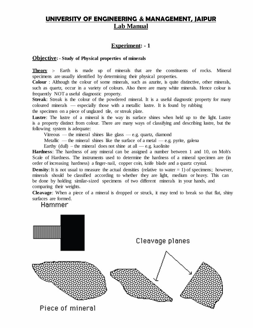
UNIVERSITY OF ENGINEERING amp MANAGEMENT JAIPUR Lab Manual
EXPERIMENT-3
OBJECTIVES - Study of Crystals
VOCABULARY
i Conglomerate
ii Gneiss
iii Granite iv Marble
v Obsidian
vi Sandstone
vii Schist
viii Scoria
ix Shale
MATERIALS i Identification sheets made in pre lab
ii Rocks iii 10 HCL Solution (Optional)
Theory-
Rocks record the earthrsquos history when those rocks where formed When students get a piece of rock in lab they need to associate different environments of sedimentary igneous and
metamorphic Although sedimentary is the most common rock found on the surface of
earth students can most of the groups very easily It is very common for building and see
the different types of rocks even if they did not form in that city Discuss with the students that rocks have key characteristics just like minerals but that identifying rocks is much more difficult in this lab they will become familiar with the key characteristics of small group of sedimentary igneous and metamorphic
PROCEDURE-
1 Review the rocks on the pre lab identification sheets You may want to go over some of
the characteristics described below
BLACK GLASSY - black-the color glassy - have students imagine broken glass RED HOLES - red-the color holes - like Swiss cheese LARGE MINERALS - visible obvious minerals
WHITE FLAT LIGHT - white-the color flat - as a pancake _ like a balloon
PEBBLES GLUED - sand size sand grains look like they are pasted together FLAT LAYERS - pancakes stacked on top of each other SHINY - like a new car
WHITE AND GRAY MINERALS - the minerals are large enough to see and are white and
gray fizz - if you have dilute HCl(can be bought in a hardware store as Muriatic Acid -
UNIVERSITY OF ENGINEERING AND MANAGEMENT JAIPUR Lab Manual
Cement Cleaner) pour just a drop on a specimen so students can see it fizz (DO NOT LET
CHILDREN PLAY WITH HCl)
2 See if the students can match the rocks in their packets with the characteristics on the identification sheet Frequently check on their process as they decide which rock belongs
where
3 Discuss with students which rocks belong to which group as grouped below
IGNEOUS - granite scoria obsidian
SEDIMENTARY - sandstone conglomerate shale
METAMORPHIC - marble schist gneiss
Physical Properties of rocks-
i) Hardness - A scratch test developed by a German mineralogist Fredriech
Mohs in 1822 is used to determine mineral hardness He developed a hardness scale that helps to identify mineral properties
ii) Color - Color can sometimes be helpful when identifying minerals However some minerals have more than one color like quartz Quartz can be blue brown pink red
purple and almost any other color or it can be totally colorless Therefore geologists have developed a better way of using color as an identifying property This property
is called a streak iii) Streak - Streak is the name given to the colored residue left by scratching a mineral
across an abrasive surface such as a tile of unglazed porcelain The streak may not
always be the same color you see in the hand specimen A mineral with more than one color will always leave a certain color of streak Hematite is a mineral that can be red
brown or black but it will always leave a characteristic reddish brown streak iv) Luster - Another mineral property that geologists use to identify minerals is luster
Luster is the way in which the surface of a mineral reflects light There are two main types of luster metallic and nonmetallic A metallic luster is shiny and similar to the reflection from a metal object such as a faucet A mineral that does not shine like metal has a
nonmetallic luster For example the wall has a nonmetallic luster v) Cleavage - Cleavage is another property used to distinguish minerals Cleavage is the
tendency for minerals to break along flat planar surfaces Cleavage is rated as good fair and poor depending on the quality of the flat surface produced Mica for example is a
mineral that has good cleavage
vi) Chemical Reaction - A weak acid is used to tell if rocks or minerals contain calcium
carbonate (CaCO3) If the specimen fizzes (giving off CO2) when it comes in contact with acid it is considered carbonate rich If it does not contain calcium carbonate it will not
fizz Calcite and aragonite are two minerals that will always fizz
UNIVERSITY OF ENGINEERING AND MANAGEMENT JAIPUR Lab Manual
EXPERIMENT - 4
Objective - Study of Rock and Minerals
MINERALS
QUARTZ (Sio2)
Habit and crystal system Crystalline and hexagonal system
Colour Variety colourless transparent snow white
Scratch ability and hardness Cannot be scratched by knife H=25 to 27
Streak White
Cleavage Nil
Fracture Uneven at place conchoidal
Specific gravity Crystalline habit horizontal faces piezo electric absence of
cleavage through crystalline breaks with sharp cutting edges
conchoidal faces
Uses Importance Important rare forming mineral 7th standard mineral in Mohrrsquos
scale glass making electronic lenses wireless apparatus
radar watches and clocks industrial and agro granules and
powder glass cutting
OPAL
(Sio2H2O)
Habit and crystal system Massive
Colour and luster Milk white dirty white resinous
Scratch ability and hardness Cannot be scratched by knife H=45 to 55
Streak White
Cleavage Nil
Fracture Uneven at Many places conchoidal
Specific gravity Low 19 to 23
Special properties Resembles Magnetic alkali gravity some varieties
Uses Importance Filler translucent variety cats eye used in jewellery
UNIVERSITY OF ENGINEERING AND MANAGEMENT JAIPUR Lab Manual
MAGNETITE
(Fe304)
Habit and crystal system Crystalline isometric system octahedron and also
massive
Colour and luster Iron Block Metallic
Scratch ability and hardness It cannot be scratched by knife hardness H=55
Streak Block
Cleavage Four sets of oblique cleavage massive
Fracture Uneven
Specific gravity High 55
Special properties Strongly Magnetic
Uses Importance Ore of Iron Ferrite rod radio Antenna
HEMATITE
(Fe203)
Habit and crystal system Crystalline hexagonal and massive
Colour and luster When fresh bright steel gray when altered reddish brown
metallic
Scratch ability and hardness It cannot be scratched and hardness H = 55
Streak Reddish brown cherry brown
Cleavage Oblique cleavage
Fracture Uneven
Specific gravity High 55
Special properties Heavy cherry red colour some varieties are magnetic due to
branches of magnetic
Uses Importance Ore of Iron dyes
BAUXITE
(Al2032H20)
Habit and crystal system Massive commonly pisolitic
Colour and luster Dry white stained reddish brown yellowish by wides
dull sometimes resinous
Scratch ability and hardness Can be scratch easily by knife
Streak White
UNIVERSITY OF ENGINEERING AND MANAGEMENT JAIPUR Lab Manual
Cleavage Nil
Fracture Uneven earthy
Specific gravity Low 23 to 25 Special properties Pisolitic habit some varieties low specific gravity
Uses Importance Chief ore of alumina oil refining bauxite cement
refractory bricks water purification paper making
ceramics chemicals mineral salts
MUSCOVITE MICA [H2KAL3
(sio4)3]
Habit and crystal system Flaky monoclinic system pseudo hexagonal
Colour and luster Colourless transparent silver white in bulk with dark
brown pearly
Scratch ability and hardness Scratched by fingernail and hardness H = 2 ndash 25
Streak White shining
Cleavage One set of perfect basal cleavage
Fracture Uneven
Specific gravity Medium 27 to 3
Special properties Extremely thin elastic transparent Colourless flakes bad
conductor of elasticity
Uses Importance Electric and electrical isolator gas light Chimes
fancy points ornaments
BLOTITE MICA
Habit and crystal system Flaky Monoclinic system pseudo hexagonal
Colour and huster Brownish block transparent
Scratch ability and hardness Scratched by nail and hardness H = 2 to 25
Streak Pale yellow
Cleavage One set of perfect basal cleavage
Fracture Uneven
Specific gravity Medium 29 to 31
Special properties Brownish block to black colour
Uses Importance Important rock forming minerals boiler
UNIVERSITY OF ENGINEERING AND MANAGEMENT JAIPUR Lab Manual
ORTHOCLASE [FELDSPAR
[KAL(Si308)]
Habit and crystal system Massive commonly monoclinic system
Colour and luster White Pink Vitreous
Scratch ability and hardness Cannot be scratched by knife and hardness [H = 6]
Streak White
Cleavage Two sets perpendicular
Fracture Uneven
Specific gravity Medium 26
Special properties Alkaline 2 sets perpendicular
Uses Importance 6 standard mineral in Mohrrsquos scale glass making
AUGITE [Complex silicate of Ca Al Mg
F3]
Habit and crystal system Crystalline monoclinic system crystals are short and
shout eight sided cubical cleavage fracture
Colour and luster Dark gray greyish block block vitreous
Scratch ability and hardness Can be scratched by knife and harness H = 55
Streak greenish white
Cleavage 2 sets almost perpendicular
Fracture Uneven
Specific gravity Medium 32 to 35
Special properties Nearly perpendicular cleavage
Uses Importance Important rock forming mineral
UNIVERSITY OF ENGINEERING AND MANAGEMENT JAIPUR Lab Manual
CALCITE
(CaC03)
Habit and crystal system Crystalline hexagonal system
Colour and luster White grey pink transulent colourless transparent
Scratch ability and hardness Scratched easily by knife and hardness H = 3
Streak White
Cleavage 3 sets of oblique perfect Rhombo hedral
Fracture Uneven
Specific gravity Medium 27
Special properties Perfect Rhombo hedral cleavags reacts readily with
dilute - HCL
Uses Importants Third standard mineral on Mohrrsquos scale of hardness
polarizing mica microscopes Co2 calcium carbide nitro
line cost lime nitrogen bleaching powder soil tooth
paste glass flux in smelting
GARNET (Complex silicate of Ca mg amp fe)
Habit and crystal system Crystalline Isometric system Decahydral system
Colour and luster Brownish block Reddish brown honey brown when fresh
vitreous to metallic
Scratch ability and hardness Canrsquot be scratched by knife and hardness H = 65 to 75
Streak Reddish brown when altered
Cleavage Inter obtained very distinct parallel to deca hydral faces
Fracture Uneven
Specific gravity Medium to high 32 to 45
Special properties Crystal frequently distributed
Uses Importance ceramic stones
UNIVERSITY OF ENGINEERING AND MANAGEMENT JAIPUR Lab Manual
TALC
Habit and crystal system Massive Foliated
Colour and luster Pale green Apple green pearly
Scratch ability and hardness It can be scratched by knife and hardness H = 1 ndash 15
Streak Pale white Cleavage Nil
Fracture Uneven
Specific gravity Medium 27 to 28
Special properties Very soft and smooth
Uses Importance 1st standard mineral in Mohrrsquos scale of hardness filer material
DOLOMITE
Habit and crystal system Crystalline hexagonal system
Colour and luster White grey pink colourless transparent pearly
Scratch ability and hardness Can be scratched by knife and hardness H = 3
Streak White
Cleavage 3 sets of oblique perfect Rhombo - hydral
Fracture Uneven
Specific gravity Medium 27
Special properties Rhombo hydral cleavage colourless varieties
Uses Importance 3rd standard mineral in Mohrrsquos scale of hardness
MAGNESITE
(MgCo3)
Habit and crystal system Crystalline
Colour and luster White grey pink and pearly
Scratch ability and hardness Scratched with knife and hardness H = 35 to 4
Streak White
Cleavage 3 sets of oblique cleavage Rhombo hedron
Fracture Uneven
Specific gravity Medium 17 to 18
Special properties Pearly Luster Reacts with concentrated - HCL
Uses Importance Refractory at 17000c special cements
UNIVERSITY OF ENGINEERING AND MANAGEMENT JAIPUR Lab Manual
GALENA
(pbs)
Habit and crystal system Crystalline Isometric system cubes
Colour and luster Lead grey silver grey bright and metallic
Scratch ability and hardness Can be scratched easily by knife and
hardness H = 2 to 25
Streak Lead grey
Specific gravity Medium 28
Special properties Soft heavy and diamagnetic
Uses Importance Ore of heal Alloys crystals used in Radio sets heavy
aggregate concrete for protective walls in atomic and
Nuclear Reactors
OLIVINE
Habit amp Coastal system Massive
Colour amp Iusture Olive green Lusture (dull)
Scratch ability amp Hardness Hardness (6-7) cannot be scratched y knife
Streak Light green pale colour
Cleavage Absent
Fracture Uneven
Specific gravity Medium (32 ndash 35)
Special properties Commonly unsaturated mineral
Uses (or) Importance - - -
UNIVERSITY OF ENGINEERING AND MANAGEMENT JAIPUR Lab Manual
ASBESTOS
Habit amp Coastal system Fibrous
Colour amp Iusture Pale green silky
Scratch ability amp Hardness Can be scratched by knife amp hardness (2-25)
Streak Nil
Cleavage Nil
Fracture Nil
Specific gravity 2-22
Special properties Fibre Fine Strong Easily separated Fire proof Heat
proof
Uses (or) Importance Asbestos break amp clutch theatres curtains damp proof
structures paper air amp as it filtration
UNIVERSITY OF ENGINEERING AND MANAGEMENT JAIPUR Lab Manual
EXPERIMENT - 5
Objective - To Study various rock forming minerals
Procedure
To identify a rock three things must be considered (1) Origin (2) Composition (3) Texture
Rock Origin The first step to identify a rock is to try categorizing the rock into of the three main
types or group of rocks These include igneous sedimentary and metamorphic types The only
rocks which do not fall into one of these categories are meteorites Igneous sedimentary and
metamorphic rock tupes are distinguished by the processes of their formation
Rock Composition The rock composition is determined by the identification of mineral make up
the rock By the identification a rock is a solid mass or compound consisting of at least two
minerals (although there are some exceptions when a rock may consist entirely of one mineral)
The minerals comprising the rock cab be identified using common field testing method for
individual minerals particularly where the texture is sufficiently coarse grained enough to
distinguish the individual minerals with the naked eye or a hand lens Where the grain sizes of the
minerals comprising the rock are too fine grained to recognize identification in many cases
Rock Texture The texture of a rock is defined by observing two criteria 1) grain size 2) grain
shapes
Grain Size it is the average size of the mineral grains The size scales used for sedimentary
igneous and metamorphic rock are different
Grain Shape It is the general shape of the mineral grain (crystal faces evident or crystals are
rounded)
Rock Type Very Fine grained
Fine Grained Medium Grained
Coarse Grained
Very Coarse Grained
Clastic Sedimentary
06 - 125mm 125 - 25 mm 25 - 5 mm 5 - 1 mm 1 - 2 mm
Metamorphic lt25 mm 25 - 1mm 1 - 2 mm gt 2 mm
Igneous lt 1 mm 1 - 5 mm 5 - 20 mm gt 20 mm
Recognition of Sedimentary Rocks
Hardness Grain Size Other Composition Rock type
Hard Coarse White to brown Foliated
Clean Quartz Sand stone
Hard coarse Quartz and Feldspar Usually very coarse Arkose
Hard to Soft
Mixed Mixed rocks and sediments
Round rocks in finer sediment matrix
Conglomerate
Hard to soft
Mixed Mixed rocks and sediments
Sharp and angular pieces of rocks in finer sediments
matrix
Breccia
UNIVERSITY OF ENGINEERING AND MANAGEMENT JAIPUR Lab Manual
Soft Fine Fizzes with acid Calcite Limestone
Soft Fine Foliated Clay minerals Shale
Hard Fine Chalcedony No fizzing with acid Chert
Hard Fine Feel gritty on teeth Very fine sand no clay Silts tone
Recognition of Igneous Rocks
Grain size Usual color Other Composition Rock type
Coarse Green Dense Approximately 90 to 95 Olivine
Dunite
Fine Dark Contain Quartz Low - silica lava Basalt
Coarse Light Wide range of color and grain
size
Large grains of quartz feldspar Olivine and
pyroxene
Granite
Coarse Medium to dark
Little or no Quartz Plagioclase and dark mineral Diorite
Coarse light Wide range of color and grain
size but no Quartz
Feldspar with Pyroxene amphibole and mica
Syenite
Coarse Medium to dark
Quartz may have Olivine
Calcium Plagioclase and dark minerals
Gabbro
Fine Medium Between felsites and basalt
Medium Silica Lava Andesite
Fine Light Contain Quartz High Silica Lava Felsites
Recognition of Metamorphic Rocks
Grain Size
Hardness Foliation Usual Color Other Rock Type
Coarse Hard Foliated Mixed dark and light
wrinkled foliation often has large crystal
Schist
Coarse Hard Foliated Mixed Banded Gneiss
Fine Soft Foliated Dark tink when struck Slate
Coarse Soft Nonfoliated light Calcite or dolomite by the acid test
Marble
Coarse Hard Nonfoliated light Quartz (no fizzing with acid)
Ouartzite
UNIVERSITY OF ENGINEERING AND MANAGEMENT JAIPUR Lab Manual
Fine Soft Foliated Dark Shiny Crinkly foliation Phyllite
Coarse Hard Foliated Dark Mostly hornblende Amphibolite
Coarse Hard Foliated Mixed Distored metled layer Migmatite
Viva Quations - 1 What is Rock
2 Properties of Rocks 3 What is the Classification of Rocks
UNIVERSITY OF ENGINEERING AND MANAGEMENT JAIPUR Lab Manual
EXPERIMENT-6
Objective-Study of Geological map interpretation of geological structures
Theory-A cross section should be consistent with all the available data although there are often several viable interpretations of the same data Most cross sections are drawn
to true scale that is where the horizontal scale is the same as the vertical scale This
means the true dip of the rock units are shown Vertical exaggeration where the vertical scale is increased relative to the horizontal is sometimes used to make a cross section
clearer However it also increases the dips of the rock units exaggerating the geological
structures
Procedure-
Step 1 Determine the line along which to draw the section The line of section should be representative
of the study area be perpendicular to the major structural feature of the area (eg large scale folds or faults) cross as many structural features as possible and run through areas with the most data readings
UNIVERSITY OF ENGINEERING AND MANAGEMENT JAIPUR Lab Manual
Step 2
Draw axes of an appropriate scale with theopographic values Unless there is a reason todo otherwise
draw a true-scale section
Step 3
Transfer the topographic information from the map to the section Project the height of each
topographic contour where it crosses the line of section on to the section and draw in
The topography
Step 4 Transfer the lithological boundaries faults etc onto the cross section in the same way
Step 5
Transfer bedding readings on to the section correcting for apparent dip if necessary (see figure)
Plot the readings at the height at which they occur so where a reading is
extrapolated from a greater or lesser height than the topography of the cross section plot it above or below the topography as appropriate
UNIVERSITY OF ENGINEERING AND MANAGEMENT JAIPUR Lab Manual
Step 6
Using the bedding readings as a guide draw in the lithological boundaries both above and
below the surface Geology extended above the topography is shown by dashed lines When drawing the section always consider what is geologically reasonable behavior for the
Layers eg sudden changes in a unitrsquos thickness or dip should be justifiable
UNIVERSITY OF ENGINEERING AND MANAGEMENT JAIPUR Lab Manual
Theory-If the Earthrsquos surface was flat if there was no topography then geological maps would be simple They would be a direct reflection of the underlying geology However topography interacts with the geology to produce more complex but predictable patterns
Horizontal and vertical strata
Horizontal and vertical strata are the most straight forward to interpret on a map Horizontal
outcrops will always follow the topographic contours (figure 2a) whilst vertical layers will always form straight lines (figure2b) Dipping strata
Dipping layers interact with the topography in predictable ways In valleys beds will appear to lsquoveersquo either up or down the valley in the direction of dip (figure 2c and 2d) This is because the
valley side acts as an approximate cross sectionndashnot always helpful on small scale maps but on
large scale maps and in the field this is a useful aid in interpretation
UNIVERSITY OF ENGINEERING AND MANAGEMENT JAIPUR Lab Manual
A Folding of rocks
a Layer cake relations
(1) Oldest on bottom youngest on top b Fold Types
(1) Anticlines-upfolded forms results in older rocks becoming enclosed within
younger strata
(2) synclines-downfolded forms results in younger rocks becoming enclosed within
older strata (3) Symmetrical folds- both limbs of the fold dipping at same angle away from fold axis
(4) Asymmetrical folds- both limbs of the fold not dipping at same angle away from fold axis
(5) Overturned folds- condition in which one limb of fold has been tilted beyond
vertical
(6) Plunging folds- axis of fold is tilted
(7) Domes- more or less circular equivalent of anticline oldest rocks exposed in center of dome
(8) Structural Basin- more or less circular equivalent of syncline youngest rocks exposed in center of dome (not to be confused with depositional basin)
c Outcrops Patterns Associated with Folded Rocks
(1) As rocks are folded and subsequently subjected to erosion regular patterns become
evident in relation to type of rock that outcrops and age of the rock that outcrops in
an area of folded strata In essence erosion exposes the interiors of the folds
(2) Non-plunging Folds- axis of fold is horizontal results in parallel bands of dipping strata
about the fold axis
(a) anticlines- oldest strata exposed along fold axis (b) synclines- youngest strata exposed along fold axis
(3)Plunging Folds-axis of fold is tilted results in alternating V-shaped bands of dipping strata oriented about the fold axis (a) anticlines- oldest strata exposed in the center of the V V points in direction of plunge of fold axis
(b) syncline- youngest strata exposed in the center of the V V points in opposite direction of plunge of fold axis
(4) Doubly Plunging Folds- fold axis is plunging in two opposite directions results in a
flattened oval pattern or a double V-shaped pattern ltltltgtgtgtgt
(a) anticlines- oldest strata exposed in center of flattened oval (b) synclines-youngest strata exposed in center of flattened oval
UNIVERSITY OF ENGINEERING AND MANAGEMENT JAIPUR Lab Manual
Faults on maps-Faults can occur at any angle with respect to bedding and so the
outcrop patterns produced are not unique to any one fault type Figure a and b show two potential outcrop patterns for a normal fault
Fold on maps - Figure shows the different outcrop patterns for folds The limbs of the
folds form a repeating pattern on either side of the axial plane For anticlines the oldest rocks are in core of the fold and the rocks get younger away from the axial trace (figure a) For synclines the youngest rocks are in the core and the rocks get older
away from the axial trace (figure b)
Plunging folds form the same repeating pattern as non-plunging folds except their limbs
converge around the axial traces The limbs of synclines open in the direction they plunge (figure c) whilst the limbs of anticlines close in the direction they plunge (figure d)
Viva Questions-
1 What do you mean by Geological Map 2 What are lithological boundaries
3 What do you mean by Scale 4 What is Fault 5 What is Fold
6 What do you mean by Syncline and anticyline

UNIVERSITY OF ENGINEERING AND MANAGEMENT JAIPUR Lab Manual
Cleavage Nil
Fracture Uneven earthy
Specific gravity Low 23 to 25 Special properties Pisolitic habit some varieties low specific gravity
Uses Importance Chief ore of alumina oil refining bauxite cement
refractory bricks water purification paper making
ceramics chemicals mineral salts
MUSCOVITE MICA [H2KAL3
(sio4)3]
Habit and crystal system Flaky monoclinic system pseudo hexagonal
Colour and luster Colourless transparent silver white in bulk with dark
brown pearly
Scratch ability and hardness Scratched by fingernail and hardness H = 2 ndash 25
Streak White shining
Cleavage One set of perfect basal cleavage
Fracture Uneven
Specific gravity Medium 27 to 3
Special properties Extremely thin elastic transparent Colourless flakes bad
conductor of elasticity
Uses Importance Electric and electrical isolator gas light Chimes
fancy points ornaments
BLOTITE MICA
Habit and crystal system Flaky Monoclinic system pseudo hexagonal
Colour and huster Brownish block transparent
Scratch ability and hardness Scratched by nail and hardness H = 2 to 25
Streak Pale yellow
Cleavage One set of perfect basal cleavage
Fracture Uneven
Specific gravity Medium 29 to 31
Special properties Brownish block to black colour
Uses Importance Important rock forming minerals boiler
UNIVERSITY OF ENGINEERING AND MANAGEMENT JAIPUR Lab Manual
ORTHOCLASE [FELDSPAR
[KAL(Si308)]
Habit and crystal system Massive commonly monoclinic system
Colour and luster White Pink Vitreous
Scratch ability and hardness Cannot be scratched by knife and hardness [H = 6]
Streak White
Cleavage Two sets perpendicular
Fracture Uneven
Specific gravity Medium 26
Special properties Alkaline 2 sets perpendicular
Uses Importance 6 standard mineral in Mohrrsquos scale glass making
AUGITE [Complex silicate of Ca Al Mg
F3]
Habit and crystal system Crystalline monoclinic system crystals are short and
shout eight sided cubical cleavage fracture
Colour and luster Dark gray greyish block block vitreous
Scratch ability and hardness Can be scratched by knife and harness H = 55
Streak greenish white
Cleavage 2 sets almost perpendicular
Fracture Uneven
Specific gravity Medium 32 to 35
Special properties Nearly perpendicular cleavage
Uses Importance Important rock forming mineral
UNIVERSITY OF ENGINEERING AND MANAGEMENT JAIPUR Lab Manual
CALCITE
(CaC03)
Habit and crystal system Crystalline hexagonal system
Colour and luster White grey pink transulent colourless transparent
Scratch ability and hardness Scratched easily by knife and hardness H = 3
Streak White
Cleavage 3 sets of oblique perfect Rhombo hedral
Fracture Uneven
Specific gravity Medium 27
Special properties Perfect Rhombo hedral cleavags reacts readily with
dilute - HCL
Uses Importants Third standard mineral on Mohrrsquos scale of hardness
polarizing mica microscopes Co2 calcium carbide nitro
line cost lime nitrogen bleaching powder soil tooth
paste glass flux in smelting
GARNET (Complex silicate of Ca mg amp fe)
Habit and crystal system Crystalline Isometric system Decahydral system
Colour and luster Brownish block Reddish brown honey brown when fresh
vitreous to metallic
Scratch ability and hardness Canrsquot be scratched by knife and hardness H = 65 to 75
Streak Reddish brown when altered
Cleavage Inter obtained very distinct parallel to deca hydral faces
Fracture Uneven
Specific gravity Medium to high 32 to 45
Special properties Crystal frequently distributed
Uses Importance ceramic stones
UNIVERSITY OF ENGINEERING AND MANAGEMENT JAIPUR Lab Manual
TALC
Habit and crystal system Massive Foliated
Colour and luster Pale green Apple green pearly
Scratch ability and hardness It can be scratched by knife and hardness H = 1 ndash 15
Streak Pale white Cleavage Nil
Fracture Uneven
Specific gravity Medium 27 to 28
Special properties Very soft and smooth
Uses Importance 1st standard mineral in Mohrrsquos scale of hardness filer material
DOLOMITE
Habit and crystal system Crystalline hexagonal system
Colour and luster White grey pink colourless transparent pearly
Scratch ability and hardness Can be scratched by knife and hardness H = 3
Streak White
Cleavage 3 sets of oblique perfect Rhombo - hydral
Fracture Uneven
Specific gravity Medium 27
Special properties Rhombo hydral cleavage colourless varieties
Uses Importance 3rd standard mineral in Mohrrsquos scale of hardness
MAGNESITE
(MgCo3)
Habit and crystal system Crystalline
Colour and luster White grey pink and pearly
Scratch ability and hardness Scratched with knife and hardness H = 35 to 4
Streak White
Cleavage 3 sets of oblique cleavage Rhombo hedron
Fracture Uneven
Specific gravity Medium 17 to 18
Special properties Pearly Luster Reacts with concentrated - HCL
Uses Importance Refractory at 17000c special cements
UNIVERSITY OF ENGINEERING AND MANAGEMENT JAIPUR Lab Manual
GALENA
(pbs)
Habit and crystal system Crystalline Isometric system cubes
Colour and luster Lead grey silver grey bright and metallic
Scratch ability and hardness Can be scratched easily by knife and
hardness H = 2 to 25
Streak Lead grey
Specific gravity Medium 28
Special properties Soft heavy and diamagnetic
Uses Importance Ore of heal Alloys crystals used in Radio sets heavy
aggregate concrete for protective walls in atomic and
Nuclear Reactors
OLIVINE
Habit amp Coastal system Massive
Colour amp Iusture Olive green Lusture (dull)
Scratch ability amp Hardness Hardness (6-7) cannot be scratched y knife
Streak Light green pale colour
Cleavage Absent
Fracture Uneven
Specific gravity Medium (32 ndash 35)
Special properties Commonly unsaturated mineral
Uses (or) Importance - - -
UNIVERSITY OF ENGINEERING AND MANAGEMENT JAIPUR Lab Manual
ASBESTOS
Habit amp Coastal system Fibrous
Colour amp Iusture Pale green silky
Scratch ability amp Hardness Can be scratched by knife amp hardness (2-25)
Streak Nil
Cleavage Nil
Fracture Nil
Specific gravity 2-22
Special properties Fibre Fine Strong Easily separated Fire proof Heat
proof
Uses (or) Importance Asbestos break amp clutch theatres curtains damp proof
structures paper air amp as it filtration
UNIVERSITY OF ENGINEERING AND MANAGEMENT JAIPUR Lab Manual
EXPERIMENT - 5
Objective - To Study various rock forming minerals
Procedure
To identify a rock three things must be considered (1) Origin (2) Composition (3) Texture
Rock Origin The first step to identify a rock is to try categorizing the rock into of the three main
types or group of rocks These include igneous sedimentary and metamorphic types The only
rocks which do not fall into one of these categories are meteorites Igneous sedimentary and
metamorphic rock tupes are distinguished by the processes of their formation
Rock Composition The rock composition is determined by the identification of mineral make up
the rock By the identification a rock is a solid mass or compound consisting of at least two
minerals (although there are some exceptions when a rock may consist entirely of one mineral)
The minerals comprising the rock cab be identified using common field testing method for
individual minerals particularly where the texture is sufficiently coarse grained enough to
distinguish the individual minerals with the naked eye or a hand lens Where the grain sizes of the
minerals comprising the rock are too fine grained to recognize identification in many cases
Rock Texture The texture of a rock is defined by observing two criteria 1) grain size 2) grain
shapes
Grain Size it is the average size of the mineral grains The size scales used for sedimentary
igneous and metamorphic rock are different
Grain Shape It is the general shape of the mineral grain (crystal faces evident or crystals are
rounded)
Rock Type Very Fine grained
Fine Grained Medium Grained
Coarse Grained
Very Coarse Grained
Clastic Sedimentary
06 - 125mm 125 - 25 mm 25 - 5 mm 5 - 1 mm 1 - 2 mm
Metamorphic lt25 mm 25 - 1mm 1 - 2 mm gt 2 mm
Igneous lt 1 mm 1 - 5 mm 5 - 20 mm gt 20 mm
Recognition of Sedimentary Rocks
Hardness Grain Size Other Composition Rock type
Hard Coarse White to brown Foliated
Clean Quartz Sand stone
Hard coarse Quartz and Feldspar Usually very coarse Arkose
Hard to Soft
Mixed Mixed rocks and sediments
Round rocks in finer sediment matrix
Conglomerate
Hard to soft
Mixed Mixed rocks and sediments
Sharp and angular pieces of rocks in finer sediments
matrix
Breccia
UNIVERSITY OF ENGINEERING AND MANAGEMENT JAIPUR Lab Manual
Soft Fine Fizzes with acid Calcite Limestone
Soft Fine Foliated Clay minerals Shale
Hard Fine Chalcedony No fizzing with acid Chert
Hard Fine Feel gritty on teeth Very fine sand no clay Silts tone
Recognition of Igneous Rocks
Grain size Usual color Other Composition Rock type
Coarse Green Dense Approximately 90 to 95 Olivine
Dunite
Fine Dark Contain Quartz Low - silica lava Basalt
Coarse Light Wide range of color and grain
size
Large grains of quartz feldspar Olivine and
pyroxene
Granite
Coarse Medium to dark
Little or no Quartz Plagioclase and dark mineral Diorite
Coarse light Wide range of color and grain
size but no Quartz
Feldspar with Pyroxene amphibole and mica
Syenite
Coarse Medium to dark
Quartz may have Olivine
Calcium Plagioclase and dark minerals
Gabbro
Fine Medium Between felsites and basalt
Medium Silica Lava Andesite
Fine Light Contain Quartz High Silica Lava Felsites
Recognition of Metamorphic Rocks
Grain Size
Hardness Foliation Usual Color Other Rock Type
Coarse Hard Foliated Mixed dark and light
wrinkled foliation often has large crystal
Schist
Coarse Hard Foliated Mixed Banded Gneiss
Fine Soft Foliated Dark tink when struck Slate
Coarse Soft Nonfoliated light Calcite or dolomite by the acid test
Marble
Coarse Hard Nonfoliated light Quartz (no fizzing with acid)
Ouartzite
UNIVERSITY OF ENGINEERING AND MANAGEMENT JAIPUR Lab Manual
Fine Soft Foliated Dark Shiny Crinkly foliation Phyllite
Coarse Hard Foliated Dark Mostly hornblende Amphibolite
Coarse Hard Foliated Mixed Distored metled layer Migmatite
Viva Quations - 1 What is Rock
2 Properties of Rocks 3 What is the Classification of Rocks
UNIVERSITY OF ENGINEERING AND MANAGEMENT JAIPUR Lab Manual
EXPERIMENT-6
Objective-Study of Geological map interpretation of geological structures
Theory-A cross section should be consistent with all the available data although there are often several viable interpretations of the same data Most cross sections are drawn
to true scale that is where the horizontal scale is the same as the vertical scale This
means the true dip of the rock units are shown Vertical exaggeration where the vertical scale is increased relative to the horizontal is sometimes used to make a cross section
clearer However it also increases the dips of the rock units exaggerating the geological
structures
Procedure-
Step 1 Determine the line along which to draw the section The line of section should be representative
of the study area be perpendicular to the major structural feature of the area (eg large scale folds or faults) cross as many structural features as possible and run through areas with the most data readings
UNIVERSITY OF ENGINEERING AND MANAGEMENT JAIPUR Lab Manual
Step 2
Draw axes of an appropriate scale with theopographic values Unless there is a reason todo otherwise
draw a true-scale section
Step 3
Transfer the topographic information from the map to the section Project the height of each
topographic contour where it crosses the line of section on to the section and draw in
The topography
Step 4 Transfer the lithological boundaries faults etc onto the cross section in the same way
Step 5
Transfer bedding readings on to the section correcting for apparent dip if necessary (see figure)
Plot the readings at the height at which they occur so where a reading is
extrapolated from a greater or lesser height than the topography of the cross section plot it above or below the topography as appropriate
UNIVERSITY OF ENGINEERING AND MANAGEMENT JAIPUR Lab Manual
Step 6
Using the bedding readings as a guide draw in the lithological boundaries both above and
below the surface Geology extended above the topography is shown by dashed lines When drawing the section always consider what is geologically reasonable behavior for the
Layers eg sudden changes in a unitrsquos thickness or dip should be justifiable
UNIVERSITY OF ENGINEERING AND MANAGEMENT JAIPUR Lab Manual
Theory-If the Earthrsquos surface was flat if there was no topography then geological maps would be simple They would be a direct reflection of the underlying geology However topography interacts with the geology to produce more complex but predictable patterns
Horizontal and vertical strata
Horizontal and vertical strata are the most straight forward to interpret on a map Horizontal
outcrops will always follow the topographic contours (figure 2a) whilst vertical layers will always form straight lines (figure2b) Dipping strata
Dipping layers interact with the topography in predictable ways In valleys beds will appear to lsquoveersquo either up or down the valley in the direction of dip (figure 2c and 2d) This is because the
valley side acts as an approximate cross sectionndashnot always helpful on small scale maps but on
large scale maps and in the field this is a useful aid in interpretation
UNIVERSITY OF ENGINEERING AND MANAGEMENT JAIPUR Lab Manual
A Folding of rocks
a Layer cake relations
(1) Oldest on bottom youngest on top b Fold Types
(1) Anticlines-upfolded forms results in older rocks becoming enclosed within
younger strata
(2) synclines-downfolded forms results in younger rocks becoming enclosed within
older strata (3) Symmetrical folds- both limbs of the fold dipping at same angle away from fold axis
(4) Asymmetrical folds- both limbs of the fold not dipping at same angle away from fold axis
(5) Overturned folds- condition in which one limb of fold has been tilted beyond
vertical
(6) Plunging folds- axis of fold is tilted
(7) Domes- more or less circular equivalent of anticline oldest rocks exposed in center of dome
(8) Structural Basin- more or less circular equivalent of syncline youngest rocks exposed in center of dome (not to be confused with depositional basin)
c Outcrops Patterns Associated with Folded Rocks
(1) As rocks are folded and subsequently subjected to erosion regular patterns become
evident in relation to type of rock that outcrops and age of the rock that outcrops in
an area of folded strata In essence erosion exposes the interiors of the folds
(2) Non-plunging Folds- axis of fold is horizontal results in parallel bands of dipping strata
about the fold axis
(a) anticlines- oldest strata exposed along fold axis (b) synclines- youngest strata exposed along fold axis
(3)Plunging Folds-axis of fold is tilted results in alternating V-shaped bands of dipping strata oriented about the fold axis (a) anticlines- oldest strata exposed in the center of the V V points in direction of plunge of fold axis
(b) syncline- youngest strata exposed in the center of the V V points in opposite direction of plunge of fold axis
(4) Doubly Plunging Folds- fold axis is plunging in two opposite directions results in a
flattened oval pattern or a double V-shaped pattern ltltltgtgtgtgt
(a) anticlines- oldest strata exposed in center of flattened oval (b) synclines-youngest strata exposed in center of flattened oval
UNIVERSITY OF ENGINEERING AND MANAGEMENT JAIPUR Lab Manual
Faults on maps-Faults can occur at any angle with respect to bedding and so the
outcrop patterns produced are not unique to any one fault type Figure a and b show two potential outcrop patterns for a normal fault
Fold on maps - Figure shows the different outcrop patterns for folds The limbs of the
folds form a repeating pattern on either side of the axial plane For anticlines the oldest rocks are in core of the fold and the rocks get younger away from the axial trace (figure a) For synclines the youngest rocks are in the core and the rocks get older
away from the axial trace (figure b)
Plunging folds form the same repeating pattern as non-plunging folds except their limbs
converge around the axial traces The limbs of synclines open in the direction they plunge (figure c) whilst the limbs of anticlines close in the direction they plunge (figure d)
Viva Questions-
1 What do you mean by Geological Map 2 What are lithological boundaries
3 What do you mean by Scale 4 What is Fault 5 What is Fold
6 What do you mean by Syncline and anticyline

UNIVERSITY OF ENGINEERING AND MANAGEMENT JAIPUR Lab Manual
ASBESTOS
Habit amp Coastal system Fibrous
Colour amp Iusture Pale green silky
Scratch ability amp Hardness Can be scratched by knife amp hardness (2-25)
Streak Nil
Cleavage Nil
Fracture Nil
Specific gravity 2-22
Special properties Fibre Fine Strong Easily separated Fire proof Heat
proof
Uses (or) Importance Asbestos break amp clutch theatres curtains damp proof
structures paper air amp as it filtration
UNIVERSITY OF ENGINEERING AND MANAGEMENT JAIPUR Lab Manual
EXPERIMENT - 5
Objective - To Study various rock forming minerals
Procedure
To identify a rock three things must be considered (1) Origin (2) Composition (3) Texture
Rock Origin The first step to identify a rock is to try categorizing the rock into of the three main
types or group of rocks These include igneous sedimentary and metamorphic types The only
rocks which do not fall into one of these categories are meteorites Igneous sedimentary and
metamorphic rock tupes are distinguished by the processes of their formation
Rock Composition The rock composition is determined by the identification of mineral make up
the rock By the identification a rock is a solid mass or compound consisting of at least two
minerals (although there are some exceptions when a rock may consist entirely of one mineral)
The minerals comprising the rock cab be identified using common field testing method for
individual minerals particularly where the texture is sufficiently coarse grained enough to
distinguish the individual minerals with the naked eye or a hand lens Where the grain sizes of the
minerals comprising the rock are too fine grained to recognize identification in many cases
Rock Texture The texture of a rock is defined by observing two criteria 1) grain size 2) grain
shapes
Grain Size it is the average size of the mineral grains The size scales used for sedimentary
igneous and metamorphic rock are different
Grain Shape It is the general shape of the mineral grain (crystal faces evident or crystals are
rounded)
Rock Type Very Fine grained
Fine Grained Medium Grained
Coarse Grained
Very Coarse Grained
Clastic Sedimentary
06 - 125mm 125 - 25 mm 25 - 5 mm 5 - 1 mm 1 - 2 mm
Metamorphic lt25 mm 25 - 1mm 1 - 2 mm gt 2 mm
Igneous lt 1 mm 1 - 5 mm 5 - 20 mm gt 20 mm
Recognition of Sedimentary Rocks
Hardness Grain Size Other Composition Rock type
Hard Coarse White to brown Foliated
Clean Quartz Sand stone
Hard coarse Quartz and Feldspar Usually very coarse Arkose
Hard to Soft
Mixed Mixed rocks and sediments
Round rocks in finer sediment matrix
Conglomerate
Hard to soft
Mixed Mixed rocks and sediments
Sharp and angular pieces of rocks in finer sediments
matrix
Breccia
UNIVERSITY OF ENGINEERING AND MANAGEMENT JAIPUR Lab Manual
Soft Fine Fizzes with acid Calcite Limestone
Soft Fine Foliated Clay minerals Shale
Hard Fine Chalcedony No fizzing with acid Chert
Hard Fine Feel gritty on teeth Very fine sand no clay Silts tone
Recognition of Igneous Rocks
Grain size Usual color Other Composition Rock type
Coarse Green Dense Approximately 90 to 95 Olivine
Dunite
Fine Dark Contain Quartz Low - silica lava Basalt
Coarse Light Wide range of color and grain
size
Large grains of quartz feldspar Olivine and
pyroxene
Granite
Coarse Medium to dark
Little or no Quartz Plagioclase and dark mineral Diorite
Coarse light Wide range of color and grain
size but no Quartz
Feldspar with Pyroxene amphibole and mica
Syenite
Coarse Medium to dark
Quartz may have Olivine
Calcium Plagioclase and dark minerals
Gabbro
Fine Medium Between felsites and basalt
Medium Silica Lava Andesite
Fine Light Contain Quartz High Silica Lava Felsites
Recognition of Metamorphic Rocks
Grain Size
Hardness Foliation Usual Color Other Rock Type
Coarse Hard Foliated Mixed dark and light
wrinkled foliation often has large crystal
Schist
Coarse Hard Foliated Mixed Banded Gneiss
Fine Soft Foliated Dark tink when struck Slate
Coarse Soft Nonfoliated light Calcite or dolomite by the acid test
Marble
Coarse Hard Nonfoliated light Quartz (no fizzing with acid)
Ouartzite
UNIVERSITY OF ENGINEERING AND MANAGEMENT JAIPUR Lab Manual
Fine Soft Foliated Dark Shiny Crinkly foliation Phyllite
Coarse Hard Foliated Dark Mostly hornblende Amphibolite
Coarse Hard Foliated Mixed Distored metled layer Migmatite
Viva Quations - 1 What is Rock
2 Properties of Rocks 3 What is the Classification of Rocks
UNIVERSITY OF ENGINEERING AND MANAGEMENT JAIPUR Lab Manual
EXPERIMENT-6
Objective-Study of Geological map interpretation of geological structures
Theory-A cross section should be consistent with all the available data although there are often several viable interpretations of the same data Most cross sections are drawn
to true scale that is where the horizontal scale is the same as the vertical scale This
means the true dip of the rock units are shown Vertical exaggeration where the vertical scale is increased relative to the horizontal is sometimes used to make a cross section
clearer However it also increases the dips of the rock units exaggerating the geological
structures
Procedure-
Step 1 Determine the line along which to draw the section The line of section should be representative
of the study area be perpendicular to the major structural feature of the area (eg large scale folds or faults) cross as many structural features as possible and run through areas with the most data readings
UNIVERSITY OF ENGINEERING AND MANAGEMENT JAIPUR Lab Manual
Step 2
Draw axes of an appropriate scale with theopographic values Unless there is a reason todo otherwise
draw a true-scale section
Step 3
Transfer the topographic information from the map to the section Project the height of each
topographic contour where it crosses the line of section on to the section and draw in
The topography
Step 4 Transfer the lithological boundaries faults etc onto the cross section in the same way
Step 5
Transfer bedding readings on to the section correcting for apparent dip if necessary (see figure)
Plot the readings at the height at which they occur so where a reading is
extrapolated from a greater or lesser height than the topography of the cross section plot it above or below the topography as appropriate
UNIVERSITY OF ENGINEERING AND MANAGEMENT JAIPUR Lab Manual
Step 6
Using the bedding readings as a guide draw in the lithological boundaries both above and
below the surface Geology extended above the topography is shown by dashed lines When drawing the section always consider what is geologically reasonable behavior for the
Layers eg sudden changes in a unitrsquos thickness or dip should be justifiable
UNIVERSITY OF ENGINEERING AND MANAGEMENT JAIPUR Lab Manual
Theory-If the Earthrsquos surface was flat if there was no topography then geological maps would be simple They would be a direct reflection of the underlying geology However topography interacts with the geology to produce more complex but predictable patterns
Horizontal and vertical strata
Horizontal and vertical strata are the most straight forward to interpret on a map Horizontal
outcrops will always follow the topographic contours (figure 2a) whilst vertical layers will always form straight lines (figure2b) Dipping strata
Dipping layers interact with the topography in predictable ways In valleys beds will appear to lsquoveersquo either up or down the valley in the direction of dip (figure 2c and 2d) This is because the
valley side acts as an approximate cross sectionndashnot always helpful on small scale maps but on
large scale maps and in the field this is a useful aid in interpretation
UNIVERSITY OF ENGINEERING AND MANAGEMENT JAIPUR Lab Manual
A Folding of rocks
a Layer cake relations
(1) Oldest on bottom youngest on top b Fold Types
(1) Anticlines-upfolded forms results in older rocks becoming enclosed within
younger strata
(2) synclines-downfolded forms results in younger rocks becoming enclosed within
older strata (3) Symmetrical folds- both limbs of the fold dipping at same angle away from fold axis
(4) Asymmetrical folds- both limbs of the fold not dipping at same angle away from fold axis
(5) Overturned folds- condition in which one limb of fold has been tilted beyond
vertical
(6) Plunging folds- axis of fold is tilted
(7) Domes- more or less circular equivalent of anticline oldest rocks exposed in center of dome
(8) Structural Basin- more or less circular equivalent of syncline youngest rocks exposed in center of dome (not to be confused with depositional basin)
c Outcrops Patterns Associated with Folded Rocks
(1) As rocks are folded and subsequently subjected to erosion regular patterns become
evident in relation to type of rock that outcrops and age of the rock that outcrops in
an area of folded strata In essence erosion exposes the interiors of the folds
(2) Non-plunging Folds- axis of fold is horizontal results in parallel bands of dipping strata
about the fold axis
(a) anticlines- oldest strata exposed along fold axis (b) synclines- youngest strata exposed along fold axis
(3)Plunging Folds-axis of fold is tilted results in alternating V-shaped bands of dipping strata oriented about the fold axis (a) anticlines- oldest strata exposed in the center of the V V points in direction of plunge of fold axis
(b) syncline- youngest strata exposed in the center of the V V points in opposite direction of plunge of fold axis
(4) Doubly Plunging Folds- fold axis is plunging in two opposite directions results in a
flattened oval pattern or a double V-shaped pattern ltltltgtgtgtgt
(a) anticlines- oldest strata exposed in center of flattened oval (b) synclines-youngest strata exposed in center of flattened oval
UNIVERSITY OF ENGINEERING AND MANAGEMENT JAIPUR Lab Manual
Faults on maps-Faults can occur at any angle with respect to bedding and so the
outcrop patterns produced are not unique to any one fault type Figure a and b show two potential outcrop patterns for a normal fault
Fold on maps - Figure shows the different outcrop patterns for folds The limbs of the
folds form a repeating pattern on either side of the axial plane For anticlines the oldest rocks are in core of the fold and the rocks get younger away from the axial trace (figure a) For synclines the youngest rocks are in the core and the rocks get older
away from the axial trace (figure b)
Plunging folds form the same repeating pattern as non-plunging folds except their limbs
converge around the axial traces The limbs of synclines open in the direction they plunge (figure c) whilst the limbs of anticlines close in the direction they plunge (figure d)
Viva Questions-
1 What do you mean by Geological Map 2 What are lithological boundaries
3 What do you mean by Scale 4 What is Fault 5 What is Fold
6 What do you mean by Syncline and anticyline
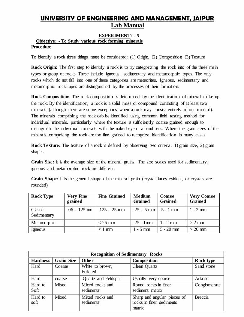
UNIVERSITY OF ENGINEERING AND MANAGEMENT JAIPUR Lab Manual
Fine Soft Foliated Dark Shiny Crinkly foliation Phyllite
Coarse Hard Foliated Dark Mostly hornblende Amphibolite
Coarse Hard Foliated Mixed Distored metled layer Migmatite
Viva Quations - 1 What is Rock
2 Properties of Rocks 3 What is the Classification of Rocks
UNIVERSITY OF ENGINEERING AND MANAGEMENT JAIPUR Lab Manual
EXPERIMENT-6
Objective-Study of Geological map interpretation of geological structures
Theory-A cross section should be consistent with all the available data although there are often several viable interpretations of the same data Most cross sections are drawn
to true scale that is where the horizontal scale is the same as the vertical scale This
means the true dip of the rock units are shown Vertical exaggeration where the vertical scale is increased relative to the horizontal is sometimes used to make a cross section
clearer However it also increases the dips of the rock units exaggerating the geological
structures
Procedure-
Step 1 Determine the line along which to draw the section The line of section should be representative
of the study area be perpendicular to the major structural feature of the area (eg large scale folds or faults) cross as many structural features as possible and run through areas with the most data readings
UNIVERSITY OF ENGINEERING AND MANAGEMENT JAIPUR Lab Manual
Step 2
Draw axes of an appropriate scale with theopographic values Unless there is a reason todo otherwise
draw a true-scale section
Step 3
Transfer the topographic information from the map to the section Project the height of each
topographic contour where it crosses the line of section on to the section and draw in
The topography
Step 4 Transfer the lithological boundaries faults etc onto the cross section in the same way
Step 5
Transfer bedding readings on to the section correcting for apparent dip if necessary (see figure)
Plot the readings at the height at which they occur so where a reading is
extrapolated from a greater or lesser height than the topography of the cross section plot it above or below the topography as appropriate
UNIVERSITY OF ENGINEERING AND MANAGEMENT JAIPUR Lab Manual
Step 6
Using the bedding readings as a guide draw in the lithological boundaries both above and
below the surface Geology extended above the topography is shown by dashed lines When drawing the section always consider what is geologically reasonable behavior for the
Layers eg sudden changes in a unitrsquos thickness or dip should be justifiable
UNIVERSITY OF ENGINEERING AND MANAGEMENT JAIPUR Lab Manual
Theory-If the Earthrsquos surface was flat if there was no topography then geological maps would be simple They would be a direct reflection of the underlying geology However topography interacts with the geology to produce more complex but predictable patterns
Horizontal and vertical strata
Horizontal and vertical strata are the most straight forward to interpret on a map Horizontal
outcrops will always follow the topographic contours (figure 2a) whilst vertical layers will always form straight lines (figure2b) Dipping strata
Dipping layers interact with the topography in predictable ways In valleys beds will appear to lsquoveersquo either up or down the valley in the direction of dip (figure 2c and 2d) This is because the
valley side acts as an approximate cross sectionndashnot always helpful on small scale maps but on
large scale maps and in the field this is a useful aid in interpretation
UNIVERSITY OF ENGINEERING AND MANAGEMENT JAIPUR Lab Manual
A Folding of rocks
a Layer cake relations
(1) Oldest on bottom youngest on top b Fold Types
(1) Anticlines-upfolded forms results in older rocks becoming enclosed within
younger strata
(2) synclines-downfolded forms results in younger rocks becoming enclosed within
older strata (3) Symmetrical folds- both limbs of the fold dipping at same angle away from fold axis
(4) Asymmetrical folds- both limbs of the fold not dipping at same angle away from fold axis
(5) Overturned folds- condition in which one limb of fold has been tilted beyond
vertical
(6) Plunging folds- axis of fold is tilted
(7) Domes- more or less circular equivalent of anticline oldest rocks exposed in center of dome
(8) Structural Basin- more or less circular equivalent of syncline youngest rocks exposed in center of dome (not to be confused with depositional basin)
c Outcrops Patterns Associated with Folded Rocks
(1) As rocks are folded and subsequently subjected to erosion regular patterns become
evident in relation to type of rock that outcrops and age of the rock that outcrops in
an area of folded strata In essence erosion exposes the interiors of the folds
(2) Non-plunging Folds- axis of fold is horizontal results in parallel bands of dipping strata
about the fold axis
(a) anticlines- oldest strata exposed along fold axis (b) synclines- youngest strata exposed along fold axis
(3)Plunging Folds-axis of fold is tilted results in alternating V-shaped bands of dipping strata oriented about the fold axis (a) anticlines- oldest strata exposed in the center of the V V points in direction of plunge of fold axis
(b) syncline- youngest strata exposed in the center of the V V points in opposite direction of plunge of fold axis
(4) Doubly Plunging Folds- fold axis is plunging in two opposite directions results in a
flattened oval pattern or a double V-shaped pattern ltltltgtgtgtgt
(a) anticlines- oldest strata exposed in center of flattened oval (b) synclines-youngest strata exposed in center of flattened oval
UNIVERSITY OF ENGINEERING AND MANAGEMENT JAIPUR Lab Manual
Faults on maps-Faults can occur at any angle with respect to bedding and so the
outcrop patterns produced are not unique to any one fault type Figure a and b show two potential outcrop patterns for a normal fault
Fold on maps - Figure shows the different outcrop patterns for folds The limbs of the
folds form a repeating pattern on either side of the axial plane For anticlines the oldest rocks are in core of the fold and the rocks get younger away from the axial trace (figure a) For synclines the youngest rocks are in the core and the rocks get older
away from the axial trace (figure b)
Plunging folds form the same repeating pattern as non-plunging folds except their limbs
converge around the axial traces The limbs of synclines open in the direction they plunge (figure c) whilst the limbs of anticlines close in the direction they plunge (figure d)
Viva Questions-
1 What do you mean by Geological Map 2 What are lithological boundaries
3 What do you mean by Scale 4 What is Fault 5 What is Fold
6 What do you mean by Syncline and anticyline
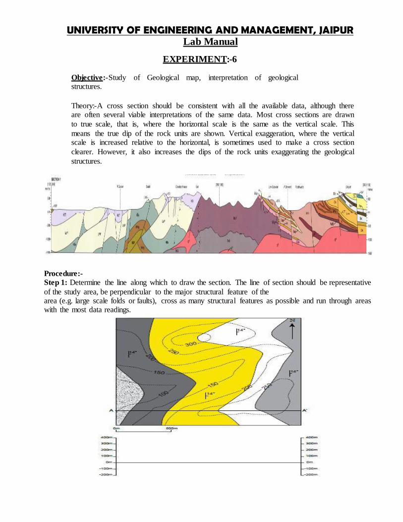
UNIVERSITY OF ENGINEERING AND MANAGEMENT JAIPUR Lab Manual
Step 2
Draw axes of an appropriate scale with theopographic values Unless there is a reason todo otherwise
draw a true-scale section
Step 3
Transfer the topographic information from the map to the section Project the height of each
topographic contour where it crosses the line of section on to the section and draw in
The topography
Step 4 Transfer the lithological boundaries faults etc onto the cross section in the same way
Step 5
Transfer bedding readings on to the section correcting for apparent dip if necessary (see figure)
Plot the readings at the height at which they occur so where a reading is
extrapolated from a greater or lesser height than the topography of the cross section plot it above or below the topography as appropriate
UNIVERSITY OF ENGINEERING AND MANAGEMENT JAIPUR Lab Manual
Step 6
Using the bedding readings as a guide draw in the lithological boundaries both above and
below the surface Geology extended above the topography is shown by dashed lines When drawing the section always consider what is geologically reasonable behavior for the
Layers eg sudden changes in a unitrsquos thickness or dip should be justifiable
UNIVERSITY OF ENGINEERING AND MANAGEMENT JAIPUR Lab Manual
Theory-If the Earthrsquos surface was flat if there was no topography then geological maps would be simple They would be a direct reflection of the underlying geology However topography interacts with the geology to produce more complex but predictable patterns
Horizontal and vertical strata
Horizontal and vertical strata are the most straight forward to interpret on a map Horizontal
outcrops will always follow the topographic contours (figure 2a) whilst vertical layers will always form straight lines (figure2b) Dipping strata
Dipping layers interact with the topography in predictable ways In valleys beds will appear to lsquoveersquo either up or down the valley in the direction of dip (figure 2c and 2d) This is because the
valley side acts as an approximate cross sectionndashnot always helpful on small scale maps but on
large scale maps and in the field this is a useful aid in interpretation
UNIVERSITY OF ENGINEERING AND MANAGEMENT JAIPUR Lab Manual
A Folding of rocks
a Layer cake relations
(1) Oldest on bottom youngest on top b Fold Types
(1) Anticlines-upfolded forms results in older rocks becoming enclosed within
younger strata
(2) synclines-downfolded forms results in younger rocks becoming enclosed within
older strata (3) Symmetrical folds- both limbs of the fold dipping at same angle away from fold axis
(4) Asymmetrical folds- both limbs of the fold not dipping at same angle away from fold axis
(5) Overturned folds- condition in which one limb of fold has been tilted beyond
vertical
(6) Plunging folds- axis of fold is tilted
(7) Domes- more or less circular equivalent of anticline oldest rocks exposed in center of dome
(8) Structural Basin- more or less circular equivalent of syncline youngest rocks exposed in center of dome (not to be confused with depositional basin)
c Outcrops Patterns Associated with Folded Rocks
(1) As rocks are folded and subsequently subjected to erosion regular patterns become
evident in relation to type of rock that outcrops and age of the rock that outcrops in
an area of folded strata In essence erosion exposes the interiors of the folds
(2) Non-plunging Folds- axis of fold is horizontal results in parallel bands of dipping strata
about the fold axis
(a) anticlines- oldest strata exposed along fold axis (b) synclines- youngest strata exposed along fold axis
(3)Plunging Folds-axis of fold is tilted results in alternating V-shaped bands of dipping strata oriented about the fold axis (a) anticlines- oldest strata exposed in the center of the V V points in direction of plunge of fold axis
(b) syncline- youngest strata exposed in the center of the V V points in opposite direction of plunge of fold axis
(4) Doubly Plunging Folds- fold axis is plunging in two opposite directions results in a
flattened oval pattern or a double V-shaped pattern ltltltgtgtgtgt
(a) anticlines- oldest strata exposed in center of flattened oval (b) synclines-youngest strata exposed in center of flattened oval
UNIVERSITY OF ENGINEERING AND MANAGEMENT JAIPUR Lab Manual
Faults on maps-Faults can occur at any angle with respect to bedding and so the
outcrop patterns produced are not unique to any one fault type Figure a and b show two potential outcrop patterns for a normal fault
Fold on maps - Figure shows the different outcrop patterns for folds The limbs of the
folds form a repeating pattern on either side of the axial plane For anticlines the oldest rocks are in core of the fold and the rocks get younger away from the axial trace (figure a) For synclines the youngest rocks are in the core and the rocks get older
away from the axial trace (figure b)
Plunging folds form the same repeating pattern as non-plunging folds except their limbs
converge around the axial traces The limbs of synclines open in the direction they plunge (figure c) whilst the limbs of anticlines close in the direction they plunge (figure d)
Viva Questions-
1 What do you mean by Geological Map 2 What are lithological boundaries
3 What do you mean by Scale 4 What is Fault 5 What is Fold
6 What do you mean by Syncline and anticyline
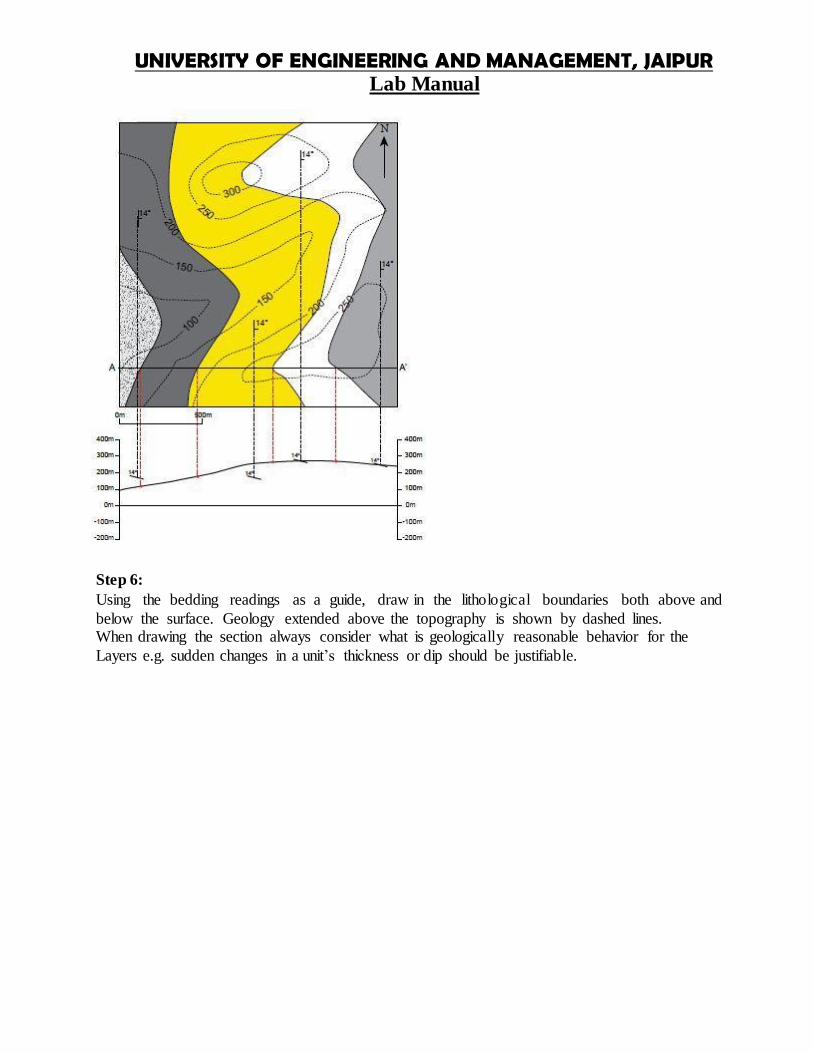
UNIVERSITY OF ENGINEERING AND MANAGEMENT JAIPUR Lab Manual
Faults on maps-Faults can occur at any angle with respect to bedding and so the
outcrop patterns produced are not unique to any one fault type Figure a and b show two potential outcrop patterns for a normal fault
Fold on maps - Figure shows the different outcrop patterns for folds The limbs of the
folds form a repeating pattern on either side of the axial plane For anticlines the oldest rocks are in core of the fold and the rocks get younger away from the axial trace (figure a) For synclines the youngest rocks are in the core and the rocks get older
away from the axial trace (figure b)
Plunging folds form the same repeating pattern as non-plunging folds except their limbs
converge around the axial traces The limbs of synclines open in the direction they plunge (figure c) whilst the limbs of anticlines close in the direction they plunge (figure d)
Viva Questions-
1 What do you mean by Geological Map 2 What are lithological boundaries
3 What do you mean by Scale 4 What is Fault 5 What is Fold
6 What do you mean by Syncline and anticyline
Top Related