![[Pierre Roberge] Corrosion Engineering Principles (Bookos.org)](https://static.fdocuments.us/doc/165x107/55cf98f5550346d0339aad12/pierre-roberge-corrosion-engineering-principles-bookosorg.jpg)


Languages
Pages
Legal


1
SCHOOL OF BIO & CHEMICAL ENGINEERING
DEPARTMENT OF CHEMICAL ENGINEERING
UNIT – I – Corrosion Engineering – SCH1614

2
INTRODUCTION
Corrosion is a natural process, which converts a refined metal to a more stable form, such as its
oxide, hydroxide, or sulfide. It is the gradual destruction of materials (usually metals) by chemical
and/or electrochemical reaction with their environment. Corrosion engineering is the field
dedicated to controlling and stopping corrosion. Corrosion can be defined as the degradation of
a material due to a reaction with its environment.
Degradation implies deterioration of physical properties of the material. This can be a weakening
of the material due to a loss of cross-sectional area, it can be the shattering of a metal due to
hydrogen embrittlement, or it can be the cracking of a polymer due to sunlight exposure.
Materials can be metals, polymers (plastics, rubbers, etc.), ceramics (concrete, brick, etc.) or
composites-mechanical mixtures of two or more materials with different properties. Because
metals are the most used type of structural materials most of this web site will be devoted to the
corrosion of metals.

3
Corrosion Engineering is the specialist discipline of applying scientific knowledge,
natural laws and physical resources in order to design and implement materials, structures, devices,
systems and procedures to manage the natural phenomenon known as corrosion. Generally related
to Metallurgy, Corrosion Engineering also relates to non-metallics including ceramics. Corrosion
Engineers often manage other not-strictly-corrosion processes including (but not restricted to)
cracking, brittle fracture, crazing, fretting, erosion and more.
THE CONSEQUENCES OF CORROSION / CORROSION DAMAGE
The consequences of corrosion are many and varied and the effects of these on the safe, reliable
and efficient operation of equipment or structures are often more serious than the simple loss of a
mass of metal. Failures of various kinds and the need for expensive replacements may occur even
though the amount of metal destroyed is quite small. Some of the major harmful effects of
corrosion can be summarised as follows:
1. Reduction of metal thickness leading to loss of mechanical strength and structural failure or
breakdown. When the metal is lost in localised zones so as to give a cracklike structure, very
considerable weakening may result from quite a small amount of metal loss.
2. Hazards or injuries to people arising from structural failure or breakdown (e.g. bridges, cars,
aircraft).
3. Loss of time in availability of profile-making industrial equipment.
4. Reduced value of goods due to deterioration of appearance.

4
5. Contamination of fluids in vessels and pipes (e.g. beer goes cloudy when small quantities of
heavy metals are released by corrosion).
6. Perforation of vessels and pipes allowing escape of their contents and possible harm to the
surroundings. For example a leaky domestic radiator can cause expensive damage to carpets and
decorations, while corrosive sea water may enter the boilers of a power station if the condenser
tubes perforate.
7. Loss of technically important surface properties of a metallic component. These could include
frictional and bearing properties, ease of fluid flow over a pipe surface, electrical conductivity of
contacts, surface reflectivity or heat transfer across a surface.
8. Mechanical damage to valves, pumps, etc, or blockage of pipes by solid corrosion products.
9. Added complexity and expense of equipment which needs to be designed to withstand a certain
amount of corrosion, and to allow corroded components to be conveniently replaced.
CORROSION RATE EXPRESSION
Corrosion rates have been expressed in a variety of ways such as percent weight loss, milligrams
per square centimeter per day and grams per square inch per hour.These do not express
corrosion resistance interms of penetration. From an engineering point of view, the rate of
penetration or the thinning of a structural piece can be used to predict the life of a given
component.
The expression mils per year (mpy) is the most desirable way of expressing corrosion rates.

5
Mpy = 534 W / DAT
Where
W is the weight loss in mg
D is the density of the Specimen in g/cm3 A is
the area of the specimen in Sq.In
T is the exposure time in Hr
CLASSIFICATION OF CORROSION
Corrosion can be classified in different ways, such as
Chemical and electrochemical
High temperature and low temperature
Wet corrosion and dry corrosion.
Dry corrosion occurs in the absence of aqueous environment, usually in the presence of gases and
vapours, mainly at high temperatures.
There are different forms of corrosion such as
1. Galvanic corrosion
2. Crevice corrosion
3. Pitting
4. Intergranular corrosion
5. Erosion corrosion
6. Stress corrosion

6
ELECTROCHEMICAL CORROSION REACTION
Electrochemical nature of corrosion can be understood by examining zinc dissolution in dilute
hydrochloric acid.
Zn + 2HCl = ZnCl2 + H2
Anodic reaction is Zn = Zn++ + 2e
with the reduction of 2H+ + 2e = H2 at cathodic areas on the surface of zinc metal. There are two
half reactions constituting the net cell reaction.
Environmental effects such as those of presence of oxygen and other oxidizers, changes in
flow rates (velocity), temperature, reactant concentrations and pH would influence rates of
anodic and cathodic reactions.

7
Rusting of iron consists of the formation of hydrated oxide, Fe(OH)3, FeO(OH), or even
Fe2O3.H2O. It is an electrochemical process which requires the presence
of water, oxygen and an electrolyte. In the absence of any one of these rusting does not occur to
any significant extent. In air, a relative humidity of over 50% provides the necessary amount of
water and at 80% or above corrosion of bare steel is worse.
When a droplet of water containing a little dissolved oxygen falls on an steel pipe, the solid iron
or Fe(s) under the droplet oxidizes:
Fe(s) --> Fe2+(aq) + 2e-
The electrons are quickly consumed by hydrogen ions from water (H2O) and dissolved
oxygen or O2(aq) at the edge of the droplet to produce water:

8
4e- + 4H+(aq) + O2(aq) --> 2H2O(l)
More acidic water increases corrosion. If the pH is very low the hydrogen ions will consume the
electrons anyway, making hydrogen gas instead of water:
2H+(aq) + 2e- --> H2(g)
Polarization
Mechanism in which the electrochemical reaction tends to be carried out Activation
Polarization
Activation polarization occurs when the electrochemical reaction proceeds through several
successive steps. The speed of the overall reaction is determined by the slowest step (known as
the rate-determining step) of the process. For example, in a hydrogen reduction reaction, the
reaction may proceed as follows:
1. Hydrogen ions are absorbed from the solution onto the anode surface.
2. Electron transfer occurs from the anode to the hydrogen ions to form hydrogen.
3. The hydrogen atoms form hydrogen gas molecules.
4. Hydrogen gas bubbles are formed.
Concentration Polarization
Concentration polarization of an electrode is the result of formation of a diffusion layer adjacent
to the surface of the electrode where there is a gradient of ion concentration. Diffusion of the
ions through the layers controls the electrochemical reaction and is important for processes such
as electroplating and corrosion.
Concentration polarization may be reduced by increasing agitation or raising the temperature of
the electrolyte.

9
Passivity
Passivity occurs when an oxide layer forms a continuous film on a metal surface that prevents
further oxidation (corrosion). Metals that are normally subject to corrosion will sometimes
exhibit passivity.
Passivity is caused by the buildup of a layer of metal oxide on the surface of a metal. In order to
provide passivity, this oxide layer must be both stable and tenacious. It is formed by corrosion
when the products of corrosion are insoluble in the particular environment to which the metal is
exposed. The metal oxide acts as a barrier by separating the metal surface from its environment
and prevents corrosion until the reactants diffuse through the oxide film. This diffusion can take a
very long time, or may never occur at all.
Metals such as zirconium, chromium, aluminum and stainless steel form oxide films when
exposed to the atmosphere or to water. In some cases, the film is so thin that it's invisible to
the naked eye. Nevertheless, it is still very effective in giving these metals passivity.
Passivation refers to a material becoming "passive," that is, less affected or corroded by the
environment of future use. Passivation involves creation of an outer layer of shield material that
is applied as a microcoating, created by chemical reaction with the base material, or allowed to
build from spontaneous oxidation in the air. As a technique, passivation is the use of a light
coat of a protective material, such as metal oxide, to create a shell against corrosion. Passivation
can occur only in certain conditions, and is used in microelectronics to enhance silicon.
Environmental effects
10
1. Effect of oxygen and oxidizers
2. Effect of velocity
3. Effect of temperature
4. Effect of corrosive concentration
5. Effect of galvanic coupling
Effect of oxygen and oxidizers
For metals that exhibit active-passive transition, passivity is achieved only if a sufficient
quantity of oxidizer is added to the medium. Increasing corrosion rate with increasing
oxidizer concentrations is characteristic of monel and copper in acid solutions containing
oxygen. Both of these materials do not passivate.
An increase in corrosion rate, followed by a rapid decrease and then a corrosion rate that is
independent of oxidizer concentration is characteristic of such active- passive metals and alloys.
By knowing the basic characteristics of a metal or alloy and the environment to which it is
exposed it is possible to predict the effect of oxidizer additions.
Effects of Velocity
The effect of velocity on corrosion rate depends on the characteristics of the metal and the
environment to which it is exposed. For corrosion processes that are controlled by activation
polarization, agitation and velocity have no effect on the corrosion rate. If the corrosion process
is under cathodic diffusion control, the agitation increases the corrosion rate.

Effect of Temperature
Temperature increases the rate of almost all chemical reactions.A very rapid or
exponential increase in corrosion rate occurs with increasing temperature.
Effects of corrosive concentration
Many materials that exhibit passivity effects are only negligibly affected by wide
changes in corrosive concentration.
Effect of galvanic coupling
In many practical applications, the contact of dissimilar materials is unavoidable. In
complex process streams and piping arrangements, different metals and alloys are
frequently in contact with each other and the corrosive medium. Consider a piece of zinc
in a hydrochloric acid solution and contacted to a noble metal such as platinum. Since
platinum is inert in this medium, it tends to increase the surface at which hydrogen
evolution can occur. Further, hydrogen evolution occurs much more readily on the
surface of platinum than on zinc.
SCHOOL OF BIO & CHEMICAL ENGINEERING

DEPARTMENT OF CHEMICAL ENGINEERING
TYPES OF CORROSION
Corrosion is the primary means by which metals deteriorate. Most metals corrode on contact with
water (and moisture in the air), acids, bases, salts, oils, aggressive metal polishes, and other solid
and liquid chemicals. Metals will also corrode when exposed to gaseous materials like acid vapors,
UNIT – II-Corrosion Engineering-SCH1614

formaldehyde gas, ammonia gas, and sulfur containing gases. Corrosion specifically refers to any
process involving the deterioration or degradation of metal components. The best known case is
that of the rusting of steel. Corrosion processes are usually electrochemical in nature, having the
essential features of a battery.
When metal atoms are exposed to an environment containing water molecules they can give up
electrons, becoming themselves positively charged ions, provided an electrical circuit can be
completed. This effect can be concentrated locally to form a pit or, sometimes a crack, or it can
extend across a wide area to produce general wastage. Localized corrosion that leads to pitting
may provide sites for fatigue initiation and, additionally, corrosive agents like seawater may lead
to greatly enhanced growth of the fatigue crack. Pitting corrosion also occurs much faster in areas
where microstructural changes have occurred due to welding operations.
The corrosion process (anodic reaction) of the metal dissolving as ions generates some electrons,
as shown in the simple model on the left, that are consumed by a secondary process (cathodic
reaction). These two processes have to balance their charges. The sites hosting these two
processes can be located close to each other on the metal's surface, or far apart depending on the
circumstances. This simple observation has a major impact in many aspects of corrosion
prevention and control, for designing new corrosion monitoring techniques to avoiding the most
insidious or localized forms of corrosion.

Factors influencing corrosion
1. Based on the nature of the metal
Position in galvanic series
Overvoltage
Relative areas of the anodic and cathodic parts Purity
of the metal
Physical state of the metal Nature of
the surface film Passive character of
the metal Solubility of corrosion
products Volatility of corrosion
products
2. Nature of the corroding environment
Temperature
Humidity of air
Presence of impurities in atmosphere Influence of
Ph
Nature of ions present
Conductance of the corroding medium Formation
of oxygen concentration cell Flow velocity of
process stream Polarization of electrodes

General Attack Corrosion
Also known as uniform attack corrosion, general attack corrosion is the most common type of
corrosion and is caused by a chemical or electrochemical reaction that results in the deterioration
of the entire exposed surface of a metal. Ultimately, the metal deteriorates to the point of failure.
General attack corrosion accounts for the greatest amount of metal destruction by corrosion, but is
considered as a safe form of corrosion, due to the fact that it is predictable, manageable and often
preventable.
Localized Corrosion
Unlike general attack corrosion, localized corrosion specifically targets one area of the metal
structure. Localized corrosion is classified as one of three types:
Pitting: Pitting results when a small hole, or cavity, forms in the metal, usually as a result of de-
passivation of a small area. This area becomes anodic, while part of the remaining metal becomes
cathodic, producing a localized galvanic reaction. The deterioration of this small area penetrates
the metal and can lead to failure. This form of corrosion is often difficult to detect due to the fact
that it is usually relatively small and may be covered and hidden by corrosion-produced
compounds.Pitting Corrosion occurs under certain conditions, which leads to accelerated corrosion
in certain areas rather than uniform corrosion throughout the piece. Such conditions include low
concentrations of oxygen or high concentrations of chlorides (anions) that interfere with the
alloy’s ability to reform a passivating film. In the worst cases, most of the surface remains
protected, but tiny fluctuations degrade the film in a few critical areas. Corrosion at these points
is amplified and can cause pits.

Crevice corrosion: Similar to pitting, crevice corrosion occurs at a specific location. This
type of corrosion is often associated with a stagnant micro- environment, like those found
under gaskets and washers and clamps. Acidic conditions, or a depletion of oxygen in a
crevice can lead to crevice corrosion.
Filiform corrosion: Occurring under painted or plated surfaces when water breaches the
coating, filiform corrosion begins at small defects in the coating and spreads to cause
structural weakness.
Galvanic Corrosion
Galvanic corrosion, or dissimiliar metal corrosion, occurs when two different metals are located
together in a corrosive electrolyte. A galvanic couple forms between the two metals, where one
metal becomes the anode and the other the cathode. The anode, or sacrificial metal, corrodes
and deteriorates faster than it would alone, while the cathode deteriorates more slowly than it would
otherwise.
Three conditions must exist for galvanic corrosion to occur:
Electrochemically dissimilar metals must be present
The metals must be in electrical contact, and
The metals must be exposed to an electrolyte
Here is a brief overview of some common types of corrosion:
Galvanic corrosion is the most common and impactful form of corrosion. It occurs when two
dissimilar (different) metals are in contact in the presence of an electrolyte. In a galvanic cell
(bimetallic couple), the more active metal (anode)
corrodes and the more noble metal (cathode) is protected. There are a number of factors that affect
the galvanic corrosion including types of metals, relative size of anode, and environment
(temperature, humidity, salinity, etc.)
Galvanic corrosion is extraordinarily common, and occurs when two metals with different
electrochemical charges are linked via a conductive path. Corrosion occurs when metal ions move
from the anodized metal to the cathodic metal. In this case, a corrosion resistant coating would
be applied to prevent either the transfer of ions or the condition that causes it. Galvanic corrosion
can also occur when one impure metal is present. If a metal contains a combination of alloys that
possess different charges, one of the metals can become corroded. The anodized metal is the
weaker, less resistant one, and loses ions to the stronger, positively charged cathodic metal.
Without exposure to an electrical current, the metal corrodes uniformly; this is then known as
general corrosion.
Environmental Cracking
Environmental cracking is a corrosion process that can result from a combination of
environmental conditions affecting the metal. Chemical, temperature and stress- related conditions
can result in the following types of environmental corrosion:
Stress Corrosion Cracking (SCC)
Corrosion fatigue
Hydrogen-induced cracking
Liquid metal embrittlement

Microbial corrosion, commonly referred to as microbiologically influenced corrosion (MIC)
is caused by microorganisms. It applies to both metallic and non-metallic materials with or
without oxygen. When oxygen is absent, sulfate-reducing bacteria are active and produce
hydrogen sulfide causing sulfide stress cracking. When oxygen is present, some bacteria
may directly oxidize iron to iron oxides and hydroxides. Concentration cells can form in
the deposits of corrosion products, leading to localized corrosion.
Stress-corrosion cracking (SCC) can seriously damage a component beyond the point of
repair. When subjected to extreme tensile stress, a metal component can experience SCC
along the grain boundary—cracks form, which are then targets for further corrosion. There
are multiple causes of SCC, including stress caused by cold work, welding, and thermal
treatment. These factors, combined with exposure to an environment that often increases
and intensifies stress-cracking, can mean a part goes from suffering minor stress-corrosion
to experiencing failure or irreparable damage.
Crevice Corrosion
Crevice corrosion is a localized attack on a metal adjacent to the crevice between two joining
surfaces (two metals or metal-nonmetal crevices). The corrosion is generally confined to one
localized area to one metal. This type of corrosion can be initiated by concentration gradients
(due to ions or oxygen). Accumulation of chlorides inside crevice will aggravate damage.
Various factors influence crevice corrosion, such as. Materials: alloy composition, metallographic
structure. Environmental conditions such as pH, oxygen concentration, halide concentrations,

temperature. Geometrical features of crevices, surface roughness. Metal to metal or metal to
nonmetal type. Filiform corrosion is a special type of crevice corrosion
Erosion Corrosion
Erosion corrosion is the deterioration of metals and alloys due to relative movement between
surfaces and corrosive fluids. Depending on the rate of this movement, abrasion takes place. This
type of corrosion is characterized by grooves and surface patterns having directionality. Typical
examples are Stainless alloy pump impeller, Condenser tube walls. All equipment types exposed
to moving fluids are prone to erosion corrosion. Many failures can be attributed to impingement
(impingement attack). Erosion corrosion due to high velocity impingement occurs in steam
condenser tubes, slide valves in petroleum refinery at high temperature, inlet pipes, cyclones and
steam turbine blades. Cavitation damage can be classified as a special form of erosion corrosion.
This is usually caused by formation and collapse of vapour bubbles in liquids closer to a metal
surface. Typical examples include ship‟s propellers, pump impellers and hydraulic turbines.
Surface damage similar to that of pitting can occur and both corrosion and mechanical factors
are involved. Corrosion occurring at contact regions between materials under load subjected to
slip and vibration can be termed Fretting. Such friction oxidation can occur in engine and
automotive parts. Fretting is known to occur at bolted tie plates on rails.
Waterline Corrosion
When water is stored in a steel tank, it is generally found that the maximum amount of corrosion
takes place along a line just beneath the level of the water meniscus. The area above the waterline
acts as cathodic and is completely unaffected by corrosion.

Hydrogen Damage
It is a general term which refers to the mechanical damage of a metal caused by the presence of or
interaction with hydrogen. Hydrogen damage may be classified into four distinct types
1. Hydrogen blistering
2. Hydrogen embrittlement
3. Decarburization
4. Hydrogen attack

SCHOOL OF BIO&CHEMICAL ENGINEERING
DEPARTMENT OF CHEMICAL ENGINEERING
CORROSION PROTECTION MEASURES
UNIT – III – Corrosion Engineering – SCH1616

3.0 Causes of Corrosion
All materials or products, plants, constructions, and buildings made of such materials are
subject to physical wear during use.
The technical and economic mastering of physical wear is difficult, since several causes are
intertwined and mutually influence each other. The interaction with certain media of the
environment results in undesired reactions of the materials that trigger corrosion, weathering,
decaying, embrittlement, and fouling.
While mechanical reactions lead to wear, chemical and electrochemical reactions cause
corrosion. Such processes emanate from the materials’ surfaces and lead to modifications of the
material properties or to their destruction. According to DIN EN ISO 8044, corrosion is defined
as:
“ Physical interaction between a metal and its environment which results in changes of the
metal ’ s properties and which may lead to significant functional impairment of the metal, the
environment or the technical system of which they form a part. ”
3.1 Corrosion Protection
All methods, measures, and procedures aimed at the avoidance of corrosion damages are called
corrosion protection. Modifications of a corrosion system in so far as corrosion damages are minimized.
Methods, measures, and procedures of corrosion
protection

3.1.1 Active Procedures
Active corrosion protection helps reduce or avoid corrosion by means of manipulation of the
corrosion process, corrosion protection - related material selection, project engineering, design and
manufacturing. But it is also a significant precondition for the effectiveness of passive corrosion -
protection procedures. The following aspects are surveyed in this respect:
Design - Engineering Requirements The basic design - engineering requirements of the corrosion
- protection - related design of steel structures are defined in the DIN
EN ISO 12944 - 3:
• corrosion protection of steel structures by protective paint systems;
• basic rules for protective coating;
• EN ISO 14713;
• protection of iron and steel structures against corrosion – zinc and aluminum coatings. In the
figurative sense, they also apply to other products, unless these contain precise requirements
determined in the respective DIN. In his engineering work, the design engineer has to consider the
corrosive stress triggered by the corrosion
types and phenomena. He has to depict a design engineering solution that is expected to provide
an efficient protection period with optimal quality.
Here, essential aspects are:
• Materials used
Knowledge of their properties and corrosion behavior are required.
• Surface design
Preference to components with small corrosion - prone surfaces.
• Profiles used
Preference to profiles forming the smallest number of edges. The angle profile ranks before the U
- profile, the U - profile before the I - profile.
Component arrangement
Components and structures have to be arranged in a way to prevent or minimize the impact of
aggressive media and to ensure an unimpeded circulation of air.
• Component joining
The joining of components preferably requires smooth, closed surfaces. Fasteners require the
same corrosion protection as the constructions, or an equivalent one with regard to the protection period.
• Manufacturing requirements
The application of a passive corrosion - protection procedure entails the consideration of
manufacturing criteria already in the design phase.
The determination of a corrosion - protection procedure results, inter alia , in the demand for a
design compatible with coating, hot - dip galvanizing, sputtering, enameling and galvanizing.
• Maintenance - related requirements The corrosion protection design has to allow for the
possibility of efficient maintenance measures. Since the service life of components, constructions,
products, plants and buildings differs from the protection period of the corrosion protection,
repeated protection measures are usually required.

3.1.2 Passive Procedures
In passive corrosion protection, corrosion is prevented or at least decelerated through the
isolation of the metal material from the corrosive agent by the applied protective layers. The
technical preconditions of a corrosion layer are:
• the protective layer has to be pore - free;
• it must adhere firmly to the base material;
• it must be resistant to external mechanical stress;
• it must possess a certain ductility; and
• it must be corrosion resistant.
Overview of passive corrosion - protection procedures

3.2 Anodisation
Anodising is a process for producing decorative and protective films on articles made of aluminium
and its alloys. The article is made the anode of an electolytic cell with aqueous sulfuric acid as
electrolyte where the following overall oxidation reaction occurs.
2Al + 3H2O → Al2O3 + 6H+ + 6e-
A dense even layer of oxide about 0.08 μm thick is formed rapidly, followed much more slowly
with a more porous layer up to 25μm thick.
Before anodising the surface of the article must be horoughly cleaned, normally using a detergent
based process, and etched with a solution of sodium hydroxide.
After anodising the surface may be coloured with a dye or by an electrolytic method using
appropriate metal cations, and then sealed by placing in boiling water, the pores in the oxide layer
being closed off.
Anodizing successfully combines science with nature to create one of the world's best metal
finishes. It is an electrochemical process that thickens and toughens the naturally occurring
protective oxide. The resulting finish, depending on the process, is the second hardest substance
known to man, second only to the diamond. The anodic coating is part of the metal, but has a
porous structure which allows secondary infusions, (i.e. organic and inorganic coloring, lubricity
aids, etc.)
Anodizing Definitions and Methods
While the chemical anodizing process remains the same for all applications, the mechanical
methods vary according to the two physical types and shapes of metals used:
Batch Anodizing - Involves racking parts and immersing them in a series of treatment
tanks. Extrusions, sheets or bent metal parts, castings, cookware, cosmetic cases, flashlight
bodies, and machined aluminum parts are just a few of the items that are batch anodized.
Continuous Coil Anodizing - Involves continuous unwinding of pre-rolled coils through
a series of anodizing, etching and cleaning tanks, and then rewinding for shipment and
fabrication. This method is used for high volume sheet, foil and less severely formed
products such as lighting fixtures, reflectors, louvers, spacer bars for insulated glass, and
continuous roofing systems.
Appearance options and quality are improved through the use of dyes and special pretreatment
procedures. This makes the aluminum look like pewter, stainless steel, copper, brushed bronze or

polished brass and can also be colored with brilliant blues, greens, reds, and many varieties of
metallic gold and silver.
The unique dielectric properties of an anodized finish offer many opportunities for electrical
applications.
On the Theory of Corrosion
In order that rust should be formed iron must go into solution and hydrogen must be given off in the
presence of oxygen or certain oxidizing agents. This presumes electrolytic action, as every iron ion that
appears at a certain spot demands the disappearance of a hydrogen ion at another, with a consequent
formation of gaseous hydrogen. The gaseous hydrogen is rarely visible in the process of rusting, owing to
the rather high solubility and great diffusive power of this element. Substances which increase the
concentration of hydrogen ions, such as acids and acid salts, stimulate corrosion, while substances which
increase the concentration of hydroxyl ions inhibit it. Chromic acid and its salts inhibit corrosion by
producing a polarizing or dampening effect which prevents the solution of iron and the separation of
hydrogen.
Electrolytic Theory of Corrosion of Iron
From the standpoint of the electrolytic theory, the explanation of the corrosion of iron is not complicated,
and so far has been found in accordance with all the facts. Briefly stated, the explanation is as follows:
Iron has a certain solution tension, even when the iron is chemically pure and the solvent pure water. The
solution tension is modified by impurities or additional substances contained in the metal and in the
solvent. The effect of the slightest segregation in the metal, or even unequal stresses and strains in the
surface, will throw the surface out of equilibrium, and the solution tension will be greater at some points
than at others.
The driving force that causes metals to corrode is a natural consequence of their temporary existence in
metallic form. In order to produce metals starting from naturally occurring minerals and ores, it is
necessary to provide a certain amount of energy. It is therefore only natural that when these metals are
exposed to their environments they would revert back to the original state in which they were found. A
typical cycle is illustrated by iron. The primary corrosion product of iron, for example, is Fe(OH)2 (or
more likely FeO·nH2 O), but the action of oxygen and water can yield other products having different
colors: • Fe2 O3 ·H2 O or hydrous ferrous oxide, sometimes written as Fe(OH)3 , is the principal
component of red-brown rust. It can form a mineral called hematite, the most common iron ore. • Fe3 O4
·H2 O or hydrated magnetite, also called ferrous ferrite (Fe2 O3 ·FeO), is most often green but can be
deep blue in the presence of organic complexants. • Fe3 O4 or magnetite is black. The energy required to
convert iron ore to metallic iron is returned when the iron corrodes to form the original compound. Table
2.1 describes the results of x-ray diffraction of products found on specimens exposed to real
environments where it can be seen that the metals often revert to naturally occurring mineral forms
during the corrosion process [1]. The amount of energy required and stored in a metal or that is freed by
its corrosion varies from metal to metal. It is relatively high for metals such as magnesium, aluminum,
and iron, and relatively low for metals such as copper, silver, and gold. Table 2.2 lists a few metals in
order of diminishing amounts of energy required to convert them from their oxides to metal

The surface of the aluminum itself is toughened and hardened to a degree unmatched by any other
process or material. The coating is 30 percent thicker than the metal it replaces, since the volume
of oxide produced is greater than that of the metal
replaced.
The resulting anodic coating is porous, allowing relatively easy coloring and sealing.
Hard Anodizing is a term used to describe the production of anodic coatings with film hardness or
abrasion as their primary characteristic. They are usually thick by normal anodizing standards
(greater than 25 microns) and they are produced using special anodizing conditions (very low
temperature, high current density, special electrolytes). They find application in the engineering
industry for components which require a very wear resistant surface such as piston, cylinders and
hydraulic gear. They are often left unsealed, but may be impregnated with materials such as waxes
or silicone fluids to give particular surface properties.
Batch and Coil Anodizing
Batch and coil anodizing are accomplished in five carefully controlled, calibrated, quality-tested stages:
Cleaning. Alkaline and/or acid cleaners remove grease, and surface dirt.
Pre-Treatment
Etching. An appealing matte surface finish is created with hot solutions of sodium hydroxide to
remove minor surface imperfections. A thin layer of aluminum is removed to create a matte or dull
finish.
Brightening. A near mirror finish is created with a concentrated mixture of phosphoric and nitric
acids which chemically smooths the aluminum's surface.
Anodizing. The anodic film is built and combined with the metal by passing an electrical
current through an acid electrolyte bath in which the aluminum is immersed. The coating
thickness and surface characteristics are tightly controlled to meet end product
specifications.
Coloring. Coloring is achieved in one of four ways:
Electrolytic Coloring (The two-step method) - After anodizing, the metal is immersed in a bath
Anodizing Line containing an inorganic metal salt. Current is applied which deposits the metal salt
in the base of the pores. The resulting color is dependent on the metal used and the processing
conditions (the range of colors can be expanded by over dyeing the organic dyes). Electrolytic colors
can be specified from any AAC member. Commonly used metals include tin, cobalt, nickel, and
copper. This process offers color versatility and the most technically advanced coloring quality.
Integral Coloring - This so-called one-step process combines anodizing and coloring to
simultaneously form and color the oxide cell wall in bronze and black shades while more abrasive

resistant than conventional anodizing. It is the most expensive process since it requires
corrosion prevention.
there are a variety of measures you can take to minimize corrosion. Here we’ll highlight four of these
methods based on cost and effectiveness.
BARRIER COATINGS
One of the easiest and cheapest ways to prevent corrosion is to use barrier coatings like paint, plastic, or
powder. Powders, including epoxy, nylon, and urethane, are heated to the metal surface to create a thin
film. Plastic and waxes are often sprayed onto metal surfaces. Paint acts as a coating to protect the metal
surface from the electrochemical charge that comes from corrosive compounds. Today’s paint
systems are actually a combination of different paint layers that serve different functions. The primer coat
acts as an inhibitor, the intermediate coat adds to the paint’s overall thickness, and the finish coat
provides resistance to environmental factors.
The biggest drawback with coatings is that they often need to be stripped and reapplied. Coatings that
aren’t applied properly can quickly fail and lead to increased levels of corrosion. Coatings may also
contain volatile organic compounds, which can make them vulnerable to corrosion.
HOT-DIP GALVANIZATION
This corrosion prevention method involves dipping steel into molten zinc. The iron in the steel reacts
with the zinc to create a tightly bonded alloy coating which serves as protection. The process has been
around for more than 250 years and has been used for corrosion protection of things like artistic
sculptures and playground equipment. Compared to other corrosion prevention methods, galvanization is
known for lower initial costs, sustainability, and versatility.
Unfortunately, galvanization can’t be done on-site, meaning companies have to pull equipment out of
work to be treated. Some equipment may simply be too large for the process, forcing companies to
abandon the idea altogether. In addition, if the process isn’t done properly, the zinc can chip or peel. And
high exposure to environmental elements can speed up the process of zinc wear, leading to increased
maintenance check-ups. Lastly, the zinc fumes that release from the galvanizing process are toxic.
ALLOYED STEEL (STAINLESS)
Alloyed steel is one of the most effective corrosion prevention methods around, combining the properties
of various metals to provide added strength and resistance to the resulting product. Corrosion-resistant
nickel, for example, combined with oxidation-resistant chromium results in an alloy that can be used in
oxidized and reduced chemical environments. Different alloys provide resistance to different conditions,
giving companies greater flexibility.
Despite its effectiveness, alloyed steel is very expensive. Companies with limited financial resources will
likely have to turn to other methods. Monitoring surface conditions are critical, as cracks or scratches can
result in an increase in corrosion. Companies also need to make sure the agents used in maintenance
don’t include corrosion properties.

CATHODIC PROTECTION
Cathodic protection protects against galvanic corrosion, which occurs when two different metals are put
together and exposed to a corrosive electrolyte. To prevent this, the active sites on the metal surface need
to be converted to passive sites by providing electrons from another source, typically with galvanic
anodes attached on or near the surface. Metals used for anodes include aluminum, magnesium, or zinc.
While cathodic protection is highly effective, anodes need to be checked often which can drive up costs
of maintenance. They also increase the weight on the attached structure and aren’t always effective in
high-resistivity environments. Finally, anodes lead to increased water flow on ships and other underwater
equipment.
EONCOAT
Choosing the right corrosion prevention for your equipment isn’t easy. Each of the above methods has its
pros and cons, which is where EonCoat comes in. Compared to the cost-effective, maintenance-free, and
on-site ability of EonCoat, other methods can’t compete. EonCoat uses no toxic chemicals and is
environmentally friendly. Our 30-year warranty ensures your equipment stays protected for longer.
We’ve made it a point to provide the best corrosion protection method available to help companies like
yours moving along with as little hassle as possible. There’s no reason not to take advantage of
EonCoat’s power today.
There are several cost effective ways to prevent corrosion including:
Use non-corrosive metals, such as stainless steel or aluminium
Make sure the metal surface stays clean and dry
Use drying agents
Use a coating or barrier product such as grease, oil, paint or carbon fibre coating
Lay a layer of backfill, for example limestone, with underground piping
Use a sacrificial anode to provide a cathodic protection system

Organic Dyeing - The organic dyeing process produces a wide variety of colors. These dyes offer
vibrant colors with intensities that cannot be matched by any other paint system in the market.
They can also provide excellent weather-fastness and light-fastness. Many structures built with these
finishes have lasted more than 20 years. The color range can be broadened by over-dyeing the
electrolytic colors with the organic dyes for a wider variety of colors and shades. This method is
relatively inexpensive and involves the least amount of initial capital of any other coloring process.
Interference Coloring - An additional coloring procedure, recently in production, involves
modification of the pore structure produced in sulfuric acid. Pore enlargement occurs at the base of
the pore. Metal deposition at this location produces light-fast colors ranging from blue, green and
yellow to red. The colors are caused by optical-interference effects, rather than by light scattering
as with the basic electrolytic coloring process.
Sealing. This process closes the pores in the anodic film, giving a surface resistant to
staining, abrasion, crazing and color degradation.
Quality control. Throughout the entire anodizing process, AAC members monitor the process and
quality of the product. The application of electrical power and color is preprogrammed and verified
on all batches and coils.
This quality control ensures uniformity to end product specifications for film thickness, density,
abrasion resistance, corrosion resistance, color uniformity, fade resistance, reflectivity, image
clarity, insulative properties, adhesion and sealing.
In many cases, AAC members use Statistical Process Control (SPC) methods to meet rigorous
quality assurance standards.
3.3 Enameling
Vitreous enamel is glass bonded by fusion to a metal surface. The most common glass is a fusion
of silica, soda, lime, and a small amount of borax. Though normally transparent, various amounts
of opacity can be produced by adding or growing crystals within the glass structure. A wide range
of colors are produced by incorporating certain elements, mostly transition metals. The physical
properties of glass can be controlled to permit bonding to most metals, for example: gold,
platinum, silver, copper, steel, cast iron, aluminum and titanium. The word "Enamel" refers to
the glass material, as well as to the finished product.
Enamel (glass) is crushed to a powder somewhat finer than granulated sugar and somewhat coarser
than flour. This powder is applied, by one of several methods, to the metal surface. Next, the
article is heated to 1000-1600°F, either in a preheated furnace, or with a hand-held torch. After

few minutes, the article is removed and allowed to cool to room temperature. Subsequent coats,
normally different colors, are applied. Sometimes 10-20 firings are required to bring about the
desired results.
3.4 What is Rubber Lining?
Rubber lining is the skilled application of unvulcanised rubber sheet to prepared metal surfaces.
The lined items are then vulcanised in a steam autoclave, fully bonding the rubber to the metal
surface creating a durable and resilient protective rubber coating.
The rubber coating can be from 2mm to 50mm thick depending on the application, and can be
bonded to mild steel, stainless steel, cast iron and aluminum.
Benefits
The principal benefits of rubber lining are its excellent resistance to corrosive and abrasive
chemicals and materials, e.g. acids, alkalis, salt water, slurries, sand, shotblast media, crushed rock
etc. In addition rubber linings provide other benefits including noise and vibration reduction,
electrical and thermal insulation and product protection.
In general, a surface which requires protective coating from wear, corrosion and rust, a coat of
rubber lining is applied. The lining of rubber is mostly applied to inner surfaces of the container.
The surface to be rubber lined has to be cleaned by sandblasting to white metal. When the old
lining to be replaced, surface decontamination may be required prior to sandblasting. Then the
surface will be coated with adhesive with the help of a brush or roller. The adhesive. coating
consists generally of two to three coats of different adhesives. Then rubber is applied by cutting
the rubber sheet to fit to the shape of the surface to be lined and adhering it to the surface. Care is
taken to remove any air trapped between surface and the rubber sheet. A special care to be taken
for this. For pipe linings, a specialized methods are followed. Then the rubber along with the
surface to be cured or in other words vulcanized in autoclave or under cover of steam or hot air.
The final inspection consists of spark testing the lined surface by a high voltage which detects any
pin holes in the lining and if it is found they has to be repaired and retested before putting the
surface in required service.
3.4 Glass Lining
Glass Lining Properties Glass-lined steel equipment features unique characteristics that make it
mandatory for use in processes when service conditions are particularly difficult. This is the case
for applications involving products that exceed the resistance limitations for corrosion, abrasion,
mechanical and thermal shocks. Chemical and pharmaceutical companies are continually
extending the limits of their processes in order to increase productivity or succeed in new
developments, calling for higher temperatures, lower temperatures, higher pressures, and higher
concentrations. The capability to extend standard limitations is possible only if the equipment in
use can withstand these progressive operating requirements.
GLASS-LINED STEEL BENEFITS Glass-lined steel’s composite metal/glass material of
construction provides the best of both worlds of each of the primary components. The external
steel construction.
Earlier was known, it would be possible to convert this current to an equivalent mass loss or
corrosion penetration rate with a very useful relation discovered by Michael Faraday, a nineteenth
century pioneer in electrochemistry. Faraday’s empirical laws of electrolysis relate the current of
an electrochemical reaction to the number of moles of the element being reacted and the number
of moles of electrons involved. Supposing that the charge required for such reaction was one
electron per molecule, as is the case for the plating or the corrosion attack of silver described
respectively.
Ag e Ag(s) + − + → Ag(s) Ag e → + − + According to Faraday’s law, the reaction with 1 mol of
silver would require 1 mol of electrons, or 1 Avogadro’s number of electrons (6.022 × 10²³). The
charge carried by 1 mol of electrons is known as 1 faraday (F).
The faraday is related to other electrical units through the electronic charge; the electronic charge
is 1.6 × 10⁻¹⁹ coulomb (C). Multiplying the electronic charge by the Avogadro number means
that 1 F equals 96,485 C/(mol of electrons). Combining Faraday’s principles with specific
electrochemical reactions of known stoichiometry leads that relates the charge Q to chemical
descriptors N and where N is the number of moles and ∆N the change in that amount n is the
number of electrons per molecule of the species being reacted The charge Q can be defined in
terms of electric current where I is the total current in amperes (A) t is the duration of the
electrochemical process in seconds (s)
provides strength while the internal glass lining gives nearly universal corrosion protection and a
smooth non-contaminating surface. Additionally, companies choose to use glass-lined equipment
for the various other benefits it offers, including: • Anti-Stick - Many substances will not stick to
glass, but will stick to metal. • Purity - Glass has high quality standards for food and drug
applications. • Flexibility – Glass can handle a diverse range of chemical conditions. Drastic
changes in process involve no added investment for new equipment. • Ease of Cleaning – Fire
polish lends itself to quick, easy cleaning and sterilization. • Absence of Catalytic Effect –
Eliminates the possibility of catalytic effect. • Economy – Glass-lined steel equipment is the most
corrosive resistant material. The cost is comparable to stainless and most alloys.
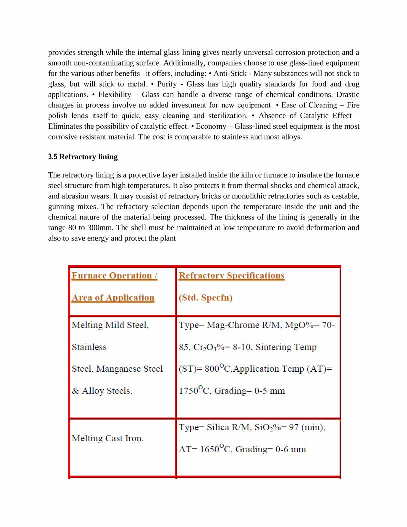
3.5 Refractory lining
The refractory lining is a protective layer installed inside the kiln or furnace to insulate the furnace
steel structure from high temperatures. It also protects it from thermal shocks and chemical attack,
and abrasion wears. It may consist of refractory bricks or monolithic refractories such as castable,
gunning mixes. The refractory selection depends upon the temperature inside the unit and the
chemical nature of the material being processed. The thickness of the lining is generally in the
range 80 to 300mm. The shell must be maintained at low temperature to avoid deformation and
also to save energy and protect the plant

3.6 Factors Affecting Corrosion
1. Nature of the Metal 2. Nature of the environment.
3.6.1 Nature of Metal
(i) Position in Galvanic Series:
If two metals are present in electrolyte, the metal with less reduction potential
undergoes corrosion.
- Greater the difference faster the corrosion.
(ii) Over Voltage:
Due to high evolution of hydrogen, the rate is slow.
(iii) Area and Distance:
When anodic metal area is smaller than cathodic area, rate of corrosion at
anode is higher because of demand of electron by cathodic area.
(iv) Physical and Mechanical properties of Metal:
Pure metals are more corrosion resistant.
Smaller grain size metal have high solubility and corrosion.
Uniform distribution of stress on metal reduces rate of corrosion.

Passive metals shows higher corrosion resistance because of formation of protective
oxide film on their surface.
Polycrystalline forms are more sensitive.
3.6.2 Nature of Environment
Temperature: directly proportional
Humidity: faster in humid conditions
pH : If less than 7 rate is high. Al, Zn, Sn, Pb, and Fe are affected by both acid and bases.
Impurities and Suspended Particles: When these will get dissolved in moisture, provides electrolyte for conductivity and hence corrosion increases.
3.7 Corrosion Control:
3.7.1 Selection of metal and alloy:
Using pure and noble metals
Practically not possible because of low strength of pure metal
Use of metal alloys which are homogeneous
3.7.2 Proper design of metal:
Minimal contact with medium
Prevention from moisture
Adequate ventilation and drainage
Welding
Avoid cervices b/w adjacent parts
Bend should be smooth
Bimetallic contacts should be avoided
Paint cathodic portion
Prevent uneven stress
Cathodic Protection:
Force the metal to be protected to behave like cathode.
Sacrificial anodic protection:
Metal to be protected from corrosion connected to more anodic metal
Commonly used metals Mg, Zn, Al and their alloys
Impressed current method:
Direct current is applied in opposite direction to nullify the corrosion current Converts
the corroding metal from anode to cathode.
Modifying Environment
Eliminating dissolved oxygen:
De-aeration

By using chemical substances like sodium sulphite and hydrazine. Also called Deactivation.
Reducing Moisture:
Dehumidification by using silica gels
Reducing Acidity:
Neutralizing the acidic environment by adding lime, NaOH, Ammonia
Commonly used in refineries
Protective coating:
Application of coating
Coating material should be chemically inert under particular temp and pressure.
Use of corrosion Inhibitor
1. Anodic Inhibitor:
These are oxygen and oxidizing agent.
They combine the anodic metal forming an oxide film which reduce corrosion
2. Cathodic Protection:
Organic inhibitors like amines, mercaptans, urea and thiourea reduces the H ion
diffusion by adsorption
Mercury, arsenic and antimony deposits films at cathodic area which raise the
hydrogen over volume.
Eliminating Oxygen from the medium by adding sodium sulphate and hydrazine.

3.8 Protective Coating
Surface preparation for Coating:
1. Cleaning:
- To prepare for suitable condition
- Removing contaminants to prevent detrimental reaction product
- E.g. de-greasing, sand blasting, vapour degreasing, pickling and alkaline cleaning.
2. Solvent Cleaning:
- Must be non-inflammable and nontoxic
- Trichloro trifluoroethane which has low toxicity are costlier
- Vapour de-greasing is economical and advantageous because of continuous cleaning
with small quantities of solvent.
3. Electrolyte Pickling:
- Provides better and rapid cleaning by increasing hydrogen evolution resulting in
agitation and blasting action
- Sand blasting is mechanical cleaning.

4. Alkaline Cleaning:
- Cheaper and less hazardous
- Used in conjunction with surface active (wetting) agent
- Ability depends on pH, rapidly decreases below 8.5
- Other abilities are rinsability, detergent properties, sequestering, wetting etc.
5. Acid Cleaning
- Acid such as HCl, H2SO4, H3PO4 is very effective.
- 5-10% H2SO4 and HCl used to remove inorganic contaminants.
- Pickling are performed at high temp. (60 ̊C)
- Is effective for removal of grease, oil , dirt and rust.
3.9 Methods of Application of Metallic Coating
1. Hot Dipping:
- Metal is kept in molten state and base metal is dipped into it.
- Used for producing a coating of low M.P
- E.G. Tinning (Tin coating on Iron)
- Process is followed by cooling the coating through a palm oil to prevent oxidation of tin
plate to its oxide.
- Palm oil layer is removed by alkaline cleansing agent.
2. Metal Cladding:
- The surface to be protected is sandwiched between two layers of the coating metals and
pressed between rollers.
- E.g. Alclad Sheeting– Plate of duralumin is sandwiched between 99.5%pure aluminum
3. Electro Plating:
- Pure metal is made as cathode and base metal as anode.
- Electrochemically coat metal is deposited on base metal.
- This metal gives smooth, fine and uniform coating
- It depends on
(i) Temperature (ii) Current density (iii) Electrolyte Concentration
(iv) Nature of base metal (v) Time
4. Electroless Plating:
- Nobel metal is deposited catalytically on less noble metal by using reducing agent
without using electrical energy.
- Advantage over Electro plating
More economical since no electricity required
Irregular shape can be plated uniformly
Plating on plastics can also be done
5. Metal Spraying:
- Coating is applied by means of spraying device
- E.g. Aluminum is plated in this way on Aircrafts.

6. Chemical Conversion Coating
• These are formed on metal surface by chemical reaction b/w metal surface and
inorganic salt solution
• Coating base metal is converted into one of the resultant protective film.
• These films are insoluble, adherent, crystalline or amorphous in nature.
• Can be done in 3 ways
1. Phosphate coating
2. Chromate coating
3. Anodized coating
1. Phosphate Coating
- Produced by chemical reaction b/w base metal and aq. H3PO4, Zn or Fe or Mn Phosphate
- Phosphate coating are applied Iron, Steel, and Zinc
- Film formed on base metal after coating consist of Zn-Fe, Mn-Fe Phosphates.
2. Chromate Coating
- Produced by dipping the base metal in Potassium chromate (acidic) followed by
immersion in neutral chromate bath.
- Resulting film consist of trivalent and hexavalent chromium.
- Used as base for paints, lacquers and enamels.
3. Anodized Coating
- Formed by anodic oxidation process
- This is produced on non-ferrous metals like Al, Zn, Mg
- In this method base metal is made as anode
- Process is carried out by passing moderate direct current through a bath in which
the metal is suspended as anode.
- Coating are formed as a result of Progressive oxidation starting at surface of base metal.

SCHOOL OF BIO&CHEMICAL ENGINEERING
DEPARTMENT OF CHEMICAL ENGINEERING
UNIT – IV-CORROSION ENGINEERING-SCH1614

4.0 APPLICATION OF CORROSION ENGINEERING
The mechanisms and methods of corrosion protection for stainless steel differ from that of carbon
steels in filtration systems. The majority of carbon steel vessels have been manufactured with bare
internal metal surfaces. In these cases, corrosion protection is provided by the formation of the
natural barrier oxide coating (rust) that separates the metal from the surrounding environment. The
degree of protection provided by the oxide film is a function of the thickness and physical
characteristics of the oxide. Once the oxide forms and thickens over time without disruption,
corrosion protection is good unless the film is mechanically removed. In addition, if water chemistry
conditions are right, calcareous (calcium-rich) deposits from the water can provide a "self-healing"
protective film on the surface of the metal or oxide. In some cases with carbon steel, mechanically
adherent and tough organic coatings, such as epoxies, have been used as the primary corrosion
protection system. In these cases the dielectric coating acts as the barrier between the metal and the
environment. The use of dielectric coatings alone for corrosion protection does not guarantee
corrosion protection since coating imperfections or "holidays" can allow contact with the
environment. The corrosion protection of the organic coating can be supplemented by the use of a
sacrificial anode. The combination of the epoxy coating with a sacrificial anode is a proven
engineering solution to corrosion control in water systems. Stainless steels exhibit good general
corrosion resistance in aerated water environments. Corrosion protection is provided by the
formation of a relatively thin passive film that forms on the surface of the stainless steel if water and
physical conditions are right. Passivation refers to the naturally formed "coating" on the surface of
stainless steel. In general, if the water environment is aerated and the oxygenated water can reach the
surface of the stainless steel, then the passive film forms, remains intact and provides excellent
corrosion resistance. A corollary to their good general corrosion resistance is the fact that stainless
steels are susceptible to localized forms of corrosion, such as pitting, crevice, stress cracking, etc.
Localized corrosion problems arise when conditions within the tank construction or the water
prevent formation of the passive film on some part of the stainless steel surface. In these situations,
one portion of the stainless steel corrodes (the anode) to "protect" another portion of the metal (the
cathode). For example, when pitting occurs, the bottom of the pit corrodes as the anode to protect the
cathodic area (metal) adjacent to the opening of the pit. Eventually, the bottom of the pit can
perforate the metal with a pinhole, while the vast majority of the stainless steel exhibits little or no
corrosion. One possible explanation for the difference in service life performance between stainless
and mild steel may be as simple as the thickness of the material used for construction and the
difference in the mode of corrosion damage between the two materials. Typically, mild steel systems
use a minimum of 3/16" (0.1875") thick plate for fabrication and general (uniform) corrosion is the
primary mode of corrosion damage. Stainless steels in filtration systems range from 10 gage (0.135")
to 14 gage (0.075") thickness and localized corrosion (crevice, pitting or microbiological corrosion)
is the mode of corrosion damage. Since localized corrosion rates tend to be much greater than

uniform corrosion rates, thinner members subjected to localized corrosion could fail in significantly
shorter periods of time as

Crevice Corrosion: Crevice corrosion is a form of localized corrosion that is similar to pitting .
Crevice corrosion occurs when any physical situation restricts access of oxygen to the surface of the
material. By contrast, pitting usually initiates at metallurgical features present in the microstructure
of the material. Crevice corrosion occurs at features inherent to the structure due to design,
fabrication or operation (gaskets, lap welds, filtration media/metal interface, pockets of debris, etc.).
The resistance of a stainless steel alloy to crevice corrosion is related to the composition and product
form of the stainless steel, the severity of the crevice and the environment. Two of the most common
grades of a stainless steel are type 304 and 316. The figures below show that, although some
improvement in crevice performance is gained by changing the alloy from type 304 to type 316
stainless steel, crevice corrosion can persist. Further, increases in crevice corrosion resistance can be
made with additional changes (increases) in alloy composition, but these improvements in corrosion
resistance generally involve higher material cost and, possibly, changes in fabrication processes.
4.1 PUMPING: There are few industrial processes that exist today that do not depend on the humble
centrifugal pump for efficient, reliable fluid transport. Some centrifugal pumps operate at
extremes of temperature and pressure while others work just as hard maintaining a reliable
supply of clean potable water. Irrespective of application, the reliability of modern centrifugal
pumps is a testament to the pump manufacturer‟s knowledge of application, material properties
and engineering design. Such is the reliability of modern centrifugal pumps that in all but the
most challenging or critical of applications, reliability is often taken for granted. Only when a
centrifugal pump falls short of service life expectations or fails unexpectedly does the technical
complexity of moving fluids become apparent. By nature of operating principle, the components
contained within a centrifugal pump are subjected to damaging mechanisms that challenge the
design and materials used in pump construction. These damaging mechanisms apply equally to
small and large centrifugal pumps alike. Fractional horsepower pumps such as those used
domestically are affected by the same damaging mechanisms that affect some of the world‟s
largest centrifugal dewatering pumps. In order to appreciate these damaging forces at work
within an operating centrifugal pump, the basic components and principle of operation of a
centrifugal pump needs first to be considered.
PUMP FAILURE The maintenance clearance tolerances between moving and stationary wetted
components inside a centrifugal pump are critical for the efficient conversion of rotational energy
into fluid flow or a pressure increase. The importance of tolerance increases with the pressure rating
of the pump. Low pressure/high flow pumps are provided generous clearances and hydrodynamic
inter-stage sealing to reduce fluid friction and enable the pumps to handle suspended solids.
Conversely, medium/high pressure pumps have small clearances and are equipped physical sealing
devices (such a wear rings) to provide inter-stage sealing . Medium/high pressure pumps typically
also have closed face impellers with stationary diffuser vanes surrounding the impeller vane outlets.
The geometry of the diffuser and impeller vanes are critical design features required for the desired
hydrodynamic flow patterns within the pump. A change to the geometry of these components can
produce profound reductions to both pump performance and efficiency. Medium/high pressure
pumps do not tolerate solid particles contained in the fluid well because of these necessary features.
High pressure, multiple stage pumps tolerate solids even less and special

precautions are required to ensure that the service life of such pumps is not comprised by suspended
solids.
CHEMICAL CORROSION The number of specific chemical corrosion processes documented to
date is matched only by the variety of materials and material-environment systems affected.
Although it is not possible to discuss all such systems, it is possible to examine those commonly
encountered when working with centrifugal pumps constructed from standard engineering materials
and operating in an aqueous service environment. Materials and especially metals contain much
potential chemical energy as illustrated by the energy intensive methods required to prepare them
from their ores. Steel for example, is made by purifying and alloying iron that comes from the
reduction of iron ores (usually hematite) in a blast furnace. Much energy in the form of coal (as
coke) is consumed in the process. Similarly, aluminum is made by first purifying ore (bauxite) to an
aluminum oxide and then using electricity to produce the metal from a bath of molten oxide. The
amount of electricity required to produce 1kg of metal is so large that aluminum is sometimes
referred to as „solid electricity‟. Therefore, it is not surprising these and similar reactive metals lay
dormant inside equipment waiting patiently for exposure to a suitable environment with which they
can chemically react enabling them to release at least some of their stored potential chemical energy.
GALVANIC CORROSION Galvanic corrosion is a very common electrochemical corrosion
phenomenon that can occur within centrifugal pumps. Galvanic corrosion occurs when two
dissimilar metals are coupled together and exposed to a common corrosive water environment. The
result is induced current flow between the metals, the flow of ions in the water and corrosion of the
more active metal. Galvanic corrosion produces macroscopic metal loss and can be visually
identified by careful examination. Galvanic corrosion is an important corrosion mechanism within
centrifugal pumps because of the variety of different metals used in construction of a single pump
unit. These metals are generally all coupled together inside a pump and most are exposed to the
corrosive water environment as wetted pump surfaces.
PITTING CORROSION Pits are defined as cavity or hole where the surface diameter is equal to or
less than the depth. The mechanism that causes pitting corrosion is an electrochemical process that
occurs when a protective passive film is allowed to break-down on a susceptible metallic surface.
Therefore the phenomenon is most common on metals that rely on a protective oxide for corrosion
resistance such as stainless steels. Pitting corrosion is caused by the breakdown of a passive film on
the surface of the metal forming small anodic regions while the majority of the metallic surface
remains a large cathodic site. As a result of the „area effect‟ covered in the previous topic of
galvanic corrosion, corrosion is greatly concentrated at small anodic sites producing deep localized
metal loss. The focused intensity of the electrochemical process at anodic sites also results in the
pitting corrosion process progressing rapidly. Pitting corrosion is a localized corrosion process but
can be easily detected upon visual inspection because of the large number of pits formed and the
wide general distribution of pits across a surface.Pitting corrosion can develop very quickly and is
much more destructive that general corrosion for that reason. Also, once a pit has been initiated, it
tends to remain an anodic site and continues to grow through an autocatalytic process. The
environmental variables that effect the pitting corrosion of a susceptible metal

are also those that tend to adversely affect the formation of passive/protective oxide films. These
include the concentration of corrosive ions, the pH, dissolved O2 concentration as well as
temperature of the water.
DEALLOYING CORROSION De-alloying corrosion (also known as selective leaching) is a
corrosion process where a single metal is selectively removed from the metallic microstructure of an
alloy. The removal of zinc from brass is the most common example of dealloying and is referred to
as de-zincification. The electrochemical process that causes de-zincification is mechanistically
similar to that of galvanic corrosion, but on a microscopic scale. The process involves the corrosion
of metallic crystal grains rather than large metallic surfaces. The most commonly affected centrifugal
pump components are brass impellers, bushings and bearing surfaces. Similar to graphitic corrosion,
dezincification often does not result in dimensional change of a component but significantly effects
the components wear properties and mechanical strength. When de-zincification presents over the
entire wetted surface of the zinc containing copper alloy it is referred to a „layer‟ de-zincification.
Occasionally, the mechanism may be concentrated under deposits or follow the variations in the
metallic crystalline structure of a component such as casting artifacts. Although relatively
uncommon in centrifugal pumps, this form of highly localized de-zincification known as „plug type
dezincification‟ and can occur in brass accessories. The component containing water develops
porosity at a small region usually at a low point and commences to slowly leak. The identification of
layer type de-zincification is relatively straightforward on large surfaces such as impellers as these
affected components exhibit a characteristic red discoloration due to remaining elemental copper.
Identification on bushings and bearings is more complex and requires destructive metallurgical
analysis for confirmation.
STRESS CRACKING CORROSION Stress cracking corrosion (SCC) results from the
combination of a tensile stress with a corrosion mechanism. SCC is characterized by brittle fractures
of thick walled materials that appear as intergranular cracks when examined using metallurgical
microscopic techniques. For susceptible metals, a specific corrosive agent can usually be attributed
to causing SCC in the presence of sufficient mechanical stress. For example, water containing
ammonia is known to cause SCC of many copper containing alloys. AISI 304 and 316 stainless
steels are also susceptible to SCC with the corrosive agent being the chloride ion. For SCC to occur,
there exists a minimum applied stress and minimum concentration of corrosive agent needed.
Prevention of SCC can therefore be affected by controlling the tensile stress to which a component is
subjected as well as selecting materials based on the maximum concentration of corrosive agent that
will be encountered in-service. Unless a complete fracture of a component occurs, SCC is difficult to
detect with the naked eye and as a result often goes undiagnosed during inspection. Perhaps the best
known example of SCC is that caused by the chloride ion on Austenitic stainless steels. The potential
for SCC to occur increases not only with the tensile stress applied across the metallic surface, but
also with the concentration and temperature of the chloride containing water to which the metals are
exposed. Factors that affect the onset of SCC also include stagnation with SCC of 300 series
stainless steels occurring at lower concentrations of chloride when dissolved oxygen is diminished.
Concentrating mechanisms like evaporation can increase the localized concentration of a corrosive

agent beyond that typically expected in the water being pumped. An example of this occurs when
pumps using

gland packing have water evaporate from the packing leaving behind elevated concentrations of
salts. The heat generated by friction between the shaft and packing can result in SCC being initiated
under the stress of rotational torque. The net result is inevitable shaft failure. The most effective
method of preventing such shaft failures is by using a supply of fresh clean cold water to cool the
packing or utilizing non-contact shaft sealing methods such as labyrinth seals.
MICROBOILOGICALLY INFLUENCED CORROISON Microbiologically influenced
corrosion (MIC) is defined as the direct chemical interaction of organisms with materials to produce
new corrosion chemistries and/or a marked acceleration of pre-existing corrosion processes. There
are two forms of MIC classified a passive attack and active attack. Passive attack occurs when the
growth of organisms on a metallic surface produces a deposit (called a biofilm). The biofilm consists
of biological material secreted by organisms and acts as a binding material for suspended solids
circulating in the water. As with under-deposit corrosion, the biofilm occludes the metallic surface
from oxygen contained in the bulk water causing oxygen concentration cell to form. As with
underdeposit corrosion, the nature of the corrosion is determined by the characteristics of the
metallic surface and is most pronounced on metals relying on a protective oxide film. Active attack
occurs when the organisms growing on a metallic surface produce metabolic by-products that are
inherently corrosive to the metallic substrate. The three most common classes of organisms
responsible for active attack are the sulfate reducers, acid producers and metal depositors. Sulfate
reducers grow in anaerobic conditions and prefer to colonize low oxygen environments such as those
created by deposits or general biofilms. These bacteria derive their metabolic energy from the
reduction of sulfate present in water and hydrogen present at cathodic metallic surface regions to
sulfides. In so doing, they produce regions of extreme metal loss with metallic sulfides as well as
oxides produced as corrosion products. Equipment used to transfer waters within the oil and gas
industries are particularly susceptible to attack by sulfate reducing bacteria due to the occlusion of
oxygen created by oily films on metallic surfaces and a presence of high concentrations of
organic/inorganic sulfur compounds present in such waters. Acid producers are another class of
organism that can produce either inorganic or organic acids as a result of metabolic growth. These
bacteria are also anaerobic and prefer to grow under biofilms and deposits usually in conjunction
with sulfate reducing bacteria. These bacteria can cause deep metal loss in metallic surfaces
susceptible to acidic corrosion such as steels, AISI 304 and AISI 316. Metal depositing bacteria
derive their metabolic energy from the oxidation of metals. Gallionella is a filamentous bacterium
that converts the ferrous to ferric ion. In the process, they produce large quantities of insoluble iron
hydroxide and deep localized metal loss. Some bacteria like Gallionella are also capable of oxidizing
manganese and causing precipitation onto metallic surfaces to the detriment of metals susceptible to
severe under-deposit corrosion caused by manganese deposits such as brasses and cupronickels.
Equipment used to draw bore waters are particularly susceptible to attack by metal depositing
bacteria due to the relatively high concentrations of ferrous ion present in such waters.
UNDERDEPOSIT CORROSION Underdeposit corrosion is a corrosion form that occurs on the
wetted surfaces of metals beneath a deposit. Underdeposit corrosion is form of corrosion frequently
observed on pump casing surfaces especially those outside the main path of fluid flow and those
behind impellers in the

proximity of shaft seals. The deposit can form as a result of the accumulation of suspended particles,
the precipitation of minerals contained in water or in-situ by another corrosion process. Underdeposit
corrosion is relatively easy to identify visually during inspection when it occurs under a large mound
of accumulated material. More subtle are those deposits visible only as small layered accumulations
just proud of metal surface. Careful removal of the deposit reveals wastage of the metal underneath
in an area confined to the original shape of the deposit. Underdeposit corrosion can cause metal
wastage either directly or indirectly. The direct mechanism occurs when a deposit is inherently
aggressive and corrosive to the metal surface. The corrosion of brass and 90:10 cupronickels by
manganese containing deposits is an example. Indirect underdeposit corrosion is corrosion that
occurs when a deposit or sediment covers the surface of a susceptible metal and excludes the supply
of oxygen to the corroding surface beneath. The corrosion process under the deposit continues in the
absence of oxygen and generates a localized low pH causing deep etch corrosion. The mechanism is
similar to crevice corrosion, with the accumulation of positive metal ions under the deposit and
displacement of the cathodic oxygen reduction reaction to a region of the metallic surface not
covered by the deposit. The deposit acts like a filter allowing only the smallest most highly charged
negative ions such as chloride to penetrate and concentrate under the deposit. The result is not only a
high concentration of aggressive ions such as chloride but also pH depression. The magnitude and
form of metal wastage caused by underdeposit corrosion is dependent on not only the nature of the
deposit but also the type of metal affected. On metals that do not rely on protective oxides for
corrosion resistance such as steels, underdeposit corrosion produces general metal loss beneath the
deposit in the form of a broad shallow depression. On metals that rely on a protective oxide for
corrosion resistance such as AISI 304, AISI 316 and titanium, deep pitting beneath the deposit is
often observed.
Centrifugal pumps constitute some of the hardest working and most critical plant components within
industry. There are many physical and chemical mechanisms activity working to damage pump
components. Many of the damaging mechanisms are occurring simultaneously and have the potential
to accelerate each other. As the direct result of existing damaging producing chemical and
hydrodynamic by- products, new damaging mechanisms can be initiated. Although significant
corrosion mechanisms have been discussed through the discourse of this paper, there are many others
too specific to review within the scope. A significant conclusion drawn from the many damaging
mechanisms discussed is that knowledge of the service water chemistry plays (and how it may
change) is paramount for selecting the most durable pump materials package. It therefore stands to
reason that to achieve the best possible leverage of OEM pump supplier knowledge and experience,
spending resources to quantify water chemistries and potential changes to these chemistries is a wise
investment.
4.2 FILTRATION
Backwash method :A variety of filtration methods can be used for solid/liquid separations due to
the differing concentration of solids in liquid streams. For high solids loading, a backwash system

may be the optimum filtration solution, while disposable filters would be used for lower solids
loading applications. In

some cases, removal of solids may require a combination of backwash technology followed by a
disposable filter for polishing. Regardless of the amount of solids present in the liquid, Pall can
provide a product or combination of products to achieve optimum performance and economy. Pall
originally developed backwash technology in the 1960‟s in response to the needs of hydrogenated
chemical producers. This technology was introduced to refiners and started to gain acceptance in the
late 1980‟s when refiners needed to upgrade the value of slurry oil in Fluid Catalytic Cracking
(FCC) units by removing catalyst fines. Today Pall‟s advanced backwash technology is used in other
refining processes for the purpose of extending the life of fixed bed catalyst reactors and improving
conversion in hydrotreaters and hydrocrackers. Pall‟s backwash systems offer significant benefits
over conventional wedgewire systems that can be used to protect fixed bed catalyst reactors.
Backwash Systems A backwash system is designed to remove and/or collect suspended solids from a
liquid process stream while periodically regenerating itself. A porous filter medium with suitable
pore size will efficiently collect solids on its surface, where they form a permeable cake. During
backwash, a reverse flow will be initiated at a predetermined filter pressure drop and/or time interval,
discharging the collected solids to recovery. The filter will then be returned to full forward flow. Its
pressure drop just after backwash will remain essentially constant through backwash cycles.
Gas Assist Backwash Method The gas assist backwash method is used when process flow rates are
high or continuous, and uninterrupted flow is required. For backwash, one vessel is isolated and the
downstream side of the vessel is pressurized with a controlled quantity of filtered air or other suitable
gas. The vessel drain port is rapidly opened, resulting in a hydraulic pulse that “bumps” the collected
solids from the filter surface. Forward flow is restored to the vessel and the remaining filter vessels
are backwashed sequentially. During gas assist backwash, the expanding gas bubble forces the liquid
through the elements in the reverse direction (inside-out) at a velocity as high as seven times the
normal forward flow velocity. This effectively dislodges the accumulated cake from the elements,
while significantly reducing the volume of liquid required. Thus, the concentration of the solids
discharge is high.
Disposible Filters • Gradient of pore sizes for full utilization of the filter • Strength and durability to
withstand changing process conditions • Chemical and thermal compatibility with process conditions
to ensure long life
Corrosion Control for Stainless and Mild Steel: The mechanisms and methods of corrosion
protection for stainless steel differ from that of carbon steels in filtration systems. The majority of
carbon steel vessels have been manufactured with bare internal metal surfaces. In these cases,
corrosion protection is provided by the formation of the natural barrier oxide coating (rust) that
separates the metal from the surrounding environment. The degree of protection provided by the
oxide film is a function of the thickness and physical characteristics of the oxide. Once the oxide
forms and thickens over time without disruption, corrosion protection is good unless the film is
mechanically removed [4]. In addition, if water chemistry conditions are right, calcareous (calcium-
rich) deposits from the water can provide a "self-healing" protective film on the

surface of the metal or oxide. In some cases with carbon steel, mechanically adherent and tough
organic coatings, such as epoxies, have been used as the primary corrosion protection system. In
these cases the dielectric coating acts as the barrier between the metal and the environment. The use
of dielectric coatings alone for corrosion protection does not guarantee corrosion protection since
coating imperfections or "holidays" can allow contact with the environment. The corrosion
protection of the organic coating can be supplemented by the use of a sacrificial anode. The
combination of the epoxy coating with a sacrificial anode is a proven engineering solution to
corrosion control in water systems [5]. Stainless steels exhibit good general corrosion resistance in
aerated water environments. Corrosion protection is provided by the formation of a relatively thin
passive film that forms on the surface of the stainless steel if water and physical conditions are right.
Passivation refers to the naturally formed "coating" on the surface of stainless steel. In general, if the
water environment is aerated and the oxygenated water can reach the surface of the stainless steel,
then the passive film forms, remains intact and provides excellent corrosion resistance. A corollary
to their good general corrosion resistance is the fact that stainless steels are susceptible to localized
forms of corrosion, such as pitting, crevice, stress cracking, etc. Localized corrosion problems arise
when conditions within the tank construction or the water prevent formation of the passive film on
some part of the stainless steel surface. In these situations, one portion of the stainless steel corrodes
(the anode) to "protect" another portion of the metal (the cathode). For example, when pitting occurs,
the bottom of the pit corrodes as the anode to protect the cathodic area (metal) adjacent to the
opening of the pit. Eventually, the bottom of the pit can perforate the metal with a pinhole, while the
vast majority of the stainless steel exhibits little or no corrosion. One possible explanation for the
difference in service life performance between stainless and mild steel may be as simple as the
thickness of the material used for construction and the difference in the mode of corrosion damage
between the two materials. Typically, mild steel systems use a minimum of 3/16" (0.1875") thick
plate for fabrication and general (uniform) corrosion is the primary mode of corrosion damage.
Stainless steels in filtration systems range from 10 gage (0.135") to 14 gage (0.075") thickness and
localized corrosion (crevice, pitting or microbiological corrosion) is the mode of corrosion damage.
Since localized corrosion rates tend to be much greater than uniform corrosion rates, thinner
members subjected to localized corrosion could fail in significantly shorter periods of time as
compares with thicker members subject to uniform corrosion.
Crevice Corrosion: Crevice corrosion is a form of localized corrosion that is similar to pitting .
Crevice corrosion occurs when any physical situation restricts access of oxygen to the surface of the
material. By contrast, pitting usually initiates at metallurgical features present in the microstructure
of the material. Crevice corrosion occurs at features inherent to the structure due to design,
fabrication or operation (gaskets, lap welds, filtration media/metal interface, pockets of debris, etc.).
The resistance of a stainless steel alloy to crevice corrosion is related to the composition and product
form of the stainless steel, the severity of the crevice and the environment. Two of the most common
grades of a stainless steel are type 304 and 316. The figures below show that, although some
improvement in crevice performance is gained by changing the alloy from type 304 to type 316
stainless steel, crevice corrosion can persist. Further, increases in crevice corrosion resistance can be
made with additional changes (increases) in alloy

composition, but these improvements in corrosion resistance generally involve higher material cost
and, possibly, changes in fabrication processes.
Microbiological Corrosion: Microbiological corrosion (MIC) refers to corrosion and ensuing loss
of metal caused by biological organisms [7]. MIC can occur in any aqueous environments, and
because of the omnipresent nature of microbes in agricultural and groundwater systems, MIC is a
common phenomenon. MIC is a common problem in industrial and agricultural processes due to the
presence of microbes, adequate nutrients and their corrosive byproducts. As mentioned above, the
corrosion on stainless steels is determined by the rate at which oxygen in solution is be delivered to
the metal surface. Biological organisms present in the aqueous medium often tend to increase or
decrease oxygen transport to the surface; consequently, these organisms have a role in increasing or
decreasing corrosion. Most MIC shows up as localized corrosion because most organisms do not
form a large continuous film on the metal surface. Microscopic organisms tend to settle on metal
surfaces in the form of discrete, spotty colonies, rather than continuous films. Biological organisms
that cause corrosion on metals fall into two groups based on the conditions under which they occur:
Anaerobic and aerobic conditions. Sulfate reducing bacteria (SRB) are a typical example of
anaerobic MIC and occur when conditions in the environment are oxygen free. Aerobic sulfur-
oxidizing bacteria that can occur with oxygen present can create an environment of up to 10 percent
sulfuric acid, thereby encouraging rapid localized corrosion.
Corrosion Control Strategies: For stainless steels, improving alloy composition or use of coatings
and sacrificial anodes can, in some instances, be used to solve both crevice corrosion and MIC.
Increasing alloy composition can change material and fabrication costs. In addition, application of
coatings to stainless steels can be difficult and expensive. Sacrificial anode performance should be
similar for either stainless or mild steel, if both interiors are coated. For mild steel, the performance
of uncoated steel has been historically good. If additional corrosion protection is desired, high
quality dielectric coatings, such as polyamide epoxies, as the primary corrosion protection with and
without sacrificial anodes have been an effective corrosion control strategy. Because of the
differences in mechanisms of corrosion protection, mild steel can be less susceptible to crevice
corrosion and MIC as compared to stainless steel. Again, the improved performance may be due in
part to the fact that mild steel filtration vessels are, in general, thicker than stainless steels used for
filtration systems. Mild steel systems do suffer from a maintenance issue in that if the exterior
coatings are not maintained, rust will form and spoil the appearance of the system. In general,
unpainted stainless steel exposed to atmospheric conditions will require little or no maintenance to
preserve its aesthetics. Unfortunately, localized corrosion on the internal stainless steel surf
4.3 BOILER CORROSION
Corrosion is one of the main causes of reduced reliability in steam generating systems. It is estimated
that problems due to boiler system corrosion cost industry billions of dollars per year.
Many corrosion problems occur in the hottest areas of the boiler-the water wall, screen, and
superheater tubes. Other common problem areas include deaerators, feedwater heaters, and
economizers.
Methods of corrosion control vary depending upon the type of corrosion encountered. The most
common causes of corrosion are dissolved gases (primarily oxygen and carbon dioxide), under-
deposit attack, low pH, and attack of areas weakened by mechanical stress, leading to stress and
fatigue cracking.
These conditions may be controlled through the following procedures:
maintenance of proper pH and alkalinity levels
control of oxygen and boiler feed water contamination
reduction of mechanical stresses
operation within design specifications, especially for temperature and pressure
proper precautions during start-up and shutdown
effective monitoring and control
CORROSION TENDENCIES OF BOILER SYSTEM COMPONENTS
Most industrial boiler and feedwater systems are constructed of carbon steel. Many have copper
alloy and/or stainless steel feedwater heaters and condensers. Some have stainless steel superheater
elements.

Proper treatment of boiler feedwater effectively protects against corrosion of feedwater heaters,
economizers, and deaerators. The ASME Consensus for Industrial Boilers specifies maximum levels
of contaminants for corrosion and deposition control in boiler systems.
The consensus is that feedwater oxygen, iron, and copper content should be very low (e.g., less than
7 ppb oxygen, 20 ppb iron, and 15 ppb copper for a 900 psig boiler) and that pH should be
maintained between
8.5 and 9.5 for system corrosion protection.

boiler water blowdown and turbine extraction or excess exhaust steam. Feedwater heaters are
generally classified as low-pressure (ahead of the deaerator), high-pressure (after the deaerator), or
deaerating heaters.
Regardless of feedwater heater design, the major problems are similar for all types. The primary
problems are corrosion, due to oxygen and improper pH, and erosion from the tube side or the shell
side. Due to the temperature increase across the heater, incoming metal oxides are deposited in the
heater and then released during changes in steam load and chemical balances. Stress cracking of
welded components can also be a problem. Erosion is common in the shell side, due to high-velocity
steam impingement on tubes and baffles.
Corrosion can be minimized through proper design (to minimize erosion), periodic cleaning, control
of oxygen, proper pH control, and the use of high-quality feedwater (to promote passivation of metal
surfaces).
Deaerators
Deaerators are used to heat feedwater and reduce oxygen and other dissolved gases to acceptable
levels. Corrosion fatigue at or near welds is a major problem in deaerators. Most corrosion fatigue
cracking has been reported to be the result of mechanical factors, such as manufacturing procedures,
poor welds, and lack of stress-relieved welds. Operational problems such as water/steam hammer can
also be a factor.
Effective corrosion control requires the following practices:
regular monitoring of operation
minimization of stresses during start-up
maintenance of stable temperature and pressure levels
control of dissolved oxygen and pH in the feedwater
regular out-of-service inspection using established nondestructive techniques

Other forms of corrosive attack in deaerators include stress corrosion cracking of the stainless steel
tray chamber, inlet spray valve spring cracking, corrosion of vent condensers due to oxygen pitting,
and erosion of the impingement baffles near the steam inlet connection.
Economizers
Economizer corrosion control involves procedures similar to those employed for protecting
feedwater heaters.

Economizers help to improve boiler efficiency by extracting heat from flue gases discharged from
the fireside of a boiler. Economizers can be classified as nonsteaming or steaming. In a steaming
economizer, 5-20% of the incoming feedwater becomes steam. Steaming economizers are
particularly sensitive to deposition from feedwater contaminants and resultant under-deposit
corrosion. Erosion at tube bends is also a problem in steaming economizers.
Oxygen pitting, caused by the presence of oxygen and temperature increase, is a major problem in
economizers; therefore, it is necessary to maintain essentially oxygen-free water in these units. The
inlet is subject to severe pitting, because it is often the first area after the deaerator to be exposed to
increased heat. Whenever possible, tubes in this area should be inspected closely for evidence of
corrosion.
Economizer heat transfer surfaces are subject to corrosion product buildup and deposition of
incoming metal oxides. These deposits can slough off during operational load and chemical changes.
Corrosion can also occur on the gas side of the economizer due to contaminants in the flue gas,
forming low-pH compounds. Generally, economizers are arranged for downward flow of gas and
upward flow of water. Tubes that form the heating surface may be smooth or provided with extended
surfaces.
Superheaters
Superheater corrosion problems are caused by a number of mechanical and chemical conditions. One
major problem is the oxidation of superheater metal due to high gas temperatures, usually occurring
during transition periods, such as start-up and shutdown. Deposits due to carryover can contribute to
the problem. Resulting failures usually occur in the bottom loops-the hottest areas of the superheater
tubes.
Oxygen pitting, particularly in the pendant loop area, is another major corrosion problem in
superheaters. It is caused when water is exposed to oxygen during downtime. Close temperature
control helps to minimize this problem. In addition, a nitrogen blanket and chemical oxygen
scavenger can be used to maintain oxygen-free conditions during downtime.

Low-Pressure Steam and Hot Water Heating Systems
Hot water boilers heat and circulate water at approximately 200°F. Steam heating boilers are used to
generate steam at low pressures, such as 15 psig. Generally, these two basic heating systems are
treated as closed systems, because makeup requirements are usually very low.
High-temperature hot water boilers operate at pressures of up to 500 psig, although the usual range is
35- 350 psig. System pressure must be maintained above the saturation pressure of the heated water
to maintain a liquid state. The most common way to do this is to pressurize the system with nitrogen.

Normally, the makeup is of good quality (e.g., deionized or sodium zeolite softened water).
Chemical treatment consists of sodium sulfite (to scavenge the oxygen), pH adjustment, and a
synthetic polymer dispersant to control possible iron deposition.
The major problem in low-pressure heating systems is corrosion caused by dissolved oxygen and
low pH. These systems are usually treated with an inhibitor (such as molybdate or nitrite) or with an
oxygen scavenger (such as sodium sulfite), along with a synthetic polymer for deposit control.
Sufficient treatment must be fed to water added to make up for system losses, which usually occur as
a result of circulating pump leakage. Generally, 200-400 ppm P-alkalinity is maintained in the water
for effective control of pH. Inhibitor requirements vary depending on the system.
Electric boilers are also used for heating. There are two basic types of electric boilers: resistance and
electrode. Resistance boilers generate heat by means of a coiled heating element. High-quality
makeup water is necessary, and sodium sulfite is usually added to remove all traces of dissolved
oxygen. Synthetic polymers have been used for deposit control. Due to the high heat transfer rate at
the resistance coil, a treatment that precipitates hardness should not be used.
Electrode boilers operate at high or low voltage and may employ submerged or water-jet electrodes.
High- purity makeup water is required. Depending on the type of system, sodium sulfite is normally
used for oxygen control and pH adjustment. Some systems are designed with copper alloys, so
chemical addition must be of the correct type, and pH control must be in the range suitable for
copper protection.
TYPES OF CORROSION
Corrosion control techniques vary according to the type of corrosion encountered. Major methods of
corrosion control include maintenance of the proper pH, control of oxygen, control of deposits, and
reduction of stresses through design and operational practices.
Galvanic Corrosion
Galvanic corrosion occurs when a metal or alloy is electrically coupled to a different metal or alloy.

The most common type of galvanic corrosion in a boiler system is caused by the contact of dissimilar
metals, such as iron and copper. These differential cells can also be formed when deposits are
present. Galvanic corrosion can occur at welds due to stresses in heat-affected zones or the use of
different alloys in the welds. Anything that results in a difference in electrical potential at discrete
surface locations can cause a galvanic reaction. Causes include:
scratches in a metal surface

differential stresses in a metal
differences in temperature
conductive deposits
Caustic Corrosion
Concentration of caustic (NaOH) can occur either as a result of steam blanketing (which allows salts
to concentrate on boiler metal surfaces) or by localized boiling beneath porous deposits on tube
surfaces.
Caustic corrosion (gouging) occurs when caustic is concentrated and dissolves the protective
magnetite (Fe3O4 ) layer. Iron, in contact with the boiler water, forms magnetite and the protective
layer is continuously restored. However, as long as a high caustic concentration exists, the magnetite
is constantly dissolved, causing a loss of base metal and eventual failure.
Steam blanketing is a condition that occurs when a steam layer forms between the boiler water and
the tube wall. Under this condition, insufficient water reaches the tube surface for efficient heat
transfer. The water that does reach the overheated boiler wall is rapidly vaporized, leaving behind a
concentrated caustic solution, which is corrosive.
Porous metal oxide deposits also permit the development of high boiler water concentrations. Water
flows into the deposit and heat applied to the tube causes the water to evaporate, leaving a very
concentrated solution. Again, corrosion may occur.
Caustic attack creates irregular patterns, often referred to as gouges. Deposition may or may not be
found in the affected area.
Boiler feedwater systems using demineralized or evaporated makeup or pure condensate may be
protected from caustic attack through coordinated phosphate/pH control. Phosphate buffers the boiler
water, reducing the chance of large pH changes due to the development of high caustic
concentrations. Excess caustic combines with disodium phosphate and forms trisodium phosphate.

Sufficient disodium phosphate must be available to combine with all of the free caustic in order to
form trisodium phosphate.
Disodium phosphate neutralizes caustic by the following reactions

Acidic Corrosion
Low makeup or feedwater pH can cause serious acid attack on metal surfaces in the preboiler and
boiler system. Even if the original makeup or feedwater pH is not low, feedwater can become acidic
from contamination of the system. Common causes include the following:
improper operation or control of demineralizer cation units
process contamination of condensate (e.g., sugar contamination in food processing plants)
cooling water contamination from condensers
Acid corrosion can also be caused by chemical cleaning operations. Overheating of the cleaning
solution can cause breakdown of the inhibitor used, excessive exposure of metal to cleaning agent,
and high cleaning agent concentration. Failure to neutralize acid solvents completely before start-up
has also caused problems.
In a boiler and feedwater system, acidic attack can take the form of general thinning, or it can be
localized at areas of high stress such as drum baffles, "U" bolts, acorn nuts, and tube ends.
Hydrogen Embrittlement
Hydrogen embrittlement is rarely encountered in industrial plants. The problem usually occurs only
in units operating at or above 1,500 psi.Hydrogen embrittlement of mild steel boiler tubing occurs in
high-pressure boilers when atomic hydrogen forms at the boiler tube surface as a result of corrosion.
Hydrogen permeates the tube metal, where it can react with iron carbides to form methane gas, or
with other hydrogen atoms to form hydrogen gas. These gases evolve predominantly along grain
boundaries of the metal. The resulting increase in pressure leads to metal failure.The initial surface
corrosion that produces hydrogen usually occurs beneath a hard, dense scale. Acidic contamination
or localized low-pH excursions are normally required to generate atomic hydrogen. In high- purity
systems, raw water in-leakage (e.g., condenser leakage) lowers boiler water pH when magnesium
hydroxide precipitates, resulting in corrosion, formation of atomic hydrogen, and initiation of
hydrogen attack.

Coordinated phosphate/pH control can be used to minimize the decrease in boiler water pH that
results from condenser leakage. Maintenance of clean surfaces and the use of proper procedures for
acid cleaning
also reduce the potential for hydrogen attack.
Oxygen Attack
Without proper mechanical and chemical deaeration, oxygen in the feedwater will enter the boiler.
Much is flashed off with the steam; the remainder can attack boiler metal. The point of attack varies
with boiler design and feedwater distribution. Pitting is frequently visible in the feedwater
distribution holes, at the steam drum waterline, and in downcomer tubes.
Oxygen is highly corrosive when present in hot water. Even small concentrations can cause serious
problems. Because pits can penetrate deep into the metal, oxygen corrosion can result in rapid failure
of feedwater lines, economizers, boiler tubes, and condensate lines. Additionally, iron oxide
generated by the corrosion can produce iron deposits in the boiler.
Oxygen corrosion may be highly localized or may cover an extensive area. It is identified by well
defined pits or a very pockmarked surface. The pits vary in shape, but are characterized by sharp
edges at the surface. Active oxygen pits are distinguished by a reddish brown oxide cap (tubercle).
Removal of this cap exposes black iron oxide within the pit Oxygen attack is an electrochemical
process that can be described by the following reactions:
The influence of temperature is particularly important in feedwater heaters and economizers. A
temperature rise provides enough additional energy to accelerate reactions at the metal surfaces,
resulting in rapid and severe corrosion.
At 60°F and atmospheric pressure, the solubility of oxygen in water is approximately 8 ppm.
Efficient mechanical deaeration reduces dissolved oxygen to 7 ppb or less. For complete protection
from oxygen

corrosion, a chemical scavenger is required following mechanical deaeration.
Major sources of oxygen in an operating system include poor deaerator operation, in-leakage of air
on the suction side of pumps, the breathing action of receiving tanks, and leakage of undeaerated
water used for pump seals.
The acceptable dissolved oxygen level for any system depends on many factors, such as feedwater
temperature, pH, flow rate, dissolved solids content, and the metallurgy and physical condition of the
system. Based on experience in thousands of systems, 3-10 ppb of feedwater oxygen is not
significantly damaging to economizers. This is reflected in industry guidelines.
the ASME consensus is less than 7 ppb (ASME recommends chemical scavenging to "essentially
zero" ppb)
TAPPI engineering guidelines are less than 7 ppb
EPRI fossil plant guidelines are less than 5 ppb dissolved oxygen
METALLIC OXIDES IN BOILER SYSTEMS
Iron and copper surfaces are subject to corrosion, resulting in the formation of metal oxides. This
condition can be controlled through careful selection of metals and maintenance of proper operating
conditions.
Iron Oxide Formation
Iron oxides present in operating boilers can be classified into two major types. The first and most
important is the 0.0002-0.0007 in. (0.2-0.7 mil) thick magnetite formed by the reaction of iron and
water in an oxygen- free environment. This magnetite forms a protective barrier against further
corrosion.

Magnetite forms on boiler system metal surfaces from the following overall reaction:
3Fe + 4H2O → Fe3O4 + 4H2
iron water magnetite hydrogen
The magnetite, which provides a protective barrier against further corrosion, consists of two layers.
The inner layer is relatively thick, compact, and continuous. The outer layer is thinner, porous, and
loose in structure. Both of these layers continue to grow due to water diffusion (through the porous
outer layer) and lattice diffusion (through the inner layer). As long as the magnetite layers are left
undisturbed, their growth
Many factors influence the corrosion rate of copper alloys:
temperature
pH
oxygen concentration
amine concentration
ammonia concentration

rate rapidly diminishes.
The second type of iron oxide in a boiler is the corrosion products, which may enter the boiler
system with the feedwater. These are frequently termed "migratory" oxides, because they are not
usually generated in the boiler. The oxides form an outer layer over the metal surface. This layer is
very porous and easily penetrated by water and ionic species.
Iron can enter the boiler as soluble ferrous ions and insoluble ferrous and ferric hydroxides or oxides.
Oxygen-free, alkaline boiler water converts iron to magnetite, Fe3O4. Migratory magnetite deposits
on the protective layer and is normally gray to black in color.
Copper Oxide Formation
A truly passive oxide film does not form on copper or its alloys. In water, the predominant copper
corrosion product is cuprous oxide (Cu2O). A typical corrosion reaction follows:
8Cu + O2 + 2H2O → 4Cu2O + 2H2
copper
oxygen
water
cuprous
oxid
e
hydrogen
the oxide that develops on the copper surfaces is comprised of two layers. The inner layer is very
thin, adherent, nonporous, and comprised mostly of cupric oxide (CuO). The outer layer is thick,
adherent, porous and comprised mainly of cuprous oxide (Cu2O). The outer layer is formed by
breakup of the inner layer. At a certain thickness of the outer layer, an equilibrium exists at which
the oxide continually forms and is released into the water.
Maintenance of the proper pH, elimination of oxygen, and application of metal-conditioning agents
can minimize the amount of copper alloy corrosion.

Metal Passivation
The reaction of hydrazine and hydroquinone, which leads to the passivation of iron-based metals,
proceeds according to the following reactions:
N2H4 + 6Fe2O3 → 4Fe3O4 + 2H2O + N2
hydrazine hematite magnetite water
nitrogen
C6H4(OH)2 + 3Fe2O3 → 2Fe3O4 + C6H4O2 + H2O
hydroquinone hematite magnetite benzoquinone water
Magnetite and cuprous oxide form protective films on the metal surface. Because these oxides are
formed under reducing conditions, removal of the dissolved oxygen from boiler feedwater and
condensate promotes their formation. The effective application of oxygen scavengers indirectly leads
to passivated metal surfaces and less metal oxide transport to the boiler whether or not the scavenger
reacts directly with the metal surface.
CORROSION CONTROL FACTORS
Steel and Steel Alloys
Protection of steel in a boiler system depends on temperature, pH, and oxygen content. Generally,
higher temperatures, high or low pH levels, and higher oxygen concentrations increase steel
corrosion rates.

Mechanical and operational factors, such as velocities, metal stresses, and severity of service can
strongly influence corrosion rates. Systems vary in corrosion tendencies and should be evaluated
individually.
Copper and Copper Alloys
The impact of each of these factors varies depending on characteristics of each system. Temperature
dependence results from faster reaction times and greater solubility of copper oxides at elevated
temperatures. Maximum temperatures specified for various alloys range from 200 to 300°F.
Methods of minimizing copper and copper alloy corrosion include:
replacement with a more resistant metal
elimination of oxygen
maintenance of high-purity water conditions
operation at the proper pH level
reduction of water velocities
application of materials which passivate the metal surfaces
pH Control
Maintenance of proper pH throughout the boiler feedwater, boiler, and condensate systems is
essential for corrosion control. Most low-pressure boiler system operators monitor boiler water
alkalinity because it correlates very closely with pH, while most feedwater, condensate, and high-
pressure boiler water requires direct monitoring of pH. Control of pH is important for the following
reasons:
corrosion rates of metals used in boiler systems are sensitive to variations in pH
low pH or insufficient alkalinity can result in corrosive acidic attack
high pH or excess alkalinity can result in caustic gouging/cracking and foaming, with
resultant carryover

speed of oxygen scavenging reactions is highly dependent on pH levels
The pH or alkalinity level maintained in a boiler system depends on many factors, such as sys-tem
pressure, system metals, feedwater quality, and type of chemical treatment applied.
The corrosion rate of carbon steel at feedwater temperatures approaches a minimum value in the pH
range of 9.2-9.6 . It is important to monitor the feedwater system for corrosion by means of iron and
copper testing. For systems with sodium zeolite or hot lime softened makeup, pH adjustment may
not be necessary. In systems that use deionized water makeup, small amounts of caustic soda or
neutralizing amines, such as morpholine and cyclohexylamine, can be used.
In the boiler, either high or low pH increases the corrosion rates of mild steel .The pH or alkalinity
that is maintained depends on the pressure, makeup water characteristics, chemical treatment, and
other factors

specific to the system.
The best pH for protection of copper alloys is somewhat lower than the optimum level for carbon
steel. For systems that contain both metals, the condensate and feedwater pH is often maintained
between 8.8 and
9.2 for corrosion protection of both metals. The optimum pH varies from system to system and
depends on many factors, including the alloy used .
To elevate pH, neutralizing amines should be used instead of ammonia, which (especially in the
presence of oxygen) accelerates copper alloy corrosion rates. Also, amines form protective films on
copper oxide surfaces that inhibit corrosion.
Oxygen Control
Chemical Oxygen Scavengers. The oxygen scavengers most commonly used in boiler systems are
sodium sulfite, sodium bisulfite, hydrazine, catalyzed versions of the sulfites and hydrazine, and
organic oxygen scavengers, such as hydroquinone and ascorbate.
It is of critical importance to select and properly use the best chemical oxygen scavenger for a given
system. Major factors that determine the best oxygen scavenger for a particular application include
reaction speed, residence time in the system, operating temperature and pressure, and feedwater pH.
Interferences with the scavenger/oxygen reaction, decomposition products, and reactions with metals
in the system are also important factors. Other contributing factors include the use of feedwater for
attemperation, the presence of economizers in the system, and the end use of the steam. Chemical
oxygen scavengers should be fed to allow ample time for the scavenger/oxygen reaction to occur.
The deaerator storage system and the feedwater storage tank are commonly used feed points.
MONITORING AND TESTING
Effective corrosion control monitoring is essential to ensure boiler reliability. A well planned
monitoring program should include the following:

proper sampling and monitoring at critical points in the system
completely representative sampling
use of correct test procedures
checking of test results against established limits
a plan of action to be carried out promptly when test results are not within established
limits
a contingency plan for major upset conditions
a quality improvement system and assessment of results based on testing and inspections

Monitoring Techniques
Appropriate monitoring techniques vary with different systems. Testing should be performed at least
once per shift. Testing frequency may have to be increased for some systems where control is
difficult, or during periods of more variable operating conditions. All monitoring data, whether spot
sampling or continuous, should be recorded.
Boiler feedwater hardness, iron, copper, oxygen, and pH should be measured. Both iron and copper,
as well as oxygen, can be measured on a daily basis. It is recommended that, when possible, a
continuous oxygen meter be installed in the feedwater system to detect oxygen intrusions. Iron and
copper, in particular, should be measured with care due to possible problems of sample
contamination.
If a continuous oxygen meter is not installed, periodic testing with spot sampling ampoules should be
used to evaluate deaerator performance and potential for oxygen contamination from pump seal
water and other sources.
For the boiler water, the following tests should be performed:
phosphate (if used)
P-alkalinity or pH
sulfite (if used)
conductivity
Sampling
It is critical to obtain representative samples in order to monitor conditions in the boiler feedwater
system properly. Sample lines, continuously flowing at the proper velocity and volume, are required.
Generally, a velocity of 5-6 ft/sec and a flow of 800-1000 mL/min are satisfactory. The use of long
sample lines should be avoided. Iron and copper sampling should be approached with extreme care
because of the difficulty of obtaining representative samples and properly interpreting results.

Trends, rather than individual samples, should be used to assess results. Copper sampling requires
special precautions, such as acidification of the stream. Composite sampling, rather than spot
sampling, can also be a valuable tool to determine average concentrations in a system.
Results and Action Required
All inspections of equipment should be thorough and well documented.
Conditions noted must be compared to data from previous inspections. Analytical results and
procedures must be evaluated to ensure that quality standards are maintained and that steps are taken
for continual improvement. Cause-and-effect diagrams can be used either to verify that all potential
causes of problems are reviewed, or to troubleshoot a particular corrosion-related problem.
4.4 BEST PRACTICES FOR CONDENSATE SYSTEM PIPING
The best method for improving steam system energy efficiency, reducing chemical costs, and
reducing make-up water costs is to return the maximum quantity of condensate to the boiler plant.
There are several factors that impact the reliability, performance, longevity, and maintenance
requirements for the condensate piping system. Some of these factors are listed below:
Condensate line sizing that factors condensate liquid, and flash steam quantities.
Location of the condensate line with respect to the process equipment.
Locations of the condensate branch line connection into the main condensate headers.
Insulation techniques
An important factor to increase overall steam system efficiency is to maximize the temperature of the
returning condensate. This permits high thermal cycle efficiency for the overall steam system.
Energy

Condensate contains a relatively large percentage (16 percent in some cases, depending on pressure)
of the energy used to produce the steam. With today‟s rising energy costs, facilities must return all
possible condensate back to the boiler plant. The condensate should be maintained in a high-energy
state or simply as hot as possible. A typical reason for condensate loss in the system is due to
condensate component failure.

Maintenance
A reasonable specification for condensate system design is to provide a reliable and long operational
life span of more than 20 years without a primary condensate system failure. Plant personnel must
assume that the condensate system designs shall include reasonable maintenance and plant services.
Forgoing a proactive maintenance plan will reduce the anticipated lifespan of the condensate system.
Materials
Because condensate pipelines are potentially subjected to carbonic acid, a damaging corrosive
element, material selection is important. The recommended material to use for a condensate system
is stainless steel. Stainless steel greatly enhances the pipes‟ ability to withstand the corrosive attack
for a longer, more reliable operational life. However, understanding the cost limitations to an all
stainless steel condensate system, other alternatives are available. If carbon steel piping is used for
economical consideration, schedule 80 pipe is used because of the heavier wall thickness, which
prolongs the life of the pipe in a corrosive environment.
Connection Types
Welding the condensate pipe or using tubing with tube connectors will minimize leaks. Condensate
pipe will expand and contract during normal thermal cycling of a steam system operation.
Unfortunately; steam component manufacturers still provide a large number of components with
threaded (NPT) connections. These threaded connections are inherently a weak point in the
steam/condensate system and will be the first item attacked by the corrosive carbonic acid,
particularly the threads near the bottom of the pipe. Also, the threaded connections do not have the
ability to withstand the expansion and contraction of the steam/condensate system, therefore leaks
will occur. The most common condensate piping connections are listed below in order of preference:
Welded joints
Tube material with tube connectors
Flanges
Threaded pipe only when necessary
Pipe vs. Tubing
is time consuming and expensive. Using tubing material reduces the number of welds needed in an
installation.
Maintainability
Most mechanical systems operate at peak performance levels following a new installation. However,
system maintainability really determines the resiliency and reliability of the system. The system‟s
components, including piping, tubing, steam traps, condensate pumps, etc., must be designed and
installed with maintenance functions in mind. Frankly, if the devices are not accessible by plant
personnel, there will be little or no maintenance performed and the overall system integrity will
deteriorate.
Condensate Pipe/Tubing Sizing
Sizing of condensate lines is calculated differently from sizing other fluids transferred in pipes.
Although condensate is hot water, sizing a condensate line as if it were hot water would result in an
undersized line. Undersized condensate lines will create excessive backpressure in the system, as
well as maintenance and process problems throughout the system. The key item to remember is that
there are two major differences between condensate and hot water. Condensate lines will contain two
phases, condensate (liquid) and flash steam (gas.) Therefore, the correct size of a condensate line is
somewhere between a hot water line and a steam line. With proper knowledge, a condensate line
may be sized for the following:
Condensate liquid load
Flash steam load
Neglect factor

This is defined as steam loss resulting from faulty steam traps or open bypass valves. This is more
common in systems than typically acknowledged. Blow-by steam will add steam flow to the return
line and must be included in the calculations. Condensate that is free of flash steam may be pumped
and sized as liquid only (single phase flow). Condensate pipe velocities (liquid and flash steam) must
be lower than 4500 feet per minute to prevent system waterhammer and other damaging effects.
Condensate piping velocities (liquid only) must be lower than 7 feet per second.
Correct Identification of Condensate Type

Gravity
This describes all process equipment with a modulating inlet steam valve and a very low steam
pressure application where the condensate return line must be at or close to atmospheric conditions.
Therefore, the condensate drains by gravity to a vented (atmospheric) condensate collection tank.
Low pressure return
o Condensate return that is less than 15 psi.
Medium pressure
o Condensate return that is between 15 and 100 psi.
High pressure return
o Condensate return piping system pressures of 100 psi or higher
Most of the condensate system problems are from the location of the condensate lines in relationship
to the heat transfer equipment, steam trap, and other drainage type devices.
Connecting into the Condensate Header
It is imperative that all condensate branch lines are connected into the top dead center of the main
condensate header on a horizontal plane. This cannot be overstated and there is no exception to this
rule. Improper condensate connections are listed below:
Connection to the bottom of a condensate header.
Connection to the side of a condensate header.
Connection to a vertical condensate header.
The condensate connections listed above will cause system problems, primarily water hammer. Flash
steam introduced to the main condensate header due to an improper connection location will interact
with cooler condensate causing water hammer. Water hammer is the leading cause of premature
component failures in a steam/condensate system.

Pressure Gauges
Finally, a note regarding pressure gauges. These devices, when properly installed in the condensate
return system, are a great advantage to assisting in identifying the process and steam system
malfunctions. If pressure gauges are not installed, always put the necessary taps in the system for a
pressure gauge. This will allow maintenance personnel to install a gauge during troubleshooting
procedures. It is necessary to include a siphon pipe (pigtail) and isolation valve with each pressure
gauge. The isolation valve must be rated for the pressure and temperature of the operating system.
Additionally, a liquid filled pressure gauge will be more resilient to system vibrations.
Many factors influence the corrosion rate of copper alloys:
temperature
pH
oxygen concentration
amine concentration
ammonia concentration
and flowrate.

Conclusion
Condensate contains a high percentage of the energy (typically 16 percent) used to produce steam.
Recovery and return of all possible condensate back to the boiler plant is the best method for cost
containment and improved energy efficiency. Remember these tips: Recover and return all possible
condensate back to the boiler plant as hot as possible. Accept no component failure within three
years of operation. Install components with maintenance in mind. Size condensate lines
understanding the medium will be two phase flow. Utilize connections that minimize leaks.
Understand the various pressures of condensate returns available in order to design the piping system
with proper flow. Remember to allow for pressure gauge installations throughout the system. These
inexpensive devices are a key aid in troubleshooting the steam and condensate system. Following
these rules will help to ensure a reliable and long life span of the condensate system.
4.5 RIVETS:
A Rivet is a permanent mechanical fastener. It is a short metal pin or bolt for holding
together two plates of metal, its headless end being beaten out or pressed down when in
place.
To slow or prevent corrosion, rivet bodies and mandrels are often made from identical
materials, including low-carbon and stainless steels and nickel-copper and aluminum
alloys.
When joining dissimilar materials, engineers specify protective coatings and sleeves to
prevent corrosion or when rivets do not share the same physical and mechanical
properties as the parent materials.
Stainless steel break stems offer the best corrosion protection in environments such as
swimming pool ladders and city bus exposed to salt.
An aircraft, even though made of the best materials and strongest parts, several
methods are used to hold metal parts together, they riveting and welding.
Aluminumand its alloys are difficult to solder. Riveting is satisfactory from the
standpoint of strength and neatness and is much easier to do than welding.
Types:
Solid rivets (ex. Hanger strips, window blinds, wind guards, even doors &
windows )
Brake rivets (ex. Application of truck, Lorries etc.)

Self-piercing rivets ( ex. Sunroof manufacturing )
Shoulder rivet (ex. Roll clinches, spun, flared or press clinched )

V.Copper
Henrob Company also has direct experience in designing and building bonnet
manufacturing, vehicle manufacturing etc.
4.6 WELDING:
Steels are in an environment which causes active corrosion it is often found that
weldments are more severely affected than parent materials. This is known as preferential
weld corrosion.
The weld metal and base metal can generate a potential difference in certain
environments, thus setting up a galvanic cell, lead to corrosion.
Even if the weld metal is close in chemical composition to the base material, difference
in as welded microstructure could make the weld metal sufficiently different from and
even less corrosion resistant than the base metal.
Preferential
corrosion of welds usually occurs when the environment in contact with the material has
a high electrical conductivity, such as seawater, but can also occur in low conductivity
co2 containing environments.
It is used to high strength steel pipes used in drilling and completion of oil and gas wells.
Austenite is highly soluble to prevent cold cracking.
Corrosion of weldments
Weldments design
Fabrication technique
Welding sequence
Moisture contamination
Organic or inorganic chemical species
Porosity
Cracks
Welding practice to minimize corrosion
Material and welding consumable selection
Surface coating
Post weld and interpass temperature
Avoidance of forming cracking
Removing source of hydrogen

Passivation treatment
It also used as reactor. Also used welding transformer – step down transformer.
Also used to welding equipment, materials prousing, automotive, transportation & ships.
4.7 BOILING & HIGH TEMERATURE ENVIRONMENTS:
The corrosion of mild steel in boiling solutions of the chlorides and sulfates of sodium,
magnesium and calcium has been examined.
Application of corrosion in metal
I.Steel II.Stainless steel III.Aluminum IV.Brass

SCHOOL OF BIO&CHEMICAL ENGINEERING
DEPARTMENT OF CHEMICAL ENGINEERING
UNIT – I – Corrosion Engineering – SCH1614

CORROSION TESTING AND MEASUREMENTS
Many corrosion tests are made to select materials of construction for equipment in process
industries. It is very important for the tests to duplicate the actual plant service conditions as
closely as possible. The greater the deviation from plant conditions the less reliable the test will
be.
Purpose of Corrosion testing
1. Evaluation and selection of materials for a specific environment or a given definite
application.
2. Evaluation of new or old metals or alloys to determine the environments in which they
are suitable.
3. Control of corrosion resistance of the material or corrosiveness of the
environment.
Classification
Corrosion testing is divided into four classifications
1. Laboratory tests including acceptance or qualifying tests
2. Pilot plant or semiworks tests
3. Plant or actual service tests
4. Field tests

Materials and specimens
This is the first step in corrosion testing. Chemical composition , fabrication history,
metallurgical history, and positive identification of specimen are required.In order to avoid
confusion and to increase the reliability of the tests, many laboratories maintain stocks of
material for corrosion testing only.
Surface preparation
The surface of the test specimen should be identical with the surface of the actual equipment to be
used in the plant. A common surface finish is produced by polishing with an abrasive cloth or
paper. Prior treatments such as machining, grinding or polishing may be necessary if the
specimen surface is very rough.
Clean polishing papers should be used to avoid contamination of the metal surface.
Measuring and weighing
After surface preparation the specimens should be carefully measured to permit calculation
of the surface area. After measuring, the specimen is degreased by washing in a suitable
solvent such as acetone, dried. The specimen should be stored in a dessicator.
Laboratory and accelerated corrosion testing methods
Salt spray test
The salt spray test is a standardized test method used to check corrosion resistance of coated
samples. Coatings provide corrosion resistance to metallic parts made of steel or brass. Since
coatings can provide a high corrosion resistance through the

intended life of the part in use, it is necessary to check corrosion resistance by other means.
Salt spray test is an accelerated corrosion test that produces a corrosive attack to the coated
samples in order to predict its suitability in use as a protective finish. The appearance of
corrosion products (oxides) is evaluated after a period of time. Test duration depends on the
corrosion resistance of the coating; the more corrosion resistant the coating is, the longer the
period in testing without showing signs of corrosion.
Salt spray testing is popular because it is cheap, quick, well standardized, and reasonably
repeatable. There is however only a weak correlation between the duration in salt spray test and the
expected life of a coating (especially on hot dip galvanized steel where drying cycles are important
for durability), since corrosion is a very complicated process and can be influenced by many
external factors. Nevertheless, salt spray test is widely used in the industrial sector for the
evaluation of corrosion resistance of finished surfaces or parts.
Corrosion Immersion Tests
In immersion testing, acceleration is achieved principally by:
Lengthening the exposure to the critical conditions that are suspected to cause corrosion
damage. For example, if a vessel is to be batch-processed with a chemical for 24 h, then
laboratory corrosion exposure of 240 h should be considered
Intensifying the conditions in order to increase corrosion rates, i.e. increasing solution
acidity, salt concentration, temperature or pressure etc.

Once the environmental conditions have been determined, and the test designed, then it should be
repeated a sufficient number of times to determine whether it meets the desired standard for
reproducibility. Immersion tests can be divided into two categories:
Simple immersion tests
basically small sections of the candidate material are exposed to the test medium and the loss of
weight of the material is measured for a period of time. Immersion testing remains the best method
of screening and eliminating from further consideration those materials that should not be
considered for specific applications. But while these tests are the quickest and most economical
means for providing a preliminary selection of best suited materials, there is no simple way to
extrapolate the results obtained from these simple tests to the prediction of system lifetime.
Alternate immersion tests
another variation of the immersion test is the cyclic test procedure where a test specimen is
immersed for a period of time in a test environment, then removed and dried before being re-
immersed to continue the cycle. Normally hundreds of these cycles are completed during the
course of a test program.
High Temperature Corrosion Testing
Autoclave corrosion tests are a convenient means for laboratory simulation of many service
environments. The reason for such tests is to recreate the high temperatures (HT) and high pressures
(HP) commonly occurring in commercial or industrial processes. Factors affecting corrosion
behavior are often intimately

linked to the conditions of total system pressure, partial pressures of various soluble gaseous
constituents and temperature. There are many HT/HP environments of commercial interest, which
include those in industries such as petroleum, nuclear, chemicals, aerospace and transportation
where reliability, serviceability and concerns for corrosion are paramount.
Corrosion coupons can be placed in the aqueous phase, vapor space, or at phase interfaces
depending on the specific interest involved. Additionally, it is also possible to conduct
electrochemical tests in HT/HP vessels. If multiple liquid phases are present it can be necessary to
stir or agitate the media or test vessel to produce mixing and conditions whereby the corrosion test
specimens are contacted by all of the phases present. Special magnetic and mechanical stirrers are
available that can be used to produce movement of the fluid to produce a mixing of the phases. In
some cases where contact of the specimens with both liquid and gaseous phases is important in the
corrosion process, it may be necessary to slowly rotate or rock the test vessel to produce the
intended results. HT/HP corrosion tests have special requirements not common to conventional
corrosion experiments conducted in laboratory glassware.
Four variations of common HT/HP test methods that have been found to be useful in materials
evaluation involving corrosion phenomena will be briefly described. However, these types of
evaluations can be accomplished through careful planning and test vessel design. These include:
Windowed test vessels
special transparent windows and other fixtures such as fiber optics have been used to make visual
measurements or observations within the confines of test vessels.
Besides being able to withstand the pressures, temperatures, and corrosion environments, these
windows may have to perform other functions related to the introduction of light or other radiation
if these are part of the test variables.
Electrochemical measurements
most conventional electrochemical techniques have been used for experiments conducted inside
HT/HP vessels. The most critical electrochemical component in these experiments always has been
the reference electrode. The design and construction of the reference electrode is particularly
important, as it must provide a stable and standard reference potential. In many applications, test
vessels have been modified to accommodate an external reference electrode to minimize the effects
of temperature, pressure, or contamination, or a combination thereof.
Hydrogen permeation
hydrogen charging is often a problem that affects materials submitted to HT/HP test conditions.
In such cases, it may be necessary to measure hydrogen permeation rates and diffusion constants
in order to estimate the potential hazard of hydrogen attack. For hydrogen permeation
measurements at high temperatures, it may be imperative to use solid state devices.
Mechanical property testing
HT/HP vessels have been designed to conduct a variety of mechanical tests such as slow strain
rate (SSR), fracture or fatigue testing. The main problem is always one of selecting the fixtures
that could withstand the corrosive environments generated in HT/HP tests.

Potentiodynamic polarization methods
Polarization methods such as potentiodynamic polarization, potentiostaircase, and cyclic
voltammetry are often used for laboratory corrosion testing. These techniques can provide
significant usefulinformation regarding the corrosion mechanisms, corrosion rate and
susceptibility of specific materials to corrosion in designated environments. Polarization methods
involve changing the potential of the working electrode and monitoring the current which is
produced as a function of time or potential.
Anodic polarization: the potential is changed in the anodic (or more positive direction)
causing the working electrode to become the anode and causing electrons to be withdrawn
from it.
Cathodic polarization: the working electrode becomes more negative and electrons are
added to the surface, in some cases causing electrodeposition.
Cyclic polarization: both anodic and cathodic polarization are performed in a cyclic
manner.
Several methods may be used in polarization of specimens for corrosion testing. Potentiodynamic
polarization is a technique where the potential of the electrode is varied at a selected rate by
application of a current through the electrolyte. It is probably the most commonly used polarization
testing method for measuring corrosion resistance and is used for a wide variety of functions:
(reference)
Cyclic polarization tests: These tests are often used to evaluate pitting
susceptibility. The potential is swept in a single cycle (or slightly less than one cycle), and
the size of the hysteresis is examined along with the differences between the values of the
starting open circuit corrosion
potential and the return passivation potential. The existence of the hysteresis is usually
indicative of pitting, while the size of the loop is often related to the amount of pitting.
Cyclic voltammetry: Cyclic voltammetry involves sweeping the potential in a positive
direction until a predetermined value of current or potential is reached, then the scan is
immediately reversed toward more negative values until the original value of potential is
reached. In some cases, this scan is done repeatedly to determine changes in the current-
potential curve produced with scanning.
Potentiostaircase method: This technique polarizes an electrode in a series of potential
steps where the time spent at each potential is constant, while the current is often allowed
to stabilize prior to changing the potential to the next step. The step increase may be small,
in which case, the technique resembles a potentiodynamic curve, or it may be large.
Electrochemical potentiodynamic reactivation (EPR): This technique allows measuring
the degree of sensitization of stainless steels such as S30400 and S30403 steels. This
method uses a potentiodynamic sweep over a range of potentials from passive to active
(called reactivation).
Linear polarization resistance (LPR): A widely used technique, the polarization
resistance of a material is defined as the slope of the potential- current density curve at the
free corrosion potential, yielding the polarization resistance, as described in the next
section.
Corrosion testing-monitoring-inspection methods Visual
Inspection
It is the simplest and cheapest of all techniques. In this method the weld is inspected visually by
an authorized personal to detect flaws, cracks appearing on
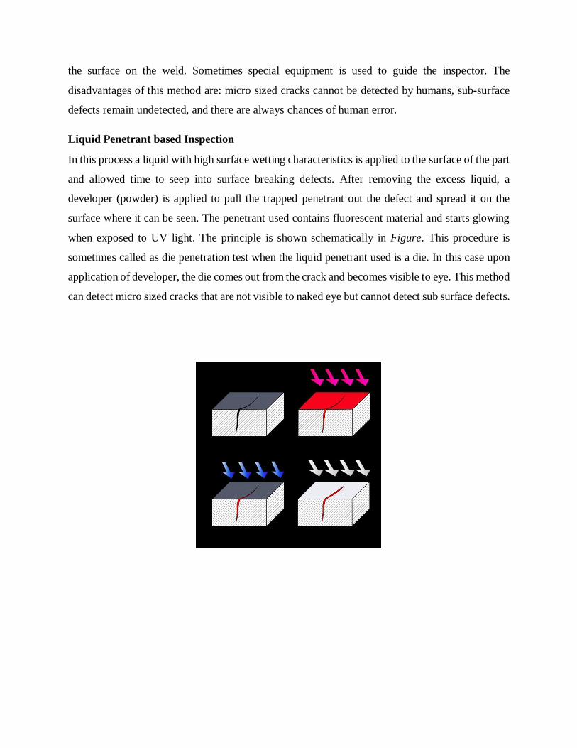
the surface on the weld. Sometimes special equipment is used to guide the inspector. The
disadvantages of this method are: micro sized cracks cannot be detected by humans, sub-surface
defects remain undetected, and there are always chances of human error.
Liquid Penetrant based Inspection
In this process a liquid with high surface wetting characteristics is applied to the surface of the part
and allowed time to seep into surface breaking defects. After removing the excess liquid, a
developer (powder) is applied to pull the trapped penetrant out the defect and spread it on the
surface where it can be seen. The penetrant used contains fluorescent material and starts glowing
when exposed to UV light. The principle is shown schematically in Figure. This procedure is
sometimes called as die penetration test when the liquid penetrant used is a die. In this case upon
application of developer, the die comes out from the crack and becomes visible to eye. This method
can detect micro sized cracks that are not visible to naked eye but cannot detect sub surface defects.

Figure (1) Crack, (2) Penetrant applied, (3) Developer applied, (4) Crack Visible
Magnetic Particle inspection
This method is based on the principle that magnetic lines change their paths whenever discontinuity
is encountered in the path. The first step in a magnetic particle inspection is to magnetize the
component that is to be inspected. After the component has been magnetized, iron particles, either
in a dry or wet suspended form, are applied to the surface of the magnetized part. The particles
will be attracted and cluster at the flux leakage fields, thus forming a visible indication that the
inspector can detect. It is a very simple procedure but applicable only for Ferromagnetic materials.
Often the material has to be demagnetised after performing the test.
Figure - Principle of Magnetic particles Inspection
Radiographic Testing
Radiographic Testing is a non-destructive testing method of inspecting materials for hidden
flaws by using the ability of short wavelength electromagnetic radiation (high energy photons) to
penetrate various materials. In this method the part is placed between the radiation source and a
piece of film. A pattern will be generated on the film depending on the thickness of the inspected
part. Where ever there is a defect, the amount of radiation absorbed will be different and

corresponding pattern will be generated. Detection of subsurface defects is the major advantage of
this test but proper safety measures have to be taken to prevent exposure to these radiations. The
figure schematically shows a typical radiographic testing set-up.
Ultrasonic Inspection
Ultrasonic testing uses the basic physical property that sound waves travel at known constant
velocities through any medium. By measuring the time for a sound wave to travel through a
material it can be determined how far that wave has travelled. In this way sound waves can be used
to measure distances. So, in an ultrasonic inspection, a high frequency sound wave is passes
through the material to be inspected. Presence and position of any defects can be detected by
analysing the sound wave reflected by the flaw. Figure - schematically shows a set-up for
ultrasonic testing of defects.
Various advantages of ultrasonic testing include – (a) high penetrating power leading to the
detection of flaws deep in the part, (b) high sensitivity, (c) greater accuracy than other non-
destructive methods in particular in determining the depth of internal flaws, (d) capability of
estimating the size, orientation, shape and nature of defects, (e) non-hazardous to operations or to
nearby personnel.
Besides these advantages it has few disadvantages too such as – (1) manual operation and hence,
requires careful attention, (2) experienced personnel are

required, (3) surface must be prepared by cleaning and removing loose scale, paint, etc.
Figure - Principle of Ultrasonic Testing
Huey Test for stainless steels
This test consists of exposure to boiling 65% nitric acid for five 48 hr periods. Sensitized
material exhibits high corrosion rates. Maleic acid, lactic acid, copper sulfate-sulfuric acid, and
ferric sulfate- sulphuric acid are also used to determine susceptibility to intergranular corrosion
of stainless steels.
Streicher test for stainless steels
The Huey test is time consuming and expensive. The test consists of polishing a small specimen
through no 000 emery paper etching in 10% oxalic acid for 1.5min under an applied current
density of 1 A/cm2 , and then examining the surface at 2580 to 500 magnification. The specimen
is the anode and a stainless steel beaker is the cathode.
Warren Test
Type 316L stainless steel poses a special problem in connection with the use of Huey test. When
sensitized for 1hr at 1250 deg F, type 316 L may form a sigma phase. Sigma containing material
shows high corrosion rates and fails Huey test. Warren proposes the use of 10% nitric acid – 3%
hydrofluoric acid mixture at 70 or 80 degree C to evaluate 316L type.


The rate and type of attack are found to be dependent on the type of salt, its concentration
and the period of test.
The type of attack varies from predominantly pitting in pure water to even etching in
strong magnesium and calcium salt solutions.
Applications of high temperature environments is boiling heat transfer equipment,
separation & extraction equipment, ionic liquids equip, high boiling equip, boiler ,heat
exchanger, evaporator, reactor etc..
Application of boiling also similar to application of high temperature environment.
This is the application of corrosion.
Top Related