


Languages
Pages
Legal


UML Modeling Guidelines
TR-514 v1.3-info July 2018

TR-514 UML Modeling Guidelines Version 1.3
Page 2 of 84 © Open Networking Foundation
Disclaimer
THIS SPECIFICATION IS PROVIDED “AS IS” WITH NO WARRANTIES
WHATSOEVER, INCLUDING ANY WARRANTY OF MERCHANTABILITY,
NONINFRINGEMENT, FITNESS FOR ANY PARTICULAR PURPOSE, OR
ANY WARRANTY OTHERWISE ARISING OUT OF ANY PROPOSAL,
SPECIFICATION OR SAMPLE.
Any marks and brands contained herein are the property of their respective owners.
Open Networking Foundation
1000 El Camino Real, Suite 100, Menlo Park, CA 94025
www.opennetworking.org
©2018 Open Networking Foundation. All rights reserved.
Open Networking Foundation, the ONF symbol, and OpenFlow are registered trademarks of the
Open Networking Foundation, in the United States and/or in other countries. All other brands,
products, or service names are or may be trademarks or service marks of, and are used to
identify, products or services of their respective owners.
Important note
This Technical Recommendations has been approved by the OIMT Project TST but has not been
approved by the ONF board. This Technical Recommendation has been approved under the ONF
publishing guidelines for 'Informational' publications that allow Project technical steering teams
(TSTs) to authorize publication of Informational documents. The designation of '-info' at the end
of the document ID also reflects that the project team (not the ONF board) approved this TR.

TR-514 UML Modeling Guidelines Version 1.3
Page 3 of 84 © Open Networking Foundation
Table of Contents
1 Introduction ......................................................................................................................................... 9
2 References ........................................................................................................................................... 9
3 Abbreviations ...................................................................................................................................... 9
4 Overview ............................................................................................................................................ 10
4.1 Documentation Overview ............................................................................................................ 10
4.2 Modeling approach ..................................................................................................................... 11
4.3 General Requirements ................................................................................................................ 12
4.4 General Information on the UML Model...................................................................................... 12
5 UML Artifact Descriptions ................................................................................................................ 13
5.1 Structural/behavioral features ..................................................................................................... 13
5.2 Classes ....................................................................................................................................... 14
5.2.1 Description ........................................................................................................................ 14
5.2.2 Class Notation .................................................................................................................. 14
5.2.3 Class Properties ............................................................................................................... 15
5.3 Attributes in Classes ................................................................................................................... 18
5.3.1 Description ........................................................................................................................ 18
5.3.2 Attribute Notation .............................................................................................................. 18
5.3.3 Attribute Properties ........................................................................................................... 18
5.3.4 Attribute Setability ............................................................................................................. 23
5.4 Relationships .............................................................................................................................. 25
5.4.1 Description ........................................................................................................................ 25
5.4.2 Relationship Notation ....................................................................................................... 26
5.4.3 Relationship Properties .................................................................................................... 33
5.5 Interfaces .................................................................................................................................... 37
5.5.1 Description ........................................................................................................................ 37
5.5.2 «Interface» Notation ......................................................................................................... 37
5.5.3 «Interface» Properties ...................................................................................................... 38
5.6 Interface Operations ................................................................................................................... 39
5.6.1 Description ........................................................................................................................ 39
5.6.2 Operation Notation ........................................................................................................... 39
5.6.3 Operation Properties ........................................................................................................ 39
5.7 Operation Parameters................................................................................................................. 42
5.7.1 Description ........................................................................................................................ 42
5.7.2 Parameter Notation .......................................................................................................... 42
5.7.3 Parameter Properties ....................................................................................................... 42
5.8 Notifications ................................................................................................................................ 44
5.8.1 Description ........................................................................................................................ 44

TR-514 UML Modeling Guidelines Version 1.3
Page 4 of 84 © Open Networking Foundation
5.8.2 Notification Notation ......................................................................................................... 44
5.8.3 Notification Properties ...................................................................................................... 44
5.9 Data Types .................................................................................................................................. 46
5.9.1 Description ........................................................................................................................ 46
5.9.2 Type Notation ................................................................................................................... 46
5.9.3 Type Properties ................................................................................................................ 47
5.9.4 UML Primitive Types ........................................................................................................ 48
5.9.5 Pre-defined Data Types .................................................................................................... 49
5.10 Qualifiers and Conditions ............................................................................................................ 52
5.11 Use Cases .................................................................................................................................. 53
5.12 Activities ...................................................................................................................................... 54
5.13 State Machines ........................................................................................................................... 55
6 UML Profile Definitions ..................................................................................................................... 55
6.1 UML Profile Structure.................................................................................................................. 55
6.2 Additional Properties for the General Information on the UML Model ........................................ 56
6.3 Additional Common Properties for individual UML Model artifacts ............................................ 56
6.4 Additional Interface related Properties for individual UML Model artifacts ................................. 61
6.5 Additional Properties for all UML artifacts................................................................................... 63
6.5.1 Description ........................................................................................................................ 63
6.5.2 LifecycleState Property ..................................................................................................... 63
6.5.3 Profile LifecycleState Property ......................................................................................... 65
6.5.4 Reference Property .......................................................................................................... 68
6.5.5 Example Property ............................................................................................................. 69
7 Recommended Modeling Patterns .................................................................................................. 69
7.1 File Naming Conventions ............................................................................................................ 69
7.2 Model Structure ........................................................................................................................... 69
7.2.1 Generic Model Structure ................................................................................................... 69
7.2.2 Model Structure ................................................................................................................ 70
7.3 Flexible Attribute Assignment to Classes ................................................................................... 71
7.4 Use of Conditional Packages ...................................................................................................... 72
7.5 Use of XOR ................................................................................................................................. 73
7.5.1 Description ........................................................................................................................ 73
7.5.2 Examples .......................................................................................................................... 73
7.5.3 Name style ........................................................................................................................ 76
7.5.4 «Choice» (Obsolete) ......................................................................................................... 77
7.6 Proxy Class Modeling ................................................................................................................. 78
7.7 «LifecycleAggregate» Aggregation Usage ................................................................................. 79
7.8 Diagram Guidelines .................................................................................................................... 82
7.8.1 Generic Diagram Guidelines ............................................................................................ 82
7.8.2 Using Colors ..................................................................................................................... 82
7.8.3 Style Sheets ...................................................................................................................... 82
8 Main Changes between Releases .................................................................................................... 83

TR-514 UML Modeling Guidelines Version 1.3
Page 5 of 84 © Open Networking Foundation
8.1 Summary of main changes between version 1.0 and 1.1 ........................................................... 83
8.2 Summary of main changes between version 1.1 and 1.2 ........................................................... 83
8.3 Summary of main changes between version 1.2 and 1.3 ........................................................... 84
List of Figures
Figure 4.1: Specification Architecture ......................................................................................................... 11
Figure 5.1: Structural/Behavioral Features in UML 2.5 Metamodel ............................................................ 13
Figure 5.2: Graphical Notation for Classes ................................................................................................. 14
Figure 5.3: Graphical Notation for Classes without Attributes Compartment ............................................. 14
Figure 5.4: Graphical Notation for Classes with Attributes and Deprecated Operations Compartment ..... 15
Figure 5.5: «OpenModelClass» Stereotype ................................................................................................ 16
Figure 5.6: «OpenInterfaceModelClass» Stereotype (obsolete) ................................................................. 16
Figure 5.7: Potential Choice Annotation for Classes (obsolete) ................................................................. 17
Figure 5.8: Optional RootElement Annotation for Classes ......................................................................... 17
Figure 5.9: Graphical Notation for Classes with Attributes ......................................................................... 18
Figure 5.10: «OpenModelAttribute» Stereotype ......................................................................................... 20
Figure 5.11: uniqueSet usage example ...................................................................................................... 20
Figure 5.12: «OpenInterfaceModelAttribute» Stereotype ........................................................................... 21
Figure 5.13: Bit Definition Properties .......................................................................................................... 22
Figure 5.14: Potential Annotations for Attributes ........................................................................................ 23
Figure 5.15: Example Modeling of a Bit Set Data Type .............................................................................. 23
Figure 5.16: Actors setting the Attribute Value ........................................................................................... 24
Figure 5.17: Metaclass Diagram of used Relationships ............................................................................. 26
Figure 5.18: Bidirectional Association Relationship Notations .................................................................... 26
Figure 5.19: Unidirectional Association Relationship Notation ................................................................... 27
Figure 5.20: – Non-navigable Association Relationship Notation ............................................................... 27
Figure 5.21: – Reference Pointer to Classes with more than one Composition Aggregation Association Relationship Notation ........................................................................................................................... 28
Figure 5.22: Aggregation Association Relationship Notation ...................................................................... 28
Figure 5.23: «LifecycleAggregate» Aggregation Association Relationship Notation .................................. 29
Figure 5.24: Composite Aggregation Association Relationship Notation ................................................... 30
Figure 5.25: «StrictComposite» Aggregation Association Relationship Notation ....................................... 30
Figure 5.26: «ExtendedComposite» Aggregation Association Relationship Notation ................................ 30
Figure 5.27: Generalization Relationship Notation (normal, conditional and example) .............................. 31

TR-514 UML Modeling Guidelines Version 1.3
Page 6 of 84 © Open Networking Foundation
Figure 5.28: Dependency Relationship Notation (normal and naming) ...................................................... 31
Figure 5.29: Usage Dependency Notation .................................................................................................. 32
Figure 5.30: Abstraction Dependency Notation .......................................................................................... 32
Figure 5.31: Conditional «Specify» Abstraction Relationship Example ...................................................... 33
Figure 5.32: Realization Dependency Notation .......................................................................................... 33
Figure 5.33: Owner of a navigable Member End ........................................................................................ 34
Figure 5.34: Potential Annotations for Associations ................................................................................... 37
Figure 5.35: Graphical Notation for «Interface» .......................................................................................... 38
Figure 5.36: Graphical Notation for «Interface» without Attributes Compartment ...................................... 38
Figure 5.37: «OpenModelInterface» Stereotype ......................................................................................... 39
Figure 5.38: Graphical Notation for «Interface» with Operations................................................................ 39
Figure 5.39: «OpenModelOperation» Stereotype ....................................................................................... 41
Figure 5.40: Graphical Notation for «Interface» with Operations and Parameters ..................................... 42
Figure 5.41: «OpenModelParameter» Stereotype ...................................................................................... 43
Figure 5.42: «PassedByReference» Stereotype......................................................................................... 44
Figure 5.43: Graphical Notation for «Signal» .............................................................................................. 44
Figure 5.44: «OpenModelNotification» Stereotype ..................................................................................... 45
Figure 5.45: Notification Trigger Condition List ........................................................................................... 45
Figure 5.46: Trigger Condition List Pop-up ................................................................................................. 45
Figure 5.47: Graphical Notation for «DataType» ........................................................................................ 46
Figure 5.48: Graphical Notation for «Enumeration» ................................................................................... 46
Figure 5.49: Graphical Notation for «PrimitiveType» .................................................................................. 47
Figure 5.50: Defining an Integer Value for a Literal .................................................................................... 47
Figure 5.51: Potential Annotations for Data Types ..................................................................................... 48
Figure 5.52: Primitive Types provided by Papyrus ..................................................................................... 48
Figure 5.53: Common Data Types Grouping .............................................................................................. 50
Figure 5.54: Core and Implementation Common Data Types .................................................................... 50
Figure 5.55: Conditional Class Example ..................................................................................................... 53
Figure 5.56: Conditional Attributes Example............................................................................................... 53
Figure 5.57: Example of Use Case Diagram .............................................................................................. 54
Figure 5.58: Example Business Process Modeling .................................................................................... 55
Figure 6.1: UML Profile Structure ............................................................................................................... 56
Figure 6.2: OpenModelStatement Required «Stereotype» ......................................................................... 56

TR-514 UML Modeling Guidelines Version 1.3
Page 7 of 84 © Open Networking Foundation
Figure 6.3: OpenModel Profile: Required «Stereotypes» ........................................................................... 57
Figure 6.4: OpenModel Profile: Optional «Stereotypes» ............................................................................ 58
Figure 6.5: OpenInterfaceModel Profile: Required «Stereotypes» ............................................................. 61
Figure 6.6: OpenInterfaceModel Profile: Optional «Stereotypes» .............................................................. 62
Figure 6.7: Lifecycle «Stereotypes» ............................................................................................................ 65
Figure 6.8: Profile Lifecycle «Stereotypes» ................................................................................................ 67
Figure 6.9: Lifecycle and ProfileLifecycle LifecycleState State Machine .................................................... 68
Figure 6.10: Reference «Stereotype» ......................................................................................................... 69
Figure 6.11: Example «Stereotype» ........................................................................................................... 69
Figure 7.1: Core Model and SubModels ..................................................................................................... 70
Figure 7.2: Model Structure (snapshot) ...................................................................................................... 71
Figure 7.3: Pre-defined Packages at the Bottom Level of each UML Model (Example) ............................ 71
Figure 7.4: Flexible Attribute Assignment to Classes ................................................................................. 72
Figure 7.5: Enhancing Classes Using Conditional Packages ..................................................................... 73
Figure 7.6: {xor} Alternative Example ......................................................................................................... 74
Figure 7.7: {xor} Probable Cause Type Example ....................................................................................... 74
Figure 7.8: {xor} Parent / Child Example ..................................................................................................... 75
Figure 7.9: Multi Level {xor} Example ......................................................................................................... 76
Figure 7.10: Information Model Element Example Using «Choice» Notation ............................................. 77
Figure 7.11: Operations Model Element Example Using «Choice» Notation ............................................. 78
Figure 7.12: Sink/Source/Bidirectional Termination Points Example Using «Choice» Notation ................ 78
Figure 7.13: Proxy Class Modeling Example .............................................................................................. 79
Figure 7.14: Usage Example for «LifecycleAggregate» Aggregation Association ..................................... 80
Figure 7.15: Instance Example for «LifecycleAggregate» Aggregation Association .................................. 81
List of Tables
Table 5.1: Table 11.1/[3] – Collection Types for Properties ........................................................................ 19
Table 5.2: Allowed combinations of isInvariant and writeAllowed .............................................................. 25
Table 6.1: OpenModel Profile: Complex «Stereotypes» ............................................................................. 58
Table 6.2: OpenInterfaceModel Profile: Complex «Stereotypes» ............................................................... 62

TR-514 UML Modeling Guidelines Version 1.3
Page 8 of 84 © Open Networking Foundation
Document History
Version Date Description of Change
1.0 March 13,
2015 Initial version
1.1 Nov. 30, 2015
Version 1.1
A summary of main changes between version 1.0 and 1.1 is contained in section
8.1.
1.2 Sept. 20, 2016
Version 1.2
A summary of main changes between version 1.1 and 1.2 is contained in section
8.2.
1.3 July 2018
Version 1.3
A summary of main changes between version 1.2 and 1.3 is contained in section
8.3.
TR-514 UML Modeling Guidelines Version 1.3
Page 9 of 84 © Open Networking Foundation
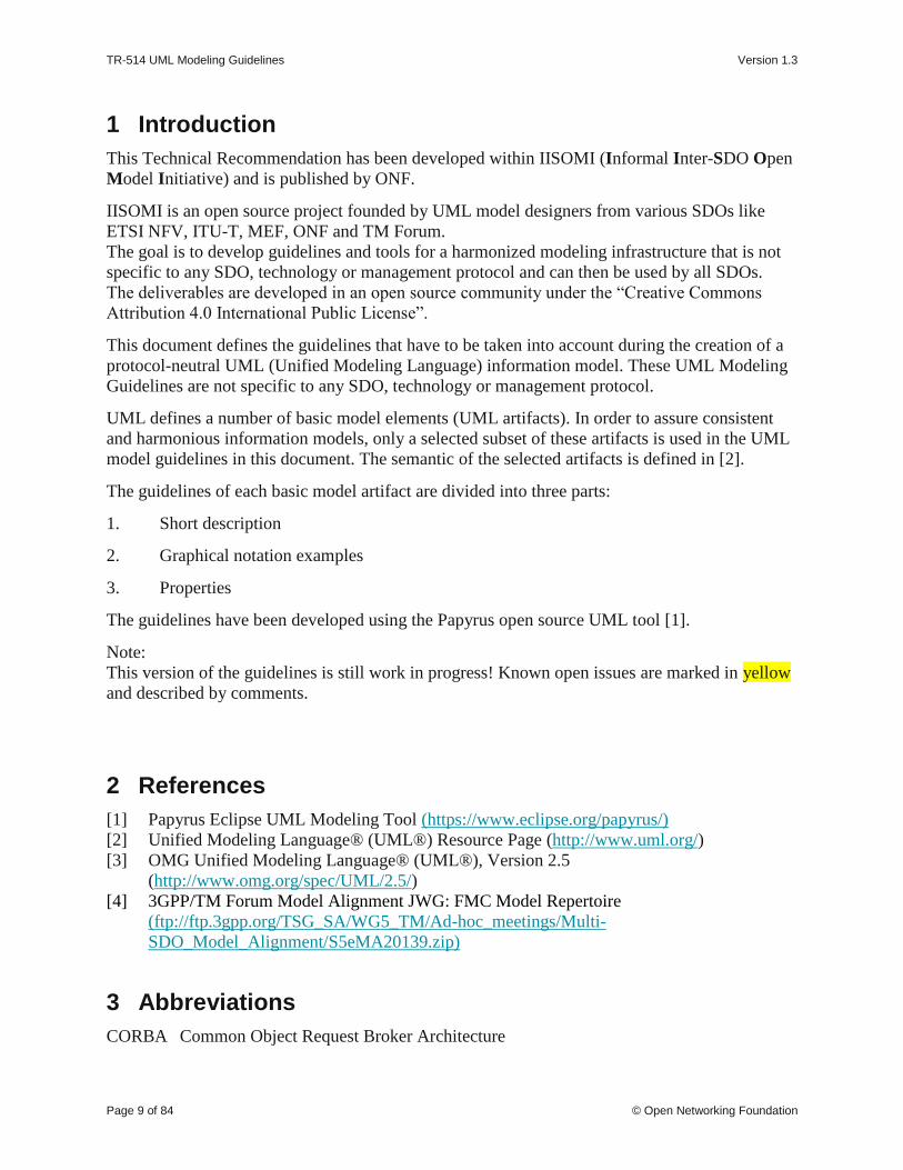
1 Introduction
This Technical Recommendation has been developed within IISOMI (Informal Inter-SDO Open
Model Initiative) and is published by ONF.
IISOMI is an open source project founded by UML model designers from various SDOs like
ETSI NFV, ITU-T, MEF, ONF and TM Forum.
The goal is to develop guidelines and tools for a harmonized modeling infrastructure that is not
specific to any SDO, technology or management protocol and can then be used by all SDOs.
The deliverables are developed in an open source community under the “Creative Commons
Attribution 4.0 International Public License”.
This document defines the guidelines that have to be taken into account during the creation of a
protocol-neutral UML (Unified Modeling Language) information model. These UML Modeling
Guidelines are not specific to any SDO, technology or management protocol.
UML defines a number of basic model elements (UML artifacts). In order to assure consistent
and harmonious information models, only a selected subset of these artifacts is used in the UML
model guidelines in this document. The semantic of the selected artifacts is defined in [2].
The guidelines of each basic model artifact are divided into three parts:
1. Short description
2. Graphical notation examples
3. Properties
The guidelines have been developed using the Papyrus open source UML tool [1].
Note:
This version of the guidelines is still work in progress! Known open issues are marked in yellow
and described by comments.
2 References
[1] Papyrus Eclipse UML Modeling Tool (https://www.eclipse.org/papyrus/)
[2] Unified Modeling Language® (UML®) Resource Page (http://www.uml.org/)
[3] OMG Unified Modeling Language® (UML®), Version 2.5
(http://www.omg.org/spec/UML/2.5/)
[4] 3GPP/TM Forum Model Alignment JWG: FMC Model Repertoire
(ftp://ftp.3gpp.org/TSG_SA/WG5_TM/Ad-hoc_meetings/Multi-
SDO_Model_Alignment/S5eMA20139.zip)
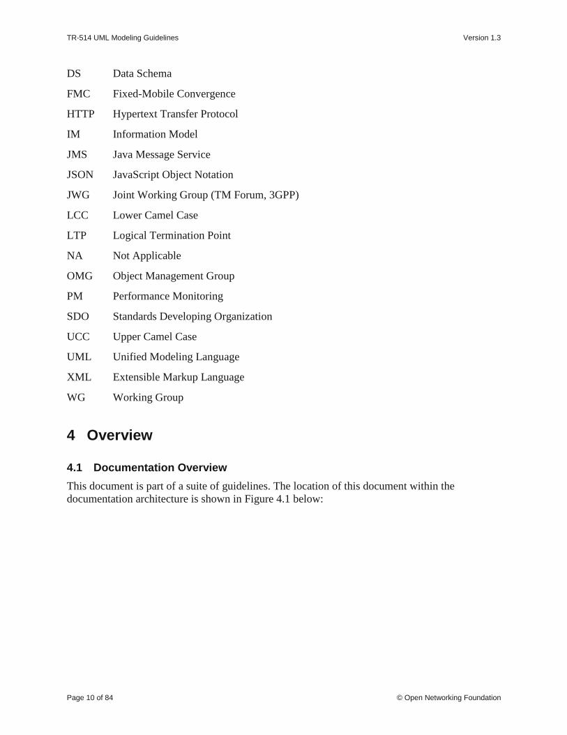
3 Abbreviations
CORBA Common Object Request Broker Architecture
TR-514 UML Modeling Guidelines Version 1.3
Page 10 of 84 © Open Networking Foundation
DS Data Schema
FMC Fixed-Mobile Convergence
HTTP Hypertext Transfer Protocol
IM Information Model
JMS Java Message Service
JSON JavaScript Object Notation
JWG Joint Working Group (TM Forum, 3GPP)
LCC Lower Camel Case
LTP Logical Termination Point
NA Not Applicable
OMG Object Management Group
PM Performance Monitoring
SDO Standards Developing Organization
UCC Upper Camel Case
UML Unified Modeling Language
XML Extensible Markup Language
WG Working Group
4 Overview
4.1 Documentation Overview
This document is part of a suite of guidelines. The location of this document within the
documentation architecture is shown in Figure 4.1 below:

TR-514 UML Modeling Guidelines Version 1.3
Page 11 of 84 © Open Networking Foundation
IISOMI / Bernd Zeuner (DT)
UML to DS MappingGuidelines
Core Fragment
Technologyspecific
…
SpecificFragments
Appspecific
Gu
idel
ines
YANG
xx
guid
e
Interface-specificData Schemas
xx
xx
Interface-specificEncodings
mapping
mapping
mappinggu
ide
pruningre-factoring
pruningre-factoring
pruningre-factoring
a
Purpose-specificIMs
b
guid
e
guid
e
UM
L M
od
els
TR-513: Common Information Model Overview(structure, development process)
guid
e
guid
e
guid
e
guid
e
guid
e
guid
e
guid
e
xx
Common Information Model
c
z
TR-512: Core Network (Forwarding, Topology,
Termination, Foundation, …)
IISOMI 531: UMLto YANG Mapping
Guidelines
Tooling
UML|
YANG
UML|
JSON
UML|
TOSCA
UML|
protobuf
multiSDO
IISOMI
Figure 4.1: Specification Architecture
4.2 Modeling approach
The information model is split into a structural part and a behavioral part; i.e., data model
(structural/static) is decoupled from operations model (behavioral/dynamic).
Important note:
It is important to understand that the UML class diagrams always show only parts of the
underlying model. E.g., classes shown without attributes do not mean that the class has no
attribute, i.e., attributes could be hidden in a diagram. The full model can be viewed in its
entirety through the UML tool (i.e., Papyrus; XMI codes in the .uml file) and a view of key
details is provided in a data dictionary.
Also note that in this document, use of the term “Class” refers to a UML class, unless otherwise
specified.

TR-514 UML Modeling Guidelines Version 1.3
Page 12 of 84 © Open Networking Foundation
4.3 General Requirements
• UML 2.5 (Unified Modeling Language) is used for specifying the model.
• The model shall be management/control protocol-neutral, i.e., not reflect any middleware
protocol-specific characteristics (like e.g., CORBA, HTTP, JMS).
• The model shall be map-able to various protocol-specific interfaces.
It is recommended to automate this mapping supported by tools.
• To ensure proper working of the mapping tools, the model designer shall only use the
modeling patterns defined in these guidelines. Use of other UML patterns is at the own
risk of the model designer.
• It shall be possible to separate UML artifact properties which are only required for
interface related (purpose specific) models.
• Traceability from each modeling construct back to requirements and use cases shall be
provided whenever possible.
4.4 General Information on the UML Model
The following general information on the model shall be set/defined:
• Namespace
A unique and persistent namespace for the identifiers in the model.
• Organization
A human friendly written name of the SDO/OpenSource Project defining the model.
• Contact
Detailed information on the project and editor which have developed the model.
o Project web site
The URL of the project web site.
o Project email address
The e-mail address of the project.
o Editor name
The name of the model editor (optional). It is recommended that editor name be a
persistent role name instead or a personal name because of the possibility of the
person’s role change.
o Editor email address
The e-mail address of the model editor (optional). It is recommended that editor
email address be a persistent address instead of a personal email address because
of the possibility of the person’s role change.
• Description
A brief description of the model content; 1 line (optional).
• Copyright
The copyright notice for the model.
• License
The license statement for the model.

TR-514 UML Modeling Guidelines Version 1.3
Page 13 of 84 © Open Networking Foundation
• Revision
Detailed information on this revision of the model. Each revision of the model should add
an additional revision statement.
o Date
The date of the revision.
o Version
The project and the version of the revision.
o Description
An additional specific description of the revision (optional).
o Change log pointer
A link to a github UML change log (optional).
o Additional changes
A list of additional manual changes (optional).
o Reference
A list of referenced documents in the revision (optional).
5 UML Artifact Descriptions
5.1 Structural/behavioral features
The UML 2.5 specification [3] distinguishes between structural and behavioral features. The
structural modeling is using Attributes (Properties) contained in Classes and the behavioral
modeling is using Operations contained in Interfaces.
Figure 5.1: Structural/Behavioral Features in UML 2.5 Metamodel
The decoupling of attributes and operations allows a model designer to provide individual
operations (specific parameter lists) for different views/managers.
TR-514 UML Modeling Guidelines Version 1.3
Page 14 of 84 © Open Networking Foundation
5.2 Classes
5.2.1 Description
Classes are used to convey a structural (often called static)1 representation of an entity, including
properties and attributes; i.e., data model, the structural part of the model.
5.2.2 Class Notation
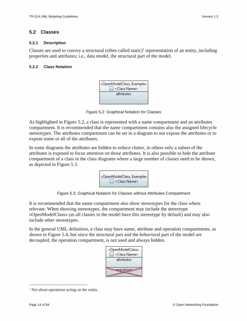
Figure 5.2: Graphical Notation for Classes
As highlighted in Figure 5.2, a class is represented with a name compartment and an attributes
compartment. It is recommended that the name compartment contains also the assigned lifecycle
stereotypes. The attributes compartment can be set in a diagram to not expose the attributes or to
expose some or all of the attributes.
In some diagrams the attributes are hidden to reduce clutter, in others only a subset of the
attributes is exposed to focus attention on those attributes. It is also possible to hide the attribute
compartment of a class in the class diagrams where a large number of classes need to be shown,
as depicted in Figure 5.3.
Figure 5.3: Graphical Notation for Classes without Attributes Compartment
It is recommended that the name compartment also show stereotypes for the class where
relevant. When showing stereotypes, the compartment may include the stereotype
«OpenModelClass» (as all classes in the model have this stereotype by default) and may also
include other stereotypes.
In the general UML definition, a class may have name, attribute and operation compartments, as
shown in Figure 5.4, but since the structural part and the behavioral part of the model are
decoupled, the operation compartment, is not used and always hidden.
1 Not about operations acting on the entity.

TR-514 UML Modeling Guidelines Version 1.3
Page 15 of 84 © Open Networking Foundation
Figure 5.4: Graphical Notation for Classes with Attributes and Deprecated Operations Compartment
5.2.3 Class Properties
A class has the following properties:
• Name
Follows Upper Camel Case style (UCC). Each class in the model has a unique name. An
example of Upper Camel Case: SubNetworkConnection.
• Documentation
Contains a short definition. The documentation is carried in the “Applied comments”
field in Papyrus; i.e., the “Owned comments” field shall not be used. The complete
documentation should be written in a single comment; i.e., at most one “Applied
comment”.
2
• Superclass(es)
Inheritance and multiple inheritance may be used to deal with shared properties.
• Abstract
Indicates if the object class can be instantiated or is just used for inheritance; i.e., abstract
classes will not be instantiated.
• Is Leaf
Indicates that the object class must not be extended (Is Leaf = true); default = false.
• Additional properties are defined in the «OpenModelClass» stereotype which extends
( ) by default (required) the «metaclass» Class:
2 Because of Papyrus tool reasons, you shall not create comments directly in the class diagram and attach it by a link
to the class. Such comments appear in applied comments field too, BUT they don’t appear in the gendoc output.

TR-514 UML Modeling Guidelines Version 1.3
Page 16 of 84 © Open Networking Foundation
Figure 5.5: «OpenModelClass» Stereotype
• support
This property qualifies the support of the class class at the management interface. See
definition in clause 5.10.
• condition
This property contains the condition for the condition-related support qualifiers.
• Obsolete
Additional interface related properties (only relevant in the purpose-specific models of
the information model; see Figure 4.1) are defined in the «OpenInterfaceModelClass»
stereotype which extends
( ) by default (required) the «metaclass» Class:
Figure 5.6: «OpenInterfaceModelClass» Stereotype (obsolete)
• objectCreationNotification
Defines whether an object creation notification has to be sent when the instance is
created.
• objectDeletionNotification
Defines whether an object deletion notification has to be sent when the instance is
deleted.
• Other properties:
• Choice (obsolete)
This optional stereotype identifies a class as a choice between different alternatives.

TR-514 UML Modeling Guidelines Version 1.3
Page 17 of 84 © Open Networking Foundation
Figure 5.7: Potential Choice Annotation for Classes (obsolete)
• RootElement
This optional stereotype is only relevant in interface related (purpose-specific) models
and identifies the associated object class as the root element when mapped to a tree
structured data model.
The name property specifies the name for the root instance.
The multiplicity property defines the constraint of the number of root elements in the
data model. The format is similar to the UML multiplicity; i.e., <lower
bound>..<upper bound>. E.g., "0..*", "2..3", "1..*".
The optional description property will be mapped e.g., in YANG to the presence
statement.
Figure 5.8: Optional RootElement Annotation for Classes
The following UML defined class properties are not used:
• Is active (default = false)
• Visibility (default = public)

TR-514 UML Modeling Guidelines Version 1.3
Page 18 of 84 © Open Networking Foundation
5.3 Attributes in Classes
5.3.1 Description
Attributes contain the properties3 of a class. Note that the roles of navigable association ends
become an attribute in the class at the other associated end when this association end is owned by
the classifier; see also “Role Type” property in clause 5.4.3.
Note: The association end can also be owned by the association itself in which case it does not
become an attribute.
5.3.2 Attribute Notation
The notation is:
|«<list of stereotypes>»| <visibility> <attribute name> : <attribute type> [<multiplicity>] =
<default value>
Note: When no default is relevant or no default is defined, the “=” is not shown.
Figure 5.9: Graphical Notation for Classes with Attributes
Note: It is recommended to display either no attributes or all attributes of the object classes in
given class diagram.
It is also permissible to display only a subset of the attributes (e.g., to allow the drawing of a
class diagram displaying only the required attributes of a specific feature) BUT in this case, it is
recommended to warn the reader of such a class diagram by an appropriate note.
5.3.3 Attribute Properties
An attribute has the following properties:
• Name
Follows Lower Camel Case (LCC) style and is unique across all attribute names within
the inheritance tree. An example of Lower Camel Case:
subNetworkConnectionIdentifier.
It is recommended that all Boolean typed attribute names start with ‘is’ (e.g.,
‘isAbstract’), ‘must’ or a verb such as ‘has’ and the whole attribute name shall be
composed in a way that it is possible to answer it by "true" or "false".
• Documentation
Contains a short definition. The documentation is carried in the “Applied comments”
field in Papyrus; i.e., the “Owned comments” field shall not be used. The complete
documentation should be written in a single comment; i.e., at most one “Applied
comment”.
3 In Papyrus an attribute is a property.

TR-514 UML Modeling Guidelines Version 1.3
Page 19 of 84 © Open Networking Foundation
• Ordered
For a multi-valued multiplicity; this specifies whether the values in an instantiation of
this attribute are sequentially ordered; default is false.
• Unique
For a multi-valued multiplicity, this specifies if the values of this attribute instance are
unique (i.e., no duplicate attribute values); default is true.
Excerpt from [3]: When Unique is true (the default), the collection of values may not
contain duplicates. When Ordered is true (false being the default) the collection of values
is ordered. In combination these two allow the type of a property to represent a collection
in the following way:
Table 5.1: Table 11.1/[3] – Collection Types for Properties
Ordered Unique Collection type
false true Set
true true OrderedSet
false false Bag
true false Sequence
• Is Leaf
Indicates if the attribute definition is either fully consolidated (Is Leaf = true) or is not
fully consolidated / cannot be consolidated (Is Leaf = false). E.g., in case of an
Enumeration typed attribute, because the associated set of Literals is known to be open
(or has to be left open) for future yet not known or not consolidated extensions.
Default = false.
• Type
Refers to a data type; see clause 5.9.
• Default Value
Provides the value that the attribute has to start with in case the value is not provided
during creation, or already defined because of a system state.
• Multiplicity (*, 1, 1..*, 0..1, …)
Defines the number of values the attribute can simultaneously have.
* is a list attribute with 0, one or multiple values;
1 attribute has always one value;
1..* is a list attribute with at least one value;
0..1 attribute may have no or at most one value;
Default value is 1.
Other values are possible; e.g., “2..17”.
• Additional properties are defined in the «OpenModelAttribute» stereotype which extends
( ) by default (required) the «metaclass» Property:

TR-514 UML Modeling Guidelines Version 1.3
Page 20 of 84 © Open Networking Foundation
Figure 5.10: «OpenModelAttribute» Stereotype
• partOfObjectKey
This property indicates if the attribute is part of the object key or not.
Value = 0 (default) means the attribute is not part of the object key.
Values > 0 indicate that the attribute is part of the object key and the value defines the
order of the attribute in case the key is composed of more than one attribute.
Attributes which are used as a key shall be invariant (i.e., property isInvariant = true),
shall not be optional (i.e., the multiplicity shall be [1] or [1..x]) and the multiplicity
shall be [1] after the Pruning&Refactoring process; i.e., a UML to Data Schema
mapping tool shall not get a list attribute which is part of the object identifier.
• uniqueSet
This property defines if the attribute is part of a set of attributes which together (i.e.,
their values) have to be unique among all instances within a defined context.
No value means no uniqueness constraint.
An integer value identifies the uniqueness set.
An attribute may participate in more than one uniqueness sets.
Figure 5.11: uniqueSet usage example
• isInvariant
This property identifies if the value of the attribute can be changed after it has been
created; see also section 5.3.4.
TR-514 UML Modeling Guidelines Version 1.3
Page 21 of 84 © Open Networking Foundation
• valueRange
This property identifies the allowed values for the attribute.
• unsigned
This optional property indicates if the attribute type is unsigned (value = true) or
signed (value = false); if applicable, otherwise ignored.
• counter
This optional property defines the counter type of the attribute type; if applicable.
• unit
This optional property contains a textual definition of the unit associated with the
attribute value.
The spelling of the unit, including the ones beyond SI scope, shall be in accordance to
the NIST Publication 811 “Guide for the Use of the International System of Units
(SI)” (http://www.nist.gov/pml/pubs/sp811/index.cfm), clause 9 “Rules and Style
Conventions for Spelling Unit Names” as modified by the ISO/IEC 80000 series
documents (https://www.iso.org/committee/46202.html).
• support
This property qualifies the support of the attribute at the management interface. See
definition in clause 5.10
• condition
This property contains the condition for the condition-related support qualifiers.
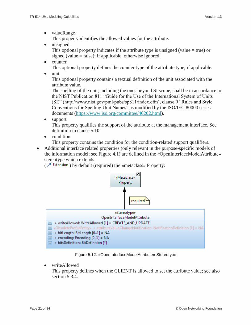
• Additional interface related properties (only relevant in the purpose-specific models of
the information model; see Figure 4.1) are defined in the «OpenInterfaceModelAttribute»
stereotype which extends
( ) by default (required) the «metaclass» Property:
Figure 5.12: «OpenInterfaceModelAttribute» Stereotype
• writeAllowed
This property defines when the CLIENT is allowed to set the attribute value; see also
section 5.3.4.

TR-514 UML Modeling Guidelines Version 1.3
Page 22 of 84 © Open Networking Foundation
• attributeValueChangeNotification (obsolete)
This property defines whether a notification has to be raised when the attribute
changes its value or not.
• bitLength
This optional property defines the bit length of the attribute type; if applicable.
• encoding
This optional property defines the encoding of the attribute type; if applicable.
• bitsDefinition (preliminary solution 1)
This optional property defines the bits (flags) of a Bits typed attribute. Each bit is
further defined by its name, position, support and an optional description. The default
setting of each bit is defined in the default value of the Bits typed attribute; i.e., all
bits contained in the default value are set to “1”.
Figure 5.13: Bit Definition Properties
• Other properties:
• «PassedByReference»
This stereotype shall only be applied to attributes that have a class defined as their
type; i.e., association member ends owned by the class which became attributes. The
stereotype is applied on a case by case basis.
The property defines that the attribute contains only the reference (name, identifier,
address) of the referred instance(s) when being transferred across the interface.
Otherwise the attribute contains the complete information of the instance(s) when
being transferred across the interface.
• «Bit» (preliminary solution2)
This optional stereotype defines the position of a bit typed attribute in a «Bits»
annotated data type.

TR-514 UML Modeling Guidelines Version 1.3
Page 23 of 84 © Open Networking Foundation
Figure 5.14: Potential Annotations for Attributes
Figure 5.15: Example Modeling of a Bit Set Data Type
The following UML defined attribute properties are not used:
• Is read only (default value = false)
• Is derived (default = false)
• Is derived union (default = false)
• Is static (default = false)
• Visibility (default = public)
5.3.4 Attribute Setability
UML model designers need to be able to define the “setability” of attribute values. Standard
UML provides a Boolean property called “readOnly”. Since this is not enough to describe all
required cases “readOnly” is not used and two additional properties isInvariant and writeAllowed
are defined.
From information model point of view (context) an attribute value can be set by two different
actors (a) directly by the client or (b) from elsewhere.

TR-514 UML Modeling Guidelines Version 1.3
Page 24 of 84 © Open Networking Foundation
Server
ObjectInstance:ObjectClass
attribute:value
Client
Underlying
System
Contextsetting value directly
setting valuefrom elesewhere
setting value indirectly
settingvalue fromelsewhere
another
Client
Figure 5.16: Actors setting the Attribute Value
Legend:
• Red arrow
Setting of attribute is initiated directly by the client; i.e., setAttribute().
• Blue arrow
Setting of the attribute value has not been initiated directly by the client; i.e., is set from
elsewhere (e.g., indirectly by the client, other clients, server, underlying system).
Client, Server and Underlying System in the figure are at one level of recursion. There may be
many other levels below the Underlying System or above the Client.
One extreme example is the entire operator’s business represented by the Server. Another
extreme example is when the Server represents a thin mediator on top of the traffic functions
(Underlying System).
The isInvariant property identifies (system wide) if the value of the attribute can be changed after
it has been created (isInvariant = false) or not (isInvariant = true).
The writeAllowed property defines (from the client point of view only) when the client is
directly allowed to set the attribute value. This can be {only during creation | only after creation |
during and after creation | at no time}; all values are mutually exclusive.
TR-514 UML Modeling Guidelines Version 1.3
Page 25 of 84 © Open Networking Foundation
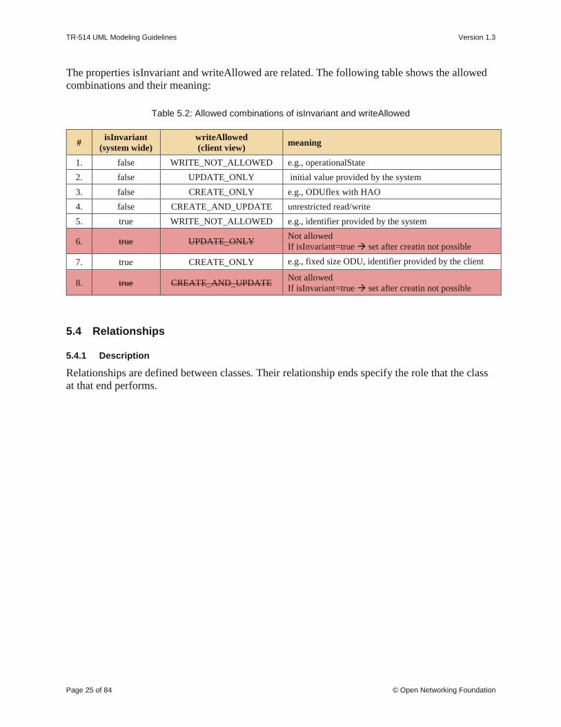
The properties isInvariant and writeAllowed are related. The following table shows the allowed
combinations and their meaning:
Table 5.2: Allowed combinations of isInvariant and writeAllowed
# isInvariant
(system wide)
writeAllowed
(client view) meaning
1. false WRITE_NOT_ALLOWED e.g., operationalState
2. false UPDATE_ONLY initial value provided by the system
3. false CREATE_ONLY e.g., ODUflex with HAO
4. false CREATE_AND_UPDATE unrestricted read/write
5. true WRITE_NOT_ALLOWED e.g., identifier provided by the system
6. true UPDATE_ONLY Not allowed
If isInvariant=true → set after creatin not possible
7. true CREATE_ONLY e.g., fixed size ODU, identifier provided by the client
8. true CREATE_AND_UPDATE Not allowed
If isInvariant=true → set after creatin not possible
5.4 Relationships
5.4.1 Description
Relationships are defined between classes. Their relationship ends specify the role that the class
at that end performs.

TR-514 UML Modeling Guidelines Version 1.3
Page 26 of 84 © Open Networking Foundation
Figure 5.17: Metaclass Diagram of used Relationships
5.4.2 Relationship Notation
The following examples show the different kinds of relationships that are used in the model.
5.4.2.1 Association Notation
Figure 5.18 shows a bi-directional navigable association where each class has a pointer to the
other. The association end role name becomes the name of the corresponding attribute. I.e., in the
example: ClassA will have an attribute named “_classB” pointing to ClassB and vice versa.
Figure 5.18: Bidirectional Association Relationship Notations
TR-514 UML Modeling Guidelines Version 1.3
Page 27 of 84 © Open Networking Foundation
Both ways of displaying navigable association end role names are allowed in class diagrams; i.e.,
as role names (top of Figure 5.18) and as attributes (bottom of Figure 5.18).
It is not recommended to use both ways in a single class diagram since it provides redundant
information.
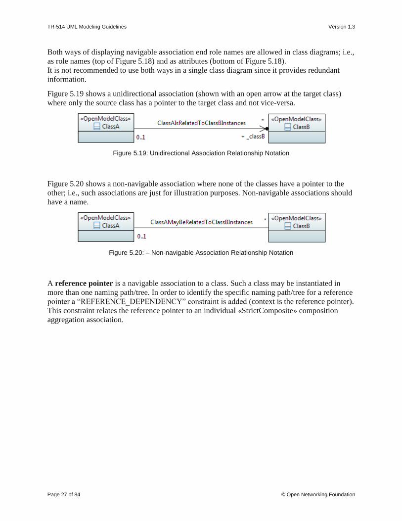
Figure 5.19 shows a unidirectional association (shown with an open arrow at the target class)
where only the source class has a pointer to the target class and not vice-versa.
Figure 5.19: Unidirectional Association Relationship Notation
Figure 5.20 shows a non-navigable association where none of the classes have a pointer to the
other; i.e., such associations are just for illustration purposes. Non-navigable associations should
have a name.
Figure 5.20: – Non-navigable Association Relationship Notation
A reference pointer is a navigable association to a class. Such a class may be instantiated in
more than one naming path/tree. In order to identify the specific naming path/tree for a reference
pointer a “REFERENCE_DEPENDENCY” constraint is added (context is the reference pointer).
This constraint relates the reference pointer to an individual «StrictComposite» composition
aggregation association.

TR-514 UML Modeling Guidelines Version 1.3
Page 28 of 84 © Open Networking Foundation
Figure 5.21: – Reference Pointer to Classes with more than one Composition Aggregation Association Relationship Notation
A shared aggregation is a special type of association in which objects are assembled or
configured together to create a more complex object. Aggregation protects the integrity of an
assembly of objects by defining a single point of coordination called aggregate, in the object that
represents the assembly.
Figure 5.22: Aggregation Association Relationship Notation
A «LifecycleAggregate» aggregation is a shared aggregation which indicates a lifecycle
dependency between a grouping instance and its shared part instances; similar to the lifecycle
dependency of a composite aggregation.
This option is intended to be used only when the shared part object class has another stronger
lifecycle dependency (such as composition).
The multiplicity at the grouping side of the «LifecycleAggregate» relationship defines the mode:
single = exclusive mode, one or more = shared mode.
In exclusive mode, a shared part object instance must not be aggregated by more than one

TR-514 UML Modeling Guidelines Version 1.3
Page 29 of 84 © Open Networking Foundation
grouping instance via a «LifecycleAggregate» relationship.
In shared mode, a shared part object instance can be aggregated by more than one grouping
instance via a «LifecycleAggregate» relationship.
A shared part instance has to have at all times a containing composite instance AND a single (in
case of exclusive mode) or at least one (in case of shared mode) aggregating grouping instance.
Figure 5.23: «LifecycleAggregate» Aggregation Association Relationship Notation
Note: The «LifecycleAggregate» association cannot define the operational behavior which can
be seen from containing or contained class point of view. Four deletion policies can be
distinguished:
1. Deletion of containing OwningClass instance deletes all contained instances
2. Deletion of containing GroupingClass instance deletes aggregated instances
3. Containing OwningClass instance must not be deleted as long as contained instances
exist
4. Containing GroupingClass instance must not be deleted as long as contained instances
exist
See also usage example in section 7.7.
A composite aggregation association is a strong form of aggregation that requires a part instance
be included in at most one composite at a time. If a composite is deleted, all of its parts are
deleted as well; i.e., the lifecycle of all instances of ClassB related to an instance classA is tied to
the lifecycle of the classA instance. It is possible for the part instance to move from one parent
instance to another.

TR-514 UML Modeling Guidelines Version 1.3
Page 30 of 84 © Open Networking Foundation
Note: In the example below, ClassA also names ClassB instances; defined by the «Names»
stereotype.
Figure 5.24: Composite Aggregation Association Relationship Notation
A «StrictComposite» aggregation association is a composite aggregation where it is NOT
possible for the part instance to move from one parent instance to another (as is allowed in
regular compositions).
Figure 5.25: «StrictComposite» Aggregation Association Relationship Notation
An «ExtendedComposite» aggregation is a more restrictive form of a «StrictComposite»
aggregation where the extending classes will never be explicitly instantiated (i.e., are abstract),
but that the attributes defined by the extending class will be transferred to the class being
extended at runtime, much like the UML Generalization relationship. In other words, the
extending classes are essentially carrying attributes of the extended class in a grouping-pack. The
extending class has a multiplicity of 0..1.
Figure 5.26: «ExtendedComposite» Aggregation Association Relationship Notation
Association classes are not used.
5.4.2.2 Generalization Notation
A generalization indicates a relationship in which one class (the child) inherits from another class
(the parent). A generalization relationship may be conditional, identified by the «Cond»
stereotype.

TR-514 UML Modeling Guidelines Version 1.3
Page 31 of 84 © Open Networking Foundation
Figure 5.27: Generalization Relationship Notation (normal, conditional and example)
5.4.2.3 Dependency Notation
“A dependency is a relationship that signifies that a single or a set of model elements requires
other model elements for their specification or implementation. This means that the complete
semantics of the depending elements is either semantically or structurally dependent on the
definition of the supplier element(s)...“, an extract from [2].
A dependency relationship may define naming identified by the «NamedBy» stereotype.
Figure 5.28: Dependency Relationship Notation (normal and naming)
The usage dependency relationship along with the relationship name indicates the dependency
between an Interface and the object class the Interface is working on.

TR-514 UML Modeling Guidelines Version 1.3
Page 32 of 84 © Open Networking Foundation
Figure 5.29: Usage Dependency Notation
The abstraction dependency relationship can be annotated by the «Specify» stereotype to
indicate that the definition of the more abstract entity class in the abstraction relationship is
augmented by the "specification" class definition at runtime. See also the definition in section
5.4.3 below.
Figure 5.30: Abstraction Dependency Notation
«Specify» annotated abstraction relationships must be started from abstract classes.
It is also possible to condition the «Specify» abstraction relationship based on attribute values.
The conditioning attribute and its value(s) is defined in a {constraint} attached to the «Specify»
relationship. It has to be set at creation time and needs to be invariant. The condition could also
be a list of attributes (e.g., attribute1 + attribute2) and need not be in the object class to be
specified.

TR-514 UML Modeling Guidelines Version 1.3
Page 33 of 84 © Open Networking Foundation
Figure 5.31: Conditional «Specify» Abstraction Relationship Example
The realization dependency relationship indicates the relationship between a base class and it’s
realizing class.
The realization dependency relationship along with the «PruneAndRefactor» stereotype
indicates the relationship between a Base Model class/relationship and the
cloned/pruned/refactored Purpose Specific Model class/relationship.
Figure 5.32: Realization Dependency Notation
5.4.3 Relationship Properties
A relationship has the following properties:
• Name
Follows Upper Camel Case (UCC) style and is unique across all relationship names
defined in the whole model.
The format for associations is "<Class1Name><VerbPhrase><Class2Name>" where the
verb phrase creates a sequence that is readable and meaningful. In case of a long class
name, it is also allowed to use a short form of the name.

TR-514 UML Modeling Guidelines Version 1.3
Page 34 of 84 © Open Networking Foundation
• Documentation
Contains a short definition. The documentation is carried in the “Applied comments”
field in Papyrus; i.e., the “Owned comments” field shall not be used. The complete
documentation should be written in a single comment; i.e., at most one “Applied
comment”.
• Abstract (only association)
Associations which are just for explanation to the reader of the model are defined as
"abstract" (Note: In Papyrus, the abstract property is defined in the Advanced tab of the
Properties view). Their ends are not navigable and have no role names. Abstract
associations shall not be taken into account in a protocol specific implementation.
• Type
The following types are used:
• simple association,
• composition association,
• aggregation association,
• generalization,
• dependency,
• usage dependency,
• abstraction dependency,
• realization dependency.
• Role Name (only associations)
Follows Lower Camel Case (LCC) style with an underscore “_” prefix and identifies the
role that the object plays at this end (Member End) of the association.
Only navigable Member Ends have role names and follow the definitions made for
attributes in clause 5.3.
• Role Type (only association)
The type of the role is fixed to the class attached to the association end. Therefore, it is
important to define the type as “passed by reference” or “passed by value”. Pointer and
shared aggregation associations are per default passed by reference (i.e., contain only the
reference (name, identifier, address) to the referred instance(s) when being transferred
across the interface). The composition aggregation, «StrictComposite» and
«ExtendedComposite» associations are always passed by value (i.e., contain the complete
information of the instance(s) when being transferred across the interface).
Note: The Owner of a navigable Member End has to be the Classifier to become an
attribute in the class.
Figure 5.33: Owner of a navigable Member End

TR-514 UML Modeling Guidelines Version 1.3
Page 35 of 84 © Open Networking Foundation
• Role Multiplicity (only association)
Identifies the number of class instances that can participate in an instance of the
association.
• Additional optional properties:
• «Names» (only association)
The «Names» stereotype identifies that the association is used to define the naming.
• «NamedBy» (only dependency)
The «NamedBy» stereotype identifies that a dependency relationship is used to define
naming.
• «Cond» (all relationships)
The «Cond» stereotype identifies that the relationship is conditional. The condition is
also provided.
• «StrictComposite» (only association)
The «StrictComposite» stereotype can only be applied to associations with a
composite end (i.e., composite aggregation association). It means that the content of
the “parts” classes is part of the “composed” parent class and has no opportunity for
independent lifecycle. In this case although an instance of the "parts" classes can be
created and deleted anytime, it has to be in the context of the "composed" parent
class. In other words, the parent class instance has to exist and it is NOT possible for
the "part" instance to move from one parent instance to another (allowed in regular
composition).
Whereas in an association with a composite end that is not «StrictComposite» the
composed class is a part that has a restricted independent lifecycle. In this case an
instance of the composed class can be created and deleted in the context of the parent
class and should be represented as a separate instance from the parent in an
implementation. This is especially true where there is a recursive composition. It is
possible that in some cases the composed instance could move from one parent to
another so long as it exists with one parent only at all points of the transaction. This
move is not meaningful for a class associated via a «StrictComposite» association.
• «ExtendedComposite» (only association)
The «ExtendedComposite» stereotype indicates a more restrictive form of
"StrictComposite" where the "extending" classes will never be explicitly instantiated,
but that the attributes defined by the “extending” class will be transferred to the class
being “extended” at runtime, much like the UML “Generalization” relationship (with
the difference, that in the «ExtendedComposite» case the “extended” class is
instantiated and in the “Generalization” case the subclass is instantiated). In other
words, the "extending” classes are strictly composed, they are essentially carrying
attributes of the “extended” class in a grouping-pack and often referred to as "_Pacs".
• «LifecycleAggregate» (only shared aggregation association)
A «LifecycleAggregate» aggregation is a shared aggregation which indicates a
lifecycle dependency between a grouping instance and its shared part instances;
similar to the lifecycle dependency of a composite aggregation.
The «LifecycleAggregate» aggregation can only be used jointly with another stronger
lifecycle dependency (such as composition) to the same part instance; i.e., must not
be used alone.

TR-514 UML Modeling Guidelines Version 1.3
Page 36 of 84 © Open Networking Foundation
• «PruneAndRefactor» (only realization)
The «PruneAndRefactor»stereotype identifies that a realization association is used to
identify pruning and refactoring.
• «Specify» (only abstraction)
The «Specify» stereotype is applied on the UML “Abstraction” relationship to
indicate that the definition of the more abstract entity class in the abstraction
relationship is augmented by the "specification" class definition at runtime.
Furthermore, there is a potential for an entity class definition to be augmented by
more than one "specification" class definitions. In other words, one of the
specification classes adds-to and expands the runtime-definition of the entity class.
This also implies that the entity class cannot be aware of the existence of specification
classes at design time. Since the “Specify” relationship is defined to support runtime
code/schema generation and dependency injection, a stereotype-property “target” is
defined to point to the actual node being augmented within the object/instance
schema. The "target" value should be in the following format:
[/<ModelName>:<ClassName>]+:<AttributeName>.
Example: TopologyContext in TapiTopology augments Context in TapiCommon
target=/TapiCommon:Context:_context
Example: NodeEdgePointLpSpec in TapiOdu specifies LayerProtocol definition for
NodeEdgePoint in TapiTopology
target=/TapiTopology:TopologyContext/TapiTopology:Topology/TapiTopology:Nod
e/Tapi:Topology:NodeEdgePoint/_layerProtocol.

TR-514 UML Modeling Guidelines Version 1.3
Page 37 of 84 © Open Networking Foundation
Figure 5.34: Potential Annotations for Associations
The following UML defined role/attribute properties are not used:
• Visibility (default = public)
5.5 Interfaces
5.5.1 Description
An «Interface» is used to group operations, i.e., models the dynamic part of the model.
Groupings of operations can be used to modularize the functionalities of the specification.
Note: Interfaces (and operations) may only be defined in the purpose-specific models of the
information model; see Figure 4.1.
5.5.2 «Interface» Notation
Interfaces are identified by the stereotype «Interface».

TR-514 UML Modeling Guidelines Version 1.3
Page 38 of 84 © Open Networking Foundation
Figure 5.35: Graphical Notation for «Interface»
«Interfaces» usually have name, attributes and operations compartments. The structural part and
the behavioral part of the model are decoupled. Therefore, the attributes compartment is not used
and always empty. It is also possible to hide the attributes compartment in the interface
diagrams.
Figure 5.36: Graphical Notation for «Interface» without Attributes Compartment
Note: The graphical notation of an «Interface» may show an empty operation compartment so as
to reduce clutter even if the «Interface» has operations.
5.5.3 «Interface» Properties
An «Interface» has the following properties:
• Name
Follows Upper Camel Case (UCC) style and is unique across all «Interface» names in the
model.
• Documentation
Contains a short definition. The documentation is carried in the “Applied comments”
field in Papyrus; i.e., the “Owned comments” field shall not be used. The complete
documentation should be written in a single comment; i.e., at most one “Applied
comment”.
• Superinterface(s)
Inheritance and multiple inheritance may be used.
• Abstract
Indicates if the «Interface» can be instantiated or is just used for inheritance.
• Additional properties are defined in the «OpenModelInterface» stereotype which extends
( ) by default (required) the «metaclass» Interface:

TR-514 UML Modeling Guidelines Version 1.3
Page 39 of 84 © Open Networking Foundation
Figure 5.37: «OpenModelInterface» Stereotype
• support
This property qualifies the support of the «Interface» at the management interface.
See definition in clause 5.10.
• condition
This property contains the condition for the condition-related support qualifiers.
The following UML defined interface properties are not used:
• Is leaf (default = false)
• Visibility (default = public)
5.6 Interface Operations
5.6.1 Description
Operations can be defined within an «Interface». An «Interface» shall have at least one
operation.
Note: Operations may only be defined in the purpose-specific models of the information model;
see Figure 4.1.
5.6.2 Operation Notation
Figure 5.38: Graphical Notation for «Interface» with Operations
5.6.3 Operation Properties
An operation has the following properties:

TR-514 UML Modeling Guidelines Version 1.3
Page 40 of 84 © Open Networking Foundation
• Name
Follows Lower Camel Case (LCC) style and is unique across all operation names defined
in the whole model.
• Documentation
Contains a short definition. The documentation is carried in the “Applied comments”
field in Papyrus; i.e., the “Owned comments” field shall not be used. The complete
documentation should be written in a single comment; i.e., at most one “Applied
comment”.
• Pre-condition(s)
This property defines the conditions that have to be true before the operation can be
started (i.e., if not true, the operation will not be started at all and a general “precondition
not met” error will be returned, i.e., exception is raised).
• Post-condition(s)
This property defines the state of the system after the operation has been executed (if
successful, or if not successful, or if partially successful).
Note that partially successful post-condition(s) can only be defined in case of non-atomic
operations.
Note that when an exception is raised, it should not be assumed that the post-condition(s)
are satisfied.
• Parameter(s)
See clause 5.7.
• Operation Exceptions
Lists the allowed exceptions for the operation.
The model uses predefined exceptions which are split in 2 types:
- generic exceptions which are associated to all operations by default
- common exceptions which needs to be explicitly associated to the operation.
Note: These exceptions are only relevant for a protocol neutral information model.
Further exceptions may be necessary for a protocol specific information model.
Generic exceptions:
• Internal Error: The server has an internal error.
• Unable to Comply: The server cannot perform the operation. Use Cases may identify
specific conditions that will result in this exception.
• Comm Loss: The server is unable to communicate with an underlying system or
resource, and such communication is required to complete the operation.
• Invalid Input: The operation contains an input parameter that is syntactically incorrect
or identifies an object of the wrong type or is out of range (as defined in the model or
because of server limitation).
• Not Implemented: The entire operation is not supported by the server or the operation
with the specified input parameters is not supported.
• Access Denied: The client does not have access rights to request the given operation.
Common exceptions:

TR-514 UML Modeling Guidelines Version 1.3
Page 41 of 84 © Open Networking Foundation
• Entity Not Found: Is thrown to indicate that at least one of the specified entities does
not exist.
• Object In Use: The object identified in the operation is currently in use.
• Capacity Exceeded: The operation will result in resources being created or activated
beyond the capacity supported by the server.
• Not In Valid State: The state of the specified object is such that the server cannot
perform the operation. In other words, the environment or the application is not in an
appropriate state for the requested operation.
• Duplicate: Is thrown if an entity cannot be created because an object with the same
identifier/name already exists.
• Additional properties are defined in the «OpenModelOperation» stereotype which
extends
( ) by default (required) the «metaclass» Operation:
Figure 5.39: «OpenModelOperation» Stereotype
• isOperationIdempotent (Boolean) (obsolete)
This property defines if the operation is idempotent (true) or not (false).
Example: When an operation is going to create an instance which does already exist,
an idempotent operation would return success and a non-idempotent operation would
return an exception.
• isAtomic (Boolean) (obsolete)
This property identifies if the operation is best effort or is successful / not successful
as a whole.
• support
This property qualifies the support of the operation at the management interface. See
definition in clause 5.10.
• condition
This property contains the condition for the condition-related support qualifiers.
The following UML defined operation properties are not used:
• Is leaf (default = false)
• Is query (default = false)
• Is static (default = false)

TR-514 UML Modeling Guidelines Version 1.3
Page 42 of 84 © Open Networking Foundation
5.7 Operation Parameters
5.7.1 Description
Parameters define the input and output signals of an operation.
Note: Operations and their parameters may only be defined in the purpose-specific models of the
information model; see Figure 4.1.
5.7.2 Parameter Notation
The notation is:
<visibility> <direction> <parameter name> : <parameter type> [<multiplicity>] = <default
value>
Note: When no default is relevant or no default is defined, the “=” is not shown
Figure 5.40: Graphical Notation for «Interface» with Operations and Parameters
5.7.3 Parameter Properties
A parameter has the following properties:
• Name
Follows Lower Camel Case (LCC) style
• Documentation
Contains a short definition. The documentation is carried in the “Applied comments”
field in Papyrus; i.e., the “Owned comments” field shall not be used. The complete
documentation should be written in a single comment; i.e., at most one “Applied
comment”.
• Direction
Parameters can be defined as:
- input parameters
- output parameters
- in out parameters

TR-514 UML Modeling Guidelines Version 1.3
Page 43 of 84 © Open Networking Foundation
• Type
Refers to a data type.
Note that a list of parameters can also be combined in a complex data type.
• Default Value
Defines the value that the parameter has in case the value is not provided. If it is
mandatory to provide a value, the default value is set to NA.
• Is Ordered
Defines for a multi-valued parameter that the order of the values is significant.
• Multiplicity
Defines the number of values the parameter can simultaneously have.
• Additional properties are defined in the «OpenModelParameter» stereotype which
extends
( ) by default ({required}) the «metaclass» Parameter:
Figure 5.41: «OpenModelParameter» Stereotype
• valueRange
Identifies the allowed values for the parameter.
• support
This property qualifies the support of the parameter at the management interface. See
definition in clause 5.10.
• condition
This property contains the condition for the condition-related support qualifiers.
• Other properties:
• PassedByReference
This property is only relevant in interface related (purpose-specific) models and shall
only be applied to parameters that have an object class defined as their type; i.e., on a
case by case basis.
The property defines if the attribute contains only the reference (name, identifier,
address) to the referred instance(s) when being transferred across the interface.
Otherwise the parameter contains the complete information of the instance(s) when
being transferred across the interface.
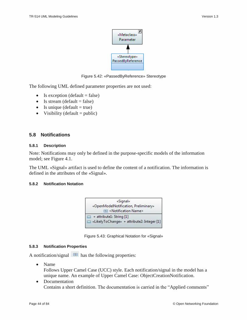
TR-514 UML Modeling Guidelines Version 1.3
Page 44 of 84 © Open Networking Foundation
Figure 5.42: «PassedByReference» Stereotype
The following UML defined parameter properties are not used:
• Is exception (default = false)
• Is stream (default = false)
• Is unique (default = true)
• Visibility (default = public)
5.8 Notifications
5.8.1 Description
Note: Notifications may only be defined in the purpose-specific models of the information
model; see Figure 4.1.
The UML «Signal» artifact is used to define the content of a notification. The information is
defined in the attributes of the «Signal».
5.8.2 Notification Notation
Figure 5.43: Graphical Notation for «Signal»
5.8.3 Notification Properties
A notification/signal has the following properties:
• Name
Follows Upper Camel Case (UCC) style. Each notification/signal in the model has a
unique name. An example of Upper Camel Case: ObjectCreationNotification.
• Documentation
Contains a short definition. The documentation is carried in the “Applied comments”

TR-514 UML Modeling Guidelines Version 1.3
Page 45 of 84 © Open Networking Foundation
field in Papyrus; i.e., the “Owned comments” field shall not be used. The complete
documentation should be written in a single comment; i.e., at most one “Applied
comment”.
• Superclass(es)
Inheritance and multiple inheritance may be used to deal with shared properties.
• Abstract
Indicates if the notification/signal can be instantiated or is just used for inheritance.
• Additional properties are defined in the «OpenModelNotification» stereotype which
extends ( ) by default (required) the «metaclass» Signal:
Figure 5.44: «OpenModelNotification» Stereotype
• triggerConditionList
This property contains the triggering conditions that cause the notification. Create one
element in the trigger condition list per trigger as shown on the figure below:
Figure 5.45: Notification Trigger Condition List
Use the green + button to create a new element in the list:
Figure 5.46: Trigger Condition List Pop-up

TR-514 UML Modeling Guidelines Version 1.3
Page 46 of 84 © Open Networking Foundation
• support
This property qualifies the support of the notification/signal at the management
interface. See definition in clause 5.10.
• condition
This property contains the condition for the condition-related support qualifiers.
The following UML defined class properties are not used:
• Is leaf (default = false)
• Visibility (default = public)
5.9 Data Types
5.9.1 Description
Data Types are used as type definitions of attributes and parameters.
Data Types are divided into 3 categories:
• (Complex) Data Types (further structured; e.g., Host which combines ipAddress and domainName)
• Primitive Types (not further structured; e.g., Integer, MAC address).
• Enumerations
5.9.2 Type Notation
Figure 5.47: Graphical Notation for «DataType»
Note: Default values may not be shown in all class diagrams.
Figure 5.48: Graphical Notation for «Enumeration»
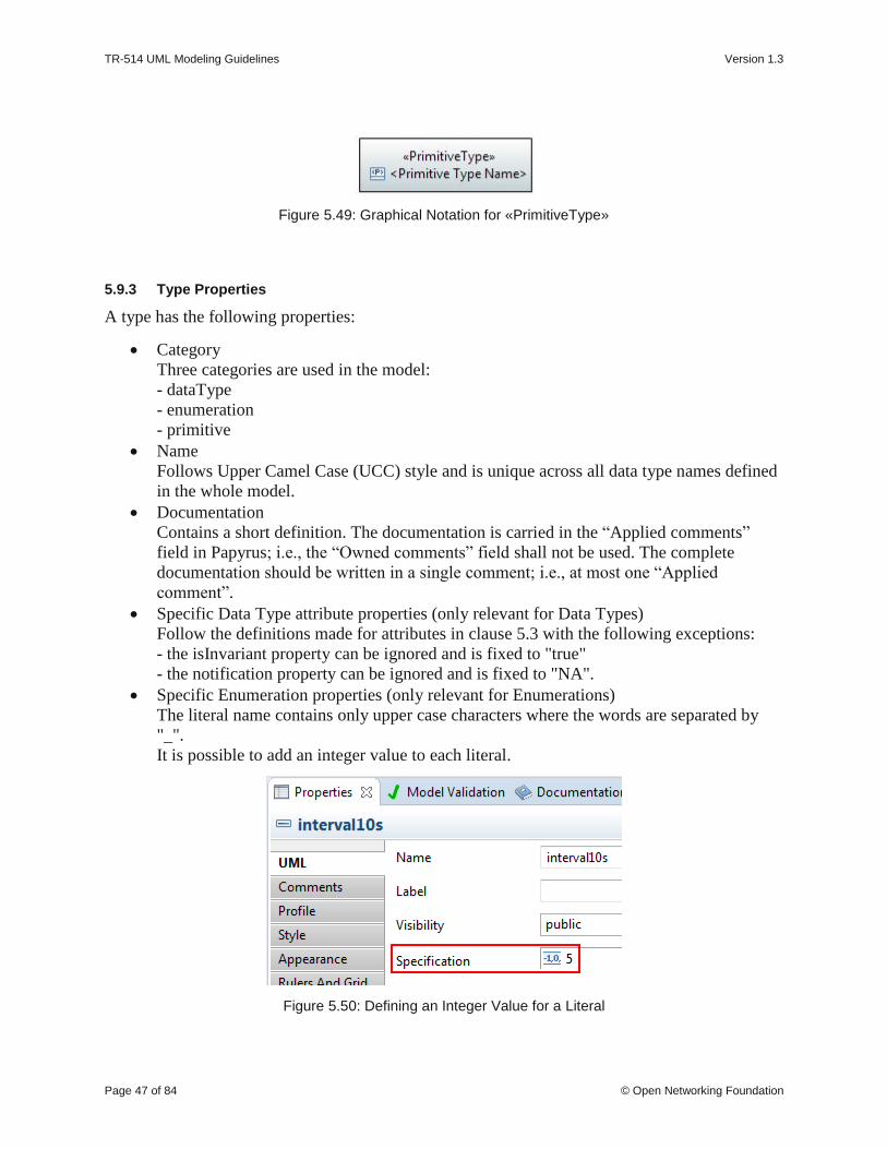
TR-514 UML Modeling Guidelines Version 1.3
Page 47 of 84 © Open Networking Foundation
Figure 5.49: Graphical Notation for «PrimitiveType»
5.9.3 Type Properties
A type has the following properties:
• Category
Three categories are used in the model:
- dataType
- enumeration
- primitive
• Name
Follows Upper Camel Case (UCC) style and is unique across all data type names defined
in the whole model.
• Documentation
Contains a short definition. The documentation is carried in the “Applied comments”
field in Papyrus; i.e., the “Owned comments” field shall not be used. The complete
documentation should be written in a single comment; i.e., at most one “Applied
comment”.
• Specific Data Type attribute properties (only relevant for Data Types)
Follow the definitions made for attributes in clause 5.3 with the following exceptions:
- the isInvariant property can be ignored and is fixed to "true"
- the notification property can be ignored and is fixed to "NA".
• Specific Enumeration properties (only relevant for Enumerations)
The literal name contains only upper case characters where the words are separated by
"_".
It is possible to add an integer value to each literal.
Figure 5.50: Defining an Integer Value for a Literal

TR-514 UML Modeling Guidelines Version 1.3
Page 48 of 84 © Open Networking Foundation
The property “isLeaf” is used to define if the list of literals is fixed or is open for
enhancement in future releases. isLeaf = true → fixed literal list; isLeaf = false → literal
list may be enhanced.
• Additional properties
• «Choice» (obsolete)
This stereotype identifies a data type as a choice between different alternatives; see
also clause 7.5.
• «Exception»
This stereotype defines a data type used for an operation exception.
• «Bits» (preliminary solution 2)
This optional stereotype defines a data type used for defining a bit set. Each bit is
defined as an attribute of the data type; see also Figure 5.15.
Figure 5.51: Potential Annotations for Data Types
The following UML defined attribute properties are not used:
• Is abstract (default = false)
• Is leaf (default = false)
5.9.4 UML Primitive Types
Papyrus already provides the following UML primitive types:
Figure 5.52: Primitive Types provided by Papyrus
Notes:
The “Unlimited Natural” Primitive data type shall not be used.
Papyrus also exposes the internal Eclipse eCore primitives which are not to be used in models.
The UML Primitive Types can be further restricted by the annotation of the following properties
contained in the OpenModelAttribute stereotype (see definitions in clause 5.3.3):

TR-514 UML Modeling Guidelines Version 1.3
Page 49 of 84 © Open Networking Foundation
• bitLength
• unsigned
• encoding
• counter
For example: «UNSIGNED, LENGTH_8_BIT» Integer or «HexEncoded» String.
Note that common floating point types ‘float’ and ‘double’ are represented using the profile as
below:
• Float (single-precision, 32-bit IEEE 754 floating point): «LENGTH_32_BIT»Real
• Double (double-precision, 64-bit IEEE 754 floating point): «LENGTH_64_BIT»Real.
5.9.5 Pre-defined Data Types
Additional common data types are defined in two separate model libraries which are imported to
every UML model. The CoreCommonDataTypes should be used for models before
pruning&refactoring and the ImplementationCommonDataTypes should be used for models after
pruning&refactoring.
Note that model projects should not create their own primitive types. Requests for new primitive
types should be made to the IISOMI team so they can be included in the standard Papyrus files
and then available to all modeling teams.
Similar data types are grouped together to ease the search of the adequate data type by the model
designer. The following groupings and containing data types are under discussion at the time of
publication of these guidelines.

TR-514 UML Modeling Guidelines Version 1.3
Page 50 of 84 © Open Networking Foundation
Figure 5.53: Common Data Types Grouping
Figure 5.54: Core and Implementation Common Data Types

TR-514 UML Modeling Guidelines Version 1.3
Page 51 of 84 © Open Networking Foundation
Address related Types
• IpAddress
• Ipv4Address
• Ipv6Address
• IpAddressNoZone
• Ipv4AddressNoZone
• Ipv6AddressNoZone
• Ipv4Prefix
• Ipv6Prefix
• IpPrefix
• MacAddress
Date and Time related Types
• DateTime
Domain Name and URI related Types
• DomainName
• Uri
Identifier related Types
• ObjectIdentifier
• ObjectIdentifier128
Protocol Field related Types
• Dscp

TR-514 UML Modeling Guidelines Version 1.3
Page 52 of 84 © Open Networking Foundation
• IpVersion
• IpV6FlowLabel
• PortNumber
String related Types
• DottedQuad
• Uuid
5.10 Qualifiers and Conditions
This clause defines the qualifiers applicable for model elements specified in this document, e.g.,
the «OpenModelClass» (see clause 5.2.3), and the «OpenModelAttribute» (see clause 5.3.3). The
qualifications are M, O, CM, CO and C. Their meanings are specified in this clause. This type of
qualifier is called Support Qualifier.
• Definition of M (Mandatory) qualification:
The model element shall be supported.
• Definition of O (Optional) qualification:
The model element may, but needs not to, be supported.
• Definition of CM (Conditional-Mandatory) qualification:
The model element shall be supported under certain conditions. If the specified
conditions are met then the model element shall be supported.
• Definition of CO (Conditional-Optional) qualification:
The model element may, but needs not to, be supported under certain conditions. If the
specified conditions are met then the model element may, but needs not to, be supported.
If the specified conditions are not met then the model element shall be supported.
• Definition of C (Conditional) qualification:
Used for model elements that have multiple constraints. Each constraint is worded as a
condition for one kind of support, such as mandatory support, optional support or "no
support". All constraints shall be related to the same kind of support. Specifically:
Each model element with C qualification shall have the corresponding multiple
constraints defined in the specification. If all specified constraints are met and are related
to mandatory, then the model element shall be supported. If all the specified constraints
are met and are related to optional, then the model element may, but needs not to, be
supported. If all the specified constraints are met and are related to "no support", then the
model element shall not be supported.
The condition property contains the condition for the condition-related support qualifiers (CM,
CO, C). Often different conditional UML artifacts share the same condition. It is therefore
recommended to group such conditions within a model based on the supported features. The
grouping is provided by the first line of the condition string which shall contain the name of the
group; i.e., all condition strings of the UML artifacts which share the same condition have the

TR-514 UML Modeling Guidelines Version 1.3
Page 53 of 84 © Open Networking Foundation
same text in their first line. The second and further lines may contain an explanation of the
condition.
Figure 5.55: Conditional Class Example
Figure 5.56: Conditional Attributes Example
5.11 Use Cases
Use case diagrams define actors in a system and the defined behavior over a specific interface.
The actor is the entity that is invoking the behavior over the interface. In the diagram below, the
actor is a stick figure representing a business application that is given a “name” which shall be
specified in Upper Camel Case (UCC). The use cases, or the defined behavior invoked over an
interface, are defined in the “ovals” and specified in their “names” in Upper Camel Case (UCC)
also. The tabular format which defines the input, output, description, etc. of a use case is only
found in the Interface Profile Specification and is not present in the UML model.
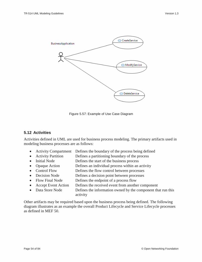
TR-514 UML Modeling Guidelines Version 1.3
Page 54 of 84 © Open Networking Foundation
Figure 5.57: Example of Use Case Diagram
5.12 Activities
Activities defined in UML are used for business process modeling. The primary artifacts used in
modeling business processes are as follows:
• Activity Compartment Defines the boundary of the process being defined
• Activity Partition Defines a partitioning boundary of the process
• Initial Node Defines the start of the business process
• Opaque Action Defines an individual process within an activity
• Control Flow Defines the flow control between processes
• Decision Node Defines a decision point between processes
• Flow Final Node Defines the endpoint of a process flow
• Accept Event Action Defines the received event from another component
• Data Store Node Defines the information owned by the component that run this
activity
Other artifacts may be required based upon the business process being defined. The following
diagram illustrates as an example the overall Product Lifecycle and Service Lifecycle processes
as defined in MEF 50.

TR-514 UML Modeling Guidelines Version 1.3
Page 55 of 84 © Open Networking Foundation
Figure 5.58: Example Business Process Modeling
5.13 State Machines
State machines define state transitions and triggers that shall occur for the transitions to take
place. The primary artifacts used in modeling state machines are as follows:
• State Machine Compartment Defines the boundary of the state machine
• Region Defines a region within a state machine
• Initial State Defines the initial state
• Transition Defines the trigger for a state transition to occur
• State Defines a given state within the state machine
• Final State Defines the final, or end state
Other artifacts may be required based upon the state machine being defined.
As an example, see the state machine of the Lifecycle Stereotypes in Figure 6.9.
6 UML Profile Definitions
6.1 UML Profile Structure
The additional properties for the UML Model artifacts and UML Profile artifacts are defined in
UML Profiles. The structure is defined in the figure below:

TR-514 UML Modeling Guidelines Version 1.3
Page 56 of 84 © Open Networking Foundation
Figure 6.1: UML Profile Structure
6.2 Additional Properties for the General Information on the UML Model
Clause 4.4 describes the additional general information on a UML Model. These properties are
defined in the OpenModelStatement stereotype as shown in Figure 6.2 below.
Figure 6.2: OpenModelStatement Required «Stereotype»
Details are provided in Table 6.1.
6.3 Additional Common Properties for individual UML Model artifacts
Clause 5 has already described the additional properties for each UML Model artifact. All
defined stereotypes are shown as an overview in Figure 6.3 and Figure 6.4 below.
Apply Profileto Model
Prune&Refactor
ProfileLifecycle_Profile
OpenModel_Profile
InterfaceModel_Profile
Apply mandatory profile/style sheet
Apply optional profile
Style Sheets Apply Style Sheetto Class Diagrams

TR-514 UML Modeling Guidelines Version 1.3
Page 57 of 84 © Open Networking Foundation
Figure 6.3: OpenModel Profile: Required «Stereotypes»

TR-514 UML Modeling Guidelines Version 1.3
Page 58 of 84 © Open Networking Foundation
Figure 6.4: OpenModel Profile: Optional «Stereotypes»
Table 6.1: OpenModel Profile: Complex «Stereotypes»
Stereotype Name of
property Type Allowed values Default value
Associated to
metaclass
OpenModel
Statement
namespace String urn Model
organization String

TR-514 UML Modeling Guidelines Version 1.3
Page 59 of 84 © Open Networking Foundation
Stereotype Name of
property Type Allowed values Default value
Associated to
metaclass
contact Contact
projectWeb String URL
projectEmail String Email address
editorName String
editorEmail String Email address
description String
copyright String
license String
revision Revision
date String yyyy-mm-dd
version String
description String
changeLog String URL
additionalChanges String
reference String
OpenModel
Class support Enumeration
MANDATORY
OPTIONAL
CONDITIONAL_
MANDATORY
CONDITIONAL_
OPTIONAL
CONDITIONAL
MANDATORY Class
condition String
OpenModel
Attribute
partOfObjectKey Integer 0,1,2,3,... 0
Property
uniqueSet Integer 0,1,2,3,...
isInvariant Boolean true/false false
valueRange String NA
unsigned Boolean true/false false
counter Counter
NA
COUNTER
GAUGE
ZERO_COUNTE
R
NA
unit String
support Enumeration
MANDATORY
OPTIONAL
CONDITIONAL_
MANDATORY
CONDITIONAL_
OPTIONAL
CONDITIONAL
MANDATORY
condition String

TR-514 UML Modeling Guidelines Version 1.3
Page 60 of 84 © Open Networking Foundation
Stereotype Name of
property Type Allowed values Default value
Associated to
metaclass
OpenModel
Interface
support Enumeration
MANDATORY
OPTIONAL
CONDITIONAL_
MANDATORY
CONDITIONAL_
OPTIONAL
CONDITIONAL
MANDATORY Interface
condition String
OpenModel
Operation
isOperationIdempotent
(obsolete) Boolean true/false false
Operation
isAtomic (obsolete) Boolean true/false false
support Enumeration
MANDATORY
OPTIONAL
CONDITIONAL_
MANDATORY
CONDITIONAL_
OPTIONAL
CONDITIONAL
MANDATORY
condition String
OpenModel
Parameter
valueRange String NA
Parameter support Enumeration
MANDATORY
OPTIONAL
CONDITIONAL_
MANDATORY
CONDITIONAL_
OPTIONAL
CONDITIONAL
MANDATORY
condition String
OpenModel
Notification
triggerConditionList String
Signal support Enumeration
MANDATORY
OPTIONAL
CONDITIONAL_
MANDATORY
CONDITIONAL_
OPTIONAL
CONDITIONAL
MANDATORY
condition String
Cond condition String Relationship
Reference reference String Element
Specify target String Abstraction

TR-514 UML Modeling Guidelines Version 1.3
Page 61 of 84 © Open Networking Foundation
6.4 Additional Interface related Properties for individual UML Model artifacts
Clause 5 has already described the additional properties for each UML Model artifact. All
defined stereotypes related to an interface model are shown as an overview in Figure 6.5 and
Figure 6.6 below.
Figure 6.5: OpenInterfaceModel Profile: Required «Stereotypes»

TR-514 UML Modeling Guidelines Version 1.3
Page 62 of 84 © Open Networking Foundation
Figure 6.6: OpenInterfaceModel Profile: Optional «Stereotypes»
Table 6.2: OpenInterfaceModel Profile: Complex «Stereotypes»
Stereotype Name of
property Type Allowed values
Default
value
Associated to
metaclass
OpenInterfaceModel
Class (obsolete)
objectCreation
Notification Enumeration
NO
YES
NA
NA
Class
objectDeletion
Notification Enumeration
NO
YES
NA
NA
OpenInterfaceModel
Attribute
writeAllowed Enumeration
CREATE_ONLY
UPDATE_ONLY
CREATE_AND_UPDATE WRITE_NOT_ALLOWED
CREATE
_AND_ UPDATE
Property
attributeValueChange
Notification
(obsolete)
Enumeration
NO
YES
NA
NA
bitLength BitLength
NA
LENGTH_8_BIT
LENGTH_16_BIT
LENGTH_32_BIT
LENGTH_64_BIT
NA
encoding Encoding
NA
BASE_64
HEX
OCTET
NA
bitsDefinition BitDefinition
name String
position Integer 0

TR-514 UML Modeling Guidelines Version 1.3
Page 63 of 84 © Open Networking Foundation
Stereotype Name of
property Type Allowed values
Default
value
Associated to
metaclass
description String
support Enumeration
MANDATORY
OPTIONAL
CONDITIONAL_ MANDATORY
CONDITIONAL_
OPTIONAL CONDITIONAL
MANDATORY
condition String
RootElement
name String
Class multiplicity String <lower bound>..
<upper bound> 1..1
description String
6.5 Additional Properties for all UML artifacts
6.5.1 Description
This clause defines the additional properties that may be associated to
• all UML Model artifacts and
• all UML Profile artifacts.
6.5.2 LifecycleState Property
All UML Model artifacts (packages, classes, attributes, interfaces, operations, parameters, data
types, associations and generalizations) may be appended with one of the following lifecycle
states:
• Deprecated
This stereotype indicates that the entity may become obsolete in the near future. It may
still be used in new implementation.
The entity should be kept in this state for at least one further release. The team has to
decide on a case by case basis when to move it to Obsolete.
• Experimental
This stereotype indicates that the entity is at a very early stage of development and will
almost certainly change. The entity is NOT mature enough to be used in implementation.
• Faulty
This stereotype indicates that the entity should not be used in new implementation and
that attempts should be made to remove it from existing implementation as there is a
problem with the entity. An update to the model with corrections will be released.
• LikelyToChange
This stereotype indicates that although the entity may be mature, work in the area has
indicated that change will be necessary (e.g., there are new insights in the area or there is

TR-514 UML Modeling Guidelines Version 1.3
Page 64 of 84 © Open Networking Foundation
now perceived benefit to be had from further rationalization). The entity can still be used
in implementation but with caution.
• Mature
This stereotype indicates that the entity is fully developed and can be used in
implementations without any constraints.
• Obsolete
This stereotype indicates that the entity should not be used in new implementation and
that attempts should be made to remove it from existing implementation.
The entity should be kept in the model at least for one further release. The team has to
decide on a case by case basis when to remove it from the model.
• Preliminary
This stereotype indicates that the entity is at a relatively early stage of development and is
likely to change but is mature enough to be used in implementation.
Rules:
One and only one lifecycle state has to be associated to every UML artifact.
It is recommended that every new UML artifact is initially annotated with the “Experimental”
lifecycle stereotype.

TR-514 UML Modeling Guidelines Version 1.3
Page 65 of 84 © Open Networking Foundation
Figure 6.7: Lifecycle «Stereotypes»
6.5.3 Profile LifecycleState Property
All UML Profile artifacts (stereotypes and properties) may be appended with one of the
following lifecycle states:
• DeprecatedProfileEntity
This stereotype indicates that the profile entity may become obsolete in the near future. It
may still be used in new implementation.
The profile entity should be kept in this state for at least one further release. The team has
to decide on a case by case basis when to move it to ObsoleteProfileEntity.
• ExperimentalProfileEntity
This stereotype indicates that the profile entity is at a very early stage of development and
will almost certainly change. The entity is NOT mature enough to be used in
implementation.
TR-514 UML Modeling Guidelines Version 1.3
Page 66 of 84 © Open Networking Foundation
• FaultyProfileEntity
This stereotype indicates that the profile entity should not be used in new implementation
and that attempts should be made to remove it from existing implementation as there is a
problem with the entity. An update to the model with corrections will be released.
• LikelyToChangeProfileEntity
This stereotype indicates that although the profile entity may be mature, work in the area
has indicated that change will be necessary (e.g., there are new insights in the area or
there is now perceived benefit to be had from further rationalization). The entity can still
be used in implementation but with caution.
• MatureProfileEntity
This stereotype indicates that the profile entity is fully developed and can be used in
implementations without any constraints.
• ObsoleteProfileEntity
This stereotype indicates that the profile entity should not be used in new implementation
and that attempts should be made to remove it from existing implementation.
• PreliminaryProfileEntity
This stereotype indicates that the profile entity is at a relatively early stage of
development and is likely to change but is mature enough to be used in implementation.
Rules:
One and only one profile lifecycle state has to be associated to every UML profile artifact.
It is recommended that every new UML profile artifact is initially annotated with the
“Experimental” lifecycle stereotype.

TR-514 UML Modeling Guidelines Version 1.3
Page 67 of 84 © Open Networking Foundation
Figure 6.8: Profile Lifecycle «Stereotypes»
The following state machine diagram shows the defined state transitions for both, the lifecycle
and the profile lifecycle stereotypes.

TR-514 UML Modeling Guidelines Version 1.3
Page 68 of 84 © Open Networking Foundation
Figure 6.9: Lifecycle and ProfileLifecycle LifecycleState State Machine
6.5.4 Reference Property
A reference can be defined for all UML artifacts. This is an optional property which contains a
reference upon which the artifact is based. A reference to a standard is preferred.
The reference property is defined in the Reference stereotype and extent the Element Metaclass.

TR-514 UML Modeling Guidelines Version 1.3
Page 69 of 84 © Open Networking Foundation
Figure 6.10: Reference «Stereotype»
6.5.5 Example Property
This is an optional property which can be defined for all UML artifacts
It is defined as a stereotype and indicates that the entity is NOT to be used in implementation and
is in the model simply to assist in the understanding of the model (e.g., a specialization of a
generalized class where the generalized class is to be used as is and the specialization is simply
offered to more easily illustrate an application of the generalized class).
Figure 6.11: Example «Stereotype»
7 Recommended Modeling Patterns
7.1 File Naming Conventions
tba
7.2 Model Structure
7.2.1 Generic Model Structure
Figure 7.1 shows a generic Information Model containing a core model and various sub-models
A, B, C structured by packages:

TR-514 UML Modeling Guidelines Version 1.3
Page 70 of 84 © Open Networking Foundation
Figure 7.1: Core Model and SubModels
Note:
Figure 7.1 shows only the schematic structure of the core and submodels as necessary for these
guidelines.
Each Model can be optionally organized into multiple submodels. Each Model or each of its
constituent submodels is further divided – at the bottom level of the hierarchy – into packages
containing associations, diagrams, imports, object classes, rules and type definitions. Submodels
may contain in addition packages for (UML-) interfaces (and their operations) and notifications.
7.2.2 Model Structure
The Information Model is structured into a Common Information Model and additional Specific
Views which are based on the Core Model. Specific models may also be added by other SDOs.
A Core Modeling team (with members from many SDOs) defines and maintains the generic
functions in the Core Model.

TR-514 UML Modeling Guidelines Version 1.3
Page 71 of 84 © Open Networking Foundation
Figure 7.2: Model Structure (snapshot)
In order to reduce clutter, the UML artefacts are grouped in pre-defined packages instead of
having all kinds of the various artefacts mashed up at the same level. This provides a human
friendly structure for the model. This structure accelerates the manual search for specific kinds of
artefacts.
Note: Not all pre-defined packages need to be established in a particular model instance.
Additional packages can be added when needed. Figure 7.3 shows the pre-defined packages at
the bottom level of the CoreNetworkModel.
Figure 7.3: Pre-defined Packages at the Bottom Level of each UML Model (Example)
7.3 Flexible Attribute Assignment to Classes
Since it is not possible to add attributes once an instance has been created, it is necessary to
differentiate case (a) where attributes are assembled before the instance is created, and case (b)
where further attributes (functions) are added after the instance is created.

TR-514 UML Modeling Guidelines Version 1.3
Page 72 of 84 © Open Networking Foundation
For case (a), attributes are grouped in classes called “Pacs” and are associated to the base class
using a conditional composition association (see clause 7.4 below).
An example for (a) is a specific LTP instance which has specific Pacs associated, based on the
functions that this LTP supports. Once the LTP is created, it is no longer possible to add further
attributes or remove attributes.
→ Instances are (automatically) created as an assembly of the base object plus a list of Pacs
(depending on the supported functionality).
For case (b), attributes are grouped in “normal” classes and are associated to the base class using
a composition association.
An example for (b) is a specific, already existing LTP instance which will be configured to do
performance monitoring (PM). In this case an additional PM instance (created on the basis of the
corresponding class (i.e., not Pac)) is separately instantiated and associated to the already
existing LTP. Note that it is also possible to remove the PM instance from the LTP afterwards
without impacting the life cycle of the base LTP instance.
→ Instances are created on an explicit request and associated to already existing instances
(depending on the requested additional functionality).
Figure 7.4: Flexible Attribute Assignment to Classes
7.4 Use of Conditional Packages
Conditional packages are used to enhance (core) classes / interfaces with additional attributes /
operations on a conditional basis. The attributes / operations are defined in special classes called
packages.

TR-514 UML Modeling Guidelines Version 1.3
Page 73 of 84 © Open Networking Foundation
Figure 7.5: Enhancing Classes Using Conditional Packages
Package names follow the same rules as defined for classes; i.e., UCC.
The role name of the navigable end pointing to the package follows the same rules as defined for
role names in section 5.4.3; i.e., LCC with an “_” prefix.
7.5 Use of XOR
7.5.1 Description
The UML Constraint artefact is used to model “Exclusive Or” (xor) restrictions between a set of
associations. Only one of the associations is active in the instantiated model at given point in
time. One end of all related associations need to be assigned to a common artefact (e.g., object
class, data type) which is the «context» of the Constraint.
The xor choice can either be defined directly attached to the containing class/data type (see
Choice3Choice in Figure 7.9) or indirectly by attaching the choice to a separate data type (see
Choice1DataType in Figure 7.9) which makes it usable in many places of the model.
The default choice can be defined by adding the Boolean typed default value “true” to the default
navigable attribute (see Choice1DataType in Figure 7.9).
7.5.2 Examples
The figures below shows various examples on how the {xor} constraint can be used.

TR-514 UML Modeling Guidelines Version 1.3
Page 74 of 84 © Open Networking Foundation
Figure 7.6: {xor} Alternative Example
Figure 7.7: {xor} Probable Cause Type Example

TR-514 UML Modeling Guidelines Version 1.3
Page 75 of 84 © Open Networking Foundation
Figure 7.8: {xor} Parent / Child Example

TR-514 UML Modeling Guidelines Version 1.3
Page 76 of 84 © Open Networking Foundation
Figure 7.9: Multi Level {xor} Example
7.5.3 Name style
The name of the {xor} constraint is written in UCC and appended by “Choice”.

TR-514 UML Modeling Guidelines Version 1.3
Page 77 of 84 © Open Networking Foundation
7.5.4 «Choice» (Obsolete)
7.5.4.1 Description
The «Choice» stereotype represents one of a set of classes (when used as an information model
element) or one of a set of data types (when used as an operations model element).
This stereotype property, e.g., one out of a set of possible alternatives, is identical to the {xor}
constraint (see 7.5).
7.5.4.2 Example
Sometimes the specific kind of class cannot be determined at model specification time. In order
to support such scenario, the specification is done by listing all possible classes.
The following diagram lists 3 possible classes. It also shows a « Choice, OpenModelClass,
InformationObjectClass» named SubstituteObjectClass. This scenario indicates that only one of
the three classes named Alternative1ObjectClass, Alternative2ObjectClass,
Alternative3ObjectClass shall be realized.
The «Choice» stereotype represents one of a set of classes when used as an information model
element.
Figure 7.10: Information Model Element Example Using «Choice» Notation
Sometimes the specific kind of data type cannot be determined at model specification time. In
order to support such scenario, the specification is done by listing all possible data types.
The following diagram lists 2 possible data types. It also shows a «Choice» named
ProbableCause. This scenario indicates that only one of the two «DataType» named
IntegerProbableCause, StringProbableCause shall be realized.
The «Choice» stereotype represents one of a set of data types when used as an operations model
element.

TR-514 UML Modeling Guidelines Version 1.3
Page 78 of 84 © Open Networking Foundation
Figure 7.11: Operations Model Element Example Using «Choice» Notation
Sometimes models distinguish between sink/source/bidirectional termination points. A generic
class which comprises these three specific classes can be modeled using the «Choice» stereotype.
Figure 7.12: Sink/Source/Bidirectional Termination Points Example Using «Choice» Notation
7.5.4.3 Name style
For «Choice» name, use the same style as «OpenModelClass» (see 5.2.3).
7.6 Proxy Class Modeling

TR-514 UML Modeling Guidelines Version 1.3
Page 79 of 84 © Open Networking Foundation
There are cases where an attribute or parameter may contain different kinds of classes. This
would require an attribute/parameter per kind of class. In order to reduce the number of
attributes/parameters it is recommended to define a proxy class and let a single
attribute/parameter point to this class. The different kinds of classes shall be inherited from the
proxy class. All real subclasses inheriting from the abstract superclass (proxy) shall have the
same object key.
Figure 7.13: Proxy Class Modeling Example
7.7 «LifecycleAggregate» Aggregation Usage
This section explains the impact of the «LifecycleAggregate» association based on a model
example, a corresponding instance diagram and the lifecycle dependency when grouping
instances are deleted.

TR-514 UML Modeling Guidelines Version 1.3
Page 80 of 84 © Open Networking Foundation
Figure 7.14: Usage Example for «LifecycleAggregate» Aggregation Association

TR-514 UML Modeling Guidelines Version 1.3
Page 81 of 84 © Open Networking Foundation
OwningClass instance
SharedPartClass instance
4
3
GroupingClassAinstance1
GroupingClassBinstance1
GroupingClassBinstance2
8
7
65
9
11
12
GroupingClassAinstance2
1314 15
SharedPartClass instance not allowed in exclusive mode
10
12
Figure 7.15: Instance Example for «LifecycleAggregate» Aggregation Association
The example model in Figure 7.14 and the corresponding instance diagram in Figure 7.15 define
the following behavior when grouping instances are deleted:
1. Deletion of OwningClass instance deletes all GroupingClass and SharedPartClass
instances
2. Deletion of GroupingClassA instance 2 deletes no SharedPartClass instances
3. Deletion of GroupingClassA instance 1 deletes GroupingClassA instance 2 but no
SharedPartClass instances
In exclusive mode (SharedPartClass instances 10 and 12 are not allowed):
4. Deletion of GroupingClassB instance 1 deletes SharedPartClass instances 3, 4 and 9
5. Deletion of GroupingClassB instance 2 deletes SharedPartClass instances 5, 6, 11 and 13
In shared mode (SharedPartClass instances 10 and 12 are allowed):
6. Deletion of GroupingClassB instance 1 deletes SharedPartClass instances 3, 4 and 9
7. Deletion of GroupingClassB instance 2 deletes SharedPartClass instances 5, 6, 11 and 13

TR-514 UML Modeling Guidelines Version 1.3
Page 82 of 84 © Open Networking Foundation
8. Deletion of GroupingClassB instance 1 deletes 3, 4 and 9; and when GroupingClassB
instance 2 is deleted afterwards, then SharedPartClass instances 5, 6, 10, 11, 12 and 13
are deleted.
7.8 Diagram Guidelines
7.8.1 Generic Diagram Guidelines
Classes and their relationships shall be presented in class diagrams.
Interfaces and their operations shall be presented in class diagrams.
Only applied optional stereotypes should be made visible in class diagrams.
If complex stereotypes need to be made visible in class diagrams, then they should be shown in a
comment.
It is recommended to create:
• An overview class diagram containing all classes related to a specific management area:
- The class name compartment should contain the location of the class definition (e.g.
"Qualified Name").
The class attributes should show the "Signature" (see clause 7.3.45 of [2] for the
signature definition).
• A separate inheritance class diagram in case the overview diagram would be
overcrowded when showing the inheritance structure (Inheritance Class Diagram).
• A class diagram containing the user defined data types (Type Definitions Diagram).
• Additional class diagrams to show specific parts of the specification in detail.
• State diagrams for complex state attributes.
• State transition diagrams for attributes with defined value transitions.
• Activity diagrams for operations with high complexity.
7.8.2 Using Colors
Using colors for the model artifacts has the benefit of distinguishing the types of the artifacts.
For example, color the artifacts that are imported from other models or which are new in this
release.
Further recommendations are to be provided.
7.8.3 Style Sheets
The graphic depiction of the class diagrams can be aligned using style sheets. These guidelines
define the following constraints:
• Mandatory stereotypes (e.g., «OpenInterfaceModelClass», «OpenModelClass»,
«OpenModelAttribute», …) should not be shown.
Note: Stereotypes which are specifically added – like e.g., «RootElement» – must be

TR-514 UML Modeling Guidelines Version 1.3
Page 83 of 84 © Open Networking Foundation
explicitly shown in the object class structure.
• Classes should not show the "nestedclassifiers" and "operations" compartments.
• Interfaces should not show the "nestedclassifiers" and "attributes" compartments.
• Data Types should not show the "operations" compartment.
• Primitive Types should not show any compartments.
• Attributes should only show name, type, multiplicity and defaultValue.
• Attributes should not show the stereotypes «OpenModelAttribute» and
«OpenInterfaceModelAttribute».
The use of the ClassDiagramStyleSheet.css style sheet implements these requirements:
ClassDiagramStyleSheet.css
The latest version of the style sheet can be downloaded from here:
https://github.com/OpenNetworkingFoundation/EAGLE-Open-Model-Profile-and-
Tools/tree/ToolChain/UmlProfiles
8 Main Changes between Releases
8.1 Summary of main changes between version 1.0 and 1.1
The following guidelines have been added:
• isAtomic property on operations
• «OpenModelNotification» stereotype
• realization association along with the «PruneAndRefactor» stereotype
• «Deprecated» lifecycle stereotype.
The requirement to use “Ref” and “List” in attribute/parameter/role names has been deprecated
since the “Ref” property is already defined by the «PassedByReference» property and the “List”
property is already defined by the multiplicity property.
The Guidelines are no longer ONF dependent; i.e, they can now be used as is by other SDOs.
8.2 Summary of main changes between version 1.1 and 1.2
• Document moved to Open Source SDN
• Using UML Version 2.5 as basis.
• Further properties added to OpenModelAttribute stereotype:
o partOfObjectKey
o bitLength

TR-514 UML Modeling Guidelines Version 1.3
Page 84 of 84 © Open Networking Foundation
o unsigned
o encoding
o counter.
• Table 5.2 on attribute property dependencies added.
• Clauses on Use Cases (5.11), Activities (5.12) and State Machines (5.13) added.
• Clause 7.8.3 on style sheets for class diagrams added.
• Clause 7.6 on proxy class modeling added.
• Element metaclass extended by an optional reference stereotype.
8.3 Summary of main changes between version 1.2 and 1.3
• Adapted to ETSI drafting rules.
• Interface model related properties separated from OpenModelProfile and new
OpenInterfaceModelProfile added in new section 6.4.
• Attribute setability properties added in new section 5.3.4 and attribute property readOnly
no longer used.
• uniqueSet property added in section 5.3.3.
• Metaclass Diagram (Figure 5.17) of used relationships added.
• usage and abstraction dependency relationships added in section 5.4.2.
• «ExtendedComposite», «StrictComposite», «LifecycleAggregate» and «Specify»
stereotypes added.
• IsLeaf property added to class and attribute.
• Stereotype «PassedByReference» moved from OpenInterfaceModelProfile to
OpenModelProfile.
• Properties settingTime and settingActor removed from OpenModelAttribute stereotype.
• Scope of «Cond» stereotype enhanced; it extends now the relationship metaclass.
• Core and Implementation CommonDataTypes added.
• New sections 4.4 and 6.2 on “General Information on the UML Model” added.
• Bits encoding defined in section 5.3.3.
• Reference pointer dependency added in section 5.4.2.1.
• Made «Choice» stereotype obsolete.
• Made «OpenInterfaceModelClass» stereotype obsolete.
• Made OpenModelOperation::isOperationIdempotent property obsolete.
• Made OpenModelOperation::isAtomic property obsolete.
• Made OpenInterfaceModelAttribute::attributeValueChangeNotification property
obsolete.
Top Related