


Languages
Pages
Legal


MAKING MODERN LIVING POSSIBLE
Technical Information
Orbital MotorsType OMP, OMR and OMH
powersolutions.danfoss.com

Revision history Table of revisions
Date Changed Rev
November 2014 Converted to Danfoss layout - DITA CMS DA
Nov 2012 Planetary Gears deleted CF
Sep 2011 Typo CE
Sep 2010 New back cover CD
Mar 2010 Japan location CC
Jun 2007 Major revision with new lit-number (minus OMEW, will be prepared separately CA
Mar 2006 Small updates B
Technical Information Orbital Motors Type OMP, OMR and OMH
2 520L0262 • Rev DA • November 2014

A Wide Range of Hydraulics MotorsA Wide Range of Hydraulic Motors............................................................................................................................................ 6Survey of Literature with Technical Data on Danfoss Hydraulic Motors......................................................................7Speed, Torque and Output........................................................................................................................................................... 8
VersionsVersions................................................................................................................................................................................................9
Features available (options).................................................................................................................................................... 9
Code NumbersCode Numbers................................................................................................................................................................................ 10
Technical DataTechnical data for OMP with 25 mm and 1 in cylindrical shaft..................................................................................... 11Technical data for OMP with 1 in splined and 28.5 mm tapered shaft.......................................................................12Technical data for OMP with 32 mm cylindrical shaft...................................................................................................... 13
Technical Data - Max. Permissible Shaft Seal PressureOMP with HIGH Pressure Shaft Seal (HPS)............................................................................................................................ 15OMP with Standard Shaft Seal...................................................................................................................................................15
Technical DataPressure Drop in Motor................................................................................................................................................................17Oil flow in drain line...................................................................................................................................................................... 17Direction of Shaft Rotation......................................................................................................................................................... 17Permissible Shaft Load for OMP N........................................................................................................................................... 18Permissible Shaft Load for OMPW with Slide Bearings.................................................................................................... 19Permissible Shaft Load for OMPW N with Needle Bearing............................................................................................. 19
Function DiagramsFunction Diagrams........................................................................................................................................................................ 21
OMP 60 under preparation .................................................................................................................................................. 22OMP 110 under preparation.................................................................................................................................................23
Shaft VersionShaft Version....................................................................................................................................................................................25
Port Thread VersionsPort Thread Versions.....................................................................................................................................................................27Manifold Mount..............................................................................................................................................................................27
Dimensions - European VersionDimensions.......................................................................................................................................................................................28
Dimensions - US VersionDimensions.......................................................................................................................................................................................32
Dimensions - European VersionDimensions.......................................................................................................................................................................................33
Dimensions - US VersionDimensions.......................................................................................................................................................................................35
Dimensions - European VersionDimensions.......................................................................................................................................................................................37
VersionsVersions............................................................................................................................................................................................. 39
Features available (options)..................................................................................................................................................40
Code NumbersCode Numbers................................................................................................................................................................................ 41
Technical DataTechnical data for OMR with 25 mm and 1 in cylindrical shaft..................................................................................... 42Technical data for OMR with 1 in splined and 28.5 mm tapered shaft.......................................................................42Technical data for OMR with 32 mm , 1 ¼ in cylindrical shaft and 35 mm, 1 ¼ in tapered shaft......................43
Technical Information Orbital Motors Type OMP, OMR and OMH
Contents
520L0262 • Rev DA • November 2014 3

Technical Data for Parking Brake Motor OMR F, OMR NF and OMRW NF................................................................. 44Function............................................................................................................................................................................................ 44
Technical Data - Max. Permissible Shaft Seal PressureOMR with High Pressure Shaft Seal (HPS)............................................................................................................................. 46OMR with Standard Shaft Seal.................................................................................................................................................. 46
Technical DataPressure Drop in Motor................................................................................................................................................................48Oil flow in drain line...................................................................................................................................................................... 48Direction of Shaft Rotation......................................................................................................................................................... 48Permissible Shaft Loads for OMR..............................................................................................................................................48Permissible Shaft Load for OMR N and OMR NF with Needle Bearings..................................................................... 49Permissible Shaft Load for OMRW N and OMRW NF with Needle Bearings............................................................. 50
Function DiagramsFunction Diagrams........................................................................................................................................................................ 51
Shaft VersionShaft Version....................................................................................................................................................................................54
Port Thread VersionsPort Thread Versions.....................................................................................................................................................................58Manifold Mount..............................................................................................................................................................................58
Dimensions-European versionDimensions.......................................................................................................................................................................................59
Dimension-US VersionDimensions.......................................................................................................................................................................................65
Dimensions-European VersionDimensions.......................................................................................................................................................................................67
Dimensions-US VersionDimensions.......................................................................................................................................................................................69
Dimensions-European VersionDimensions.......................................................................................................................................................................................71
Dimensions-US VersionDimensions.......................................................................................................................................................................................73
Dimensions-European VersionDimensions.......................................................................................................................................................................................75
Dimensions-US VersionDimensions.......................................................................................................................................................................................76
Dimensions-European VersionDimensions.......................................................................................................................................................................................77
Dimensions-US VersionDimensions.......................................................................................................................................................................................78
Dimensions-European VersionDimensions.......................................................................................................................................................................................79
VersionVersions............................................................................................................................................................................................. 81
Code NumbersCode Numbers................................................................................................................................................................................ 82
Technical DataTechnical data for OMH with 1 in SAE 6 B splined shaft.................................................................................................. 83Technical data for OMH with 32 mm and 1 1/4 in cylindrical shaft.............................................................................83Technical data for OMH with 35 mm cylindrical, 1 1/4 in splined and 35 mm tapered shaft............................ 84
Technical Information Orbital Motors Type OMP, OMR and OMH
Contents
4 520L0262 • Rev DA • November 2014

Max. Permissible Shaft Seal Pressure...................................................................................................................................... 85Pressure Drop in Motor................................................................................................................................................................86Oil Flow in Drain Line....................................................................................................................................................................86Direction of Shaft Rotation......................................................................................................................................................... 87Permissible Shaft Loads for OMH.............................................................................................................................................87
Function DiagramsFunction Diagrams........................................................................................................................................................................ 88
Shaft VersionShaft Version....................................................................................................................................................................................90
Technical DataPort Thread Versions.....................................................................................................................................................................93Manifold Mount..............................................................................................................................................................................94
Dimensions-European VersionDimensions.......................................................................................................................................................................................95
Dimensions-US VersionDimensions.......................................................................................................................................................................................96
Weight of motorsWeight of Motors........................................................................................................................................................................... 97
Technical Information Orbital Motors Type OMP, OMR and OMH
Contents
520L0262 • Rev DA • November 2014 5

A Wide Range of Hydraulic Motors
Danfoss is a world leader within production of low speed hydraulic motors with high torque. We can offermore than 3000 different hydraulic motors, categorised in types, variants and sizes (incl. different shaftversions).
The motors vary in size (rated displacement) from 8 cm3 [0.50 in3] to 800 cm3 [48.9 in3] per revolution.
Speeds range up to approx. 2500 min-1 (rpm) for the smallest type and up to approx
600 min-1 (rpm) for the largest type.
Maximum operating torques vary from 13 Nm [115 lbf·in] to 2700 Nm [24.000 lbf·in] (peak) and maximumoutputs are from 2.0 kW [2.7 hp] to 70 kW [95 hp].
Characteristic features:• Smooth running over the entire speed range
• Constant operating torque over a wide speed range
• High starting torque
• High return pressure without the use of drain line (High pressure shaft seal)
• High efficiency
• Long life under extreme operating conditions
• Robust and compact design
• High radial and axial bearing capacity
• For applications in both open and closed loop hydraulic systems
• Suitable for a wide variety of hydraulics fluids
The programme is characterised by technical features appealing to a large number of applications and apart of the programme is characterised by motors that can be adapted to a given application. Adaptionscomprise the following variants among others:
Technical Information Orbital Motors Type OMP, OMR and OMH
A Wide Range of Hydraulics Motors
6 520L0262 • Rev DA • November 2014
• Motors with corrosion resistant parts
• Wheel motors with recessed mounting flange
• OMP, OMR- motors with needle bearing
• OMR motor in low leakage version
• OMR motors in a super low leakage version
• Short motors without bearings
• Ultra short motors
• Motors with integrated positive holding brake
• Motors with integrated negative holding brake
• Motors with integrated flushing valve
• Motors with speed sensor
• Motors with tacho connection
• All motors are available with black finish paint
The Danfoss LSHT motors are used in the following application areas:• Construction equipment
• Agricultural equipment
• Material handling & Lifting equipment
• Forestry equipment
• Lawn and turf equipment
• Special purpose
• Machine tools and stationary equipment
• Marine equipment
Survey of Literature with Technical Data on Danfoss Hydraulic Motors
Detailed data on all Danfoss motors can be found in our motor catalogue, which is divided into 8individual subcatalogues:• General information on Danfoss hydraulic motors: function, use, selection of hydraulic motor,
hydraulic systems, etc.• Technical data on small motors: OML and OMM
• Technical data on medium sized motors: OMP, OMR and OMH
• Technical data on medium sized motors: DH and DS
• Technical data on medium sized motors: OMEW
• Technical data on large motors: OMS, OMT and OMV
• Technical data on large motors: TMK
• Technical data on large motors: TMT
• Technical data on large motors: TMVW
A general survey brochure on Danfoss hydraulic motors gives a quick motor reference based on power,torque, speed and capabilities.
Technical Information Orbital Motors Type OMP, OMR and OMH
A Wide Range of Hydraulics Motors
520L0262 • Rev DA • November 2014 7

Speed, Torque and Output
Max. speed, Max. torque, Max. output
1800
1600
1400
1200
1000
800
600
400
200
25 32 40 50 60 80 100
110
125
160
200
250
315
400 50 80 100
125
160
200
250
315
375
200
250
315
400
5003) 3) 3)2) 2) 2) 2) 2)1) 1) 1) 1)
25 32 40 50 60 80 100
110
125
160
200
250
315
400 50 80 100
125
160
200
250
315
375
200
250
315
400
5003) 3) 3)2) 2) 2) 2) 2)1) 1) 1) 1)
25 32 40 50 60 80 100
110
125
160
200
250
315
400 50 80 100
125
160
200
250
315
375
200
250
315
400
5003) 3) 3)2) 2) 2) 2) 2)1) 1) 1) 1)
min-1
(rpm)
151-1418.11
OMP OMR OMH
10000
9000
8000
7000
6000
5000
4000
3000
2000
1000
1100
1000
900
800
700
600
500
400
300
200
100
25
20
15
10
5
0
15
10
5
hp kW
Nmlbf• in
Peak value, Intermittend values, Continuous values
1. 1 1/4 in shaft
2. 1 1/4 in or 1 1/4 in tapered shaft
3. 1 1/4 in splined shaft
The bar diagrams above are useful for a quick selection of relevant motor size for the application. Thefinal motor size can be determined by using the function diagram for each motor size.• OMP and OMPW: see Function Diagrams on page 21• OMR and OMRW: see Function Diagrams on page 51• OMH: see Function Diagrams on page 88
The function diagrams are based on actual tests on a representative number of motors from ourproduction. The diagrams apply to a return pressure between 5 and 10 bar.
[75 and 150 psi] when using mineral based hydraulic oil with a viscosity of 35 mm2/s
[165 SUS] and a temperature of 50°C [120°F]. For further explanation concerning how to read and use thefunction diagrams, please consult the paragraph "Selection of motor size" in the technical informationGeneral Orbital Motors 520L0232 Rev. B.
Technical Information Orbital Motors Type OMP, OMR and OMH
A Wide Range of Hydraulics Motors
8 520L0262 • Rev DA • November 2014
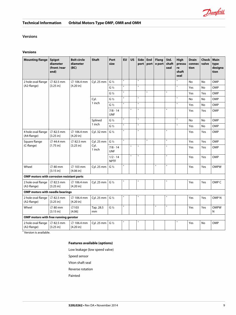
Versions
Mounting flange Spigotdiameter(front /rearend)
Bolt circlediameter(BC)
Shaft Portsize
EU US Sideport
Endport
Flange port
Std.shaftseal
Highpressureshaftseal
Drainconnection
Checkvalve
Maintypedesignation
2 hole oval flange(A2-flange)
∅ 82.5 mm[3.25 in]
∅ 106.4 mm[4.20 in]
Cyl. 25 mm G ½ * * * No No OMP
G ½ * * * Yes No OMP
G ½ * * * Yes Yes OMP
Cyl.1 inch
G ½ * * * No No OMP
G ½ * * * Yes No OMP
7/8 - 14UNF
* * * Yes Yes OMP
Splined1 inch
G ½ * * * No No OMP
G ½ * * * Yes No OMP
4 hole oval flange(A4-flange)
∅ 82.5 mm[3.25 in]
∅ 106.4 mm[4.20 in]
Cyl. 32 mm G ½ * * * Yes Yes OMP
Square flange(C-flange)
∅ 44.4 mm[1.75 in]
∅ 82.5 mm[3.25 in]
Cyl. 25 mmCyl.1 inch
G ½ * * * Yes Yes OMP
7/8 - 14UNF
* * * Yes Yes OMP
1/2 - 14NPTF
* * * Yes Yes OMP
Wheel ∅ 80 mm[3.15 in]
∅ 103 mm[4.06 in]
Cyl. 25 mm G ½ * * * Yes Yes OMPW
OMP motors with corrosion resistant parts
2 hole oval flange(A2-flange)
∅ 82.5 mm[3.25 in]
∅ 106.4 mm[4.20 in]
Cyl. 25 mm G ½ * * * Yes Yes OMP C
OMP motors with needle bearings
2 hole oval flange(A2-flange)
∅ 82.5 mm[3.25 in]
∅ 106.4 mm[4.20 in]
Cyl. 25 mm G ½ * * * Yes Yes OMP N
Wheel ∅ 80 mm[3.15 in]
∅103[4.06]
Tap. 28.5mm
G ½ * * * Yes Yes OMPWN
OMP motors with free running gerotor
2 hole oval flange(A2-flange)
∅ 82.5 mm[3.25 in]
∅ 106.4 mm[4.20 in]
Cyl. 25 mm G ½ * * * Yes No OMP
* Version is available.
Features available (options)
Low leakage (low speed valve)
Speed sensor
Viton shaft seal
Reverse rotation
Painted
Technical Information Orbital Motors Type OMP, OMR and OMH
Versions
520L0262 • Rev DA • November 2014 9

Code Numbers
Codenumbers
Displacement [cm3]
25 32 40 50 60 80 100 110 125 160 200 250 315 400
151- 0340 0341 0342 0310 0319 0311 0312 - 0313 0314 0315 0316 0317 0318
151- 0640 0641 0642 0610 - 0611 0612 0646 0613 0614 0615 0616 0617 0618
151- - - - 5191 - 5192 5193 - 5194 5195 5196 5197 5198 5199
151- - - - 0300 - 0301 0302 - 0303 0304 0305 0306 0307 0308
151- - - - 0600 - 0601 0602 - 0603 0604 0605 0606 0607 0608
151- 7080 7081 7082 7041 - 7042 7043 - 7044* 7045 7046 7047 7048 7049
151- - - - 0330 - 0331 0332 - 0333 0334 0335 0336 0337 0338
151- - - - 0630 - 0631 0632 - 0633 0634 0635 0636 0637 0638
151- - 5010 - 5001 - 5002 5003 - 5004 5005 5006 5007 5008 5009
151- - - - 5211 - 5212 5213 - 5214 5215 5216 5217 5218 5219
151- - - - 7061 - 7062 7063 - 5174 7065 7066 7067 7068 7069
151- - - - 7021 - 7022 7023 - 7024 7025 7026 7027 7028 7029
151- - - - 7101 - 7102 7103 - 7104 7105 7106 7107 7108 7109
OMP motors with corrosion resistant parts
151- - - - 1208 - 1209 1210 - 1217 1211 1212 1213 1214 1215
OMP motors with needle bearings
151- - - - 5311 - 5312 5313 - - 5315 5316 - 5318 -
151- - - - 5301 - 5302 5303 - 5304 5305 5306 5307 5308 5309
OMP motors with free running gerotor
151- - - - - - - 0622 - - 0624 0625 - 0627 -
20 20 21 21 22 22 23 23 24 24 25 25 26 26
* Motor painted black
Ordering
Add the four digit prefix “151-” to the four digit numbers from the chart for complete code number.
Example:
151-0305 for an OMP 200 with A2 flange, cyl. 1 in shaft, port size G 1/2 and high pressure shaft seal.
Orders will not be accepted without the four digit prefix.
Technical Information Orbital Motors Type OMP, OMR and OMH
Code Numbers
10 520L0262 • Rev DA • November 2014

Technical data for OMP with 25 mm and 1 in cylindrical shaft
Type OMP OMP OMP OMP OMP OMP OMP
Motor size 25 32 40 50 60 80 100
Geometric displacement cm3
[inch]25.0[1.53]
32.0[1.96]
40.0[2.45]
48.6[2.97]
59.1[3.61]
77.8[4.76]
97.3[5.95]
Max. speed min-1 cont. 1600 1560 1500 1230 1000 770 615
[rpm] int.1) 1800 1720 1750 1540 1250 960 770
Max. torque N•m[lbf•in]
cont. 33[290]
43[380]
52[460]
93[820]
115[1020]
150[1330]
190[1680]
int.1) 47[420]
61[540]
74[660]
120[1060]
140[1240]
190[1680]
230[2040]
peak2) 67[590]
86[760]
107[950]
140[1240]
180[1590]
220[1950]
270[2390]
Max. output kW[hp]
cont. 4.5[6.0
5.8[7.8]
7.0[9.4]
10.0[13.4]
10.0[13.4]
10.0[13.4]
11.0[14.8]
int.1) 6.1[8.2]
7.8[10.5]
10.6[14.2]
12.0[16.1]
12.0[16.1]
12.0[16.1]
13.0[17.4]
Max. pressure drop bar[psi]
cont. 100[1450]
100[1450]
100[1450]
140[2030]
140[2030]
140[2030]
140[2030]
int.1) 140[2030]
140[2030]
140[2030]
175[2540]
175[2540]
175[2540]
175[2540]
peak2) 225[3260]
225[3260]
225[3260]
225[3260]
225[3260]
225[3260]
225[3260]
Max. oil flow l/min[US gal/min]
cont. 40[10.6]
50[13.2]
60[15.9]
60[15.9]
60[15.9]
60[15.9]
60[15.9]
int.1) 45[11.9]
55[14.5]
70[18.5]
75[19.8]
75[19.8]
75[19.8]
75[19.8]
Max. starting pressure with barunloaded shaft [psi]
standard 10[145]
10[145]
10[145]
10[145]
10[145]
10[145]
10[145]
free runninggerotor
- - - - - - 2[29]
Min starting torque at max. press drop cont.N•m [lbf•in]
30[270]
40[350]
45[400]
80[710]
100[885]
135[1200]
170[1510]
at max. press.drop int.1)
N•m [lbf•in]40[350]
55[490]
63[560]
100[890]
120[1060]
170[1510]
210[1860]
1) Intermittent operation: the permissible values may occur for max. 10% of every minute.2) Peak load: the permissible values may occur for max. 1% of every minute.
Type OMP OMP OMP OMP OMP OMP OMP
Motor size 110 125 160 200 250 315 400
Geometric displacement cm3
[inch]112.5[6.87]
125.0[7.65]
155.7[9.53]
194.6[11.91]
242.3[14.83]
306.1[18.73]
389.2[23.82]
Max. speed min-1 cont. 535 480 385 310 250 195 155
[rpm] int1) 670 600 480 385 310 245 190
Technical Information Orbital Motors Type OMP, OMR and OMH
Technical Data
520L0262 • Rev DA • November 2014 11

Type OMP OMP OMP OMP OMP OMP OMP
Motor size 110 125 160 200 250 315 400
Max. torque N•m[lbf•in]
cont. 215[1900]
240[2120]
300[2660]
300[2660]
300[2660]
300[2660]
300[2660]
int.1) 260[2300]
290[2570]
370[3280]
380[3360]
410[3630]
390[3450]
420[3720]
peak2) 320[2830]
370[3280]
430[3810]
540[4780]
550[4870]
600[5310]
600[5310]
Max. output kW[hp]
cont. 10[13.4]
10[13.4]
10[13.4]
8.0[10.7]
6.0[8.1]
5.0[6.7]
4.0[5.4]
int.1) 12.0[16.1]
12.0[16.1]
12.0[16.1]
11.0[14.8]
9.0[12.1]
7.0[9.4]
6.0[8.1]
Max. pressure drop bar[psi]
cont. 140[2030]
140[2030]
140[2030]
115[1670]
90[1310]
75[1090]
60[870]
int1) 175[2540]
175[2540]
175[2540]
150[2180]
125[1810]
100[1450]
80[1160]
peak2) 225[3260]
225[3260]
225[3260]
225[3260]
180[2610]
160[2320]
130[1890]
Max. oil flow l/min[US gal/min]
cont. 60[15.9]
60[15.9]
60[15.9]
60[15.9]
60[15.9]
60[15.9]
60[15.9]
int.1) 75[19.8]
75[19.8]
75[19.8]
75[19.8]
75[19.8]
75[19.8]
75[19.8]
Max. starting pressure with barunloaded shaft [psi]
standard 10[145]
9[130]
7[100]
5[75]
5[75]
5[75]
5[75]
free runninggerotor
- 2[29]
2[29]
2[29]
- - -
Min starting torque at max. press drop cont.N•m [lbf•in]
190[1680]
210[1860]
280[2480]
270[2390]
280[2480]
280[2480]
280[2480]
at max. press.drop int.1)
N•m [lbf•in]240[2120]
270[2390]
350[3100]
360[3190]
390[3450]
370[3280]
400[3540]
1) Intermittent operation: the permissible values may occur for max. 10% of every minute.2) Peak load: the permissible values may occur for max. 1% of every minute.
Technical data for OMP with 1 in splined and 28.5 mm tapered shaft
Type OMP OMP OMP OMP OMP OMP OMP OMP OMP
Motor size 50 80 100 125 160 200 250 315 400
Geometric displacement cm3
[inch]48.6[2.97]
77.8[4.76]
97.3[5.95]
125.0[7.65]
155.7[9.53]
194.6[11.91]
242.3[14.83]
306.1[18.73]
389.2[23.82]
Max. speed min-1 cont. 1230 770 615 480 385 310 250 195 155
[rpm] int.1) 1540 960 770 600 480 385 310 245 190
Max. torque N•m[lbf•in]
cont. 93[820]
150[1330]
190[1680]
240[2120]
300[2660]
360[3190]
360[3190]
360[3190]
360[3190]
int.1) 120[1060]
190[1680]
230[2040]
290[2570]
370[3280]
450[3980]
460[4070]
470[4160]
460[4070]
peak2) 140[1240]
220[1950]
270[2390]
370[3280]
430[3810]
540[4780]
550[4870]
540[4780]
560[4960]
Technical Information Orbital Motors Type OMP, OMR and OMH
Technical Data
12 520L0262 • Rev DA • November 2014

Type OMP OMP OMP OMP OMP OMP OMP OMP OMP
Motor size 50 80 100 125 160 200 250 315 400
Max. output kW[hp]
cont. 10.0[13.4]
10.0[13.4]
11.0[14.8]
10.0[13.4]
10.0[13.4]
10.0[13.4]
8.0[10.7]
6.0[8.0]
5.0[6.7]
int.1) 12.0[16.1]
12.0[16.1]
13[17.4]
12.0[16.1]
12.0[16.1]
12.0[16.1]
10.5[14.1]
7.5[10.1]
6.0[8.0]
Max. pressure drop bar[psi]
cont. 140[2030]
140[2030]
140[2030]
140[2030]
140[2030]
140[2030]
105[1520]
90[1310]
70[1020]
int1) 175[2540]
175[2540]
175[2540]
175[2540]
175[2540]
175[2540]
140[2030]
120[1740]
90[1310]
peak2) 225[3260]
225[3260]
225[3260]
225[3260]
225[3260]
225[3260]
180[2610]
160[2320]
130[1890]
Max. oil flow l/min[US gal/min]
cont. 60[15.9]
60[15.9]
60[15.9]
60[15.9]
60[15.9]
60[15.9]
60[15.9]
60[15.9]
60[15.9]
int.1) 75[19.8]
75[19.8]
75[19.8]
75[19.8]
75[19.8]
75[19.8]
75[19.8]
75[19.8]
75[19.8]
Max. starting pressure withunloaded shaft
bar[psi]
10[145]
10[145]
10[145]
9[130]
7[100]
5[75]
5[75]
5[75]
5[75]
Min starting torque at max. press drop cont.N•m [lbf•in]
80[710]
135[1200]
170[1510]
210[1860]
280[2480]
340[3010]
330[2920]
340[3010]
345[3050]
at max. press.drop int.1)
N•m [lbf•in]100[890]
170[1510]
210[1860]
270[2390]
350[3100]
420[3720]
440[3890]
450[3980]
425[3760]
1) Intermittent operation: the permissible values may occur for max. 10% of every minute.2) Peak load: the permissible values may occur for max. 1% of every minute.
Technical data for OMP with 32 mm cylindrical shaft
Type OMP OMP OMP OMP OMP OMP OMP OMP OMP
Motor size 50 80 100 125 160 200 250 315 400
Geometric displacement cm3
[inch]48.6[2.97]
77.8[4.76]
97.3[5.95]
125.0[7.65]
155.7[9.53]
194.6[11.91]
242.3[14.83]
306.1[18.73]
389.2[23.82]
Max. speed min-1 cont. 1230 770 615 480 385 310 250 195 155
[rpm] int.1) 1540 960 770 600 480 385 310 245 190
Max. torque N•m[lbf•in]
cont. 93[820]
150[1330]
190[1680]
240[2120]
300[2660]
360[3190]
460[4070]
470[4160]
490[4340]
int.1) 120[1060]
190[1680]
230[2040]
290[2570]
370[3280]
450[3980]
570[5050]
620[5490]
630[580]
peak2) 140[1240]
220[1950]
270[2390]
370[3280]
430[3810]
540[4780]
670[5930]
820[7260]
840[7440]
Max. output kW[hp]
cont. 10.0[13.4]
10.0[13.4]
11.0[14.8]
10.0[13.4]
10.0[13.4]
10.0[13.4]
9.5[12.7]
7.5[10.1]
6.5[8.7]
int.1) 12.0[16.1]
12.0[16.1]
13.0[17.4]
12.0[16.1]
12.0[16.1]
12.0[16.1]
12.0[16.1]
9.0[12.1]
7.5[10.1]
Max. pressure drop bar[psi]
cont. 140[2030]
140[2030]
140[2030]
140[2030]
140[2030]
140[2030]
140[2030]
120[1740]
95[1380]
int.1) 175[2540]
175[2540]
175[2540]
175[2540]
175[2540]
175[2540]
175[2540]
160[2320]
125[1810]
peak2) 225[3260]
225[3260]
225[3260]
225[3260]
225[3260]
225[3260]
225[3260]
225[3260]
180[2610]
Technical Information Orbital Motors Type OMP, OMR and OMH
Technical Data
520L0262 • Rev DA • November 2014 13

Type OMP OMP OMP OMP OMP OMP OMP OMP OMP
Motor size 50 80 100 125 160 200 250 315 400
Max. oil flow l/min[US gal/min]
cont. 60[15.9]
60[15.9]
60[15.9]
60[15.9]
60[15.9]
60[15.9]
60[15.9]
60[15.9]
60[15.9]
int.1) 75[19.8]
75[19.8]
75[19.8]
75[19.8]
75[19.8]
75[19.8]
75[19.8]
75[19.8]
75[19.8]
Max. starting pressure withunloaded shaft
bar[psi]
10[145]
10[145]
10[145]
9[130]
7[100]
5[75]
5[75]
5[75]
5[75]
Min starting torque at max. press drop cont.N•m [lbf•in]
80[710]
135[1200]
170[1510]
210[1860]
280[2480]
340[3010]
420[3720]
460[4070]
460[4070]
at max. press.drop int.1)
N•m [lbf•in]100[890]
170[1510]
210[1860]
270[2390]
350[3100]
420[3720]
530[4690]
600[5310]
600[5310]
1) Intermittent operation: the permissible values may occur for max. 10% of every minute.2) Peak load: the permissible values may occur for max. 1% of every minute.
Type Max. inlet pressure Max.return pressurewith drain line
OMP 25 - 400 bar[psi] cont
175[2540]
175[2540]
bar int.1)
[psi]200[2900]
200[2900]
bar peak2)
[psi]225[3260]
225[3260]
1) Intermittent operation: the permissible values may occur for max. 10% of every minute.2) Peak load: the permissible values may occur for max. 1% of every minute.
Technical Information Orbital Motors Type OMP, OMR and OMH
Technical Data
14 520L0262 • Rev DA • November 2014
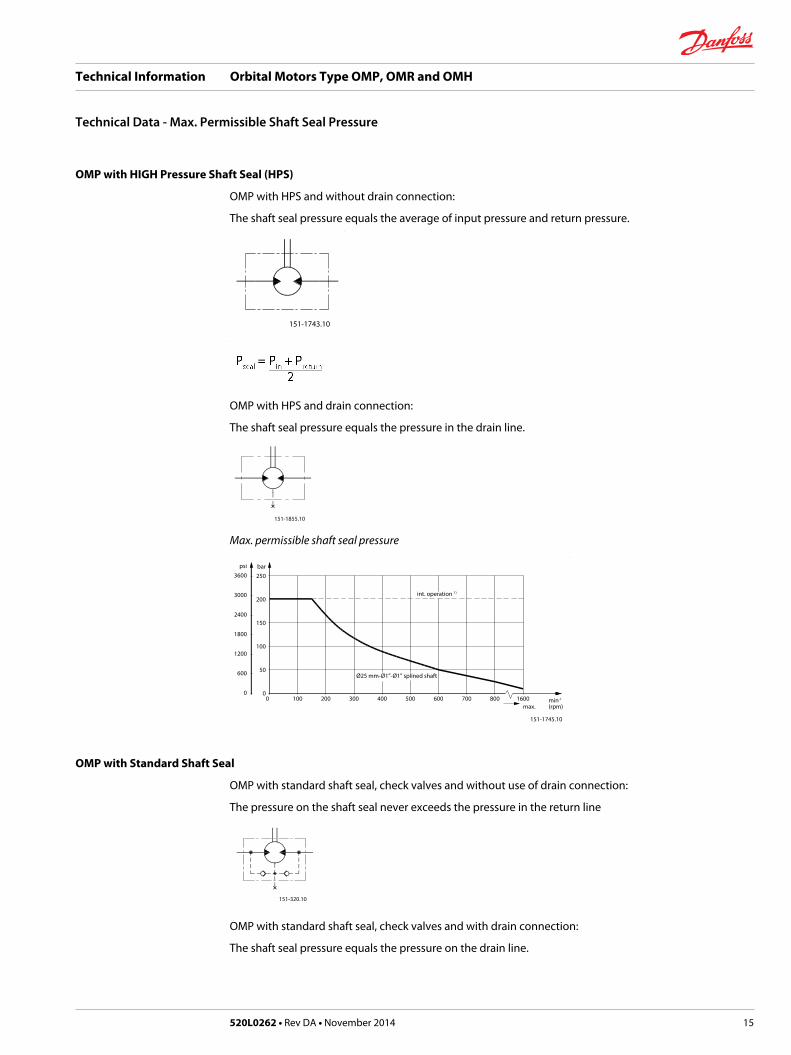
OMP with HIGH Pressure Shaft Seal (HPS)
OMP with HPS and without drain connection:
The shaft seal pressure equals the average of input pressure and return pressure.
151-1743.10
OMP with HPS and drain connection:
The shaft seal pressure equals the pressure in the drain line.
151-1855.10
Max. permissible shaft seal pressure
psi3600
3000
2400
1800
1200
600
0
bar250
200
150
100
50
00 100 200 300 400 500 600 700 800 1600
151-1745.10
int. operation 1)
Ø25 mm-Ø1”-Ø1” splined shaft
max.min-1
(rpm)
OMP with Standard Shaft Seal
OMP with standard shaft seal, check valves and without use of drain connection:
The pressure on the shaft seal never exceeds the pressure in the return line
151-320.10
OMP with standard shaft seal, check valves and with drain connection:
The shaft seal pressure equals the pressure on the drain line.
Technical Information Orbital Motors Type OMP, OMR and OMH
Technical Data - Max. Permissible Shaft Seal Pressure
520L0262 • Rev DA • November 2014 15
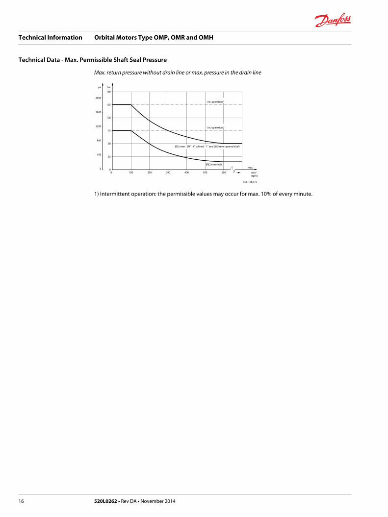
Max. return pressure without drain line or max. pressure in the drain line
psi
2000
1600
1200
800
400
0
bar
150
125
100
75
50
25
00 100 200 300 400 500 600
151-1563.10
int. operation1)
int. operation1)
min-1
(rpm)
Ø25 mm - Ø1” -1” splined - 1” and 28.5 mm tapered shaft
Ø32 mm shaftmax.
1) Intermittent operation: the permissible values may occur for max. 10% of every minute.
Technical Information Orbital Motors Type OMP, OMR and OMH
Technical Data - Max. Permissible Shaft Seal Pressure
16 520L0262 • Rev DA • November 2014

Pressure Drop in Motor
The curve applies to an unloaded motor shaft and an oil viscosity of 35 mm2/s [165 SUS]
psi
400
350
300
250
200
150
100
50
0
bar30
25
20
15
10
5
0
0 10 20 30 40 50 60 70 80 l/min
0 2 4 6 8 10 12 14 16 18 20 US gal/min
151-1744.10
Q
Q
pp
B
A
A: OMP 50 - 400
B: OMP 25 - 40 / OMPW
Oil flow in drain line
The table shows the max. oil flow in the drain line at a return pressure less than 5-10 bar [75-150 psi].
Pressure dropbar [psi]
Viscositymm²/s [SUS]
Oil flow in drain linel/min [US gal/min]
100[1450]
20 [100] 2.5 [0.66]
35 [165] 1.8 [0.78]
140[2030]
20 [100] 3.5 [0.93]
35 [165] 2.8 [0.74]
Direction of Shaft Rotation
151-1836.10
The permissible radial shaft load (PR) depends on• Speed (n)
• Distance (L) from the point of load to the mounting flange
• Mounting flange version
• Shaft version
Mounting flange 4-oval flange**2-hole oval flange(European version)
4-hole oval flange Square flange**2-hole oval flange(US-version)
Technical Information Orbital Motors Type OMP, OMR and OMH
Technical Data
520L0262 • Rev DA • November 2014 17

Shaft version 25 mm cylindrical shaft1 in cylindrical shaft1 in splined shaft
32 mm cylindrical shaft 25 mm cylindrical shaft
Permissible shaft load (PR) - l in mm 800 250000 N*n 95 + L
800 187500 N*n 95 + L
800 250000 N*n 101 + L
Permissible shaft load (PR) - l in inch 800 2215 lbf*n 3.74 + L
800 1660 lbf*n 3.74 + L
800 2215 lbf*n 3.98 + L
* n≥ 200 min-1 [rpm]; ≤ 55 mm [2.2 in]n< 200 min-1 [rpm]; = > PRmax = 8000 N [1800 lbf]** For both European and US-version
151-1203.10
30 [1.18]
24 [0.94]
24 [0.94]
330 lbf1500 N
2000 N440 lbf
A-2 (European-version)
A-2 (US-version)
A-4
PR
PR
PR
C
lbf
2000
1600
1200
800
400
0
N9000
8000
6000
4000
2000
00 200 400 600 800 min-1
(rpm)
--------- cylindrical shaft 32 mm [1.26 in]
______ other shaft versions
The curve shows the relation between PR and n• when l = 30 mm [1.18 in] for motors with A2 (European version) and A4 oval mounting flange
• when l = 24 mm [0.94 in] for motors with square mounting flange and A2 (US version)
For applications with special performance requirements we recommend OMP with the output shaftrunning in needle bearings.
Permissible Shaft Load for OMP N
4400
4000
3600
3200
2800
2400
2000
1600
1200
800
400
0
20000
18000
16000
14000
12000
10000
8000
6000
4000
2000
0
151-2112.10
120 110 100 90 80 70 60 50 40 30 20 10 0 -10 -20 -30 mm
4 3 2 1 0 -1 in
lbf NPrad. Prad.
Pmax.
Pmax.
=
=
2000 N450 lbf
1500 N335 lbf
0 -
50 min-1
200 min-1
800 min-1
A
+
The output shaft on OMP N can be offered in needle bearings. These bearings and the recessed mountingflange allow a higher permissible radial load in comparison to OMP motors.
Technical Information Orbital Motors Type OMP, OMR and OMH
Technical Data
18 520L0262 • Rev DA • November 2014

The permissible radial load on the shaft is shown for different speeds as a function of the distance fromthe mounting flange to the point of load application.
Curve A indicates the max. radial shaft load. Any shaft load exceeding the values quoted in curve A willinvolve risk of breakage.
The other curves apply to a B10 bearing life of 2000 hours at the number of revolutions indicated by thecurve letter. Mineral based hydraulic oil with a sufficient content of anti-wear additives must be used.
Bearing life calculations can be made using the explanation and formula provided in the chapter "Bearingdimensioning" in the technical information "General Orbital Motors" 520L0232 Rev. B.
Permissible Shaft Load for OMPW with Slide Bearings
4400
4000
3600
3200
2800
2400
2000
1600
1200
800
400
0
20000
18000
16000
14000
12000
10000
8000
6000
4000
2000
0
151-2105.10
120 110 100 90 80 70 60 50 40 30 20 10 0 -10 -20 -30 mm
4 3 2 1 0 -1 in
lbf NPrad. Prad.
Pmax.
Pmax.
=
=
2000 N450 lbf
1500 N335 lbf
0 -
400 min-1
200 min-1
800 min-1
A
A
+
The output shaft on OMPW can be offered in slide bearings similar to the other OMP-motors. Thepermissible higher radial load is therefore due to the recessed mounting flange moving the point of loadcloser to the motor bearings.
The permissible radial load on the shaft is shown for different speeds as a function of the distance fromthe mounting flange to the point of load application.
The curves are not based on calculations of B10 bearing life. They represent absolute limits that must notbe exceeded.
Curve A indicates the max. radial shaft load. Any shaft load exceeding the values quoted in curve A willinvolve risk of breakage.
Permissible Shaft Load for OMPW N with Needle Bearing
4400
4000
3600
3200
2800
2400
2000
1600
1200
800
400
0
20000
18000
16000
14000
12000
10000
8000
6000
4000
2000
0
151-2106.10
120 110 100 90 80 70 60 50 40 30 20 10 0 -10 -20 -30 mm
4 3 2 1 0 -1 in
lbf NPrad. Prad.
Pmax.
Pmax.
=
=
2000 N450 lbf
1500 N335 lbf
0-+
50 min-1
200 min-1
800 min-1
A
The output shaft on OMPW N can be offered in needle bearings. These bearings and the recessedmounting flange allow a higher permissible radial load in comparison to OMP motors.
Technical Information Orbital Motors Type OMP, OMR and OMH
Technical Data
520L0262 • Rev DA • November 2014 19
The permissible radial load on the shaft is shown for different speeds as a function of the distance fromthe mounting flange to the point of load application.
Curve A indicates the max. radial shaft load. Any shaft load exceeding the values quoted in curve A willinvolve risk of breakage.
The other curves apply to a B10 bearing life of 2000 hours at the number of revolutions indicated by thecurve letter. Mineral based hydraulic oil with a sufficient content of anti-wear additives must be used.
Bearing life calculations can be made using the explanation and formula provided in the chapter "Bearingdimensioning" in the technical information "General Orbital Motors" 520L0232 Rev. B.
Technical Information Orbital Motors Type OMP, OMR and OMH
Technical Data
20 520L0262 • Rev DA • November 2014

Function Diagrams
Explanation of function diagram use, basis and conditions can be found in Speed, Torque and Output onpage 8.• Continuous range
• Intermittent range (max. 10% operation every minute)
Max. permissible continuous/intermittent pressure drop for the actual shaft version can be found in Technical data for OMP with 25 mm and 1 in cylindrical shaft on page 11.
Intermittent pressure drop and oil flow must not occur simultaneously.
OMP 25lbf• in Nm
450
400
350
300
250
200
150
100
50
0
50
40
30
20
10
0
0 200 400 600 800 1000 1200 1400 1600 1800
151-1369.10
min-1
(rpm)
Q=5
l/m
in[1
.3 U
S ga
l/min
]
10 l/
min
[2.6
US
gal/m
in]
20 l/
min
[5.3
US
gal/m
in]
15 l/
min
[4.0
US
gal/m
in]
40 l/
min
[10.
6 U
S ga
l/min
]
25 l/
min
[6.6
US
gal/m
in]
30 l/
min
[7.9
US
gal/m
in]
35 l/
min
[9.2
US
gal/m
in]
Q=4
5 l/m
in[1
1.9
US
gal/m
in]
∆ p=140 bar
∆ p= 30 bar
1450 psi
2030 psi
1740 psi
80 bar
440 psi
870 psi
1160 psi
60 bar
100 bar
120 bar
N=0.25kW
4kW
N=6kW
1kW
0.5kW
65%1hp
N=6hp
η t =73%
η t =50%
N=0.5hp
4hp
2kW
2hp
OMP 32lbf• in Nm
650
600
550
500
450
400
350
300
250
200
150
100
50
0
70
60
50
40
30
20
10
0
151-1383.10
min-1
(rpm)
Q=5
l/m
in[1
.3 U
S ga
l/min
]
10 l/
min
[2.6
US
gal/m
in]
20 l/
min
[5.3
US
gal/m
in]
30 l/
min
[7.9
US
gal/m
in]
40 l/
min
[10.
6 U
S ga
l/min
]
50 l/
min
[13.
2 U
S ga
l/min
]
15 l/
min
[4.0
US
gal/m
in]
25 l/
min
[6.6
US
gal/m
in]
35 l/
min
[9.2
US
gal/m
in]
45 l/
min
[11.
9US
gal/m
in]
Q=5
5 l/m
in[1
4.5
US
gal/m
in]
∆ p=140 bar
∆ p= 30 bar
1450 psi
1740 psi
2030 psi
80 bar
440 psi
870 psi
1160 psi
60 bar
100 bar
120 bar
N=0.5kW
4kW
N=6kW
73%65%
N=6hp
η t =78%
η t =50%
N=0.5hp
1kW
1hp
4hp2kW
2hp
0 200 400 600 800 1000 1200 1400 1600 1800
OMP 40lbf• in Nm
700
650
600
550
500
450
400
350
300
250
200
150
100
50
0
80
70
60
50
40
30
20
10
0
0 200 400 600 800 1000 1200 1400 1600 1800
151-1384.10
min-1
(rpm)
Q=5
l/m
in[1
.3 U
S ga
l/min
]
10 l/
min
[2.6
US
gal/m
in]
20 l/
min
[5.3
US
gal/m
in]
30 l/
min
[7.9
US
gal/m
in]
40 l/
min
[10.
6 U
S ga
l/min
]
50 l/
min
[13.
2 U
S ga
l/min
]
60 l/
min
[15.
9 U
S ga
l/min
]
Q=7
0 l/m
in[1
8.5U
S ga
l/min
]
∆ p=140 bar
∆ p= 30 bar
1450 psi
1740 psi
2030 psi
80 bar
440 psi
870 psi
1160 psi
60 bar
100 bar
120 bar
N=0.5kW
4kW
N=10kW
1kW
8kW
6kW
75% 70%60%
6hp 8hp
1hp
N=10hp
η t
=78%
η t =50%
N=0.5hp
4hp
2kW2hp
Technical Information Orbital Motors Type OMP, OMR and OMH
Function Diagrams
520L0262 • Rev DA • November 2014 21

OMP 50lbf• in Nm
1100
1000
900
800
700
600
500
400
300
200
100
0
120
110
100
90
80
70
60
50
40
30
20
10
0
151-177.10
min-1
(rpm)
Q=5
l/m
in[1
.3 U
S ga
l/min
]10
l/m
in[2
.6 U
S ga
l/min
]
20 l/
min
[5.3
US
gal/m
in]
30 l/
min
[7.9
US
gal/m
in]
40 l/
min
[10.
6 U
S ga
l/min
]
50 l/
min
[13.
2 U
S ga
l/min
]
60 l/
min
[15.
9 U
S ga
l/min
]
70 l/
min
[18.
5US
gal/m
in]
Q=7
5 l/m
in[1
9.8
US
gal/m
in]
∆ p=175 bar
∆ p= 30 bar
160 bar
1450 psi
2030 psi
1740 psi
2320 psi
2540 psi
80 bar
440 psi
870 psi
1160 psi
60 bar
100 bar
120 bar
140 bar
N=1kW
4kW
10kW N=12kW8kW
6kW
70%
6hp
8hp 10hp N=12hp
η t =75%
η t =50%
60%
N=1hp
4hp
2kW
2hp
0 200 400 600 800 1000 1200 1400 1600
OMP 60 under preparation
OMP 80lbf• in Nm
1800
1600
1400
1200
1000
800
600
400
200
0
200
180
160
140
120
100
80
60
40
20
0
0 100 200 300 400 500 600 700 800 900 1000
151-178.10
min-1
(rpm)
Q=5
l/m
in[1
.3 U
S ga
l/min
]10
l/m
in[2
.6 U
S ga
l/min
]
20 l/
min
[5.3
US
gal/m
in]
30 l/
min
[7.9
US
gal/m
in]
40 l/
min
[10.
6 U
S ga
l/min
]
50 l/
min
[13.
2 U
S ga
l/min
]
60 l/
min
[15.
9 U
S ga
l/min
]
70 l/
min
[18.
5US
gal/m
in]
Q=7
5 l/m
in[1
9.8
US
gal/m
in]
∆ p=175 bar
∆ p= 30 bar
160 bar
1450 psi
2030 psi
1740 psi
2320 psi
2540 psi
80 bar
440 psi
870 psi
1160 psi60 bar
100 bar
120 bar
140 bar
N=1kW
4kW
10kW
N=12kW
8kW
6kW
70%
6hp 8hp
10hp N=12hp
η t =75%
η t =50%
60%N=1hp
4hp
2kW
2hp
OMP 100lbf• in Nm
2200
2000
1800
1600
1400
1200
1000
800
600
400
200
0
240
220
200
180
160
140
120
100
80
60
40
20
0
0 100 200 300 400 500 600 700 800
151-179.10
min-1
(rpm)
Q=5
l/m
in[1
.3 U
S ga
l/min
]10
l/m
in[2
.6 U
S ga
l/min
]
20 l/
min
[5.3
US
gal/m
in]
30 l/
min
[7.9
US
gal/m
in]
40 l/
min
[10.
6 U
S ga
l/min
]
50 l/
min
[13.
2 U
S ga
l/min
]
60 l/
min
[15.
9 U
S ga
l/min
]
70 l/
min
[18.
5US
gal/m
in]
Q=7
5 l/m
in[1
9.8
US
gal/m
in]
∆ p=175 bar
∆ p= 30 bar
160 bar
1450 psi
2030 psi
1740 psi
2320 psi
2540 psi
80 bar
440 psi
870 psi
1160 psi60 bar
100 bar
120 bar
140 bar
N=1kW
4kW
10kW N=12kW
8kW
6kW
75%
70%
6hp 8hp 10hp
N=12hp
η t =78%
η t =50%60%
N=1hp
4hp
2kW
2hp
Technical Information Orbital Motors Type OMP, OMR and OMH
Function Diagrams
22 520L0262 • Rev DA • November 2014

OMP 110 under preparation
OMP 125lbf• in Nm
3000
2500
2000
1500
1000
500
0
320
280
240
200
160
120
80
40
0
0 50 100 150 200 250 300 350 400 450 500 550 600
151-1416.10
min-1
(rpm)
Q=5
l/m
in[1
.3 U
S ga
l/min
]10
l/m
in[2
.6 U
S ga
l/min
]
20 l/
min
[5.3
US
gal/m
in]
30 l/
min
[7.9
US
gal/m
in]
40 l/
min
[10.
6 U
S ga
l/min
]
50 l/
min
[13.
2 U
S ga
l/min
]
60 l/
min
[15.
9 U
S ga
l/min
]
70 l/
min
[18.
5US
gal/m
in]
Q=7
5 l/m
in[1
9.8
US
gal/m
in]
160 bar
∆ p= 30 bar
1160 psi
2030 psi
2320 psi
∆ p=175 bar2540 psi
440 psi
870 psi60 bar
80 bar
140 bar
1740 psi120 bar
1450 psi100 bar
N=1kW
4kW
6kW
N=10kW
8kW
75%
70%
8hp
6hp
N=10hp
η t =78%
η t =50%60%
N=1hp
4hp2kW2hp
OMP 160lbf• in Nm
3600
3200
2800
2400
2000
1600
1200
800
400
0
400
360
320
280
240
200
160
120
80
40
0
0 50 100 150 200 250 300 350 400 450 500
151-180.10
min-1
(rpm)
Q=5
l/m
in[1
.3 U
S ga
l/min
]10
l/m
in[2
.6 U
S ga
l/min
]
20 l/
min
[5.3
US
gal/m
in]
30 l/
min
[7.9
US
gal/m
in]
40 l/
min
[10.
6 U
S ga
l/min
]
50 l/
min
[13.
2 U
S ga
l/min
]
60 l/
min
[15.
9 U
S ga
l/min
]
70 l/
min
[18.
5US
gal/m
in]
Q=7
5 l/m
in[1
9.8
US
gal/m
in]
∆ p=175 bar
∆ p= 30 bar
160 bar
1450 psi
2030 psi
1740 psi
2320 psi
2540 psi
80 bar
440 psi
870 psi
1160 psi60 bar
100 bar
120 bar
140 bar
N=1kW
4kW
10kW N=12kW8kW6kW
75%
70%
6hp 8hp
10hp
N=12hp
η t =78%
η t =50%60%
N=1hp
4hp2kW
2hp
OMP 200lbf• in Nm
4500
4000
3500
3000
2500
2000
1500
1000
500
0
500
450
400
350
300
250
200
150
100
50
0
0 50 100 150 200 250 300 350 400
151-181.10
min-1
(rpm)
Q=5
l/m
in[1
.3 U
S ga
l/min
]10
l/m
in[2
.6 U
S ga
l/min
]
20 l/
min
[5.3
US
gal/m
in]
30 l/
min
[7.9
US
gal/m
in]
40 l/
min
[10.
6 U
S ga
l/min
]
50 l/
min
[13.
2 U
S ga
l/min
]
60 l/
min
[15.
9 U
S ga
l/min
]
70 l/
min
[18.
5US
gal/m
in]
Q=7
5 l/m
in[1
9.8
US
gal/m
in]
∆ p=175 bar
∆ p= 30 bar
150 bar
1450 psi
2030 psi
1670 psi
2180 psi
2540 psi
80 bar
440 psi
870 psi
1160 psi60 bar
100 bar
115 bar
140 bar
N=1kW
4kW
N=10kW
8kW
6kW
75%
70%
6hp
8hp
10hp
η t =77%
η t =50%60%
N=1hp
4hp2kW
2hp
Technical Information Orbital Motors Type OMP, OMR and OMH
Function Diagrams
520L0262 • Rev DA • November 2014 23

OMP 250lbf• in Nm
5500
5000
4500
4000
3500
3000
2500
2000
1500
1000
500
0
600
550
500
450
400
350
300
250
200
150
100
50
0
151-1244.10
min-1
(rpm)
Q=5
l/m
in[1
.3 U
S ga
l/min
]10
l/m
in[2
.6 U
S ga
l/min
]
20 l/
min
[5.3
US
gal/m
in]
30 l/
min
[7.9
US
gal/m
in]
40 l/
min
[10.
6 U
S ga
l/min
]
50 l/
min
[13.
2 U
S ga
l/min
]
60 l/
min
[15.
9 U
S ga
l/min
]
70 l/
min
[18.
5US
gal/m
in]
Q=7
5 l/m
in[1
9.8
US
gal/m
in]
∆ p=175 bar
∆ p= 30 bar
160 bar
1450 psi
2030 psi
1810 psi
2320 psi
2540 psi
85 bar
440 psi
870 psi
1230 psi
60 bar
100 bar
125 bar
140 bar
N=1kW
4kW
N=10kW8kW
6kW
75%70%60%
6hp
8hpN=10hp
η t =80%
η t =50%
N=1hp
4hp
2kW2hp
0 25 50 75 100 125 150 175 200 225 250 275 300 325
OMP 315lbf• in Nm
6000
5500
5000
4500
4000
3500
3000
2500
2000
1500
1000
500
0
640
560
480
400
320
240
160
80
0
0 25 50 75 100 125 150 175 200 225 250
151-182.10
min-1
(rpm)
Q=5
l/m
in[1
.3 U
S ga
l/min
]10
l/m
in[2
.6 U
S ga
l/min
]
20 l/
min
[5.3
US
gal/m
in]
30 l/
min
[7.9
US
gal/m
in]
40 l/
min
[10.
6 U
S ga
l/min
]
50 l/
min
[13.
2 U
S ga
l/min
]
60 l/
min
[15.
9 U
S ga
l/min
]
70 l/
min
[18.
5US
gal/m
in]
Q=7
5 l/m
in[1
9.8
US
gal/m
in]
∆ p=160 bar
∆ p= 30 bar
1450 psi
2030 psi
1740 psi
2320 psi
85 bar
440 psi
1020 psi
1230 psi70 bar
730 psi50 bar
100 bar
120 bar
140 bar
N=1kW
4kW
N=8kW
6kW
70%
6hp
8hp N=10hp
η t =73%
η t =50%60%
N=1hp
4hp2kW2hp
OMP 400lbf• in Nm
6000
5500
5000
4500
4000
3500
3000
2500
2000
1500
1000
500
0
650
600
550
500
450
400
350
300
250
200
150
100
50
0
151-1161.10
min-1
(rpm)
Q=5
l/m
in[1
.3 U
S ga
l/min
]
10 l/
min
[2.6
US
gal/m
in]
20 l/
min
[5.3
US
gal/m
in]
30 l/
min
[7.9
US
gal/m
in]
40 l/
min
[10.
6 U
S ga
l/min
]
50 l/
min
[13.
2 U
S ga
l/min
]
60 l/
min
[15.
9 U
S ga
l/min
]
70 l/
min
[18.
5US
gal/m
in]
Q=7
5 l/m
in[1
9.8
US
gal/m
in]
∆ p=125 bar
∆ p= 30 bar
110 bar
940 psi
1380 psi
1160 psi
1600 psi
1810 psi
55 bar
440 psi
650 psi
800 psi45 bar
65 bar
80 bar
95 bar
N=1kW
4kW
N=6kW
75%
60%70%
6hp
N=8hp
η t =80%
η t =50%
N=1hp
4hp2kW2hp
0 25 50 75 100 125 150 175 200
Technical Information Orbital Motors Type OMP, OMR and OMH
Function Diagrams
24 520L0262 • Rev DA • November 2014

Shaft Version
8.000 [0.315]7.964 [0.314]
43.8 [1.724]42.5 [1.673]
max. 6 [0.24]min. 18 [0.71]
R0.5[0.020]
45˚
32.0 [1.260]31.7 [1.248]
6.40 [0.252]4.40 [0.173]
M8
Ø28
.56
[1.1
24]
28.0
[1.1
02]
27.7
[1.0
90]
Ø25
.015
[0.9
85]
Ø25
.002
[0.9
84]
D
A-A
6.40 [0.252]6.35 [0.250]
28.1
9 [1
.110
]27
.93
[1.1
00]
E
A-A
6.40 [0.252]6.35 [0.250]
151-1842.12
28.1
9 [1
.110
]27
.93
[1.1
00]
F
A-A
A
A
A
43.8 [1.724]42.5 [1.673]
max. 6 [0.24]
min. 18 [0.71]
R0.5[0.020]
45˚
31.75 [1.250]31.45 [1.238]
31.75 [1.250]31.45 [1.238]
5.5 [0.217]3.5 [0.138]
5.5 [0.217]3.5 [0.138]
M8
Ø28
.56
[1.1
24]
Ø25
.40
[1.0
00]
Ø25
.38
[0.9
99]
Ø25
.40
[1.0
00]
Ø25
.38
[0.9
99]
B
A
A
38.8 [1.528]36.8 [1.448]
max. 6 [0.24]
¼ -20 UNC
min. 18 [0.71]
R0.5[0.020]
45˚
14 [0.55]
Ø28
.56
[1.1
24]
C
A
A
A: Cylindrical shaft25 mm
B: Cylindrical shaft1 in
US versionC: Cylindrical shaft1 in
D: Parallel keyA8 • 7 • 32DIN 6885
E: Parallel key1/4 • 1/4 • 11/4 inB.S. 46
F: Parallel key1/4 • 1/4 • 11/4 inB.S. 46
Technical Information Orbital Motors Type OMP, OMR and OMH
Shaft Version
520L0262 • Rev DA • November 2014 25
151-1843.11
10.00 [0.394]9.964 [0.392]
max. 6 [0.24]min. 18 [0.71]
R0.5[0.020]
45˚
45.0 [1.772]44.7 [1.760]
56.95 [2.242]55.35 [2.179]
5.50 [0.217]4.50 [0.177]
M8
35.0
0 [1
.38]
34.8
0 [1
.37]
Ø32
.018
[1.2
61]
Ø32
.002
[1.2
60]
Ø35
.0 [1
.378
]
I
A-A
*21.540 [0.848]*21.400 [0.843]
6x60˚
6.27
5 [0
.247
]6.
201
[0.2
44]
A-A
5.00 [0.197]4.97 [0.196]
15.2
9 [0
.602
]15
.24
[0.6
00]
J
A-A
D
A
A
max. 6 [0.24]min. 18 [0.71]
R0.5[0.020]
45˚
27.4 [1.079]25.4 [1.000]R max. 42.5 [1.673]
43.8 [1.724]42.5 [1.673]
1.2 [0.039]x45˚0.8 [0.031]x45˚
M8
Ø25
.348
[0.9
98]
Ø25
.348
[0.9
98]
Ø28
.56
[1.1
24]
E
A
24.4 [0.961]23.6 [0.929] 20.5 [0.807]
Ø28
.56
[1.1
24]
Ø4.
5 [0
.177
]
M20
x1.5
[0.0
59]
ø44
[1.7
3]
F
AG H
A
A
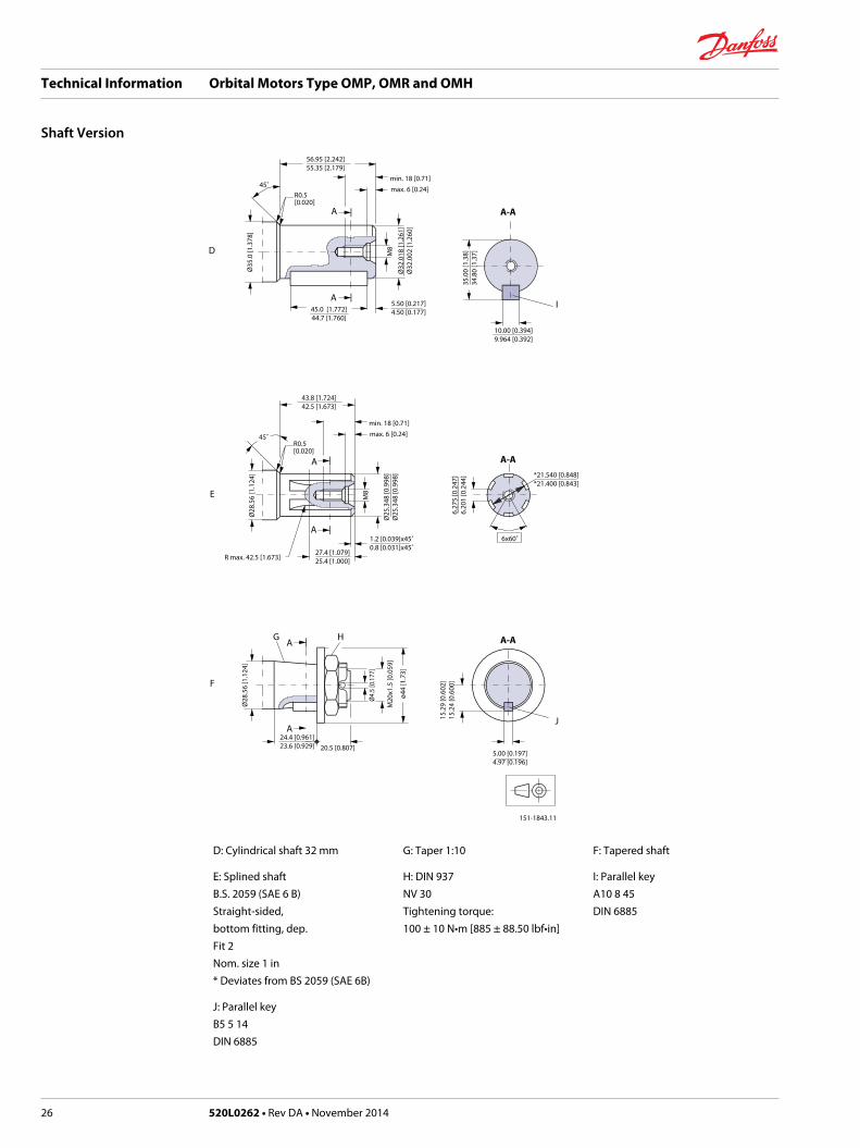
D: Cylindrical shaft 32 mm G: Taper 1:10 F: Tapered shaft
E: Splined shaftB.S. 2059 (SAE 6 B)Straight-sided,bottom fitting, dep.Fit 2Nom. size 1 in* Deviates from BS 2059 (SAE 6B)
H: DIN 937NV 30Tightening torque:100 ± 10 N•m [885 ± 88.50 lbf•in]
I: Parallel keyA10 8 45DIN 6885
J: Parallel keyB5 5 14DIN 6885
Technical Information Orbital Motors Type OMP, OMR and OMH
Shaft Version
26 520L0262 • Rev DA • November 2014
Port Thread Versions
D
G
A
H
B
E
F
J
C
I
max. Ø21.5 [0.846] Ø30.5 [1.200]Ø29.5 [1.161]
2x max 21.5 [0.84]
max
. 27
[1.0
6]
min
. 16.
7 [0
.657
]
1.0
[0.0
4]
min
. 15
[0.5
9]
Ø18.5 [0.728]Ø17.5 [0.689]
min
. 12
[0.4
7]
max
. 0.6
[0.0
24]
12.2
[0.4
73]
11.8
[0.4
65]
151-1844.11
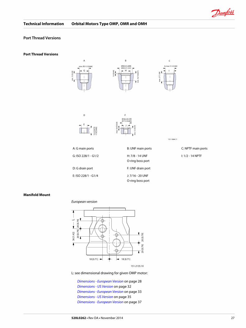
A: G main ports B: UNF main ports C: NPTF main ports
G: ISO 228/1 - G1/2 H: 7/8 - 14 UNFO-ring boss port
I: 1/2 - 14 NPTF
D: G drain port F: UNF drain port
E: ISO 228/1 - G1/4 J: 7/16 - 20 UNFO-ring boss port
Manifold Mount
European version
18 [0.71] 18 [0.71]
151-2135.10
20 [0
.79]
20 [0
.79]
20 [0
.79]
20 [0
.79]
36 [1
.42]
L
L: see dimensional drawing for given OMP motor:
Dimensions - European Version on page 28Dimensions - US Version on page 32Dimensions - European Version on page 33Dimensions - US Version on page 35Dimensions - European Version on page 37
Technical Information Orbital Motors Type OMP, OMR and OMH
Port Thread Versions
520L0262 • Rev DA • November 2014 27

Dimensions
Side port version with 2 hole oval mounting flange (A2-flange).Ø82.55 [3.250]Ø82.45 [3.246]
Ø13.5 [0.53]
18 [0.71]18 [0.71]
max. Ø93 [3.66]
106.4 [4.189]
max. 133 [5.24]
151-1840.11
8 [0
.31]
16 [0
.63]
36 [1
.42]
38 [1
.50]
max
. 55.
3 [2
.177
]
55 [2
.17]m
ax. 1
03 [4
.06]
E
LL 1
D
D: G 1⁄2; 15 mm [0.59 in] deep E: M8; 13 mm [0.51 in] deep(4 pcs.)
Type Max. Lmm [in]
L1mm [in]
OMP 25 130.0 [5.12] 4.1 [0.16]
OMP 32 131.0[5.16] 5.2[0.20]
OMP 40 132.0 [5.20] 6.5 [0.26]
OMP 50 132.0 [5.20] 6.5 [0.26]
OMP 80 136.0 [5.35] 10.4 [0.41]
OMP 100 138.5 [5.45] 13.0 [0.51]
OMP 125 142.0 [5.59] 16.7 [0.66]
OMP 160 146.5 [5.77] 20.8 [0.82]
OMP 200 151.5 [5.96] 26.0 [1.02]
OMP 250 158.0[6.22] 32.5 [1.28]
OMP 315 166.5 [6.56] 40.9 [1.61]
OMP 400 177.6 [6.99] 52.0 [2.05]
Technical Information Orbital Motors Type OMP, OMR and OMH
Dimensions - European Version
28 520L0262 • Rev DA • November 2014

Side port version with 2 hole oval mounting flange (A2-flange). With drain connection.Ø82.55 [3.250]Ø82.45 [3.246]
Ø13.5 [0.53]
18 [0.71]18 [0.71]
max. Ø93 [3.66]
106.4 [4.189]
max. 133 [5.24]
151-1850.11
16 [0
.63]
8 [0
.31]
36 [1
.42]
38 [1
.50]
max
. 6 [0
.24]
max
. 55.
3 [2
.177
]55
[2.1
7]max
. 103
[4.0
6]
E
C
LL 1
D
C: Drain connectionG ¼; 12 mm [0.47 in] deep
D: G ½; 15 mm [0.59 in] deep
E: M8; 13 mm [0.51 in] deep(4 pcs.)
Type Max.Lmm [in]
L1mm [in]
OMP 25 130.0 [5.12] 4.1 [0.16]
OMP 32 131.0 [5.16] 5.2 [0.20]
OMP 40 132.0 [5.20] 6.5 [0.26]
OMP 50 132.0 [5.20] 6.5 [0.26]
OMP 80 136.0 [5.35] 10.4 [0.41]
OMP 100 138.5 [5.45] 13.0 [0.51]
OMP 125 142.0 [5.59] 16.7 [0.66]
OMP 160 146.5 [5.77] 20.8 [0.82]
OMP 200 151.5 [5.96] 26.0 [1.02]
OMP 250 158.0 [6.22] 32.5 [1.28]
OMP 315 166.5 [6.56] 40.9 [1.61]
OMP 400 177.6 [6.99] 52.0 [2.05]
Technical Information Orbital Motors Type OMP, OMR and OMH
Dimensions - European Version
520L0262 • Rev DA • November 2014 29

OMP C and OMP N Side port version with 2 hole oval mounting flange (A2-flange).Ø82.55 [3.250]Ø82.45 [3.246]
Ø13.5 [0.53]
18 [0.71]18 [0.71]
max. Ø93 [3.66]
106.4 [4.189]
max. 133 [5.24]
151-1841.12
16 [0
.63]
8 [0
.31]
36 [1
.42]
38 [1
.50]
m
ax. 5
5.3
[2.1
77]
max
. 6 [0
.24]
55 [2
.17]m
ax. 1
03 [4
.06]
E
C
LL 1
D
C: Drain connectionG ¼; 12 mm [0.47 in] deep
D: G ½; 15 mm [0.59 in] deep
E: M8; 13 mm [0.51 in] deep(4 pcs.)
Type Max. Lmm [in]
L1mm [in]
OMP 50 132.0 [5.20] 6.5 [0.26]
OMP 80 136.0 [5.35] 10.4 [0.41]
OMP 100 138.5 [5.45] 13.0 [0.51]
OMP 125 142.0[5.59] 16.7 [0.66]
OMP 160 146.5 [5.77] 20.8[0.82]
OMP 200 151.5 [5.97] 26.0 [1.02]
OMP 250 158.0 [6.22] 32.5 [1.28]
OMP 315 166.5 [6.56] 40.9 [1.61]
OMP 400 177.6 [6.99] 52.0 [2.05]
Technical Information Orbital Motors Type OMP, OMR and OMH
Dimensions - European Version
30 520L0262 • Rev DA • November 2014

End port version with 2 hole oval mounting flange (A2-flange).
Ø82.55 [3.250]Ø82.45 [3.246]
Ø13.5 [0.53]
max. 100.5 [3.967]
62.4 [2.457]
max. Ø93 [3.66]
106.4 [4.189]
max. 133 [5.24]
151-1748.11
16 [0
.63]
8 [0
.31]
7.1
[0.2
80]
5 [0
.20]
max
. 55.
3 [2
.177
]
55 [2
.17]
max
. 9.1
[0.3
58]
max
. 108
[4.2
5]
C
LL 1
D
C: Drain connectionG ¼; 12 mm [0.47 in] deep
D: G ½; 15 mm [0.59 in] deep
Type Max. Lmm [in]
L1mm [in]
OMP 50 146.1 [5.75] 6.5 [0.26]
OMP 80 150.0 [5.91] 10.4 [0.41]
OMP 100 152.7 [6.01] 13.0 [0.51]
OMP 125 156.2 [6.15] 16.7 [0.66]
OMP 160 160.4 [6.32] 20.8 [0.82]
OMP 200 165.6 [6.52] 26.0 [1.02]
OMP 250 172.1 [6.78] 32.5 [1.28]
OMP 315 180.5 [7.11] 40.9 [1.61]
OMP 400 191.6 [7.54] 52.0 [2.05]
Technical Information Orbital Motors Type OMP, OMR and OMH
Dimensions - European Version
520L0262 • Rev DA • November 2014 31
Dimensions
Side port version with 2 hole oval mounting flange (A2-flange).Ø82.55 [3.250]Ø82.45 [3.246]
Ø13.5 [0.53]
18 [0.71]18 [0.71]
max. Ø93 [3.66]
106.4 [4.189]
max. 133 [5.24]
151-1217.11
22 [0
.87]
2.6
[0.1
02]
44 [1
.73]
36 [1
.42]
max
. 45.
9 [1
.81]
max
. 6 [0
.24]
55 [2
.17]
max
. 103
[4.0
6]
E
C
L
L 1
D
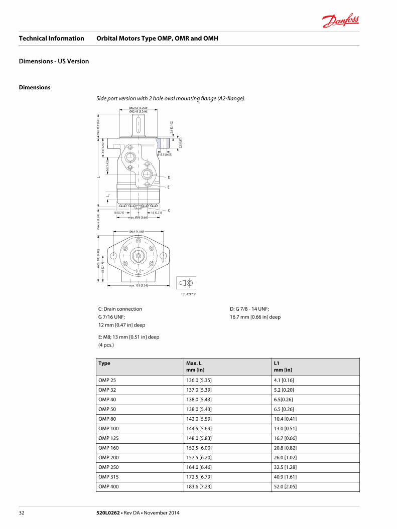
C: Drain connectionG 7/16 UNF;12 mm [0.47 in] deep
D: G 7/8 - 14 UNF;16.7 mm [0.66 in] deep
E: M8; 13 mm [0.51 in] deep(4 pcs.)
Type Max. Lmm [in]
L1mm [in]
OMP 25 136.0 [5.35] 4.1 [0.16]
OMP 32 137.0 [5.39] 5.2 [0.20]
OMP 40 138.0 [5.43] 6.5[0.26]
OMP 50 138.0 [5.43] 6.5 [0.26]
OMP 80 142.0 [5.59] 10.4 [0.41]
OMP 100 144.5 [5.69] 13.0 [0.51]
OMP 125 148.0 [5.83] 16.7 [0.66]
OMP 160 152.5 [6.00] 20.8 [0.82]
OMP 200 157.5 [6.20] 26.0 [1.02]
OMP 250 164.0 [6.46] 32.5 [1.28]
OMP 315 172.5 [6.79] 40.9 [1.61]
OMP 400 183.6 [7.23] 52.0 [2.05]
Technical Information Orbital Motors Type OMP, OMR and OMH
Dimensions - US Version
32 520L0262 • Rev DA • November 2014

Dimensions
Side port version with 4 hole oval mounting flange (A4-flange).Ø82.55 [3.250]Ø82.45 [3.246]
Ø13.5 [0.53]
18 [0.71]18 [0.71]
max. Ø93 [3.66]
106.4 [4.189]
max. 133 [5.24]
151-1747.12
16 [0
.63]
8 [0
.31]
36 [1
.42]
38 [1
.50]
max
. 68.
3 [2
.689
]m
ax. 6
[0.2
4]
55 [2
.17]
45˚
max
. 103
[4.0
6]
E
C
LL 1
D
C: Drain connectionG ¼; 12 mm [0.47 in] deep
D: G ½; 15 mm [0.59 in] deep
E: M8; 13 mm [0.51 in] deep(4 pcs.)
Type Max. Lmm [in]
L1mm [in]
OMP 50 132.0 [5.20] 6.5 [0.26]
OMP 80 136.0 [5.35] 10.4 [0.41]
OMP 100 138.5 [5.45] 13.0 [0.51]
OMP 125 142.0 [5.59] 16.7 [0.66]
OMP 160 146.5 [5.77] 20.8 [0.82]
OMP 200 151.5 [5.97] 26.0 [1.02]
OMP 250 158.0 [6.22] 32.5 [1.28]
OMP 315 166.5 [6.56] 40.9 [1.61]
OMP 400 177.6 [6.99] 52.0 [2.05]
Technical Information Orbital Motors Type OMP, OMR and OMH
Dimensions - European Version
520L0262 • Rev DA • November 2014 33
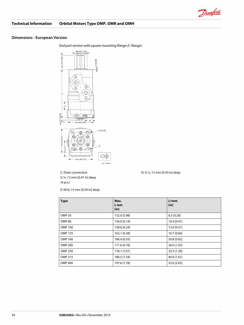
End port version with square mounting flange (C-flange).Ø44.45 [1.750]Ø44.35 [1.746]
R15 [0.59]
max. Ø93 [3.66]
max. 84 [3.31]
151-1749.11
2.5
[0.0
98]
max
. 45.
9 [1
.949
]m
ax. 9
.1 [0
.358
]
55 [2
.17]
max
. 84
[3.3
1]
E
C
LL 1
D
C: Drain connectionG ¼; 12 mm [0.47 in] deep(4 pcs.)
D: G ½; 15 mm [0.59 in] deep
E: M10; 15 mm [0.59 in] deep
Type Max.L mm[in]
L1mm[in]
OMP 50 152.0 [5.98] 6.5 [0.26]
OMP 80 156.0 [6.14] 10.4 [0.41]
OMP 100 158.6 [6.24] 13.0 [0.51]
OMP 125 162.1 [6.38] 16.7 [0.66]
OMP 160 166.4 [6.55] 20.8 [0.82]
OMP 200 171.6 [6.76] 26.0 [1.02]
OMP 250 178.1 [7.01] 32.5 [1.28]
OMP 315 186.5 [7.34] 40.9 [1.61]
OMP 400 197.6 [7.78] 52.0 [2.05]
Technical Information Orbital Motors Type OMP, OMR and OMH
Dimensions - European Version
34 520L0262 • Rev DA • November 2014

Dimensions
Side port version with square mounting flange (C-flange).
Ø44.45 [1.750]Ø44.35 [1.746]
Ø82.55
[3.25
0]
18 [0.71] 18 [0.71]
max. Ø93 [3.66]
R15 [0.59]
max. 84 [3.31]
151-1214.11
max
. 84
[3.3
1]
2.5
[0.2
98]
44 [1
.73]
36 [1
.42]
max
. 46.
3 [1
.823
]6
[0.2
4]
55 [2
.17]
max
. 103
[4.0
6]
E
C
LL 1
F
D
C: Drain connection7/16 - 20 UNF;12 mm [0.47 in] deep
D: 7/8 - 14 UNF;16.76 mm [0.66 in] deepor 1/2 - 14 NPTF
E: 3/8 - 16 UNC;15 mm [0.59 in] deep(4 off)
F: M8; 13 mm [0.51 in] deep(4 pcs.)
Type Max. Lmm [in]
L1mm [in]
OMP 50 132.0 [5.20] 6.5 [0.26]
OMP 80 136.0[5.35] 10.4[0.41]
OMP 100 138.5 [5.45] 13.0 [0.51]
OMP 125 142.0[5.59] 16.7 [0.66]
Technical Information Orbital Motors Type OMP, OMR and OMH
Dimensions - US Version
520L0262 • Rev DA • November 2014 35

Type Max. Lmm [in]
L1mm [in]
OMP 160 146.5 [5.77] 20.8 [0.82]
OMP 200 151.5 [5.97] 26.0 [1.02]
OMP 250 158.0 [6.22] 32.5 [1.28]
OMP 315 166.5 [6.56] 40.9 [1.61]
OMP 400 177.6 [6.99] 52.0 [2.05]
Technical Information Orbital Motors Type OMP, OMR and OMH
Dimensions - US Version
36 520L0262 • Rev DA • November 2014

Dimensions
OMPW and OMPW N wheel motorØ79.2 [3.118]Ø78.8 [3.102]
Ø80.000 [3.150]Ø79.954 [3.148]
max 81 [3.19]
18.5 [0.728] 18.5 [0.728]
max
. 102
[4.0
2]
151-1360.11
max
. 69
[2.7
2]40
[1.5
7]
20 [0
.79]
55 [2.17]
max. 107 [4.21]
max. 87 [3.43]
103 [4.06]
max. 127 [5
.00]
7.25
[0.2
85]
max
. 6 [0
.24] C
E
L
L 1
L 2
DR0
.5 [0
.020
] max
.
C: Drain connectionG ¼; 12 mm [0.47 in] deep
D: G ½; 15 mm [0.59 in] deep
E: M10; 20 mm [0.79 in] deep(4 pcs.)
Output shaft.max. L2mm [in]
Cylindrical shaft 25 mm [0.98 in] max. 115 [4.53]
Tapered shaft 28.56 mm [1.12 in] max. 117.8 [4.64]
Type Max. Lmm [in]
L1mm [in]
OMP 50 71.8 [2.83] 6.5 [0.26]
OMP 80. 75.7 [2.98] 10.4 [0.41]
OMP 100 78.3 [3.08] 13.0 [0.51]
OMP 125 81.6 [3.21] 16.7 [0.66]
OMP 160 86.1 [3.39] 20.8 [0.82]
OMP 200 91.3 [3.60] 26.0 [1.02]
Technical Information Orbital Motors Type OMP, OMR and OMH
Dimensions - European Version
520L0262 • Rev DA • November 2014 37

Type Max. Lmm [in]
L1mm [in]
OMP 250 97.8 [3.85] 32.5 [1.28]
OMP 315 106.2 [4.18] 40.9 [1.61]
OMP 400 117.3 [4.62] 52.0 [2.05]
Technical Information Orbital Motors Type OMP, OMR and OMH
Dimensions - European Version
38 520L0262 • Rev DA • November 2014

Versions
Mounting flange Spigotdiameter(front/rearend)
Bolt circlediameter(BC)
Shaft Portsize
EU US Sideport
Endport
Flange port
Std.shaftseal
Highpressureshaftseal
Drainconnection
Checkvalve
Maintypedesignation
2 hole oval flange(A2-flange)
∅ 82.5 mm[3.25 in]
∅ 106.4 mm[4.20 in]
Cyl. 25 mm G ½ * * * No No OMR
G ½ * * * Yes Yes OMR
G ½ * * * Yes Yes OMR
Cyl.1 inch
G ½ * * * No No OMR
G ½ * * * Yes Yes OMR
7/8 - 14UNF
* * * Yes Yes OMR
Splined1 inch
G ½ * * * No No OMR
G ½ * * * Yes Yes OMR
7/8 - 14UNF
* * * Yes Yes OMR
Cyl. 32 mm G ½ * * * Yes Yes OMR
Tap. 28.5mm
G ½ * * * Yes Yes OMR
4 hole oval flange(A4-flange)
∅ 82.5 mm[3.25 in]
∅ 106.4 mm[4.20 in]
Cyl. 25 mm G ½ * * * Yes Yes OMR
Cyl. 32 mm G ½ * * * Yes Yes OMR
Cyl. 1¼ in 7/8 - 14UNF
* * * Yes Yes OMR
Square flange(C-flange)
∅ 44.4 mm[1.75 in]
∅ 82.5 mm[3.25 in]
Cyl. 25 mm G ½ * * * Yes Yes OMR
Cyl. 1 in 7/8 - 14UNF
* * * Yes Yes OMR
OMR motors with corrosion resistant parts
2 hole oval flange(A2-flange)
∅ 82.5 mm[3.25 in]
∅ 106.4 mm[4.20 in]
Cyl. 25 mm G ½ * * * Yes Yes OMR C
OMR motors with needle bearings
2 hole oval flange(A2-flange)
∅ 82.5 mm[3.25 in]
∅ 106.4 mm[4.20 in]
Cyl. 25 mm G ½ * * * Yes Yes OMR N
Wheel ∅ 82.5 mm[3.25 in]
∅ 147.6 mm[5.81 in]
Tap. 35mm
G ½ * * * Yes Yes OMRWN
Tap. 1¼ in 7/8 - 14UNF
* * * Yes Yes OMRWN
OMR motors with integrated brake
2 hole oval flange(A2-flange)
∅ 82.5 mm[3.25 in]
∅ 106.4 mm[4.20 in]
Cyl. 25 mm G ½ * * * Yes Yes OMR F
OMR motors with integrated brake and needle bearings
2 hole oval flange(A2-flange)
∅ 82.5 mm[3.25 in]
∅ 106.4 mm[4.20 in]
Cyl. 1 in 7/8 - 14UNF
* * * Yes Yes OMR NF
Wheel ∅ 82.5 mm[3.25 in]
∅ 147.6 mm[5.81 in]
Tap. 35mm
G ½ * * * Yes Yes OMRWNF
* Version is available.
Technical Information Orbital Motors Type OMP, OMR and OMH
Versions
520L0262 • Rev DA • November 2014 39
Features available (options)
Low leakage (low speed valve) Reverse rotation
Speed sensor Painted
Viton shaft seal
Technical Information Orbital Motors Type OMP, OMR and OMH
Versions
40 520L0262 • Rev DA • November 2014
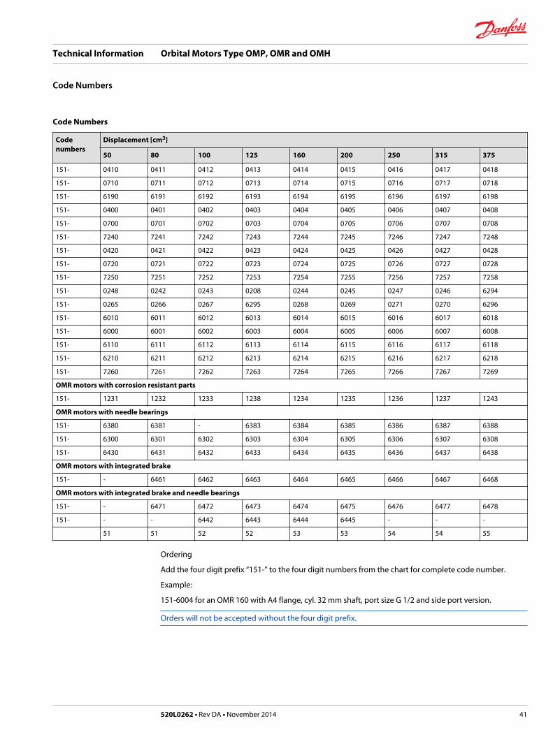
Code Numbers
Codenumbers
Displacement [cm3]
50 80 100 125 160 200 250 315 375
151- 0410 0411 0412 0413 0414 0415 0416 0417 0418
151- 0710 0711 0712 0713 0714 0715 0716 0717 0718
151- 6190 6191 6192 6193 6194 6195 6196 6197 6198
151- 0400 0401 0402 0403 0404 0405 0406 0407 0408
151- 0700 0701 0702 0703 0704 0705 0706 0707 0708
151- 7240 7241 7242 7243 7244 7245 7246 7247 7248
151- 0420 0421 0422 0423 0424 0425 0426 0427 0428
151- 0720 0721 0722 0723 0724 0725 0726 0727 0728
151- 7250 7251 7252 7253 7254 7255 7256 7257 7258
151- 0248 0242 0243 0208 0244 0245 0247 0246 6294
151- 0265 0266 0267 6295 0268 0269 0271 0270 6296
151- 6010 6011 6012 6013 6014 6015 6016 6017 6018
151- 6000 6001 6002 6003 6004 6005 6006 6007 6008
151- 6110 6111 6112 6113 6114 6115 6116 6117 6118
151- 6210 6211 6212 6213 6214 6215 6216 6217 6218
151- 7260 7261 7262 7263 7264 7265 7266 7267 7269
OMR motors with corrosion resistant parts
151- 1231 1232 1233 1238 1234 1235 1236 1237 1243
OMR motors with needle bearings
151- 6380 6381 - 6383 6384 6385 6386 6387 6388
151- 6300 6301 6302 6303 6304 6305 6306 6307 6308
151- 6430 6431 6432 6433 6434 6435 6436 6437 6438
OMR motors with integrated brake
151- - 6461 6462 6463 6464 6465 6466 6467 6468
OMR motors with integrated brake and needle bearings
151- - 6471 6472 6473 6474 6475 6476 6477 6478
151- - - 6442 6443 6444 6445 - - -
51 51 52 52 53 53 54 54 55
Ordering
Add the four digit prefix “151-” to the four digit numbers from the chart for complete code number.
Example:
151-6004 for an OMR 160 with A4 flange, cyl. 32 mm shaft, port size G 1/2 and side port version.
Orders will not be accepted without the four digit prefix.
Technical Information Orbital Motors Type OMP, OMR and OMH
Code Numbers
520L0262 • Rev DA • November 2014 41
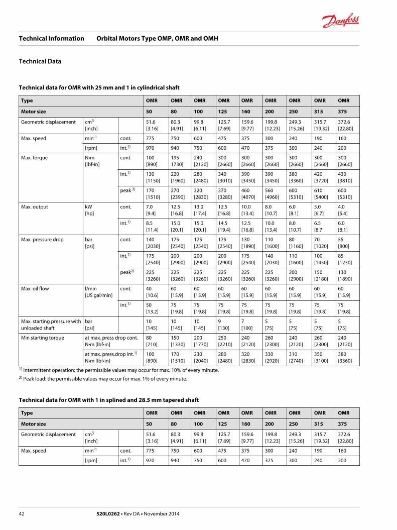
Technical data for OMR with 25 mm and 1 in cylindrical shaft
Type OMR OMR OMR OMR OMR OMR OMR OMR OMR
Motor size 50 80 100 125 160 200 250 315 375
Geometric displacement cm3
[inch]51.6[3.16]
80.3[4.91]
99.8[6.11]
125.7[7.69]
159.6[9.77]
199.8[12.23]
249.3[15.26]
315.7[19.32]
372.6[22.80]
Max. speed min-1 cont. 775 750 600 475 375 300 240 190 160
[rpm] int.1) 970 940 750 600 470 375 300 240 200
Max. torque N•m[lbf•in]
cont. 100[890]
1951730]
240[2120]
300[2660]
300[2660]
300[2660]
300[2660]
300[2660]
300[2660]
int.1) 130[1150]
220[1960]
280[2480]
340[3010]
390[3450]
390[3450]
380[3360]
420[3720]
430[3810]
peak 2) 170[1510]
270[2390]
320[2830]
370[3280]
460[4070]
560[4960]
600[5310]
610[5400]
600[5310]
Max. output kW[hp]
cont. 7.0[9.4]
12.5[16.8]
13.0[17.4]
12.5[16.8]
10.0[13.4]
8.0[10.7]
6.0[8.1]
5.0[6.7]
4.0[5.4]
int.1) 8.5[11.4]
15.0[20.1]
15.0[20.1]
14.5[19.4]
12.5[16.8]
10.0[13.4]
8.0[10.7]
6.5[8.7
6.0[8.1]
Max. pressure drop bar[psi]
cont. 140[2030]
175[2540]
175[2540]
175[2540]
130[1890]
110[1600]
80[1160]
70[1020]
55[800]
int.1) 175[2540]
200[2900]
200[2900]
200[2900]
175[2540]
140[2030]
110[1600]
100[1450]
85[1230]
peak2) 225[3260]
225[3260]
225[3260]
225[3260]
225[3260]
225[3260]
200[2900]
150[2180]
130[1890]
Max. oil flow l/min[US gal/min]
cont. 40[10.6]
60[15.9]
60[15.9]
60[15.9]
60[15.9]
60[15.9]
60[15.9]
60[15.9]
60[15.9]
int.1) 50[13.2]
75[19.8]
75[19.8]
75[19.8]
75[19.8]
75[19.8]
75[19.8]
75[19.8]
75[19.8]
Max. starting pressure withunloaded shaft
bar[psi]
10[145]
10[145]
10[145]
9[130]
7[100]
5[75]
5[75]
5[75]
5[75]
Min starting torque at max. press drop cont.N•m [lbf•in]
80[710]
150[1330]
200[1770]
250[2210]
240[2120]
260[2300]
240[2120]
260[2300]
240[2120]
at max. press.drop int.1)
N•m [lbf•in]100[890]
170[1510]
230[2040]
280[2480]
320[2830]
330[2920]
310[2740]
350[3100]
380[3360]
1) Intermittent operation: the permissible values may occur for max. 10% of every minute.2) Peak load: the permissible values may occur for max. 1% of every minute.
Technical data for OMR with 1 in splined and 28.5 mm tapered shaft
Type OMR OMR OMR OMR OMR OMR OMR OMR OMR
Motor size 50 80 100 125 160 200 250 315 375
Geometric displacement cm3
[inch]51.6[3.16]
80.3[4.91]
99.8[6.11]
125.7[7.69]
159.6[9.77]
199.8[12.23]
249.3[15.26]
315.7[19.32]
372.6[22.80]
Max. speed min-1 cont. 775 750 600 475 375 300 240 190 160
[rpm] int.1) 970 940 750 600 470 375 300 240 200
Technical Information Orbital Motors Type OMP, OMR and OMH
Technical Data
42 520L0262 • Rev DA • November 2014
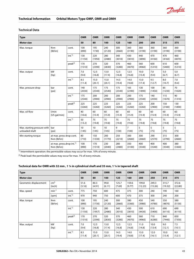
Type OMR OMR OMR OMR OMR OMR OMR OMR OMR
Motor size 50 80 100 125 160 200 250 315 375
Max. torque N•m[lbf•in]
cont. 100[890]
1951730]
240[2120]
300[2660]
360[3190]
360[3190]
360[3190]
360[3190]
360[3190]
int.1) 130[1150]
220[1950]
280[2480]
340[3010]
430[3810]
440[3890]
470[4160]
470[4160]
460[4070]
peak2) 170[1510]
270[2390]
320[2830]
370[3280]
460[4070]
560[4960]
600[5310]
610[5400]
600[5310]
Max. output kW[hp]
cont. 7.0[9.4]
12.5[16.8]
13.0[17.4]
12.5[16.8]
12.5[16.8]
10.0[13.4]
7.0[9.4]
5.0[6.7]
5.0[6.7]
int.1) 8.5[11.4]
15.0[20.1]
15.0[20.1]
14.5[19.4]
14.0[18.8]
13.0[17.4]
9.5[12.7]
8.0[10.7]
7.0[9.4]
Max. pressure drop bar[psi]
cont. 140[2030]
175[2540]
175[2540]
175[2540]
165[2390]
130[1890]
100[1450]
85[1230]
70[1020]
int.1) 175[2540]
200[2900]
200[2900]
200[2900]
200[2900]
175[2540]
140[2030]
115[1670]
90[1310]
peak2) 225[3260]
225[3260]
225[3260]
225[3260]
225[3260]
225[3260]
200[2900]
150[2180]
130[1890]
Max. oil flow l/min[US gal/min]
cont. 40[10.6]
60[15.9]
60[15.9]
60[15.9]
60[15.9]
60[15.9]
60[15.9]
60[15.9]
60[15.9]
int.1) 50[13.2]
75[19.8]
75[19.8]
75[19.8]
75[19.8]
75[19.8]
75[19.8]
75[19.8]
75[19.8]
Max. starting pressure withunloaded shaft
bar[psi]
10[145]
10[145]
10[145]
9[130]
7[100]
5[75]
5[75]
5[75]
5[75]
Min starting torque at max. press drop cont.N•m [lbf•in]
80[710]
150[1330]
200[1770]
250[2210]
300[2660]
300[2660]
290[2570]
315[2790]
300[2660]
at max. press.drop int.1)
N•m [lbf•in]100[890]
170[1510]
230[2040]
280[2480]
350[3100]
400[3540]
400[3540]
400[3540]
380[3360]
1) Intermittent operation: the permissible values may occur for max. 10% of every minute.2) Peak load: the permissible values may occur for max. 1% of every minute.
Technical data for OMR with 32 mm , 1 ¼ in cylindrical shaft and 35 mm, 1 ¼ in tapered shaft
Type OMR OMR OMR OMR OMR OMR OMR OMR OMR
Motor size 50 80 100 125 160 200 250 315 375
Geometric displacement cm3
[inch]51.6[3.16]
80.3[4.91]
99.8[6.11]
125.7[7.69]
159.6[9.77]
199.8[12.23]
249.3[15.26]
315.7[19.32]
372.6[22.80]
Max. speed min-1 cont. 775 750 600 475 375 300 240 190 160
[rpm] int.1) 970 940 750 600 470 375 300 240 200
Max. torque N•m[lbf•in]
cont. 100[890]
195[1730]
240[2120]
300[2660]
380[3360]
450[3980]
540[4780]
550[4870]
580[5130]
int.1) 130[1150]
220[1957]
280[2480]
340[3010]
430[3810]
500[4430]
610[5400]
690[6110]
690[6110]
peak2) 170[1510]
270[2390]
320[2830]
370[3280]
460[4070]
560[4960]
710[6280]
840[7440]
830[7350]
Max. output kW[hp]
cont. 7.0[9.4]
12.5[16.8]
13.0[17.4]
12.5[16.8]
12.5[16.8]
11.0[14.8]
10.0[13.4]
9.0[12.1]
7.5[10.1]
int.1) 8.5[11.4]
15.0[20.1]
15.0[20.1]
14.5[19.4]
14.0[18.8]
13.0[17.4]
12.0[16.1]
10.0[13.4]
9.0[12.1]
Technical Information Orbital Motors Type OMP, OMR and OMH
Technical Data
520L0262 • Rev DA • November 2014 43

Type OMR OMR OMR OMR OMR OMR OMR OMR OMR
Motor size 50 80 100 125 160 200 250 315 375
Max. pressure drop bar[psi]
cont. 140[2030]
175[2540]
175[2540]
175[2540]
175[2540]
175[2540]
175[2540]
135[1960]
115[1670]
int.1) 175[2540]
200[2900]
200[2900]
200[2900]
200[2900]
200[2900]
200[2900]
175[2540]
150[2180]
peak2) 225[3260]
225[3260]
225[3260]
225[3260]
225[3260]
225[3260]
225[3260]
210[3050]
175[2540]
Max. oil flow l/min[US gal/min]
cont. 40[10.6]
60[15.9]
60[15.9]
60[15.9]
60[15.9]
60[15.9]
60[15.9]
60[15.9]
60[15.9]
int.1) 50[13.2]
75[19.8]
75[19.8]
75[19.8]
75[19.8]
75[19.8]
75[19.8]
75[19.8]
75[19.8]
Max. starting pressure withunloaded shaft
bar[psi]
10[145]
10[145]
10[145]
9[130]
7[100]
5[75]
5[75]
5[75]
5[75]
Min starting torque at max. press drop cont.N•m [lbf•in]
80[710]
150[1330]
200[1770]
250[2210]
320[2830]
410[3630]
500[4430]
500[4430]
470[4170]
at max. press.drop int.1)
N•m [lbf•in]100[890]
170[1510]
230[2040]
280[2480]
370[3280]
460[4070]
550[4870]
660[5840]
570[5050]
1) Intermittent operation: the permissible values may occur for max. 10% of every minute.2) Peak load: the permissible values may occur for max. 1% of every minute.
Type Max. inlet pressure Max.return pressurewith drain line
OMR 50 - 375 bar[psi] cont
175[2540]
175[2540]
bar int.1)
[psi]200[2900]
200[2900]
bar peak2)
[psi]225[3260]
225[3260]
1) Intermittent operation: the permissible values may occur for max. 10% of every minute.2) Peak load: the permissible values may occur for max. 1% of every minute.
Technical Data for Parking Brake Motor OMR F, OMR NF and OMRW NF
Technical data for brake motor
Holding torque 1) N•m[lbf•in]
400[3540]
Min. release pressure 2) bar[psi]
21[305]
Max. pressure in brake line bar[psi]
200[2900]
1) This brake is to be used only as a passive parking brake. It may not be used for dynamic braking.2) Brake motors must always have a drain line. The brake release pressure is the difference between the pressure in the brake release line and thepressure in the drain line.
Function
In normal condition where there is no pressure on the integrated brake in OMR, i.e. the brake is applied.The brake is released when hydraulic pressure of 21 bar [300psi] min. is applied to the brake release port(1).
Technical Information Orbital Motors Type OMP, OMR and OMH
Technical Data
44 520L0262 • Rev DA • November 2014
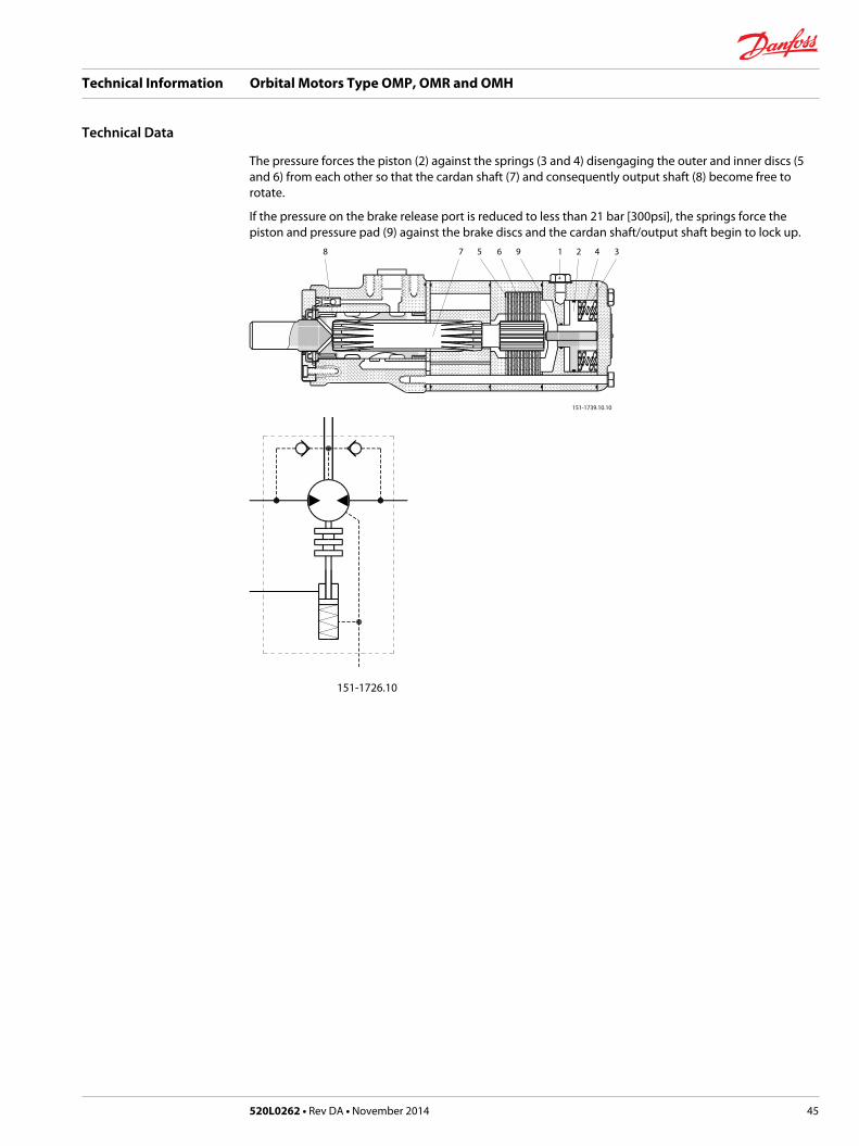
The pressure forces the piston (2) against the springs (3 and 4) disengaging the outer and inner discs (5and 6) from each other so that the cardan shaft (7) and consequently output shaft (8) become free torotate.
If the pressure on the brake release port is reduced to less than 21 bar [300psi], the springs force thepiston and pressure pad (9) against the brake discs and the cardan shaft/output shaft begin to lock up.
8 7 5 6 9 1 2 4 3
151-1739.10.10
151-1726.10
Technical Information Orbital Motors Type OMP, OMR and OMH
Technical Data
520L0262 • Rev DA • November 2014 45

OMR with High Pressure Shaft Seal (HPS)
OMR with HPS, without check valves and without drain connection:
The shaft seal pressure equals the average of input pressure and return pressure
151-1743.10
OMR with HPS, check valves and with drain connection:
The shaft seal pressure equals the pressure in the drain line.
OMR with HPS, check valves and without drain connection:
The pressure on the shaft seal never exceeds the pressure in the return line.
151-320.10
Max. permissible shaft seal pressure
psi3600
3000
2400
1800
1200
600
0
bar250
200
150
100
50
00 100 200 300 400 500 600 700 800
151-1856.10
Ø25 mm - Ø1” -Ø1 splined shaft
int. operation1)
max.min-1
(rpm)
OMR with Standard Shaft Seal
OMR with standard shaft seal, check valves and without use of drain connection:
The pressure on the shaft seal never exceeds the pressure in the return line
151-320.10
OMR with standard shaft seal, check valves and with drain connection:
Technical Information Orbital Motors Type OMP, OMR and OMH
Technical Data - Max. Permissible Shaft Seal Pressure
46 520L0262 • Rev DA • November 2014

The shaft seal pressure equals the pressure on the drain line.
Max. return pressure without drain line or max. pressure in the drain line
psi
2000
1600
1200
800
400
0
bar
150
125
100
75
50
25
00 100 200 300 400 500 600
151-1563.10
int. operation1)
int. operation1)
min-1
(rpm)
Ø25 mm - Ø1” -1” splined - 1” and 28.5 mm tapered shaft
Ø32 mm shaftmax.
1) Intermittent operation: the permissible values may occur for max. 10% of every minute.
Technical Information Orbital Motors Type OMP, OMR and OMH
Technical Data - Max. Permissible Shaft Seal Pressure
520L0262 • Rev DA • November 2014 47

Pressure Drop in Motor
The curve applies to an unloaded motor shaft and an oil viscosity of 35 mm2/s [165 SUS]
psi
400
350
300
250
200
150
100
50
0
bar30
25
20
15
10
5
00 10 20 30 40 50 60 70 80 l/min
0 2 4 6 8 10 12 14 16 18 20 US gal/min
151-1566.10
Q
Q
pp
Oil flow in drain line
The table shows the max. oil flow in the drain line at a return pressure less than 5-10 bar [75-150 psi].
Pressure drop bar [psi] Viscositymm²/s [SUS]
Oil flow in drain line l/min [US gal/min]
100 [1450] 20 [100] 2.5 [0.66]
35 [165] 1.8 [0.78]
140 [2030] 20 [100] 3.5 [0.93]
35 [165] 2.8 [0.74]
Direction of Shaft Rotation
151-1836.10
Permissible Shaft Loads for OMR
The permissible radial shaft load (PR) depends on• Speed (n)
• Distance (L) from the point of load to the mounting flange
• Mounting flange version
• Shaft version
Mounting flange 4-oval flange**2-hole oval flange(European version)
4-hole oval flange Square flange**2-hole oval flange(US-version)
Technical Information Orbital Motors Type OMP, OMR and OMH
Technical Data
48 520L0262 • Rev DA • November 2014

Shaft version 25 mm cylindrical shaft1 in cylindrical shaft1 in splined shaft
32 mm cylindrical shaft 25 mm cylindrical shaft
Permissible shaft load (PR) - l in mm 800 250000 N*n 95 + L
800 187500 N*n 95 + L
800 250000 N*n 101 + L
Permissible shaft load (PR) - l in inch 800 2215 lbf*n 3.74 + L
800 1660 lbf*n 3.74 + L
800 2215 lbf*n 3.98 + L
* n≥ 200 min-1 [rpm]; ≤ 55 mm [2.2 in]n< 200 min-1 [rpm]; = > PRmax = 8000 N [1800 lbf]** For both European and US-version
151-1203.10
30 [1.18]
24 [0.94]
24 [0.94]
330 lbf1500 N
2000 N440 lbf
A-2 (European-version)
A-2 (US-version)
A-4
PR
PR
PR
C
lbf
2000
1600
1200
800
400
0
N9000
8000
6000
4000
2000
00 200 400 600 800 min-1
(rpm)
--------- cylindrical shaft 32 mm [1.26 in]
______ other shaft versions
The curve shows the relation between PR and n• when l = 30 mm [1.18 in] for motors with A2 (European version) and A4 oval mounting flange
• when l = 24 mm [0.94 in] for motors with square mounting flange and A2
• (US version)
For applications with special performance requirements we recommend OMR with the output shaftrunning in needle bearings.
Permissible Shaft Load for OMR N and OMR NF with Needle Bearings
4400
4000
3600
3200
2800
2400
2000
1600
1200
800
400
0
20000
18000
16000
14000
12000
10000
8000
6000
4000
2000
0
151-2112.10
120 110 100 90 80 70 60 50 40 30 20 10 0 -10 -20 -30 mm
4 3 2 1 0 -1 in
lbf NPrad. Prad.
Pmax.
Pmax.
=
=
2000 N450 lbf
1500 N335 lbf
0 -
50 min-1
200 min-1
800 min-1
A
+
Technical Information Orbital Motors Type OMP, OMR and OMH
Technical Data
520L0262 • Rev DA • November 2014 49
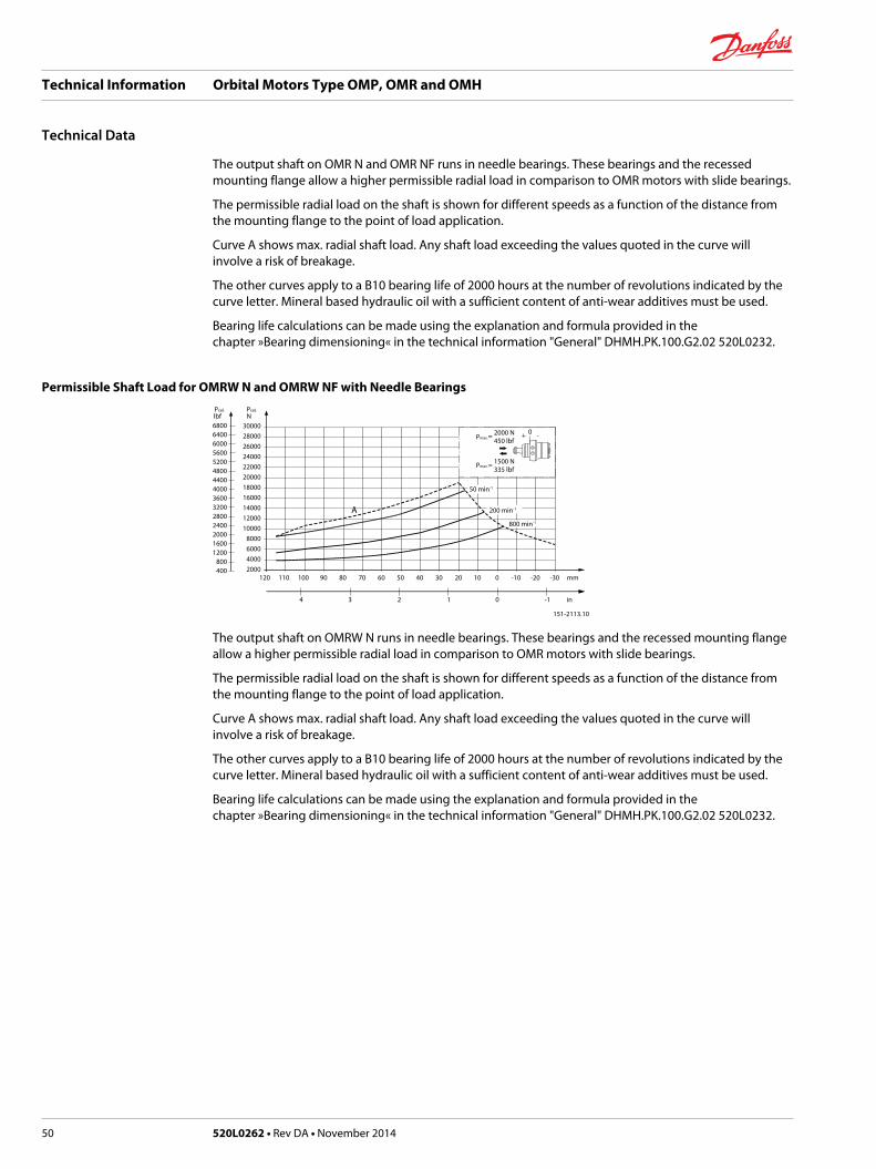
The output shaft on OMR N and OMR NF runs in needle bearings. These bearings and the recessedmounting flange allow a higher permissible radial load in comparison to OMR motors with slide bearings.
The permissible radial load on the shaft is shown for different speeds as a function of the distance fromthe mounting flange to the point of load application.
Curve A shows max. radial shaft load. Any shaft load exceeding the values quoted in the curve willinvolve a risk of breakage.
The other curves apply to a B10 bearing life of 2000 hours at the number of revolutions indicated by thecurve letter. Mineral based hydraulic oil with a sufficient content of anti-wear additives must be used.
Bearing life calculations can be made using the explanation and formula provided in thechapter »Bearing dimensioning« in the technical information "General" DHMH.PK.100.G2.02 520L0232.
Permissible Shaft Load for OMRW N and OMRW NF with Needle Bearings
680064006000560052004800440040003600320028002400200016001200
800400
3000028000260002400022000200001800016000140001200010000
8000600040002000
151-2113.10
120 110 100 90 80 70 60 50 40 30 20 10 0 -10 -20 -30 mm
4 3 2 1 0 -1 in
A
lbf NPrad. Prad.
Pmax.
Pmax.
=
=
2000 N450 lbf
1500 N335 lbf
0+ -
50 min-1
200 min-1
800 min-1
The output shaft on OMRW N runs in needle bearings. These bearings and the recessed mounting flangeallow a higher permissible radial load in comparison to OMR motors with slide bearings.
The permissible radial load on the shaft is shown for different speeds as a function of the distance fromthe mounting flange to the point of load application.
Curve A shows max. radial shaft load. Any shaft load exceeding the values quoted in the curve willinvolve a risk of breakage.
The other curves apply to a B10 bearing life of 2000 hours at the number of revolutions indicated by thecurve letter. Mineral based hydraulic oil with a sufficient content of anti-wear additives must be used.
Bearing life calculations can be made using the explanation and formula provided in thechapter »Bearing dimensioning« in the technical information "General" DHMH.PK.100.G2.02 520L0232.
Technical Information Orbital Motors Type OMP, OMR and OMH
Technical Data
50 520L0262 • Rev DA • November 2014

Function Diagrams
OMR 50lbf• in Nm
1200
1000
800
600
400
200
0
140
120
100
80
60
40
20
0
0 100 200 300 400 500 600 700 800 900 1000
151-1172.10
min-1
(rpm)
Q=5
l/m
in[1
.3 U
S ga
l/min
]
10 l/
min
[2.6
US
gal/m
in]
20 l/
min
[5.3
US
gal/m
in]
30 l/
min
[7.9
US
gal/m
in]
15 l/
min
[4.0
US
gal/m
in]
40 l/
min
[10.
6 U
S ga
l/min
]
25 l/
min
[6.6
US
gal/m
in]
35 l/
min
[9.2
US
gal/m
in]
45 l/
min
[11.
9 U
S ga
l/min
]
Q=5
0 l/m
in[1
3.2
US
gal/m
in]
∆ p=175 bar
∆ p= 30 bar
160 bar
1450 psi
2030 psi
1740 psi
2320 psi
2540 psi
80 bar
440 psi
870 psi
1160 psi60 bar
100 bar
120 bar
140 bar
N=0.5kW
4kW
N=8kW
1kW
6kW
75%
70%
6hp 8hp
0.5hp1hp
N=10hp
η t =80%
η t =60%
4hp
2kW2hp
OMR 80lbf• in Nm
2000
1800
1600
1400
1200
1000
800
600
400
200
0
220
200
180
160
140
120
100
80
60
40
20
0
151- 299.10
min-1
(rpm)
Q=5
l/m
in[1
.3 U
S ga
l/min
]10
l/m
in[2
.6 U
S ga
l/min
]
20 l/
min
[5.3
US
gal/m
in]
30 l/
min
[7.9
US
gal/m
in]
40 l/
min
[10.
6 U
S ga
l/min
]
50 l/
min
[13.
2 U
S ga
l/min
]
60 l/
min
[15.
9 U
S ga
l/min
]
70 l/
min
[18.
5US
gal/m
in]
Q=7
5 l/m
in[1
9.8
US
gal/m
in]
∆ p=200 bar
∆ p= 30 bar
175 bar
1450 psi
2030 psi
1740 psi
2540 psi
2900 psi
80 bar
440 psi
870 psi
1160 psi60 bar
100 bar
120 bar
140 bar
N=1kW
4kW
12kW
10kW
N=14kW
8kW6kW
75%70%
6hp8hp
16hp
10hp
14hp18hp12hp
η t =83%
η t =60%
80%
N=1hp
4hp
2kW2hp
0 100 200 300 400 500 600 700 800 900 1000
OMR 100lbf• in Nm
2400
2000
1600
1200
800
400
0
280
240
200
160
120
80
40
0
0 100 200 300 400 500 600 700 800
151-300.10
min-1
(rpm)
Q=5
l/m
in[1
.3 U
S ga
l/min
]10
l/m
in[2
.6 U
S ga
l/min
]
20 l/
min
[5.3
US
gal/m
in]
30 l/
min
[7.9
US
gal/m
in]
40 l/
min
[10.
6 U
S ga
l/min
]
50 l/
min
[13.
2 U
S ga
l/min
]
60 l/
min
[15.
9 U
S ga
l/min
]
70 l/
min
[18.
5US
gal/m
in]
Q=7
5 l/m
in[1
9.8
US
gal/m
in]
∆ p=200 bar
∆ p= 30 bar
175 bar
1450 psi
2030 psi
1740 psi
2540 psi
2900 psi
80 bar
440 psi
870 psi
1160 psi60 bar
100 bar
120 bar
140 bar
N=1kW
4kW
10kW
N=14kW12kW
8kW6kW
75%
70%
80%
6hp
8hp 10hp
14hp12hp
16hp N= 18hp
η t =84%
η t =60%
N=1hp
4hp2kW
2hp
Technical Information Orbital Motors Type OMP, OMR and OMH
Function Diagrams
520L0262 • Rev DA • November 2014 51

OMR 125lbf• in Nm
3200
2800
2400
2000
1600
1200
800
400
0
360
320
280
240
200
160
120
80
40
0
151-1395.10
min-1
(rpm)
Q=5
l/m
in[1
.3 U
S ga
l/min
]10
l/m
in[2
.6 U
S ga
l/min
]
20 l/
min
[5.3
US
gal/m
in]
30 l/
min
[7.9
US
gal/m
in]
40 l/
min
[10.
6 U
S ga
l/min
]
50 l/
min
[13.
2 U
S ga
l/min
]
60 l/
min
[15.
9 U
S ga
l/min
]
70 l/
min
[18.
5US
gal/m
in]
Q=7
5 l/m
in[1
9.8
US
gal/m
in]
∆ p=200 bar
∆ p= 30 bar
175 bar
1450 psi
2030 psi
1740 psi
2540 psi
2900 psi
80 bar
440 psi
870 psi
1160 psi60 bar
100 bar
120 bar
140 bar
N=1kW
4kW
10kW
N=12kW
8kW
6kW
75%70%
80%
6hp
8hp 10hp
14hp
12hp
16hp
N=18hp
η t =83%
η t =60%
N=1hp
4hp2kW
2hp
0 50 100 150 200 250 300 350 400 450 500 550 600
OMR 160lbf• in Nm
4000
3600
3200
2800
2400
2000
1600
1200
800
400
0
440
400
360
320
280
240
200
160
120
80
40
0
0 50 100 150 200 250 300 350 400 450 500
151-1044.10
min-1
(rpm)
Q=5
l/m
in[1
.3 U
S ga
l/min
]10
l/m
in[2
.6 U
S ga
l/min
]
20 l/
min
[5.3
US
gal/m
in]
30 l/
min
[7.9
US
gal/m
in]
40 l/
min
[10.
6 U
S ga
l/min
]
50 l/
min
[13.
2 U
S ga
l/min
]
60 l/
min
[15.
9 U
S ga
l/min
]
70 l/
min
[18.
5US
gal/m
in]
Q=7
5 l/m
in[1
9.8
US
gal/m
in]
∆ p=200 bar
∆ p= 30 bar
175 bar
1450 psi
2030 psi
1740 psi
2540 psi
2900 psi
80 bar
440 psi
870 psi
1160 psi60 bar
100 bar
120 bar
140 bar
N=1kW
4kW
10kW
N= 12kW
N= 16hp
8kW
6kW
75%70%
80%
6hp8hp
10hp
12hp 14hp
η t =87%
η t =60%
N=1hp
4hp
2kW
2hp
OMR 200lbf• in Nm
5000
4500
4000
3500
3000
2500
2000
1500
1000
500
0
550
500
450
400
350
300
250
200
150
100
50
0
0 50 100 150 200 250 300 350 400
151-1396.10
min-1
(rpm)
Q=5
l/m
in[1
.3 U
S ga
l/min
]10
l/m
in[2
.6 U
S ga
l/min
]
20 l/
min
[5.3
US
gal/m
in]
30 l/
min
[7.9
US
gal/m
in]
40 l/
min
[10.
6 U
S ga
l/min
]
50 l/
min
[13.
2 U
S ga
l/min
]
60 l/
min
[15.
9 U
S ga
l/min
]
70 l/
min
[18.
5US
gal/m
in]
Q=7
5 l/m
in[1
9.8
US
gal/m
in]
∆ p=200 bar
∆ p= 30 bar
175 bar
1520 psi
2030 psi
1740 psi
2540 psi
2900 psi
80 bar
440 psi
870 psi
1160 psi60 bar
105 bar
120 bar
140 bar
N=1kW
4kW
10kW
N= 12kW 14hp
8kW
6kW
75%70%
6hp8hp
10hp
12hp
η t =80%
η t =60%
N=1hp
4hp
2kW
2hp
Technical Information Orbital Motors Type OMP, OMR and OMH
Function Diagrams
52 520L0262 • Rev DA • November 2014

OMR 250lbf• in Nm
6000
5500
5000
4500
4000
3500
3000
2500
2000
1500
1000
500
0
650
600
550
500
450
400
350
300
250
200
150
100
50
0
151-1119.10
min-1
(rpm)
Q=5
l/m
in[1
.3 U
S ga
l/min
]10
l/m
in[2
.6 U
S ga
l/min
]
20 l/
min
[5.3
US
gal/m
in]
30 l/
min
[7.9
US
gal/m
in]
40 l/
min
[10.
6 U
S ga
l/min
]
50 l/
min
[13.
2 U
S ga
l/min
]
60 l/
min
[15.
9 U
S ga
l/min
]
70 l/
min
[18.
5US
gal/m
in]
Q=7
5 l/m
in[1
9.8
US
gal/m
in]
∆ p=200 bar
∆ p= 30 bar
175 bar
1450 psi
2030 psi
1600 psi
2540 psi
2900 psi
80 bar
440 psi
870 psi
1160 psi
60 bar
100 bar110 bar
140 bar
N=1kW
4kW
N=10kW
8kW
6kW
75% 70%
80%
6hp
8hp 10hp
N= 12hp
η t =85%
η t =60%
N=1hp
4hp2kW
2hp
0 25 50 75 100 125 150 175 200 225 250 275 300 325
OMR 315lbf• in Nm
6500
6000
5500
5000
4500
4000
3500
3000
2500
2000
1500
1000
500
0
720
640
560
480
400
320
240
160
80
0
0 25 50 75 100 125 150 175 200 225 250
151-809.10
min-1
(rpm)
Q=5
l/m
in[1
.3 U
S ga
l/min
]
10 l/
min
[2.6
US
gal/m
in]
20 l/
min
[5.3
US
gal/m
in]
30 l/
min
[7.9
US
gal/m
in]
40 l/
min
[10.
6 U
S ga
l/min
]
50 l/
min
[13.
2 U
S ga
l/min
]
60 l/
min
[15.
9 U
S ga
l/min
]
70 l/
min
[18.
5US
gal/m
in]
Q=7
5 l/m
in[1
9.8
US
gal/m
in]
160 bar
∆ p= 30 bar
940 psi
1810 psi
2320 psi135 bar1960 psi
∆ p=175 bar2540 psi
440 psi
950 psi45 bar
65 bar
125 bar
1300 psi90 bar
1160 psi80 barN=1kW
4kW
6kW
N=8kW
75%80%
8hp10hp
6hp
N= 12hp
η t =83%
η t =60%70%
N=1hp
4hp
2kW2hp
OMR 375lbf• in Nm
6500
6000
5500
5000
4500
4000
3500
3000
2500
2000
1500
1000
500
0
700
650
600
550
500
450
400
350
300
250
200
150
100
50
0
0 25 50 75 100 125 150 175 200 225
151-1385.11
min-1
(rpm)
Q=5
l/m
in[1
.3 U
S ga
l/min
]
10 l/
min
[2.6
US
gal/m
in]
20 l/
min
[5.3
US
gal/m
in]
30 l/
min
[7.9
US
gal/m
in]
40 l/
min
[10.
6 U
S ga
l/min
]
50 l/
min
[13.
2 U
S ga
l/min
]
60 l/
min
[15.
9 U
S ga
l/min
]
70 l/
min
[18.
5US
gal/m
in]
Q=7
5 l/m
in[1
9.8
US
gal/m
in]
∆ p=150 bar
∆ p= 30 bar
115 bar
1450 psi
1890 psi
1230 psi
1670 psi
2180 psi
70 bar
440 psi
800 psi
10200 psi55 bar
580 psi40 bar
100 bar
85 bar
130 bar
N=1kW
4kW
N=8kW
6kW
75%
70%80%
6hp
8hp
10hpN= 12hp
η t =85%
η t =60%
N=1hp
4hp
2kW
2hp
Explanation of function diagram use, basis and conditions can be found in Speed, Torque and Output onpage 8.• Continuous range
• Intermittent range (max. 10% operation every minute)
Max. permissible continuous/intermittent pressure drop for the actual shaft version can be found in Technical data for OMR with 25 mm and 1 in cylindrical shaft on page 42.
Intermittent pressure drop and oil flow must not occur simultaneously.
Technical Information Orbital Motors Type OMP, OMR and OMH
Function Diagrams
520L0262 • Rev DA • November 2014 53

Shaft Version
8.000 [0.315]7.964 [0.314]
43.8 [1.724]42.5 [1.673]
max. 6 [0.24]min. 18 [0.71]
R0.5[0.020]
45˚
32.0 [1.260]31.7 [1.248]
6.40 [0.252]4.40 [0.173]
M8
Ø28
.56
[1.1
24]
28.0
[1.1
02]
27.7
[1.0
90]
Ø25
.015
[0.9
85]
Ø25
.002
[0.9
84]
D
A-A
6.40 [0.252]6.35 [0.250]
28.1
9 [1
.110
]27
.93
[1.1
00]
E
A-A
6.40 [0.252]6.35 [0.250]
28.1
9 [1
.110
]27
.93
[1.1
00]
F
A-A
A
A
A
43.8 [1.724]42.5 [1.673]
max. 6 [0.24]
min. 18 [0.71]
R0.5[0.020]
45˚
31.75 [1.250]31.45 [1.238]
31.75 [1.250]31.45 [1.238]
5.5 [0.217]3.5 [0.138]
5.5 [0.217]3.5 [0.138]
M8
Ø28
.56
[1.1
24]
Ø25
.40
[1.0
00]
Ø25
.38
[0.9
99]
Ø25
.40
[1.0
00]
Ø25
.38
[0.9
99]
B
A
A
38.8 [1.528]36.8 [1.448]
max. 6 [0.24]
¼ -20 UNC
min. 18 [0.71]
R0.5[0.020]
45˚
Ø28
.56
[1.1
24]
C
A
A
151-1846.12
A: Cylindrical shaft25 mm
D: Parallel keyA8 • 7 • 32DIN 6885
B: Cylindrical shaft 1 in E: Parallel key¼ • ¼ • 1 ¼ inB.S. 46
US version
C: Cylindrical shaft1 in
F: Parallel key¼ • ¼ • 1 ¼ inB.S. 46
Technical Information Orbital Motors Type OMP, OMR and OMH
Shaft Version
54 520L0262 • Rev DA • November 2014

10.00 [0.394]9.964 [0.392]
max. 6 [0.24]min. 18 [0.71]
max. 7 [0.276]
3/8-16 UNC
min. 26.5 [1.043]
R0.5[0.020]
R0.5[0.020]
R0.5[0.020]
45˚
45˚
45˚
45.0 [1.772]44.7 [1.760]
56.95 [2.242]55.35 [2.179]
5.50 [0.217]4.50 [0.177]
M8
35.0
0 [1
.38]
34.8
0 [1
.37]
Ø32
.018
[1.2
61]
Ø32
.002
[1.2
60]
Ø35
.0 [1
.378
]G
H
A-A
A-A
A-A
*21.540 [0.848]*21.400 [0.843]
6x60˚
6.27
5 [0
.247
]6.
201
[0.2
44]
5.00 [0.197]4.97 [0.196]
D
max. 6 [0.24]min. 18 [0.71]
27.4 [1.079]25.4 [1.000]
R max. 42.5 [1.673]
43.8 [1.724]42.5 [1.673]
1.2 [0.039]x45˚0.8 [0.031]x45˚
M8
Ø25
.348
[0.9
98]
Ø25
.298
[0.9
96]
Ø28
.56
[1.1
24]
E
7.963 [0.314]7.938 [0.313]
31.75 [1.250]31.37 [1.235]
46.95 [1.848]45.35 [1.785]
151-1851.12
Ø35
[1.3
78]
Ø31
.75
[1.2
50]
Ø31
.73
[1.2
49]
35.3
7 [1
.393
]35
.04
[1.3
80]
F
A
A
A
A
A
A
D: Cylindrical shaft32 mm
G: Parallel keyA10 • 8 • 45DIN 6885
US version
E: Cylindrical shaft1 ¼ in
H: Parallel key5⁄16 5⁄16 1 ¼ inB.S. 46
F: Involute splined shaftB.S. 2059 (SAE 6 B)Straight-sided,bottom fitting, deep.Fit 2Nom. size 1 in*Deviates fromB.S. 2059 (SAE 6 B)
Technical Information Orbital Motors Type OMP, OMR and OMH
Shaft Version
520L0262 • Rev DA • November 2014 55
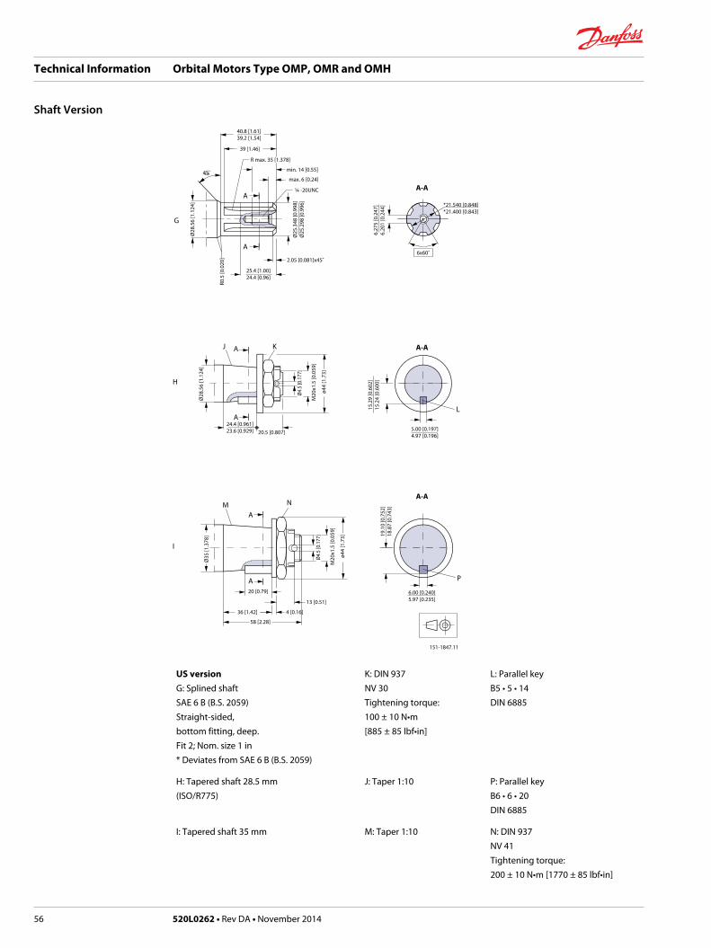
40.8 [1.61]39.2 [1.54]
max. 6 [0.24]
min. 14 [0.55]45˚
25.4 [1.00]24.4 [0.96]
Ø25
.348
[0.9
98]
Ø25
.298
[0.9
96]
Ø28
.56
[1.1
24]
A-A
A-A
A-A
*21.540 [0.848]*21.400 [0.843]
6x60˚
6.27
5 [0
.247
]6.
201
[0.2
44]
5.00 [0.197]4.97 [0.196]
6.00 [0.240]5.97 [0.235]
151-1847.11
15.2
9 [0
.602
]15
.24
[0.6
00]
I
L
P
J K
M N
A
G
A
A
A
A
A
¼ -20UNC
R0.5
[0.0
20]
13 [0.51]
20 [0.79]
36 [1.42] 4 [0.16]
58 [2.28]
R max. 35 [1.378]
39 [1.46]
2.05 [0.081]x45˚
19.1
0 [0
.752
]18
.87
[0.7
43]
Ø28
.56
[1.1
24]
24.4 [0.961]23.6 [0.929] 20.5 [0.807]
Ø35
[1.3
78]
Ø4.
5 [0
.177
]
M20
x1.5
[0.0
59]
ø44
[1.7
3]Ø
4.5
[0.1
77]
M20
x1.5
[0.0
59]
ø44
[1.7
3]
H
US versionG: Splined shaftSAE 6 B (B.S. 2059)Straight-sided,bottom fitting, deep.Fit 2; Nom. size 1 in* Deviates from SAE 6 B (B.S. 2059)
K: DIN 937NV 30Tightening torque:100 ± 10 N•m[885 ± 85 lbf•in]
L: Parallel keyB5 • 5 • 14DIN 6885
H: Tapered shaft 28.5 mm(ISO/R775)
J: Taper 1:10 P: Parallel keyB6 • 6 • 20DIN 6885
I: Tapered shaft 35 mm M: Taper 1:10 N: DIN 937NV 41Tightening torque:200 ± 10 N•m [1770 ± 85 lbf•in]
Technical Information Orbital Motors Type OMP, OMR and OMH
Shaft Version
56 520L0262 • Rev DA • November 2014

45˚
35.6 [1.402]34.4 [1.354]
17.1
6 [0
.676
]16
.94
[0.6
67]
31.7
75 [1
.251
]31
.725
[1.2
49]
Ø35
[1.3
8]L
A-A
7.96 [0.3135]7.94 [0.3125]
J
KA
A
Ø4
[0.1
5]
54.4 [2.142]53.8 [2.118]
31.75 [1.250]31.37 [1.235] 5 [0.20]
12.7 [0.50]
151-1848.11
M
J: Tapered shaft 1 1/4 in K: Cone 1:8SAE J501
L: 1 - 20 UNEFAcross flats 1 7/16Tightening torque:200 ± 10 Nm [1770 ± 85 lbf·in]
M: Parallel key5/16 • 5/16 • 1 1/4SAE J501
Technical Information Orbital Motors Type OMP, OMR and OMH
Shaft Version
520L0262 • Rev DA • November 2014 57

Port Thread Versions
D
G
A
H
B
E
F
J
C
I
max. Ø21.5 [0.846] Ø30.5 [1.200]Ø29.5 [1.161]
2x max 21.5 [0.84]
max
. 27
[1.0
6]
min
. 16.
7 [0
.657
]
1.0
[0.0
4]
min
. 15
[0.5
9]
Ø18.5 [0.728]Ø17.5 [0.689]
min
. 12
[0.4
7]
max
. 0.6
[0.0
24]
12.2
[0.4
73]
11.8
[0.4
65]
151-1844.11
A: G main ports B: UNF main ports C: NPTF main ports
G: ISO 228/1 - G½ H: 7/8 - 14 UNFO-ring boss port
I: ½ - 14 NPTF
D: G drain port F: UNF drain port
E: ISO 228/1 - G¼O-ring boss port
J: 7/16 - 20 UNF
Manifold Mount
European version
18 [0.71] 18 [0.71]
151-2135.10
20 [0
.79]
20 [0
.79]
20 [0
.79]
20 [0
.79]
36 [1
.42]
L
L: see dimensional drawing for given OMR motor: Dimensions-European version on page 59 and Dimension-US Version on page 65
Technical Information Orbital Motors Type OMP, OMR and OMH
Port Thread Versions
58 520L0262 • Rev DA • November 2014
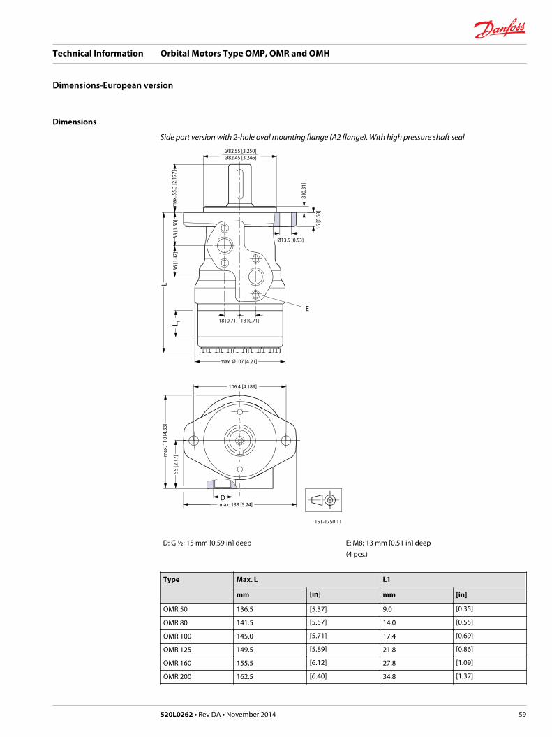
Dimensions
Side port version with 2-hole oval mounting flange (A2 flange). With high pressure shaft seal
Ø82.55 [3.250]Ø82.45 [3.246]
Ø13.5 [0.53]
18 [0.71]18 [0.71]
max. Ø107 [4.21]
106.4 [4.189]
max. 133 [5.24]
151-1750.11
16 [0
.63]
8 [0
.31]
36 [1
.42]
38 [1
.50]
max
. 55.
3 [2
.177
]55
[2.1
7]max
. 110
[4.3
3]
E
LL 1
D
D: G ½; 15 mm [0.59 in] deep E: M8; 13 mm [0.51 in] deep(4 pcs.)
Type Max. L L1
mm [in] mm [in]
OMR 50 136.5 [5.37] 9.0 [0.35]
OMR 80 141.5 [5.57] 14.0 [0.55]
OMR 100 145.0 [5.71] 17.4 [0.69]
OMR 125 149.5 [5.89] 21.8 [0.86]
OMR 160 155.5 [6.12] 27.8 [1.09]
OMR 200 162.5 [6.40] 34.8 [1.37]
Technical Information Orbital Motors Type OMP, OMR and OMH
Dimensions-European version
520L0262 • Rev DA • November 2014 59

Type Max. L L1
mm [in] mm [in]
OMR 250 171.5 [6.75] 43.5 [1.71]
OMR 315 182.5 [7.19] 54.8 [2.16]
OMR 375 192.7 [7.59] 65.0 [2.56]
Side port version with 2-hole oval mounting flange (A2 flange). With check valves and drain connection. Withhigh pressure shaft seal.
Ø82.55 [3.250]Ø82.45 [3.246]
Ø13.5 [0.53]
18 [0.71]18 [0.71]
max. Ø107 [4.21]
106.4 [4.189]
max. 133 [5.24]
151-1845.11
16 [0
.63]
8 [0
.31]
38 [1
.50]
36 [1
.42]
max
. 55.
3 [2
.177
]m
ax. 6
[0.2
4]
55 [2
.17]
max
. 110
[4.3
3]
E
C
LL 1
D
C: Drain connectionG ¼; 15 mm [0.47 in] deep
D: G ½; 15 mm [0.59 in] deep
E: M8; 13 mm [0.51 in] deep(4 pcs.)
Technical Information Orbital Motors Type OMP, OMR and OMH
Dimensions-European version
60 520L0262 • Rev DA • November 2014
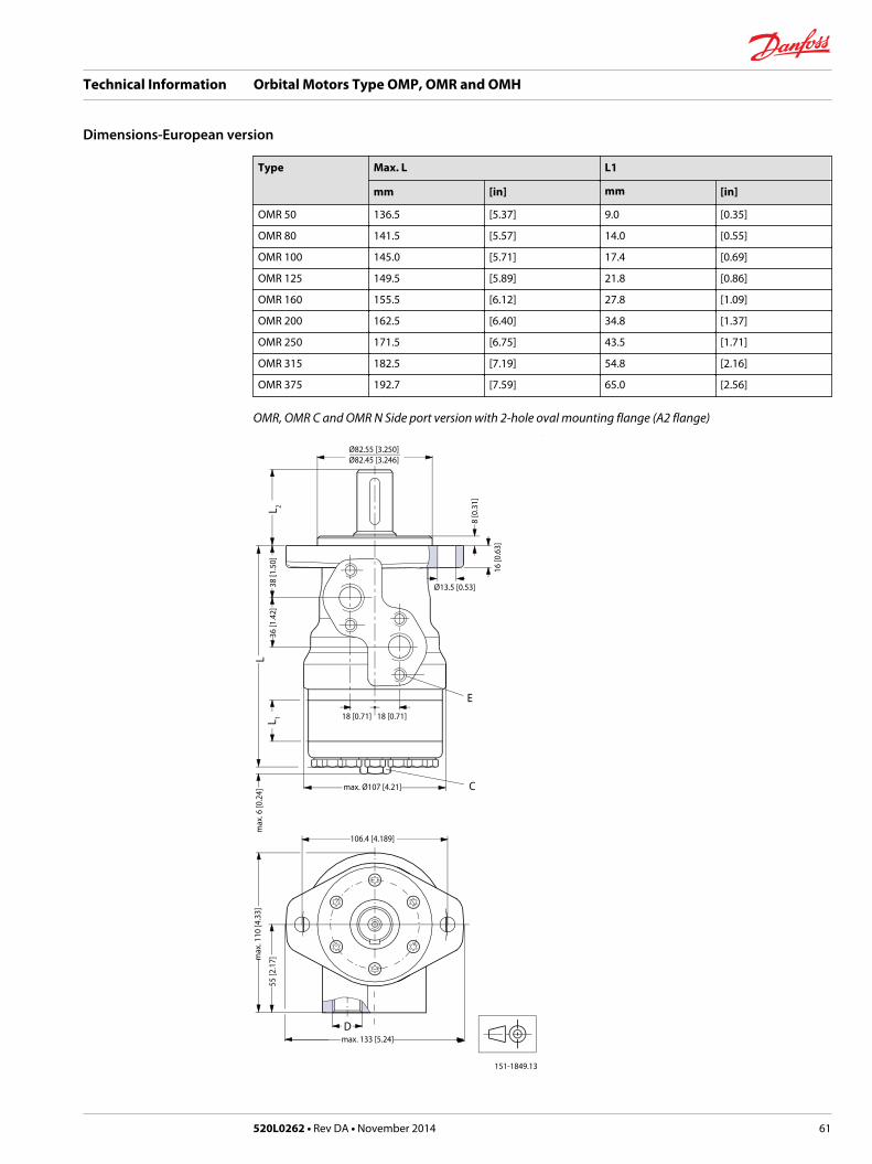
Type Max. L L1
mm [in] mm [in]
OMR 50 136.5 [5.37] 9.0 [0.35]
OMR 80 141.5 [5.57] 14.0 [0.55]
OMR 100 145.0 [5.71] 17.4 [0.69]
OMR 125 149.5 [5.89] 21.8 [0.86]
OMR 160 155.5 [6.12] 27.8 [1.09]
OMR 200 162.5 [6.40] 34.8 [1.37]
OMR 250 171.5 [6.75] 43.5 [1.71]
OMR 315 182.5 [7.19] 54.8 [2.16]
OMR 375 192.7 [7.59] 65.0 [2.56]
OMR, OMR C and OMR N Side port version with 2-hole oval mounting flange (A2 flange)
Ø82.55 [3.250]Ø82.45 [3.246]
Ø13.5 [0.53]
18 [0.71]18 [0.71]
max. Ø107 [4.21]
106.4 [4.189]
max. 133 [5.24]
151-1849.13
16 [0
.63]
8 [0
.31]
36 [1
.42]
38 [1
.50]
max
. 6 [0
.24]
55 [2
.17]m
ax. 1
10 [4
.33]
E
C
LL 1
L 2
D
Technical Information Orbital Motors Type OMP, OMR and OMH
Dimensions-European version
520L0262 • Rev DA • November 2014 61

C: Drain connectionG ¼; 12 mm [0.47 in] deep
D: G ½; 15 mm [0.59 in] deep
E: M8; 13 mm [0.51 in] deep(4 pcs.)
Output shaft.max. L2
mm [in]
Cylindrical shaft 32 mm [1.26 in] 68.3 [2.69]
Cylindrical shaft 25 mm [0.98 in] 55.3 [2.18]
Tapered shaft 28.56 mm [1.12 in] 56.3 [2.19]
Type Max. L L1
mm [in] mm [in]
OMR 50 136.5 [5.37] 9.0 [0.35]
OMR 80 141.5 [5.57] 14.0 [0.55]
OMR 100 145.0 [5.71] 17.4 [0.69]
OMR 125 149.5 [5.89] 21.8 [0.86]
OMR 160 155.5 [6.12] 27.8 [1.09]
OMR 200 162.5 [6.40] 34.8 [1.37]
OMR 250 171.5 [6.75] 43.5 [1.71]
OMR 315 182.5 [7.19] 54.8 [2.16]
OMR 375 192.7 [7.59] 65.0 [2.56]
Technical Information Orbital Motors Type OMP, OMR and OMH
Dimensions-European version
62 520L0262 • Rev DA • November 2014

End port version with 2-hole oval mounting flange (A2-flange)
Ø82.55 [3.250]Ø82.45 [3.246]
Ø13.5 [0.53]
31.2 [1.283]25 [0.98]
max. Ø107 [4.21]
106.4 [4.189]
max. 133 [5.24]
151-1752.11
16 [0
.63]
8 [0
.31]
7.1
[0.2
80]
20 [0
.79]
max
. 113
[4.4
5]
5 [0
.20]
max
. 8.7
[0.3
43]
55 [2
.17]
max
. 55.
3 [2
.177
]
C
LL 1
D
C: G ¼; 12 mm [0.47 in] deep D: G ½; 15 mm [0.59 in] deep
Technical Information Orbital Motors Type OMP, OMR and OMH
Dimensions-European version
520L0262 • Rev DA • November 2014 63
Type Max. L L1
mm [in] mm [in]
OMR 50 151.6 [5.96] 9.0 [0.35]
OMR 80 156.6 [6.17] 14.0 [0.55]
OMR 100 160.0 [6.30] 17.4 [0.69]
OMR 125 164.4 [6.47] 21.8 [0.86]
OMR 160 170.4 [6.71] 27.8 [1.09]
OMR 200 177.4 [6.98] 34.8 [1.37]
OMR 250 186.1 [7.33] 43.5 [1.71]
OMR 315 197.4 [7.77] 54.8 [2.16]
OMR 375 207.6 [8.17] 65.0 [2.56]
Technical Information Orbital Motors Type OMP, OMR and OMH
Dimensions-European version
64 520L0262 • Rev DA • November 2014
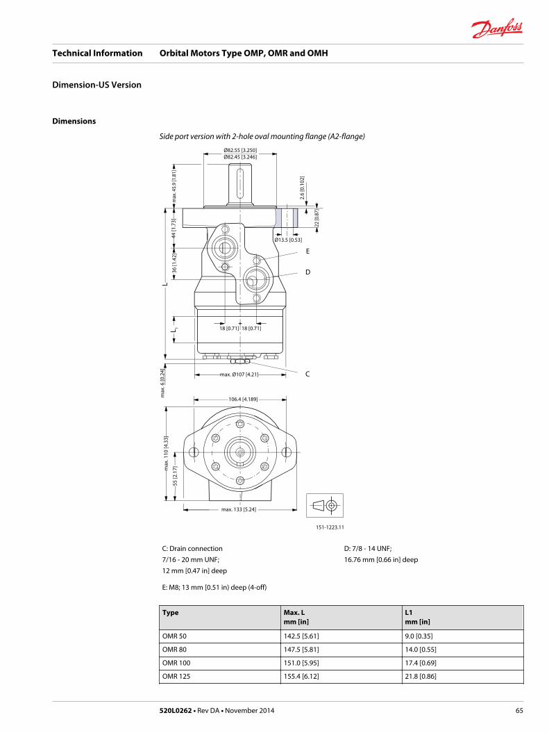
Dimensions
Side port version with 2-hole oval mounting flange (A2-flange)
Ø82.55 [3.250]Ø82.45 [3.246]
Ø13.5 [0.53]
18 [0.71] 18 [0.71]
max. Ø107 [4.21]
106.4 [4.189]
max. 133 [5.24]
151-1223.11
max
. 6 [0
.24]
36 [1
.42]
max
. 45.
9 [1
.81]
44 [1
.73]
2.6
[0.1
02]
22 [0
.87]
LL 1
max
. 110
[4.3
3]
55 [2
.17]
C
D
E
C: Drain connection7/16 - 20 mm UNF;12 mm [0.47 in] deep
D: 7/8 - 14 UNF;16.76 mm [0.66 in] deep
E: M8; 13 mm [0.51 in) deep (4-off)
Type Max. Lmm [in]
L1mm [in]
OMR 50 142.5 [5.61] 9.0 [0.35]
OMR 80 147.5 [5.81] 14.0 [0.55]
OMR 100 151.0 [5.95] 17.4 [0.69]
OMR 125 155.4 [6.12] 21.8 [0.86]
Technical Information Orbital Motors Type OMP, OMR and OMH
Dimension-US Version
520L0262 • Rev DA • November 2014 65
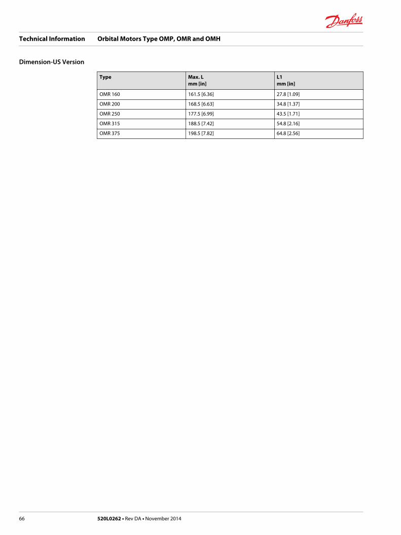
Type Max. Lmm [in]
L1mm [in]
OMR 160 161.5 [6.36] 27.8 [1.09]
OMR 200 168.5 [6.63] 34.8 [1.37]
OMR 250 177.5 [6.99] 43.5 [1.71]
OMR 315 188.5 [7.42] 54.8 [2.16]
OMR 375 198.5 [7.82] 64.8 [2.56]
Technical Information Orbital Motors Type OMP, OMR and OMH
Dimension-US Version
66 520L0262 • Rev DA • November 2014

Dimensions
Side port version with 4-hole oval mounting flange (A4 flange)
Ø82.55 [3.250]Ø82.45 [3.246]
Ø13.5 [0.53]
18 [0.71]18 [0.71]
max. Ø107 [4.21]
106.4 [4.189]
max. 133 [5.24]
151-1751.11
16 [0
.63]
8 [0
.31]
45˚
36 [1
.42]
38 [1
.50]
max
. 6 [0
.24]
55 [2
.17]
max
. 110
[4.3
3]
E
C
LL 1
L 2
D
C: Drain connectionG ¼; 15 mm [0.47 in] deep
D: G ½; 15 mm [0.59 in] deep
E: M8; 13 mm [0.51 in] deep(4 pcs.)
Output shaft.max. L2mm [in]
Cylindrical shaft 32 mm [1.26 in] 68.3 [2.69]
Cylindrical shaft 25 mm [0.98 in] 55.3 [2.18]
Tapered shaft 28.56 mm [1.12 in] 56.3 [2.19]
Technical Information Orbital Motors Type OMP, OMR and OMH
Dimensions-European Version
520L0262 • Rev DA • November 2014 67

Type Max. Lmm [in]
L1mm [in]
OMR 50 136.5 [5.37] 9.0 [0.35]
OMR 80 141.5 [5.57] 14.0 [0.55]
OMR 100 145.0 [5.71] 17.4 [0.69]
OMR 125 149.5 [5.89] 21.8 [0.86]
OMR 160 155.5[6.12] 27.8 [1.09]
OMR 200 162.5 [6.40] 34.8 [1.37]
OMR 250 171.5 [6.75] 43.5 [1.71]
OMR 315 182.5[7.19] 54.8 [2.16]
OMR 375 192.7 [7.59] 65.0 [2.56]
Technical Information Orbital Motors Type OMP, OMR and OMH
Dimensions-European Version
68 520L0262 • Rev DA • November 2014

Dimensions
Side port version with 4-hole oval mounting flange (A4-flange)
Ø82.55 [3.250]Ø82.45 [3.246]
Ø13.5 [0.53]
18 [0.71]18 [0.71]
max. Ø107 [4.21]
106.4 [4.189]
max. 133 [5.24]
151-1221.11
16 [0
.63]
8 [0
.31]
38 [1
.50]
36 [1
.42]
max
. 58.
2 [2
.291
]m
ax. 6
[0.2
4]55
[2.1
7]
45º
max
. 110
[4.3
3]
E
C
LL 1
D
C: Drain connection7/16 - 20 UNF;12 mm [0.47 in] deep
D: 7/8 - 14 UNF;17 mm [0.66 in] deep
E: M8; 13 mm [0.51 in) deep (4-off)
Type Max. Lmm [in]
L1mm [in]
OMR 50 136.5 [5.37] 9.0 [0.35]
OMR 80 141.5 [5.57] 14.0 [0.55]
OMR 100 145.0 [5.71] 17.4 [0.69]
Technical Information Orbital Motors Type OMP, OMR and OMH
Dimensions-US Version
520L0262 • Rev DA • November 2014 69

Type Max. Lmm [in]
L1mm [in]
OMR 125 149.5 [5.89] 21.8 [0.86]
OMR 160 155.5 [6.12] 27.8 [1.09]
OMR 200 162.5 6.40] 34.8 [1.37]
OMR 250 171.5 [6.75] 43.5 [1.71]
OMR 315 182.5 [7.19] 54.8 [2.16]
OMR 375 192.7 [7.59] 65.0 [2.56]
Technical Information Orbital Motors Type OMP, OMR and OMH
Dimensions-US Version
70 520L0262 • Rev DA • November 2014

Dimensions
End port version with square mounting flange (C-flange)
Ø44.45 [1.750]Ø44.35 [1.746]
18 [0.71] 18 [0.71]
31.2 [1.283]25 [0.98]
max. Ø107 [4.21]
Ø82.55
[3.25
0]
max. 84 [3.31]
R15 [0.59]
151-1753.11
2.5
[0.0
.98]
7.1
[0.2
80]
20 [0
.79]
max
. 113
[4.4
5]
5 [0
.20]
max
. 8.7
[0.3
43]
55 [2
.17]
max
. 84
[3.3
1]
max
. 49.
5 [1
.949
]
C
E
LL 1
D
C: Drain connectionG ¼; 12 mm [0.47 in] deep
D: G ½; 15 mm [0.59 in] deep E: M10; 15 mm [0.59 in] deep(4 pcs.)
Technical Information Orbital Motors Type OMP, OMR and OMH
Dimensions-European Version
520L0262 • Rev DA • November 2014 71

Type Max. Lmm [in]
L1mm [in]
OMR 50 157.6 [6.21] 9.0 [0.35]
OMR 80 162.6 [6.40] 14.0 [0.55]
OMR 100 166.0 [6.54] 17.4 [0.69]
OMR 125 170.4 [6.71] 21.8 [0.86]
OMR 160 176.4 [6.95] 27.8 [1.09]
OMR 200 183.4 [7.22] 34.8 [1.37]
OMR 250 192.1 [7.56] 43.5 [1.71]
OMR 315 203.4 [8.02] 54.8 [2.16]
OMR 375 213.5 [8.41] 65.0 [2.56]
Technical Information Orbital Motors Type OMP, OMR and OMH
Dimensions-European Version
72 520L0262 • Rev DA • November 2014

Dimensions
Side port version with square mounting flange (C-flange)
E
D
C
F
151-1220.11
max. 84 [3.31]
R15 [0.59]
max. Ø107 [4.21]
18 [0.71] 18 [0.71]
Ø44.45 [1.750]Ø44.35 [1.746]
2.5
[0.0
98]
max
. 6 [0
.24]
max
. 84
[3.3
1]
55 [2
.17]m
ax. 1
10 [4
.33]
44 [1
.73]
36 [1
.42]
max
. 46.
3 [1
.823
]
ø82.5
5 [3.2
50]
LL 1
C: Drain connection7/16 - 20 mm UNF;12 mm [0.47 in] deep
D: 7/8 - 14 UNF;17 mm [0.66 in] deep
E: M8; 13 mm [0.51 in) deep (4-off) F: 3/8 - 16 UNC;15 mm [0.59 in] deep (4-off)
Type Max. Lmm [in]
L1mm [in]
OMR 50 142.5 [5.61] 9.0 [0.35]
OMR 80 147.5 [5.81] 14.0 [0.55]
OMR 100 151.0 [5.95] 17.4 [0.69]
OMR 125 155.4 [6.12] 21.8 [0.86]
Technical Information Orbital Motors Type OMP, OMR and OMH
Dimensions-US Version
520L0262 • Rev DA • November 2014 73

Type Max. Lmm [in]
L1mm [in]
OMR 160 161.5 [6.36] 27.8 [1.09]
OMR 200 168.5 [6.63] 34.8 [1.37]
OMR 250 177.5 [6.99] 43.5 [1.71]
OMR 315 188.5 [7.42] 54.8 [2.16]
OMR 375 198.7 [7.82] 65.0 [2.56]
Technical Information Orbital Motors Type OMP, OMR and OMH
Dimensions-US Version
74 520L0262 • Rev DA • November 2014
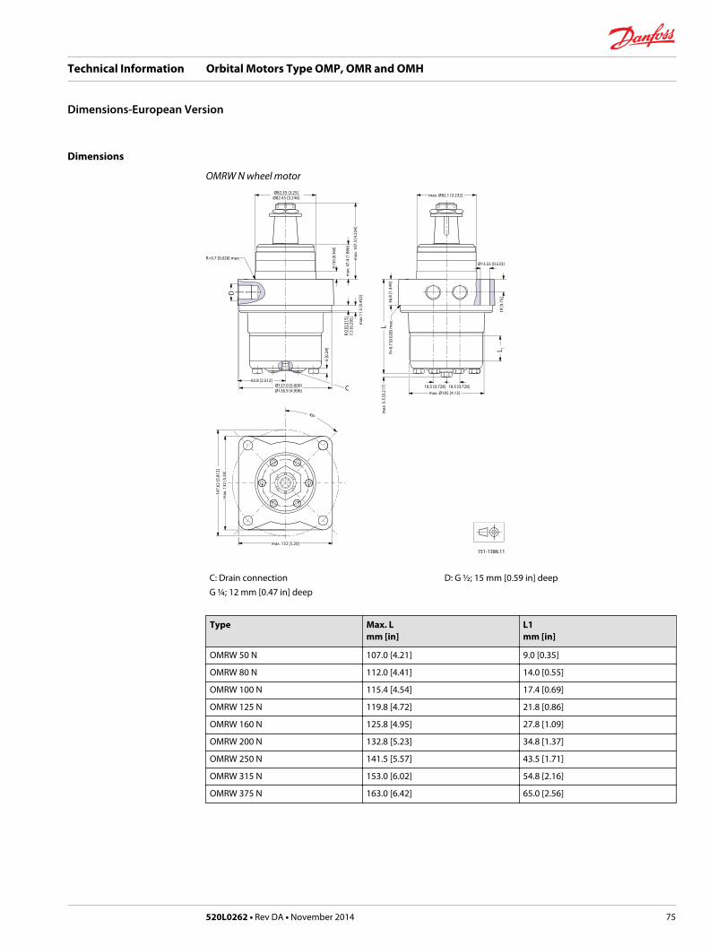
Dimensions
OMRW N wheel motor
max. Ø82.1 [3.232]Ø82.55 [3.25]Ø82.45 [3.246]
Ø13.55 [0.533]R=0.7 [0.028] max.
18.5 [0.728] 18.5 [0.728]max. Ø105 [4.13]
147.
62 [5
.812
]
151-1386.11
19 [0
.75]
max
. 107
.3 [4
.224
]
8.0
[0.3
15]
7.5
[0.2
95]
36.8
[1.4
49]
9.15
0 [0
.360
]
63.8 [2.512]Ø127.0 [5.000]Ø126.9 [4.996]
max. 132 [5.20]
45º
max
. 132
[5.2
0]
6 [0
.24]
R=0.
7 [0
.028
] max
.
max
. 5.5
[0.2
17]
CL
L 1
D
max
11.
5 [0
.453
]
max
. 47.
4 [1
.866
]
C: Drain connectionG ¼; 12 mm [0.47 in] deep
D: G ½; 15 mm [0.59 in] deep
Type Max. Lmm [in]
L1mm [in]
OMRW 50 N 107.0 [4.21] 9.0 [0.35]
OMRW 80 N 112.0 [4.41] 14.0 [0.55]
OMRW 100 N 115.4 [4.54] 17.4 [0.69]
OMRW 125 N 119.8 [4.72] 21.8 [0.86]
OMRW 160 N 125.8 [4.95] 27.8 [1.09]
OMRW 200 N 132.8 [5.23] 34.8 [1.37]
OMRW 250 N 141.5 [5.57] 43.5 [1.71]
OMRW 315 N 153.0 [6.02] 54.8 [2.16]
OMRW 375 N 163.0 [6.42] 65.0 [2.56]
Technical Information Orbital Motors Type OMP, OMR and OMH
Dimensions-European Version
520L0262 • Rev DA • November 2014 75

Dimensions
OMRW N wheel motorØ82.55 [3.25]
Ø82.45 [3.246]
Ø13.55 [0.533]
18.5 [0.728] 18.5 [0.728]
147.
62 [5
.812
]
151-1625.11
19 [0
.75]
max
. 107
.3 [4
.224
]
10.5
[0.4
139.
5 [0
.374
]
36.8
[1.4
49]
9.15
0 [0
.360
]
55 [2.17]
Ø127.0 [5.000]Ø126.9 [4.996]
max. 132 [5.20]
45º
max
. 132
[5.2
0]
3.0
[0.1
18] x
45º
R=0.
6 [0
.24]
max
. 5.5
[0.2
17]C
L
L 1
D
R0.6
[0.0
24]
max
. 47.
4 [1
.866
]
C: Drain connection7/16 - 20 UNF;12 mm [0.47 in] deep
D: 7/8 - 14 UNF;17 mm [0.66 in] deep
Type Max. Lmm [in]
L1mm [in]
OMRW 50 N 107.0 [4.21] 9.0 [0.35]
OMRW 80 N 112.0 [4.41] 14.0 [0.55]
OMRW 100 N 115.4 [4.54] 17.4 [0.69]
OMRW 125 N 119.8 [4.72] 21.8 [0.86]
OMRW 160 N 125.8 [4.95] 27.8 [1.09]
OMRW 200 N 132.8 [5.23] 34.8[1.37]
OMRW 250 N 141.5 [5.57] 43.5 [1.71]
OMRW 315 N 153.0 [6.02] 54.8 [2.16]
OMRW 375 N 163.0 [6.42] 65.0 [2.56]
Technical Information Orbital Motors Type OMP, OMR and OMH
Dimensions-US Version
76 520L0262 • Rev DA • November 2014

Dimensions
OMR F motor
151-1719.11
Ø82.55 [3.25]Ø82.45 [3.246]
Ø13.55 [0.533]
Ø102 [4.02] 25.715º 25.715º
max Ø107 [4.21]
106.4 [4.189]
36 [1
.42]
38 [1
.50]
max
. 55.
3 [2
.177
]
8 [0
.31]
16 [0
.63]
18 [0.71] 18 [0.71]
max. 133 [5.24]
55 [2
.17]
max
. 110
[4.3
3]
E
B
BB
B
FC
B-B
C
D
F
L
L 1
L 2
L 3
C: Drain connectionG ¼; 12 mm [0.47 in] deep
D: G ½; 15 mm [0.59 in] deep
E: M8; 13 mm [0.51 in] deep F: Brake release connection G ¼
Type Max. Lmm [in]
L1mm [in]
L2mm [in]
L3mm [in]
OMR 80 F 241.3 [9.50] 14.0 [0.55] 187.3 [7.37] 210.8 [8.30]
OMR 100 F 244.7[9.63] 17.4 [0.69] 190.7 [7.51] 214.2 [8.43]
OMR 125 F 249.1 [9.81] 21.8 [0.86] 195.1 [7.68] 218.6 [8.61]
OMR 160 F 255.1 [10.04] 27.8 [1.09] 201.1 [7.92] 224.6 [8.84]
OMR 200 F 262.1 [10.32] 34.8 [1.37] 208.1 [8.19] 231.6 [9.12]
OMR 250 F 270.8 [10.66] 43.5 [1.71] 216.8 [8.54] 240.3 [9.46]
OMR 315 F 282.1 [11.11] 54.8 [2.16] 228.1 [8.98] 251.6 [9.91]
OMR 375 F 292.3 [11.51] 65.0 [2.56] 238.3 [9.38] 261.8 [10.31]
Technical Information Orbital Motors Type OMP, OMR and OMH
Dimensions-European Version
520L0262 • Rev DA • November 2014 77

Dimensions
OMR NF motor
151-1719.11
Ø82.55 [3.25]Ø82.45 [3.246]
Ø13.55 [0.533]
Ø102 [4.02] 25.715º 25.715º
max Ø107 [4.21]
106.4 [4.189]
36 [1
.42]
38 [1
.50]
max
. 55.
3 [2
.177
]
8 [0
.31]
16 [0
.63]
18 [0.71] 18 [0.71]
max. 133 [5.24]
55 [2
.17]
max
. 110
[4.3
3]
E
B
BB
B
FC
B-B
C
D
F
L
L 1
L 2
L 3
C: Drain connection7/16 - 20 UNF
D: 7/8 -14 UNF, 0.66 in (15 mm) deep
E: M8; 0.51 in (13 mm ) deep F: Brake release connection 7/16 - 20 UNF
Type Max. Lmm [in]
L1mm [in]
L2mm [in]
L3mm [in]
OMR 80 NF 247.3 [9.74] 14.0 [0.55] 193.3 [7.61] 216.8 [8.54]
OMR 100 NF 250.7 [9.87] 17.4 [0.69] 196.7 [7.74] 220.2 [8.67]
OMR 125 NF 255.1 [10.04] 21.8 [0.86] 201.1 [7.92] 224.6 [8.84]
OMR 160 NF 261.1 [10.28] 27.8 [1.09] 207.1 [8.15] 230.6 [9.08]
OMR 200 NF 268.1 [10.55] 34.8 [1.37] 214.1 [8.43] 237.6 [9.35]
OMR 250 NF 276.8 [10.90] 43.5 [1.71] 222.8 [8.77] 246.3 [9.70]
OMR 315 NF 288.1 [11.34] 54.8 [2.16] 234.1 [9.22] 257.6[10.14]
OMR 375 NF 298.3 [11.74] 65.0 [2.56] 244.3 [9.62] 267.8 [10.54]
Technical Information Orbital Motors Type OMP, OMR and OMH
Dimensions-US Version
78 520L0262 • Rev DA • November 2014
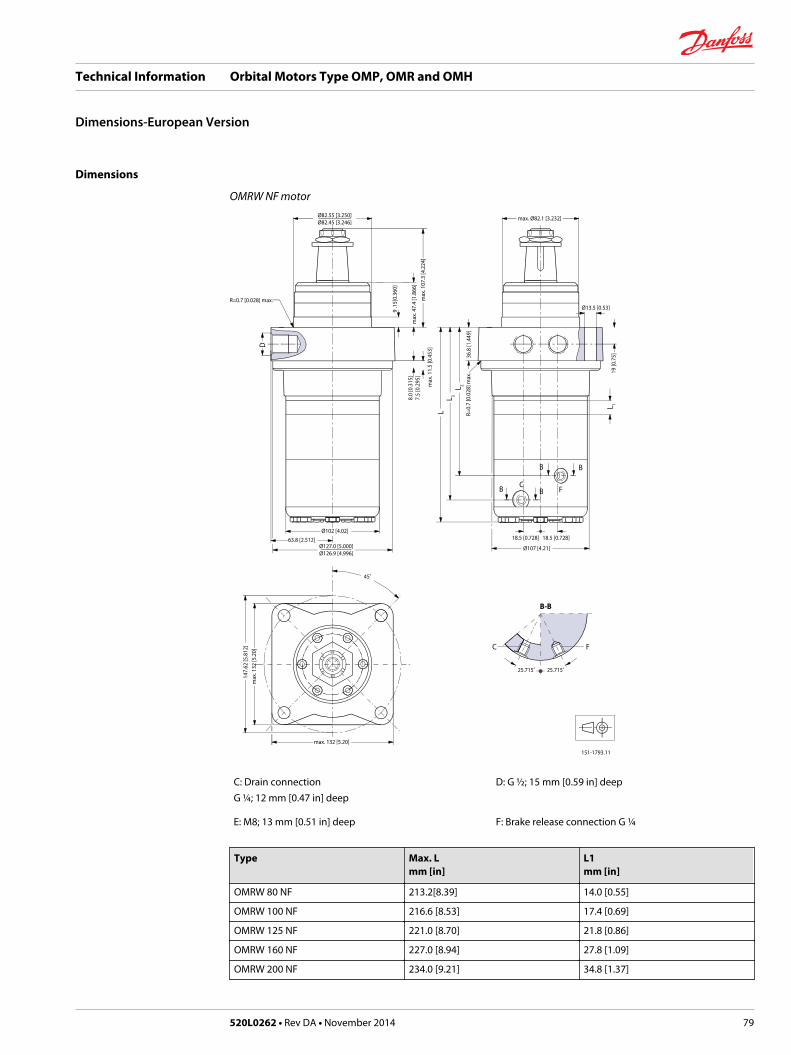
Dimensions
OMRW NF motorØ82.55 [3.250]Ø82.45 [3.246]
Ø13.5 [0.53]
18.5 [0.728]18.5 [0.728]
Ø107 [4.21]
max. Ø82.1 [3.232]
Ø127.0 [5.000]Ø126.9 [4.996]
63.8 [2.512]Ø102 [4.02]
max. 132 [5.20]
25.715˚ 25.715˚
151-1793.11
19 [0
.75]
8.0
[0.3
15]
7.5
[0.2
95]
45˚
147.
62 [5
.812
]m
ax. 1
32 [5
.20]
9 .1
5[0.
360]
max
. 47.
4 [1
.866
]m
ax. 1
07.3
[4.2
24]
R=0.
7 [0
.028
] max
.
R=0.7 [0.028] max.
max
. 11.
5 [0
.453
]
36.8
[1.4
49]
C
B-B
F
CF
B
B B
B
L
L 1
L 3L 2
D
C: Drain connectionG ¼; 12 mm [0.47 in] deep
D: G ½; 15 mm [0.59 in] deep
E: M8; 13 mm [0.51 in] deep F: Brake release connection G ¼
Type Max. Lmm [in]
L1mm [in]
OMRW 80 NF 213.2[8.39] 14.0 [0.55]
OMRW 100 NF 216.6 [8.53] 17.4 [0.69]
OMRW 125 NF 221.0 [8.70] 21.8 [0.86]
OMRW 160 NF 227.0 [8.94] 27.8 [1.09]
OMRW 200 NF 234.0 [9.21] 34.8 [1.37]
Technical Information Orbital Motors Type OMP, OMR and OMH
Dimensions-European Version
520L0262 • Rev DA • November 2014 79

Type Max. Lmm [in]
L1mm [in]
OMRW 250 NF 242.7 [9.56] 43.5 [1.71]
OMRW 315 NF 254.0 [10.0] 54.8 [2.16]
OMRW 375 NF 264.2 [10.40] 65.0 [2.56]
Type Max. L2mm [in]
L3mm [in]
OMRW 80 NF 159.2 [6.27] 182.7 [7.19]
OMRW 100 NF 162.6 [6.40] 186.1 [7.50]
OMRW 125 NF 167.0 [6.57] 190.5 [7.50]
OMRW 160 NF 173.0 [6.81] 196.5 [7.74]
OMRW 200 NF 180.0 [7.09] 203.5 [8.01]
OMRW 250 NF 188.7[7.43] 212.2 [8.35]
OMRW 315 NF 200.0 [7.87] 223.5 [8.80]
OMRW 375 NF 210.2 [8.28] 233.7 [9.20]
Technical Information Orbital Motors Type OMP, OMR and OMH
Dimensions-European Version
80 520L0262 • Rev DA • November 2014

Versions
Mounting flange Spigotdiameter(front /rearend)
Bolt circlediameter(BC)
Shaft Portsize
EU US Sideport
Endport
Flange port
Std.shaftseal
Highpressureshaftseal
Drainconnection
Checkvalve
Maintypedesignation
4 hole oval flange(A4-flange)
∅ 82.5 mm[3.25 in]
∅ 106.4 mm[4.20 in]
Cyl. 32 mm G ½ * * * Yes Yes OMH
Cyl. 35 mm G ½ * * * Yes Yes OMH
Cyl. 11/4 in 7/8 - 14UNF
* * * Yes Yes OMH
Splined 1inSAE 6B
7/8 - 14UNF
* * * Yes Yes OMH
Splined11/4 in
G ½ * * * Yes Yes OMH
Splined11/4 in
7/8 - 14UNF
* * * Yes Yes OMH
Tapered 35mm
G ½ * * * Yes Yes OMH
* Version is available.
Technical Information Orbital Motors Type OMP, OMR and OMH
Version
520L0262 • Rev DA • November 2014 81
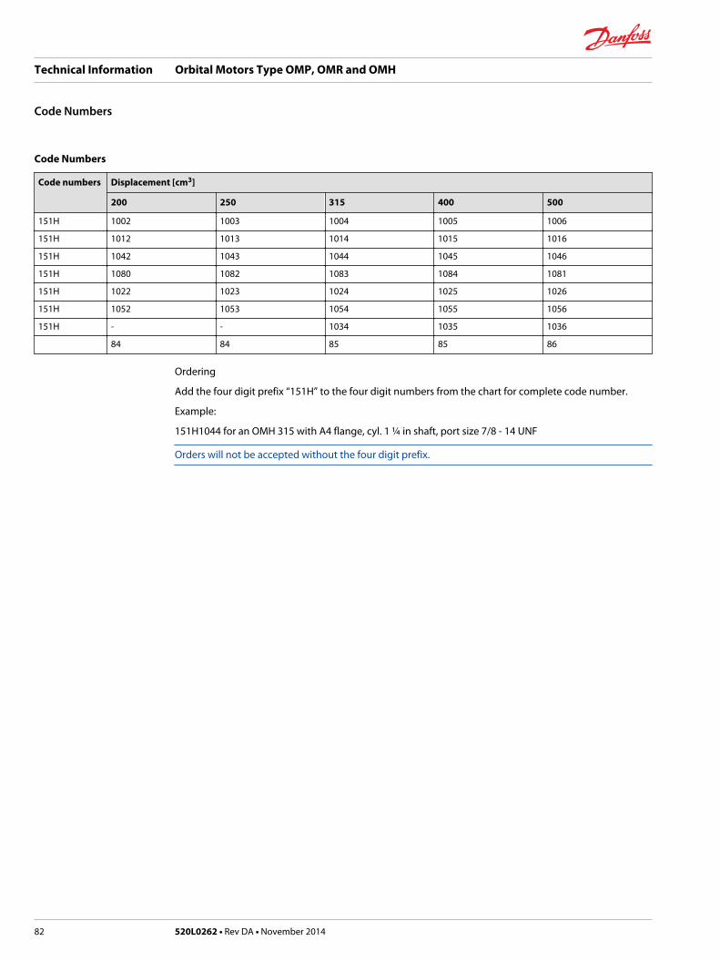
Code Numbers
Code numbers Displacement [cm3]
200 250 315 400 500
151H 1002 1003 1004 1005 1006
151H 1012 1013 1014 1015 1016
151H 1042 1043 1044 1045 1046
151H 1080 1082 1083 1084 1081
151H 1022 1023 1024 1025 1026
151H 1052 1053 1054 1055 1056
151H - - 1034 1035 1036
84 84 85 85 86
Ordering
Add the four digit prefix “151H” to the four digit numbers from the chart for complete code number.
Example:
151H1044 for an OMH 315 with A4 flange, cyl. 1 ¼ in shaft, port size 7/8 - 14 UNF
Orders will not be accepted without the four digit prefix.
Technical Information Orbital Motors Type OMP, OMR and OMH
Code Numbers
82 520L0262 • Rev DA • November 2014

Technical data for OMH with 1 in SAE 6 B splined shaft
Type OMH OMH OMH OMH OMH
Motor size 200 250 315 400 500
Geometric displacement cm3
[inch]201.3[12.32]
252.0[15.42]
314.9[19.27]
396.8[24.28]
470.6[28.80]
Max. speed min-1 cont. 370 295 235 185 155
[rpm] int.1) 445 350 285 225 190
Max. torque N•m[lbf•in]
cont. 340[3000]
340[3000]
340[3000]
340[3000]
340[3000]
int.1) 510[4500]
510[4500]
540[4800]
540[4800]
520[4600]
peak2) 610[5400]
610[5400]
610[5400]
610[5400]
610[5400]
Max. output kW[hp]
cont. 11.2[15.0]
7.5[10.0]
5.2[7.0]
4.8[6.5]
3.7[5.0]
int.1) 17.2[23.0]
11.9[16.0]
9.7[13.0]
8.2[11.0]
6.0[8.0]
Max. pressure drop bar[psi]
cont. 115[1650]
90[1300]
75[1100]
60[900]
50[725]
int.1) 170[2500]
145[2100]
120[1750]
95[1400]
75[1100]
peak2) 215[3120]
175[2540]
145[2100]
110[1600]
90[1300]
Max. oil flow l/min[US gal/min]
cont. 75[19.8]
75[19.8]
75[19.8]
75[19.8]
75[19.8]
int.1) 90[23.8]
90[23.8]
90[23.8]
90[23.8]
90[23.8]
Max. starting pressure withunloaded shaft
bar[psi]
7[100]
7[100]
7[100]
7[100]
7[100]
Min starting torque at max. press drop cont.N•m [lbf•in]
255[2250]
270[2400]
280[2500]
290[2550]
300[2650]
at max. press.drop int.1)
N•m [lbf•in]390[3450]
435[3850]
450[4000]
450[4000]
450[4000]
1) Intermittent operation: the permissible values may occur for max. 10% of every minute.2) Peak load: the permissible values may occur for max. 1% of every minute.
Technical data for OMH with 32 mm and 1 1/4 in cylindrical shaft
Type OMH OMH OMH OMH OMH
Motor size 200 250 315 400 500
Geometric displacement cm3
[inch]201.3[12.32]
252.0[15.42]
314.9[19.27]
396.8[24.28]
470.6[28.80]
Max. speed min-1 cont. 370 295 235 185 155
[rpm] int.1) 445 350 285 225 190
Technical Information Orbital Motors Type OMP, OMR and OMH
Technical Data
520L0262 • Rev DA • November 2014 83

Type OMH OMH OMH OMH OMH
Motor size 200 250 315 400 500
Max. torque N•m[lbf•in]
cont. 510[4500]
610[5400}
590[5220]
590[5220]
580[5130]
int.1) 580[5130]
700[6200]
670[5930]
700[6200]
680[6020]
peak2) 640[5660]
790[6990]
840[7440]
840[7440]
840[7440]
Max. output kW[hp]
cont. 16.0[21.5]
16.0[21.5]
12.5[16.8]
10.0[13.4]
8.5[11.4]
int.1) 18.5[24.8]
18.5[24.8]
14.0[18.8]
12.0[16.1]
10.0[13.4]
Max. pressure drop bar[psi]
cont. 175[2540]
175[2540]
135[1960]
105[1520]
85[1230]
int.1) 200[2900]
200[2900]
155[2250]
125[1810]
100[1450]
peak2) 225[3260]
225[3260]
190[2760]
155[2250]
130[1890]
Max. oil flow l/min[US gal/min]
cont. 75[19.8]
75[19.8]
75[19.8]
75[19.8]
75[19.8]
int.1) 90[23.8]
90[23.8]
90[23.8]
90[23.8]
90[23.8]
Max. starting pressure withunloaded shaft
bar[psi]
7[100]
7[100]
7[100]
7[100]
7[100]
Min starting torque at max. press drop cont.N•m [lbf•in]
390[3450]
520[4600]
510[4510]
490[4340]
490[4340]
at max. press.drop int.1)
N•m [lbf•in]450[3980]
590[5220]
590[5220]
600[5310]
600[5310]
1) Intermittent operation: the permissible values may occur for max. 10% of every minute.2) Peak load: the permissible values may occur for max. 1% of every minute.
Technical data for OMH with 35 mm cylindrical, 1 1/4 in splined and 35 mm tapered shaft
Type OMH OMH OMH OMH OMH
Motor size 200 250 315 400 500
Geometric displacement cm3
[inch]201.3[12.32]
252.0[15.42]
314.9[19.27]
396.8[24.28]
470.6[28.80]
Max. speed min-1 cont. 370 295 235 185 155
[rpm] int.fn 445 350 285 225 190
Max. torque N•m[lbf•in]
cont. 510[4500]
610[5400}
740[6550]
840[7440]
820[7260]
int.fn 580[5130]
700[6200]
820[7260]
980[8670]
1040[9210]
peak2) 640[5660]
790[6990]
980[8670]
1090[9650]
1170[10360]
Max. output kW[hp]
cont. 16.0[21.5]
16.0[21.5]
14.0[18.8]
12.5[16.8]
11.0[14.8]
int.fn 18.5[24.8]
18.5[24.8]
15.5[20.8
15.0[20.1]
14.0[18.8]
Technical Information Orbital Motors Type OMP, OMR and OMH
Technical Data
84 520L0262 • Rev DA • November 2014
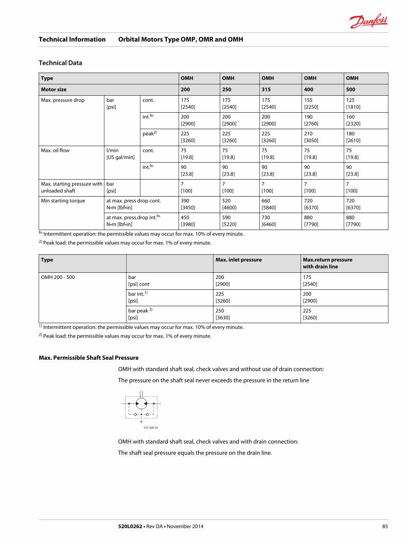
Type OMH OMH OMH OMH OMH
Motor size 200 250 315 400 500
Max. pressure drop bar[psi]
cont. 175[2540]
175[2540]
175[2540]
155[2250]
125[1810]
int.fn 200[2900]
200[2900]
200[2900]
190[2760]
160[2320]
peak2) 225[3260]
225[3260]
225[3260]
210[3050]
180[2610]
Max. oil flow l/min[US gal/min]
cont. 75[19.8]
75[19.8]
75[19.8]
75[19.8]
75[19.8]
int.fn 90[23.8]
90[23.8]
90[23.8]
90[23.8]
90[23.8]
Max. starting pressure withunloaded shaft
bar[psi]
7[100]
7[100]
7[100]
7[100]
7[100]
Min starting torque at max. press drop cont.N•m [lbf•in]
390[3450]
520[4600]
660[5840]
720[6370]
720[6370]
at max. press.drop int.fn
N•m [lbf•in]450[3980]
590[5220]
730[6460]
880[7790]
880[7790]
fn Intermittent operation: the permissible values may occur for max. 10% of every minute.2) Peak load: the permissible values may occur for max. 1% of every minute.
Type Max. inlet pressure Max.return pressurewith drain line
OMH 200 - 500 bar[psi] cont
200[2900]
175[2540]
bar int.1)
[psi]225[3260]
200[2900]
bar peak 2)
[psi]250[3630]
225[3260]
1) Intermittent operation: the permissible values may occur for max. 10% of every minute.2) Peak load: the permissible values may occur for max. 1% of every minute.
Max. Permissible Shaft Seal Pressure
OMH with standard shaft seal, check valves and without use of drain connection:
The pressure on the shaft seal never exceeds the pressure in the return line
151-320.10
OMH with standard shaft seal, check valves and with drain connection:
The shaft seal pressure equals the pressure on the drain line.
Technical Information Orbital Motors Type OMP, OMR and OMH
Technical Data
520L0262 • Rev DA • November 2014 85

Max. return pressure without drain line or max. pressure in the drain line
psi
1400
1200
1000
800
600
400
200
0
bar100
75
50
25
0
int.operation 1)
151-1565.10
min-1
(rpm)0 100 200 300 400
1) Intermittent operation: the permissible values may occur for max. 10% of every minute.
Pressure Drop in Motor
The curve applies to an unloaded motor shaft and an oil viscosity of 35 mm2/s [165 SUS]
psi
250
200
150
100
50
0
bar18
16
14
12
10
8
6
4
2
00 10 20 30 40 50 60 70 80 90 l/min
0 2 4 6 8 10 12 14 16 18 20 22 24 US gal/min
151-1331.10
Q
Q
∆ p∆ p
Oil Flow in Drain Line
The table shows the max. oil flow in the drain line at a return pressure less than 5-10 bar [75-150 psi].
Pressure drop bar[psi]
Viscosity Oil flow in drain line
mm2/s [SUS] l/min [US gal/min]
100[1450]
20 [100] 2.5 [0.66]
35 [165] 1.8 [0.78]
140[2030]
20 [100] 3.5 [0.93]
35 [165] 2.8 [0.74]
Technical Information Orbital Motors Type OMP, OMR and OMH
Technical Data
86 520L0262 • Rev DA • November 2014

Direction of Shaft Rotation
151-2107.10
Permissible Shaft Loads for OMH
The permissible shaft load (Prad) is calculated from the speed (n) and the distance (l) between the pointof load application and the mounting flange.
*n > 200 min-1 (rpm); l < 60 mm [2.36 in]
n < 200 min-1 (rpm); => PRmax = 11000 N [2475 lbf]
------ 1 in SAE 6B splined shaft
3000
2500
2000
1500
1000
500
0
12000
10000
8000
6000
4000
2000
00 100 200 300 400
675 lbf3000 N
3000 N675 lbf
151-1474.10
30 [1.18]
Prad.
Prad.Prad.lbf N
The drawing shows the permissible radial load when l = 30 mm [1.18 in].
Technical Information Orbital Motors Type OMP, OMR and OMH
Technical Data
520L0262 • Rev DA • November 2014 87
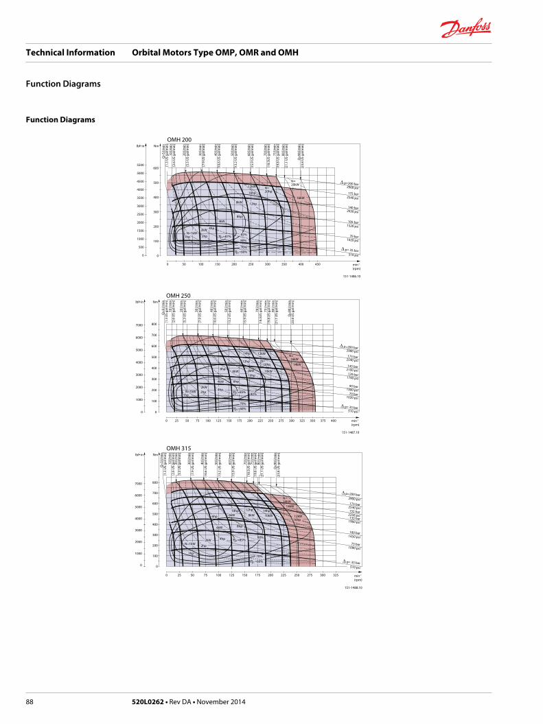
Function Diagrams
OMH 200lbf• in Nm
5500
5000
4500
4000
3500
3000
2500
2000
1500
1000
500
0
600
500
400
300
200
100
0
0 50 100 150 200 250 300 350 400 450
151-1486.10
min-1
(rpm)
Q=5
l/m
in[1
.3 U
S ga
l/min
]10
l/m
in[2
.6 U
S ga
l/min
]
20 l/
min
[5.3
US
gal/m
in]
30 l/
min
[7.9
US
gal/m
in]
40 l/
min
[10.
6 U
S ga
l/min
]
50 l/
min
[13.
2 U
S ga
l/min
]
60 l/
min
[15.
9 U
S ga
l/min
]
70 l/
min
[18.
5US
gal/m
in]
75 l/
min
[19.
8 U
S ga
l/min
]80
l/m
in[2
1.1
US
gal/m
in]
Q=9
0 l/m
in[2
3.8
US
gal/m
in]
175 bar
∆ p= 35 bar
1520 psi
2030 psi
2540 psi
∆ p=200 bar2900 psi
510 psi
1020 psi70 bar
105 bar
140 bar
N=1kW
4kW
16kW
12kW
N=20kW
8kW
85%
80%
8hp
12hp
16hpN=20hp
η t =87%
η t =60%70%
1hp
4hp2kW
2hp
OMH 250lbf• in Nm
7000
6000
5000
4000
3000
2000
1000
0
800
700
600
500
400
300
200
100
0
151-1487.10
min-1
(rpm)
Q=5
l/m
in[1
.3 U
S ga
l/min
]10
l/m
in[2
.6 U
S ga
l/min
]
20 l/
min
[5.3
US
gal/m
in]
30 l/
min
[7.9
US
gal/m
in]
40 l/
min
[10.
6 U
S ga
l/min
]
50 l/
min
[13.
2 U
S ga
l/min
]
60 l/
min
[15.
9 U
S ga
l/min
]
70 l/
min
[18.
5US
gal/m
in]
75 l/
min
[19.
8 U
S ga
l/min
]80
l/m
in[2
1.1
US
gal/m
in]
Q=9
0 l/m
in[2
3.8
US
gal/m
in]
175 bar
∆ p= 35 bar
1300 psi
2100 psi
2540 psi
∆ p=200 bar2900 psi
510 psi
1020 psi70 bar
90 bar
1740 psi120 bar
145 bar
N=1kW
4kW
10kW
14kW
12kW
6kW
N= 16kW
8kW
80%
8hp
12hp
14hp
6hp
10hp
N= 16hp
η t =85%
η t =60%70%
1hp
4hp2kW2hp
0 25 50 75 100 125 150 175 200 225 250 275 300 325 350 375 400
OMH 315lbf• in Nm
7000
6000
5000
4000
3000
2000
1000
0
800
700
600
500
400
300
200
100
0
0 25 50 75 100 125 150 175 200 225 250 275 300 325
151-1488.10
min-1
(rpm)
Q=5
l/m
in[1
.3 U
S ga
l/min
]10
l/m
in[2
.6 U
S ga
l/min
]20
l/m
in[5
.3 U
S ga
l/min
]
30 l/
min
[7.9
US
gal/m
in]
40 l/
min
[10.
6 U
S ga
l/min
]
50 l/
min
[13.
2 U
S ga
l/min
]
60 l/
min
[15.
9 U
S ga
l/min
]
70 l/
min
[18.
5US
gal/m
in]
75 l/
min
[19.
8 U
S ga
l/min
]80
l/m
in[2
1.1
US
gal/m
in]
Q=9
0 l/m
in[2
3.8
US
gal/m
in]
175 bar
∆ p= 35 bar
1450 psi
1960 psi
2540 psi
∆ p=200 bar2900 psi
510 psi
1090 psi75 bar
100 bar
135 bar2250 psi155 bar
N=1kW
4kW
14kW
10kW6kW 12kW
N=16kW
8kW
80%
8hp
12hp
6hp
10hp 14hp
16hp
η t =85%
η t =60%
70%1hp
4hp2kW
2hp
Technical Information Orbital Motors Type OMP, OMR and OMH
Function Diagrams
88 520L0262 • Rev DA • November 2014

OMH 400lbf• in Nm
9000
8000
7000
6000
5000
4000
3000
2000
1000
0
1000
800
600
400
200
0
0 25 50 75 100 125 150 175 200 225 250 275
151-1489.10
min-1
(rpm)
Q=5
l/m
in[1
.3 U
S ga
l/min
]10
l/m
in[2
.6 U
S ga
l/min
]
20 l/
min
[5.3
US
gal/m
in]
30 l/
min
[7.9
US
gal/m
in]
40 l/
min
[10.
6 U
S ga
l/min
]
50 l/
min
[13.
2 U
S ga
l/min
]
60 l/
min
[15.
9 U
S ga
l/min
]
70 l/
min
[18.
5US
gal/m
in]
75 l/
min
[19.
8 U
S ga
l/min
]
80 l/
min
[21.
1 U
S ga
l/min
]Q
=90
l/min
[23.
8 U
S ga
l/min
]
155 bar
∆ p= 35 bar
1520 psi
1810 psi
2250 psi
∆ p=190 bar2760 psi
510 psi
870 psi
60 bar
105 bar
125 bar
N=1kW
4kW
10kW
8kW
6kW12kW
N= 14kW
8kW
80%
8hp
12hp
6hp 10hp
14hp
η t =85%
η t =60%70%
1hp
4hp
2kW2hp
OMH 200lbf• in Nm
5500
5000
4500
4000
3500
3000
2500
2000
1500
1000
500
0
600
500
400
300
200
100
0
0 50 100 150 200 250 300 350 400 450
151-1486.10
min-1
(rpm)
Q=5
l/m
in[1
.3 U
S ga
l/min
]10
l/m
in[2
.6 U
S ga
l/min
]
20 l/
min
[5.3
US
gal/m
in]
30 l/
min
[7.9
US
gal/m
in]
40 l/
min
[10.
6 U
S ga
l/min
]
50 l/
min
[13.
2 U
S ga
l/min
]
60 l/
min
[15.
9 U
S ga
l/min
]
70 l/
min
[18.
5US
gal/m
in]
75 l/
min
[19.
8 U
S ga
l/min
]80
l/m
in[2
1.1
US
gal/m
in]
Q=9
0 l/m
in[2
3.8
US
gal/m
in]
175 bar
∆ p= 35 bar
1520 psi
2030 psi
2540 psi
∆ p=200 bar2900 psi
510 psi
1020 psi70 bar
105 bar
140 bar
N=1kW
4kW
16kW
12kW
N=20kW
8kW
85%
80%
8hp
12hp
16hpN=20hp
η t =87%
η t =60%70%
1hp
4hp2kW
2hp
Explanation of function diagram use, basis and conditions can be found in Speed, Torque and Output onpage 8.• Continuous range
• Intermittent range (max. 10% operation every minute)
Max. permissible continuous/intermittent pressure drop for the actual shaft version can be found in Technical data for OMH with 1 in SAE 6 B splined shaft on page 83.
Intermittent pressure drop and oil flow must not occur simultaneously.
Technical Information Orbital Motors Type OMP, OMR and OMH
Function Diagrams
520L0262 • Rev DA • November 2014 89

Shaft Version
10.00 [0.394]9.964 [0.392]
10.00 [0.394]9.964 [0.392]
max. 6 [0.24]
min. 18 [0.71]
R0.5[0.020]
R0.4[0.016]
R0.4[0.016]
45˚
45˚
45˚
45.0 [1.772]44.7 [1.760]
45.0 [1.772]44.7 [1.760]
5.50 [0.217]4.50 [0.177]
5.50 [0.217]4.50 [0.177]
M8
35.0
[1.3
78]
34.7
[1.3
66]
Ø35
.018
[1.3
79]
Ø35
.002
[1.3
78]
38.0
[1.4
96]
37.1
[1.4
61]
Ø32
.018
[1.2
61]
Ø32
.002
[1.2
60]
Ø36
[1.4
2]Ø
36 [1
.42]
Ø36
[1.4
2]
A-A
A-A
4.5 [0.177]3.5 [0.138]
31.75 [1.250]31.37 [1.235]
7.96 [0.317]7.94 [0.313]
151-1852.11
35.3
3 [1
.391
33.0
5 [1
.380
]
Ø31
.75
[1.2
50]
Ø31
.73
[1.2
49]
A-A
A
A
A
max. 6 [0.24]
min. 18 [0.71]
3/8 -16UNC
max. 7 [0.28]
min. 26.5 [1.043]
46.7 [1.839]45.1 [1.776]
M8B
C
A
A
56.8 [2.236]55.2 [2.173]
56.8 [2.236]55.2 [2.173]
F
E
D
A: Cylindrical shaft 32 mm D: Parallel keyA10 × 8 × 45DIN 6885
B: Cylindrical shaft 35 mm E: Parallel keyA10 × 8 × 45DIN 6885
US versionC: Cylindrical shaft 1 1/4 in
F: Parallel key5/16 × 5/16 × 11/4 inSAE J 744
Technical Information Orbital Motors Type OMP, OMR and OMH
Shaft Version
90 520L0262 • Rev DA • November 2014

25.4 [1.000]24.4 [0.961]
40.8 [1.606]39.2 [1.543]
R0.5[0.020]
45˚
56.7 [2.232]55.1 [2.169]
Ø31
.75
[1.4
17]
Ø31
.725
[1.2
49]
Ø36
[1.4
2]
D
*21.540 [0.848]*21.400 [0.843]
6x60˚
6.27
5 [0
.247
]6.
201
[0.2
44]
38 [1.50]36 [1.42]
151-1853.11
A-A
A-AA
A
A
A
max. 6 [0.24]
min. 18 [0.71]
max. 6 [0.24]
¼ -20UNC
min. 14 [0.55]
R0.4[0.016]
45˚
R max. 35.5 [1.398]
M8
Ø25
.348
[0.9
98]
Ø25
.298
[0.9
96]
Ø28
.56
[1.1
24]
E
D: Splined shaftSAE 6 B (B.S. 2059)Straight-sided,bottom fitting, deep.Fit 2Nom. size 1 in*Deviates fromSAE 6 B (B.S. 2059)
E. Involute splined shaftANS B92.1 - 1980 standardFlat root side fitPitch 12/24Teeth 14Major dia. 1.25 inPressure angle 30°
Technical Information Orbital Motors Type OMP, OMR and OMH
Shaft Version
520L0262 • Rev DA • November 2014 91

3/8 -16UNC
max. 7 [0.28]
min. 26.5 [1.043]
R0.4[0.016]
45˚
46.7 [1.839]45.1 [1.776]
Ø36
[1.4
2]
Ø31
.75
[1.2
50]
Ø31
.72
[1.2
49]
A-A
A-A
151-1854.11
Ø36
[1.4
2]
19.1
[0.7
52]
18.9
[0.7
44]
L
A
A
34.5 [1.358]32.0 [1.260]
58.4 [2.299]57.6 [2.268]
13 [0.51]4 [0.16]36 [1.42]
20 [0.79] 6 [0.24]5.97 [0.235]
Ø4.
5 [0
.177
]
M20
x1.5
[0.0
59]
ø44
[1.7
3]
F
A
A
G
H I
US versionF. Involute splined shaftANS B92.1 - 1970 standardFlat root side fitPitch 12/24Teeth 14Major dia. 1.25 inPressure angle 30°
L: Parallel keyB6 • 6 • 20DIN 6885
G: Tapered shaft 35 mm H: Taper 1:10
I: DIN 937NV 41Tightening torque:200 ± 10 Nm [1770 ±85 lbf·in]
Technical Information Orbital Motors Type OMP, OMR and OMH
Shaft Version
92 520L0262 • Rev DA • November 2014

Port Thread Versions
C D
G H
A B
E F
151-1858.10
12.2
[0.4
73]
11.8
[0.4
65]
min
. 15
[0.5
9]
1.0
[0.0
4]
min
. 16.
7 [0
.657
]
max
. 0.6
[0.0
24]
min
. 12
[0.4
7]
max. ø21.5 [0.846] ø30.5 [1.200]
ø29.5 [1.161]
ø18.5 [0.728]
ø17.5 [0.689]
A: G main ports B: UNF main ports
E: ISO 228/1 - G1/2 F: 7/8 - 14 UNFO-ring boss port
C: G drain port D: UNF drain port
G: ISO 228/1 - G1/4 H: 7/16 - 20 UNFO-ring boss port
Technical Information Orbital Motors Type OMP, OMR and OMH
Technical Data
520L0262 • Rev DA • November 2014 93

Manifold Mount
European version
18 [0.71] 18 [0.71]
151-2135.10
20 [0
.79]
20 [0
.79]
20 [0
.79]
20 [0
.79]
36 [1
.42]
L
L: see dimensional drawing for given OMH motor: Dimensions-European Version on page 95 and Dimensions-US Version on page 96
Technical Information Orbital Motors Type OMP, OMR and OMH
Technical Data
94 520L0262 • Rev DA • November 2014
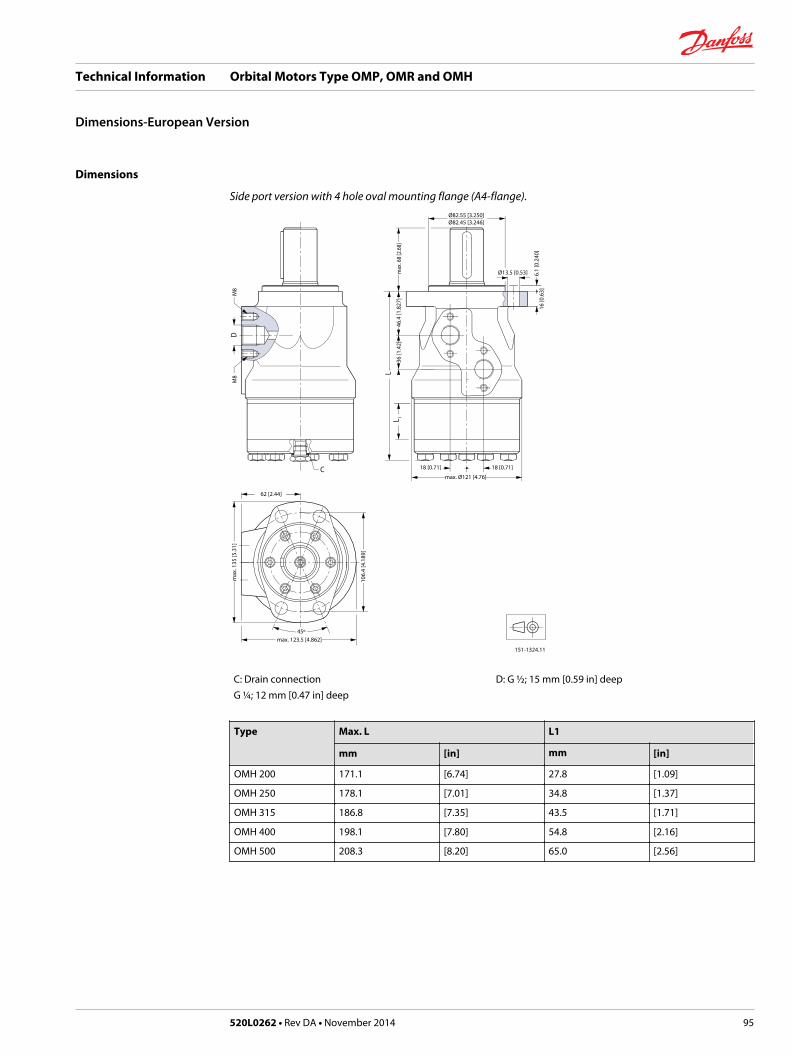
Dimensions
Side port version with 4 hole oval mounting flange (A4-flange).Ø82.55 [3.250]Ø82.45 [3.246]
Ø13.5 [0.53]
18 [0.71]18 [0.71]
max. Ø121 [4.76]
106.
4 [4
.189
]
151-1324.11
16 [0
.63]
6.1
[0.2
40]
46.4
[1.8
27]
36 [1
.42]
max
. 68
[2.6
8]
62 [2.44]
max. 123.5 [4.862]45º
max
. 135
[5.3
1]
C
LL 1
DM
8M
8
C: Drain connectionG ¼; 12 mm [0.47 in] deep
D: G ½; 15 mm [0.59 in] deep
Type Max. L L1
mm [in] mm [in]
OMH 200 171.1 [6.74] 27.8 [1.09]
OMH 250 178.1 [7.01] 34.8 [1.37]
OMH 315 186.8 [7.35] 43.5 [1.71]
OMH 400 198.1 [7.80] 54.8 [2.16]
OMH 500 208.3 [8.20] 65.0 [2.56]
Technical Information Orbital Motors Type OMP, OMR and OMH
Dimensions-European Version
520L0262 • Rev DA • November 2014 95

Dimensions
Side port version with 4 hole oval mounting flange (A4 flange).Ø82.55 [3.250]Ø82.45 [3.246]
Ø13.5 [0.53]
18 [0.71]18 [0.71]
max. Ø121 [4.76]
106.
4 [4
.189
]
151-1324.11
16 [0
.63]
6.1
[0.2
40]
46.4
[1.8
27]
36 [1
.42]
max
. 68
[2.6
8]
62 [2.44]
max. 123.5 [4.862]45º
max
. 135
[5.3
1]
C
LL 1
DM
8M
8
C: Drain connection7⁄16 - 20 UNF;12 mm [0.47 in] deep
D: 7⁄8 - 14 UNF;15 mm [0.59 in] deep
Output shaft.max. L2
mm [in]
Splined shaft 1 in 50.5 [1.99]
Other shaft versions 58.0 [2.28]
Type Max. L L1
mm [in] mm [in]
OMH 200 171.1 [6.74] 27.8 [1.09]
OMH 250 178.1 [7.01] 34.8 [1.37]
OMH 315 186.8 [7.35] 43.5 [1.71]
OMH 400 198.1 [7.80] 54.8 [2.16]
OMH 500 208.3 [8.20] 65.0 [2.56]
Technical Information Orbital Motors Type OMP, OMR and OMH
Dimensions-US Version
96 520L0262 • Rev DA • November 2014

Weight of Motors
Code no Weight
kg [lb]
151-0208 7.2 [15.9]
151-0242 6.9 [15.2]
151-0243 7.0 [15.4]
151-0244 7.5 [16.5]
151-0245 8.0 [17.6]
151-0246 9.0 [19.8]
151-0247 8.5 [18.7]
151-0248 6.7 [14.8]
151-0265 6.7 [14.8]
151-0266 6.9 [15.2]
151-0267 7.0 [15.4]
151-0268 7.5 [16.5]
151-0269 8.0 [17.6]
151-0270 9.0 [19.8]
151-0271 8.5 [18.7]
151-0300 5.6 [12.3]
151-0301 5.7 [12.6]
151-0302 5.9 [13.0]
151-0303 6.0 [13.2]
151-0304 6.2 [13.7]
151-0305 6.4 [14.1]
151-0306 6.6 [14.6]
151-0307 6.9 [15.2]
151-0308 7.4 [16.3]
151-0310 5.6 [12.3]
151-0311 5.7 [12.6]
151-0312 5.9 [13.0]
151-0313 6.0 [13.2]
151-0314 6.2 [13.7]
151-0315 6.4 [14.1]
151-0316 6.6 [14.6]
151-0317 6.9 [15.2]
151-0318 7.4 [16.3]
151-0319 5.6 [12.3]
151-0330 5.6 [12.3]
151-0331 5.7 [12.6]
151-0332 5.9 [13.0]
151-0333 6.0 [13.2]
151-0334 6.2 [13.7]
Technical Information Orbital Motors Type OMP, OMR and OMH
Weight of motors
520L0262 • Rev DA • November 2014 97

Code no Weight
kg [lb]
151-0335 6.4 [14.1]
151-0336 6.6 [14.6]
151-0337 6.9 [15.2]
151-0338 7.4 [16.3]
151-0340 5.5 [12.1]
151-0341 5.5 [12.1]
151-0342 5.6 [12.3]
151-0400 6.7 [14.8]
151-0401 6.9 [15.2]
151-0402 7.0 [15.4]
151-0403 7.2 [15.9]
151-0404 7.5 [16.5]
151-0405 8.0 [17.6]
151-0406 8.5 [18.7]
151-0407 9.0 [19.8]
151-0408 9.5 [20.9]
151-0410 6.7 [14.8]
151-0411 6.9 [15.2]
151-0412 7.0 [15.4]
151-0413 7.2 [15.9]
151-0414 7.5 [16.5]
151-0415 8.0 [17.6]
151-0416 8.5 [18.7]
151-0417 9.0 [19.8]
151-0418 9.5 [20.9]
151-0420 6.7 [14.8]
151-0421 6.9 [15.2]
151-0422 7.0 [15.4]
151-0423 7.2 [15.9]
151-0424 7.5 [16.5]
151-0425 8.0 [17.6]
151-0426 8.5 [18.7]
151-0427 9.0 [19.8]
151-0428 9.5 [20.9]
151-0600 5.6 [12.3]
151-0601 5.7 [12.6]
151-0602 5.9 [13.0]
151-0603 6.0 [13.2]
151-0604 6.2 [13.7]
151-0605 6.4 [14.1]
151-0606 6.6 [14.6]
151-0607 6.9 [15.2]
Technical Information Orbital Motors Type OMP, OMR and OMH
Weight of motors
98 520L0262 • Rev DA • November 2014

Code no Weight
kg [lb]
151-0608 7.4 [16.3]
151-0610 5.6 [12.3]
151-0611 5.7 [12.6]
151-0612 5.9 [13.0]
151-0613 6.0 [13.2]
151-0614 6.2 [13.7]
151-0615 6.4 [14.1]
151-0616 6.6 [14.6]
151-0617 6.9 [15.2]
151-0618 7.4 [16.3]
151-0622 5.9 [13.0]
151-0624 6.2 [13.7]
151-0625 6.4 [14.1]
151-0627 6.9 [15.2]
151-0630 5.6 [12.3]
151-0631 5.7 [12.6]
151-0632 5.9 [13.0]
151-0633 6.0 [13.2]
151-0634 6.2 [13.7]
151-0635 6.4 [14.1]
151-0636 6.6 [14.6]
151-0637 6.9 [15.2]
151-0638 7.4 [16.3]
151-0640 5.5 [12.1]
151-0641 5.5 [12.1]
151-0642 5.6 [12.3]
151-0646 5.9 [13.0]
151-0700 6.7 [14.8]
151-0701 6.9 [15.2]
151-0702 7.0 [15.4]
151-0703 7.2 [15.9]
151-0704 7.5 [16.5]
151-0705 8.0 [17.6]
151-0706 8.5 [18.7]
151-0707 9.0 [19.8]
151-0708 9.5 [20.9]
151-0710 6.7 [14.8]
151-0711 6.9 [15.2]
151-0712 7.0 [15.4]
151-0713 7.2 [15.9]
151-0714 7.5 [16.5]
151-0715 8.0 [17.6]
Technical Information Orbital Motors Type OMP, OMR and OMH
Weight of motors
520L0262 • Rev DA • November 2014 99

Code no Weight
kg [lb]
151-0716 8.5 [18.7]
151-0717 9.0 [19.8]
151-0718 9.5 [20.9]
151-0720 6.7 [14.8]
151-0721 6.9 [15.2]
151-0722 7.0 [15.4]
151-0723 7.2 [15.9]
151-0724 7.5 [16.5]
151-0725 8.0 [17.6]
151-0726 8.5 [18.7]
151-0727 9.0 [19.8]
151-0728 9.5 [20.9]
151-1208 5.6 [12.3]
151-1209 5.7 [12.6]
151-1210 5.9 [13.0]
151-1211 6.2 [13.7]
151-1212 6.4 [14.1]
151-1213 6.6 [14.6]
151-1214 6.9 [15.2]
151-1215 7.4 [16.3]
151-1217 6.0 [13.2]
151-1231 6.7 [14.8]
151-1232 6.9 [15.2]
151-1233 7.0 [15.4]
151-1234 7.5 [16.5]
151-1235 8.0 [17.6]
151-1236 8.5 [18.7]
151-1237 9.0 [19.8]
151-1238 7.2 [15.9]
151-1243 9.5 [20.9]
151-5001 5.6 [12.3]
151-5002 5.7 [12.6]
151-5003 5.9 [13.0]
151-5004 6.0 [13.2]
151-5005 6.2 [13.7]
151-5006 6.4 [14.1]
151-5007 6.6 [14.6]
151-5008 6.9 [15.2]
151-5009 7.4 [16.3]
151-5010 5.4 [11.9]
151-5174 5.4 [11.9]
151-5191 6.1 [13.4]
Technical Information Orbital Motors Type OMP, OMR and OMH
Weight of motors
100 520L0262 • Rev DA • November 2014

Code no Weight
kg [lb]
151-5192 6.2 [13.7]
151-5193 6.4 [14.1]
151-5194 6.5 [14.3]
151-5195 6.7 [14.8]
151-5196 6.9 [15.2]
151-5197 7.1 [15.7]
151-5198 7.4 [16.3]
151-5199 7.9 [17.4]
151-5211 5.5 [12.1]
151-5212 5.6 [12.3]
151-5213 5.8 [12.8]
151-5214 5.9 [13.0]
151-5215 6.1 [13.4]
151-5216 6.3 [13.9]
151-5217 6.5 [14.3]
151-5218 6.8 [15.0]
151-5219 7.3 [16.1]
151-5301 5.5 [12.1]
151-5302 5.6 [12.3]
151-5303 5.8 [12.8]
151-5304 5.9 [13.0]
151-5305 6.1 [13.4]
151-5306 6.3 [13.9]
151-5307 6.5 [14.3]
151-5308 6.8 [15.0]
151-5309 7.3 [16.1]
151-5311 5.6 [12.3]
151-5312 5.7 [12.6]
151-5313 5.9 [13.0]
151-5315 6.2 [13.7]
151-5316 6.4 [14.1]
151-5318 6.9 [15.2]
151-6000 6.7 [14.8]
151-6001 6.9 [15.2]
151-6002 7.0 [15.4]
151-6003 7.2 [15.9]
151-6004 7.5 [16.5]
151-6005 8.0 [17.6]
151-6006 8.5 [18.7]
151-6007 9.0 [19.8]
151-6008 9.5 [20.9]
151-6010 6.7 [14.8]
Technical Information Orbital Motors Type OMP, OMR and OMH
Weight of motors
520L0262 • Rev DA • November 2014 101

Code no Weight
kg [lb]
151-6011 6.9 [15.2]
151-6012 7.0 [15.4]
151-6013 7.2 [15.9]
151-6014 7.5 [16.5]
151-6015 8.0 [17.6]
151-6016 8.5 [18.7]
151-6017 9.0 [19.8]
151-6018 9.5 [20.9]
151-6110 6.7 [14.8]
151-6111 6.9 [15.2]
151-6112 7.0 [15.4]
151-6113 7.2 [15.9]
151-6114 7.5 [16.5]
151-6115 8.0 [17.6]
151-6116 8.5 [18.7]
151-6117 9.0 [19.8]
151-6118 9.5 [20.9]
151-6190 7.3 [16.1]
151-6191 7.5 [16.5]
151-6192 7.6 [16.8]
151-6193 7.8 [17.2]
151-6194 8.1 [17.9]
151-6195 8.6 [19.0]
151-6196 9.1 [20.1]
151-6197 9.6 [21.2]
151-6198 10.1 [22.3]
151-6210 6.7 [14.8]
151-6211 6.9 [15.2]
151-6212 7.0 [15.4]
151-6213 7.2 [15.9]
151-6214 7.5 [16.5]
151-6215 8.0 [17.6]
151-6216 8.5 [18.7]
151-6217 9.0 [19.8]
151-6218 9.5 [20.9]
151-6294 9.5 [20.9]
151-6295 7.2 [15.9]
151-6296 9.5 [20.9]
151-6300 9.0 [19.8]
151-6301 9.4 [20.7]
151-6302 9.5 [20.9]
151-6303 9.7 [21.4]
Technical Information Orbital Motors Type OMP, OMR and OMH
Weight of motors
102 520L0262 • Rev DA • November 2014

Code no Weight
kg [lb]
151-6304 10.0 [22.1]
151-6305 10.5 [23.1]
151-6306 11.0 [24.3]
151-6307 11.5 [25.4]
151-6308 12.0 [26.5]
151-6380 6.7 [14.8]
151-6381 6.9 [15.2]
151-6383 7.2 [15.9]
151-6384 7.5 [16.5]
151-6385 8.0 [17.6]
151-6386 8.5 [18.7]
151-6387 9.0 [19.8]
151-6388 9.5 [20.9]
151-6430 9.0 [19.8]
151-6431 9.4 [20.7]
151-6432 9.5 [20.9]
151-6433 9.7 [21.4]
151-6434 10.0 [22.1]
151-6435 10.5 [23.1]
151-6436 11.0 [24.3]
151-6437 11.5 [25.4]
151-6438 12.0 [26.5]
151-6442 14.5 [32.0]
151-6443 14.7 [32.4]
151-6444 15.0 [33.1]
151-6445 15.5 [34.2]
151-6461 11.5 [25.4]
151-6462 12.0 [26.5]
151-6463 12.0 [26.5]
151-6464 12.5 [27.6]
151-6465 12.5 [27.6]
151-6466 13.0 [28.7]
151-6467 13.5 [29.8]
151-6468 14.0 [30.9]
151-6471 11.5 [25.4]
151-6472 12.0 [26.5]
151-6473 12.0 [26.5]
151-6474 12.5 [27.6]
151-6475 12.5 [27.6]
151-6476 13.0 [28.7]
151-6477 13.5 [29.8]
151-6478 14.0 [30.9]
Technical Information Orbital Motors Type OMP, OMR and OMH
Weight of motors
520L0262 • Rev DA • November 2014 103

Code no Weight
kg [lb]
151-7021 5.0 [11.0]
151-7022 5.1 [11.2]
151-7023 5.3 [11.7]
151-7024 5.4 [11.9]
151-7025 5.6 [12.3]
151-7026 5.8 [12.8]
151-7027 6.0 [13.2]
151-7028 6.3 [13.9]
151-7029 6.8 [15.0]
151-7041 5.6 [12.3]
151-7042 5.7 [12.6]
151-7043 5.9 [13.0]
151-7044 5.4 [11.9]
151-7045 6.2 [13.7]
151-7046 6.4 [14.1]
151-7047 6.6 [14.6]
151-7048 6.9 [15.2]
151-7049 7.4 [16.3]
151-7061 5.0 [11.0]
151-7062 5.1 [11.2]
151-7063 5.3 [11.7]
151-7065 5.6 [12.3]
151-7066 5.8 [12.8]
151-7067 6.0 [13.2]
151-7068 6.3 [13.9]
151-7069 6.8 [15.0]
151-7080 5.4 [12.0]
151-7081 5.4 [12.0]
151-7082 5.6 [12.3]
151-7101 5.5 [12.1]
151-7102 5.6 [12.3]
151-7103 5.8 [12.8]
151-7104 5.9 [13.0]
151-7105 6.1 [13.4]
151-7106 6.3 [13.9]
151-7107 6.5 [14.3]
151-7108 6.8 [15.0]
151-7109 7.3 [16.1]
151-7240 6.7 [14.8]
151-7241 6.9 [15.2]
151-7242 7.0 [15.4]
151-7243 7.2 [15.9]
Technical Information Orbital Motors Type OMP, OMR and OMH
Weight of motors
104 520L0262 • Rev DA • November 2014

Code no Weight
kg [lb]
151-7244 7.5 [16.5]
151-7245 8.0 [17.6]
151-7246 8.5 [18.7]
151-7247 9.0 [19.8]
151-7248 9.5 [20.9]
151-7250 6.7 [14.8]
151-7251 6.9 [15.2]
151-7252 7.0 [15.4]
151-7253 7.2 [15.9]
151-7254 7.5 [16.5]
151-7255 8.0 [17.6]
151-7256 8.5 [18.7]
151-7257 9.0 [19.8]
151-7258 9.5 [20.9]
151-7260 6.1 [13.4]
151-7261 6.3 [13.9]
151-7262 6.4 [14.1]
151-7263 6.6 [14.6]
151-7264 6.9 [15.2]
151-7265 7.4 [16.3]
151-7266 7.9 [17.4]
151-7267 8.4 [18.5]
151-7269 8.9 [19.6]
151H1002 10.5 [23.1]
151H1003 11.0 [24.3]
151H1004 11.5 [25.4]
151H1005 12.3 [27.1]
151H1006 13.0 [28.7]
151H1012 10.5 [23.1]
151H1013 11.0 [24.3]
151H1014 11.5 [25.4]
151H1015 12.3 [27.1]
151H1016 13.0 [28.7]
151H1022 10.5 [23.1]
151H1023 11.0 [24.3]
151H1024 11.5 [25.4]
151H1025 12.3 [27.1]
151H1026 13.0 [28.7]
151H1034 11.5 [25.4]
151H1035 12.3 [27.1]
151H1036 13.0 [28.7]
151H1042 10.5 [23.1]
Technical Information Orbital Motors Type OMP, OMR and OMH
Weight of motors
520L0262 • Rev DA • November 2014 105

Code no Weight
kg [lb]
151H1043 11.0 [24.3]
151H1044 11.5 [25.4]
151H1045 12.3 [27.1]
151H1046 13.0 [28.7]
151H1052 10.5 [23.1]
151H1053 11.0 [24.3]
151H1054 11.5 [25.4]
151H1055 12.3 [27.1]
151H1056 13.0 [28.7]
151H1080 10.5 [23.1]
151H1081 13.0 [28.7]
151H1082 11.0 [24.3]
151H1083 11.5 [25.4]
151H1084 12.3 [27.1]
Technical Information Orbital Motors Type OMP, OMR and OMH
Weight of motors
106 520L0262 • Rev DA • November 2014

Technical Information Orbital Motors Type OMP, OMR and OMH
520L0262 • Rev DA • November 2014 107
Danfoss Power Solutions is a global manufacturer and supplier of high-quality hydraulic andelectronic components. We specialize in providing state-of-the-art technology and solutionsthat excel in the harsh operating conditions of the mobile off-highway market. Building onour extensive applications expertise, we work closely with our customers to ensureexceptional performance for a broad range of off-highway vehicles.
We help OEMs around the world speed up system development, reduce costs and bringvehicles to market faster.
Danfoss – Your Strongest Partner in Mobile Hydraulics.
Go to www.powersolutions.danfoss.com for further product information.
Wherever off-highway vehicles are at work, so is Danfoss. We offer expert worldwide supportfor our customers, ensuring the best possible solutions for outstanding performance. Andwith an extensive network of Global Service Partners, we also provide comprehensive globalservice for all of our components.
Please contact the Danfoss Power Solution representative nearest you.
Local address:
Danfoss Power Solutions GmbH & Co. OHGKrokamp 35D-24539 Neumünster, GermanyPhone: +49 4321 871 0
Danfoss Power Solutions ApSNordborgvej 81DK-6430 Nordborg, DenmarkPhone: +45 7488 2222
Danfoss Power Solutions (US) Company2800 East 13th StreetAmes, IA 50010, USAPhone: +1 515 239 6000
Danfoss Power Solutions(Shanghai) Co., Ltd.Building #22, No. 1000 Jin Hai RdJin Qiao, Pudong New DistrictShanghai, China 201206Phone: +86 21 3418 5200
Danfoss can accept no responsibility for possible errors in catalogues, brochures and other printed material. Danfoss reserves the right to alter its products without notice. This also applies toproducts already on order provided that such alterations can be made without changes being necessary in specifications already agreed.All trademarks in this material are property of the respective companies. Danfoss and the Danfoss logotype are trademarks of Danfoss A/S. All rights reserved.
520L0262 • Rev DA • November 2014 www.danfoss.com © Danfoss A/S, 2014
Products we offer:
• Bent Axis Motors
• Closed Circuit Axial PistonPumps and Motors
• Displays
• Electrohydraulic PowerSteering
• Electrohydraulics
• Hydraulic Power Steering
• Integrated Systems
• Joysticks and ControlHandles
• Microcontrollers andSoftware
• Open Circuit Axial PistonPumps
• Orbital Motors
• PLUS+1® GUIDE
• Proportional Valves
• Sensors
• Steering
• Transit Mixer Drives
Comatrolwww.comatrol.com
Schwarzmüller-Inverterwww.schwarzmueller-inverter.com
Turolla www.turollaocg.com
Valmovawww.valmova.com
Hydro-Gearwww.hydro-gear.com
Daikin-Sauer-Danfosswww.daikin-sauer-danfoss.com
Top Related