


Languages
Pages
Legal


Turbocompressors for Domestic Heat Pumps – A Critical Review
J. Schiffmanna*, J.B. Carréa, C. Arpagausb, S. Bertschb
a Laboratory for Applied Mechanical Design, Ecole Polytechnique Fédérale de Lausanne,
Rue de la Maladière 71b, Neuchâtel, 2000, Switzerland bNTB University of Applied Sciences of Technology Buchs, Institute for Energy Systems, Werdenbergstrasse 4, 9471 Buchs, Switzerland
Abstract
Small-scale, oil-free radial compressors on gas lubricated bearings represent a promising alternative to state-of-
the-art compressor technology for driving domestic sized heat pumps. The inherent characteristics of
turbocompressors manage to fit the heat pump load while the oil-freeness allows the implementation of advanced
heat exchanger technology and the deployment of advanced multi-stage cycles, both validated means to
significantly enhance performance and efficiency.
The paper presents experimental investigations and results of both electrically and thermally driven 20mm 2kW
radial compressor rotating at rotor speeds of up to 210krpm. The compressor stage has been tested in R134a,
reaching isentropic efficiencies above 70%. Dynamic, gas lubricated bearings are supporting the high-speed
rotors that are lubricated with vapor phase working fluid, thus offering an oil-free and hermetic solution. Insights
into the experimental investigation of a 6kW two-stage radial compressor for driving retrofit heat pumps with
high temperature lifts are introduced as well.
Besides comparing experimental data, the paper also sheds light into critical design aspects related to reduced
scale machines and compares them with regards to their impact on efficiency. Identified key issues are (1)
aerodynamic challenges related to the severe downscaling of radial compressors such as tip clearance, surface
roughness and non-adiabatic operation (2) stable gas bearing technology and (3) challenges related to high power
density designs.
© 2017 Stichting HPC 2017.
Selection and/or peer-review under responsibility of the organizers of the 12th IEA Heat Pump Conference 2017.
Keywords: residential heat pump; small-scale oil-free turbocompressors; gas bearings; radial compressors
1 Introduction
According to IEA residential heating and hot tap water production account for 20% of the total worldwide
primary energy consumption [1]. Heating and cooling only need relatively low temperature levels, hence
renewable energy sources offer an interesting alternative to fossil fuels. In view of categorizing promising
technological combinations to provide residential heating Favrat et al. [2] clearly identify heat pumps as a key
technology for reducing energy consumption for heating services. More recent work by Demierre et al. [3, 4] and
by Mounier et al. [5] show further interesting alternatives to absorption heat pumps based on Organic Rankine
Cycles directly driving a vapour compression heat pump cycle.
Although heat pump technology is widely spread in the residential sector a significant potential is still
unexplored to improve its performance. The performance has increased significantly with the introduction of
scroll compressor in the early nineties but has mainly been stagnating after that surge. Marginal improvements
* Corresponding author. Tel.: +41 21 695 45 48.
E-mail address: [email protected]

Schiffmann et al. / 12th IEA Heat Pump Conference (2017) O.1.6.1
2
have been achieved mainly with enhanced controlling [6].
Based on this background the question rises whether a new step change can be introduced to further improve
heat pump performance. An exergetic analysis by Zehnder [7] suggests that approximately 50% of the exergetic
losses occur during the compression process, 30% are due to the expansion process whereas the remainder 20%
occur during the heat transfer. A key enabler to enhance the heat pump performance is therefore to improve the
compression efficiency. This can be achieved either through novel compressor technology and/or by splitting the
compression process into several stages in combination with intercooling.
This is underlined through recent work by Arpagaus et al. [8] who suggest that multi-stage vapour compression
cycles with open economizer offer the highest gain in Coefficient of Performance (COP) compared to state of the
art cycles. Both the intercooled compression process and the two-stage expansion decrease the net cycles losses.
A key challenge of multi-stage compression cycles with conventional components, i.e positive displacement
compressors, is the oil-migration within the cycle. Oil needed for lubrication and sealing of the compressor is
dragged along with the working fluid and therefore contaminates both cycle and heat exchangers. Experimental
investigation by Zehnder [7] on a two-stage heat pump driven by two scroll compressors shows that no self
stabilizing configuration could be found without an additional oil management system. In addition, the presence
of oil in the heat exchangers is suggested to increase both pressure losses and the thermal resistance in particular
in the evaporator [9, 10].
It follows that heat pump performance can be best improved by combining multi-stage cycles with oil-free and
efficient compressor technology. Dynamic compression machines are known to achieve higher efficiency levels
than volumetric machines and in addition, no oil is needed for sealing. Hence, combining a turbocompressor
with oil-free bearings has been identified as a promising technology to further boost heat pump performance. As
an example, Turbocor is well known for promoting efficient turbo compressor technology for industrial chillers.
The oil-free R134a compressor is composed of two radial compressor stages supported on magnetic bearings.
In view of targeting domestic applications oil-free single stage 2kW radial compressors have been designed and
tested by Schiffmann and Favrat [11, 12] achieving pressure ratios in excess of 3.3 and measured isentropic
efficiencies above 80%, while rotating at speeds up to 210krpm supported on gas bearings lubricated with
vapour phase R134a. More recently Carré et al. [13] have presented promising results using a two-stage radial
compressor for driving a twin-stage heat pump cycle with an open economizer for residential heating.
The objective of this article is to offer a critical review and present challenges related to directly driven small-
scale turbomachinery supported on dynamic gas-lubricated bearings for residential heating and cooling
applications.
2 Turbocompressor scaling and design issues
2.1 Scaling Analysis
In order to assess the evolution of dimensional aspects such as impeller tip, bearing and motor diameters as a
function of compressor power, a scaling analysis has been performed for a direct-driven single stage radial
compressor. The compressor is assumed to deliver the pressure ratio required for a condensation at 35°C and an
evaporation at 5°C, which corresponds to a typical application of a ground source heat pump for floor heating.
R134a has been selected as working fluid. In order to capture the effect on bearing and motor dimensions the
following assumptions have been made, based on prior work by Schiffmann and Favrat [11, 14]:
Constant DN-bearing value, length to radius and clearance to radius ratio for the bearings
Constant length to radius ratio for the rotor of the electric motor
Concerning the impeller it can be shown that the achievement of a given pressure ratio is directly linked to the
impeller tip speed [15]. It follows that the same duty can be delivered through a large low speed impeller or by a
small high-speed machine. An analysis of the aerodynamic losses, however, shows that if the impeller is too
large, disk friction on the back of the impeller depreciates performance whereas if the impeller is too small, high
relative velocity increases losses. From this follows that for a given duty (specific work and volume flow) an
optimum rotor speed and diameter can be found. In preliminary design the Balje’s charts [16] are often used to
identify the optimum impeller speed and diameter for a given set of specifications. The electric motor
dimensions can be estimated though the output equation, which is based on the concept of airgap shear stress
[17]. A constant electromechanical efficiency is assumed in order to assess the thermal heat fluxes. A
consequence of this assumption is that the specific heat flux as a result of motor losses through the stator outer
Schiffmann et al. / 12th IEA Heat Pump Conference (2017) O.1.6.1
3
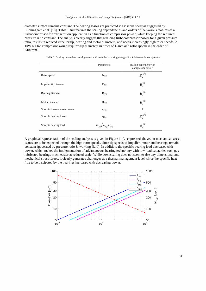
diameter surface remains constant. The bearing losses are predicted via viscous shear as suggested by
Cunningham et al. [18]. Table 1 summarizes the scaling dependencies and orders of the various features of a
turbocompressor for refrigeration application as a function of compressor power, while keeping the required
pressure ratio constant. The analysis clearly suggest that reducing turbocompressor power for a given pressure
ratio, results in reduced impeller tip, bearing and motor diameters, and needs increasingly high rotor speeds. A
1kW R134a compressor would requires tip diameters in order of 15mm and rotor speeds in the order of
240krpm.
Table 1: Scaling dependencies of geometrical variables of a single stage direct driven turbocompressor
Parameters Scaling dependency on
compressor power
Rotor speed NRot
E
K
-1 2
Impeller tip diameter DTip
E
K
1 2
Bearing diameter DBrg
E
K
1 2
Motor diameter DMot
E
K
1 2
Specific thermal motor losses qMot 1
Specific bearing losses qBrg
E
K
-1 2
Specific bearing load m
RotL
BrgD
Brg
E
K
1 2
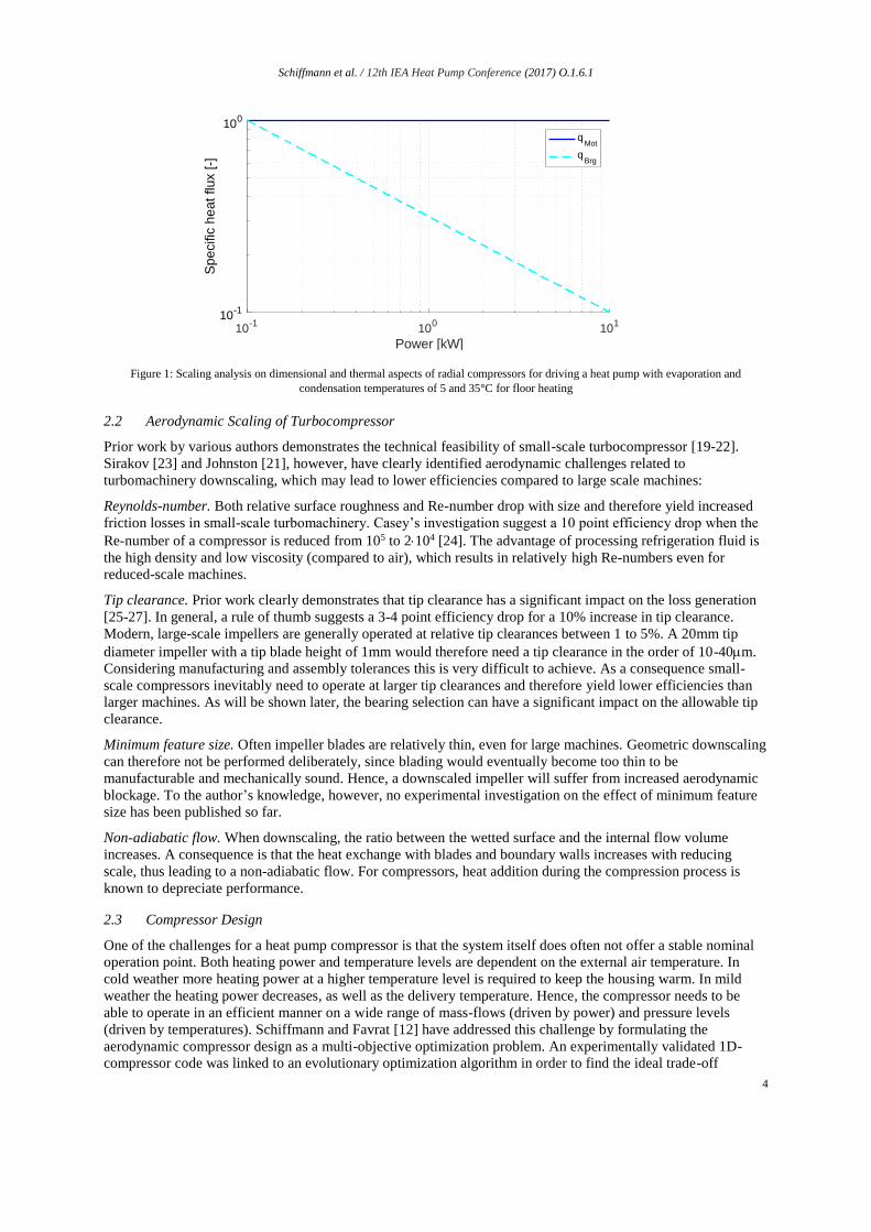
A graphical representation of the scaling analysis is given in Figure 1. As expressed above, no mechanical stress
issues are to be expected through the high rotor speeds, since tip speeds of impeller, motor and bearings remain
constant (governed by pressure ratio & working fluid). In addition, the specific bearing load decreases with
power, which makes the implementation of advantageous bearing technology with low load capacities such gas
lubricated bearings much easier at reduced scale. While downscaling does not seem to rise any dimensional and
mechanical stress issues, it clearly generates challenges at a thermal management level, since the specific heat
flux to be dissipated by the bearings increases with decreasing power.
10-1
100
101
Power [kW]
5
10
20
30
50
100
Dia
me
ter
[mm
]
50
100
200
300
500
1000
NR
ot [
krp
m]
dTip
dBrg
dMot
NNrot
Schiffmann et al. / 12th IEA Heat Pump Conference (2017) O.1.6.1
4
Figure 1: Scaling analysis on dimensional and thermal aspects of radial compressors for driving a heat pump with evaporation and
condensation temperatures of 5 and 35°C for floor heating
2.2 Aerodynamic Scaling of Turbocompressor
Prior work by various authors demonstrates the technical feasibility of small-scale turbocompressor [19-22].
Sirakov [23] and Johnston [21], however, have clearly identified aerodynamic challenges related to
turbomachinery downscaling, which may lead to lower efficiencies compared to large scale machines:
Reynolds-number. Both relative surface roughness and Re-number drop with size and therefore yield increased
friction losses in small-scale turbomachinery. Casey’s investigation suggest a 10 point efficiency drop when the
Re-number of a compressor is reduced from 105 to 2104 [24]. The advantage of processing refrigeration fluid is
the high density and low viscosity (compared to air), which results in relatively high Re-numbers even for
reduced-scale machines.
Tip clearance. Prior work clearly demonstrates that tip clearance has a significant impact on the loss generation
[25-27]. In general, a rule of thumb suggests a 3-4 point efficiency drop for a 10% increase in tip clearance.
Modern, large-scale impellers are generally operated at relative tip clearances between 1 to 5%. A 20mm tip
diameter impeller with a tip blade height of 1mm would therefore need a tip clearance in the order of 10-40m.
Considering manufacturing and assembly tolerances this is very difficult to achieve. As a consequence small-
scale compressors inevitably need to operate at larger tip clearances and therefore yield lower efficiencies than
larger machines. As will be shown later, the bearing selection can have a significant impact on the allowable tip
clearance.
Minimum feature size. Often impeller blades are relatively thin, even for large machines. Geometric downscaling
can therefore not be performed deliberately, since blading would eventually become too thin to be
manufacturable and mechanically sound. Hence, a downscaled impeller will suffer from increased aerodynamic
blockage. To the author’s knowledge, however, no experimental investigation on the effect of minimum feature
size has been published so far.
Non-adiabatic flow. When downscaling, the ratio between the wetted surface and the internal flow volume
increases. A consequence is that the heat exchange with blades and boundary walls increases with reducing
scale, thus leading to a non-adiabatic flow. For compressors, heat addition during the compression process is
known to depreciate performance.
2.3 Compressor Design
One of the challenges for a heat pump compressor is that the system itself does often not offer a stable nominal
operation point. Both heating power and temperature levels are dependent on the external air temperature. In
cold weather more heating power at a higher temperature level is required to keep the housing warm. In mild
weather the heating power decreases, as well as the delivery temperature. Hence, the compressor needs to be
able to operate in an efficient manner on a wide range of mass-flows (driven by power) and pressure levels
(driven by temperatures). Schiffmann and Favrat [12] have addressed this challenge by formulating the
aerodynamic compressor design as a multi-objective optimization problem. An experimentally validated 1D-
compressor code was linked to an evolutionary optimization algorithm in order to find the ideal trade-off
10-1
100
101
Power [kW]
10-1
100
Sp
ecific
he
at flu
x [
-]
qMot
qBrg
Schiffmann et al. / 12th IEA Heat Pump Conference (2017) O.1.6.1
5
between rotor speed and seasonal efficiency. The deviation in operating conditions was captured by expressing
the compressor efficiency as a weighted seasonal compressor performance, taking account for the occurrence of
the various operating points as a function of a selected climatic profile. Optimizations performed on individual
operation points and their comparison with the overall optimum design reveals that the wide spread of operating
conditions has a significant impact on the aerodynamic compressor design. The same approach has been
enhanced by Schiffmann [28] by including the bearing and the rotordynamic design of the complete compressor
system. The results highlight the advantage of an integrated design and optimization approach compared to the
widely spread component view philosophy.
More recently, Javed et al. [29] have analysed the effect of operational deviations of the heat pump on the
compressor map and reviewed best practice compressor design applied to a 1kW radial compressor with a 15mm
tip diameter and a vaneless diffuser. The results of the investigation clearly showed that operational deviation of
heat pumps may be challenging for radial compressors, since its operation is limited by surge and by choke
towards low and high mass flows respectively. Inlet guide vanes may be an interesting feature to further widen
the operation range of the compressor, at the cost of efficiency, though. Blading optimization using 3D CFD
suggests that a careful consideration of the blade loading distribution can have a beneficial impact on
performance, in particular when the small-scale impeller is operated at large tip clearances. CFD based results
show that an aft loaded impeller design limits the flow disturbance generated by tip clearance flow.
3 High-Speed Bearings
3.1 Bearing technology comparison
As highlighted by the scaling analysis above, turbocompressor technology for domestic scale refrigeration
applications is exposed to the requirement for rotor speeds above 100krpm. In addition, a compressor for a
domestic heat pump is supposed to achieve a lifetime above 120’000h without maintenance. These competing
objectives call for a careful bearing selection procedure. Some particular challenges related to high rotor speeds
can be summarized as follows:
Losses generally increase over-proportionally with speed, resulting in temperature gradients around and
to high temperatures in the bearing itself. Excessive temperatures may lead to a depreciation of both
material and lubricant, whereas thermal gradients may lead to excessive mechanical distortion and
eventually to failure.
Vibrations due to unbalance increase with the square of the rotational speed and need to be supported
by the bearings. Ideally, high-speed bearings offer high damping properties.
Centrifugal forces also increase with the square of the rotational speed and generate mechanical stress
in the rotor, thus limiting the maximum rotor and bearing diameter.
Lubrication. The high rotational speeds generate strong windage velocities that may endanger the
continuous supply of lubricant. A situation may occur where some of the relevant surfaces are not
supplied with lubricant, which would lead to pre-mature failure.
Depending on the application different bearing technologies can be envisaged for high-speed rotors. As an
example, the designer of a drilling spindle for printed circuit boards will focus more on load capacity and
stiffness whereas for a turbocompressor minimal losses, life time and reliability are more important features.
Bearing technologies used in high-speed systems can be subdivided into the following categories:
Rolling Element Bearing (REB) are widely spread and robust technology. The main advantages are that
it can support loads down to zero speed, its compactness and the fact that they are easily available in
normalized sizes. REB presents no cross-coupled stiffness and is therefore inherently stable. Lifetime
expectation reduces significantly with rotor speed since the inertial forces generated by the rolling
elements may exceed the rotor loading. Unfortunately, they require oil or grease based lubrication,
which can be a problem if contamination with hydrocarbons is an issue.
Active Magnetic Bearing (AMB). The rotor levitates in a magnetic field without any contamination of
the fluid. The bearing system is large compared to other technologies, since it requires touchdown
bearings in case of power failure and an auxiliary feedback control with proximity probes and controller
[30]. Stacked laminations are required on the rotor in order to decrease eddy current and hysteresis
losses. These shrink-fitted laminations on the rotor do not contribute to the flexural rotor stiffness and
therefore decrease the natural bending frequency. Hence, high-speed rotors on AMB are often ran
overcritical. The relative space requirement increases with decreasing rotor size and therefore makes

Schiffmann et al. / 12th IEA Heat Pump Conference (2017) O.1.6.1
6
these systems less interesting for very small applications. In addition, the overall unit becomes more
complex and expensive compared to other passive technologies.
Fluid Film Bearing (FFB). The lubricating fluid can be of incompressible or compressible nature. The
advantages of gaseous over liquid lubricants lies most of all in the cleanliness and in the elimination of
contamination caused by liquid lubricants. Furthermore seals can be avoided as the processed gas is
generally usable as the bearing’s lubricant. A non-negligible advantage of gas over liquid is the wide
temperature range without relevant changes in properties. The lower viscosity and density of gas
compared to liquids, however, considerably decrease the bearing load capacity and damping. The lower
viscosity, however, decreases the mechanical losses enabling much higher surface speeds. Externally
pressurized bearings require an external source of pressurized gas or liquid, needing an auxiliary pump
or compressor, which represents a net energy consumption and a significant reduction of the total
system efficiency. Dynamic fluid film bearings generate load capacity through the rotation of the shaft
and therefore require no auxiliary systems. As these bearing types generate no load capacity and
stiffness at zero speed the material selection is an important part of the deign process to avoid any
damage related to stop & go cycles.
The comparison of technology clearly suggests that neither REB nor AMB correspond to an ideal choice for
reduced scale, high-speed turbomachinery for energy conversion systems. REBs due to their limited life
expectation and the potential contamination of the processed fluid with grease or oil, AMBs due to their
complexity and requirement of auxiliary elements. It follows that small-scale turbomachinery would ideally be
based on fluid film bearings lubricated with a compressible fluid, ideally with the gas processed through the
machine. Further, the gas lubricated fluid film bearing should be of dynamic type in order to avoid additional
energy consumption.
3.2 Gas lubricated bearings
The first theoretical investigations concerning gas-lubricated bearings have been performed by Reynolds [31] in
the late 19th century. Sommerfeld [32] published first investigations on hydrodynamic lubrication and Harrison
[33] developed the lubrication theory using compressible fluids as lubricant. The main drawback of gas-
lubricated bearings is their cross-coupled behavior, which drives the rotor into a whirling orbit. Depending on
the whirling velocity and the rotor mass the orbit size can increase with time, hence leading to an unstable
behavior. The low stability margins of plain journal bearings motivated the research to offset the low stability
threshold. An interesting overview of gas bearing technologies is given by Fuller [34]. The main technologies
with interesting load capacity, stability and loss characteristics are foil bearings (FB) and the herringbone
grooved journal bearings (HGJB), which can also be implemented as thrust bearings. The two technologies
follow different philosophies to increase the stability threshold.
FBs are generally composed of thin metal foils (Figure 2, right), which are shaped such as to offer a compliant
structure [35]. The motion of the spinning rotor is then used to act on the compliant structure and to deform it
elastically. The deformation and the induced relative motion between foils generates Coulomb friction, which is
suggested to produce damping, and thus stabilize the bearing [36]. The consequence of this working principle is
that the rotor assembly needs to be able to work on large orbits, which seen from a perspective of the
turbocompressor results in increased relative tip clearance and increased losses. The compliant mechanical
structure, though, makes the bearing tolerant to misalignment errors and enables it to cope with significant
thermal gradients. Recent investigations in foil bearings present means to improve the FB stability threshold by
increasing the damping capabilities through the use of metal meshes [37] or by tailoring the fluid film through
selective shimming [38].
HGJB are composed of two counteracting helicoidal pumping grooves (Figure 2, left), which increase the
pressure within the fluid film and thus increase the stability threshold [14, 39]. The rigid mounting and the small
bearing clearances (C/D ≈ 0.001) require tight manufacturing tolerances, perfect alignment and particular
attention with regards to thermal management to avoid large thermal gradients across the bearing clearance.
However, since the bearings are generally rigidly mounted, the compressor can be run at tight tip clearances and
therefore limit the efficiency penalty at reduced scale.

Schiffmann et al. / 12th IEA Heat Pump Conference (2017) O.1.6.1
7
Figure 2: Examples of a 10mm herringbone grooved journal bearing for a 280krpm 1kW compressor (left) and of a 40mm foil bearings
(right) designed, manufactured and tested at EPFL.
One of the main considerations in designing small-scale, high-speed gas bearing supported rotors is to control
the forced response and to avoid rotordynamic instability. The forced response is mainly driven through
unbalance and can easily be controlled by appropriate balancing procedures. The onset of instability can be
monitored, however, the orbit amplitudes often increase very rapidly with rotor speed, barely leaving enough
time to react to avoid catastrophic bearing failure [40]. Further, since gas-lubricated bearing offer only limited
damping, crossing critical speeds involving flexural bending is very difficult. Only one example is known in
literature so far for a foil bearing supported rotor [41]. An additional complication comes from the fact that both
stiffness and damping matrices of fluid film bearings not only depend on rotor speed but also on the excitation
frequency. As a consequence an appropriate rotordynamic model of a gas bearing supported rotor is required to
predict critical speeds, modes, unbalance response and stability margins and to design an appropriate small scale
turbocompressor system [42].
4 Experimental Results
4.1 Single stage proof-of-concept compressor
An electrically driven single stage proof-of-concept compressor for R134a has been designed, manufactured and
successfully tested by Schiffmann and Favrat [11], which, to the author’s knowledge, represents the first
experimental evidence of the technical feasibility of a small-scale and oil-free turbocompressor for driving
domestic heat pumps. Figure 3 represents the comparison of the oil-free proof-of-concept turbocompressor
system with an equivalent scroll compressor. The turbocompressor power density is increased by one order of
magnitude compared to the positive displacement machine and offers a truly oil-free and hermetic compressor
system. The radial compressor has a tip diameter of 20mm and is supported on herringbone grooved journal
bearings lubricated with vapour R134a.
The proof-of-concept compressor has been tested in a hermetic gas-phase loop, in order to have a better control
of the compressor inlet conditions. Figure 4 represents the measured compressor map at an inlet pressure of 1.44
bara and compares the experimental data with the predictions of an in-house 1D-compressor model. Pressure
ratios in excess of 3.3 have been achieved at a rotor speed of 210krpm. In addition, good agreement is shown
between the 1D-model prediction and experimental data, suggesting that simple models based on empirical loss
correlations are a good choice for predicting radial compressor performance. This is noteworthy, since most of
the loss correlations have been derived based on large-scale impellers. Good prediction agreement is obtained, in
spite of reduced size, since the Re-number are high despite the small geometrical features as a consequence of
the high density and low viscosity of the working fluid.

Schiffmann et al. / 12th IEA Heat Pump Conference (2017) O.1.6.1
8
Figure 3: Comparison of the single-stage proof-of-concept radial compressor on gas-lubricated bearings and an equivalent scroll compressor
[12]
Figure 4: Compressor map measured at an inlet pressure of 1.44 bara (corresponding to an air temperature of -12°C) and comparison with a
1D compressor model prediction, showing good agreement between the model and experimental data [12]
4.2 Thermally driven heat pump compressor
An interesting experimental investigation has been performed by Demierre et al. [3, 4] where the same 20mm
proof-of-concept compressor has been driven by an ORC turbine rather than by an electric motor. The particular
cycle is composed of a topping Organic Rankine Cycle, which drives a bottoming vapour compression heat
pump cycle. Both the heat pump and the ORC condenser are operated at the same pressure level. The heart of
this tri-thermal cycle is the so-called compressor-turbine-unit (CTU), which is composed of a radial inflow ORC
turbine that directly drives the radial heat pump compressor. The common rotor is supported on R134a lubricated
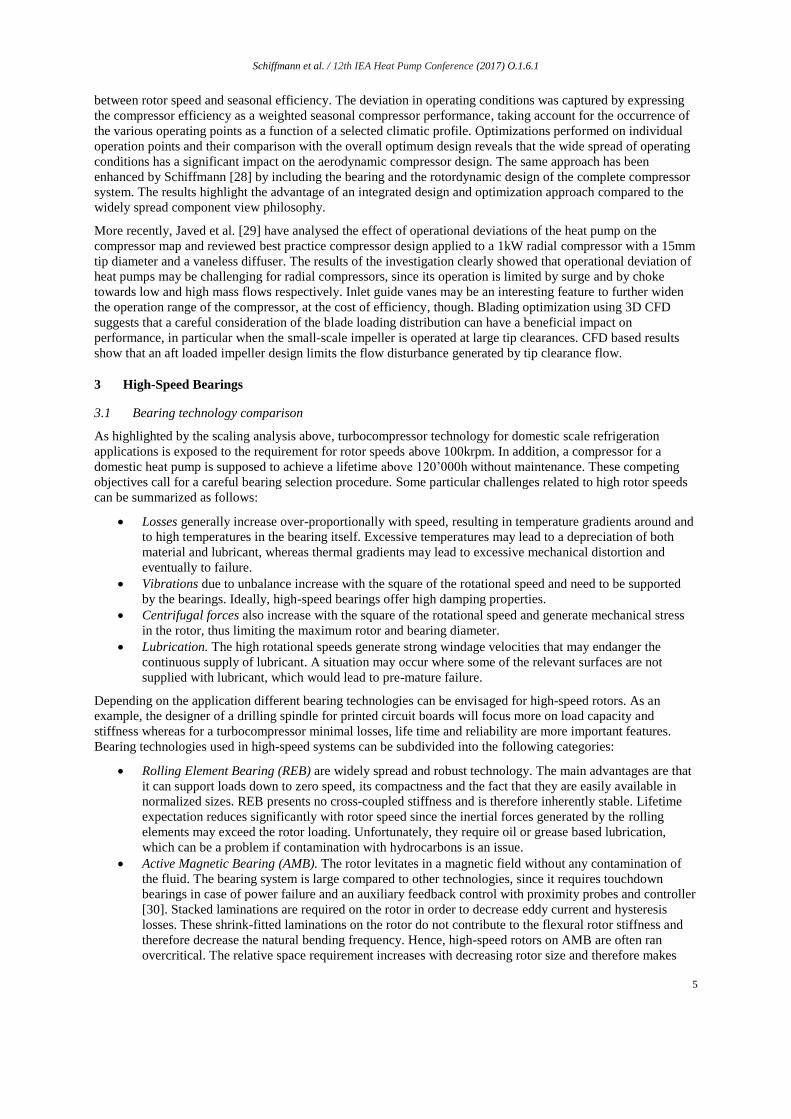
herringbone grooved journal bearings. A comparison of the isentropic compressor efficiency shown in Figure 5
reveals that the values measured with the thermally driven compressor yields significantly lower levels
compared to the ones obtained when electrically driven. Since both compressors are geometrically identical it is
hypothesized that a heat flux from the hot ORC turbine towards the cold heat pump compressor is the main cause
of the measured efficiency drop. These results are supporting the challenge to achieve adiabatic compression and
expansion processes at reduced scales.
20 25 30 35 40 45 50 55 601
1.5
2
2.5
3
3.5
Mass Flow [g/s]
P [−
]
150 krpm
160 krpm
170 krpm
180 krpm
190 krpm
200 krpm
210 krpm
Predicted
Measured
Schiffmann et al. / 12th IEA Heat Pump Conference (2017) O.1.6.1
9
Figure 5: Comparison between the predicted and measured isentropic compressor efficiency for the electrically and the thermally driven
compressor system [3]
4.3 Twin stage turbocompressor
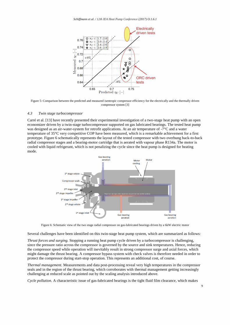
Carré et al. [13] have recently presented their experimental investigation of a two-stage heat pump with an open
economizer driven by a twin-stage turbocompressor supported on gas lubricated bearings. The tested heat pump
was designed as an air-water-system for retrofit applications. At an air temperature of -7°C and a water
temperature of 35°C very competitive COP have been measured, which is a remarkable achievement for a first
prototype. Figure 6 schematically represents the layout of the tested compressor with two overhung back-to-back
radial compressor stages and a bearing-motor cartridge that is aerated with vapour phase R134a. The motor is
cooled with liquid refrigerant, which is not penalizing the cycle since the heat pump is designed for heating
mode.
Figure 6: Schematic view of the two stage radial compressor on gas-lubricated bearings driven by a 6kW electric motor
Several challenges have been identified on this twin-stage heat pump system, which are summarized as follows:
Thrust forces and surging. Stopping a running heat pump cycle driven by a turbocompressor is challenging,
since the pressure ratio across the compressor is governed by the source and sink temperatures. Hence, reducing
the compressor speed while operation will inevitably result in strong compressor surge and axial forces, which
might damage the thrust bearing. A compressor bypass system with check valves is therefore needed in order to
protect the compressor during start-stop operation. This represents an additional cost, of course.
Thermal management. Measurements and data post-processing reveal very high temperatures in the compressor
seals and in the region of the thrust bearing, which corroborates with thermal management getting increasingly
challenging at reduced scale as pointed out by the scaling analysis introduced above.
Cycle pollution. A characteristic issue of gas-lubricated bearings is the tight fluid film clearance, which makes

Schiffmann et al. / 12th IEA Heat Pump Conference (2017) O.1.6.1
10
them prone to pollution and potentially failure. Experiments have revealed that a typical refrigeration loop is far
from being sufficiently clean for gas-lubricated bearings. Contamination occurs from the manufacturing process
of heat exchangers grease and valves. In particular oil pollution through contaminated working fluids represents
a serious challenge. As a consequence great care needs to be taken in order to avoid either contamination of the
cycle loop or at least of the bearing cartridge.
Compressor map matching. Difficulties have been reported to achieve stable heat pump operation, in particular
with regards to the economizer pressure level. A thermodynamic analysis reveals that the pressure level in the
economizer is significantly influenced by the two compressor mass-flows. It is therefore hypothesized that slight
perturbations of the two compressor maps is the cause for this issue. This is corroborated by the fact that
compressor speed lines are often very flat close to the surge line, i.e. minimal pressure ratio oscillations have a
significant effect on the delivered mass-flows. The consequence of this phenomenon is that an additional control
variable is needed to better control the matching between the two compressor stages in the heat pump loop. This
can either be achieved by individually controlled single stage compressors or possibly by variable compressor
geometry such as inlet guide vanes.
5 Conclusions
The article gives an overview of the current state of the art on direct driven small-scale turbocompressor for
domestic heat pumps. A scaling analysis clearly shows that reducing the compressor power results in smaller
impellers requiring increasingly high rotor speeds. Very high lifetime expectations and high rotor speeds are a
challenging set of specifications for the bearings. Dynamic gas-lubricated bearings have been identified as the
most promising technology for small-scale turbomachinery as a result of their low specific losses, their simple
geometry and of their potential to offer a clean and oil-free solution. A summary of published experimental data
underlines the technical feasibility of reduced scale turbocompressor for domestic heat pump applications and
identifies major technological challenges related to their operation in heat pump cycles.
Acknowledgements
The authors thank the Swiss Competence Center for Energy Research on Efficiency of Industrial Processes
(SCCER EIP) for their financial support.
Nomenaclature
C Bearing clearance (m)
DTip Compressor tip diameter (m)
DBrg Bearing diameter (m)
DMot Compressor tip diameter (m)
EK Compressor power (kW)
LBrg Bearing length (m)
NRot Rotor speed (rpm)
mRot Rotor mass (kg)
qRot Specific bearing heat flux (W/m2)
qMot Specific motor heat flux (W/m2)
Compressor pressure ratio (-)
C Compressor isentropic efficiency (-)
Acronyms
COP Coefficient of performance
CTU Compressor turbine unit
ORC Organic Rankine cycle
HGJB Herringbone grooved journal bearing
FB Foil bearing
REB Rolling element bearings
AMB Active magnetic bearings
FFB Fluid film bearings
References
1. IEA, Renewables for Heating and Cooling. 2007: International Energy Agency.
Schiffmann et al. / 12th IEA Heat Pump Conference (2017) O.1.6.1
11
2. Favrat, D., F. Marechal, and O. Epelly, The challenge of introducing an exergy indicator in a local law
on energy. Energy, 2008. 33(2): p. 130-136.
3. Demierre, J., A. Rubino, and J. Schiffmann, Modeling and Experimental Investigation of an Oil-Free
Microcompressor-Turbine Unit for an Organic Rankine Cycle Driven Heat Pump. Journal of
Engineering for Gas Turbines and Power-Transactions of the Asme, 2015. 137(3).
4. Demierre, J., et al., Experimental investigation of a Thermally Driven Heat Pump based on a double
Organic Rankine Cycle and an oil-free Compressor-Turbine Unit. International Journal of
Refrigeration-Revue Internationale Du Froid, 2014. 44: p. 91-100.
5. Mounier, V., L.C. Mendoza, and J. Schiffmann, Thermo-Economic Optimization of an ORC driven
Heat Pump based on small scale turbomachinery and Comparison with Absorption Heat Pumps.
Applied Energy, 2016.
6. Eschmann, M., Qualitätsüberwachung von Kleinwärmepumpen und statistische Auswertung 2015,
2015: Projektnummer: SI/401321-01. p. 1-24.
7. Zehnder, M., Efficient Air-Water Heat Pumps for High Temperature Lift Residential Heating, including
Oil Migration Aspects, 2004, Ecole Polytechnique Federale de Lausanne: Lausanne, Switzerland.
8. Arpagaus, C., et al., Multi-temperature heat pumps: A literature review. International Journal of
Refrigeration-Revue Internationale Du Froid, 2016. 69: p. 437-465.
9. Youbi-Idrissi, M. and J. Bonjour, The effect of oil in refrigeration: Current research issues and critical
review of thermodynamic aspects. International Journal of Refrigeration, 2008. 31: p. 165-179.
10. Youbi-Idrissi, M., et al., Oil presence in an evaporator: experimental validation of a refrigerant/oil
mixture enthalpy calculation model. International Journal of Refrigeration, 2004. 27(3): p. 215-224.
11. Schiffmann, J. and D. Favrat, Experimental Investigation of a Direct Driven Radial Compressor for
Domestic Heat Pumps. International Journal of Refrigeration, 2009. 32(8): p. 1918-1928.
12. Schiffmann, J. and D. Favrat, Design, experimental investigation and multi-objective optimization of a
small-scale radial compressor for heat pump applications. Energy, 2010. 35(1): p. 436-450.
13. Carré, J.B., D. Favrat, and J. Schiffmann, Experimental investigation of a two-stage oil-free domestic
Air/Water heat pump prototype powered by an oil-free high-speed twin-stage radial compressor
rotating on gas bearings, in 16th International Refrigeration and Air Conditioning Conference at
Purdue2016: West Lafayette IN.
14. Schiffmann, J. and D. Favrat, The effect of real gas on the properties of Herringbone Grooved Journal
Bearings. Tribology International, 2010. 43(9): p. 1602-1614.
15. Whitfield, A. and N.C. Baines, Design of Radial Turbomachines. 1990: Longman Scientific.
16. Balje, O.E., Turbomachines, A guide to Design, Selection and Theory. 1981: John Wiley \& Sons.
17. Miller, T.J.E., Switched Reluctance Motors and Their Control. 1993: Magna Physics Publishing Oxford
Science Publication, Oxford UK.
18. Cunningham, R.E., D.P. Fleming, and W.J. Anderson, Experimental Load Capacity and Power Loss of
Herringbone Grooved gas Lubricated Journal Bearings. Journal of Lubrication Technology, 1971. 93:
p. 415-422.
19. Isomura, K., et al., Experimental verification of the feasibility of 100 W class micro-scale gas turbine at
an impeller diameter of 10 mm. Journal of Micromechanics and Microengineering, 2006. 16(9): p.
S254-S261.
20. Kang, S., et al., Microscale Radial-Flow Compressor Impeller Made of Silicon Nitride: Manufacturing
and Performance. Journal of Engineering for Gas Turbines and Power, 2004. 126(2): p. 358-365.
21. Johnston, J.P., et al. Performance of a Micro-Scale Radial-Flow Compressor Impeller made of Silicon
Nitride. IGTC2003Tokyo OS-110. in International Gas Turbine Congress. 2003. Tokyo, Japan.
22. Epstein, A.H., Millimeter-Scale, Micro-Electro-Mechanical Systems Gas Turbine Engines. Journal of
Engineering for Gas Turbines and Power, 2004. 126(2): p. 205-225.
23. Sirakov, B.T., Characterization and Design of a Non-Adiabatic Micro-Compressor Impeller and
Preliminary Design of Self-Sustained Micro Engine System, 2005, Massachusetts Institute of
Technology.
24. Casey, M.V., The Effects of Reynolds Number on the Efficiency of Centrifugal Compressor Stages.
Journal of Engineering for Gas Turbines and Power, 1985. 107: p. 541-548.
25. Jansen, W. A method for calculating the flow in a centrifugal compressor impeller when entropy
gradients are present. in Royal Society conference on internal aerodynamics (turbomachinery). 1967.
Schiffmann et al. / 12th IEA Heat Pump Conference (2017) O.1.6.1
12
26. Pampreen, R.C., Small turbomachinery compressor and fan aerodynamics. Journal of Engineering for
Power, 1973. 95: p. 251-261.
27. Senoo, Y. and M. Ishida, Deterioration of compressor performance due to tip clearance on centrifugal
compressors. Journal of Turbomachinery, 1987. 109: p. 55-61.
28. Schiffmann, J., Integrated Design and Multi-objective Optimization of a Single Stage Heat-Pump
Turbocompressor. Journal of Turbomachinery-Transactions of the Asme, 2015. 137(7).
29. Javed, A., et al., Small-scale turbocompressors for wide-range operation with large tip-clearances for a
two-stage heat pump concept. International Journal of Refrigeration-Revue Internationale Du Froid,
2016. 69: p. 285-302.
30. Schweitzer, G., H. Bleuler, and A. Traxler, Magnetlager. 1992: Springer-Verlag Berlin.
31. Reynolds, O., On the Theory of Lubrication and Its Application to Mr. Beauchamp Tower's
Experiments, Including an Experimental Determination of the Viscosity of Olive Oil. Philosophical
Transactions of the Royal Society of London, 1886. 177: p. 157-234.
32. Sommerfeld, A., Zur hydrodynamischen Theorie der Schmiermittelreibung. Zeitschrift f\"{u}r
Mathematik und Physik, 1904. 50: p. 97-155.
33. Harrison, W.J., The hydrodynamical theory of lubrication with special reference to air as a lubricant.
Transactions of the Cambridge Philosophical Society, 1913. 22: p. 39-54.
34. Fuller, D.D., A Review of the State-of-the-Art for the Design of Self-Acting Gas-Lubricated Bearings.
Journal of Lubrication Technology, 1969. 91: p. 1-16.
35. Heshmat, H., Advancement in the Performance of Aerodynamic Foil Journal Bearings: High Speed and
Load Capability. ASME Journal of Tribology, 1994. 116: p. 287-295.
36. Andrés, L.S. and T.H. Kim, Analysis of gas foil bearings integrating FE top foil models. Tribology
International, 2009. 42: p. 111-120.
37. Andrés, L.S. and T.A. Chirathadam, Identification of rotordynamic force coefficients of a metal mesh
foil bearing using impact load excitations. ASME Paper No. GT2010-22440, 2010.
38. Schiffmann, J. and Z.S. Spakovszky, Foil Bearing Design Guidelines for Improved Stability. ASME
Journal of Tribology, 2013. 135(1): p. 011103.
39. Schiffmann, J., Enhanced Groove Geometry for Herringbone Grooved Journal Bearings. Journal of
Engineering for Gas Turbines and Power, 2013. 135(10): p. 102501.
40. Ehrich, F.F., Handbook of Rotordynamics. 2004, Malabar, Florida, USA: Krieger Publishing Company.
41. Heshmat, H., Operation of Foil Bearings Beyond the Bending Critical Mode. ASME Journal of
Tribology, 2000. 122: p. 192-198.
42. Schiffmann, J. and D. Favrat, Integrated Design and Optimization of Gas Bearing Supported Rotors.
ASME Journal of Mechanical Design, 2010. 132(5): p. 051007 1-11.
Top Related