


Languages
Pages
Legal


8/2/2019 Traffic Signal Field Operations
http://slidepdf.com/reader/full/traffic-signal-field-operations 1/40
Traffic Signals 101
January 2012 Topic 7: Field Operations Page 7-1
TOPIC 7: FIELD OPERATIONS
Traffic Signals 101
Topic 7
Field Operations
In this topic, you will beintroduced to the operation of signals in the field. Thisincludes controller elements
such as cycle length andphases; pedestrian timingrequirements; pre-timed andactuated signal control; andsystem control.
Field Operations
Controller Timing – A traffic signal controls traffic by
assigning right-of-way to one traffic
movement or several non-conflicting
traffic movements at a time
– Right-of-way is assigned by turning on a
green signal for a certain length of time
or an interval
– Right-of-way is ended by a yellow
change interval during which a yellow
signal is displayed, followed by the
display of a red signal
2
The objective of traffic signaltiming is to assign the right-of-way to alternating trafficmovements in such a manner to minimize the average delay
to any group of vehicles or pedestrians and reduce theprobability of accidentproducing conflicts.

8/2/2019 Traffic Signal Field Operations
http://slidepdf.com/reader/full/traffic-signal-field-operations 2/40
Traffic Signals 101
January 2012 Topic 7: Field Operations Page 7-2
Short cycle lengths typicallyyield the best performance interms of providing the lowestoverall average delayprovided the capacity of thecycle to pass vehicles is not
exceeded. The cycle length,however, must allow adequate time for vehicular and pedestrian movements .Longer cycles are used duringpeak periods to provide moregreen time for the major street, to permit larger platoons in the peak direction,and/or to reduce the number of starting delays.
Phase Change Interval
– The phase change interval timing (Yellow)
advises drivers that their phase has expired
and they should:
• come to a safe stop prior to the stop line, or;
• proceed through the intersection if they are too
near the intersection to stop
– Intersection Clearance Interval (All-Red)
• The Intersection Clearance Interval will provide a
vehicle enough time at the end of yellow to clear
before the next green is displayed
4
Field Operations
The MN MUTCD states thatthe exclusive function of thesteady yellow interval shall beto warn traffic of animpending change of right-of-way assignment. Theyellow vehicle change interval
should have a range of approximately 3 to 6 seconds.Generally the longer intervalsare appropriate to higher approach speeds. The yellowvehicle change interval shouldbe followed by a short all-wayred clearance interval, of sufficient duration to permitthe intersection to clear before cross traffic isreleased.
Minnesota Traffic Laws state
that vehicular traffic facing ayellow indication are warnedthat the related greenmovement is beingterminated or that the redindication will be exhibitedimmediately thereafter whenvehicular traffic shall not enter the intersection.

8/2/2019 Traffic Signal Field Operations
http://slidepdf.com/reader/full/traffic-signal-field-operations 3/40
Traffic Signals 101
January 2012 Topic 7: Field Operations Page 7-3
Field Operations
5
GREEN YEL. RED
RED GREEN YEL.
PHASE 1
PHASE 2
PHASE 1 SPLIT PHASE 2 SPLIT
N
CYCLE LENGTH
PHASE 1 PHASE 2
Phase 1 GreenPhase 1 YellowPhase 1 All-RedPhase 2 GreenPhase 2 YellowPhase 2 All-Red
The figure at the left showsthe timing operation for abasic two-phase or two-trafficmovement pre-timedcontroller. Note that at the
end of phase 1 and phase 2yellow, there is a short all-redclearance interval.
Pedestrian Timing
– Walk
• The MN MUTCD states, "the WALK interval should beat least 4 to 7 seconds in length so that pedestrianswill have adequate opportunity to leave the curbbefore the clearance interval is shown"
• If pedestrian volumes and characteristics do notrequire a 7-second walk interval, walk intervals asshort as 4 seconds may be used.
– Flashing Don’t Walk
• flashing DON’T WALK = D/R
6
Field Operations
The flashing DON’T WALK
interval is determined by thefollowing formula:
flashing DON’T WALK = D/R
D = Distance from the near
curb or shoulder to atleast the center of thefarthest traveled lane.
R = Walking rate of 3.5ft/sec assumedwalking rate unlessspecial conditions(school kids, elderly or handicapped) require aslower walking rate.
See topic 9 on pedestriansfor further details.

8/2/2019 Traffic Signal Field Operations
http://slidepdf.com/reader/full/traffic-signal-field-operations 4/40
Traffic Signals 101
January 2012 Topic 7: Field Operations Page 7-4
Pre-timed signal control
• Under these conditions, the signal assigns right-of-
way at an intersection according to a predetermined
schedule
• The sequence of right-of-way (phases), and the
length of the time interval for each signal indication
in the cycle is fixed, based on historic traffic patterns
7
Field Operations
No recognition is given to the current traffic demand on the intersection approaches unless detectors are used.The major elements of pre-timed control are (1) fixed cycle length, (2) fixed phase length, and (3) number andsequence of phases.
Advantages to pre-timed control include:
Simplicity of equipment provides relatively easy servicing and maintenance.
Can be coordinated to provide continuous flow of traffic at a given speed along a particular route, thusproviding positive speed control.
Timing is easily adjusted in the field.
Under certain conditions can be programmed to handle peak conditions.
Disadvantages to pre-timed control include:
Do not recognize or accommodate short-term fluctuations in traffic.
Can cause excessive delay to vehicles and pedestrians during off-peak periods.

8/2/2019 Traffic Signal Field Operations
http://slidepdf.com/reader/full/traffic-signal-field-operations 5/40
Traffic Signals 101
January 2012 Topic 7: Field Operations Page 7-5
Traffic-actuated signal control – Traffic-actuated control of isolated intersections
attempts to adjust green time continuously, and, in
some cases, the sequence of phasing
– These adjustments occur in accordance with real-time
measures of traffic demand obtained from vehicle
detectors placed on one or more of the approaches to
the intersection
8
Field Operations
The full range of actuated control capabilities depends on the type of equipment employed and the operationalrequirements.
Advantages to actuated signals include:
Usually reduce delay (if properly timed).
Adaptable to short-term fluctuations in traffic flow.
Usually increase capacity (by continually reapportioning green time).
Provide continuous operation under low volume conditions as an added safety feature, when pre-timedsignals may be put on flashing operation to prevent excessive delay.
Especially effective at multiple phase intersections.
Disadvantages to actuated control include:
The cost of an actuated installation is substantially higher than the cost of a pre-timed installation.
Actuated controllers and detectors are much more complicated than pre-timed signal controllers, increasingmaintenance and inspection skill requirements and costs.
Detectors are costly to install and require careful inspection and maintenance to ensure proper operations.
8/2/2019 Traffic Signal Field Operations
http://slidepdf.com/reader/full/traffic-signal-field-operations 6/40
Traffic Signals 101
January 2012 Topic 7: Field Operations Page 7-6
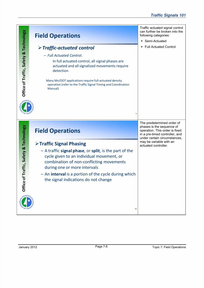
Traffic-actuated control
– Full Actuated Control .
In full actuated control, all signal phases are
actuated and all signalized movements require
detection
Many Mn/DOT applications require full-actuated density
operation (refer to the Traffic Signal Timing and Coordination
Manual)
9
Field Operations
Traffic actuated signal controlcan further be broken into thefollowing categories:
Semi-Actuated
Full Actuated Control
Traffic Signal Phasing
– A traffic signal phase, or split, is the part of thecycle given to an individual movement, or
combination of non-conflicting movements
during one or more intervals
– An interval is a portion of the cycle during which
the signal indications do not change
10
Field Operations
The predetermined order of phases is the sequence of operation. This order is fixedin a pre-timed controller, andunder certain circumstances,may be variable with anactuated controller.
8/2/2019 Traffic Signal Field Operations
http://slidepdf.com/reader/full/traffic-signal-field-operations 7/40
Traffic Signals 101
January 2012 Topic 7: Field Operations Page 7-7
Field Operations
11
PHASE 1
PHASE 2
INTERVAL
PHASE 1 PED.
PHASE 2 PED.
PHASE 1 SPLIT PHASE 2 SPLITSPLIT
GREEN
RED
WALK
DON'T WALK
1
CYCLE LENGTH
Sequence of Operation
FDW
2
YEL.
DON'T WALK
3
RED
4
GREEN
WALK
5
YEL.
7
FDW
6 8
For the figure to the left, thereare eight intervals where thesignal indications do notchange. Notice that intervals4 and 8 are all red periods(interval 4 is the phase 1 all
red and interval 8 is the phase2 all red). The phase 1 split ismade up of intervals 1through 4 and the phase 2split is made up of intervals 5through 8. The sum of split 1and 2 is the cycle length.
Actuated Controller Phase Operations
– Minimum Green Interval is the shortest greentime of a phase
– A minimum green time setting will
accommodate the lowest expected number of
vehicles that arrive per cycle
– It also allows approaching vehicles a chance to
reach detectors
12
Field Operations
Definition of the minimumgreen interval for an actuatedcontroller.
There must be a minimumgreen time so that stoppedvehicles have enough time toget started and partially cross
the intersection before theclearance interval appears.

8/2/2019 Traffic Signal Field Operations
http://slidepdf.com/reader/full/traffic-signal-field-operations 8/40
Traffic Signals 101
January 2012 Topic 7: Field Operations Page 7-8
– Passage Time (vehicle extension or gap time) is
the time that the green phase will be extended
for each actuation
13
Field Operations
Passage time (vehicleextension or gap time) istypically set as the time ittakes to travel from thevehicle detector to the stopline at the travel speed of the
roadway for pulse loops or theaverage acceptable headwaybetween vehicles for presence loops located closeto the stop line.
– Maximum Green establishes the maximum limit
to which the green interval can be extended on
a phase in the present of a serviceable demand
on a conflicting phase
14
Field Operations
Most controllers used byMn/DOT can have two or more maximum green timesprogrammed. The secondmaximum time can put intoeffect by time clock.

8/2/2019 Traffic Signal Field Operations
http://slidepdf.com/reader/full/traffic-signal-field-operations 9/40
Traffic Signals 101
January 2012 Topic 7: Field Operations Page 7-9
– Recall
• Recall to Minimum: When active and in the absence
of a vehicle call on the phase, a temporary call to
service the minimum initial time will be placed on the
phase
• Recall to Maximum: With the maximum vehicle
recall active a constant vehicle call will be placed on
the phase
• Recall to Pedestrian: This feature provides vehicle
green and pedestrian walk and clearance intervals
15
Field Operations
In the absence of anactuation, a controller unit willnormally rest on the currentphase being serviced. A recallwill force the controller toreturn to a particular phase's
green interval, even with nodemand.
An actuation is the operativeresponse of any type of detector (call).
Field Operations
Vehicle Detection
16
One of the advantages toactuated control is the abilityto adjust timing parametersbased on actual vehicle or pedestrian demand. Sincethis vehicle or pedestriandemand varies at differenttimes of the day, a detector isplaced in the path of approaching vehicles or at aconvenient location for theuse of pedestrians.
The actual operation of thesignal is highly dependent onthe operation of thesedetectors.
The pictures at the left showtypical detector units in thecontroller cabinet. Thedetectors used in the field will
be discussed in the followingslides.
8/2/2019 Traffic Signal Field Operations
http://slidepdf.com/reader/full/traffic-signal-field-operations 10/40
Traffic Signals 101
January 2012 Topic 7: Field Operations Page 7-10
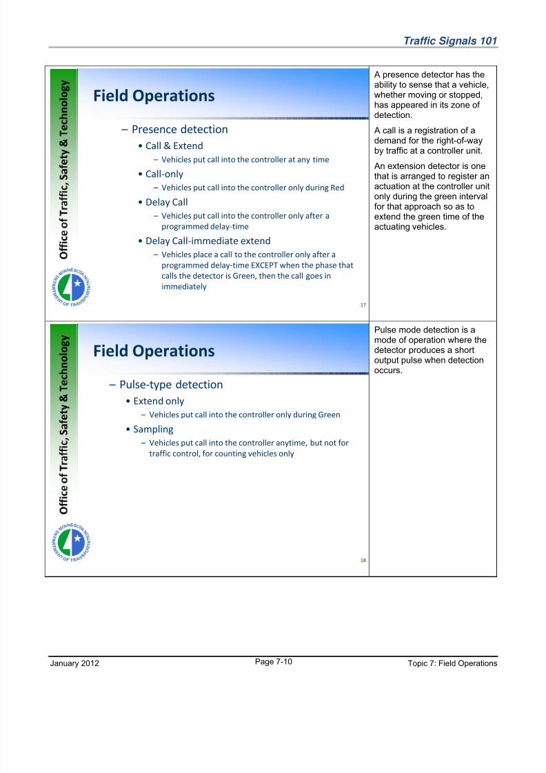
Field Operations
– Presence detection
• Call & Extend
– Vehicles put call into the controller at any time
• Call-only
– Vehicles put call into the controller only during Red
• Delay Call
– Vehicles put call into the controller only after a
programmed delay-time
• Delay Call-immediate extend
– Vehicles place a call to the controller only after a
programmed delay-time EXCEPT when the phase that
calls the detector is Green, then the call goes in
immediately
17
A presence detector has theability to sense that a vehicle,whether moving or stopped,has appeared in its zone of detection.
A call is a registration of ademand for the right-of-wayby traffic at a controller unit.
An extension detector is onethat is arranged to register anactuation at the controller unitonly during the green intervalfor that approach so as toextend the green time of theactuating vehicles.
Field Operations
– Pulse-type detection
• Extend only
– Vehicles put call into the controller only during Green
• Sampling
– Vehicles put call into the controller anytime, but not for
traffic control, for counting vehicles only
18
Pulse mode detection is amode of operation where thedetector produces a shortoutput pulse when detectionoccurs.

8/2/2019 Traffic Signal Field Operations
http://slidepdf.com/reader/full/traffic-signal-field-operations 11/40
Traffic Signals 101
January 2012 Topic 7: Field Operations Page 7-11
Field Operations
– Emergency Vehicle Preemption (EVP)
Detection
• Optical
– Strobe light pulsing at very specific frequency
– Can have digital information encoded on the pulsing
light
• Sonic
– Actually “hears” sirens approaching using directional
microphones
• NOTE!!! about EVP
– EVP has priority over normal traffic operation
19
An EVP detector is a devicethat preempts a traffic signalcontroller. See topic 12 for further details.
Field Operations
– Types of Detectors
• Loop
• Micro-loops
• Magnetometer
• Microwave
• Ultrasonic
• Video
20
A loop detector is the mostcommon detector type. It is aloop of wire imbedded in thepavement carrying a smallelectrical current. When alarge mass of metal passesover the loop, it senses achange in inductance of itsinductive loop sensor by thepassage or presence of avehicle near the sensor.
A magnetometer measuresthe difference in the level of the earth's magnetic forcescaused by the passage or presence of a vehicle near itssensor.
A microwave radar detector isa detector that is capable of sensing the passage of a
vehicle through its field of emitted microwave energy.
An ultrasonic detector is capable of sensing the passage or presence of a vehicle through its field of emittedultrasonic energy.
A video detector responds the video image or changes in the video image of a vehicle.
8/2/2019 Traffic Signal Field Operations
http://slidepdf.com/reader/full/traffic-signal-field-operations 12/40
Traffic Signals 101
January 2012 Topic 7: Field Operations Page 7-12
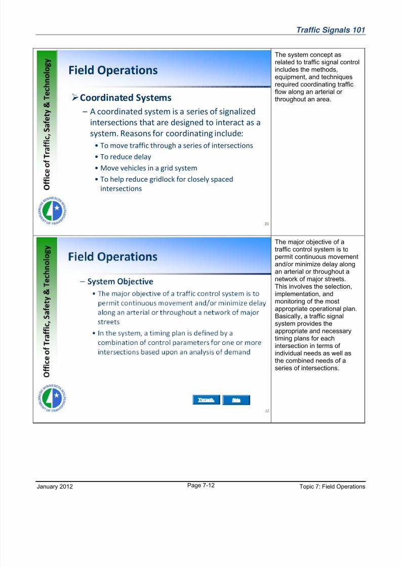
Coordinated Systems – A coordinated system is a series of signalized
intersections that are designed to interact as a
system. Reasons for coordinating include:
• To move traffic through a series of intersections
• To reduce delay
• Move vehicles in a grid system
• To help reduce gridlock for closely spaced
intersections
21
Field Operations
The system concept asrelated to traffic signal controlincludes the methods,equipment, and techniquesrequired coordinating trafficflow along an arterial or
throughout an area.
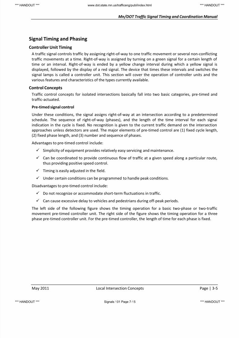
The major objective of atraffic control system is topermit continuous movementand/or minimize delay alongan arterial or throughout anetwork of major streets.This involves the selection,implementation, andmonitoring of the mostappropriate operational plan.Basically, a traffic signalsystem provides theappropriate and necessarytiming plans for eachintersection in terms of individual needs as well asthe combined needs of aseries of intersections.

8/2/2019 Traffic Signal Field Operations
http://slidepdf.com/reader/full/traffic-signal-field-operations 13/40
Traffic Signals 101
January 2012 Topic 7: Field Operations Page 7-13
– Types of Traffic Signal Control Systems
• Time of Day (TOD) Time Based System.
– Non-interconnected System. The offset relationship is
maintained by relying on the clocks in the local controllers
– Interconnected System. Local intersections are physically
interconnected to ensure coordinated operation
• Traffic Responsive System. Volume levels determine
which of a number of available cycle lengths is
selected, and volume differential determines offset
(i.e., inbound, outbound, or average)
24
Field Operations

8/2/2019 Traffic Signal Field Operations
http://slidepdf.com/reader/full/traffic-signal-field-operations 14/40
Traffic Signals 101
January 2012 Topic 7: Field Operations Page 7-14
Handout
Excerpts from the Traffic Signal Timing and Coordination Manual
For the latest version of this manual, please visit:
www.dot.state.mn.us/trafficeng/publ/index.html
8/2/2019 Traffic Signal Field Operations
http://slidepdf.com/reader/full/traffic-signal-field-operations 15/40
Mn/DOT Traffic Signal Timing and Coordination Manual
May 2011 Local Intersection Concepts Page | 3-5
Signal Timing and Phasing
Controller Unit Timing
A traffic signal controls traffic by assigning right-of-way to one traffic movement or several non-conflicting
traffic movements at a time. Right-of-way is assigned by turning on a green signal for a certain length of time or an interval. Right-of-way is ended by a yellow change interval during which a yellow signal is
displayed, followed by the display of a red signal. The device that times these intervals and switches the
signal lamps is called a controller unit. This section will cover the operation of controller units and the
various features and characteristics of the types currently available.
Control Concepts
Traffic control concepts for isolated intersections basically fall into two basic categories, pre-timed and
traffic-actuated.
Pre-timed signal control
Under these conditions, the signal assigns right-of-way at an intersection according to a predetermined
schedule. The sequence of right-of-way (phases), and the length of the time interval for each signal
indication in the cycle is fixed. No recognition is given to the current traffic demand on the intersection
approaches unless detectors are used. The major elements of pre-timed control are (1) fixed cycle length,
(2) fixed phase length, and (3) number and sequence of phases.
Advantages to pre-timed control include:
Simplicity of equipment provides relatively easy servicing and maintenance.
Can be coordinated to provide continuous flow of traffic at a given speed along a particular route,
thus providing positive speed control.
Timing is easily adjusted in the field.
Under certain conditions can be programmed to handle peak conditions.
Disadvantages to pre-timed control include:
Do not recognize or accommodate short-term fluctuations in traffic.
Can cause excessive delay to vehicles and pedestrians during off-peak periods.
The left side of the following figure shows the timing operation for a basic two-phase or two-traffic
movement pre-timed controller unit. The right side of the figure shows the timing operation for a three
phase pre-timed controller unit. For the pre-timed controller, the length of time for each phase is fixed.
*** HANDOUT *** www.dot.state.mn.us/trafficeng/publ/index.html *** HANDOUT **
*** HANDOUT *** Signals 101 Page 7-15 *** HANDOUT **

8/2/2019 Traffic Signal Field Operations
http://slidepdf.com/reader/full/traffic-signal-field-operations 16/40
Mn/DOT Traffic Signal Timing and Coordination Manual
Page | 3-6 Local Intersection Concepts May 2011
Exhibit 3-1 Basic Two-Phase Pre-timed Signal Operation
Traffic-actuated signal control
Traffic-actuated control attempts to adjust green time continuously, and, in some cases, the sequence of
phasing. These adjustments occur in accordance with real-time measures of traffic demand obtained from
vehicle detectors placed on one or more of the approaches to the intersection. The full range of actuated
control capabilities depends on the type of equipment employed and the operational requirements.
Advantages to actuated signals include:
Usually reduce delay (if properly timed).
Adaptable to short-term fluctuations in traffic flow.
Usually increase capacity (by continually reapportioning green time).
Provide continuous operation under low volume conditions as an added safety feature, when pre-
timed signals may be put on flashing operation to prevent excessive delay.
Especially effective at multiple phase intersections.
Disadvantages to actuated control include:
The cost of an actuated installation is higher than the cost of a pre-timed installation.
Actuated controllers and detectors are much more complicated than pre-timed signal controllers,
increasing maintenance and inspection skill requirements and costs.
Detectors are costly to install and require careful inspection and maintenance to ensure proper
operations.
Traffic actuated signal control can further be broken into the following categories:Semi-Actuated Control . In semi-actuated control, the major movement receives green unless there is a
conflicting call on a minor movement phase. The minor phases include any protected left-turn phases or
side street through phases. Detectors are needed for each minor movement. Detectors may be used on
the major movement if dilemma zone protection is desired.
In semi-actuated coordinated systems (referred to as Actuated Coordinated in Synchro), the major
movement is the “sync” phase. Minor movement phases are served only after the sync phase yield point
and are terminated on or before their respective force off points. These points occur at the same point in
GREEN YEL. RED
RED GREEN YEL.
PHASE 1
PHASE 2
PHASE 1 SPLIT PHASE 2 SPLIT
N
CYCLE LENGTH
PHASE 1 PHASE 2
GREEN YEL. RED
RED GREEN YEL.
PHASE 1
PHASE 2
PHASE 1 SPLIT PHASE 3 SPLIT
CYCLE LENGTH
YEL.
PHASE 2 SPLIT
GREENRED
RED
PHASE 3
PHASE 1 PHASE 2 PHASE 3
*** HANDOUT *** www.dot.state.mn.us/trafficeng/publ/index.html *** HANDOUT **
*** HANDOUT *** Signals 101 Page 7-16 *** HANDOUT **

8/2/2019 Traffic Signal Field Operations
http://slidepdf.com/reader/full/traffic-signal-field-operations 17/40
Mn/DOT Traffic Signal Timing and Coordination Manual
May 2011 Local Intersection Concepts Page | 3-7
time during the background signal cycle and ensure that the major road phase will be coordinated with
adjacent signal controllers.
In semi-actuated non-coordinated systems, the major movement phase is placed on minimum (or
maximum) recall. The major movement rests in green until a conflicting call is placed. The conflicting phase
is serviced as soon as a gap-out or max-out occurs on the major phase. Immediately after the yellow is
presented to the major phase, a call is placed by the controller for the major phase, regardless of whetheror not a major phase vehicle is present.
Full Actuated Control . In full actuated control, all signal phases are actuated and all signalized movements
require detection. Generally used at isolated intersections; however, can also be used at high-demand
intersections in coordinated systems.
Volume-density operation can be considered to be a more advanced form of full-actuated control. It has
the ability to calculate the duration of minimum green based on actual demand (calls on red) and the
ability to reduce the maximum allowable time between calls from passage time down to minimum gap.
Reducing the allowable time between calls below the passage time will improve efficiency by being better
able to detect the end of queued flow.
Traffic Signal PhasingA traffic signal phase, or split, is the part of the cycle given to an individual movement, or combination of
non-conflicting movements during one or more intervals. An interval is a portion of the cycle during which
the signal indications do not change.
The predetermined order of phases is the sequence of operation. This order is fixed in a pre-timed
controller, and under certain circumstances, may be variable with an actuated controller.
Consider the following figure for an example two-phase (single ring) signal with pedestrian timing.
*** HANDOUT *** www.dot.state.mn.us/trafficeng/publ/index.html *** HANDOUT **
*** HANDOUT *** Signals 101 Page 7-17 *** HANDOUT **

8/2/2019 Traffic Signal Field Operations
http://slidepdf.com/reader/full/traffic-signal-field-operations 18/40
Mn/DOT Traffic Signal Timing and Coordination Manual
Page | 3-8 Local Intersection Concepts May 2011
Exhibit 3-2 Traffic Signal Phasing
In the figure, there are eight intervals where the signal indications do not change. Notice that intervals 4
and 8 are all red periods (interval 4 is the phase 1 all red and interval 8 is the phase 2 all red). The phase 1
split is made up of intervals 1 through 4 and the phase 2 split is made up of intervals 5 through 8. The sum
of split 1 and 2 is the cycle length.
Ring and Barrier Structure
Ring
A ring is a term that is used to describe a series of conflicting phases that occur in an established order. A
ring may be a single ring, dual ring, or multi-ring and is described in detail below. A good understanding of
the ring structure is a good way to understand the operation of multiphase controllers.
Barrier
A barrier (compatibility line) is a reference point in the preferred sequence of a multi-ring controller unit at
which all rings are interlocked. Barriers assure there will be no concurrent selection and timing of
conflicting phases for traffic movements in different rings. All rings cross the barrier simultaneously to
select and time phases on the other side.
Phase Numbers
Phase numbers are the labels assigned to the individual movements around the intersection. For an eight
phase dual ring controller (see definition of dual ring), it is common to assign the main street through
GREEN YEL. RED
RED GREEN YEL.
PHASE 1
PHASE 2
WALK FDW DON'T WALK
WALK FDWDON'T WALK
INTERVAL 1 2 3 4 5 6 7 8
PHASE 1 PED.
PHASE 2 PED.
PHASE 1 SPLIT PHASE 2 SPLITSPLIT
PHASE 1 PHASE 2
N
CYCLE LENGTH
Sequence of Operation
*** HANDOUT *** www.dot.state.mn.us/trafficeng/publ/index.html *** HANDOUT **
*** HANDOUT *** Signals 101 Page 7-18 *** HANDOUT **

8/2/2019 Traffic Signal Field Operations
http://slidepdf.com/reader/full/traffic-signal-field-operations 19/40
Mn/DOT Traffic Signal Timing and Coordination Manual
May 2011 Local Intersection Concepts Page | 3-9
movements as phases 2 and 6. Also, it is common to use odd numbers for left turn signals and the even
numbers for through signals. A rule of thumb is that the sum of the through movement and the adjacent
left turn is equal to seven or eleven.
The figure below shows a typical phase numbering scheme for an east/west arterial and a north/south
arterial.
Exhibit 3-3 Common Phase Numbering Scheme
Dual Ring Control
By contrast to the pre-timed controller unit, the traffic actuated controller usually employs a “dual ring
concurrent” timing process. The NEMA concept is illustrated in the figure below.
Exhibit 3-4 Dual Ring Control
The dual-ring controller uses a maximum of eight phase modules, each of which controls a single traffic
signal face with red, yellow and green display. The eight phases are required to accommodate the eight
movements (four through and four left turns) at the intersection. Phases 1 through 4 are included in ring 1,
and phases 5 through 8 are included in ring 2. The two rings operate independently, except that their
control must cross the “barrier” at the same time.
If the movements to be controlled by these eight phases are assigned properly, the controller will operate
without giving the right-of-way simultaneously to conflicting movements. All of the movements from one
street (usually the major street) must be assigned to the left side of the barrier. Similarly, all movements
from the other street must be assigned to the right side.
On both sides of the barrier there are four movements (two through and two left). Each of the four may
proceed without conflict with two of the other three. So if the left turn in any given direction is placed in
DUAL RING STRUCTURE
5 6
3 41 2
7 8
RING A
RING B
BARRIER 1
(LEFT SIDE)
BARRIER 2
(RIGHT SIDE)
*** HANDOUT *** www.dot.state.mn.us/trafficeng/publ/index.html *** HANDOUT **
*** HANDOUT *** Signals 101 Page 7-19 *** HANDOUT **

8/2/2019 Traffic Signal Field Operations
http://slidepdf.com/reader/full/traffic-signal-field-operations 20/40
Mn/DOT Traffic Signal Timing and Coordination Manual
Page | 3-10 Local Intersection Concepts May 2011
ring 1 along with its opposing through movement, and the remaining two movements are placed in ring 2,
it will be possible for either movement in ring 1 to be displayed simultaneously with either movement in
ring 2 without conflict.
The dual-ring concurrent operation can be shown to maximize the operating efficiency at an intersection
by eliminating the “slack” time on each cycle (i.e., control will follow one or the other of the two path s
shown).
Modern controllers offer more flexibility in assigning traffic signal phases in order to control many complex
or unique situations. TS2 controllers include four timing rings and up to sixteen vehicle phases and sixteen
pedestrian phases. Each phase can be assigned to any ring. In addition, there are up to sixteen overlap
assignments.
Single Ring (Sequential Phases)
Sometimes it is desirable to use a single ring and have the phases operate one at a time sequentially. Each
phase is individually timed and can be skipped if there is no demand for it. This is called sequential or
exclusive phasing. When using sequential phases on the left side of the barrier, phases 1-2-5-6 show in
order. When using sequential phases on the right side of the barrier, phases 3-4-7-8 show in order.
The figure below is an example of a controller using Sequential phases. North and South traffic use splitphasing, East and West share a phase.
Exhibit 3-5 Sequential Phasing
Phasing Parameters
Some of the basic principles of timing the green interval in a traffic actuated controller unit are as follows:
There must be a minimum green time so that a stopped vehicle that receives a green signal has
enough time to get started and partially across the intersection before the yellow signal appears.
This time is termed the initial portion of the green interval.
Each following vehicle requires green time. This is called passage time, vehicle extension, or gap.
Gap refers to the distance between vehicles as well as the time between vehicles. There must be a maximum time that the green interval can be extended if opposing cars are waiting
- this is called extension limit or maximum.
A timing diagram for one traffic actuated phase is shown in the figure that follows. The other phase
or phases operate in the same manner.
1 2 5 6 3 4
7 8
RING A
BARRIER 1
(LEFT SIDE)
BARRIER 2
(RIGHT SIDE)
*** HANDOUT *** www.dot.state.mn.us/trafficeng/publ/index.html *** HANDOUT **
*** HANDOUT *** Signals 101 Page 7-20 *** HANDOUT **

8/2/2019 Traffic Signal Field Operations
http://slidepdf.com/reader/full/traffic-signal-field-operations 21/40
Mn/DOT Traffic Signal Timing and Coordination Manual
May 2011 Local Intersection Concepts Page | 3-11
The number of “presets” is the number of timing adjustments in the extensible portion. Each
detector actuation starts the unit extension timing again. With no opposing calls the controller rests.
Unit extensions continue being timed, but with no effect on the green interval.
However, once an actuation is received from an opposing phase, unit extension is used to expedite
servicing that phase as follows: if the time between actuations is greater than the preset unit
extension or gap the extensible portion will be ended, the yellow change interval will appear and thenext phase in sequence with demand will receive the right-of-way. This is called termination by gap
or gap-out.
An actuation from another phase received in any portion of the green interval also starts another
timing circuit. This is called the extension limit or maximum green. Even if actuations are close
enough in time to prevent gap termination, the maximum limit will terminate the green interval
when the preset maximum expires. This is called termination by maximum green or max-out.
Exhibit 3-6 Traffic Actuated Phase Timing Diagram
Minimum Green
The Minimum Green Interval is the shortest green time of a phase. If a time setting control is designated as
"minimum green," the green time shall be not less than that setting. For Mn/DOT practice on minimum
green (minimum initial) times, refer to page 4-7.
Initial Intervals
There are three types of initial intervals as follows:
Extensible initial
*** HANDOUT *** www.dot.state.mn.us/trafficeng/publ/index.html *** HANDOUT **
*** HANDOUT *** Signals 101 Page 7-21 *** HANDOUT **

8/2/2019 Traffic Signal Field Operations
http://slidepdf.com/reader/full/traffic-signal-field-operations 22/40
Mn/DOT Traffic Signal Timing and Coordination Manual
Page | 3-12 Local Intersection Concepts May 2011
Added initial
Computed initial
Extensible initial is the method of calculating the variable initial period commonly used in field practice.
This method adds the time specified as “seconds per actuation” to the minimum initial (green) for each
vehicle actuation received by a phase during the yellow and/or red signal (depending on red and yellow
lock) up to a maximum initial time. This method is common in both 170 and NEMA controllers.
Added initial is similar to extensible initial with the exception that the “seconds per actuation” calculati on
does not begin until a user specified number of vehicles actuations have occurred. The added initial option
is generally used when long minimum green times are specified.
Computed initial calculates the amount of time given to each vehicle actuation (computed seconds per
actuation) during the red signal display of the phase based on the following formula:
(Maximum initial interval time) (number of actuations that can be serviced during the minimum initial
interval) x (number or recorded actuations). The total time allowed for the computed initial interval is
limited by both the minimum green and maximum initial interval.
Passage Time
Passage Time (also referred to as vehicle extension or gap time) is the time that the phase will be extended
for each actuation. Passage time is typically set as the time it takes to travel from the vehicle detector to
the stop line at the travel speed of the roadway for pulse loops or the average acceptable headway
between vehicles for presence loops located close to the stop line. Therefore, the vehicle extension is
related to the minimum and maximum gap. For Mn/DOT practice on passage time refer to page 4-13.
Maximum Green
Depending on the type and manufacturer of the controller being simulated, there can be two methods for
calculating the maximum amount of green time allowed per phase. Method 1 or maximum green, allows
the user to input the maximum amount of green time a phase will be allowed to be active, (i.e. display
green.) The max. timer in the controller begins its countdown at the receipt of a conflicting vehicle orpedestrian call, generally the beginning of phase green and includes any minimum green or variable initial
period.
Method 2, maximum green extension, is the amount of time a phase will be allowed service after the
minimum green and variable initial have timed out. While some controller manufacturers still allow
maximum green extension, it is more commonly found in older isolated NEMA and Type 170 controllers.
Assuming that vehicle headways remain less than the vehicle extension time during the green signal
display of the phase, Method 1 will always produce the same timing value. However, in Method 2 the total
green time is not only dependent on vehicle headways during the phase green but also on the number of
vehicles that arrive during the red display for the calculation of variable initial. Therefore, total green time
for Method 2 can vary from cycle to cycle irrelevant of vehicle headways.
If the controller is operating within a coordinated system the maximum green time specified in the
controller may not be appropriate for the cycle/split combination selected by the master controller. In this
case the phase can max-out early without ever reaching the force-off point (the end of the assigned phase
split) for the phase.
Note: In certain manufacturers’ controllers, there will be a timing function called “MAX EXT.” This is not
the same as maximum extension green but the number of seconds used to extend the maximum green
value when “MAX 3” is active.
*** HANDOUT *** www.dot.state.mn.us/trafficeng/publ/index.html *** HANDOUT **
*** HANDOUT *** Signals 101 Page 7-22 *** HANDOUT **

8/2/2019 Traffic Signal Field Operations
http://slidepdf.com/reader/full/traffic-signal-field-operations 23/40
Mn/DOT Traffic Signal Timing and Coordination Manual
May 2011 Local Intersection Concepts Page | 3-13
For Mn/DOT practice on maximum green times, refer to page 4-15.
Pedestrian Phasing
Because pedestrians move at a slower speed than vehicles, they require different treatment of the green
interval. A pedestrian actuation, therefore, results in more green time than would be allowed for a vehicle:
a “Walk” interval followed by a flashing “Don’t Walk” pedestrian clearance. In the absences of opposing
calls, succeeding pedestrian actuations will recycle the pedestrian indications.
Pedestrian intervals result in a green interval for the parallel vehicle phase or phases. The figure on
the page 3-11 shows the timing diagram for pedestrian operation.
It is also possible to have an exclusive pedestrian phase. That is, no vehicle green intervals will occur.
All pedestrian signals at an intersection could be controlled by this phase.
Red Vehicle Clearance
Red clearances (ALL RED) is the safety clearance interval at the end of a phase that displays red for all
traffic movements. For Mn/DOT practice on red clearance intervals see page 4-18.
Recall
Normally a controller unit will, in the absence of actuation, rest on the last phase serviced. By means of a
recall switch the controller unit can be forced to return to a particular phase’s green interval, even with no
demand.
Every phase has the capability of operation with the following types of recall:
Minimum Recall . When active and in the absence of a vehicle call on the phase, a temporary call to
service the minimum initial time will be placed on the phase. If a vehicle call is received prior to the
phase being serviced the temporary call will be removed. Once the phase is serviced it can be
extended based on normal vehicle demand.
Maximum Recall. With the maximum vehicle recall active a constant vehicle call will be placed on
the phase. This constant call will force the controller to time the maximum green. Maximum recall isgenerally used to call a phase when local detection is not present or inoperative.
Pedestrian Recall. This feature provides vehicle green and pedestrian walk and clearance intervals.
After that, normal green timing is in effect except that pedestrian calls will not recycle pedestrian
intervals until opposing phases are serviced.
In addition, a phase has a vehicle call placed on it if it is terminated with some passage time
remaining. This can happen with termination by maximum.
If all of the active phases of a controller unit are placed on recall the controller unit will operate in a
pre-timed mode. It should be added that unless the detectors are disconnected from a phase, that
phase’s green interval could be extended beyond the preset minimum if the recall is to minimum.
Volume Density Control
Even more sophisticated operation is possible with the volume density traffic actuated controller unit. In
addition to the features discussed above, volume density provides two means of modifying the basic
timing intervals. These are:
Variable initial is a means of extending the initial portion of the green interval. This is done on the
basis of the number of actuations above a preset number while the phase is displaying yellow or
red. This extended initial provides additional green time for a queue of vehicles waiting, when the
*** HANDOUT *** www.dot.state.mn.us/trafficeng/publ/index.html *** HANDOUT **
*** HANDOUT *** Signals 101 Page 7-23 *** HANDOUT **

8/2/2019 Traffic Signal Field Operations
http://slidepdf.com/reader/full/traffic-signal-field-operations 24/40
Mn/DOT Traffic Signal Timing and Coordination Manual
Page | 3-20 Local Intersection Concepts May 2011
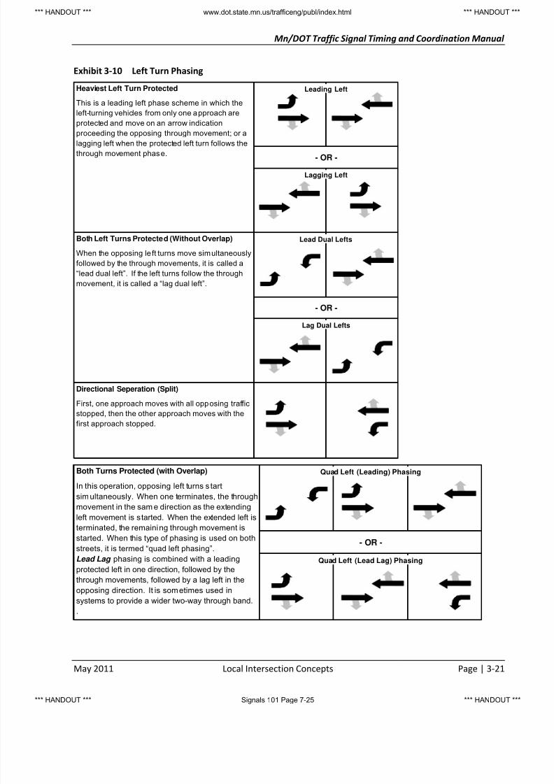
Left Turn Phasing
A critical element to the operation of a traffic signal is the determination of the appropriate phasing
scheme. At signalized intersections where traffic volumes are heavy or speeds are high, vehicles
attempting to turn left across opposing traffic may constitute significant safety and capacity problems.
Based on this, there are additional considerations for determining the left turn phasing alternative. These
include:
Heaviest Left Turn Protected - This is a leading left phase scheme in which the left-turning vehicles
from only one approach are protected and move on an arrow indication proceeding the opposing
through movement; or a lagging left when the protected left turn follows the through movement
phase.
Both Left Turns Protected (Without Overlap) - When the opposing left turns move simultaneously
followed by the through movements, it is called a “lead dual left”. If the left turns follow the through
movement, it is called a “lag dual left”.
Both Left Turns Protected (With Overlap) - In this operation, opposing left turns start simultaneously.
When one terminates, the through movement in the same direction as the extending left movement
is started. When the extended left is terminated, the remaining through movement is started. Whenthis type of phasing is used on both streets, it is termed “quad left phasing”.
Lead Lag - This phasing is combined with a leading protected left in one direction, followed by the
through movements, followed by a lag left in the opposing direction. It is sometimes used in systems
to provide a wider two-way through band.
Directional Separation (Split) - First, one approach moves with all opposing traffic stopped, then the
other approach moves with the first approach stopped.
The figure on the following page shows the above basic left turn phasing schemes.
Whether or not separate left turn phasing should be provided is a decision that must be based on
engineering analysis. This analysis may involve serious trade-offs between safety, capacity, and delay
considerations.
Separation of left turns and opposing traffic may reduce accidents that result from conflicts
between these movements, and may increase left turn capacity. However, through traffic capacity
may be reduced.
Left turn phasing may reduce peak period delay for left turners, but may increase overall
intersection delay. Off-peak left turn delay may also increase.
*** HANDOUT *** www.dot.state.mn.us/trafficeng/publ/index.html *** HANDOUT **
*** HANDOUT *** Signals 101 Page 7-24 *** HANDOUT **
8/2/2019 Traffic Signal Field Operations
http://slidepdf.com/reader/full/traffic-signal-field-operations 25/40
Mn/DOT Traffic Signal Timing and Coordination Manual
May 2011 Local Intersection Concepts Page | 3-21
Exhibit 3-10 Left Turn Phasing
Heaviest Left Turn Protected
This is a leading left phase scheme in which the
left-turning vehicles from only one approach are
protected and move on an arrow indication
proceeding the opposing through movement; or alagging left when the protected left turn follows the
through movement phase.
Both Left Turns Protected (Without Overlap)
When the opposing le ft turns move simultaneously
followed by the through movements, it is called a
“lead dual left”. If the left turns follow the throughmovement, it is called a “lag dual left”.
Directional Seperation (Split)
First, one approach moves with all opposing traffic
stopped, then the other approach moves with thefirst approach stopped.
- OR -
Leading Left
Lagging Left
- OR -
Lag Dual Lefts
Lead Dual Lefts
Both Turns Protected (with Overlap)
In this operation, opposing left turns s tart
simultaneously. When one terminates, the through
movement in the sam e direction as the extending
left movement is started. When the extended left is
terminated, the remaining through movement is
started. When this type of phasing is used on both
streets, it is termed “quad left phasing”.Lead Lag phasing is combined with a leading
protected left in one direction, followed by the
through movements, followed by a lag left in the
opposing direction. It is sometimes used in
systems to provide a wider two-way through band.
.
- OR -
Quad Left (Leading) Phasing
Quad Left (Lead Lag) Phasing
*** HANDOUT *** www.dot.state.mn.us/trafficeng/publ/index.html *** HANDOUT **
*** HANDOUT *** Signals 101 Page 7-25 *** HANDOUT **

8/2/2019 Traffic Signal Field Operations
http://slidepdf.com/reader/full/traffic-signal-field-operations 26/40
Mn/DOT Traffic Signal Timing and Coordination Manual
Page | 3-24 Local Intersection Concepts May 2011
Flashing Yellow Arrow Display
The Flashing Yellow Arrow (FYA) head is a signal that uses a flashing yellow arrow
indication for permissive left turns instead of using a green ball. A 7-year national study
determined that the 4-section FYA signal head with a red arrow on top, followed by a
steady yellow arrow, a flashing yellow arrow, and then a green arrow on the bottom wasthe best and safest type of left-turn signal head based on driver confirmation and field
implementation studies.
The FYA head is now the recommended left turn head in the Federal 2009 Manual of
Uniform Traffic Control Devices (MUTCD). This version of the MUTCD includes language on
the use of the flashing yellow arrow for permitted left turns that states:
“Vehicular traffic, on an approach to an intersection, facing a flashing YELLOW ARROW signal
indication, displayed alone or in combination with another signal indication, is permitted to
cautiously enter the intersection only to make the movement indicated by such arrow, or other such
movement as is permitted by other signal indications displayed at the same time.
Such vehicular traffic, including vehicles turning right or left or making a U-turn, shall yield the right-of-way to:
a) Pedestrians lawfully within an associated crosswalk, and
b) Other vehicles lawfully within the intersection.
In addition, vehicular traffic turning left or making a U-turn to the left shall yield the right-of-way to
other vehicles approaching from the opposite direction so closely as to constitute an immediate
hazard during the time when such turning vehicle is moving across or within the intersection.”
At the time of publication of this Manual, Mn/DOT is updating the Minnesota MUTCD. It is anticipated that
the above language from the Federal MUTCD will be found in the MN MUTCD.
Mn/DOT does encourage the use of FYA whenever appropriate. Additional details on the FYA can be found
by visiting:
http://www.dot.state.mn.us/trafficeng/signals/flashingyellowarrow.html
http://mutcd.fhwa.dot.gov/resources/interim_approval/ia_10_flashyellarrow.htm
http://www.fhwa.dot.gov/publications/research/safety/09036/index.cfm
Flashing Yellow Arrow and the Left Turn Trap
Exhibit 3-11 illustrated a left turn trap with traditional lead/lag phasing (i.e., a green ball indication is used
for the permitted left turns). Using a FYA indication can eliminate the trap condition illustrated in this
Exhibit.
Once again, consider the EBL vehicle in this Exhibit. During interval 1, the EBL receives a green arrow and
proceeds under the protected movement. During interval 2, the EBL shows the flashing yellow arrowindication and the movement operates as a permissive movement. In interval 3, the EBL remains a
flashing yellow arrow indication instead of turning red. The EBL FYA actually operates as an overlap to
phase 6. Therefore, the EBL and opposing WBT terminate at the same time as expected by the driver.
Exhibit 3-12 illustrates the signal operation of the FYA even under the “soft-trap” condition and how this
can be eliminated.
*** HANDOUT *** www.dot.state.mn.us/trafficeng/publ/index.html *** HANDOUT **
*** HANDOUT *** Signals 101 Page 7-26 *** HANDOUT **

8/2/2019 Traffic Signal Field Operations
http://slidepdf.com/reader/full/traffic-signal-field-operations 27/40
Mn/DOT Traffic Signal Timing and Coordination Manual
May 2011 Local Intersection Concepts Page | 3-25
Exhibit 3-12 FYA to Eliminate Left Turn Trap
Interval 1: During this interval, normal
leading protected and opposing left
turn phases operate. This is the typical
operation even with a traditional 5-
section signal indication.
At the end of this interval, phase 1
clears the intersection with a solid
yellow arrow.
Interval 2: During this interval phase 2
begins green as phase 5 continuesgreen in normal operation. The
opposing left turn is operated as a FYA.
In a traditional 5-section operation, the
opposing left turn would be red.
Interval 3: In this interval, phase 2 and
6 throughs receive a green ball
indication. The opposing lefts are
operated as an FYA overlap with the
opposing through. This will ensure that
the left turn clears (turns yellow) and
then red with the opposing through,
thus eliminating the left turn trap.
5
1
2
5
2 The WBL is operated as
an overlap with
opposing phase 2
6The EBL is operated as
an overlap with the
opposing phase 6
2
2
6
*** HANDOUT *** www.dot.state.mn.us/trafficeng/publ/index.html *** HANDOUT **
*** HANDOUT *** Signals 101 Page 7-27 *** HANDOUT **

8/2/2019 Traffic Signal Field Operations
http://slidepdf.com/reader/full/traffic-signal-field-operations 28/40
Mn/DOT Traffic Signal Timing and Coordination Manual
Page | 3-26 Local Intersection Concepts May 2011
Minnesota Flashing Yellow Arrow
The section on “Flashing Yellow Arrow Display” starting on
page 3-24 discusses the FYA from a national and Federal
MUTCD perspective. The following sections discuss the use of
the FYA within Minnesota.
Variable vs. Fixed Phasing Operation Signal Heads
Traditionally, the operation of the left turn signal was
considered Fixed. That is, if a protected left turn head was
installed, then this signal would operate in protected
operation for the entire day. It may be that a protected left is
desirable for a specific time of day (i.e., heavy opposing flow
is the reason for the protected operation), but this may
“penalize” the other twenty-three hours of the day that do not require protected-only operation. One
advantage to the FYA signal indication is that it can change the mode of operation on a time of day (TOD)
basis. In summary:
The FYA head is a “variable phasing operation” head that can operate with either protected,protected/permissive, or permissive phasing operation by time-of-day settings.
Standard 3-section protected and 3-section permissive heads are “fixed phasing operation” heads
that can only operate in one phasing operation 24 hours a day.
Given that the FYA head can operate protected 24 hours a day, if desired, the standard 3-section
protected head will soon become obsolete as there is no reason to install a 3-section protected head
and not have the ability to change the phasing operation in the future.
Standard 5-section heads are “flexible phasing operation” heads, but only with either
protected/permissive or permissive operation by time-of-day settings.
Use of the Flashing Yellow Arrow Signal Head
New Signal Design
All agencies should consider using a FYA in their design of new signals with exclusive left turn lanes.
However, it’s still acceptable to use a 3-section protected or 5-section protected/permissive head for new
signal installations. Designs should conform to the Federal and MN MUTCDs. The 2009 Federal MUTCD no
longer allows a green circular permitted signal indication centered over an exclusive left turn lane (see the
Federal MUTCD Section 4D.13).
Even if a left turn movement may never have a high enough left-turn volume to run protected/permissive,
consider using a FYA head for exclusive left turn lanes as it gives flexibility in case volumes increase in the
future, and it also gives a clearer message to left turning vehicles that they must yield to opposing traffic
when turning left.
The incremental increase in cost of a 4-section FYA signal head is insignificant in the overall cost of the new
signal. In fact, the 4-section signal head may be less expensive than the 5-section protected/permissive
signal head.
Retrofit Signal Design
An existing signal with exclusive left turn lanes may be retrofitted with FYA operation. Consideration
should take into account the type of cabinet, controller, loop detection, and mast arm locations when
The discussions in this section
“Minnesota Flashing Yellow Arrow”
are current at the time of printing
this publication. However, the items
mentioned are anticipated to be
continually changing. Please be sure
to constently check the Mn/DOT
website for updates (See Mn/DOT
Website and Contacts on page 3-34).
*** HANDOUT *** www.dot.state.mn.us/trafficeng/publ/index.html *** HANDOUT **
*** HANDOUT *** Signals 101 Page 7-28 *** HANDOUT **

8/2/2019 Traffic Signal Field Operations
http://slidepdf.com/reader/full/traffic-signal-field-operations 29/40
Mn/DOT Traffic Signal Timing and Coordination Manual
May 2011 Local Intersection Concepts Page | 3-27
retrofitting a signal for FYA. This issue is currently under development by Mn/DOT and more information
is forthcoming.
When Not to Operate a FYA Head
Under certain situations, the FYA indication should not be used as noted below, even if the 4-section FYA
head is in place.
A. Opposing Left Turn Paths Conflict
Road design will be responsible for noting on signal design plan that opposing left turns conflict by
running AutoTurn and cannot be allowed to turn at the same time.
B. Very Limited Sight Distance
Sight distance is so limited that a left turn cannot be made safely even under very low volume
conditions
C. Shared Left/Through Lane(s)
The concept of using a Flashing Yellow Arrow head on approaches with shared left-turn/through
lanes is under development, but is currently only recommended for experimental use and more
information is forthcoming (see the section “Mn/DOT Website and Contacts” on page 3-34 if
considering this type of operation).
In addition, see the sections below regarding FYA use with pre-emption (emergency vehicle and railroad).
Yellow and All-Red Times
Yellow time for clearing the green arrow for leading or lagging left turns will be the same as the current
agency standard for left-turn operation (see page 4-17).
Yellow time for clearing the FYA will be the opposing through yellow time (3.5 to 6.0 sec) as the FYA will be
driven by an overlap with the opposing through phase.
When transitioning from a protected left turn to a permissive left turn in protected/permissive operations,
the all-red time will be 2 seconds with the red arrow being shown.
Permissive Operation When Adjacent through Head is Red
The FYA display will allow for a permissive operation when the adjacent through head is red (see Exhibit
3-12). This was not possible with the 5-section protected/permissive head. This situation could occur if
one left turn movement runs longer than the opposing left turn movement and the shorter left turn will
get the permissive flashing yellow arrow while the opposing left turn is causing the adjacent through head
to still be red.
Adjacent through heads may also be red when lagging lefts are used with protected/permissive operation.
This is also something that wasn’t possible with the 5 -section protected/permissive head as it would cause
a “left-turn trap” (See the discussion on “Left Turn Trapping” on page 3-22). The FYA head doesn’t cause a
left-turn trap because it is an exclusive head for left turning vehicles (see the topic “Flashing Yellow Arrowand the Left Turn Trap” on page 3-24). However, it is a new operation for motorists in that they will be
looking for gaps while yielding on the flashing yellow arrow while the adjacent through head goes yellow
due to the opposing protected/permissive lagging left. The flashing yellow arrow will continue to operate
even though the adjacent head goes red and motorists will need to continue to yield to oncoming traffic.
*** HANDOUT *** www.dot.state.mn.us/trafficeng/publ/index.html *** HANDOUT **
*** HANDOUT *** Signals 101 Page 7-29 *** HANDOUT **

8/2/2019 Traffic Signal Field Operations
http://slidepdf.com/reader/full/traffic-signal-field-operations 30/40
Mn/DOT Traffic Signal Timing and Coordination Manual
May 2011 Local Intersection Timing Page | 4-5
steady DON’T WALK indication, means that a pedestrian shall not enter the roadway in the direction
of the indication.
Walk
The MN MUTCD states, "Under normal conditions, the WALK interval should be at least 4 to 7 seconds in
length so that pedestrians will have adequate opportunity to leave the curb before the clearance interval is
shown." Research indicates that queues (more than 24 people) requiring more than 7 seconds to
discharge occur very rarely and will usually be found only in certain sections of large metropolitan areas.
The minimum WALK interval under low volume (less than 10 pedestrians per cycle) conditions could
possibly be lowered to 4 - 5 seconds but the importance of the inattentiveness factor should be also
weighted in this decision.
Flashing Don’t Walk
NOTE: The information in this section is currently being updated in the Minnesota MUTCD. See the section
Pedestrian Timing (2009 Federal MUTCD) on page 4-7. It is anticipated that the MN MUTCD will adopt the
Federal MUTCD requirements for pedestrian timing.
The duration of the pedestrian clearance time should be sufficient to allow a pedestrian crossing in the
crosswalk who left the curb or shoulder at the end of the WALKING PERSON (symbolizing WALK) signal
indication to travel at a walking speed of 3.5 feet per second to at least the far side of the traveled way or
to a median of sufficient width for pedestrians to wait.
The flashing DON’T WALK interval is determined by the following formula:
flashing DON’T WALK = D/R
D = Distance from the near curb or shoulder to at least the far side of the traveled way or to a
median of greater than 6 feet.
R = Walking rate of 3.5 feet per second assumed walking rate unless special conditions (school
kids, elderly or handicapped) require a slower walking rate.
When determining the distance, consideration should be given to the pedestrian's normal walking path.Pedestrian timing should consider the pedestrian walking to the nearest pedestrian and/or vehicle
indication following a marked or unmarked crosswalk.
On median divided roadways, consideration should be given to providing sufficient time to the pedestrians
to cross both roadways. A pedestrian's goal is to cross the total roadway and does not expect to stop at
the dividing median and wait till the next cycle. If the median is less than 6 feet wide the pedestrian should
be provided sufficient time to cross both roadways as a median less than 6 feet wide is not considered a
safe refuge island.
Normal walking speed is assumed to be 3.5 feet per second. This is as cited in the 2009 Federal MUTCD
and will be the walking speed used in the pending update to the MN MUTCD. In selecting a walking rate,
consideration must be given to the type of pedestrians, volume of pedestrians, intersection location andgeometrics and overall signal operation.
Signal controllers used by Mn/DOT do not time the yellow vehicle indication concurrent with the flashing
DON’T WALK. This is assuming minimum vehicle green time. The steady DON’T WALK is displayed at the
onset of yellow to encourage any pedestrians still in the street to complete the crossing without delay.
Because of this and a MN MUTCD Ruling No. IV-35, Pedestrian Clearance Interval Calculation, the yellow
interval may be included in the pedestrian clearance time (i.e., the pedestrian clearance time is equal to
*** HANDOUT *** www.dot.state.mn.us/trafficeng/publ/index.html *** HANDOUT **
*** HANDOUT *** Signals 101 Page 7-30 *** HANDOUT **

8/2/2019 Traffic Signal Field Operations
http://slidepdf.com/reader/full/traffic-signal-field-operations 31/40
Mn/DOT Traffic Signal Timing and Coordination Manual
Page | 4-6 Local Intersection Timing May 2011
flashing DON’T WALK interval plus the yellow interval) . The flashing DON’T WALK interval could then be
determined by the following formula:
flashing DON’T WALK = (D/R) - Yellow
However, the ruling also states, "Discretion should be used in utilizing the latitude afforded by Section 4E”.
Therefore, as a general practice, this should not be followed unless it is necessary to minimize the
pedestrian timing. By subtracting the yellow interval, pedestrians may receive the steady DON’T WALK
before they reach the far side of the farthest traveled lane. Engineering studies and judgment should be
exercised in determining walking rates, distances and utilizing the yellow interval as part of the pedestrian
clearance interval.
Pedestrian Timing Recommended Practice
At the time of the publication of this manual, the MN MUTCD was being updated. It is anticipated that the
MN MUTCD will follow closely the language as found in the 2009 Federal MUTCD. Pertinent sections of the
Federal MUTCD can be found on page 4-7.
For single roadways, and divided roadway with median island less than 6 feet wide and pedestrian
indications on each side, the pedestrian will be provided time to cross from the near side curb or shoulder
to the far side of the traveled way.
WALK = 7 seconds
(this may be reduced to 4 seconds if it is necessary to minimize pedestrian timing considering the other
factors)
flashing DON'T WALK = (D/R)
(time should not be less than WALK time and the time may be reduced by the yellow interval if it is
necessary to minimize pedestrian timing considering other factors)
D = Distance from the near curb or shoulder to at least the far side of the traveled way.
R = Walking rate of 3.5 feet per second is the assumed walking rate unless special conditions (school
kids, elderly or handicapped) require a slower walking rate.
Divided Roadways
A divided road is one with a median island over 6 feet wide and includes a pedestrian pushbutton in the
median. If a pushbutton is not in the median, the recommended practice above must be used (i.e., the
pedestrian clearance interval must cross them completely from near side curb to far side curb).
Option 1 - Cross to Median Only
(Pedestrian indications present)
The WALK and flashing DON’T WALK should be determined as above. The crossing distance should be
determined by using the longest distance from the curb or shoulder to the median. The pedestrian will be
provided time to cross to the median on one cycle and time to cross the other side on the next cycle when
the pedestrian push button is activated.
Option 2 - Cross Completely
In order for the pedestrian to cross the total roadway, the WALK indication must take the pedestrian past
the median island before the flashing DON’T WALK is displayed. If the flashing DON’T WALK is displayed
before the pedestrian reaches the median island, the pedestrian should stop at the median island and wait
*** HANDOUT *** www.dot.state.mn.us/trafficeng/publ/index.html *** HANDOUT **
*** HANDOUT *** Signals 101 Page 7-31 *** HANDOUT **

8/2/2019 Traffic Signal Field Operations
http://slidepdf.com/reader/full/traffic-signal-field-operations 32/40
Mn/DOT Traffic Signal Timing and Coordination Manual
May 2011 Local Intersection Timing Page | 4-7
till the next WALK indication. The following special timing should allow the pedestrian to cross both
roadways.
This timing also provides for a pedestrian that may start to cross the first roadway at the end of WALK. This
pedestrian is provided enough flashing DON’T WALK to reach the median island and finish the crossing on
the next WALK indication.
WALK = D1/R
flashing DON’T WALK = (D2/R)
(this time may be less than the WALK time and the time may be reduced by the yellow time if it is
necessary to minimize the pedestrian timing considering other factors)
Refer to Exhibit 4-2 for D1 and D2 determination.
Exhibit 4-2 Pedestrian Crossing Distances
Example: Consider the intersection shown below.
Assume a walking speed of 3.5 feet per second with no special pedestrian requirements.
The pedestrian clearance would then be, FDW = 65 feet / 3.5 feet per second = 19 seconds
Pedestrian Timing (2009 Federal MUTCD)
The following information is from the 2009 Federal 2009 MUTCD. The latest information can be found by
visiting http://mutcd.fhwa.dot.gov/.
Curb to Curb
distance = 65'
*** HANDOUT *** www.dot.state.mn.us/trafficeng/publ/index.html *** HANDOUT **
*** HANDOUT *** Signals 101 Page 7-32 *** HANDOUT **

8/2/2019 Traffic Signal Field Operations
http://slidepdf.com/reader/full/traffic-signal-field-operations 33/40
Mn/DOT Traffic Signal Timing and Coordination Manual
May 2011 Local Intersection Timing Page | 4-17
SUM OF CRITICAL VOLUME 2 PHASE 5 PHASE 8 PHASE
700
800
900
10001100
1200
1300
1400
1500
1600
1700
1800
45
60
60
7575
90
105
120
135
150
165
180
60
75
75
9090
105
120
135
150
165
180
180
90
105
105
105105
120
135
150
165
180
180
180
Phase Change Interval
The MN MUTCD states that the exclusive function of the steady yellow interval shall be to warn traffic of
an impending change of right-of-way assignment. The yellow vehicle change interval should have a range
of approximately 3 to 6 seconds. Generally the longer intervals are appropriate to higher approach speeds.
The yellow vehicle change interval should be followed by a short all-way red clearance interval, of
sufficient duration to permit the intersection to clear before cross traffic is released.
Minnesota Traffic Laws state that vehicular traffic facing a yellow indication is warned that the related
green movement is being terminated or that the red indication will be exhibited immediately thereafter
when vehicular traffic shall not enter the intersection. Therefore, the yellow and all-red intervals advise
that the green interval is about to end and either;
permits the vehicle to come to a safe stop at the stop line, or
allows vehicles that are to near the intersection to stop or safely clear the intersection.
Yellow Timing
The following formulas may be used to determine the yellow time. This is based on the Institute of
Transportation Engineers equation for yellow clearance interval.
Y = t + 1.467 v
2(a + 32.2g)
English
Y = Yellow Interval in seconds
t = perception-reaction time, assumed to be 1 second
v = posted speed, miles per hour
a = deceleration rate, assumed to be 10 feet/sec2
g = + or - grade of approach in percent/100
*** HANDOUT *** www.dot.state.mn.us/trafficeng/publ/index.html *** HANDOUT **
*** HANDOUT *** Signals 101 Page 7-33 *** HANDOUT **
8/2/2019 Traffic Signal Field Operations
http://slidepdf.com/reader/full/traffic-signal-field-operations 34/40
Mn/DOT Traffic Signal Timing and Coordination Manual
Page | 4-18 Local Intersection Timing May 2011
Exhibit 4-4 Yellow Timing Values
Posted
SpeedPercent Grade Mn/DOT
+3 +2 +1 Level -1 -2 -3
25 2.7 2.7 2.8 2.8 2.9 3.0 3.0 3.0
30 3.0 3.1 3.1 3.2 3.3 3.4 3.4 3.5
35 3.3 3.4 3.5 3.6 3.7 3.7 3.8 4.0
40 3.7 3.8 3.8 3.9 4.0 4.1 4.3 4.0
45 4.0 4.1 4.2 4.3 4.4 4.5 4.7 4.5
50 4.4 4.5 4.6 4.7 4.8 4.9 5.1 5.0
55 4.7 4.8 4.8 5.0 5.2 5.3 5.5 5.560 5.0 5.1 5.1 5.4 5.6 5.7 5.9 6.0
65 5.4 5.5 5.5 5.8 5.9 6.1 6.3 6.0
Yellow Interval for Left Turns
Mn/DOT will often use 25 mph (or a value of 3.0 seconds) for left turns. If timing a single point urban
interchange (SPUI) or an intersection with a wide, sweeping radius, assume a speed of 35 mph.
All Red
The following formulas may be used to determine the red time. This is based on the Institute of
Transportation Engineers (ITE) equation for red clearance interval.
R = All red clearance interval in seconds
w = width of intersection, stop line to center the end of the farthest conflicting lane
l = length of vehicle, assumed to be 20 feet
v = posted speed in mile per hour
w + L
1.467vR =
English
*** HANDOUT *** www.dot.state.mn.us/trafficeng/publ/index.html *** HANDOUT **
*** HANDOUT *** Signals 101 Page 7-34 *** HANDOUT **
8/2/2019 Traffic Signal Field Operations
http://slidepdf.com/reader/full/traffic-signal-field-operations 35/40
Mn/DOT Traffic Signal Timing and Coordination Manual
May 2011 Local Intersection Timing Page | 4-19
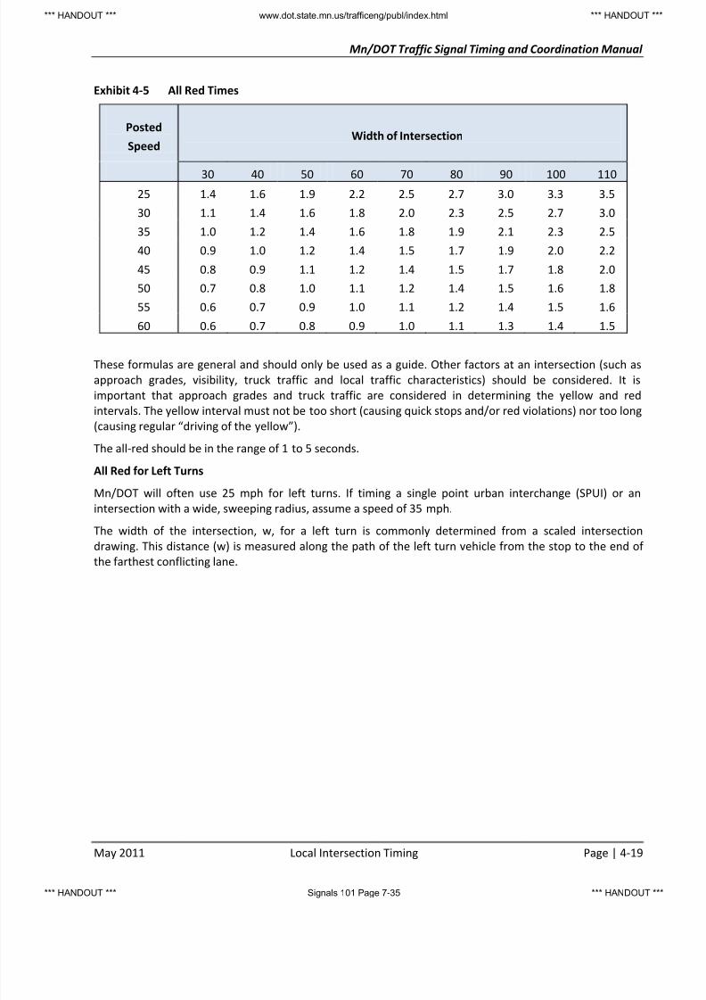
Exhibit 4-5 All Red Times
Posted
SpeedWidth of Intersection
30 40 50 60 70 80 90 100 11025 1.4 1.6 1.9 2.2 2.5 2.7 3.0 3.3 3.5
30 1.1 1.4 1.6 1.8 2.0 2.3 2.5 2.7 3.0
35 1.0 1.2 1.4 1.6 1.8 1.9 2.1 2.3 2.5
40 0.9 1.0 1.2 1.4 1.5 1.7 1.9 2.0 2.2
45 0.8 0.9 1.1 1.2 1.4 1.5 1.7 1.8 2.0
50 0.7 0.8 1.0 1.1 1.2 1.4 1.5 1.6 1.8
55 0.6 0.7 0.9 1.0 1.1 1.2 1.4 1.5 1.6
60 0.6 0.7 0.8 0.9 1.0 1.1 1.3 1.4 1.5
These formulas are general and should only be used as a guide. Other factors at an intersection (such as
approach grades, visibility, truck traffic and local traffic characteristics) should be considered. It is
important that approach grades and truck traffic are considered in determining the yellow and red
intervals. The yellow interval must not be too short (causing quick stops and/or red violations) nor too long
(causing regular “driving of the yellow”).
The all-red should be in the range of 1 to 5 seconds.
All Red for Left Turns
Mn/DOT will often use 25 mph for left turns. If timing a single point urban interchange (SPUI) or an
intersection with a wide, sweeping radius, assume a speed of 35 mph.
The width of the intersection, w, for a left turn is commonly determined from a scaled intersection
drawing. This distance (w) is measured along the path of the left turn vehicle from the stop to the end of
the farthest conflicting lane.
*** HANDOUT *** www.dot.state.mn.us/trafficeng/publ/index.html *** HANDOUT **
*** HANDOUT *** Signals 101 Page 7-35 *** HANDOUT **

8/2/2019 Traffic Signal Field Operations
http://slidepdf.com/reader/full/traffic-signal-field-operations 36/40
Mn/DOT Traffic Signal Timing and Coordination Manual
Page | 4-20 Local Intersection Timing May 2011
Example: Consider the intersection shown in the figure below.
Assume the following:
t = 1.0 seconds
v = 45 mph
a = 10 feet per second
l = 20 feet
g = -1 percent
Y + R = 1.0 + 1.467 (45) + 60 + 20
2{10 + 32.2(-0.01)} 1.467 (45)
Y + AR = 1.0 + 3.41 + 1.21 = 5.62 seconds
Use,
Yellow = 4.4 seconds and All Red = 1.2 seconds
NB Direction:
Grade = -1%
6 0
f e e t
*** HANDOUT *** www.dot.state.mn.us/trafficeng/publ/index.html *** HANDOUT **
*** HANDOUT *** Signals 101 Page 7-36 *** HANDOUT **

8/2/2019 Traffic Signal Field Operations
http://slidepdf.com/reader/full/traffic-signal-field-operations 37/40
Mn/DOT Traffic Signal Timing and Coordination Manual
May 2011 Coordination Concepts Page | 5-1
5. COORDINATION CONCEPTS
Cycle Length
The cycle length is the total time to complete one sequence of signalization around an intersection. In an
actuated controller unit, a complete cycle is dependent on the presence of calls on all phases. In a pre-
timed controller unit (see page 3-5) it is a complete sequence of signal indications.
The equation presented on page 3-1 is for isolated pre-timed signal locations only. A detailed network
analysis should be performed using a software package such as Synchro or TRANSYT for cycle length
determination in a coordinated system. The use of computer models allows for multiple iterations of
varying cycle combinations to determine the optimum signal timing parameters.
Signal Timing Intervals and Splits
The sum of the green, yellow, and all red intervals typically defines an individual phase split. A split is then
the segment of the cycle length allocated to each phase that may occur (expressed in percent or seconds).
The primary considerations that must be given to vehicle split times are as follows:
The phase duration must be no shorter than some absolute minimum time, such as five to sevenseconds of green plus the required clearance interval. If pedestrians may be crossing with this
phase, their crossing time must also be considered and included in the minimum phase length.
A phase must be long enough to avoid over saturating any approach associated with it. Too short a
time will cause frequent cycle failures where some traffic fails to clear during its phase.
A phase length must not be so long that green time is wasted and vehicles on other approaches are
delayed needlessly.
Phase lengths should be properly designed to efficiently balance the cycle time available among the
several phases, not just “equitably” between, say, north-south and east-west.
OffsetThe offset is the time relationship, expressed in seconds or percent of cycle length, determined by the
difference between a fixed point in the cycle length and a system reference point.
Proper determination and application of intersection offsets provide for the efficient movement of
platoons through multiple intersections during the green indication. Properly timed offsets can
significantly reduce delay and improve driver satisfaction with the system timing.
Progression Measures
All of the coordinated system analysis models have some MOEs associated with the green bands in the
Time-Space Diagram (TSD). In fact some of the models utilize progression MOEs as a component of the
optimization objective function. The more common of these MOEs are introduced below.Bandwidth Efficiency
PASSER II uses this measure as its objective function. This is simply the proportion of the cycle that is
included in through green bands, extending the entire length of the system. A simple TSD showing perfect
time-space progression illustrates the concept. Mathematically, efficiency is calculated as:
E =Bf + B r
2C
*** HANDOUT *** www.dot.state.mn.us/trafficeng/publ/index.html *** HANDOUT **
*** HANDOUT *** Signals 101 Page 7-37 *** HANDOUT **

8/2/2019 Traffic Signal Field Operations
http://slidepdf.com/reader/full/traffic-signal-field-operations 38/40
Mn/DOT Traffic Signal Timing and Coordination Manual
Page | 5-12 Coordination Concepts May 2011
Comparisons between “before” and “after” data should be performed for:
System-wide measures-of-effectiveness output from the simulation models, and
Field-collected measures such as travel time.
Also, refer to Chapter 4 for Mn/DOT’s procedure to time a traffic control signal.
Traffic Signal Control Systems
System Concept
A system may be defined as an arrangement or combination of interacting or interdependent parts which
form a unified whole serving a common purpose. The system concept as related to traffic signal control
includes the methods, equipment, and techniques required to coordinate traffic flow along an arterial or
throughout an area.
System Objective
The major objective of a traffic control system is to permit continuous movement and/or minimize delay
along an arterial or throughout a network of major streets. This involves the selection, implementation,
and monitoring of the most appropriate operational plan. Basically, a traffic signal system provides theappropriate and necessary timing plans for each intersection in terms of individual needs as well as the
combined needs of a series of intersections.
Relationship of Timing Plans to Traffic Control
In the system concept a timing plan is defined by a combination of control parameters for one or more
intersections based upon an analysis of demand. Timing plans can be provided as a function of equipment
at the local intersection, the central control point, or both. Timing plans consist of:
1. A system Cycle. A specific cycle length is imposed throughout the system covered by the timing
plan.
2. Split . All intersections in the system have defined splits which are the apportionment of the cycle
to the various phases present at that intersection.
3. Offset . Each intersection has a unique offset. The offset is the relationship of the beginning of the
main street green at this intersection to a master system base time. Offsets are generally
expressed in seconds. Properly established offsets along a street can potentially provide for
smooth traffic flow without stopping.
Basis of Selecting Timing Plans
The selection parameters which define timing plans include:
1. Historic Data Time of Day information compiled from traffic counts to reflect traffic volumes for
specified time of day (morning peak, midday, afternoon peak, etc.) and day of week.
2. Current Data Real time on-street volumes from traffic detection equipment.
3. Special Data Special events, emergency route assignment, special right-of-way preemption (fire
equipment, ambulances, buses, etc.)
Types of Traffic Signal Control Systems
Many combinations of methods, equipment, and techniques can comprise a traffic signal control system.
Generally, these systems fall into the following basic types.
*** HANDOUT *** www.dot.state.mn.us/trafficeng/publ/index.html *** HANDOUT **
*** HANDOUT *** Signals 101 Page 7-38 *** HANDOUT **
8/2/2019 Traffic Signal Field Operations
http://slidepdf.com/reader/full/traffic-signal-field-operations 39/40
Mn/DOT Traffic Signal Timing and Coordination Manual
May 2011 Coordination Concepts Page | 5-13
Time Based Coordinated (TBC) System
This form of coordination utilizes non-interconnected controllers with auxiliary devices called time based
coordinators. These devices use the power company supplied frequency to keep time very accurately.
Various timing plans can be established with time of day and day of week plan changes. Since all
intersections use the same power source, the time-based coordinators provide coordination without
physical interconnection.
Global Positioning System (GPS) receivers have been used for several years to provide a clock sync to
ensure TBC is maintained.
Interconnected Pre-timed System
This type of system was originally developed for electromechanical controllers, but can also be used with
some of the newer controllers. Local intersections are physically interconnected (usually by a 7-wire cable)
to ensure coordinated operation. The system provides automatic re-synchronization should a signal go
“out of step”. The number of timing plans is a function of the number of dials and the number of offsets
and splits per dial; the most common system consists of a three-dial, three-offset, one-split combination.
Timing plans are normally selected by a time clock or time dependent programming device. The local
controller for one intersection may act as master controller for the system.
Traffic Responsive System
Basically, this is an interconnected system utilizing a master controller for pattern (Cycle/offset/splits)
selection. Traffic detectors are used to sample directional volumes and detector occupancy. Volume and
occupancy metrics determine which of the available patterns is selected (i.e., inbound, outbound, or
average) based on predetermined thresholds. The master controller may be an analog or a digital
computer.
Interconnected Actuated Systems
Generally a small system with a master-slave relationship (i.e., two or more fully-or semi-actuated local
controllers with one acting as system master and controlling cycle length for the other controllers). Offset
capability is limited. A variation of this system uses a system master, coordinating units, and local actuated
controllers. The master may be traffic responsive or combination of time clocks.
Traffic Adaptive System
Traffic adaptive systems perform “real-time” adjustments to the cycle length, splits and offsets in response
to traffic demand. Traffic adaptive systems require extensive detection inputs. Complete and accurate
traffic flow data must be gathered, processed and communicated to the central computer.
Advanced Traffic Management Systems (ATMS)
ATMS are capable of monitoring and controlling thousands of intersection controllers using state of the art
architecture like TCP/IP and NTCIP. ATMS offer complete traffic and data management including real time
field reporting for multiple users over distributed local and wide area networks and remote access.ATMS offer scalable software solutions that support a range of users including:
School zone flashers
Freeway management
CMS, VMS, DMS
CCTV surveillance
*** HANDOUT *** www.dot.state.mn.us/trafficeng/publ/index.html *** HANDOUT **
*** HANDOUT *** Signals 101 Page 7-39 *** HANDOUT **

8/2/2019 Traffic Signal Field Operations
http://slidepdf.com/reader/full/traffic-signal-field-operations 40/40
Mn/DOT Traffic Signal Timing and Coordination Manual
HOV lane control
Reversible lane control signals
Real-time split monitoring and time space reporting
Incident detection
Light rail control systems
Transit priority systems
1.5 generation timing plan development using Synchro or PASSER
2.0 Generation control (Traffic Responsive and Traffic Adaptive)
Integrated video detection
Real time preemption log retrieval
Time-Space Diagrams
These are prepared to determine the offsets on individual intersections.
A time-space diagram is a chart on which distance is plotted against time. The location of each signalized
intersection is plotted along one axis. At each such point the signal color sequence and split are plotted in
such a manner that through bands are available for each direction of traffic flow. The slope of the through
band (distance divided by time) is the speed of progression, and width indicates the time available for a
platoon traveling through systems.
For two-way streets, the diagram is usually prepared to give equal consideration to each direction of
travel. Where appropriate types of program controllers are available, separate peak-hour diagrams are
prepared for streets carrying heavy directional peak volumes; these will favor travel in the peak direction.
The cycle length may be changed (for the entire system) and the offsets are changed through the use of
time clocks in the master controller. Sample time-space diagrams for off-peak and evening peak periods
are shown in the figures below.
When a coordinated system is established for a certain speed during all periods of the day, supplemental
signs may be erected which inform the driver of that speed.
*** HANDOUT *** www.dot.state.mn.us/trafficeng/publ/index.html *** HANDOUT **
Top Related