


Languages
Pages
Legal


NDOT Research Report
Report No. 701-18-803 TO 2
TPF-5(358) IMPROVING CONNECTIVITY: INNOVATIVE FIBER-REINFORCED POLYMER STRUCTURES FOR WILDLIFE, BICYCLISTS, AND/OR PEDESTRIANS
July 2020
Nevada Department of Transportation 1263 South Stewart Street Carson City, NV 89712
Contributing Partners Alaska DOT ARC Solutions, Inc. Arizona DOT California DOT Iowa DOT Ontario Ministry of Transportation Oregon DOT Michigan DOT Minnesota DOT New Mexico DOT Parks Canada Washington DOT

Disclaimer
This work was sponsored by the Nevada Department of Transportation. The contents of this report reflect the views of the authors, who are responsible for the facts and the accuracy of the data presented herein. The contents do not necessarily reflect the official views or policies of the State of Nevada at the time of publication. This report does not constitute a standard, specification, or regulation.

TECHNICAL REPORT DOCUMENTATION PAGE
1. Report No. P701-18-803 TO 2
2. Government Accession No. 3. Recipient’s Catalog No.
4. Title and Subtitle Improving Connectivity: Innovative Fiber-Reinforced Polymer Structures for Wildlife, Bicyclists, and/or Pedestrians A Report for Tasks 1-4
5. Report Date August 4, 2020 6. Performing Organization Code
7. Author(s) Mat Bell, Rob Ament, Damon Fick
8. Performing Organization Report No.
9. Performing Organization Name and Address Western Transportation Institute College of Engineering Montana State University Bozeman, MT
10. Work Unit No.
11. Contract or Grant No. P701-18-803 TO 2
12. Sponsoring Agency Name and Address Nevada Department of Transportation 1263 South Stewart Street Carson City, NV 89712
13. Type of Report and Period Covered Final Report March – May 2020 14. Sponsoring Agency Code
15. Supplementary Notes
16. Abstract Ecologists and engineers are constantly exploring new methods and adapting existing techniques to improve mitigation measures that increase motorist safety and wildlife species conservation. Crossing structures, combined with fences, are some of the most highly effective mitigation measures that are employed around the world due to their ability to not only reduce wildlife-vehicle collisions (WVCs) with large animals and increase motorist safety, but they also provide an additional benefit that other measures don’t, they help maintain habitat connectivity across transportation networks for many types and sizes of wildlife. Published research on bridge designs and materials for wildlife crossings is limited and suggests relatively little innovation has occurred. Given wildlife crossing structures are a critical contribution to highway mitigation strategies for reducing WVCs while also providing for habitat connectivity, species movement and migrations, the need for new, resourceful, and innovative techniques is warranted. This report explores the promising application of fiber-reinforced polymers (FRPs) to wildlife crossing structures. If FRP structural designs can meet all bridge specifications set by transportation agencies and prove to have less expensive life cycles, they will provide a new approach that is more efficient, more quickly deployed, lasts longer, requires less maintenance and is ultimately more adaptable than traditional materials. This project explores what is know about FRP bridge structures and materials that can be adapted for use in crossing structures over highways for wildlife and, by extension, for bicyclists and pedestrians as well.
17. Key Words Wildlife crossing, fiber reinforced polymer structure,
fiber reinforced polymer materials, bridge, wildlife vehicle collision, highway safety, mitigation measure
18. Distribution Statement No restrictions. This document is available through the: National Technical Information Service Springfield, VA 22161
19. Security Classif. (of this report) Unclassified
20. Security Classif. (of this page) Unclassified
21. No. of Pages 39
22. Price
Form DOT F 1700.7 (8-72) Reproduction of completed page authorized

Improving Connectivity: Innovative Fiber-Reinforced Polymer Structures
for Wildlife, Bicyclists, and/or Pedestrians
Report for Tasks 1-4
by
Matthew Bell, Rob Ament, Damon Fick, Marcel Huijser
Western Transportation Institute
College of Engineering
Montana State University
A report prepared for the
Small Urban, Rural, and Tribal Center on Mobility (SURTCOM)
http://surtcom.org/
and
Animal Road Crossing (ARC) Solutions
PO Box 1587
Bozeman, MT
59771
August 6, 2020

Fiber-Reinforced Polymer use for Wildlife Crossing Infrastructure List of Tables
i
TABLE OF CONTENTS
1. Background 5
2. Project Tasks ........ 6 .....................................................................................................................
...............................................................................................................................
2.1. Task 1: Literature Review 6 ................................................................................................
2.2. Task 2: Evaluate FRP Manufacturers and their Products 7 ................................................
2.3. Task 3: Structural Testing and Analysis of Materials 7 ......................................................
..........2.4. Task 4: Select Best use of FRP Materials for Wildlife Infrastructure
...........
7
3. Literature Review
..........
8
3.1. Fiber-Reinforced Polymers 8
3.1.1. Sustainability 8
3.1.2. Resins 9
3.1.3. Fibers 10
3.2. FRP Materials for Road and Bridge Infrastructure 12
3.2.1. FRP Manufacturing Process 12
3.2.2. Hybrid Bridge Members 14
3.2.3. Singularly Molded (uni-mold) Bridges 18
3.3. Summary 19
4. Evaluate FRP Manufacturers and their Products
.......
...................
..........................................................................................................
..............................................................................................
.............................................................................................................
........................................................................................................................
.......................................................................................................................
........................................................
.........................................................................
.........................................................................................
............................................................
........................................................................................................................
20 ....................................................................
......................................................................4.1. FRP Manufacturers for Bridge Elements 20 .
.........................................................................5. Structural Testing and Analysis of Materials 22
.....................................................6. Select Best use of FRP Materials for Different Structures 23
..................................................................................... 6.1. FRP Wildlife Overpass Designs 23
................................................................................................... 6.1.1. Pultrusion Bridges 23
........................................................................................................ 6.1.2. Hybrid Bridges 25
6.1.3. Uni-mold Bridges ....... 31 .............................................................................................
6.2. Wildlife Underpass 32 .........................................................................................................
6.3. Jump-outs, Fences, and Barriers 33
6.3.1. American Plastic Lumber, Inc.
....................................................................................
34 ..........
..........
........
.....................................................................
6.4. FRP Materials Available for the Project’s Design Tasks 34 .....................................
7. Discussion 36 ...............................................................................................................................
8. References 37 ..............................................................................................................................
........................................................................................................................9. Appendix 41

Fiber-Reinforced Polymer use for Wildlife Crossing Infrastructure List of Tables
ii
LIST OF TABLES
Table 1: Stress-strain relationship of the various kinds of FRP composites in comparison with steel
reinforcement [21] 11 . ...............................................................................................................
Table 2: Mechanical properties of flax, hemp, jute, e-glass, and basalt fibers [16] 11 . ....................
Table 3: Summary of the selected FRP manufacturers that are capable of supplying bridge spans
or associated elements for wildlife crossing structures 21 .........................................................
Table 4: Selected FRP manufacturers best fit for designing and building wildlife crossing
infrastructure 35 . ........................................................................................................................
Table 5: Contact information for leading manufacturers capable of creating materials necessary
for an FRP wildlife crossing overpass 41 . .................................................................................
Table 6: A summary of the technical data available for each FRP manufacturer available on their
websites. Some of the manufacturers have additional data available, where some of them have
none do to the complexity and design characteristics of creating vacuum molded FRP
structures. 42 ..............................................................................................................................

Fiber-Reinforced Polymer use for Wildlife Crossing Infrastructure List of Figures
iii
LIST OF FIGURES
Figure 1: General configuration of structural fibers distributed throughout thermoset resin [18]. 8
Figure 2: Schema of how pultrusion members are formed [47] 13 . ..................................................
Figure 3: Example of pultrusion-style pedestrian bridge in Marshall, CA. Bridge spans 29 m and
is 1.8 m wide. With a live-load design of 2.83 kilopascals (kPa), or 60 pounds per square foot
(psf), the FRP members are connected with galvanized steel bolts [18] 13 . .............................
Figure 4: Glass FRP arched pedestrian bridge, 38m x 3m, Lleida, Spain. Railway and vehicle
traffic only blocked for three hours during construction [48] 13 ...............................................
Figure 5: Schema for how vacuum assisted resin transfer molded structures are formed [49] 14 . ...
. ....................................................................................................
Figure 6: A 21.5 m FRP deck placed on top of steel girders to create a traffic bridge over B3
highway in Germany [50] 15
Figure 7: Schema of the CFFT bridge design developed by Advanced Infrastructure Technologies.
16 ...............................................................................................................................................
Figure 8: Different geometry applications of CFFT bridge spans [59] 17 . .......................................
. .....
Figure 9: The Perkins Bridge in Belfast, Maine, made with a CFFT and FRP panels. The bridge
spans 47ft 7 inches (in), has an 11ft rise, and is 45ft wide. It is made with 16, 15in diameter
tubes. Each arch weighed 250 pounds (lbs) before they were filled with concrete [61] 17
Figure 10: Installation of a uni-mold FRP ecoduct near Eindhoven, The Netherlands. Bridge is
36m x 3.5m [63]. Top left; bridge is delivered in one piece from the factory to the construction
site. Top right; bridge is lifted into place using one crane. Bottom; FRP ecoduct is placed onto
abutments over a canal 18 . .........................................................................................................
Figure 11: Example of a pedestrian bridge built by Creative Pultrusions. This bridge is in Bear
Mountain, New York, and is 62ft x 6ft with a strait design using FRP railings for trusses and
FRP decking for the walkway 24 . ..............................................................................................
Figure 12: Example of FRP bridge made by Guardian Bridge Rapid Construction for a two lane
road over a creek, the bridge spans 15m; (Left) a triple-tee span being placed by a crane,
(Right) all three spans placed on top of an FRP abutment 25 . ..................................................
Figure 13: Design by Guardian Bridge Rapid Construction of a wildlife crossing structure for ARC
Solution’s design competition. 26 ..............................................................................................
Figure 14: The schema of an HCB designed by Hillman Composite Beams. 26 ..............................
Figure 15: Hillman Composite Beam’s HCB bridge near Lockwood, Missouri. The bridge consists
of three beams that span 106ft, are 5ft tall, 6ft wide, and support a 30ft 8in wide deck. (Left)
Completed bridge. (Right) One of the HCBs being transported on a truck 27 . .........................
. ............................................................................................................................
Figure 16: CFFT bridge built by AIT in Augusta, Maine. The bridge uses 22, 15in diameter carbon-
fiber tubes to make a span of 54ft, is 55ft wide, and has a rise of 12ft above the concrete
abutments to allow enough clearance for traffic once they are placed on the pre-cast concrete
foundation 28

Fiber-Reinforced Polymer use for Wildlife Crossing Infrastructure List of Figures
iv
Figure 17: A section of a CT Girder made by AIT. Foam inserts can be seen in the vertical walls
of the girder to help reduce the weight 30 . ................................................................................
Figure 18: Comparison between AIT’s CFFT bridge and Con/Span’s precast concrete designs. 31
Figure 19: The longest, unsupported, uni-mold bridge built by FiberCore Europe using InfraCore®
technology. The bridge is 37m x 3.5m and has a design-load of 5kN/m2 (~104psf) 32 . ..........
Figure 20: Pultrusion-style train bridge built from recycled plastic. Axion Structural Innovations
created two spans of 40ft and 80ft that can support 130-ton locomotives 33 . ...........................

Fiber-Reinforced Polymer use for Wildlife Crossing Infrastructure Project Tasks
5
1. BACKGROUND
Ecologists and engineers are constantly exploring new methods and adapting existing techniques
to improve mitigation measures that increase motorist safety and wildlife species conservation. It
is estimated that over one million wildlife-vehicle collisions (WVCs) with large mammals occur
annually in the United States, which result in billions of dollars of property damage, personal
injuries, and fatalities [1, 2]. There are currently various types of WVC mitigation measures (e.g.,
underpasses and overpasses with fencing, standard and enhanced signs, animal detection-driver
warning systems), that when designed and used properly, can reduce collisions with wildlife up to
99% [3-7]. Crossing structures, combined with fences, are some of the most highly effective
mitigation measures that are employed around the world due to their ability to not only reduce
WVCs with large animals and increase motorist safety, but they also provide an additional benefit
that other measures don’t, they help maintain habitat connectivity across transportation networks
for many types and sizes of wildlife [8, 9].
The length and width of wildlife overpasses continue to challenge engineers and architects. Recent
designs span over six lanes of traffic and are anticipated to exceed 10 lanes soon, i.e. Highway 101
in Liberty Canyon, California. This will require bridge spans up to 60 meters (m). Common widths
of wildlife overpasses have been designed from 30-60 m, and even wider. These design
requirements result in massive structures, that support heavy loads that incorporate soils that host
native habitats, sometimes including forests. Designing overpass structures to support these types
of static and environmental loads over multi-lane highways results in high construction costs (e.g.
materials, skilled labor, heavy lifting equipment, construction time). Recent price-tags for wildlife
individual overpasses near Banff, Alberta, Canada, cost over $4 million USD and a current
estimate for the Highway 101 overpass in Liberty Canyon is around $50 million USD [6].
Not all wildlife crossing structures are located in forested environments or are designed for a focal
species that requires hiding cover and large amounts of vegetation on the structure. The location
of these structures, in conjunction with fencing, depends on a highway’s WVC rates, wildlife
movement needs, local topography, and other specific site factors. Often, because of their cost
relative to other mitigation measures, they are used sparingly. However, because almost 90% of
all WVCs in the United States occur on two lane roads [1], shorter spans and more economical
structures are possible. For example, in the largely rural state of Montana, nine out of the top ten
WVC hotspots during the fall migrations of wildlife occur on two-lane highways [10]. Thus, many,
if not most overpasses and other types of crossing structures will address short spans.
Overpass structures have been designed by engineers using pre-cast or cast-in-place concrete, steel
arches, or a mix of the two materials. The landscape surface is often designed after the completion
of the overpass, although there is evidence that projects may be more successful if the integration
of landscape components are considered during the preliminary or initial design stage. The use of
concrete and steel materials have limitations that include long construction durations that result in
traffic control, delays, and detours for up to six months or more. The large size and limited mobility
of equipment required during erection of the superstructure also contribute to construction
inefficiency.
In addition to the restrictions with construction and design, concrete and steel are less durable due
to environmental freeze-thaw cycles that results in cracking, salt intrusion, and reinforcement
corrosion. For steel structures, regular under deck inspections are required to identify potential

Fiber-Reinforced Polymer use for Wildlife Crossing Infrastructure Project Tasks
6
fatigue cracks or corrosion. For steel members made from non-weathering steels, routine painting
is required maintenance. At the end of their service life, these permanent structures often require
significant rehabilitation and/or increased maintenance, making bridge replacement a more
economical option for bridge owners. Recent research found that steel bridges are at risk of
increased structural failure rates during normal loading if average temperatures continue to rise
over the next 100 years [11]. Areas in the northern U.S. are more likely to see this effect due to
the more pronounced difference between the temperatures at the time a steel bridge was
constructed, and the predicted future temperatures. Moreover, approximately 5% of global
CO2 emissions originate from the manufacturing of cement, and it is the third largest source of
carbon emission in the United States [12].
Published research on bridge designs and materials for wildlife crossings is limited and suggests
relatively little innovation has occurred [13]. Given wildlife crossing structures are a critical
contribution to highway mitigation strategies for reducing WVCs while also providing for habitat
connectivity, species movement and migrations, the need for new, resourceful, and innovative
techniques is warranted.
This report documents Tasks 1-4 of this research project that explores the promising application
of fiber-reinforced polymers (FRPs) to wildlife crossing structures. If FRP structural designs can
meet all bridge specifications set by transportation agencies and prove to have less expensive life
cycles, they will provide a new approach that is more efficient, more quickly deployed, lasts
longer, requires less maintenance and is ultimately more adaptable than traditional materials.
2. PROJECT TASKS
The first four tasks of this project were to 1) conduct a literature review on what is known regarding
the use of Fiber Reinforced Polymer (FRP) materials or hybrid materials in bridge construction;
2) evaluate manufactures and FRP materials that would be available in the North American market
for use in wildlife crossing infrastructure, as well as bicycle and pedestrian (bike-ped) bridges; 3)
conduct new testing or synthesizes existing test data of FRP materials that could be used by this
project’s infrastructure designs; and, 4) based on reviews and testing, select the best available
products and their manufacturers that can be used for wildlife, bicycle and pedestrian crossing
infrastructure. This task report documents the specific activities of Tasks 1-4 and their outcomes.
A brief summary of these tasks is provided below.
2.1. Task 1: Literature Review
A literature review was conducted on existing FRP manufacturers, materials, components, and
systems. This review incorporated systems currently used for bicycle pedestrian (bike-ped), with
consideration of those applicable for use as wildlife crossings. Information on life cycle cost
including maintenance costs and FRP durability over time is summarized. This review includes
sources from the National Academies’ Transportation Research Board, State Departments of
Transportation, Universities, and national and international engineering and related science
journals.
Fiber-Reinforced Polymer use for Wildlife Crossing Infrastructure Project Tasks
7
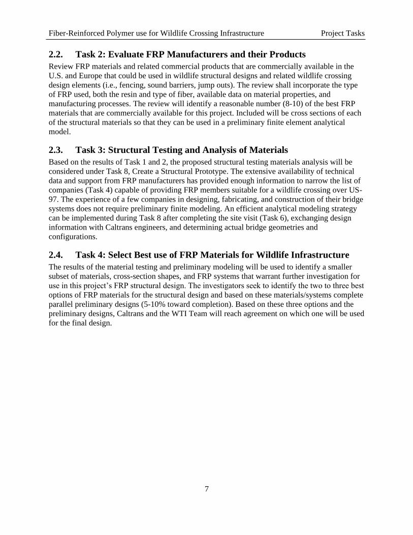
2.2. Task 2: Evaluate FRP Manufacturers and their Products
Review FRP materials and related commercial products that are commercially available in the
U.S. and Europe that could be used in wildlife structural designs and related wildlife crossing
design elements (i.e., fencing, sound barriers, jump outs). The review shall incorporate the type
of FRP used, both the resin and type of fiber, available data on material properties, and
manufacturing processes. The review will identify a reasonable number (8-10) of the best FRP
materials that are commercially available for this project. Included will be cross sections of each
of the structural materials so that they can be used in a preliminary finite element analytical
model.
2.3. Task 3: Structural Testing and Analysis of Materials
Based on the results of Task 1 and 2, the proposed structural testing materials analysis will be
considered under Task 8, Create a Structural Prototype. The extensive availability of technical
data and support from FRP manufacturers has provided enough information to narrow the list of
companies (Task 4) capable of providing FRP members suitable for a wildlife crossing over US-
97. The experience of a few companies in designing, fabricating, and construction of their bridge
systems does not require preliminary finite modeling. An efficient analytical modeling strategy
can be implemented during Task 8 after completing the site visit (Task 6), exchanging design
information with Caltrans engineers, and determining actual bridge geometries and
configurations.
2.4. Task 4: Select Best use of FRP Materials for Wildlife Infrastructure
The results of the material testing and preliminary modeling will be used to identify a smaller
subset of materials, cross-section shapes, and FRP systems that warrant further investigation for
use in this project’s FRP structural design. The investigators seek to identify the two to three best
options of FRP materials for the structural design and based on these materials/systems complete
parallel preliminary designs (5-10% toward completion). Based on these three options and the
preliminary designs, Caltrans and the WTI Team will reach agreement on which one will be used
for the final design.
Fiber-Reinforced Polymer use for Wildlife Crossing Infrastructure Literature Review
8
3. LITERATURE REVIEW
3.1. Fiber-Reinforced Polymers
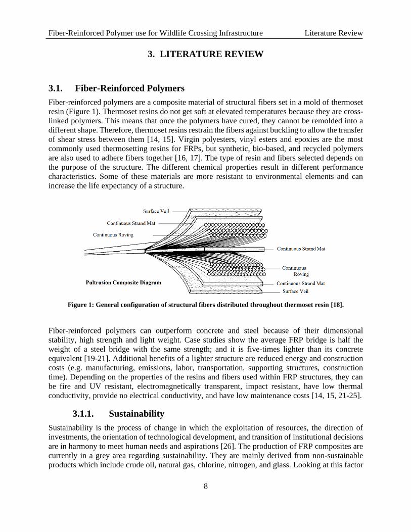
Fiber-reinforced polymers are a composite material of structural fibers set in a mold of thermoset
resin (Figure 1). Thermoset resins do not get soft at elevated temperatures because they are cross-
linked polymers. This means that once the polymers have cured, they cannot be remolded into a
different shape. Therefore, thermoset resins restrain the fibers against buckling to allow the transfer
of shear stress between them [14, 15]. Virgin polyesters, vinyl esters and epoxies are the most
commonly used thermosetting resins for FRPs, but synthetic, bio-based, and recycled polymers
are also used to adhere fibers together [16, 17]. The type of resin and fibers selected depends on
the purpose of the structure. The different chemical properties result in different performance
characteristics. Some of these materials are more resistant to environmental elements and can
increase the life expectancy of a structure.
Figure 1: General configuration of structural fibers distributed throughout thermoset resin [18].
Fiber-reinforced polymers can outperform concrete and steel because of their dimensional
stability, high strength and light weight. Case studies show the average FRP bridge is half the
weight of a steel bridge with the same strength; and it is five-times lighter than its concrete
equivalent [19-21]. Additional benefits of a lighter structure are reduced energy and construction
costs (e.g. manufacturing, emissions, labor, transportation, supporting structures, construction
time). Depending on the properties of the resins and fibers used within FRP structures, they can
be fire and UV resistant, electromagnetically transparent, impact resistant, have low thermal
conductivity, provide no electrical conductivity, and have low maintenance costs [14, 15, 21-25].
3.1.1. Sustainability
Sustainability is the process of change in which the exploitation of resources, the direction of
investments, the orientation of technological development, and transition of institutional decisions
are in harmony to meet human needs and aspirations [26]. The production of FRP composites are
currently in a grey area regarding sustainability. They are mainly derived from non-sustainable
products which include crude oil, natural gas, chlorine, nitrogen, and glass. Looking at this factor

Fiber-Reinforced Polymer use for Wildlife Crossing Infrastructure Literature Review
9
may make it seem like FRP materials cannot be sustainable, but sustainability is measured by a
number of factors (e.g. minimum resource use, low environmental impact, low human health risk,
sustainable site design, higher performance, etc.) [27].
The manufacturing of virgin FRP materials produces less greenhouse gases and energy
consumption than manufacturing of steel, aluminum, and concrete [28]. When FRP composites
are compared to other traditional materials like wood and terra cotta, the total life-cycle assessment
of FRP contributes to its viability as a green building product, and now qualifies for many credits
under the Leadership in Energy and Environmental Design (LEED) building rating [29]. The initial
price of FRP materials and manufacturing is generally higher than other traditional methods, but
when life-cycle analyses include external costs (e.g. environmental, sustainability, social, etc.) and
service life, FRP construction is favored by up to 14% [30]. As FRP technologies advance and
become more accepted the initial cost is likely to decrease. Furthermore, incorporating more bio-
based resins and recycled materials will favor the use of FRPs over traditional methods. Using
FRP materials in place of steel and concrete for bridge construction significantly reduce the carbon
and energy footprint during the construction stage, and even further during the 100-year service
life of FRP structures [31].
There are two main techniques to recycling FRP materials after their service life – they can be
ground up and used as a fillers or broken down to repurpose the resin and fibers [32]. The best
method of recycling is to reclaim the fibers and use them in other composites, and the left over
resin powder can be used in cement kilns to replace coal [33]. Carbon fibers are better at retaining
their strength and thermal properties better than glass after they are repurposed from FRPs [34].
3.1.2. Resins
The type of resin used to manufacture FRP materials directly relates to the beneficial properties of
these structures to resist various physical (e.g. wheel rolling, collisions, debris) and environmental
(e.g. moisture, oxidation, ultra-violet [UV] rays) impacts [15]. Although every material has some
form of degradation, these effects can be significantly reduced by changing the chemical
composition of the polymers. The addition of stabilizers can improve the performance to some
degree. Other types of fillers can increase electrical and thermal conductivity (e.g. aluminum
powders, carbon fibers, and graphite), improve bonding of polymers to fibers (e.g. silanes and
titanites), act as flame retardants (e.g. chlorine, bromine, phosphorous, and metallic salts), reduce
costs (e.g. calcium carbonate, silica, and clay), and change resin colors (e.g. metal oxides,
chromates, and carbon blacks). Generally, the smaller the particles added, the greater the boost in
stiffness, but the original resin begins to lose impact strength as the level of fillers increases [35].
The FRP resistance to environmental factors, therefore, can only be risen to a certain degree before
the mechanical properties of the material are affected.
Material testing on glass and carbon FRP shows that after 1000 hours of exposure to environmental
conditions (e.g. fresh and saltwater, dry heat, alkali, freeze-thaw, UV, and gasoline fuel) there was
less than a 10% change in the elastic properties, and the change in tensile strength was less than
15% when comparing mean values [22]. Absorbing stabilizing agents can improve the resistance
to degradation. Zinc and titanium dioxide nanoparticles, for example, allow only 5% of the
degradation that occurred on the unprotected FRP after a week of UV exposure [23]. Furthermore,
these tests commonly expose FRP materials to levels of UV exposure not found on earth, i.e. short
wavelengths less than 290 nanometer (nm). Longer wavelengths of 365 nm, equal to the UV rays
Fiber-Reinforced Polymer use for Wildlife Crossing Infrastructure Literature Review
10
that make it through the ozone, were found to be incapable of inducing a chemical change in high
molecular weight polymer structures [36].
Another characteristic of FRP structures that can be improved through resin fillers is their water
resistance, which is relevant in many types of moisture exposed applications (e.g. marine lock-
gates and pilings, decking, sewage pipe and wastewater ductwork, water filtration and storage, oil
pipelines). Their moisture resistance is determined by the manufacturing process and the chemical
composition of the FRP. These properties allow the resins to reduce the amount of water absorbed
and limit swelling of the FRP. Some resins can absorb water through osmosis at a microscopic
level, but the process is reversed when the FRP is dried [15]. If resins swell with water and then
dry, this can increase the degradation rate of the polymer [25]. However, applications of moisture
resistant resins can be applied to the outside of the FRP structure if the use of these resins become
cost prohibitive for use throughout the entire mold.
Manufacturing FRP composites is most commonly done using virgin resins, but the use of bio-
based polymers and recycled plastics are becoming more common as researchers and engineers
try to develop more sustainable solutions with eco-friendly products. Bio-based polymers are
synthetic materials that are processed from vegetable products (e.g. starch, proteins, and oils).
These products are commonly derived from soy beans, potatoes, corn, and flax, but can also be
derived from a large number of other grains and seeds [37]. Bio-based resins still have a long-life
span but do degrade faster than virgin polymer-based resins. This is even more pronounced when
the resins are recycled. The use of recycled polymers has been associated with a downgrade of
mechanical properties [16]. This creates challenges for using them in FRP structures because they
are more difficult to include complex fiber distribution throughout the mold. Therefore, recycled
plastics are commonly used in non-structural applications.
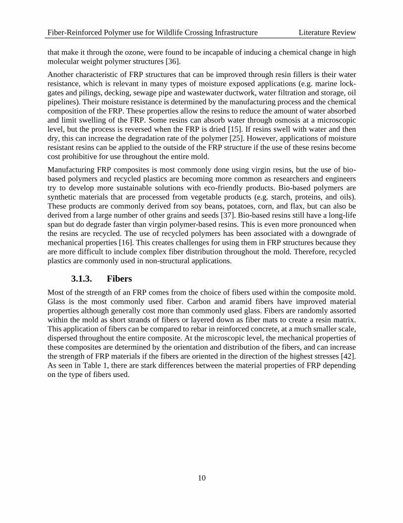
3.1.3. Fibers
Most of the strength of an FRP comes from the choice of fibers used within the composite mold.
Glass is the most commonly used fiber. Carbon and aramid fibers have improved material
properties although generally cost more than commonly used glass. Fibers are randomly assorted
within the mold as short strands of fibers or layered down as fiber mats to create a resin matrix.
This application of fibers can be compared to rebar in reinforced concrete, at a much smaller scale,
dispersed throughout the entire composite. At the microscopic level, the mechanical properties of
these composites are determined by the orientation and distribution of the fibers, and can increase
the strength of FRP materials if the fibers are oriented in the direction of the highest stresses [42].
As seen in Table 1, there are stark differences between the material properties of FRP depending
on the type of fibers used.

Fiber-Reinforced Polymer use for Wildlife Crossing Infrastructure Literature Review
11
Table 1: Stress-strain relationship of the various kinds of FRP composites in comparison with steel
reinforcement [21].
The use of natural fibers is gaining popularity because of the energy input required to produce
inorganic synthetic fibers (e.g. glass, carbon). Bio-based fibers can be derived from plants (e.g.
seeds, stems, fruit, leaves, grass) and animals (e.g. fur, wool, silk). Some of the strongest plant
based fibers include flax, hemp, and jute [16]. However, their mechanical strengths are less than
inorganic synthetic fibers as shown in Table 2. One of the main drawbacks of natural fibers are
also less structurally durable. They are more flammable and water absorbent and degrade faster
from UV radiation.
Table 2: Mechanical properties of flax, hemp, jute, e-glass, and basalt fibers [16].
The fiber volume ratio is determined by the percentage of fibers within the total volume of the
composite. Using the same type of fibers, higher fiber volume ratio typically result in better
mechanical properties of FRP composites [43]. Depending on the composite material design
requirements, the optimal fiber volume ratio is between 30-70%. The ratio can be as high as 90%
if all the fibers are in the unidirectional orientation, but a decrease in strength can occur because
there is not enough space for the resins to fully surround and bond with the fibers [44].
The type and configuration of fibers is also based on the desired strength requirements. The
material properties of FRP composites can be determined by two methods: experimental strength
analysis or theoretical micromechanics. Experimental strength analysis uses structural testing to
identify limits of stress and strain under tension, compression, and shear loading. The theoretical
method evaluates the individual strengths of fibers and resins at the microscopic level then adds
Fiber-Reinforced Polymer use for Wildlife Crossing Infrastructure Literature Review
12
their strengths together. The strength properties of the FRP using the theoretical method are
calculated using known fiber and resin material properties and volume ratios.
3.2. FRP Materials for Road and Bridge Infrastructure
The application of FRP composites in transportation began during World War II where they were
used for airplane parts. More recently, these materials are now commonly used in multiple types
of road and bridge infrastructure that includes, asphalt; structural pilings and decking in marine
settings; water drainage systems; FRP wraps for repair and strengthening of concrete, metal and
wood structures; FRP reinforcement in concrete; traffic barriers/fenders; and multiple types of
pedestrian and traffic bridge applications [20, 21, 45].
The creation of FRP lumber in the 1990’s allowed engineers to create different applications for
this adaptable and long-lasting composite. One of the first reported FRP pedestrian bridge was
created in 1995 in Harlingen, the Netherlands [20], while the first vehicular bridge made of FRP
composites was built in 1998 in Fort Leonard Wood, Missouri. The U.S. Army continued to make
advancements and built the first vehicular bridge made of recycled plastics in 2009 in Fort Bragg,
North Carolina, that is capable of carrying a 70-ton military tank [38].
3.2.1. FRP Manufacturing Process
Many advancements made in the design and manufacturing process of FRP materials over the last
three decades have resulted in currently two techniques used to create FRP products for civil
infrastructure: pultrusion molding and vacuum assisted resin transfer molding. Each
manufacturing process creates different types of structural members that allows engineers to create
custom shapes and molds to fit project needs. The construction costs of FRP bridges are
competitive with other materials, however the life-cycle costs are significantly less for FRP
materials [31]. Furthermore, the offsite fabrication and light weight characteristics contribute to
more efficient on-site construction.
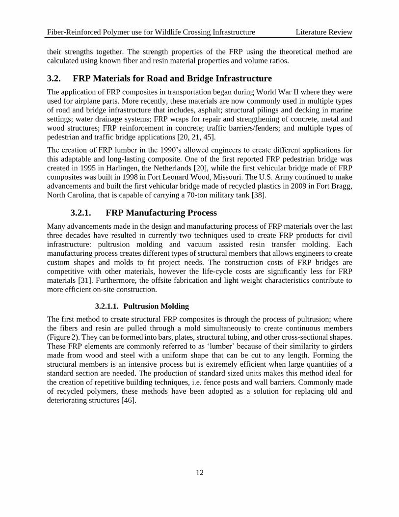
3.2.1.1. Pultrusion Molding
The first method to create structural FRP composites is through the process of pultrusion; where
the fibers and resin are pulled through a mold simultaneously to create continuous members
(Figure 2). They can be formed into bars, plates, structural tubing, and other cross-sectional shapes.
These FRP elements are commonly referred to as ‘lumber’ because of their similarity to girders
made from wood and steel with a uniform shape that can be cut to any length. Forming the
structural members is an intensive process but is extremely efficient when large quantities of a
standard section are needed. The production of standard sized units makes this method ideal for
the creation of repetitive building techniques, i.e. fence posts and wall barriers. Commonly made
of recycled polymers, these methods have been adopted as a solution for replacing old and
deteriorating structures [46].

Fiber-Reinforced Polymer use for Wildlife Crossing Infrastructure Literature Review
13
Figure 2: Schema of how pultrusion members are formed [47].
Pultrusion-style pedestrian bridges are assembled using steel and lumber construction methods,
commonly connected with stainless-steel bolts. Examples of a FRP pultrusion style pedestrian
bridge can be seen in Figure 3 and Figure 4.
Figure 3: Example of pultrusion-style pedestrian bridge in Marshall, CA. Bridge spans 29 m and is 1.8 m
wide. With a live-load design of 2.83 kilopascals (kPa), or 60 pounds per square foot (psf), the FRP members
are connected with galvanized steel bolts [18].
Figure 4: Glass FRP arched pedestrian bridge, 38m x 3m, Lleida, Spain. Railway and vehicle traffic only
blocked for three hours during construction [48].

Fiber-Reinforced Polymer use for Wildlife Crossing Infrastructure Literature Review
14
3.2.1.2. Vacuum Assisted Resin Transfer Molding
The second fabrication method to create FRP structures is the use of vacuum assisted resin transfer
molding; a process that pumps resin through custom shaped molds with the desired fiber layouts
(Figure 5). This manufacturing technique is used to create custom molded shapes and is able to
integrate other materials for different applications of civil infrastructure. Core inserts can be
applied in geometric formations (e.g., squares and hexagons) to reduce weight by creating void
spaces that reduce the amount of resin and fibers required. For these cases, the fibers are arranged
around the core material to produce strong, lightweight, and durable FRP structures. The molds
can result in free-formed standalone (Uni-mold) FRP bridges or designed as large decks and
casings that are constructed with steel and/or concrete materials to create hybrid FRP structures.
Figure 5: Schema for how vacuum assisted resin transfer molded structures are formed [49].
3.2.2. Hybrid Bridge Members
Hybrid structures consist of the integration of FRP composites with other materials, i.e. concrete,
steel, and space-fillers. Several types of hybrid bridge members are currently being used to
combine the benefits of FRP with the familiarity and experience that exists with these traditional
materials. Three such systems include FRP decking placed on traditional steel or concrete girders,
hybrid composite beams, and concrete filled FRP tubes.
Fiber-Reinforced Polymer use for Wildlife Crossing Infrastructure Literature Review
15
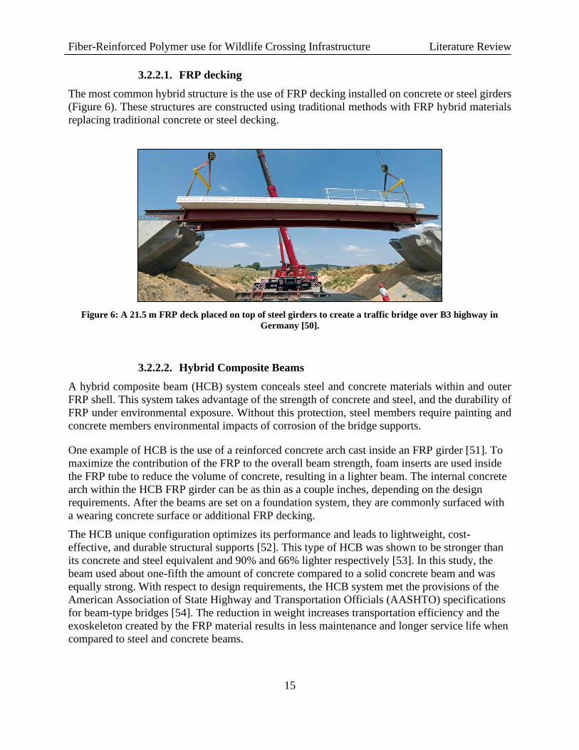
3.2.2.1. FRP decking
The most common hybrid structure is the use of FRP decking installed on concrete or steel girders
(Figure 6). These structures are constructed using traditional methods with FRP hybrid materials
replacing traditional concrete or steel decking.
Figure 6: A 21.5 m FRP deck placed on top of steel girders to create a traffic bridge over B3 highway in
Germany [50].
3.2.2.2. Hybrid Composite Beams
A hybrid composite beam (HCB) system conceals steel and concrete materials within and outer
FRP shell. This system takes advantage of the strength of concrete and steel, and the durability of
FRP under environmental exposure. Without this protection, steel members require painting and
concrete members environmental impacts of corrosion of the bridge supports.
One example of HCB is the use of a reinforced concrete arch cast inside an FRP girder [51]. To
maximize the contribution of the FRP to the overall beam strength, foam inserts are used inside
the FRP tube to reduce the volume of concrete, resulting in a lighter beam. The internal concrete
arch within the HCB FRP girder can be as thin as a couple inches, depending on the design
requirements. After the beams are set on a foundation system, they are commonly surfaced with
a wearing concrete surface or additional FRP decking.
The HCB unique configuration optimizes its performance and leads to lightweight, cost-
effective, and durable structural supports [52]. This type of HCB was shown to be stronger than
its concrete and steel equivalent and 90% and 66% lighter respectively [53]. In this study, the
beam used about one-fifth the amount of concrete compared to a solid concrete beam and was
equally strong. With respect to design requirements, the HCB system met the provisions of the
American Association of State Highway and Transportation Officials (AASHTO) specifications
for beam-type bridges [54]. The reduction in weight increases transportation efficiency and the
exoskeleton created by the FRP material results in less maintenance and longer service life when
compared to steel and concrete beams.

Fiber-Reinforced Polymer use for Wildlife Crossing Infrastructure Literature Review
16
3.2.2.3. Concrete-Filled FRP Tubes
Concrete-filled FRP tubes (CFFTs) are another type of hybrid member that has become more
popular because of their quick installation time, high strength, and long lifecycle. In one CFFT
tube system, the FRP tubes are created by inflating plastic bags inside of fiber-woven sleeves made
of the selected fiber type. The inflated sleeves are then placed within another bag and arched to
the proper design specifications. The arches are then infused with resin using vacuum pumps and
allowed to cure. These light-weight empty FRP tube arches, with spans up to 25m are positioned
on-site without the use of heavy-lifting equipment. The FRP arches are placed on a foundation and
connected by FRP decking sheets fastened to the arches with self-tapping screws. After the FRP
arches and decking are installed, the tubes are filled with concrete from the top of the arches.
Concrete is also poured over the FRP decking, which together with the concrete embedded self-
tapping screws forms a lateral force resisting system. The tubes and the panels are the only
structural components required. A schema of the CFFT bridge design can be seen in Figure 7.
The FRP arch system described above has three functions: they act as a stay-in-place form for the
concrete, are an exoskeleton reinforcement for the concrete so no rebars are needed inside the
tubes, and as a protective layer for the concrete. These arches have been tested in the lab using
accelerated fatigue testing. Results show they retained their full capacity after testing was
completed, proving that the residual strength of the arches was equivalent to the initial strength of
the arches [55]. Testing has shown that the CFFT arches are extremely ductile compared to
conventional reinforced concrete [56, 57]. In addition to this, sand-coating the inside of the FRP
tube reduces slipping between the concrete fill and the FRP tube, increasing the flexural strength
and stiffness of the CFFT members [58]. Examples of different types of bridge spans using this
CFFT can be seen in Figure 8.
Figure 7: Schema of the CFFT bridge design developed by Advanced Infrastructure Technologies.

Fiber-Reinforced Polymer use for Wildlife Crossing Infrastructure Literature Review
17
Figure 8: Different geometry applications of CFFT bridge spans [59].
Many current applications of CFFT bridges exist as underpasses and support the static and
dynamic loads of traffic flow. The McGee Bridge (8.5m x 7.6m) replacement project in Anson,
Maine, was completed start to finish in 12 working days; this including the removal of the old
bridge. Commercial champions of this technique claim a CFFT bridge span can be completed in
as little as three days [60].
Figure 9: The Perkins Bridge in Belfast, Maine, made with a CFFT and FRP panels. The bridge spans 47ft 7
inches (in), has an 11ft rise, and is 45ft wide. It is made with 16, 15in diameter tubes. Each arch weighed 250
pounds (lbs) before they were filled with concrete [61].
These cast-in-place CFFT arches are adaptable to all road types. Consisting of single or double
radius arch designs, bridges can be built to span all lanes of traffic or use the median to connect

Fiber-Reinforced Polymer use for Wildlife Crossing Infrastructure Literature Review
18
two smaller arches. Although larger FRP tubes that span over 60m are being designed and tested
off-site, tubes for shorter span bridges may be constructed on location, reducing the costs of
transportation logistics. CFFT bridge designs reduce both life-cycle costs and the carbon footprint
of bridge construction due to the manufacturing, construction, and maintenance process. These
structures are already tested to meet the AASHTO requirements for traffic loads and have
established design standards [62].
3.2.3. Singularly Molded (uni-mold) Bridges
Uni-mold bridges are FRP structures that create the entire span using the vacuum assisted molding
process (see Section 3.2.1.2). This method reduces the amount of non-FRP hardware and
connections required to build and install the bridge. Depending on the span, these uni-mold bridges
allow for the completed structure to be manufactured in the factory, then shipped to the
construction site and installed quickly (Figure 10). Using different combinations of resins, fibers,
and void space, there is an endless possibility to create unique structures using this method. The
uni-mold bridge system can be one of the fastest methods to install an FRP bridge because the
abutments can be built ahead of time, potentially with minimal disruption to vehicle traffic, and
then the FRP uni-mold bridge is placed on the foundation in one lift.
Figure 10: Installation of a uni-mold FRP ecoduct near Eindhoven, The Netherlands. Bridge is 36m x 3.5m
[63]. Top left; bridge is delivered in one piece from the factory to the construction site. Top right; bridge is
lifted into place using one crane. Bottom; FRP ecoduct is placed onto abutments over a canal.
Fiber-Reinforced Polymer use for Wildlife Crossing Infrastructure Literature Review
19
3.3. Summary
FRP materials support modular construction, targeted material properties, and different methods
of fabrication [17, 19, 39, 46]. The dimensional constraints of FRP products are limited by
transportation logistics, not in the structural properties and technology itself. In principle, there is
no limit to the dimensions of the FPR elements in a bridge design. The maximum capabilities of
this innovative material have not been fully realized and requires additional research [20].
Published research findings to date indicate that the expectations for performance and durability
are often exceeded. The overall sustainability of FRP structures is not only a function of the
material’s origin, but also depends on how the materials are used and the specific application. The
use of recycled and bio-based materials would improve the environmental benefits of FRP
structures, however the reduction in the service life of these materials offsets the overall
sustainability gain when compared to more conventional and durable resins [16].

Fiber-Reinforced Polymer use for Wildlife Crossing Infrastructure Manufacturers
20
4. EVALUATE FRP MANUFACTURERS AND THEIR PRODUCTS
There are many US and international companies that make FRP products that can be incorporated
into wildlife crossing infrastructure. This Section identifies 21 companies with experience and the
capability to manufacturer materials and/or structures suitable for FRP bridge structures.
4.1. FRP Manufacturers for Bridge Elements
Potential FRP manufacturers were initially identified when the WTI Team hosted a design
charrette, or a co-laboratory, where engineers, landscape architects, and ecologist first looked at
using FRP materials for wildlife crossing overpasses. Further research performed during the
literature review in Task 1 identified potential manufacturers capable of developing FRP
infrastructure elements that can be used for wildlife crossings.
There are manufacturers from around the world, many based in Europe, that focus on using FRP
composites to replace old deteriorating steel, wood, and concrete bridges. There are many
additional companies that cannot produce FRP bridge spans but do provide pultrusion elements
that can be used for other aspects of wildlife crossing structures. A summary of the manufacturers
can be found in Table 3. The table is divided into companies that develop pultrusion-style and
vacuum assisted resin transfer moldings. Additional information and technical data provided by
these manufacturers can be found in the Appendix. Most of the technical data was obtained through
email as many of the companies do not provide this information on their websites.
The WTI Team reached out to the various international and US-based companies listed in Table 3
to determine their ability to provide their products in North America. Many of the international
manufacturers were limited by transportation logistics and cannot ship FRP structures larger than
a standard shipping container to the US. Based on the information gathered and exchanged
between the WTI Team and all 21 companies, the list was refined to a smaller number that were
able to meet the requirements of an FRP crossing over US97 in California.
Disclaimer – The information given here is for educational purposes. The companies included
in this report met a range of criteria specific to needs, timeline and location of this project, based
on available information. The information given in this report should not be considered an
endorsement or recommendation of any kind, whether negative or positive, of any product or
manufacturer. This report does not contain a comprehensive list of all companies who
manufacture FRP structural members for bridges and crossing structures.

Fiber-Reinforced Polymer use for Wildlife Crossing Infrastructure Manufacturers
21
Table 3: Summary of the selected FRP manufacturers that are capable of supplying bridge spans or
associated elements for wildlife crossing structures.
Company Country Types of FRP structures Technical Data Available
Composicon
USA
Pedestrian/trail bridges, barrier walls,
platforms and walkways, structural
fabrications, custom moldings.
NA
Bedford Reinforced
PlasticsUSA
Trail bridges, grated walkways, and custom
shapesNA
Creative PultrusionsUSA
Trail bridges, decking, wall panels, and
structural beams
Material properties,
installation guide, design
Axion Structural
InnovationsUSA
Recycled plastic: boardwalks, decking, support
beams, pilings, and foundation matsMaterial properties
FiberGrate
USA
Structural profiles, plates, grates, ladders,
stairs, platforms, custom molds, and sound
barriers (STC of 30 and class 1 fire retardant)
Installation guide,
soundscape, some
material properties
American Plastic
Lumber Inc.USA Recycled plastic lumber Material properties
Liberty PultrusionsUSA
Structural profiles, threads/studs/nuts, rods,
precision mechined parts, custom fabricationsMaterial properties
Tangent USA Recycled plastic structural lumber, mats Material properties
Bedford Technology USA Recycled plastic structural lumber, fence posts Material properties
Strongwell
USA
Bridge decks and superstructures, retaining
walls, structural shapes, sound barriers, foam-
core building panels
Material properties
Kenway Composites USA Pultruded structural profiles NA
FiberlineDenmark
Structural profiles, decking, pedestrian
bridges, re-bar, and hybrid structuresSome material properties
Advanced
Infrastructure
Technologies
USABridge in a Backpack (CFFT), composite tub
girders
Maintenance, design,
installation
Hillman Composite
BeamsUSA Hybrid Composite Beams
Material properties of the
FRP shell
Guardian Bridge
Rapid ConstructionCanada Decks, uni-mold bridges, and hybrid structures NA
Orenco Composites USA Uni-mold bridges with InfraCore technology NA
Mostostal Warszawa Poland Decks, hybrid composite beams and girders NA
FiberCore Europe Netherlands Uni-mold bridges, decks Technical data sheet
Lifespan Structures United Kingdom Uni-mold bridges, decks NA
Delft Infra
Composites BVNetherlands Uni-mold bridges NA
Applied Advanced
TechnologiesRussia
Uni-mold bridges, pultrusion pedestrian
bridges, decksNA
FRP Companies Capable of Making Wildlife Crossing Infrastructure
Pultrusion Companies
Vacuum Assisted Resin Transfer Companies

Fiber-Reinforced Polymer use for Wildlife Crossing Infrastructure Manufacturers
22
5. STRUCTURAL TESTING AND ANALYSIS OF MATERIALS
As discussed in Section Error! Reference source not found. above, the WTI Team has not
conducted any tests on FRP materials to date. The preliminary structural analysis will focus on the
design options identified during the site visit (Task 6) which was completed July 9, 2020 with the
Caltrans Technical Advisory Committee (TAC). The short list of FRP manufacturers selected have
extensive research on their FRP materials related to resins and fiber design (e.g., type and layout)
and environmental durability (e.g., UV, moisture, abrasion, sunlight, chemicals, etc.). Gaps in the
technical information will be investigated when the geometry of the specific bridge for the selected
site are known.
Fiber-Reinforced Polymer use for Wildlife Crossing Infrastructure Manufacturers
23
6. SELECT BEST USE OF FRP MATERIALS FOR DIFFERENT
STRUCTURES
This Section focuses on companies with experience and the capability to manufacture structural
members of a wildlife crossing and/or associated elements for US Highway 97 (US-97) in Siskiyou
County, California. The preliminary data collected during Task 2 and the technical data provided
by the manufacturers in the Appendix, Error! Reference source not found., were used to select
the most qualified companies to acquire additional information. The companies were selected
based on the following criteria; (1) product capabilities and experience, (2) costs in manufacturing,
transportation, and construction, (3) aesthetics, (4) local support and interest of the manufacturer.
To obtain more detailed information from the selected manufacturers bridge systems, the WTI
Team created an estimated design load required for an efficient wildlife structure. One of the
objectives of this project was to establish criteria for a lightweight wildlife crossing that minimizes
the soil, and heavy forest features that have been constructed around the world. For comparison,
one meter of soil placed on top of a crossing to support a forest of trees is nearly three times the
weight of a large semi-truck. To support a smaller landscape load on the bridge, the WTI team will
design innovative methods of cover and protection for animals the overpass is designed for. A soil
depth of 38 centimeters (15 inches (in)) or (150 pounds per square foot (psf)) was assumed for
estimating the design load for the structure. In addition to soil, vegetation, sound and light barriers,
animal weight, and construction and maintenance loading result in an estimated total design load
of 300 psf.
6.1. FRP Wildlife Overpass Designs
There are many different types of wildlife overpasses that have been constructed around the world
using FRP materials. The manufacturers shown in Table A2 in the Appendix are organized by the
manufacturing process used for their products and include companies that can design and/or build
a wildlife bridge using FRP materials. It is assumed that traditional materials will be incorporated
(e.g. foundation, abutments, etc.) in the design, as a 100% FRP design was not the objective of this
investigation. A brief description of the companies that manufacturer pultrusion, hybrid, and uni-
mold bridges is included below.
6.1.1. Pultrusion Bridges
6.1.1.1. Creative Pultrusions
Creative Pultrusions Inc., is located in Alum Bank, Pennsylvania. It is one of the leading
manufacturers of pultrusion-style FRP pedestrian bridges. They have created additional companies
to form the Creative Composite Group who focuses on engineered solutions that are light weight,
corrosion resistant, and long-lasting. This group consists of Creative Pultrusions, E.T. Techtonics,
Composite Advantage, Kenway Composites, and Tower Tech Sustainable Efficiency. Each
company specializes in a specific product, but together, these companies manufacture pedestrian
bridges, board walks, unique molds, marine and highway infrastructure products, bridge decks,
cantilever sidewalks, and fender protection systems, from FRP materials. Working with the

Fiber-Reinforced Polymer use for Wildlife Crossing Infrastructure Manufacturers
24
Creative Composites Group allows customers to benefit from advanced manufacturing capabilities
from their partner companies to create an optimal solution.
Creative Pultrusion provides material properties for their pultrusion elements. This enables the
WTI Team to efficiently model different bridge configurations using their cross-sectional shapes.
Creative Pultrusions has been manufacturing FRP products for over 30 years and have created
standard designs that can modified and implemented for a wildlife crossing. An example of a
pedestrian bridge can be seen in Figure 11.
Figure 11: Example of a pedestrian bridge built by Creative Pultrusions. This bridge is in Bear Mountain,
New York, and is 62ft x 6ft with a strait design using FRP railings for trusses and FRP decking for the
walkway.
Currently Creative Pultrusions can build pedestrian bridges up to 115ft by 16 ft wide and are
currently testing and designing a 150 ft bridge. The bolted connections of the members are able to
support live load designs of up to 80-90psf and is significantly lighter than what is required for
this wildlife crossing design (~300psf). Because of their bridge experience, and continued research
into increased spans and loads, Creative Pultrusions is still being considered. Currently, they are
analyzing bridges with loads up to 200psf for 80ft spans. While not specifically designed for
wildlife, their bridges have been designed for mule trains.
For bridges under 50ft 6in FRP channels are used, for bridges between 50-110ft 8in FRP channels
are used, and for bridges over 110ft they are testing 10in channels. Creative Pultrusions is able to
conduct these types of changes efficiently using their current software and database of bridge
geometries. However, their standard pedestrian bridge design is not sufficient for a wildlife
overpass. To pursue a pultrusion style wildlife overpass, a new design will be needed to support
the live loads required and to increase the width of the bridge to make it more welcoming to
different types of animals.
Using the pultrusion method to construct the members for a wildlife overpass would require
analytical modeling by the WTI team and Creative Pultrusions for the desired bridge span. To
create a bridge wider than 16 ft would require the bridge decking to be constructed above the
trusses, rather than below as seen in Figure 11. While not uncommon for steel truss bridges to
support a concrete deck above, implementing this type of structure with FRP materials would
require additional research into its feasibility. An advantage to a pultrusion-fabricated bridge is
that the truss assembly can be done off site, then efficiently transported and erected on foundation
supports.
Fiber-Reinforced Polymer use for Wildlife Crossing Infrastructure Manufacturers
25
6.1.2. Hybrid Bridges
Hybrid bridges combine the benefits of FRP materials with traditional materials such as concrete,
steel, or wood. There are a larger number of companies that are capable of building FRP hybrid
bridges than the those producing members by pultrusion methods alone. Companies selected and
described below use FRP materials for the main structural supports. Not included are companies
that incorporate FRP decking placed on steel or concrete girders.
6.1.2.1. Guardian Bridge Rapid Construction
This manufacturer of FRP products is based in St. Mary’s, Ontario, Canada. They build wood-
based structures that are wrapped in FRP material. The wrapping provides additional strength, as
well as protects the wood from environmental degradation. Guardian Bridge has been
manufacturing FRP infrastructure products for almost 30 years and design bridges to the Canadian
Highway Bridge Design Code (CHBDC) CAN/CSA 06 and AASHTO specifications. Their
products include bridge decks supported by girders, unsupported bridge spans, double and triple
tee panels (Figure 12), abutments, wing-walls, and approach slabs.
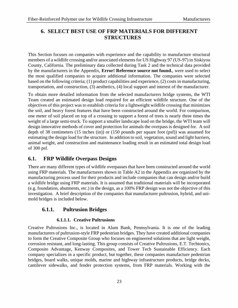
Figure 12: Example of FRP bridge made by Guardian Bridge Rapid Construction for a two lane road over a
creek, the bridge spans 15m; (Left) a triple-tee span being placed by a crane, (Right) all three spans placed on
top of an FRP abutment.
Guardian Bridge Rapid Construction has never built a wildlife overpass, but they entered a contest
hosted by ARC Solutions to develop a wildlife crossing using their innovative materials and
design. Their design was a lightweight and versatile structure (Figure 13). The bridge incorporated
modular construction with smaller bridge segments utilizing the tree canopy on the main span to
create multiple routes across the bridge. The bright red bridge was intended to be an iconic
structure for humans, signifying the crossing, the landscape and its non-human inhabitants, but is
unnoticeable to wildlife that cannot see the color red.

Fiber-Reinforced Polymer use for Wildlife Crossing Infrastructure Manufacturers
26
Figure 13: Design by Guardian Bridge Rapid Construction of a wildlife crossing structure for ARC
Solution’s design competition.
6.1.2.2. Hillman Composite Beams
Hillman Composite Beams (HillCB) is based out of Chicago, Illinois. Using decades of experience
in bridge design they have developed a structural girder that is an FRP exoskeloton surrounding
concrete and steel elements that support the compression and tension loads of a bridge (Figure 14).
Their hybrid composite beam (HCB) combines durable FRP materials with the low-cost and
functional advantages of concrete and steel that result in a cost competative, resilient bridge system
that benefits from an extended service life. The internal concrete arch is a parabolic curve that is
the proper funicular shape to eliminate flexure in the bridge span. In high seismic regions, the
reduced superstructure mass results in substructure costs being reduced by as much as 30%. With
years of proven field performance, their HCB is a revolutionay structural technology that
demonstrates HillCB’s commitment to provide a sustainable solution to deteriorating
infrastructure for future generations.
Figure 14: The schema of an HCB designed by Hillman Composite Beams.
Fiber-Reinforced Polymer use for Wildlife Crossing Infrastructure Manufacturers
27
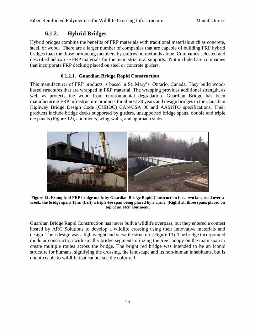
To date, HillCB has fabricated over 267 beams, all of which met or exceeded project specifications.
Currently the largest bridge span built is 106ft (Figure 15), but spans of 120ft or greater are
possible. Generally these beams are designed to be flat to accommodate the roadway profile, but
there is an upward camber to account for the dead load deflection. HillCB can over camber to some
degree for positive drainage, but this can also be done with the cross-slope of the bridge. It only
requires 1.5-2% slope in any direction to facilitate the drainage of the system. A flatter drainage
slope could have benefits of slowing down moisture loss in the soil for vegetation.
These beams are installed the same way as concrete beams and are typically surfaced with concrete
slabs. The company is currently looking at using FRP decking to put on top of the HCB that would
be able to support earth fill on top, but likely wont be suitable for traffic loads. The reinforced
concrete deck provides a safer riding surface for traffic and results in a substantial increase in the
flexural rigidity of the overall bridge system. HillCB has not performed a seismic analysis or
testing on the HCBs but have validated their panels for blast loads created by vapor cloud
explosions in petrochemical facilities. By virtue of their strength combined with low Young’s
Modulus, when compared to concrete and steel, HCB’s remain elastic during large displacement
events. HillCB suspects the same results when subjected to lateral seismic loading. They have
also done extensive testing on fatigue, serviceability, and strength of the beams, which includes
testing on thermal cycling, accelerated UV exposure, salt spray, and lateral impact.
Figure 15: Hillman Composite Beam’s HCB bridge near Lockwood, Missouri. The bridge consists of three
beams that span 106ft, are 5ft tall, 6ft wide, and support a 30ft 8in wide deck. (Left) Completed bridge.
(Right) One of the HCBs being transported on a truck.
HillCBs’ engineers typically provide a preliminnary design and share the design tools to allow for
the purchaser to experiment with their desired configuration. If certified engineering calculations
and plans are required, a Caltrans Professional Engineer (PE) will be required to prepare and/or
review the documents. HillCB prefers to have other engineers engaged in the design process. The
turn-around time to fabricate beams is about two months when the factory is in full production.
This time depends on the approval of shop drawings and the number of beams ordered.
The special provisions HillCB provided the WTI Team are consistent with their design process.
These provisions do not include the internal material properties of the concrete and steel inside the
HCB. Their design process starts by satisfying live load deflection criteria with a span/depth ratio

Fiber-Reinforced Polymer use for Wildlife Crossing Infrastructure Manufacturers
28
somewhere between Length (L)/18 and L/25, depending on design requirements and magnitude of
live loads. The ultimate bending capacity is then checked and is analogous to a reinforced concrete
beam. Shear is a little more complex because there is load sharing between the concrete rib and
FRP laminate webs that varies along the length of the beam.
6.1.2.3. Advanced Infrastructure Technologies
Advanced Infrastructure Technologies is based in Brewer, Maine, and works closely with the
University of Maine’s Advanced Structures and Composites Center where they do extensive
testing and design. Advanced Infrastructure Technologies (AIT) is an engineering and
manufacturing company that supplies advanced composite materials for bridges, while providing
low cost solutions to the aging and deteriorating transportation infrastructure industry. They have
received numerouse awards and recognition for their innovative and transformative products and
systems. By utilizing advanced composite materials to create non-corrosive products, AIT is an
industry pioneer and leader in transforming the bridge industry. They have developed two different
methods for creating FRP bridge spans that can be used for wildlife crossing infrastructure.
The concrete filled FRP tube (CFFT) bridge system developed by AIT is designed as an arched
culvert structure that can be used as an overpass. One example of a bridge that allows traffic to
travel over and under the CFFT bridge is shown Figure 16. The largest CFFT span built to date is
70ft, but AIT is currently testing spans over 100ft. Some of the bridges they have built have had
over 15ft of rise to them and are able to span a two-lane road.
Figure 16: CFFT bridge built by AIT in Augusta, Maine. The bridge uses 22, 15in diameter carbon-fiber
tubes to make a span of 54ft, is 55ft wide, and has a rise of 12ft above the concrete abutments to allow enough
clearance for traffic once they are placed on the pre-cast concrete foundation.
For bridge heights that exceed 16ft, the arch tubes are spliced at the apex in the field to avoid
overwidth transportation restrictions. However, the splice they have developed does not impact
the strength and durability of the CFFTs bridge. AIT uses the Federal Highway Association

Fiber-Reinforced Polymer use for Wildlife Crossing Infrastructure Manufacturers
29
(FHWA) Technical Manual for Design and Construction of Road Tunnels – Civil Elements to
design their CFFT bridge system because the structure was originally designed as a culvert-style
bridge to replace deteriorating infrastructure. A sesimic analysis would be required. Another
engineering consideration is foundation system required for the arched structure which includes
both vertical and horizontal components. The horizontal reaction needs to be supported by a
different foundation than a driven H-pile system, which has been identified by Caltrans engineers
as an economical foundation system for the area.
AIT offers a Mobile Composite Manufacturing Unit (MCMU). This equipment was developed as
a cost-effective manufacturing process that requires minimal plant/equipment to produce the
primary structural FRP tubes of the CFFT bridge. The MCMU is a self-containing 20ft standard
shipping container that is fully outfitted with all the necessary tools and equipment and is powered
by local energy grids. The unit includes a vacuum pump, air compressor, plugs, a generator, and
all equipment required for the vacuum infusion process. The manufacturing process requires a
separate supporting company that is capable of creating the plywood arch forms using a computer
numerical control (CNC) machine. The MCMU allows for local and scalable manufacturing at a
low capital cost. These manufacturing units can either be purchased or leased; it is normally not
cost efficient to ship the MCMU to a local site and train local labor, but for multiple projects it can
offset the cost of transportation of finished parts. The only restriction would be large, flat, staging
area near the construction-site, where the manufacturing takes place.
The second type of bridge developed by AIT, their newest composite bridge system, uses FRP
composite tub (CT) girders. The first bridge is scheduled to be constructed in during the second
half of 2020. The CT Girder is a long-life solution to traditional steel and concrete, medium span
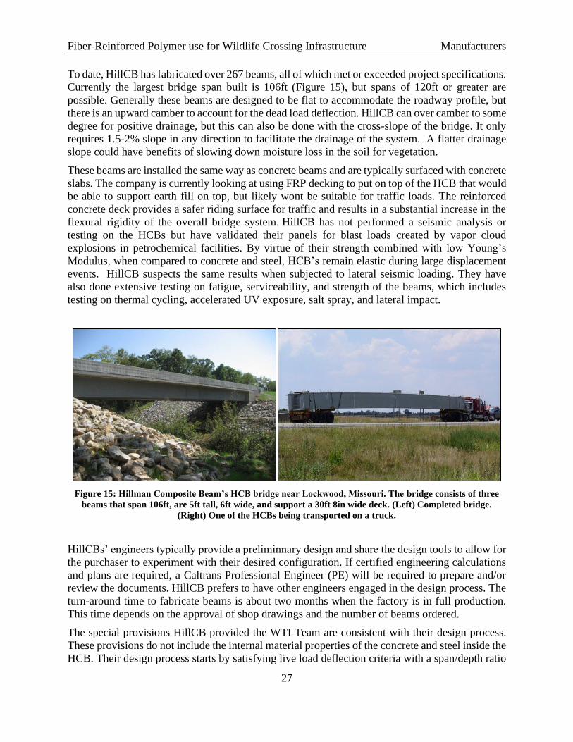
deck bridges at a low cost. The system consists of a lightweight FRP tub girder (Figure 17) that is
simply supported on standard foundations with a precast panel or cast-in-place concrete deck. The
girders use small foam inserts along the vertical sections to increase the width of the structure
while reducing weight. The girder is covered with a non-degradable cap (e.g. FRP, polyvinyl
chloride [PVC], or high-density polyethylene [HDPE]) that depends on the loading. If the form is
supporting a full 8-9in cast-in-place slab it would likely be made from 0.5in FRP sheet stock. If it
is only supporting a 4in partial-depth precast pour, a more economical material can be used because
it is only a form for temporary loading.
Fiber-Reinforced Polymer use for Wildlife Crossing Infrastructure Manufacturers
30
Figure 17: A section of a CT Girder made by AIT. Foam inserts can be seen in the vertical walls of the girder
to help reduce the weight.
The advantage of concrete decking is that it is a readily accessible material, relatively low cost and
provides excellent compressive strengths that optimizes the composite action and reduces overall
project costs. However, composite decking like the Atlas corrugated panels created by AIT can
likely be utilized on composite girders for smaller loads. An advantage to the AIT tub girder for
wildlife crossings is the potential to leave some of the CT girder uncovered so it can be filled with
soil and used for root propagation. A means of carrying the compressive forces and distributing
the soil forces to the girders would be a design consideration for an uncovered CT girder. This
could be achieved by a concrete deck with intermittent holes for root establishment. Likely a more
economical and simple solution would be to design the bridge for a 2-3ft deep soil layer over the
deck which would provide adequate soil for small vegetation.
AIT provides training and quality control on any products manufactured for their systems, whether
that is in-house manufacturing or subcontracting. The end product is a reflection of their company
and they take pride and care in every step of the process to ensure a quality part is delivered on
time.
AIT has done extensive durability testing on their composite structures using accepted criteria for
accelerated testing for environmental exposure. The test results exceed these critera and provide
evidence that their products will last 100 years, and possibly even longer. The bids from AIT
bridges have been competative when compared to other traditional construction methods. One
example is the bid for the Edmounds Bridge in Maine where costs and impact were compared to a
precast concrete alternative by Conspan (Figure 18). The CFFT bridge has a smaller footprint than
the precast concrete and therefore has less impact on the surrounding area. It is about 50% the cost
of the precast concrete and eliminates the need for staged construction and detours and reduces
environmental impacts.

Fiber-Reinforced Polymer use for Wildlife Crossing Infrastructure Manufacturers
31
Figure 18: Comparison between AIT’s CFFT bridge and Con/Span’s precast concrete designs.
6.1.3. Uni-mold Bridges
Uni-mold bridges are common across Europe with many qualified manufacturers. These
companies, however are limited in the geometry of their bridge designs because of the size
restrictions for shipping, wich is a concern for economy and sustainability. Because of the
transportation issues, the single manufacturer in North America capable of making a uni-mold
bridge large enough to be used in wildlife crossing infrastructure was selected for further
evaluation.
6.1.3.1. Orenco Composites
Orenco Composites is a FRP manufacturer headquartered on Interstate 5, north of Roseburg,
Oregon. Their location is conveniently located approximately 200 miles from the potential
crossing sites on US97. Orenco Composites is a division of Orenco Systems, Inc. and has been
manufacturing strong, water-resistant fiberglass products for more than 30 years. The company’s
engineers are nationally recognized experts in the fields of fiberglass product development and
manufacturing. Orenco builds FRP wastewater tanks, shelters, basins, enclousures for
telecommunications, and products used by utility, railroad, aviation, and food industries.
Recently Orenco Composites signed a contract with the FiberCore Europe to use their InfraCore®
Inside technology. The InfraCore® system is a proven cost-effective, easily scalable, strong,
lightweight, durable, damage-tolerant, maintenance free, load bearing and fail-safe FRP structure.
They achieve these characteristics by using foam blocks within the molds to combine the beneficial
properties of sandwich structures and multi-beam plates. InfraCore is a laminate technology which
enables the beneficial properties of classic sandwich structures (e.g. light weight, high stiffness,
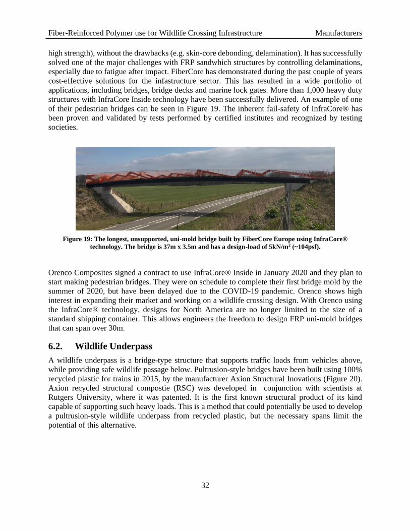
Fiber-Reinforced Polymer use for Wildlife Crossing Infrastructure Manufacturers
32
high strength), without the drawbacks (e.g. skin-core debonding, delamination). It has successfully
solved one of the major challenges with FRP sandwhich structures by controlling delaminations,
especially due to fatigue after impact. FiberCore has demonstrated during the past couple of years
cost-effective solutions for the infastructure sector. This has resulted in a wide portfolio of
applications, including bridges, bridge decks and marine lock gates. More than 1,000 heavy duty
structures with InfraCore Inside technology have been successfully delivered. An example of one
of their pedestrian bridges can be seen in Figure 19. The inherent fail-safety of InfraCore® has
been proven and validated by tests performed by certified institutes and recognized by testing
societies.
Figure 19: The longest, unsupported, uni-mold bridge built by FiberCore Europe using InfraCore®
technology. The bridge is 37m x 3.5m and has a design-load of 5kN/m2 (~104psf).
Orenco Composites signed a contract to use InfraCore® Inside in January 2020 and they plan to
start making pedestrian bridges. They were on schedule to complete their first bridge mold by the
summer of 2020, but have been delayed due to the COVID-19 pandemic. Orenco shows high
interest in expanding their market and working on a wildlife crossing design. With Orenco using
the InfraCore® technology, designs for North America are no longer limited to the size of a
standard shipping container. This allows engineers the freedom to design FRP uni-mold bridges
that can span over 30m.
6.2. Wildlife Underpass
A wildlife underpass is a bridge-type structure that supports traffic loads from vehicles above,
while providing safe wildlife passage below. Pultrusion-style bridges have been built using 100%
recycled plastic for trains in 2015, by the manufacturer Axion Structural Inovations (Figure 20).
Axion recycled structural compostie (RSC) was developed in conjunction with scientists at
Rutgers University, where it was patented. It is the first known structural product of its kind
capable of supporting such heavy loads. This is a method that could potentially be used to develop
a pultrusion-style wildlife underpass from recycled plastic, but the necessary spans limit the
potential of this alternative.

Fiber-Reinforced Polymer use for Wildlife Crossing Infrastructure Manufacturers
33
Figure 20: Pultrusion-style train bridge built from recycled plastic. Axion Structural Innovations created two
spans of 40ft and 80ft that can support 130-ton locomotives.
A uni-mold wildlife underpass manufactured by Orenco Composites is another option that may be
possible, but is limited by the lack of real-world applications and design standards in the US.
FiberCore has limited experience with bridge spans able to support traffic loads and included slow-
moving streets that do not have the same design requirements for high speed and large volume
traffic that exists along US-97. However, there has been research conducted that looked at FRP
uni-mold culvert structures through finite-element analysis with promissing results [64]. This may
be a method that is more acceptable in the future, but the WTI team has decided not to explore
uni-mold wildlife underpasses at this time. The FRP hybrid structures and manufacturers
mentioned above provide the most efficeient pathway toward the successful construction of an
FRP wildlife overpass.
6.3. Jump-outs, Fences, and Barriers
Jump-outs, fences, and barriers are design elements that help create a more effective wildlife
crossing. That is, they prevent wildlife from entering the roadway which decreases collisions, and
direct animals to the crossing structure with helps maintian wildlife movement and landscape
connectivity. Sound or light barriers help reduce traffic noise, artifical light from vehicles and
other traffic induced deterrents for wildlife to approach and cross the highway using the structure.
Fences or other types of barriers also keep animals from jumping off overpasses. They are also
essential design elements for bicycle and pedestrian bridges.
These design elements that improve the success of wildlife under- and overpasses do not require
the member sizes or the strength and stiffness demands of bridge structures. There are many
companies that are capable of making the FRP pultrusion (lumber) products required to build these

Fiber-Reinforced Polymer use for Wildlife Crossing Infrastructure Manufacturers
34
ancillary elements. The company below was selected for their proximity to the US-97 site,
available products, and their interest in wildlife crossing applications for their products.
6.3.1. American Plastic Lumber, Inc.
Although there are many manufactures of FRP pultrusion materials, American Plastic Lumber,
Inc., is based in Shingle Springs, California and is approximately 250 miles from the project’s US
Highway 97 crossing site.. They have been manufacturing maintenance-free recycled plastic
lumber products distributed throughout the world for nearly two decades. They offer a large
selection of colors, sizes, and grades available in the marketplace today. Applications include
boardwalks, docks, wharfs, decks, railings, and retainng walls. American Plastic Lumber is
capable of providing FRP products contributing to a successful wildlife crossing on US-97.
6.4. FRP Materials Available for the Project’s Design Tasks
After a broad review of FRP manufacturerers across North America, the WTI Team was able to
identify seven FRP manufactures with commercially available materials that would best be suited
or adapted for the structural component of the wildlife overpass for the project”s site on US
Highway 97 in Siskyou County, California (Table 4).
The WTI Team also identified numerous North American FRP pultrusion lumber manufacturers
with products that could be used for related crossing design elements (e.g., fence posts, decking,
sound barriers). The WTI Team elected to highlight just one, the closest manufacturer to the
crossing site, from the substantial list of FRP lumber producers in North America (Table 4).
In an upcoming task, the WTI Team will explore with Caltrans which of these materials to
incorporate into two or three preliminary structural designs. Each design will be based on using
different types of FRP materials.

Fiber-Reinforced Polymer use for Wildlife Crossing Infrastructure Manufacturers
35
Table 4: Selected FRP manufacturers best fit for designing and building wildlife crossing infrastructure.
Company Country Types of FRP structures Technical Data Available
Creative PultrusionsUSA
Trail bridges, decking, wall panels,
and structural beams
Material properties,
installation guide, design
Axion Structural
Innovations USA
Recycled plastic: boardwalks,
decking, support beams, pilings,
and foundation mats
Material properties
American Plastic
Lumber Inc.USA Recycled plastic lumber Material properties
Advanced
Infrastructure
Technologies
USABridge in a Backpack (CFFT),
composite tub girders
Maintenance, design,
installation
Hillman Composite
BeamsUSA Hybrid Composite Beams
Material properties of the
FRP shell
Guardian Bridge Rapid
ConstructionCanada
Decks, uni-mold bridges, and
hybrid structuresNA
Orenco CompositesUSA
Uni-mold bridges with InfraCore
technologyNA
FRP Companies Capable of Making Wildlife Crossing Infrastructure
Fiber-Reinforced Polymer use for Wildlife Crossing Infrastructure Conclusions
36
7. DISCUSSION
FRP technology supports modular construction design, variation in the way the fibers are laid out,
and different methods of fabrication. The dimensional constraints are due to the limitation of
handling larger product using existing bridge construction equipment and the transportation of
modular pieces on semi-trailer beds. The size of FPR structures is not restricted by the technology
itself but restricted by transportation logistics and the ability to manufacturer such large structures.
In principle, there is no limit to the dimensions of the FPR elements in a bridge design.
The ability for FRP to resist environmental degradation makes them a popular choice for marine
and chemical applications. The light weight and high strength composite are highly durable and
require no maintenance for their entire life cycle. The reduced maintenance and the accelerated
bridge construction method makes FRP materials a competitive product when compared to
conventional construction methods like concrete and steel.
The use of FRP composites to replace deteriorating pedestrian bridges in Europe has been proven
to be an effective strategy. There is now an increasing interest in North America because of FRPs
high strength to weight ratio, durability, and low maintenance cost. The initial higher costs can
mean that FRP structures may lose out in the current design/bid/build process that dominates the
current U.S. construction industry. Switching to design/build method may benefit the adoption of
FRP materials as owners of the structure has more freedom to experiment with innovative
materials and methods.
Increasing the acceptance of FRP materials in the North American transportation industry requires
a champion of the product. If the core state Departments of Transportation (DOT) start using these
materials on a more regular basis, other DOTs will be able to easily adopt the same methods and
strategies used. This will be helpful because there are infinite ways to design FRP bridges and
developing standards for a customizable structure can be challenging. This may require state DOTs
to adopt standards that focus on the performance of a structure so FRP manufacturers and engineers
are able to design a structure to those specifications.
There are many tests that have been done by FRP manufacturers and other researchers that look at
the structural properties of the materials and how they are affected by environmental conditions.
Although FRP composites are thoroughly understood, there is still no consensus about the full
potential of this material. The lack of standard procedures presents an obstacle for wider adopting
of FRP bridges in North America. The development and execution of strategic guidelines will fill
knowledge gaps and reduce the exposure to professional liability that is associated with not having
design standards. Sample design calculations and commentary for less common uses and solitary
FRP systems are especially needed. More FRP structures and guidelines are required to make the
product readily available at a reduced material cost.
There are examples of the three types of bridge construction techniques for FRP (e.g. pultrusion,
hybrid, and uni-mold) are currently installed along North American transportation networks.
However, there is nothing that is built with these methods that compare to the scale required to
build a wildlife overpass where the focal species is elk. This requires the WTI Team to explore the
limitations of the materials and work with the manufacturers to develop a structure that can span
US-97 and support the design-loads required on the surface of a wildlife overpass.

Fiber-Reinforced Polymer use for Wildlife Crossing Infrastructure References
37
8. REFERENCES
1. Huijser, M.P., et al., Wildlife-vehicle collision reduction study: Report to congress. 2007.
2. Sullivan, J.M., Trends and characteristics of animal-vehicle collisions in the United States.
Journal of safety research, 2011. 42(1): p. 9-16.
3. Braden, A., R. Lopez, and N. Silvy, Effectiveness of fencing, underpasses, and deer guards
in reducing Key deer mortality on the US 1 Corridor, Big Pine Key, Florida. 2005:
Department of Wildlife and Fisheries, Texas A & M University.
4. Clevenger, A.P., B. Chruszcz, and K.E. Gunson, Highway mitigation fencing reduces
wildlife-vehicle collisions. Wildlife Society Bulletin, 2001: p. 646-653.
5. Fermenga, D., et al. Cougar safe trek: leading the next generation of wildlife protection
along highways - the case of state route 241 wildlife fence in Orange County, California.
in International Confrence of Ecology and Transportation. 2017. Salt Lake City, UT.
6. Huijser, M., et al., Cost–benefit analyses of mitigation measures aimed at reducing
collisions with large ungulates in the United States and Canada: a decision support tool.
Ecology and Society, 2009. 14(2).
7. Rytwinski, T., et al., How effective is road mitigation at reducing road-kill? A meta-
analysis. PLoS one, 2016. 11(11): p. e0166941.
8. Ford, A.T., M. Barrueto, and A.P. Clevenger, Road mitigation is a demographic filter for
grizzly bears. Wildlife Society Bulletin, 2017. 41(4): p. 712-719.
9. Sawyer, H., P.A. Rodgers, and T. Hart, Pronghorn and mule deer use of underpasses and
overpasses along US Highway 191. Wildlife Society Bulletin, 2016. 40(2): p. 211-216.
10. Creech, T. and M. McClure, High-Risk Zones for Ungulate-Vehicle Collisions during
Montana’s Fall Migration Season.
11. Palu, S. and H. Mahmoud, Impact of climate change on the integrity of superstructure of
deteriorated U.S. bridges. PLoS ONE, 2019. 14(10).
12. Huntzinger, D.N. and T.D. Eatmon, A life-cycle assessment of Portland cement
manufacturing: comparing the traditional process with alternative technologies. Journal
of Cleaner Production, 2009. 17(7): p. 668-675.
13. Lister, N.-M., M. Brocki, and R. Ament, Integrated adaptive design for wildlife movement
under climate change. Frontiers in Ecology and the Environment, 2015. 13(9): p. 493-502.
14. Kemp, B. and D. Blowes, Concrete reinforcement and glass fiber reinforced polymer.
Queensland Roads Edition, 2011(11): p. 40-48.
15. Nijssen, R., Composite Materials: An Introduction. 2015: Inholland University of Applied
Sciences.
16. Gkaidatzis, R., Bio-based FRP structures: A pedestrian bridge in Schiphol Logistics Park.
2014.
17. Kim, Y.J., Use of Fiber-Reinforced Polymers in Highway Infrastructure. 2017.
Fiber-Reinforced Polymer use for Wildlife Crossing Infrastructure References
38
18. Creative Pultrusions Inc. Audubon Canyon Rance. 2019; Available from:
https://www.ettechtonics.com/project-gallery/audubon-canyon-ranch/.
19. Davalos, J.F., A. Chen, and P. Qiao, FRP deck and steel girder bridge systems: analysis
and design. 2013: CRC Press.
20. Smits, J., Fiber-Reinforced Polymer Bridge Design in the Netherlands: Architectural
Challenges toward Innovative, Sustainable, and Durable Bridges. Engineering, 2016. 2(4):
p. 518-527.
21. Sonnenschein, R., K. Gajdosova, and I. Holly, FRP Composites and their Using in the
Construction of Bridges. Procedia Engineering, 2016. 161: p. 477-482.
22. Demkowicz, M., Environmental durability of hybrid braided polymer matrix composites
for infrastructure applications. 2011.
23. Katangur, P., P.K. Patra, and S.B. Warner, Nanostructured ultraviolet resistant polymer
coatings. Polymer degradation and stability, 2006. 91(10): p. 2437-2442.
24. McConnell, V.P., Getting ducts in a row with corrosion-resistant FRP. Reinforced plastics,
2011. 55(4): p. 20-26.
25. Gaggino, R., Water-resistant panels made from recycled plastics and resin. Construction
and Building Materials, 2012. 35: p. 468-482.
26. WCED, S.W.S., World commission on environment and development. Our common future,
1987. 17: p. 1-91.
27. Zaman, A.U., et al., Sustainability and human health issues pertinent to fibre reinforced
polymer composites usage: A review. Journal of Reinforced Plastics and Composites, 2014.
33(11): p. 1069-1084.
28. Life Cycle Assessment Certified Professional, A life cycle assessment approach in
examining composite raw materials, steel and aluminum materials used in the
manufacturing of structural components. 2009: Strongwell Corporation.
29. Beetle Plastics FRP sustainability, green construction, and LEED. 2013.
30. Ilg, P., C. Hoehne, and E. Guenther, High-performance materials in infrastructure: a
review of applied life cycle costing and its drivers–the case of fiber-reinforced composites.
Journal of Cleaner Production, 2016. 112: p. 926-945.
31. Richardson, M. FRP composites provide a sustainable solution. 2019; Available from:
https://lifespanstructures.com/2019/02/12/frp-composites-provide-a-sustainable-solution/.
32. Oliveux, G., L.O. Dandy, and G.A. Leeke, Current status of recycling of fibre reinforced
polymers: Review of technologies, reuse and resulting properties. Progress in Materials
Science, 2015. 72: p. 61-99.
33. Job, S., Recycling glass fibre reinforced composites–history and progress. Reinforced
Plastics, 2013. 57(5): p. 19-23.
34. Bank, L.C. and A. Yazdanbakhsh, REUSE OF GLASS THERMOSET FRP COMPOSITES
IN THE CONSTRUCTION INDUSTRY–A GROWING OPPORTUNITY.
Fiber-Reinforced Polymer use for Wildlife Crossing Infrastructure References
39
35. Power, M. The promise and pitfalls of plastics in construction. Green Builder, 2018.
36. Shanti, R., et al., Degradation of ultra-high molecular weight poly (methyl methacrylate-
co-butyl acrylate-co-acrylic acid) under ultra violet irradiation. RSC Advances, 2017.
7(1): p. 112-120.
37. Wool, R. and X.S. Sun, Bio-based polymers and composites. 2011: Elsevier.
38. Chandra, V. and J.S. Kim, World's First Recycled Plastic Bridges, in ICSDC 2011:
Integrating Sustainability Practices in the Construction Industry. 2012. p. 585-593.
39. FiberCore Europe. InfraCore Inside technical datasheet. 2007; Available from:
http://www.fibercore-
europe.com/index.php?option=com_content&view=article&id=244&lang=en.
40. Kim, J.S. and V. Chandra. World's First Thermoplastic Bridges made of Recycled Plastics.
in IABSE Congress Report. 2012. International Association for Bridge and Structural
Engineering.
41. Yang, J. and L. Kalabuchova, Application of FRP materials in culvert road bridges: A
feasibility study with focus on mechanical behavior and life-cycle cost analysis in.
Department of Civil and Environmental Engineering, 2014.
42. Roylance, D., Mechanical properties of materials. Massachusetts Institute of Technology,
2008: p. 51-78.
43. Endruweit, A., F. Gommer, and A. Long, Stochastic analysis of fibre volume fraction and
permeability in fibre bundles with random filament arrangement. Composites Part A:
Applied Science and Manufacturing, 2013. 49: p. 109-118.
44. Fu, S.-Y., B. Lauke, and Y.-W. Mai, Science and Engineering of Short Fibre-Reinforced
Polymer Composites. 2019: Woodhead Publishing.
45. Frankhauser Jr, W., et al., Advances in Fiber-Reinforced Polymer (FRP) Composites in
Transportation Infrastructure. 2015.
46. Groenier, J.S., M. Eriksson, and S. Kosmalski, A Guide to Fiber-Reinforced Polymer Trail
Bridges. 2011, USDA Forest Service Technology and Development Program: Missoula,
MT.
47. Kamble, V.D., Optimization of thermoplastic pultrusion process using commingled fibers.
2008, University of Alabama at Birmingham.
48. Fiberline Composites. International award for innovative GRP footbridge. 2019; Available
from: https://fiberline.com/international-award-innovative-grp-footbridge.
49. CSIR. Resin transfer moulding process. 2018; Available from:
https://www.nal.res.in/en/techniques/resin-transfer-moulding-processes.
50. Fiberline Composites. German state highway agency installs GRP bridge. 2006 [cited
2019; Available from: https://fiberline.com/german-state-highway-agency-installs-grp-
bridge.
51. Hillman Composite Beams. Frequently asked questions about Hillman Composite Beams.
[cited 2020; Available from: http://www.hcbridge.com/faqs.
Fiber-Reinforced Polymer use for Wildlife Crossing Infrastructure References
40
52. Seoud, M.A. and J. Myers, IMPLEMENTATION OF HYBRID COMPOSITE BEAM (HCB)
BRIDGES IN MISSOURI, USA. 2013.
53. Hillman, J.R., Investigation of a hybrid-composite beam system. High Speed Rail IDEA
Program", Transportation Reserch Board of National Acadamies, Chicago, 2003.
54. Harris, D.K., J.M. Civitillo, and A. Gheitasi, Performance and behavior of hybrid
composite beam bridge in Virginia: Live load testing. Journal of Bridge Engineering, 2016.
21(6): p. 04016022.
55. Dagher, H.J., et al., Bending behavior of concrete-filled tubular FRP arches for bridge
structures. Construction and Building Materials, 2012. 37: p. 432-439.
56. Walton, H.J., Behavior of buried composite arch bridges. 2015, University of Maine. p.
330.
57. Walton, H.J., et al., Experimental Evaluation of Buried Arch Bridge Response to
Backfilling and Live Loading. Journal of Bridge Engineering, 2016. 21(9).
58. Ali, A.M. and R. Masmoudi, Flexural Strength and Behavior of Circular Sand-coated
Concrete-filled FRP Tubes under Cyclic Load. Special Publication, 2018. 327: p. 54.1-
54.18.
59. Abatiell, L. AIT composite arch bridge system. in The New Hampshire Joint Engineering
Societies Conference. 2018.
60. Milberg, E., New system from UMaine can build a bridge span in 3 days, in Composite
Manufacturing Magazine. 2018.
61. Advanced Infrastructure Technologies. AIT Products. 2019; Available from:
https://www.aitbridges.com/products.
62. AASHTO, LRFD Guide Specifications for Design of Concrete-Filled FRP Tubes for
Flexural and Axial Members. 2013, The American Association of State Highway and
Transportation Officials: Washington, D.C.
63. FiberCore Europe. Eindhoven Fauna bridge. 2019; Available from: https://www.fibercore-
europe.com/blog/project/eindhoven-wilhelminakanaal-faunabrug/.
64. Yang, J. and L. KALABUCHOVA, Application of FRP materials in Culvert Road Bridges-
A feasibility study with focus on mechanical behavior and lifecycle cost analysis. 2014.
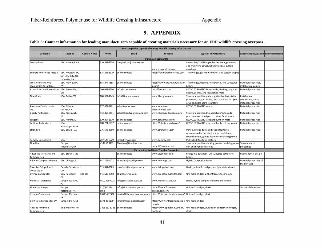
Fiber-Reinforced Polymer use for Wildlife Crossing Infrastructure Appendix
41
9. APPENDIX
Table 5: Contact information for leading manufacturers capable of creating materials necessary for an FRP wildlife crossing overpass.
Company Location Contact Name Phone Email Website Types of FRP structures Specification Available Figure Reference
Composicon USA: Hayward, CA 510-538-8556 [email protected]
www.composicon.com
Pedestrian/trail bridges, barrier walls, platforms
and walkways, structural fabrications, custom
moldings.
Bedford Reinforced Plastics USA: Houston, TX,
Salt Lake City, UT,
Lafayette, LA
814-285-3979 online contact https://bedfordreinforced.com Trail bridges, grated walkways, and custom shapes
Creative Pultrusions
(Composite Advantage)
USA: Alum Bank,
PA
888-274-7855 online contact https://www.creativepultrusion
s.com/
Trail bridges, decking, wall panels, and structural
beams
Material properties,
installation, design
Axion Structural Innovations USA: Zanesville,
OH
740-452-2500 [email protected] http://axionsi.com RECYCLED PLASTIC: boardwalks, decking, support
beams, pilings, and foundation mats
Material properties
FiberGrate USA: Dallas, TX 800-527-4043 [email protected] www.fibergrate.com Structural profiles, plates, grates, ladders, stairs,
platforms, custom molds, and sound barriers (STC
of 30 and class 1 fire retardant)
Installation,
soundscape, some
material properties
American Plastic Lumber
Inc.
USA: Shingle
Springs, CA
877-677-7701 [email protected] www.american-
plasticlumber.com
RECYCLED PLASTIC lumber Material properties
Liberty Pultrusions USA: Pittsburgh,
PA
412-466-8611 [email protected] www.libertypultrusions.com Structural profiles, threads/studs/nuts, rods,
precision mechined parts, custom fabrications
Material properties
Tangent USA: Aurora, IL 630-264-1110 online contact www.tangentusa.com RECYCLED PLASTIC structural lumber, mats Material properties
Bedford Technology USA:
Worthington,MN
800-721-9037 online contact https://plasticboards.com/ RECYCLED PLASTIC structural lumber, fence posts Material properties
Strongwell USA: Bristol, VA 276-645-8000 online contact www.strongwell.com Panels, bridge decks and superstructures,
retaining walls, nuts/bolts, structural shapes,
sound barriers, grates, foam-core building panels
Material properties
Kenway Composites USA: 207-622-6229 [email protected] www.kenway.com Pultruded structural profiles
Fiberline Europe:
Meddelfart, DK
45 70 13 7713 [email protected]
https://fiberline.com
Structural profiles, decking, pedestrian bridges, re-
bar, and hybrid structures
Some material
properties
Advanced Infrastructure
Technologies
USA: Brewer, ME online contact www.aitbridges.com Bridge in a Backpack (CFFT), hybrid composite
beams
Maintenance, design
Hillman Composite Beams USA: Chicago, IL 847-722-4072 [email protected] www.hcbridge.com Hybrid Composite Beams Material properties of
the FRP shell
Guardian Bridge Rapid
Construction
Canada: St. Marys,
ON
519-831-9989 [email protected] www.bridgedecks.ca Decks, uni-mold bridges, and hybrid structures
Orenco Composites USA: Roseburg,
OR
Eric Ball 541-580-2350 [email protected] www.orencocomposites.com Uni-mold bridges with InfraCore technology
Mostostal Warszawa Europe: Warsaw,
PL
48 22 250 7025 [email protected] www.mostostal.waw.pl Decks, hybrid composite beams and girders
FiberCore Europe Europe:
Rotterdam, NL
31 (0)10 476
5858
[email protected] https://www.fibercore-
europe.com/en/
Uni-mold bridges, decks Technical data sheet
Lifespan Structures Europe: Mitcham,
UK
0203 146 7332 [email protected] https://lifespanstructures.com/ Uni-mold bridges, decks
Delft Infra Composites BV Europe: Delft, NL 03 46 25 9290 [email protected] https://www.infracomposites.c
om/nl/
Uni-mold bridges
Applied Advanced
Technologies
Asia: Moscow, RU 7 495 261 30 33 online contact http://www.apatech.ru/index_
eng.html
Uni-mold bridges, pultrusion pedestrian bridges,
decks
Pultrusion Companies
FRP Companies Capable of Making Wildlife Crossing Infrastructure
Vacuum Assisted Resin Transfer Companies
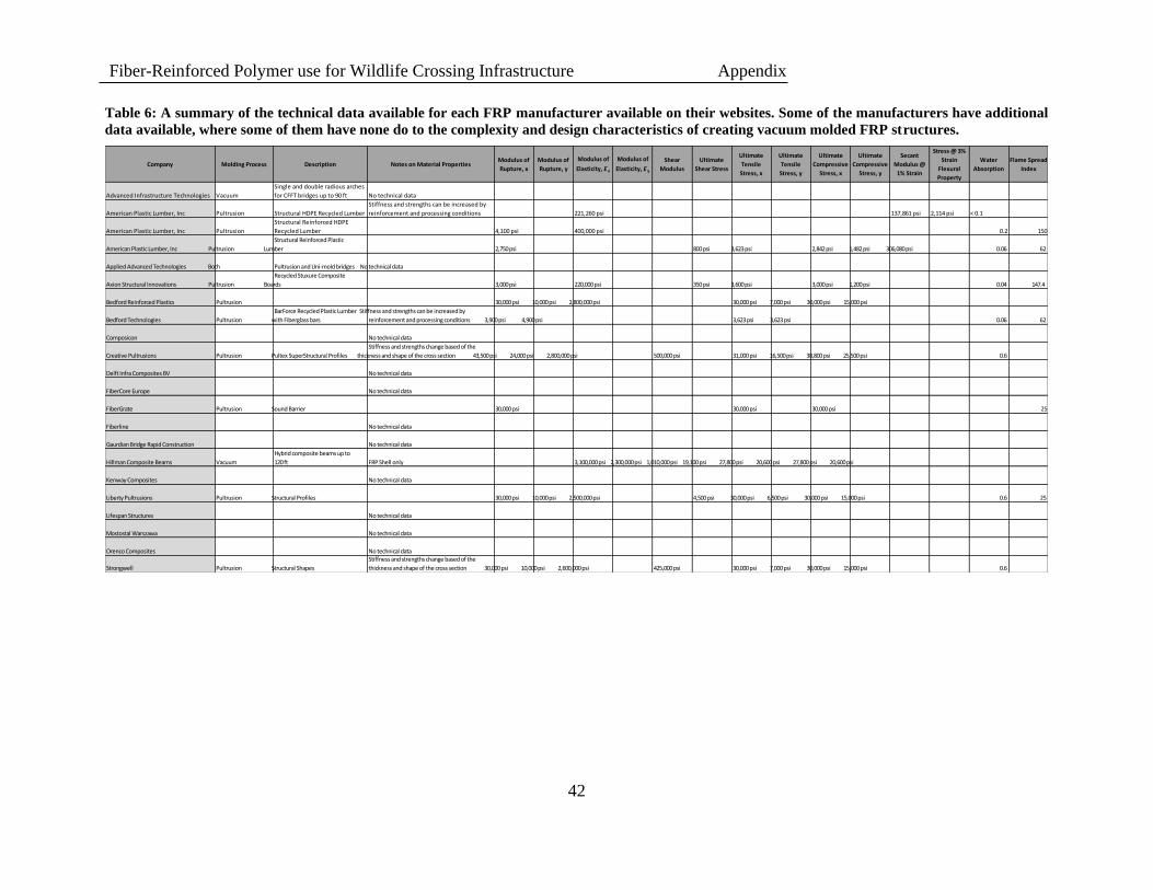
Fiber-Reinforced Polymer use for Wildlife Crossing Infrastructure Appendix
42
Table 6: A summary of the technical data available for each FRP manufacturer available on their websites. Some of the manufacturers have additional
data available, where some of them have none do to the complexity and design characteristics of creating vacuum molded FRP structures.
Stress @ 3% Ultimate Ultimate Ultimate Ultimate Secant
Modulus of Modulus of Modulus of Modulus of Shear Ultimate Strain Water Flame Spread Company Molding Process Description Notes on Material Properties Tensile Tensile Compressive Compressive Modulus @
Rupture, x Rupture, y Elasticity, E x Elasticity, E y Modulus Shear Stress Flexural Absorption IndexStress, x Stress, y Stress, x Stress, y 1% Strain
Property
Single and double radious arches
Advanced Infrastructure Technologies Vacuum for CFFT bridges up to 90 ft No technical data
Stiffness and strengths can be increased by
American Plastic Lumber, Inc Pultrusion Structural HDPE Recycled Lumber reinforcement and processing conditions 221,260 psi 137,861 psi 2,114 psi < 0.1
Structural Reinforced HDPE
American Plastic Lumber, Inc Pultrusion Recycled Lumber 4,100 psi 400,000 psi 0.2 150
Structural Reinforced Plastic
American Plastic Lumber, Inc Pultrusion Lumber 2,750 psi 800 psi 3,623 psi 2,842 psi 1,482 psi 306,080 psi 0.06 62
Applied Advanced Technologies Both Pultrusion and Uni-mold bridges No technical data
Recycled Stuxure Composite
Axion Structural Innovations Pultrusion Boards 3,000 psi 220,000 psi 350 psi 3,600 psi 3,000 psi 1,200 psi 0.04 147.4
Bedford Reinforced Plastics Pultrusion 30,000 psi 10,000 psi 2,800,000 psi 30,000 psi 7,000 psi 30,000 psi 15,000 psi
BarForce Recycled Plastic Lumber Stiffness and strengths can be increased by
Bedford Technologies Pultrusion with Fiberglass bars reinforcement and processing conditions 3,900 psi 4,900 psi 3,623 psi 3,623 psi 0.06 62
Composicon No technical data
Stiffness and strengths change based of the
Creative Pultrusions Pultrusion Pultex SuperStructural Profiles thickness and shape of the cross section 43,500 psi 24,000 psi 2,800,000 psi 500,000 psi 31,000 psi 16,500 psi 38,800 psi 25,500 psi 0.6
Delft Infra Composites BV No technical data
FiberCore Europe No technical data
FiberGrate Pultrusion Sound Barrier 30,000 psi 30,000 psi 30,000 psi 25
Fiberline No technical data
Gaurdian Bridge Rapid Construction No technical data
Hybrid composite beams up to
Hillman Composite Beams Vacuum 120 ft FRP Shell only 3,100,000 psi 2,300,000 psi 1,010,000 psi 19,100 psi 27,800 psi 20,600 psi 27,800 psi 20,600 psi
Kenway Composites No technical data
Liberty Pultrusions Pultrusion Structural Profiles 30,000 psi 10,000 psi 2,500,000 psi 4,500 psi 30,000 psi 6,500 psi 30,000 psi 15,000 psi 0.6 25
Lifespan Structures No technical data
Mostostal Warszawa No technical data
Orenco Composites No technical dataStiffness and strengths change based of the
Strongwell Pultrusion Structural Shapes thickness and shape of the cross section 30,000 psi 10,000 psi 2,600,000 psi 425,000 psi 30,000 psi 7,000 psi 30,000 psi 15,000 psi 0.6
Nevada Department of Transportation Kristina L. Swallow, P.E. Director
Ken Chambers, Research Division Chief (775) 888-7220
[email protected] 1263 South Stewart Street
Carson City, Nevada 89712
Top Related