


Languages
Pages
Legal


ZC
ATO
GC
LAM
PE
NG
15U
K
ELESA (UK) LTD26 Moorlands Estate
MetheringhamLincolnshire LN4 3HX
phone +44 (0) 1526 322670fax +44 (0) 1526 322669
www.elesa.com
Toggle clamps

Photographic index 2
The ELESA full product range 5
Product data sheets 6-61
Numerical index 62
Alphabetical index 63
page
GENERAL INDEX
Toggle clamps

2
Pho
togr
aphi
c in
dex
MVA.Vertical toggle clampswith folded baseSteelStainless steel
page 6
MVB.Vertical toggle clampswith straight baseSteelStainless steel
page 8
MVC.Vertical toggle clampswith double baseSteel
page 10
MVD.Vertical toggle clampswith double baseSteel
page 11
MPB.Vertical toggle clampsHeavy-duty seriesSteel
page 12
MVA.LVertical toggle clampswith folded baseLong life seriesSteel
page 13
MVB.LVertical toggle clampswith straight baseLong life seriesSteel
page 14
MGA.LToggle-joint mechanismsSteel
page 15
MGB.LToggle-joint mechanismsSteel
page 16
MGC.LToggle-joint mechanismsSteel
page 17
ALL.Accessoriesfor toggle-joint mechanismsSteel
page 18
MOC.Horizontal toggle clampswith folded baseSteelStainless steel
page 19
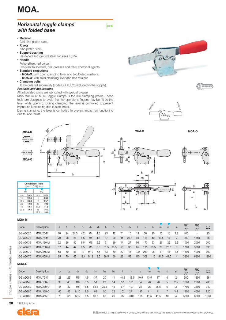
MOA.Horizontal toggle clampswith folded baseSteel
page 20
MOA-SSTHorizontal toggle clampswith folded baseStainless steel
page 21
MOB.Horizontal toggle clampswith straight baseSteel
page 22
MOB-SSTHorizontal toggle clampswith straight baseStainless steel
page 23
MLA.Push-pull clampsSteel
page 24
MLB.Push-pull clampsSteel
page 25
MFA.Push-pull clampsSteel
page 26
MFC.Push-pull clampsSteel
page 27
PHOTOGRAPHIC INDEX
Toggle clamps
Vertical series
Long life series
Horizontal series
Push-pull clamps

3
Pho
togr
aphi
c in
dex
MFE.Push-pull clampsSteel
page 28
MFE-SSTPush-pull clampsStainless steel
page 29
MTB.Latch clamps with safety stopSteel
page 30
MTB-SSTLatch clamps with safety stopStainless steel
page 32
MTC.Latch clampsSteel
page 34
MTC-SSTLatch clampsStainless steel
page 35
MTD.Latch clampsSteel
page 36
MTD-SSTLatch clampsStainless steel
page 37
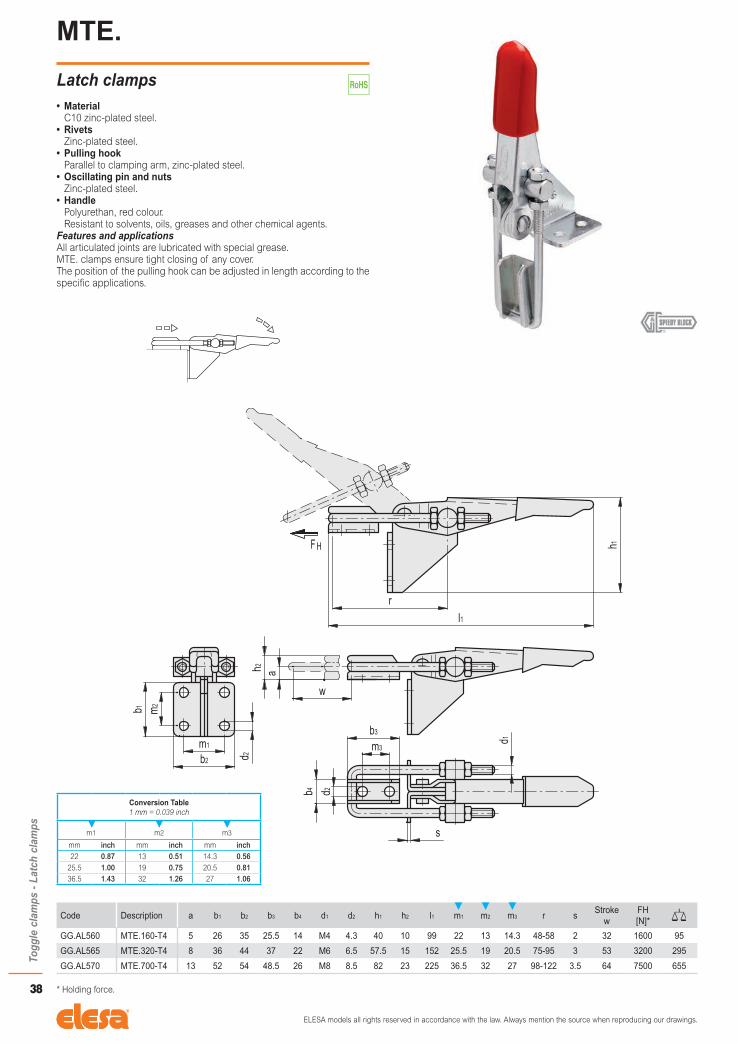
MTE.Latch clampsSteel
page 38
MTA.Latch clampsSteel
page 39
MTP.Latch clampsHeavy-duty seriesSteel
page 40
MTP-SSTLatch clampsHeavy-duty seriesStainless steel
page 41
MTS.Weldable latch clampsHeavy-duty seriesSteel
page 42
MTS-SSTWeldable latch clampsHeavy-duty seriesStainless steel
page 43
MTL.Latch clamps with safety deviceHeavy-duty seriesSteel
page 44
MTP-DLatch clampsHeavy-duty seriesSteel
page 45
MTS-DWeldable latch clampsHeavy-duty seriesSteel
page 46
MTR.Weldable latch clampsSteel
page 47
MVA-RVertical toggle clampswith folded baseSteel
page 48
MOA-RHorizontal toggle clampswith folded baseSteel
page 49
MCRWeldable latch clampsSteel
page 50
PFA.Pneumatic clamps with push leverSteel
page 51
PVA.Pneumatic clampsSteel
page 52
PPC.Pneumatic clampsHeavy-duty seriesSteel
page 53
Latch clamps
Series for high temperatures
Pneumatic clamps

4
Pho
togr
aphi
c in
dex
PVC.Pneumatic clampswith toggle-joint supportSteel
page 54
PPD.Pneumatic clampsHeavy-duty seriesSteel
page 55
PSW.Limit switcheswith holding bracket
page 56
SAH.Clamping boltsSteel
page 57
SAH-SSTClamping boltsStainless steel
page 57
SRH.Clamping boltsSteel
page 58
SRH-SSTClamping boltsStainless steel
page 58
SSH.Clamping bolts with springSteel
page 59
SHH.Clamping boltsSteel
page 60
SHH-SST.Clamping boltsStainless steel
page 60
NCH.Caps for clamping boltsNeoprene
page 61
NCN.Caps for clamping bolts with threaded insertNeoprene
page 61
Accessories
Toggle joints mechanism features
Thanks to the toggle action principle, quick action clamps offer various advantages:
• Since the clamping arm moves fully away from the working area it leaves unimpeded access to the
fixture, which can therefore be taken away or placed very easily (fig. 1).
• A slight movement of the control lever brings the clamping arm near to the work piece.
• The position of the three pivot points (fi g. 2) clearly shows that the force exerted on the clamping arm is
monitored by the control lever (fi g.3). The maximun clamping force (Fs) is achieved when the three pivots
are aligned (dead point of the lever).
The intensity of the force Fs exerted on the tool depends upon:
- the force applied to the handle;
- the position of the clamping bolt in the hold down bar.
The manual force applied by the operator cannot be calculated, so the Fs values reported in the tables
refer to pneumatic devices. In the most effective position (fi g. 3) the clamping balance is rather unstable,
as opposing forces may act on the hold-down bar thus opening the clamp..
• When in the closed position the dead point is exceeded slightly (fi g. 4), and the clamping lever is in an
over-center locked position with a steady and irreversible holding capacity.
The force the clamp may absorb in the closed position with no permanent deformation is called the holding
force (Fh). Its amount is specifi c to each toggle clamp and varies according to clamp size and form.
Forces are calculated in daN (deca Newton) = 10N (Newton) = 1Kg weight.
fig. 1 fig. 2
fig. 3 fig. 4

The ELESAfull product range
1. OPERATING ELEMENTS Spoked handwheels Solid handwheels Arm handwheels Crank handles
2. CLAMPING KNOBS Lobe knobs Grip knobs
3. CLAMPING LEVERS Adjustable handles Lever handles
4. LIFT & PULL HANDLES Bridge handles Flush pull handles Tubular handles
5. FIXED & REVOLVING HANDLES Fixed handles Revolving handles Fold-away handles
6. CONTROL ELEMENTS Control knobs Control levers
7. ROTARY CONTROLS Gravity indicators Positive drive indicators Direct drive indicators Handwheels with indicator
8. INDEXING AND POSITIONING ELEMENTS Indexing plungers Lock pins Spring plungers
9. MACHINE ELEMENTS Grub-screws, thrust pads, rings, washers Cam locking levers Joints, vibration-damping elements Ball transfer units Magnets
10. LEVELLING ELEMENTS AND SUPPORTS Levelling elements Bearing end caps Supports and guides Connecting clamps
11. HINGES AND CONNECTIONS Plastic hinges Steel hinges Connection angles
12. LATCHES Latches with handle Latches with key Hook clamps Toggle clamps
13. ACCESSORIES FOR HYDRAULIC SYSTEMS Plugs Breather caps Level indicators Column level indicators
14. CASTORS AND WHEELS Injected polyurethane wheels Technopolymer wheels Rubber wheels
15. HANDLES FOR SPECIAL APPLICATIONS Handles for instruments and equipment Handles for machines and protections Stainless steel handles CLEAN handles for medical and food processing equipment
16. CONNECTING CLAMPS Connectiong clamps for tubes Tubes and accessories Linear actuators and clamp connectors

ELESA models all rights reserved in accordance with the law. Always mention the source when reproducing our drawings.
6
Togg
le c
lam
ps -
Vert
ical
ser
ies
MVA.
Vertical toggle clamps with folded base• Standard executions
- MVA-A: C10 zinc-plated steel, zinc-plated steel rivets.Open clamping lever and two folded washers.
- MVA-E: C10 zinc-plated steel, zinc-plated steel rivets.Solid clamping lever and bolt retainer.
- MVA-AX: AISI 304 stainless steel.Open clamping lever and two folded washers.
- MVA-EX: AISI 304 stainless steel.Solid clamping lever and bolt retainer.
• Support bushingGround and hardened steel.
• HandlePolyurethan, red colour.Resistant to solvents, oils, greases and other chemical agents.
• Clamping boltsTo be ordered separately.
Features and applicationsAll articulated joints are lubricated with special grease.During clamping, the lever is controlled to prevent impact on functioning due to side thrust.The new geometry of MVA vertical toggle clamps gives them additional strength, their lifespan is significantly increased with the addition of hardened steel support bushings as well as several other forms of reinforcement.Slotted assembly holes for applications in inches.
FH1 FH2
90°
h1
l
l1
s1d1
h2h3
al2
m2 b2
m1
b1
s
MVA-A
Code Description a b1 b2 b3 d1 d2 h1 h2 h3 l l1 l2 m1 m2 s1FH1 [N]*
FH2 [N]*
GG.AA520 MVA.75-A 20 29 34 5.2 M5 4.5 98 20.5 11 37.5 66.5 31.5 15-16 24 2 750 1600 98
GG.AA530 MVA.130-A 28 35 42 6.2 M6 5.5 142 28 16 50 85 42 12.5-19 27-29 2.5 1050 1750 230
GG.AA540 MVA.230-A 40 43 45 8.5 M8 6.5 168 33.5 18 67.5 110.5 58 19-20 32 3 2000 3200 380
GG.AA550 MVA.330-A 43 50 65 10.5 M10 8.5 195 43 22 79 129 76 29-32 45-46 3.5 2400 4000 604
GG.AA560 MVA.430-A 64 58 65 12.5 M12 8.5 247 55.5 26 106 164 104 32 45 4 2800 5000 1100
GG.AA570 MVA.530-A 90 80 95 12.5 M12 12.5 303 84.5 32 143 223 144 50-51 70 7 4500 8750 2110
* Holding force.
Conversion Table1 mm = 0.039 inch
m1 m2
mm inch mm inch15-16 0.59-0.63 24 0.94
12.5-19 0.49-0.75 27-29 1.06-1.1419-20 0.75-0.79 32 1.2629-32 1.14-1.26 45-46 1.77-1.81
32 1.26 45 1.7750-51 1.97-2.00 70 2.75

ELESA models all rights reserved in accordance with the law. Always mention the source when reproducing our drawings.
7
Togg
le c
lam
ps -
Vert
ical
ser
ies
MVA-E
Code Description b1 b2 d1 d2 h1 h2 h3 l l1 m1 m2 s s1FH1 [N]*
FH2 [N]*
GG.AA524 MVA.75-E 29 34 M5 4.5 98 20.5 11 38 67 15-16 24 4 2 750 1600 100
GG.AA534 MVA.130-E 35 42 M6 5.5 142 28 16 51 86 12.5-19 27-29 5 2.5 1050 1750 235
GG.AA544 MVA.230-E 43 45 M8 6.5 168 33.5 18 69 112 19-20 32 6 3 2000 3200 390
GG.AA554 MVA.330-E 50 65 M10 8.5 195 42 20 80.5 130.5 29-32 45-46 7 3.5 2400 4000 604
GG.AA564 MVA.430-E 58 65 M12 8.5 247 55.5 26 108 166 32 45 10 4 2800 5000 1100
GG.AA574 MVA.530-E 80 95 M12 12.5 303 84.5 32 145 225 50-51 70 10 7 4500 8750 2110
MVA-AX
Code Description a b1 b2 b3 d1 d2 h1 h2 h3 l l1 l2 m1 m2 s1FH1 [N]*
FH2 [N]*
GG.AS095 MVA.75-AX 20 29 34 5.2 M5 4.5 98 20.5 11 37.5 66.5 31.5 15-16 24 2 750 1600 98
GG.AS150 MVA.130-AX 28 35 42 6.5 M6 5.5 142 28 16 50 85 42 12.5-19 27-29 2.5 1050 1750 230
GG.AS180 MVA.230-AX 40 43 45 8.5 M8 6.5 168 33.5 18 67.5 110.5 58 19-20 32 3 2000 3200 380
MVA-EX
Code Description b1 b2 d1 d2 h1 h2 h3 l l1 m1 m2 s s1FH1 [N]*
FH2 [N]*
GG.AS105 MVA.75-EX 29 34 M5 4.5 98 20.5 11 38 67 15-16 24 4 2 750 1600 100
GG.AS160 MVA.130-EX 35 42 M6 5.5 142 28 16 51 86 12.5-19 27-29 5 2.5 1050 1750 235
GG.AS190 MVA.230-EX 43 45 M8 6.5 168 33.5 18 69 112 19-20 32 6 3 2000 3200 390
* Holding force.
FH1 FH2
90°
h1
l
l1
s1
d1
h2h3
al2
m2 b2
m1
b1
s
Conversion Table1 mm = 0.039 inch
m1 m2
mm inch mm inch15-16 0.59-0.63 24 0.94
12.5-19 0.49-0.75 27-29 1.06-1.1419-20 0.75-0.79 32 1.2629-32 1.14-1.26 45-46 1.77-1.81
32 1.26 45 1.7750-51 1.97-2.00 70 2.75

ELESA models all rights reserved in accordance with the law. Always mention the source when reproducing our drawings.
8
Togg
le c
lam
ps -
Vert
ical
ser
ies
MVB.
Vertical toggle clamps with straight base• Standard executions
- MVB-B: C10 zinc-plated steel, zinc-plated steel rivets.Open clamping lever and two folded washers. - MVB-F: C10 zinc-plated steel, zinc-plated steel rivets.Solid clamping lever and bolt retainer.
- MVB-BX: AISI 304 stainless steel.Open clamping lever and two folded washers.
- MVB-FX: AISI 304 stainless steel.Solid clamping lever and bolt retainer.
• Support bushingGround and hardened steel.
• HandlePolyurethan, red colour.Resistant to solvents, oils, greases and other chemical agents.
• Clamping boltsTo be ordered separately.
Features and applicationsAll articulated joints are lubricated with special grease.During clamping, the lever is controlled to prevent impact on functioning due to side thrust.The new geometry of MVB vertical toggle clamps gives them additional strength, their lifespan is significantly increased with the addition of hardened steel support bushings as well as several other forms of reinforcement.Slotted assembly holes for applications in inches.
MVB-B
Code Description a b1 b2 b3 b4 d1 d2 h1 h2 h3 l l1 l2 m1 m2FH1 [N]*
FH2 [N]*
GG.AA522 MVB.75-B 20 29 8 5.2 16 M5 4.5 109.5 27 11 37.5 66.5 31.5 15-16 5 750 1600 98
GG.AA532 MVB.130-B 28 35 10 6.2 20 M6 5.5 156 35 16 50 85 42 12.5-19 6.5 1050 1750 230
GG.AA542 MVB.230-B 40 43 12 8.5 23 M8 6.5 183 41.5 18 67.5 110.5 58 19-20 6.5 2000 3520 380
GG.AA552 MVB.330-B 43 50 14 10.5 25 M10 8.5 218 56.5 22 79 129 76 29-32 9.5 2400 4000 620
GG.AA562 MVB.430-B 64 58 18 12.5 34 M12 8.5 267.5 67.5 26 106 164 104 32 10 2800 5000 1110
GG.AA572 MVB.530-B 90 77 18 12.5 34 M12 12.5 337 105 32 146 223 144 50-51 12.5 4500 8750 1920
* Holding force.
Conversion Table1 mm = 0.039 inch
m1
mm inch15-16 0.59-0.63
12.5-19 0.49-0.7519-20 0.75-0.7929-32 1.14-1.26
32 1.2650-51 1.97-2.00

ELESA models all rights reserved in accordance with the law. Always mention the source when reproducing our drawings.
9
Togg
le c
lam
ps -
Vert
ical
ser
ies
MVB-F
Code Description b1 b2 b4 d1 d2 h1 h2 h3 l l1 m1 m2 sFH1 [N]*
FH2 [N]*
GG.AA526 MVB.75-F 29 8 16 M5 4.5 109.5 27 11 38 67 15-16 5 4 750 1160 100
GG.AA536 MVB.130-F 35 10 20 M6 5.5 156 35 16 51 86 12.5-19 6.5 5 1050 1750 235
GG.AA546 MVB.230-F 43 12 23 M8 6.5 183 41.5 18 69 112 19-20 6.5 6 2000 3200 390
GG.AA556 MVB.330-F 50 14 25 M10 8.5 218 56.5 22 80.5 130.5 29-32 9.5 7 2400 4000 620
GG.AA566 MVB.430-F 58 18 34 M12 8.5 267.5 67.5 26 108 166 32 10 10 2800 5000 1110
GG.AA576 MVB.530-F 77 18 34 M12 12.5 337 105 32 148 225 50-51 12.5 10 4500 8000 1920
MVB-BX
Code Description a b1 b2 b3 b4 d1 d2 h1 h2 h3 l l1 l2 m1 m2FH1 [N]*
FH2 [N]*
GG.AS100 MVB.75-BX 20 29 8 5.2 16 M5 4.5 109.5 27 11 37.5 66.5 31.5 15-16 5 750 1600 98
GG.AS155 MVB.130-BX 28 35 10 6.2 20 M6 5.5 156 35 16 50 85 42 12.5-19 6.5 1050 1750 230
GG.AS185 MVB.230-BX 40 43 12 8.5 23 M8 6.5 183 41.5 18 67.5 110.5 58 19-20 6.5 2000 3200 380
MVB-FX
Code Description b1 b2 b4 d1 d2 h1 h2 h3 l l1 m1 m2 sFH1 [N]*
FH2 [N]*
GG.AS110 MVB.75-FX 29 8 16 M5 4.5 109.5 27 11 38 67 15-16 5 4 750 1600 100
GG.AS165 MVB.130-FX 35 10 20 M6 5.5 156 35 16 51 86 12.5-19 6.5 5 1050 1750 235
GG.AS195 MVB.230-FX 43 12 23 M8 6.5 183 41.5 18 69 112 19-20 6.5 6 2000 3200 390
* Holding force.
Conversion Table1 mm = 0.039 inch
m1
mm inch15-16 0.59-0.63
12.5-19 0.49-0.7519-20 0.75-0.7929-32 1.14-1.26
32 1.2650-51 1.97-2.00

ELESA models all rights reserved in accordance with the law. Always mention the source when reproducing our drawings.
10
Togg
le c
lam
ps -
Vert
ical
ser
ies
MVC.
Vertical toggle clamps with double base• Material
C10 zinc-plated steel.• Rivets
Zinc-plated steel.• Handle
Polyurethan, red colour.Resistant to solvents, oils, greases and other chemical agents.
• Standard executions - MVC-AV: with open clamping lever and two folded washers. - MVC-EV: with solid clamping lever and retainer for welding.
• Clamping boltsTo be ordered separately.
Features and applicationsAll articulated joints are lubricated with special grease.MVC. toggle clamps can be mounted on two different surfaces and occupy a limited space for clamping as lever and arm move in two opposite directions.
MVC-AV
Code Description a b1 b2 b3 b4 d1 d2 h1 h2 h3 h4 l l1 l2 m1 m2 m3 r s1FH1 [N]*
FH2 [N]*
GG.AA220 MVC.200-AV 34 32 38 32 8.5 M8 6.5 154 74 17 34 58.5 157 59 16 26 16 96 3 1200 2400 430
GG.AA320 MVC.300-AV 42 45 48 48 10.4 M10 8.5 198 108 20 41 76 193 74 28 30 30 122 3 1900 2800 800
MVC-EV
Code Description b1 b2 b3 d1 d2 h1 h2 h3 l l1 l3 m1 m2 m3 r s s1FH1 [N]*
FH2 [N]*
GG.AA225 MVC.200-EV 32 38 32 M8 6.5 154 74 17 60.5 159 76 16 26 16 96 6 3 1200 2400 430
GG.AA325 MVC.300-EV 45 48 48 M10 8.5 198 108 20 78 195 95 28 30 30 122 8 3 1900 2800 800
* Holding force.
Conversion Table 1 mm = 0.039 inch
m1 m2 m3
mm inch mm inch mm inch16 0.63 26 1.02 16 0.6328 1.10 30 1.18 30 1.18

ELESA models all rights reserved in accordance with the law. Always mention the source when reproducing our drawings.
11
Togg
le c
lam
ps -
Vert
ical
ser
ies
MVD.
Vertical toggle clamps with double base• Material
C10 zinc-plated steel.• Rivets
Zinc-plated steel.• Handle
Polyurethan, red colour.Resistant to solvents, oils, greases and other chemical agents.
• Standard executions - MVD-AVF: with open clamping lever and two folded retainers. - MVD-EVF: with solid clamping lever and retainer for welding.
• Clamping boltsTo be ordered separately.
Features and applicationsAll articulated joints are lubricated with special grease.MVD. toggle clamps can be mounted on two different surfaces and occupy a limited space for clamping as lever and arm move in two opposite directions.
MVD-AVF
Code Description a b1 b2 b3 b4 d1 d2 h1 h2 h3 h4 l l1 l2 l3 m1 m2 m3 r s1FH1 [N]*
FH2 [N]*
GG.AA221 MVD.200-AVF 36 32 38 32 8.5 M8 6.5 203 77 17 34 59 103 61 - 16 26 16 97 3 1600 2500 390
GG.AA321 MVD.300-AVF 50 45 48 48 10.3 M10 8.5 258 105 20 41 76 130 - 85 28 30 30 121 3 2400 3700 680
MVD-EVF
Code Description b1 b2 b3 d1 d2 h1 h2 h3 l l1 l2 l3 m1 m2 m3 r s s1FH1 [N]*
FH2 [N]*
GG.AA226 MVD.200-EVF 32 38 32 M8 6.5 203 77 17 61 105 61 - 16 26 16 97 6 3 1600 2500 400
GG.AA326 MVD.300-EVF 45 48 48 M10 8.5 258 105 20 77.5 132 - 100 28 30 30 123 8 3 2400 3700 690
* Holding force.
Conversion Table 1 mm = 0.039 inch
m1 m2 m3
mm inch mm inch mm inch16 0.63 26 1.02 16 0.6328 1.10 30 1.18 30 1.18
ELESA models all rights reserved in accordance with the law. Always mention the source when reproducing our drawings.
12
Togg
le c
lam
ps -
Vert
ical
ser
ies
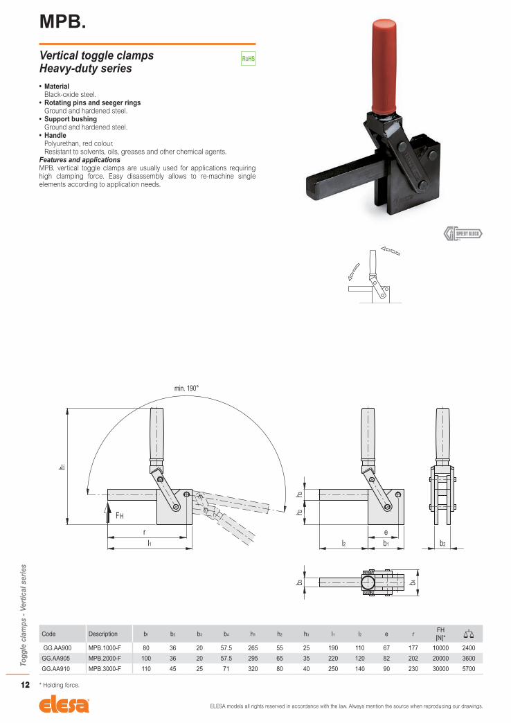
MPB.
Vertical toggle clamps Heavy-duty series• Material
Black-oxide steel.• Rotating pins and seeger rings
Ground and hardened steel.• Support bushing
Ground and hardened steel.• Handle
Polyurethan, red colour.Resistant to solvents, oils, greases and other chemical agents.
Features and applicationsMPB. vertical toggle clamps are usually used for applications requiring high clamping force. Easy disassembly allows to re-machine single elements according to application needs.
Code Description b1 b2 b3 b4 h1 h2 h3 l1 l2 e rFH [N]*
GG.AA900 MPB.1000-F 80 36 20 57.5 265 55 25 190 110 67 177 10000 2400
GG.AA905 MPB.2000-F 100 36 20 57.5 295 65 35 220 120 82 202 20000 3600
GG.AA910 MPB.3000-F 110 45 25 71 320 80 40 250 140 90 230 30000 5700
* Holding force.

ELESA models all rights reserved in accordance with the law. Always mention the source when reproducing our drawings.
13
Togg
le c
lam
ps -
Long
life
ser
ies
MVA.L
Vertical toggle clamps with folded base Long life series• Material
Black-oxide steel.• Rotating pins
Hardened, black-oxide and ground steel.• Support bushing
Hardened, black-oxide and ground steel.• Adjusting screw and nut
Zinc-plated steel.• Handle
Polyurethan, red colour.Resistant to solvents, oils, greases and other chemical agents.
• Standard executions - MVA.LLA: with open clamping lever and two folded washers. - MVA.LLE: with solid clamping lever.
• Clamping boltsTo be ordered separately.
Features and applicationsAll articulated joints are lubricated with special grease.During clamping, the lever is controlled to prevent impact on functioning due to side thrust.High-quality materials make Long Life series toggle clamps suitable for medium to heavy loads on welding jigs, carpentry works, moulds and in general whenever high clamping torque and repetitive movements are required.Certified for 1.000.000 cycles.
MVA.LLA
Code Description a b1 b2 b3 d1 d2 h1 h2 h3 h4 l l1 l2 m1 m2 r1 s1FH1 [N]*
FH2 [N]*
GG.AA600 MVA.LLA01 32 36 48 6 M6 6.5 136.5 30 16 27 49 91 51 20 32 77 3.5 2200 2800 330
GG.AA630 MVA.LLA02 34 54 65 10 M10 8.5 215 50 24 45 64 129.5 66 30 45 107 5 4400 8200 1200
MVA.LLE
Code Description b1 b2 d1 d2 h1 h2 h3 l l1 l3 m1 m2 r1 s s1FH1 [N]*
FH2 [N]*
GG.AA610 MVA.LLE01 36 48 M6 6.5 136.5 30 16 44 86 46 20 32 77 6 3.5 2200 2800 325
GG.AA640 MVA.LLE02 54 65 M10 8.5 215 50 24 64 129.5 66 30 45 107 10 5 4400 8200 1200
GG.AA660 MVA.LLE03 75 75 M12 10.5 280 67 30 74 161 72 55 55 - 12 6 8500 - 2200
GG.AA681 MVA.LLE05 90 100 M16 12.5 330 76.5 8 96 203 - 65 65 - 16 - 15400 - 4470
* Holding force.
Conversion Table1 mm = 0.039 inch
m1 m2
mm inch mm inch20 0.79 32 1.2630 1.18 45 1.7755 2.16 55 2.1665 2.56 65 2.56

ELESA models all rights reserved in accordance with the law. Always mention the source when reproducing our drawings.
14
Togg
le c
lam
ps -
Long
life
ser
ies
MVB.L
Vertical toggle clamps with straight base Long life series• Material
Black-oxide steel.• Rotating pins
Hardened, black-oxide and ground steel.• Support bushing
Hardened, black-oxide and ground steel.• Adjusting screw and nut
Zinc-plated steel.• Handle
Polyurethan, red colour.Resistant to solvents, oils, greases and other chemical agents.
• Standard executions - MVB.LLB: with open clamping lever and two folded washers. - MVB.LLF: with solid clamping lever.
• Clamping boltsTo be ordered separately.
Features and applicationsAll articulated joints are lubricated with special grease.During clamping, the lever is controlled to prevent impact on functioning due to side thrust.High-quality materials make Long Life series toggle clamps suitable for medium to heavy loads on welding jigs, carpentry works, moulds and in general whenever high clamping torque and repetitive movements are required.Certified for 1.000.000 cycles.
FH1 FH2
l
d1
h2h3
h1
l1d2
m1
b1
b2
a
b3b4
sm2
>100°
MVB.LLB
Code Description a b1 b2 b3 b4 d1 d2 h1 h2 h3 h4 l l1 l2 m1 m2 r1FH1 [N]*
FH2 [N]*
GG.AA605 MVB.LLB01 32 36 6 29 13 M6 6.5 152 37.5 16 27 49 91 51 20 8 77 2200 2800 330
GG.AA635 MVB.LLB02 34 54 10 42.5 20 M10 8.5 235 59.5 24 45 64 129.5 66 30 10 107 4400 8200 1200
MVB.LLF
Code Description b1 b3 b4 d1 d2 h1 h2 h3 l l1 l3 m1 m2 r1 sFH1 [N]*
FH2 [N]*
GG.AA615 MVB.LLF01 36 29 13 M6 6.5 152 37.5 16 44 86 46 20 8 77 6 2200 2800 325
GG.AA645 MVB.LLF02 54 42.5 20 M10 8.5 235 59.5 24 64 129.5 66 30 10 107 10 4400 8200 1200
GG.AA665 MVB.LLF03 75 52 24 M12 10.5 301 78 30 74 161 72 55 10 - 12 8500 - 2200
GG.AA686 MVB.LLF05 90 68 32 M16 12.5 344 93.5 35 330 203 - 65 12.5 - 16 15400 - 4470
* Holding force.
Conversion Table1 mm = 0.039 inch
m1 m2
mm inch mm inch20 0.79 8 0.3130 1.18 10 0.3955 2.16 12.5 0.4965 2.56

ELESA models all rights reserved in accordance with the law. Always mention the source when reproducing our drawings.
15
Togg
le c
lam
ps -
Long
life
ser
ies
MGA.L
Toggle-joint mechanisms• Material
Weldable black-oxide steel.• Rotating pins
Hardened, black-oxide and ground steel.• Support bushing
Hardened, black-oxide and ground steel.• Adjusting screw and nut
Zinc-plated steel.Features and applicationsMGA.L toggle-joint mechanisms are suitable for a wide range of applications as different parts and accessories can be welded together to create a customised toggle clamp that is able to satisfy all clamping requirements.High-quality materials make Long Life series toggle clamps suitable for medium to heavy loads on welding jigs, carpentry works, moulds and in general whenever high clamping torque and repetitive movements are required.Certified for 1.000.000 cycles.Accessories on request ALL. (see page 18) - Handle; - control lever; - clamping lever; - sleeve; - base.
Code Description b1 b2 d2 h1 h2 h3 l l1 m1 m2 s s1FH [N]*
GG.AA700 MGA.LSC01 36 48 6.5 74 30 17.5 57.5 16 20 32 6 3.5 2200 256
GG.AA725 MGA.LSC02 54 65 8.5 121 50 28 85.5 20 30 45 10 5 4400 967
GG.AA750 MGA.LSC03 75 75 10.5 158 67 35 115 28 55 55 12 6 8500 1900
GG.AA775 MGA.LSC04 90 100 12.5 193 76.5 40 147.5 40.5 65 75 16 8 15400 4185
* Holding force.
Conversion Table1 mm = 0.039 inch
m1 m2
mm inch mm inch20 0.79 32 1.2630 1.18 45 1.7755 2.16 55 2.1665 2.56 75 2.95

ELESA models all rights reserved in accordance with the law. Always mention the source when reproducing our drawings.
16
Togg
le c
lam
ps -
Long
life
ser
ies
MGB.L
Toggle-joint mechanisms• Material
Weldable black-oxide steel.• Rotating pins
Hardened, black-oxide and ground steel.• Support bushing
Hardened, black-oxide and ground steel.• Adjusting screw and nut
Zinc-plated steel.Features and applicationsMGB.L toggle-joint mechanisms are suitable for a wide range of applications as different parts and accessories can be welded together to create a customised toggle clamp that is able to satisfy all clamping requirements.High-quality materials make Long Life series toggle clamps suitable for medium to heavy loads on welding jigs, carpentry works, moulds and in general whenever high clamping torque and repetitive movements are required.Certified for 1.000.000 cycles.Accessories on request ALL. (see page 18) - Handle; - control lever; - clamping lever; - sleeve; - base.
Code Description b1 b3 b4 d2 h1 h2 h3 l l1 m1 m2 sFH [N]*
GG.AA705 MGB.LSG01 36 29 13 6.5 89 37.5 17.5 57.5 16 20 8 6 2200 256
GG.AA730 MGB.LSG02 54 42.5 20 8.5 140.5 59.5 28 85.5 20 30 10 10 4400 967
GG.AA755 MGB.LSG03 75 52 24 10.5 180 78 35 115 28 55 10 12 8500 1900
GG.AA780 MGB.LSG04 90 68 32 12.5 222 93.5 40 147.5 40.5 65 12.5 16 15400 4185
* Holding force.
Conversion Table1 mm = 0.039 inch
m1 m2
mm inch mm inch20 0.79 8 0.3130 1.18 10 0.3955 2.16 12.5 0.4965 2.56

ELESA models all rights reserved in accordance with the law. Always mention the source when reproducing our drawings.
17
Togg
le c
lam
ps -
Long
life
ser
ies
MGC.L
Toggle-joint mechanisms• Material
Weldable black-oxide steel.• Rotating pins
Hardened, black-oxide and ground steel.• Support bushing
Hardened, black-oxide and ground steel.Features and applicationsMGC.L toggle-joint mechanisms are suitable for a wide range of applications as different parts and accessories can be welded together to create a customised toggle clamp that is able to satisfy all clamping requirements.High-quality materials make Long Life series toggle clamps suitable for medium to heavy loads on welding jigs, carpentry works, moulds and in general whenever high clamping torque and repetitive movements are required.Certified for 1.000.000 cycles.Accessories on request ALL. (see page 18) - Handle; - control lever; - clamping lever; - sleeve; - base.
Code Description b1 b3 b4 h1 h2 h3 l l1 sFH [N]*
GG.AA710 MGC.LSH01 20 29 13 68 24 17.5 57.5 24 6 2200 268
GG.AA735 MGC.LSH02 30 42.5 20 113 42 28 85.5 32 10 4400 820
GG.AA760 MGC.LSH03 50 52 24 148 57 35 115 40.5 12 8500 1600
GG.AA785 MGC.LSH04 60 68 32 183 66.5 40.5 147.5 55.5 16 15400 3065
* Holding force.
ELESA models all rights reserved in accordance with the law. Always mention the source when reproducing our drawings.
18
Togg
le c
lam
ps -
Long
life
ser
ies
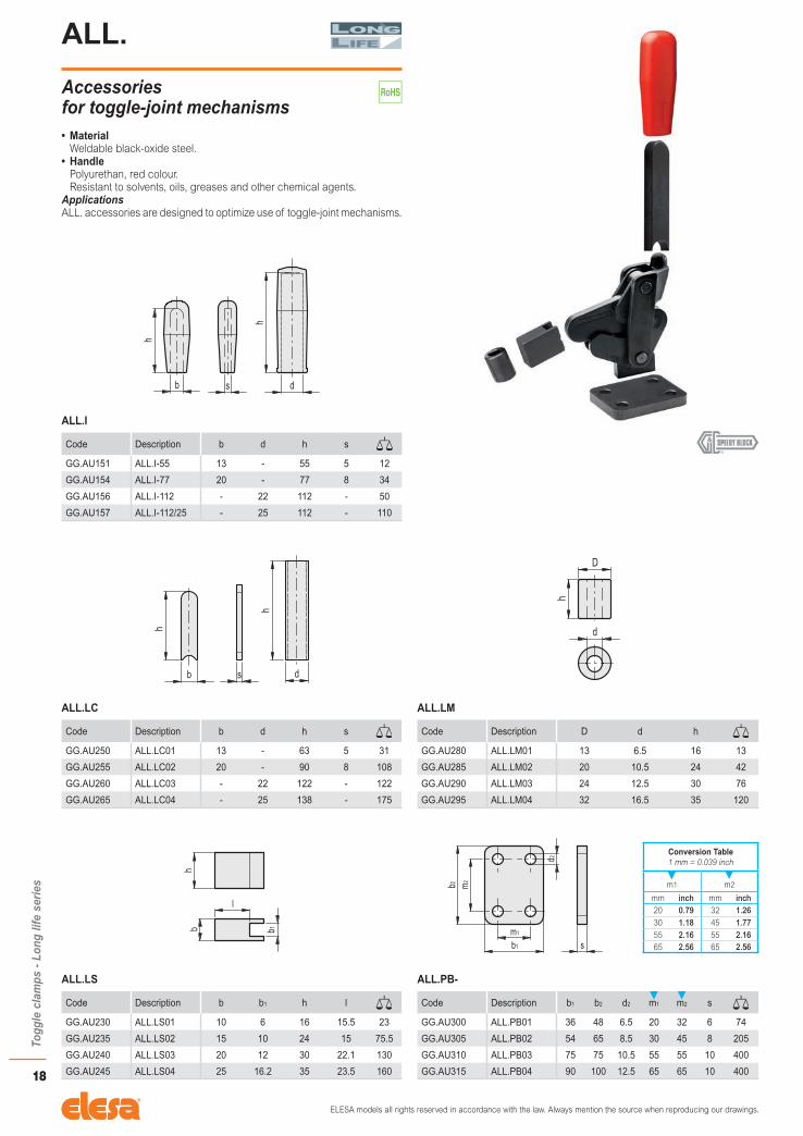
ALL.
Accessories for toggle-joint mechanisms• Material
Weldable black-oxide steel.• Handle
Polyurethan, red colour.Resistant to solvents, oils, greases and other chemical agents.
ApplicationsALL. accessories are designed to optimize use of toggle-joint mechanisms.
ALL.I
Code Description b d h s
GG.AU151 ALL.I-55 13 - 55 5 12
GG.AU154 ALL.I-77 20 - 77 8 34
GG.AU156 ALL.I-112 - 22 112 - 50
GG.AU157 ALL.I-112/25 - 25 112 - 110
ALL.LC
Code Description b d h s
GG.AU250 ALL.LC01 13 - 63 5 31
GG.AU255 ALL.LC02 20 - 90 8 108
GG.AU260 ALL.LC03 - 22 122 - 122
GG.AU265 ALL.LC04 - 25 138 - 175
ALL.LM
Code Description D d h
GG.AU280 ALL.LM01 13 6.5 16 13
GG.AU285 ALL.LM02 20 10.5 24 42
GG.AU290 ALL.LM03 24 12.5 30 76
GG.AU295 ALL.LM04 32 16.5 35 120
ALL.LS
Code Description b b1 h l
GG.AU230 ALL.LS01 10 6 16 15.5 23
GG.AU235 ALL.LS02 15 10 24 15 75.5
GG.AU240 ALL.LS03 20 12 30 22.1 130
GG.AU245 ALL.LS04 25 16.2 35 23.5 160
ALL.PB-
Code Description b1 b2 d2 m1 m2 s
GG.AU300 ALL.PB01 36 48 6.5 20 32 6 74
GG.AU305 ALL.PB02 54 65 8.5 30 45 8 205
GG.AU310 ALL.PB03 75 75 10.5 55 55 10 400
GG.AU315 ALL.PB04 90 100 12.5 65 65 10 400
Conversion Table1 mm = 0.039 inch
m1 m2
mm inch mm inch20 0.79 32 1.2630 1.18 45 1.7755 2.16 55 2.1665 2.56 65 2.56

ELESA models all rights reserved in accordance with the law. Always mention the source when reproducing our drawings.
19
Togg
le c
lam
ps -
Hor
izon
tal s
erie
s
MOC.
Horizontal toggle clamps with folded base• Material
C10 zinc-plated steel (MOC-MF).AISI 304 stainless steel (MOC-MFX).
• RivetsZinc-plated steel (MOC-MF).AISI 304 stainless steel (MOC-MFX).
• Support bushingHardened and ground steel (for sizes ≥355).
• HandlePolyurethan, red colour.Resistant to solvents, oils, greases and other chemical agents.
• Standard executions - MOC-MF: with open clamping lever and two folded washers. - MOC-MFX: with open clamping lever and two folded washers.
• Clamping boltsTo be ordered separately.
Features and applicationsAll articulated joints are lubricated with special grease.All articulated joints are lubricated with special grease. MOC. toggle clamps have been designed for front mounting and to avoid that the operator's fingers may be hit by the lever while opening.During clamping, the lever is controlled to prevent impact on functioning due to side thrust.
MOC-MF
Code Description a b1 b2 b3 d1 d2 h1 h2 h3 h4 l l1 m1 m2 r sFH1 [N]*
FH2 [N]*
GG.AD076 MOC.75-MF 20 30 25.5 5.5 M5 4.5 62 45 11 22.5 36 118 18 13.5 42.5 2 900 1350 105
GG.AD136 MOC.130-MF 32 39 35 6.5 M6 5.5 85 65 14 27 53 170 26 22 61 2.5 1000 2000 240
GG.AD271 MOC.230-MF 37 43 40 8.5 M8 6.5 102 77 18 35 61 195 28.5 24 70 3 1700 3300 400
GG.AD371 MOC.355-MF 58 52 52 10.5 M10 8.5 135 102 22 43 96 270 32 32 108.5 3.5 1800 4000 840
MOC-MFX
Code Description a b1 b2 b3 d1 d2 h1 h2 h3 h4 l l1 m1 m2 r sFH1 [N]*
FH2 [N]*
GG.DS076 MOC.75-MFX 20 30 25.5 5.5 M5 4.5 62 45 11 22.5 36 118 18 13.5 42.5 2 900 1350 105
GG.DS136 MOC.130-MFX 32 39 35 6.5 M6 5.5 85 65 14 27 53 170 26 22 61 2.5 1000 2000 240
GG.DS271 MOC.230-MFX 37 43 40 8.5 M8 6.5 102 77 18 35 61 195 28.5 24 70 3 1700 3300 400
* Holding force.
Conversion Table1 mm = 0.039 inch
m1 m2
mm inch mm inch18 0.71 13.5 0.5326 1.02 22 0.87
28.5 1.12 24 0.9432 1.26 32 1.26
ELESA models all rights reserved in accordance with the law. Always mention the source when reproducing our drawings.
20
Togg
le c
lam
ps -
Hor
izon
tal s
erie
sMOA.
Horizontal toggle clamps with folded base• Material
C10 zinc-plated steel.• Rivets
Zinc-plated steel.• Support bushing
Hardened and ground steel (for sizes ≥355).• Handle
Polyurethan, red colour.Resistant to solvents, oils, greases and other chemical agents.
• Standard executions - MOA-M: with open clamping lever and two folded washers. - MOA-O: with solid clamping lever and bolt retainer.
• Clamping boltsTo be ordered separately (code GG.AD025 included in the supply).
Features and applicationsAll articulated joints are lubricated with special grease.Main feature of MOA. toggle clamps is the low clamping profile. These tools are designed to avoid that the operator's fingers may be hit by the lever while opening. During clamping, the lever is controlled to prevent impact on functioning due to side thrust.During clamping, the lever is controlled to prevent impact on functioning due to side thrust.
MOA-M
Code Description a b1 b2 b3 d1 d2 h1 h2 h3 h4 l l1 l2 m1 m2 s1FH1 [N]*
FH2 [N]*
GG.AD025 MOA.25-M 10 24 24.5 4.2 M4 4.3 23 12 7 15 19 68 20 15 16 1.2 400 - 25
GG.AD075 MOA.75-M 20 28 26 5.5 M5 4.5 37 20 11 22.5 40 118 40 13.5 17 2 900 1350 88
GG.AD135 MOA.130-M 32 36 40 6.5 M6 5.5 51 29 14 27 56 170 53 26 26 2.5 1000 2000 200
GG.AD270 MOA.230-M 37 44 42 8.5 M8 6.5 61.5 36.5 18 35 65 195 63.5 26 28.5 3 1700 3300 330
GG.AD370 MOA.355-M 58 60 56 10 M10 8.5 83 50 22 43 100 269 96 41 41 3.5 1800 4000 700
GG.AD470 MOA.455-M 65 70 65 12.4 M12 8.5 98.5 60 26 53 115 308 116 41.5 41.5 4 3200 6200 1200
MOA-O
Code Description b1 b2 d1 d2 h1 h2 h3 l l1 l3 m1 m2 s s1FH1 [N]*
FH2 [N]*
GG.AD085 MOA.75-O 28 26 M5 4.5 37 20 11 40.5 118.5 49.5 13.5 17 4 2 900 1350 88
GG.AD145 MOA.130-O 36 40 M6 5.5 51 29 14 57 171 64 26 26 5 2.5 1000 2000 200
GG.AD280 MOA.230-O 44 42 M8 6.5 61.5 36.5 18 67 197 78 26 28.5 6 3 1700 3300 340
GG.AD380 MOA.355-O 60 56 M10 8.5 83 50 22 102 271 115 41 41 7 3.5 1800 4000 720
GG.AD480 MOA.455-O 70 65 M12 8.5 98.5 60 26 117 310 135 41.5 41.5 10 4 3200 6200 1230
* Holding force.
Conversion Table1 mm = 0.039 inch
m1 m2
mm inch mm inch15 0.59 16 0.63
13.5 0.53 17 0.6726 1.02 26 1.0241 1.61 28.5 1.12
41.5 1.63 41 1.6141.5 1.63

ELESA models all rights reserved in accordance with the law. Always mention the source when reproducing our drawings.
21
Togg
le c
lam
ps -
Hor
izon
tal s
erie
s
MOA-SST
Horizontal toggle clamps with folded base• Material
AISI 304 stainless steel.• Rivets
AISI 304 stainless steel.• Handle
Polyurethan, red colour.Resistant to solvents, oils, greases and other chemical agents.
• Standard executions - MOA-MX: with open clamping lever and two folded washers. - MOA-OX: with solid clamping lever and bolt retainer.
• Clamping boltsTo be ordered separately (code GG.DS025 included in the supply).
Features and applicationsAll articulated joints are lubricated with special grease.Main feature of MOA. toggle clamps is the low clamping profile. These tools are designed to avoid that the operator's fingers may be hit by the lever while opening. During clamping, the lever is controlled to prevent impact on functioning due to side thrust.During clamping, the lever is controlled to prevent impact on functioning due to side thrust.
MOA-MX
Code Description a b1 b2 b3 d1 d2 h1 h2 h3 h4 l l1 l2 m1 m2 s1FH1 [N]*
FH2 [N]*
GG.DS025 MOA.25-MX 10 24 24.5 4.2 M4 4.3 23 12 7 15 19 68 20 15 16 1.2 400 - 25
GG.DS075 MOA.75-MX 20 28 26 5.5 M5 4.5 37 20 11 22.5 40 118 40 13.5 17 2 900 1350 88
GG.DS135 MOA.130-MX 32 36 40 6.5 M6 5.5 51 29 14 27 56 170 53 26 26 2.5 1000 2000 200
GG.DS270 MOA.230-MX 37 44 42 8.5 M8 6.5 61.5 36.5 18 35 65 195 63.5 26 28.5 3 1700 3300 330
MOA-OX
Code Description b1 b2 d1 d2 h1 h2 h3 l l1 l3 m1 m2 s s1FH1 [N]*
FH2 [N]*
GG.DS085 MOA.75-OX 28 26 M5 4.5 37 20 11 40.5 118.5 49.5 13.5 17 4 2 900 1350 88
GG.DS145 MOA.130-OX 36 40 M6 5.5 51 29 14 57 171 64 26 26 5 2.5 1000 2000 200
GG.DS280 MOA.230-OX 44 42 M8 6.5 61.5 36.5 18 67 197 78 26 28.5 6 3 1700 3300 340
* Holding force.
Conversion Table1 mm = 0.039 inch
m1 m2
mm inch mm inch15 0.59 16 0.63
13.5 0.53 17 0.6726 1.02 26 1.02
28.5 1.12
ELESA models all rights reserved in accordance with the law. Always mention the source when reproducing our drawings.
22
Togg
le c
lam
ps -
Hor
izon
tal s
erie
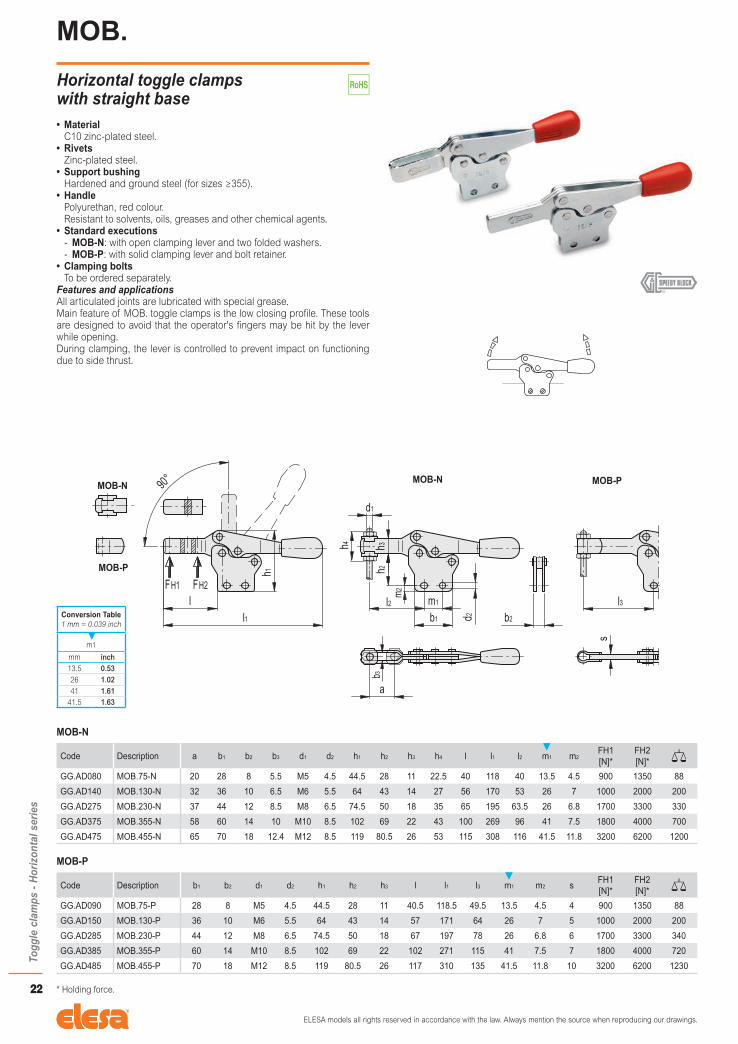
sMOB.
Horizontal toggle clamps with straight base• Material
C10 zinc-plated steel.• Rivets
Zinc-plated steel.• Support bushing
Hardened and ground steel (for sizes ≥355).• Handle
Polyurethan, red colour.Resistant to solvents, oils, greases and other chemical agents.
• Standard executions - MOB-N: with open clamping lever and two folded washers. - MOB-P: with solid clamping lever and bolt retainer.
• Clamping boltsTo be ordered separately.
Features and applicationsAll articulated joints are lubricated with special grease.Main feature of MOB. toggle clamps is the low closing profile. These tools are designed to avoid that the operator's fingers may be hit by the lever while opening.During clamping, the lever is controlled to prevent impact on functioning due to side thrust.
MOB-N
Code Description a b1 b2 b3 d1 d2 h1 h2 h3 h4 l l1 l2 m1 m2FH1 [N]*
FH2 [N]*
GG.AD080 MOB.75-N 20 28 8 5.5 M5 4.5 44.5 28 11 22.5 40 118 40 13.5 4.5 900 1350 88
GG.AD140 MOB.130-N 32 36 10 6.5 M6 5.5 64 43 14 27 56 170 53 26 7 1000 2000 200
GG.AD275 MOB.230-N 37 44 12 8.5 M8 6.5 74.5 50 18 35 65 195 63.5 26 6.8 1700 3300 330
GG.AD375 MOB.355-N 58 60 14 10 M10 8.5 102 69 22 43 100 269 96 41 7.5 1800 4000 700
GG.AD475 MOB.455-N 65 70 18 12.4 M12 8.5 119 80.5 26 53 115 308 116 41.5 11.8 3200 6200 1200
MOB-P
Code Description b1 b2 d1 d2 h1 h2 h3 l l1 l3 m1 m2 sFH1 [N]*
FH2 [N]*
GG.AD090 MOB.75-P 28 8 M5 4.5 44.5 28 11 40.5 118.5 49.5 13.5 4.5 4 900 1350 88
GG.AD150 MOB.130-P 36 10 M6 5.5 64 43 14 57 171 64 26 7 5 1000 2000 200
GG.AD285 MOB.230-P 44 12 M8 6.5 74.5 50 18 67 197 78 26 6.8 6 1700 3300 340
GG.AD385 MOB.355-P 60 14 M10 8.5 102 69 22 102 271 115 41 7.5 7 1800 4000 720
GG.AD485 MOB.455-P 70 18 M12 8.5 119 80.5 26 117 310 135 41.5 11.8 10 3200 6200 1230
* Holding force.
Conversion Table1 mm = 0.039 inch
m1
mm inch13.5 0.5326 1.0241 1.61
41.5 1.63

ELESA models all rights reserved in accordance with the law. Always mention the source when reproducing our drawings.
23
Togg
le c
lam
ps -
Hor
izon
tal s
erie
s
MOB-SST
Horizontal toggle clamps with straight base• Material
AISI 304 stainless steel.• Rivets
AISI 304 stainless steel.• Handle
Polyurethan, red colour.Resistant to solvents, oils, greases and other chemical agents.
• Standard executions - MOB-NX: with open clamping lever and two folded washers. - MOB-PX: with solid clamping lever and bolt retainer.
• Clamping boltsTo be ordered separately.
Features and applicationsAll articulated joints are lubricated with special grease.Main feature of MOB. toggle clamps is the low closing profile. These tools are designed to avoid that the operator's fingers may be hit by the lever while opening.During clamping, the lever is controlled to prevent impact on functioning due to side thrust.
MOB-NX
Code Description a b1 b2 b3 d1 d2 h1 h2 h3 h4 l l1 l2 m1 m2FH1 [N]*
FH2 [N]*
GG.DS080 MOB.75-NX 20 28 8 5.5 M5 4.5 44.5 28 11 22.5 40 118 40 13.5 4.5 900 1350 88
GG.DS140 MOB.130-NX 32 36 10 6.5 M6 5.5 64 43 14 27 56 170 53 26 7 1000 2000 200
GG.DS275 MOB.230-NX 37 44 12 8.5 M8 6.5 74.5 50 18 35 65 195 63.5 26 6.8 1700 3300 330
MOB-PX
Code Description b1 b2 d1 d2 h1 h2 h3 l l1 l3 m1 m2 sFH1 [N]*
FH2 [N]*
GG.DS090 MOB.75-PX 28 8 M5 4.5 44.5 28 11 40.5 118.5 49.5 13.5 4.5 4 900 1350 88
GG.DS150 MOB.130-PX 36 10 M6 5.5 64 43 14 57 171 64 26 7 5 1000 2000 200
GG.DS285 MOB.230-PX 44 12 M8 6.5 74.5 50 18 67 197 78 26 6.8 6 1700 3300 340
* Holding force.
Conversion Table1 mm = 0.039 inch
m1
mm inch13.5 0.5326 1.02
ELESA models all rights reserved in accordance with the law. Always mention the source when reproducing our drawings.
24
Togg
le c
lam
ps -
Pus
h-pu
ll cl
amps
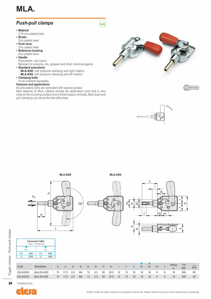
MLA.
Push-pull clamps• Material
C10 zinc-plated steel.• Rivets
Zinc-plated steel.• Push lever
Zinc-plated steel.• Reference bushing
Zinc-plated steel.• Handle
Polyurethan, red colour.Resistant to solvents, oils, greases and other chemical agents.
• Standard executions - MLA-ASD: with pressure clamping and right rotation. - MLA-ASS: with pressure clamping and left rotation.
• Clamping boltsTo be ordered separately.
Features and applicationsAll articulated joints are lubricated with special grease.Main features of MLA. clamps include the application point that is very close to the mounting surface and a limited space vertically. Both push and pull clamping can be performed effectively.
Code Description a b d1 d2 d3 d4 h1 h2 l l1 l2 m1 m2 m3 tStroke
wFH [N]*
GG.AG050 MLA.50-ASD 10 17.5 6.5 M4 12 4.3 90 30.5 12 73 33 16 16 8 9 16 800 60
GG.AG055 MLA.50-ASS 10 17.5 6.5 M4 12 4.3 90 30.5 12 73 33 16 16 8 9 16 800 60
* Holding force.
Conversion Table1 mm = 0.039 inch
m1 m2
mm inch mm inch16 0.63 16 0.63

ELESA models all rights reserved in accordance with the law. Always mention the source when reproducing our drawings.
25
Togg
le c
lam
ps -
Pus
h-pu
ll cl
amps
MLB.
Push-pull clamps• Material
C10 zinc-plated steel.• Rivets
Zinc-plated steel.• Base
- MLB.70: black painted brass, pass-through holes for cylindrical head screws.
- MLB.160: black painted steel, pass-through holes.• Push lever
Zinc-plated steel.• Handle
Polyurethan, red colour.Resistant to solvents, oils, greases and other chemical agents.
• Standard executions - MLB-ASD: with pressure clamping and right rotation. - MLB-ASS: with pressure clamping and left rotation.
• Clamping boltsTo be ordered separately.
Features and applicationsAll articulated joints are lubricated with special grease.Main features of MLB. clamps include the application point that is very close to the mounting surface and a limited space vertically. Both push and pull clamping can be performed effectively.
Code Description a b d1 d2 d3 h1 h2 l1 l2 m1 m2 m3 s tStroke
wFH [N]*
GG.AG075 MLB.70-ASD 12 19.5 8.5 M6 4.3 98 36 85 22 26 26 13 6 12 20 900 170
GG.AG165 MLB.160-ASD 15 25 11 M6 5.3 150 46 117 32 36.5 33.5 11 10 12 30 1300 400
GG.AG080 MLB.70-ASS 12 19.5 8.5 M6 4.3 98 36 85 22 26 26 13 6 12 20 900 170
GG.AG170 MLB.160-ASS 15 25 11 M6 5.3 150 46 117 32 36.5 33.5 11 10 12 30 1300 400
* Holding force.
Conversion Table1 mm = 0.039 inch
m1 m2
mm inch mm inch26 1.02 26 1.02
36.5 1.44 33.5 1.32

ELESA models all rights reserved in accordance with the law. Always mention the source when reproducing our drawings.
26
Togg
le c
lam
ps -
Pus
h-pu
ll cl
amps
MFA.
Push-pull clamps• Material
C10 zinc-plated steel.• Rivets
Zinc-plated steel.• Push lever
Zinc-plated steel.• Reference bushing
Zinc-plated brass.• Nut
Zinc-plated steel.• Handle
Polyurethan, red colour.Resistant to solvents, oils, greases and other chemical agents.
• Clamping boltsTo be ordered separately.
Features and applicationsAll articulated joints are lubricated with special grease.MFA. clamps ensure only perfect push clamping.
Code Description a b d1 d2 d3 h1 h2 l1 l2 l3 l4 m1 m2 m3 s tStroke
wFH [N]*
GG.AG120 MFA.120-AS 17 48 12 M6 5.5 111 32 130 40 10 3 34 30 18 24 12 20 3600 350
GG.AG300 MFA.300-AS 20 58 14 M8 6.5 140 36 167 57 12 3 50 34 18 27 16 33 7200 560
* Holding force.
Conversion Table1 mm = 0.039 inch
m1 m2
mm inch mm inch34 1.34 30 1.1850 1.97 34 1.34

ELESA models all rights reserved in accordance with the law. Always mention the source when reproducing our drawings.
27
Togg
le c
lam
ps -
Pus
h-pu
ll cl
amps
MFC.
Push-pull clamps• Material
C10 zinc-plated steel.• Rivets
Zinc-plated steel.• Base
- Black coated brass, for size 70 and 160. - Black coated pressed steel, for size 360 to 3100.
• Push leverZinc-plated steel.
• HandlePolyurethan, red colour.Resistant to solvents, oils, greases and other chemical agents.
• Clamping boltsTo be ordered separately.
Features and applicationsAll articulated joints are lubricated with special grease.MFC. clamps are suitable for use requiring high resistant torque given their solid base body. Both push and pull clamping can be performed effectively.
Code Description a b1 b2 d1 d2 d3 h1 l1 l2 m1 m2 m3 m4 s tStroke
wFH [N]*
GG.AG070 MFC.70-AS 12 64 36 8.5 M6 4.3 42.5 86 22 26 13 - 26 6 12 20 1200 170
GG.AG160 MFC.160-AS 15 85 46 11 M6 5.5 56 116 31 33.5 11 - 36.5 10 12 30 2800 400
GG.AG351 MFC.360-AS 25 90 45.5 12 M8 5.5 72 122 32 33.5 30 - 36.5 7 15 32 5600 440
GG.AG355 MFC.550-AS 18 122.5 55 14 M8 7 76 164.5 42 41 15 35 41 6 16 42 8000 700
GG.AG361 MFC.1100-AS 25 133 57 16 M10 8.5 95 182 49 41 15 35 41 7 18 50 16000 1060
GG.AG371 MFC.2100-AS 35 177 70 20 M12 8.5 118.5 238 61 50 35 50 50 9.5 22 60 25000 2280
GG.AG381 MFC.3100-AS 40 216 76 22 M14 11 137 316 100 54 40 70 70 9.5 25 100 45000 3350
* Holding force.
Conversion Table1 mm = 0.039 inch
m1 m2 m3 m4
mm inch mm inch mm inch mm inch26 1.02 13 0.51 35 1.38 26 1.02
33.5 1.32 11 0.43 50 1.97 36.5 1.4341 1.61 30 1.18 70 2.75 41 1.6150 1.97 15 0.59 50 1.9754 2.12 35 1.38 70 2.75
40 1.57

ELESA models all rights reserved in accordance with the law. Always mention the source when reproducing our drawings.
28
Togg
le c
lam
ps -
Pus
h-pu
ll cl
amps
MFE.
Push-pull clamps• Material
C10 zinc-plated steel.• Rivets
Zinc-plated steel.• Push lever
Zinc-plated steel.• Reference bushing
Zinc-plated steel.• Nut
Zinc-plated steel.• Bushing fixing screws
Zinc-plated steel.• Handle
Polyurethan, red colour.Resistant to solvents, oils, greases and other chemical agents.
• Fixing squareZinc-plated steel (to be ordered separately).
• Clamping boltsTo be ordered separately.
Features and applicationsAll articulated joints are lubricated with special grease.Thanks to the front outer thread, MFE. clamps can be mounted in a way that the control lever is conveniently positioned using fixing squares (to be ordered separately), or frontally directly on the equipment. Both push and pull clamping can be performed effectively.
MFE.
Code Description b1 b2 d h m1 m2 m3 s1
GG.AG416 MFE.30080 35 22 5.5 24 20 8 - 4
GG.AG421 MFE.30165 60 41 6.5 32 41 13.5 19 5
GG.AG426 MFE.30340 75 59 8.5 48 55 19 25 5
MFE-AS
Code Description b d1 d2 d3 h1 h2 l1 l2 l3 l4 l5 s tStroke
wFH [N]*
GG.AG401 MFE.80-AS 24 10 M6 M16x1.5 120 19 71 38 15.5 10 8 24 12 21 3000 135
GG.AG406 MFE.165-AS 28 12 M8 M20x1.5 194 22 113 59 20 16 9 30 15 38 5400 335
GG.AG411 MFE.340-AS 38 16 M10 M24x2 256 30 173 90 22 28 10 36 18 66 7000 835
* Holding force.
Conversion Table1 mm = 0.039 inch
m1 m3
mm inch mm inch20 0.79 19 0.7541 1.61 25 0.9855 2.16

ELESA models all rights reserved in accordance with the law. Always mention the source when reproducing our drawings.
29
Togg
le c
lam
ps -
Pus
h-pu
ll cl
amps
MFE-SST
Push-pull clamps• Material
AISI 304 stainless steel.• Rivets
AISI 304 stainless steel.• Push lever
AISI 304 stainless steel.• Reference bushing
AISI 303 stainless steel.• Nut
AISI 304 stainless steel.• Bushing fixing screws
AISI 303 stainless steel.• Handle
Polyurethan, red colour.Resistant to solvents, oils, greases and other chemical agents.
• Fixing squareAISI 304 stainless steel (to be ordered separately).
• Clamping boltsTo be ordered separately.
Features and applicationsAll articulated joints are lubricated with special grease.Thanks to the front outer thread, MFE. clamps can be mounted in a way that the control lever is conveniently positioned using fixing squares (to be ordered separately), or frontally directly on the equipment. Both push and pull clamping can be performed effectively.
MFE-X
Code Description b1 b2 d h m1 m2 m3 s1
GG.AS416 MFE.30080X 35 22 5.5 24 20 8 - 4
GG.AS421 MFE.30165X 60 41 6.5 32 41 13.5 19 5
GG.AS426 MFE.30340X 75 59 8.5 48 55 19 25 5
MFE-ASX
Code Description b d1 d2 d3 h1 h2 l1 l2 l3 l4 l5 s tStroke
wFH [N]*
GG.AS401 MFE.80-ASX 24 10 M6 M16x1.5 120 19 71 38 15.5 10 8 24 12 21 3000 135
GG.AS406 MFE.165-ASX 28 12 M8 M20x1.5 194 22 113 59 20 16 9 30 15 38 5400 335
GG.AS411 MFE.340-ASX 38 16 M10 M24x2 256 30 173 90 22 28 10 36 18 66 7000 835
* Holding force.
Conversion Table1 mm = 0.039 inch
m1 m3
mm inch mm inch20 0.79 19 0.7541 1.61 25 0.9855 2.16

ELESA models all rights reserved in accordance with the law. Always mention the source when reproducing our drawings.
30
Togg
le c
lam
ps -
Latc
h cl
amps
MTB.
Latch clamps with safety stop• Material
C10 zinc-plated steel.• Rivets
Zinc-plated steel.• Handle
Polyurethan, red colour.Resistant to solvents, oils, greases and other chemical agents.
• Standard executions - MTB.T5: without tie rod. - MTB.T5-TG: with eyelet tie rod. - MTB.T5-TT: with T tie rod - MTB.T5-TU: with hook tie rod.
Features and applicationsAll articulated joints are lubricated with special grease.MTB. latch clamps are particularly suitable for equipment and applications with strong vibration stresses where it is required to assure the holding of the clamp engagement against accidental opening.By disengaging the safety device, pushing the slider (fig. 1) and using the handle, the clamp opens (fig. 2). By disengaging the safety device (fig. 3) and moving the control lever in the opposite direction (fig. 4), the result is the complete disengagement of the body of the clamp and the clamping plate.To re-engage the clamp, it is necessary to proceed in the opposite way.All these engaging and disengaging operations can be done by using one hand only, since in its movement the eyelet follows the lever.The engaging position can be length-regulated in order to suit better the application by means of a threaded eyelet, locked in place by a locking nut.
MTB.T5
Code Description a b1 b2 d h1 l1 m1 m2 sFH [N]*
GG.AL575 MTB.160-T5 13 26 28 4.5 26.8 103 16 19 2 1750 100
GG.AL580 MTB.320-T5 19 40 44 6.7 38.5 153 19 32 3 4000 295
GG.AL585 MTB.700-T5 28 60 54 8.5 53 222 41.5 38.1 3.5 7500 690
* Holding force.
Conversion Table1 mm = 0.039 inch
m1 m2
mm inch mm inch16 0.63 19 0.7519 0.75 32 1.26
41.5 1.63 38.1 1.50

ELESA models all rights reserved in accordance with the law. Always mention the source when reproducing our drawings.
31
Togg
le c
lam
ps -
Latc
h cl
amps
MTB.T5-TG
Code Description a b1 b2 d d1 h1 l m1 m2 r
GG.AL576 MTB.160-T5-TG 13 26 23 4.5 M6 19.8 28 16 14.3 55.5 100
GG.AL581 MTB.320-T5-TG 19 35 34 6.7 M8 30 34 19 22.3 76.5 295
GG.AL586 MTB.700-T5-TG 28 50 41 8.5 M10 40.5 42 31 25.4 95.5 690
MTB.T5-TT
Code Description a b1 b2 d d1 h1 l m1 r
GG.AL578 MTB.160-T5-TT 13 26 14 4.5 M6 20 28 16 55
GG.AL583 MTB.320-T5-TT 19 35 18 6.7 M8 30 34 19 76.5
GG.AL588 MTB.700-T5-TT 28 50 26 8.5 M10 40.5 42 31 93
MTB.T5-TU
Code Description a b1 b2 d d1 h1 l m1 r
GG.AL577 MTB.160-T5-TU 13 35 14 4.5 M6 20.4 28 25.4 54.5
GG.AL582 MTB.320-T5-TU 19 38 18 6.7 M8 28 34 25.4 76.25
GG.AL587 MTB.700-T5-TU 28 50 26 8.5 M10 39 42 31 92.75
Conversion Table1 mm = 0.039 inch
m1 m2
mm inch mm inch16 0.63 14.3 0.5619 0.75 22.3 0.8831 1.22 25.4 1.0
25.4 1.0

ELESA models all rights reserved in accordance with the law. Always mention the source when reproducing our drawings.
32
Togg
le c
lam
ps -
Latc
h cl
amps
MTB-SST
Latch clamps with safety stop• Material
AISI 304 stainless steel.• Rivets
AISI 304 stainless steel.• Handle
Polyurethan, red colour.Resistant to solvents, oils, greases and other chemical agents.
• Standard executions - MTB.T5X: without tie rod. - MTB.T5X-TG: with eyelet tie rod. - MTB.T5X-TT: with T tie rod. - MTB.T5X-TU: with hook tie rod.
Features and applicationsAll articulated joints are lubricated with special grease.MTB-SST latch clamps and are particularly suitable for equipment and applications with strong vibration stresses where it is required to assure the holding of the clamp engagement against accidental opening.By disengaging the safety device, pushing the slider (fig. 1) and using the handle, the clamp opens (fig. 2). By disengaging the safety device (fig. 3) and moving the control lever in the opposite direction (fig. 4), the result is the complete disengagement of the body of the clamp and the clamping plate.To re-engage the clamp, it is necessary to proceed in the opposite way.All these engaging and disengaging operations can be done by using one hand only, since in its movement the eyelet follows the lever.The engaging position can be length-regulated in order to suit better the application by means of a threaded eyelet, locked in place by a locking nut.
MTB.T5X
Code Description a b1 b2 d h1 l1 m1 m2 sFH [N]*
GG.AS545 MTB.160-T5X 13 26 28 4.5 26.8 103 16 19 2 1750 100
GG.AS550 MTB.320-T5X 19 40 44 6.7 38.5 153 19 32 3 4000 295
GG.AS555 MTB.700-T5X 28 60 54 8.5 53 222 41.5 38.1 3.5 7500 690
# Holding force.
Conversion Table1 mm = 0.039 inch
m1 m2
mm inch mm inch16 0.63 19 0.7519 0.75 32 1.26
41.5 1.63 38.1 1.50

ELESA models all rights reserved in accordance with the law. Always mention the source when reproducing our drawings.
33
Togg
le c
lam
ps -
Latc
h cl
amps
MTB.T5X-TG
Code Description a b1 b2 d d1 h1 l m1 m2 r
GG.AS546 MTB.160-T5X-TG 13 26 23 4.5 M6 19.8 28 16 14.3 55.5
GG.AS551 MTB.320-T5X-TG 19 35 34 6.7 M8 30 34 19 22.3 76.5
GG.AS556 MTB.700-T5X-TG 28 50 41 8.5 M10 40.5 42 31 25.4 95.5
MTB.T5X-TT
Code Description a b1 b2 d d1 h1 l m1 r
GG.AS548 MTB.160-T5X-TT 13 26 14 4.5 M6 20 28 16 55
GG.AS553 MTB.320-T5X-TT 19 35 18 6.7 M8 30 34 19 76.5
GG.AS558 MTB.700-T5X-TT 28 50 26 8.5 M10 40.5 42 31 93
MTB.T5X-TU
Code Description a b1 b2 d d1 h1 l m1 r
GG.AS547 MTB.160-T5X-TU 13 35 14 4.5 M6 20.4 28 25.4 54.5
GG.AS552 MTB.320-T5X-TU 19 38 18 6.7 M8 28 34 25.4 76.25
GG.AS557 MTB.700-T5X-TU 28 50 26 8.5 M10 39 42 31 92.75
Conversion Table1 mm = 0.039 inch
m1 m2
mm inch mm inch16 0.63 14.3 0.5619 0.75 22.3 0.8831 1.22 25.4 1.0
25.4 1.0

ELESA models all rights reserved in accordance with the law. Always mention the source when reproducing our drawings.
34
Togg
le c
lam
ps -
Latc
h cl
amps
MTC.
Latch clamps• Material
C10 zinc-plated steel.• Rivets
Zinc-plated steel.• Pulling hook
Parallel to clamping arm, zinc-plated steel.• Oscillating pin and nuts
Zinc-plated steel.• Handle
Polyurethan, red colour.Resistant to solvents, oils, greases and other chemical agents.
Features and applicationsAll articulated joints are lubricated with special grease.MTC. clamps ensure tight closing of any cover.The position of the pulling hook can be adjusted in length according to the specific applications.
Code Description a b1 b2 b3 b4 d1 d2 h1 h2 l1 m1 m2 m3 r sStroke
wFH [N]*
GG.AL500 MTC.160-T2 12 26 28 20 14 M4 4.3 25 18 98 19 16 10 35-44 2 25 1600 85
GG.AL505 MTC.320-T2 16 40 44 28 22 M6 6.5 30 25 152 32 19 14.3 54-63 3 48 3200 250
GG.AL510 MTC.700-T2 24 60 54 38 26 M8 8.5 42 36 220 38 41.5 19 70-90 3.5 58 7000 600
* Holding force.
Conversion Table1 mm = 0.039 inch
m1 m2 m3
mm inch mm inch mm inch19 0.75 16 0.63 10 0.3932 1.26 19 0.75 14.3 0.5638 1.50 41.5 1.63 19 0.75

ELESA models all rights reserved in accordance with the law. Always mention the source when reproducing our drawings.
35
Togg
le c
lam
ps -
Latc
h cl
amps
MTC-SST
Latch clamps• Material
AISI 304 stainless steel.• Rivets
AISI 304 stainless steel.• Pulling hook
Parallel to clamping arm, AISI 303 stainless steel.• Oscillating pin and nuts
AISI 303 stainless steel.• Handle
Polyurethan, red colour.Resistant to solvents, oils, greases and other chemical agents.
Features and applicationsAll articulated joints are lubricated with special grease.MTC. clamps ensure tight closing of any cover.The position of the pulling hook can be adjusted according to specific applications.
Code Description a b1 b2 b3 b4 d1 d2 h1 h2 l1 m1 m2 m3 r sStroke
wFH [N]*
GG.AS500 MTC.160-T2X 12 26 28 20 14 M4 4.3 25 18 98 19 16 10 35-44 2 25 1600 85
GG.AS505 MTC.320-T2X 16 40 44 28 22 M6 6.5 30 25 152 32 19 14.3 54-63 3 48 3200 250
GG.AS510 MTC.700-T2X 24 60 54 38 26 M8 8.5 42 36 220 38 41.5 19 70-90 3.5 58 7000 600
* Holding force.
Conversion Table1 mm = 0.039 inch
m1 m2 m3
mm inch mm inch mm inch19 0.75 16 0.63 10 0.3932 1.26 19 0.75 14.3 0.5638 1.50 41.5 1.63 19 0.75

ELESA models all rights reserved in accordance with the law. Always mention the source when reproducing our drawings.
36
Togg
le c
lam
ps -
Latc
h cl
amps
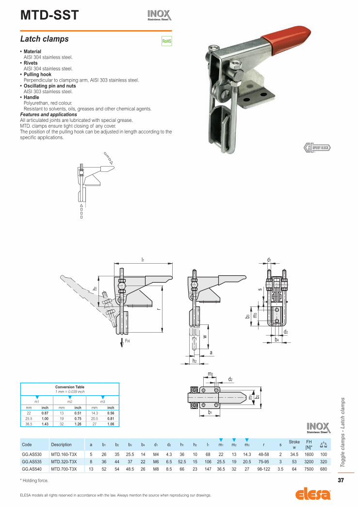
MTD.
Latch clamps• Material
C10 zinc-plated steel.• Rivets
Zinc-plated steel.• Pulling hook
Perpendicular to clamping arm, zinc-plated steel.• Oscillating pin and nuts
Zinc-plated steel.• Handle
Polyurethan, red colour.Resistant to solvents, oils, greases and other chemical agents.
Features and applicationsAll articulated joints are lubricated with special grease.MTD. clamps ensure tight closing of any cover.The position of the pulling hook can be adjusted in length according to the specific applications.
Code Description a b1 b2 b3 b4 d1 d2 h1 h2 l1 m1 m2 m3 r sStroke
wFH [N]*
GG.AL530 MTD.160-T3 5 26 35 25.5 14 M4 4.3 36 10 68 22 13 14.3 48-58 2 34.5 1600 100
GG.AL535 MTD.320-T3 8 36 44 37 22 M6 6.5 52.5 15 106 25.5 19 20.5 75-95 3 53 3200 320
GG.AL540 MTD.700-T3 13 52 54 48.5 26 M8 8.5 66 23 147 36.5 32 27 98-122 3.5 64 7500 680
* Holding force.
Conversion Table1 mm = 0.039 inch
m1 m2 m3
mm inch mm inch mm inch22 0.87 13 0.51 14.3 0.56
25.5 1.00 19 0.75 20.5 0.8136.5 1.43 32 1.26 27 1.06
ELESA models all rights reserved in accordance with the law. Always mention the source when reproducing our drawings.
37
Togg
le c
lam
ps -
Latc
h cl
amps
MTD-SST
Latch clamps• Material
AISI 304 stainless steel.• Rivets
AISI 304 stainless steel.• Pulling hook
Perpendicular to clamping arm, AISI 303 stainless steel.• Oscillating pin and nuts
AISI 303 stainless steel.• Handle
Polyurethan, red colour.Resistant to solvents, oils, greases and other chemical agents.
Features and applicationsAll articulated joints are lubricated with special grease.MTD. clamps ensure tight closing of any cover.The position of the pulling hook can be adjusted in length according to the specific applications.
Code Description a b1 b2 b3 b4 d1 d2 h1 h2 l1 m1 m2 m3 r sStroke
wFH [N]*
GG.AS530 MTD.160-T3X 5 26 35 25.5 14 M4 4.3 36 10 68 22 13 14.3 48-58 2 34.5 1600 100
GG.AS535 MTD.320-T3X 8 36 44 37 22 M6 6.5 52.5 15 106 25.5 19 20.5 75-95 3 53 3200 320
GG.AS540 MTD.700-T3X 13 52 54 48.5 26 M8 8.5 66 23 147 36.5 32 27 98-122 3.5 64 7500 680
* Holding force.
Conversion Table1 mm = 0.039 inch
m1 m2 m3
mm inch mm inch mm inch22 0.87 13 0.51 14.3 0.56
25.5 1.00 19 0.75 20.5 0.8136.5 1.43 32 1.26 27 1.06
ELESA models all rights reserved in accordance with the law. Always mention the source when reproducing our drawings.
38
Togg
le c
lam
ps -
Latc
h cl
amps
MTE.
Latch clamps• Material
C10 zinc-plated steel.• Rivets
Zinc-plated steel.• Pulling hook
Parallel to clamping arm, zinc-plated steel.• Oscillating pin and nuts
Zinc-plated steel.• Handle
Polyurethan, red colour.Resistant to solvents, oils, greases and other chemical agents.
Features and applicationsAll articulated joints are lubricated with special grease.MTE. clamps ensure tight closing of any cover.The position of the pulling hook can be adjusted in length according to the specific applications.
Code Description a b1 b2 b3 b4 d1 d2 h1 h2 l1 m1 m2 m3 r sStroke
wFH [N]*
GG.AL560 MTE.160-T4 5 26 35 25.5 14 M4 4.3 40 10 99 22 13 14.3 48-58 2 32 1600 95
GG.AL565 MTE.320-T4 8 36 44 37 22 M6 6.5 57.5 15 152 25.5 19 20.5 75-95 3 53 3200 295
GG.AL570 MTE.700-T4 13 52 54 48.5 26 M8 8.5 82 23 225 36.5 32 27 98-122 3.5 64 7500 655
* Holding force.
Conversion Table1 mm = 0.039 inch
m1 m2 m3
mm inch mm inch mm inch22 0.87 13 0.51 14.3 0.56
25.5 1.00 19 0.75 20.5 0.8136.5 1.43 32 1.26 27 1.06

ELESA models all rights reserved in accordance with the law. Always mention the source when reproducing our drawings.
39
Togg
le c
lam
ps -
Latc
h cl
amps
MTA.
Latch clamps• Material
C10 zinc-plated steel.• Rivets
Zinc-plated steel.• Pulling pin and hook
Zinc-plated steel.• Handle
Polyurethan, red colour.Resistant to solvents, oils, greases and other chemical agents.
• Standard executions - MTA-T: with pulling pin. - MTA-TF: with pulling hook.
Features and applicationsAll articulated joints are lubricated with special grease.MTA. clamps ensure tight closing of any cover.The position of the pulling hook (MTA-TF) can be adjusted according to specific applications.
MTA-T
Code Description a b1 b2 b3 d1 d3 h1 h2 l1 l2 m1 m2 sStroke
wFH [N]*
GG.AL200 MTA.200-T 37 35 45 18 10 6.5 49 16 203 51 32 19 3 100 2000 300
GG.AL300 MTA.300-T 35 48 60 21 10 8.3 49 18 226 51 45 32 3 104 3000 460
GG.AL400 MTA.400-T 43 54 84 26 14 10.5 60.5 25 278 58 60.5 28.5 5 160 4000 1000
MTA-TF
Code Description a b1 b2 d2 d3 h1 h2 l1 l3 m1 m2 r sStroke
wFH [N]*
GG.AL205 MTA.200-TF 29 35 45 8 6.5 49 16 250 93 32 19 5 3 100 2000 380
GG.AL305 MTA.300-TF 25 48 60 10 8.5 49 18 305 98 45 32 6 3 104 3000 560
GG.AL405 MTA.400-TF 30 54 84 11 10.5 60.5 25 343 117.5 60.5 28.5 7 5 160 4000 1200
* Holding force.
Conversion Table1 mm = 0.039 inch
m1 m2
mm inch mm inch32 1.26 19 0.7545 1.77 32 1.26
60.5 2.38 28.5 1.12

ELESA models all rights reserved in accordance with the law. Always mention the source when reproducing our drawings.
40
Togg
le c
lam
ps -
Latc
h cl
amps
MTP.
Latch clamps Heavy-duty series• Material
Black coated weldable steel.• Shank
Ground and hardened steel.• Pulling hook
Zinc-plated steel.• Oscillating pin and nuts
Zinc-plated steel.Features and applicationsAll articulated joints are lubricated with special grease.MTP. clamps ensure tight closing of any cover; they are suitable for use with high resistant torque thanks to high mechanical resistance of materials.The position of the pulling hook can be adjusted in length according to the specific applications.
Code Description a b1 b2 b3 d1 d2 d3 h1 h2 l1 m1 m2 m3 r sStroke
wFH [N]*
GG.AL600 MTP.1400-T2 21 68 64 48 M10 8.5 14 52 34 220 45 45 28 93-105 7 63 17000 1110
GG.AL610 MTP.2800-T2 27 85 80 60 M12 10.5 16 65 42 273 57 57 35 113-123 9 78 40000 2070
* Holding force.
Conversion Table1 mm = 0.039 inch
m1 m2 m3
mm inch mm inch mm inch45 1.77 45 1.77 28 1.1057 2.24 57 2.24 35 1.38

ELESA models all rights reserved in accordance with the law. Always mention the source when reproducing our drawings.
41
Togg
le c
lam
ps -
Latc
h cl
amps
MTP-SST
Latch clamps Heavy-duty series• Material
AISI 304 stainless steel.• Shank
AISI 303 stainless steel.• Pulling hook
AISI 303 stainless steel.• Oscillating pin and nuts
AISI 303 stainless steel.Features and applicationsAll articulated joints are lubricated with special grease.MTP. clamps ensure tight closing of any cover; they are suitable for use with high resistant torque thanks to high mechanical resistance of materials.The position of the pulling hook can be adjusted in length according to the specific applications.
Code Description a b1 b2 b3 d1 d2 d3 h1 h2 l1 m1 m2 m3 r sStroke
wFH [N]*
GG.AS580 MTP.1400-T2X 21 68 64 48 M10 8.5 14 52 34 220 45 45 28 93-105 7 63 14000 1110
GG.AS585 MTP.2800-T2X 27 85 80 60 M12 10.5 16 65 42 273 57 57 35 113-123 9 78 30000 2070
* Holding force.
Conversion Table1 mm = 0.039 inch
m1 m2 m3
mm inch mm inch mm inch45 1.77 45 1.77 28 1.1057 2.24 57 2.24 35 1.38

ELESA models all rights reserved in accordance with the law. Always mention the source when reproducing our drawings.
42
Togg
le c
lam
ps -
Latc
h cl
amps
MTS.
Weldable latch clamps Heavy-duty series• Material
Weldable black-oxide steel.• Shank
Ground and hardened steel.• Pulling hook
Zinc-plated steel.• Oscillating pin and nuts
Zinc-plated steel.Features and applicationsAll articulated joints are lubricated with special grease.MTS. clamps ensure tight closing of any cover; they are suitable for use with high resistant torque thanks to high mechanical resistance of materials.The position of the pulling hook can be adjusted in length according to the specific applications.
Code Description a b1 b2 b3 b4 d1 h1 h2 l1 m1 r sStroke
wFH [N]*
GG.AL620 MTS.1400-T2S 21 68 64 26.5 38 M10 52 34.5 216 46 93-105 9.2 63 17000 930
GG.AL630 MTS.2800-T2S 27 80 80 32 50 M12 65 43 257 55 102-123 12.7 78 40000 1708
* Holding force.

ELESA models all rights reserved in accordance with the law. Always mention the source when reproducing our drawings.
43
Togg
le c
lam
ps -
Latc
h cl
amps
MTS-SST
Weldable latch clamps Heavy-duty series• Material
AISI 304 stainless steel.• Shank
AISI 303 stainless steel.• Pulling hook
AISI 303 stainless steel.• Oscillating pin and nuts
AISI 303 stainless steel.Features and applicationsAll articulated joints are lubricated with special grease.MTS. clamps ensure tight closing of any cover; they are suitable for use with high resistant torque thanks to high mechanical resistance of materials.The position of the pulling hook can be adjusted in length according to the specific applications.
Code Description a b1 b2 b3 b4 d1 h1 h2 l1 m1 r sStroke
wFH [N]*
GG.AS590 MTS.1400-T2SX 21 68 64 26.5 38 M10 52 34.5 216 46 93-105 9.2 63 14000 930
GG.AS595 MTS.2800-T2SX 27 80 80 32 50 M12 65 43 257 55 102-123 12.7 78 30000 1708
* Holding force.

ELESA models all rights reserved in accordance with the law. Always mention the source when reproducing our drawings.
44
Togg
le c
lam
ps -
Latc
h cl
amps
MTL.
Latch clamps with safety device Heavy-duty series• Material
Weldable black-oxide steel.• Pins
Ground and hardened steel.• Handle
Polyurethan, red colour.Resistant to solvents, oils, greases and other chemical agents.
Features and applicationsAll articulated joints are lubricated with special grease.MTL. clamps ensure tight closing and are particularly suitable for applications where it is required to exert a high resistance force with a further assurance of the holding of the clamp engagement, very useful in case of strong vibration stresses.By disengaging the safety device, pushing the slider (fig. 1) and using the handle, the clamp opens (fig. 2). By disengaging the safety device (fig. 3) and moving the control lever in the opposite direction (fig. 4), the result is the complete disengagement of the body of the clamp and the clamping plate.To re-engage the clamp, it is necessary to proceed in the opposite way.All these engaging and disengaging operations can be done by using one hand only, since in its movement the eyelet follows the lever.The engaging position can be length-regulated in order to suit better the application by means of a threaded eyelet, locked in place by a grub screw.
Code Description a b1 b2 b3 d1 d2 h1 h2 l1 m1 m2 m3 r sStroke
wFH [N]*
GG.AL590 MTL.1400-T5 22 115 51 66 8.5 13 57 38 318 21 95 44 95-105 5 24 15000 1600
* Holding force.
Conversion Table1 mm = 0.039 inch
m1 m2 m3
mm inch mm inch mm inch21 0.83 95 3.74 44 1.73
ELESA models all rights reserved in accordance with the law. Always mention the source when reproducing our drawings.
45
Togg
le c
lam
ps -
Latc
h cl
amps
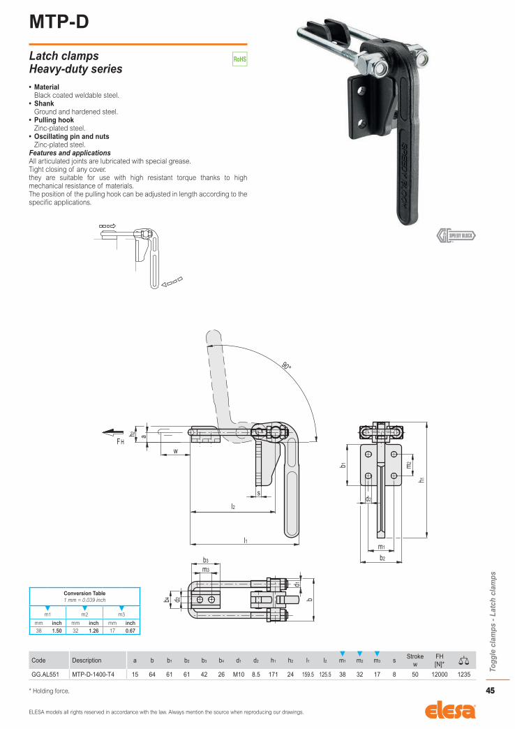
MTP-D
Latch clamps Heavy-duty series• Material
Black coated weldable steel.• Shank
Ground and hardened steel.• Pulling hook
Zinc-plated steel.• Oscillating pin and nuts
Zinc-plated steel.Features and applicationsAll articulated joints are lubricated with special grease.Tight closing of any cover.they are suitable for use with high resistant torque thanks to high mechanical resistance of materials.The position of the pulling hook can be adjusted in length according to the specific applications.
Code Description a b b1 b2 b3 b4 d1 d2 h1 h2 l1 l2 m1 m2 m3 sStroke
wFH [N]*
GG.AL551 MTP-D-1400-T4 15 64 61 61 42 26 M10 8.5 171 24 159.5 125.5 38 32 17 8 50 12000 1235
* Holding force.
Conversion Table1 mm = 0.039 inch
m1 m2 m3
mm inch mm inch mm inch38 1.50 32 1.26 17 0.67

ELESA models all rights reserved in accordance with the law. Always mention the source when reproducing our drawings.
46
Togg
le c
lam
ps -
Latc
h cl
amps
MTS-D
Weldable latch clamps Heavy-duty series• Material
Weldable black-oxide steel.• Shank
Ground and hardened steel.• Pulling hook
Zinc-plated steel.• Oscillating pin and nuts
Zinc-plated steel.Features and applicationsAll articulated joints are lubricated with special grease.Tight closing of any cover.they are suitable for use with high resistant torque thanks to high mechanical resistance of materials.The position of the pulling hook can be adjusted in length according to the specific applications.
Code Description a b b1 b2 b3 b4 d1 d2 h1 h2 l l2 m1 sStroke
wFH [N]*
GG.AL552 MTS-D-1400-T3S 15 64 61 26 42 26 M10 8.5 171 24 159.5 125.5 17 8 50 12000 1115
* Holding force.
Conversion Table1 mm = 0.039 inch
m1
mm inch17 0.67

ELESA models all rights reserved in accordance with the law. Always mention the source when reproducing our drawings.
47
Togg
le c
lam
ps -
Ser
ies
for
high
tem
pera
ture
s
MTR.
Weldable latch clamps• Material
Black coated weldable steel.• Shank
Ground and hardened steel.• Pulling hook
Natural steel.• Oscillating pin and nuts
Natural steel.• Standard executions
- MTR.1500: with clamping hole by removable tube. - MTR.1510: with clamping lever.
Features and applicationsAll articulated joints are lubricated with special grease.MTR. latch clamps are particularly suitable for applications on moulds of plastic products and rotational.The small dimensions of MTR.1500 execution greatly reduces the possibility of accidental damage. In addition, this execution allows the operability of the locking through a removable tube always cold, even when the mould on which the tool is used is just out of the oven.The position of the pulling hook can be adjusted in length according to the specific applications.
Code Description a1 a2 b1 b2 b3 b4 b5 b6 d1 d2 d3 h1 h2 l1 l2 m1 m2 r t w1 w2Stroke
w3
FH [N]*
GG.AL750 MTR.1500-T2S 26 28 65 43 52 70 72 30 M10 8.5 18 55 55 220 186 40 16 120 30 10.5 28 25 13000 1234
GG.AL755 MTR.1510-T2S 26 28 65 43 52 70 72 30 M10 8.5 - 81 55 334 186 40 16 120 - 10.5 28 25 13000 1320
# Holding force.
Conversion Table1 mm = 0.039 inch
m1
mm inch40 1.57
ELESA models all rights reserved in accordance with the law. Always mention the source when reproducing our drawings.
48
Togg
le c
lam
ps -
Ser
ies
for
high
tem
pera
ture
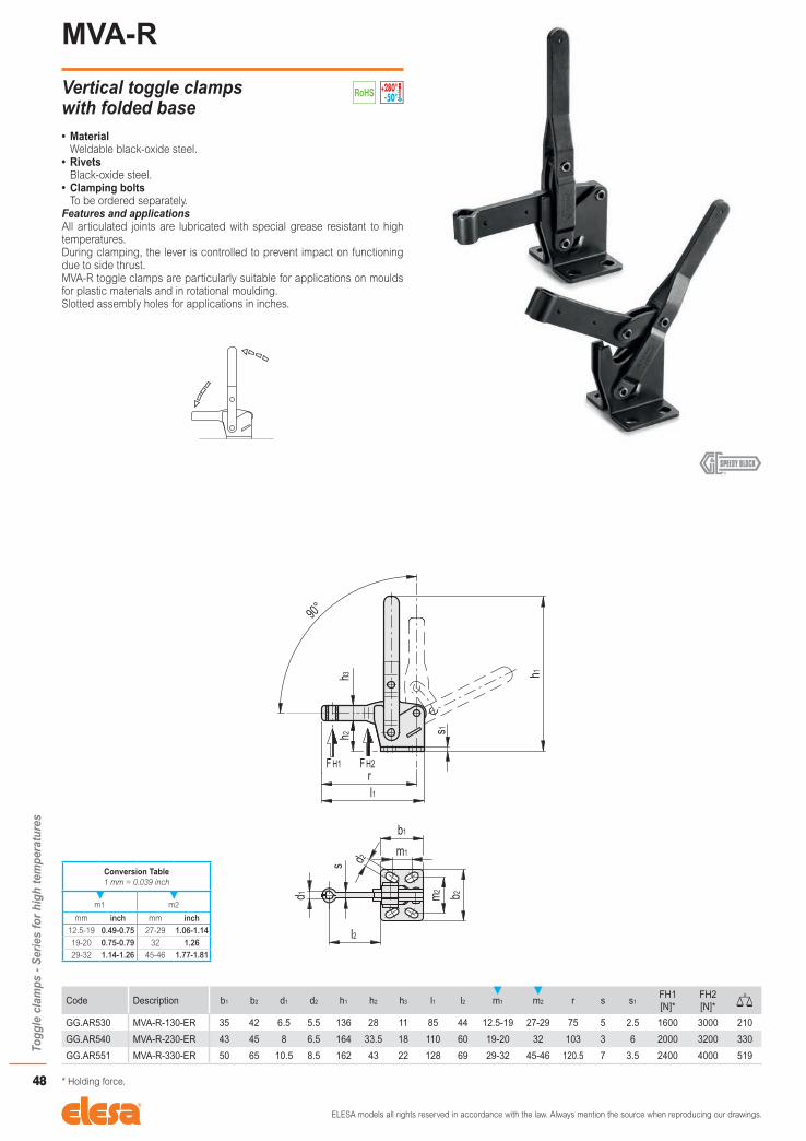
sMVA-R
Vertical toggle clamps with folded base• Material
Weldable black-oxide steel.• Rivets
Black-oxide steel.• Clamping bolts
To be ordered separately.Features and applicationsAll articulated joints are lubricated with special grease resistant to high temperatures.During clamping, the lever is controlled to prevent impact on functioning due to side thrust.MVA-R toggle clamps are particularly suitable for applications on moulds for plastic materials and in rotational moulding.Slotted assembly holes for applications in inches.
Code Description b1 b2 d1 d2 h1 h2 h3 l1 l2 m1 m2 r s s1FH1 [N]*
FH2 [N]*
GG.AR530 MVA-R-130-ER 35 42 6.5 5.5 136 28 11 85 44 12.5-19 27-29 75 5 2.5 1600 3000 210
GG.AR540 MVA-R-230-ER 43 45 8 6.5 164 33.5 18 110 60 19-20 32 103 3 6 2000 3200 330
GG.AR551 MVA-R-330-ER 50 65 10.5 8.5 162 43 22 128 69 29-32 45-46 120.5 7 3.5 2400 4000 519
* Holding force.
Conversion Table1 mm = 0.039 inch
m1 m2
mm inch mm inch12.5-19 0.49-0.75 27-29 1.06-1.1419-20 0.75-0.79 32 1.2629-32 1.14-1.26 45-46 1.77-1.81

ELESA models all rights reserved in accordance with the law. Always mention the source when reproducing our drawings.
49
Togg
le c
lam
ps -
Ser
ies
for
high
tem
pera
ture
s
MOA-R
Horizontal toggle clamps with folded base• Material
Weldable black-oxide steel.• Rivets
Black-oxide steel.• Clamping bolts
To be ordered separately.Features and applicationsAll articulated joints are lubricated with special grease resistant to high temperatures.A special feature of MOA-R toggle clamps is their low closure profile. During clamping, the lever is controlled to prevent impact on functioning due to side thrust.MOA-R toggle clamps are particularly suitable for applications on moulds for plastic materials and in rotational moulding.Slotted assembly holes for applications in inches.
Code Description b1 b2 d1 d2 h1 h2 h3 l l1 m1 m2 s s1FH1 [N]*
FH2 [N]*
GG.AR145 MOA-R-130-OR 36 40 5.5 6.5 51 29 14 48 162 26 26 5 2.5 1000 2000 185
GG.AR280 MOA-R-230-OR 44 42 8.5 6.5 61.5 36.5 18 56 190 26 28.5 6 3 1700 3300 300
GG.AR381 MOA-R-355-OR 60 56 10.5 8.5 83 50 22 89.5 260.5 41 41 7 3.5 1800 4000 700
* Holding force.
Conversion Table1 mm = 0.039 inch
m1 m2
mm inch mm inch26 1.02 26 1.0241 1.61 28.5 1.12
41 1.61

ELESA models all rights reserved in accordance with the law. Always mention the source when reproducing our drawings.
50
Togg
le c
lam
ps -
Ser
ies
for
high
tem
pera
ture
sMCR
Weldable latch clamps• Material
Weldable black-oxide steel.• Pins
Ground and hardened steel.Features and applicationsAll articulated joints are lubricated with special grease resistant to high temperatures.MCR toggle clamps are particularly suitable for applications on moulds for plastic materials and in rotational moulding.The position of the threaded screw can be adjusted according to specific applications.
Code Description B b1 b2 b3 d1 d2 H h1 h2 h3 L l1 l2 m1 m2 s s1FH [N]*
GG.AL758 MCR.1540 60 30 60 26 M10 8.5 280 168 40 71 173 54 32 15 45 8 5 1500 1110
GG.AL761 MCR.1576 60 30 60 26 M10 8.5 315 168 75 71 207 54 32 15 45 8 5 1500 1190
* Holding force.
Conversion Table1 mm = 0.039 inch
m2
mm inch45 1.77

ELESA models all rights reserved in accordance with the law. Always mention the source when reproducing our drawings.
51
Togg
le c
lam
ps -
Pne
umat
ic c
lam
ps
PFA.
Pneumatic clamps with push lever• Material
C10 zinc-plated steel.• Base
- Black coated brass, for size 70. - Black coated pressed steel, for sizes ≥360.
• RivetsZinc-plated steel.
• Hexagon-socket head screws with countersink for cylinder supportBlack-oxide steel.
• Cylinder support bushingHardened steel.
• Push leverZinc-plated steel.
• Rotating pin and seeger ringsHardened and ground steel (for sizes ≥360).
• Standard executions - PFA-SP3: with normal cylinder. - PFA-SPM: with magnetic cylinder.
• Maximum working pressure6 bars.
• Max working temperature80°C.
• Clamping boltsTo be ordered separately.
Features and applicationsAll articulated joints are lubricated with special grease.Execution PFA-SPM (with magnetic cylinder), equipped with limit switches type PSW. (see page 56) (to be ordered separately) gives drive and/or control impulses while active.Using a lubrication filter assembly is necessary for the cylinder to work properly for a long time, whereas flow regulators are recommended to guarantee long life of mechanical components.
PFA-SP3
Code Description a b1 d1 d2 d3 d4 h1 l1 l2 l3 m1 m2 m3 m4 s tStroke
wFH [N]*
FS [N]#
GG.AO350 PFA.70-SP3 14 42 8.5 M6 4.3 G1/8 51 171 64 20 26 13 - 26 8 12 12 1200 500 550
GG.AO361 PFA.360-SP3 27.5 55 12 M8 5.5 G1/8 72.5 260 116 32 33.5 30 - 36.5 9.5 15 22 5600 3100 1300
GG.AO371 PFA.1100-SP3 28 66 16 M10 8.5 G1/4 89 355 167 49 41 15 35 41 12 18 32 16000 4100 2400
GG.AO381 PFA.2100-SP3 38.5 81 20 M12 8.5 G1/4 100 461.5 232 61.5 50 35 50 50 13 22 45 25000 6070 5000
PFA-SPM
Code Description a b1 d1 d2 d3 d4 h1 l1 l2 l3 m1 m2 m3 m4 s tStroke
wFH [N]*
FS [N]#
GG.AO362 PFA.360-SPM 27.5 55 12 M8 5.5 G1/8 72.5 260 116 32 33.5 30 - 36.5 9.5 15 22 5600 3100 1300
GG.AO372 PFA.1100-SPM 28 66 16 M10 8.5 G1/4 89 355 167 49 41 15 35 41 12 18 32 16000 4100 2400
GG.AO382 PFA.2100-SPM 38.5 81 20 M12 8.5 G1/4 100 461.5 232 61.5 50 35 50 50 13 22 45 25000 6070 5000
* Holding force.# Clamping force ~4 bar
Conversion Table1 mm = 0.039 inch
m1 m3 m4
mm inch mm inch mm inch26 1.02 35 1.38 26 1.02
33.5 1.32 50 1.97 36.5 1.4441 1.61 41 1.6150 1.97 50 1.97

ELESA models all rights reserved in accordance with the law. Always mention the source when reproducing our drawings.
52
Togg
le c
lam
ps -
Pne
umat
ic c
lam
psPVA.
Pneumatic clamps• Material
C10 zinc-plated steel.• Rivets and pins
Zinc-plated steel.• Hexagon-socket head screws with countersink for cylinder support
Black-oxide steel.• Cylinder support bushings
Hardened steel.• Rotating pin and seeger rings
Hardened and ground steel (for sizes ≥200).• Standard executions
- PVA-AP3: with open clamping lever and two folded washers. - PVA-APM: with magnetic cylinder, open clamping lever and two folded washers.
- PVA-EP3: with solid clamping lever and retainer for welding. - PVA-EPM: with magnetic cylinder, solid clamping lever and retainer for welding.
• Maximum working pressure6 bars.
• Max working temperature80°C.
• Clamping boltsTo be ordered separately.
Features and applicationsAll articulated joints are lubricated with special grease.Functioning principles of PVA. pneumatic clamps are the same as MVA. manual toggle clamps.Executions PVA-APM and PVA-EPM (with magnetic cylinder), equipped with limit switches type PSW. (see page 56) (to be ordered separately) gives drive and/or control impulses while active.Using a lubrication filter assembly is necessary for the cylinder to work properly for a long time, whereas flow regulators are recommended to guarantee long life of mechanical components.
PVA-AP3
Code Description a b1 b2 d1 d2 d3 h1 h2 h3 h4 h5 l l1 l2 l3 m1 m2 m3 rFH1 [N]*
FH2 [N]*
FS1 [N]#
FS2 [N]#
GG.AO020 PVA.70-AP3 20 42 5.2 M5 4.5 G1/8 51.5 21 11 4 21 38 163 92 40 24 7 15 62.5 700 1450 500 750 500GG.AO041 PVA.125-AP3 23 47.5 6.2 M6 5.5 G1/8 70.5 30 14 4.5 27 50 200 150 48 29 8 19 79 1600 3000 700 1200 700GG.AO161 PVA.200-AP3 40 53 8.5 M8 6.5 G1/8 79 36 18 5.5 35 67.5 246 160 70 32 11 20 104 2200 3500 900 1500 1070GG.AO201 PVA.300-AP3 42 74 10.5 M10 8.5 G1/4 98 48 20 8.5 41 78.5 304.5 195.5 76 46 11 29 122 2700 4500 1200 2400 2100GG.AO301 PVA.400-AP3 66 74 12.5 M12 8.5 G1/4 107.5 51 22 10 48 110 360 216 104 45 10 32 156 3000 6400 1400 2600 3100
PVA-APM
GG.AO162 PVA.200-APM 40 53 8.5 M8 6.5 G1/8 79 36 18 5.5 35 67.5 246 160 70 32 11 20 104 2200 3500 900 1500 1070GG.AO202 PVA.300-APM 42 74 10.5 M10 8.5 G1/4 98 48 20 8.5 41 78.5 304.5 195.5 76 46 11 29 122 2700 4500 1200 2400 2100GG.AO302 PVA.400-APM 66 74 12.5 M12 8.5 G1/4 107.5 51 22 10 48 110 360 216 104 45 10 32 156 3000 6400 1400 2600 3100
PVA-EP3
Code Description b1 d1 d2 d3 h1 h2 h3 h4 l l1 l2 l4 m1 m2 m3 r sFH1 [N]*
FH2 [N]*
FS1 [N]#
FS2 [N]#
GG.AO025 PVA.70-EP3 42 M5 4.5 G1/8 51.5 21 11 4 38 163 92 48 24 7 15 62.5 4 700 1450 500 750 500GG.AO046 PVA.125-EP3 47.5 M6 5.5 G1/8 70.5 30 14 4.5 51 201 150 62 29 8 19 79 5 1600 3000 700 1200 700GG.AO166 PVA.200-EP3 53 M8 6.5 G1/8 79 36 18 5.5 69.5 248 160 86 32 11 20 104 6 2200 3500 900 1500 1070GG.AO206 PVA.300-EP3 74 M10 8.5 G1/4 98 48 20 8.5 80 306 195.5 95 46 11 29 122 8 2700 4500 1200 2400 2100GG.AO306 PVA.400-EP3 74 M12 8.5 G1/4 107.5 51 22 10 112 362 216 130 45 10 32 156 10 3000 6400 1400 2600 3100
PVA-EPM
GG.AO167 PVA.200-EPM 53 M8 6.5 G1/8 79 36 18 5.5 69.5 248 160 86 32 11 20 104 6 2200 3500 900 1500 1070GG.AO207 PVA.300-EPM 74 M10 8.5 G1/4 98 48 20 8.5 80 306 195.5 95 46 11 29 122 8 2700 4500 1200 2400 2100GG.AO307 PVA.400-EPM 74 M12 8.5 G1/4 107.5 51 22 10 112 362 216 130 45 10 32 156 10 3000 6400 1400 2600 3100
* Holding force.# Clamping force ~4 bar
Conversion Table1 mm = 0.039 inch
m1 m3
mm inch mm inch24 0.94 15 0.6029 1.14 19 0.7532 1.26 20 0.7946 1.81 29 1.1445 1.77 32 1.26

ELESA models all rights reserved in accordance with the law. Always mention the source when reproducing our drawings.
53
Togg
le c
lam
ps -
Pne
umat
ic c
lam
ps
PPC.
Pneumatic clamps Heavy-duty series• Material
Weldable zinc-plated steel.• Body
Black coated spheroidal cast iron.• Hexagon-socket head screws with countersink for cylinder support
Black-oxide steel.• Cylinder support bushings
Hardened steel.• Rotating pins and seeger rings
Ground and hardened steel.• Maximum working pressure
6 bars.• Max working temperature
80°C.Features and applicationsAll articulated joints are lubricated with special grease.PPC. pneumatic clamps are designed for easy disassembly. Indeed, rotation pins are fixed through seeger rings, which allows to disassemble and change the clamping lever to satisfy specific application requirements.The magnetic cylinder, equipped with limit switches type PSW. (see page 56) (to be ordered separately) gives drive and/or control impulses while active.Using a lubrication filter assembly is necessary for the cylinder to work properly for a long time, whereas flow regulators are recommended to guarantee long life of mechanical components.
Code Description b1 b2 b3 d1 d2 h1 h2 h3 h4 l l1 l2 m1 m2 m3 m4 rFH [N]*
FS [N]#
GG.AO600 PPC.1000-EPM 102 90 20 10.5 G1/4 146.5 80 25 13 80 410 155 65 12.5 65 48 140 10000 3200 6500
GG.AO620 PPC.2000-EPM 112 100 20 10.5 G3/8 171.5 90 35 13 100 487 176 70 15 70 56 172 20000 3800 9500
* Holding force.# Clamping force ~4 bar
Conversion Table1 mm = 0.039 inch
m1 m3
mm inch mm inch65 2.56 65 2.5670 2.75 70 2.75

ELESA models all rights reserved in accordance with the law. Always mention the source when reproducing our drawings.
54
Togg
le c
lam
ps -
Pne
umat
ic c
lam
psPVC.
Pneumatic clamps with toggle-joint support• Material
C10 zinc-plated steel.• Rivets and pins
Zinc-plated steel.• Hexagon-socket head screws with countersink for cylinder support
Black-oxide steel.• Cylinder support bushing
Hardened steel.• Rotating pin and seeger rings
Hardened steel.• Standard executions
- PVC-APV3: with open clamping lever and two folded washers. - PVC-APVM: with magnetic cylinder, open clamping lever and two folded washers.
- PVC-EPV3: with solid clamping lever retainer for welding. - PVC-EPVM: with magnetic cylinder, solid clamping lever and retainer for welding.
• Maximum working pressure6 bars.
• Max working temperature80°C.
• Clamping boltsTo be ordered separately.
Features and applicationsAll articulated joints are lubricated with special grease.PVC. pneumatic clamps can be installed on two different fixing surfaces.Executions PVC-APVM and PVC-EPVM (with magnetic cylinder), equipped with limit switches type PSW. (see page 56) (to be ordered separately) gives drive and/or control impulses while active.Using a lubrication filter assembly is necessary for the cylinder to work properly for a long time, whereas flow regulators are recommended to guarantee long life of mechanical components.
PVC-APV3
Code Description a b1 b2 b3 b4 d1 d2 d3 h1 h2 h3 h4 h5 l l1 l2 m1 m2 m3 m4 rFH1 [N]*
FH2 [N]*
FS1 [N]#
FS2 [N]#
GG.AO181 PVC.200-APV3 34 59.5 51 35 8.5 M8 6.5 G1/8 210 78 17 3 35 55 149 59 26 14.5 16 16 98 1200 2400 900 1500 1200GG.AO221 PVC.300-APV3 42 68.5 60.5 50 10.3 M10 8.5 G1/4 258 108 20 3 41 71 186 74 30 16.5 28 30 122 1900 2000 1200 2400 2450
PVC-APVM
GG.AO182 PVC.200-APVM 34 59.5 51 35 8.5 M8 6.5 G1/8 210 78 17 3 35 55 149 59 26 14.5 16 16 98 1200 2400 900 1500 1200GG.AO222 PVC.300-APVM 42 68.5 60.5 50 10.3 M10 8.5 G1/4 258 108 20 3 41 71 186 74 30 16.5 28 30 122 1900 2000 1200 2400 2450
PVC-EPV3
Code Description b1 b2 b3 d1 d2 d3 h1 h2 h3 h4 l l1 l3 m1 m2 m3 m4 r sFH1 [N]*
FH2 [N]*
FS1 [N]#
FS2 [N]#
GG.AO186 PVC.200-EPV3 59.5 51 35 M8 6.5 G1/8 210 78 17 3 57 151 80 26 14.5 16 16 98 6 1200 2400 900 1500 1200GG.AO226 PVC.300-EPV3 68.5 60.5 50 M10 8.5 G1/4 258 108 20 3 72.5 187.5 104 30 16.5 28 30 122 8 1900 2000 1200 2400 2450
PVC-EPVM
GG.AO187 PVC.200-EPVM 59.5 51 35 M8 6.5 G1/8 210 78 17 3 57 151 80 26 14.5 16 16 98 6 1200 2400 900 1500 1200GG.AO227 PVC.300-EPVM 68.5 60.5 50 M10 8.5 G1/4 258 108 20 3 72.5 187.5 104 30 16.5 28 30 122 8 1900 2000 1200 2400 2450
* Holding force.# Clamping force ~4 bar
Conversion Table1 mm = 0.039 inch
m1 m3 m4
mm inch mm inch mm inch26 1.02 16 0.63 16 0.6330 1.18 28 1.10 30 1.18

ELESA models all rights reserved in accordance with the law. Always mention the source when reproducing our drawings.
55
Togg
le c
lam
ps -
Pne
umat
ic c
lam
ps
PPD.
Pneumatic clamps Heavy-duty series• Material
Weldable zinc-plated steel.• Body
Black coated spheroidal cast iron.• Hexagon-socket head screws with countersink for cylinder support
Hardened steel.• Cylinder support bushings
Hardened steel.• Rotating pins and seeger rings
Ground and hardened steel.• Maximum working pressure
6 bars.• Max working temperature
80°C.Features and applicationsAll articulated joints are lubricated with special grease.PPD. pneumatic clamps are designed for easy disassembly. Indeed, rotation pins are fixed through seeger rings, which allows to disassemble and change the clamping lever to satisfy specific application requirements.The magnetic cylinder, equipped with limit switches type PSW. (see page 56) (to be ordered separately) gives drive and/or control impulses while active.Using a lubrication filter assembly is necessary for the cylinder to work properly for a long time, whereas flow regulators are recommended to guarantee long life of mechanical components.
Code Description b1 b2 b3 b4 d1 d2 h1 h2 h3 l1 l2 m1 m2 m3 m4 r sFH [N]*
FS [N]#
GG.AO605 PPD.1000-EPVM 102 90 80 20 10.5 G1/4 355 130 25 215 80 50 50 - - 144 13 10000 3400 6500
GG.AO625 PPD.2000-EPVM 112 100 90 20 13 G3/8 424 157 35 246.5 100 54 58 45 45 168.5 14 20000 4320 9000
* Holding force.# Clamping force ~4 bar
Conversion Table1 mm = 0.039 inch
m1 m2 m3 m4
mm inch mm inch mm inch mm inch50 1.97 50 1.97 45 1.77 45 1.7754 2.12 58 2.28

ELESA models all rights reserved in accordance with the law. Always mention the source when reproducing our drawings.
56
Togg
le c
lam
ps -
Acc
esso
ries
PSW.
Limit switches with holding bracket• Electrical features
- Voltage range: 3÷110 V AC/DC - Voltage drop LED: 3 V - Temperature range: -20°C +85°C - Life expectancy: (operations) 107
- Protection classification: IP 67 - Cable length: 2.5 mt
Features and applicationsPSW. limit switches detect magnetic fields through electrical impulses. The pneumatic magnetic series features tools equipped with magnetic cylinders that deliver drive and/or control electrical impulses with the limit switches provided. As they feature luminous leds, the min. use voltage is 3V and voltage drop will be 3V each if they are series connected.Using a very long connection cable (over 5 m) could impact proper functioning of the sensor due to the high capacity value which is directly proportional to the cable length. In such conditions, it is recommended to use an inductor to eliminate the effects of cable capacity.In direct current circuits, always connect the brown wire to the positive pole.It is recommended to keep electrical cables and large ferrous masses at due distance as the latter could disturb the sensor due to the effects of mutual induction.Sensors can detect signals at a speed of 1 m/s.Using a holding bracket, they can be positioned all along the cylinder stroke.
Code DescriptionCurrent on
contactSwitch
capacitySlew rate PVA PVC PPC PPD PFA
GG.AU460 PSW.32-40 0.3 A 10 VA 1.97 ft/s (0.6 ms) 90PVA.200-APM/EPM PVA.300-APM/EPM
PVC.200-APVM/EPVM PVC.300-APVM/EPVM
- -PFA.360-SPM PFA.1100-SPM
GG.AU450 PSW.50 0.3 A 10 VA 1.97 ft/s (0.6 ms) 85 PVA.400-APM/EPM - - - PFA.2100-SPM
GG.AU470 PSW.50-63-MW 0.2 A 6 VA 1.64 ft/s (0.5 ms) 40 - -PPC.1000-EPM PPC.2000-EPM
PPD.1000-EPVM PPD.2000-EPVM
-

ELESA models all rights reserved in accordance with the law. Always mention the source when reproducing our drawings.
57
Togg
le c
lam
ps -
Acc
esso
ries
SAH.
Clamping bolts• Base
Zinc-plated steel.• Threaded stem
Zinc-plated steel.• Nuts
Zinc-plated steel.
Code Description d d1 h l
GG.AU120 SAH.M5x36 M5 14 9.5 36 10
GG.AU121 SAH.M6x45 M6 16 10 45 17
GG.AU122 SAH.M8x65 M8 18 12 65 30
GG.AU123 SAH.M10x75 M10 20 14 75 56
GG.AU124 SAH.M12x85 M12 24 16 85 47
GG.AU125 SAH.M12x125 M12 24 16 125 95
SAH-SST
Clamping bolts• Base
AISI 304 stainless steel.• Threaded stem
AISI 304 stainless steel.• Nuts
AISI 304 stainless steel.
Code Description d d1 h l
GG.AU520 SAH-SST-M5x36 M5 14 9.5 36 10
GG.AU521 SAH-SST-M6x45 M6 16 10 45 17
GG.AU522 SAH-SST-M8x65 M8 18 12 65 30

ELESA models all rights reserved in accordance with the law. Always mention the source when reproducing our drawings.
58
Togg
le c
lam
ps -
Acc
esso
ries
SRH.
Clamping bolts• Material
Zinc-plated steel.• Base
Black neoprene, hardness 85 Shore A.• Nuts
Zinc-plated steel.
Code Description d d1 h l
GG.AU140 SRH.M5x45 M5 10 11 45 9
GG.AU141 SRH.M6x55 M6 13 12 55 16
GG.AU142 SRH.M8x68 M8 16 16 68 33
GG.AU143 SRH.M10x80 M10 20 20 80 64
SRH-SST
Clamping bolts• Material
AISI 304 stainless steel.• Base
Black neoprene, hardness 85 Shore A.• Nuts
AISI 304 stainless steel.
Code Description d d1 h l
GG.AU540 SRH-SST-M5x45 M5 10 11 45 9
GG.AU541 SRH-SST-M6x55 M6 13 12 55 16
GG.AU542 SRH-SST-M8x68 M8 16 16 68 33
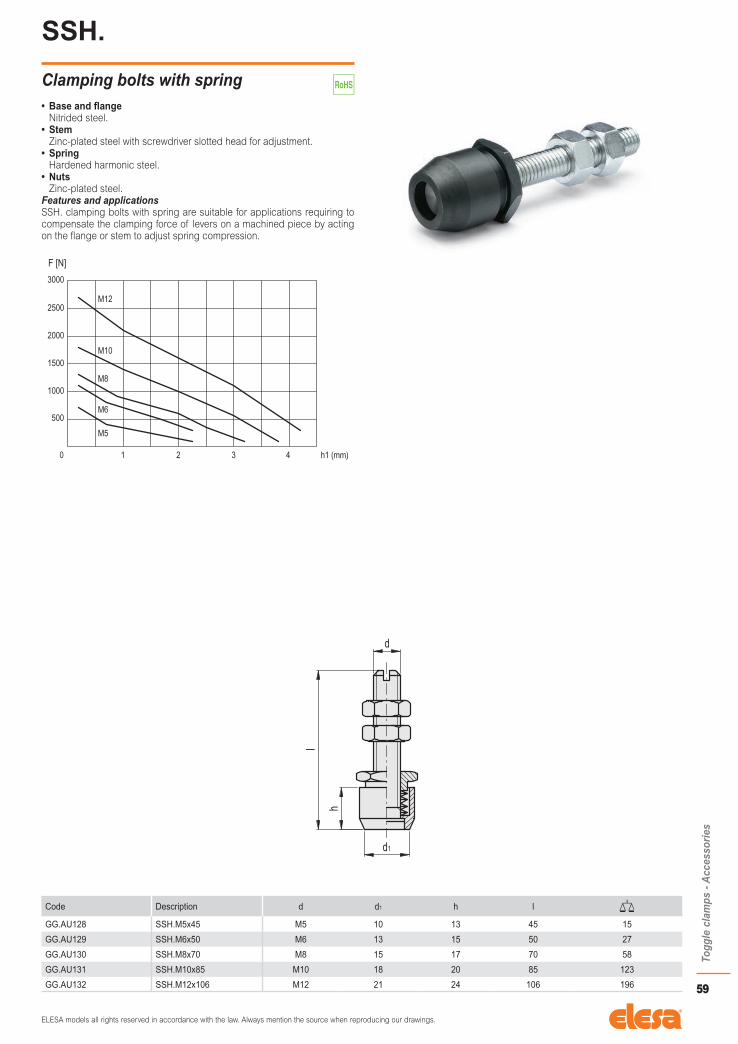
ELESA models all rights reserved in accordance with the law. Always mention the source when reproducing our drawings.
59
Togg
le c
lam
ps -
Acc
esso
ries
SSH.
Clamping bolts with spring• Base and flange
Nitrided steel.• Stem
Zinc-plated steel with screwdriver slotted head for adjustment.• Spring
Hardened harmonic steel.• Nuts
Zinc-plated steel.Features and applicationsSSH. clamping bolts with spring are suitable for applications requiring to compensate the clamping force of levers on a machined piece by acting on the flange or stem to adjust spring compression.
Code Description d d1 h l
GG.AU128 SSH.M5x45 M5 10 13 45 15
GG.AU129 SSH.M6x50 M6 13 15 50 27
GG.AU130 SSH.M8x70 M8 15 17 70 58
GG.AU131 SSH.M10x85 M10 18 20 85 123
GG.AU132 SSH.M12x106 M12 21 24 106 196

ELESA models all rights reserved in accordance with the law. Always mention the source when reproducing our drawings.
60
Togg
le c
lam
ps -
Acc
esso
ries
SHH.
Clamping bolts• Material
Zinc-plated steel.• Nuts
Zinc-plated steel.
Code Description d h l
GG.AU099 SHH.M4x20 M4 3 20 5
GG.AU100 SHH.M5x35 M5 3 35 9
GG.AU101 SHH.M6x45 M6 3.5 45 15
GG.AU102 SHH.M8x55 M8 4 55 30
GG.AU103 SHH.M10x65 M10 5.5 65 48
GG.AU104 SHH.M12x80 M12 7 80 80
GG.AU105 SHH.M12x120 M12 8 120 115
SHH-SST
Clamping bolts• Material
AISI 304 stainless steel.• Nuts
AISI 304 stainless steel.
Code Description d h l
GG.AU509 SHH.SST-M4x20 M4 3 20 5
GG.AU510 SHH.SST-M5x35 M5 3 35 9
GG.AU511 SHH.SST-M6x45 M6 3.5 45 15
GG.AU512 SHH.SST-M8x55 M8 4 55 30

ELESA models all rights reserved in accordance with the law. Always mention the source when reproducing our drawings.
61
Togg
le c
lam
ps -
Acc
esso
ries
NCH.
Caps for clamping bolts• Material
Black neoprene, hardness 85 Shore A.ApplicationsNCH. caps are designed to optimize use of clamping bolts.
Code Description D h h1 For plunger
GG.AU109 NCH.11-M4 11 6.5 4 1 SHH.M4
GG.AU110 NCH.12-M5 12 8 5.5 1 SHH.M5
GG.AU111 NCH.15-M6 15 10 6 2 SHH.M6
GG.AU112 NCH.19-M8 19 13 7.5 4 SHH.M8
GG.AU113 NCH.24-M10 24 16 9 7 SHH.M10
GG.AU114 NCH.26-M12 26 19 10.5 9 SHH.M12
NCN.
Caps for clamping bolts with threaded insert• Material
Black neoprene, hardness 85 Shore A.• Threaded insert
Zinc-plated steel.ApplicationsNCN. caps with threaded insert are designed to optimize use of clamping bolts.
Code Description D h h1 For plunger
GG.AU200 NCN.12-M5 12 11 8.5 4 M5
GG.AU201 NCN.15-M6 15 14 10 8 M6
GG.AU202 NCN.19-M8 19 18 12.3 17 M8
GG.AU203 NCN.24-M10 24 23.5 16.5 20 M10
GG.AU204 NCN.26-M12 26 26 17.5 25 M12

62
Num
eric
al in
dex
CODE DESCRIPTION PAGE
GG.AA220 MVC.200-AV 10
GG.AA221 MVD.200-AVF 11
GG.AA225 MVC.200-EV 10
GG.AA226 MVD.200-EVF 11
GG.AA320 MVC.300-AV 10
GG.AA321 MVD.300-AVF 11
GG.AA325 MVC.300-EV 10
GG.AA326 MVD.300-EVF 11
GG.AA520 MVA.75-A 6
GG.AA522 MVB.75-B 8
GG.AA524 MVA.75-E 7
GG.AA526 MVB.75-F 9
GG.AA530 MVA.130-A 6
GG.AA532 MVB.130-B 8
GG.AA534 MVA.130-E 7
GG.AA536 MVB.130-F 9
GG.AA540 MVA.230-A 6
GG.AA542 MVB.230-B 8
GG.AA544 MVA.230-E 7
GG.AA546 MVB.230-F 9
GG.AA550 MVA.330-A 6
GG.AA552 MVB.330-B 8
GG.AA554 MVA.330-E 7
GG.AA556 MVB.330-F 9
GG.AA560 MVA.430-A 6
GG.AA562 MVB.430-B 8
GG.AA564 MVA.430-E 7
GG.AA566 MVB.430-F 9
GG.AA570 MVA.530-A 6
GG.AA572 MVB.530-B 8
GG.AA574 MVA.530-E 7
GG.AA576 MVB.530-F 9
GG.AA600 MVA.LLA01 13
GG.AA605 MVB.LLB01 14
GG.AA610 MVA.LLE01 13
GG.AA615 MVB.LLF01 14
GG.AA630 MVA.LLA02 13
GG.AA635 MVB.LLB02 14
GG.AA640 MVA.LLE02 13
GG.AA645 MVB.LLF02 14
GG.AA660 MVA.LLE03 13
GG.AA665 MVB.LLF03 14
GG.AA680 MVA.LLE04 13
GG.AA685 MVB.LLF04 14
GG.AA700 MGA.LSC01 15
GG.AA705 MGB.LSG01 16
GG.AA710 MGC.LSH01 17
GG.AA725 MGA.LSC02 15
GG.AA730 MGB.LSG02 16
GG.AA735 MGC.LSH02 17
GG.AA750 MGA.LSC03 15
GG.AA755 MGB.LSG03 16
GG.AA760 MGC.LSH03 17
GG.AA775 MGA.LSC04 15
CODE DESCRIPTION PAGE
GG.AA780 MGB.LSG04 16
GG.AA785 MGC.LSH04 17
GG.AA900 MPB.1000-F 12
GG.AA905 MPB.2000-F 12
GG.AA910 MPB.3000-F 12
GG.AD025 MOA.25-M 20
GG.AD075 MOA.75-M 20
GG.AD076 MOC.75-MF 19
GG.AD080 MOB.75-N 22
GG.AD085 MOA.75-O 20
GG.AD090 MOB.75-P 22
GG.AD135 MOA.130-M 20
GG.AD136 MOC.130-MF 19
GG.AD140 MOB.130-N 22
GG.AD145 MOA.130-O 20
GG.AD150 MOB.130-P 22
GG.AD270 MOA.230-M 20
GG.AD271 MOC.230-MF 19
GG.AD275 MOB.230-N 22
GG.AD280 MOA.230-O 20
GG.AD285 MOB.230-P 22
GG.AD370 MOA.355-M 20
GG.AD371 MOC.355-MF 19
GG.AD375 MOB.355-N 22
GG.AD380 MOA.355-O 20
GG.AD385 MOB.355-P 22
GG.AD470 MOA.455-M 20
GG.AD475 MOB.455-N 22
GG.AD480 MOA.455-O 20
GG.AD485 MOB.455-P 22
GG.AG050 MLA.50-ASD 24
GG.AG055 MLA.50-ASS 24
GG.AG070 MFC.70-AS 27
GG.AG075 MLB.70-ASD 25
GG.AG080 MLB.70-ASS 25
GG.AG120 MFA.120-AS 26
GG.AG160 MFC.160-AS 27
GG.AG165 MLB.160-ASD 25
GG.AG170 MLB.160-ASS 25
GG.AG300 MFA.300-AS 26
GG.AG351 MFC.360-AS 27
GG.AG355 MFC.550-AS 27
GG.AG361 MFC.1100-AS 27
GG.AG371 MFC.2100-AS 27
GG.AG381 MFC.3100-AS 27
GG.AG401 MFE.80-AS 28
GG.AG406 MFE.165-AS 28
GG.AG411 MFE.340-AS 28
GG.AG416 MFE.30080 28
GG.AG421 MFE.30165 28
GG.AG426 MFE.30340 28
CODE DESCRIPTION PAGE
GG.AL200 MTA.200-T 39
GG.AL205 MTA.200-TF 39
GG.AL300 MTA.300-T 39
GG.AL305 MTA.300-TF 39
GG.AL400 MTA.400-T 39
GG.AL405 MTA.400-TF 39
GG.AL500 MTC.160-T2 34
GG.AL505 MTC.320-T2 34
GG.AL510 MTC.700-T2 34
GG.AL530 MTD.160-T3 36
GG.AL535 MTD.320-T3 36
GG.AL540 MTD.700-T3 36
GG.AL550 MTP-D-1400-T3 45
GG.AL552 MTS-D-1400-T3S 46
GG.AL560 MTE.160-T4 38
GG.AL565 MTE.320-T4 38
GG.AL570 MTE.700-T4 38
GG.AL575 MTB.160-T5 30
GG.AL576 MTB.160-T5-TG 31
GG.AL577 MTB.160-T5-TU 31
GG.AL578 MTB.160-T5-TT 31
GG.AL580 MTB.320-T5 30
GG.AL581 MTB.320-T5-TG 31
GG.AL582 MTB.320-T5-TU 31
GG.AL583 MTB.320-T5-TT 31
GG.AL585 MTB.700-T5 30
GG.AL586 MTB.700-T5-TG 31
GG.AL587 MTB.700-T5-TU 31
GG.AL588 MTB.700-T5-TT 31
GG.AL590 MTL.1400-T5 44
GG.AL600 MTP.1400-T2 40
GG.AL610 MTP.2800-T2 40
GG.AL620 MTS.1400-T2S 42
GG.AL630 MTS.2800-T2S 42
GG.AL750 MTR.1500-T2S 47
GG.AL755 MTR.1510-T2S 47
GG.AL758 MCR.1540 50
GG.AL760 MCR.1575 50
GG.AO020 PVA.70-AP3 52
GG.AO025 PVA.70-EP3 52
GG.AO041 PVA.125-AP3 52
GG.AO046 PVA.125-EP3 52
GG.AO161 PVA.200-AP3 52
GG.AO162 PVA.200-APM 52
GG.AO166 PVA.200-EP3 52
GG.AO167 PVA.200-EPM 52
GG.AO181 PVC.200-APV3 54
GG.AO182 PVC.200-APVM 54
GG.AO186 PVC.200-EPV3 54
GG.AO187 PVC.200-EPVM 54
GG.AO201 PVA.300-AP3 52
GG.AO202 PVA.300-APM 52
GG.AO206 PVA.300-EP3 52
CODE DESCRIPTION PAGE
GG.AO207 PVA.300-EPM 52
GG.AO221 PVC.300-APV3 54
GG.AO222 PVC.300-APVM 54
GG.AO226 PVC.300-EPV3 54
GG.AO227 PVC.300-EPVM 54
GG.AO301 PVA.400-AP3 52
GG.AO302 PVA.400-APM 52
GG.AO306 PVA.400-EP3 52
GG.AO307 PVA.400-EPM 52
GG.AO350 PFA.70-SP3 51
GG.AO361 PFA.360-SP3 51
GG.AO362 PFA.360-SPM 51
GG.AO371 PFA.1100-SP3 51
GG.AO372 PFA.1100-SPM 51
GG.AO381 PFA.2100-SP3 51
GG.AO382 PFA.2100-SPM 51
GG.AO600 PPC.1000-EPM 53
GG.AO605 PPD.1000-EPVM 55
GG.AO620 PPC.2000-EPM 53
GG.AO625 PPD.2000-EPVM 55
GG.AR145 MOA-R-130-OR 49
GG.AR280 MOA-R-230-OR 49
GG.AR380 MOA-R-355-OR 49
GG.AR530 MVA-R-130-ER 48
GG.AR540 MVA-R-230-ER 48
GG.AR550 MVA-R-330-ER 48
GG.AS095 MVA.75-AX 7
GG.AS100 MVB.75-BX 9
GG.AS105 MVA.75-EX 7
GG.AS110 MVB.75-FX 9
GG.AS150 MVA.130-AX 7
GG.AS155 MVB.130-BX 9
GG.AS160 MVA.130-EX 7
GG.AS165 MVB.130-FX 9
GG.AS180 MVA.230-AX 7
GG.AS185 MVB.230-BX 9
GG.AS190 MVA.230-EX 7
GG.AS195 MVB.230-FX 9
GG.AS401 MFE.80-ASX 29
GG.AS406 MFE.165-ASX 29
GG.AS411 MFE.340-ASX 29
GG.AS416 MFE.30080X 29
GG.AS421 MFE.30165X 29
GG.AS426 MFE.30340X 29
GG.AS500 MTC.160-T2X 35
GG.AS505 MTC.320-T2X 35
GG.AS510 MTC.700-T2X 35
GG.AS530 MTD.160-T3X 37
GG.AS535 MTD.320-T3X 37
GG.AS540 MTD.700-T3X 37
GG.AS545 MTB.160-T5X 32
GG.AS546 MTB.160-T5X-TG 33
NUMERICAL INDEX

63
Alp
habe
tical
inde
x
NUMERICAL INDEX
CODE DESCRIPTION PAGE
GG.AS547 MTB.160-T5X-TU 33
GG.AS548 MTB.160-T5X-TT 33
GG.AS550 MTB.320-T5X 32
GG.AS551 MTB.320-T5X-TG 33
GG.AS552 MTB.320-T5X-TU 33
GG.AS553 MTB.320-T5X-TT 33
GG.AS555 MTB.700-T5X 32
GG.AS556 MTB.700-T5X-TG 33
GG.AS557 MTB.700-T5X-TU 33
GG.AS558 MTB.700-T5X-TT 33
GG.AS580 MTP.1400-T2X 41
GG.AS585 MTP.2800-T2X 41
GG.AS590 MTS.1400-T2SX 43
GG.AS595 MTS.2800-T2SX 43
GG.AU099 SHH.M4x20 60
GG.AU100 SHH.M5x35 60
GG.AU101 SHH.M6x45 60
GG.AU102 SHH.M8x55 60
GG.AU103 SHH.M10x65 60
GG.AU104 SHH.M12x80 60
GG.AU105 SHH.M12x120 60
GG.AU109 NCH.11-M4 61
GG.AU110 NCH.12-M5 61
GG.AU111 NCH.15-M6 61
GG.AU112 NCH.19-M8 61
GG.AU113 NCH.24-M10 61
GG.AU114 NCH.26-M12 61
GG.AU120 SAH.M5x36 57
GG.AU121 SAH.M6x45 57
GG.AU122 SAH.M8x65 57
GG.AU123 SAH.M10x75 57
GG.AU124 SAH.M12x85 57
GG.AU125 SAH.M12x125 57
GG.AU128 SSH.M5x45 59
GG.AU129 SSH.M6x50 59
GG.AU130 SSH.M8x70 59
GG.AU131 SSH.M10x85 59
GG.AU132 SSH.M12x106 59
GG.AU140 SRH.M5x45 58
GG.AU141 SRH.M6x55 58
GG.AU142 SRH.M8x68 58
GG.AU143 SRH.M10x80 58
GG.AU151 ALL.I-55 18
GG.AU154 ALL.I-77 18
GG.AU156 ALL.I-112 18
GG.AU157 ALL.I-112/25 18
GG.AU200 NCN.12-M5 61
GG.AU201 NCN.15-M6 61
GG.AU202 NCN.19-M8 61
GG.AU203 NCN.24-M10 61
GG.AU204 NCN.26-M12 61
GG.AU230 ALL.LS01 18
GG.AU235 ALL.LS02 18
CODE DESCRIPTION PAGE
GG.AU240 ALL.LS03 18
GG.AU245 ALL.LS04 18
GG.AU250 ALL.LC01 18
GG.AU255 ALL.LC02 18
GG.AU260 ALL.LC03 18
GG.AU265 ALL.LC04 18
GG.AU280 ALL.LM01 18
GG.AU285 ALL.LM02 18
GG.AU290 ALL.LM03 18
GG.AU295 ALL.LM04 18
GG.AU300 ALL.PB01 18
GG.AU305 ALL.PB02 18
GG.AU310 ALL.PB03 18
GG.AU315 ALL.PB04 18
GG.AU450 PSW.50 56
GG.AU460 PSW.32-40 56
GG.AU470 PSW.50-63-MW 56
GG.AU509 SHH.SST-M4x20 60
GG.AU510 SHH.SST-M5x35 60
GG.AU511 SHH.SST-M6x45 60
GG.AU512 SHH.SST-M8x55 60
GG.AU520 SAH-SST-M5x36 57
GG.AU521 SAH-SST-M6x45 57
GG.AU522 SAH-SST-M8x65 57
GG.AU540 SRH-SST-M5x45 58
GG.AU541 SRH-SST-M6x55 58
GG.AU542 SRH-SST-M8x68 58
GG.DS025 MOA.25-MX 21
GG.DS075 MOA.75-MX 21
GG.DS076 MOC.75-MFX 19
GG.DS080 MOB.75-NX 23
GG.DS085 MOA.75-OX 21
GG.DS090 MOB.75-PX 23
GG.DS135 MOA.130-MX 21
GG.DS136 MOC.130-MFX 19
GG.DS140 MOB.130-NX 23
GG.DS145 MOA.130-OX 21
GG.DS150 MOB.130-PX 23
GG.DS270 MOA.230-MX 21
GG.DS271 MOC.230-MFX 19
GG.DS275 MOB.230-NX 23
GG.DS280 MOA.230-OX 21
GG.DS285 MOB.230-PX 23
GG.DS140 MOB.130-NX 23
GG.DS145 MOA.130-OX 21
GG.DS150 MOB.130-PX 23
GG.DS270 MOA.230-MX 21
GG.DS271 MOC.230-MFX 24
GG.DS275 MOB.230-NX 23
GG.DS280 MOA.230-OX 21
GG.DS285 MOB.230-PX 23
ALPHABETICAL INDEX
TYPE PAGE
A
ALL. 18
M
MCR 50
MFA. 26
MFC. 27
MFE. 28
MFE-SST 29
MGA.L 15
MGB.L 16
MGC.L 17
MLA. 24
MLB. 25
MOA. 20
MOA-R 49
MOA-SST 21
MOB. 22
MOB-SST 23
MOC. 19
MPB. 12
MTA. 39
MTB. 30
MTB-SST 32
MTC. 34
MTC-SST 35
MTD. 36
MTD-SST 37
MTE. 38
MTL. 44
MTP. 40
MTP-D 45
MTP-SST 41
MTR. 47
MTS. 42
MTS-D 46
MTS-SST 43
MVA. 6
MVA.L 13
MVA-R 48
MVB. 8
MVB.L 14
MVC. 10
MVD. 11
N
NCH. 61
NCN. 61
TYPE PAGE
P
PFA. 51
PPC. 53
PPD. 55
PSW. 56
PVA. 52
PVC. 54
S
SAH. 57
SAH-SST 57
SHH. 60
SHH-SST 60
SRH. 58
SRH-SST 58
SSH. 59

64
© COPYRIGHT ELESA 2015
All rights reserved.No part of this catalogue can be reproduced in whole or in partwithout prior written permission from ELESA S.p.A. Printed in Italy
ZC
ATO
GC
LAM
PAM
15
www.elesa.com
Toggle clampsELESA USA Corporation
1930 Case Parkway N. Twinsburg, Ohio 44087
Phone: +1 330 4051300 Toll Free: 800 374 7686
Fax: +1 330 4051310www.elesausa.com
Top Related