


Languages
Pages
Legal


Evolutionary Algorithmsin Test Generation for digital systems
Y.A.Skobtsov,V.Y.Skobtsov
2
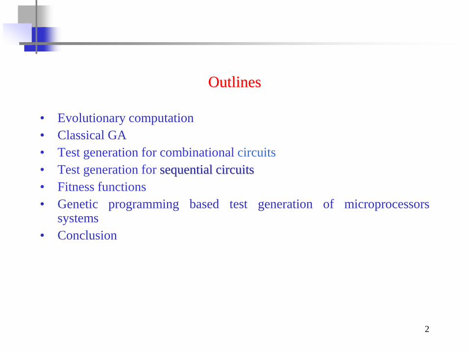
Outlines
• Evolutionary computation
• Classical GA
• Test generation for combinational circuits
• Test generation for sequential circuits
• Fitness functions
• Genetic programming based test generation of microprocessorssystems
• Conclusion

3
Evolutionary computation
Basic paradigms:
❖ Genetic algorithms
❖ Genetic programming
❖ Evolutionary strategies
All basic paradigms can be applied in ATPG problem solving

4
A flowchart of classical GA
Initial population generation
Selecting parents for crossover operator –
reproduction operator
Creating offsprings of selected pairs of
parents – crossover operator
Mutation of created individuals –
mutation operator
Insertion of new individuals to the current
population
Reducing the number of individuals to
given number in new population by
application of reproduction operator
Search of the best individual in final
population
Final criterion
checking – Yes/No?
Yes
No

5
Evolutionary test generation
For solving any problem with genetic algorithm we must define:
1) individual and population;
2) genetic operators;
3) fitness function.
Genetic Algorithm
Population,
individual
Genetic
operators
Fitness
function
&
EWDTW'06 , Sochi, Russia, September 15-19, 2006
6
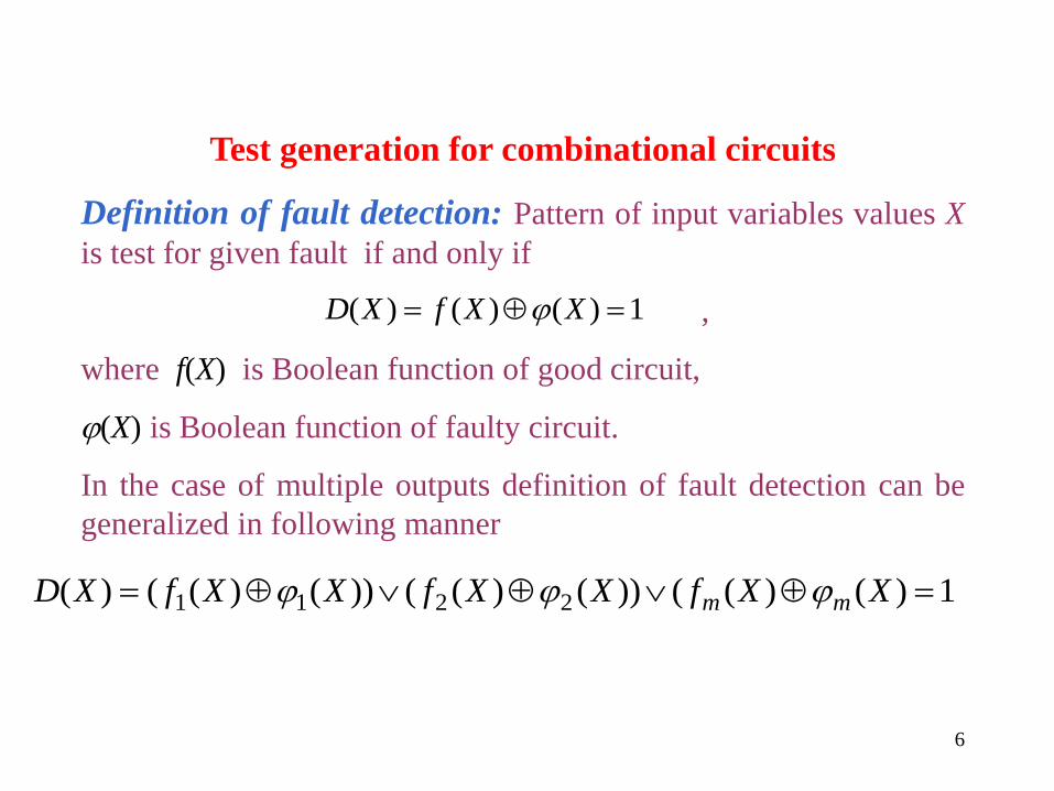
Test generation for combinational circuits
Definition of fault detection: Pattern of input variables values X
is test for given fault if and only if
,
where f(X) is Boolean function of good circuit,
(X) is Boolean function of faulty circuit.
In the case of multiple outputs definition of fault detection can be
generalized in following manner
1)()()( XXfXD
1)()(())()(())()(()( 2211 XXfXXfXXfXD mm

Combinational circuits
7
x4
x5
x1
x2
x3
x6
Table 13.1.
X1 X2 X3 X4 X5 X6
0 0 0 1 1 1
0 0 1 1 1 1
0 1 0 1 1 1
0 1 1 1 0 0
1 0 0 1 1 1
1 0 1 1 0 0
1 1 0 0 1 0
1 1 1 0 1 0
Table 13.2
Input vector
(x1, x2, x3,)
Detected
faults
Fitness function
value
h= Fn *r
000 x4 = 0, x5 =0,
x6=0
310
011 x2=0, x3=0,
x5 =1, x6=1 410
101 x2=1, x4=0,
x5 =0, x6=0 410
111 x6=1 110

8
Test Generation Genetic AlgorithmTest generation(circuit)
{
Circuit initialization;
Initial vectors population generation;
While(stopping criteria met)
{
fault simulation;
fitness function evaluation;
insertion the best vector in test;
genetic operators execution;
reproduction;
crossover;
mutation;
new population generation;
}
test sequence output;
}

9
Individuals encoding & crossover schemas for:
a) combinational circuits test generation:
b) sequential circuits test generation:
b) population
Mutation schemas:
a) deleting one randomly located input pattern
b) adding one input pattern to random position
c) random bit inversion in test sequence
10
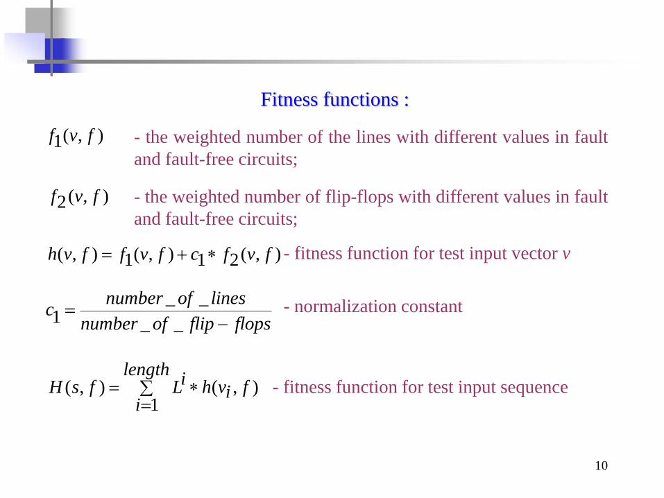
Fitness functions :
- the weighted number of the lines with different values in fault
and fault-free circuits;
),(1 fvf
- the weighted number of flip-flops with different values in fault
and fault-free circuits;
),(2 fvf
- fitness function for test input vector v),(21),(1),( fvfcfvffvh
flopsflipofnumber
linesofnumberc
__
__1
- normalization constant
),(1
),( fivhlength
i
iLfsH
- fitness function for test input sequence
11
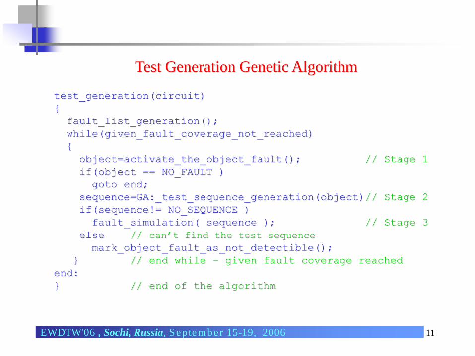
Test Generation Genetic Algorithm
test_generation(circuit)
{
fault_list_generation();
while(given_fault_coverage_not_reached)
{
object=activate_the_object_fault(); // Stage 1
if(object == NO_FAULT )
goto end;
sequence=GA:_test_sequence_generation(object)// Stage 2
if(sequence!= NO_SEQUENCE )
fault_simulation( sequence ); // Stage 3
else // can’t find the test sequence
mark_object_fault_as_not_detectible();
} // end while – given fault coverage reached
end:
} // end of the algorithm
EWDTW'06 , Sochi, Russia, September 15-19, 2006
12
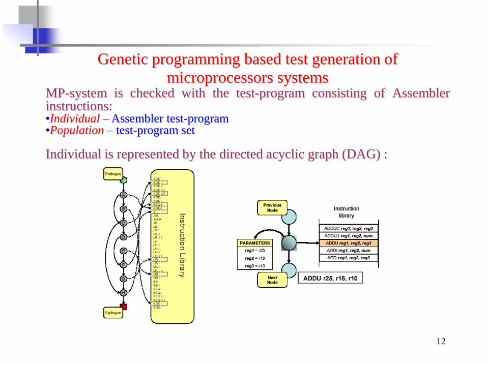
Genetic programming based test generation of
microprocessors systemsMP-system is checked with the test-program consisting of Assemblerinstructions:•Individual –Assembler test-program•Population – test-program set
Individual is represented by the directed acyclic graph (DAG) :

13
Genetic programming based test generation of
microprocessors systems
❖ Evolutionary ( + ) strategy, where
- population power, - offspring number.
❖ Tournament selection is applied.
❖ Genetic operators:mutation – a new node is inserted into the DAG in a random position;
– an existing internal node is removed from DAG;
– modifying parameters of an existing internal node;
crossover – 2 different test-programs produce the 2 offspring by classical 1-
point crossover. At first, parents are analyzed to detect potential cutting
points, i.e., DAG nodes which create disjoint sub-graphs when are removed.

14
There are also the following special nodes in the program:
➢Start node
➢Stop node
➢Subprogram calling nodes
➢Library subprogram calling nodes
There are also parameters tuning, for example, the minimum and the maximum
time for a program to run.
The instruction library describes the assembly syntax, listing each possible
instructions with the syntactically correct operands.
Test programs are implemented by modifying directed graph topology and by
crossover and mutation parameters inside directed graph nodes.
A population of individuals is cultivated, each individual representing a test
program. In each step , an offspring of new individuals are generated. Parents
are selected using tournament selection with tournament size (i.e., individuals
are randomly selected and the best is picked ). Each new individual is generated
by applying three mutation and crossover operators are implemented and applied
with own probabilities respectively.
15
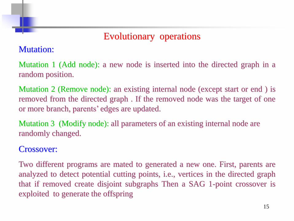
Mutation:
Mutation 1 (Add node): a new node is inserted into the directed graph in a
random position.
Mutation 2 (Remove node): an existing internal node (except start or end ) is
removed from the directed graph . If the removed node was the target of one
or more branch, parents’ edges are updated.
Mutation 3 (Modify node): all parameters of an existing internal node are
randomly changed.
Crossover:
Two different programs are mated to generated a new one. First, parents are
analyzed to detect potential cutting points, i.e., vertices in the directed graph
that if removed create disjoint subgraphs Then a SAG 1-point crossover is
exploited to generate the offspring
Evolutionary operations

16
1
1 1
1
1
1
1
1
1
2
2
2
2
22
2
Crossover Point
Selected Sub-graph
Parent 1 Parent 2
1
1
1
1
1
1
Crossover Point
2
2
2
22
1
Offspring 2
Crossover
Point
2
22
1
12
2
2
22
Offspring 1
Crossover
Point
Selected Sub-graph
17
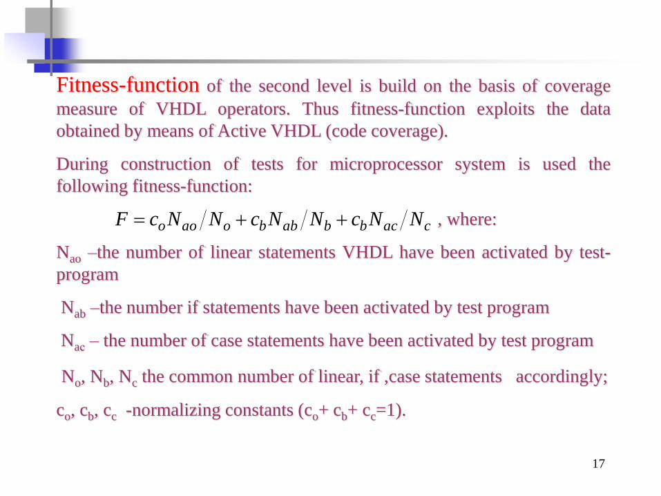
Fitness-function of the second level is build on the basis of coverage
measure of VHDL operators. Thus fitness-function exploits the data
obtained by means of Active VHDL (code coverage).
During construction of tests for microprocessor system is used the
following fitness-function:
, where:
Nao –the number of linear statements VHDL have been activated by test-
program
Nab –the number if statements have been activated by test program
Naс – the number of case statements have been activated by test program
No, Nb, Nc the common number of linear, if ,case statements accordingly;
co, cb, cc -normalizing constants (co+ cb+ cc=1).
cacbbabboaoo NNcNNcNNcF

18
generation of test-program initial population;
While (not attained maximum number of generation)
{
// loop according to generations
Generation of various paths for each test program;
While (not attained stop condition )
//loop according to paths
{
Test-program generation according to correspondent path
Compilation of test-program to binary code
Entry to Active VHDL environment
Loading of binary code to ROM of microprocessor
system VHDL model
Estimation of test program coverage using Active VHDL
Exit from Active VHDL environment;
Calculation of fitness-function according to correspondent path;
} // end of loop according to paths
Calculation of fitness function for test-program
(graph);
//creation of the next generation;
Selection of parents according to fitness-function value;
Crossover;
Mutation;
Reduction of population;
} //end of loop according to generations
The algorithm of test program generation
19
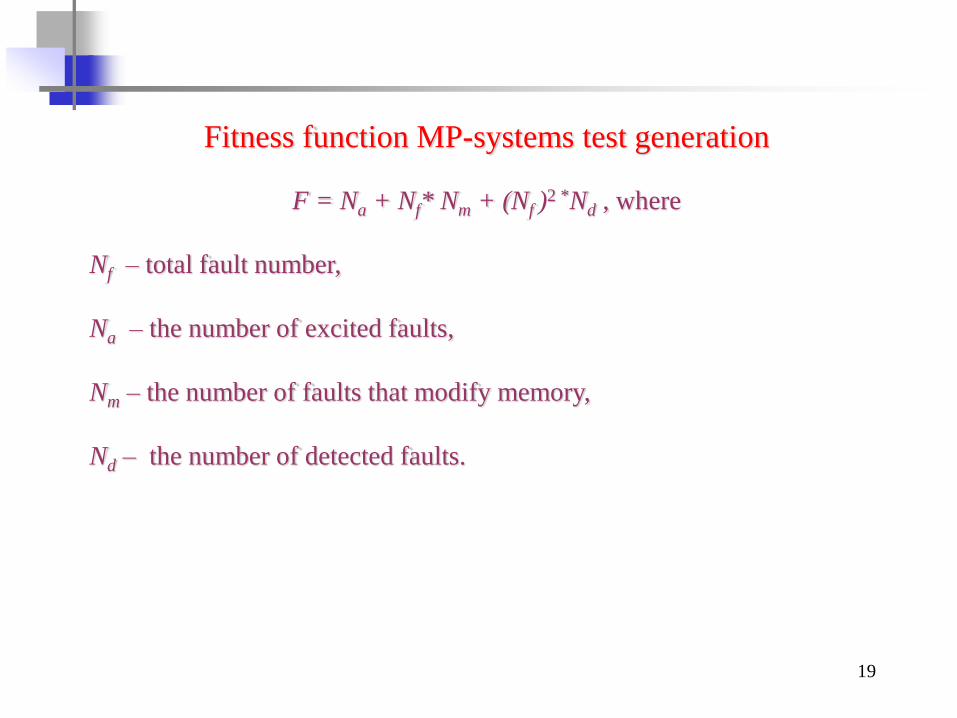
Fitness function MP-systems test generation
F = Na + Nf* Nm + (Nf )2 *Nd , where
Nf – total fault number,
Na – the number of excited faults,
Nm – the number of faults that modify memory,
Nd – the number of detected faults.
20
Conclusion
Evolutionary calculations could be effectively applied to test generation
at all DS representation levels:
1. Structural (gate) level:
❖ combinational logical circuits;
❖ sequential logical circuits;
2. FSM and structural levels:
❖ highly sequential circuits ;
3. Microprocessor systems.

21
Thanks for your attention!
You can write to the authors by e-mails:
•Yuriy A. Skobtsov: [email protected]
•Vadim Yu. Skobtsov: [email protected]
Top Related